

Page 1
Manual
EN 3.05 Version 2105
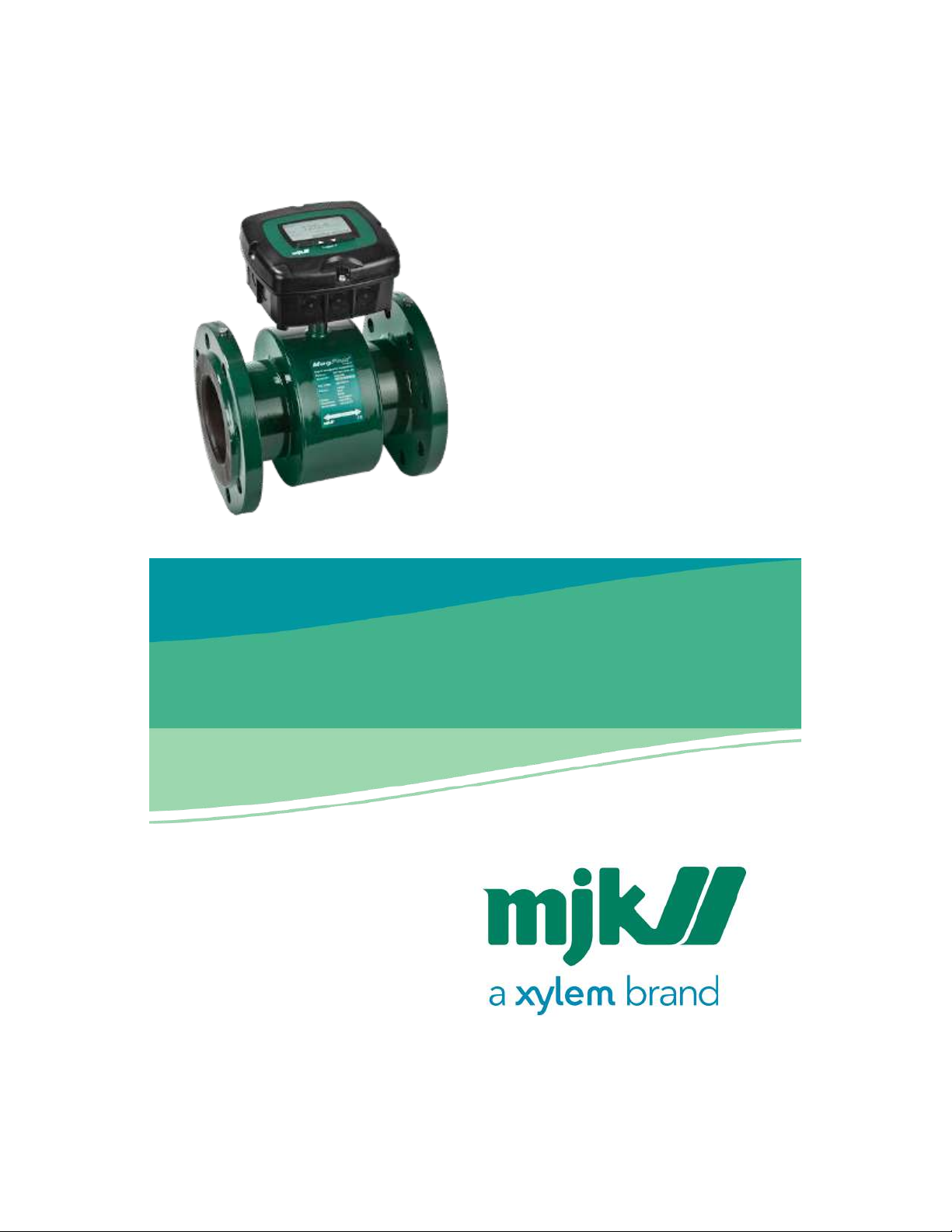
MagFlux® Series
ELECTROMAGNETIC FLOWMETER
Find Quality Products Online at: [email protected]
www.GlobalTestSupply.com
Page 2

MagFlux® Series
EN 3.05 Version 2105
2
Your notes:
Find Quality Products Online at: [email protected]
www.GlobalTestSupply.com
Page 3

MagFlux® Series
EN 3.05 Version 2105
3
Table of Contents
MJK declaration of conformity.................................................................................................. 8
Introduction.................................................................................................................................9
Introduction - MagFlux® Q ....................................................................................................9
Operating principles ..............................................................................................................9
The MagFlux® Flow Meter.................................................................................................. 10
Safety, repair and product identification...............................................................................11
Safety instructions................................................................................................................ 11
Physical mounting................................................................................................................ 12
Repair .................................................................................................................................... 12
MJK product identification ................................................................................................. 12
Flow sensor................................................................................................................................14
Minimum conductivity......................................................................................................... 14
Liner selection ...................................................................................................................... 14
Liner selection, cont. ........................................................................................................... 14
Electrode selection.............................................................................................................. 14
Mounting location ............................................................................................................... 14
Pressure loss......................................................................................................................... 16
Accuracy ............................................................................................................................... 17
MJK sizing............................................................................................................................. 17
Sizing chart ........................................................................................................................... 20
Pipe system........................................................................................................................... 23
Pipe system - MagFlux Q special conditions................................................................ 27
Cabinet mounted on the flow sensor................................................................................ 28
Potential equalization and grounding .............................................................................. 28
Type 7100/7200/8200 in conductive pipes ................................................................. 28
MagFlux® in conductive pipes, MagFlux® Q ...........................................................29
Type 7100/7200/8200 in non-conductive pipes......................................................... 29
MagFlux® in non-conductive pipes, MagFlux® Q ...................................................29
Cathodic protection ............................................................................................................ 30
Type 7100/7200 in conductive pipes ...........................................................................30
Type 7100/7200 in non-conductive pipes ...................................................................30
Flow converter ..........................................................................................................................31
Electrical mounting.............................................................................................................. 31
Power supply........................................................................................................................ 32
Change power supply voltage 230/115 V AC ................................................................. 33
Analogue output.................................................................................................................. 36
Digital outputs...................................................................................................................... 36
Digital input.......................................................................................................................... 37
Local (compact) flow sensor............................................................................................... 38
Remote flow sensor ............................................................................................................. 38
Converter connection board - local .................................................................................. 40
MJK Connection board - remotely mounted converter ................................................. 41
System configuration examples..............................................................................................42
Find Quality Products Online at: [email protected]
www.GlobalTestSupply.com
Page 4

MagFlux® Series
EN 3.05 Version 2105
4
MJK compact converter and display unit on flow sensor............................................... 42
MJK remote converter with connection box on flow sensor ......................................... 42
Wiring schematic #1............................................................................................................ 43
MJK remote display and multiple converters wiring ...................................................... 44
Wiring schematic #2............................................................................................................ 45
Startup........................................................................................................................................47
MJK initial checks................................................................................................................. 47
Initial flow measurement..................................................................................................... 47
Flow direction check ........................................................................................................... 47
Language selection ............................................................................................................. 47
MJK display read-out, one connected unit ...................................................................... 48
Display read-out, several connected units ....................................................................... 48
MJK display keys.................................................................................................................. 49
Initial setup ........................................................................................................................... 50
MagFlux® menus ......................................................................................................................53
Main menu............................................................................................................................ 53
Specify main screen............................................................................................................. 54
MJK factory settings ............................................................................................................ 55
Data logger........................................................................................................................... 60
Graph display................................................................................................................... 61
Password............................................................................................................................... 62
Set sensor name................................................................................................................... 64
Converter setup ................................................................................................................... 65
Minimum flow................................................................................................................... 67
Averaging .........................................................................................................................69
Units................................................................................................................................... 70
mA output......................................................................................................................... 70
Flow forward.................................................................................................................71
Flow reverse .................................................................................................................72
Forward & rev. (12mA=0) ...........................................................................................73
Forward & rev. (4mA=0) .............................................................................................74
Not in use......................................................................................................................75
MJK totalizers ................................................................................................................... 75
Settings and limits for resettable totalizers ..............................................................76
Resettable totalizers ....................................................................................................79
MJK batch counters 1 & 2............................................................................................... 82
Settings and limits for batch counters.......................................................................87
High flow/low flow........................................................................................................... 90
Flow direction................................................................................................................... 92
Empty pipe .......................................................................................................................94
24h flow............................................................................................................................. 95
Status................................................................................................................................. 95
Service menu.................................................................................................................... 97
Sersor calibration code...............................................................................................97
Converter software ver................................................................................................98
Product info ..................................................................................................................99
Find Quality Products Online at: [email protected]
www.GlobalTestSupply.com
Page 5

MagFlux® Series
EN 3.05 Version 2105
5
Reset counter time.......................................................................................................99
Internal meas. & cal. ................................................................................................. 100
Minimum velocity...................................................................................................... 100
Calibrate mA ............................................................................................................. 101
Test velocity............................................................................................................... 103
Freeze coil ................................................................................................................. 104
Read eventlog ........................................................................................................... 105
Back on stock ............................................................................................................ 105
Popup on/off ............................................................................................................. 106
Zero point calibration............................................................................................... 106
Verification................................................................................................................. 108
Display setup...................................................................................................................... 108
MJK communication modules documentation..........................................................109
Language........................................................................................................................109
Set clock..........................................................................................................................111
Modbus...........................................................................................................................111
Add Device................................................................................................................ 112
Change Device Address.......................................................................................... 113
Remove Device ......................................................................................................... 114
Change Display ID No.............................................................................................. 115
Set No. of Retries ...................................................................................................... 115
Change Modbus speed ........................................................................................... 116
Factory setting setup.....................................................................................................116
Display SW version ........................................................................................................117
Mechanical dimensions ........................................................................................................ 118
MJK standard flanges - EN-1092-1_2001 - Europe....................................................... 118
MagFlux Q sensor sizes and torque............................................................................120
MJK standard flanges - ANSI B 16.5 - U.S.A................................................................... 121
MJK standard flanges - AS-4087-2004 - Australia......................................................... 125
MJK standard flanges - AS-4087-2004 (continued #1)................................................. 127
MJK standard flanges - AS-4087-2004 (continued #2)................................................. 129
Appendix A. Pop-up and error messages.......................................................................... 132
Appendix B. MJK Field Link™ software.............................................................................. 136
System Requirements MJK Field Link™ .........................................................................136
Download MJK Field Link™ and connect a PC to the MagFlux® flow meter ............ 136
Save log data...................................................................................................................... 138
Upgrade display firmware. ............................................................................................... 138
Upgrade converter firmware............................................................................................ 139
Install/Add languages ....................................................................................................... 140
Appendix C. FAQs................................................................................................................. 142
Appendix D. Front panel cut-out drawing ......................................................................... 144
MJK cut-out download...................................................................................................... 145
Appendix E. MJK test certificate.......................................................................................... 146
Appendix F. Log files ............................................................................................................ 147
Appendix G. Digital input/output connections ................................................................. 151
Appendix H. Remote slave display unit .............................................................................. 152
Find Quality Products Online at: [email protected]
www.GlobalTestSupply.com
Page 6

MagFlux® Series
EN 3.05 Version 2105
6
Connection board for remote slave display unit ........................................................... 153
Converter connection board with master display unit ................................................. 154
Wiring..................................................................................................................................155
Configuration for the master unit ....................................................................................155
Configuration for the slave unit .......................................................................................155
Main menu overview ............................................................................................................. 156
Converter setup menu overview ......................................................................................... 158
Service menu overview ......................................................................................................... 164
Display setup menu overview .............................................................................................. 168
Find Quality Products Online at: [email protected]
www.GlobalTestSupply.com
Page 7

MagFlux® Series
EN 3.05 Version 2105
7
Contact
You can always contact your local representative or the MJK hotline for advice
and guidance:
other products and the people behind them.
Find Quality Products Online at: [email protected]
www.GlobalTestSupply.com
Page 8
MagFlux® Series
EN 3.05 Version 2105
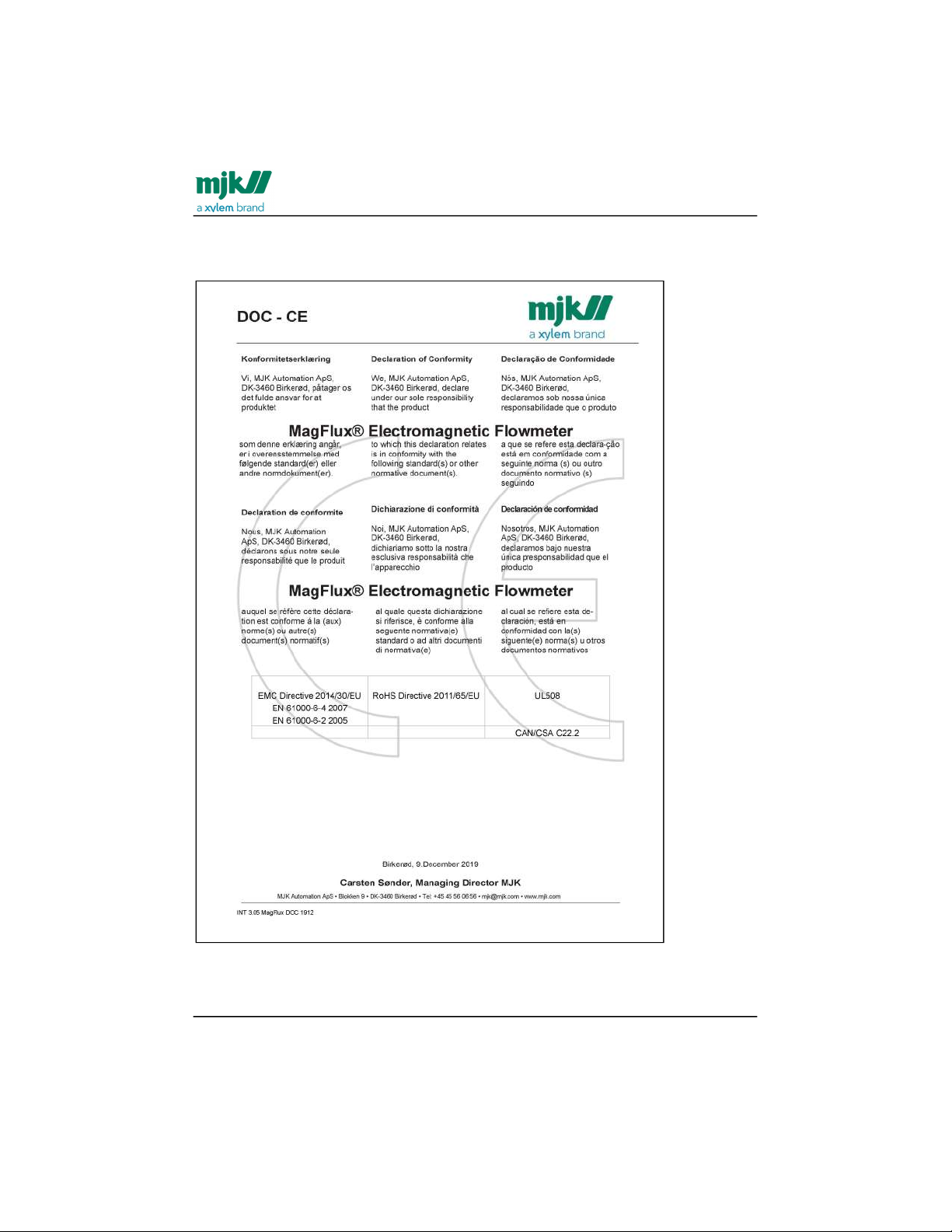
MJK declaration of conformity /
8
MJK declaration of conformity
Find Quality Products Online at: [email protected]
www.GlobalTestSupply.com
Page 9
MagFlux® Series
EN 3.05 Version 2105
Introduction /Introduction - MagFlux® Q
9
1.
Introduction
The MagFlux® is suitable for flow measurement in all kinds of conductive fluids, and it is
especially suited for flow measurement of water, waste water, sludge and other fluids
containing particles.
The flow meter is easy to install and put into service. However, read this manual first to
learn about the MagFlux® electromagnetic flow meter and all its features.
Introduction - MagFlux® Q
MagFlux® Q is especially suited for seawater and similar conditions as it is created in
ABS plast, no outer parts in metal.
Operating principles
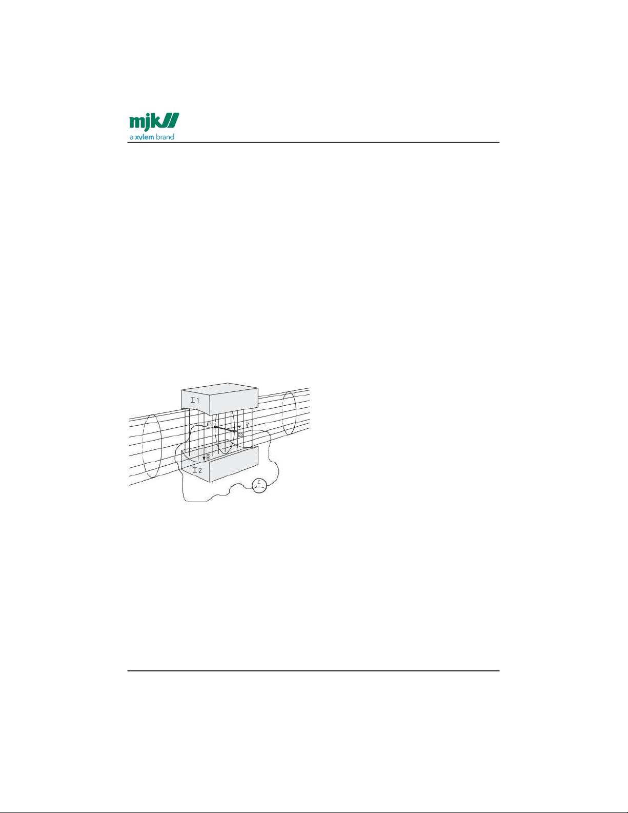
The MagFlux® electromagnetic flow meter is an instrument for measuring the flow of
conductive fluid using Faraday's electromagnetic induction law, and consequently the
fluid must be electrically conductive.
As illustrated above, a magnetic field with density B - perpendicular to the direction of
flow - stretches across a fluid flowing within an electrically isolated pipe.
The magnetic flux will induce a voltage difference (E) that can be measured between
two electrodes arranged perpendicular to the direction of flow and the magnetic field.
The voltage is proportional to the velocity (V) of the fluid.
E = B x D x V x k [Volt] where
E is the voltage that is induced between the two electrodes
B is the magnetic flux density
D is the distance between the two electrodes
V is the fluid velocity
k is a dimensionless constant
The flow of the fluid Q (m3/s) is given by the following formula:
Find Quality Products Online at: [email protected]
www.GlobalTestSupply.com
Page 10

MagFlux® Series
EN 3.05 Version 2105
Introduction /The MagFlux® Flow Meter
10
2. Q = π x D2 x V / 4 => V = 4 / (π x D2) where
π : is the constant pi (= 22/7)
D: is the internal diameter
V: is the fluid velocity
The combination of above formulas 1. and 2. gives the following formula:
E = K x B x D x Q x 4 / (π x D x D) = 4 K x B x Q / (π x D)
Evidently, the voltage E is proportional to the actual flow.
The MagFlux® Flow Meter
Measurement
Electromagnetic flow meters may have either direct current (DC) or alternating current
(AC) excitation. When systems are AC excited, electrostatic and/or electromagnetic
noise may influence the measurements. A DC excited system however, is less sensitive
to noise produced by electromagnetic induction, simply because the voltage induced
over the electrodes will be a DC voltage. The drawbacks are measurement errors due to
electrochemical polarization between the electrodes and the fluid.
The MagFlux® flow meters are excited by a 2.5 Hz square wave and thereby eliminate
the drawbacks of both DC and AC systems.
A microprocessor receives and measures the amplitude of the pulse with a 16-bit
resolution, and converts and displays the result on the display unit.
Electrode cleaning
Electrode cleaning is always activated to maintain clean and accurate electrodes. The
operating principle is a 55 Hz AC voltage superimposed on the normal 2.5 Hz square
wave. This step effectively reduces the risk of a dirt layer build-up on the electrodes that
eventually will deteriorate and finally isolate electrical contact to the flow media.
Find Quality Products Online at: [email protected]
www.GlobalTestSupply.com
Page 11
MagFlux® Series
EN 3.05 Version 2105
Safety, repair and product identification /Safety instructions
11
1.
2.
3.
4.
Safety, repair and product identification
Safety instructions
Read this manual carefully.
Pay attention to the environment on the installation site.
Wear necessary protective equipment and follow all current safety regulations.
The MagFlux® can invoke a start signal for dangerous machinery. Always ensure
that connected machinery and other equipment are effectively put out of service
(that is to remove the main fuses and lock main and security switches in offposition) before commencing configuration, fault finding, servicing, maintenance
work, etc.
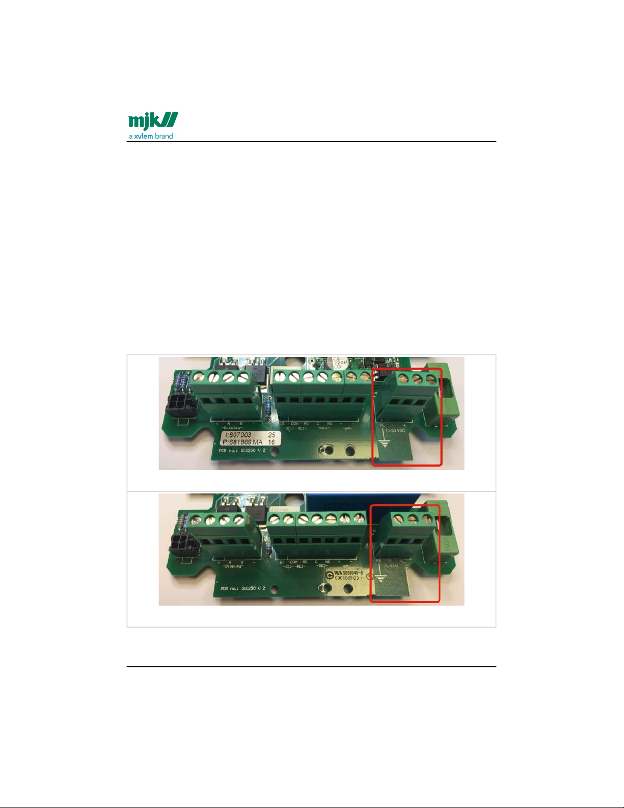
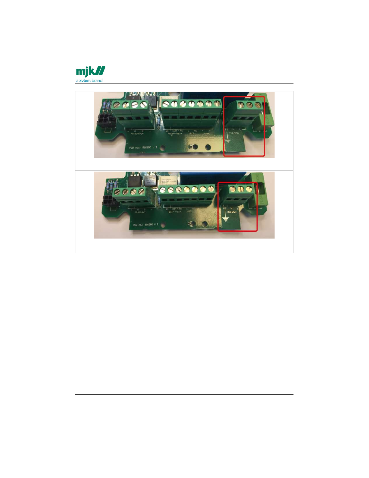
Warning: There is a risk of lethal, electrical shock from Mains supply terminals named
N and L or - and +. Be careful not to touch these terminals - marked in red in the
following - while the MagFlux® is being serviced.
10-30 VDC
24 VAC
Find Quality Products Online at: [email protected]
www.GlobalTestSupply.com
Page 12
MagFlux® Series
EN 3.05 Version 2105
Safety, repair and product identification /Physical mounting
12
115 VAC
230 VAC
Physical mounting
The MagFlux® flow converter/flow meter must not be mounted in explosion hazardous
areas!
Repair
Repair must only be made by this company or by a service representative approved by
us.
MJK product identification
A delivery will usually consist of a MagFlux® converter and a MagFlux® flow sensor.
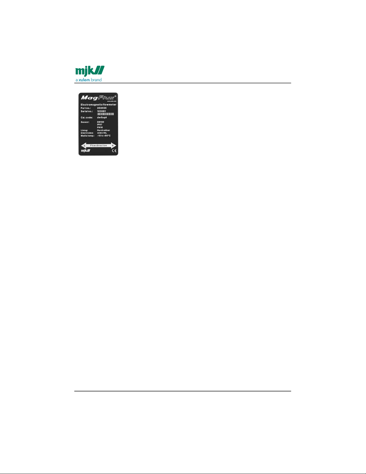
Check that the item(s) delivered corresponds to the ordered item(s). The part number,
serial number, calibration code and electrode/lining data are printed on an
identification label on the flow sensor (see the following example):
Find Quality Products Online at: [email protected]
www.GlobalTestSupply.com
Page 13
MagFlux® Series
EN 3.05 Version 2105
Safety, repair and product identification /MJK product identification
13
This calibration code (Cal. code) is unique and provides the
MagFlux® converter with information about flow sensor number,
nominal diameter of the flow sensor and calibration data for the
flow sensor.
The current converter firmware requires an eight character input,
but also accepts six characters plus two OK. The current example
(dw5uq4) would require that you enter: d w 5 u q 4 OK OK, where
OK indicates that you press the OK key without selecting any
character. Only lower case letters can be entered via the MagFlux®
keypad.
If changes are needed to the unique sensor calibration code
following initial setup, this is the calibration code that the Sensor Calibration Code
menu must contain (see Initial setup(see page50)).
Find Quality Products Online at: [email protected]
www.GlobalTestSupply.com
Page 14

MagFlux® Series
EN 3.05 Version 2105
Flow sensor /Minimum conductivity
14
•
•
•
•
•
•
•
•
•
•
•
•
•
•
Flow sensor
The following conditions must be obtained to get the full benefit of the MagFlux® flow
sensor.
Minimum conductivity
The conductivity of the measured media must be greater than 5 µS/cm.
Liner selection
Use hard rubber lining for drinking water and waste water.
Liner selection, cont.
Use PTFE lining for chemicals and food industries
Use ABS lining for seawater (applies to MagFlux® Q only).
Electrode selection
Steel AISI 316TI-1.4571 for general purpose, sewage, water and district
heating systems
Hastelloy for sea water.
Tantalum, titanium and platinum for chlorine and other aggressive chemicals.
Mounting location
To obtain a stable and accurate flow measurement it is very important that the flow
sensor is mounted correctly in the pipe system.
There must be no flow fluctuations.
Avoid locations where vacuum can occur; especially for flow sensors with PTFE
linings.
Avoid locations with vibrations from, for example, pumps.
Avoid locations with extensive temperature changes.
Avoid corrosive environments and locations with a great risk of condensation, or
consult factory for special builds for these locations.
Avoid air at the measuring point.
Take care that condensate and water cannot enter the connector box on the flow
sensor.
There must be sufficient free space around the flow sensor.
Find Quality Products Online at: [email protected]
www.GlobalTestSupply.com
Page 15
MagFlux® Series
EN 3.05 Version 2105
Flow sensor /Mounting location
15
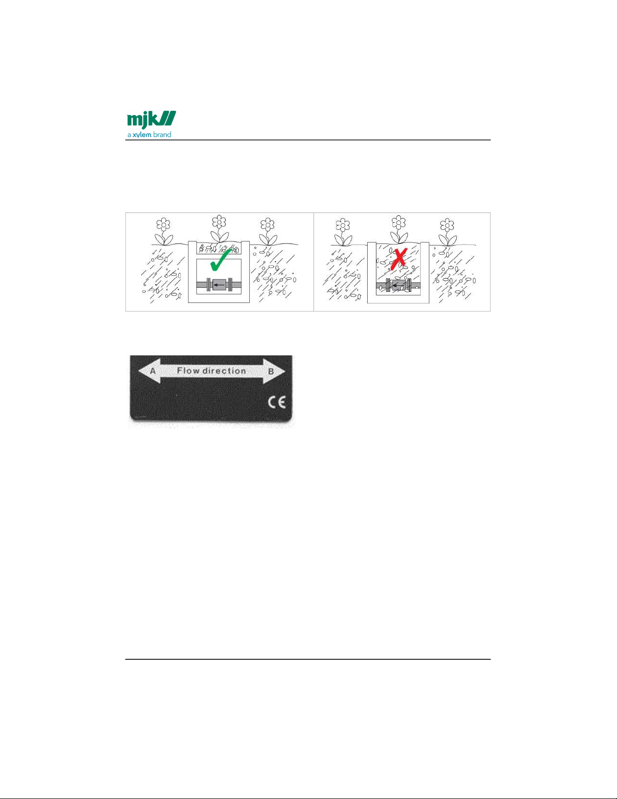
However, the MagFlux® can be buried in a well or closed dug-down space. It is created
with a significant layer of protective paint preventing rust. But gravel and dirt can wear
the paint, thereby decreasing the level of protection. Therefor, it is strongly
recommended to leave a gravel-free and dry space for the MagFlux® installation as
illustrated below.
Important: Observe that the correct flow direction is set in the MagFlux® Converter
Setup menu and in the Service Menu. Default flow direction is A (flow direction towards
left).
The flow directions A or B are clearly shown on the name plate.
Find Quality Products Online at: [email protected]
www.GlobalTestSupply.com
Page 16
MagFlux® Series
EN 3.05 Version 2105
Flow sensor /Pressure loss
16
Pressure loss
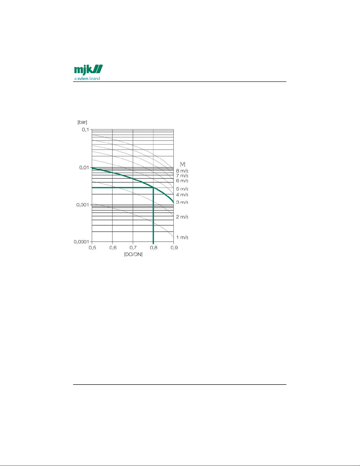
Pressure loss can easily be determined, if the nominal pipe diameter is greater than the
MagFlux® flow sensor. See this pressure loss diagram:
The diagram illustrates that decreasing the internal diameter from 100 mm (DN) to 80
mm (DO) will cause a pressure loss of 0.003 Bar @3 m/s.
Find Quality Products Online at: [email protected]
www.GlobalTestSupply.com
Page 17
MagFlux® Series
EN 3.05 Version 2105
Flow sensor /Accuracy
17
Accuracy
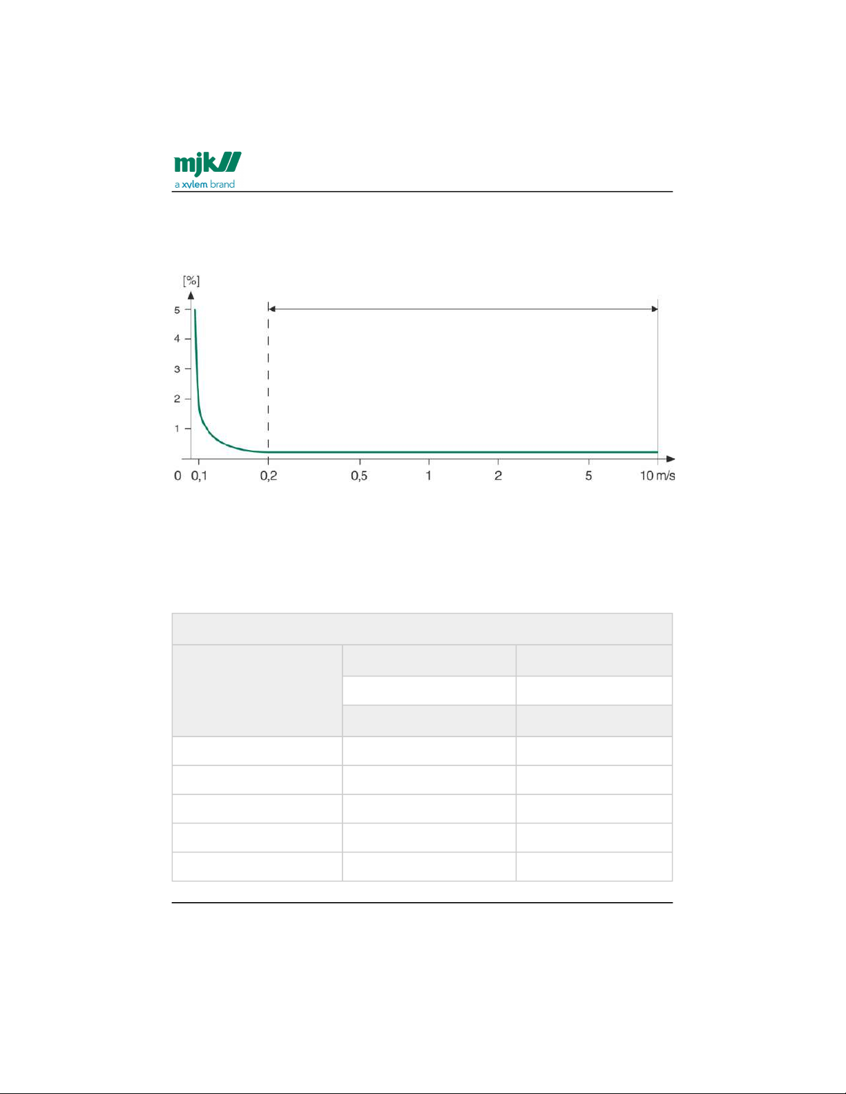
According to the type and size of the flow sensor, the measuring accuracy will be better
than 0.25%, provided that the flow sensor has the correct dimension.
MJK sizing
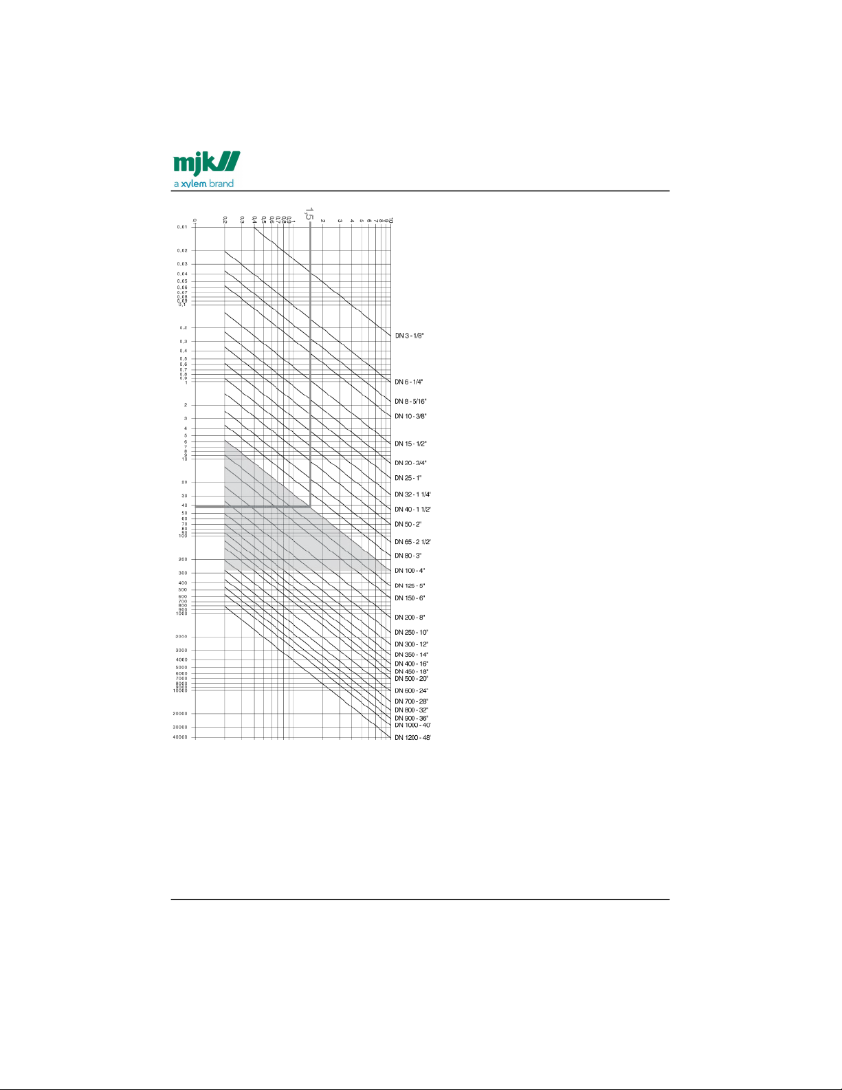
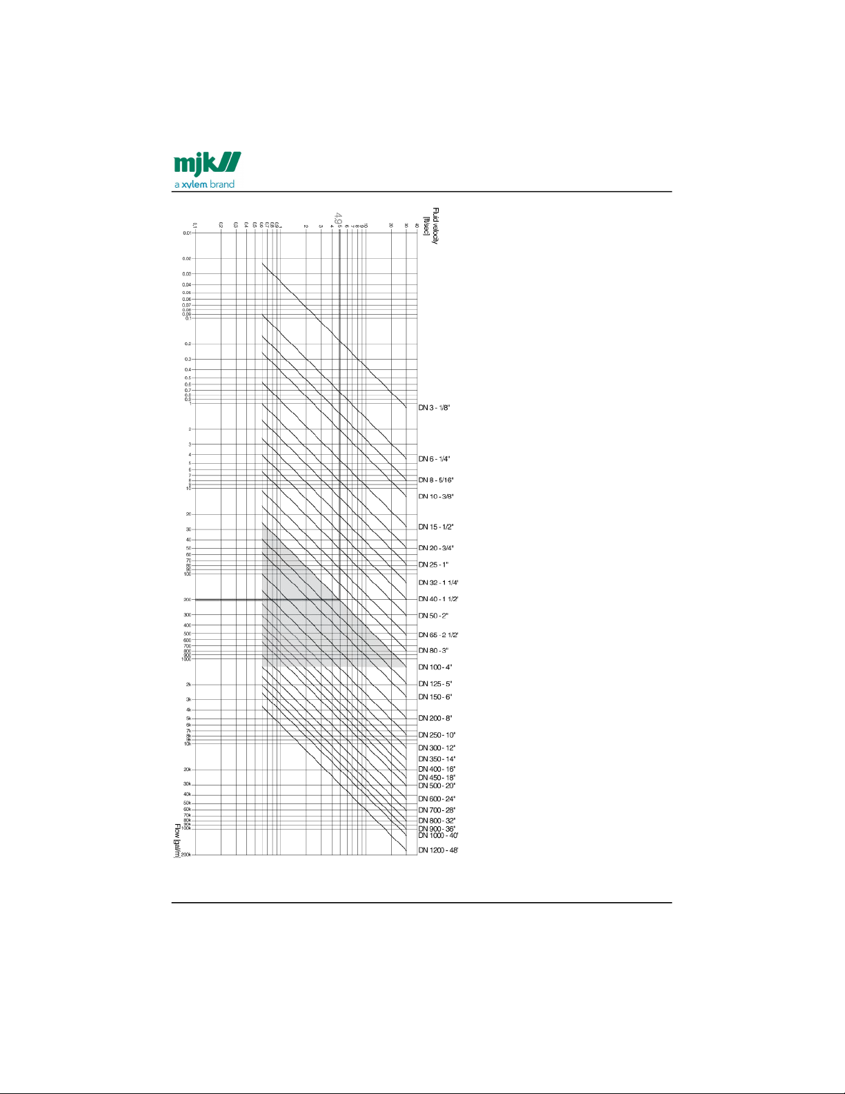
The flow sensor should be selected so the flow velocity through the sensor will be
between 0.2-10 m/s. We recommend that flow velocities in tubes are kept between 1-3
m/s for reliable and safe operation. See also the dimensioning table below and the
dimensioning chart in the following section.
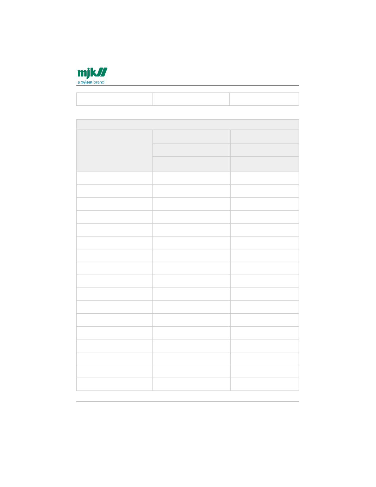
Min and max flow, metrics
DN Qmin Qmax
0.2 m/s 10 m/s
[l/h] [l/h]
15 127 6362
20 226 11304
25 353 17676
32 579 28944
40 905 45360
Find Quality Products Online at: [email protected]
www.GlobalTestSupply.com
Page 18
MagFlux® Series
EN 3.05 Version 2105
Flow sensor /MJK sizing
18
50 1414 70560
Min and max flow, metrics
DN Qmin Qmax
0.2 m/s 10 m/s
[m3/h] [m3/h]
65 2,39 119
80 3,62 181
100 5,65 283
125 8,84 442
150 12,7 636
200 22.6 1131
250 35.3 1767
300 50.9 2545
350 69.3 3464
400 90.5 4524
450 115 5726
500 141 7069
600 204 10179
700 277 13854
800 362 18095
900 458 22902
1000 565 28274
Find Quality Products Online at: [email protected]
www.GlobalTestSupply.com
Page 19
MagFlux® Series
EN 3.05 Version 2105
Flow sensor /MJK sizing
19
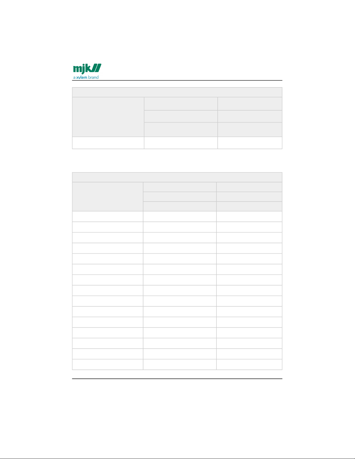
Min and max flow, metrics
DN Qmin Qmax
0.2 m/s 10 m/s
[m3/h] [m3/h]
1200 814 40715
The Q
max
is equal to 20 mA factory preset.
Min and max flow, imperial
Qmin Qmax
0.6 ft./s 30 ft./s
[GPM] [GPM]
½” 0.559 28.0
¾" 0.995 49.76
1” 1.550 77.82
1¼" 2.549 127.4
1½” 3.984 199.7
2” 6.226 310.7
2½” 10.52 523.9
3” 15.93 796.9
4” 24.87 1246
5” 38.92 1946
6” 55.91 2800
8" 99.50 4,979
10" 155.4 7,780
12" 224.1 11,205
14" 305.1 15,258
Find Quality Products Online at: [email protected]
www.GlobalTestSupply.com
Page 20
MagFlux® Series
EN 3.05 Version 2105
Flow sensor /Sizing chart
20
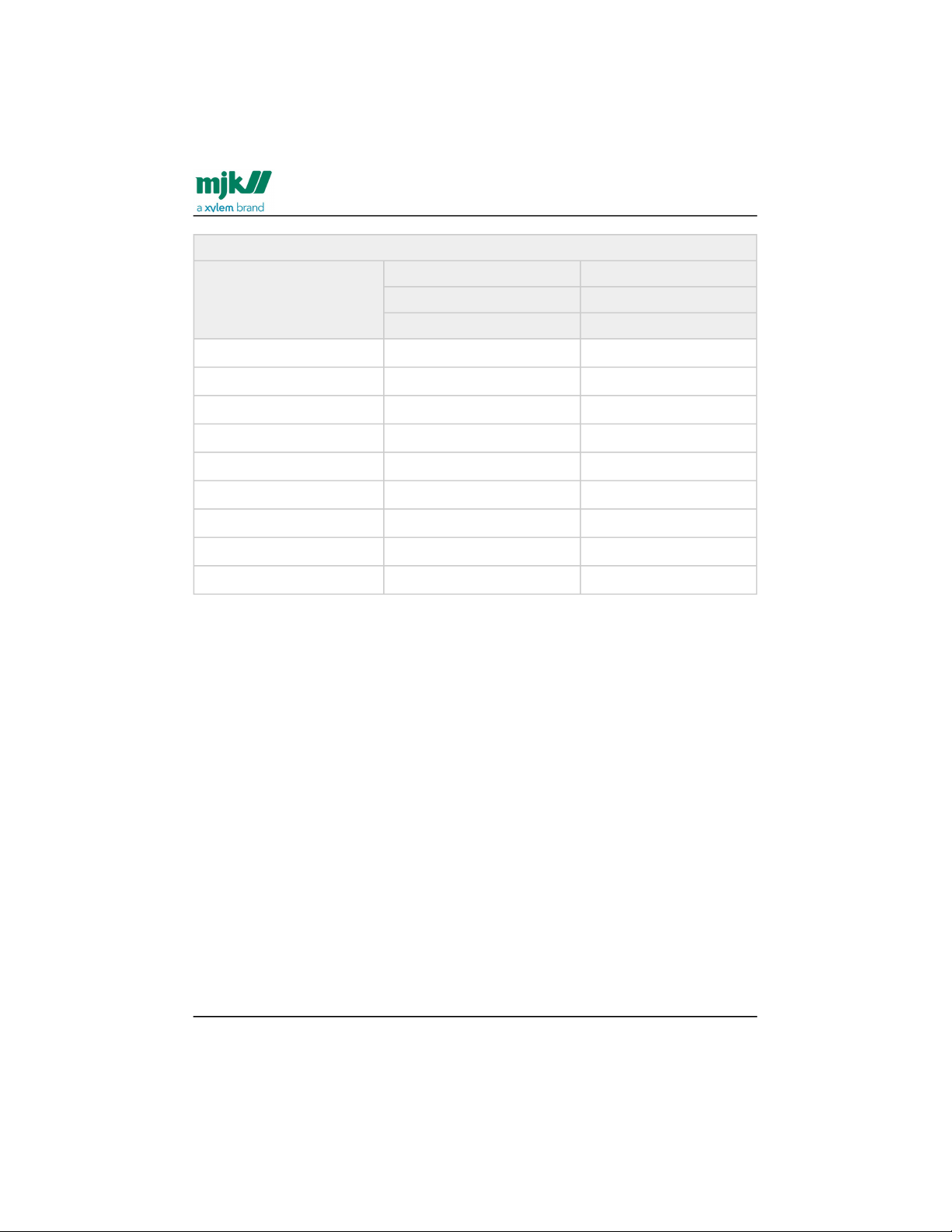
Min and max flow, imperial
Qmin Qmax
0.6 ft./s 30 ft./s
[GPM] [GPM]
16" 398.5 19,919
18” 506.3 25,210
20” 620.8 31,120
24” 999.1 44,910
28” 1220 74,920
32” 1594 79,620
36” 2017 100,800
40” 2497 124,500
48” 3584 179,300
Sizing chart
Example: A MagFlux® with an internal diameter of 100 mm can measure flow rates
between approx. 5.6 m3/h and 290 m3/hand the fluid velocity is 1.5 m/s at a flow rate of
approx. 42 m3/h.
Find Quality Products Online at: [email protected]
www.GlobalTestSupply.com
Page 21
MagFlux® Series
EN 3.05 Version 2105
Flow sensor /Sizing chart
21
Find Quality Products Online at: [email protected]
www.GlobalTestSupply.com
Page 22
MagFlux® Series
EN 3.05 Version 2105
Flow sensor /Sizing chart
22
Find Quality Products Online at: [email protected]
www.GlobalTestSupply.com
Page 23
MagFlux® Series
EN 3.05 Version 2105
Flow sensor /Pipe system
23
1.
Pipe system
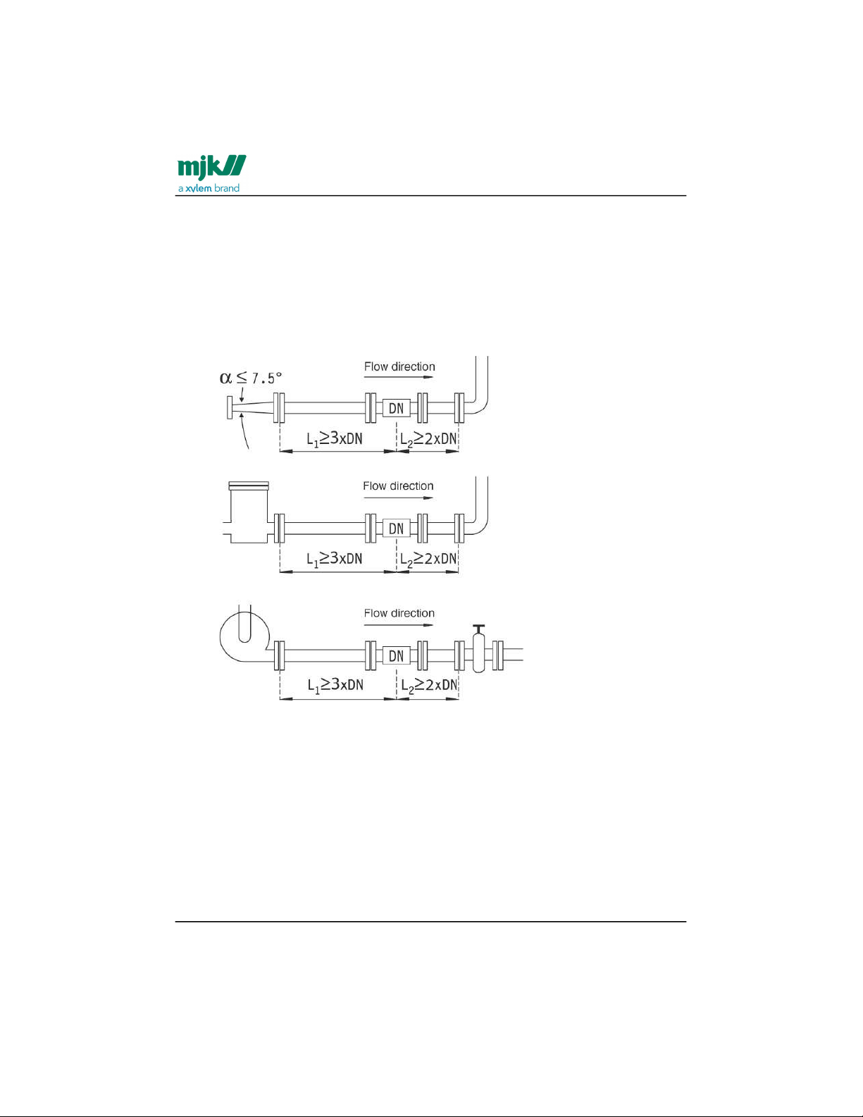
To ensure a laminar flow without turbulence upstream of the MagFlux® flow
sensor, the flow sensor must be mounted in a location which is free from
interfering elements like valves, Ts, bends, pumps, etc. For that reason, the
MagFlux® flow sensor must be mounted in a straight pipe at a distance from
interfering elements of minimum 3 x DN upstream and minimum 2 x DN
downstream.
Important: Valves should always be mounted on the downstream side of the
MagFlux® flow sensor!
Important:When installing a magnetic inductive flow meter, it is important to
comply with the installation criteria describedhere:
The mentioned respect distances for up/downstream flow respectively, are
minimum requirements.If your installation has an already turbulent flow profile
due to bends, valves, plug-in fittings etc. in the pipeinstallation, it may be
necessary with a longer respect distance than stated in the data sheet. For the
meter tocomply with its measuring accuracy, these respect distances apply both
before and after the meter. If in doubtabout the installation and the respective
respect distances, please contact support. We are happyto assist and advise on
Find Quality Products Online at: [email protected]
www.GlobalTestSupply.com
Page 24
MagFlux® Series
EN 3.05 Version 2105
Flow sensor /Pipe system
24
2.
3.
4.
the optimal location of the flow meter according to your application.
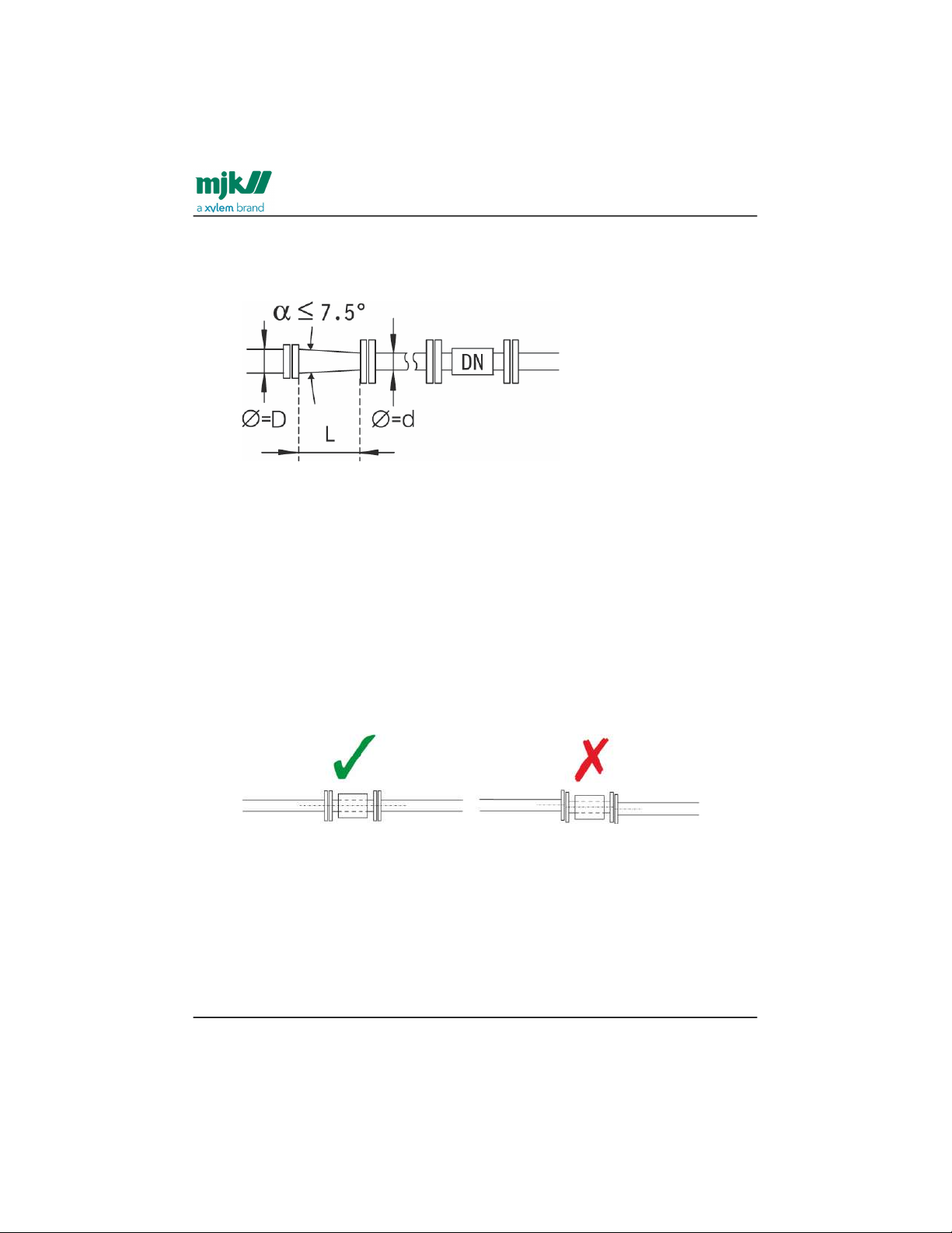
If it becomes necessary to use reducers, the inner angle must not exceed 7,5°.
The minimum length to keep the angle below 7,5° can be checked by means of
the formula below:
L = (D - d) x 7.63
where D is the large diameter and d the small diameter of the reducer.
Example: If a MagFlux® flow sensor in dimension DN 80 is mounted
downstream of a 100 mm pipe, the reducer must then have a length of minimum
152,6 mm in order to keep the inner angle below 7,5°.
Flange connections must be assembled concentrically on both the upstream and
the downstream side. Measuring accuracy will be affected by turbulence in the
liquid from poorly made connections.
Important: Gaskets and grounding rings must also be mounted concentrically!
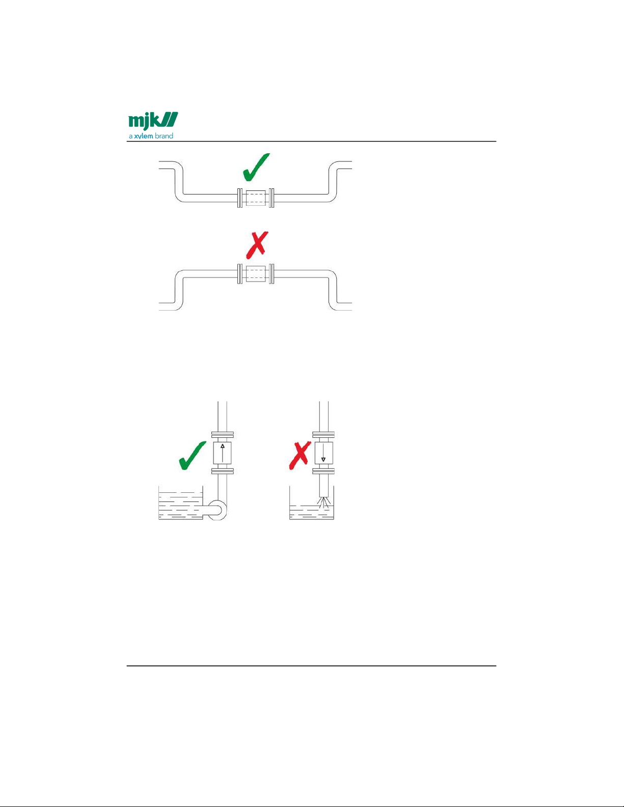
The MagFlux® flow sensor should always be filled with liquid. For that reason, the
flow sensor must not be mounted at the highest point of the pipe system or in
free outlets, where gravity could empty or partially empty the pipe.
Find Quality Products Online at: [email protected]
www.GlobalTestSupply.com
Page 25
MagFlux® Series
EN 3.05 Version 2105
Flow sensor /Pipe system
25
5.6.The MagFlux® flow sensor can be mounted vertically or horizontally. If the flow
sensor is mounted vertically, the flow direction should always be upwards. In that
way, the effect from possible bubbles in the liquid will be significantly reduced,
just as it will ensure that the flow sensor is always filled with liquid. In case the
liquid is carrying particles, for example when measuring sludge, sewage, etc., the
flow sensor must be mounted vertically.
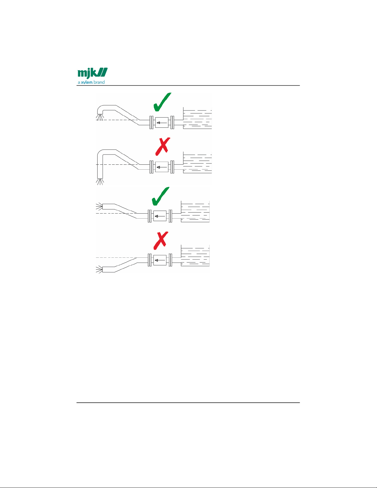
When mounting horizontally in pipes with free downstream outlet, the MagFlux®
flow sensor should be mounted such that it will always be filled with liquid, for
example in a bend situated lower than the height of the outlet. In case the liquid
is carrying particles, e.g. when measuring sludge, sewage etc. the flow sensor
must be mounted vertically.
Find Quality Products Online at: [email protected]
www.GlobalTestSupply.com
Page 26
MagFlux® Series
EN 3.05 Version 2105
Flow sensor /Pipe system
26
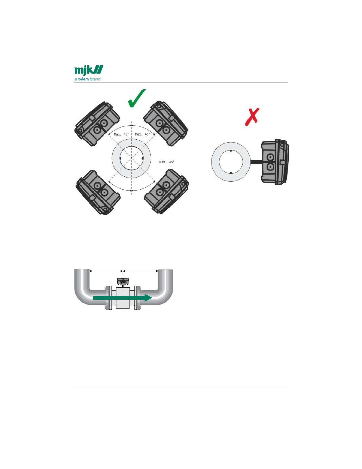
7. When mounting horizontally the MagFlux® flow sensor can be rotated max. +/45° seen from the connection end. If the flow sensor is rotated more than 45°,
one of the electrodes may not be in full contact with the liquid.
Find Quality Products Online at: [email protected]
www.GlobalTestSupply.com
Page 27
MagFlux® Series
EN 3.05 Version 2105
Flow sensor /Pipe system
27
Pipe system - MagFlux Q special conditions
For MagFlux® Q, a special design allows using a short build-in construction which
provides a very accurate flow measurement even at minimum one pipe diameter of
straight pipe upstream and one pipe diameter of straight pipe downstream from the
centre of the flow sensor.
At 1 x diameter before and after the sensor there will be an accuracy of up to 0,5%.
Find Quality Products Online at: [email protected]
www.GlobalTestSupply.com
Page 28
MagFlux® Series
EN 3.05 Version 2105
Flow sensor /Cabinet mounted on the flow sensor
28
Cabinet mounted on the flow sensor
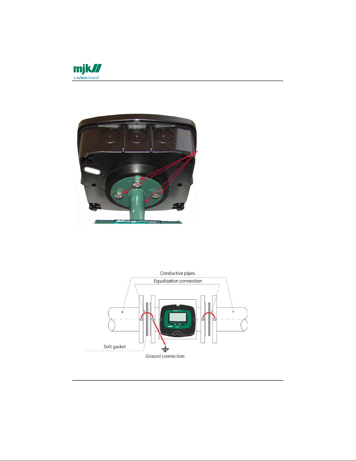
The cabinet is mounted on the flow sensor with four pcs. 6x12 hex cap screws.
Potential equalization and grounding
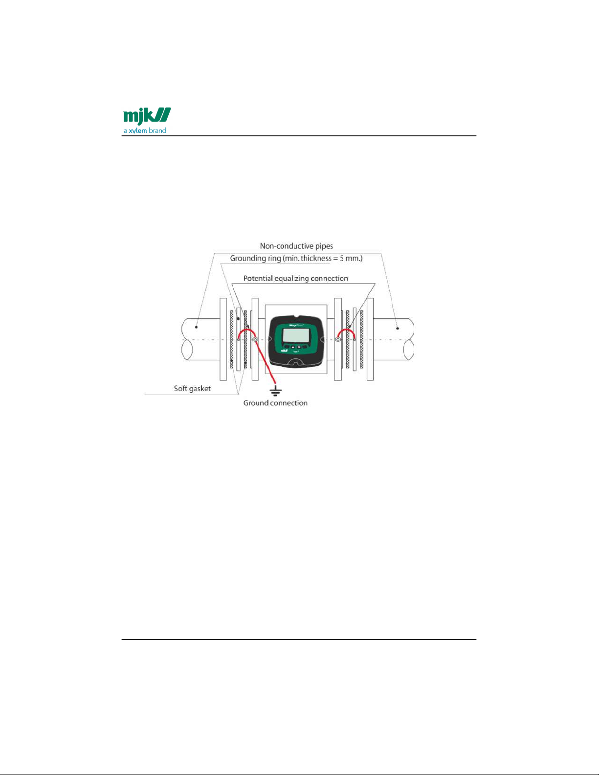
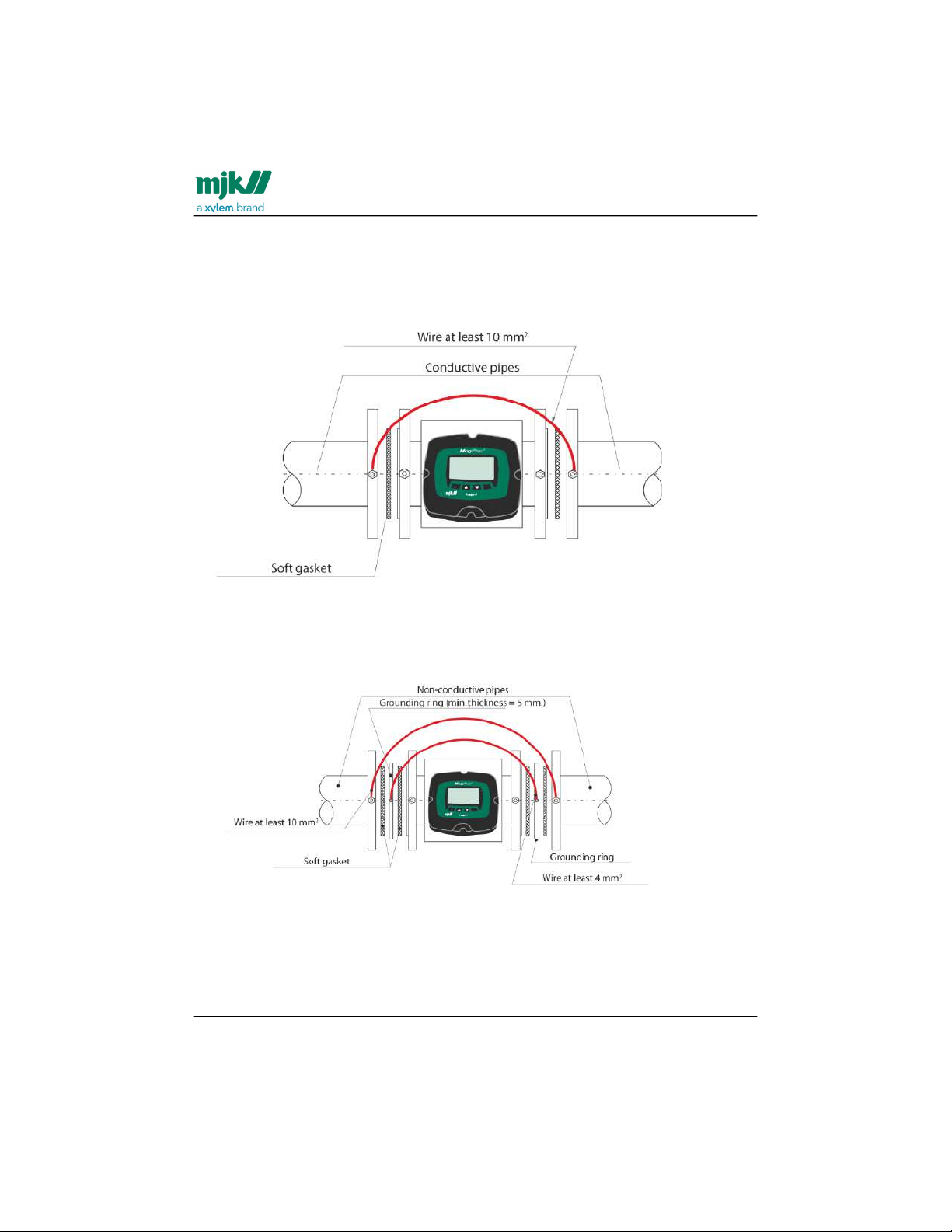
Type 7100/7200/8200 in conductive pipes
Note! The MagFlux® flow sensor must be connected to an effective ground connection,
and the wire dimension must be at least 1.5 mm2.
Find Quality Products Online at: [email protected]
www.GlobalTestSupply.com
Page 29
MagFlux® Series
EN 3.05 Version 2105
Flow sensor /Potential equalization and grounding
29
Note! Does not apply to the MagFlux® Q.
MagFlux® in conductive pipes, MagFlux® Q
Note! Does not apply to the MagFlux® Q.
Type 7100/7200/8200 in non-conductive pipes
Note! The MagFlux® flow sensor must be connected to an effective ground connection,
and the wire dimension must be at least 1.5 mm2.
Note! Does not apply to the MagFlux® Q.
MagFlux® in non-conductive pipes, MagFlux® Q
Note! Does not apply to the MagFlux® Q.
Find Quality Products Online at: [email protected]
www.GlobalTestSupply.com
Page 30
MagFlux® Series
EN 3.05 Version 2105
Flow sensor /Cathodic protection
30
Cathodic protection
Type 7100/7200 in conductive pipes
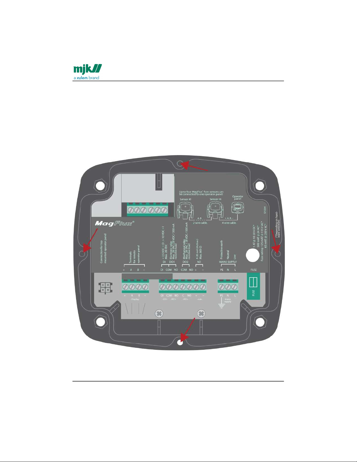
Note! The Sensor must be isolated from the cathodic protected pipes, this is done by
using insulated bolts and nylon washers.
Type 7100/7200 in non-conductive pipes
Note! The Sensor must be isolated from the cathodic protected pipes, this is done by
using insulated bolts and nylon washers.
Find Quality Products Online at: [email protected]
www.GlobalTestSupply.com
Page 31
MagFlux® Series
EN 3.05 Version 2105
Flow converter /Electrical mounting
31
Flow converter
Electrical mounting
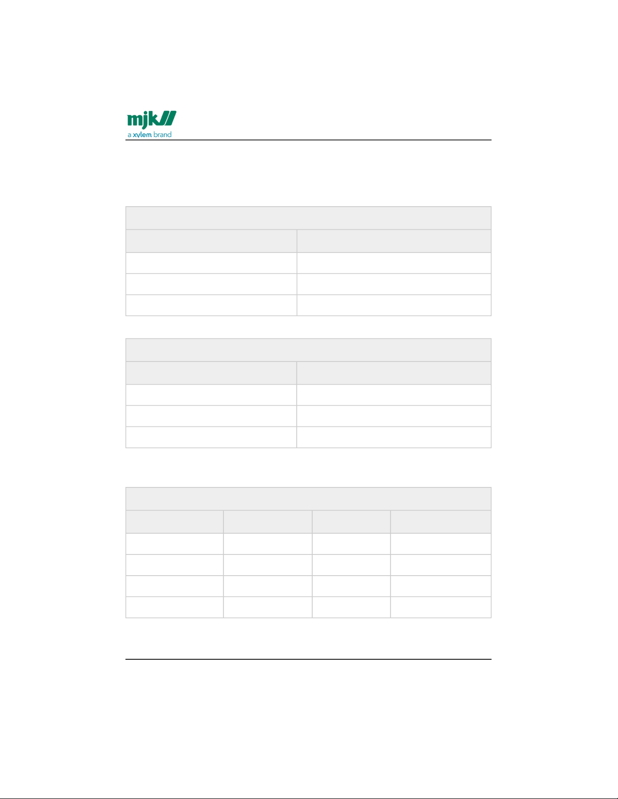
Warning: The MagFlux® flow converter/flow sensor must not be mounted in explosion
hazardous areas!
Loosen the four screws (position indicated by arrows) and remove the display unit to
gain access to the terminals.
Find Quality Products Online at: [email protected]
www.GlobalTestSupply.com
Page 32
MagFlux® Series
EN 3.05 Version 2105
Flow converter /Power supply
32
Power supply
The MagFlux® flow converter must be supplied from a properly fused mains outlet, a 24
volt AC outlet, or a 10 - 30 V DC power supply/battery.
Power Supply 230 V AC, 115 V AC or 24 V AC
Terminal Designation
PE Protective ground
N 230 / 115 / 24 V AC neutral
L 230 / 115 / 24 V AC live
Power Supply 10 - 30 V DC
Terminal Designation
PE Protective ground
- DC neutral
+ DC live
The internal fuse ratings are:
Internal Fuse Ratings
Voltage Rating Order no. Dimension
230 V AC 63 mA T 550030 5 x 20 mm
115 V AC 125 mA T 550035 5 x 20 mm
24 V AC 500 mAT 550049 5 x 20 mm
10 - 30 V DC 1.0AT 550051 5 x 20 mm
The technical specifications/requirements for a 10 - 30 V DC power supply/battery are:
Find Quality Products Online at: [email protected]
www.GlobalTestSupply.com
Page 33
MagFlux® Series
EN 3.05 Version 2105
Flow converter /Change power supply voltage 230/115 V AC
33
1.
2.
3.
4.
5.
Technical Specifications for 10 - 30 V DC Power Supply
Power consumption without display < 5 W
Power consumption with display < 8 W
Peak start current @12 V DC,1 second Approx. 1,5 A
Peak start current @24 V DC,1 second Approx. 1 A
Change power supply voltage 230/115 V AC
To change the input mains voltage from 230 VAC to 115 VAC (or vice verse) proceed as
follows:
Loosen the four screws on the front and lift out the display (see Electrical
mounting(see page31)).
Note down the color and position of the wires in the terminal blocks, and loosen
the terminal screws.
Unscrew the two screws that hold the metal cover and then remove it.
Unscrew the four screws that hold the mother PCB (the printed circuit board with
all the electrical components).
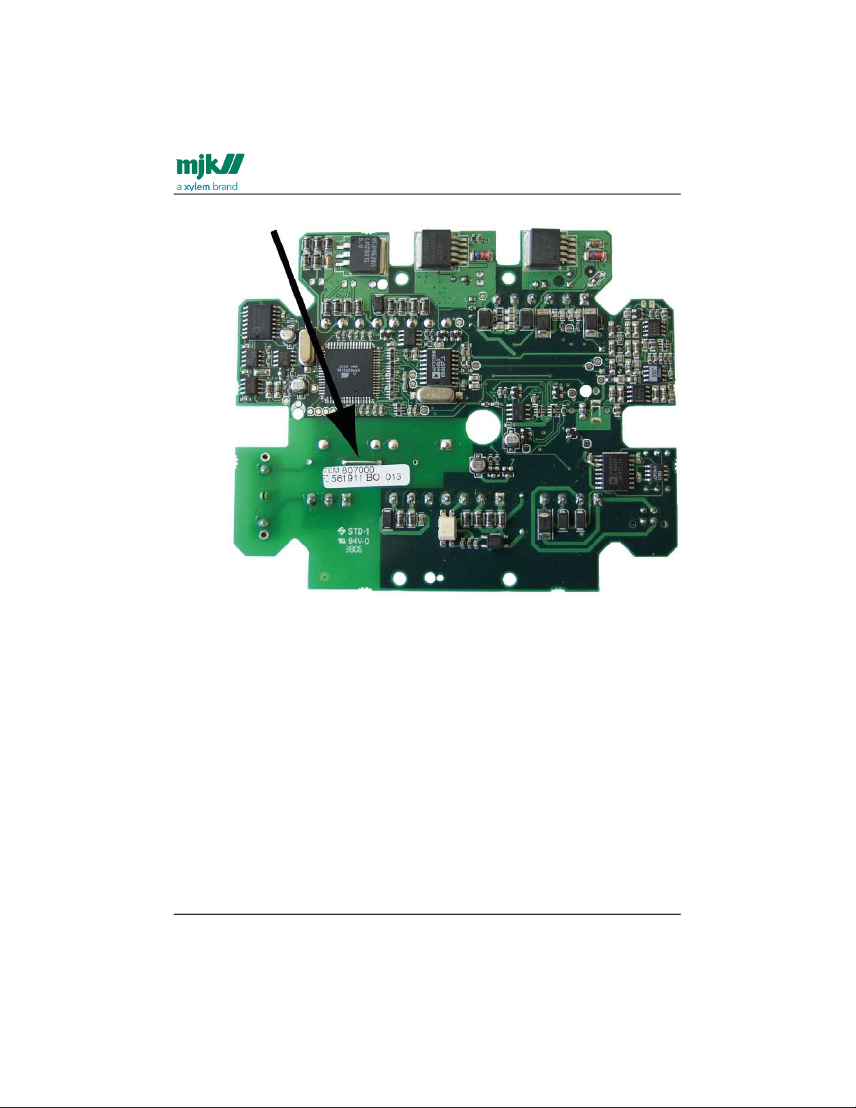
Remove the mother PCB and look at the back side. This is what you should see
(230 V AC configuration):
Find Quality Products Online at: [email protected]
www.GlobalTestSupply.com
Page 34
MagFlux® Series
EN 3.05 Version 2105
Flow converter /Change power supply voltage 230/115 V AC
34
6. Unsolder and remove the jumper indicated by the arrow.
Find Quality Products Online at: [email protected]
www.GlobalTestSupply.com
Page 35
MagFlux® Series
EN 3.05 Version 2105
Flow converter /Change power supply voltage 230/115 V AC
35
7.
8.
9.
10.
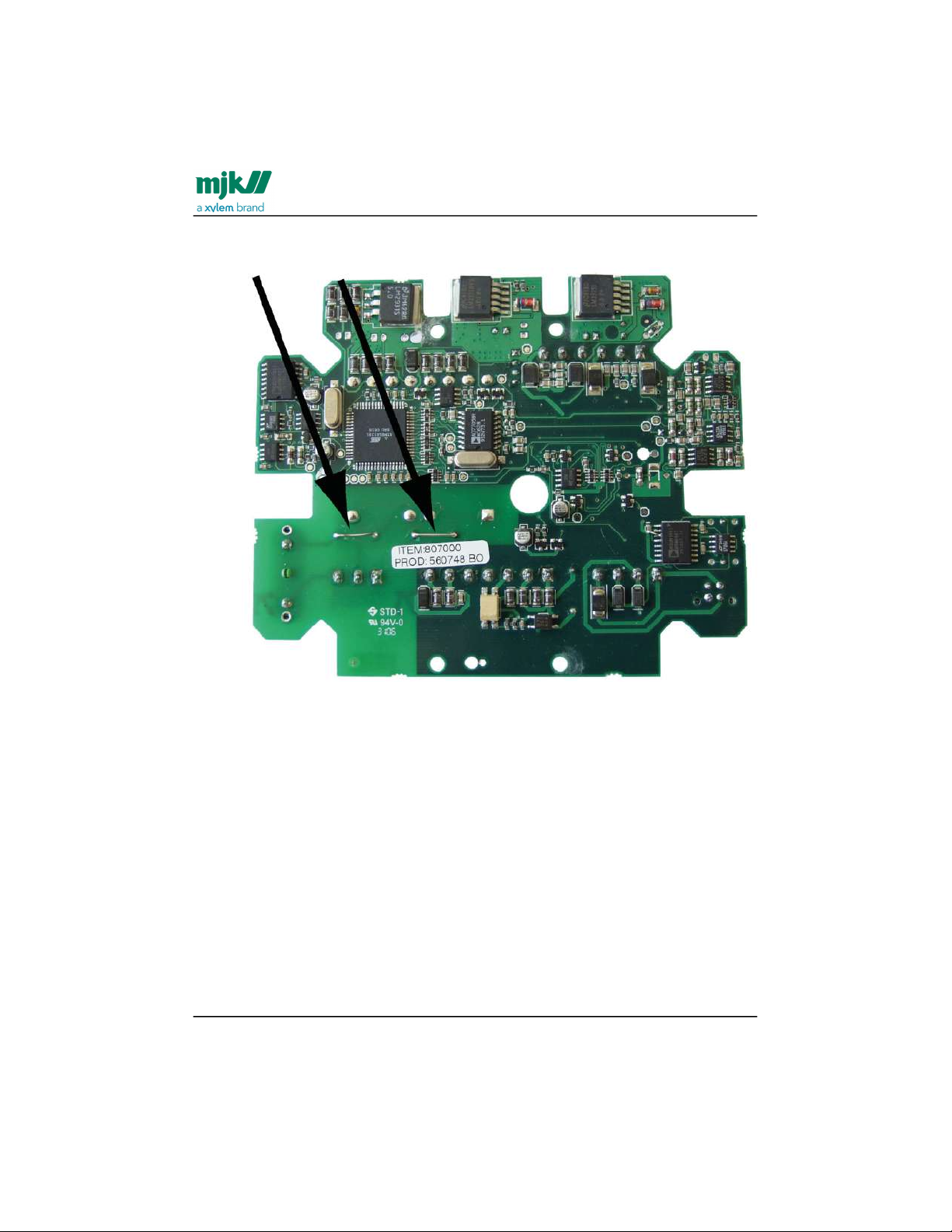
Look at the following picture to see where two new jumpers must be inserted
(115 V AC configuration):
Insert and solder two jumpers (wires) in the positions indicated by the arrows.
Turn around the PCB and replace the 63 mAT fuse on the right side with a 125
mAT fuse (or vice verse going from 115 VAC to 230 VAC).
Re-insert the PCB and re-assemble the flow meter (see also steps 4, 3, 2 and 1).
Find Quality Products Online at: [email protected]
www.GlobalTestSupply.com
Page 36
MagFlux® Series
EN 3.05 Version 2105
Flow converter /Analogue output
36
•
•
•
•
•
•
•
•
•
•
Analogue output
The analogue output is an active output with a max. load of 600Ω.
Analogue Output
Terminal Designation
AO + 4-20 mA
AO - 4-20 mA
The analogue output can be programmed for indication of:
Flow forward
Flow reverse
Forward and reverse (12 mA = 0)
Forward and reverse (4 mA = 0)
Not in use
See details in sections mA output(see page70), Flow forward(see page71), Flow reverse(see
page72), Forward & rev. (12mA=0)(see page73) and Forward & rev. (4mA=0)(see page74).
Digital outputs
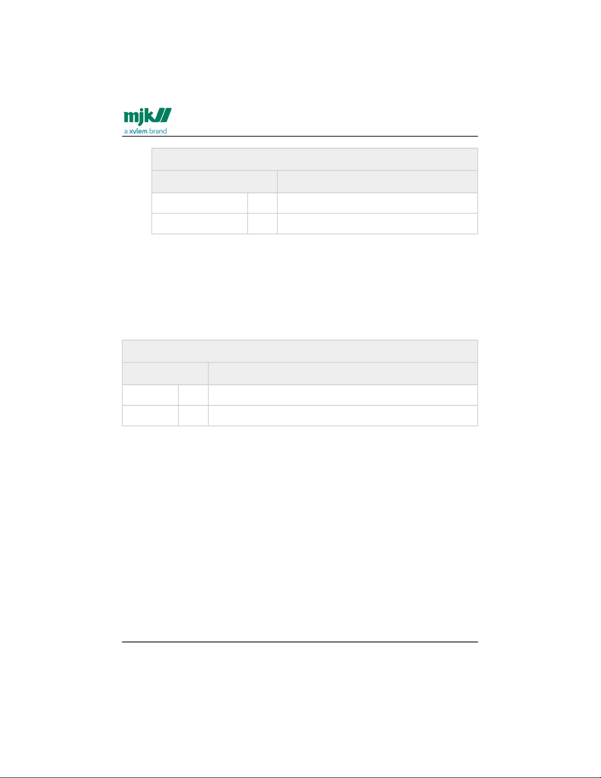
MagFlux® has two digital outputs - DO 1 with an opto (light triggered) relay and DO 2
with a mechanical relay.
They can both be programmed for the following functions:
high and low flow alarms
pulse output for counters R Totalizer Forward, Reverse and Sum.
batch 1 and batch 2 counters
empty pipe alarm
flow direction indication
Opto Relay (DO1)
Terminal Designation
DO 1 Com Max. 28 VAC/ 28 VDC /300 mA
DO 1 NO
Find Quality Products Online at: [email protected]
www.GlobalTestSupply.com
Page 37
MagFlux® Series
EN 3.05 Version 2105
Flow converter /Digital input
37
•
•
•
Mechanical Relay (DO2)
Terminal Designation
DO 2 Com Max. 28 VAC/ 28 VDC /500 mA
DO 2 NO
DO 1 shares the common terminal (Com) with DI.
See also application examples in Appendix G. Digital input/output
connections(see page151).
Digital input
MagFlux® has one digital input which is activated with a voltage higher than 10 V DC
and deactivated with a voltage lower than 5 V DC.
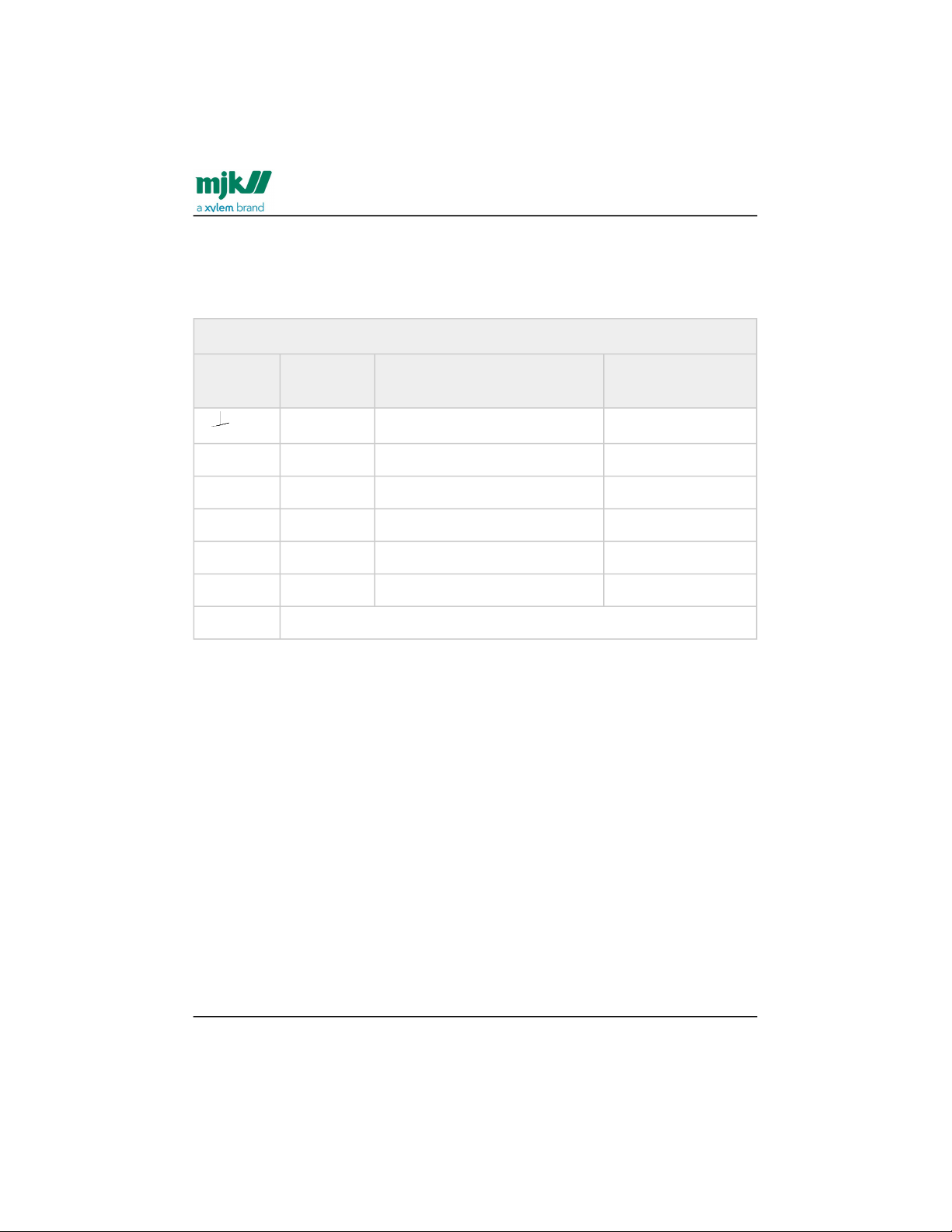
Digital Input
Terminal Designation
DI Com
DI Max. 30 V DC
The digital input (DI) can be programmed for the following functions:
start and pause batch 1 and batch 2 counters
reset counters R Totalizer Forward and Reverse
reset counter R Totalizer Sum
DI shares the common terminal (Com) with DO 1.
See also application examples in Appendix G. Digital input/output connections(see
page151).
Find Quality Products Online at: [email protected]
www.GlobalTestSupply.com
Page 38
MagFlux® Series
EN 3.05 Version 2105
Flow converter /Local (compact) flow sensor
38
Local (compact) flow sensor
Connect the compact (local) flow sensor to the flow converter with the wires coming
from the flow sensor as shown below.
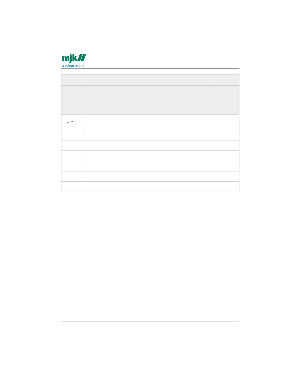
Compact Flow Sensor
Terminal Signal Designation Colour from
sensor
1
Liquid GND Built-in liquid ground electrode Black/shield
2 E1 Electrode Red
3 E2 Electrode White
4 GND Ground Black
5 L1 Coil Blue
6 L2 Coil Brown
7, 8 and 9 not used
Remote flow sensor
Connect the remote flow sensor to the flow converter with the sensor cable.
Important: Do not use other cable types!
Important: Terminals 1 and 4 must be shunted!
The extension cable length between converter and sensor must under normal
circumstances not exceed 50 meters. Power lines running in parallel and noisy
environments may reduce the max. length to less than 50 meters. Consult us for advice
and guidance.
Find Quality Products Online at: [email protected]
www.GlobalTestSupply.com
Page 39
MagFlux® Series
EN 3.05 Version 2105
Flow converter /Remote flow sensor
39
Remote Flow Sensor MagFlux® Sensor Cable
TerminalSignal Desig- nation Color before
March2011
Color
from
March
2011
1
Liquid
GND
Shield - -
2 E1 Wire pair no. 1 Red Red
3 E2 Wire pair no. 1 White White
4 GND Wire pair no. 3 Black Black
5 L1 Wire pair no. 2 Green Blue
6 L2 Wire pair no. 2 White Brown
7, 8 and 9 not used
Find Quality Products Online at: [email protected]
www.GlobalTestSupply.com
Page 40
MagFlux® Series
EN 3.05 Version 2105
Flow converter /Converter connection board - local
40
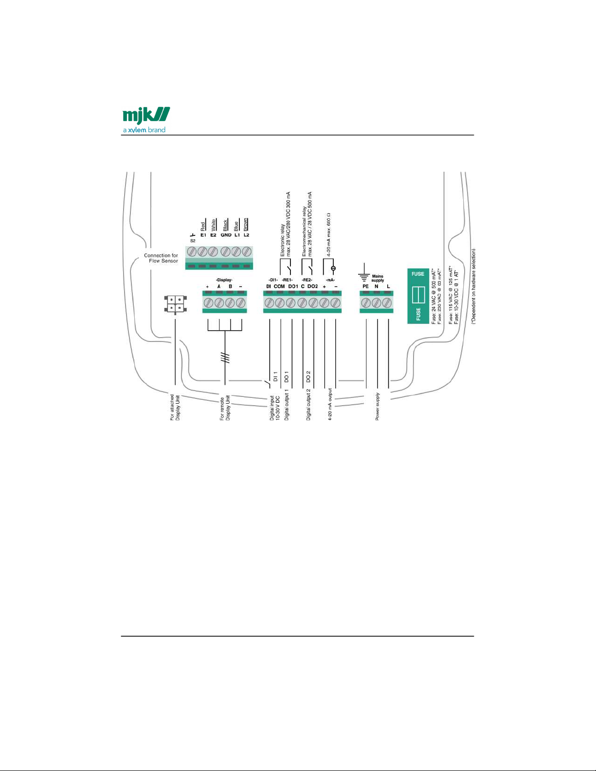
Converter connection board - local
Find Quality Products Online at: [email protected]
www.GlobalTestSupply.com
Page 41
MagFlux® Series
EN 3.05 Version 2105
Flow converter /MJK Connection board - remotely mounted converter
41
MJK Connection board - remotely mounted converter
Note! Before March 2011, the blue wire for terminal 5 was green and the brown wire for
terminal 6 was white.
Note! After November 2018, the latch between terminal A, 1 and 4 is build into the PCB.
Find Quality Products Online at: [email protected]
www.GlobalTestSupply.com
Page 42
MagFlux® Series
EN 3.05 Version 2105
System configuration examples /MJK compact converter and display unit on flow
sensor
42
•
•
•
•
•
System configuration examples
MJK compact converter and display unit on flow sensor
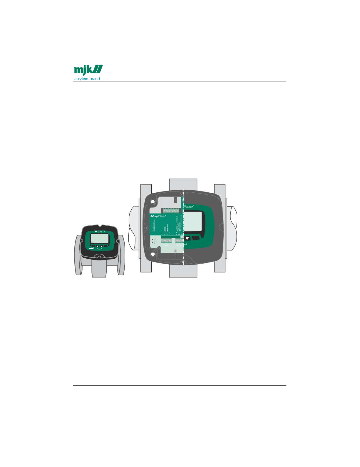
Configuration: The MagFlux® converter and display unit is mounted directly on the
MagFlux® flow sensor.
Order numbers for this configuration:
207xxx MagFlux® Flow Sensor
207920 MagFlux® Converter with display unit for sensor mounting
207920 consists of:
207940 Display Unit
807000 Converter PCB
500214 Field Cabinet bottom part for sensor mounting
MJK remote converter with connection box on flow sensor
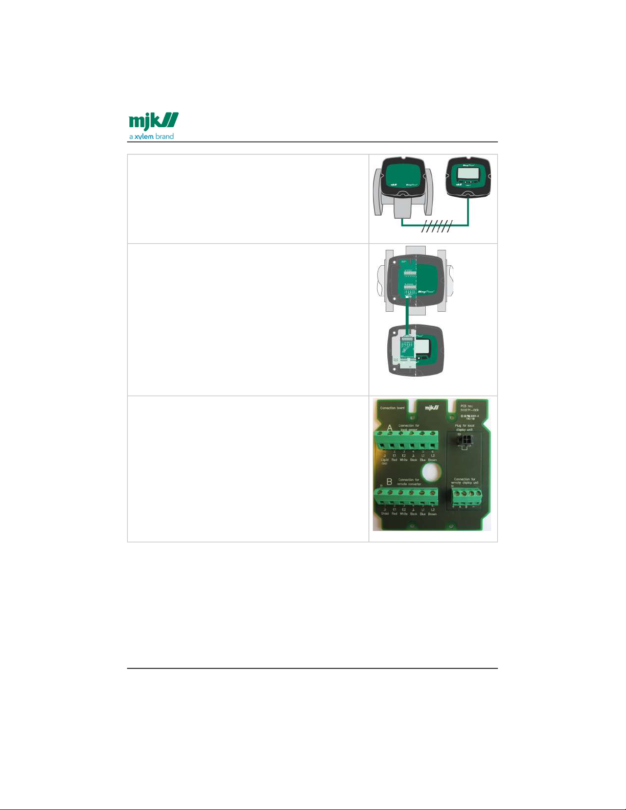
Configuration: The MagFlux® converter and display unit is remote mounted, for
example when the sensor must be IP 68 drown-proof.
.
Find Quality Products Online at: [email protected]
www.GlobalTestSupply.com
Page 43
MagFlux® Series
EN 3.05 Version 2105
System configuration examples /Wiring schematic #1
43
•
•
•
•
•
•
•
•
•
Order numbers for this configuration:
207xxx MagFlux® Flow Sensor
207925 MagFlux® Converter with Display Unit
for wall mounting
691080 MagFlux® Sensor cable
579035 MagFlux® Gel Potting Kit IP68
207925 consists of:
207940 Display Unit
807020 MagFlux connection PCB (see picture
below)
820050 Blind Lid
800070 Cabinet bottom part for sensor
mounting
800075 Cabinet bottom part for wall mounting
PCB
Wiring schematic #1
Wiring schematic for MJK remote converter with connection box on flow sensor(see
page42).
Find Quality Products Online at: [email protected]
www.GlobalTestSupply.com
Page 44
MagFlux® Series
EN 3.05 Version 2105
System configuration examples /MJK remote display and multiple converters wiring
44
Flow sensor
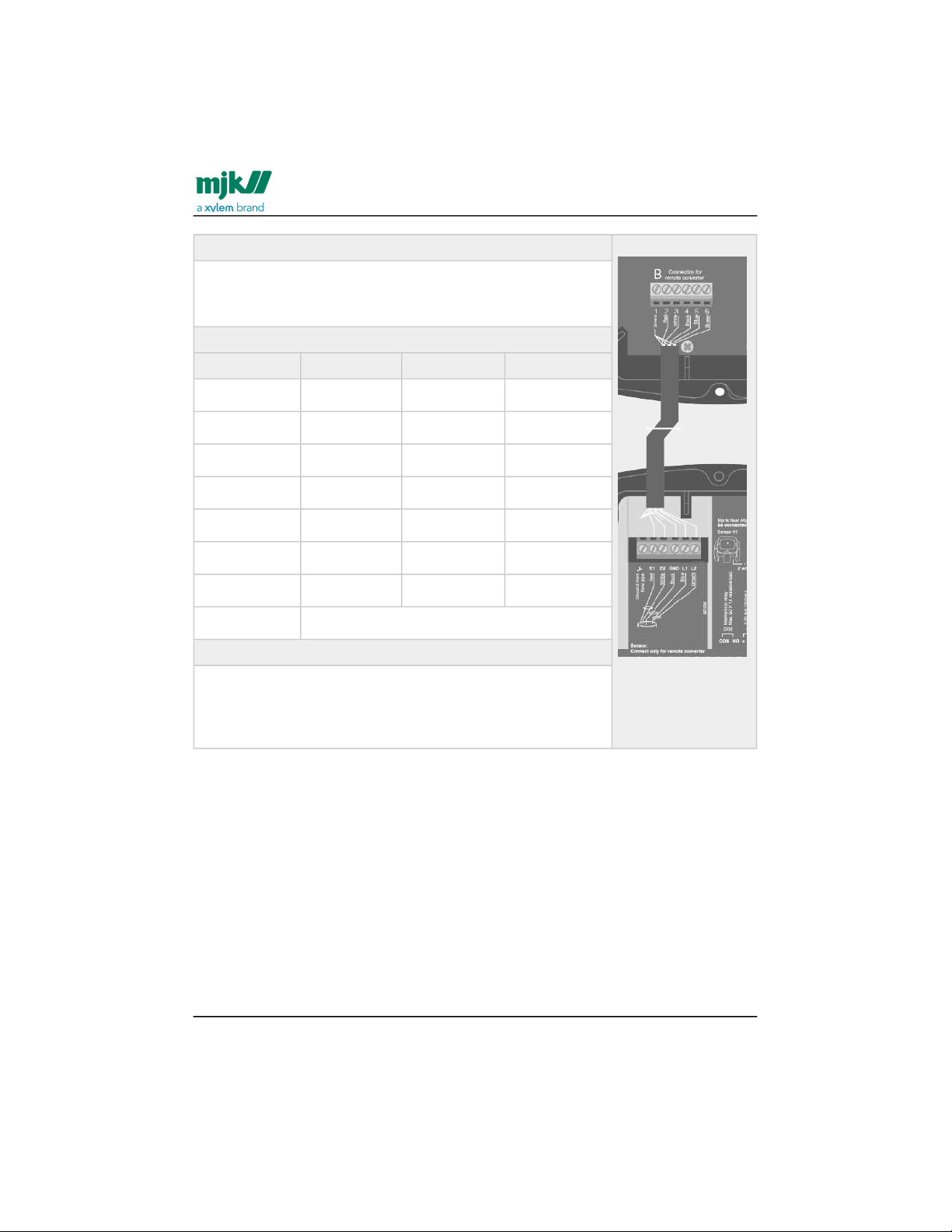
Connect one end of the cable to the flow sensor as described in
the table below. All three shields are twisted and connected in
slot 1. The white lead in pair no. 3 is not used.
B Connection for remote converter
Terminal Signal Wire Color
1 GND Shield -
2 E1 Pair 1 Red
3 E2 Pair 1 White
4 GND Pair 3 Black
- - Pair 3 -
5 L1 Pair 2 Blue
6 L2 Pair 2 Brown
7,8,9 Not used
Remote converter (and display unit)
Connect the other end of the cable to the remote converter as
shown to the right. The 1 Shield lead goes into Ground from
flow pipe, the 2 Red lead goes into E1 Red, the 3 White lead
into E2 White, and so on.
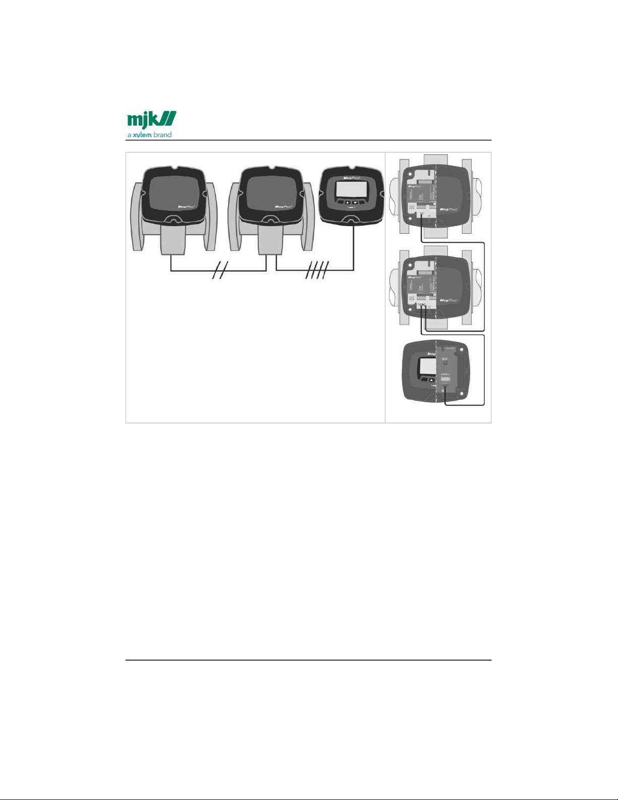
MJK remote display and multiple converters wiring
Configuration: Two locally mounted MagFlux® flow sensors and converters with blind
lid and one remotely mounted display unit.
The communication between the sensors and the display unit is executed on shielded
twisted 2- and 4-wire cables using the Modbus® communication protocol on RS-485.
Find Quality Products Online at: [email protected]
www.GlobalTestSupply.com
Page 45
MagFlux® Series
EN 3.05 Version 2105
System configuration examples /Wiring schematic #2
45
•
•
•
•
•
•
•
•
Order numbers for this configuration:
207xxx MagFlux® Flow Sensor (2 pcs.)
207925 MagFlux® Converter with Display Unit for wall
mounting
207910 MagFlux® Converter w/o display sensor
mounting, 230/115VAC
207925 consists of:
207940 Display Unit
807021 MagFlux® connection PCB
820050 Blind lid
800070 Cabinet bottom part for sensor mounting
500210 Cabinet bottom part for wall mounting
Note: The total maximum cable length for the 2- and 4-wire shielded twisted cables is
1000 meters.
Wiring schematic #2
Wiring schematic for MJK remote display and multiple converters wiring(see page44).
Find Quality Products Online at: [email protected]
www.GlobalTestSupply.com
Page 46
MagFlux® Series
EN 3.05 Version 2105
System configuration examples /Wiring schematic #2
46
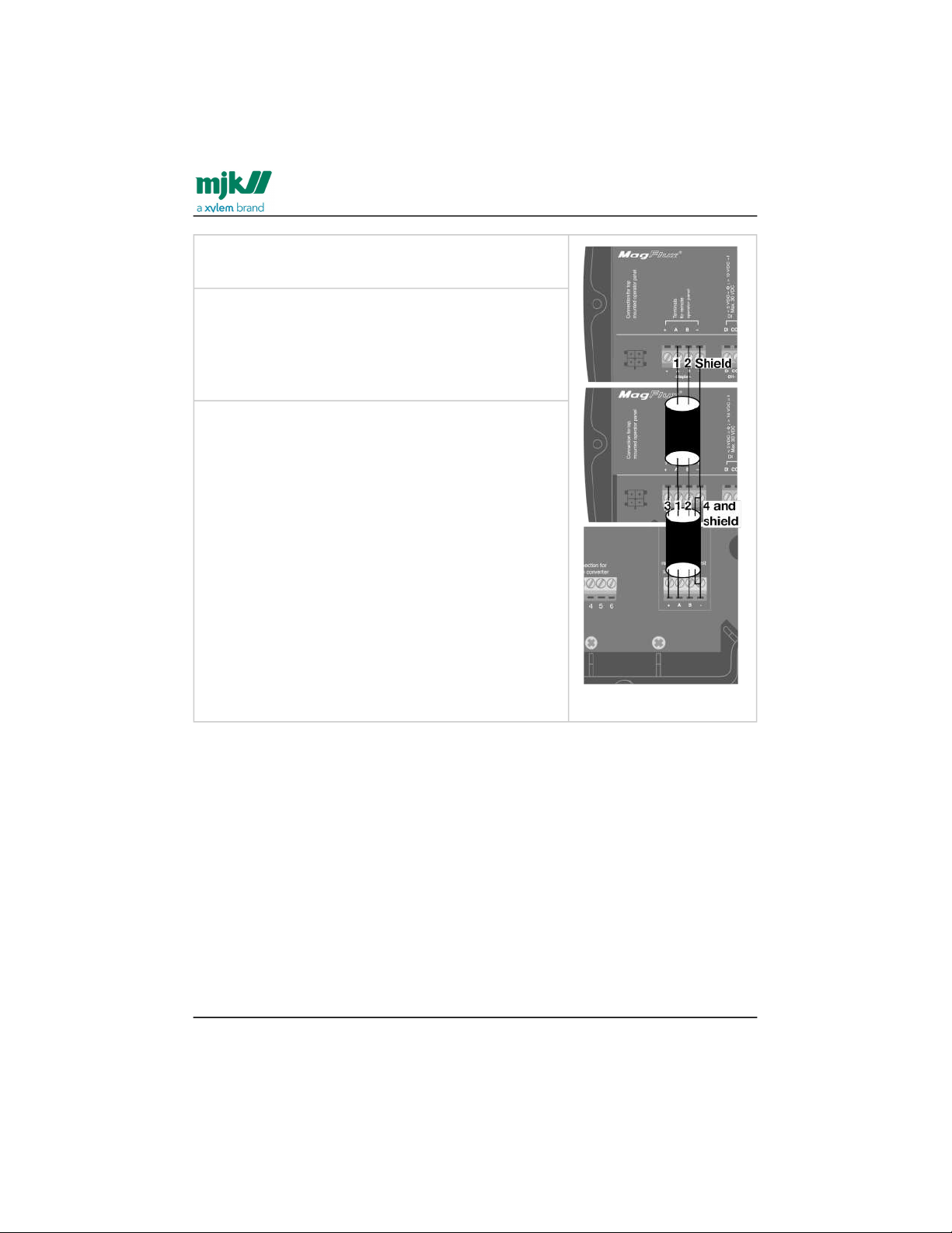
Local flow sensor 1
2-wire twisted shield cable: Connect lead 1 to slot A,
lead 2 to slot B and shield to slot -.
Local flow sensor 2
2-wire twisted shield cable: Connect lead 1 to slot A,
lead 2 to slot B and twisted shield to slot -.
4-wire twisted shield cable: Connect lead 1 to slot A,
lead 2 to slot B, lead 3 to slot + and lead 4 and twisted
shield to slot -.
Remote display unit
4-wire twisted shield cable: Connect lead 1 to slot A,
lead 2 to slot B, lead 3 to slot + and lead 4 and twisted
shield to slot -.
Find Quality Products Online at: [email protected]
www.GlobalTestSupply.com
Page 47

MagFlux® Series
EN 3.05 Version 2105
Startup /MJK initial checks
47
1.
2.
3.
4.
5.
1.
2.
3.
1.
2.
1.
2.
3.
Startup
MJK initial checks
Before switching power on for the MagFlux®, the following steps must be checked.
The local mains power supply voltage corresponds to the voltage printed on the
identification label of the MagFlux® flow converter.
All electrical connections are made in accordance with the electrical connection
diagram shown in Converter connection board - remote(see page41).
All terminal screws are tightened.
All cable glands are tightly secured.
All grounding connections are made in accordance with the instructions in
Potential equalization and grounding(see page28).
Initial flow measurement
Make sure that the MagFlux® flow sensor is completely filled with liquid.
Turn on power to the MagFlux® flow converter and wait one minute.
Verify or enter the calibration code of the MagFlux® flow sensor in the Converter
Setup/Service Menu/Sensor Calibration Code menu (see also Service
menu(see page97)). If the entered calibration code is incorrect read the correct
calibration code on the converter as explained in section on product
identification.
Flow direction check
Allow free flow through the sensor.
Check on the MagFlux® display unit screen that the flow value increases. If the
value goes negative, check that the Flow direction option(see page92) is set
correctly and/or check the electrical connections on the flow sensor.
Language selection
The default display language is English (GB). If another language is required,
proceed with step 2.
From the Main Menu, select Display Setup(see page108).
Select Language(see page109) and chose the required language.
Find Quality Products Online at: [email protected]
www.GlobalTestSupply.com
Page 48
MagFlux® Series
EN 3.05 Version 2105
Startup /MJK display read-out, one connected unit
48
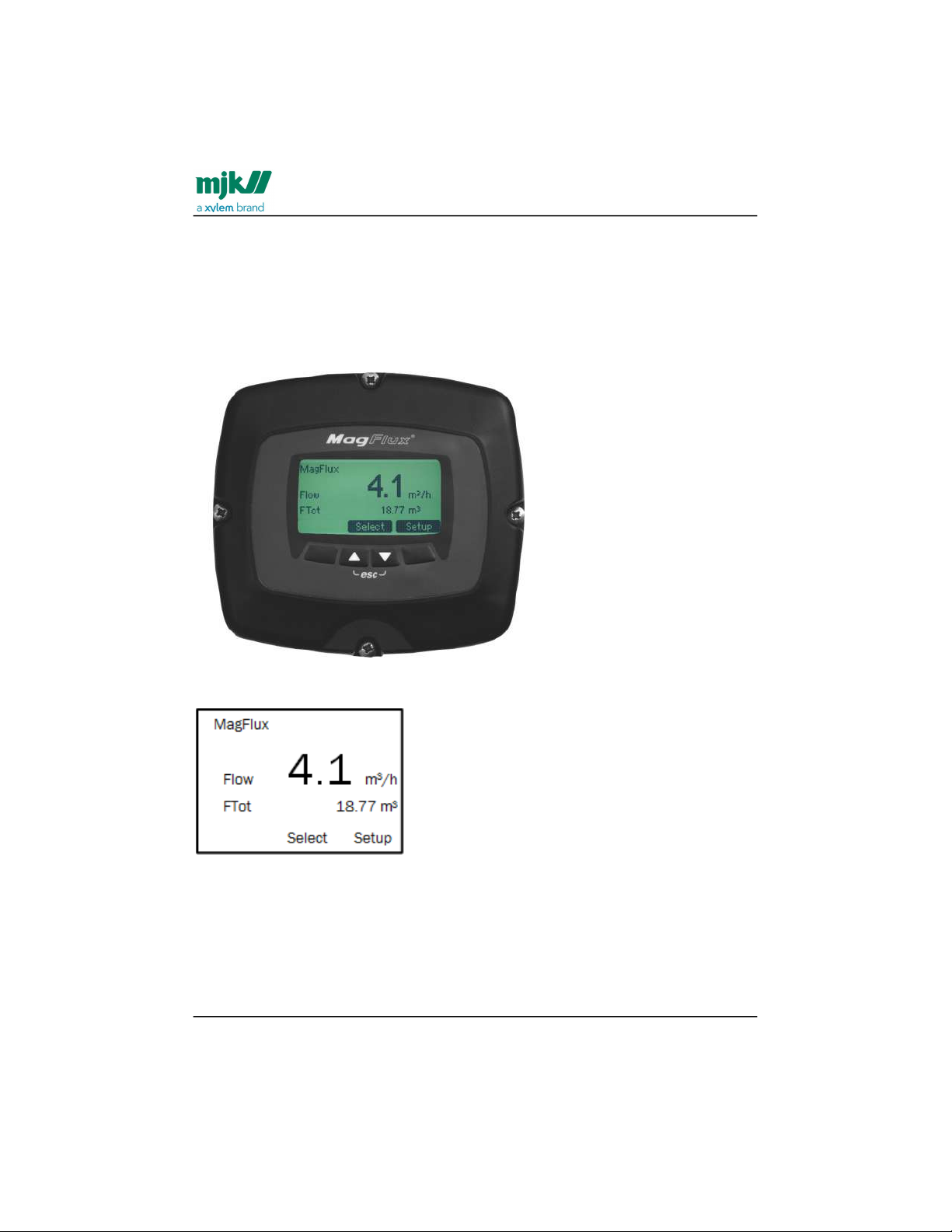
MJK display read-out, one connected unit
All MagFlux® display read-outs are illustrated and described in this manual. Section
MagFlux® menus(see page53) gives a detailed description of the displays shown during
setup, configuration and normal operation. A 5-line LCD screen displays symbols and
the actual status during setup, configuration, servicing and normal operation (see also
Specify main screen(see page54)).
The display shown above will, in the remaining parts of this manual, be stylized to
appear like this:
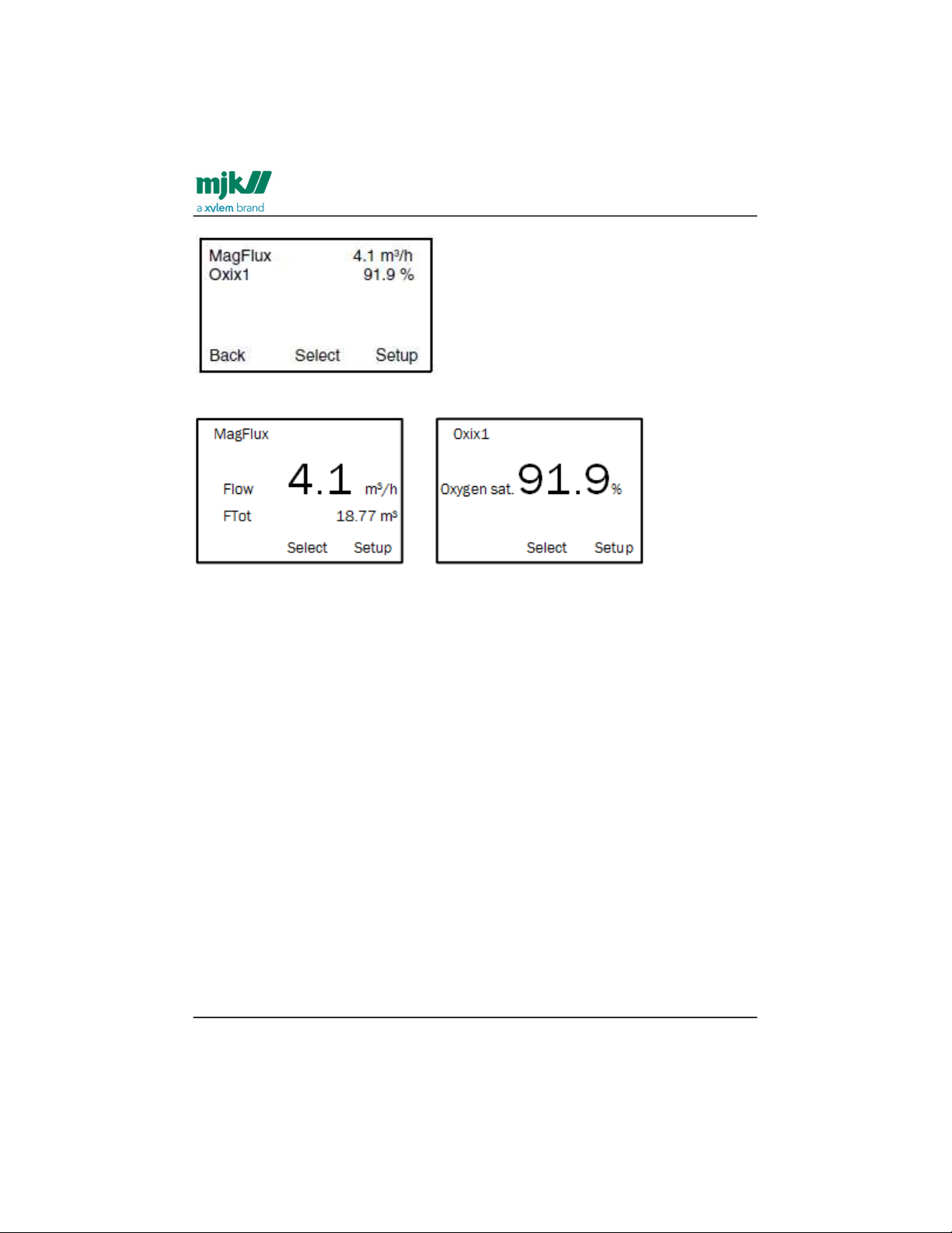
Display read-out, several connected units
When several units are interconnected, for example an Oxix® dissolved oxygen
transmitter and MagFlux® flow meter with different names and Modbus ID numbers, a
Display Overview Menu is available at top level (press Back repeatedly):
Find Quality Products Online at: [email protected]
www.GlobalTestSupply.com
Page 49
MagFlux® Series
EN 3.05 Version 2105
Startup /MJK display keys
49
All connected units are displayed and sorted by their ID numbers, and consequently
each unit can be selected and set up as required:
or
Important: More connected units can only by managed as described above if each unit
has been assigned a unique name and Modbus ID number. See Modbus(see page111) for
details.
MJK display keys
The keys and the soft keys (variable key functions determined by the display firmware)
are used for initial programming and normal operation of the flow meter. The function(s)
of the four available keys is displayed at the bottom of the display. The symbols and
actual functions are described in detail in the sections that describe the individual
menus.
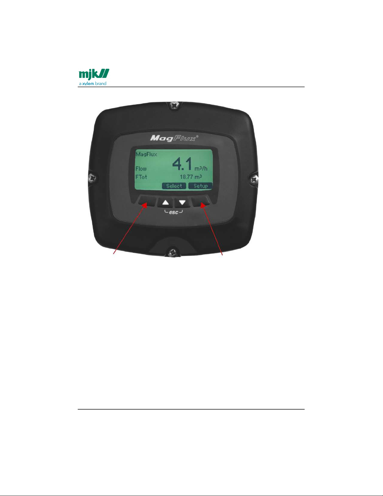
Contrast adjustment
Adjust the display contrast by pressing the two outmost keys simultaneously (indicated
by the keys) and press the up/down keys as required.
Find Quality Products Online at: [email protected]
www.GlobalTestSupply.com
Page 50
MagFlux® Series
EN 3.05 Version 2105
Startup /Initial setup
50
Save the new setting by pressing the two outmost keys simultaneously.
System reset
You can reset and refresh all system displays and key combinations by pressing all four
keys simultaneously. This feature is especially useful during for example a service call,
where the display language (Dutch, Danish, etc.) cannot be understood by the service
person. A system reset immediately sets the display language to (GB) English. The
system reset must not be confused with the ultimate Recover factory settings (see
Factory settings(see page116)) which deletes all local configurations/settings and replaces
them with default factory settings.
Initial setup
Initial setup is normally performed by our personnel and is required to get started with
the MagFlux® flow meter. A unique sensor calibration code provides the MagFlux® flow
converter with information about flow sensor number, nominal diameter and calibration
data.
If changes to the unique sensor calibration code are needed following physical
installation and initial setup, the Sensor Calibration Code menu must be addressed. A
Find Quality Products Online at: [email protected]
www.GlobalTestSupply.com
Page 51
MagFlux® Series
EN 3.05 Version 2105
Startup /Initial setup
51
1.
2.
password is not required to enter or change the sensor calibration code. Toggle
through the displayed digits with the right-arrow key when prompted for a password
and press OK.
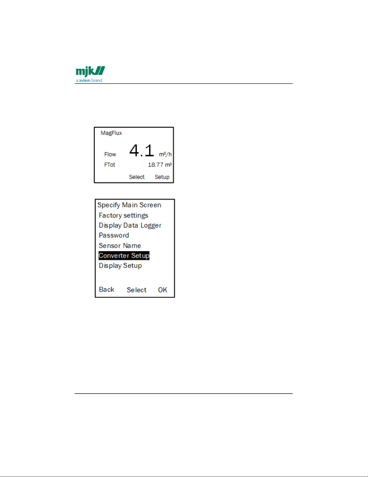
Press the Setup key on the display (see below) to enter the MagFlux® main
menu.
Press the up/down keys to highlight the required menu line (here: Converter
Setup) and press OK.
Find Quality Products Online at: [email protected]
www.GlobalTestSupply.com
Page 52
MagFlux® Series
EN 3.05 Version 2105
Startup /Initial setup
52
3.
4.
5.
1.
2.
3.
4.
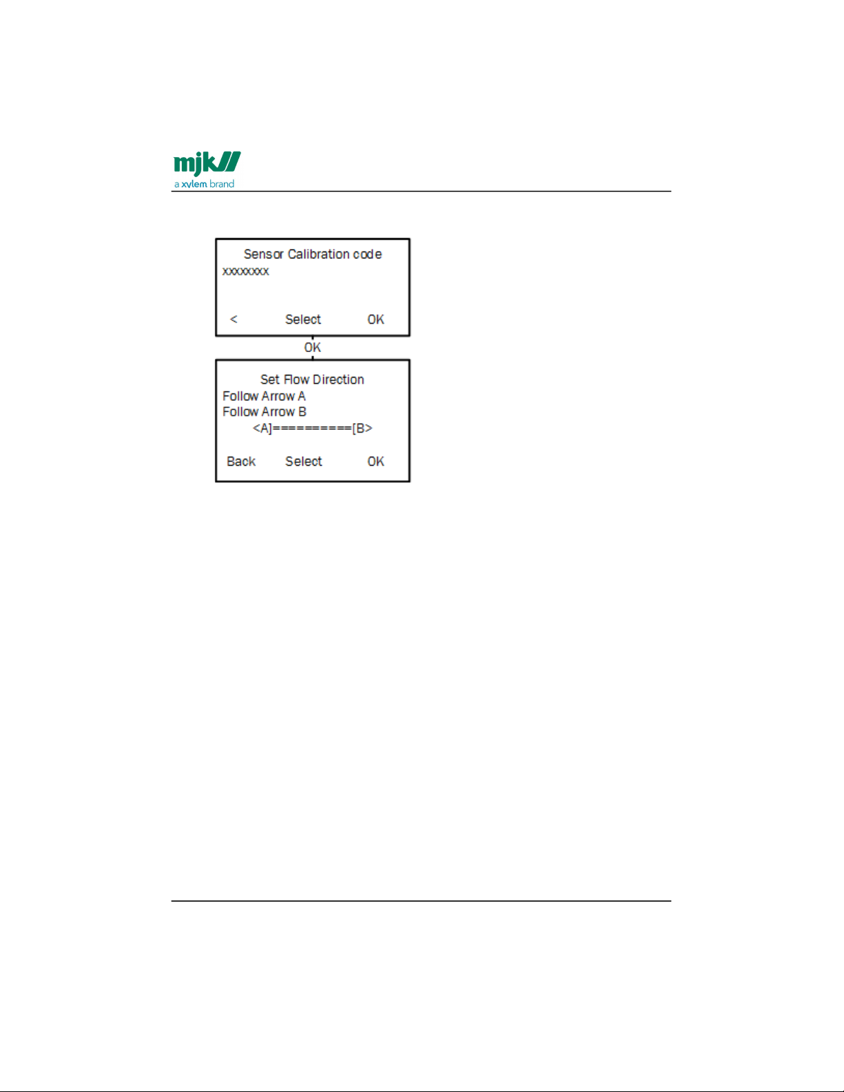
Select Service Menu, enter the password (the default password is "00000" (five
zeros) in Sensor Calibration Code.
Enter the calibration code read from the flow sensor label (or pass through or
change the displayed calibration code) and press OK. See also details regarding
the calibration code in the section on product identification.
Select the correct flow direction in the Set Flow Direction menu and press OK.
The MagFlux® is now configured with default settings and is ready for use.
Note: If the MagFlux® sensor has not been pre-configured from the factory with a sensor
calibration code, the calibration code procedure is somewhat different form the just
mentioned.
See the following steps to configure a non-configured sensor with a calibration code.
Apply power to the MagFlux® sensor.
When the Sensor Calibration Code menu appears (see above), enter the
calibration code read from the flow sensor label and press OK.
Select the correct flow direction from the Set Flow Direction menu and press
OK.
Sensor calibration code configuration is now finished, and you are returned to
the main menu.
Find Quality Products Online at: [email protected]
www.GlobalTestSupply.com
Page 53

MagFlux® Series
EN 3.05 Version 2105
MagFlux® menus /Main menu
53
1.
2.
3.
MagFlux® menus
All the MagFlux® menus and sub menus are shown and described in the following
sections. Continuous overviews of the menu and sub-menu structures are available from
the appendix.
Main menu
Press the Setup key on the MagFlux® display (see below) to enter the MagFlux®
main menu:
The MagFlux® main menu contains a number of sub menus:
Press the up/down keys to highlight the required menu line (here: Specify Main
Menu) and press OK.
Find Quality Products Online at: [email protected]
www.GlobalTestSupply.com
Page 54
MagFlux® Series
EN 3.05 Version 2105
MagFlux® menus /Specify main screen
54
1.
2.
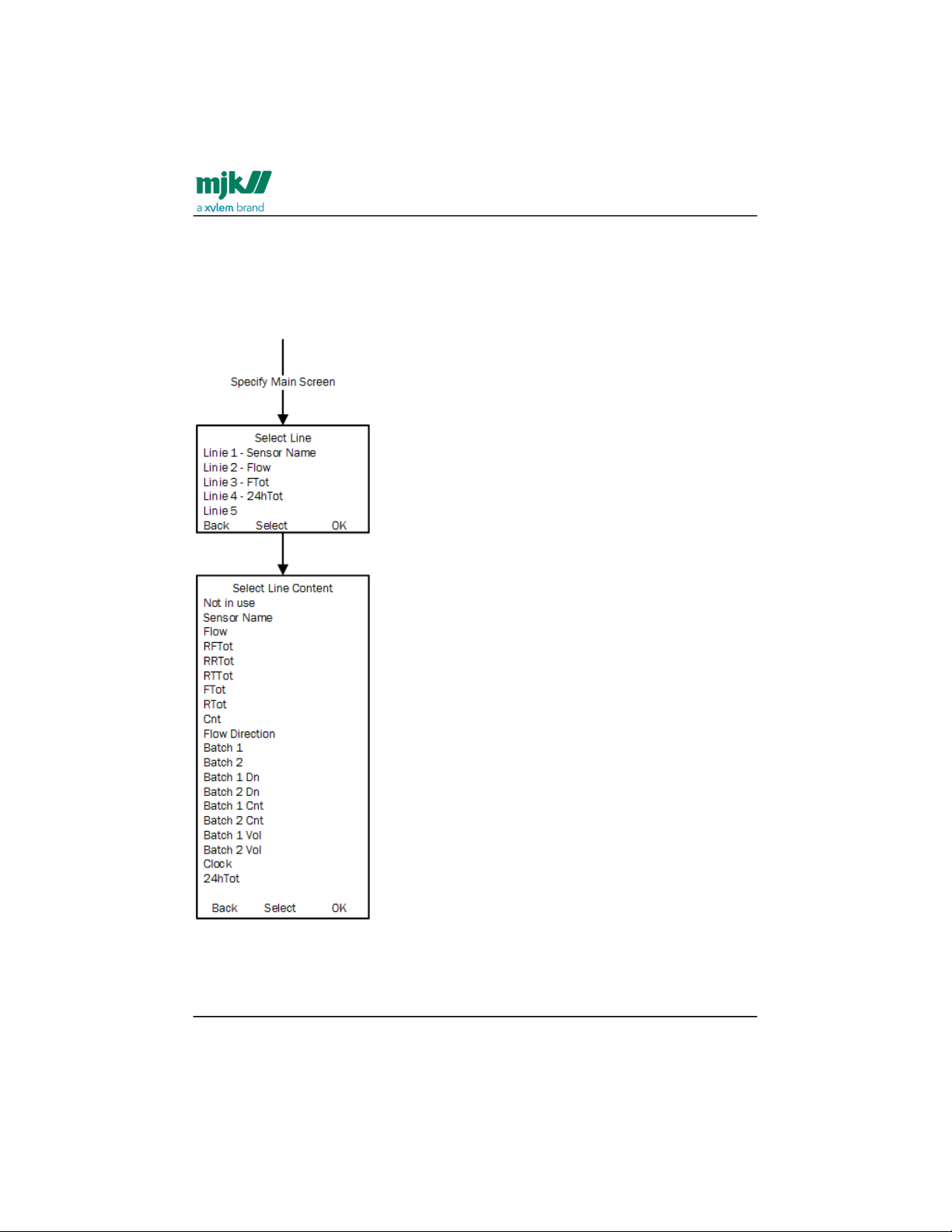
Specify main screen
The Specify Main Screen menu allows you to customize the MagFlux® display to suit
your requirements. You can add and remove the five available display lines and
configure them individually.
Press the up/down keys to highlight the required menu line and press OK.
Press the up/down keys to highlight the required option and press OK.
The available options are:
Find Quality Products Online at: [email protected]
www.GlobalTestSupply.com
Page 55

MagFlux® Series
EN 3.05 Version 2105
MagFlux® menus /MJK factory settings
55
•
•
•
•
•
•
•
•
•
•
•
•
•
•
•
•
•
•
•
•
Not in use: The line will not be used. The set free space will be used by the other
lines.
Sensor Name: The actual sensor name - for example, a number, a location, a
name or a function - will be displayed.
Note: The actual sensor name is defined later on in the Set Sensor Name menu,
see Set sensor name(see page64).
Flow: Actual flow rate (in units chosen in the menu for primary units).
RFTot: Resettable Forward Totalizer counter 32bit (unit L) 4 294 967 295 L
RRTot: Resettable Reverse Totalizer counter 32bit (unit L) 4 294 967 295 L
RTTot: Resettable Total Totalizer counter 32bit (unit L) 2 147 483 647 L (+/- half
of Tot)
FTot: Forward Totalizer counter 64bit (unit mm3) 18 446 744 073 709 551 615
mm
3
RTot: Reverse Totalizer counter 64bit (unit mm3) 18 446 744 073 709 551 615
mm
3
Cnt: Totalizer sum Counter 64bit (unit mm3) 9 223 372 036 854 775 807 mm
3
(+/- half of Tot)
Flow Direction: Flow direction A or B will be displayed
Batch 1: Timer for batch volume 1
Batch 2: Timer for batch volume 2
Batch 1 DN: Displays the missing amount of Batch volume 1 (DN = down)
Batch 2 DN: Displays the missing amount of Batch volume 2 (DN = down)
Batch 1Cnt: Batch 1 Counts (number of batches)
Batch 2 Cnt : Batch 2 Counts (number of batches)
Batch 1 Vol: Batch 1 Volume
Batch 2 Vol: Batch 2 Volume
Clock: Time and date
24hTot: The total flow for 1 day (24 hours) logged at midnight (12 PM).
The size of the display lines will automatically increase or decrease as the number of
display lines is removed or added to maximize the field of view for the measured values.
MJK factory settings
The Factory Settings menu resets the display to default settings, to metric settings or to
US settings.
Note: The converter settings are not changed from this menu. Converter settings are
covered in Converter setup(see page65).
Find Quality Products Online at: [email protected]
www.GlobalTestSupply.com
Page 56
MagFlux® Series
EN 3.05 Version 2105
MagFlux® menus /MJK factory settings
56
1.
2.
•
•
•
•
•
•
•
•
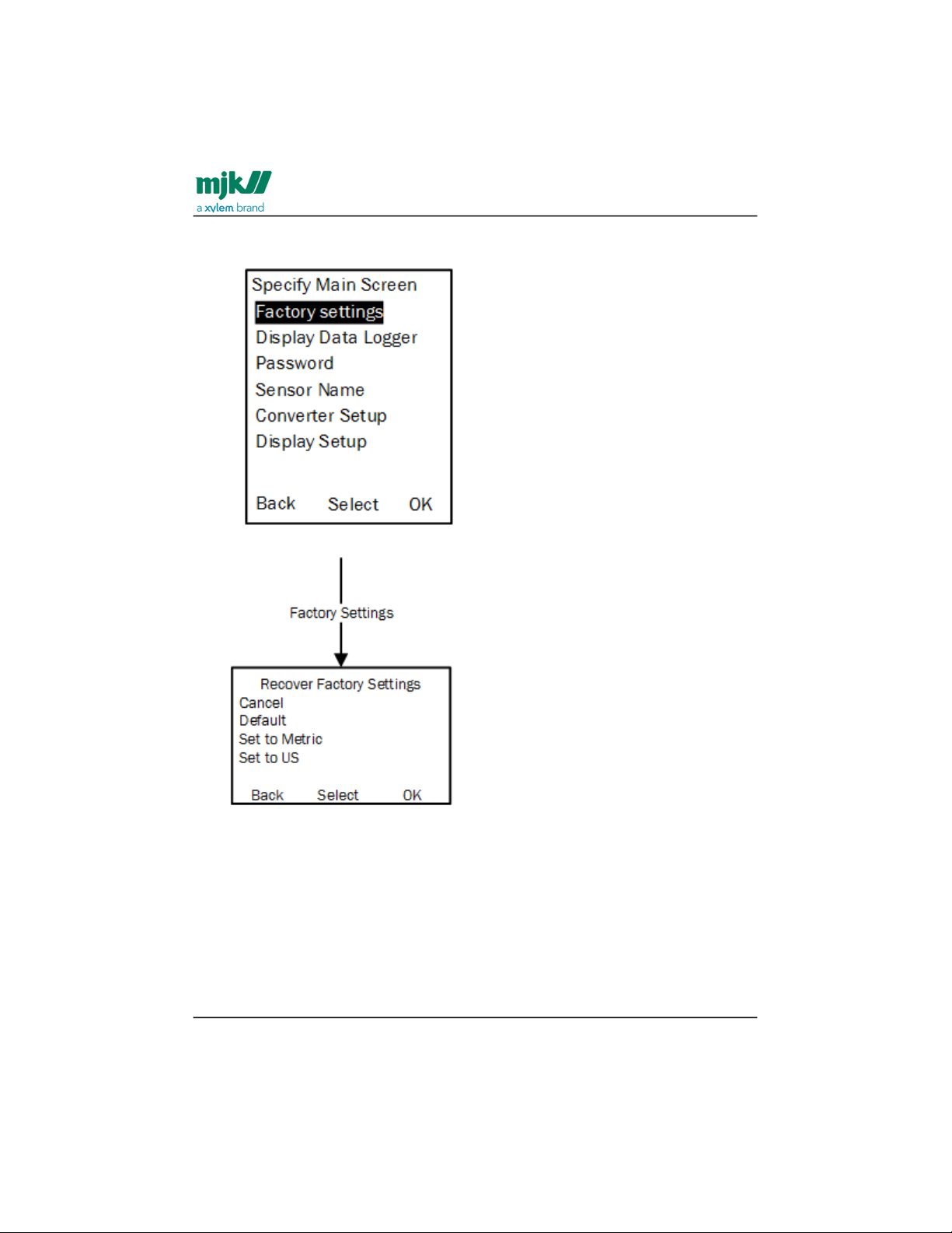
Press the up/down keys to highlight the required menu line (here: Factory
Settings) and press OK.
Press the up/down keys to highlight the required option and press OK.
The available options are:
Cancel: Exit the menu without changes.
Default: When Default is selected, the following settings are not affected and
remain as chosen by the user:
Sensor Name
Device ID
Flow Direction
DN, size
Calibration
Calibration Code
Find Quality Products Online at: [email protected]
www.GlobalTestSupply.com
Page 57
MagFlux® Series
EN 3.05 Version 2105
MagFlux® menus /MJK factory settings
57
•
•
Per default, the in- and outputs are not activated from the factory. Activate the in- and
outputs by configuring the functions with, for example, the default values shown in the
following tables:
MagFlux Default DI/DO Settings
MagFlux Default 20 mA Settings
MagFlux Default DI/DO Settings
Digital Output 1 (opto)
- DO1
Digital Output 2
(mech.) - DO2
Digital Input - DI
Counter R Totalizer
Forward
Counter R Totalizer
Forward
RESET R Totalizer
Forward
Counter R Totalizer
Reverse
Counter R Totalizer
Reverse
RESET R Totalizer
Reverse
R Totalizer Sum R Totalizer Sum RESET R Totalizer Sum
Batch Counter 1 Batch Counter 1
Start / Pause Batch
counter 1
Batch Counter 2 Batch Counter 2
Start / Pause Batch
counter 2
Low Flow Low Flow
High Flow High Flow
Flow Direction Flow Direction
Empty Pipe Empty Pipe
Note: The same function can not be on assigned to both relays.
Find Quality Products Online at: [email protected]
www.GlobalTestSupply.com
Page 58
MagFlux® Series
EN 3.05 Version 2105
MagFlux® menus /MJK factory settings
58
MagFlux Default 20 mA Settings
Metric US
DN [mm]
Flow [m3/h]
Size Flow [GPM]
15 5 ½" 30
20 10 3/4" 50
25 20 1" 75
32 30 1¼" 100
40 50 1½" 200
50 75 2" 300
65 100 2½" 500
80 200 3" 800
100 300 4" 1000
125 400 5" 2000
150 600 6" 3000
200 1000 8" 5000
250 2000 10" 7700
300 2500 12" 10000
350 3000 14" 10000
400 4500 16" 20000
450 6000 18" 25000
500 7000 20" 30000
600 10000 24" 40000
Find Quality Products Online at: [email protected]
www.GlobalTestSupply.com
Page 59
MagFlux® Series
EN 3.05 Version 2105
MagFlux® menus /MJK factory settings
59
•
•
MagFlux Default 20 mA Settings
Metric US
DN [mm]
Flow [m3/h]
Size Flow [GPM]
700 15000 28" 60000
800 20000 32" 80000
900 25000 36" 100000
1000 30000 40" 100000
1200 40000 48" 200000
Set to metric: All converter-related units can be set to the following units (default
values in bold and italics):
Flow
Unit
Totalizers
m3/sec
RFTot RRTot RSTot FTot RTot Cnt
l/sec l l l
l l l
l/min hl hl hl hl hl hl
l/h kl kl kl kl kl kl
m3/h
m
3
m
3
m
3
m
3
m
3
m
3
Set to US: All converter-related units can be set to the following units (default
values bold and in italics)
Flow
Unit
Totalizers
ft3/h
RFTot RRTot RSTot FTot RTot Cnt
MGD
ft
3
ft
3
ft
3
ft
3
ft
3
ft
3
GPM
gal gal gal
gal gal gal
MG MG MG MG MG MG
Find Quality Products Online at: [email protected]
www.GlobalTestSupply.com
Page 60
MagFlux® Series
EN 3.05 Version 2105
MagFlux® menus /Data logger
60
1.
2.
3.
•
•
•
Data logger
MagFlux® provides a data logger with a capacity of approx. 345.000 entry points. See
Appendix E. about test certificate for examples and descriptions of log files.
The data logger operates after the FIFO principle (First In, First Out). If the data logger is
full and new data are coming in, the oldest data are discarded.
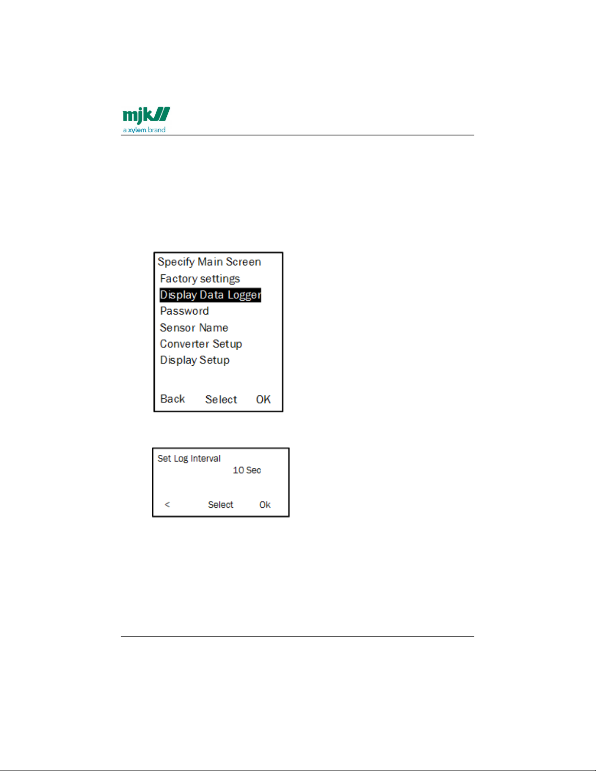
Press the up/down keys to highlight the required menu line (here: Display Data
Logger) and press OK.
Select the digits one by one with the left/right keys and set the values with the
up/down keys.
Continue until all digits have been set and press OK. The log interval can be set
in intervals from 10 sec. up to 9999 sec.
The data log contains:
Date
Time
Flow values
In case of a power failure, the MagFlux® data logger continues when power returns. If
more MagFlux® converters are connected to one MagFlux® display unit, each MagFlux®
Find Quality Products Online at: [email protected]
www.GlobalTestSupply.com
Page 61
MagFlux® Series
EN 3.05 Version 2105
MagFlux® menus /Data logger
61
converter has its own individual log interval and can be sorted. All MagFlux® converters
share the same memory of 345.000 entry points.
The log data can be shown on the MagFlux® display unit or be stored in an external CSV
file. TheField Link software is needed for transfer of data into CSV file format via the
USB port in the MagFlux® display unit. The format can be read in, for example
Microsoft® Excel®, (see Appendix B. about Field Link software for details).
An example of the log capacity of one sensor versus the time interval is shown in the
following table.
Log interval Log capacity
Seconds Minutes Hours Days
10 - 958 39
30 - 2875 119
- 1 5750 239
- 5 28750 1198
- 10 57500 2395
- 30 172500 7187
- 60 345000 14375
Graph display
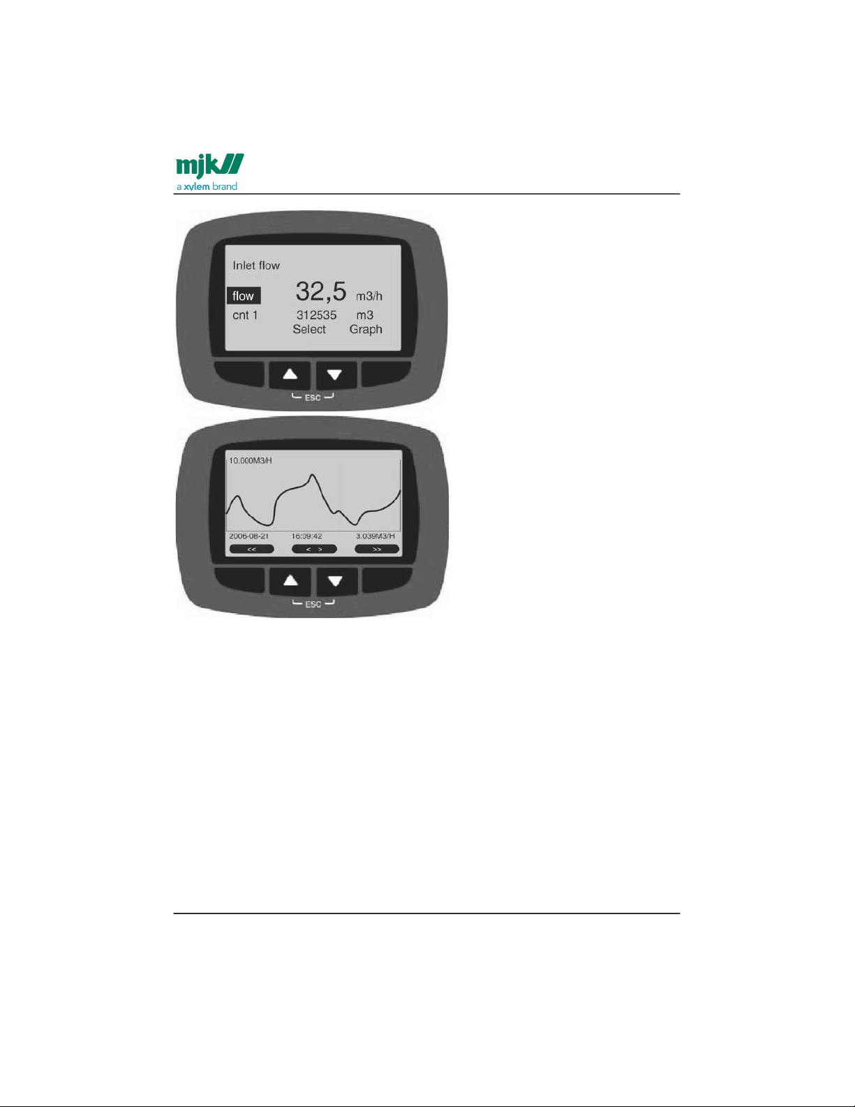
The content of the Data Logger can be displayed on the MagFlux® display unit by
pressing the up/down keys simultaneously (esc), highlighting Flow and selecting
Graph.
Find Quality Products Online at: [email protected]
www.GlobalTestSupply.com
Page 62
MagFlux® Series
EN 3.05 Version 2105
MagFlux® menus /Password
62
The MagFlux® display unit then shows the Graph screen. To return to the Main Menu,
select esc by pressing the up/down keys simultaneously.
The Y axis is automatically scaled according to the Q
max
of the mA output.
Double-arrow keys jump forward and backward one screen frame at a time. Singlearrow keys move the cursor forward and backward on the screen. The actual values at
the cursor position is shown at the bottom of the screen.
Password
A password provides (and prevents) access to all settings in the display and converter
unit. The code consists of a numeric 5-digit code between 0 and 65535. If your current
password is lost or forgotten, the password protection can be overruled with the code
01750.
Find Quality Products Online at: [email protected]
www.GlobalTestSupply.com
Page 63
MagFlux® Series
EN 3.05 Version 2105
MagFlux® menus /Password
63
1.
2.
•
•
•
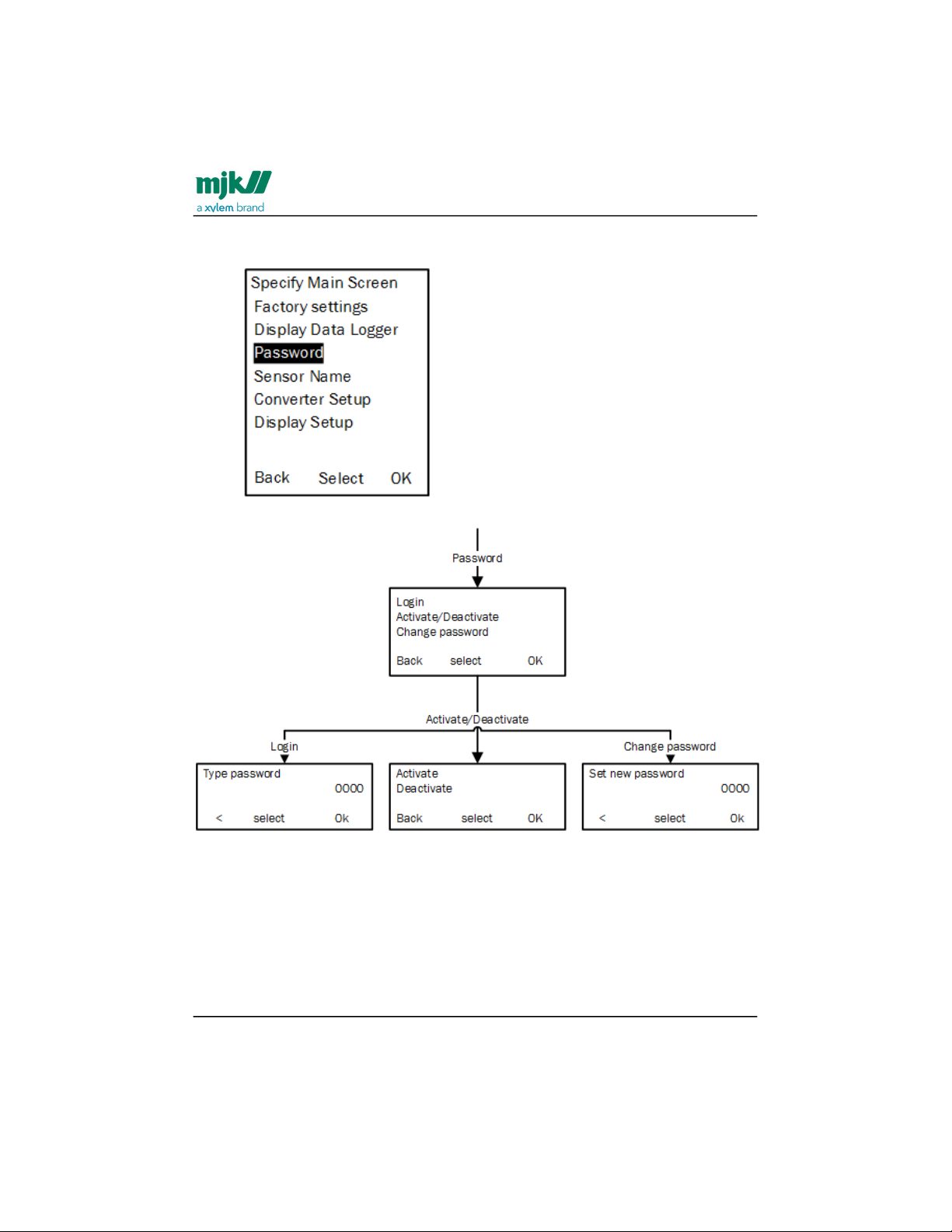
Press the up/down keys to highlight the required menu line (here: Password)
and press OK.
Press the up/down keys to highlight the required menu lineand press OK.
The available options are:
Login: Select the digits one by one with the left/right keys and set the values with
the up/down keys and press OK.
Activate/Deactivate: Write protection. Selecting Activate means that a
password must be entered to change vital settings. Deactivate disables
password protection. If your current password is lost or forgotten, the password
protection can be overruled with the code 01750.
Set new password: The selected 5-digit password can be changed as required.
Find Quality Products Online at: [email protected]
www.GlobalTestSupply.com
Page 64
MagFlux® Series
EN 3.05 Version 2105
MagFlux® menus /Set sensor name
64
1.
Set sensor name
A unique name and/or number, a function or a location can be assigned as name for a
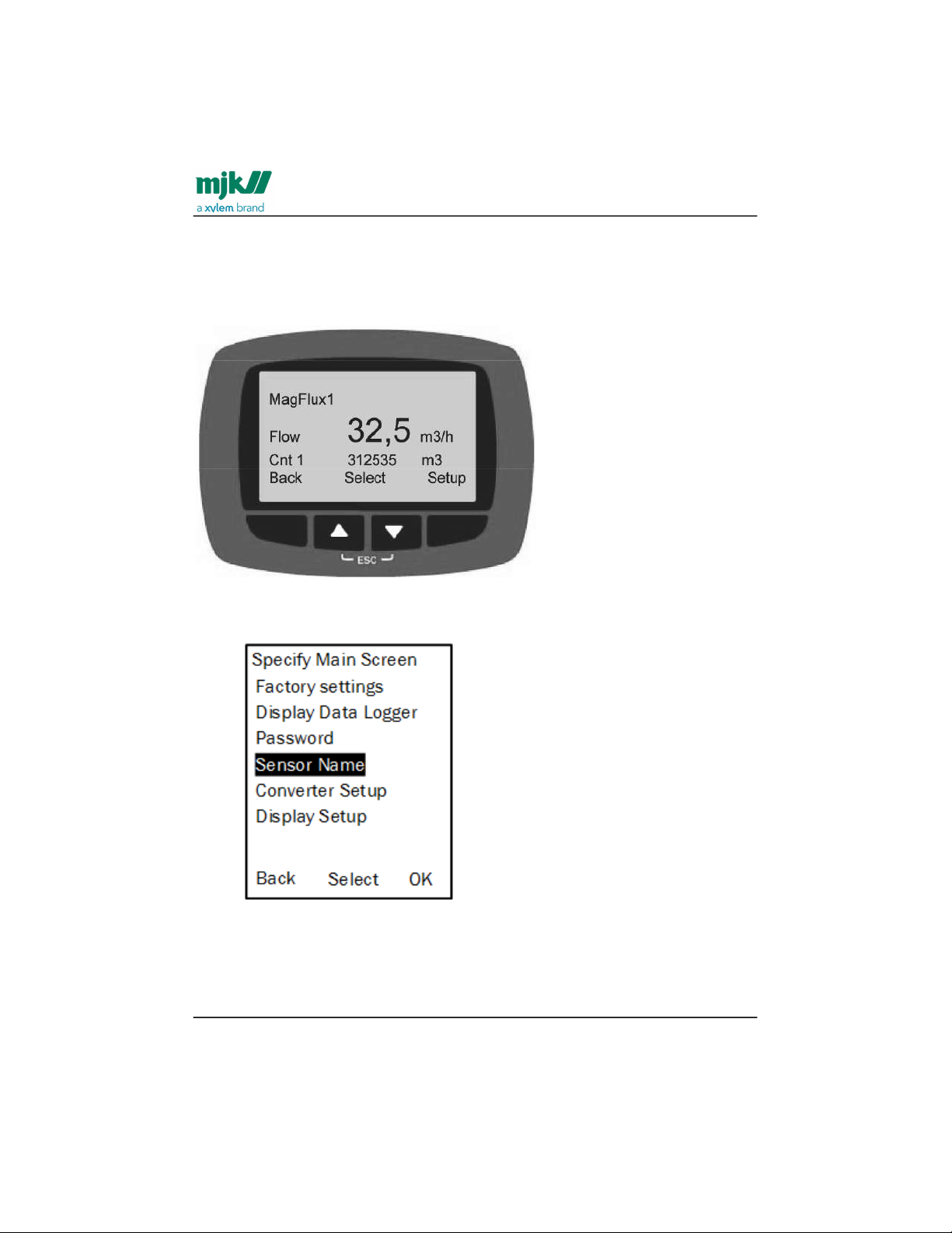
sensor (here: MagFlux1). It is consequently shown on the main display with up to four
display lines.
Press the up/down keys to highlight the required menu line (here: Sensor Name)
and press OK.
Find Quality Products Online at: [email protected]
www.GlobalTestSupply.com
Page 65
MagFlux® Series
EN 3.05 Version 2105
MagFlux® menus /Converter setup
65
2.
3.
4.
5.
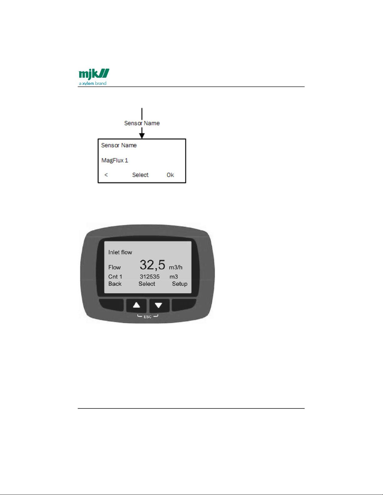
To change the default sensor name (MagFlux1), press the left/right keys to
highlight the wanted character.
Select the digits one by one with the left/right keys and set the value with the up/
down keys.
Continue until the name has been set to, for example, Inlet flow (see the
following).
Press OK.
The available characters depend on the chosen language. English, for example,
provides the following character set:
a b c d e f g h i j k l m n o p q r s t u v w x y z A B C D E F G H I J K L M N O P Q R S T
U V W X Y Z <space> 1 2 3 4 5 6 7 8 9 and 0.
Converter setup
Converter Setup provides configuration options for volumes, batches, units, etc. See
detailed descriptions in the following sections and in the overview sections at the end.
Find Quality Products Online at: [email protected]
www.GlobalTestSupply.com
Page 66
MagFlux® Series
EN 3.05 Version 2105
MagFlux® menus /Converter setup
66
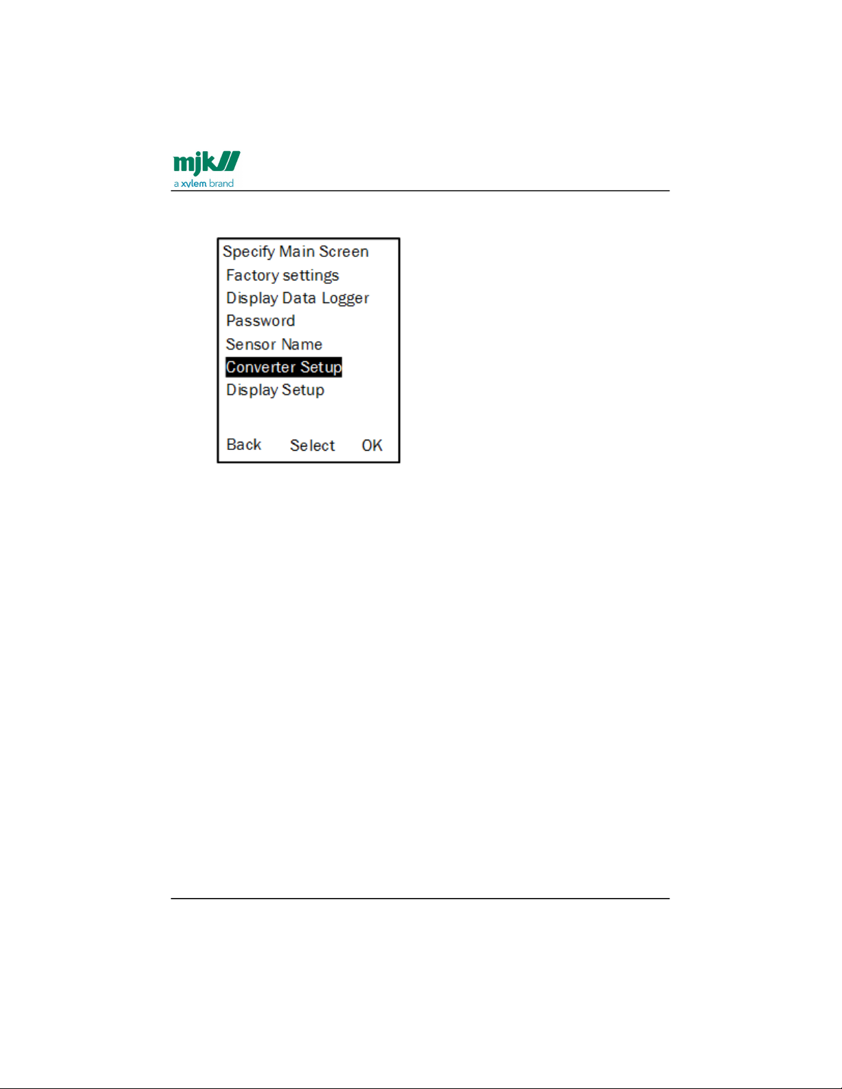
1. Press the up/down keys to highlight the required menu line (here: Converter
Setup) and press OK.
Find Quality Products Online at: [email protected]
www.GlobalTestSupply.com
Page 67
MagFlux® Series
EN 3.05 Version 2105
MagFlux® menus /Converter setup
67
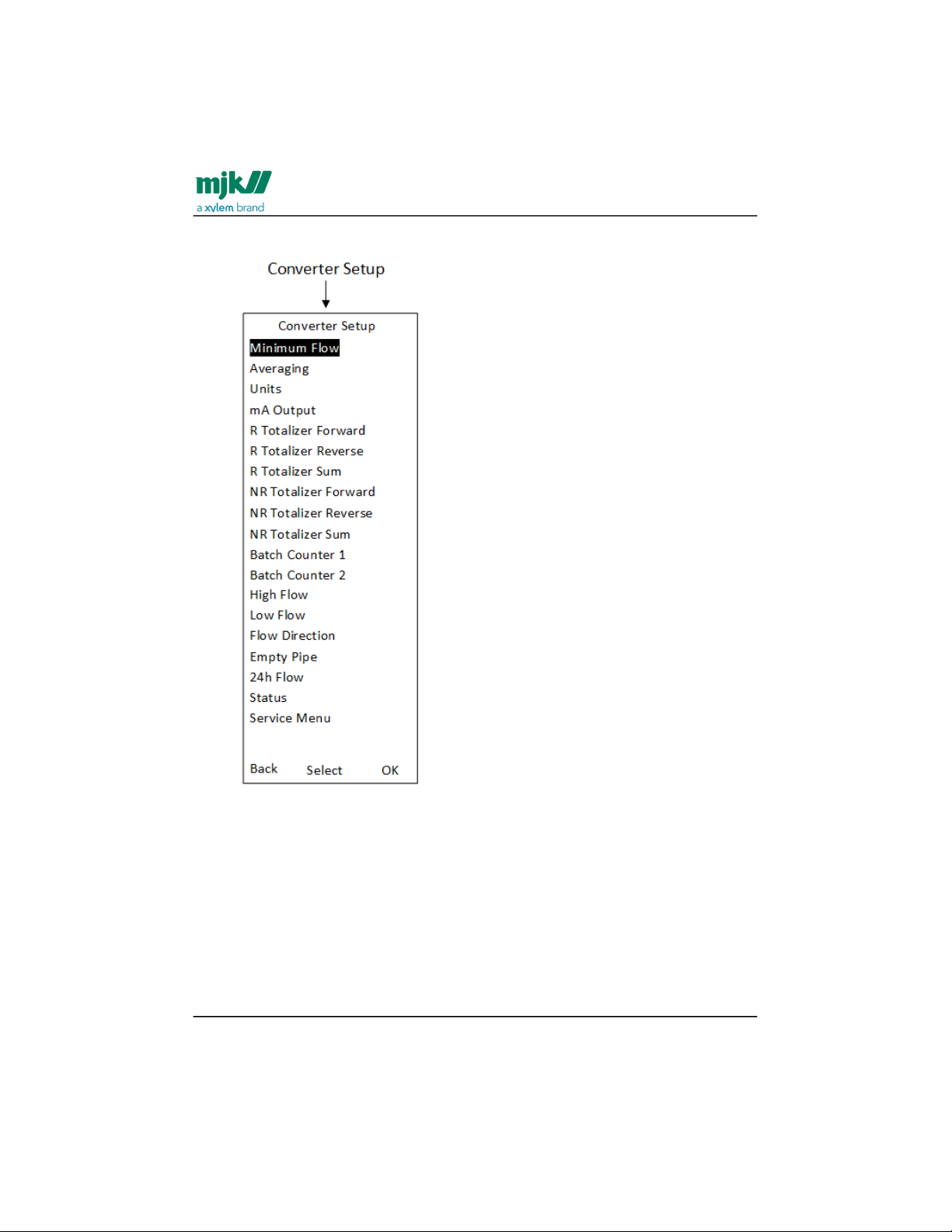
2. Press the up/down keys to highlight the required option and press OK.
The available options are described in detail in the following sections.
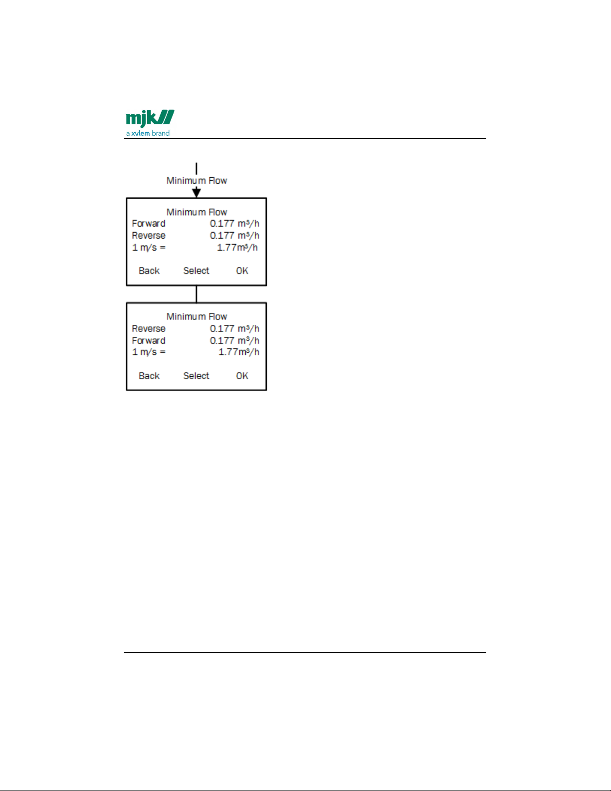
Minimum flow
Sets the minimum forward and reverse flow rate. MagFlux® flow meters are default set to
0,1 m/s. For other values, see Sizing Chart(see page20). The unit for the flow rate can be
set from the Units option (see Units(see page70)).
You can set both the forward and reverse minimum flow. By setting the minimum flow,
you indicate when the MagFlux® flow meter should stop measuring.
Find Quality Products Online at: [email protected]
www.GlobalTestSupply.com
Page 68
MagFlux® Series
EN 3.05 Version 2105
MagFlux® menus /Converter setup
68
1.
2.
3.
The 1 m/s indicates the flow volume at the selected unit.
Select the digits one by one with the left/right keys and set the value with the up/
down keys.
When you press OK, Reverse and Forward will change places and you can edit
the other one.
Press OK to save.
Find Quality Products Online at: [email protected]
www.GlobalTestSupply.com
Page 69
MagFlux® Series
EN 3.05 Version 2105
MagFlux® menus /Converter setup
69
1.
2.
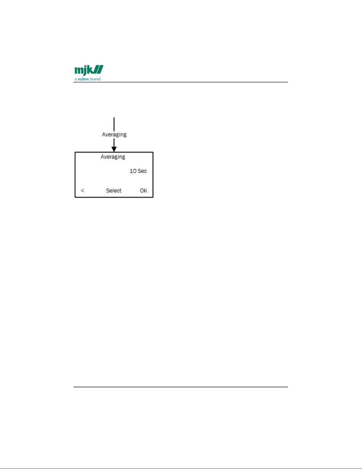
Averaging
Standard averaging (the first setting) indicates the time period within which
measurements are smoothed and averaged.
In Averaging, to change the standard averaging period, select the digits one by
one with the left/right keys and set the value with the up/down keys.
Press OK.
Find Quality Products Online at: [email protected]
www.GlobalTestSupply.com
Page 70
MagFlux® Series
EN 3.05 Version 2105
MagFlux® menus /Converter setup
70
1.
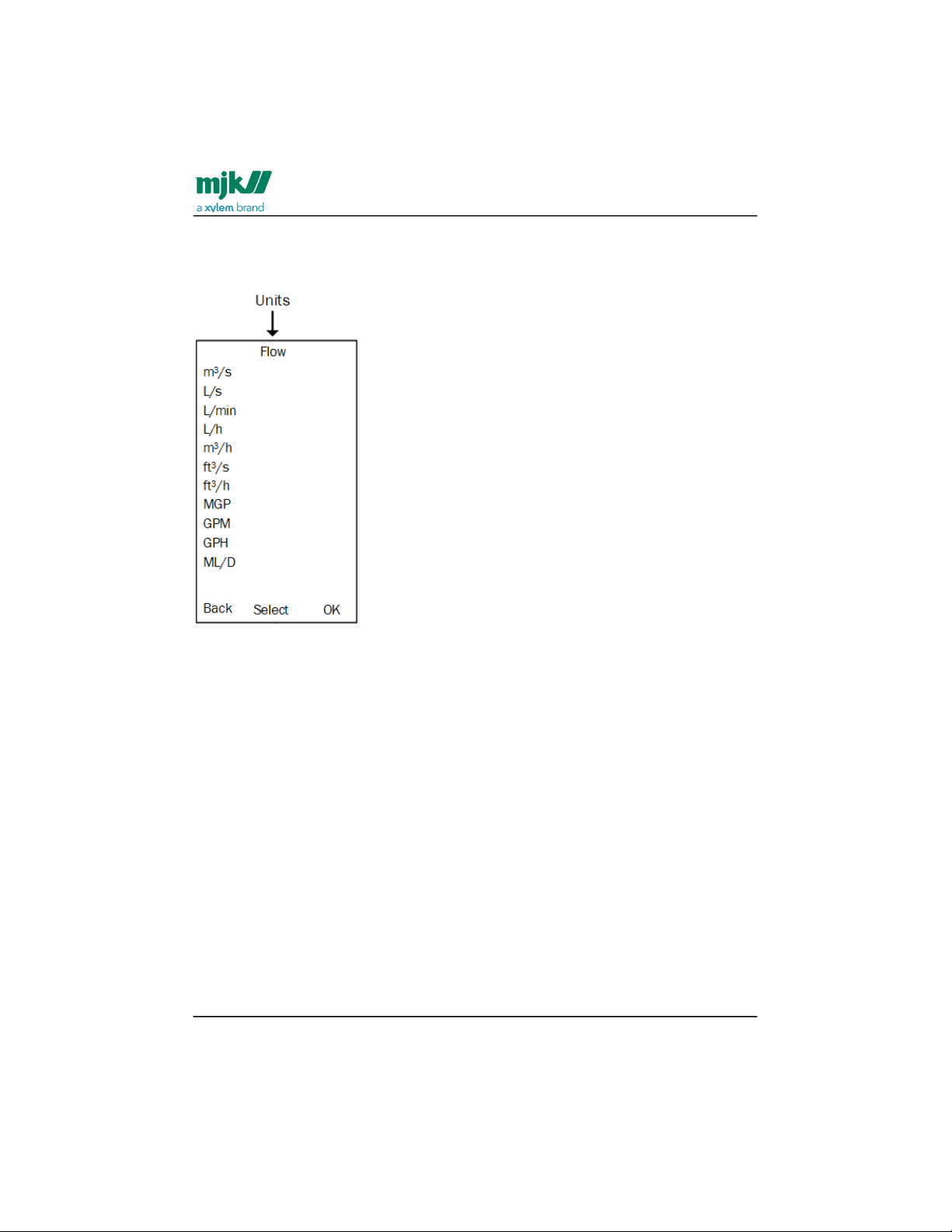
Units
Sets the unit for the flow rate. The available units are shown below.
Press the up/down keys to highlight the required unit and press OK.
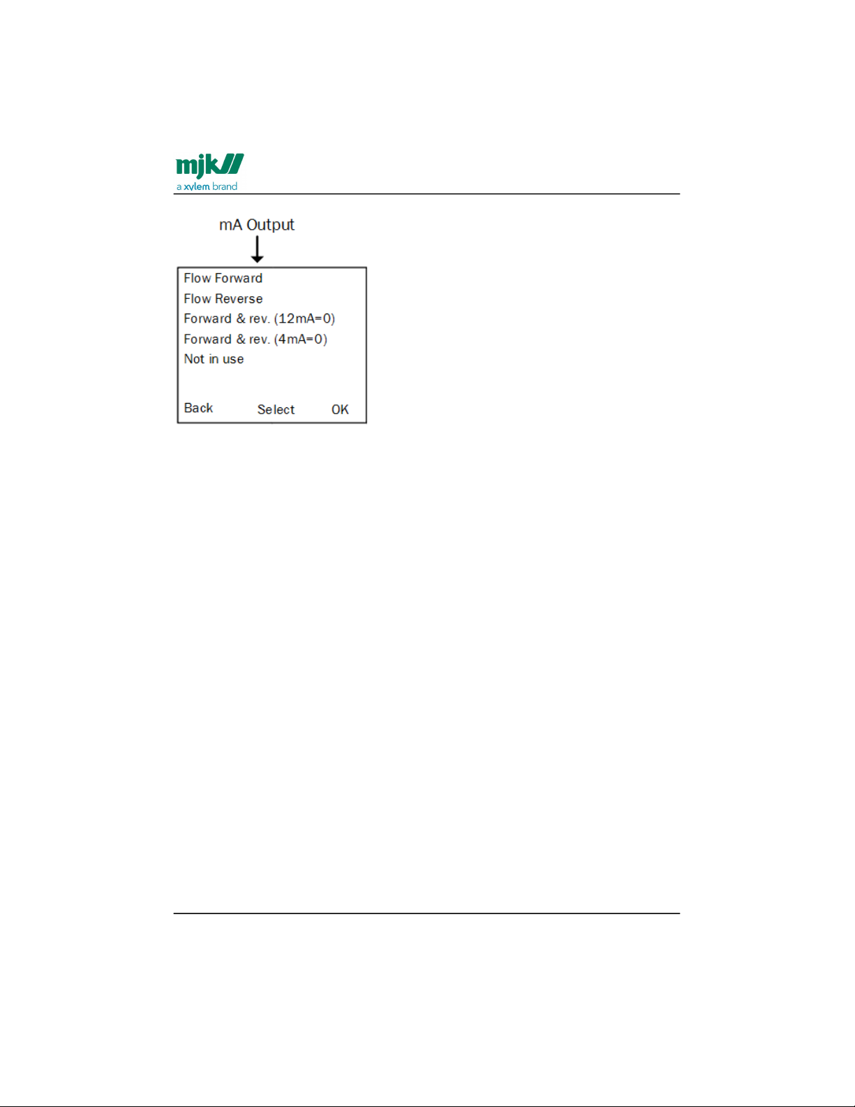
mA output
When a MagFlux® is connected to a power supply for the first time, the mA output is
automatically set to provide 4 mA at zero flow and 20 mA at a flow corresponding to the
theoretical Q
max
of the flow sensor. Changes in the mA setting will not affect the relay
output settings.
Note: Both values can be set in the range 10% to 120%, making it possible to increase
or decrease the mA signal.
The mA Output parameters can be configured in four different ways. Each option is
described in the following sections.
Find Quality Products Online at: [email protected]
www.GlobalTestSupply.com
Page 71
MagFlux® Series
EN 3.05 Version 2105
MagFlux® menus /Converter setup
71
•
•
•
Using the factory setup, MagFlux® returns to default mA settings corresponding to the
chosen MagFlux® flow sensors Q
min
and Q
max
. The mA output is an active output, and
the maximum load is 600 Ohm. The upper limit for the mA output is 20,5 mA:
3,75 mA indicates the mA output is not in use
3,5 mA indicates flow under 4 mA level
20,5 mA indicates flow higher than 20 mA level.
The 20 mA maximum output is rounded up to the nearest round figure.
Example: The maximum flow of 17.676 m3/h for a DN25 is rounded up to 20.000 m3/h.
Flow forward
The mA signal provides 4 mA at zero flow and 20 mA at Q
max
in the forward direction.
The 1 m/s indicates the flow volume at the selected unit.
Find Quality Products Online at: [email protected]
www.GlobalTestSupply.com
Page 72
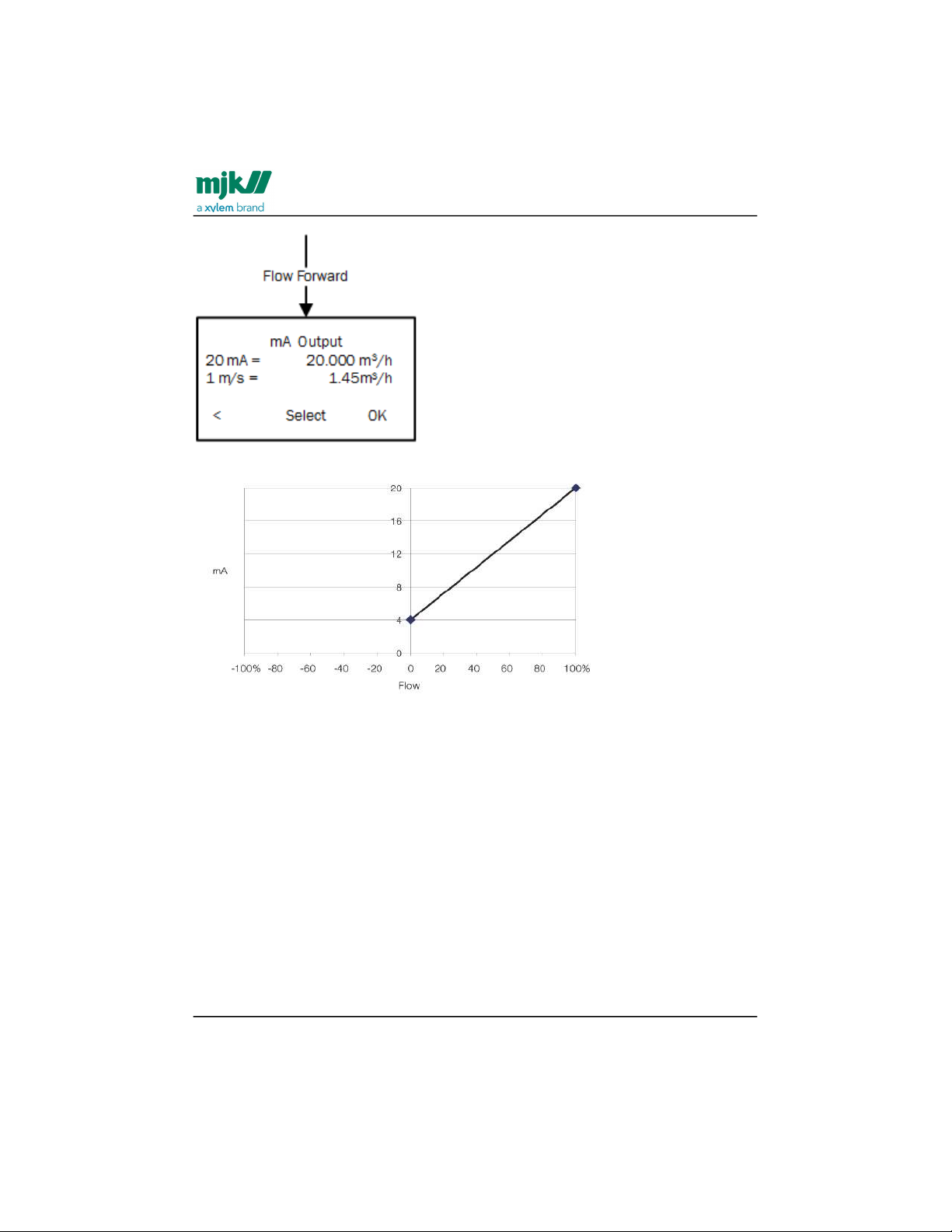
MagFlux® Series
EN 3.05 Version 2105
MagFlux® menus /Converter setup
72
Flow reverse
The mA signal provides 4 mA at zero flow and 20 mA at Q
max
in the reverse direction.
The 1 m/s indicates the flow volume at the selected unit.
Find Quality Products Online at: [email protected]
www.GlobalTestSupply.com
Page 73
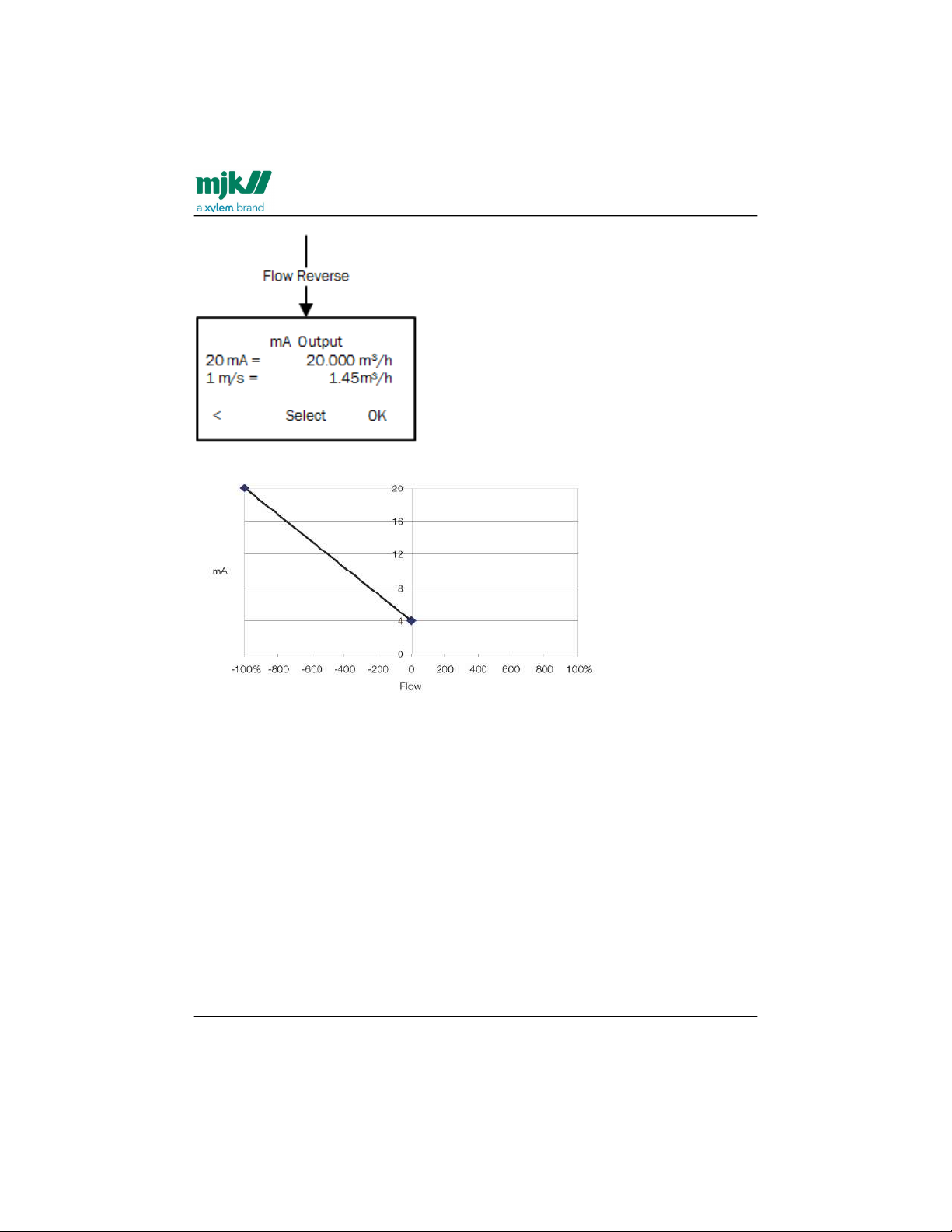
MagFlux® Series
EN 3.05 Version 2105
MagFlux® menus /Converter setup
73
Forward & rev. (12mA=0)
The mA signal provides 4 to 20 mA reverse to forward direction with 12 mA at zero flow.
The 1 m/s indicates the flow volume at the selected unit.
Find Quality Products Online at: [email protected]
www.GlobalTestSupply.com
Page 74
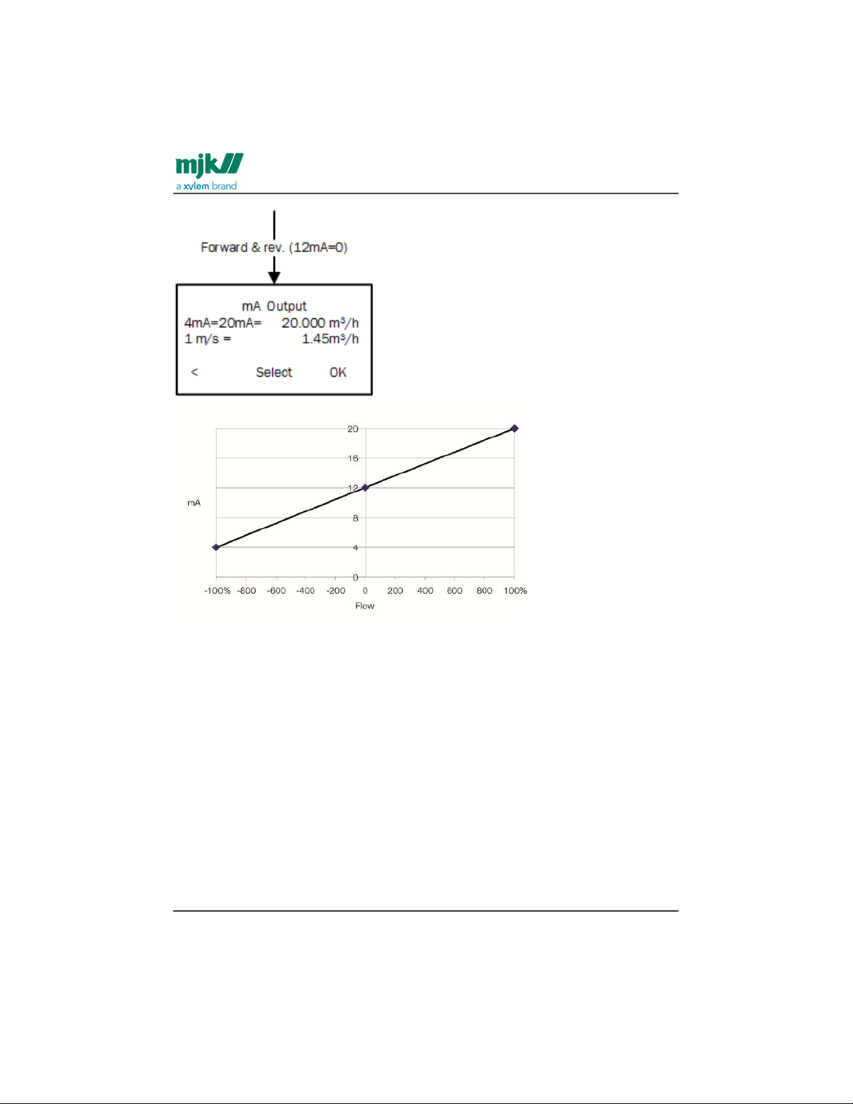
MagFlux® Series
EN 3.05 Version 2105
MagFlux® menus /Converter setup
74
Forward & rev. (4mA=0)
The mA signal provides 4 to 20 mA for forward and reverse flow with 4 mA at zero flow.
The 1 m/s indicates the flow volume at the selected unit.
Find Quality Products Online at: [email protected]
www.GlobalTestSupply.com
Page 75
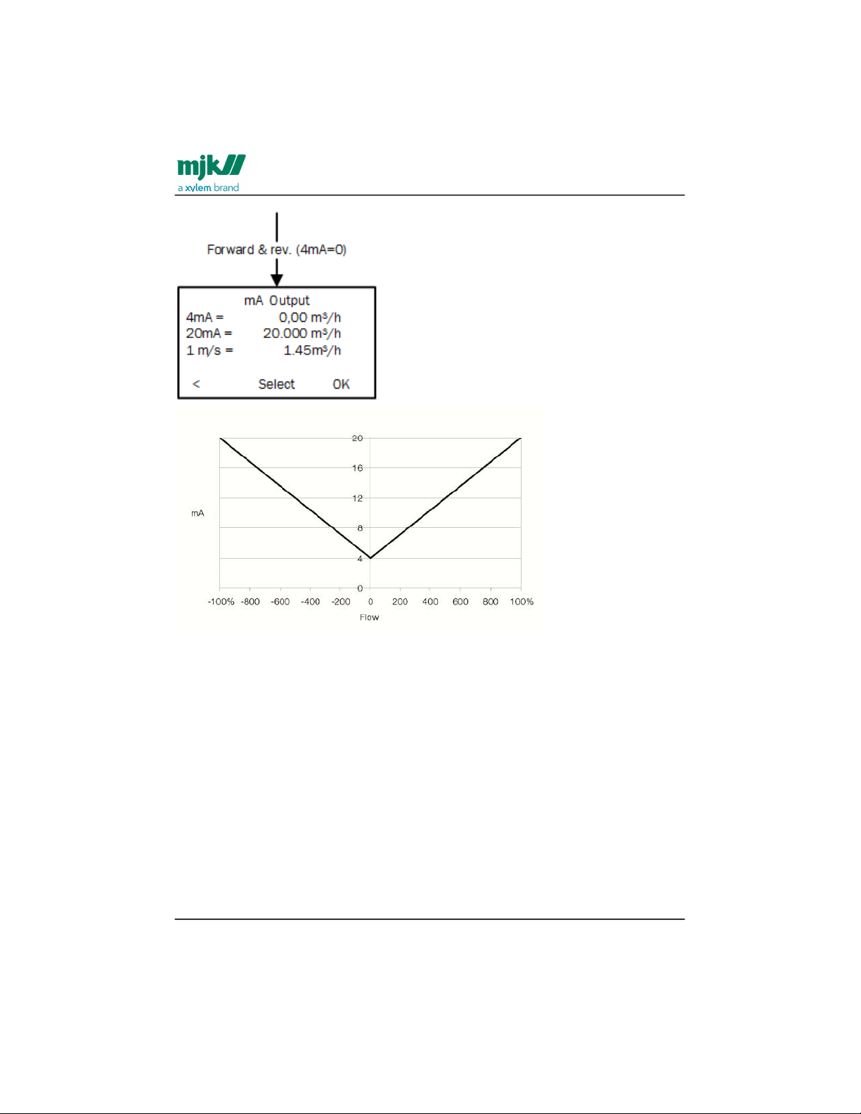
MagFlux® Series
EN 3.05 Version 2105
MagFlux® menus /Converter setup
75
•
•
•
Not in use
The mA Output option is not being used.
The 1 m/s indicates the flow volume at the selected unit.
MJK totalizers
The MagFlux® provides six totalizers, each with two or three output options. Up to two
totalizers can be assigned to one digital output.
The totalizers are:
Resettable Totalizer Forward
Resettable Totalizer Reverse
Resettable Totalizer Sum
and
Find Quality Products Online at: [email protected]
www.GlobalTestSupply.com
Page 76

MagFlux® Series
EN 3.05 Version 2105
MagFlux® menus /Converter setup
76
•
•
•
•
•
•
•
•
•
•
•
Non-Resettable Totalizer Forward
Non-Resettable Totalizer Reverse
Non-Resettable Totalizer Sum
The available output options for the resettable totalizers are:
Mechanical Relay (DO2)
Opto Relay (DO1) (light-triggered electronic relay)
Display only (on the display unit)
The available output option for the non-resettable totalizers is:
Display only (on the display unit)
If a chosen output is not available (dedicated to another function), a Device Exception
pop-up message will inform the operator.
Settings and limits for resettable totalizers
Totalizer Forward Unit: Available units are l, hl, kl, m3, ft3, gal and MG.
Reset with Digital Input: Reset the totalizer via the digital input (DI).
On-time: The pulse length of the opto digital output (DO1) is adjustable from 1
ms to 10 secs. The pulse length of the mechanical digital relay (DO2) is
adjustable from 100 ms to 10 secs.
Volume between Pulses: Select a volume between pulses in steps of: 0,001,
0,01, 0,1, 1, 10, 100 and 1000.
Find Quality Products Online at: [email protected]
www.GlobalTestSupply.com
Page 77
MagFlux® Series
EN 3.05 Version 2105
MagFlux® menus /Converter setup
77
MagFlux® Totalizer Output Setting
Metric
Optical DO
1 @100
mSec.
Mechanical
DO 2 @100
mSec.
DN [mm] min. max. min. max. Unit
15 0,001 1 0,1 1
m
3
20 0,001 1 0,1 1
m
3
25 0,01 10 1 10
m
3
32 0,01 10 1 10
m
3
40 0,01 10 1 10
m
3
50 0,01 10 1 10
m
3
65 0,01 100 1 100
m
3
80 0,1 100 10 100
m
3
100 0,1 100 10 100
m
3
125 0,1 100 10 100
m
3
150 0,1 100 10 100
m
3
200 0,1 1000 10 1000
m
3
250 1 1000 100 1000
m
3
300 1 1000 100 1000
m
3
350 1 1000 100 1000
m
3
400 1 1000 100 1000
m
3
Find Quality Products Online at: [email protected]
www.GlobalTestSupply.com
Page 78
MagFlux® Series
EN 3.05 Version 2105
MagFlux® menus /Converter setup
78
MagFlux® Totalizer Output Setting
Metric
Optical DO
1 @100
mSec.
Mechanical
DO 2 @100
mSec.
DN [mm] min. max. min. max. Unit
450 1 1000 100 1000
m
3
500 1 1000 100 1000
m
3
600 1 10000 100 10000
m
3
700 1 10000 1000 10000
m
3
800 10 10000 1000 10000
m
3
900 10 10000 1000 10000
m
3
1000 10 10000 1000 10000
m
3
1200 10 10000 1000 10000
m
3
If a required volume between pulses is not contained in the above steps, for example,
for a preset to a sampler, use the batch counter option. The relays are limited to a
minimum and a maximum of pulses per hour depending on the 20 mA scale and the ontime of the relay in milliseconds.
DO 1 (Opto Relay): The maximum limit is 500 pulses per sec at 1 ms pulse length.
The formula for the minimum flow unit per pulses is:(flow at 20mA) x (pulse delay in
mSec) / 1800000
Example: Min. flow unit/pulses for DN 100 max. flow 300 m3/h ?
Minimum flow unit per pulses = 300 m3 x 100 mSec / 1800000 = 0,016 m3 which is
rounded to 0,1 m3 by the MagFlux®
The formula for the maximum flow unit per pulses is:(flow at 20mA)
Example: DN 100 max. flow 300 m3/h ?
Maximum flow unit per pulses = 300 m
3
Find Quality Products Online at: [email protected]
www.GlobalTestSupply.com
Page 79

MagFlux® Series
EN 3.05 Version 2105
MagFlux® menus /Converter setup
79
DO 2 (Mechanical Relay): The maximum limit is 120 pulses per hour.
The formula for minimum flow unit per pulses is:(flow at 20mA) / 120
Example: DN 100 max. flow 300 m3/h ?
Minimum flow unit per pulses = 300 / 120 = 2,5 m3 which is rounded to 10 m3 by
MagFlux®
The formula for maximum flow unit per pulses is:(flow at 20mA)
Example: DN 100 max. flow 300 m3/h ?
Maximum flow unit per pulses = 300 m
3
Resettable totalizers
Totalizers can be reset from the main menu(see page53)and via thedigital input(see
page37)DI.
Find Quality Products Online at: [email protected]
www.GlobalTestSupply.com
Page 80
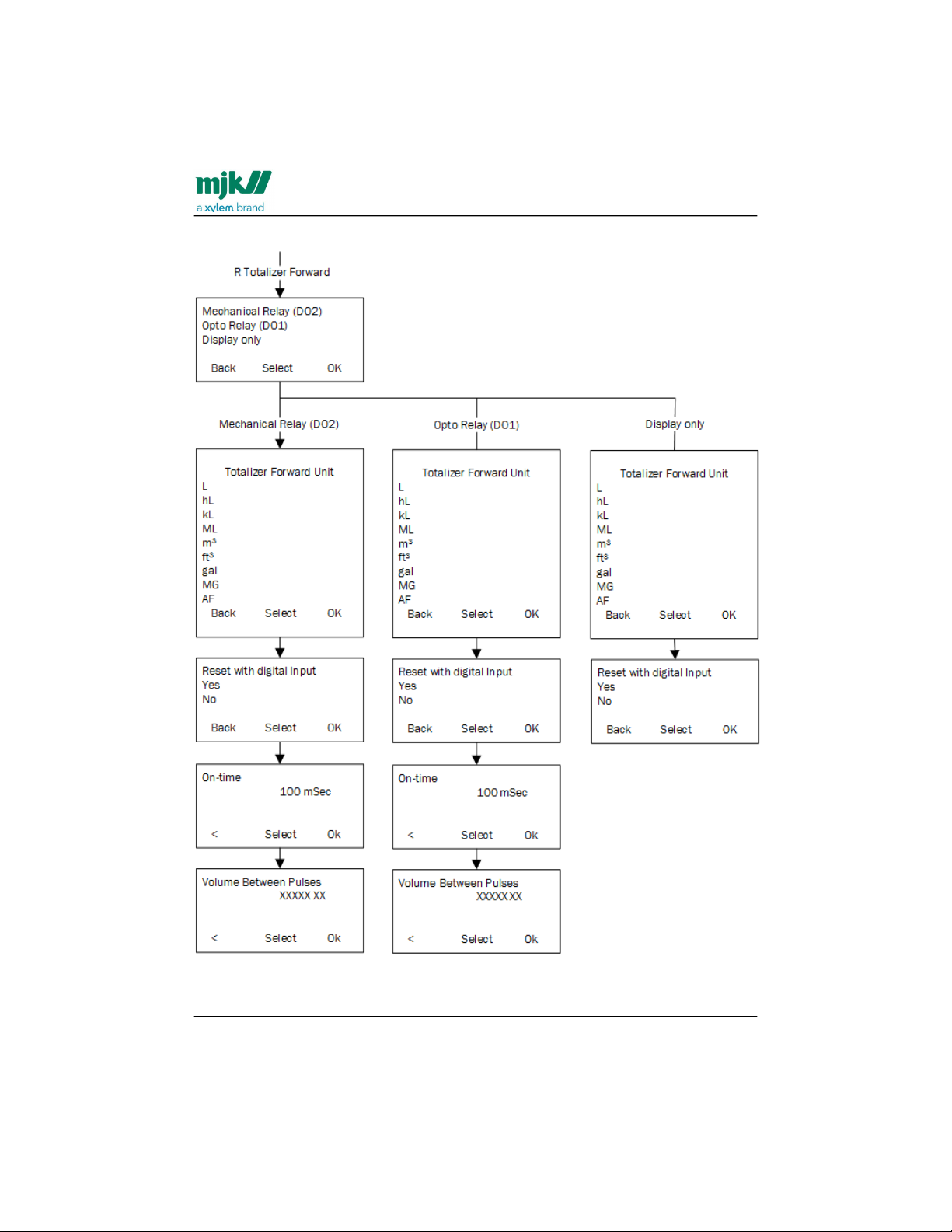
MagFlux® Series
EN 3.05 Version 2105
MagFlux® menus /Converter setup
80
Find Quality Products Online at: [email protected]
www.GlobalTestSupply.com
Page 81
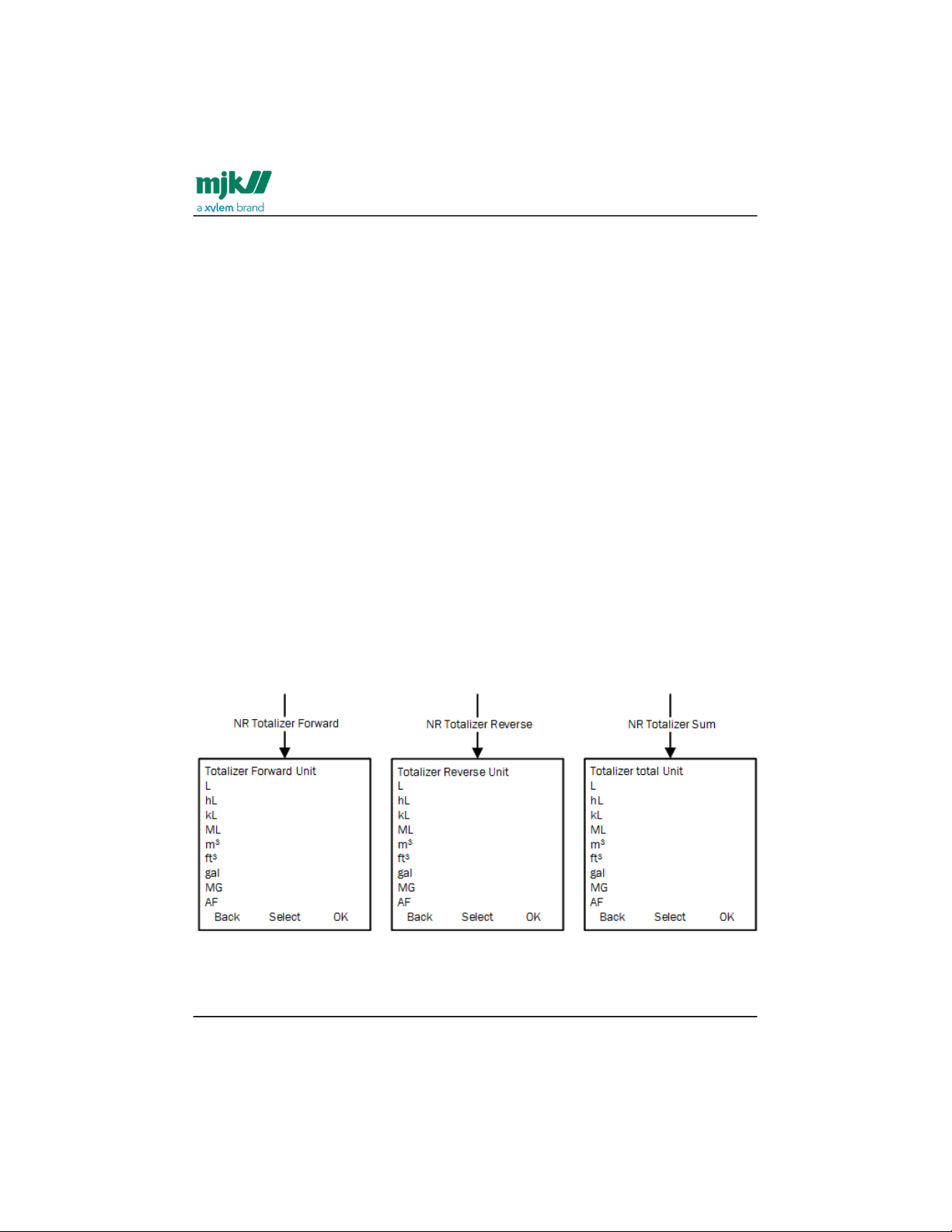
MagFlux® Series
EN 3.05 Version 2105
MagFlux® menus /Converter setup
81
Resettable forward totalizer
RFTot:The Totalizer counts the forward flow volume according to the primary flow
direction selected at startup. The Totalizer counts in selected units and is resettable. The
counter can be connected to the relays or to the display only. To reset the counter, the
totalizer must be present in the main display and be selected by the up/down keys
followed by a click on Reset. Alternatively, it can be reset via thedigital input(see page37)
DI.
Resettable reverse totalizer
RRTot: The Totalizer counts the reverse flow volume according to the primary flow
direction selected at startup. The Totalizer counts in selected units and is resettable. The
counter can be connected to the relays or to the display only. To reset the counter, the
totalizer must be present in the main display and be selected by the up/down keys
followed by a click on Reset. Alternatively it can be reset via thedigital input(see page37)
DI.
Resettable Sum Totalizer
RSTot: The Totalizer counts the sum of forward flow volume minus the reverse flow
volume according to the primary flow direction selected at startup. The Totalizer counts
in selected units and is resettable. The counter can be connected to the relays or to the
display only. To reset the counter, the totalizer must be present in the Main display and
be selected by the up/down keys followed by a click on Reset. Alternatively it can be
reset via the digital input(see page37)t DI.
Non-resettable totalizers
Find Quality Products Online at: [email protected]
www.GlobalTestSupply.com
Page 82

MagFlux® Series
EN 3.05 Version 2105
MagFlux® menus /Converter setup
82
NR totalizer forward
NR FTot: The Totalizer counts the forward flow volume according to the primary flow
direction selected at start up. The Totalizer counts in selected units and cannot be reset.
The counter can only be selected from the Main display.
NR totalizer reverse
NR RTot: The Totalizer counts the reverse flow volume according to the primary flow
direction selected at start up. The Totalizer counts in selected units and cannot be reset.
The counter can only be selected from the Main display.
NR totalizer sum
NR Cnt: The Totalizer counts the sum of forward flow volume minus the reverse flow
volume according to the primary flow direction selected at startup. The Totalizer counts
in selected units and cannot be reset. The counter can only be selected from the Main
display.
MJK batch counters 1 & 2
The batch counters can operate in three different ways: automatically, manually or
adaptively, and they deduct a reverse flow from the forward flow.
Find Quality Products Online at: [email protected]
www.GlobalTestSupply.com
Page 83
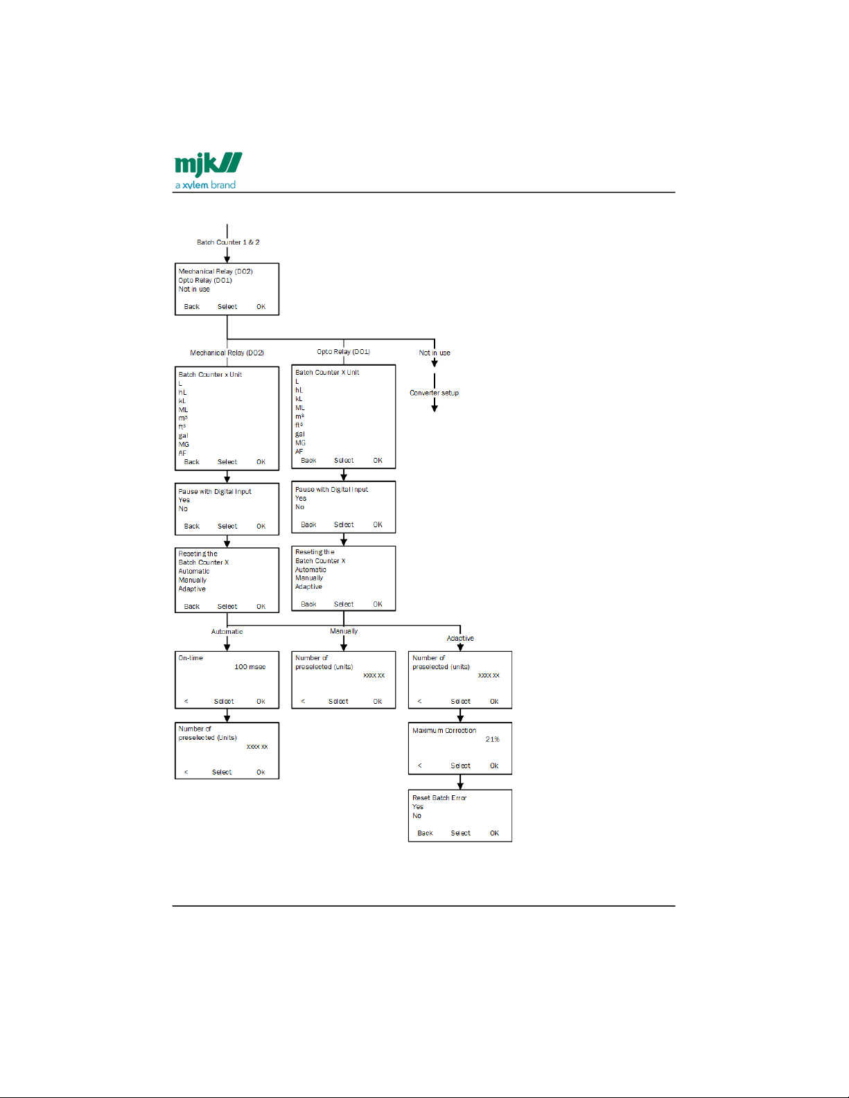
MagFlux® Series
EN 3.05 Version 2105
MagFlux® menus /Converter setup
83
Find Quality Products Online at: [email protected]
www.GlobalTestSupply.com
Page 84
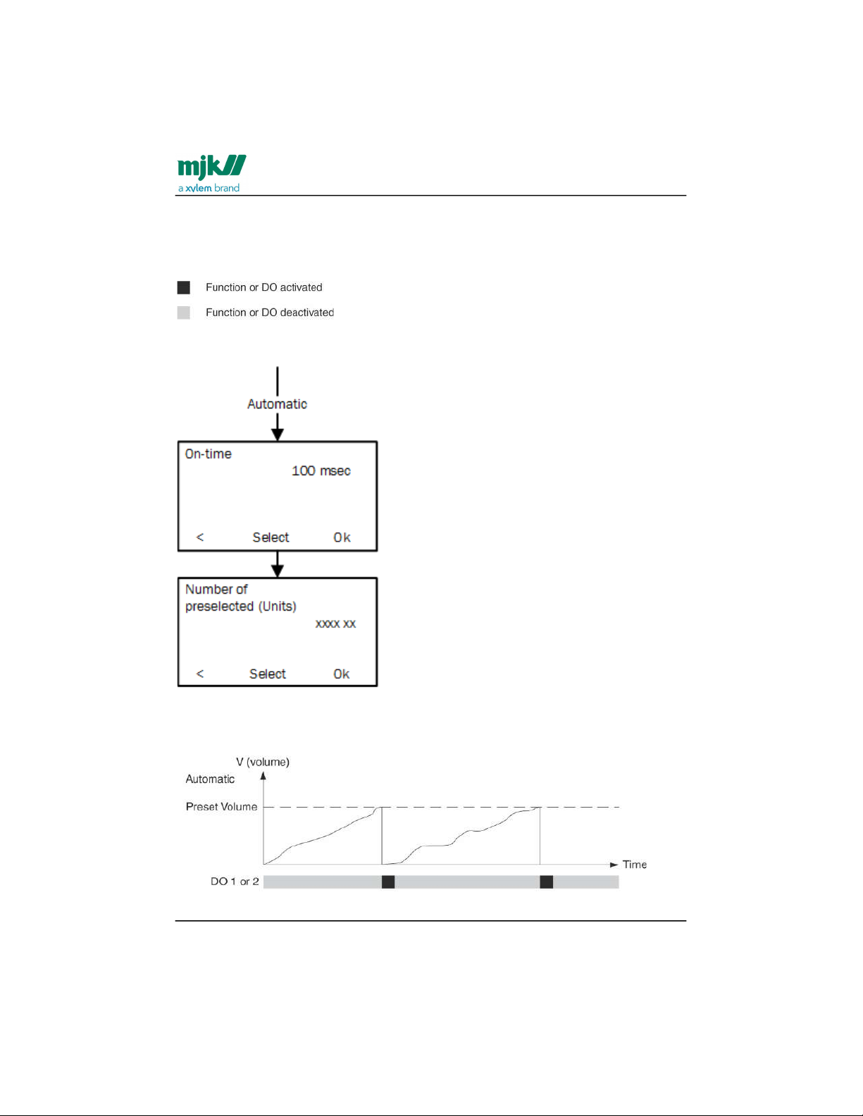
MagFlux® Series
EN 3.05 Version 2105
MagFlux® menus /Converter setup
84
In the following descriptions of the batch counters, the function or digital status is
illustrated as follows:
Automatic Batch Counter: The automatic batch counter issues a signal, when a preset
volume is reached.
On-time: The period of time in which the relay is activated (drawn).
Number of preselected (units): The preset batch volume.
Find Quality Products Online at: [email protected]
www.GlobalTestSupply.com
Page 85
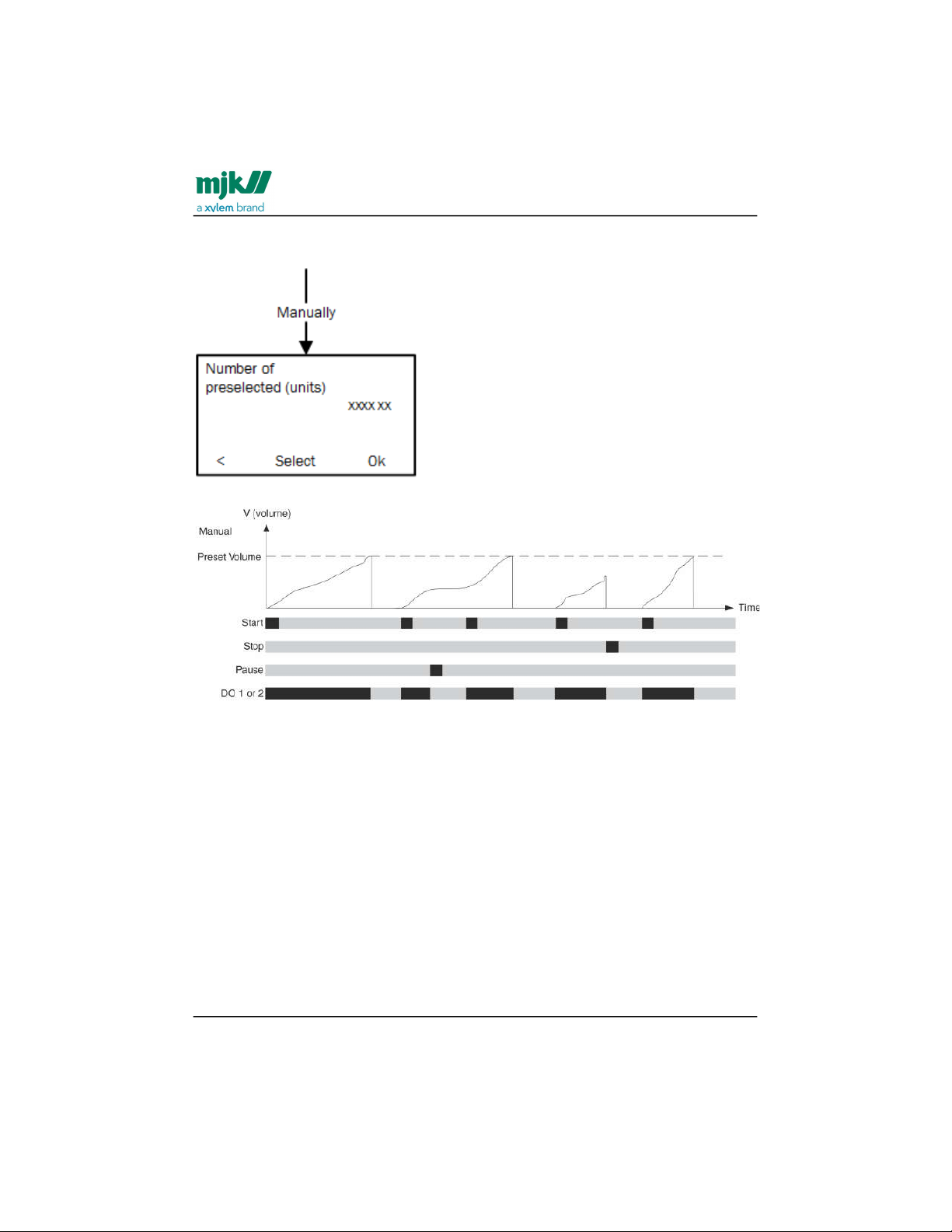
MagFlux® Series
EN 3.05 Version 2105
MagFlux® menus /Converter setup
85
Manual Batch Counter: The counter issues signals as determined by manual start, stop
and pause commands. A manual stop is equivalent to a reset command.
Number of preselected (units): The preset batch volume.
Find Quality Products Online at: [email protected]
www.GlobalTestSupply.com
Page 86
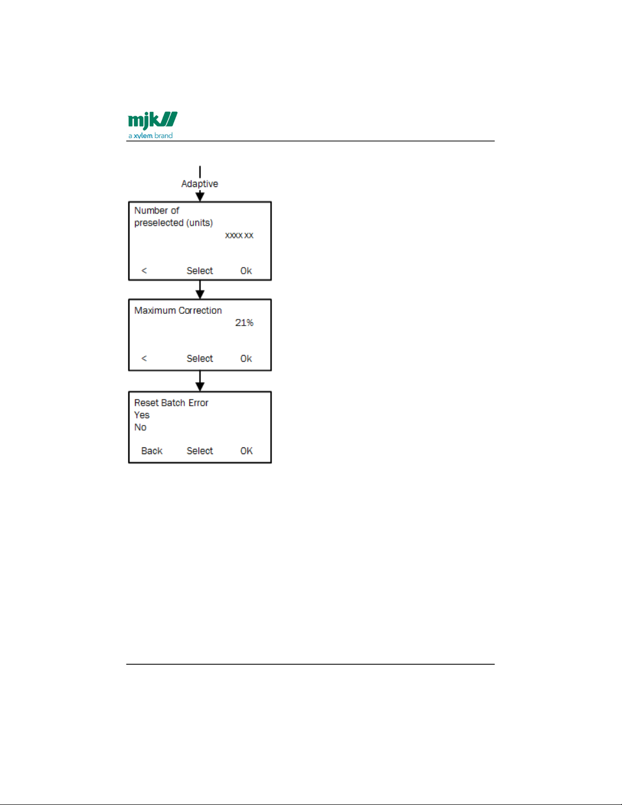
MagFlux® Series
EN 3.05 Version 2105
MagFlux® menus /Converter setup
86
Adaptive Batch Counter: The counter compensates for overrun and insufficient flow.
Number of preselected (units): The preset batch volume.
Maximum Correction: The correction in percent that triggers an error message or an
alarm.
Reset Batch Error: Reset the batch correction percentage to 0%.
Find Quality Products Online at: [email protected]
www.GlobalTestSupply.com
Page 87
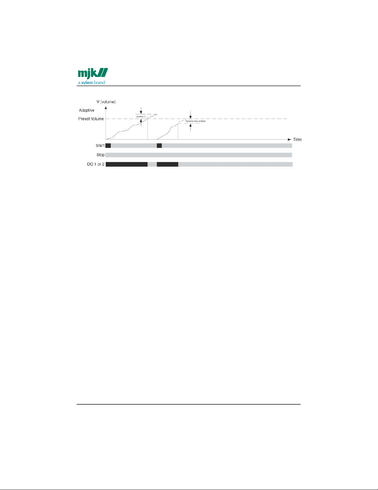
MagFlux® Series
EN 3.05 Version 2105
MagFlux® menus /Converter setup
87
•
•
•
•
Settings and limits for batch counters
Batch counter units: Available units are l, hl, kl, m3, ft3, gal and MG.
Start, stop or pause with Digital Input: The manual and the adaptive batch
counters can be started, stopped or paused via the digital input (DI)
On-time: The pulse length of the opto digital output (DO1) is adjustable from 1
ms to 10 secs. The pulse length of the mechanical digital relay (DO2) is
adjustable from 100 ms to 10 secs.
Volume between pulses: Select a volume between pulses as listed in the table
overleaf. The relays are limited to a minimum and a maximum of pulses pr. hour
depending on the 20 mA scale and the on-time of the relay in milliseconds.
Find Quality Products Online at: [email protected]
www.GlobalTestSupply.com
Page 88
MagFlux® Series
EN 3.05 Version 2105
MagFlux® menus /Converter setup
88
MagFlux® Batch Counter Output Settings - Metric
Optical DO1 @100 mSec. Mechanical DO2 @100 mSec.
DN
[mm]
min. max. min. max. Unit
Automatic
Manually/
adaptive
Automatic
Manually/
adaptive
15 0,0002778 0,0138889 5
0,041666
7
0,0138889 5
m
3
20 0,0005556 0,0277778 10
0,083333
3
0,0277778 10
m
3
25 0,001111 0,055556 20 0,166667 0,055556 20
m
3
32 0,001667 0,083333 30 0,250000 0,083333 30
m
3
40 0,002778 0,138889 50 0,416667 0,138889 50
m
3
50 0,004167 0,208333 75 0,625000 0,208333 75
m
3
65 0,005556 0,277778 100 0,833333 0,277778 100
m
3
80 0,011111 0,555556 200 1,666667 0,555556 200
m
3
100 0,016667 0,833333 300 2,500000 0,833333 300
m
3
125 0,022222 1,111111 400 3,333333 1,111111 400
m
3
150 0,033333 1,666667 600 5,000000 1,666667 600
m
3
200 0,055556 2,777778 1000 8,333333 2,777778 1000
m
3
250 0,111111 5,555556 2000 16,66667 5,555556 2000
m
3
300 0,138889 6,944444 2500 20,83333 6,944444 2500
m
3
350 0,166667 8,333333 3000 25,00000 8,333333 3000
m
3
400 0,250000 12,500000 4500 37,50000 12,500000 4500
m
3
Find Quality Products Online at: [email protected]
www.GlobalTestSupply.com
Page 89
MagFlux® Series
EN 3.05 Version 2105
MagFlux® menus /Converter setup
89
MagFlux® Batch Counter Output Settings - Metric
Optical DO1 @100 mSec. Mechanical DO2 @100 mSec.
DN
[mm]
min. max. min. max. Unit
Automatic
Manually/
adaptive
Automatic
Manually/
adaptive
450 0,333333 16,666667 6000 50,00000 16,666667 6000
m
3
500 0,388889 19,444444 7000 58,33333 19,444444 7000
m
3
600 0,555556 27,777778 10000 83,33333 27,777778 10000
m
3
700 0,833333 41,666667 15000 125,0000 41,666667 15000
m
3
800 1,111111 55,555556 20000 166,6667 55,555556 20000
m
3
900 1,388889 69,444444 25000 208,3333 69,444444 25000
m
3
1000 1,666667 83,333333 30000 250,0000 83,333333 30000
m
3
1200 2,222222 111,111111 40000 333,3333 111,111111 40000
m
3
Limitation of the automatic batch counter on DO1 (Opto Relay):The maximum limit
is 500 pulses per sec at 1 ms pulse length.
The formula for the minimum flow unit per pulses is:(flow at 20mA) x (pulse delay in
mSec) / 1800000
Example: Min. flow unit/pulses for DN 100 max. flow 300 m3/h ?
Minimum flow unit per pulses = 300 m3 x 100 mSec / 1800000 =0,016 m3 which is
rounded to 0,1 m3 by MagFlux®.
The formula for the maximum flow unit per pulses is:(flow at 20mA)
Example: DN 100 max. flow 300 m3/h ?
Maximum flow unit per pulses = 300 m
3
Limitation of the automatic batch counter on DO2 (mech. relay): The maximum limit
is 120 pulses per hour.
Find Quality Products Online at: [email protected]
www.GlobalTestSupply.com
Page 90

MagFlux® Series
EN 3.05 Version 2105
MagFlux® menus /Converter setup
90
The formula for minimum flow unit per pulses is:(flow at 20mA) / 120
Example: DN 100 max. flow 300 m3/h ?
Minimum flow unit per pulses = 300 / 120 = 2,5 m
3
The formula for maximum flow unit per pulses is:(flow at 20mA)
Example: DN 100 max. flow 300 m3/h ?
Maximum flow unit per pulses = 300 m
3
Limitation of the manual and adaptive batch counter on DO1 or DO2:
The formula for minimum flow unit per pulses is:(flow at 20mA) / 360
Example: DN 100 max. flow 300 m3/h ?
Minimum flow unit per pulses = 300 / 360 = 0,833 m
3
The formula for maximum flow unit per pulses is:(flow at 20mA)
Example: DN 100 max. flow 300 m3/h ?
Maximum flow unit per pulses = 300 m
3
High flow/low flow
Provides alarms and triggers relays when certain volume limits are exceeded or not
reached.
Find Quality Products Online at: [email protected]
www.GlobalTestSupply.com
Page 91
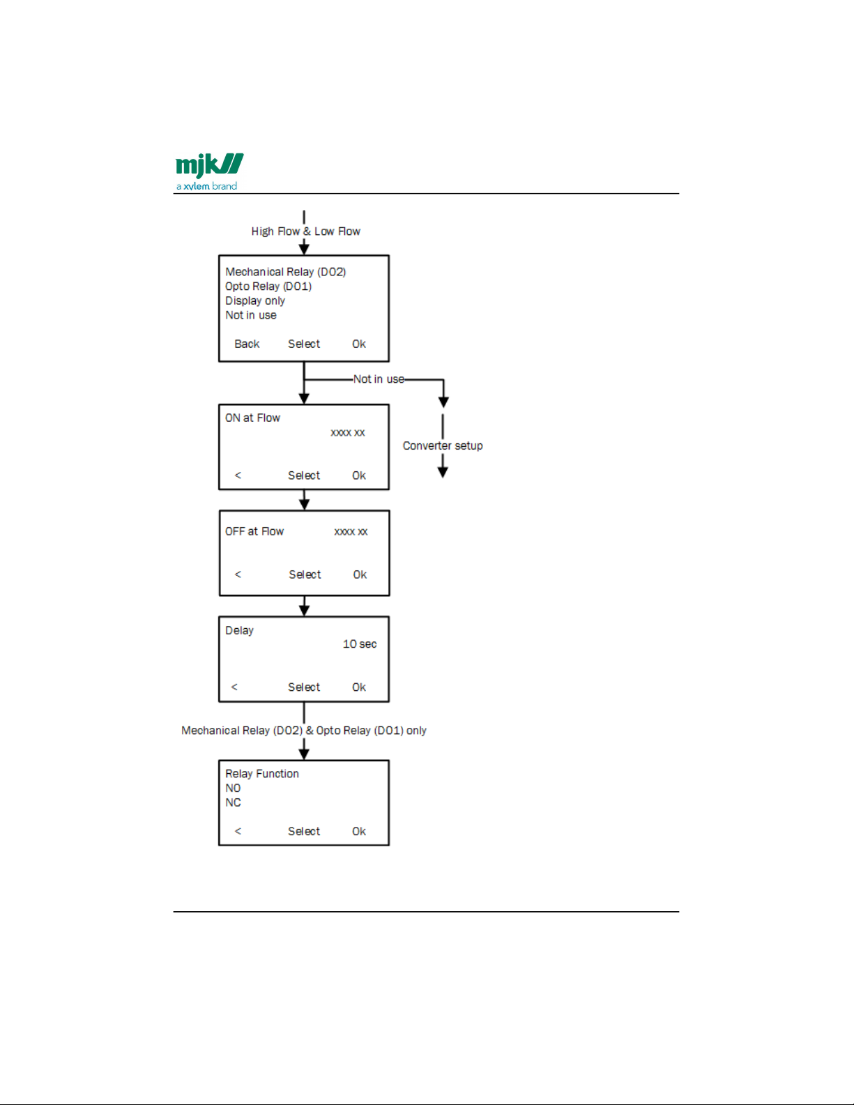
MagFlux® Series
EN 3.05 Version 2105
MagFlux® menus /Converter setup
91
The available output options for High Flow and Low Flow are:
Find Quality Products Online at: [email protected]
www.GlobalTestSupply.com
Page 92

MagFlux® Series
EN 3.05 Version 2105
MagFlux® menus /Converter setup
92
•
•
•
•
•
•
Mechanical Relay (DO2)
Opto Relay (DO1) (light-triggered, electronic relay)
Display only (signals to the display unit only)
Not in use (the High/Low Flow option is not being used)
ON at Flow: Issues an alarm and/or sends a signal when, for example, a high flow limit is
exceeded.
OFF at Flow: Cancels an alarm and/or sends a signal when recovering from, for
example, an overflow situation.
Delay: A delay in seconds can be set to compensate for positive and negative spikes in
the flow. The length is the time between an incident and setting an alarm.
Relay Function:
NO (Normally Open) determines the relay state under normal conditions.
NC (Normally Closed) determines the relay state under normal conditions.
Flow direction
Indicates the direction of the flow and determines the open/closed state of the relay.
The default Flow Direction is set to Direction A.
Find Quality Products Online at: [email protected]
www.GlobalTestSupply.com
Page 93
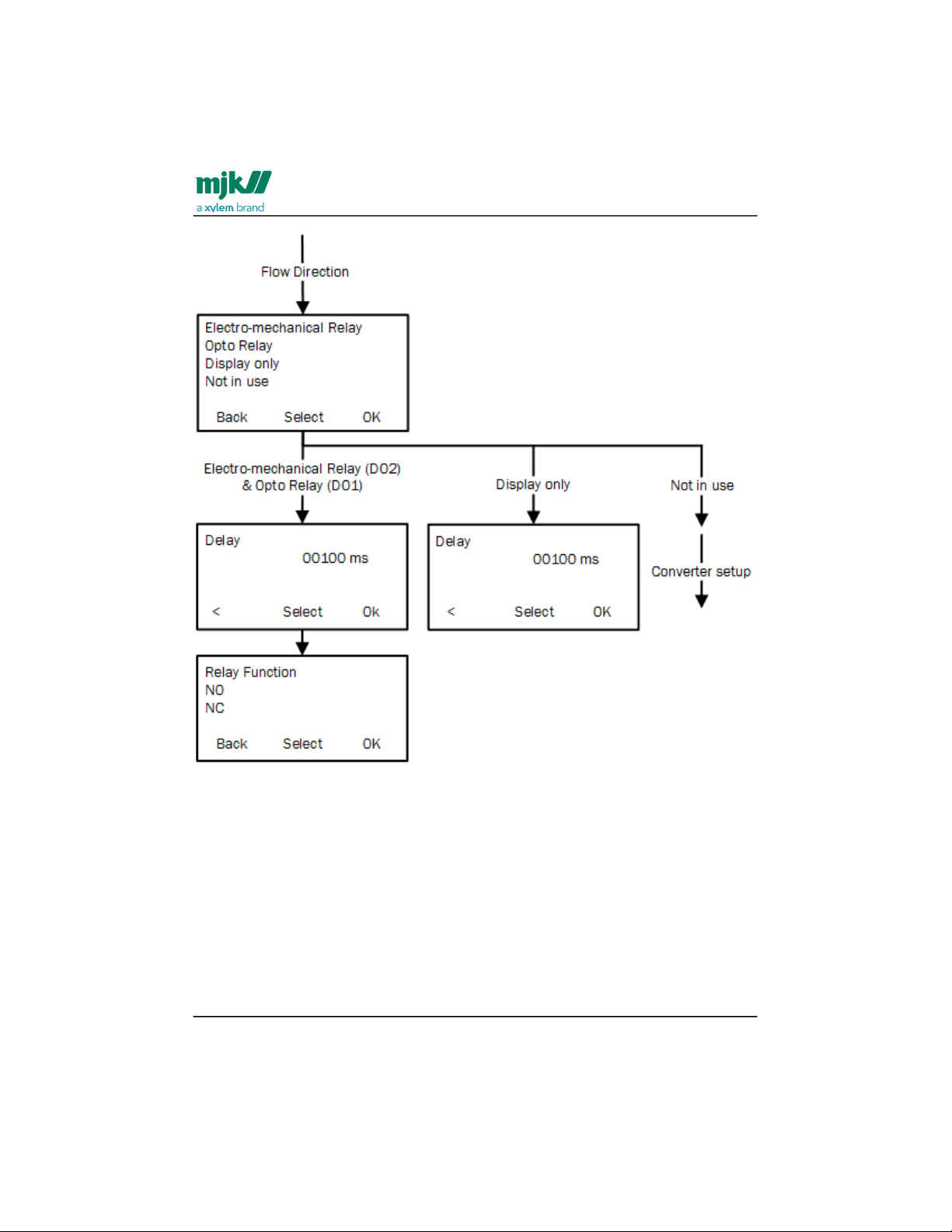
MagFlux® Series
EN 3.05 Version 2105
MagFlux® menus /Converter setup
93
•
•
•
•
•
•
The available output options for Flow Direction are:
Mechanical Relay (DO2)
Opto Relay (DO1) (light-triggered electronic relay)
Display only (signals to the display unit only)
Not in use (the Flow Direction option is not being used)
Delay: A delay in seconds can be set to compensate for positive and negative spikes in
the flow. The length is the time between an incident and setting an alarm.
Relay Function:
NO (Normally Open) determines the relay state under normal conditions.
NC (Normally Closed) determines the relay state under normal conditions.
Find Quality Products Online at: [email protected]
www.GlobalTestSupply.com
Page 94
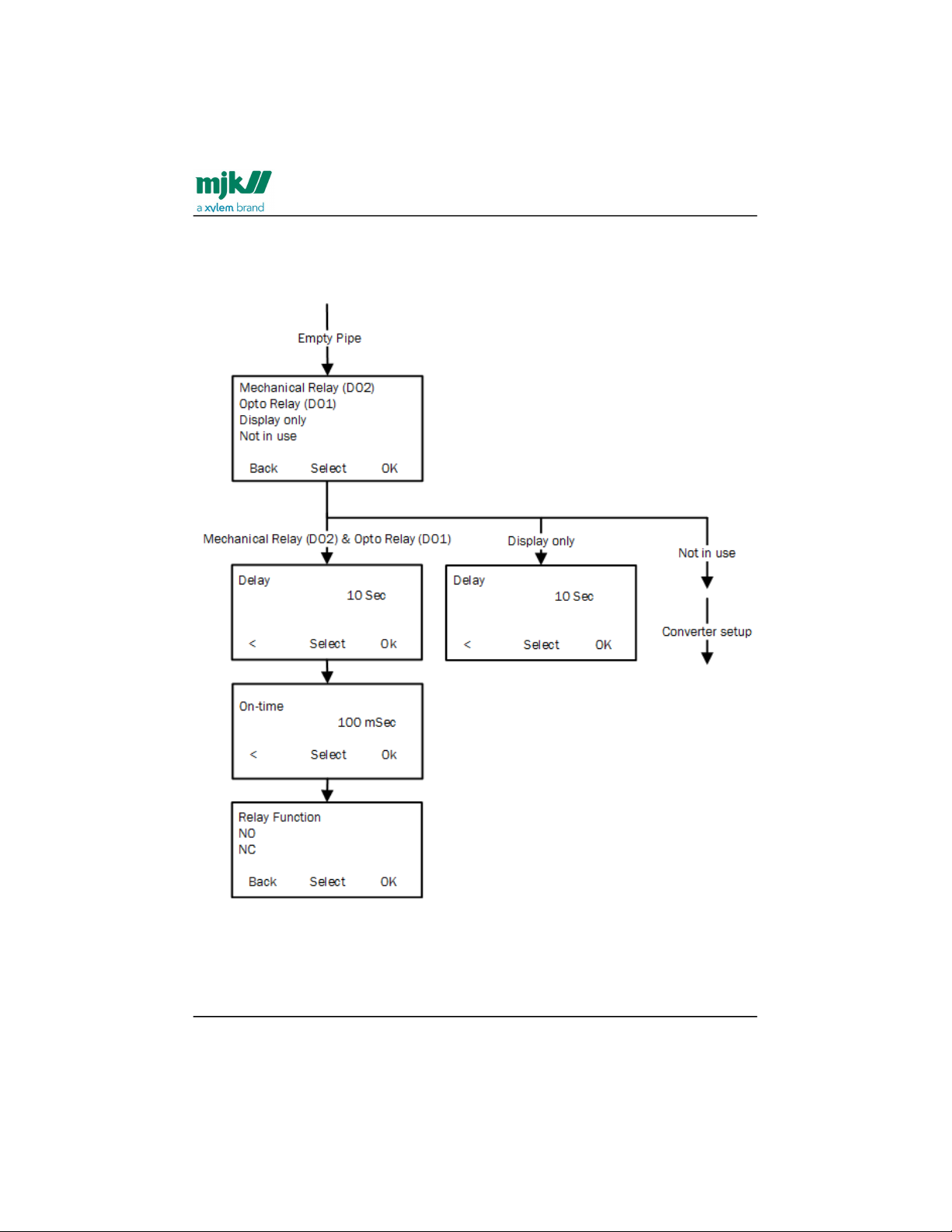
MagFlux® Series
EN 3.05 Version 2105
MagFlux® menus /Converter setup
94
•
•
•
Empty pipe
A signal and/or an alarm can be set, when the sensor becomes practically empty (see
also Pipe system(see page23)), or if the conductivity drops below 5 µS/cm.
The available output options for Empty Pipe are:
Mechanical Relay (DO2)
Opto Relay (DO1) (light-triggered electronic relay)
Display only (signals to the display unit only)
Find Quality Products Online at: [email protected]
www.GlobalTestSupply.com
Page 95
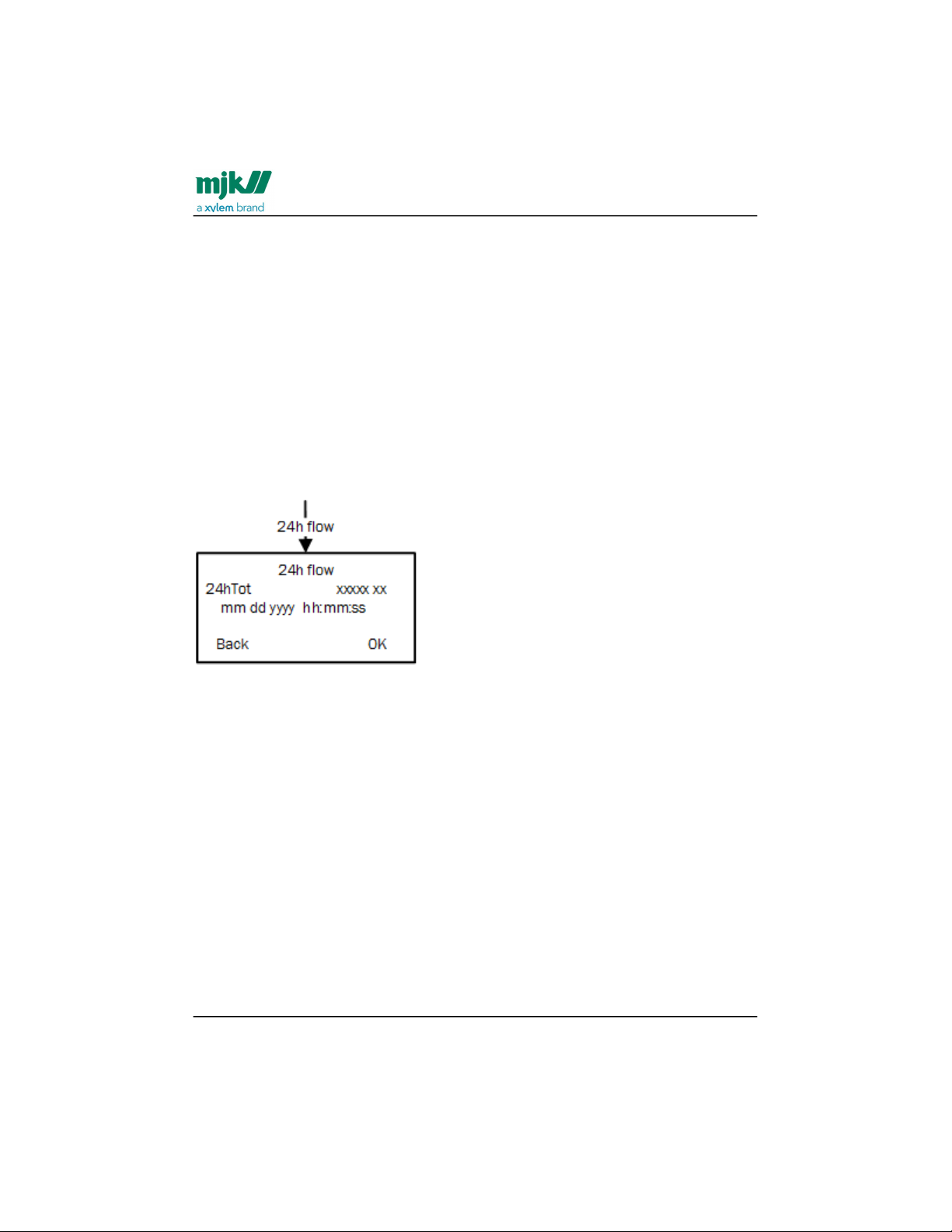
MagFlux® Series
EN 3.05 Version 2105
MagFlux® menus /Converter setup
95
•
•
•
•
•
•
•
Not in use (the Empty Pipe option is not being used)
Delay: A delay in seconds can be set to compensate for positive and negative spikes in
the flow. The length is the time between an incident and setting an alarm.
On-time: The period of time in which the relay is activated (in on-state).
Relay Function:
NO (Normally Open) determines the relay state under normal conditions.
NC (Normally Closed) determines the relay state under normal conditions.
24h flow
Measures the total flow (FTot) for 1 day (24 hours) and logs at midnight (12 PM).
NB! It takes up to 48 hours form power on before a valid value can be viewed from the
log.
Status
The Status option provides an overview of the in- and output status. The check-boxes
can contain four different characters to indicate the current status at that very moment:
X: A cross (X) in a check box indicates an active state
/: A blinking forward slant (/) indicates that the input/output is in the process of
being activated. Eventually, it turns into a steady X.
\: A blinking backward slant (\) indicates that the input/output is in the process of
being deactivated. Eventually, the check box is cleared
An empty check box indicates a deactivated state.
Find Quality Products Online at: [email protected]
www.GlobalTestSupply.com
Page 96
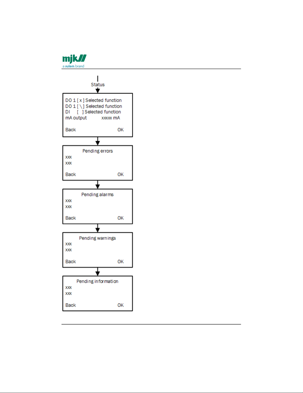
MagFlux® Series
EN 3.05 Version 2105
MagFlux® menus /Converter setup
96
Find Quality Products Online at: [email protected]
www.GlobalTestSupply.com
Page 97

MagFlux® Series
EN 3.05 Version 2105
MagFlux® menus /Converter setup
97
•
•
•
•
•
The available output options for Status are:
DO1: Status for Digital Output 1.
DO2: Status for Digital Output 2.
DI: Status for Digital Input.
mA output: The present analog output current in mA.
Pending errors: Lists pending errors.
Pending alarms: Lists pending alarms.
Pending warnings: Lists pending warnings.
Pending information: Lists pending information.
Service menu
The Service Menu provides options intended for service personnel during installation,
calibration, operation, monitoring and maintenance. All parameters can be read without
any restrictions, but certain parameters can only by changed after a password has been
typed.
Sersor calibration code
Each and every MagFlux® has a unique calibration code that contains calibration data
for the specific unit. A calibration code could for example be dw5uq4 or 7v3ri0. The
current MagFlux® converter firmware requires an 8-character input, but it also accepts 6
characters plus two OK's. If the code is dw5uq4, enter:
d w 5 u q 4 OK OK
where OK indicates that you press the OK key without selecting any character. Only
lower case letters can be entered from the MagFlux® keypad.
Important: All letters are lower case letters (e.g. a and not A), and numbers are numbers
(e.g. 0, zero and not lower case o). A potential source of error is incorrect reading of
numbers and letters, where a lower case o is confused with a zero (0), or a lower case l is
confused with the number one (1).
NB! This menu items is usually only used once, when first employing the MagFlux®.
However, it can be used later to change the flow direction if needed.
Set Flow Direction: Used to indicate the direction of the flow in the pipe to
which the MagFlux® is mounted. The default flow direction is A. See the section
on product identification regarding the calibration code and where to find it. A
password is not required to add or change the sensor calibration code.
Find Quality Products Online at: [email protected]
www.GlobalTestSupply.com
Page 98
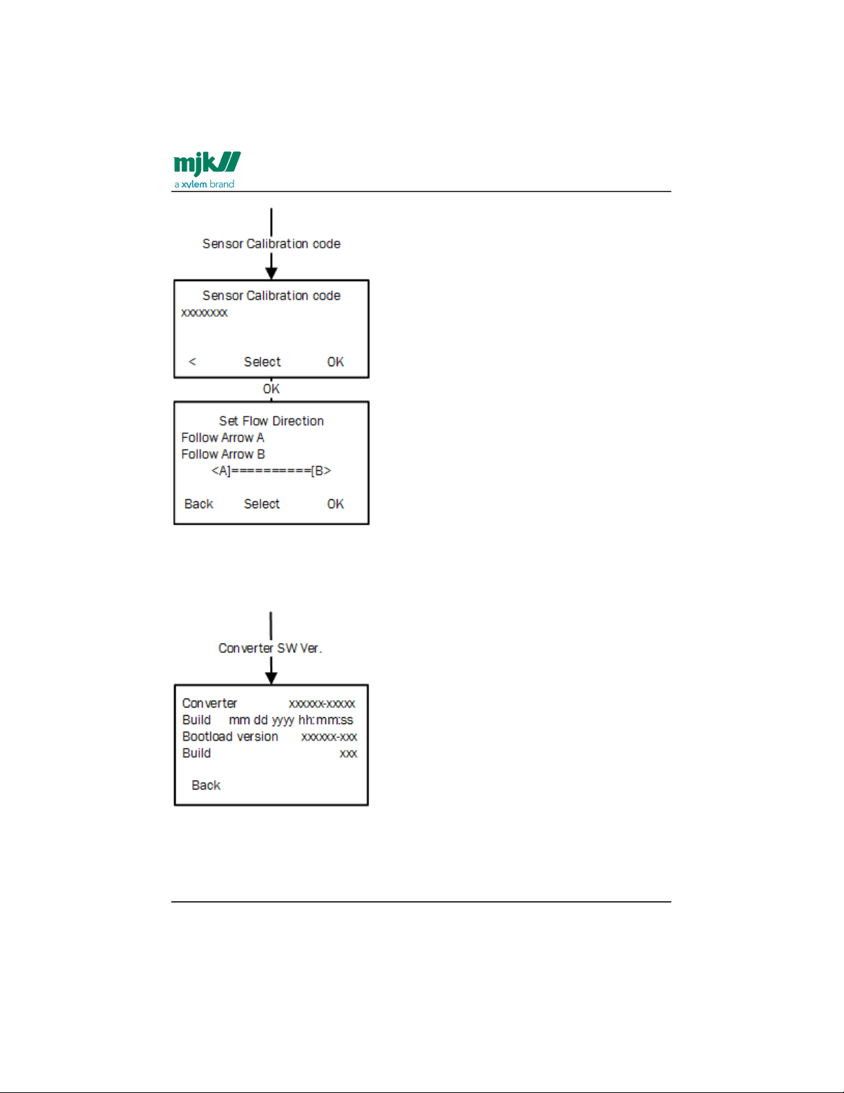
MagFlux® Series
EN 3.05 Version 2105
MagFlux® menus /Converter setup
98
Converter software ver.
The converter software version and bootload version are displayed, so that you can
determine whether a software (firmware) upgrade is required or not.
Find Quality Products Online at: [email protected]
www.GlobalTestSupply.com
Page 99
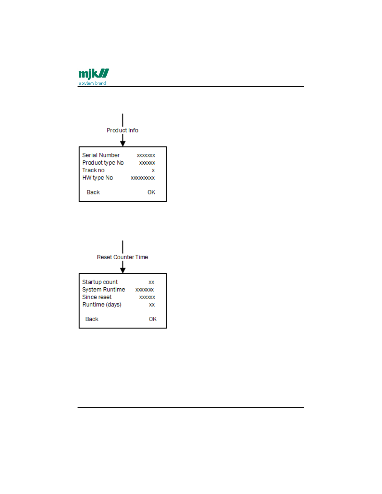
MagFlux® Series
EN 3.05 Version 2105
MagFlux® menus /Converter setup
99
Product info
Key product data like serial number, hardware type no., track no., etc. are displayed.
Reset counter time
The counter reset and run-time can be reset for fault finding, error correction and similar
service procedures.
Find Quality Products Online at: [email protected]
www.GlobalTestSupply.com
Page 100
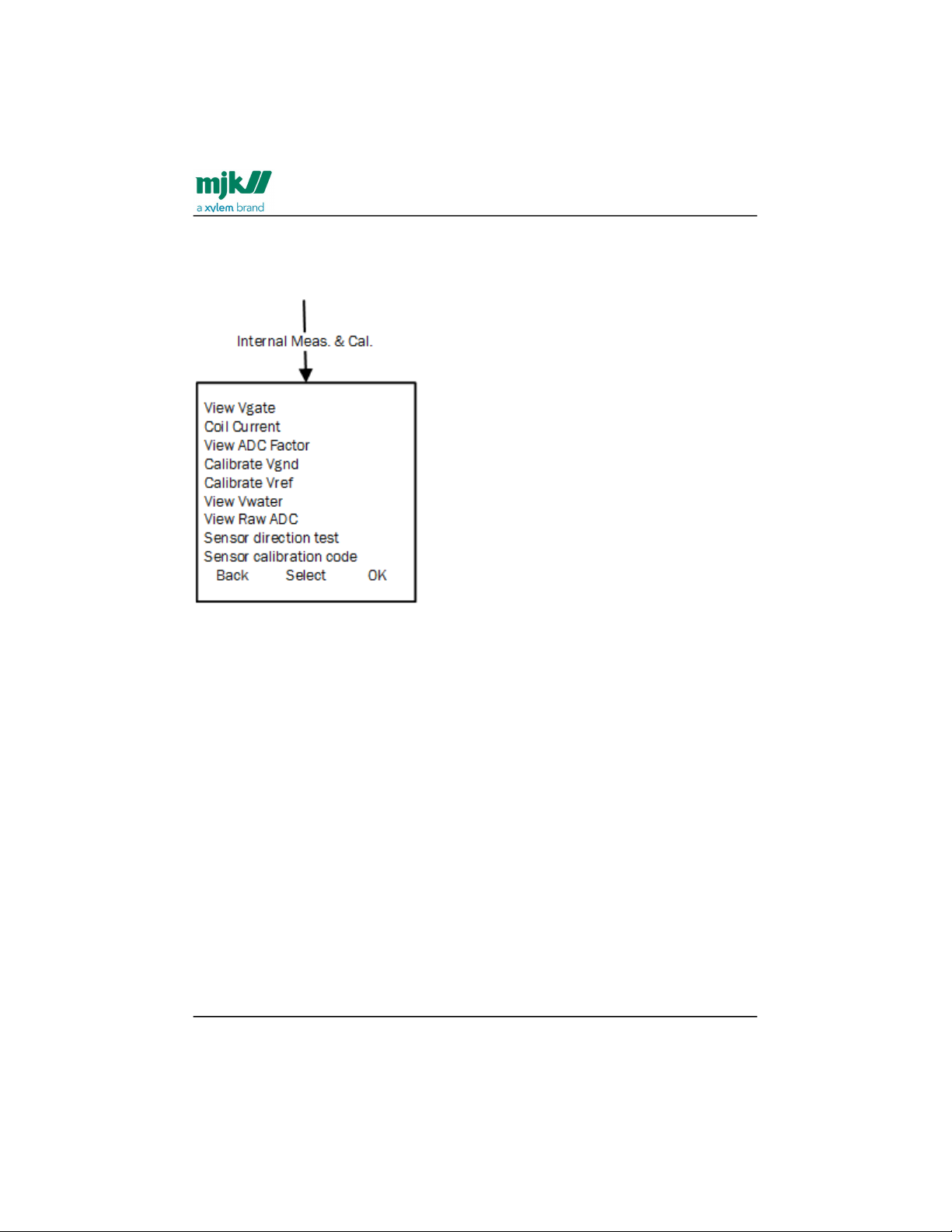
MagFlux® Series
EN 3.05 Version 2105
MagFlux® menus /Converter setup
100
1.
2.
3.
Internal meas. & cal.
For our service technician's use only. Internal measurements and calculations used for
adjustments and calibrations.
Minimum velocity
Sets the minimum forward and reverse flow velocity. MagFlux® flow meters are default
set to 0,1 m/s. For other values, see Sizing Chart(see page20). You can set both the
forward and reverse minimum flow. By setting the minimum flow, you indicate when the
MagFlux® flow meter should stop measuring.
The value under the selected item indicates the flow volume at the selected unit.
Select the digits one by one with the left/right keys and set the value with the up/
down keys.
When you press OK, Reverse and Forward will change places and you can edit
the other one.
Press OK to save.
Find Quality Products Online at: [email protected]
www.GlobalTestSupply.com
 Loading...