

Page 1
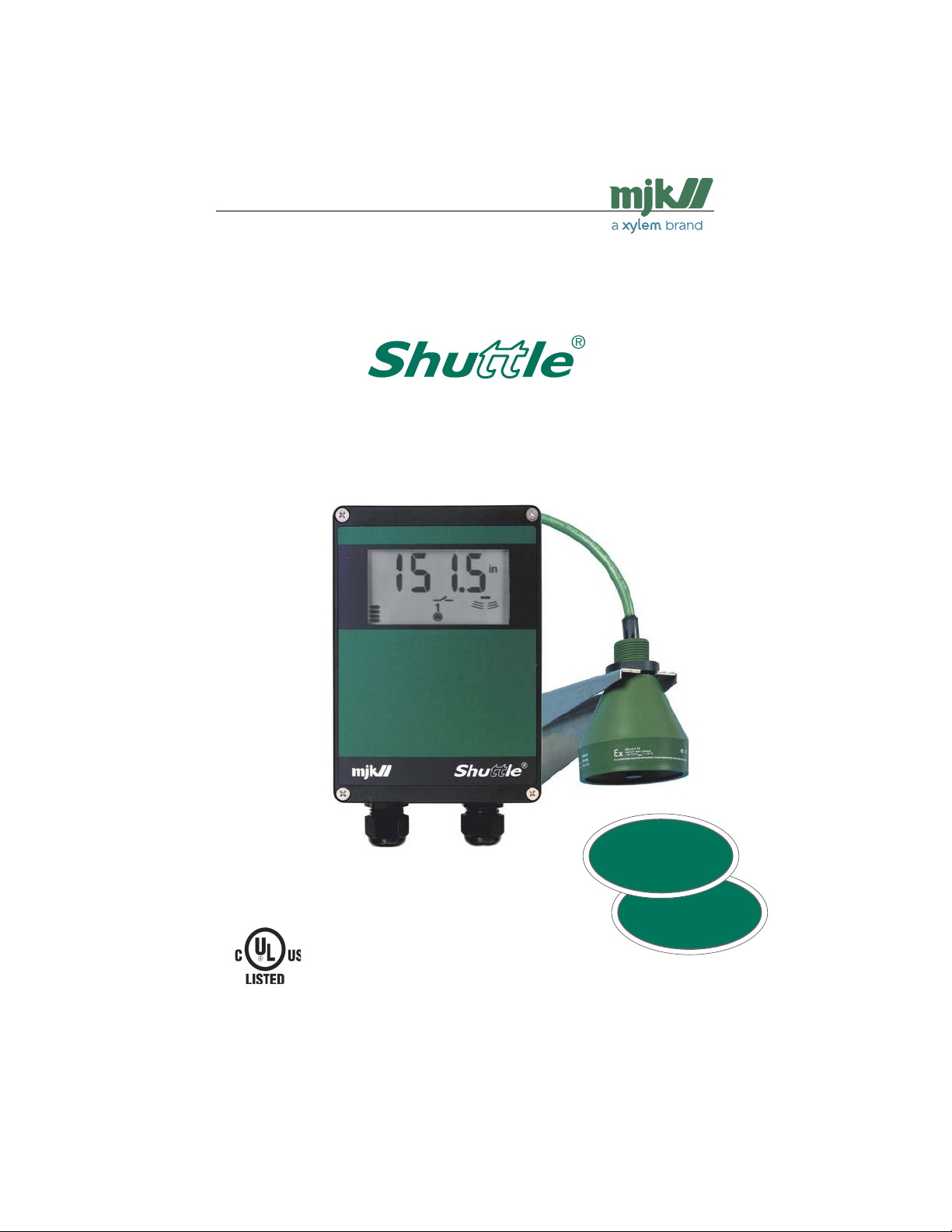
Shuttle® - Ultrasonic Level Transmitter
Ultrasonic Level Transmitter
and Sensor
New
All MJK’s newest ultrasonic
sensors covered and described
in this manual
User Manual
(FILE # E 194021)
US 2.10 Shuttle Manual 1510
Find Quality Products Online at: [email protected]
www.GlobalTestSupply.com
1
New setup procedure.
See page 14 for choosing correct
sensor type at initial setup.
SW 838023
Page 2

Shuttle® - Ultrasonic Level Transmitter
Konformitätserklärung
Declaration of Conformity
Konformitetserklæring
CE
IMPORTANT
The first time power is applied to the mounted Shuttle® level transmitter and ultrasonic
sensor, the level transmitter must be configured for the connected sensor type.
The procedure is located on page 14, "Applying power".
If, at a later time, another or a newer sensor type is connected to the transmitter,
the level transmitter must be re-configured accordingly.
The procedure is located on page 69, "Appendix F New sensor / changing sensor".
Vi, MJK Automation ApS,
DK-2850 Nærum, påtager os
det fulde ansvar for at produktet
We, MJK Automation ApS,
DK-2850 Naerum, declare under
our sole responsibility that the
product
Wir, MJK Automation ApS,
DK-2850 Naerum, erklären in alleiniger Verantwortung, dass das
Produkt
MJK Ultrasonic Sensors
auf das sich diese Erklärung
bezieht mit der/den folgenden
Nor me(en) oder normativen
Dokument(en) übereinstimmt.
Gemäss den Bestimmungen der
Richtlinie
Declaración de Conformidad
Nosotros, MJK Automation ApS,
DK-2850 Naerum, declaramos
bajo nuestra única responsabilidad que el producto
al cual se refiere esta declaración, está en conformidad
con la(s) siguente(e) norma(s) u
otros documentos normativos
según las disposiciones de la(s)
directiva(s)
som denne erklæring angår, er
i overensstemmelse med følgende standard(er) eller andre
normdokument(er).
EN 61000-6-1 2007-01-31 • EN 61000-6-3 2007-02-19
efter bestemmelserne i
direktiv
Declaration de conformite
Nous, MJK Automation ApS,
DK-2850 Naerum, déclarons
sous notre seule responsabilité
que le produit
auquel se réfère cette déclaration est conforme á la (aux)
norme(s) ou autre(s) document(s)
normatif(s)
EN 61000-6-1 2007-01-31 • EN 61000-6-3 2007-02-19
conformément aux dispositions
de Directive
to which this declaration relates
is in conformity with the following
standard(s) or other normative
document(s).
following the provisions of
Directive
89/336/EEC, 1999/5/EC, 2004/108/EC
Dichiarazione di conformità
Noi, MJK Automation ApS,
DK-2850 Naerum, dichiariamo
sotto la nostra esclusiva responsabilità che l’apparecchio
MJK Ultrasonic Sensors
al quale questa dichiarazione si
riferisce, è conforme alla seguente normativa(e) standard o ad
altri documenti di normativa(e)
conformemente alla disposizioni
della Direzione
89/336/EEC, 1999/5/EC, 2004/108/EC
28.08.2013
June 2007
Jens Kruse
UL
This product is UL-CUL listed, file # E 194021.
Ex approval of ultrasonic sensors
®
Shuttle
ultrasonic sensors are approved for mounting in explosive amospheres.
Types 200630/31/40/41: FM Class 1, Div. 1, Group A-G
US 2.10 Shuttle Manual 1510
Find Quality Products Online at: [email protected]
www.GlobalTestSupply.com
2
SW 838023
Page 3

Shuttle® - Ultrasonic Level Transmitter
Table of Contents
Introduction .................................5
About this manual .............................5
Main sections .........................................5
Illustrations .............................................5
Safety instructions .............................6
Repair ....................................................6
Ex equipment .........................................6
Product identification .........................6
Mounting ......................................7
General .............................................7
Explosion hazardous areas ................7
Mechanical mounting ........................7
Level transmitter .....................................7
Ultrasonic sensor ....................................8
Electrical mounting ............................9
Level transmitter .....................................9
Ultrasonic sensor ..................................10
Cutting the cable ..................................10
Display and keyboard ...............11
General ...........................................11
The display symbols ........................12
Displayed during programming .............12
Displayed during normal service ...........12
The keyboard .................................. 13
Basic settings .......................................13
Special settings ....................................13
Get started .................................14
Applying power to Shuttle® .............14
Sensor type selection ...........................14
- the well is empty… .............................15
- the well is not empty… .......................15
Basic settings ............................16
Units of measurement ..........................17
Sensor and zero point distance ............18
Level read-out ......................................19
The well is not empty ............................19
mA output ............................................20
Relay outputs .......................................21
Selection of relay 1 and 2 .....................21
Pump control with relay 1 and 2 ...........22
Level control with relay 1 ......................23
System alarm on relay 1 .......................24
Selection of relay function for relay 2 .....25
Level control with relay 2 ......................26
System alarm on relay 2 .......................27
Start of the learning function ............28
First time activation ...............................28
Activating the learning function ........29
Activation / deactivation ........................29
Settings ......................................30
User settings ................................... 30
User and factory settings ..........30
Factory settings ...............................30
Possible settings .............................31
Trouble shooting ........................32
General ...........................................32
Indications on system errors ............32
Normal read-out ...................................32
Too weak or missing echo ....................32
System (sensor) error............................32
Temperature error .................................32
Internal stack error ................................32
EE-PROM error ....................................33
Power failure.........................................33
Trouble shooting table .....................33
Ex Instructions ...........................35
US 2.10 Shuttle Manual 1510
Find Quality Products Online at: [email protected]
www.GlobalTestSupply.com
3
SW 838023
Page 4

Shuttle® - Ultrasonic Level Transmitter
A Tecnical specifications ................37
Dimensions ..........................................37
Shuttle® Ultrasonic Sensors ..................38
Standard Range Version .......................38
Standard Range Version/FM Approved .39
Extended Range Version ......................40
Chemical Resistant Version ..................41
B Changing supply voltage ............ 42
Conversion from 115 to 230 V AC ........42
Conversion from 230 to 115 V AC ........42
C Sensor mounting considerations 43
General ................................................43
The spread of the ultrasonic signal .......43
Measurements......................................44
Along a wall / other surface ................44
Through a concrete deck ....................44
In a tank / container ............................44
Through pipe for foam protection .......44
D Service menu ............................. 45
E Special menus ............................ 46
Bar graph read-out ...............................47
Active measuring range ........................48
Response time .....................................49
Measuring method (application) ............50
mA output signal during system error ...51
Calibration of the level measurement ....52
Offset level readout ...............................53
Indication of echo quality ......................54
Indication of signal amplification ............55
Indication of time period without echo ..56
Select factory settings ..........................57
Access code ........................................58
Readout of version numbers .................59
Find zero level at next power-up ...........60
Fixed mA signal ....................................61
Investigative measurement intervals ......62
System alarm delay ..............................63
Averaging the level measurement .........64
Max. amplification level .........................65
Min. level for accept of ultrasonic echo .66
Sensitivity of the learning function .........67
Changing the access code ...................68
F New sensor / changing sensor ... 69
Open the choose sensor menu.............69
US 2.10 Shuttle Manual 1510
Find Quality Products Online at: [email protected]
www.GlobalTestSupply.com
4
SW 838023
Page 5
Shuttle® - Ultrasonic Level Transmitter
Introduction
Thank you for choosing the MJK Shuttle®
Ultrasonic Level Transmitter.
We have done everything possible to make
a level transmitter that can fulfill all your
demands.
®
Shuttle
is suitable for all kinds of level measurements with ultrasound and can control
and supervise levels in wells and tanks
- including aggressive and polluted media.
The level meter is both easy to install and
put into service, but read this manual first then you will get the most benefits from the
®
Shuttle
Ultrasonic Level Transmitter right
from the beginning.
You can always contact your representative
or the MJK Service Hotline for advice and
guidance. Also, take a look at
®
Shuttle
is registered trademark of MJK.
About this manual
Main sections
This manual is divided into the following
three main sections:
1:
Introduction
presentation of the Shuttle® and this
manual
2: Mounting
information for performing mechanical
and electrical mounting.
3: Basic settings
a look through the most common set-
tings
Illustrations
All the Shuttle
®
display read-outs are illustrated in this manual. Some of the display
segments will flash, and in this manual the
display read-outs with flashing segments are
coloured white and the fixed segments are
coloured black.
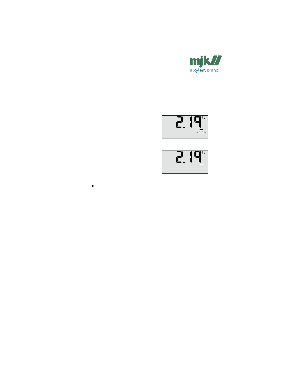
Example: Normal display read-out -
none of the segments are flashing.
Example: Missing echo -
the bar on the right hand side is flashing.
Section "Display" gives a more detailed
description of the display symbols shown
during programming and during normal
service. Furthermore, the menu explanations
show all the display indications belonging
to the specific menu during programming of
the Shuttle® Ultrasonic Level Transmitter.
US 2.10 Shuttle Manual 1510
Find Quality Products Online at: [email protected]
www.GlobalTestSupply.com
5
SW 838023
Page 6
Shuttle® - Ultrasonic Level Transmitter
Safety instructions
1: Read this manual carefully.
2: Be aware of the environment at the in-
stallation site. Wear necessary protective
equipment and follow all current safety
regulations.
3: Shuttle® can provide a start signal for
dangerous machinery. Always ensure
that connected machinery and other
equipment are effectively being put
out of service (i.e. removal of main
fuses, lock main- and/or security
switches in off position) before commencing setting, fault finding, service
and maintenance work etc.
4: There is a risk of lethal electrical shock
from terminal 1 to 5 and L-N. Be careful
not to touch these while Shuttle® is in
service.
Repair
1: Repair of Ex approved equipment (ul-
trasonic transmitter) must only be made
by MJK or by a service representative
approved by MJK.
Ex equipment
1: All current local and national standards,
regulations regarding installation and use
of Ex approved equipment, certifications
and safety instructions for Ex equipment,
that have been used together with the
installation of Shuttle® must be strictly
observed.
Product identification
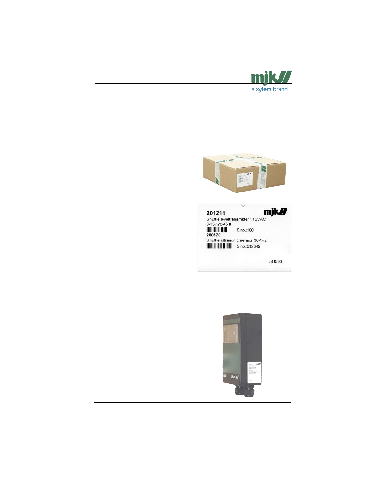
Check that the item(s) delivered corresponds to the ordered item(s). The item
number is printed on a label that is sticked
onto the packing. Shown below is the label
for a delivery including a level transmitter
and a ultrasonic sensor:
➀
➁
➀
➂
➁
➂
➀ Item number
➂ Serial number
➁ Item description
An identical marking can be found on the
right hand side of the level transmitter
cabinet:
US 2.10 Shuttle Manual 1510
Find Quality Products Online at: [email protected]
www.GlobalTestSupply.com
6
SW 838023
Page 7

Shuttle® - Ultrasonic Level Transmitter
Mounting
General
Shuttle® measures the level by sending an
ultrasonic signal against the surface and
measuring the delay time of the received
echo.
Although Shuttle® is equipped with a very
advanced system for eliminating measuring
errors, the ultrasonic sensor must - as much
as possible - be mounted so that the ultrasonic signal is not disturbed by liquid being
pumped in or by mixers, ladders or other
installations in the tank.
The liquid surface should also be calm and
without waves and possibly without foam
that may muffle the ultrasonic echo too
much.
Since the ultrasonic beam is extremely
narrow (3 ° - 7 ° depending on the type of
sensor), Shuttle® can be used for measurements in very narrow tanks or wells. This requires that the ultrasonic sensor is mounted
so it points absolutely vertical against the
surface - or the ultrasonic echo will simply
miss the sensor.
Explosion hazardous areas
The ultrasonic sensor is Ex approved in accordance with EN 50021:1999 and can be
mounted in Zone 2 without the need of a zener barrier. Please check local requirements
before installing in hazarduous locations.
The level transmitter (= the electronic
box with display) must not be mounted in
explosive hazardous areas.
Mechanical mounting
Level transmitter
Shuttle® is in NEMA 4X enclosure and can
be mounted outdoors directly on a wall,
a railing or a banister with mounting plate
200240 and universal bracket 200205.
Shuttle® Ultrasonic Level Transmitter
mounted directly on a wall.
Shuttle® Level Transmitter mounted on the plant
with mounting plate 200240 and universal bracket
Shuttle® must be mounted
vertically in order to observe the NE-
200205.
MA4X standard.
US 2.10 Shuttle Manual 1510
Find Quality Products Online at: [email protected]
www.GlobalTestSupply.com
7
SW 838023
Page 8
Shuttle® - Ultrasonic Level Transmitter
Ultrasonic sensor
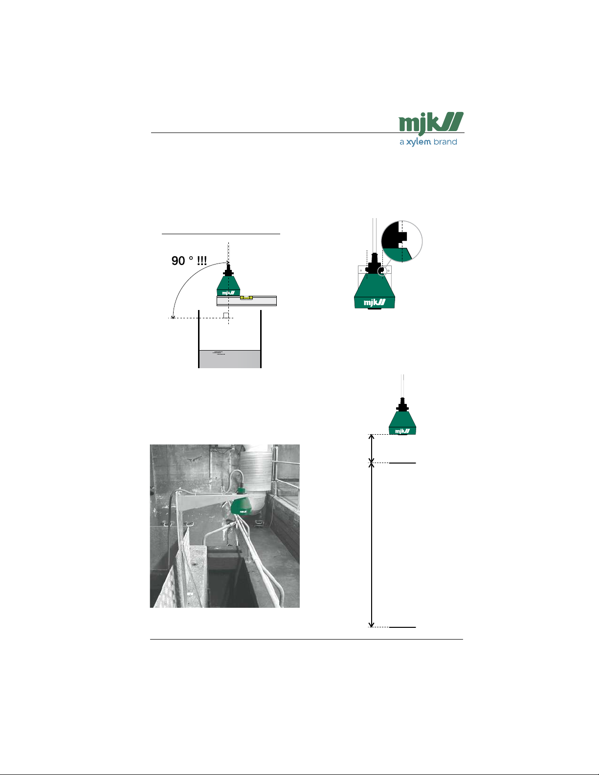
Two things are extremely important when
mounting the ultrasonic sensor: (See also
appendix C!)
1: It should be mounted securely.
2: It should be mounted absolutely vertical.
Use a spirit level in TWO directions.
To ensure a reliable and precise level measurement it
is of vital importance that the ultrasonic sensor points
down absolutely vertical against the liquid surface.
The ultrasonic sensor should be mounted
so the ultrasonic signal has no obstructions
between sensor and surface, i.e. no pipes,
cables, grates etc.
The ultrasonic sensor is equipped with a
nut for bracket mounting. Note the recess
on the nut - it must be fitted safely in the
bracket for firm fixing to the bracket:
For the highest accuracy, the ultrasonic sensor should be mounted as close as possible
to the highest possible level that can occur
+ 14 in. See below:
Min. 14 in (200570,
200640,200660)
Highest pos-
sible level
Min. 32 in (200630)
Max. measuring range:
200570: 45 ft
200640: 35 ft
200630: 75 ft
200660: 30 ft
We deliver two types of sensor brackets that can be
used in almost any installation. The bracket shown is a
standard universal mounting bracket (200220).
US 2.10 Shuttle Manual 1510
Find Quality Products Online at: [email protected]
www.GlobalTestSupply.com
8
Bottom
Total distance: Max. + Min.
SW 838023
Page 9
Shuttle® - Ultrasonic Level Transmitter
Electrical mounting
Level transmitter
The Shuttle® must not be connected to
the power supply before the ultrasonic
sensor is mounted and connected cor-
rectly.
When the cover has been removed, the
green plastic film with the menu symbols is
tipped up to gain access to the terminals.
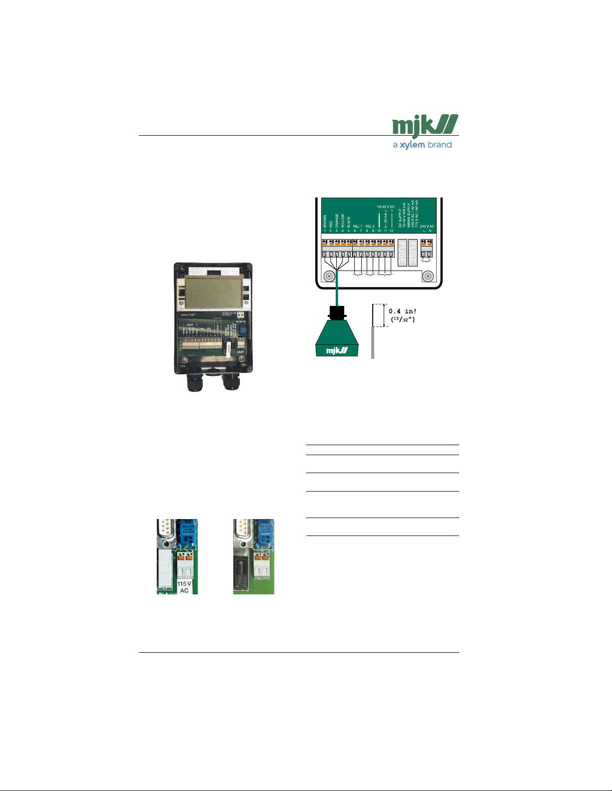
Shuttle® can be supplied with 10 - 30 V DC
on terminal 10 and 12 or with 115 / 230 V
AC on terminal L and N.
Current regulations for conductor and
fuse dimensions should always be ob-
served.
Always confirm that the Shuttle® voltage
rating match the present voltage.
If Shuttle® is intended for 115 V AC supply,
it will be indicated with a label below the
rightmost terminal block as shown here:
Mount the wires according to the terminal
numbers on the back side of the green
plastic film:
The Shuttle® is equipped with spring
terminals. Tightening is not needed.
Not for connection to rigid conduit.
Terminal: Designation:
1 - 5 Ultrasonic sensor
6 - 7 Relay output 1
(Max. 50 V, 1 A resistive load)
8 - 9 Relay output 2
(Max. 50 V, 1 A resistive load)
10 and 11 4-20 mA output
(Max. 500 Ω load)
10 and 12 10 - 30 V DC supply
L 115 / 230 V AC live
N 115 / 230 V AC neutral
Ensure that minimum 0.4
in insulation is removed!
Use copper wire only. (75
°C / 167 °F)
Shuttle® is intended Shuttle® is intended
for 115 V AC. for 230 V AC.
US 2.10 Shuttle Manual 1510
Find Quality Products Online at: [email protected]
www.GlobalTestSupply.com
9
SW 838023
Page 10
Shuttle® - Ultrasonic Level Transmitter
Ultrasonic sensor
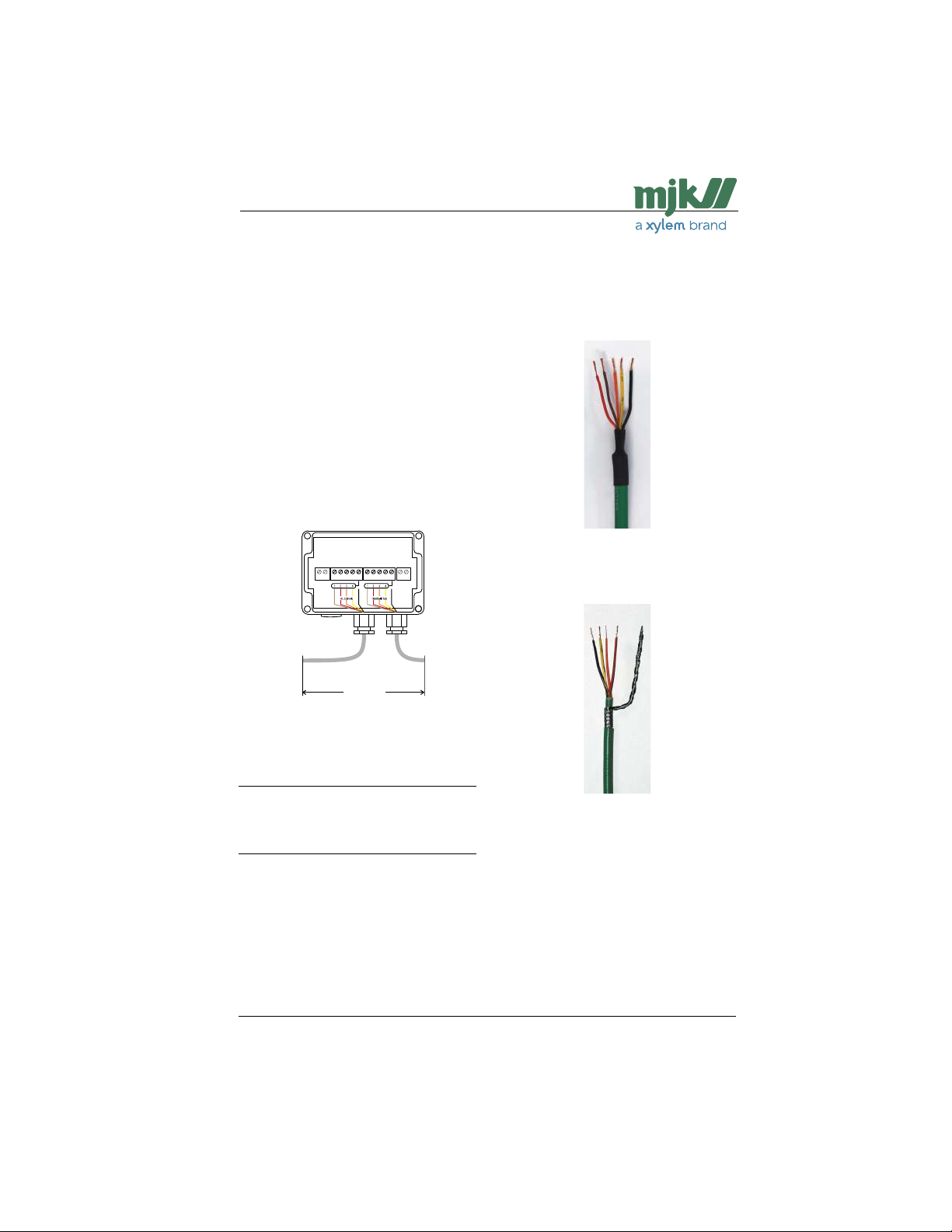
The ultrasonic sensor is delivered as
standard with 39 ft of cable. The ultrasonic
sensor can be delivered with up to 300 ft of
cable on order, or the standard 39 ft cable
can be extended to max. 300 ft.
The cable is a special low capacity cable,
so extensions should always
be made with the same type of cable.
On of the most common faults on a Shuttle®
installation is bad or faulty cable connections or using cables that dose not meet the
required specifications.
It is recommended to use connection
box 200590 if the sensor cable must be
extended.
To ultrasonic
sensor
Max.
To Shuttle
level
transmitter
300 ft !
Cutting the cable
The cable is delivered with the wires stripped as shown with the black wire (no. 5)
soldered to the shield:
When the cable is cut, only 4 wires will
appear:
®
The ultrasonic sensor cable has 5 wires with
both color code and number:
Number: Color: Designation:
1 Brown Ultrasonic pulse
2 Red
3 Orange Temperature compensation
4 Yellow
5 Black Shield ➀
➀ This wire is connected to the cable shield.
The wires are mounted according to the
terminal markings on the connection box
PCB and on the Shuttle® respectively.
US 2.10 Shuttle Manual 1510
When the cable has been cut, the shield
should be mounted in terminal 5 instead
of the black wire !
When the ultrasonic sensor is mounted and
connected correctly, the Shuttle® can be
connected to the power supply.
See section 'Get started'.
10
SW 838023
Find Quality Products Online at: [email protected]
www.GlobalTestSupply.com
Page 11
Shuttle® - Ultrasonic Level Transmitter
Display and keyboard
General
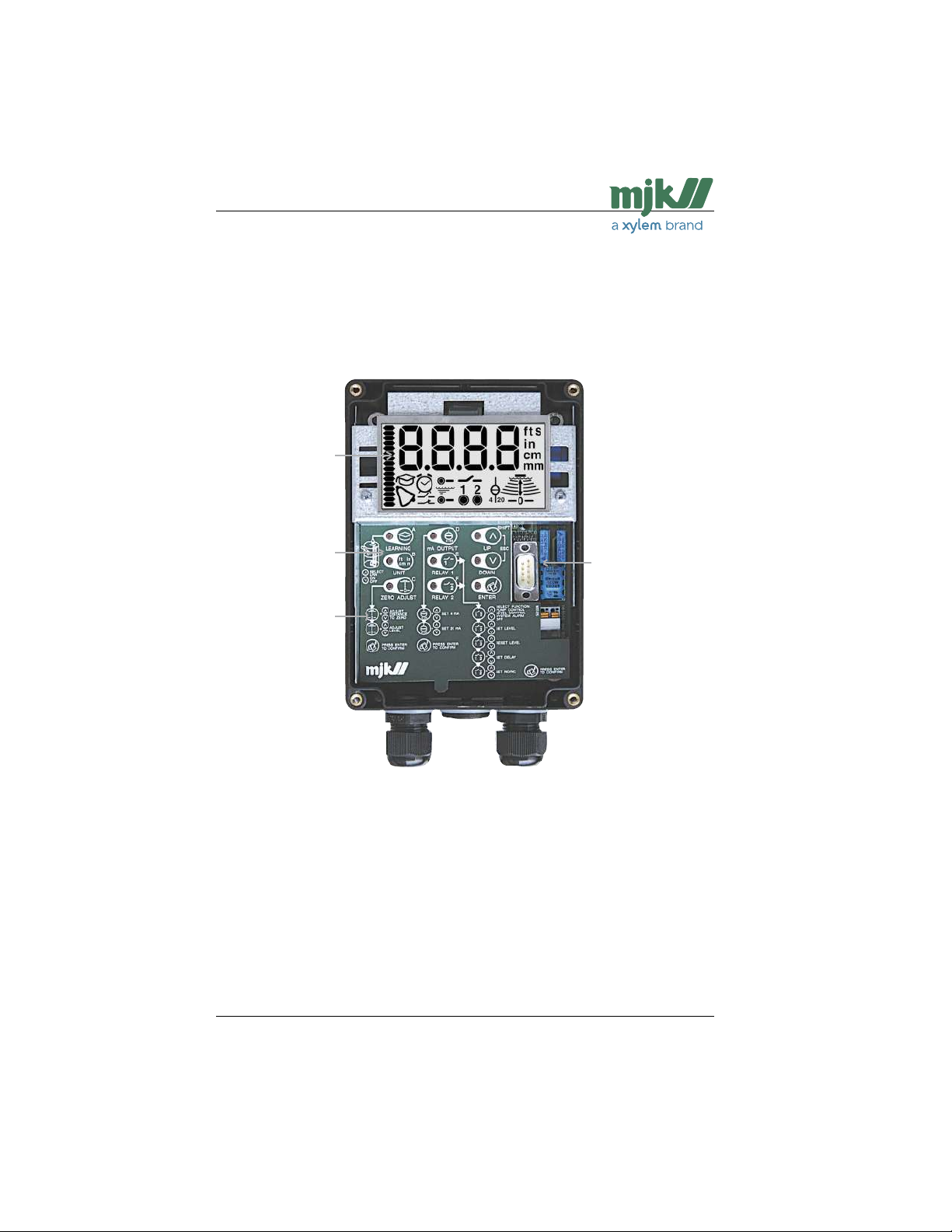
The keyboard is used only for the initial programming of the Shuttle®, and is therefore hidden
behind the front lid. The keys are marked with symbols indicating their function. The same
symbols are used throughout this manual under the explanation of the individual menus.
LCD-display with
symbols for indica-
tion during program-
ming, servicing and
normal operation.
Keyboard for
programming the
Shuttle®
A brief program-
ming instruction.
The lower part can
be tipped up to
show the connec-
tion terminals and
their designations.
Interface used during
manufacturing and
for test purposes.
US 2.10 Shuttle Manual 1510
Find Quality Products Online at: [email protected]
www.GlobalTestSupply.com
11
SW 838023
Page 12
Shuttle® - Ultrasonic Level Transmitter
The display symbols
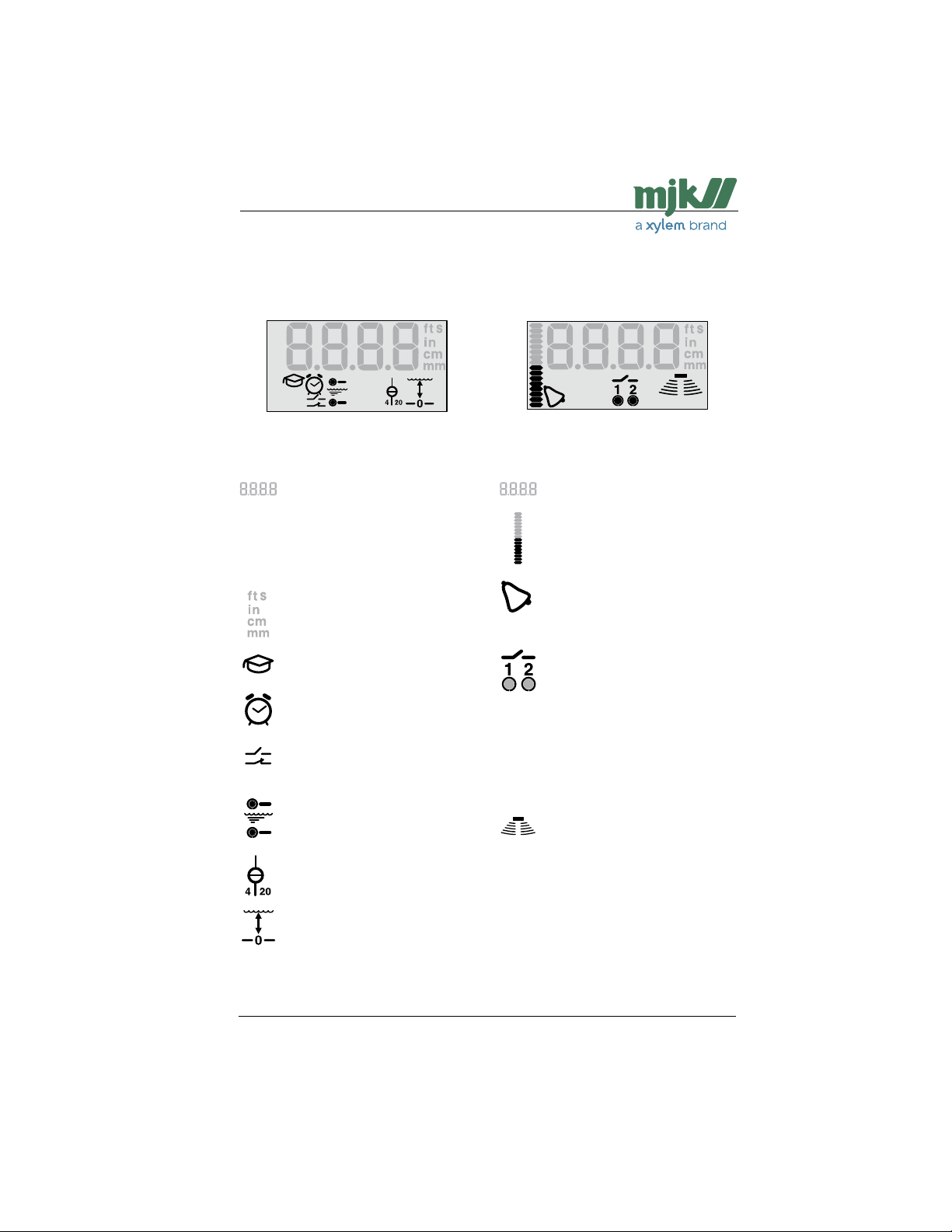
The different display segments indicates the actual level, the state of the output relays etc.
during normal service and indicates limit values, selection of measuring unit and other settings during programming.
The segments shown will be lit during
programming of the Shuttle®.
Displayed during programming
Numerical read-out of limit values.
delays and other numerical settings
and selections. Is also used to show
an initial letter code at start up of the
special settings.
See also pages 46 - 69.
Displayed when selecting the desired measuring unit (see page 17)
and when selecting time delays.
Start / activation of the learning
function. See also pages 28 - 29.
Flashes when setting the time
delays.
See also pages 22 - 24, 26 and 27.
Displayed when programming the
output relays.
See also pages 23 - 24 and 26 and
27.
Displayed when setting the start and
stop levels for the output relays.
See also pages 21 - 23 and 25 -26 .
Displayed when setting the zero
point and span for the mA output.
See also page 20.
Displayed when setting the distance
between sensor and zero point and
setting of level read-out.
See also pages 18 - 19.
The segments shown will be lit when
Shuttle® are in normal service.
Displayed during normal service
Numerical read-out of the actual
level.
Bar graph for indication of the signal
level on the mA-output or for indication of the actual level.
Alarm symbol. The symbol is shown
if a system error should occur on the
Shuttle®.
See also pages 24 and 27.
Indication of the status of the output
relays and whether the output relays
are in use. The round dot below
the relay number will appear steady
when the relay is activated and will
appear flashing when the relay is
about to be activated after a preset
time delay.
See also pages 22 - 24, 26 and 27.
This group of symbols indicates the
strength of the received ultrasonic
echo. A good measuring signal is
indicated by three or more sets of
archs.
See also page 32.
US 2.10 Shuttle Manual 1510
Find Quality Products Online at: [email protected]
www.GlobalTestSupply.com
12
SW 838023
Page 13
Shuttle® - Ultrasonic Level Transmitter
The keyboard
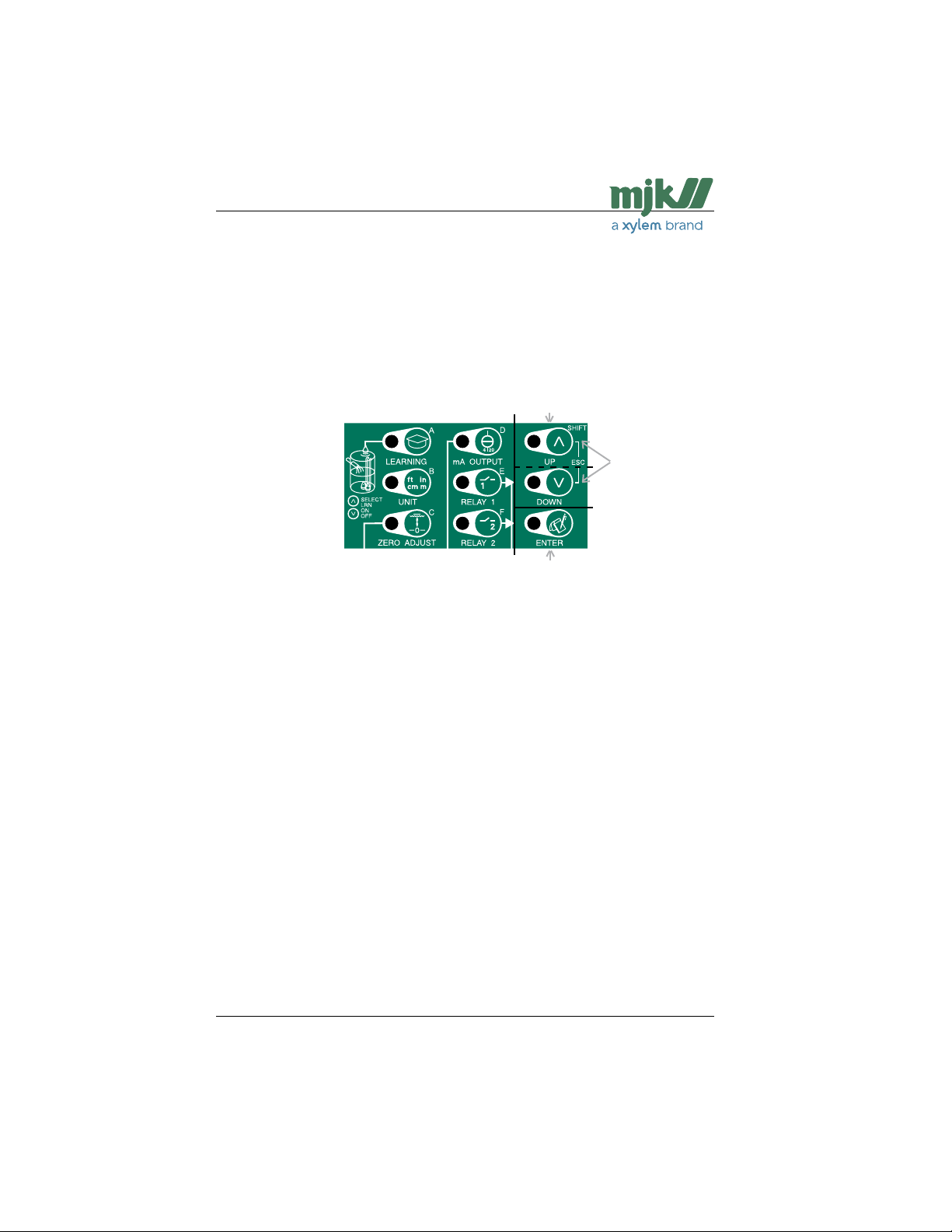
From the Shuttle® keyboard the keys marked A - F (➀) gives access to 21 menus divided in
6 basic settings and 15 special settings.
There is direct access to the menus for basic settings by pressing one the keys A to F.
See appendix E for instructions for access to the special settings.
When a menu has been selected, settings are made with the UP and DOWN keys and
the selection is confirmed with the ENTER key (➃) whereafter Shuttle® reverts to normal
read-out. To leave any menu without changing the settings, press the UP and DOWN keys
simultaneously (ESCape, ➂).
➀ ➁
➂
➃
Basic settings
A (LEARNING)
Start and activation/deactivation of the
learning function.
B (UNIT)
Selection of measuring unit.
C (ZERO ADJUST)
Setting of sensor distance and zero
point.
D (mA OUTPUT)
Setting of the mA output.
E (RELAY 1)
Setting of the functions for relay
output # 1.
F (RELAY 2)
Setting of the functions for relay
output # 2.
(see pages 14 - 28)
Special settings
Shift + A (bA - bar graph readout)
Shift + B (rA - Active measuring range)
Shift + C (rE - response time for level chan-
ges)
Shift + D (AP - Application setup)
Shift + E (S. Err - System error indication)
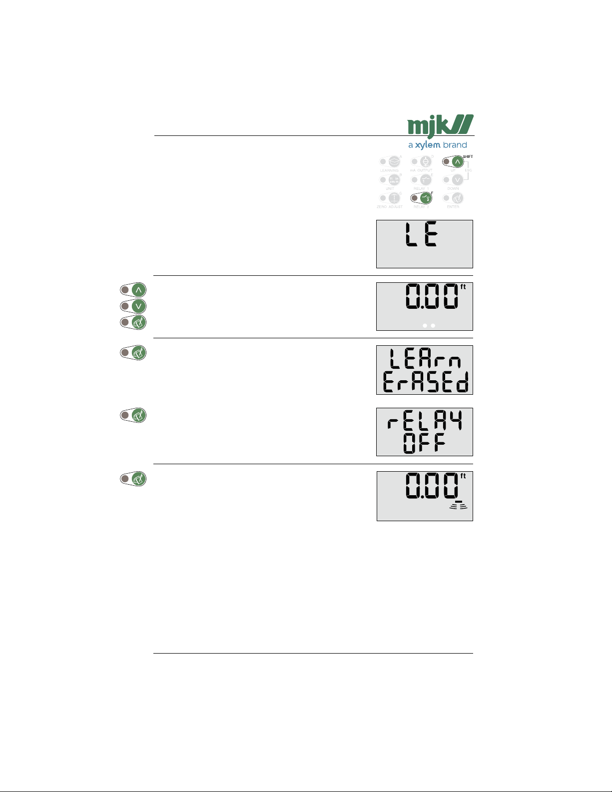
Shift + F (LE - Level readout calibration)
Esc + A (nAP - Setting of reference level)
Esc + B (Qu - Indication of signal quality)
Esc + C (Sh - Indication of signal amplifi-
cation)
Esc + D (dE - Period without echo)
Esc + E (FA - Factory settings)
AxsC + A (S. Ln - HW/SW/Serial numbers)
AxsC + B (S.St - Find zero level at next
power-up)
AxsC + C (12nA - Constant mA signal out)
AxsC + D (nS - Investigative measurements
interval)
AxsC + E (S. Al - System alarm delay)
(see Appendix E)
US 2.10 Shuttle Manual 1510
Find Quality Products Online at: [email protected]
www.GlobalTestSupply.com
13
SW 838023
Page 14
Shuttle® - Ultrasonic Level Transmitter
Get started
Applying power to Shuttle®
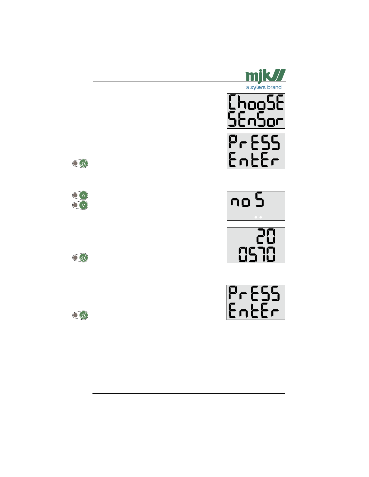
When Shuttle® is connected to power for the first time, the
following texts (Choose Sensor Press Enter) will appear
across the display:
Press "Enter" once to select the required sensor type.
Sensor type selection
When "No Sensor" (no S) is displayed, press the 'Up' or
'Down' arrow key to leaf through the different sensor types:
2005xx and 2006xx.
When the required sensor type appears on the display (here:
200570), press "Enter" once.
The sensor type is now registered by the level transmitter,
and "Press Enter" passes across the display to indicate that
you may continue with setting/measuring a level of 0 meter
(nil, empty tank).
Press "Enter" once to proceed with the initial settings.
Notes:
When a sensor type has been selected, the factory settings will have no influence on this selection.
If you choose "No Sensor" (no S), the Shuttle will
invoke the choose sensor menu at start-up. From this
point the correct sensor type can be selected.
US 2.10 Shuttle Manual 1510
14
SW 838023
Find Quality Products Online at: [email protected]
www.GlobalTestSupply.com
Page 15
Shuttle® - Ultrasonic Level Transmitter
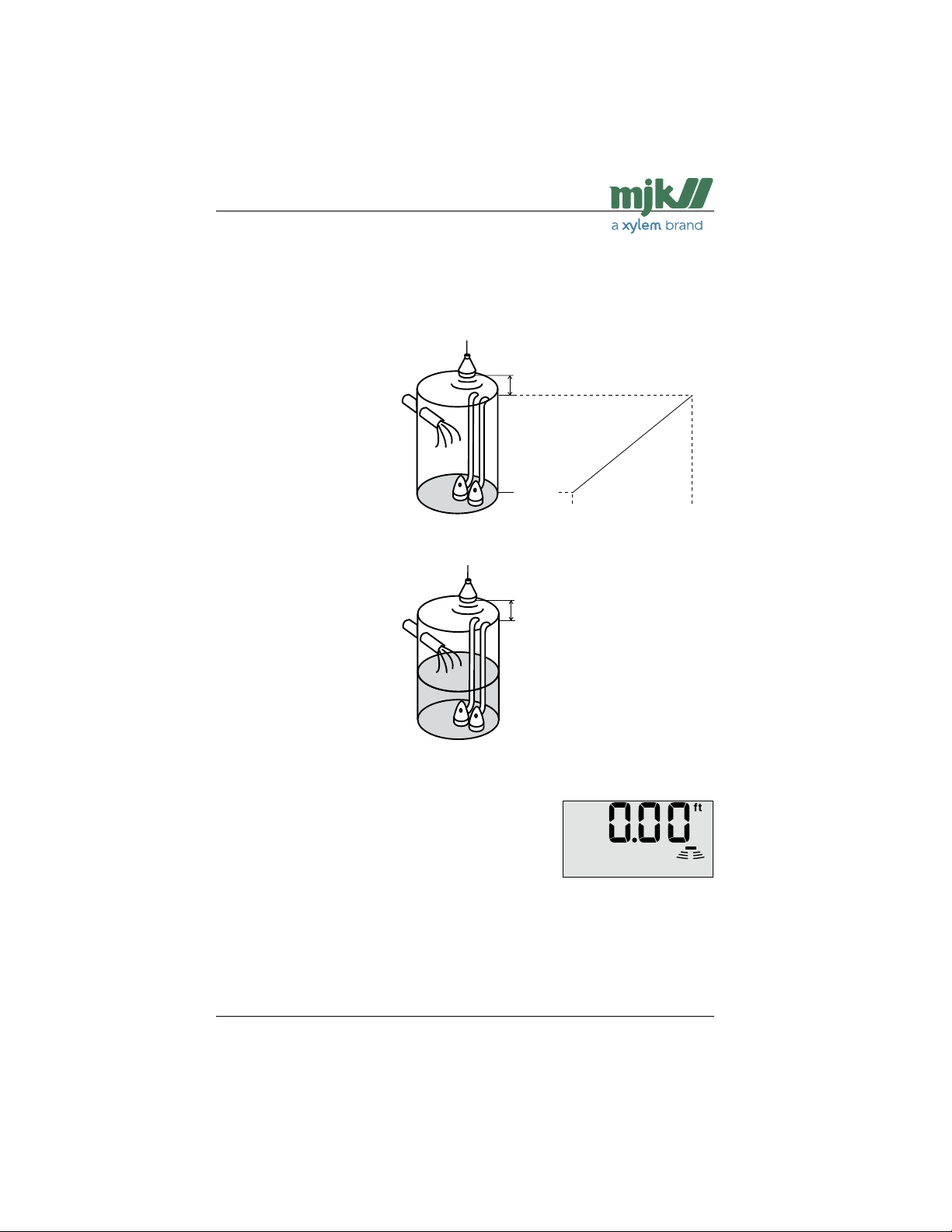
At the same moment Shuttle® registers an echo, the zero point is automatically set to the
level that is present in the tank or well.
Furthermore, the mA output is set to 4 mA at the current zero point and 20 mA at a level corresponding to a distance of 14 in from the ultrasonic sensor.
- the well is empty…
14 in from sensor (types 200570,
200640 and 200660)
32 in from sensor (type 200630)
Level read-out = distance
between sensor and bottom
- (minus) the distance between sensor and surface.
0.00 in
4 mA 20 mA
- the well is not empty…
The distance from the sensor to the zero point or the
4 in from sensor
level read-out must be set
manually - see page 13.
Note: The dead band
varies for the different
sensor types: 14 in for
types 200570, 200640 and
200660, and 32 in for type
200630.
See also Appendix A, Technical Specifications begining on
page 37.
Shuttle® will now indicate the current level in the tank or well
(0 ft immediately after initial startup) and is now in service as
a regular level meter, i.e. without the use of the relays and
the analog output for control / alarm.
See the next section for basic settings.
US 2.10 Shuttle Manual 1510
15
SW 838023
Find Quality Products Online at: [email protected]
www.GlobalTestSupply.com
Page 16
Shuttle® - Ultrasonic Level Transmitter
Basic settings
The automatic setting of the zero point and the mA output made by Shuttle® during initial
startup may be adequate.
If changes of the zero point read-out and mA output setting should be necessary, and when
Shuttle® is to be used as a pump controller or for level monitoring, an additional 5 settings
should be made. These settings are described in detail on the following pages.
Proceed with set-up in the order listed below:
1: Setting units of measurement See page 17.
2: Setting the distance from sensor to zero point and
Setting the level read-out: See pages 18 - 19.
3: Setting the mA output: See page 20.
4: Setting the the relay limits: See page 21.
5: Start of the learning function: See pages 28 - 29.
When the settings are made, Shuttle® is ready to be put into service.
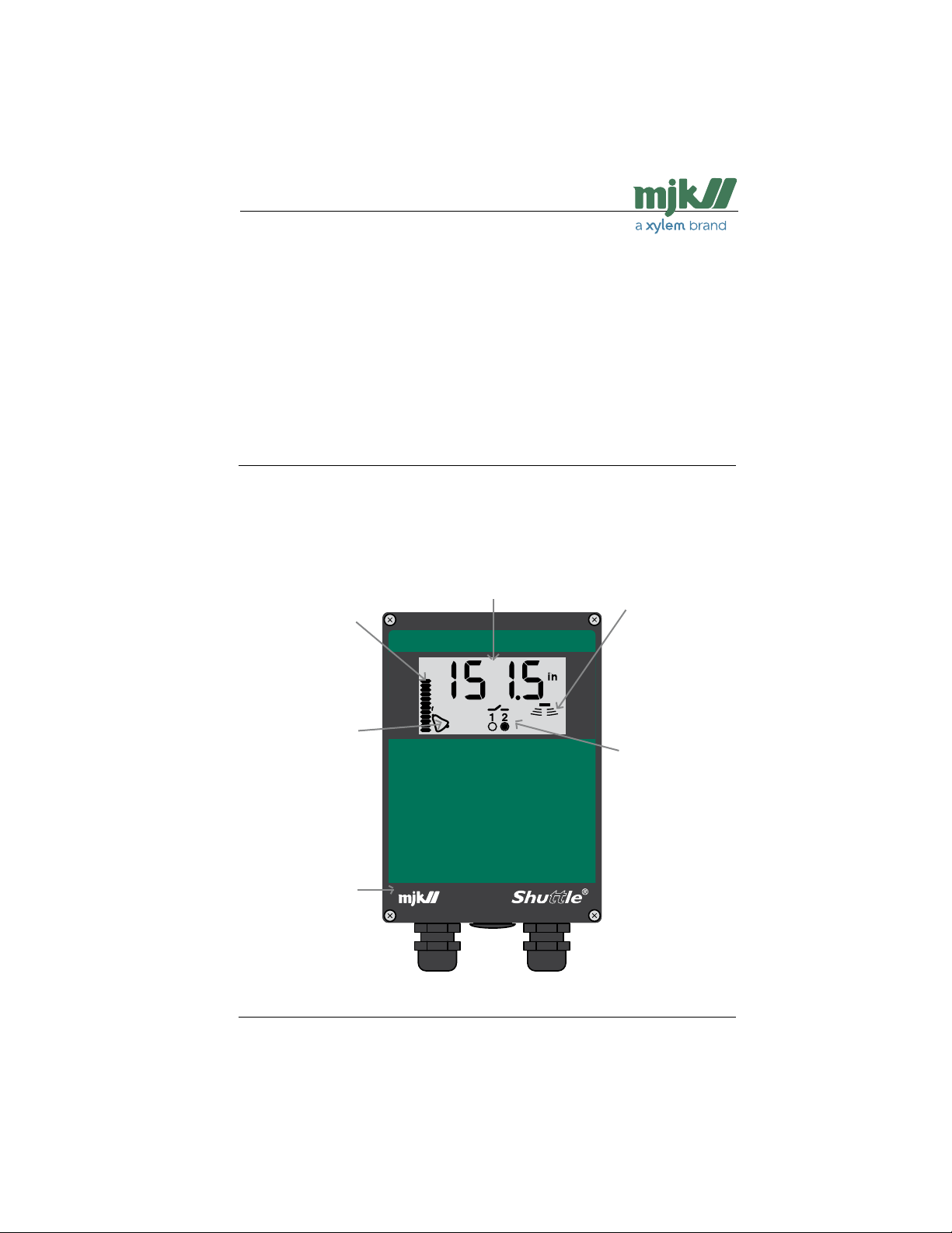
Bar graph
The bar graph can
be set to indi-
cate either the level
read-out or the mA
output.
Alarm
A flashing bell
indicates, that a
level is exceeded
or that Shuttle® is
not certain that the
measured level is
correct.
MJK
will always be at
your assistance.
Display
Shuttle® continuosly reads
out the current level with
bright and easy-to-read
figures.
Echo strength
Shuttle® indicates
that the ultrasonic
echo is sufficient
for a reliable level
measurement.
Relay outputs
When Shuttle®
measures a level
that has exceeded
a setpoint limit, the
relays are activated
and their current position are indicated
here. (Relay no. 2 is
activated.)
US 2.10 Shuttle Manual 1510
Find Quality Products Online at: [email protected]
www.GlobalTestSupply.com
16
SW 838023
Page 17
Shuttle® - Ultrasonic Level Transmitter
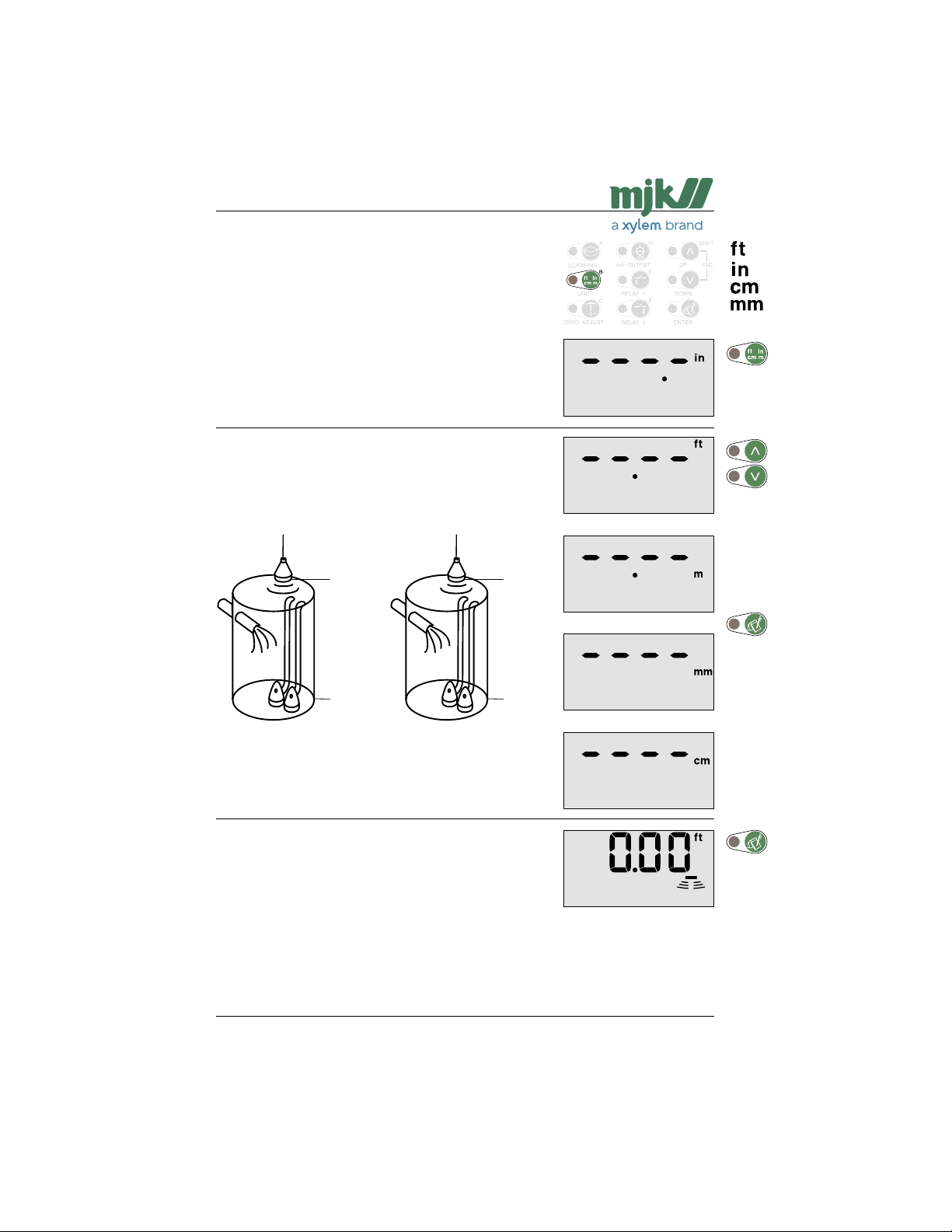
Units of measurement
If the measuring unit is changed, all other values in menus
and settings will automatically be converted to the new
measuring unit.
In this example the measuring unit is changed from feet to
inches.
The settings will be rounded off automatically.
Select unit with the arrow keys.
The dot indicates the position of the decimal separator.
6.00 ft
0.00 ft
Note: 'mm' or 'in' cannot be selected if it could cause
overrun in the display read-out.
Shuttle® reverts to normal read-out with the new measuring
unit.
72.0 in
0.0 in
US 2.10 Shuttle Manual 1510
Find Quality Products Online at: [email protected]
www.GlobalTestSupply.com
17
SW 838023
Page 18
Shuttle® - Ultrasonic Level Transmitter
Sensor and zero point distance
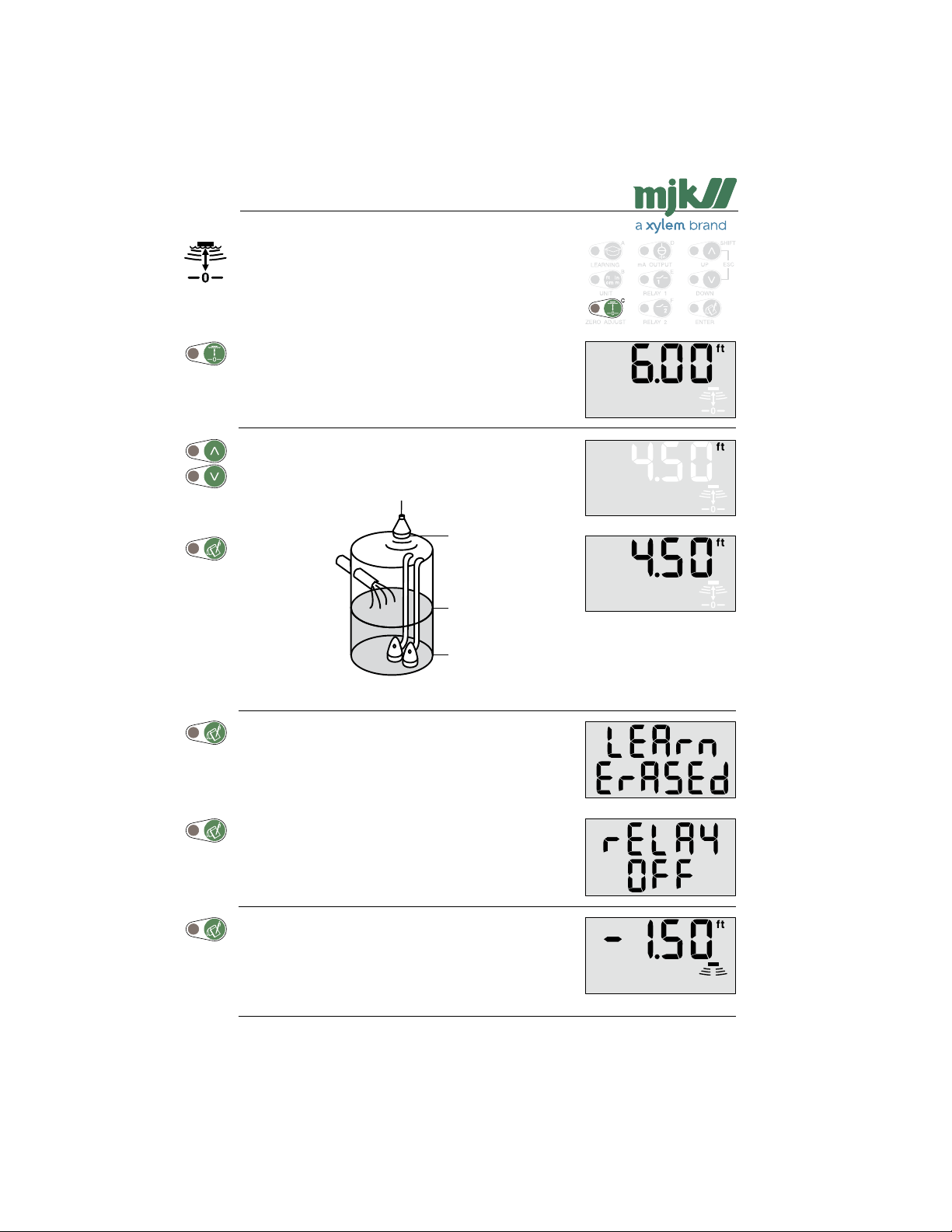
The level read-out (zero point) can be adjusted as required.
This is almost always required if the well was not empty
during initial startup.
Note: The learning function settings will be erased and
In this example, the level read-out is changed to be 1.50 ft
from the bottom of the well / tank.
Set the new zero point with the arrow keys.
the relays will be deactivated if the zero point setting is changed.
6.00 ft
1.50 ft
0.00 ft
If the learning function has been activated, Shuttle® will
deactivate the learning function and erase the suspicious
levels that were found last time the learning function was
activated.
The learning function must therefore both be started and
reactivated again.
If the relay outputs are configured for pump control, the
relays will be deactivated, but their limit settings will not be
erased. Also, delay settings and other settings will not be
erased.
Shuttle® will now read out - 1.50 ft when the well is empty.
US 2.10 Shuttle Manual 1510
18
SW 838023
Find Quality Products Online at: [email protected]
www.GlobalTestSupply.com
Page 19
Shuttle® - Ultrasonic Level Transmitter
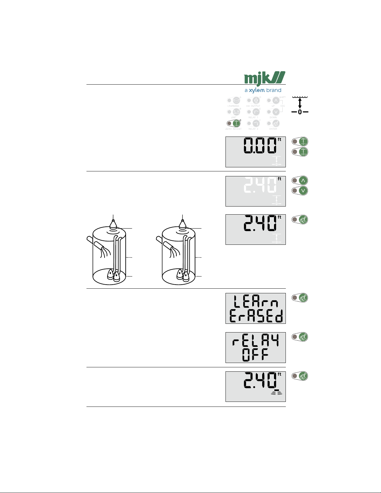
Level read-out
The well is not empty
With this function the level read-out can be increased or
decreased on demand. This is almost always required if the
well was not empty during initial startup.
Note: The learning function settings will be erased and
In this example, the actual level is 2.4 ft, but Shuttle® reads
out 0 ft.
Select the desired level read-out with the arrow keys.
Shuttle® will now read out 0.00 ft when the well is empty.
the relays will be deactivated if the zero point setting is changed.
3.60 ft
0.00 ft
- 2.40 ft
6.00 ft
2.40 ft
0.00 ft
If the learning function has been activated, Shuttle® will
deactivate the learning function and erase the suspicious
levels that were found last time the learning function was
activated.
If the relay outputs are configured for pump control, the
relays will be deactivated, but their limit settings will not be
erased.
Also, delay settings and other settings will not be erased.
Shuttle® will now revert to normal level read-out with a incre-
ased read-out value.
US 2.10 Shuttle Manual 1510
Find Quality Products Online at: [email protected]
www.GlobalTestSupply.com
19
SW 838023
Page 20
Shuttle® - Ultrasonic Level Transmitter
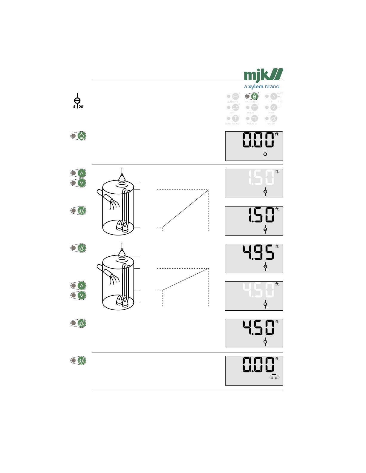
mA output
When Shuttle® is connected to the power supply for the first
time, the mA-output is automatically set to provide 4 mA at
zero level and 20 mA at a level corresponding to 14 in below
the ultrasonic transmitter.
In this example the range of the mA output is changed from
0 - 4.95 ft to 1.5 - 4.5 ft. Changes made will not affect the
relay settings.
Note: Both values can be set over the whole range thus
making it possible to decrease the mA signal at
rising levels and vice versa.
6.00 ft
4.95 ft
0.00 ft
4 mA 20 mA
6.00 ft
4.50 ft
1.50 ft
0.00 ft
4 mA 20 mA
Shuttle® reverts to normal read-out.
US 2.10 Shuttle Manual 1510
20
SW 838023
Find Quality Products Online at: [email protected]
www.GlobalTestSupply.com
Page 21
Shuttle® - Ultrasonic Level Transmitter
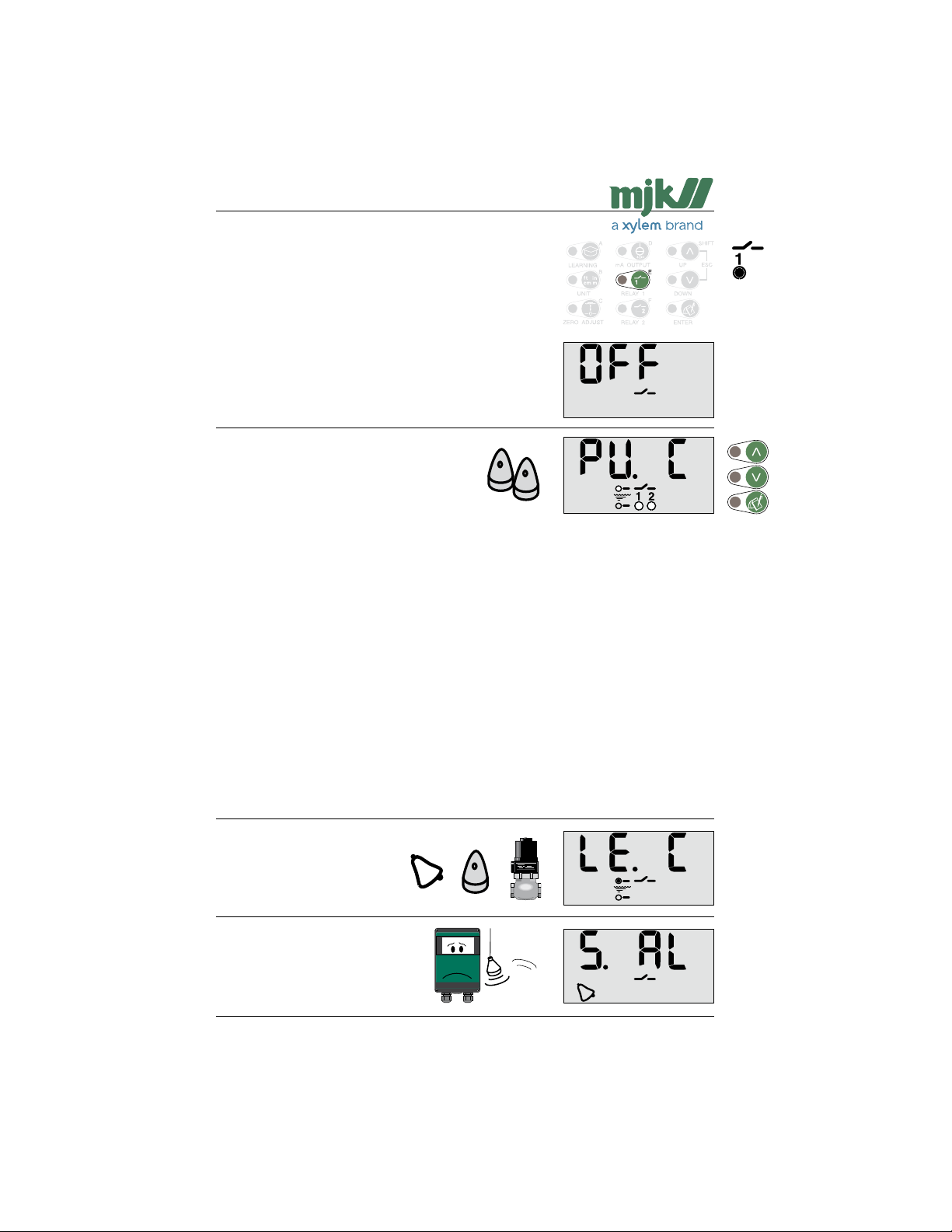
Relay outputs
Selection of relay 1 and 2
Three functions are available:
- pump control with alternation of two pumps
- level control
- system alarm
Note: If Pump Control is selected, the start and stop
If Level Control is selected, the start and stop set-
Select the desired function with the arrow keys.
Pump control:
Continue on the facing page.
settings cannot be set any closer than 4 in.
tings cannot be set any closer than ½ in.
Note: If pump control is selected, both relays are set in this menu and relay 2 will not be
The relays can control both pumping in and pumping out, but both relays will have
If it is later desired to change the setting, simply change the setting for relay 1 after
If the relays are configured for pump control, they will always be deactivated on
Level control:
See page 23.
System alarm:
See page 24.
available for other functions.
the same function. The function is selected automatically when relay 1 is set according to the start and stop levels. If the start level is set higher than the stop level,
both relays will then be configured for pumping in. On the other hand, if the start
level is set lower than the stop level, both relays will be configured for pumping in.
which the start and stop setting for relay 2 will be switched automatically.
system errors after 30 seconds independent of the selected time delay to prevent
dry run of the pumps.
US 2.10 Shuttle Manual 1510
Find Quality Products Online at: [email protected]
www.GlobalTestSupply.com
21
SW 838023
Page 22
Shuttle® - Ultrasonic Level Transmitter
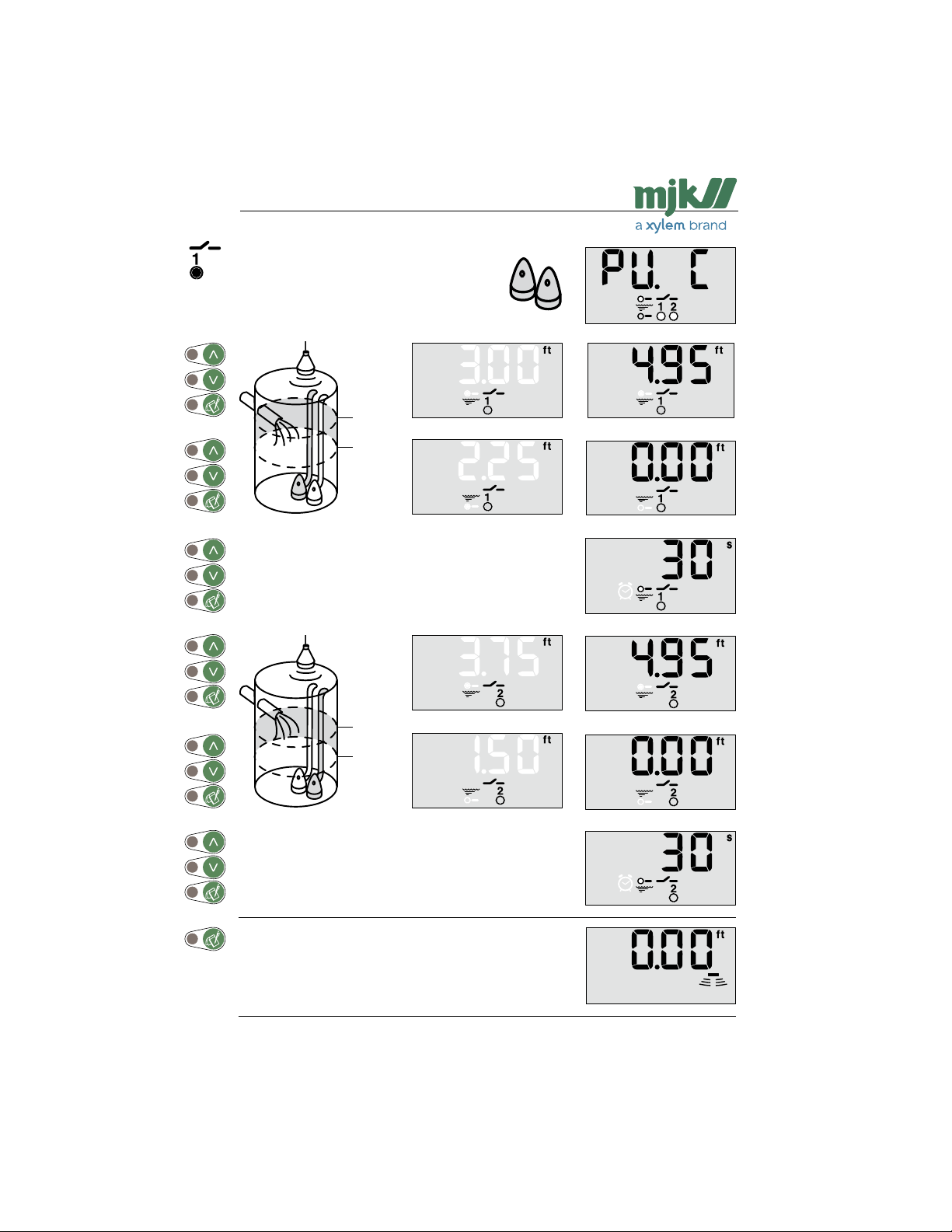
Pump control with relay 1 and 2
Start and stop level for pump no. 1 is set to 3.00
and 2.25 ft respectively.
3.00 ft
2.25 ft
Select the time delay for relay 1 with the arrow keys.
Start and stop level for pump no. 2 is set to 3.75
and 1.50 ft respectively.
3.75 ft
1.50 ft
Select the time delay for relay 2 with the arrow keys.
With these start and stop levels Shuttle® is now configured
for pumping out and reverts to normal read-out.
US 2.10 Shuttle Manual 1510
22
SW 838023
Find Quality Products Online at: [email protected]
www.GlobalTestSupply.com
Page 23
Shuttle® - Ultrasonic Level Transmitter
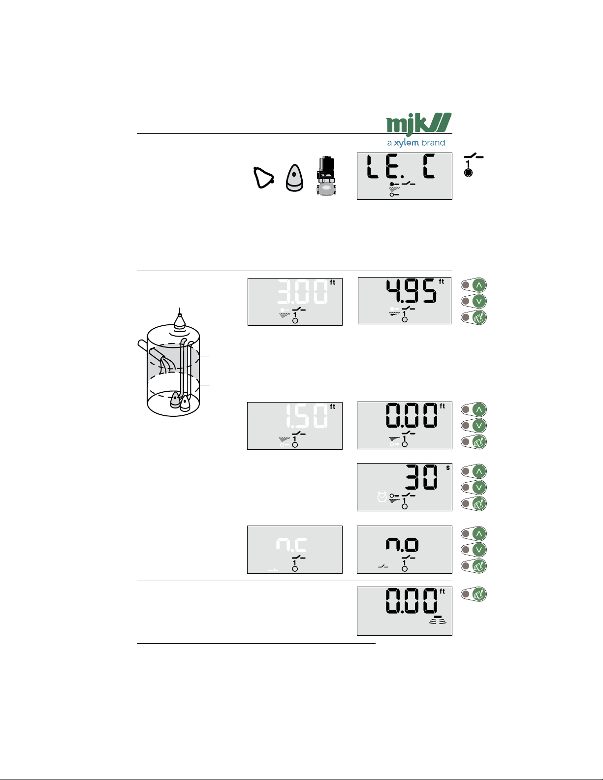
Level control with relay 1
In this menu the level for activation (set) of relay 1 is changed from 4.95 to 3.00 ft and deactivation (reset) of the relay output is changed from 0.00 to 1.50 ft.
Select the activation (set)
level for relay 1 with the
arrow keys.
3.00 ft
(activate)
1.50 ft
(activate)
Select the deactivation
(reset) level for relay 1 with
the arrow keys.
Select the time delay.
Select relay mode.
('n.c' = normally closed,
'n.o' = normally open).
Shuttle® reverts to normal read-out.
US 2.10 Shuttle Manual 1510
23
SW 838023
Find Quality Products Online at: [email protected]
www.GlobalTestSupply.com
Page 24
Shuttle® - Ultrasonic Level Transmitter
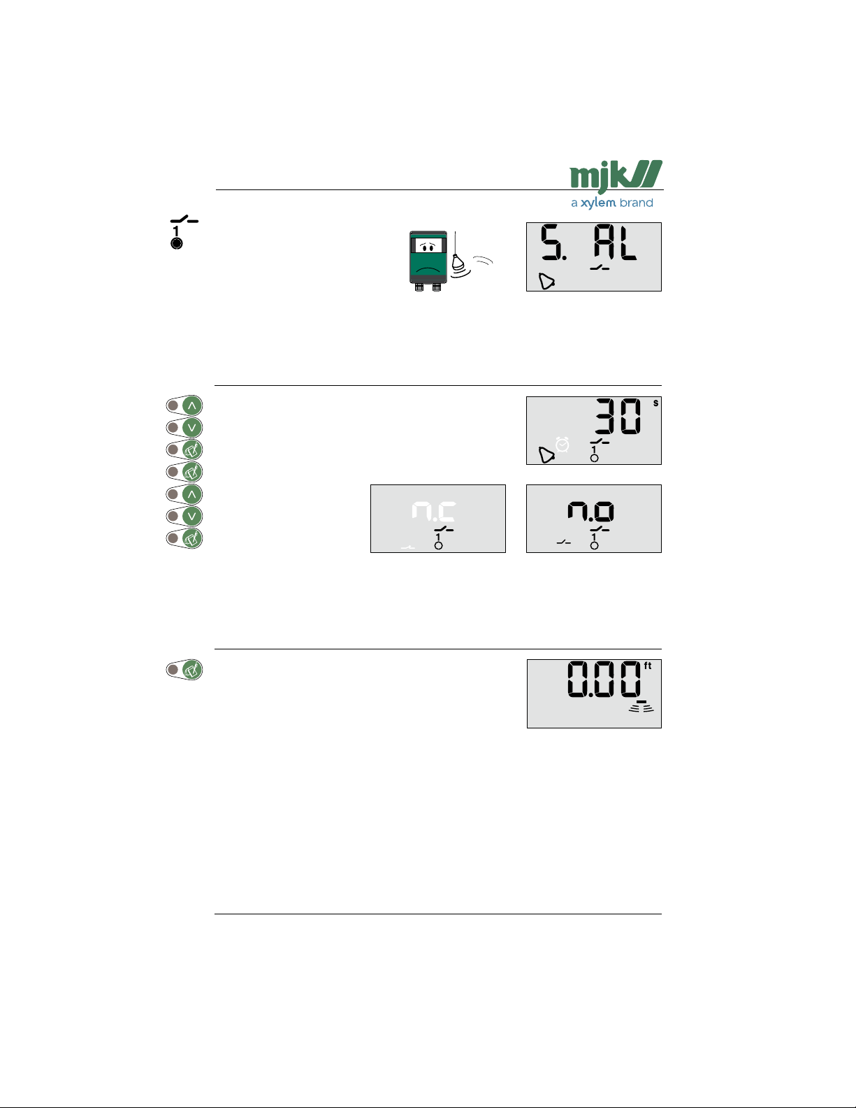
System alarm on relay 1
In this menu the time delay is set for the activation of relay 1 when a system error occurs
together with the reset position of the relay (normally open / normally closed):
Select the time delay.
Select relay mode.
('n.c' = normally closed,
'n.o' = normally open).
Note: If 'n.c' is selected, Shuttle® will also give alarm in case of power failure.
Shuttle® reverts to normal read-out.
US 2.10 Shuttle Manual 1510
24
SW 838023
Find Quality Products Online at: [email protected]
www.GlobalTestSupply.com
Page 25
Shuttle® - Ultrasonic Level Transmitter
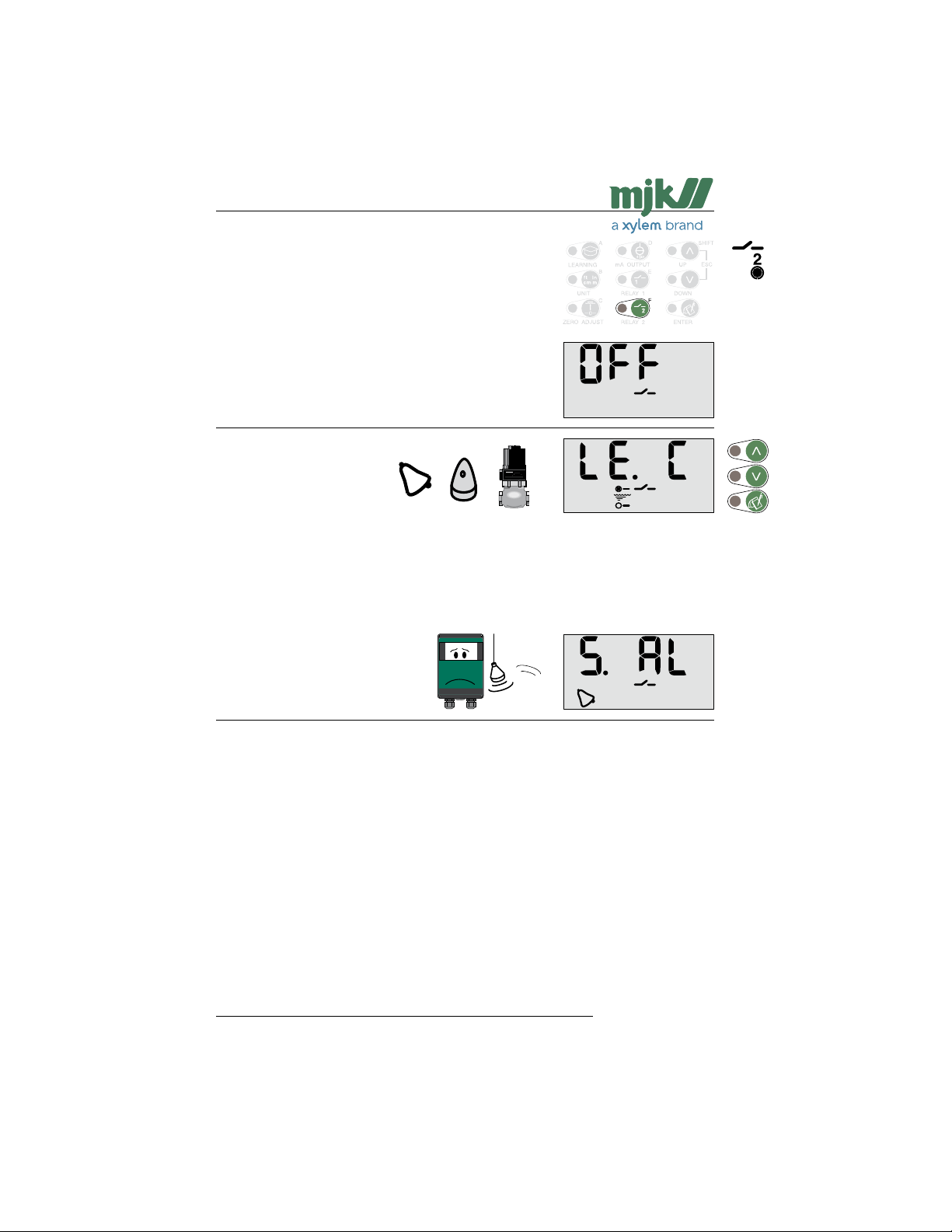
Selection of relay function for relay 2
Two functions are available:
- level control
- system alarm
Note: Both relays are already in use if pump control has
Select the desired function.
Level control:
Continue on the facing page.
System alarm:
See page 27.
been selected earlier.
US 2.10 Shuttle Manual 1510
Find Quality Products Online at: [email protected]
www.GlobalTestSupply.com
25
SW 838023
Page 26
Shuttle® - Ultrasonic Level Transmitter
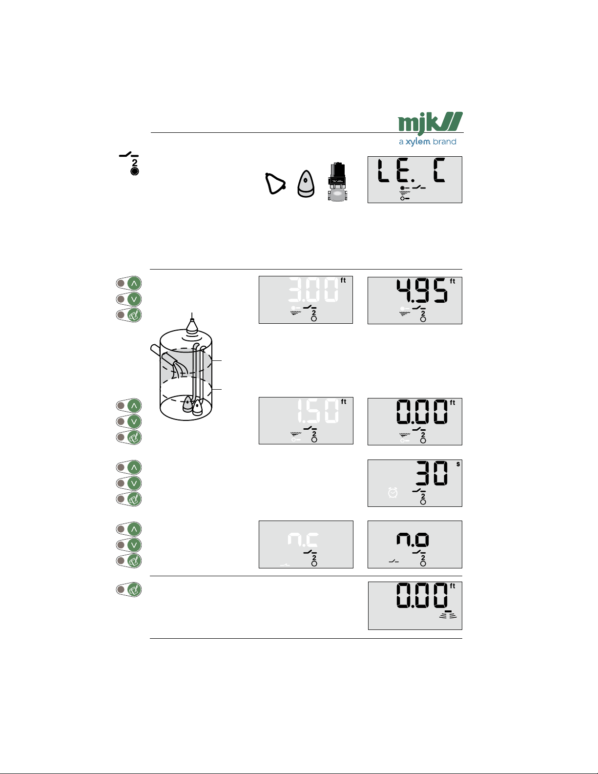
Level control with relay 2
In this menu the level for activation (set) of relay 1 is changed from 4.95 to 3.00 ft and deactivation (reset) of the relay output is changed from 0.00 to 1.50 ft.
Select the activation (set)
level with the arrow keys.
3.00 ft
1.50 ft
Select the deactivation
(reset) level with the arrow
keys.
Select the time delay.
Select relay mode.
('n.c' = normally closed,
'n.o' = normally open).
Shuttle® reverts to normal read-out.
US 2.10 Shuttle Manual 1510
26
SW 838023
Find Quality Products Online at: [email protected]
www.GlobalTestSupply.com
Page 27
Shuttle® - Ultrasonic Level Transmitter
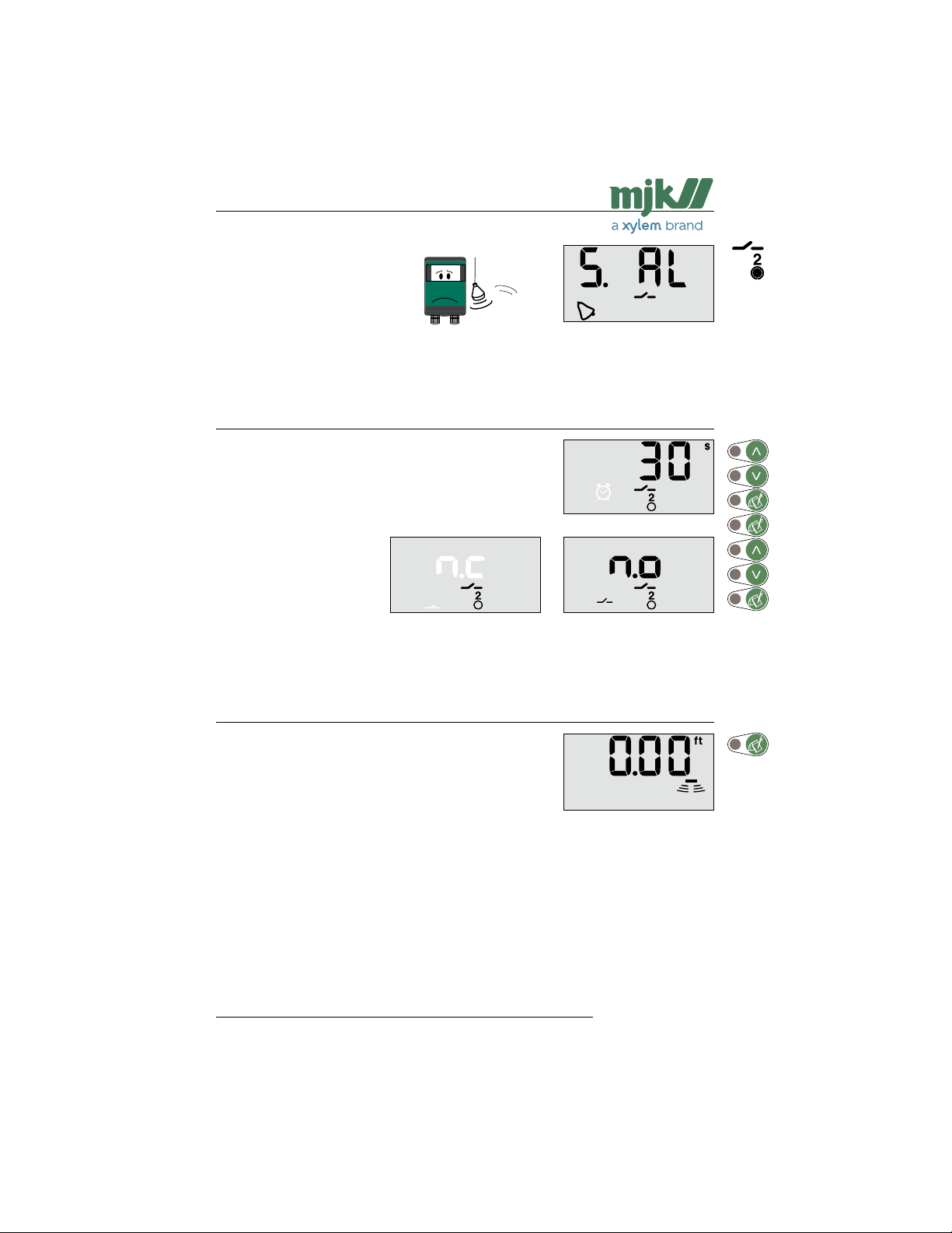
System alarm on relay 2
In this menu the time delay is set for the activation of relay 1 when a system error occurs
together with the reset position of the relay (normally open / normally closed):
Select the desired time delay.
Select relay mode.
('n.c' = normally closed,
'n.o' = normally open).
Note: If 'n.c' is selected, Shuttle® will also give alarm in case of power failure.
Shuttle® reverts to normal read-out.
US 2.10 Shuttle Manual 1510
27
SW 838023
Find Quality Products Online at: [email protected]
www.GlobalTestSupply.com
Page 28
Shuttle® - Ultrasonic Level Transmitter
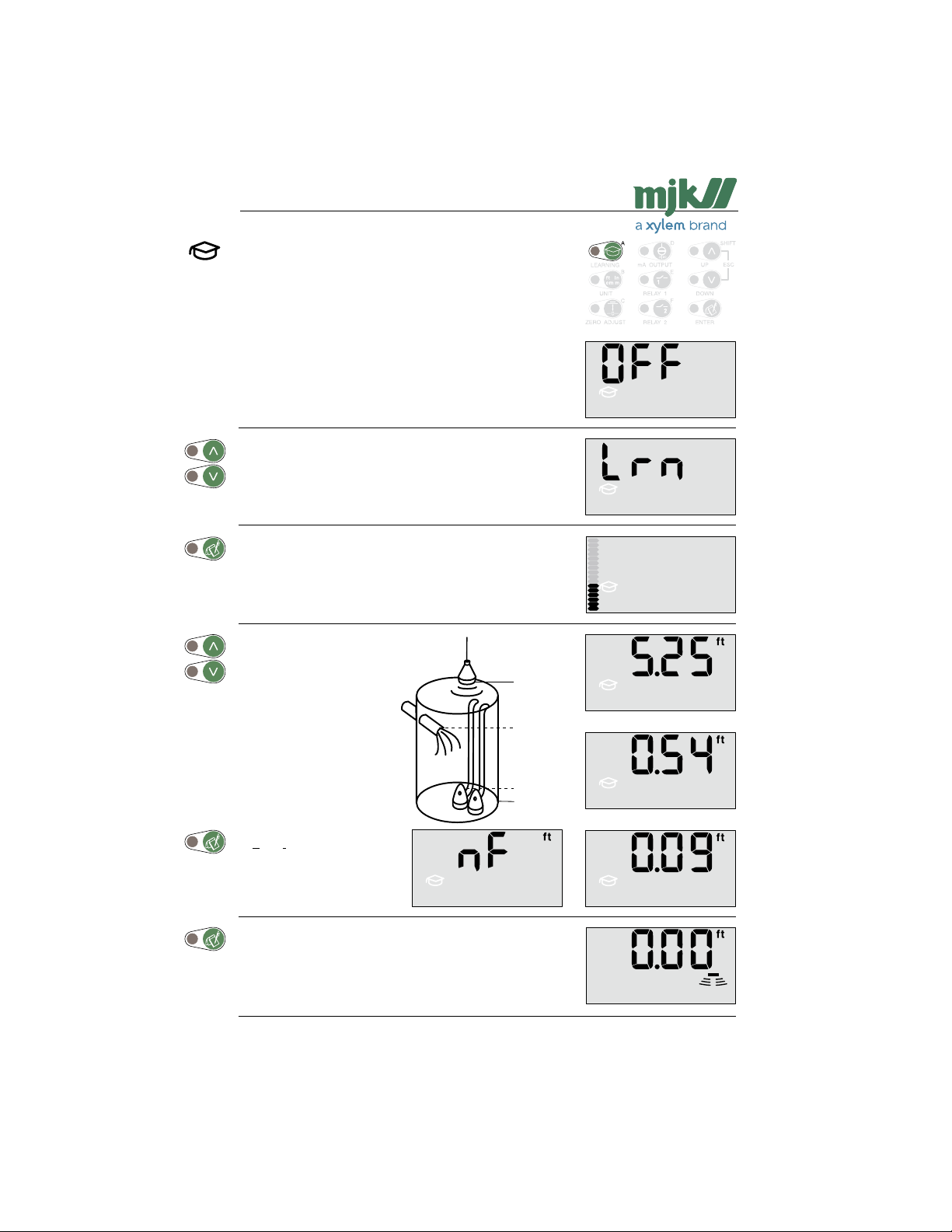
Start of the learning function
First time activation
With this function Shuttle® learns if there are any disturbances in the well or tank that could appear as a true echo.
Disturbances can result from inlet pipes, the pump installation, a slanted bottom, etc.
Shuttle® stores the levels of the false echoes, which will
practically eliminate the chance of locking on a false echo.
Shuttle® will look for a maximum of 15 echos.
Select the function with the arrow keys.
Note: Only this selection is available if the learning
Shuttle® starts to investigate the tank / well for disturbances.
The investigation is finished when all segments in the bar
graph are lit.
Note: According to the number of disturbing elements,
function settings have been erased earlier or the
function has never been activated before.
this process may take several minutes.
In this example, Shuttle®
has found two false echos
➀ (the inlet) and ➁ (from the
pump intallation) and also
the correct echo from the
bottom of the well / tank.
Select the level closest to
the correct level +/- 6 in (➂).
If none of the echoes are
from a true level measurement, but are all false
echoes (e.g. a slanted well
bottom), select 'nf'
(= none found).
Shuttle® now reverts to normal read-out.
Note: If 'nf'was selected as explained above, Shuttle®
will normally indicate system error until a varying
echo from a true level surface is detected.
US 2.10 Shuttle Manual 1510
6.00 ft
5.25 ft
0.54 ft
0.00 ft
28
➀
➁
➂
SW 838023
Find Quality Products Online at: [email protected]
www.GlobalTestSupply.com
Page 29
Shuttle® - Ultrasonic Level Transmitter
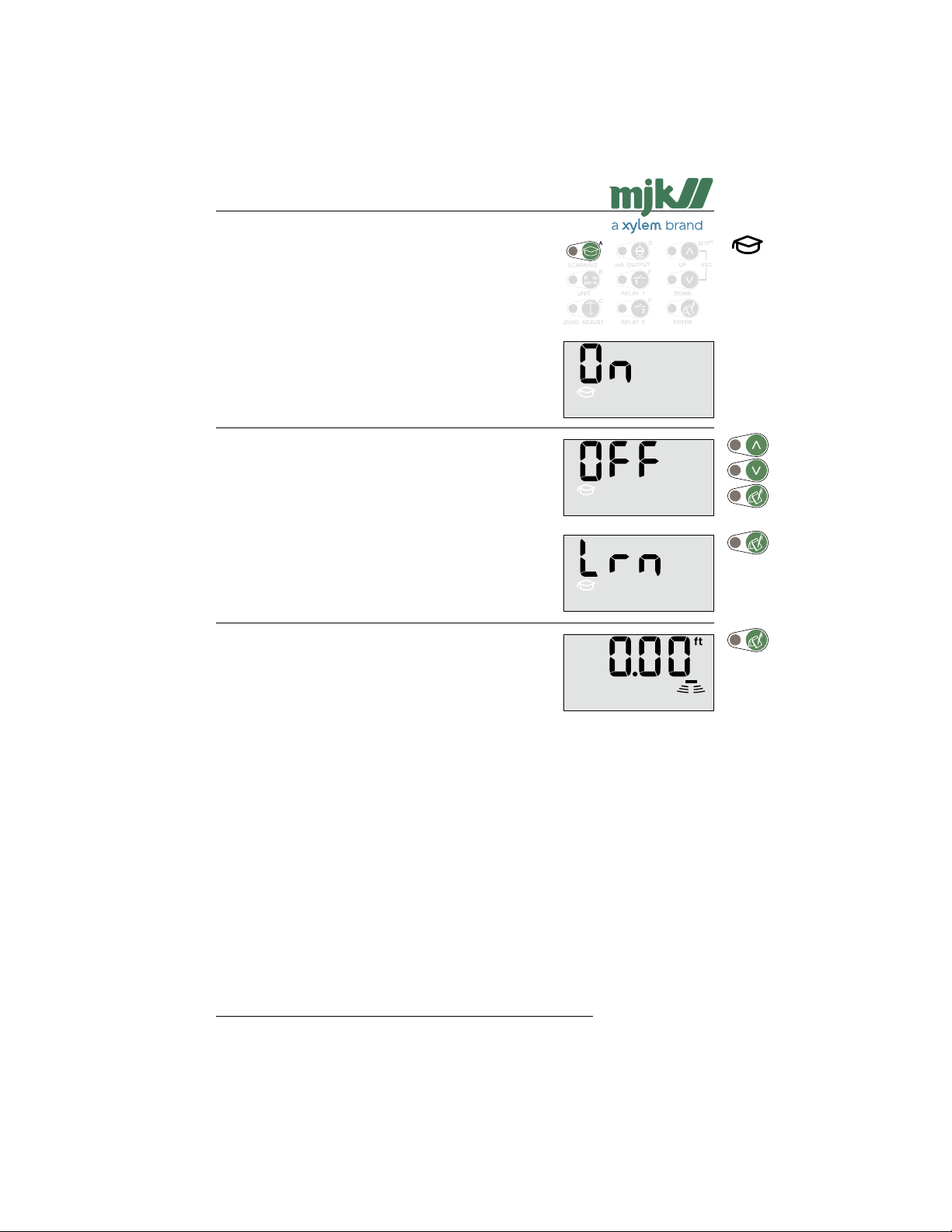
Activating the learning function
Activation / deactivation
This function activates or deactivates the learning function.
Select with the arrow keys.
If 'OFF' (deactivation) is selected, Shuttle® will still remem-
ber the levels of the false echos but will not take them into
consideration.
If 'ON' (activation) is selected, Shuttle® will take the false
echo levels into consideration.
If 'LRN' is selected, Shuttle® will start a new learning process.
Note: All levels found earlier will be erased.
If 'OFF' (or later 'ON') is selected, Shuttle® will revert to
normal read-out.
US 2.10 Shuttle Manual 1510
Find Quality Products Online at: [email protected]
www.GlobalTestSupply.com
29
SW 838023
Page 30
Shuttle® - Ultrasonic Level Transmitter
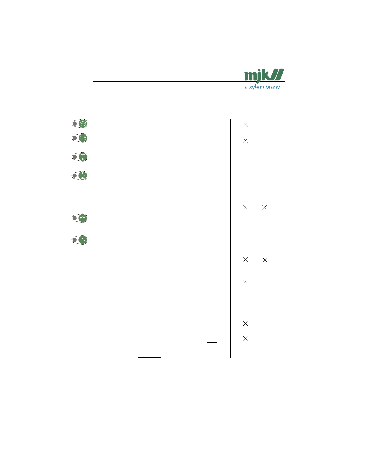
Settings
User settings
Learning function: ❒ Off ❒ On
Measuring unit: ❒ m ❒ in ❒ ft ❒ mm ❒ cm
Sensor / zero point distance:
Level read-out setting:
mA output: 4 mA =
20 mA =
Relay outputs: 1 2
Off: ❒ ❒
Pump control: ❒
Level control: ❒ ❒
System alarm: ❒ ❒
Start level:
Stop level:
Relay delay: sec.
NO/NC: ❒ (NC) ❒ (NC)
Factory settings
❒ Off
❒ ft
± 0
± 0
Zero point
4 in from sensor
1 2
❒ ❒
-
- -
- -
Zero point
4 in from sensor
30 sec. 30 sec.
❒ (NC) ❒ (NC)
bA
rA
rE
AP
S.Err
LE
Bar graph read-out: ❒ Off ❒ mA output ❒
Active measuring
range:
Response time: mm/s
Measuring method: ❒ 1 ❒ 2 ❒ 3
mA signal at
system error:
Calibration
of level read-out:
❒ Freeze ❒ Fixed signal, mA
read-out
User and factory settings
US 2.10 Shuttle Manual 1510
30
Level
❒ Off
From zero point to
14 in from sensor
100 mm/sec.
(4 in/sec)
❒ 1 (Fluid)
❒ Freeze
± 0
SW 838023
Find Quality Products Online at: [email protected]
www.GlobalTestSupply.com
Page 31

Shuttle® - Ultrasonic Level Transmitter
Possible settings
Learning function: On / Off
Measuring unit: m / in / ft / mm / cm
➀
Sensor / zero point distance: ± 99.99 ft
Level read-out setting: ➀ ± 99.99 ft
➁
mA output: ➀ ± 45 ft minus 4 in
➁ ± 45 ft
Start level: From (zero point + distance to sensor) to (max. range - zero point)
Stop level: From (zero point + distance to sensor) to (max. range - zero point)
Relay delay: 0 to 300 sec.
NO/NC: NO / NC
Bar graph read-out: Off / mA output / level read-out
Active
measuring range:
Response time: 0.1 to 300 mm/sec. (4/1000 to 11.8 in)
Measuring method 1 (Fluid) / 2 (Sludge and granulate) / 3 (Rapid level changes)
mA signal at
system error:
Calibration of level read-out: ± 5.9 in
US 2.10 Shuttle Manual 1510
Freeze / Fixed signal. (Fixed signal can be set from 3,5 to 20 mA)
4 in to max. range
31
SW 838023
Find Quality Products Online at: [email protected]
www.GlobalTestSupply.com
Page 32
Shuttle® - Ultrasonic Level Transmitter
Trouble shooting
General
Almost all system errors are due to the echo from the ultrasonic sensor being either too weak
or missing. This is normally caused by incorrect installation of the ultrasonic sensor, a faulty
ultrasonic sensor or by faults on the cable between the ultrasonic sensor and the Shuttle®
level meter. Other factors also have an influence on the ultrasonic level measurement. But
always check first that the ultrasonic sensor is installed correctly and is working properly. See
also the fault finding table on the facing page.
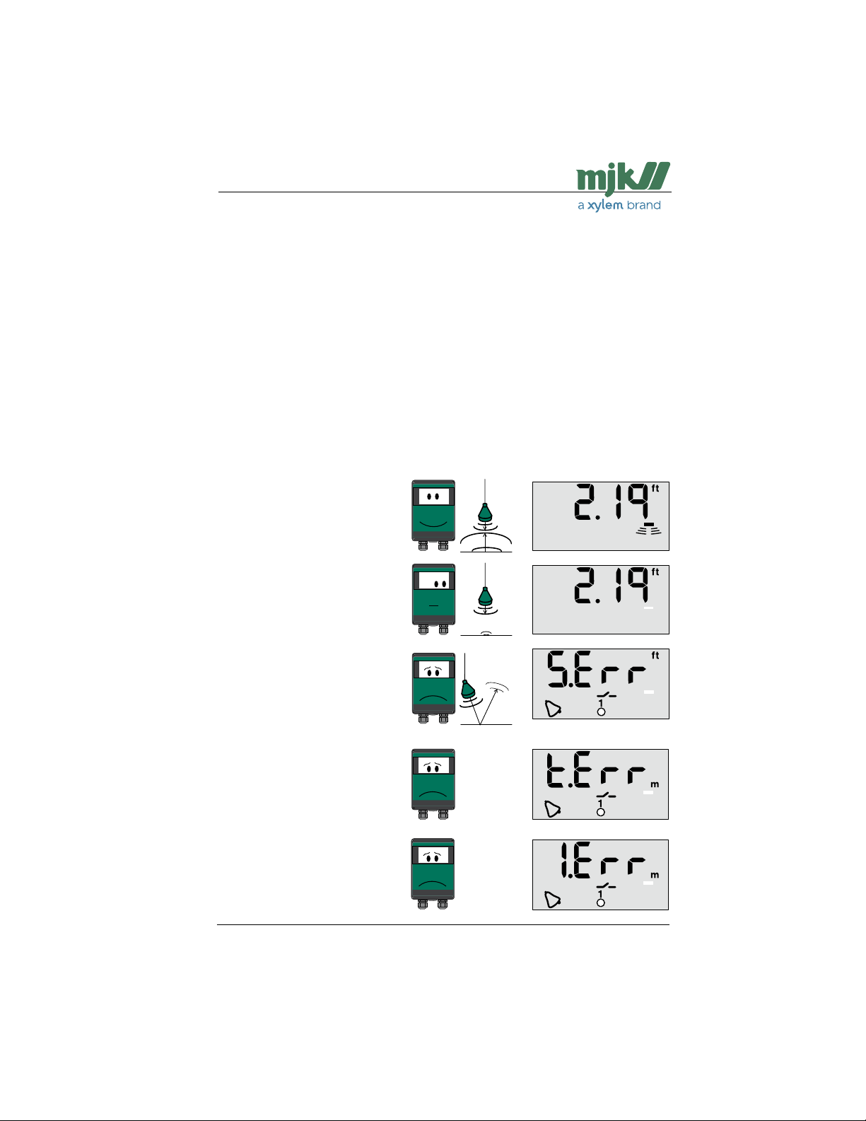
Indications on system errors
First, Shuttle® will indicate that the echo is too weak or missing. After 5 minutes Shuttle® displays 'S.Err', and if one of the relays is set to be activated on a system error, the relay will be
activated after the delay time. At the same time the signal from the mA output will be either
locked on the last known value or provide a preset signal value (3.5 - 20.5 mA). Other valid
error types are temperature errors, internal stack errors and EE-PROM errors (see below).
If the problem disappears, Shuttle® will change back to normal read-out. At the same moment, the relay output set as alarm output will switch back to its normal position and the mA
output will provide a normal signal.
Normal read-out
Shuttle® receives an echo
that has sufficient strength
for a safe and reliable level
measurement.
Too weak or missing echo
The received echo is too
weak for Shuttle® to perform a safe and reliable level
measurement.
System (sensor) error
If echo is still weak after 5
minutes, Shuttle® enters
system error mode and
sends an alarm. Also, relays
configured for pump control
will be deactivated.
Temperature error
Contack an MJK service
representative, if a temperature error appers.
Internal stack error
Contack an MJK service
representative, if an internal
stack error appers.
US 2.10 Shuttle Manual 1510
Find Quality Products Online at: [email protected]
www.GlobalTestSupply.com
32
SW 838023
Page 33
Shuttle® - Ultrasonic Level Transmitter
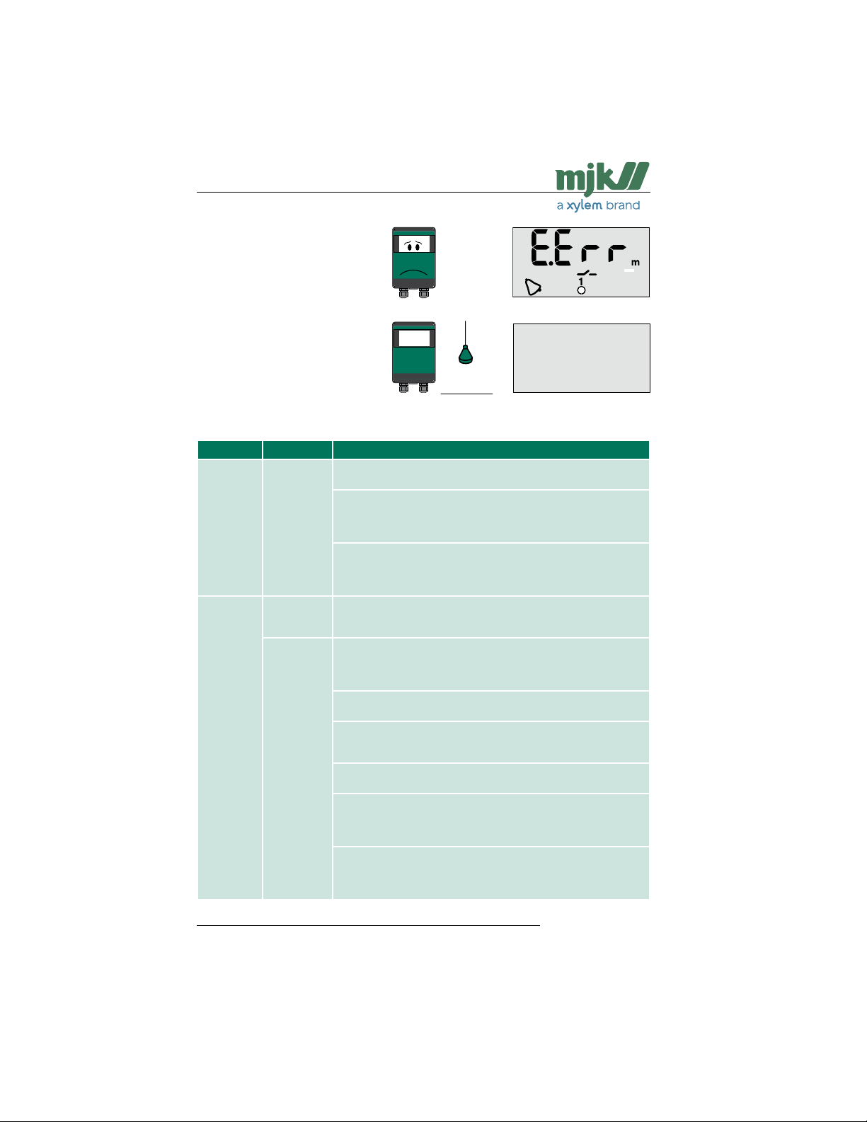
EE-PROM error
Contack an MJK service
representative, if an EEPROM error appers.
Power failure
If one of the relay outputs is
set to NC (normally closed),
an external alarm is immediately sent out at power
failure.
Trouble shooting table
Problem Cause Remedies
The display
is not lit
Shuttle®
indicates
system error
Power supply Wire mounting Is min. 0.4 in (13/32 in) of the insulation removed and
Liquid
surface
Ultrasonic
sensor
firmly mounted?
AC supply Is correct live voltage present between terminals L and
N?
Is the right-hand fuse (40 mA@230 VAC, 100 mA@115
VAC) intact? Exchange if necessary.
DC supply Is 10 - 30 VAC present between terminals 10 and 12,
and is the polarity correct?
Is the left-hand fuse (200 mA) intact? Exchange if
necessary.
Measuring Is the liquid surface foamy? Try changing the setting
method for measuring method from 'AP 1' to 'AP 2'.
(Shift + D)
Wire mounting Is a minimum of 0.4 in (13/32 in) of the insulation
removed and the wires firmly mounted?
Are the wires connected to the correct terminals? See
the connection diagram.
Cable Are there water in the connections, and are the
extensions extensions made correctly?
Condition Is the black part of the sensor miscoloured or
cracked? Miscolouring indicates that the sensor is not
suited for the environment on the installation site.
Function Is the sensor transmitting clicking sounds? If not, the
sensor is faulty.
Sensor Is the sensor mounted ABSOLUTELY VERTICAL?
mounting It is extremely important that the sensor is firmly
mounted in a vertical position. See the section
'Mechanical mounting of sensor'.
Measuring Is the sensor mounted so that the measuring distance
distance is less than the deadband and more that the max.
range? The max./min. measuring range must not be
exceeded.
US 2.10 Shuttle Manual 1510
Find Quality Products Online at: [email protected]
www.GlobalTestSupply.com
33
SW 838023
Page 34
Shuttle® - Ultrasonic Level Transmitter
Shuttle®
indicates
system error
constantly
Level readout is not
changing
Level readout is wrong
Level
read-out is
unstable
®
Shuttle
Ultrasonic
sensor
Ultrasonic
sensor
®
Shuttle
Ultrasonic
sensor
®
Shuttle
Setting Is the setting of the active measuring range (Shift + B)
correct? The active measuring range must not be set
lower than the max. possible level.
Sensor Is the sensor mounted ABSOLUTELY VERTICAL?
mounting It is extremely important that the sensor is firmly
mounted in a vertical position. See the section
'Mechanical mounting of sensor'.
Installation Are there for example bit, fatty accumulations or other
site objects disturbing the ultrasonic signal?
Setting Has the learning function been activated? If the
learning function has not been activated, Shuttle® may
lock on a false echo.
Sensor Is the sensor mounted ABSOLUTELY VERTICAL?
mounting It is extremely important that the sensor is firmly
mounted in a vertical position. See the section
'Mechanical mounting of sensor'.
Cable Is the sensor cable extended with a not-approved
cable type and/or extended beyond 300 ft?
Installation Does the ultrasonic sensor have the same temperature
as the ambient air? Deviations will produce measuring
errors!
Setting Shuttle® level readout may need adjustment (zero point adjustment)
Sensor Is the sensor mounted ABSOLUTELY VERTICAL?
mounting It is extremely important that the sensor is firmly
mounted in a vertical position. See the section
'Mechanical mounting of sensor'.
Is the sensor mounted firmly? The sensor should be
mounted on a suitable bracket.
Installation Turbulence on the surface.
site Objects on the surface that disturb the measurement.
Strong winds can bend off the echo, so it misses the
ultrasonic sensor.
Setting Response time (Shift + C) is set too low.
US 2.10 Shuttle Manual 1510
Find Quality Products Online at: [email protected]
www.GlobalTestSupply.com
34
SW 838023
Page 35
Shuttle® - Ultrasonic Level Transmitter
Ex Instructions
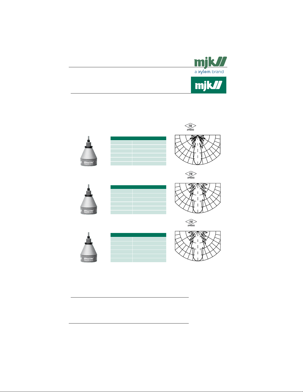
Quick Installation Guide - FM-approved MJK Ultrasonic Sensors
MJK Ultrasonic Sensor Installation
MJK Automation A/S offers a variety of FM-approved ultrasonic sensors for the MJK Shuttle® Level Converter, the
MJK 704 Pump Controller and the MJK 713 Open Channel Flow Converter.
This quick guide solely covers mounting and installation of the FM-approved MJK Shuttle sensors in hazardous
locations.
Shuttle® Ultrasonic Sensor Type 200630 - Extended Range w/ 39 ft. cable
•
Shuttle® Ultrasonic Sensor Type 200631 - Extended Range w/ 150 ft. cable
•
Shuttle®Ultrasonic Sensor: 200630 (200631)
Range: 75 ft. (fluids), 30 ft. (solids)
Frequency: 30 kHz
Spread: 6°
Deadband: 32"
Temperature: - 5 °F to + 150 °F
•
Shuttle® Ultrasonic Sensor Type 200640 - Standard Range w/ 39 ft. cable
•
Shuttle® Ultrasonic Sensor Type 200641 - Standard Range w/ 150 ft. cable
•
Shuttle® Ultrasonic Sensor Type 200650 - Short Range w/ 39 ft. cable
•
Shuttle® Ultrasonic Sensor Type 200651 - Short Range w/ 150 ft. cable
Materials: PBF/ceramic
Shuttle®Ultrasonic Sensor: 200640 (200641)
Range: 35 ft. (fluids), 15 ft. (solids)
Frequency: 40 kHz
Spread: 7°
Deadband: 14"
Temperature: - 5 °F to + 150 °F
Materials: PBF/ceramic
Shuttle®Ultrasonic Sensor: 200650 (200651)
Range: 10 ft. (fluids), 4 ft. (solids)
Frequency: 75 kHz
Spread: 7°
Deadband: 14"
Temperature: - 5 °F to + 150 °F
Materials: PBF/ceramic
-40
-30
-20
-10
-40
-30
-20
-10dB
-40
-30
-20
-10dB
dB
0
0
0
3030
3030
3030
9090
6060
9090
6060
9090
6060
See comprehensive information about the MJK Shuttle® Level Converter, the MJK 704 Pump Controller and the
MJK 713 Open Channel Flow Converter in their respective data sheets, installation and user manuals.
Sensor Installation in Class I, II and III, Div. 1 & 2, A, B, C, D, E, F, G Hazardous Locations
UltraSonic Sensor Installation DWG 5049 070327
US 2.10 Shuttle Manual 1510
Find Quality Products Online at: [email protected]
www.GlobalTestSupply.com
Page 1 of 2
35
SW 838023
Page 36
Shuttle® - Ultrasonic Level Transmitter
Quick Installation Guide - FM-approved MJK Ultrasonic Sensors
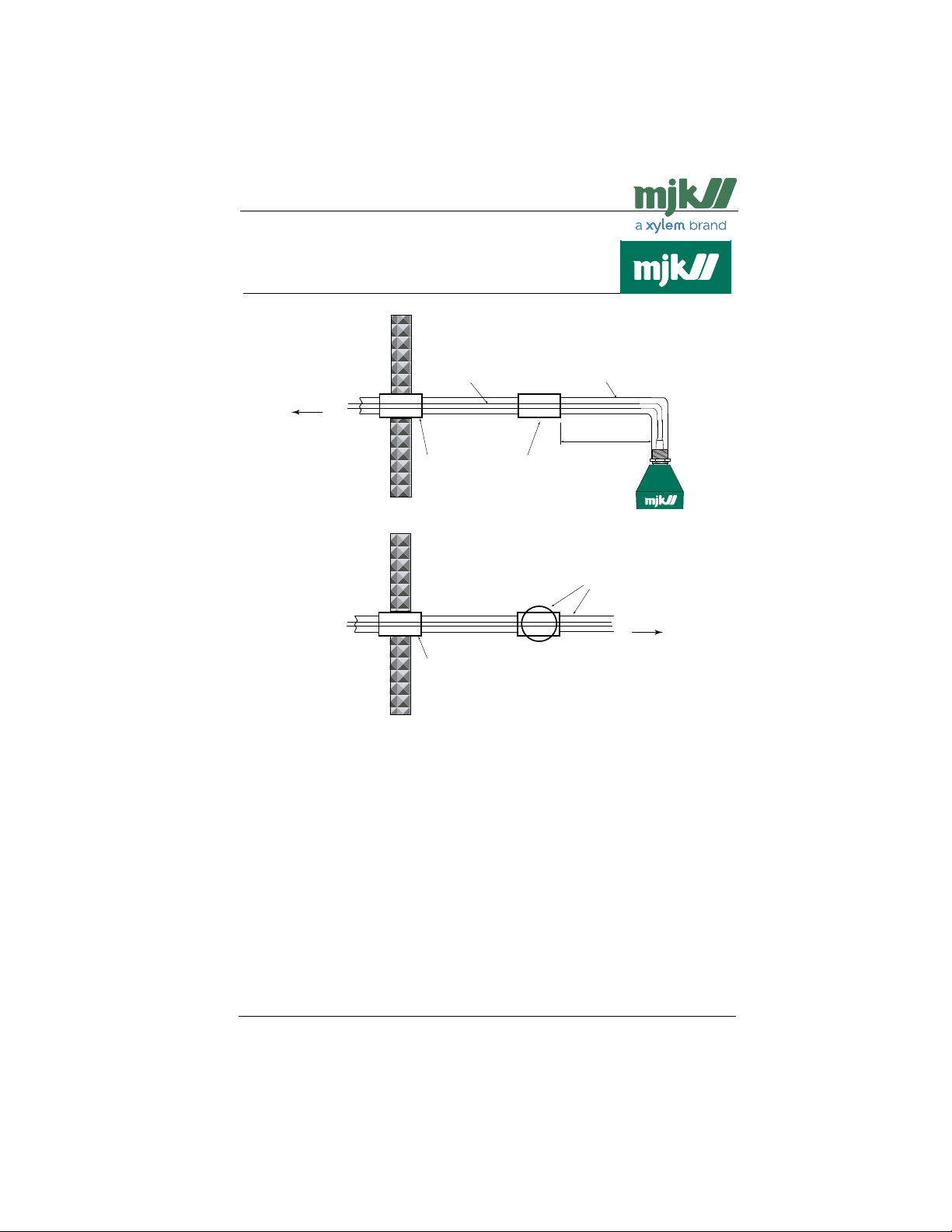
Class I, II and III, Div. 1 & 2,
A, B, C, D, E, F, G
hazardous location
User supplied conduits
and materials, see notes.
Max. 18 inches
User supplied conduit and
connection box, see notes.
To MJK ultrasonic
sensor
To MJK transmitter
Optional MJK
extension cable
p/n 690010
Integral sensor cable,
see notes.
Required for Class I, II and III,
Div. 1 & 2 locations sealing fittings,
sealing cement and fiber kit.
See notes
Class I, II and III, Div. 1 & 2,
A, B, C, D, E, F, G
hazardous location
Required for Class I, II and III,
Div. 1 & 2 locations sealing fittings,
sealing cement and fiber kit.
See notes
Notes for customer supplied materials and services
Cables, fittings and conduits must be installed by the customer in accordance with NEC 501-4, 502-4 or 503-3.
1.
In Class I, II and III, Div. 1 & 2, A, B, C, D, E, F, G hazardous (classified) locations all seal fittigs, sealing com-
2.
pounds, connections boxes, conduits, fittings, etc. must be certified and approved for use in the above mentioned locations.
Minimum thread engagement between all threaded joints must be a maximum of 5 full threads.
3.
Interconnecting cable conduits and fittings must be grounded to a proper electrical ground. Bonding between all
4.
conduit connections must be provided and installed by the customer as part of installation.
The sensors are provided with an integral cable. An extension cable must MJK cable, part no. 690010.
5.
The cable must be run in accordance with NEC (ANSI/NFPA 70), CEC pt. I and/or applicable local code require-
6.
ments.
This installation guide is under MJK control, and modifications are not allowed without consent from the certifying
7.
authority.
US 2.10 Shuttle Manual 1510
Find Quality Products Online at: [email protected]
www.GlobalTestSupply.com
36
SW 838023
Page 37
Shuttle® - Ultrasonic Level Transmitter
A Tecnical specifications
Shuttle® Level Transmitter
Measuring range 0 - 75 ft
Span From 0 - 4" to 0 - 75 ft
Power supply 115 / 230 V AC, 10 - 30 V DC
Consumption 2 W
Temperature - 5 to + 150 °F
Input From ultrasonic sensor
Accuracy
Outputs Analogue: 1 pc. 4 - 20 mA, max. 500 Ω loop impedance.
Display LCD with 4 digits and symbols
Operation Function keys behind the front cover
Enclosure NEMA 4X
CE approvals EN 50081-1, EN 50082-1
➀ The accuracy is stated for the selected measuring range with the sensor mounted 14 in above highest possible level
and with subsequent calibration of level readout as explained on page 52 and when measuring on an even surface
without foam build-up or other disturbing objects.
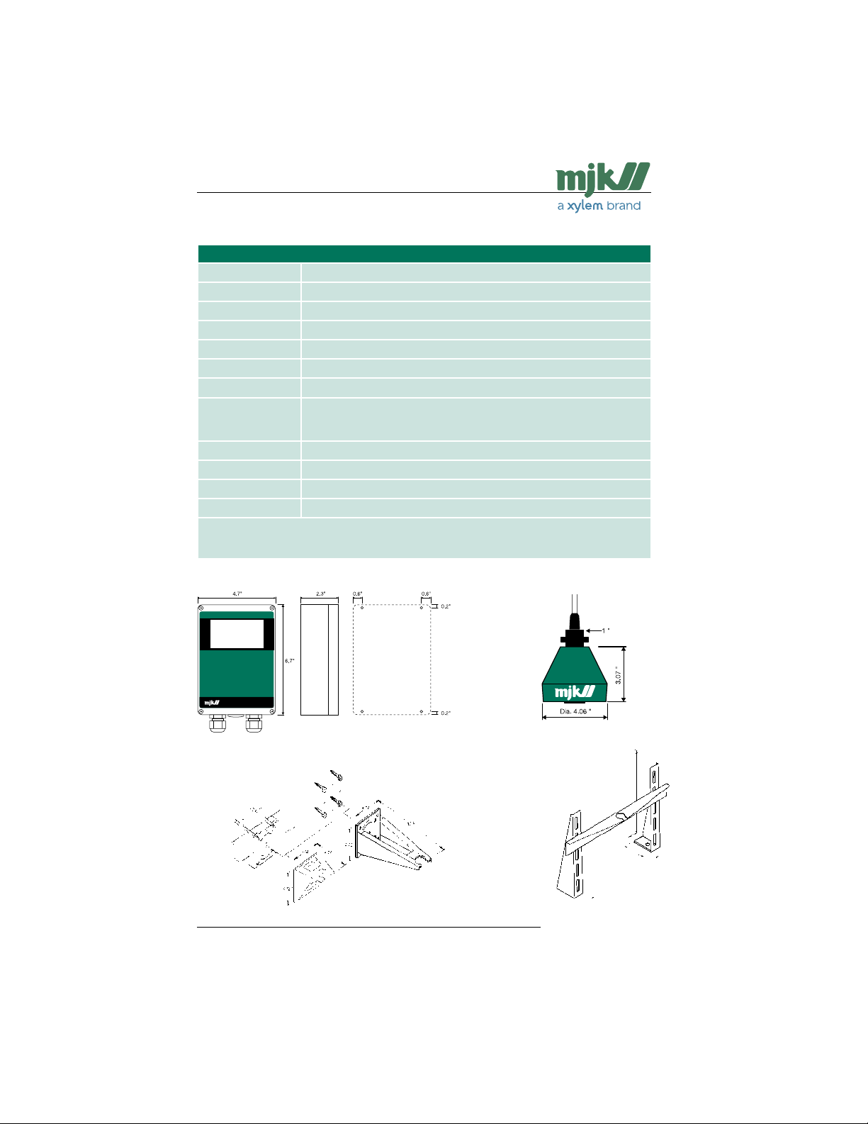
Dimensions
Better than ± 0,2% ➀
Digital: 2 pcs. relays with connect or disconnect function (NO/NC).
Max. 50 V DC, 1 A ohmic / 50 V AC, 50 VA.
Shuttle® Level Transmitter
Universal bracket
Short sensor bracket
US 2.10 Shuttle Manual 1510
Standard sensor bracket
37
ISO
Shuttle® Ultrasonic Sensor
19.7 in
2 in
4.5 in
26.6 / 37.4 in
Sensor bracket for channel or flume
SW 838023
Find Quality Products Online at: [email protected]
www.GlobalTestSupply.com
Page 38
Shuttle® - Ultrasonic Level Transmitter
9090
6060
3030
0
-40
-30
-20
-10
dB
Shuttle® Ultrasonic Sensors
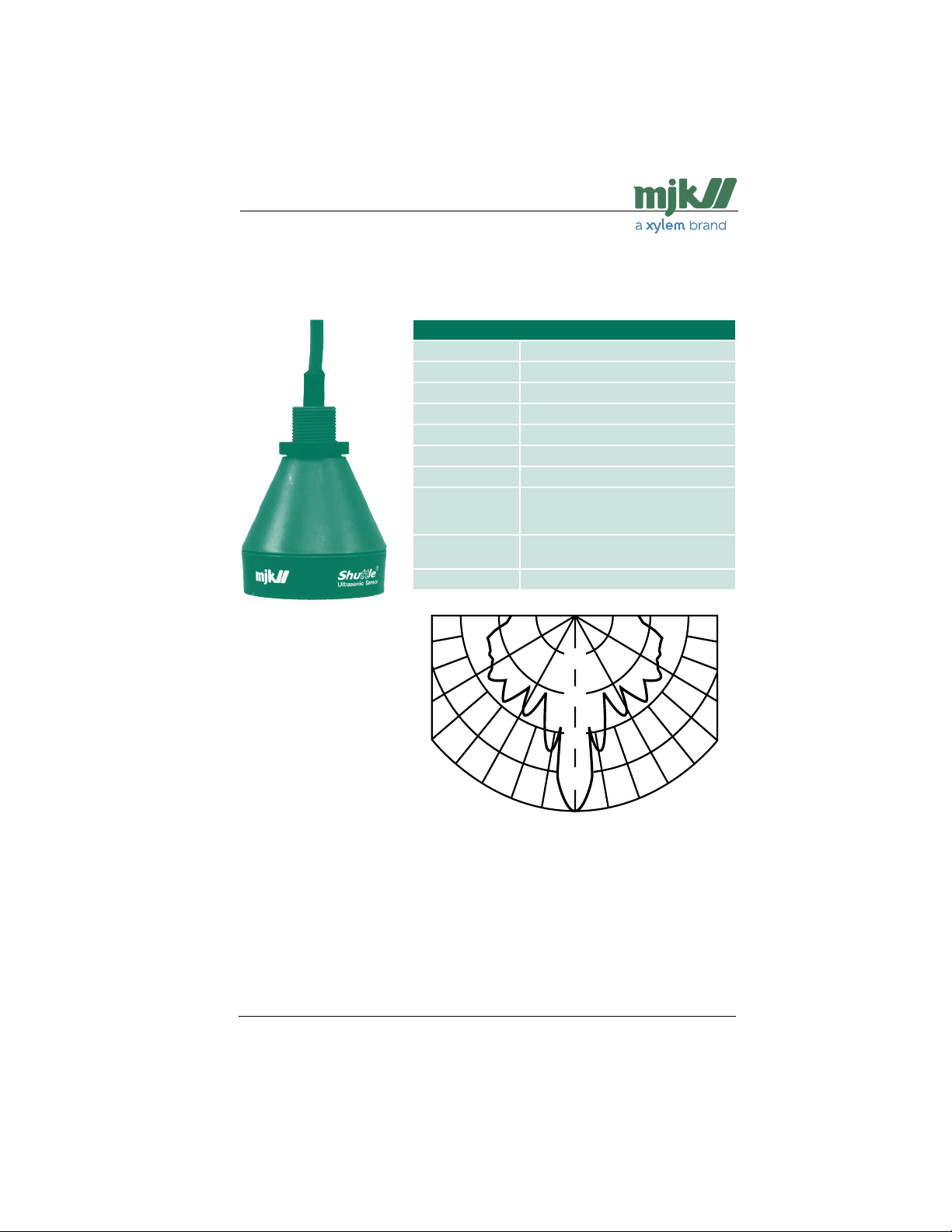
Standard Range Version
Shuttle® Ultrasonic Sensor Type 200570
Measuring range 45 ft (liquids), 18 ft (solids)
Frequency 30 KHz
Spread 3 °
Dead band 14 in
Sensitivity See figure below
Temperature - 5 to + 150 °F
Materials PP (green), POM (black)
Cable Shielded, insuated with oil resistant PVC,
Enclosure NEMA 6P, water-proof, withstands sub-
CE approvals EN 50081-1, EN 50082-1
length 39 ft
(Max. 300 ft with 690010 cable)
merging, max. 1 bar
US 2.10 Shuttle Manual 1510
38
SW 838023
Find Quality Products Online at: [email protected]
www.GlobalTestSupply.com
Page 39
Shuttle® - Ultrasonic Level Transmitter
90
60
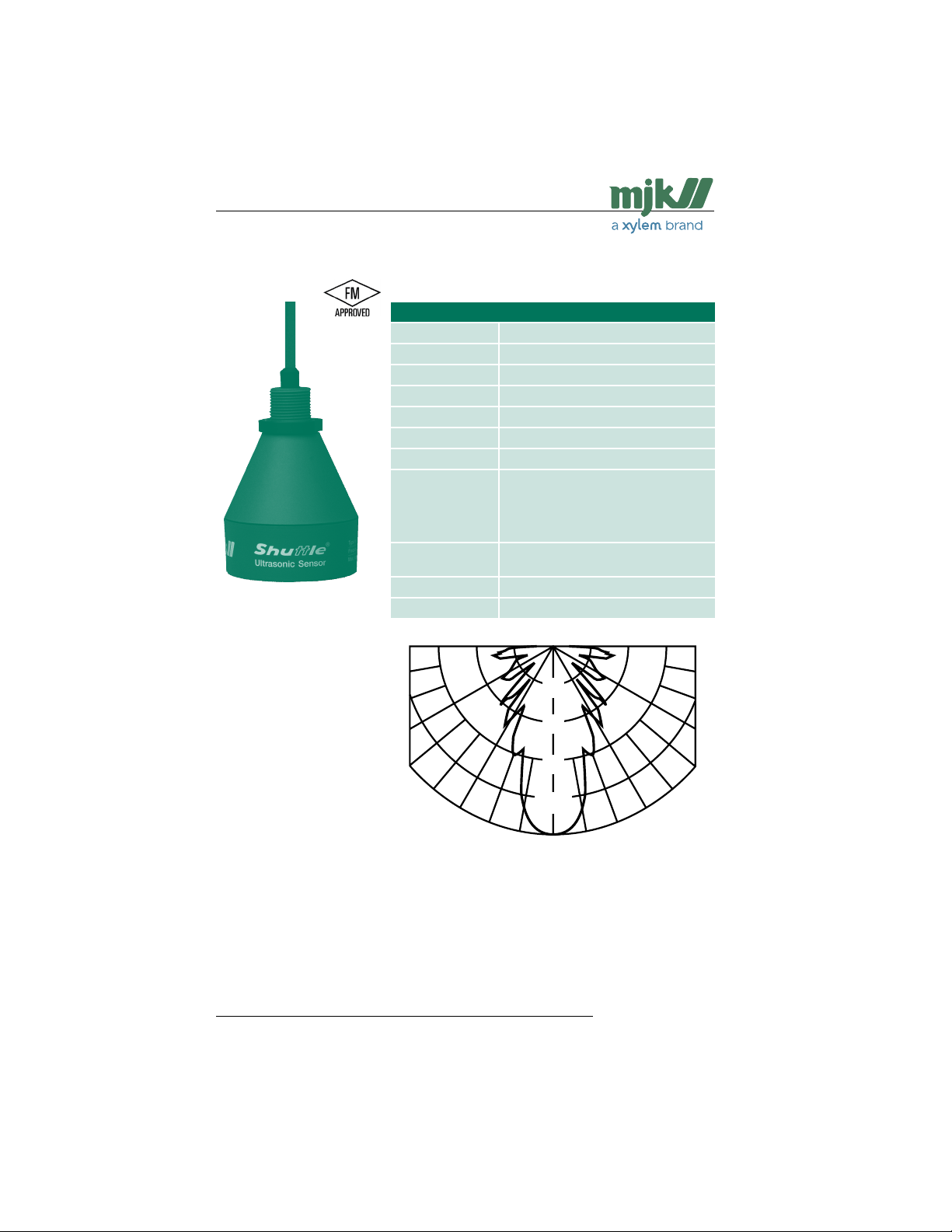
Standard Range Version/FM Approved
Shuttle® Ultrasonic Sensor Types 200640 / 200641
Measuring range 35 ft (liquids), 15 ft (solids)
Frequency 40 KHz
Spread 7 °
Dead band 14 in
Sensitivity See figure below
Temperature - 5 to + 150 °F
Materials VALOX
Cable 200640:
Cable 200641:
Enclosure NEMA 6P, water-proof, withstands sub-
CE approvals EN 50081-1, EN 50082-1
Ex approvals FM Class 1, Div. 1, Group A-G
90
Shielded, insuated with oil resistant PVC,
length 39 ft.
Shielded, insuated with oil resistant PVC,
length 150 ft
(Max. 300 ft with 690010 cable)
merging, max. 1 bar
US 2.10 Shuttle Manual 1510
60
39
-40
-30
-20
-10dB
3030
0
SW 838023
Find Quality Products Online at: [email protected]
www.GlobalTestSupply.com
Page 40
Shuttle® - Ultrasonic Level Transmitter
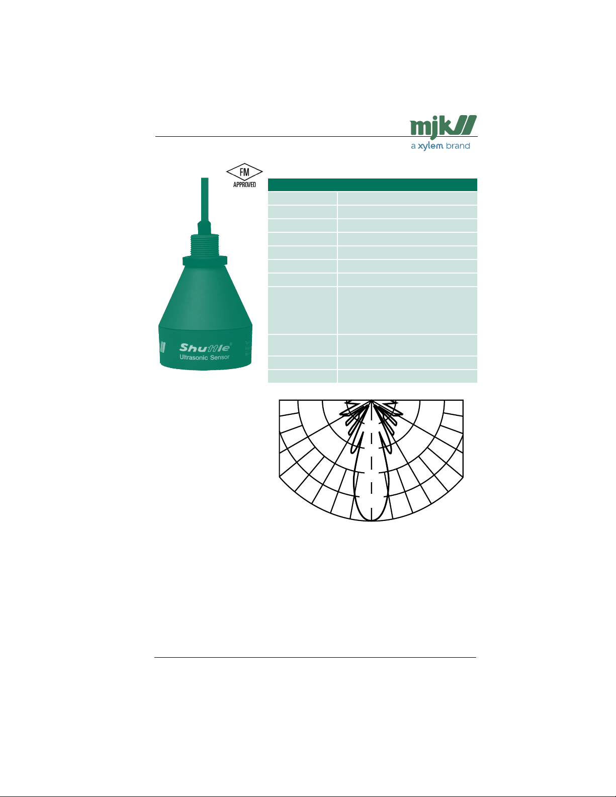
Extended Range Version
Shuttle® Ultrasonic Sensor Types 200630 / 200631
Measuring range 75 ft (liquids), 30 ft (solids)
Frequency 30 KHz
Spread 6 °
Dead band 32 in
Sensitivity See figure below
Temperature - 5 to + 150 °F
Materials VALOX
Cable 200630:
Cable 200631:
Enclosure NEMA 6P, water-proof, withstands sub-
CE approvals EN 50081-1, EN 50082-1
Ex approvals FM Class 1, Div. 1, Group A-G
Shielded, insuated with oil resistant PVC,
length 39 ft.
Shielded, insuated with oil resistant PVC,
length 150 ft
(Max. 300 m with 690010 cable)
merging, max. 1 bar
9090
US 2.10 Shuttle Manual 1510
40
-10
-40
-30
-20
6060
dB
3030
0
SW 838023
Find Quality Products Online at: [email protected]
www.GlobalTestSupply.com
Page 41
Shuttle® - Ultrasonic Level Transmitter
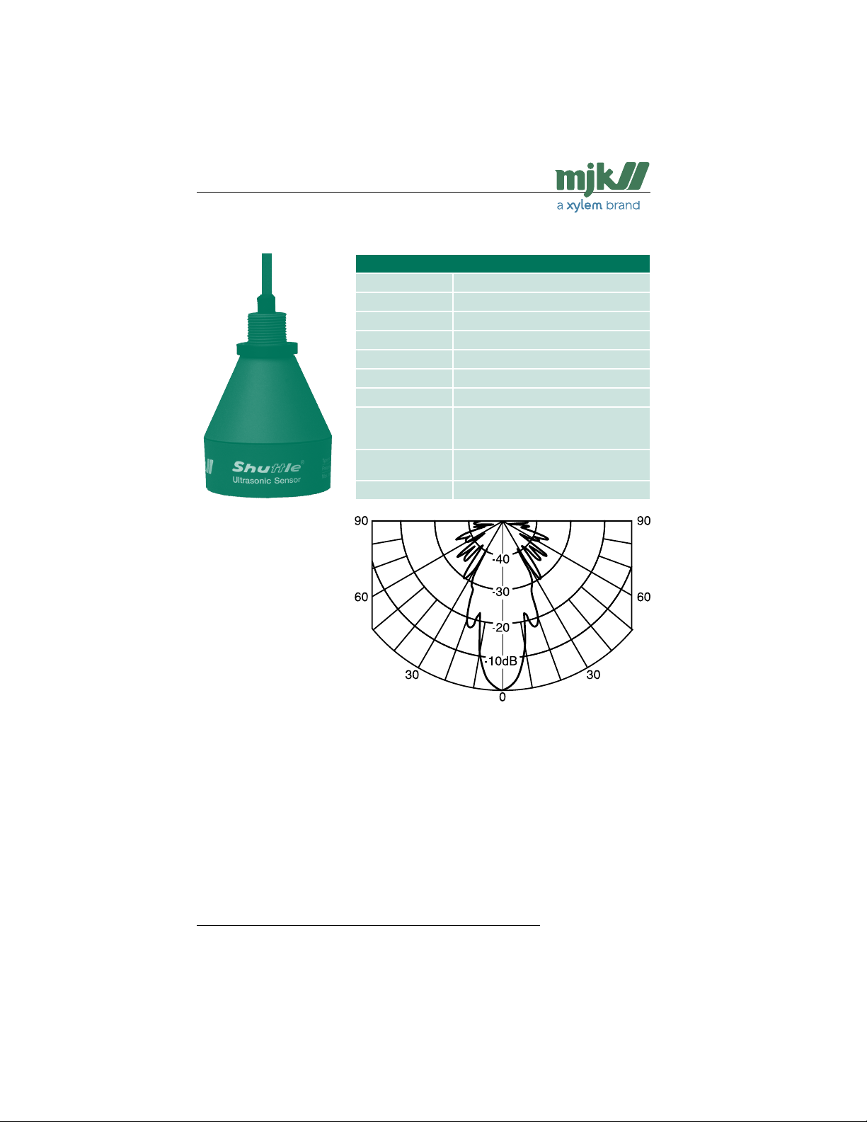
Chemical Resistant Version
Shuttle® Ultrasonic Sensor Type 200660
Measuring range 30 ft (liquids), 15 ft (solids)
Frequency 50 KHz
Spread 6 °
Dead band 14 in
Sensitivity See figure below
Temperature - 5 to + 150 °F
Materials PP, PVDF
Cable Shielded, insuated with oil resistant PVC,
Enclosure NEMA 6P, water-proof, withstands sub-
CE approvals EN 50081-1, EN 50082-1
length 39 ft
(Max. 300 ft with 690010 cable)
merging, max. 1 bar
US 2.10 Shuttle Manual 1510
Find Quality Products Online at: [email protected]
www.GlobalTestSupply.com
41
SW 838023
Page 42
Shuttle® - Ultrasonic Level Transmitter
B Changing supply voltage
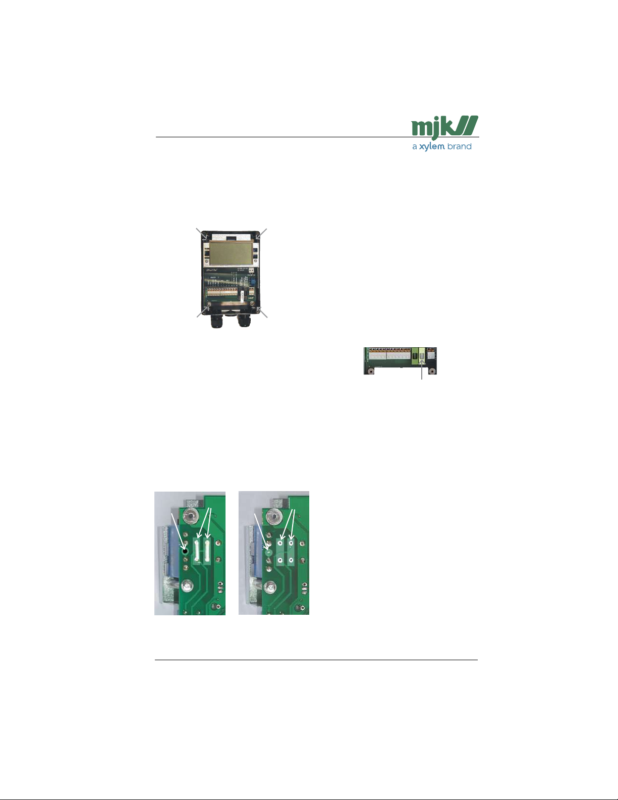
1: Remove the lid, detach the wires from
the terminal blocks and remove the four
screws that hold the electronics in the
cabinet.
2: Take out the electronics and turn it
around.
Look at the upper left corner and look
if two soldering brackets (pos. B) are
mounted and if the conducting branch
(pos. A) is broken or not.
- two soldering bridges are mounted
(pos. B) and the conducting branch
(pos. A) is broken: Shuttle® is intended
for 115 V AC.
- no soldering bracket is mounted (pos
B) and the conducting branch (pos. A)
is not broken: Shuttle® is intended for
230 V AC.
Conversion from 115 to 230 V AC
Remove the two soldering brackets
between the soldering points (pos. B).
Close the conducting branch (pos A).
Turn around the electronics and ex-
change the rightmost fuse to a 40 mA
fuse.
Conversion from 230 to 115 V AC
Mount two soldering brackets between
the soldering points (pos. B) and break
the conducting branch or drill out the
soldering point (pos A).
Turn around the electronics and ex-
change the rightmost fuse to a 100 mA
fuse.
The rightmost fuse should be rated
100 mA @ 115 VAC or 40 mA @ 230 VAC.
3: Mount the electronics in the cabinet,
mount the wires in the terminal blocks
and mount the lid.
A A
115 V AC 230 V AC
US 2.10 Shuttle Manual 1510
Find Quality Products Online at: [email protected]
B
www.GlobalTestSupply.com
B
42
SW 838023
Page 43
Shuttle® - Ultrasonic Level Transmitter
C Sensor mounting considerations
General
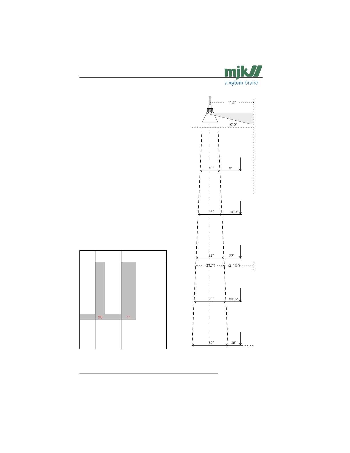
The ultrasonic sensor is characterized by a
very narrow spread of the ultrasonic signal
(3 ° - 7 ° depending on the type of sensor),
which makes it possible to use the ultrasonic sensor under very tight conditions, i.e. in
narrow wells or tanks. 80 % of the ultrasonic
signal is concentrated within this area, which
will give a sufficient echo in the far most
cases.
It is required though, that the ultrasonic
signal is not being muffled or disturbed by
gratings, pipes, cables etc., and that the
ultrasonic sensor is not mounted so the
ultrasonic signal is sent too close to a tank
wall or well wall.
The spread of the ultrasonic signal
The illutration to the left shows the spread
of the ultrasonic sensor in conjunction with
the measuring distance, the ultrasonic signal
spread will be 23 in at a measuring distance
of 30 ft.
Acordingly, as the measuring distance increases, the distance from the center line to
a smooth wall should also be increased.
Distance
Spread (inch) Min. dist. from wall (inch)
(feet)
3° 6° 7° at 3° at 6° at 7°
6 8 8 3 4 4
3
8 11 13 4 6 6
6
10 15 17 5 8 8
9
11 19 21 6 9 11
12
13 23 26 7 11 13
15
15 26 30 8 13 15
18
17 30 34 8 15 17
21
19 34 39 9 17 19
24
21 37 43 10 19 21
27
2
3 41 47 11 21 24
30
24 45 52 12 22 26
33
26 49 56 13 24 28
36
28 52 60 14 26 30
39
30 56 65 15 28 32
42
32 60 69 16 30 34
45
Table 1: The ultrasonic signal spread along a smooth
wall and minimum distance to center line in
conjunction to the measuring distance.
Figure 1: The signal spread in conjunction with the
NB!
Max. measuring
distance is
31½ ft when
using a stan-
dard sensor
bracket !
For greater
distances the
bracket should
be extended
further out over
the well or tank.
measurement distance. The signal spread
should be increased by 50 - 100 % if the
surface is not smooth!
US 2.10 Shuttle Manual 1510
Find Quality Products Online at: [email protected]
www.GlobalTestSupply.com
43
SW 838023
Page 44
Shuttle® - Ultrasonic Level Transmitter
Measurements
Along a wall / other surface
The values in table 1 assume the ultrasonic
signal is sent along a smooth surface like
a wall or plane without any projections,
joints, butts etc.
If the surface is not smooth or has projections (i.e. joints on prefab elements), the
ultrasonic signal will be impedeaded too
much, and for that reason
the values for minimum distance to wall in
table 1 should be increased with
50 to 100 % !
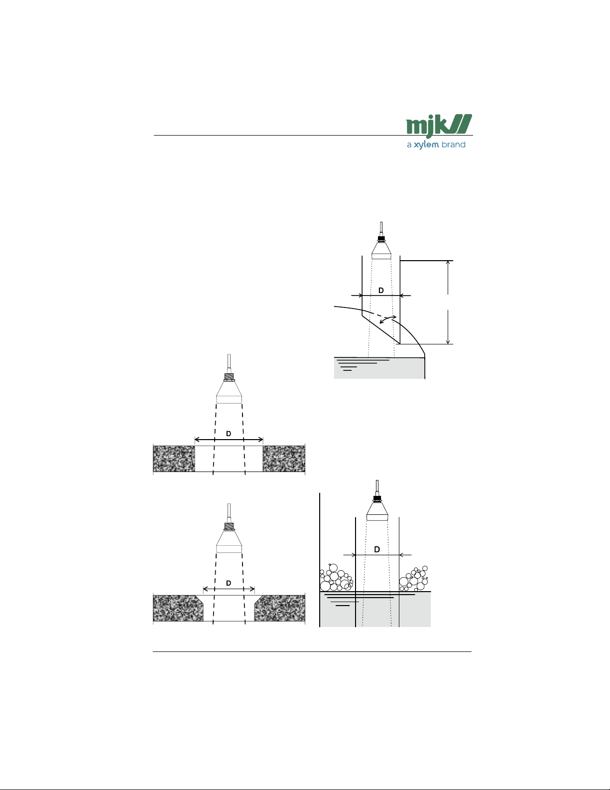
Through a concrete deck
When the ultrasonic sensor is measuring
through a concrete deck, the dimension
of the opening should be made as shown
below: (See table 1 for the sensor spread.)
Min. diameter (D)
= sensor spread +
100 %
In a tank / container
If the ultrasonic sensor is mounted for
measurement of the level in a closed tank or
container, it should measure through a pipe
with a cutoff as shown below:
Min. diameter (D) =
sensor spread + 100 %
Min. 14 in
30 - 45 °
Measurement in a closed container or tank.
Through pipe for foam protection
When measuring on liquids prone to build
up foam on the surface, it is often necessary
to measure through a pipe, since the build
up of foam rarely will occur inside the pipe.
Measurement through a concrete deck with
Measurement through a concrete deck with
US 2.10 Shuttle Manual 1510
sharp edge.
Min. diameter (D) =
45 - 60 ° edge cutoff.
sensor spread
+ 50 %
Min. diameter (D) =
sensor spread + 100 %
Measurement through a pipe for foam protection.
44
SW 838023
Find Quality Products Online at: [email protected]
www.GlobalTestSupply.com
Page 45

Shuttle® - Ultrasonic Level Transmitter
D Service menu
Shuttle® has a service menu that gives access to settings that normally are not altered
by the user and therefore are protected by a
password.
The service menu includes:
- adjustment of the 4-20 mA output
- adjustment of the temperature compensation
- functional control of keyboard and
display
- relay check
- changing of serial number and hardware/software numbers
- self test function
Refer to 'Shuttle® Service Manual' for further
information of the functions in the service
menu.
US 2.10 Shuttle Manual 1510
Find Quality Products Online at: [email protected]
www.GlobalTestSupply.com
45
SW 838023
Page 46

Shuttle® - Ultrasonic Level Transmitter
E Special menus
Under certain circumstances it may be necessary to make adjustments and to make
readings in the following special menus.
It is recommended that only experienced
users and MJK service technicians make
alterations in these menus.
The following menus are not protected with
an access code:
Bar graph read-out
Active measuring range
Response time
Measurement method
mA output value during system error
Calibraton of level readout
Offset level readout
Indication of echo signal quality
Indication of signal amplification
Indication of period length without echo
Selection of factory presets
The following menus are protected with an
access code:
Readout of version numbers
Find zero level on next power-up
Fixed mA signal
Interval between investigative
measurements
System alarm delay
Averaging the level measurement
Max. amplification level
Min. level for accept of ultrasonic echo
Sensitivity of the learning function
Changing the access code
US 2.10 Shuttle Manual 1510
Find Quality Products Online at: [email protected]
www.GlobalTestSupply.com
46
SW 838023
Page 47
Shuttle® - Ultrasonic Level Transmitter
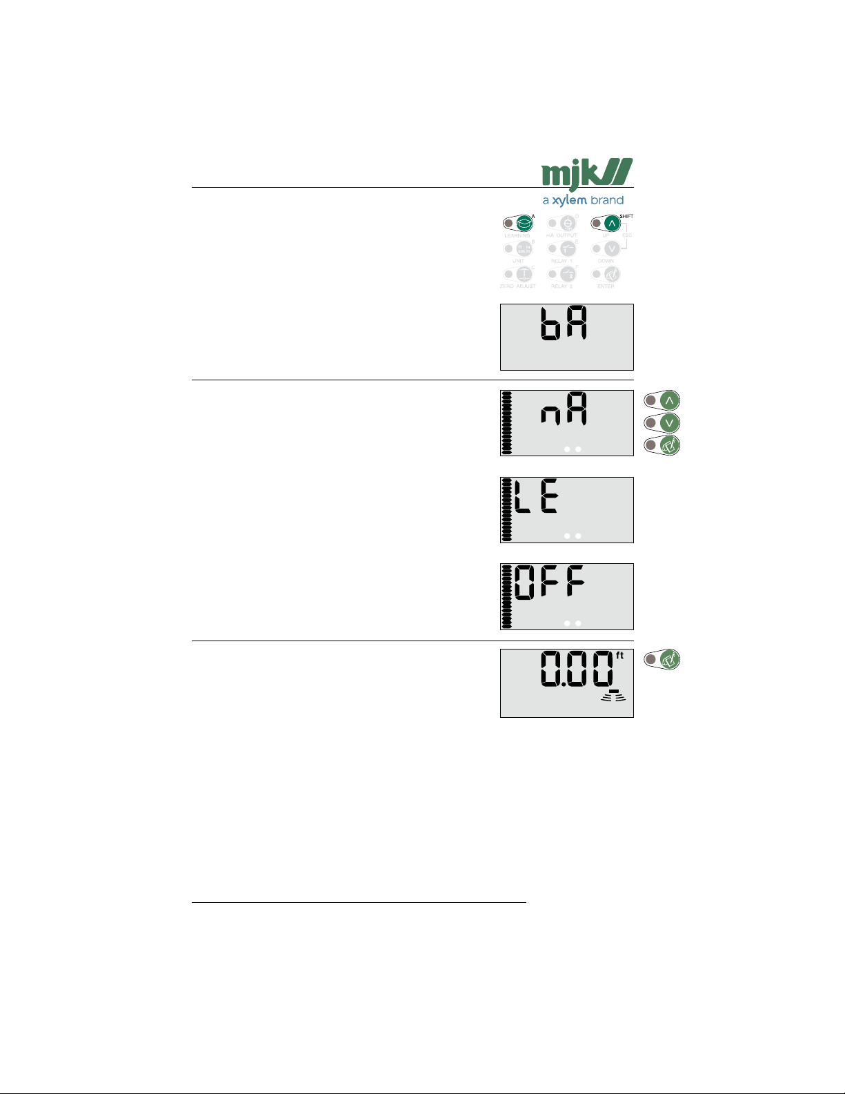
Bar graph read-out
This function is used to select whether the bar graph should
follow the analog output or the level read-out.
Changes will not have influence on the relay settings.
The bargraph follows the analog output.
Note: If the mA settings are inverted (the level reference
The bar graph follows the level read-out.
Note: If the active measuring range has been decre-
The bar graph is deactivated.
at 4 mA is set higher than the level reference at
20 mA), the bar graph will increase when the level
decreases and vice versa.
ased to i.e. 4.50 - 9 ft (see next page), the range
of the bar graph will be changed accordingly (all
segments lit at 9 ft and all segments off at 4.5 ft.)
Shuttle® reverts to normal read-out.
US 2.10 Shuttle Manual 1510
47
SW 838023
Find Quality Products Online at: [email protected]
www.GlobalTestSupply.com
Page 48
Shuttle® - Ultrasonic Level Transmitter
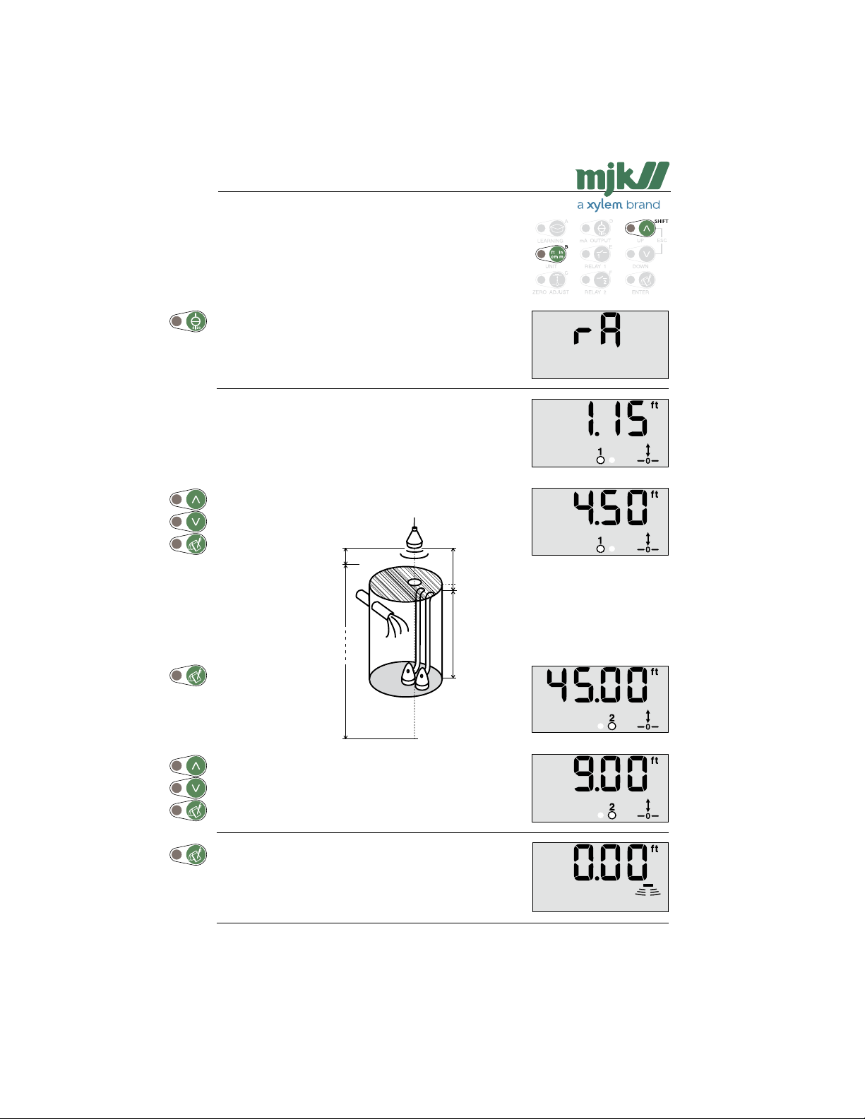
Active measuring range
Shuttle®'s measuring range is normally set automatically to
a distance corresponding to the ultrasonic sensor's distance
to zero level + 1.5 ft.
It may become necessary to decrease the active measuring
range so it corresponds to the highest and lowest possible
levels in the well /tank - especially if the ultrasonic sensor is
mounted above a steel grating or an opening in a well cover.
In this example, the Shuttle®'s active measuring range are
decreased from 14 in - 45 ft to 4.50 - 9 ft measured from
the sensor - that is 9.00 ft from the bottom to 4 in below the
grating or cover.
Set the start distance of the measuring range measured
from the ultrasonic sensor (i.e. the highest possible level).
0 ft
14 in
Normal
measuring
range
45.00 ft
0 ft
(4.00 ft)
4.50 ft
Reduced
measuring
range
9.00 ft
Set the stop distance of the measuring range measured from the
ultrasonic sensor (i.e. the lowest possible level).
Shuttle® reverts to normal read-out.
US 2.10 Shuttle Manual 1510
48
SW 838023
Find Quality Products Online at: [email protected]
www.GlobalTestSupply.com
Page 49
Shuttle® - Ultrasonic Level Transmitter
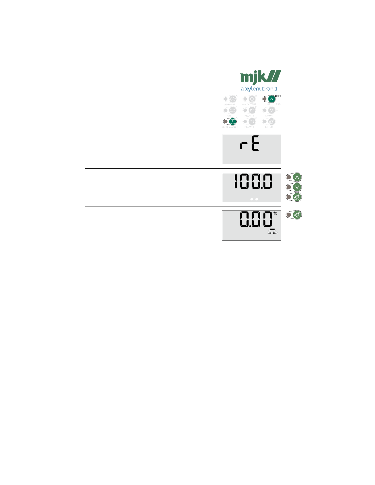
Response time
When the level changes, the display read-out will change
accordingly with a pre-programmed delay.
The response time is set to 100 mm/sec. (= 4 in/sec.) from
the factory, which means that an actual level change will not
be shown in the display at a faster rate than 4 in per second.
When measuring on turbulent surfaces, it may become
necessary to increase the response time in order to obtain a
more stable level measurement and also relay function.
Select the desired response time with the arrow keys.
Note: Changing the response time will also change the
Shuttle® reverts to normal read-out.
response time for the mA output and the time for
exceeding the set/reset levels.
US 2.10 Shuttle Manual 1510
Find Quality Products Online at: [email protected]
www.GlobalTestSupply.com
49
SW 838023
Page 50
Shuttle® - Ultrasonic Level Transmitter
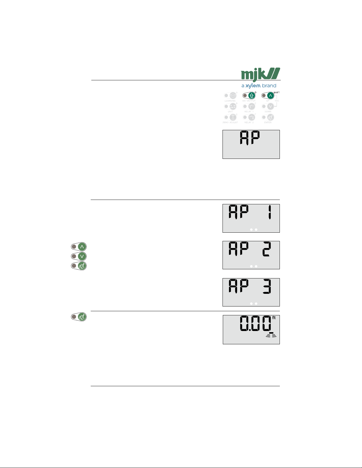
Measuring method (application)
Shuttle®'s high accuracy is partly obtained by controlling the
strength of the ultrasonic pulse based on the strength of the
received echo. (AP 1)
When performing level measurements on foaming surfaces,
granulate, sludge etc., the received echo is generally so
weak that it would be better to let Shuttle® send out the
ultrasonic pulses with full strength constantly. (AP 2)
Also, when performing level measurements on surfaces with
very rapid level changes, it can be necessary to moderate
the influence of the learning function (see also page 28) to
prevent Shuttle® from locking on false echos. (AP 3)
Select measuring method with arrow keys.
If 'AP 1' is selected, the ultrasonic pulse will be controlled in
accordance with the strength of the received echo.
'AP 1' should normally be selected for fluid applications.
If 'AP 2' is selected, Shuttle® will transmit with full strength
constantly.
'AP 2' should normally be selected for sludge / granulate
applications.
If 'AP 3' is selected, Shuttle® will be better to catch rapid
level changes.
'AP 3' should normally be selected for measuring in sludge
containers, grating matter or other aqueous matter.
Shuttle® reverts to normal read-out.
US 2.10 Shuttle Manual 1510
50
SW 838023
Find Quality Products Online at: [email protected]
www.GlobalTestSupply.com
Page 51
Shuttle® - Ultrasonic Level Transmitter
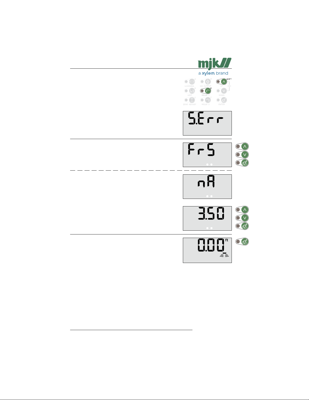
mA output signal during system error
This function determines how the mA output should act in
case of a system error.
System errors are most often caused by a weak or missing
ultrasonic echo, but may also occur by failure of the ultrasonic sensor or failure in Shuttle®'s internal circuits.
Select the desired condition with the arrow keys.
The mA output will be locked on the last known value when
a system error occurs.
The mA output will give a fixed signal when a system error
occurs.
Select the desired value (0.35 to 20.5 mA) of the fixed signal
with the arrow keys.
Shuttle® reverts to normal read-out.
US 2.10 Shuttle Manual 1510
51
SW 838023
Find Quality Products Online at: [email protected]
www.GlobalTestSupply.com
Page 52
Shuttle® - Ultrasonic Level Transmitter
Calibration of the level measurement
If the distance of the ultrasonic sensor above the surface is
known, it will be possible make a calibration of Shuttle®'s
level read-out.
The calibration will only have influence on the level read-out
- not on relay setpoints for pump control, alarms etc.
Note: Because of the built-in temperature compensation,
Select the desired correction with the arrow keys.
If the learning function has been activated, Shuttle® will
deactivate the learning function and erase the suspicious
levels that were found last time the learning function was
activated.
The learning function must therefore both be started and
reactivated again.
If the relay outputs are configured for pump control, the
relays will be deactivated, but their limit settings will not be
erased. Also, delay settings and other settings will not be
erased.
it is important that the ultrasonic sensor has the
same temperature as the surrounding air. Leave
the sensor in the surrounding air for minimum 1
hour.
Shuttle® reverts to normal read-out.
US 2.10 Shuttle Manual 1510
52
SW 838023
Find Quality Products Online at: [email protected]
www.GlobalTestSupply.com
Page 53
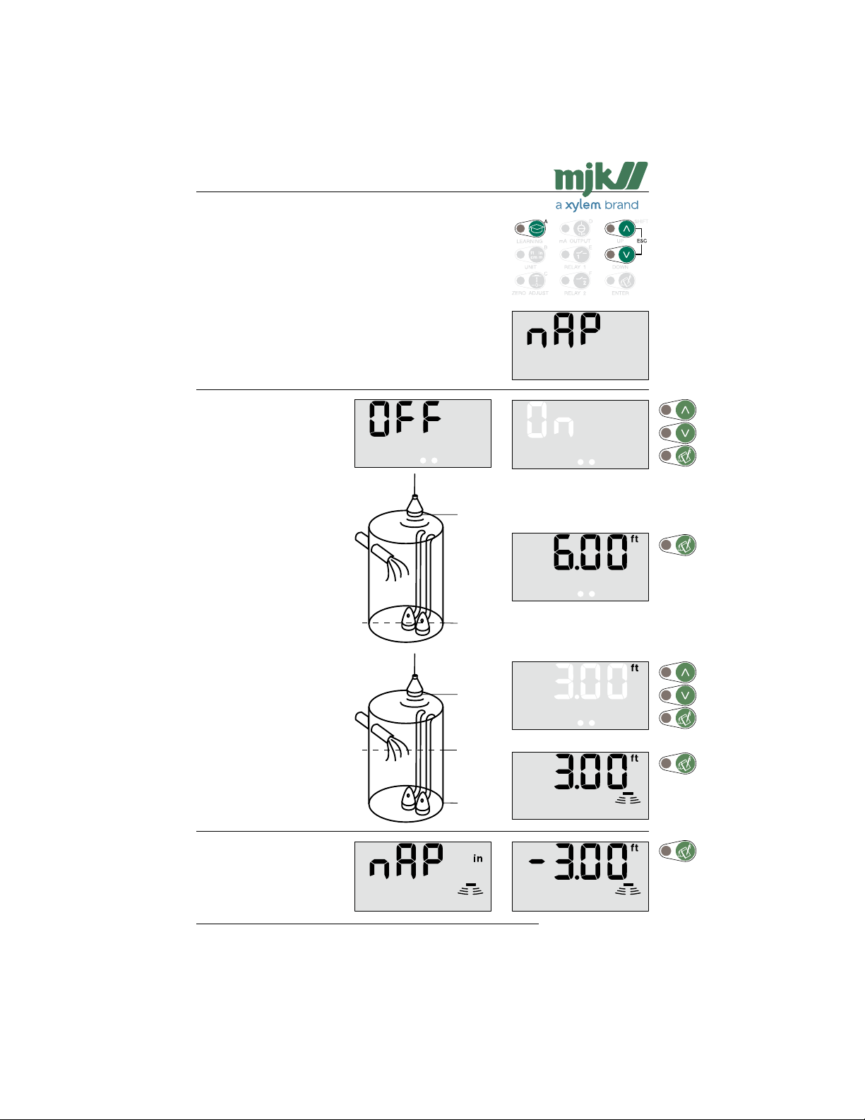
Shuttle® - Ultrasonic Level Transmitter
Offset level readout
Shuttle® can display the levels with reference to a selectable
offset level (datum).
This means that the normal zero level (when the tank is
empty) is displaced up or down.
Note: It is very important, that the distance from sensor
Shuttle® wil now display the
level as the distance from
sensor to zero.
to zero is set correctcly (see page 18), and that
the active measuring range (see page 48) is set to
a distance, that corresponds to the longest meaasuring distance that can occur.
6.00 ft
Zero refer-
Select the desired zero reference with the arrow keys
and confirm with 'Enter'.
Zero refer-
Shuttle® reverts to normal
read-out. Every 5 seconds
the display indicates that
the level readouts are displaced from zero.
US 2.10 Shuttle Manual 1510
ence
ence
53
0.00 ft
3.00 ft
0.00 ft
-3.00 ft
SW 838023
Find Quality Products Online at: [email protected]
www.GlobalTestSupply.com
Page 54
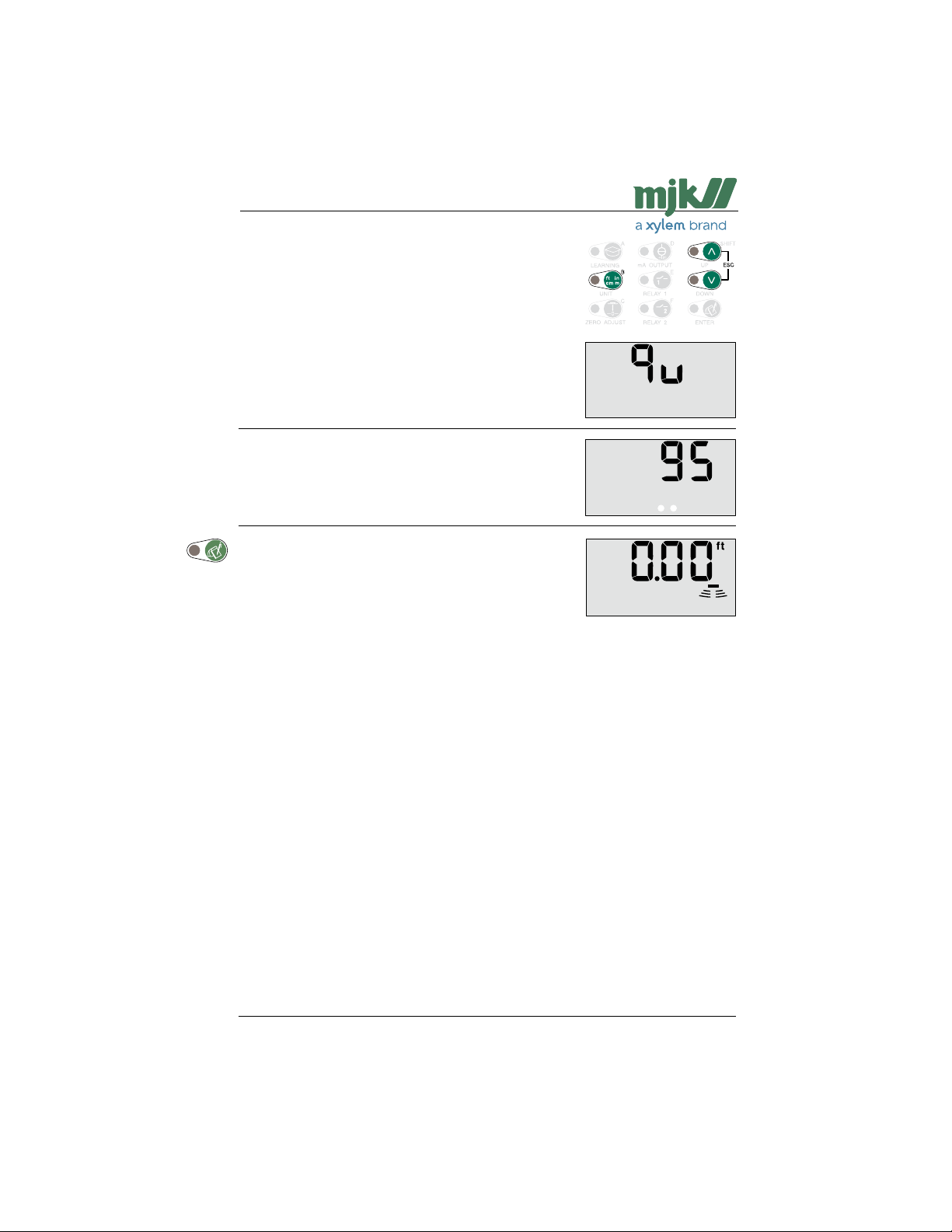
Shuttle® - Ultrasonic Level Transmitter
Indication of echo quality
This menu is used to indicate the strength of the received
ultrasonic echo.
If there are frequent system errors (see page 32), this
function can be used to check if the ultrasonic echo is being
weakened too much under the current working conditions
- i.e. foam, waves etc.
There are no specific limits indicating that the echo is too
weak, since it depends highly on the current working conditions. Please contact MJK for advice.
The strength of the received ultrasonic echo is displayed
immediately.
(The strenght is shown in percent.)
Shuttle® reverts to normal read-out.
US 2.10 Shuttle Manual 1510
Find Quality Products Online at: [email protected]
www.GlobalTestSupply.com
54
SW 838023
Page 55
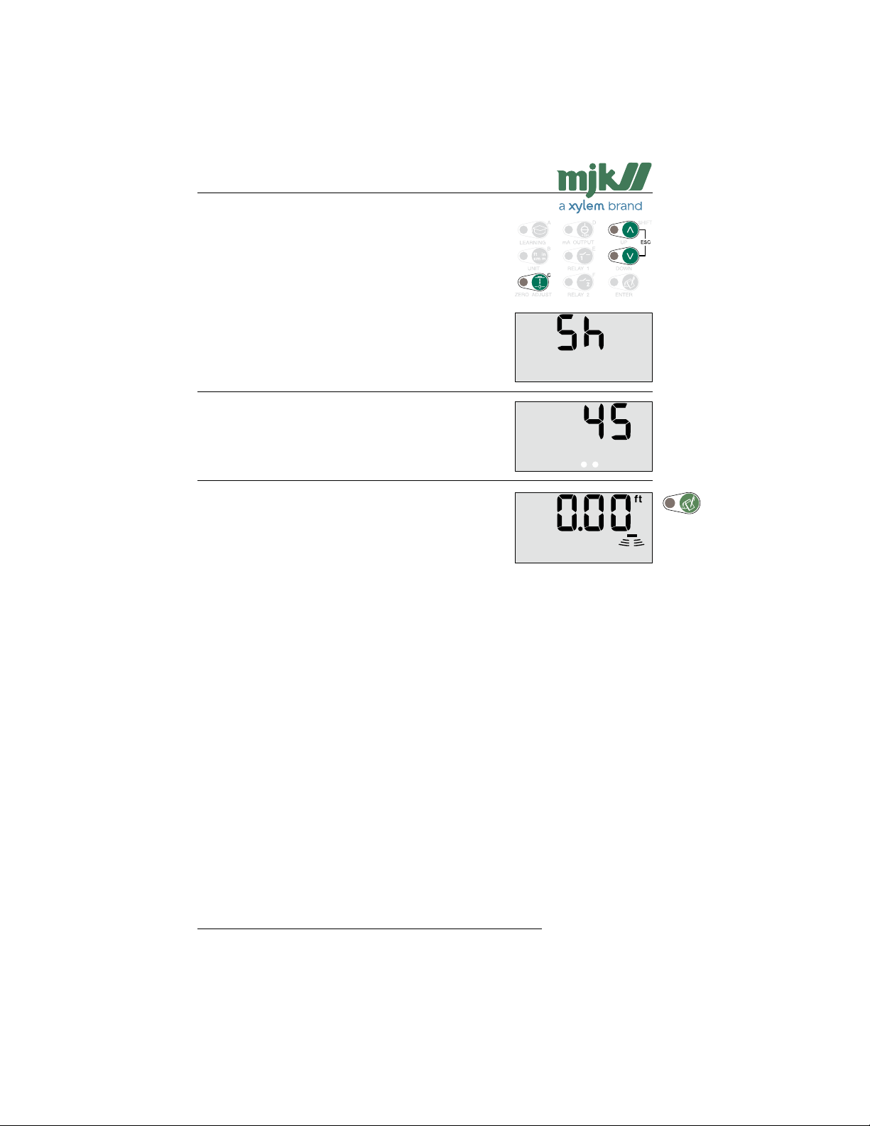
Shuttle® - Ultrasonic Level Transmitter
Indication of signal amplification
This menu is used to display the amplification level of the
received ultrasonic echo. The function can give an indication
og the strength of the received echo.
If the amplification level is low (below. 20 dB), the echo
strength is good and vice versa.
A high amplification level (max. 50 dB) indicate that the
ultrasonic echo is weak (foam or waves).
High amplification may in certain situations create other
problems with electrical noise from other equipment at the
installation site.
The amplification level is displayed immediately.
(The level is displayed in dB)
Shuttle® reverts to normal read-out.
US 2.10 Shuttle Manual 1510
Find Quality Products Online at: [email protected]
www.GlobalTestSupply.com
55
SW 838023
Page 56
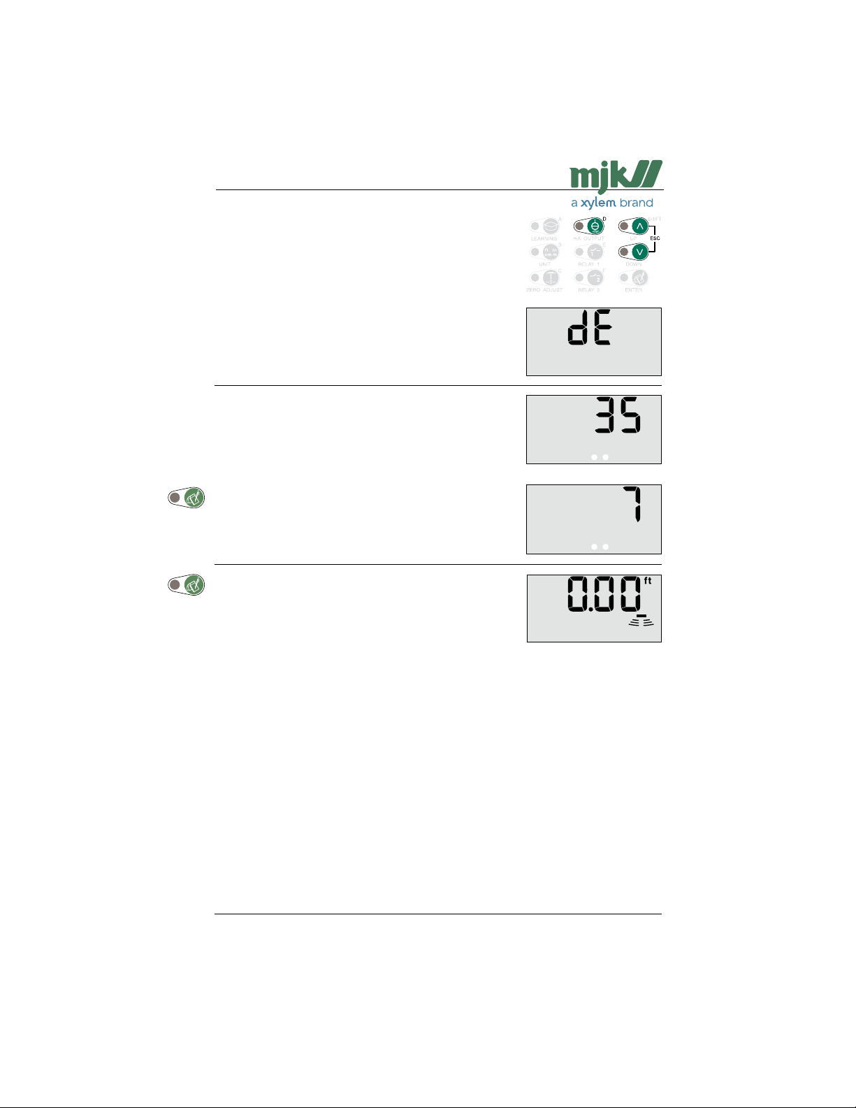
Shuttle® - Ultrasonic Level Transmitter
Indication of time period without echo
This menu is used to display the longest time period during
which Shuttle® has been missing an acceptable echo, and
also how many days has passed since this occurred.
The longest time period that Shuttle® has been missing an
acceptable echo is displayed immediately.
(In seconds.)
Next, the number of days since the occurrence is displayed.
The longest period with echo failure will be erased after 14
days.
Shuttle® reverts to normal read-out.
US 2.10 Shuttle Manual 1510
Find Quality Products Online at: [email protected]
www.GlobalTestSupply.com
56
SW 838023
Page 57
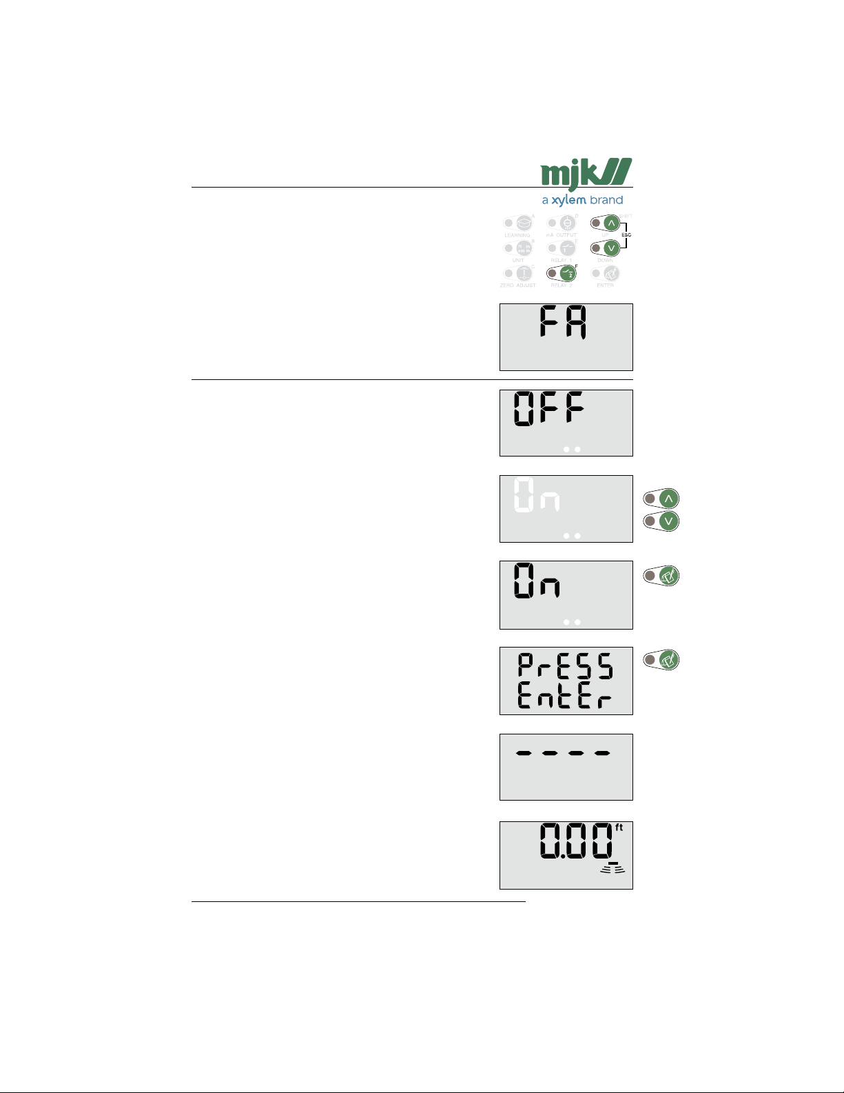
Shuttle® - Ultrasonic Level Transmitter
Select factory settings
All settings - except calibration of the level measurement
- made after initial startup will be reset to factory settings
with this function.
The zero point setting will also be adjusted to the immediate
level in the well / tank. Furthermore, the mA output is set to
4 mA at the current zero point and 20 mA at a level corresponding to a distance of 14 in from the ultrasonic sensor.
Note: The function will cause Shuttle® to start up the
Select 'ON' with the arrow keys.
same way it did when the supply power was
turned on for the first time.
This is shown in the display until Shuttle® detects a valid
echo again.
... after which Shuttle® returns to normal read-out.
US 2.10 Shuttle Manual 1510
Find Quality Products Online at: [email protected]
www.GlobalTestSupply.com
57
SW 838023
Page 58
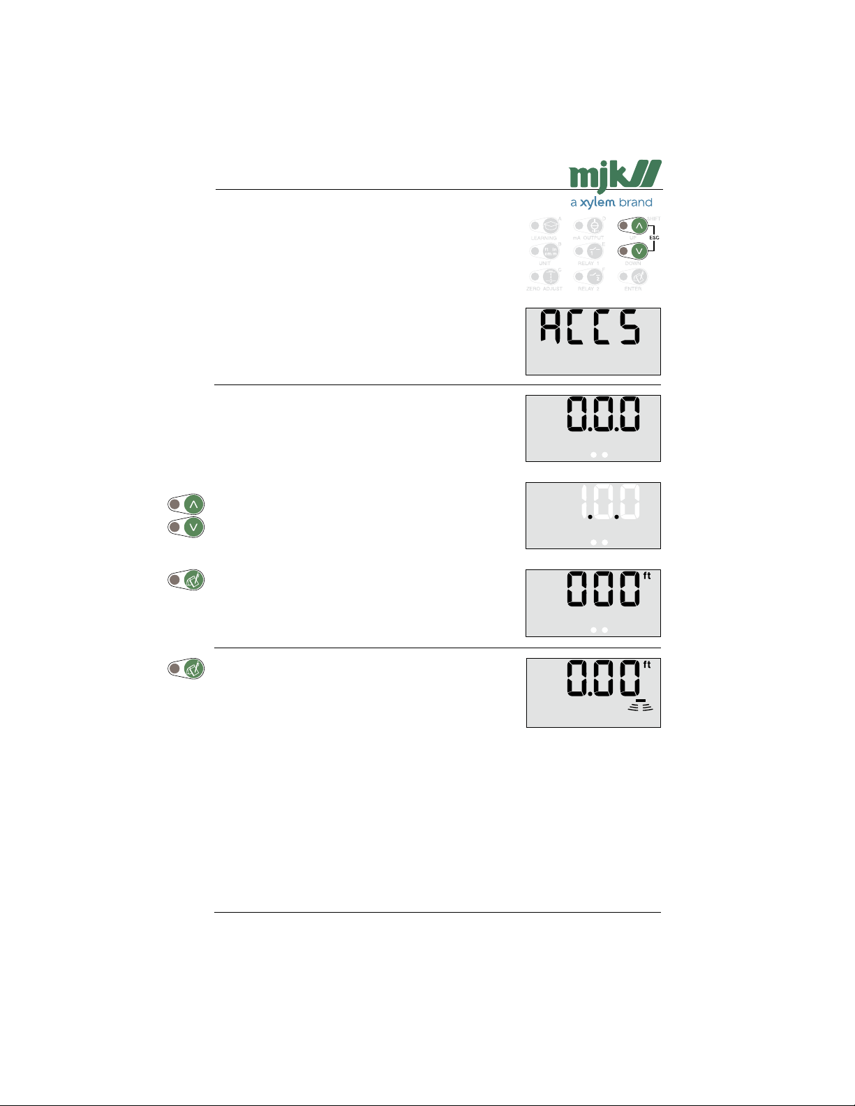
Shuttle® - Ultrasonic Level Transmitter
Access code
To gain acces to the remaining menus, an access code is
required.
Press and hold 'Escape' in minimum 5 seconds:
The access code can now be selected:
Use the arrow keys to select…
(Standard access code is 100:)
…and confirm with 'ENTER':
All password protected menus can now be selected.
Shuttle® will display the current level readings between menu
selections.
Shuttle® will revert to normal readout if:
1: the keyboard has not been used within 5 minutes.
2: 'Escape' is pressed.
The acces code must then be entered again for access to
the password protected menus.
US 2.10 Shuttle Manual 1510
58
SW 838023
Find Quality Products Online at: [email protected]
www.GlobalTestSupply.com
Page 59
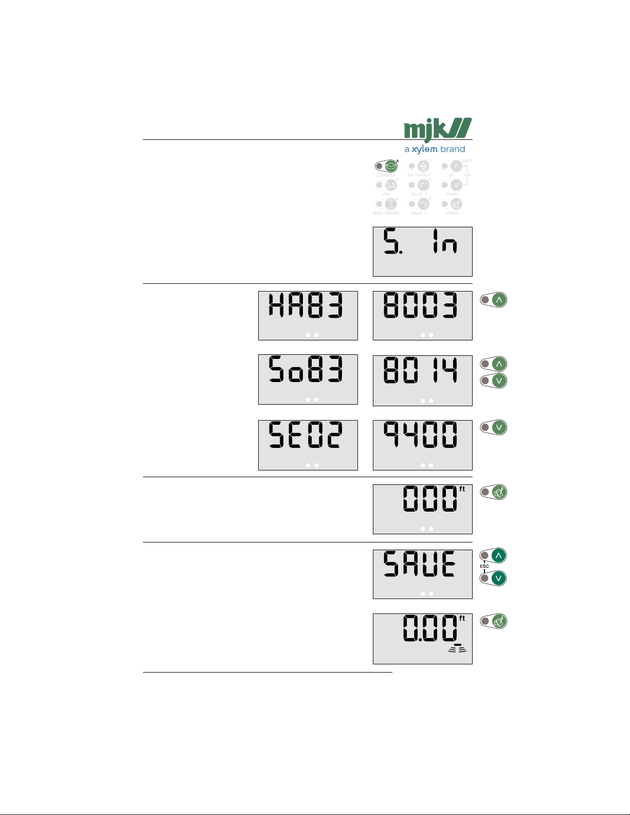
Shuttle® - Ultrasonic Level Transmitter
Readout of version numbers
Enter the access code (see page 58) and press'A':
This menu is used to display version numbers for software
and hardware and the unit's serial number.
The hardware version number
is displayed first:
(Ex.: HW version 838003)
Use the up-arrow to proceed.
The software version number is
displayed next:
(Ex.: SW version 838014)
Use the arrows to proceed.
At last the Shuttle®'s serial
number is displayed:
(Ex.: serial no. 029400)
Use the down-arrow to proceed.
Shuttle® is ready for a new selection of a password protected menu after pressing 'Enter'.
(Re-entering the access code is not necessary if a menu
selection is made within 5 minutes.)
Press 'Escape' if no further password protected menu
selections are needed …
... or confirm with 'Enter' that the changes should be saved,
whereupon Shuttle® revert to normal read-out, and the next
password protected menu can be selected.
(Press 'Escape' if the changes should not be saved.)
US 2.10 Shuttle Manual 1510
59
SW 838023
Find Quality Products Online at: [email protected]
www.GlobalTestSupply.com
Page 60
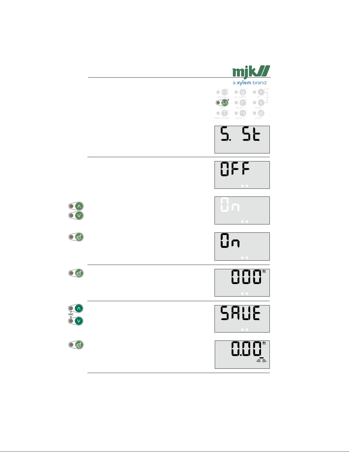
Shuttle® - Ultrasonic Level Transmitter
Find zero level at next power-up
Enter the access code (see page 58) and press 'B':
This menu is used to force Shuttle® to start up with an auto-
matic zero level setting at the next power-up. (See page 14.)
The function is useful if ie. Shuttle® has been build into a
control panel and has been set-up for a particular application. Shuttle® will then start up as it would when delivered
from the factory, but the selected functions and setpoints will
not be reset.
Use the arrow keys to select:
Confirm the new setting:
Shuttle® is ready for a new selection of a password protected menu after pressing 'Enter'.
(Re-entering the access code is not necessary if a menu
selection is made within 5 minutes.)
Press 'Escape' if no further password protected menu
selections are needed …
... or confirm with 'Enter' that the changes should be saved,
whereupon Shuttle® revert to normal read-out, and the next
password protected menu can be selected.
(Press 'Escape' if the changes should not be saved.)
US 2.10 Shuttle Manual 1510
60
SW 838023
Find Quality Products Online at: [email protected]
www.GlobalTestSupply.com
Page 61
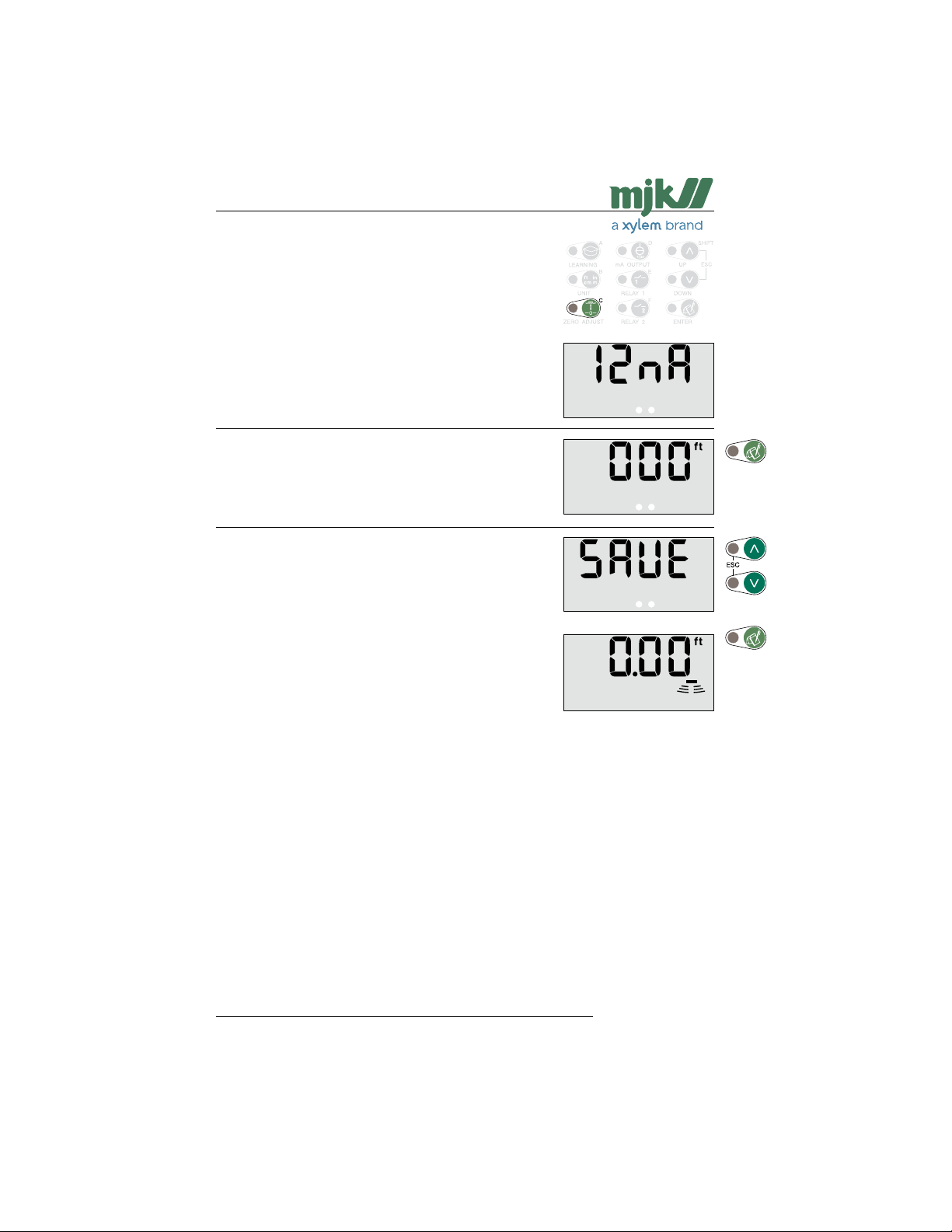
Shuttle® - Ultrasonic Level Transmitter
Fixed mA signal
Enter the access code (see page 58) and press 'C'.
This menu is used to make Shuttle® give out a constant 12
mA signal independent of the actual level readout.
The function can be useful during trouble shooting on exter-
nal equipment.
Note: The output signal is constant 12 mA as long as
Shuttle® is ready for a new selection of a password protected menu after pressing 'Enter'.
(Re-entering the access code is not necessary if a menu
selection is made within 5 minutes.)
Press 'Escape' if no further password protected menu
selections are needed …
... or confirm with 'Enter' that the changes should be saved,
whereupon Shuttle® revert to normal read-out, and the next
password protected menu can be selected.
(Press 'Escape' if the changes should not be saved.)
this display is shown:
US 2.10 Shuttle Manual 1510
Find Quality Products Online at: [email protected]
www.GlobalTestSupply.com
61
SW 838023
Page 62
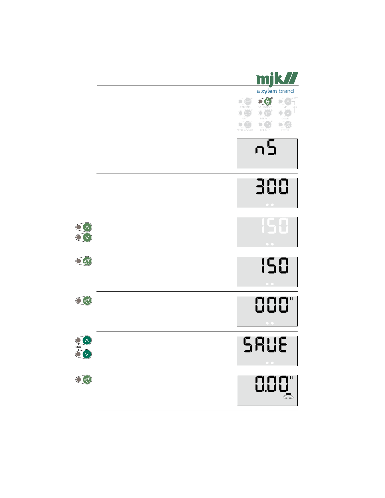
Shuttle® - Ultrasonic Level Transmitter
Investigative measurement intervals
Enter the access code (see page 58) and press 'D':
Shuttle® will normally perform an investigative measurement
every 5 minutes in order to ensure that the unit has not
locked on a false echo - i.e. a level signal which is not the
actual level.
If Shuttle® often locks onto solid objects within the normal
interval, the interval for investigative measurements can be
changed in this menu.
The actual setting is shown immediately:
(Value in seconds.)
Use the arrow keys to select a new value:
Confirm the new setting:
Shuttle® is ready for a new selection of a password protected menu after pressing 'Enter'.
(Re-entering the access code is not necessary if a menu
selection is made within 5 minutes.)
Press 'Escape' if no further password protected menu
selections are needed …
... or confirm with 'Enter' that the changes should be saved,
whereupon Shuttle® revert to normal read-out, and the next
password protected menu can be selected.
(Press 'Escape' if the changes should not be saved.)
US 2.10 Shuttle Manual 1510
62
SW 838023
Find Quality Products Online at: [email protected]
www.GlobalTestSupply.com
Page 63
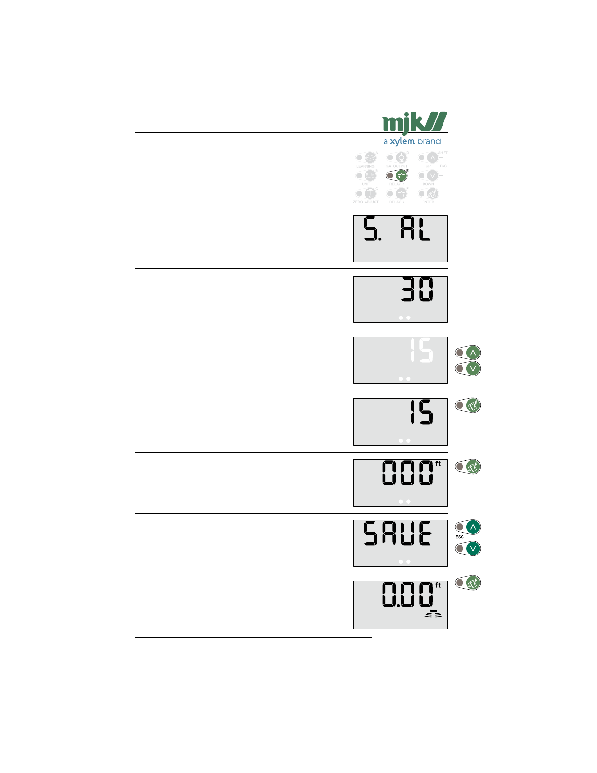
Shuttle® - Ultrasonic Level Transmitter
System alarm delay
Enter the access code (see page 58) and press 'E':
Shuttle® will give a system alarm (see page 32), if an ac-
ceptable echo has not been present within a preset period
of time.
If it is very important to know that the level measurement is
valid at all times, the delay should eventually be decreased.
The actual setting is shown immediately:
(Value in seconds.)
Use the arrow keys to select a new value:
Confirm the new setting:
Shuttle® is ready for a new selection of a password protected menu after pressing 'Enter'.
(Re-entering the access code is not necessary if a menu
selection is made within 5 minutes.)
Press 'Escape' if no further password protected menu
selections are needed …
... or confirm with 'Enter' that the changes should be saved,
whereupon Shuttle® revert to normal read-out, and the next
password protected menu can be selected.
(Press 'Escape' if the changes should not be saved.)
US 2.10 Shuttle Manual 1510
63
SW 838023
Find Quality Products Online at: [email protected]
www.GlobalTestSupply.com
Page 64
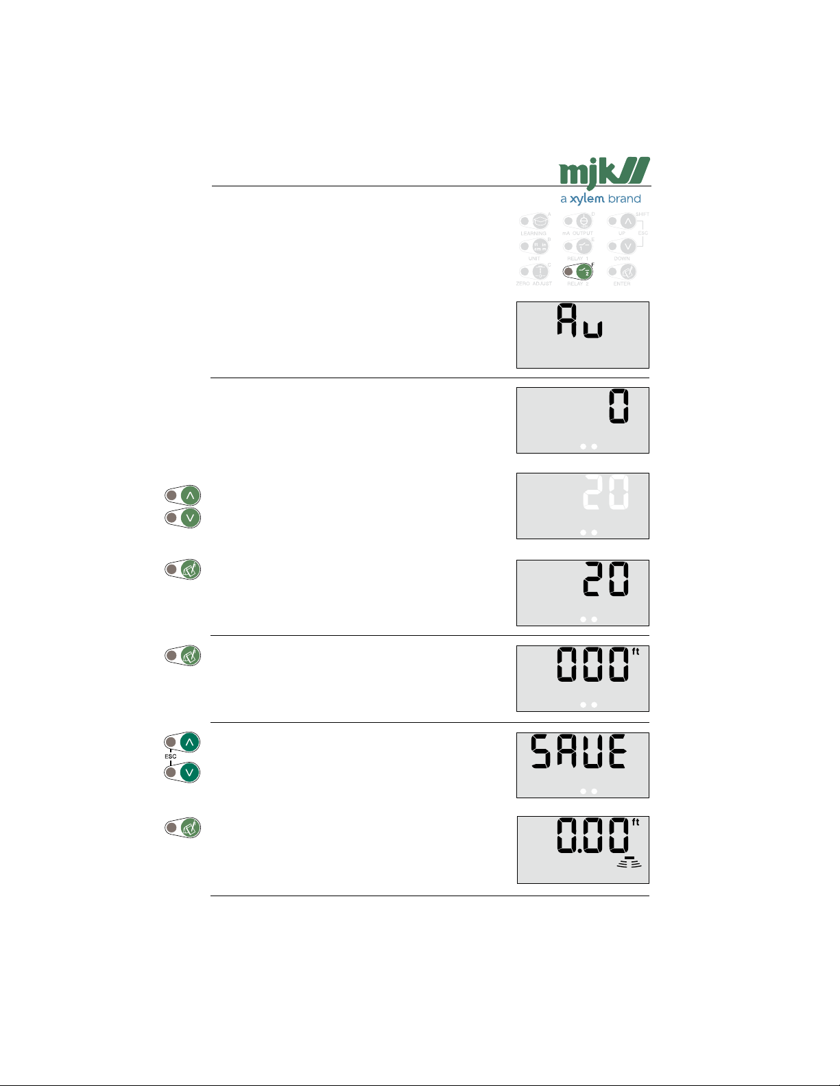
Shuttle® - Ultrasonic Level Transmitter
Averaging the level measurement
Enter the access code (see page 58) and press 'F':
When measuring on very turbulent liquid surfaces, it may be
needed to average the level changes in order to gain a more
steady level readout and level signal.
This menu is used to set the time from a level change is
measured and until the reading will be 99 % of the level
change.
See also page 49, 'Response time'.
The actual setting is shown immediately:
(Value in seconds.)
Use the arrow keys to select a new value:
Confirm the new setting:
Note: The variation on the mA output will change ac-
cordigly.
Shuttle® is ready for a new selection of a password protected menu after pressing 'Enter'.
(Re-entering the access code is not necessary if a menu
selection is made within 5 minutes.)
Press 'Escape' if no further password protected menu
selections are needed …
... or confirm with 'Enter' that the changes should be saved,
whereupon Shuttle® revert to normal read-out, and the next
password protected menu can be selected.
(Press 'Escape' if the changes should not be saved.)
US 2.10 Shuttle Manual 1510
64
SW 838023
Find Quality Products Online at: [email protected]
www.GlobalTestSupply.com
Page 65
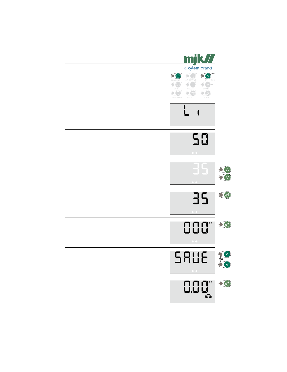
Shuttle® - Ultrasonic Level Transmitter
Max. amplification level
Enter the access code (see page 58) and press 'Shift' + 'A':
If Shuttle® periodically has a system error and/or the level
readout jumps to a high or low level during measuring in
favourable conditions, it may be necessary to limit the amplification of the received echo. (See also page 66.)
The effect from electrical noise can also be reduced or eliminated with this function.
Note: A reduction in the amplification level may affect the
The actual setting is shown immediately:
(Value in dB.)
Use the arrow keys to select a new value:
(5 dB increments.)
Confirm the new setting:
maximum measuring range.
Shuttle® is ready for a new selection of a password protected menu after pressing 'Enter'.
(Re-entering the access code is not necessary if a menu
selection is made within 5 minutes.)
Press 'Escape' if no further password protected menu
selections are needed …
... or confirm with 'Enter' that the changes should be saved,
whereupon Shuttle® revert to normal read-out, and the next
password protected menu can be selected.
(Press 'Escape' if the changes should not be saved.)
US 2.10 Shuttle Manual 1510
65
SW 838023
Find Quality Products Online at: [email protected]
www.GlobalTestSupply.com
Page 66
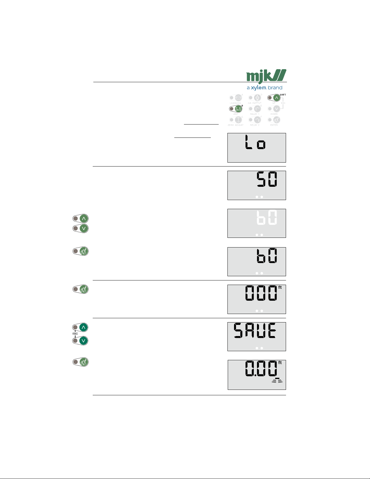
Shuttle® - Ultrasonic Level Transmitter
Min. level for accept of ultrasonic echo
Enter the access code (see page 58) and press 'Shift' + 'B':
If Shuttle® periodically has a system error and/or the level
readout jumps to a high or low level during measuring in favourable conditions, it may be necessary to increase the limit
for accept of the ultrasonic echo. (See also page 65.)
On the contrary, it can be necessary to decrease the limit, if
it is difficult to get a good echo, e.g. long measuring distances on difficult surfaces.
Note: Changes may affect the possible measuring range.
The actual setting is shown immediately:
(Value in seconds.)
Use the arrow keys to select a new value:
Confirm the new setting:
Shuttle® is ready for a new selection of a password protected menu after pressing 'Enter'.
(Re-entering the access code is not necessary if a menu
selection is made within 5 minutes.)
Press 'Escape' if no further password protected menu
selections are needed …
... or confirm with 'Enter' that the changes should be saved,
whereupon Shuttle® revert to normal read-out, and the next
password protected menu can be selected.
(Press 'Escape' if the changes should not be saved.)
US 2.10 Shuttle Manual 1510
66
SW 838023
Find Quality Products Online at: [email protected]
www.GlobalTestSupply.com
Page 67
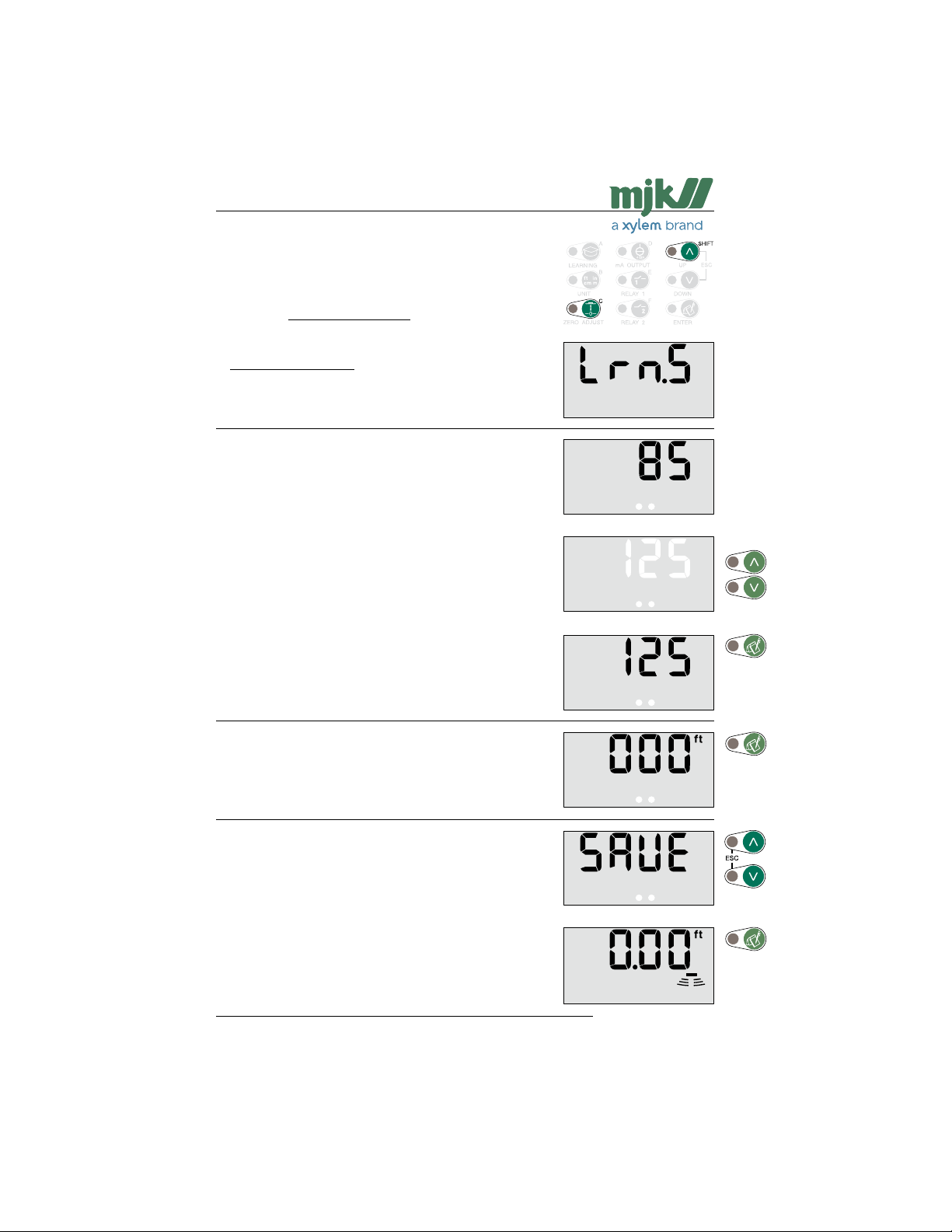
Shuttle® - Ultrasonic Level Transmitter
Sensitivity of the learning function
Enter the access code (see page 58) and press 'Shift' + 'C':
If Shuttle® periodically is locked on a false echo, even if the
learning function has been activated (see page 28), it may be
necessary to increase the sensitivity of the acoustic image
that was stored in Shuttl e® during the learning process.
On the contrary, under rare occasions it may be necessary
to decrease the sensitivity under particular acoustic occasions, where double echos may occur that causes Shuttle®
to lock.
The actual setting is shown immediately:
(Value in percent.)
Use the arrow keys to select a new value:
Confirm the new setting:
Shuttle® is ready for a new selection of a password protected menu after pressing 'Enter'.
(Re-entering the access code is not necessary if a menu
selection is made within 5 minutes.)
Press 'Escape' if no further password protected menu
selections are needed …
... or confirm with 'Enter' that the changes should be saved,
whereupon Shuttle® revert to normal read-out, and the next
password protected menu can be selected.
(Press 'Escape' if the changes should not be saved.)
US 2.10 Shuttle Manual 1510
67
SW 838023
Find Quality Products Online at: [email protected]
www.GlobalTestSupply.com
Page 68
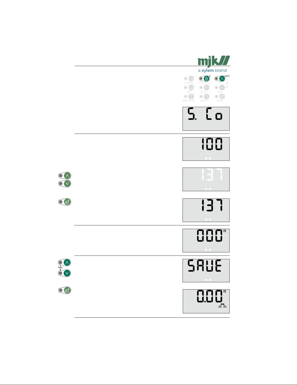
Shuttle® - Ultrasonic Level Transmitter
Changing the access code
Enter the access code (see page 58) and press 'Shift' + 'D'
The actual setting is shown immediately:
Use the arrow keys to select a new access code:
Confirm the new setting:
Shuttle® is ready for a new selection of a password protected menu after pressing 'Enter'.
(Re-entering the access code is not necessary if a menu
selection is made within 5 minutes.)
Press 'Escape' if no further password protected menu
selections are needed …
... or confirm with 'Enter' that the changes should be saved,
whereupon Shuttle® revert to normal read-out, and the next
password protected menu can be selected.
(Press 'Escape' if the changes should not be saved.)
US 2.10 Shuttle Manual 1510
68
SW 838023
Find Quality Products Online at: [email protected]
www.GlobalTestSupply.com
Page 69
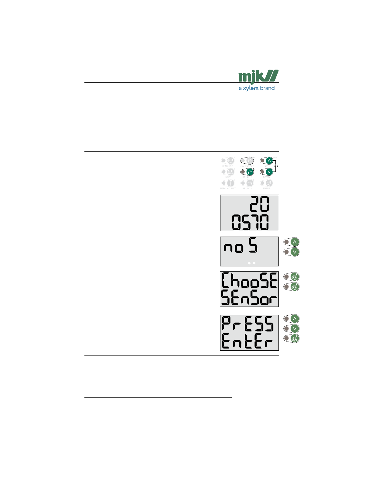
Shuttle® - Ultrasonic Level Transmitter
F New sensor / changing sensor
Shuttle® will be shipped and delivered from about July 1,
2007 with 1 of 4 different sensor types.
If, at some other time, the sensor is to be replaced by
another or a newer type, the following procedure can successfully be applied to re-configure the level transmitter.
Technical specifications are located on pages 37 - 41.
Open the choose sensor menu
Press 'Esc' + 'E'.
Consequently the (previously) selected sensor type is displayed (here: 20 and 0570 for sensor type 200570):
Press the 'Up' or 'Down' arrow key repeatedly until the following static display appears (no sensor):
Press 'Enter' twice whereafter the following menu travels
across the screen (Choose Sensor Press Enter):
Shuttle is now in the opening menu for a Shuttle delivered
without a sensor.
Press 'Enter' to enter the choose sensor menu, and press
the 'Up' or 'Down' arrow key repeatedly, until the required
sensor type appears.
Press 'Enter' to finish the configuration.
See also page 14, 'Get started'.
Note: Once a sensor type has been selected, the factory
settings will not alter this selection.
US 2.10 Shuttle Manual 1510
69
SW 838023
Find Quality Products Online at: [email protected]
www.GlobalTestSupply.com
Page 70

Shuttle® - Ultrasonic Level Transmitter
Warranty
MJK products carry a one-year limited warranty against defects in materials or workmanship and that they will comply
with written specifications supplied by MJK current at the time of shipment to the customer. The Warranty period begins
once the product is installed or otherwise put into operation or 90 days after the date of delivery to the buyer, whichever is
soonest. MJK products are not warranted against abuse, misuse, or normal wear and tear. MJK will at MJK’s discretion,
repair or exchange defective product covered under warranty at no cost to the buyer provided the buyer returns the item,
freight prepaid to MJK with a return authorization issued by MJK. The buyer is liable for expenses and risks, associated with
return delivery to our company. MJK is not liable for direct or indirect damages due to product failure under warranty or out
of warranty.
Liability
MJK’s liability is limited to the costs of its products and services, unless otherwise indicated by state law.
MJK Automation ApS is liable to the common rules of Danish law on product liability, however, the liability is reduced to
coverage of our public liability insurance of products. To the extent where nothing else follows in lines of invariable rules of
law, we are not liable for loss of profits and working deficits or other indirect losses.
Return of goods
Products custom manufactured to the specifications of a customer cannot be returned, nor can an order for custom products be cancelled except with written permission from MJK. Standard products can only be returned with a return goods
authorization issued by MJK. Returns of goods ordered in error or for stock reduction purposes, which are returned unused
in their original packaging and in their original condition, will be accepted when return authorization is obtained and with
acknowledgement that the buyer will be assessed a 10% re-stocking charge based on the purchase
price of the product. Product credit less the restocking charge will be issued upon inspection of the
returned goods by MJK. The buyer is responsible for expenses and risks of return delivery to our
company.
Changes
As our products are developed continuously, we reserve the right to
make any alterations without prior notice.
US 2.10 Shuttle Manual 1510
Find Quality Products Online at: [email protected]
www.GlobalTestSupply.com
70
SW 838023
 Loading...