

Page 1

JACKSON SPINAL SURGERY TOPS
AND 5927 RADIOLUCENT IMAGING TOP
OWNER’S MANUAL
Models 5943 & 5943AP
This manual is written in five
languages in the following order:
(en) English
(es) Spanish
(fr) French
(de) German
(it) Italian
MIZUHO OSI
30031 AHERN AVENUE UNION CITY, CA 94587
Bus: 510-429-1500 Toll Free: 800-777-4674 Fax: 510-429- 85 0 0
WWW.MIZUHOSI.COM ·
NEWHIPNEWS.COM · NEWSPINENEWS.COM
MIZUHOSI 2009 NW0504 Rev. D 1
Page 2

IMPORTANT NOTICES
CAUTION: To ensure safe operation of the equipment, please READ THESE
INSTRUCTIONS COMPLETELY and keep this manual readily available to operating
room personnel for future reference.
Carefully observe and comply with all warnings, cautions and instructions which are
printed on the equipment or described in this manual.
The WARNING
symbol in this manual is intended to alert the user to the presence
of important operation, maintenance, or safety instructions.
Warning:
Proper pre-operative and intra-operative procedures must be followed to prevent
venous stasis and pooling, pressure sore development, neuropathy, improper
electrosurgical tissue grounding, hypotension and hypothermia.
NOTE: The application techniques outlined in these instructions are the manufacturer’s
suggested techniques. The final disposition of each patient’s care as related to the use
of this equipment rests with the attending physician.
This device is to be used by trained personnel only.
PROTECTION AGAINST ELECTRICAL SHOCK HAZARD:
This symbol indicates this equipment is an applied part, TYPE B in
accordance with IEC 60601-1 and is generally suitable for applications involving
external or internal contact with the patient, excluding the heart. The patient
circuit is connected to a protective earth ground, and this equipment should be
connected only to outlets with a protective earth ground.
This symbol indicates an external ground stud that is required for use
when the AC power cable is not connected to a protective earth ground outlet in
your operating room or facility.
To protect the patient and hospital staff from any possible hazards, an external
ground wire connection is required between the external ground stud and
protective earth ground.
Warning:
Medical electrical equipment needs special precautions regarding EMC and
needs to be installed and put into service according to the EMC information
provided in this manual.
MIZUHOSI 2009 NW0504 Rev. D
2
Page 3

Warning:
Portable and mobile RF communications equipment can affect medical electrical
equipment.
Warning:
This equipment should not be used adjacent to or stacked with other equipment
and that if adjacent or stacked use is necessary, the equipment should be
observed to verify normal operation in the configuration in which it will be used.
Warning:
The use of accessories, transducers and cables other than those specified by
MIZUHO OSI may result in increased emissions or decreased immunity of the
equipment.
Disposal of Electrical Components
In accordance with the WEEE directive, all electrical components, batteries and
carbon composite components must be returned to Mizuho OSI for proper
disposal. Please contact Mizuho OSI Technical Service Department at 1-800-7774674 for further information regarding this requirement.
MIZUHOSI 2009 NW0504 Rev. D
3
Page 4

TABLE OF CONTENTS
OVERVIEW.........................................................................................................................................6
1.0
1.1 General Description ......................................................................................................................6
1.2 Storage..........................................................................................................................................6
1.3 Acceptance & Transfer..................................................................................................................6
1.4 Inspection and Transfer ................................................................................................................6
2.0 COMPONENT IDENTIFICATION.......................................................................................................7
2.1 Jackson Spinal Surgery Top.........................................................................................................7
2.2 Radiolucent Imaging Top..............................................................................................................8
2.3 H-Frame........................................................................................................................................8
2.4 T-Pin..............................................................................................................................................9
2.5 Patient Safety Straps ....................................................................................................................9
2.6 Articulating Arm Board Assembly..................................................................................................9
2.7 Cervical Traction Vector..............................................................................................................10
2.8 Pulley Assembly..........................................................................................................................10
2.9 Coupling Device Identification.....................................................................................................11
3.0 TABLE TOP COUPLING PROCEDURES .......................................................................................12
3.1 5890/5891 Modular Table Bases................................................................................................12
3.2 5890/5891 Patient Transfer Safety Lock.....................................................................................12
3.3 5890/5891 Rotational Friction Control ........................................................................................13
3.4 Twenty-Five Degree Rotation Stop.............................................................................................13
3.5 Installing The H- Frames............................................................................................................14
3.6 Selecting The Mounting Holes For The Table Top.....................................................................15
3.7 5892/5803 Advanced Control Base............................................................................................17
3.8 5892/5803 Table Control Identification.......................................................................................17
3.9 Rotation Safety Lock Switch .......................................................................................................18
3.10 180° Rotation Lock Indicator.....................................................................................................18
3.11 Tilt Drive Status Indicator..........................................................................................................19
3.12 Installing The H-Frames............................................................................................................19
3.13 Selecting The Mounting Holes For The Table Top...................................................................20
4.0 IMAGING PROCEDURES................................................................................................................21
4.1 5890/5891 Modular Table Bases ............................................................................................21
4.2 5892/5803 Advanced Control Bases.......................................................................................21
5.0 SUPINE POSITIONING FOR ANTERIOR SPINE SURGERY AND PROCEDURES .....................23
5.1 5890/5891 Modular Table Bases ............................................................................................23
5.2 5892/5803 Advanced Control Bases.......................................................................................23
6.0 LATERAL POSITIONING FOR LUMBAR & THORACIC SPINE SURGERY A ND PR OCEDURES..
...........................................................................................................................................................25
6.1 5890/5891 Modular Table Bases ............................................................................................25
6.2 5892/5803 Advanced Control Bases.......................................................................................25
7.0 PRONE POSITIONING FOR POSTERIOR SPINE SURGERY AND PROCEDURES....................27
7.1 5890/5891 Modular Table Bases ............................................................................................27
7.2 5892/5803 Advanced Control Bases.......................................................................................27
7.3 5943AP Jackson Spinal Surgery Top with Advanced Control Pad System............................28
7.4 Patient Support Pad Operation................................................................................................28
7.5 Selection Of Hip Pads .............................................................................................................29
7.6 Use Of The Leg Sling..............................................................................................................30
7.7 Selection Of Head Support Method.........................................................................................31
7.8 Transferring The Patient..........................................................................................................33
7.9 Positioning Of The Head .........................................................................................................33
7.10 Positioning Of The Arms..........................................................................................................33
7.11 Positioning Of The Chest.........................................................................................................33
7.12 Positioning Of The Hips And Thighs .......................................................................................34
7.13 Positioning Of The Legs..........................................................................................................35
MIZUHOSI 2009 NW0504 Rev. D
4
Page 5

ROTATION PROCEDURES.............................................................................................................36
8.0
8.1 Intra-Operative Lateral Rotation or Lateral Tilt........................................................................36
8.2 5890/5891 Modular Table Bases ............................................................................................36
8.3 5892/5803 Advanced Control Bases.......................................................................................37
8.4 180-Degree Patient Rotation...................................................................................................37
8.5 Preparation For Rotation.........................................................................................................38
8.6 Compression Sequence..........................................................................................................39
8.7 Rotation Procedure For The 5890/5891 Modular Table Bases...............................................41
8.8 Rotation Procedure For The 5892/5803 Advanced Control Base...........................................42
8.9 Removing The Radiolucent Imaging Top After Rotation.........................................................42
8.10 Rotating The Patient From Prone To Supine..........................................................................45
9.0 CART AND STORAGE IDENTIFICATION.......................................................................................46
10.0 USE OF OPTIONAL ACCESSORIES..............................................................................................47
10.1 Dual Chest Pads......................................................................................................................47
10.2 Wilson Plus™ Radiolucent Wilson Frame...............................................................................48
11.0 5943 JACKSON SPINAL SURGERY TOP STANDARD COMPONENTS......................................49
12.0 5943APJACKSON SPINAL SURGERY TOP WITH ADVANCED CONTROL PAD SYSTEM.......52
13.0 OPTIONAL ACCESSORIES ............................................................................................................53
14.0 CLEANING........................................................................................................................................56
14.1 Maintenance............................................................................................................................56
14.2 Cleaning and Disinfecting........................................................................................................56
14.3 Table Top.................................................................................................................................56
14.4 Casters....................................................................................................................................56
14.5 Table Pads...............................................................................................................................56
15.0 REPAIR AND TECHNICAL SERVICE.............................................................................................57
15.1 Contact for Parts and Service..................................................................................................57
15.2 Instant Support Value Package...............................................................................................57
15.3 To order Replacement Parts (RP)...........................................................................................57
15.4 To return damaged parts (RGA)..............................................................................................57
15.5 To send a part for repair (RA)..................................................................................................58
15.6 EC Authorized Representative................................................................................................58
MIZUHOSI 2009 NW0504 Rev. D
5
Page 6

1.0 OVERVIEW
1.1 General Description
The Mizuho OSI Jackson Spinal Table System is comprised of a Modular Table Base
with two interchangeable procedure-specific table tops and a variety of table
accessories. The two tops are the Jackson Spinal Surgery Top and the Radiolucent
Imaging Top.
For detailed information on the operation and components of the Modular Table Bases,
Cervical Management Systems and Wilson Plus Radiolucent Frame, refer to the
owner’s manual for each of those specific products. A thorough understanding of the
use of each of these products is required in order to perform certain procedures using
the Jackson Spinal Table System.
This manual requires the reader to be thoroughly familiar with the operation of the
appropriate Mizuho OSI Modular Table Base owner’s manual (NW0498).
1.2 Storage
When not in use, store table top in a clean, dry environment with temperature between
32°F and 120°F (0° C to 49°C).
It is recommended that the 5803 Base be stowed with the power cord plugged into a
proper AC receptacle with the on/off power-switch “on” to assure batteries are fully
charged and ready for service.
If recharge is required, charge a minimum of 3 hours. A full charge should be
available after 18 hours.
1.3 Acceptance & Transfer
Upon receipt of your table top, remove the table top from the shipping crate according to
the unpacking instructions. Visually inspect all surfaces for freight damage.
NOTE: Any freight damage must be reported to the freight carrier immediately upon
delivery. It is the responsibility of the recipient to make freight damage claims.
1.4 Inspection and Transfer
Before use, inspect the device for possible damage, excessive wear or non-functioning
parts. Carefully inspect all critical, inaccessible areas, joints, electrical cords and all
movable parts for possible damage.
Damaged or defective products should not be used or processed. Contact your local
Mizuho OSI sales representative for repair or replacement.
MIZUHOSI 2009 NW0504 Rev. D
6
Page 7
2.0 COMPONENT IDENTIFICATION
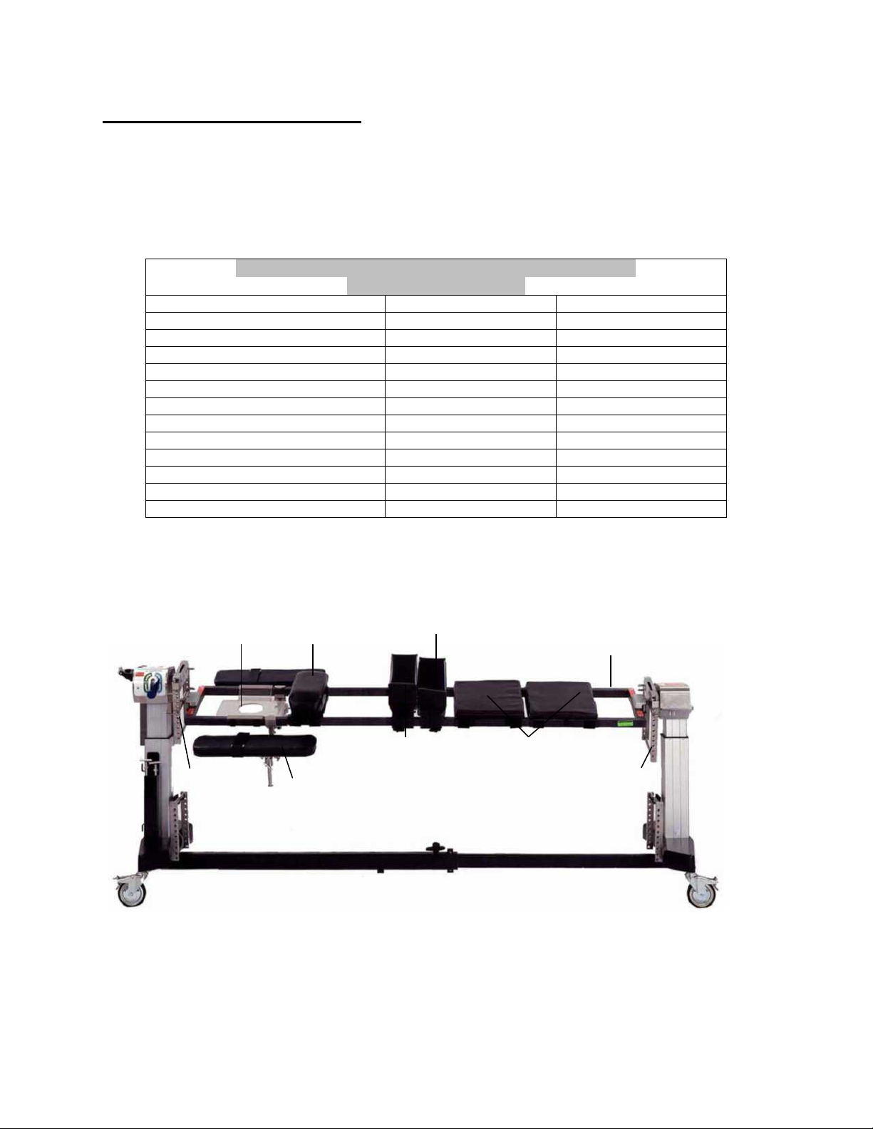
2.1 Jackson Spinal Surgery Top
The Jackson Spinal Surgery Top is 17” (43 cm) wide, 84” (213 cm) long, made from a
carbon composite material and has a patient weight limit of 500 pounds (226 kg). The
table top is labeled to indicate its patient weight limit. The Jackson Spinal Surgery Top
includes the following items as standard components (see Figure 1):
Small Hip Pad 2 2
Regular (Medium) Hip Pad 2 2
Large Hip Pad 4 2
Thigh Pad (Right/Left) 2 2
Chest Pad Assembly 1 1
Head Support Section (Face Plate) 1 1
Leg Support Section (Leg Boards) 2 2
Leg Sling 1 1
Buttock Strap 1 1
Safety Strap 60” 1 1
Safety Strap 90” 4 4
Articulatiing Arm Board 2 2
HEAD END
Head support (face plate)
H-frame
(The table top is shown coupled to the 5803 Advanced Control Modular Table System Base.)
5943 and 5943AP JACKSON SPINAL SURGERY TOPS
(Standard Components)
Components 5943 5943AP
Figure 1: 5943/5943AP Jackson spinal surgery tops (standard components)
Chest pad
Articulating arm boards (2)
Figure 2: 5943 Jackson spinal surgery top with components
Thigh pads (2)
Hip pads (2)
Support sections (leg boards)
Spinal surgery
H-frame
FOOT END
top
MIZUHOSI 2009 NW0504 Rev. D
7
Page 8
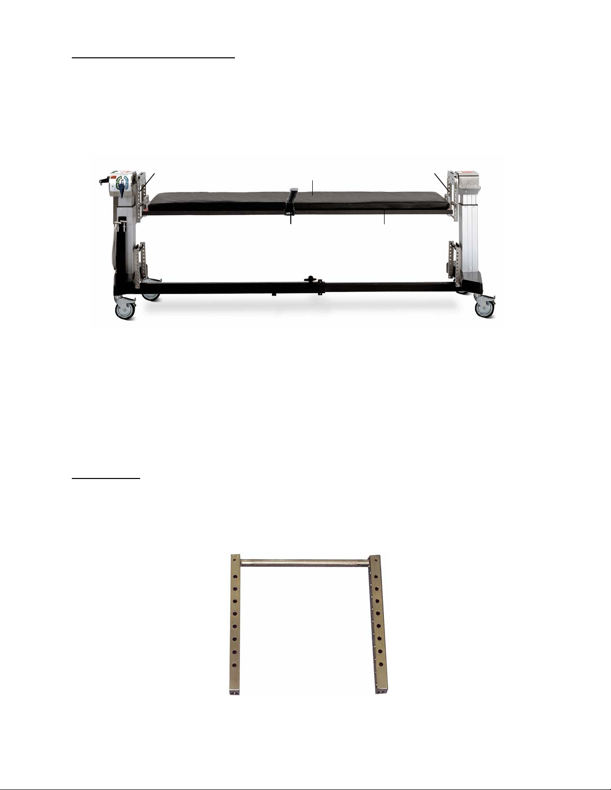
2.2 Radiolucent Imaging Top
The Radiolucent Imaging Top is 21.5” (54.6 cm) wide, 84” (213 cm) long, made from a
carbon composite material and has a patient weight limit of 500 pounds (226 kg). Each
Radiolucent Imaging Top is labeled to indicate its patient weight limit. The imaging top
is radiolucent including views through the radiolucent side rails. It includes a 2” thick
Mizuho OSI Tempur-Med® table pad and two (2) side rail mounted safety straps.
HEAD END
H-frame Table pad H-frame
FOOT END
Safety strap (2)
Radiolucent
imaging top
Figure 3: Radiolucent Imaging Top component identification
(The table top is shown coupled to the 5803 Advanced Control Modular Table System Base)
NOTE: Mizuho OSI P/N 5855-830 side rail adapters must always be used to attach
these types of devices to the table to prevent damage. If retractors, clark sockets, arm
boards or other accessories are attached directly to the side rail of the radiolucent
imaging top, they may cause damage in the form of cracking or splintering of the carbon
fiber table top. Please see section 3.0 in this owner’s manual for more information
related to the use of the Radiolucent Imaging Top.
2.3 H-Frame
Each Jackson Spinal Surgery Top and Radiolucent Imaging Top is supplied with two (2)
H-frames (see Figure 4). The H-frames are used to connect the table tops to the base
with T-pins. Four (4) H-frames are required to attach both table tops for a 180 degree
patient rotation (see section 8.0: Rotation Procedures).
Figure 4: H-Frame
MIZUHOSI 2009 NW0504 Rev. D
8
Page 9

2.4 T-Pin
Each Jackson Spinal Surgery Top and Radiolucent Imaging Top is supplied with four (4)
T-pins (see Figure 5). The T-pins are used to connect the H-frames to the crossbars on
the table base and to connect the table tops to the H-frames. Eight (8) T-pins are
required to attach both table tops for a 180 degree patient rotation (see section 8.0:
Rotation Procedures).
Drop lock
Figure 5: T-pin
2.5 Patient Safety Straps
The Jackson Spinal Surgery Top is supplied with six (6) patient safety straps; four (4)
90” straps, one (1) 60” strap, and one (1) buttock strap (see Figure 6). When a patient
is positioned on the Jackson Spinal Surgery Top or Radiolucent Imaging Top, verify that
the appropriate patient safety straps are applied and secured as described in section
7.0 of this owner’s manual.
Buttock strap
60"
90"
Figure 6: Jackson Spinal Surgery Top patient safety straps
2.6 Articulating Arm Board Assembly
The Jackson Spinal Surgery Top is supplied with two (2) articulating arm boards and
mounting brackets (see Figure 7). These arm boards may be attached directly to the
spinal top at any location along the length of the frame. The articulating arm board is
adjustable in six directions as shown by the arrows in Figure 7.
Armboard
assembly
Mounting
bracket
Figure 7: Articulating arm board for the Jackson Spinal Surgery Top
MIZUHOSI 2009 NW0504 Rev. D
9
Page 10
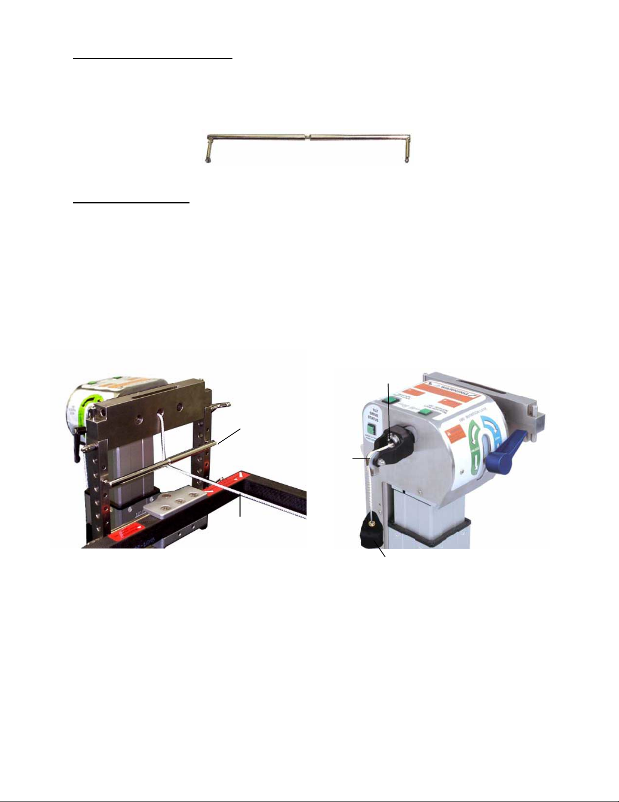
2.7 Cervical Traction Vector
The modular table base is equipped with a cervical traction vector (see Figure 8). The
cervical traction vector provides the adjustability of the angle of pull for cervical traction
as shown in Figure 9.
Figure 8: Cervical traction vector
2.8 Pulley Assembly
The pulley assembly is permanently attached to the head end column to guide a traction
rope. The cervical traction vector attaches to the medial side of the head end H-frame
in the mounting holes to achieve the desired angle of traction (see Figure 9). Sandbag
weights may be added to provide the appropriate traction load during anterior or
posterior cervical surgery or any other time cervical traction is desired. The traction
weight is connected to a rope, which passes over the pulley assembly, threads through
the pivot shaft of the head end crossbar and connects to the patient traction apparatus
(see Figure 10).
Cervical
traction
vector
Pulley
Traction rope
connecting to patient
traction apparatus
Pivot
shaft
Weight
Figure 9: Cervical traction vector installed in
H-frame.
Figure 10: Traction pulley assembly
NOTE: The amount of traction load applied to the patient is completely at the discretion
of the attending physician.
MIZUHOSI 2009 NW0504 Rev. D
10
Page 11
p
p
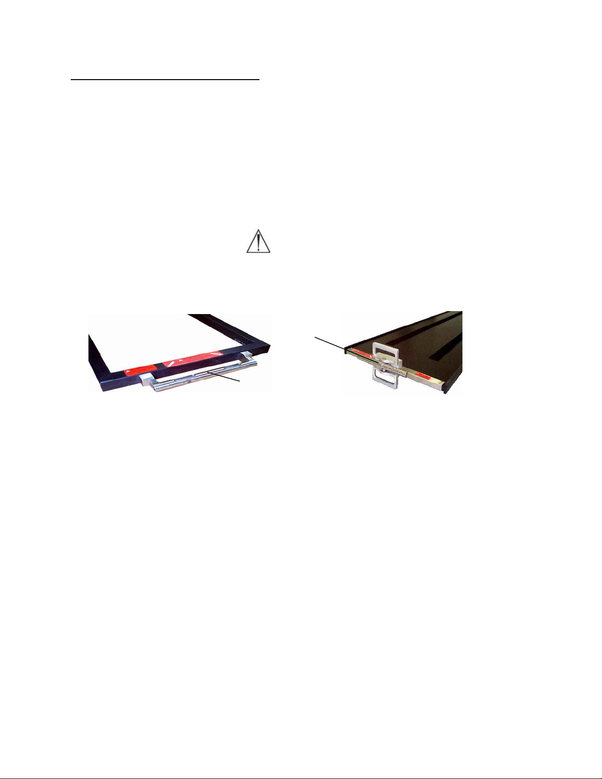
2.9 Coupling Device Identification
Identify the coupling device on the end of the table top (see Figures 11 and 12). Early
versions of the Jackson Spinal Surgery Top and Imaging Tops have fixed mounting
tubes. Jackson Spinal Surgery Tops built after October 1999 and Radiolucent Imaging
Table Tops built after January 1997 will have gimbal mounting assemblies (Figure 12).
Gimbals allow for rotation of the table top when positioned in extreme lateral tilt and
trendelenburg or reverse trendelenburg. Both designs couple to the H-frame in the
same fashion. The 5890/5891 Modular Table Bases can utilize either version of the
coupling devices but the 5892/5803 Advanced Control Bases must use only gimbal
mounting assemblies (Figure 12).
WARNING
:
Use of table tops on the 5892/5803 Advanced Control Bases without gimbal
mounting assemblies (Figure 12) can result in damage to the table top.
Gimbal mounting tube
Fixed mounting tube
Figure 11: Fixed mounting
tube on Jackson S
inal Surgery To
Figure 12: Gimbal mounting
assembly on Radiolucent Imaging Top
MIZUHOSI 2009 NW0504 Rev. D
11
Page 12
3.0 TABLE TOP COUPLING PROCEDURES
)
The Jackson Spinal Surgery Top and Radiolucent Imaging Top may be coupled and
interchanged to any modular table base, as needed, to provide flexibility and procedural
capability.
NOTE: For complete instructions on the modular table base operation and functions,
please refer to the appropriate owner’s manual supplied with the Modular Table Base.
A thorough understanding of the operation of the 5890 and 5891 Modular Table Base is
required before continuing.
3.1 5890/5891 Modular Table Bases
The following instructions are directed toward the use of a table top on the 5890 or 5891
Modular Table Base. These bases do not have the powered lateral tilt function.
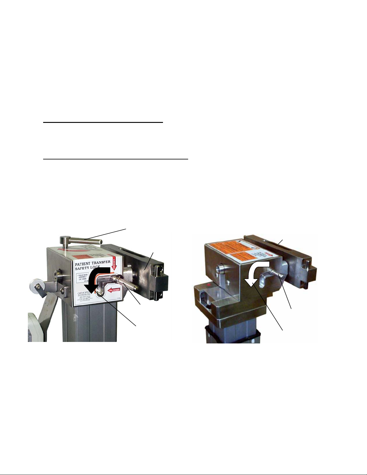
3.2 5890/5891 Patient Transfer Safety Lock
Each 5890/5891 Modular Base is equipped with a patient transfer safety lock at both the
head and foot end columns. The patient transfer safety lock is actuated by positioning
the lever protruding out of the right side of the control box at the head end column (see
Figure 13). A second patient transfer safety lock is located on the side of the foot end
control box (see Figure 14). When engaged, the patient transfer safety lock prevents
rotation of the crossbar by locking the crossbar in the horizontal position.
Rotational friction
control
Crossbar
Crossbar
Patient transfer
safety lock
Disengage
motion
Patient transfer
safety lock
Disengage
motion
Figure 13: Head end column (5890/5891 bases
shown
Figure 14: Foot end column (5890/5891 bases
shown)
MIZUHOSI 2009 NW0504 Rev. D
12
Page 13
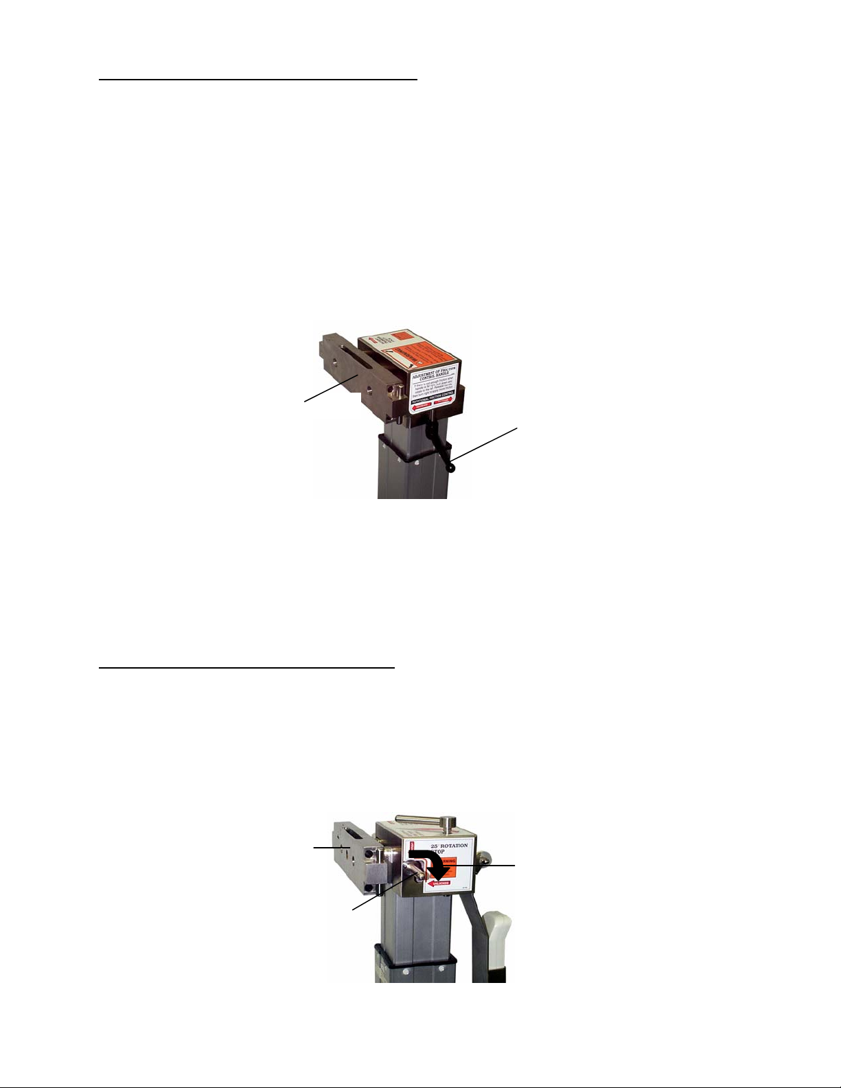
3.3 5890/5891 Rotational Friction Control
The rotational friction control is located at both the head and foot end columns. At the
head end, the rotation friction control is the large right-angled lever on top of the head
end control box (see Figure 13). At the foot end, the rotation friction control is the black
lever that is located on the lower side of the control box (see Figure 15). The rotation
friction control may be tightened to act as a friction brake or it can be adjusted to hold
the table top at any degree of lateral tilt. As a friction brake, it can be loosened to
maintain the desired amount of resistance while still allowing the table top to be
adjusted to a different degree of tilt. When completely loose, the rotation friction control
will facilitate 180 degree rotations. Rotate the rotation friction control clockwise to
increase friction and counterclockwise to reduce friction. It is recommended that the
rotation friction control be left in the maximum friction position (fully clockwise)
whenever table top movement is not intended.
Crossbar
Figure 15: Foot end column (5890/5891 base shown)
Rotation
friction
control
NOTE: Because the foot end rotation friction control lever has limited range of
movement, occasionally it may not be possible to fully loosen or tighten the brake with
one turn of the handle. In that case, once the end of the movement range has been
reached, pull the handle down. This will disengage the mechanism and allow the
handle to be returned to its starting position without affecting the amount of friction.
Repeat the process until the desired amount of friction is achieved.
3.4 Twenty-Five Degree Rotation Stop
Each modular base is equipped with a 25-degree rotation stop. The rotation stop
is actuated by the lever located on the left side of the control box near the top of
the head end column. It can be easily activated with the left hand when standing
at the head end of the table (see Figure 16). When engaged, the rotation stop
prevents lateral rotation greater than 25 degrees from the horizontal position.
The rotation stop should be left in the engaged position and disengaged only
during a 180-degree rotation.
Crossbar
Disengage motion
MIZUHOSI 2009 NW0504 Rev. D
25 Degree rotation stop
Figure 16: Head end column 25 degree rotation stop (5890/5891 base shown)
13
Page 14
p
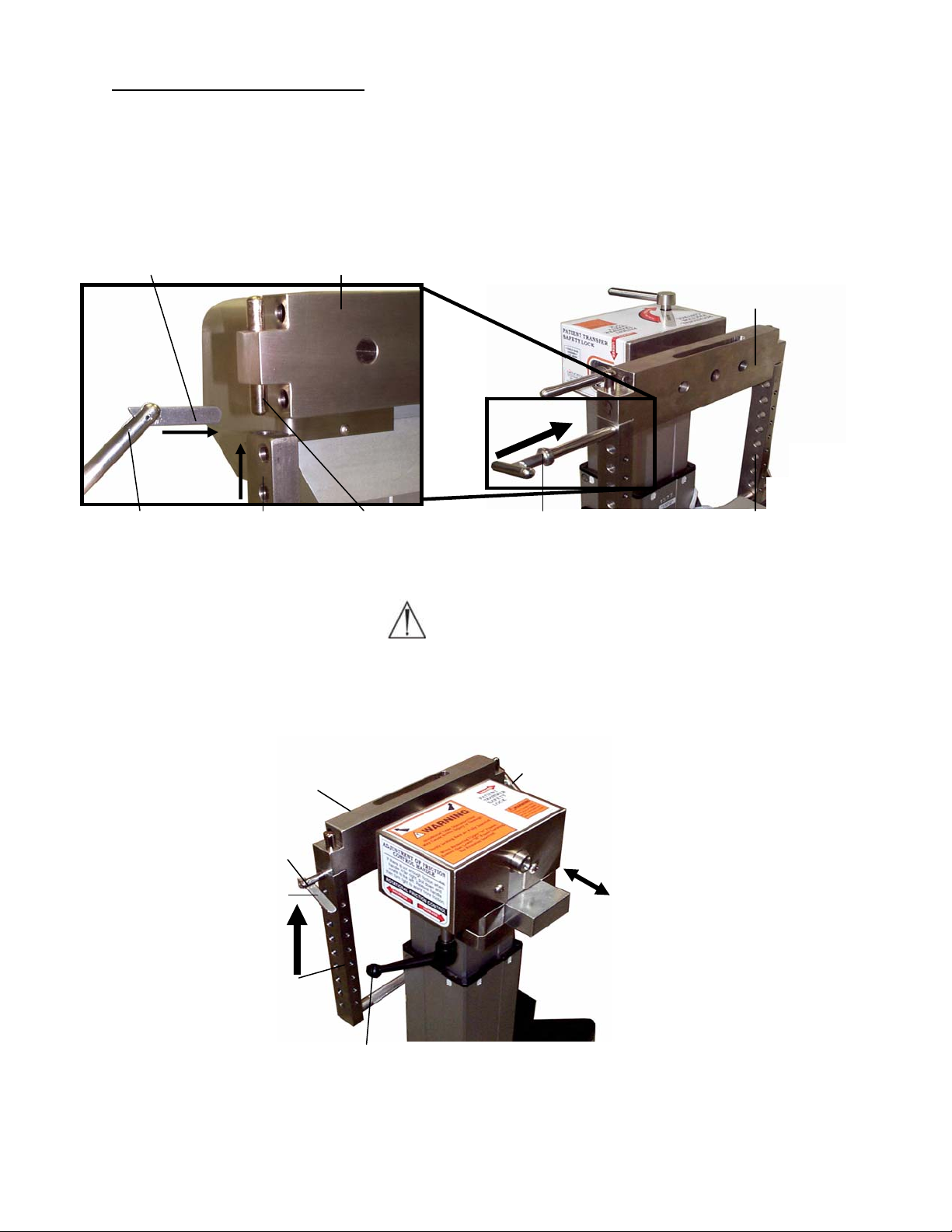
3.5 Installing The H- Frames
The following coupling procedure assumes the head end and foot end columns do not
have either the Jackson Spinal Surgery Top or the Radiolucent Imaging Top in place.
1. Lock the table base in position by engaging the (4) caster locks.
2. Install an H-frame to head end crossbar and secure with a T-pin (see Figures 17 and 18).
Drop lock
Crossbar
HEAD END
Crossbar
Figure 17: H-frame aligned with mounting stud
and T-pin prepared for insertion
H-frame T-pin
Mounting stud
T-pin
Figure 18: T-pin insertion into H-frame and
crossbar head end column
(5890/5891 base shown)
H-frame
WARNING:
Failure to install the T-pin will result in the patient and table assembly being dropped.
3. Install an H-frame to foot end crossbar and secure with a T-pin. Fully retract the foot
end crossbar by sliding it toward the foot end column (see Figure 19).
Drop lock
H-frame
T-
Crossbar
in
ON
T-pin
SLIDE
Rotation friction control
Figure 19: H-frame installed – foot end column (5890/5891 base shown)
MIZUHOSI 2009 NW0504 Rev. D
14
Page 15

4. Engage the patient transfer safety lock on the head end and foot end columns (see
Figures 13 and 14)
Warning:
For safe patient transfer, the patient transfer safety lock must be engaged prior to
transfer in order to prevent the possibility of the table top rotating while the
transfer occurs. Failure to do so may result in the patient being dropped.
5. Set the rotational friction control on the head and foot end columns to maximum
friction by fully rotating clockwise (see Figures 13 and 15).
6. Set the 25 degree rotation stop on the head end column (see Figure 16).
Warning:
Prior to coupling the table tops, verify that the two (2) H-frames are properly
installed to the crossbar. Confirm the T-pins passes completely through the Hframes and the crossbars and that the T-pin drop locks are in sight and pivot
freely. Failure to do so may result in the patient being dropped.
3.6 Selecting The Mounting Holes For The Table Top
When selecting the H-frame mounting hole, it is intended that the center of gravity of the
patient be at or below the centerline of the crossbars. For most patients, the fourth
open mounting hole below the crossbar is the appropriate position (see Figure 20).
Centerline of crossbars
Center of gravity of patient
Figure 20: Center of gravity axis of patient below the centerline of crossbars
NOTE: Two people are required to complete the following sequence of actions.
7. Select the appropriate mounting holes on the H-frame to support the table top.
Insert the T-pin into the H-frame on the head end column first. Align the mounting
tube on the table top to the selected mounting hole on the H-frame. Push the T-pin
through the H-frame, completely through the mounting tube and through the
opposite side of the H-frame. The T-pin drop lock should be in sight and pivot freely
(see Figure 21).
MIZUHOSI 2009 NW0504 Rev. D
15
Page 16

HEAD END
H-frame
Drop lock
Figure 21: Head end column with coupled Jackson Spinal Surgery Top
T-pin
Jackson Spinal
Surgery Top
Warning:
Verify that the T-pin is inserted through the H-frame, passes completely through
the table mounting tube and through the opposite side of the H-frame and that the
T-pin drop lock is in sight and pivots freely.
8. To couple the foot end of the table top, slide the H-frame and crossbar as necessary
to accommodate the length of the table top (see Figure 22). Align the mounting tube
on the table top to the selected hole on the foot end H-frame. Push the T-pin
through the H-frame, completely through the mounting tube on the table top and
through the opposite side of the H-frame. This should be done at the same level as
the mounting hole where the head end was coupled. The T-pin drop lock should be
visible and pivot freely.
Jackson Spinal
Surgery Top
H-frame
T-pin
Figure 22: Foot end column with coupled Jackson Spinal Top
FOOT END
Drop lock
MIZUHOSI 2009 NW0504 Rev. D
16
Page 17

Warning:
Failure to follow the above prescribed procedures regarding securing the H-frame
to the crossbars and the table top to the H-frames may result in the patient being
dropped.
Figure 23: Jackson Spinal Surgery Top coupled to 5890/5891 Modular Table Base
(shown without patient support pads)
3.7 5892/5803 Advanced Control Base
The Jackson Spinal Surgery Top and Radiolucent Imaging Top may be coupled and
interchanged to the 5892/5803 Advanced Control Base as needed to provide flexibility
and procedural capability. Identify the coupling device on the end of the table top as
described in section 2.9, Figures 11 and 12 of this manual.
Warning:
The Jackson Spinal Surgery or Radiolucent Imaging Tops used on the 5892/5803
Advanced Control Base must have gimbals (Figure 12). Earlier versions of these
table tops do not have gimbals. Use of table tops without gimbals can result in
damage to the table top.
NOTE: For complete instructions on the 5892/5803 Advanced Control Base operation
and functions, please refer to the appropriate owner’s manual supplied with the
advanced control base. A thorough understanding of the operation of the 5892/5803
advanced control base is required before continuing.
3.8 5892/5803 Table Control Identification
The head end of the 5892/5803 Advanced Control Base is equipped with three indicator
lights. These lights are: 1) 180° rotation lock indicator light, 2) tilt drive status light and 3)
rotation safety indicator light. Verify that the rotational safety lock switch is in the ON
position, and the 180 degree rotation lock lever is in the locked position. All three lights
must be illuminated before a patient is transferred to the table.
MIZUHOSI 2009 NW0504 Rev. D
17
Page 18
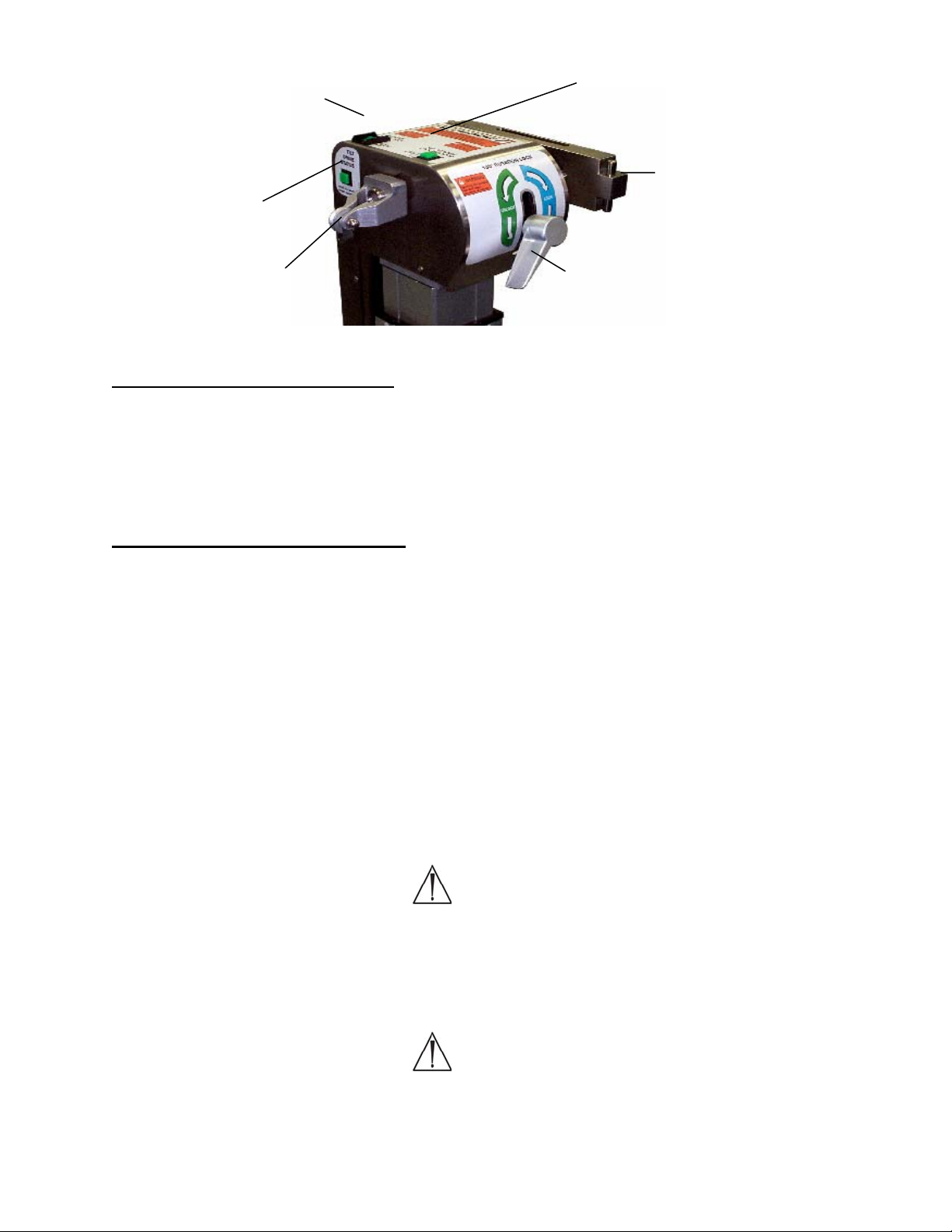
Rotation safety
lock switch / indicator
light
180° rotation lock
indicator light
Tilt drive status
indicator light
Crossbar
Traction pulley 180° rotation
lock lever
Figure 24: Indicator lights, head end column 5892/5803 Advanced Control Base
3.9 Rotation Safety Lock Switch
The rotation safety lock switch (with the lighted indicator) locks out the lateral tilt
function. This feature is designed to prevent unintended lateral tilt of the table top. The
rotation safety lock switch should be turned off only when a 180-degree patient rotation
is to be performed. If the rotation safety lock switch is not illuminated, press the rocker
switch to the ON position.
3.10 180° Rotation Lock Indicator
The 180° rotation lock indicator light, when lit, indicates the 180-degree rotation lock is
engaged and the table cannot be rotated 180 degrees. If the 180-degree rotation lock
indicator is not on, rotate the rotation lock lever clockwise until the light is illuminated.
NOTE: If a 180 degree patient rotation is to be performed, the rotation lock lever should
be rotated counterclockwise approximately one half rotation past the point that the
rotation lock indicator light goes out. Rotating the lock lever to this point lessens the
drag of the friction control, thereby allowing the table tops to rotate more freely during
the patient rotation. If even less friction is desired, the lock lever may be rotated further,
counterclockwise, as necessary.
After the patient rotation is complete, rotate the rotation lock lever clockwise until the
rotation lock indicator light is illuminated.
Warning:
When the rotation lock indicator light is not illuminated, the table top is
UNLOCKED regardless of how much the lock lever has been rotated clockwise or
counterclockwise. Always rotate the lock lever until the rotation lock Indicator
light is illuminated after a 180° rotation. If increased friction lock on the rotation
is required, rotate handle in a clockwise direction until desired friction is met.
Warning:
All three lights must be illuminated before a patient is transferred to the table. If
all three lights are not illuminated, do not transfer the patient until they are
illuminated.
MIZUHOSI 2009 NW0504 Rev. D
18
Page 19

3.11 Tilt Drive Status Indicator
The tilt drive status indicator light is lit when the power lateral tilt mechanism is in the
center position of the +/- 25 degree powered lateral tilt range. If the tilt drive indicator is
not illuminated, operate the lateral tilt function using the hand pendant in the appropriate
direction until the indicator is lit. The head end crossbar should be horizontal when the
tilt drive status indicator is lit. If the head end crossbar is not horizontal, the internal
power tilt mechanism is out of synchronization with the crossbar. Refer to the section
on synchronizing the lateral tilt function in the 5892 advanced control base user guide or
the 5803 owner’s manual, to reset this function.
3.12 Installing The H-Frames
The following coupling procedure assumes the head end and foot end columns do not
yet have either the Jackson Spinal Surgery Top or the Radiolucent Imaging Top in
place. The coupling procedure for the Jackson Spinal Surgery Top or the Radiolucent
Imaging Top is as follows:
1. Lock table base in position by engaging the (4) caster locks.
2. Install an H-frame to head end crossbar and secure with a T-pin (see Figure 25).
Fully retract the head end crossbar against the head end column.
3. Install an H-frame to foot end crossbar and secure with a T-pin (see Figure 26).
HEAD END
Sliding assembly
Crossbar
FOOT END
T-pin
Drop lock
Figure 25: H-frame installed - head end column
5892/5803 Advanced Control Base
ON
H-frame
ON
H-frame
Figure 26: H-frame installed – foot end column
5892/5803 Advanced Control Base
T-pin
MIZUHOSI 2009 NW0504 Rev. D
19
Page 20

3.13 Selecting The Mounting Holes For The Table Top
When selecting the H-frame mounting hole, it is intended that the center of gravity of the
patient be at or below the centerline of the crossbars. For most patients, the fourth
mounting hole below the crossbar is the appropriate position (see Figure 20).
NOTE: Two people are required to complete the following sequence.
4. Select the appropriate mounting holes on the H-frame to support the table top.
Insert the T-pin into the H-frame on the foot end column first. Align the mounting
tube on the table top to the selected mounting hole on the H-frame. Push the T-pin
through the H-frame, completely through the mounting tube and through the
opposite side of the H-frame. The T-pin drop lock should be visible and pivot freely
(see Figure 22).
Warning:
Verify that the T-pin is inserted through the H-frame, passes completely through
the table mounting tube, and through the opposite side of the H-frame and the Tpin drop lock is in sight and pivots freely. Failure to do so will result in the
patient and table assembly being dropped.
5. To couple the head end of the table top; slide the H-frame and crossbar away from
the foot end (shown in Figure 25) as necessary to accommodate the length of the
table top. Select the appropriate mounting holes on the H-frame to support the table
top. Align the mounting tube on the table top to the selected mounting hole on the
H-frame. Push the T-pin through the H-frame, completely through the mounting tube
and through the opposite side of the H-frame. This should be done at the same
level as the mounting hole where the head end was coupled. The T-pin drop lock
should be in sight and pivot freely (see Figure 21).
A table top completely coupled to a table base is shown in Figure 23.
Warning:
Failure to follow the above prescribed procedures regarding securing the H-frame
to the crossbars and the table top to the H-frames may result in the patient being
dropped.
MIZUHOSI 2009 NW0504 Rev. D
20
Page 21

4.0 IMAGING PROCEDURES
To perform most imaging procedures, attach the Radiolucent Imaging Top according to
the following procedure;
1. Lock the table base in position by engaging the (4) caster locks.
2. Verify that the table controls are locked.
4.1 5890/5891 Modular Table Bases
1. Engage the patient transfer safety locks at both the head and foot end columns (see
section 3.0, Figures 13 and 14).
2. Set the rotational friction control to maximum friction at both the head and foot end
columns (see section 3.0, Figures 13 and 15).
3. Engage the 25° rotation stop (see section 3.0, Figure 16).
4.2 5892/5803 Advanced Control Bases
1. Confirm the rotation safety lock switch is illuminated (see section 3. 0, Figure 24).
2. Confirm rotation lock indicator light is illuminated (see section 3.0, Figure 24).
3. Confirm the tilt drive status indicator is illuminated (see section 3.0, Figure 24).
4.2.1 Attach the Radiolucent Imaging Table Top with table pad (see section 3.0: Table
Top Coupling Procedures), depending on which base is used.
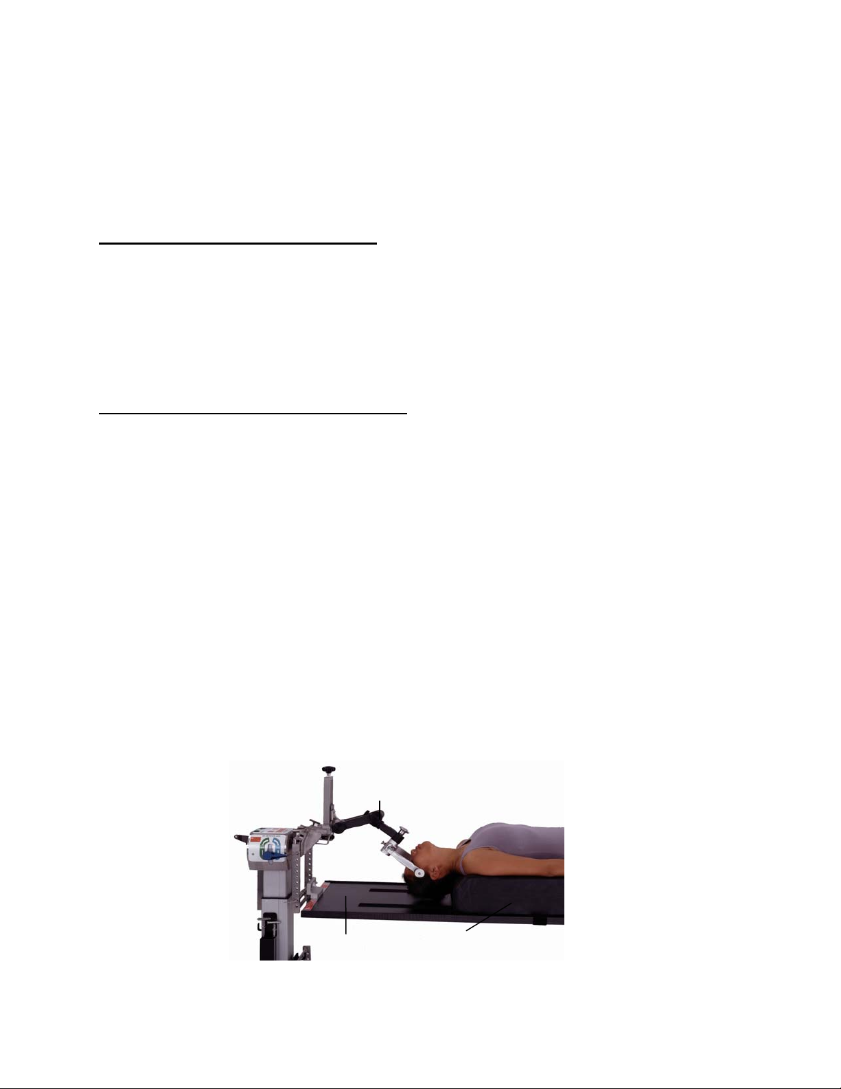
4.2.2 Transfer the patient in a supine position to the Radiolucent Imaging Top. Apply
the patient safety strap and secure.
Figure 27: Patient supine on the Radiolucent Imaging Top with pivoting arm boards
MIZUHOSI 2009 NW0504 Rev. D
21
Page 22

The radiolucent side rails are designed to support surgical arm boards. We recommend
Mizuho OSI P/N 5356 pivoting arm boards as shown in Figure 28. These should be
used in conjunction with P/N 5855-830 side rail adapters to prevent damage to the
imaging top side rails.
Pivoting
armboard
Imaging top
pad
Figure 28: Pivoting arm board with side rail adapter on the Radiolucent Imaging Top
P/N 5855-830
Side rail adapter
Imaging top
radiolucent side rail
MIZUHOSI 2009 NW0504 Rev. D
22
Page 23
5.0 SUPINE POSITIONING FOR ANTERIOR SPINE SURGERY AND PROCEDURES
The Radiolucent Imaging Top may be used for anterior spine procedures according to
the following procedure:
1. Lock the table base in position by engaging the (4) caster locks.
2. Verify that the table controls are locked.
5.1 5890/5891 Modular Table Bases
1. Engage the patient transfer safety locks at both the head and foot end columns (see
section 3.0, Figures 13 and 14).
2. Set the rotational friction controls to maximum friction at both the head and foot end
columns (see section 3.0, Figures 13 and 15).
3. Engage the 25° rotation stop (see section 3.0, Figure 16).
5.2 5892/5803 Advanced Control Bases
1. Confirm the rotation safety lock switch is illuminated (see section 3.0, Figure 24).
2. Confirm rotation lock indicator light is illuminated (see section 3.0, Figure 24).
3. Confirm the tilt drive status indicator is illuminated (see section 3.0, Figure 24).
5.2.1 Attach the Radiolucent Imaging Table Top with table pad or the 5879-2
Anterior Extension Positioner with 5” bladder (see section 3.0: Table Top
Coupling Procedures), depending on which base is used.
NOTE: For anterior cervical surgery where cervical spine extension is required, it is
recommended that the Mizuho OSI P/N 5879-2 Anterior Extension Positioner with 5”
bladder be used instead of the standard imaging top pad assembly (see Figure 29).
5.2.2 Transfer the patient to a supine position on the Radiolucent Imaging Table
Top. Apply the patient safety strap and secure.
5.2.3 The arms may be positioned parallel to the patient, tucked and s upported
with padding and a draw sheet.
Cervical management system
Figure 29: Patient table top with the optional anterior extension positioner and cervical management
system
MIZUHOSI 2009 NW0504 Rev. D
Imaging
top
Anterior extension positioner
23
Page 24
5.2.4 Prep and drape the patient in the standard fashion. This position provides
ideal access to the anterior cervical spine or ideal access to the anterior
lumbar spine through an abdominal approach which gives exposure to the
lumbar-sacral area. If the surgeon should desire to laterally rotate (tilt) the
patient, carefully follow the directions in section 8.0: Rotation Procedures,
depending on which base is used.
The option to perform surgery with the patient in cervical traction is readily available.
The Mizuho OSI P/N 5979-1 cervical management system is recommended for this
function (see Figure 29).
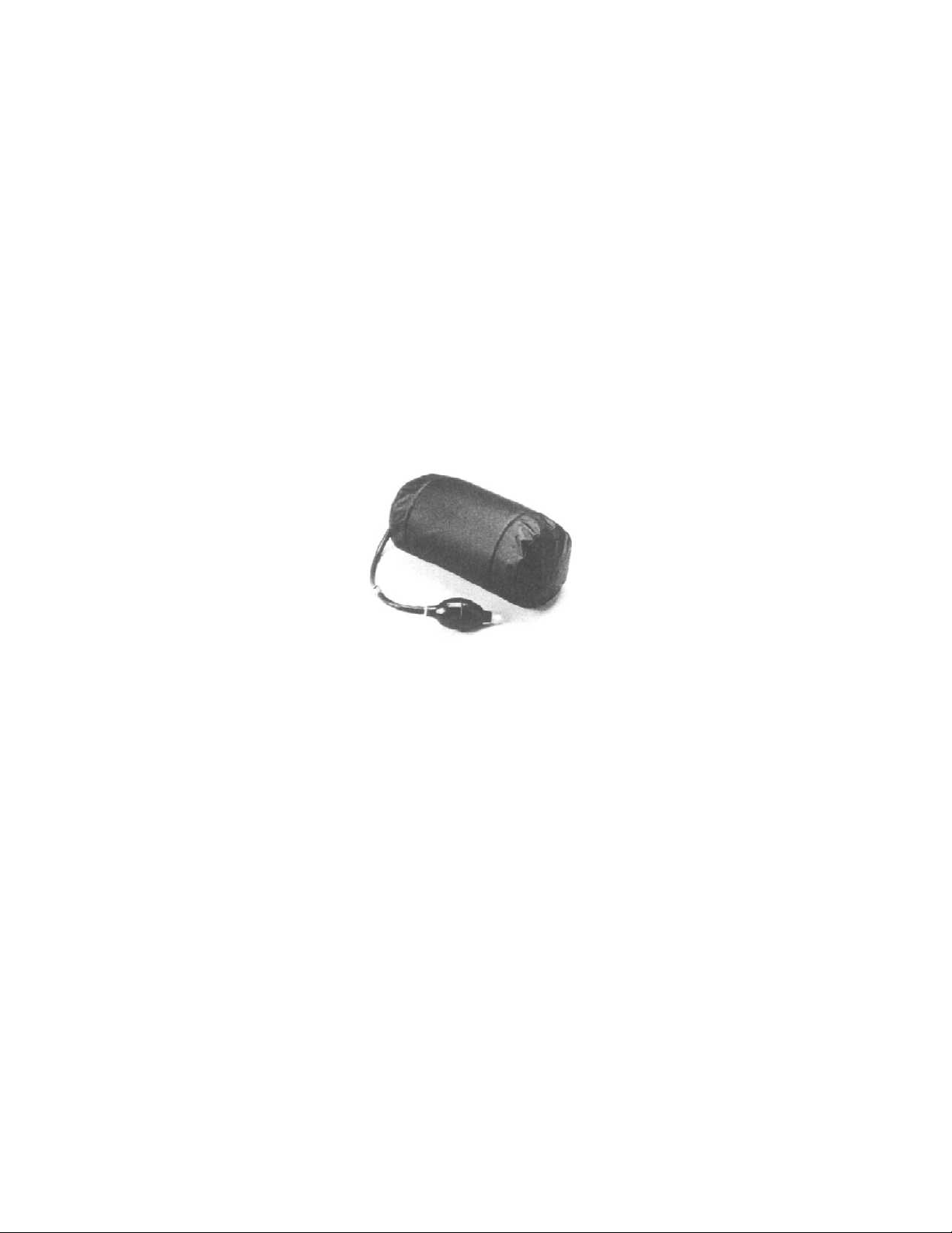
For anterior lower lumbar spine surgery, the Mizuho OSI P/N 973 or 974 inflatable
bladder may be used under the lower back to provide controlled lumbar spine
extension.
Upon completion of the anterior surgery, it is possible to rotate the patient to a prone
position while maintaining cervical traction and without having to remove the patient
from the table (see section 8.0: 180-degree patient rotation).
Figure 30: Inflatable bladder p/n: 973 (6”x 10”) and p/n: 974 (8”x10”)
MIZUHOSI 2009 NW0504 Rev. D
24
Page 25

6.0 LATERAL POSITIONING FOR LUMBAR & THORACIC SPINE SURGERY AND
PROCEDURES
A variety of surgical procedures in the lateral decubitus position may be performed on
the Radiolucent Imaging Top according to the following procedures:
1. Lock the table base in position by engaging the (4) caster locks.
2. Verify that the table controls are locked.
6.1 5890/5891 Modular Table Bases
1. Engage the patient transfer safety locks at both the head and foot end columns (see
section 3.0, Figures 13 and 14).
2. Set the rotational friction controls to maximum friction at both the head and foot end
columns (see section 3.0, Figures 13 and 15).
3. Engage the 25° rotation stop (see section 3, Figure 16).
6.2 5892/5803 Advanced Control Bases
1. Confirm the rotation safety lock switch is illuminated (see section 3.0, Figure 24).
2. Confirm rotation lock indicator light is illuminated (see section 3.0, Figure 24).
3. Confirm the tilt drive status indicator is illuminated (see section 3.0, Figure 24).
6.2.1 The Radiolucent Imaging Top should be coupled at the fifth or sixth
mounting hole below the centerline of the crossbar for lateral procedures
(see section 3.0, Figure 20).
Warning:
The Radiolucent Imaging Top must be coupled with the center of gravity of the
patient below the centerline of the crossbars when the patient is positioned
laterally. Failure to do so may make the patient unstable during lateral rotation
(see Figure 20).
6.2.2 Transfer the patient to a supine position on the Radiolucent Imaging Top;
apply a patient safety strap and secure.
6.2.3 Roll the patient on his or her side. Stabilize and maintain the patient in the
lateral decubitus position by means of at least two (2) patient safety straps
or a lateral positioning device such as the Mizuho OSI P/N 5300 Lateral
Positioner or the Mizuho OSI P/N 5301 Deluxe Lateral Positioner (see
Figure 31). You may wish to use standard positioning aids, e.g., pillows,
an axillary roll and foam or gel padding for additional patient stability and
comfort.
MIZUHOSI 2009 NW0504 Rev. D
25
Page 26

Imaging top as viewed from above
Lateral
positioners
Figure 31: Mizuho OSI P/N 5300 Lateral Positioner on Radiolucent Imaging Top
6.2.4 The patient may be laterally rotated to a maximum of 25° in each direction. To
do so, use the appropriate table base controls. Do not release the 25° rotation
stop or attempt to rotate the patient in the lateral position more than 25
degrees.
Warning:
The 25° rotational stop must always be engaged when using the Radiolucent
Imaging Top for lateral positioning. Lateral rotation of a patient in the lateral
position to more than 25° may result in the patient being dropped.
NOTE: If increased stability in the lateral position is desired or if more than 25° of
lateral rotation is required for thoracic surgery; we recommend the use of the Mizuho
OSI 5895 Maximum Access™ Lateral Top (see Figure 32). This top is also used for
simultaneous anterior/posterior lumbar surgery. Contact your Mizuho OSI
representative for more information regarding this product.
MIZUHOSI 2009 NW0504 Rev. D
26
Page 27
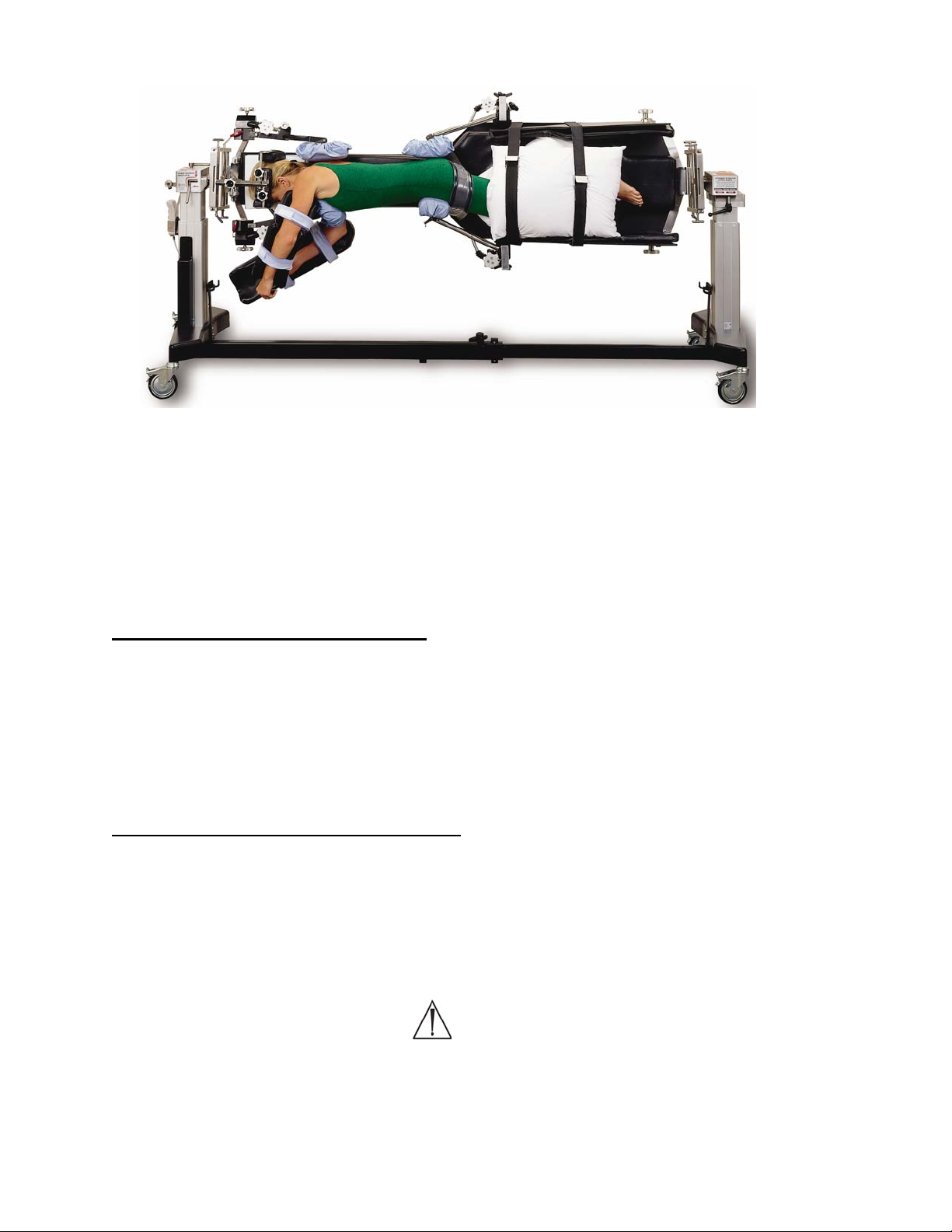
Figure 32: P/N 5895 Maximum Access™ Lateral Top
7.0 PRONE POSITIONING FOR POSTERIOR SPINE SURGERY AND PROCEDURES
The Jackson Spinal Surgery Top can be used for prone procedures according to the
following procedure:
1. Lock the table base in position by engaging the (4) caster locks.
2. Verify that the table controls are locked.
7.1 5890/5891 Modular Table Bases
1. Engage the patient transfer safety locks at both the head and foot end columns (see
section 3.0, Figures 13 and 14).
2. Set the rotational friction controls to maximum friction at both the head and foot end
columns (see section 3.0, Figures 13 and 15).
3. Engage the 25° rotation stop (see section 3, Figure 16).
7.2 5892/5803 Advanced Control Bases
1. Confirm the rotation safety lock switch is illuminated (see section 3.0, Figure 24).
2. Confirm rotation lock indicator light is illuminated (see section 3.0, Figure 24).
3. Confirm the tilt drive status indicator is illuminated (see section 3.0, Figure 24).
7.2.1 Attach the Jackson Spinal Surgery Top (see section 3.0: Table Top Coupling
Procedures).
Warning:
The Jackson Spinal Surgery Top must be coupled with the center of gravity of the
patient at or below the centerline of the crossbars when the patient is prone.
Failure to do so may make the patient unstable during lateral rotation (see Figure
20).
MIZUHOSI 2009 NW0504 Rev. D
27
Page 28

7.2.2 Open the patient care kit. The patient care kit is intended for SINGLE PATIENT
USE ONLY. When using a GentleTouch® Pillow, it is recommended to open the
pillow at least 20 minutes prior to use, in order to allow for complete expansion
of the pillow.
7.3 5943AP Jackson Spinal Surgery Top with Advanced Control Pad System
The 5996 Advanced Control Pad System™ (ACP) with TEMPUR-MED® is designed
specifically for use with the Jackson Spinal Top. Utilizing the ACP System, automatic
massage action and periodic pressure point stimulation is provided to the patient at the
site of the hip and thigh pads. The ACP System consists of three components that work
together:
1. 5996-5 Variable cycle controller 100-120 VAC or 5996-6 Variable cycle controller230 VAC
2. 5996-200 Mizuho OSI TEMPUR-MED® patient support pads
3. 5996-12 ACP Quick connect tubing
The ACP System is an electronically controlled, pneumatically actuated system with a
rating of IPX-4 waterproof rating. It operates at either 100-120V-AC, 50/60hz or at
230V-AC, 50hz. Refer to the 5996 Advanced Control Pad System user guide
(NW0491) for complete set-up and use instructions.
7.4 Patient Support Pad Operation
The patient support pads attach to the Jackson Spinal Surgery Top using the lock lever
on the pad base. To attach, slip the pad base over the frame of the spinal top and
rotate the lever to lock as shown in Figures 33 and 34.
Pad support
Jackson spinal
surgery top frame
Clamp post
Rotate to
lock
Clamp post
Jackson spinal
surgery top frame
Lock lever
Lock lever
Figure 33: Unlocked position
(Support pad shown from below)
Figure 34: Locked position
MIZUHOSI 2009 NW0504 Rev. D
28
Page 29
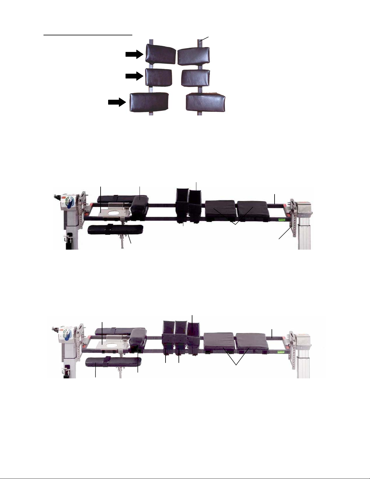
7.5 Selection Of Hip Pads
(
Small
Regular
medium)
Large
Figure 35: Identification of available hip pads
7.5.1 For patients under 350 pounds; determine which hip pad set (small,
regular or large) will be used, according to the size of the patient. Once
installed, confirm that the pad locking levers latch securely.
HEAD END
Head support (face plate)
Chest pad
Figure 36: Table pad set-up for a patient up to 350 pounds
For 350 to 500 pound patients it may be necessary to: use four (4) large hip pads
in conjunction with two (2) thigh pads and one (1) chest pad (see Figure 37).
Once installed, confirm that the pad locking levers latch securely.
Head support
(face plate)
Articulating arm
boards
Figure 37: Table pad set-up for a patient of 350 to 500 pounds
Chest pad
7.5.2 Attach the appropriate patient support pads onto the Jackson Spinal
Surgery Top. Lock the pads in place by rotating the locking lever onto the
clamp post. Once installed, confirm that the pad locking levers latch
securely (see Figures 33 and 34).
Thigh pads (2)
Hip pads (2)
Articulating arm boards
Thigh pads (2)
Large hip
pads (4)
Jackson spinal top
FOOT END
Spinal surgery
top frame
Leg supports
H-frame
Spinal surgery
top frame
Leg supports
MIZUHOSI 2009 NW0504 Rev. D
29
Page 30

NOTE: In order to achieve the correct and final position of the pads, it may be
necessary to reposition the pads along the table frame after a patient has been
transferred. To do so, carefully lift the patient, release the pad locking lever; slide and
relocate the pad to the designed position and re-engage the locking lever.
Warning:
Verify that the pad locking levers are latched securely in place. Failure to do so
may result in the pad bases breaking when the patient is being transferred on or
off the Jackson Spinal Surgery Top.
7.5.3 Apply the GentleTouch® face pillow, chest, hip and thigh pad covers as
described in the patient care kit instructions.
7.5.4 Attach either the two leg support sections or the leg sling to the table top.
The leg support sections are shown in Figures 36 and 37; the sling is
shown in Figure 38.
7.6 Use Of The Leg Sling
The leg sling may be used to support the legs on the Jackson Spinal Surgery Top in
place of the leg support sections (see Figure 38). The leg sling can allow for increased
hip flexion by allowing the patient’s knees to be lowered below the frame of the Jackson
Spinal Surgery Top. When the sling is used, it is recommended not to use the thigh
pads as the increased hip flexion angle may increase the pressure on the anterior
aspect of the thighs. A patient properly positioned in a leg sling is shown in Figure 43.
Figure 38: Leg sling
The sling should be adjusted for each patient. The straps on the sling consist of a
double-sided hook closure that allows for infinite adjustment along the length of the
strap. To install the sling, place the sling over the frame of the foot end of the spinal top.
Feed the four straps through their respective buckles on the opposite side of the sling
and secure. The hook end of the strap may be folded over onto the loop portion of the
strap to allow for greater adjustability. The strap may be folded over itself again to
shorten it, thereby raising the sling and decreasing the hip flexion angle of the patient.
7.6.1 Place two (2) or three (3) pillows in the leg sling approximately where the
patient’s lower legs will rest to help achieve the desired amount of knee
flexion. This can also be done when using the leg support sections.
MIZUHOSI 2009 NW0504 Rev. D
30
Page 31

7.7 Selection Of Head Support Method
7.7.1 Prior to the patient transfer, the surgeon should select the desired method
of support for the patient’s head. The chosen method determines the next
step of preparation.
Five (5) options are available:
OPTION #1 Support the patient’s head using a GentleTouch
®
pillow, such as the one
provided in the patient care kit (Mizuho OSI P/N 5808), in conjunction with
the head support plate. This pillow is available separately as (Mizuho OSI
P/N 1937 or 1927) (see Figure 39). Once removed from the patient care
kit, this pillow requires 20 minutes for complete expansion.
GentleTouch ® pillow
Figure 39: GentleTouch® prone pillow
OPTION #2 Use skull tongs or horseshoe headrest in conjunction with the Mizuho OSI
(5979-1) Cervical Management Base Unit (see Figure 40).
Cervical Management Base Unit
Skull tongs
Figure 40: Skull tongs attached to the Cervical Management Base Unit
MIZUHOSI 2009 NW0504 Rev. D
31
Page 32

OPTION #3 Use a head halter. Apply the traction cord to the head halter through the
pulley assembly at the head end of the table (see Figure 41). Using
sandbags, apply the desired amount of weight on a weight carrier at the
head end of the table.
Head halter
Sandbag
weight
Figure 41: Head halter traction
OPTION #4 Use gardner wells tongs applied to the patient’s skull in accordance with
the manufacturers instructions. Apply traction cord to the tongs through
the pulley assembly at the head end of the table. Using sandbags, apply
the desired amount of weight on a weight carrier at the head end of the
table.
OPTION #5 If the patient is fitted with a cervical halo, it is possible to attach some
halos directly to the Mizuho OSI Cervical Management Base Unit (see
Figure 42). Consult with the halo manufacturer for the availability and use
of halo adapters.
Figure 42: Halo device attached to the Cervical Management Base Unit
Halo device
Halo adapter
Cervical Management Base Unit
Warning:
The halo, tongs or horseshoe devices should only be used in accordance with the
specific manufacturer’s recommended procedures.
MIZUHOSI 2009 NW0504 Rev. D
32
Page 33

NOTE: It is recommended to apply anti-embolism stockings and sequential
compression stockings to the patient in the prone position prior to surgery to promote
venous return and reduce the potential of pedal edema. This should be done at the
direction of the attending physician and according to the manufacturer’s
recommendations.
7.8 Transferring The Patient
7.8.1 Position the patient transport stretcher with the patient parallel to the
Jackson Spinal Surgery Top. The support pads should be adjusted to the
approximate location to the anatomical landmarks prior to transferring the
patient, i.e., the iliac crest aligned to the center of the hip pad (Figure 42).
7.8.2 To facilitate the patient transfer, raise the patient transport stretcher so that
it is approximately level with the top of the support pads.
7.8.3 Roll the patient onto the Jackson Spinal Surgery Top into the prone position
while supporting the head, torso and legs during the transfer.
7.9 Positioning Of The Head
7.9.1 Support the patient’s head securely using one of the five options detailed in
section 7.7.
7.10 Positioning Of The Arms
7.10.1 Attach the articulating arm boards to the Jackson Spinal Surgery Top. The
mounting bracket of the arm board may be positioned above or below the
head support plate; position the arm board parallel to the table top (see
Figure 36).
7.10.2 Place the arms in the TLC arm cradles provided in the patient care kit.
Position the arms on the articulating arm boards and secure with the contact
closure straps provided. The arms should be flexed at the shoulders no
greater than 90 degrees and at the elbows no greater than 90 degrees (see
Figure 43).
Warning:
Hyperextension of the shoulder may cause compression of the brachial plexus
resulting in a potential nerve or vascular injury.
7.11 Positioning Of The Chest
7.11.1 The chest pad should contact the patient so the top edge of the chest pad is
at the patient’s supra-sternal notch. With ideal positioning, the chest pad
should contact the patient so the load is borne predominantly by the
superior aspect of the chest on the sternum. This position will also protect
the breasts and muscles from bearing the primary load of the upper torso.
When the chest is positioned in such a manner, proper patient ventilation is
facilitated. To reposition the chest pad with a patient on the table, slightly lift
the patient and slide the pad along the frame until the desired location is
achieved. Gently lower the patient back onto the pad. Confirm the chest
pad cover is in the proper position without fold or creases.
MIZUHOSI 2009 NW0504 Rev. D
33
Page 34

Warning:
Positioning of the chest pad superior to the supra-sternal notch may apply
pressure to the throat and patient’s airway.
7.12 Positioning Of The Hips And Thighs
7.12.1 Adjust the hip pads to rest under the iliac crests. The iliac crests should
be centered on the hip pads (see Figure 43).
Iliac crest centered on hip pad
Buttock strap
Pillows
Safety strap
Safety strap
Leg sling
Figure 43: Patient prone in the spinal surgery top with the leg sling
Pillows Buttock strap
Figure 44: Patient positioned prone on spinal surgery top using leg support sections
Safety strap Safety strap
NOTE: The thigh pads are designed to be right and left sided and are labeled
accordingly. The pads must be oriented toward the patient when the patient is
positioned prone on them. The thigh pads have a compound angle, which provides for
anatomical support of the legs. Confirm the pads are applied to the appropriate side of
the spinal surgery top. When properly installed, the pads should slope down toward the
foot end of the table.
MIZUHOSI 2009 NW0504 Rev. D
34
Page 35

7.12.2 The thigh pads should contact the distal edge of the hip pads and should rest
under the patient’s thighs (see Figure 36). Once the pads have been adjusted
to the proper location, the surgeon should gently lift the patient at the location of
contact for each pad and smooth the contact surface of the pad.
7.12.3 Confirm that all support pad locks are latched and secure.
7.13 Positioning Of The Legs
7.13.1 Position the legs on the leg support sections or the leg sling as desired. When
using the sling, place two (2) or three (3) pillows below the patient’s knees and
tibias to aid in minimizing the pressure on the knees and tibias. Confirm that
the patient’s feet are free from contact of any table surface.
NOTE: It may be advantageous to use the leg sling to accommodate a tall patient on
the spinal top by allowing increased hip and knee flexion.
7.13.2 Place a blanket over the feet up to the gluteal area to assist in decreasing the
potential of hypothermia. Extra pillows may be positioned under the feet and
lower legs to prevent the feet from contacting the top or base and to increase
the knee flexion angle.
NOTE: Due to the open nature of the Jackson Spinal Surgery Top and the long
duration of the spinal surgical procedure, the use of forced air warmers, fluid warmers
and blankets should be considered and are recommended to help prevent hypothermia.
Blankets may be placed over the feet up to the gluteal area and across the shoulders
and arms out of the surgical field to aid in maintaining the patient’s body temperature.
These devices should be used according to the manufacturer’s directions and at the
direction of the attending physician.
7.13.3 Apply the buttock strap across the lower gluteal area. This strap should be
positioned cephalad of the hip pads around the table frame and back into the
corresponding buckle. Confirm the buttock strap is positioned low on the
gluteal area, surrounds both hip pads, and is secured snugly around the
buttocks. The blanket may be used under the buttock strap to protect the
patient from direct contact with the safety strap.
7.13.4 Apply a safety strap (60”) across the patient’s calves and around the frame and
secure with the buckle. The strap should be tight enough to secure the legs
against the pillows if the Table is laterally tilted. Apply a safety strap (90”)
around the patient’s torso, chest pad and table and secure with the buckle (see
Figure 43).
7.13.5 Prep and drape the patient in the standard fashion. Avoid the prepping solution
from flowing and pooling below the patient’s abdomen and onto the
components of the table.
7.13.6 If desired, the surgeon can adjust table height, trendelenburg and reverse
trendelenburg with the patient in place by using the hand pendant. (The lateral
tilt can be adjusted using the hand pendant on the 5892/5803 Advanced
Control Base only.) Refer to the appropriate Modular Table Base owner’s
manual for complete instructions for using these functions.
MIZUHOSI 2009 NW0504 Rev. D
35
Page 36

8.0 ROTATION PROCEDURES
The Jackson Spinal Surgery Table’s unique design allows the surgeon to rotate the
patient safely about the horizontal axis. This rotational capability provides many unique
advantages including specific imaging techniques previously unavailable. This includes
the ability to perform a 360 degree rotation without removing the patient from the table,
accomplishing the anterior and posterior surgical procedures during a single operating
room visit.
8.1 Intra-Operative Lateral Rotation or Lateral Tilt
In order to laterally rotate a patient with the C-arm in place and while under flouroscopy,
the following steps must be followed:
8.1.1 Secure the patient to the table as specified in section 5.0: Supine
Positioning for Anterior Spine Surgery or section 7.0: Prone Positioning
for Posterior Spine Surgery and Procedures.
Warning:
It is not recommended to laterally rotate the patient more than 25 degrees without
a thoracic and lower extremity safety strap in place. Laterally rotating a patient
more than 25 degrees without the safety straps may result in the patient being
dropped.
Warning:
The patient should not be laterally rotated more than 25 degrees unless the
Mizuho OSI Maximum Access™ Lateral Top is used.
8.2 5890/5891 Modular Table Bases
1. Confirm that the (4) caster locks on the modular base are engaged.
2. Confirm that the 25 degrees rotation stop is engaged.
MIZUHOSI 2009 NW0504 Rev. D
36
Page 37

3. Confirm rotational friction controls are in the maximum friction position. Standing at
one side of the table, firmly grasp both sides of the table to prevent undesired
rotation due to asymmetric patient loading.
4. Disengage the patient transfer safety locks at the head and foot end. (It may be
necessary to slightly release the rotational friction controls at both the head and foot
end to disengage the patient transfer safety locks).
5. Release the rotational fricti on controls at the head and foot end until the table can be
moved. Rotate the table top until the desired X-ray view is attained.
6. Tighten the rotational friction controls at both the head end, and foot end.
8.3 5892/5803 Advanced Control Bases
1. Confirm that the (4) caster locks on the modular base are engaged.
2. Confirm the rotation safety lock switch is illuminated.
3. Confirm the 180 degree rotation lock lever is in the locked position.
4. An attendant at the head of the bed should press the appropriate right or left tilt
button on the hand control pendant to laterally rotate the table top until the desired xray view is attained.
NOTE: The tilt drive indicator on the 5892/5803 base will not be illuminated once the
table is laterally rotated away from its neutral position.
Warning:
Failure to follow the prescribed procedures regarding the use of controls, locks
and patient safety straps may result in the patient being dropped.
8.4 180-Degree Patient Rotation
The 180-degree patient rotation sequence is designed to allow a patient to be rotated
completely from the supine to the prone position or visa versa. This may only be
accomplished after the positioning sequence described in section 5.0: Supine
Positioning for Anterior Spine Surgery and Procedures is completed. In most instances,
the patient will be repositioned for posterior spine surgery after the anterior spine
surgery has been completed (i.e. rotated from a supine position to a prone position).
The following 180-degree patient rotation repositioning process assumes the patient is
initially positioned supine on the radiolucent imaging top. This rotation procedure will
result in the patient positioned prone on the Jackson Spinal Surgery Top.
Figure 45: Patient supine on the imaging top
MIZUHOSI 2009 NW0504 Rev. D
37
Page 38

NOTE: This procedure requires at least two people to attach the table tops and rotate
the patient and one person to monitor or stabilize the head during rotation.
8.5 Preparation For Rotation
8.5.1 The patient’s head should be immobilized by means of skull traction or
with pillows and straps. The patient’s head must be supported before,
during and after the 180-degree rotation.
8.5.2 If using leg boards on the spinal top during rotation, place two to three
pillows on the patient’s knees and tibias. If rotating using the leg
suspension sling, place three pillows under the patient’s knees, and two to
three pillows on top of the patient’s knees and tibias.
8.5.3 Attach an upper H-frame to head end crossbar mounting stud and secure
with a T-pin (see Figure 46).
Head end column crossbar
Upper H-frame
Mounting stud
Lower T-pin
Lower H-frame
Figure 46: Upper H-frame prepared for mounting to crossbar (5890 base shown)
8.5.4 The spinal surgery top should be held stable by two attendants; one at each
end of the table. Attach the spinal top in the uppermost mounting hole of the
H-frame above the crossbar on the head end and secure with a T-pin.
8.5.5 The attendant at the foot end of the table must raise the foot end of the
spinal top so that the pads do not contact the patient. At this point, the
attendant can adjust the position of the chest, hip, thigh pads and leg
support to ensure proper placement when the patient is rotated. The
support pads should be positioned on the spinal top according to the
landmarks instructed in section 7.0 Prone Positioning for Posterior Spine
Surgery and Procedures. Confirm the support pads are locked and secure.
8.5.6 Attach an H-frame to the foot end crossbar while surrounding the table top
coupling tube and secure with a T-pin. Attach the spinal top to the
uppermost mounting hole of the H-frame above the foot end crossbar and
secure with a T-pin.
8.5.7 Position the patient’s arms parallel to the body and tuck in place with a draw
sheet. Remove any arm boards from the Radiolucent Imaging Top.
MIZUHOSI 2009 NW0504 Rev. D
38
Page 39

8.5.8 Apply the four (4) 90” safety straps around both frames and secure one at
the chest pad, one between the hip and thigh pads at the hips, and one at
the knees and one at the feet. For ease of access, all buckles should be
placed on the same side of the table (see Figure 47).
1
2
3
4
Iliac crests centered over hip pad
5
6
7
8
1
2 3 4
=T-pin count =Safety strap count
Figure 47: The Jackson Spinal Surgery Top positioned over the patient with unsecured safety
straps in position prior to compression
8.5.9 Fill the void between the patient’s legs and spinal tops with additional
pillows as necessary to support the patient’s legs during the rotation (see
Figure 48).
1
2
5
6
3
7
4
8
1 2 3 4
=T-Pin count =Safety strap count
Figure 48: Jackson Spinal Surgery Top in position over patient on imaging top with safety straps
in place.
8.6 Compression Sequence
NOTE: It is intended that the following sequence be performed rapidly to prevent
extended compression of the patient. When properly executed, the compression,
rotation and release sequence should take less than thirty seconds. This is desirable to
avoid undue extended compression of the patient.
MIZUHOSI 2009 NW0504 Rev. D
39
Page 40

8.6.1 Release the spinal surgery top from the upper most mounting hole of the
head end H-frame. Lower the spinal top until the weight of the top rests
on the patient. The primary contact is usually the chest pad on the
patient’s sternum. Couple the spinal surgery top at this level to the head
end H-frame with a T-pin (see Figure 49).
8.6.2 Release the spinal surgery top from the foot end H-frame. Lower the foot
end of the spinal surgery top until the hip pads contact and rest against
the patient’s iliac crests. The thigh pads should compress lightly against
the patient’s legs. Couple the spinal surgery top at the mounting hole
nearest this level to the foot end H-frame by using a T-pin (see Figure 49).
NOTE: Assess the compression of the patient at the chest and iliac crests.
8.6.3 Tighten the four (4) safety straps now that the patient is compressed.
8.6.4 Count to verify that all T-pins are in their locked position; four (4) each at
the head and foot ends for a total of eight (8) T-pins. Count to verify that
the four (4) safety straps are secure and in their proper position (see
Figure 49).
Warning:
Prior to rotation, verify that all H-frames and T-pins are fully engaged and in the
locked position. Failure to follow the prescribed procedures regarding securing
T-pins and the use of patient safety straps may result in the patient being
dropped.
NOTE: The Anesthesiologist may choose to disconnect the patient’s intravenous
infusions, monitoring devices and anesthesia circuit prior to the 180-degree rotation. If
not, these lines must be observed and controlled during the rotation.
1
2
3
4
Figure 49: Patient compressed and ready for 180 degree rotation
1 2 3 4
=T-Pin count =Safety strap count
COMPRESSION
5
6
7
8
8.6.5 The attendant rotating the patient should be stationed near the patient’s waist and
must firmly grip both table tops.
MIZUHOSI 2009 NW0504 Rev. D
40
Page 41

8.7 Rotation Procedure For The 5890/5891 Modular Table Bases
With an attendant at both ends of the table:
1. Release the rotational friction controls.
2. Disengage the patient transfer safety locks at both the head and foot end columns.
3. Disengage the 25-degree rotation stop at the head end column.
4. Rotate the patient.
NOTE: The attendant performing the rotation must rotate the table tops and patient 180
degrees toward himself or herself without stopping until the complete 180 degree
rotation is achieved.
Warning:
Once the rotation has started, do not stop until the patient has been rotated to the
full 180 degrees.
After the rotation:
1. Immediately engage the patient transfer safety locks.
2. Engage the 25-degree rotation stop.
3. Tighten the rotational friction controls to maximum friction.
NOTE: The attendant performing the rotation may now release the table tops. The
patient is now repositioned on the spinal surgery top in the prone position (see Figure
50).
180° Rotation
Figure 50: Patient after rotation to the prone position
MIZUHOSI 2009 NW0504 Rev. D
41
Page 42

8.8 Rotation Procedure For The 5892/5803 Advanced Control Base
With an attendant at the head end of the table:
1. Release the 180 degree rotation lock by rotating the lever counterclockwise until
the 180 degree rotation lock Indicator light goes out.
2. Advise the attendants holding the table tops that the rotation safety lock is about to
be released.
3. Release the rotation safety lock by pressing the rocker switch to the OFF position.
Observe that the indicator light goes out.
4. Rotate the patient
NOTE: The attendant performing the rotation must rotate the table tops and patient 180
degrees toward himself or herself without stopping until the complete 180° rotation is
achieved.
Warning:
Once the rotation has started, do not stop until the patient has been rotated to the
full 180 degrees.
After the rotation:
1. Immediately engage the rotation safety lock by pressing the rocker switch to the ON
position and observe that the indicator light is illuminated.
2. Lock the 180 degree rotation lock by rotating the lever clockwise until the 180
degree rotation lock indicator light is illuminated
NOTE: The attendant performing the rotation may now release the table tops. The
patient is now repositioned on the spinal surgery top in the prone position (see Figure
50).
8.9 Removing The Radiolucent Imaging Top After Rotation
8.9.1 Release the tension on the four (4) safety straps but do not remove these
straps.
8.9.2 With an attendant at both ends of the table securely holding the radiolucent
imaging top, the surgeon may disengage the T-pin that couples the
radiolucent imaging top to the H-frame at the head end of the table (see
Figure 51). This relieves the compression on the patient.
MIZUHOSI 2009 NW0504 Rev. D
42
Page 43

T-pin coupling
imaging top to
H-frame
T-Pin coupling the
upper
H-frame to
crossbar
Crossbar
Lower
H-frame
T-pin coupling
imaging top to
H-frame
T-Pin coupling the
Upper
H-frame to
crossbar
Crossbar
Lower
H-frame
Figure 51: Head end
(T-pin identification)
Figure 52: Foot end
(T-pin identification)
Warning:
Make certain to remove only the T-pin at the head end that couples the imaging
top to the upper H-frame. Removing the wrong T-pin will result in the patient
being dropped.
NOTE: The anesthesiologist may now reconnect the patient circuit, monitors and IV
lines as necessary.
8.9.3 Attach the arm board mounting brackets and articulating arm boards at the
desired locations on the spinal top.
8.9.4 Carefully free the patient’s arms and position the arms on the arm boards;
the chest pad safety strap may be removed if necessary.
8.9.5 Pad and secure the arms onto the arm boards with the TLC arm cradles
and contact closure straps provided in the patient care kit.
8.9.6 With one person holding each end of the Radiolucent Imaging Top, the
attendant may remove the remaining safety straps that surround both
table tops.
Warning:
Verify that the four (4) T-pins holding the Jackson Spinal Surgery Top and the Hframes to the crossbar are in place and secure before removing the safety straps.
Failure to do so may result in the patient being dropped.
MIZUHOSI 2009 NW0504 Rev. D
43
Page 44

8.9.7 Disengage the H-frame above the foot end crossbar by removing the Tpin that couples the upper H-frame to the crossbar and remove the foot
end H-frame (see Figure 52).
Warning:
Make certain to remove only the T-pin at the foot end that couples the imaging
top and upper H-frame. Removing the wrong T-pin will result in the patient being
dropped.
8.9.9 The two attendants should lift and remove the Radiolucent Imaging Top
away from the patient and place the top on the equipment storage cart.
8.9.10 Disengage the H-frame from above the head end crossbar by removing
the T-pin that couples the upper H-frame to the crossbar.
Figure 53: Patient positioned prone on spinal surgery top using leg support sections
Safety strap Safety strap
Pillows Buttock strap
8.9.11 Extra pillows may be positioned under the feet and lower legs to increase
knee flexion angle and to prevent the feet from contacting the leg support
section in the case of tall patients.
8.9.12 The buttock strap should be applied across the lower gluteal area. The
strap should be secured cephalad of the hip pads around the table frame
and back into the corresponding buckle. Verify that the buttock strap is
low on the gluteal area, surrounds both the hip pads, and is secured
snugly around the buttocks. A blanket can be used under the buttock
strap to protect the patient from direct contact with the strap if desired.
8.9.13 Apply the safety strap across the patient’s calves, around the table and
secure with the buckle. The strap should be tight enough to secure the
legs against the pillows if the table is laterally tilted. Apply a safety strap
around the patient’s torso, chest pad and table and secure the buckle.
MIZUHOSI 2009 NW0504 Rev. D
44
Page 45

NOTE: Due to the open nature of the spinal surgery top and the duration of the spinal
surgical procedure, forced air warmers, fluid warmers and blankets are recommended
to help prevent hypothermia. Blankets may be placed over the feet up to the gluteal
area and across the shoulders and arms out of the surgical field for this purpose. These
devices should be used according to the manufacturer’s instructions and at the direction
of the attending physician.
8.9.14 Prep and drape the patient in the standard fashion. Avoid allowing the
prepping solution from flowing and pooling below the patient’s abdomen
and onto the components of the table.
8.9.15 If desired, the surgeon can adjust table height, trendelenburg and reverse
trendelenburg with the patient in place by using the hand pendant. (The
lateral tilt can be adjusted using the hand pendant on the 5892/5803
Advanced Control Base only.) Refer to the appropriate Modular Table
Base owner’s manual for complete instructions for using these functions.
8.10 Rotating The Patient From Prone To Supine
The Jackson Spinal Surgery Table provides the capability to rotate a patient 180
degrees from the prone to the supine position. This process may be accomplished after
the positioning sequence described in section 7: Prone Positioning for Posterior Spine
Surgery and Procedures. Once the posterior procedure is complete, the general
guidelines as instructed in the preparation for rotation, compression sequence and
rotation procedure sections (sections 8.0 to 8.8) should be followed. The process
outlined in these steps should be followed; however, note that the Jackson Spinal Top
and the Imaging Top must be transposed in the interpretations of the text and images.
All of the notations and warnings expressed in the instructions for the supine to prone
rotation are applicable to the prone to supine rotation.
Once the patient is supine after the rotation, apply a safety strap and apply any ancillary
positioning aids as desired. Prep and drape the patient in the standard fashion and
adjust the table top as necessary.
MIZUHOSI 2009 NW0504 Rev. D
45
Page 46
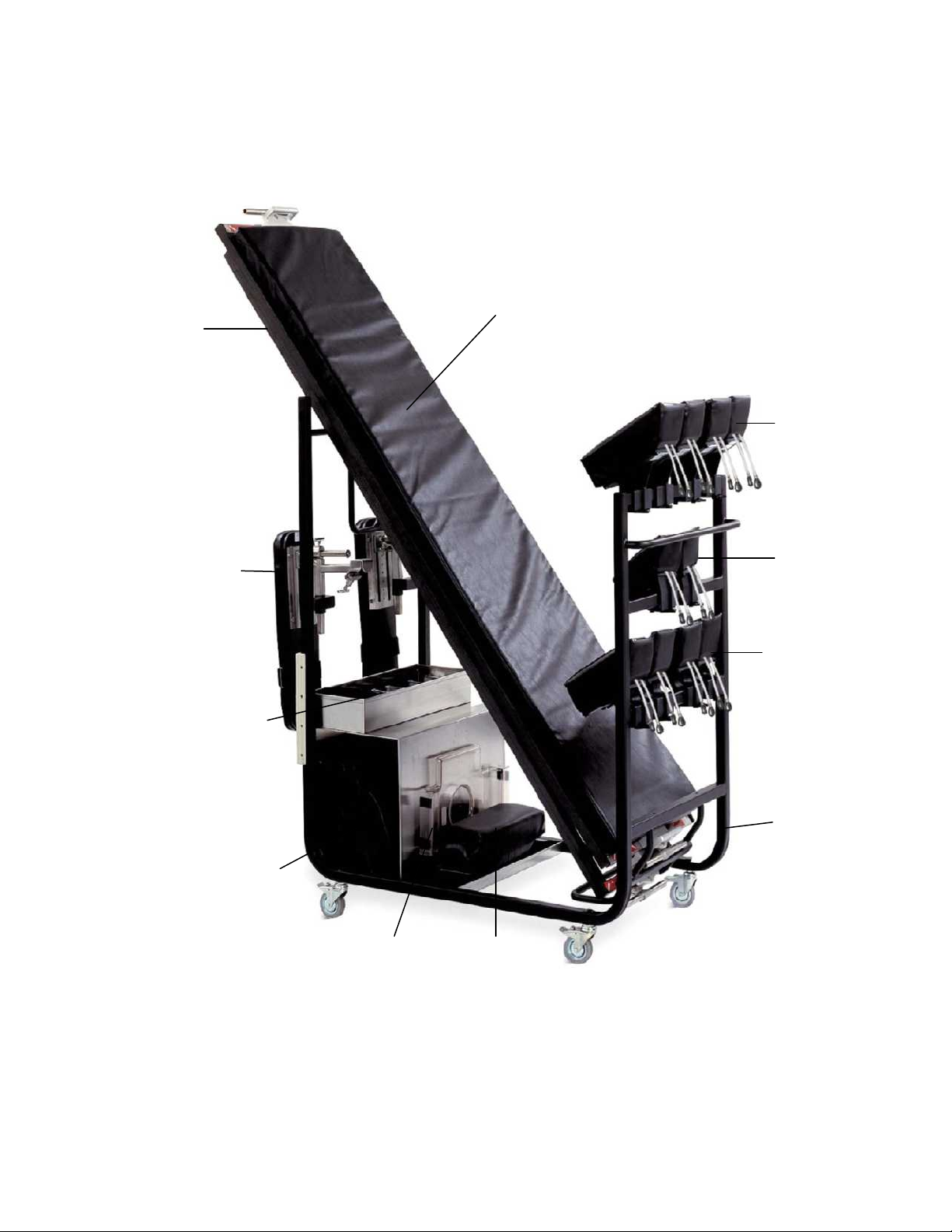
9.0 CART AND STORAGE IDENTIFICATION
The equipment cart provides a convenient storage method for all components of the
Jackson Spinal Surgery System. It is designed to allow easy access to all components
and prevent damage while stored. The equipment cart is Mizuho OSI P/N 5864.
Jackson spinal
surgery top
(below)
Radiolucent
imaging top
Hip pads
Articulating
arm boards
Thigh pads
Hip pads
Safety
straps
Leg support
sections and leg sling
Figure 54: Equipment cart with all equipment properly stored.
Head support
section
Chest
pad
Equipment
cart
MIZUHOSI 2009 NW0504 Rev. D
46
Page 47
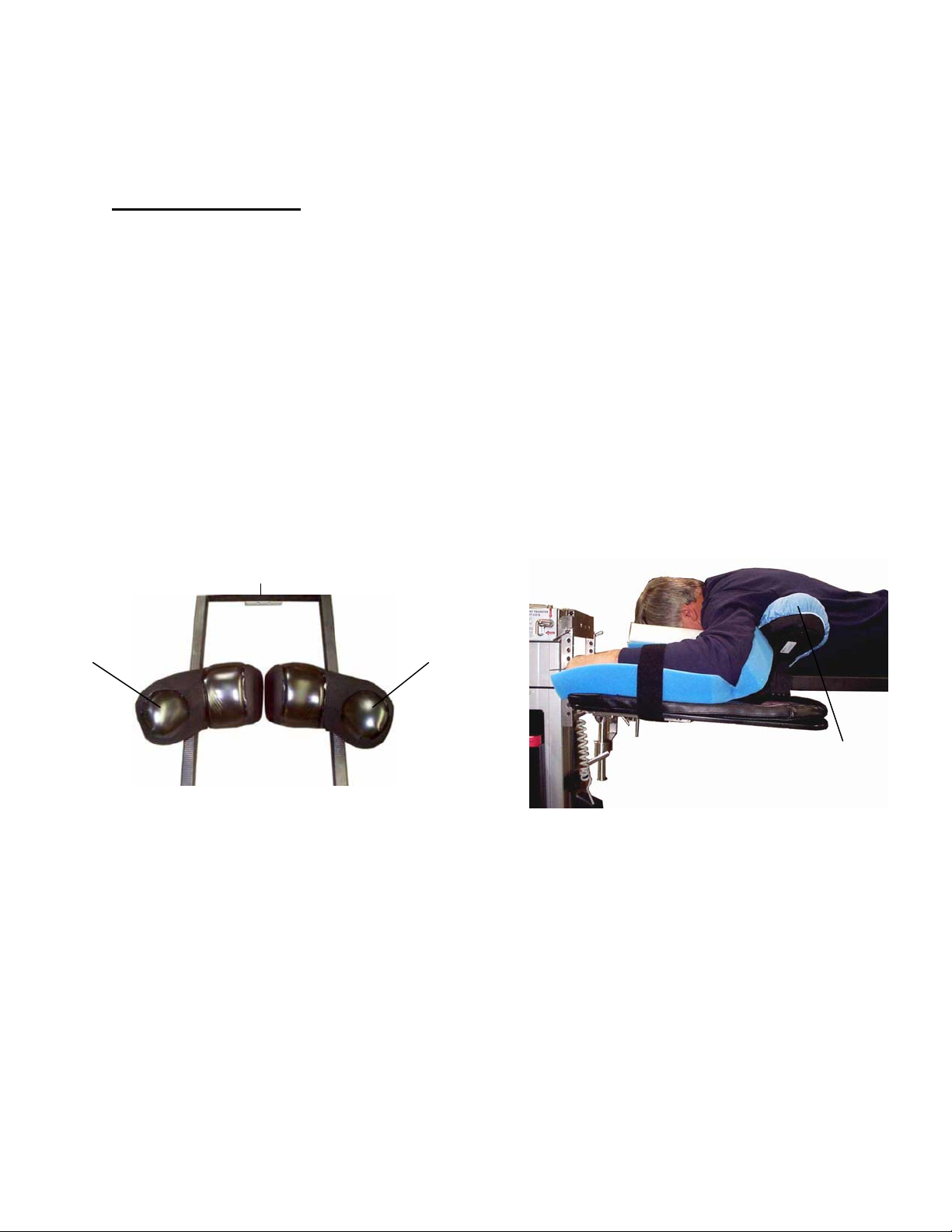
10.0 USE OF OPTIONAL ACCESSORIES
A variety of optional accessories are available for use on the Jackson Spinal Surgery or
Radiolucent Imaging Tops. See section 11.0 for part numbers when ordering these
devices.
10.1 Dual Chest Pads
The Mizuho OSI 5840-820 dual chest pads may be used in place of the standard single
piece chest pad on the Jackson Spinal Surgery Top. This pad set provides increased
lateral support and a larger surface area to contact the patient. These pads are
beneficial if it is anticipated that the spinal surgery top will laterally rotated frequently
during the surgical procedure.
NOTE: The dual chest pads are right- and left-sided pads that are labeled accordingly.
The pads must be oriented toward the patient when the patient is positioned prone on
them. Confirm the pads are applied to the appropriate side of the spinal surgery top.
The chest pads should contact the patient so the top edges of the chest pads are
parallel to the patient’s supra-sternal notch. The lateral support section on the dual
chest pads should encompass the chest wall and should be inferior to the brachial
plexus. Assess to confirm that the patient’s arms are cephalad of the pads and that the
brachial plexus is not impeded by the chest pads.
Lateral support section
on left chest pad
Figure 55: Dual chest pad set on spinal top
Head end
Lateral support
section on right
chest pad
Lateral support pad on left
chest pad
Figure 56: Patient on dual chest pads
MIZUHOSI 2009 NW0504 Rev. D
47
Page 48

10.2 Wilson Plus™ Radiolucent Wilson Frame
The Mizuho OSI 5321G Wilson Plus™ Radiolucent Wilson Frame for the Jackson
Spinal Surgery Top may be used in place of the chest, hip and thigh pads for positioning
on the spinal top (see Figure 57). The Wilson Plus™ spinal flexion frame positioner has
carbon composite construction which allows for unrestricted radiolucency and C-Arm
integration. It is also adjustable intraoperatively and provides a convenient and stable
method of maintaining a patient in the flexed position. The Wilson Plus™ RWF may be
used for laminectomy, decompression or microdiscectomy surgeries. Refer to the
Wilson Plus™ Radiolucent Wilson Frame user guide for complete instructions.
Head support section
Translating arm board
Figure 57: Wilson Plus™ on Jackson Spinal Surgery Top
Figure 58: Patient on Wilson Plus™ frame
Wilson Plus™ Frame
Leg supports section
MIZUHOSI 2009 NW0504 Rev. D
48
Page 49

11.0 5943 JACKSON SPINAL SURGERY TOP STANDARD COMPONENTS
5840-831 Jackson Spinal Surgery Top assembly (500lbs)
b
a
5927 Radiolucent Imaging Top (500lbs)
(a) 5840-726 Imaging top assembly
(b) 5840-7028 Imaging top Tem pur- Med® pad assembly
5840-389 Cervical traction vector
5840-361 “T” pin
5840-277 Head support section
MIZUHOSI 2009 NW0504 Rev. D
5840-370 H-frame support assembly
49
Page 50

JACKSON SPINAL SURGERY TOP STANDARD COMPONENTS
a
b
5840-450 Leg sling
a
Chest pad
(a) 5840-7569 Chest pad assembly
(b) 5840-580 Chest support plate
a
c
Safety straps (for Jackson Spinal Top)
(a) 5840-45 Buttock strap
(b) 5840-43 Strap, 60”
(c) 5840-44 Strap, 90” (4 included)
b a
5855-550 Safety strap (for Radiolucent Imaging Top)
(a) 5855-551 Strap assembly, female end
(b) 5855-552 Strap assembly, male end
a
b
b
5840-24 Leg support section (leg board)
c
(a) 5840-7030 Support section Tempur- Med® pad
assembly (1 inch)
(b) FE00281 Support section plate
c
d
b
b
5808 Patient care kit
(a) GentleTouch® prone positioning pillow
(b) TLC™ arm cradles, foam
(c) Shearguard® chest pillow
(d) Hip pad covers
5379 Articulating arm board
(a) 5379-35 Arm board mounting bracket
(b) 5379-60 Articulating arm board assembly
(c) 5379-7722 Tempur- Med®Arm board pad (1 inch)
MIZUHOSI 2009 NW0504 Rev. D
50
a
Page 51

5943 JACKSON SPINAL SURGERY TOP STANDARD COMPONENTS
b
b
a
5876-7 Thigh pad left, w/Shearguard gel
(a) 5840-758 Base assembly, thigh left
(b) 5876-23 Gel pad assembly
b
5876-5 Hip pad small, w/Shearguard (two shown)
(a) 5840-755 Base assembly, hip small
(b) 5876-22 Gel pad assembly, small
b
a a
5876-3 Hip pad large. w/Shearguard (two shown)
(a) 5840-756 Base assembly, hip large
(b) 5876-20 Gel pad assembly, large
a
5876-6 Thigh pad right, w/Shearguard Gel
(a) 5840-757 Base assembly, thigh right
(b) 5876-24 Gel pad assembly
b
a a
a a
5876-4 Hip pad medium, w/Shearguard (two shown)
(a) 5840-754 Base assembly, hip med
(b) 5876-21 Gel pad assembly, med
c
d
(Common to all hip and thigh pads)
(c) 5840-736 Shoulder washer
(d) AABB100DDF Nylon Hex HC screw
(e) HB5840-488 Lock lever
AABF050HSF Nylon set screw (not shown)
DETAIL
e
MIZUHOSI 2009 NW0504 Rev. D
51
Page 52

12.0 5943APJACKSON SPINAL SURGERY TOP WITH ADVANCED CONTROL PAD
SYSTEM
ACP TEMPUR-MED® Pads:
Set of 8 pads P/N 5996-200
(2) Small hip pads p/n – 5996-207
(2) Regular (medium) hip pads p/n: 5996-208
(2) Large hip pads p/n: 5996-209
5996-5 Variable Speed Controller for ACP
(1) Thigh pad (right) p/n: 5996-206,
Thigh pad (left) p/n: 5996-205
Box of 6 packages
Individual package of tubing
5996-12 ACP Quick connect tubing (12 packages /1 case)
1 Case equals 2 boxes of tubing (6 packages /box)
5996-12 ACP Quick connect tubing (12 packages /1 case)
1 Case equals 2 boxes of tubing (6 packages /box)
MIZUHOSI 2009 NW0504 Rev. D
52
Page 53

13.0 OPTIONAL ACCESSORIES
a
b
5888 Retractor adapter for JST
(for use on the spinal surgery top)
(a) 5888-1 Bracket assembly
(b) 5880-14 Lateral armboard mount
5393 Clark socket
(a) HB5393-8 Handle assembly
5855-830 Side rail adapter
(for use on the imaging top, 5927 radiolucent and 5855
orthopedic trauma top)
a
5394 Side rail clamp socket
b a
5840-820 Dual chest pad (set)
(a) 5840-801 – Left chest pad
(b) 5840-800 – Right chest pad
5839 A/P cassette tray for use on 5943 Jackson frame
or 5927 Radiolucent Imaging Top
(a) 5839-1 A/P Cassette tray assembly
(b) 5839-2 A/P Cassette clamp assembly
MIZUHOSI 2009 NW0504 Rev. D
53
Page 54

OPTIONAL ACCESSORIES
b
d
b
c
a
5356 Pivoting arm board w/ 2” pad
(a) 5356-7000 Arm board Tempur- Med® pad
(b) HB5362-6 Pivoting arm board w/ o pa d
c
d
a
b
5857 Cross arm support w/1” pad
(requires clark socket 5393)
(a) 5855-402 Knob assembly
(b) 5855-101 Arm cross upright
(c) 5857-7000 Cross arm Tempur- Med® pad assembly
(d) 5855-102 Arm cross assembly weldment
5364 Lateral arm board Set w/2” Tempur- Med® pads
(requires clark socket 5393)
(a) HB5364-3 Lower plate weldment
(b) 5364-7018 Tempur- Med® Pad
(c) HB914-516 Drop handle
(d) 5364-34 Upper arm board
(e) HB5364-6 Knob
e
5321G Wilson Plus Radiolucent Wilson frame
for Mizuho OSI Jackson Spinal Surgery Table Top
5379 Translating arm board
(a) 5840-740 Arm board mounting bracket
(b) 5376-1 Translating arm board assembly
(c) 5379-7722 Arm board Tempur- Med® pad (1 inch)
MIZUHOSI 2009 NW0504 Rev. D
54
Page 55

OPTIONAL ACCESSORIES
a a
5873 Coupler II assembly adaptor (includes adaptor
for radiolucent Mayfield)
(a) 5846 Spinal top adapter bracket (set)
5873-300 Radiolucent DORO® adaptor (not pictured)
5879-2 Anterior extension positioner, 5-inch
pad with bladder
5979-1 Cervical Management Base Unit
5979-200 Radiolucent Mayfield adaptor
5979-300 Radiolucent Doro® adaptor
Complete Cervical Management Set
5879-2 Anterior extension positioner, 5-inch
pad with bladder
5880-09 Spine operating top
5979-1 Cervical Management Base Unit
5979-200 Radiolucent Mayfield adaptor
5979-300 Radiolucent DORO® adaptor
5880-09 Spine operating top
MIZUHOSI 2009 NW0504 Rev. D
55
Page 56

14.0 CLEANING
14.1 Maintenance
Routine table care will assure many years of trouble-free service.
14.2 Cleaning and Disinfecting
Do not pour any liquid on the table top
Do not subject a modular table top to an equipment washing machine.
Refer to appropriate manual for your specific modular table base for recommended
cleaning instructions.
14.3 Table Top
Surface should be regularly wiped clean with a mild detergent solution and wiped dry
with a soft lint-free cloth.
Avoid exposing the table top to excessive moisture. Flooding, fogging or steam
cleaning is not recommended.
Blood or other fluids, etc., if allowed to remain on the table top for a long period of
time, will require special cleaning to remove. A 5% acetic acid solution or white
vinegar and water solution is especially good.
Staining and discoloration of plated or stainless steel surfaces can be corrected by
cleaning with a good commercial cleaning compound, such as Stainless Steel Magic
and then buffing surface by hand.
To disinfect exterior surface, use a quaternary ammonium or similar type disinfectant
compound according to the manufacturer’s directions for use. Wipe dry with a soft
lint-free cloth.
NOTE: Failure to thoroughly dry surface after cleaning and disinfecting may result in
the rusting of the surface.
USE OF IODOPHORS WILL CAUSE STAINING.
14.4 Casters
Casters should be cleaned and disinfected in the same manner as table top.
14.5 Table Pads
Clean table pad with mild detergent solution. Do not submerge the pads in water.
Rinse thoroughly with clean cloth; dry using lint-free cloth.
Wipe dry.
MIZUHOSI 2009 NW0504 Rev. D
56
Page 57

15.0 REPAIR AND TECHNICAL SERVICE
15.1 Contact for Parts and Service
For detailed repair information or to order replacement parts, call the Mizuho OSI
Technical Services Department:
1-800-777-4674
A Technical Services line is available from 7AM-5PM PST, Monday through Friday.
Please leave a message after business hours.
Please state slowly your name, phone number, your facility name and city, and affected
equipment model number.
An e-mail message may be left anytime at techsvcs@mizuhosi.com or through the
Technical Service icon in our web site:
www.mizuhosi.com.
15.2 Instant Support Value Package
Additional technical information and documentation is available via Mizuho OSI’s
subscription based instant support. Instant support is a web-based virtual support agent
accessible from Mizuho OSI’s web page; www.mizuhosi.com. Instant support provides
immediate and effective answers to problems and questions on a 24/7 basis.
The Instant Support Value Package (ISVP) is a comprehensive support package
designed to enhance the hospitals internal equipment support efforts. Contact your
local Mizuho OSI sales representative for subscription information and additional details
of the program.
15.3 To order Replacement Parts (RP)
1. If unable to identify part please telephone, fax or E-mail to Technical Service.
2. If part is known please telephone, fax or E-mail part number and description to
Customer Service for price and availability.
3. To place Replacement Parts (RP) order please telephone, fax or E-mail part
number, description, price, customer number and method of shipment to Customer
Service with purchase order. Indicate that order is for Replacement Parts (RP).
15.4 To return damaged parts (RGA)
1. Identify parts to be returned.
2. Telephone, fax or E-mail par t number and description of parts for return to Customer
Service for Return Goods Authorization (RGA) number.
3. Return ship parts with RGA number clearly marked on outside of package.
4. Complete Certificate of Disinfected Parts Document #40204-17.
MIZUHOSI 2009 NW0504 Rev. D
57
Page 58

15.5 To send a part for repair (RA)
1. If unable to identify part please call, fax or E-mail to Technical Service.
2. If part is known please telephone, fax or E-mail part number and description to
Technical Service for Repair Authorization (RA) number.
3. Clean (disinfect) parts prior to shipping; complete Certificate of Disinfected Parts
Document #40204-17.
4. Ship part with RA number clearly marked on outside of package.
5. Part will be evaluated and customer will be contacted with the cost of repair.
6. After customer approval of repair cost, part will be repaired and return shipped to
customer.
15.6 EC Authorized Representative
Emergo Europe
Molenstraat 15
2513 BH The Hague
The Netherlands
Tel: (31) 70 345-5870
Fax: (31) 70 346-7299
Mayfield® is a registered trademark of the Ohio Medical Corporation.
Doro® is a registered trademark of pro med INC.
MIZUHOSI 2009 NW0504 Rev. D
58
Page 59

TABLEROS PARA CIRUGÍA DE LA COLUMNA
JACKSON Y TABLERO RADIOLÚCIDO PARA
OBTENCIÓN DE IMÁGENES 5927
MANUAL DEL USUARIO
Modelo 5943 Y 5943AP
MIZUHO OSI
30031 AHERN AVENUE UNION CITY, CA 94587
Bus: 510-429-1500 Llamada gratuita en los EE.UU.: 800-777-4674 Fax: 510-4 29- 85 00
WWW.MIZUHOSI.COM ·
MIZUHOSI 2009 NW0504 Rev. D 1
NEWHIPNEWS.COM · NEWSPINENEWS.COM
Page 60

AVISOS IMPORTANTES
PRECAUCIÓN: Para garantizar el uso seguro del equipo, LEA ESTAS
INSTRUCCIONES EN SU TOTALIDAD y conserve este manual en un lugar de fácil
acceso para su consulta futura por el personal del quirófano.
Obedezca y siga todas las advertencias, precauciones e instrucciones indicadas
en el equipo o descritas en este manual.
El símbolo
de ADVERTENCIA en este manual está concebido para alertar al
usuario de la presencia de instrucciones importantes para el funcionamiento,
el mantenimiento o la seguridad.
ADVERTENCIA:
Para prevenir la estasis y la acumulación venosa, así como la aparición de
úlceras por compresión, de neuropatías, hipotensión, hipotermia o una
derivación indebida a tierra durante la electrocirugía tisular, deben seguirse los
procedimientos preoperatorios e intraoperatorios adecuados.
NOTA: En estas instrucciones se describen las técnicas sugeridas por el fabricante.
Las disposiciones finales sobre el cuidado de cada paciente respecto al uso de este
equipo corresponden al médico responsable.
Sólo personal cualificado debe utilizar este dispositivo.
PROTECCIÓN CONTRA EL RIESGO DE CHOQUE ELÉCTRICO:
Este símbolo indica que este equipo está clasificado como parte aplicada,
TIPO B, en conformidad con la norma CEI 60601-1 y es apto, en general, para las
aplicaciones que impliquen contacto con partes externas o internas del paciente,
a excepción del corazón. El circuito del paciente está conectado a una toma de
tierra protectora y este equipo debe conectarse sólo a enchufes hembra con
toma de tierra protectora.
Este símbolo indica que, cuando el cable de alimentación no está
enchufado en el quirófano o en el centro hospitalario a un enchufe con toma
de tierra protectora, se requiere un terminal de tierra externo.
Para proteger al paciente y al personal del hospital de posibles peligros,
se requiere una conexión externa mediante un conductor de tierra entre
el terminal de tierra externo y la toma de tierra protectora.
MIZUHOSI 2009 NW0504 Rev. D
2
Page 61
ADVERTENCIA:
Los equipos eléctricos médicos requieren precauciones especiales con respecto
a la compatibilidad electromagnética (CEM) y deben instalarse y utilizarse según
la información sobre compatibilidad electromagnética proporcionada en este
manual.
ADVERTENCIA:
Los equipos eléctricos médicos pueden verse afectados por equipos portátiles
o móviles de comunicación por radiofrecuencia (RF).
ADVERTENCIA:
Este equipo no debe utilizarse al lado de otro equipo ni apilarse con otros
equipos; si fuera necesario utilizarlo en una de estas dos formas, deber
verificarse que funciona normalmente en la configuración elegida.
ADVERTENCIA:
El uso de accesorios, transductores y cables distintos a los especificados por
Mizuho OSI puede producir un aumento de las emisiones o disminuir la
inmunidad del equipo.
Eliminación de componentes eléctricos
De acuerdo con la directiva sobre residuos de aparatos eléctricos y electrónicos
(RAEE), todos los componentes eléctricos, las baterías y los componentes de
fibra de carbono deben devolverse a Mizuho OSI para ser eliminados
adecuadamente. Póngase en contacto con el servicio técnico de Mizuho OSI
llamando al +1-800-777-4674 (llamada gratuita en los Estados Unidos) para
obtener más información acerca de este requisito.
MIZUHOSI 2009 NW0504 Rev. D
3
Page 62

GENERALIDADES .............................................................................................................................6
1.0
1.1 Descripción general.......................................................................................................................6
1.2 Almacenamiento............................................................................................................................6
1.3 Aceptación y transferencia............................................................................................................6
1.4 Inspección y transferencia.............................................................................................................6
2.0 IDENTIFICACIÓN DE COMPONENTES............................................................................................7
2.1 Tablero para cirugía de la columna Jackson ................................................................................7
2.2 Tablero radiolúcido para obtención de imágenes.........................................................................8
2.3 Marco en H....................................................................................................................................9
2.4 Pasador en T.................................................................................................................................9
2.5 Correas de seguridad para paciente...........................................................................................10
2.6 Apoyabrazos articulable..............................................................................................................10
2.7 Guía de tracción cervical.............................................................................................................11
2.8 Unidad de polea..........................................................................................................................11
2.9 Identificación del dispositivo de acoplamiento............................................................................12
3.0 PROCEDIMIENTOS DE ACOPLAMIENTO DE TABLEROS ..........................................................13
3.1 Bases para mesa modular 5890/5891........................................................................................13
3.2 Bloqueo de seguridad para la transferencia del paciente 5890/5891.........................................13
3.3 Control de fricción durante la rotación 5890/5891......................................................................14
3.4 Tope de rotación de 25°..............................................................................................................15
3.5 Instalación de los marcos en H...................................................................................................15
3.6 Selección de los agujeros de montaje para el tablero................................................................17
3.7 Base de control avanzado 5892/5803.........................................................................................19
3.8 Identificación del control de la mesa 5892/5803.........................................................................19
3.9 Interruptor de bloqueo de seguridad de la rotación....................................................................20
3.10 Indicador de bloqueo de la rotación de 180° ............................................................................20
3.11 Indicador del estado de accionamiento de la inclinación..........................................................21
3.12 Instalación de los marcos en H.................................................................................................21
3.13 Selección de los agujeros de montaje para el tablero..............................................................22
4.0 PROCEDIMIENTOS DE OBTENCIÓN DE IMÁGENES ..................................................................23
4.1 Bases para mesa modular 5890/5891........................................................................................23
4.2 Bases de control avanzado 5892/5803.......................................................................................23
5.0 COLOCACIÓN EN POSICIÓN SUPINA PARA PROCEDIMIENTOS Y CIRUGÍA DE LA
COLUMNA POR VÍA ANTERIOR....................................................................................................25
5.1 Bases para mesa modular 5890/5891........................................................................................25
5.2 Bases de control avanzado 5892/5803.......................................................................................25
6.0 POSICIONAMIENTO LATERAL PARA CIRUGÍA Y PROCEDIMIENTOS DE LA COLUMNA
LUMBAR Y TORÁCICA...................................................................................................................27
6.1 Bases para mesa modular 5890/5891........................................................................................27
6.2 Bases de control avanzado 5892/5803.......................................................................................27
7.0 COLOCACIÓN EN DECÚBITO PRONO PARA PROCEDIMIENTOS Y CIRUGÍA DE LA
COLUMNA POR VÍA POSTERIOR..................................................................................................30
7.1 Bases para mesa modular 5890/5891........................................................................................30
7.2 Bases de control avanzado 5892/5803.......................................................................................30
7.3 Tablero para cirugía de la columna Jackson 5943AP con sistema ACP....................................31
7.4 Operación de los soportes para paciente ...................................................................................31
7.5 Selección de los soportes de cadera..........................................................................................32
7.6 Uso del cabestrillo para piernas..................................................................................................33
7.7 Selección del método para soporte de la cabeza.......................................................................34
7.8 Transferencia del paciente..........................................................................................................36
7.9 Posicionamiento de la cabeza ....................................................................................................37
7.10 Colocación de los brazos..........................................................................................................37
7.11 Posicionamiento del tórax.........................................................................................................37
7.12 Colocación de las caderas y los muslos...................................................................................38
7.13 Colocación de las piernas.........................................................................................................39
ÍNDICE
MIZUHOSI 2009 NW0504 Rev. D
4
Page 63

PROCEDIMIENTOS DE ROTACIÓN ...............................................................................................41
8.0
8.1 Rotación lateral o inclinación lateral intraoperatoria ...................................................................41
8.2 Bases para mesa modular 5890/5891........................................................................................42
8.3 Bases de control avanzado 5892/5803.......................................................................................42
8.4 Rotación del paciente de 180°....................................................................................................42
8.5 Preparación para la rotación.......................................................................................................43
8.6 Secuencia de compresión...........................................................................................................45
8.7 Procedimiento de rotación para las bases para mesa modular 5890/5891................................47
8.8 Procedimiento de rotación para la base de control avanzado 5892/5803..................................48
8.9 Desmontaje del tablero radiolúcido para obtención de imágenes después de la rotación.........49
8.10 Rotación del paciente de decúbito prono a supino...................................................................52
9.0 CARRO E IDENTIFICACIÓN DE LOS COMPONENTES................................................................53
10.0 USO DE ACCESORIOS OPCIONALES ..........................................................................................54
10.1 Soporte doble torácico ..............................................................................................................54
10.2 Armazón de Wilson radiolúcido Wilson Plus™.........................................................................55
11.0 COMPONENTES ESTÁNDAR DEL TABLERO PARA CIRUGÍA DE LA COLUMNA JACKSON
5943 ..................................................................................................................................................56
12.0 TABLERO PARA CIRUGÍA DE LA COLUMNA JACKSON 5943AP CON SISTEMA DE
SOPORTES DE CONTROL AVANZADO........................................................................................59
13.0 ACCESORIOS OPCIONALES .........................................................................................................60
14.0 LIMPIEZA..........................................................................................................................................63
14.1 Mantenimiento...........................................................................................................................63
14.2 Limpieza y desinfección............................................................................................................63
14.3 Tablero......................................................................................................................................63
14.4 Ruedas......................................................................................................................................63
14.5 Colchonetas para mesa ............................................................................................................63
15.0 REPARACIÓN Y SERVICIO TÉCNICO...........................................................................................64
15.1 Detalles de contacto para piezas y servicio..............................................................................64
15.2 Paquete de soporte técnico instantáneo...................................................................................64
15.3 Pedido de piezas de repuesto (RP)..........................................................................................64
15.4 Devolución de piezas defectuosas (RGA) ................................................................................65
15.5 Envío de una pieza para su reparación (RA)............................................................................65
15.6 Para el representante en la UE.................................................................................................65
MIZUHOSI 2009 NW0504 Rev. D
5
Page 64

1.0 GENERALIDADES
1.1 Descripción general
El sistema de mesa para cirugía de la columna Jackson de Mizuho OSI está compuesto
por una base para mesa modular con dos tableros intercambiables de diseño
específico y una serie de accesorios. Los dos tableros son el tablero para cirugía de la
columna Jackson y el tablero radiolúcido para obtención de imágenes.
Para obtener información detallada sobre el funcionamiento y los componentes de las
bases para mesas modulares, los sistemas de tratamiento cervical y el armazón
radiolúcido Wilson Plus™, consulte el manual del usuario correspondiente. Es preciso
entender en todos sus pormenores el uso de cada uno de estos productos para poder
realizar ciertos procedimientos con el sistema de mesa para cirugía de la columna
Jackson.
Este manual requiere que el lector esté plenamente familiarizado con el manual del
usuario y la operación de la base para mesas modulares (NW0498) de Mizuho OSI.
1.2 Almacenamiento
Cuando no se utilice, almacene el tablero en un lugar limpio y seco a una temperatura
entre 0 °C y 49 °C (32 °F y 120 °F).
Se recomienda guardar la base 5803 con el cable de alimentación enchufado
en un enchufe de corriente alterna adecuado con el interruptor de alimentación
encendido para asegurar que las baterías estén totalmente cargadas y listas
para servicio.
Si se precisa recarga, cárguense durante un mínimo de 3 horas. Después de
18 horas se dispone de una carga completa.
1.3 Aceptación y transferencia
Tras recibir el tablero, sáquelo del cajón de transporte siguiendo las instrucciones
de desembalaje. Inspeccione visualmente todas las superficies para comprobar
si se han producido daños durante el transporte.
NOTA: Cualquier daño durante el transporte debe notificarse inmediatamente
a la empresa de transporte. Es responsabilidad del destinatario realizar las
reclamaciones pertinentes por los daños sufridos durante el transporte.
1.4 Inspección y transferencia
Antes de usarlo, inspeccione el dispositivo para detectar posibles daños, desgaste
excesivo o partes que no funcionan. Inspeccione con cuidado todas las áreas críticas
e inaccesibles, las juntas, los cables de alimentación y todas las partes móviles para
detectar posibles daños.
No deben utilizarse ni procesarse los productos dañados o defectuosos. Póngase en
contacto con su agente comercial Mizuho OSI más cercano para su reparación o
sustitución.
MIZUHOSI 2009 NW0504 Rev. D
6
Page 65

2.0 IDENTIFICACIÓN DE COMPONENTES
2.1 Tablero para cirugía de la columna Jackson
El tablero para cirugía de la columna Jackson mide 43 cm (17 pulgadas) de ancho
y 213 cm (84 pulgadas) de largo. Está fabricado con un material compuesto de fibra de
carbono y soporta a pacientes de hasta 226 kg (500 libras) de peso. El tablero lleva una
etiqueta indicando el peso máximo del paciente. El tablero para cirugía de la columna
incluye los siguientes elementos como componentes estándares (figura 1):
TABLEROS PARA CIRUGÍA DE LA COLUMNA JACKSON
5943 y 5943AP (componentes estándares)
Componentes 5943 5943AP
Soporte de cadera pequeño 2 2
Soporte de cadera normal (mediano) 2 2
Soporte de cadera grande 4 2
Soporte para muslo (derecho/izquierdo) 2 2
Soporte torácico 1 1
Sección para soporte de la cabeza (placa facial) 1 1
Soportes para piernas 2 2
Cabestrillo para pierna 1 1
Correa de las nalgas 1 1
Correa de seguridad de 152 cm 1 1
Correa de seguridad de 228 cm 4 4
Apoyabrazos articulable 2 2
Figura 1: Tableros para cirugía de la columna Jackson 5943/5943AP (componentes estándar)
CABECERO
Soporte para cabeza
(placa facial)
Marco en H
Figura 2: Tablero para cirugía de la columna Jackson 5943 con componentes
(El tablero se muestra acoplado a la base de control avanzado para el sistema de mesa modular 5803.)
Soporte torácico
Apoyabrazos articulables (2)
Soportes de muslo (2)
Soportes
de cadera (2)
Soportes (placas apoya piernas)
Tablero de cirugía
de la columna
PIECERO
Marco en H
MIZUHOSI 2009 NW0504 Rev. D
7
Page 66

2.2 Tablero radiolúcido para obtención de imágenes
El tablero radiolúcido para obtención de imágenes mide 54,6 cm (21,5 pulgadas)
de ancho y 213 cm (84 pulgadas) de largo. Está fabricado con un material compuesto
de fibra de carbono y soporta a pacientes de hasta 226 kg (500 libras) de peso. Cada
tablero radiolúcido para obtención de imágenes lleva una etiqueta indicando el peso
máximo del paciente. Tanto el tablero para obtención de imágenes como los rieles
®
laterales son radiolúcidos. Incluye una colchoneta Tempur-Med
de Mizuho OSI de 5
cm de grosor y dos (2) correas de seguridad montadas en los rieles laterales.
CABECERO
Marco en H
Colchoneta
Marco en H
PIECERO
Correa de seguridad (2)
Tablero radiolúcido para
obtención de imágenes
Figura 3: Identificación de componentes del tablero radiolúcido para obtención de imágenes
(El tablero de la mesa se muestra acoplado a la base de control avanzado
para el sistema de mesa modular 5803)
NOTA: Para evitar daños, este tipo de dispositivos debe siempre sujetarse a la mesa
con los adaptadores para riel lateral Mizuho OSI (p/n 5855-830). Si los retractores, las
abrazaderas de Clark, los soportes para brazos u otros accesorios se montan
directamente al riel lateral del tablero radiolúcido para obtención de imágenes,
el tablero de fibra de carbono podría agrietarse o astillarse. En el apartado 3.0 de este
manual del usuario encontrará más información relacionada con el uso del tablero
radiolúcido para obtención de imágenes.
MIZUHOSI 2009 NW0504 Rev. D
8
Page 67

2.3 Marco en H
Los tableros para cirugía de columna Jackson y los tableros radiolúcidos para
obtención de imágenes se suministran con dos (2) marcos en H (figura 4). Los marcos
en H se utilizan para conectar los tableros a la base mediante pasadores en T.
Se necesitan cuatro (4) marcos en H para sujetar ambos tableros y realizar una
rotación de 180° del paciente (consulte el apartado 8.0, “Procedimientos de rotación”).
Figura 4: Marco en H
2.4 Pasador en T
Los tableros para cirugía de la columna Jackson y los tableros radiolúcidos para
obtención de imágenes se suministran con cuatro (4) pasadores en T (figura 5).
Los pasadores en T se utilizan para conectar los marcos en H a las barras
transversales en la base de la mesa y para conectar los tableros a los marcos en H.
Se necesitan ocho (8) pasadores en T para sujetar ambos tableros y realizar una
rotación de 180° del paciente (consulte el apartado 8.0, “Procedimientos de rotación”).
Lengüeta de bloqueo
Figura 5: Pasador en T
MIZUHOSI 2009 NW0504 Rev. D
9
Page 68

2.5 Correas de seguridad para paciente
El tablero para cirugía de la columna Jackson se suministra con seis (6) correas
de seguridad para paciente; cuatro (4) correas de 228 cm, una (1) correa de 152 cm,
y una (1) correa de nalgas (figura 6). Cuando se coloque a un paciente en el tablero
para cirugía de la columna Jackson o en el tablero radiolúcido para obtención
de imágenes, verifique que se le pongan las correas de seguridad adecuadas
y se aseguren tal como se describe en el apartado 7.0 de este manual del usuario.
Correa de las nalgas
152 cm
228 cm
Figura 6: Correas de seguridad para el paciente del tablero para cirugía de la columna Jackson
2.6 Apoyabrazos articulable
El tablero para cirugía de la columna Jackson se suministra con dos (2) apoyabrazos
articulables y abrazaderas de montaje (figura 7). Estos soportes para brazo pueden
montarse directamente en el tablero de la columna en cualquier lugar a lo largo
de la longitud del bastidor. El apoyabrazos articulable puede ajustarse en seis
direcciones según se muestra en la figura 7.
Apoyabrazos
Abrazadera
de montaje
Figura 7: Apoyabrazos articulable para el tablero para cirugía de la columna Jackson
MIZUHOSI 2009 NW0504 Rev. D
10
Page 69

2.7 Guía de tracción cervical
La base de la mesa modular está equipada con una guía de tracción cervical (figura 8).
La guía de tracción cervical permite ajustar el ángulo de fuerza (tiro) para la tracción
cervical tal como se muestra en la figura 9.
Figura 8: Guía de tracción cervical
2.8 Unidad de polea
La unidad de polea está instalada de forma permanente en la columna del cabecero
y sirve para guiar la cuerda de tracción. La guía de t racción cervical se sujeta al lado
medial del marco en H del cabecero en los agujeros de montaje para lograr el ángulo
de tracción deseado (figura 9). Se pueden añadir pesas (bolsas de arena) para lograr
la carga de tracción adecuada durante las intervenciones quirúrgicas cervicales por vía
anterior o posterior, o en cualquier otro momento que se desee tracción cervical.
El peso de tracción está conectado a una cuerda que pasa sobre la polea, atraviesa
el eje giratorio de la barra transversal del cabecero y se conecta con el aparato
de tracción del paciente (figura 10).
Figura 9: Guía de tracción cervical instalada
en el marco en H
Guía de
tracción
cervical
Cable de tracción que
conecta con el aparato de
tracción del paciente
Polea
Figura 10: Unidad de polea de tracción
Eje
giratorio
Pesa
NOTA: La cantidad de carga de tracción aplicada al paciente se deja enteramente
a la discreción del médico responsable.
MIZUHOSI 2009 NW0504 Rev. D
11
Page 70
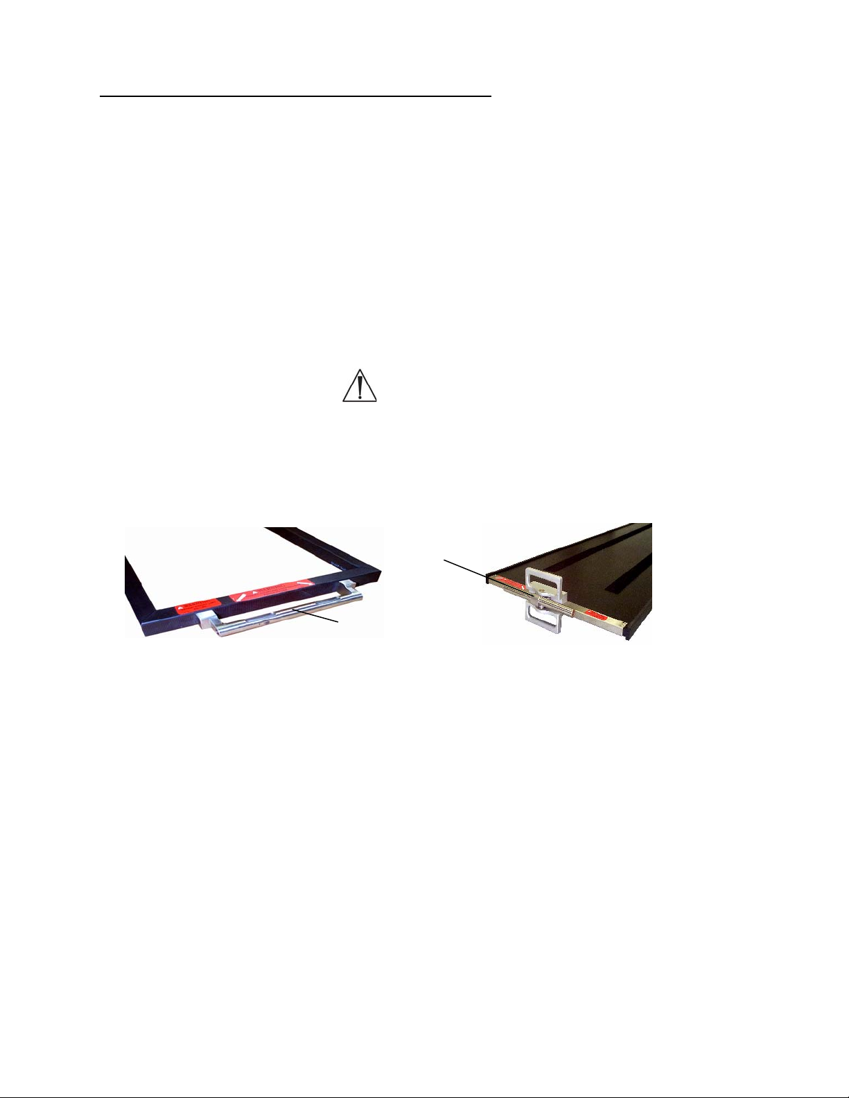
2.9 Identificación del dispositivo de acoplamiento
Identifique el dispositivo de acoplamiento en el extremo del tablero (figuras 11 y 12).
Las versiones anteriores del tablero para cirugía de la columna Jackson y de los
tableros para obtención de imágenes tienen tubos de montaje fijos. Los tableros para
cirugía de la columna Jackson fabricados con posterioridad a octubre de 1999 y los
tableros radiolúcidos para obtención de imágenes construidos con posterioridad
a enero de 1997 tienen montajes cardánicos (figura 12). Los cardanes permiten
la rotación del tablero cuando está posicionado en los límites del recorrido de
inclinación lateral y trendelenburg o trendelenburg inverso. Ambos diseños se
enganchan al marco en H de la misma manera. Las bases para mesa modular
5890/5891 pueden utilizar cualquiera de los dos tipos de dispositivos de acoplamiento;
las bases de control avanzado 5892/5803 sólo pueden utilizar montajes cardánicos
(figura 12).
ADVERTENCIA:
Los tableros pueden dañarse si se utilizan en las bases de control avanzado
5892/5803 sin montajes cardánicos (figura 12).
Tubo de montaje cardánico
Tubo de montaje fijo
Figura 11: Tubo de montaje
fijo en tablero para cirugía
de la columna Jackson
MIZUHOSI 2009 NW0504 Rev. D
12
Figura 12: Montaje cardánico
en tablero radiolúcido para
obtención de imágenes
Page 71

(
)
3.0 PROCEDIMIENTOS DE ACOPLAMIENTO DE TABLEROS
El tablero para cirugía de la columna Jackson y el tablero radiolúcido para obtención
de imágenes pueden acoplarse a cualquier base para mesa modular e intercambiarse
según se necesite para aportar flexibilidad y poder realizar el procedimiento.
NOTA: Para instrucciones completas sobre la operación y las funciones de la base
para mesa modular, consulte el manual del usuario adecuado (suministrado con
la base para mesa modular). Antes de continuar, es preciso entender en todos sus
pormenores el funcionamiento de las bases para mesa modular 5890 y 5891.
3.1 Bases para mesa modular 5890/5891
Las instrucciones siguientes atañen al uso de un tablero en la base para mesa modular
5890 o 5891. Estas bases no cuentan con la función de inclinación lateral motorizada.
3.2 Bloqueo de seguridad para la transferencia del paciente 5890/5891
Cada base modular 5890/5891 está equipada con un bloqueo de seguridad para
la transferencia del paciente en la columna del cabecero y en la del piecero. El bloqueo
de seguridad para la transferencia del paciente se acciona mediante la palanca que
sobresale del lado derecho de la caja de control en la columna del cabecero (figura 13).
Un segundo bloqueo de seguridad para la transferencia del paciente se encuentra en
el lado de la caja de control del piecero (figura 14). Cuando están accionados,
los bloqueos de seguridad para la transferencia del paciente bloquean la barra
transversal en la posición horizontal impidiendo de esta manera su rotación.
Control de fricción
durante la rotación
Barra transversal
Barra transversal
Figura 13: Columna del cabecero
se ilustran las bases 5890/5891
Bloqueo de seguridad para
la transferencia del paciente
Movimiento
de desenganche
Bloqueo de seguridad
para la transferencia
del paciente
Movimiento
de desenganche
Figura 14: Columna del piecero
(se ilustran las bases 5890/5891)
MIZUHOSI 2009 NW0504 Rev. D
13
Page 72

3.3 Control de fricción durante la rotación 5890/5891
El control de fricción durante la rotación está situado en las columnas del cabecero
y en la del piecero. En el cabecero, el control de fricción durante la rotación es la
palanca en ángulo recto grande en la parte superior de la caja de control (figura 13).
En el piecero, el control de fricción durante la rotación es la palanca negra que está
situada en la parte inferior de la caja de control (figura 15). El control de fricción durante
la rotación puede apretarse para que actúe como freno de fricción o puede ajustarse
para sujetar el tablero en cualquier grado de inclinación lateral. Como freno de fricción,
puede aflojarse para mantener la resistencia deseada y aun así ajustar el tablero
a un grado de inclinación diferente. Cuando se afloja al máximo, el control de fricción
durante la rotación permite rotaciones de 180°. Gire el control de fricción durante
la rotación en sentido horario para aumentar la fricción y en sentido antihorario para
reducirla. Siempre que se quiera inmovilizar el tablero en una posición, se recomienda
ajustar el control de fricción durante la rotación a la posición de máxima fricción
(giro a tope en sentido horario).
Barra transversal
Figura 15: Columna del piecero (se ilustran las bases 5890/5891)
Control de fricción
durante la rotación
NOTA: Como la palanca de control de fricción durante la rotación del piecero tiene una
amplitud de movimiento limitada, es posible que en alguna ocasión no sea posible
aflojar o apretar totalmente el freno con un solo giro de la palanca. En este caso, una
vez que se alcance la máxima amplitud del movimiento, baje la palanca. Esto
desactivará el mecanismo y la palanca podrá llevarse a su posición de inicio sin que
el grado de fricción se vea afectado. Repita el proceso hasta que se consiga el grado
fricción deseado.
MIZUHOSI 2009 NW0504 Rev. D
14
Page 73

3.4 Tope de rotación de 25°
Cada base modular base está equipada con un tope de rotación de 25°. El tope de
rotación se acciona mediante la palanca situada en el lado izquierdo de la caja de
control cerca de la parte superior de la columna del cabecero. Puede activarse
fácilmente con la mano izquierda cuando se está de pie en la cabecera de la mesa
(figura 16). Cuando está accionado, el tope de rotación impide una rotación lateral
superior a los 25° con respecto a la posición horizontal. El tope de rotación debería
estar activado normalmente, y desactivarse únicamente durante una rotación de 180°.
Figura 16: Tope de rotación de 25° en la columna del cabecero (se ilustran las base s 58 90/5891)
Barra transversal
Movimiento de desenganche
Tope de rotación de 25°
3.5 Instalación de los marcos en H
El siguiente procedimiento de acoplamiento presupone que las columnas del cabecero
y del piecero no tienen colocado ni un tablero para cirugía de la columna Jackson
ni un tablero radiolúcido para obtención de imágenes.
1. Bloquee la base de la mesa en posición activando los frenos de las cuatro
(4) ruedas.
2. Instale un marco en H en la barra transversal del cabecero y sujételo con un
pasador en T (figuras 17 y 18).
Lengüeta de bloqueo
Barra transversal
CABECERO
Barra transversal
Pasador en T
Figura 17: Marco en H alineado con perno de montaje
y pasador en T preparado para su inserción
MIZUHOSI 2009 NW0504 Rev. D
Marco en H
Perno de montaje
15
Pasador en T
Figura 18: Inserción del pasador en T en el marco
en H y en la barra transversal de la columna
del cabecero (se ilustran las bases 5890/5891)
Marco en H
Page 74

ADVERTENCIA:
Si no se coloca el pasador en T, la mesa colapsará y el paciente se caerá.
3. Instale un marco en H en la barra transversal del piecero y fíjelo con un pasador
en T. Retraiga totalmente la barra transversal del piecero deslizándola hacia
la columna del piecero (figura 19).
Lengüeta de bloqueo
Figura 19: Marco en H instalado – columna del piecero (se ilustran las bases 5890/5891)
Barra transversal
Pasador en T
COLOCADO
Marco en H
Control de fricción durante la rotaci ón
Pasador en T
DESLIZAR
4. Accione el bloqueo de seguridad para la transferencia del paciente en las columnas
del cabecero y del piecero (figuras 13 y 14).
ADVERTENCIA:
Para transferir al paciente de manera segura, es necesario accionar el bloqueo
de seguridad de la transferencia antes de transferirle para impedir que el tablero
gire. La omisión de lo anterior puede resultar en la caída del paciente.
5. Gire la palanca de control de fricción durante la rotación en las columnas del
cabecero y del piecero a tope en sentido horario para llevarla a la posición de
máxima fricción (figuras 13 y 15).
6. Active el tope de rotación de 25° en la columna del cabecero (figura 16).
ADVERTENCIA:
Antes de acoplar los tableros, verifique que los dos (2) marcos en H estén bien
montados en la barra transversal. Confirme que cada uno de los pasadores
en T atraviesa de lado a lado el marco en H y la barra transversal
correspondiente, y que la lengüeta de bloqueo está visible y se mueve
libremente. La omisión de lo anterior puede resultar en la caída del paciente.
MIZUHOSI 2009 NW0504 Rev. D
16
Page 75

3.6 Selección de los agujeros de montaje para el tablero
Al seleccionar el agujero de montaje del marco en H, lo que se pretende es que
el centro de gravedad del paciente quede a la altura o por debajo de la línea media
de las barras transversales. Para la mayoría de los pacientes, el cuarto agujero
de montaje debajo de la barra transversal es la posición adecuada (figura 20).
Línea media de las barras transversales
Centro de gravedad del paciente
Figura 20: Centro del eje de gravedad del paciente debajo de la línea media de las barras transversales
NOTA: Para realizar la siguiente secuencia de acciones se precisan dos personas.
7. Seleccione los agujeros de montaje adecuados en el marco en H para sostener
el tablero. Inserte primero el pasador en T en el marco en H en la columna del
cabecero. Alinee el tubo de montaje en el tablero con el agujero de montaje
seleccionado en el marco en H. Inserte el pasador en T de manera que entre en el
marco en H, atraviese el tubo de montaje y salga por el lado opuesto del marco
en H. La lengüeta de bloqueo del pasador en T debe estar visible y moverse
libremente (figura 21).
Lengüeta de bloqueo
Figura 21: Columna del cabecero con tablero para cirugía de la columna Jackson acoplado
CABECERO
Marco en H
Pasador en T
Tablero para cirugía
de la columna Jackson
ADVERTENCIA:
Compruebe que el pasador en T entra en el marco en H, atraviesa el tubo
de montaje de la mesa y sale por el lado opuesto del marco en H, y que la
lengüeta de bloqueo del pasador en T está visible y se mueve libremente.
MIZUHOSI 2009 NW0504 Rev. D
17
Page 76

8. Para acoplar el piecero del tablero, deslice el marco en H y la barra transversal
según sea necesario para acomodar la longitud del tablero (figura 22). Alinee el tubo
de montaje en el tablero con el agujero seleccionado en el marco en H del piecero.
Inserte el pasador en T de manera que entre en el marco en H, atraviese el tubo
de montaje en el tablero y salga por el lado opuesto del marco en H. Esto debe
hacerse al mismo nivel que el agujero de montaje en el que se montó el cabecero.
La lengüeta de bloqueo del pasador en T debe estar visible y moverse libremente.
Tablero para cirugía
de la columna Jackson
Figura 22: Columna del piecero con tablero de la columna Jackson acoplado
Marco en H
Pasador en T
PIECERO
Lengüeta de bloqueo
ADVERTENCIA:
La omisión de los procedimientos anteriormente indicados para fijar el marco
en H a las barras transversales y el tablero a los marcos en H puede dar lugar
a la caída del paciente.
Figura 23: Tablero para cirugía de la columna Jackson montado en la base para mesa
modular 5890/5891 (se ilustra sin los soportes para el paciente)
MIZUHOSI 2009 NW0504 Rev. D
18
Page 77
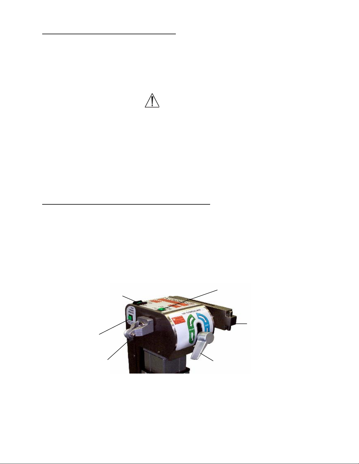
3.7 Base de control avanzado 5892/5803
El tablero para cirugía de la columna Jackson y el tablero radiolúcido para obtención de
imágenes pueden acoplarse a la base de control avanzado 5892/5803 e intercambiarse
según se necesite para aportar flexibilidad y poder realizar el procedimiento. Identifique
el dispositivo de acoplamiento en el extremo del tablero tal como se describe en el
apartado 2.9, figuras 11 y 12 de este manual.
ADVERTENCIA:
El tablero para cirugía de la columna Jackson y el tablero radiolúcido para
obtención de imágenes utilizados en la base de control avanzado 5892/5803
deben tener cardanes (figura 12). Las versiones anteriores de estos tableros no
tienen cardanes. El tablero puede dañarse si se utiliza sin un montaje cardánico.
NOTA: Para obtener instrucciones detalladas sobre la operación y las funciones de la
base de control avanzado 5892/5803, consulte el manual del usuario adecuado
(suministrado con la base de control avanzado). Antes de continuar, es preciso
entender en todos sus pormenores el funcionamiento de la base de control avanzado
5892/5803.
3.8 Identificación del control de la mesa 5892/5803
El cabecero de la base de control avanzado 5892/5803 está equipado con tres luces
indicadoras. Estas son: 1) luz indicadora de bloqueo de la rotación de 180°, 2) luz de
estado de accionamiento de la inclinación y 3) luz indicadora de bloqueo de seguridad
de la rotación. Compruebe que el interruptor de bloqueo de seguridad de la rotación
esté encendido y que la palanca de bloqueo de la rotación de 180° esté en la posición
bloqueada. Antes de transferir a un paciente a la mesa, las tres luces deben estar
iluminadas.
Luz indicadora / interruptor de bloqueo
de seguridad de la rotación
Luz indicadora de bloqueo de la
rotación de 180º
Luz indicadora
de accionamiento
de la inclinación
Barra transversal
Polea de tracción
Palanca de bloqueo
de la rotación de 180°
Figura 24: Luces indicadoras en la columna del cabecero de la base de control avanzado 5892/5803
MIZUHOSI 2009 NW0504 Rev. D
19
Page 78

3.9 Interruptor de bloqueo de seguridad de la rotación
El interruptor de bloqueo de seguridad de la rotación (con el indicador iluminado)
bloquea la función de inclinación lateral. Esta característica está diseñada para prevenir
la inclinación lateral involuntaria del tablero. El interruptor de bloqueo de seguridad de
la rotación sólo debe apagarse cuando se vaya a realizar una rotación de 180°. Si la luz
indicadora del interruptor de bloqueo de seguridad de la rotación no está iluminada,
pulse el interruptor a la posición de encendido.
3.10 Indicador de bloqueo de la rotación de 180°
Cuando la luz del indicador de bloqueo de la rotación de 180° está encendida, significa
que este bloqueo está accionado y que la mesa no puede girarse 180°. Si la luz del
indicador de bloqueo de la rotación de 180º no está encendida, gire la palanca de
bloqueo de la rotación en sentido horario hasta que se encienda.
NOTA: Si se va realizar una rotación de 180° con el paciente en la mesa, la palanca de
bloqueo de la rotación debe girarse en sentido antihorario aproximadamente medio giro
pasado el punto en que la luz del indicador de bloqueo de la rotación se apague.
Al girar la palanca de bloqueo hasta ese punto, se reduce la resistencia del control
de fricción, y eso permite que el tablero gire más libremente durante la rotación.
Si se desea aún menos fricción, se puede girar en sentido antihorario aún más
la palanca de bloqueo, según sea necesario.
Después de finalizar la rotación del paciente, gire la palanca de bloqueo de la rotación
en sentido horario hasta que se encienda la luz del indicador de bloqueo de la rotación.
ADVERTENCIA:
Si la luz del indicador de bloqueo de la rotación no está encendida, el tablero está
DESBLOQUEADO; esto es así independientemente de que la palanca de bloqueo
se haya girado en sentido horario o antihorario. Después de una rotación de 180º,
gire siempre la palanca de bloqueo hasta que la luz del indicador de bloqueo
de la rotación se encienda. Si se necesita un mayor freno de fricción
en la rotación, gire la palanca en sentido horario hasta que se consiga la fricción
deseada.
ADVERTENCIA:
Antes de transferir a un paciente a la mesa, las tres luces deben estar iluminadas.
No transfiera al paciente a la mesa hasta que las tres luces estén encendidas.
MIZUHOSI 2009 NW0504 Rev. D
20
Page 79
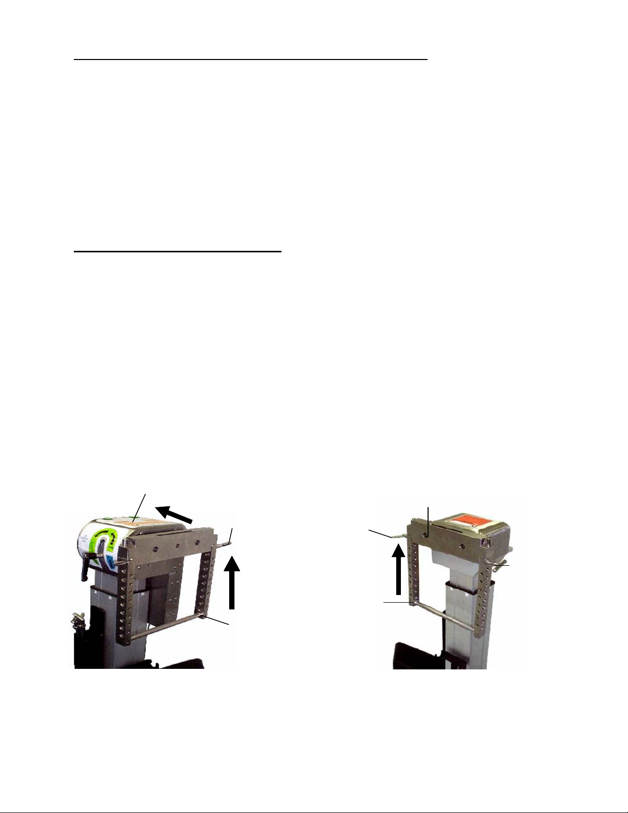
3.11 Indicador del estado de accionamiento de la inclinación
La luz del estado del accionamiento de la inclinación se enciende cuando el mecanismo
de inclinación lateral motorizado está en el punto medio del recorrido de inclinación
lateral motorizada de +/- 25°. Si el indicador de accionamiento de la inclinación no está
iluminado, accione la función de inclinación lateral en la dirección apropiada con el
mando de mano hasta que se ilumine el indicador. Cuando el indicador del estado del
accionamiento de la inclinación está iluminado, la barra transversal del cabecero debe
estar horizontal. Si la barra transversal del cabecero no está horizontal, el mecanismo
interno de accionamiento de la inclinación no está sincronizado con la barra
transversal. Consulte el apartado sobre sincronización de la función de inclinación
lateral en la guía del usuario de la base de control avanzado 5892 o en el manual
de usuario de la base 5803 para ver cómo restablecer esta función.
3.12 Instalación de los marcos en H
El procedimiento de acoplamiento que se describe a continuación presupone que en la
columna del cabecero y en la del piecero aún no se ha colocado el tablero para cirugía
de la columna Jackson ni el tablero radiolúcido para obtención de imágenes.
El procedimiento de acoplamiento del tablero para cirugía de la columna Jackson o del
tablero radiolúcido para obtención de imágenes es como sigue:
1. Bloquee la mesa en su lugar activando los cuatro (4) frenos de las ruedas.
2. Instale el marco en H en la barra transversal del cabecero y fíjelo con un pasador
en T (figura 25). Retraiga completamente la barra transversal del cabecero contra
la columna del cabecero.
3. Instale el marco en H en la barra transversal del piecero y fíjelo con un pasador
en T (figura 26).
Unidad corredera con articulación
CABECERO
Pasador en T
Lengüeta
de bloqueo
Barra transversal
PIECERO
Figura 25: Marco en H instalado – columna
del cabecero de la base de control
MIZUHOSI 2009 NW0504 Rev. D
avanzado 5892/5803
COLOCADO
Marco en H
COLOCADO
Marco en H
Figura 26: Marco en H instalado – columna
21
del piecero de la base de control
avanzado 5892/5803
Pasador en T
Page 80

3.13 Selección de los agujeros de montaje para el tablero
Al seleccionar el agujero de montaje del marco en H, lo que se pretende es que el
centro de gravedad del paciente quede a la altura o por debajo de la línea media de las
barras transversales. Para la mayoría de los pacientes, el cuarto agujero de montaje
debajo de la barra transversal es la posición adecuada (figura 20).
NOTA: Para realizar la siguiente secuencia se precisan dos personas.
4. Seleccione los agujeros de montaje adecuados en el marco en H para sostener
el tablero. Inserte primero el pasador en T en el marco en H en la columna del
piecero. Alinee el tubo de montaje en el tablero con el agujero de montaje
seleccionado en el marco en H. Inserte el pasador en T de manera que entre en el
marco en H, atraviese el tubo de montaje y salga por el lado opuesto del marco
en H. La lengüeta de bloqueo del pasador en T debe estar visible y moverse
libremente (figura 22).
ADVERTENCIA:
Compruebe que el pasador en T entra en el marco en H, atraviesa el tubo de
montaje de la mesa y sale por el lado opuesto del marco en H y que la lengüeta
de bloqueo del pasador en T está visible y se mueve libremente. La omisión de
lo anterior puede resultar en el colapso de la mesa y en la caída del paciente.
5. Para acoplar el cabecero del tablero, deslic e el marco en H y la barra transversal en
dirección opuesta al piecero (se ilustra en la figura 25) todo lo que sea necesario
para poder insertar el tablero en toda su longitud. Seleccione los agujeros de
montaje adecuados en el marco en H para sostener el tablero. Alinee el tubo de
montaje en el tablero con el agujero de montaje seleccionado en el marco en H.
Inserte el pasador en T de manera que entre en el marco en H, atraviese el tubo de
montaje y salga por el lado opuesto del marco en H. Esto debe hacerse al mismo
nivel que el agujero de montaje en el que se montó el cabecero. La lengüeta de
bloqueo del pasador en T debe estar visible y moverse libremente (figura 21).
En la figura 23 puede verse un tablero completamente acoplado a la base de la mesa.
ADVERTENCIA:
La omisión de los procedimientos anteriormente indicados para fijar el marco en
H a las barras transversales y el tablero a los marcos en H puede dar lugar a la
caída del paciente.
MIZUHOSI 2009 NW0504 Rev. D
22
Page 81

4.0 PROCEDIMIENTOS DE OBTENCIÓN DE IMÁGENES
Para la mayoría de los procedimientos de obtención de imágenes, acople el tablero
radiolúcido para obtención de imágenes de la forma siguiente:
1. Bloquee la base de la mesa en posición activando los frenos de las cuatro (4)
ruedas.
2. Verifique que los controles de la mesa estén bloqueados.
4.1 Bases para mesa modular 5890/5891
1. Accione los bloqueos de seguridad para la transferencia del paciente en la columna
del cabecero y en la del piecero (consulte el apartado 3.0, figuras 13 y 14).
2. Coloque la palanca de control de fricción durante la rotación en la posición
de máxima fricción en la columna del cabecero y en la del piecero (consulte
el apartado 3.0, figuras 13 y 15).
3. Accione el tope de la rotación de 25° (consulte el apartado 3.0, figura 16).
4.2 Bases de control avanzado 5892/5803
1. Confirme que el indicador del interruptor de bloqueo de seguridad de la rotación
esté iluminado (consulte el apartado 3.0, figura 24).
2. Confirme que el indicador de bloqueo de la rotación esté iluminado (consulte el
apartado 3.0, figura 24).
3. Confirme que el indicador del estado de accionamiento de la inclinación esté
iluminado (consulte el apartado 3.0, figura 24).
4.2.1 Acople el tablero radiolúcido para obtención de imágenes con colchoneta
(consulte el apartado 3.0, “Procedimientos de acoplamiento de tableros”), según
la base utilizada.
4.2.2 Transfiera al paciente en posición supina al tablero radiolúcido para obtención
de imágenes. Coloque la correa de seguridad para el paciente y asegúrela.
Figura 27: Paciente en posición supina sobre el tablero radiolúcido para obtenci ón de imágenes
con apoyabrazos pivotantes
MIZUHOSI 2009 NW0504 Rev. D
23
Page 82

Los rieles laterales radiolúcidos están diseñados para sujetar los soportes para brazo
quirúrgicos. Recomendamos utilizar los apoyabrazos pivotantes de Mizuho OSI (p/n
5356), tal como se muestra en la figura 28. Estos soportes deben utilizarse junto con
los adaptadores para riel lateral Mizuho OSI (p/n 5855-830) para no dañar los rieles
laterales del tablero.
Apoyabrazos
pivotante
Colchoneta del tablero
para obtención de imágenes
Adaptador para riel
lateral (p/n 5855-830)
Riel lateral radiolúcido del tablero
para obtención de imágenes
Figura 28: Apoyabrazos pivotante con adaptador para riel lateral en el tablero radiolúcido
para obtención de imágenes
MIZUHOSI 2009 NW0504 Rev. D
24
Page 83

5.0 COLOCACIÓN EN POSICIÓN SUPINA PARA PROCEDIMIENTOS Y CIRUGÍA
DE LA COLUMNA POR VÍA ANTERIOR
Para procedimientos de la columna por vía anterior puede utilizarse el tablero
radiolúcido para obtención de imágenes siguiendo estos pasos:
1. Bloquee la base de la mesa en posición activando los frenos de las cuatro (4)
ruedas.
2. Verifique que los controles de la mesa estén bloqueados.
5.1 Bases para mesa modular 5890/5891
1. Accione los bloqueos de seguridad para la transferencia del paciente en la columna
del cabecero y en la del piecero (consulte el apartado 3.0, figuras 13 y 14).
2. Lleve los controles de fricción durante la rotación a la posición de máxima fricción
en la columna del cabecero y en la del piecero (consulte el apartado 3.0,
figuras 13 y 15).
3. Accione el tope de la rotación de 25° (consulte el apartado 3.0, figura 16).
5.2 Bases de control avanzado 5892/5803
1. Confirme que el indicador del interruptor de bloqueo de seguridad de la rotación
esté iluminado (consulte el apartado 3.0, figura 24).
2. Confirme que el indicador de bloqueo de la rotación esté iluminado (consulte el
apartado 3.0, figura 24).
3. Confirme que el indicador del estado de accionamiento de la inclinación esté
iluminado (consulte el apartado 3.0, figura 24).
5.2.1 Acople el t ablero radiolúcido para obtención de imágenes con colchoneta
o el posicionador de extensión anterior 5879-2 con cámara de aire de
12,5 cm (consulte el apartado 3.0, “Procedimientos de acoplamiento de
tableros”), según la base utilizada.
NOTA: Para cirugía cervical anterior en la que se requiera extensión de columna
cervical, se recomienda utilizar el posicionador de extensión anterior Mizuho OSI (p/n
5879-2) con cámara de aire de 12,5 cm en lugar de la colchoneta del tablero para
obtención de imágenes (figura 29).
5.2.2 Transfiera al paciente en posición supina al tablero radiolúcido para
obtención de imágenes. Coloque la correa de seguridad para el paciente
y asegúrela.
MIZUHOSI 2009 NW0504 Rev. D
25
Page 84
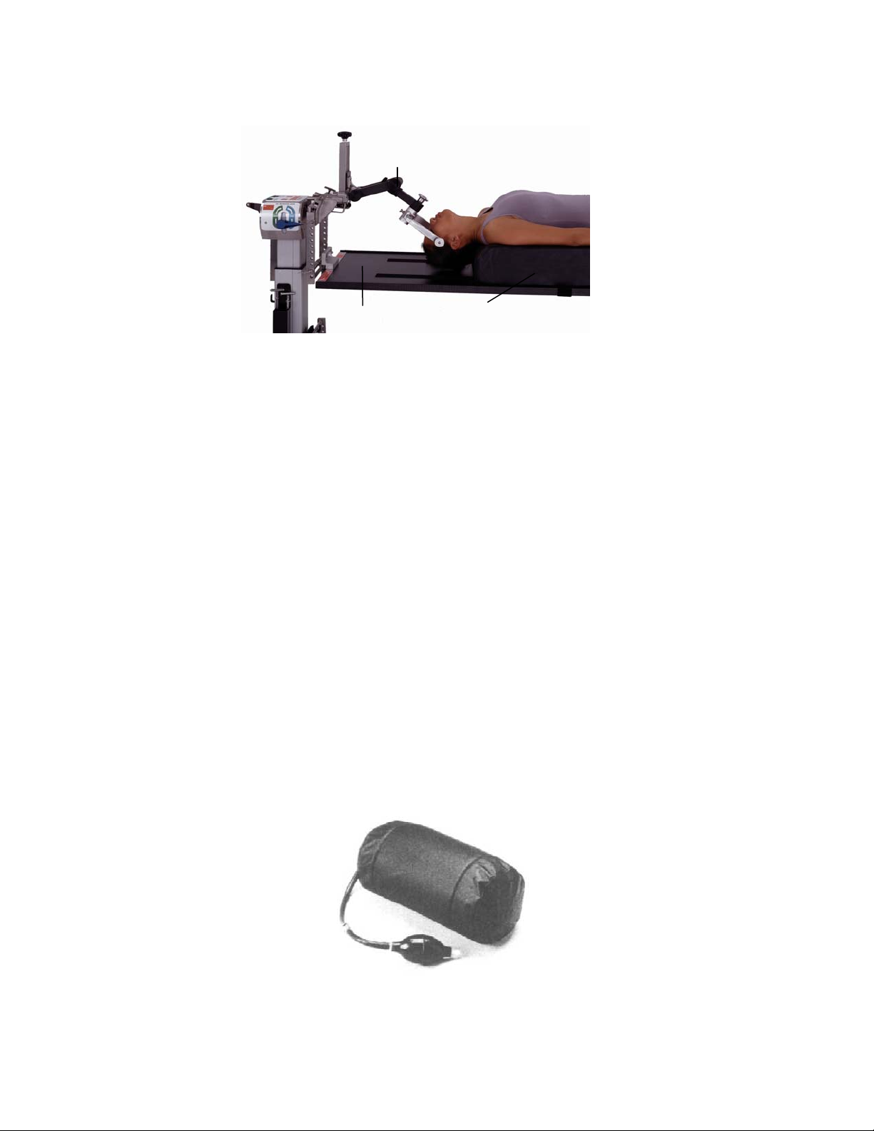
5.2.3 Los brazos pueden colocarse paralelos al paciente, junto al cuerpo,
sujetos y apoyados con almohadas y una sábana tirante.
Sistema de tratamiento cervical
Figura 29: Tablero para paciente con posicionador de extensión anterio r y sistema
Tablero para
obtención
de imágenes
de tratamiento cervical opcionales
Posicionador de extensión
anterior
5.2.4 Prepare y cubra con sábanas al paciente en la forma habitual. Esta
posición proporciona un acceso ideal a la columna cervical anterior,
y proporciona también un acceso ideal a la columna lumbar anterior
a través de un abordaje abdominal que deje al descubierto la región
lumbosacra. Si el cirujano deseara girar (inclinar) lateralmente al paciente,
siga con atención las instrucciones contenidas en el apartado 8.0,
“Procedimientos de rotación”, según la base utilizada.
Se puede acceder a la opción de intervenir al paciente con tracción cervical con
rapidez. Para dicha función, se recomienda el sistema de tratamiento cervical Mizuho
OSI (p/n 5979-1) (figura 29).
Para cirugía de la columna lumbar por vía anterior, puede colocarse la cámara de aire
inflable Mizuho OSI (p/n 973 ó 974) debajo de la zona baja de la espalda para
proporcionar una extensión controlada de la columna lumbar.
Tras finalizar la intervención por vía anterior, se puede girar al paciente a decúbito
prono manteniendo la tracción cervical y sin tener que retirar al paciente de la mesa
(consulte el apartado 8.0, “Rotación del paciente de 180°”).
Figura 30: Cámara de aire inflable p/n: 973 (15 x 25 cm) y p/n: 974 (20 x 25 cm)
MIZUHOSI 2009 NW0504 Rev. D
26
Page 85

6.0 POSICIONAMIENTO LATERAL PARA CIRUGÍA Y PROCEDIMIENTOS
DE LA COLUMNA LUMBAR Y TORÁCICA
En el tablero radiolúcido para obtención de imágenes pueden realizarse diversos
procedimientos quirúrgicos en posición de decúbito lateral siguiendo estos pasos:
1. Bloquee la base de la mesa en posición activando los frenos de las cuatro (4)
ruedas.
2. Verifique que los controles de la mesa estén bloqueados.
6.1 Bases para mesa modular 5890/5891
1. Accione los bloqueos de seguridad para la transferencia del paciente en la columna
del cabecero y en la del piecero (consulte el apartado 3.0, figuras 13 y 14).
2. Lleve los controles de fricción durante la rotación a la posición de máxima fricción
en la columna del cabecero y en la del piecero (consulte el apartado 3.0, figuras 13
y 15).
3. Accione el tope de la rotación de 25° (consulte el apartado 3.0, figura 16).
6.2 Bases de control avanzado 5892/5803
1. Confirme que el indicador del interruptor de bloqueo de seguridad de la rotación
esté iluminado (consulte el apartado 3.0, figura 24).
2. Confirme que el indicador de bloqueo de la rotación esté iluminado (consulte el
apartado 3.0, figura 24).
3. Confirme que el indicador del estado de accionamiento de la inclinación esté
iluminado (consulte el apartado 3.0, figura 24).
6.2.1 Para los procedimientos laterales, el tablero radiolúcido para obtención de
imágenes debe acoplarse en el quinto o sexto agujero de montaje debajo
de la línea media de la barra transversal (consulte el apartado 3.0,
figura 20).
ADVERTENCIA:
El tablero radiolúcido para obtención de imágenes debe colocarse de manera
que, cuando el paciente esté colocado de lado, su centro de gravedad quede
debajo de la línea media de las barras transversales. Si no se coloca de esta
forma, la estabilidad del paciente podría verse afectada durante la rotación lateral
(figura 20).
MIZUHOSI 2009 NW0504 Rev. D
27
Page 86

6.2.2 Transfiera al paciente a una posición supina en el tablero radiolúcido para
6.2.3 Voltee al paciente hacia un lado. Estabilice y mantenga al paciente en la
Posicionadores
laterales
obtención de imágenes; coloque una correa de seguridad para el paciente
y asegúrela.
posición de decúbito lateral con dos (2) correas de seguridad como
mínimo, con un dispositivo de posicionamiento lateral Mizuho OSI (p/n
5300) o con el posicionador lateral Deluxe Mizuho OSI (p/n 5301) (figura
31). Si lo desea, puede utilizar los refuerzos habituales para colocar al
paciente, por ejemplo, almohadas, un rodillo axilar o refuerzos de espuma
o gel para mayor estabilidad y comodidad del paciente.
Tablero de obtención
de imágenes visto desde arriba
Figura 31: Posicionador lateral Mizuho OSI (p/n 5300) en el tablero radiol úcido para obtención de
imágenes
MIZUHOSI 2009 NW0504 Rev. D
28
Page 87

6.2.4 El paciente puede girarse lateralmente un máximo de 25° a cada lado. Par a
hacerlo, utilice los controles de la base apropiados. No libere el tope
de rotación de 25° ni intente girar al paciente en posición lateral más de 25°.
ADVERTENCIA:
El tope de rotación de 25° tiene que estar accionado siempre que se utilice el
tablero radiolúcido para obtención de imágenes para el posicionamiento lateral.
El giro de un paciente en posición lateral a más de 25° puede provocar su caída.
NOTA: Si se desea una mayor estabilidad en la posición lateral o si se requiere una
rotación lateral de más de 25° para cirugía torácica; se recomienda utilizar el tablero
lateral Maximum Access™ 5895 de Mizuho OSI (figura 32). Este tablero se utiliza para
cirugía lumbar anterior-posterior simultánea. Póngase en contacto con su agente de
Mizuho OSI si desea más información acerca de este producto.
Figura 32: Tablero lateral Maximum Access™ (p/n 5895)
MIZUHOSI 2009 NW0504 Rev. D
29
Page 88

7.0 COLOCACIÓN EN DECÚBITO PRONO PARA PROCEDIMIENTOS Y CIRUGÍA
DE LA COLUMNA POR VÍA POSTERIOR
Para procedimientos en decúbito prono puede utilizarse el tablero para cirugía de la
columna Jackson siguiendo estos pasos:
1. Bloquee la base de la mesa en posición activando los frenos de las cuatro (4)
ruedas.
2. Verifique que los controles de la mesa estén bloqueados.
7.1 Bases para mesa modular 5890/5891
1. Accione los bloqueos de seguridad para la transferencia del paciente en la columna
del cabecero y en la del piecero (consulte el apartado 3.0, figuras 13 y 14).
2. Lleve los controles de fricción durante la rotación a la posición de máxima fricción
en la columna del cabecero y en la del piecero (consulte el apartado 3.0,
figuras 13 y 15).
3. Accione el tope de la rotación de 25° (consulte el apartado 3.0, figura 16).
7.2 Bases de control avanzado 5892/5803
1. Confirme que el indicador del interruptor de bloqueo de seguridad de la rotación
esté iluminado (consulte el apartado 3.0, figura 24).
2. Confirme que el indicador de bloqueo de la rotación esté iluminado (consulte
el apartado 3.0, figura 24).
3. Confirme que el indicador del estado de accionamiento de la inclinación esté
iluminado (consulte el apartado 3.0, figura 24).
7.2.1 Acople el tablero para cirugía de la columna Jackson (consulte
el apartado 3.0, “Procedimientos de acoplamiento de tableros”).
ADVERTENCIA:
El tablero para cirugía de la columna Jackson debe colocarse de manera que,
cuando el paciente esté en posición de decúbito prono, su centro de gravedad
quede al mismo nivel o por debajo de la línea media de las barras transversales.
Si no se coloca de esta forma, la estabilidad del paciente podría verse afectada
durante la rotación lateral (figura 20).
7.2.2 Abra el kit auxiliar. Este kit auxiliar está concebido para un SOLO USO
y un SOLO PACIENTE. Cuando se vaya a utilizar un cojín GentleTouch
se recomienda abrirlo por lo menos 20 minutos
antes de usarlo, para
®
,
permitir la expansión completa del mismo.
MIZUHOSI 2009 NW0504 Rev. D
30
Page 89

7.3 Tablero para cirugía de la columna Jackson 5943AP con sistema ACP
El sistema ACP (Advanced Control Pad System™, sistema de soportes de control
avanzado) 5996 con TEMPUR-MED® está diseñado para utilizarse específicamente
con el tablero para cirugía de la columna Jackson. Con el sistema ACP, el paciente
recibe automáticamente masaje y estimulación periódica en los puntos de presión en el
sitio de los soportes de cadera y muslo. El sistema ACP está integrado por tres
componentes que funcionan al unísono:
1. Controlador de ciclo variable 5996-5 (para 100-120 V~) o controlador de ciclo
variable 5996-6 (para 230 V~).
2. Soportes para paciente TEMPUR-MED® 5996-200 de Mizuho OSI.
3. Tubo de conexión rápida del sistema ACP 5996-12
El sistema ACP es un sistema neumático de control electrónico con una clasificación
IPX-4 de estanqueidad. Funciona a 100-120 V~, 50/60 Hz o a 230 V~, 50 Hz. Consulte
la guía del usuario del Sistema ACP 5996 (NW0491) para instrucciones completas
de instalación y utilización.
7.4 Operación de los soportes para paciente
Los soportes para paciente se fijan al tablero para cirugía de la columna Jackson con
ayuda del seguro en la base del soporte. Para fijarlo, deslice la base del soporte sobre
el bastidor del tablero para cirugía de la columna y gire el seguro para engancharlo,
tal como se ilustra en las figuras 33 y 34.
Soporte acolchado
Poste de fijación
Bastidor del tablero
para cirugía de la
columna Jackson
Girar para
bloquear
Palanca de bloqueo
Poste de fijación
Bastidor del tablero
para cirugía de la
Palanca de bloqueo
Figura 33: Posición de desbloqueo
(Cojín de soporte visto desde abajo)
Figura 34: Posición de bloqueo
MIZUHOSI 2009 NW0504 Rev. D
31
Page 90

7.5 Selección de los soportes de cadera
Pequeño
Normal
(mediano)
Grande
Figura 35: Identificación de los soportes de cadera disponibles
7.5.1 Para pacientes de menos de 158 kg; determine qué conjunto de soportes
de cadera (pequeños, normales o grandes) se va a utilizar, de acuerdo
con la talla del paciente. Una vez instalados, confirme que los seguros
estén bien enganchados.
CABECERO
Soporte para cabeza
(placa facial)
Soporte
torácico
Soportes de cadera (2)
Apoyabrazos articulables
Figura 36: Instalación de los soportes de la mesa para un paciente de hasta 158 kg
Para pacientes de 158 a 226 kg, puede que sea necesario utilizar cuatro (4)
soportes de cadera grandes junto con dos (2) soportes de muslo y un (1) soporte
torácico (figura 37). Una vez instalados, confirme que los seguros estén bien
enganchados.
Soporte para cabeza
(placa facial)
Soportes de muslo (2)
Apoyabrazos
articulables
Figura 37: Instalación de los soportes de la mesa para un paciente de 158 a 226 kg
Soporte
torácico
Soportes de cadera
grandes (4)
Tablero de la columna Jackson
Soportes
de muslo (2)
Soportes para piernas
Bastidor del tablero para
cirugía de la columna
Soportes para piernas
PIECERO
Bastidor del tablero para
cirugía de la columna
Marco en H
MIZUHOSI 2009 NW0504 Rev. D
32
Page 91
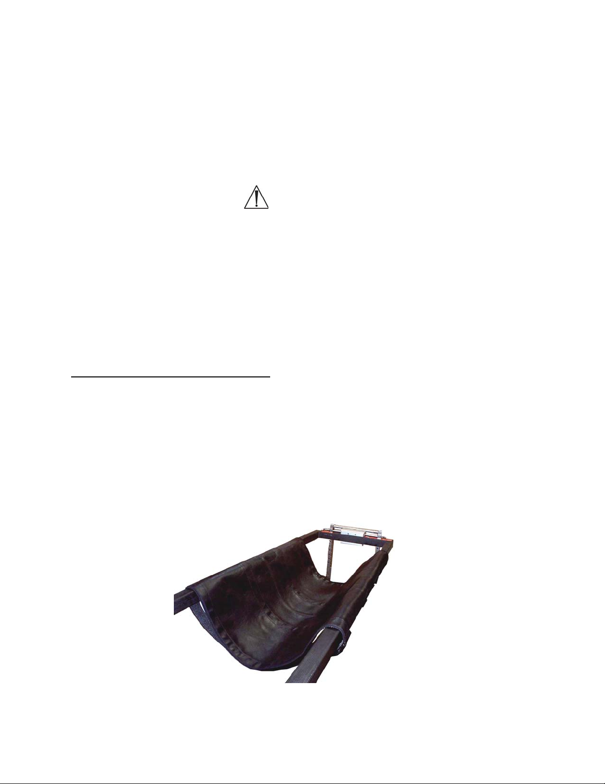
7.5.2 Acople los soportes apropiados para el paciente en el tablero par a cirugía
de la columna Jackson. Gire el seguro y engánchelo al poste de fijación
para fijar los soportes. Una vez instalados, confirme que los seguros
estén bien enganchados (figuras 33 y 34).
NOTA: Para lograr la correcta colocación final de los soportes, puede que sea
necesario reposicionarlos a lo largo del bastidor de la mesa después de transferir al
paciente a ella. Para ello, levante con cuidado al paciente, suelte el seguro en la base
del soporte, deslice y coloque el soporte en su nueva posición y vuelva a enganchar
el seguro.
ADVERTENCIA:
Verifique que los seguros de los soportes estén bien enganchados. Si no se hace
lo anterior, las bases de los soportes podrían romperse mientras se transfiere
al paciente al (o desde el) tablero para cirugía de la columna Jackson.
7.5.3 Coloque el cojín facial GentleTouch® y las fundas para los soportes
torácico, de muslo y de cadera según se describe en las instrucciones del
kit auxiliar.
7.5.4 Acople al tablero los dos soportes para piernas o el cabestrillo para
piernas. Los soportes para piernas se muestran en las figuras 36 y 37;
el cabestrillo se muestra en la figura 38.
7.6 Uso del cabestrillo para piernas
En el tablero para cirugía de la columna Jackson, para sujetar las piernas en su lugar,
puede utilizarse el cabestrillo en lugar de los soportes para piernas (figura 38). Con el
cabestrillo para piernas es posible una mayor flexión de la cadera ya que se pueden
bajar las rodillas del paciente por debajo del bastidor del tablero para cirugía de la
columna Jackson. Cuando se utiliza el cabestrillo, se recomienda no utilizar los
soportes de cadera ya que el mayor ángulo de flexión de la cadera podría aumentar
la presión en la cara anterior de los muslos. En la figura 43 puede verse a un paciente
bien posicionado en un cabestrillo para piernas.
Figura 38: Cabestrillo para piernas
MIZUHOSI 2009 NW0504 Rev. D
33
Page 92

El cabestrillo debe ajustarse para cada paciente. Las correas del cabestrillo constan de
un cierre velcro por los dos lados que permite ajustarlas a lo largo de toda su longitud.
Para instalar el cabestrillo, colóquelo sobre el bastidor del extremo de los pies del
tablero de la columna. Pase las cuatro correas por sus hebillas respectivas en el lado
opuesto del cabestrillo y asegúrelas. El extremo de velcro de la correa puede doblarse
y sujetarse sobre la correa para un mejor ajuste. La correa puede doblarse sobre sí
misma de nuevo para acortarse y, de esta forma, elevar el cabestrillo y reducir el
ángulo de flexión de la cadera del paciente.
7.6.1 Coloque dos (2) o tres (3) almohadas en el cabestrillo aproximadamente
donde descansarán las pantorrillas del paciente para que la rodilla quede
flexionada según se desea. Esto puede también hacerse al utilizar los
soportes para piernas.
7.7 Selección del método para soporte de la cabeza
7.7.1 Antes de transferir al paciente a la mesa, el cirujano debe haber
seleccionado el método de soporte para la cabeza del paciente.
El método elegido determina el siguiente paso de la preparación.
Se dispone de cinco (5) opciones:
OPCIÓN 1 Soporte la cabeza del paciente con un cojín GentleTouch®, como el que
se incluye en el kit auxiliar (Mizuho OSI P/N 5808), junto con la placa de
soporte de la cabeza. Este cojín puede adquirirse por separado (Mizuho
OSI p/n 1937 ó 1927) (figura 39). Una vez que se saca del kit auxiliar, el
cojín tarda 20 minutos en expandirse totalmente.
Cojín GentleTouch®
Figura 39: Cojín GentleTouch® para posición prona
MIZUHOSI 2009 NW0504 Rev. D
34
Page 93
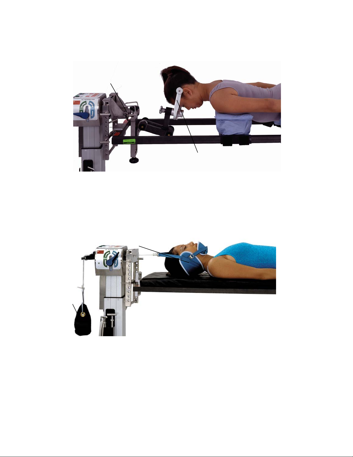
OPCIÓN 2 Utilice unas tenazas craneales o un reposacabezas en forma
de herradura junto con la unidad base de tratamiento cervical de Mizuho
OSI (5979-1) (figura 40).
Unidad base de tratamiento cervical
Tenazas craneales
Figura 40: Tenazas craneales acopladas a la unidad base de tratamiento cervical
OPCIÓN 3 Utilice un inmovilizador de cabeza. Mediante el hilo de tracción, aplique
tracción al inmovilizador de cabeza a través de unidad de polea en el
cabecero de la mesa (figura 41). Mediante pesas de arena, cuelgue el
peso deseado en un portapesas en el cabecero de la mesa.
Inmovilizador de cabeza
Pesa de arena
Figura 41: Tracción con el inmovilizador de cabeza
OPCIÓN 4 Utilice unas tenazas de Gardner-Wells aplicadas al cráneo del paciente
de acuerdo con las instrucciones del fabricante. Mediante el hilo de
tracción, aplique tracción a las tenazas a través de la unidad de polea en
el cabecero de la mesa. Mediante pesas de arena, cuelgue el peso
deseado en un portapesas en el cabecero de la mesa.
MIZUHOSI 2009 NW0504 Rev. D
35
Page 94

OPCIÓN 5 Si el paciente lleva un halo cervical, es posible acoplar algunos halos
directamente a la unidad base de tratamiento cervical de Mizuho OSI
(figura 42). Póngase en contacto con el fabricante del halo para
informarse sobre la disponibilidad y uso de adaptadores para halo.
Figura 42: Dispositivo de halo acoplado a la unidad base de tratamiento cervical
Dispositivo de halo
Adaptador de halo
Unidad base de tratamiento cervical
ADVERTENCIA:
Al utilizarse halos, tenazas o dispositivos de herradura, es absolutamente
necesario seguir los procedimientos recomendados por el fabricante.
NOTA: Se recomienda poner al paciente medias antiembólicas y medias de
compresión secuencial mientras está en posición de decúbito prono antes de la
intervención para fomentar el retorno venoso y reducir el riesgo de edema maleolar.
Esto debe hacerse siguiendo órdenes del médico responsable y de acuerdo con las
instrucciones del fabricante.
7.8 Transferencia del paciente
7.8.1 Coloque la camilla de transporte del paciente con éste paralelo al tablero
para cirugía de la columna Jackson. Antes de transferirse el paciente,
deben colocarse los soportes en una posición aproximada respecto a las
marcas de referencia anatómicas, es decir: la cresta ilíaca alineada con
el centro del soporte de cadera (figura 42).
7.8.2 Para que pueda transferirse al paciente con facilidad, levante la camilla
hasta que quede aproximadamente al mismo nivel que la superficie
superior de los soportes.
7.8.3 Gire al paciente sobre el tablero para cirugía de la columna Jackson en la
posición de decúbito prono, sujetando la cabeza, el torso y las piernas
durante la transferencia.
MIZUHOSI 2009 NW0504 Rev. D
36
Page 95

7.9 Posicionamiento de la cabeza
7.9.1 Soporte bien la cabeza del paciente mediante una de las cinco opciones
detalladas en el apartado 7.7.
7.10 Colocación de los brazos
7.10.1 Acople los apoyabrazos articulables al tablero para cirugía de la columna
Jackson. La abrazadera de montaje del apoyabrazos puede colocarse
encima o debajo de la placa de soporte de la cabeza; coloque el
apoyabrazos paralelo al tablero (figura 36).
7.10.2 Ponga los brazos en las férulas TLC incluidas en el kit auxiliar. Coloque
los brazos en los apoyabrazos articulables y sujételos con las correas de
cierre por contacto provistas. Los brazos deben estar flexionados
a la altura de los hombros no más de 90° y a la altura de los codos no
más de 90° (figura 43).
ADVERTENCIA:
La hiperextensión del hombro puede comprimir el plexo braquial y causar una
lesión nerviosa o vascular.
7.11 Posicionamiento del tórax
7.11.1 El soporte torácico debe estar en contacto con el paciente de manera que
el borde superior caiga en el hueco supraesternal del paciente. En el
posicionamiento ideal, el soporte torácico debe estar en contacto con el
paciente de manera tal que la carga sea soportada predominantemente
por la zona superior del tórax sobre el esternón. Esta posición impedirá
también que los pechos y los músculos soporten la carga primaria de la
parte superior del torso, y los protegerá. Cuando el tórax está en esta
posición, es más fácil lograr una respiración asistida adecuada para el
paciente. Para reposicionar el soporte torácico con un paciente en la
mesa, levante un poco al paciente y deslice el cojín a lo largo del bastidor
hasta llegar al lugar deseado. Descanse de nuevo y con cuidado al
paciente sobre el soporte. Confirme que la funda del soporte torácico esté
bien colocada, sin dobleces ni arrugas.
ADVERTENCIA:
El posicionamiento del soporte torácico superior al hueco supraesternal podría
hacer presión sobre la garganta y las vías respiratorias del paciente.
MIZUHOSI 2009 NW0504 Rev. D
37
Page 96

7.12 Colocación de las caderas y los muslos
7.12.1 Ajuste los soportes de cadera de manera que queden debajo de las
crestas ilíacas. Las crestas ilíacas deben estar centradas en los soportes
de cadera (figura 43).
Cresta ilíaca centrada en el soporte de cadera
Correa de las nalgas
Almohadas
Correa
de seguridad
Correa
de seguridad
Cabestrillo
para piernas
Figura 43: Paciente en decúbito prono en el tablero para cirugía de la columna
con el cabestrillo para piernas
Almohadas Correa de las nalgas
Figura 44: Paciente colocado en decúbito prono en el tablero de cirugía de la columna utilizando
Correa
de seguridad
los soportes para piernas
Correa
de seguridad
MIZUHOSI 2009 NW0504 Rev. D
38
Page 97

NOTA: Los soportes de muslo están diseñados para las piernas izquierda y derecha,
y están etiquetados correspondientemente. Cuando el paciente se coloca en decúbito
prono, los soportes de muslo deben estar orientados hacia él. Los soportes de muslo
tienen un ángulo compuesto que proporciona un soporte anatómico a las piernas.
Confirme que los soportes estén colocados en el lado adecuado del tablero para cirugía
de la columna. Cuando los soportes están correctamente colocados, su pendiente debe
disminuir en dirección al piecero de la mesa.
7.12.2 Los soportes de muslo deben tocar el borde distal de los soportes de
cadera y deben descansar debajo de los muslos del paciente (figura 36).
Una vez ajustados los soportes en el sitio adecuado, el cirujano debe
levantar con cuidado al paciente en el lugar de contacto con cada soporte
para alisar la superficie de contacto.
7.12.3 Confirme que todos los seguros de los soportes estén bien enganchados.
7.13 Colocación de las piernas
7.13.1 Posicione las piernas en los soportes para piernas o en el cabestrillo para
piernas según se desee. Cuando se utilice el cabestrillo, ponga dos (2) o
tres (3) almohadas debajo de las rodillas y las tibias del paciente para
ayudar a reducir la presión sobre estas zonas. Compruebe que los pies
del paciente no estén tocando ninguna superficie de la mesa.
NOTA: Para acomodar a un paciente alto en el tablero de la columna, puede resultar
ventajoso utilizar el cabestrillo para piernas ya que así se permite una mayor flexión de
las caderas y rodillas.
7.13.2 Ponga una manta sobre los pies hasta la zona glútea para combatir la
posibilidad de hipotermia. Pueden colocarse almohadas extra bajo los
pies y las pantorrillas para aumentar el ángulo de flexión de las rodillas
y para que los pies no toquen el tablero ni la base.
NOTA: Debido al diseño abierto del tablero para cirugía de la columna Jackson y a la
larga duración de las intervenciones de columna, debería considerarse y se
recomienda el uso de calentadores de aire a presión, calentadores de líquido y mantas
como medio para combatir la hipotermia. Las mantas pueden colocarse sobre los pies
hasta la zona glútea y sobre los hombros y los brazos fuera del campo quirúrgico para
mantener la temperatura corporal del paciente. Estos dispositivos deben utilizarse de
acuerdo con las instrucciones del fabricante y bajo las órdenes del médico responsable.
MIZUHOSI 2009 NW0504 Rev. D
39
Page 98

7.13.3 Coloque la correa de las nalgas a través de la zona glútea inferior. Esta
correa debe colocarse en dirección cefálica con respecto a los soportes
de cadera alrededor del bastidor de la mesa, hasta alcanzar la hebilla
correspondiente. Confirme que la correa de las nalgas quede en la parte
baja de la zona glútea, rodee los dos soportes de cadera y esté bien
ceñida alrededor de las nalgas. Puede utilizarse una manta debajo de la
correa de las nalgas a fin de proteger al paciente del contacto directo con
la correa de seguridad.
7.13.4 Coloque una correa de seguridad (152 cm) sobre las pantorrillas del
paciente y alrededor del bastidor, y sujétela con la hebilla. La correa debe
estar lo suficientemente apretada como para mantener sujetas las piernas
contra las almohadas si la mesa se inclina lateralmente. Coloque una
correa de seguridad (228 cm) alrededor del torso del paciente, del soporte
torácico y de la mesa, y sujétela con la hebilla (figura 43).
7.13.5 Prepare y cubra con sábanas al paciente en la forma habitual. Tome
medidas para que el preparado no fluya ni se acumule debajo del
abdomen del paciente ni sobre los componentes de la mesa.
7.13.6 Si se desea, el cirujano puede ajustar con ayuda del mando de mano la
altura de la mesa, Trendelenburg y Trendelenburg inverso con el paciente
colocado en la mesa. (La inclinación lateral puede ajustarse mediante el
mando de mano sólo en la base de control avanzado 5892/5803.)
Consulte el manual del usuario de la base para mesa modular adecuado
para las instrucciones completas sobre cómo utilizar estas funciones.
MIZUHOSI 2009 NW0504 Rev. D
40
Page 99

8.0 PROCEDIMIENTOS DE ROTACIÓN
Gracias al diseño exclusivo de la mesa para cirugía de la columna Jackson, el cirujano
puede rotar al paciente de forma segura sobre el eje horizontal. Esta capacidad rotativa
proporciona muchas ventajas especiales, entre ellas la posibilidad de usar técnicas de
imágenes específicas de las que hasta ahora no se disponía. Por ejemplo, es posible
realizar una rotación de 360° sin mover al paciente de la mesa, lo cual permite realizar
procedimientos quirúrgicos por vía anterior y posterior durante la misma intervención.
8.1 Rotación lateral o inclinación lateral intraoperatoria
Para rotar lateralmente a un paciente con un brazo en C colocado mientras se le
examina con fluoroscopia, se deben seguir los siguientes pasos:
8.1.1 Sujete el paciente a la mesa tal como se describe en el apartado 5.0,
“Colocación en posición supina para procedimientos y cirugía de la
columna por vía anterior”, o en el apartado 7.0, “Colocación en decúbito
prono para procedimientos y cirugía de la columna por vía posterior”.
ADVERTENCIA:
No se recomienda girar lateralmente al paciente más de 25° si no tiene colocadas
correas de seguridad en el tórax y en las extremidades inferiores. El paciente
podría caerse si se le gira lateralmente más de 25° sin las correas de seguridad.
ADVERTENCIA:
Salvo que se esté utilizando el tablero lateral Mizuho OSI Maximum Access™, no
deberá girarse lateralmente al paciente más de 25°.
MIZUHOSI 2009 NW0504 Rev. D
41
Page 100

8.2 Bases para mesa modular 5890/5891
1. Confirme que los frenos de las cuatro (4) ruedas giratorias estén accionados.
2. Confirme que el tope de rotación de 25° esté accionado.
3. Confirme que los controles de fricción durante la rotación estén en la posición de
máxima fricción. De pie a un lado de la mesa, agarre firmemente ambos lados de la
mesa para prevenir la rotación no deseada debido a una carga asimétrica del
paciente.
4. Desactive los bloqueos de seguridad para la transferencia del paciente en el
cabecero y el piecero. (Para desactivar estos bloqueos, puede que sea necesario
aflojar un poco los controles de fricción durante la rotación en el cabecero y en el
piecero).
5. Libere los controles de fricción durante la rotación en el cabecero y en el piecero
hasta que la mesa pueda moverse. Gire el tablero hasta que se tenga la vista
radiológica deseada.
6. Apriete los controles de fricción durante la rotación en el cabecero y en el piecero.
8.3 Bases de control avanzado 5892/5803
1. Confirme que los frenos de las cuatro (4) ruedas giratorias estén accionados.
2. Confirme que la luz de seguridad de la rotación esté iluminada.
3. Confirme que la palanca de bloqueo de la rotación de 180° esté en la posición
de bloqueo.
4. Un asistente en el cabecero de la mesa deberá pulsar el botón de inclinación
a derecha o a izquierda adecuado en el mando de mano para girar lateralmente
el tablero hasta que se logre la vista radiológica deseada.
NOTA: El indicador de accionamiento de la inclinación en la base 5892/5803 dejará
de estar iluminado una vez que la mesa se gire lateralmente y deje de estar en la
posición neutra.
ADVERTENCIA:
El paciente podría caerse si no se siguen los procedimientos prescritos acerca
del uso de los controles, bloqueos y correas de seguridad para el paciente.
8.4 Rotación del paciente de 180°
La secuencia de rotación de 180° del paciente está diseñada para poder girar
completamente a un paciente desde la posición supina a la posición prona, y viceversa.
Esto sólo puede lograrse después de la secuencia de colocación descrita en el
apartado 5.0, “Colocación en posición supina para procedimientos y cirugía de la
columna por vía anterior”. En la mayoría de los casos, se volverá a posicionar al
paciente para la cirugía de columna por vía posterior después de finalizar la cirugía por
vía anterior (esto es, se le cambiará de una posición supina a una prona).
MIZUHOSI 2009 NW0504 Rev. D
42
 Loading...