

Page 1
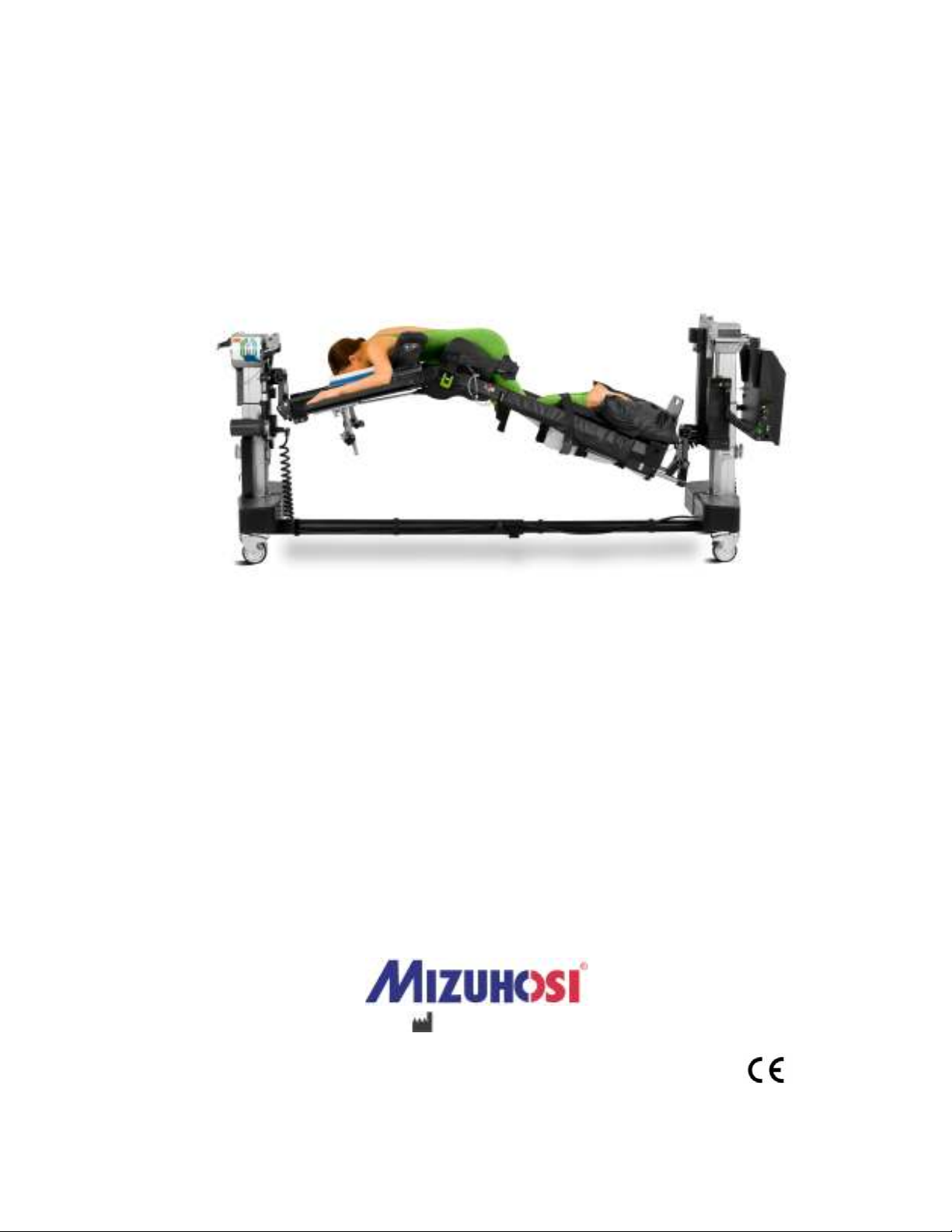
AXIS JACKSON SYSTEM ®
OWNER’S MANUAL
Model 6977
This manual is written in five
languages in the following order:
• (en) English
• (es) Spanish
• (fr) French
• (de) German
• (it) Italian
MIZUHO OSI
30031 AHERN AVENUE • UNION CITY, CA 94587
Bus: 510-429-1500 • Toll Free: 800-777-4674 Fax: • 510-429-8500
WWW.MIZUHOSI.COM ·
•
NEWHIPNEWS.COM · •NEWSPINENEWS.COM
MIZUHOSI 2009 1 NW0507 Rev G
Page 2

© Copyright 2008, Mizuho OSI. All rights reserved.
Information in this document is subject to change without notice. Mizuho OSI assumes
no responsibility for any errors that may appear in this document. This document is
believed to be complete and accurate at the time of publication. In no event shall
Mizuho OSI be liable for incidental, special, multiple, or consequential damages in
connection with or arising from the use of this document.
NOTICE TO PURCHASER:
MIZUHOSI®, Axis Jackson®, Axis Jackson System®, GentleTouch®, Torso Trolley®,
Advance Control Pad System™, and IVSP™ are trademarks of Mizuho OSI and the
Mizuho Corporation.
The Axis Jackson System® Model 6977 is a Class II, Exempt Device within the
guidance of 21 CFR Part 860 Medical Device Classification Procedures. The 6977 is
Class I, in accordance with Rule I of the Medical Device Directive Guidance Document
MDDEV 2.4/1, Guidelines for the Classification of Medical Devices.
The Axis Jackson System® Model 6977 is intended for use as a patient positioning
surgical support system for thoracic and lumbar spine procedures. It provides for a wide
range of intra-operative angular movement with the patient positioned prone, supine, or
lateral. Patent pending.
All other trademarks in this document are the sole property of their respective owners.
Printed in the USA, 2009
MIZUHOSI 2009 2 NW0507 Rev G
Page 3

AXIS JACKSON SYSTEM
TABLE OF CONTENTS
Section Page
1.0 SAFETY INFORMATION ..................................................................................... 4
2.0 INTRODUCTION .................................................................................................. 8
3.0 SYSTEM COMPONENTS .................................................................................. 11
4.0 AXIS JACKSON SYSTEM SET-UP................................................................... 14
5.0 PRE-OPERATION FUNCTION CHECKS .......................................................... 34
6.0 OPERATING THE SYSTEM .............................................................................. 36
7.0 PRONE POSITIONING ...................................................................................... 41
8.0 SUPINE AND LATERAL POSITIONING ........................................................... 56
9.0 CLEANING, STORAGE, AND ROUTINE MAINTENANCE............................... 64
10.0 TROUBLESHOOTING GUIDE........................................................................... 68
11.0 REPAIR AND TECHNICAL SERVICE............................................................... 75
12.0 CONTACTING MIZUHOSI ................................................................................. 76
13.0 6977 ELECTRICAL INTERCONNECT DIAGRAM (PAGE 1 OF 2)................... 77
14.0 STANDARD COMPONENTS AND OPTIONAL ACCESSORIES...................... 79
15.0 AXIS JACKSON SYSTEM® OWNER’S MANUAL CHECKLIST ..................... 85
MIZUHOSI 2009 3 NW0507 Rev G
Page 4

1.0 SAFETY INFORMATION
CAUTION
WARNING
DANGER
CAUTION
Safety Conventions Used In This Document
Document Five user attention words may appear in the text of this Mizuho
User Attention OSI Owner’s Manual. Each user attention word implies a
Words particular level of observation or action as described below.
Note: Calls attention to useful information.
IMPORTANT: Indicates information that is necessary for proper product operation.
Indicates a potentially hazardous situation which if not avoided may
result in minor or moderate injury. It may also be used to alert against
unsafe practices.
Indicates a potentially hazardous situation which if not avoided could
result in death or serious injury.
Indicates an imminently hazardous situation which if not avoided will
result in death or serious injury. This signal word is to be limited to the
most extreme situations.
Before Ensure that everyone involved with the use or maintenance
Using This of this product has read the Owner’s Manual.
Product
Avoid using this product in a manner not specified by Mizuho OSI.
IMPORTANT: The positioning techniques and applications outlined in this manual are
the manufacturer’s suggested techniques. The final disposition of
each patient’s care as related to the use of this product rests with the
attending physician.
MIZUHOSI 2009 4 NW0507 Rev G
Page 5
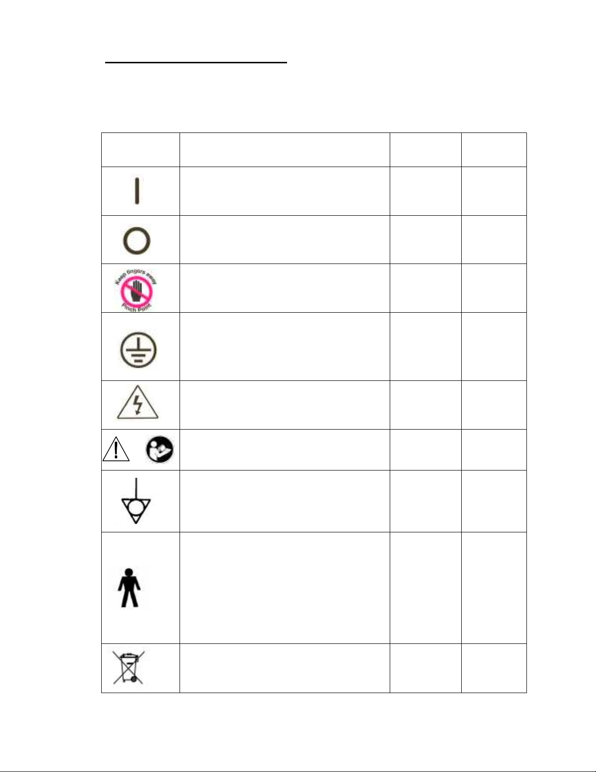
Safety and Health Symbols Used
The following Table (T-1) describes the symbols displayed on the Axis
Jackson System and referenced within this Owner’s Manual.
Table T-1
Symbol
Indicates pinch point.
Indicates a protective grounding terminal
Indicates the presence of an electrical
Indicates the ON position of a power
switch.
Indicates the OFF position of a power
switch.
that must be connected to earth ground
before any other electrical connections
are made to the product.
shock hazard and to proceed with
appropriate caution.
Description
Used On
Product
√
√
√
Used In
Manual
√
√
Indicates that you should consult the
OR
manual for further information and to
proceed with appropriate caution.
Indicates an external ground stud that is
required for use when the AC power
cable is not connected to a protective
earth ground outlet in your operating
room or facility.
Indicates this equipment is an applied
part, TYPE B in accordance with IEC
60601-1 and is generally suitable for
applications involving external or internal
contact with the patient, excluding the
heart. The patient circuit is connected to
protective earth and this equipment
should be connected only to outlets with a
protective earth ground.
Indicates Waste Disposal information.
√
√
√
√
MIZUHOSI 2009 5 NW0507 Rev G
Page 6
Product Safety Certifications
CAUTION
WARNING
The Axis Jackson System has been independently tested and verified to comply with
the applicable sections of the following:
IEC 60601-1 Medical Electrical Equipment, Part 1: General Requirements for Basic
Safety and Essential Performance.
IEC 60601-1-2 Medical Electrical Equipment, Part 1-2: General Requirements for Safety
– Collateral Standard: Electromagnetic Compatibility – Requirements and Tests.
IEC 60601-2-46 Medical Electrical Equipment – Part 2: Particular Requirements for
Safety – Specification for Operating Tables.
UL60601-1 UL Standard for Safety for Medical Electrical Equipment, Part 1: General
Requirements for Safety.
CAN/CSA C22.2 NO. 601.1-M90 Medical Electrical Equipment - Part 1: General
Requirements for Requirements for Safety.
JIS0601-1 Medical Electrical Equipment, Part 1: General Requirements for Safety.
93/42/EEC Medical Device Directive.
IEC 60529 Degrees of Protection Provided by Enclosures (IP Code).
General Product Setup and Use Precautions
Servicing of the Axis Jackson System is to be performed only by
Mizuho OSI Factory authorized personnel. Failure to comply with
this requirement may result in damage to the product, and injury or
death of personnel.
This equipment is an applied part, TYPE B, in accordance
with IEC 60601-1 and is generally suitable for applications involving
external or internal contact with the patient, excluding the heart.
The patient circuit is connected to protective earth and this
equipment should be connected only to outlets with a protective
earth ground.
MIZUHOSI 2009 6 NW0507 Rev G
Page 7

An external ground stud is required for use when the AC
WARNING
power cable is not connected to a protective earth ground outlet in
your operating room or facility. To protect the patient and hospital
staff from any possible hazards, an external ground wire connection
is required between the external ground stud and protective earth
ground. Failure to comply with this requirement may result in
damage to the product, and injury or death of personnel.
IMPORTANT: Medical electrical equipment needs special precautions regarding EMC
and needs to be installed and put into service according to the EMC
information provided in this manual.
IMPORTANT: Portable and mobile RF communications equipment can affect medical
electrical equipment.
IMPORTANT: This equipment should not be stacked with other equipment. The
equipment should be observed to verify normal operation in the
configuration in which it will be used.
IMPORTANT: The use of accessories, transducers and cables that are not specified
by Mizuho OSI, may result in increased electrical/electronic signal
emissions and/or decreased electronic/electrical signal immunity which
may affect the proper operation of the equipment.
Note: To be in compliance with the European WEEE Directive, all
electrical components, batteries and carbon composite components
that must be disposed shall either be returned directly to Mizuho OSI
or to a Mizuho OSI specified disposal facility for proper disposal.
Please contact Mizuho OSI Customer Resources Department at 1800-777-4674 for further information regarding this requirement.
MIZUHOSI 2009 7 NW0507 Rev G
Page 8

2.0 INTRODUCTION
General Description
The Mizuho OSI Axis Jackson System®, Model 6977, in conjunction with the Mizuho
OSI Advanced Control Modular Table Base, Model 5803 is a patient positioning surgical
support system for thoracic and lumbar spine procedures that provides for a wide range
of intra-operative angular movement.
The Axis Jackson System can be set-up for prone, supine and lateral patient positioning
and is designed to articulate the patient intra-operatively in flexion and extension,
replicating the natural movement of the spine.
The Axis Jackson Hinged Frame is designed to only be mounted on the Mizuho OSI
5803 Advanced Control Modular Table Base. The modular base Hand Pendant controls
the Trendelenburg, Reverse Trendelenburg, and table top height adjustments. The
Hand Pendant for the Axis Jackson controls the table top’s Hinge movement and
Lateral Roll.
The Axis Jackson System incorporates an Advance Control Pad System (ACP) which
supports a patient in the prone position. The pad system is electronically controlled and
pneumatically actuated, providing massage action and periodic pressure point
stimulation through the Bilateral Winged ACP Chest Pad and the Contoured
Combination ACP Hip / Thigh Pads.
Specifications
Hinged Frame 80“ (203 cm)
Total Length
Hinged Frame Head-End 33“ (84 cm) length
Hinged Frame Foot-End 47” (119 cm) length
Hinged Frame Head-End 19“ (48 cm) width
Hinged Frame Width
Hinged Frame Foot-End 19” (48 cm) width
Head-End 30“ (76 cm) length
Two Piece Supine Top Length
Foot-End 43“ (109 cm) length
Head-End 21” (53 cm) width
Supine Top Width
Foot-End 21” (53 cm) width
-20° (± 2°) Hinge Down
Table Articulations
+35° (± 2°) Hinge Up
12° (± 2°) Lateral Roll
Table Top Height Range
24” – 39” (61 cm - 99cm) measured at the HeadEnd of the table frame
Patient Weight Capacity 500 lb (227 kg) maximum
Power Requirements 6977: 100-230 VAC at 50/60 Hz, 9 Amps max.
Duty Cycle of Hinged Frame 10%, (6 minutes continuously per hour)
MIZUHOSI 2009 8 NW0507 Rev G
Page 9

Product Acceptance
Upon receipt of your Axis Jackson System, remove each component from its shipping
crate or packaging. Visually inspect all surfaces for freight damage.
Note: Any freight damage must be reported to the freight carrier immediately upon
delivery. It is the responsibility of the recipient to make freight damage claims.
Glossary of Terms
Foot Elevator, Down A downward motion of the Hinged Frame Foot-End. The
Hinge angle remains neutral.
Foot Elevator, Up An upward motion of the Hinged Frame Foot-End. The
Hinge angle remains neutral. The Foot-End of the frame
does not raise above neutral.
Foot-End Table Top The section of the Hinged Frame where the Removable
Foot Board is attached.
Head-End Table Top The section of the Hinged Frame where the Torso
Trolley® mounts.
Height Down Both Columns of the modular base lower simultaneously
to lower the table top.
Height Up Both Columns of the modular base raise simultaneously
to raise the table top.
Hinge Down The Hinge of the frame moves downward. The Foot
elevator moves upward.
Hinge Up The Hinge of the frame moves upward. The Foot
Elevator moves downward.
Lateral Roll, Left A counter-clockwise motion of the table top about its
longitudinal axis, as viewed from the Head-End Column.
Lateral Roll, Right A clockwise motion of the table top about its longitudinal
axis, as viewed from the Head-End Column.
Left Side of Table Top The left side of the table top, as viewed when standing
at the Head-End Column facing the Foot-End Column.
Return to Home The Hinged Frame returns to level side to side and the
Hinge and Foot Elevator return to neutral positions.
Reverse Trendelenburg A position of the table top and the patient, with the Foot-
End lower than the Head-End. On the modular base,
the Head-End Column raises and the Foot-End Column
lowers simultaneously. If the table is in a fully raised
position, only the Foot-End will lower to achieve the
proper Reverse Trendelenburg angle.
Right Side of Table Top The right side of the table top, as viewed when standing
at the Head-End Column facing the Foot-End Column.
MIZUHOSI 2009 9 NW0507 Rev G
Page 10

Trendelenburg
A position of the table top and the patient, with the Head-End
lower than the Foot-End. On the modular base, the Foot-End
Column raises and the Head-End Column lowers
simultaneously. If the table is in a fully lowered position, only
the Foot-End will raise to achieve the desired Trendelenburg
angle.
V Hinge Down Only the Hinge of the frame moves downward.
V Hinge Up Only the Hinge of the frame moves upward.
MIZUHOSI 2009 10 NW0507 Rev G
Page 11
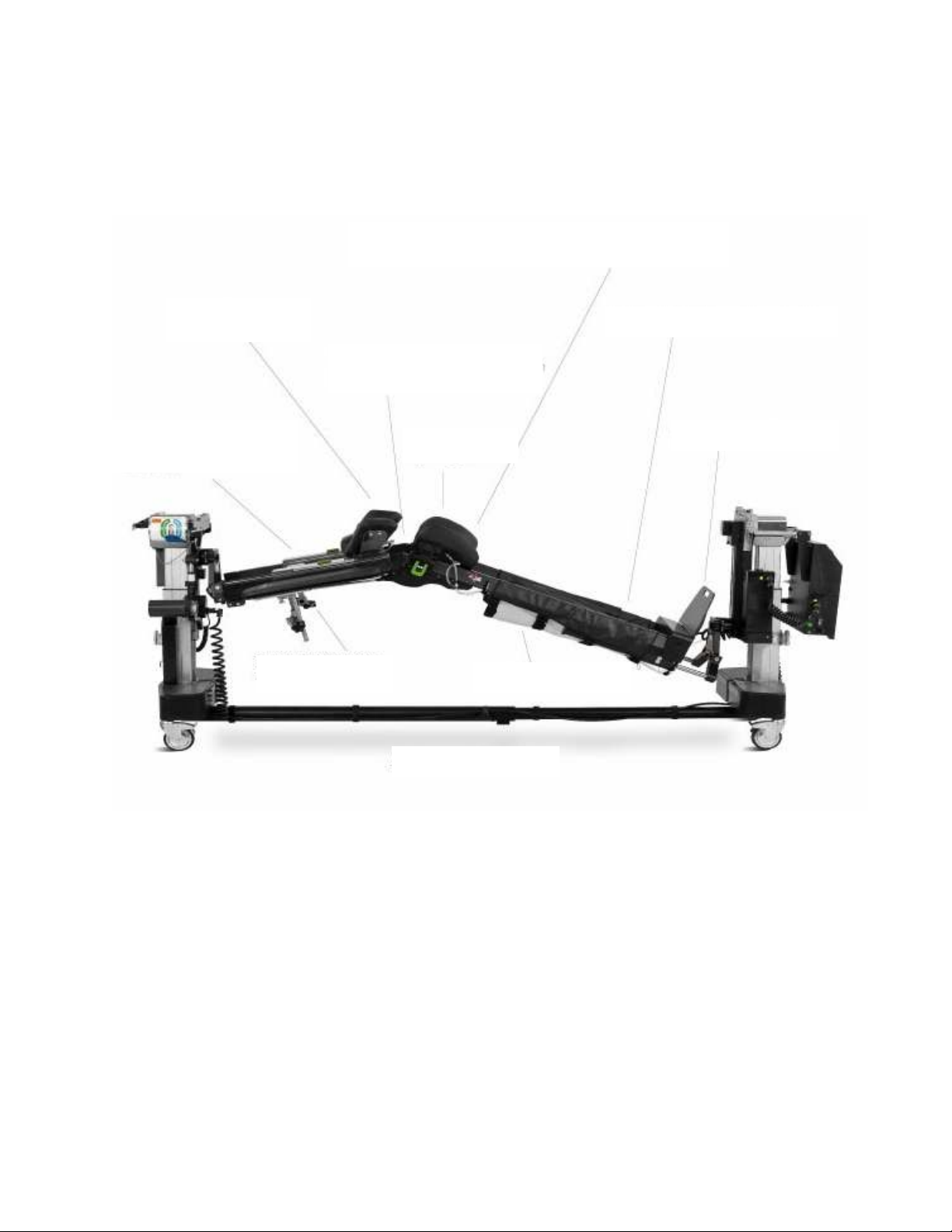
3.0 SYSTEM COMPONENTS
Advanced Control Pad System™ (ACP)
Hinged Frame
Contoured
Bilateral Winged
Torso Trolley™
5-Way Adjustable
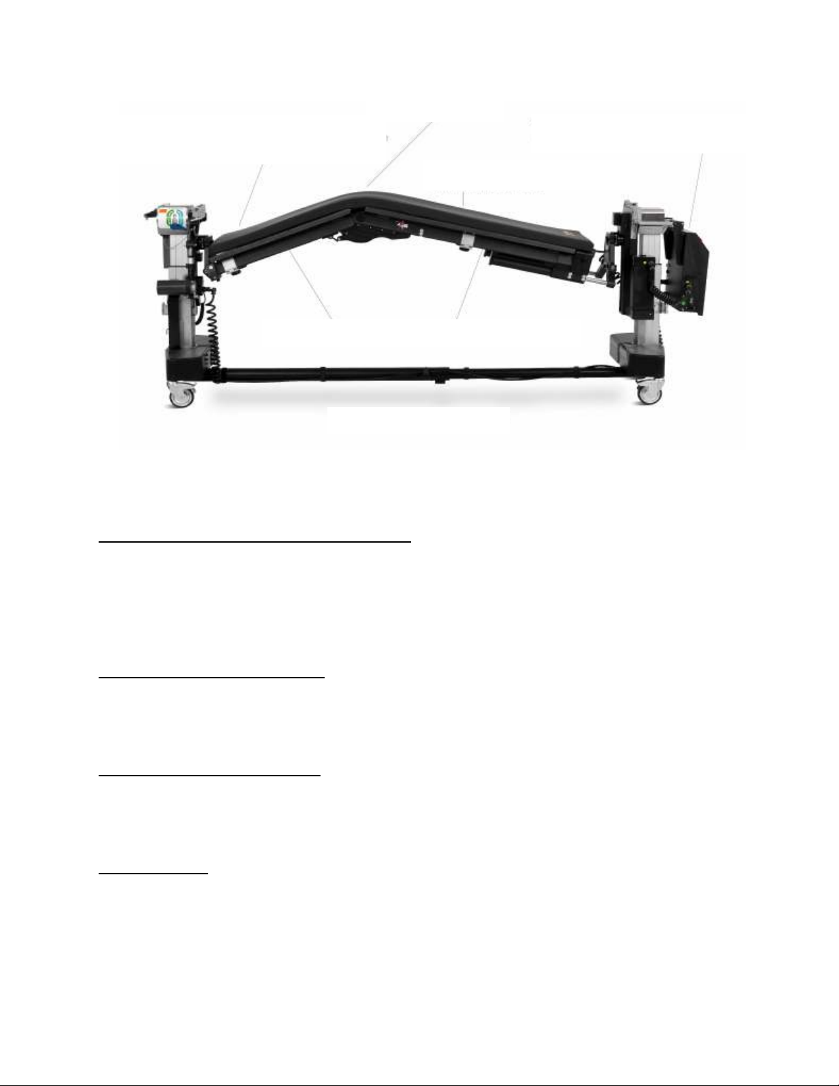
The main components of the Axis Jackson System are shown in Figures 1 and 2.
– automatically
stimulates patient pressure points on chest, hips and thighs
Chest Pad
- integrates
patient movement with hinge
translation
Arm Boards
Carbon Fiber Frame Construction
– supports spine
biomechanics and improves
surgeon access
Removable Foot Board
Hip/ Thigh Pads
Adjustable Leg Sling
Hinged Frame
6977 Axis Jackson Hinged Frame with 5803 Advanced Control Modular Base
MIZUHOSI 2009 11 NW0507 Rev G
Figure 1: Axis Jackson System
Page 12
Axis Jackson™ System Controller
Tempur
-
Med® 2
-
in, Table Pad
P
rone and Supine Table Tops
–
mount on dual column 5803 Advanced Control
Base
Hinge Angle Plus 35°
with Translation Slide
-
controls hinged frame
Carbon Fiber Removable Two Piece Imaging Top
Two Piece Supine Top
Figure 2: Axis Jackson System
6977 Axis Jackson Hinged Frame w/Two-Piece Supine Top and 5803 Advanced Control Modular Base
Head-End and Foot-End Column Sliders
The Axis Jackson System cannot be used without first installing both the Head-End and
Foot-End Column Sliders. The Column Sliders (P/N 6977-640 & 6977-641) are key
structural components of the system. The Column Sliders mount on the 5803 Advanced
Control Base Head-End and Foot-End Columns.
Head-End Support Assembly
The Head-End Support Assembly (P/N 6977-601) attaches to the Head-End Column
Slider and provides structural support for the Hinged Frame.
Foot-End Support Assembly
The Foot-End Support Assembly (P/N 6977-600) attaches to the Foot-End Column
Slider and provides structural support for the Hinged Frame.
Hinged Frame
The Hinged Frame (P/N 6977-100) is the primary structural member of the Axis
Jackson. It directly supports the patient weight while articulating about the Hinge point
just above the patient’s hips. The frame is constructed of carbon fiber tube elements
with aluminum Hinge and end fittings, and it includes a length-compensation element to
handle the foreshortening of the frame when it is flexed. The Hinge drive motor is
incorporated into the Hinged Frame.
MIZUHOSI 2009 12 NW0507 Rev G
Page 13

Axis Jackson Controller with Cable Set
The Controller (P/N 6977-4006, 120V or 6977-4005I, 230V) supplies power to the
various components of the Axis Jackson System. The table top On/Off switch is located
on the Controller. The Controller also includes the air pump and controls for the
Advance Control Pad System (ACP).
Hand Pendant with Junction Box
The Axis Jackson Hand Pendant (P/N 6807-5) mounts in the Holster (P/N 6977-4162)
with the 5803 Advanced Control Base Hand Pendant and should be hung on the HeadEnd Column of the base for easy access. It is used to manipulate the Hinge of the
frame up and down as well as control Lateral Roll of the Hinged Frame.
Two-Piece Supine Imaging Top
The Two-Piece Supine Top (P/N 6977-955 and P/N 6977-956) is of carbon fiber
construction and mounts above and below the Hinge of the frame to allow for
articulation of the Hinge when the patient is positioned in the supine or lateral position.
A 2” (5 cm) MIZUHO OSI Tempur-Pedic® pad (P/N 6977-7000) is provided for use with
the Two-Piece Supine Imaging Top. The TEMPUR® used in the manufacture of
MIZUHO OSI pads has viscoelastic properties and is a temperature sensitive material,
becoming softer where the patient’s body is making the most contact with the surface
and remaining firm in areas where less body contact is being made. Pressure is
distributed evenly over the entire surface area. The pad is radiolucent, MR safe and
latex free. The benefits of using MIZUHO OSI Tempur-Pedic are improved pressure
management, reduced shear forces and enhanced patient comfort.
The Supine Top Translation Sheet (P/N 6977-927) interfaces with the Supine Top and
Tempur-med® Pad to allow support and movement.
MIZUHOSI 2009 13 NW0507 Rev G
Page 14

4.0 AXIS JACKSON SYSTEM SET-UP
IMPORTANT: It is recommended that two people work together when installing
or uninstalling the system components.
Note: If you have purchased a 6977 Axis Jackson System already mounted on a
5803 Advanced Control Base at the factory, the base has been prepared and
the frame mounted. It remains important, however, that Section 4.0 Axis
Jackson System Set-Up be read to form an understanding about how the
applicable components are installed and function.
The Mizuho OSI Axis Jackson System is designed to only mount and be utilized on the
5803 Advanced Control Modular Table Base.
Note: For complete instructions on the 5803 Advanced Control Modular Table Base
operation and functions, please refer to the Owner’s Manual supplied with the
Advanced Control Modular Table Base (P/N NW0498). A thorough
understanding of the operation of the 5803 Advanced Control Base is required
before continuing.
Preparing the 5803 Advanced Control Base for Mounting 6977 Axis Jackson System
Complete the following steps prior to mounting the Axis Jackson® Hinged Frame
1. Move and position the 5803 Advanced Control Base where it will be used.
2. Ensure the retractable I beam is fully extended and locked in place
Rotation Safety
Lock Switch / Indicator
Light
Tilt Drive Status
Indicator Light
Traction Pulley
180° Rotation Lock
Indicator Light
Crossbar
180° Rotation
Lock Lever
Figure 3A: Indicator Lights on the Head-End Column of 5803 Advanced Control Base
3. Lock all 4 caster locks on the base
MIZUHOSI 2009 14 NW0507 Rev G
Page 15
4. Verify the Head-End and Foot-End crossbars are level, that the Rotation Safety Lock
Switch is in the ON position, and the 180 degree Rotation Lock Lever is in the locked
position. All three indicator lights on the Head-End Column must be lit (the 180°
Rotation Lock Indicator light, the Tilt Drive Status light and the Rotation Safety
Indicator light).
5. Using a hex wrench, remove the H-frame storage brackets which are mounted on
the base of both the Head-End Column and the Foot-End Column of the 5803 Base.
This is required to allow for installation of the Column Sliders (P/N 6977-640, 6977-
641). The H-frame storage brackets can be re-attached should you desire when not
utilizing the Axis Jackson System
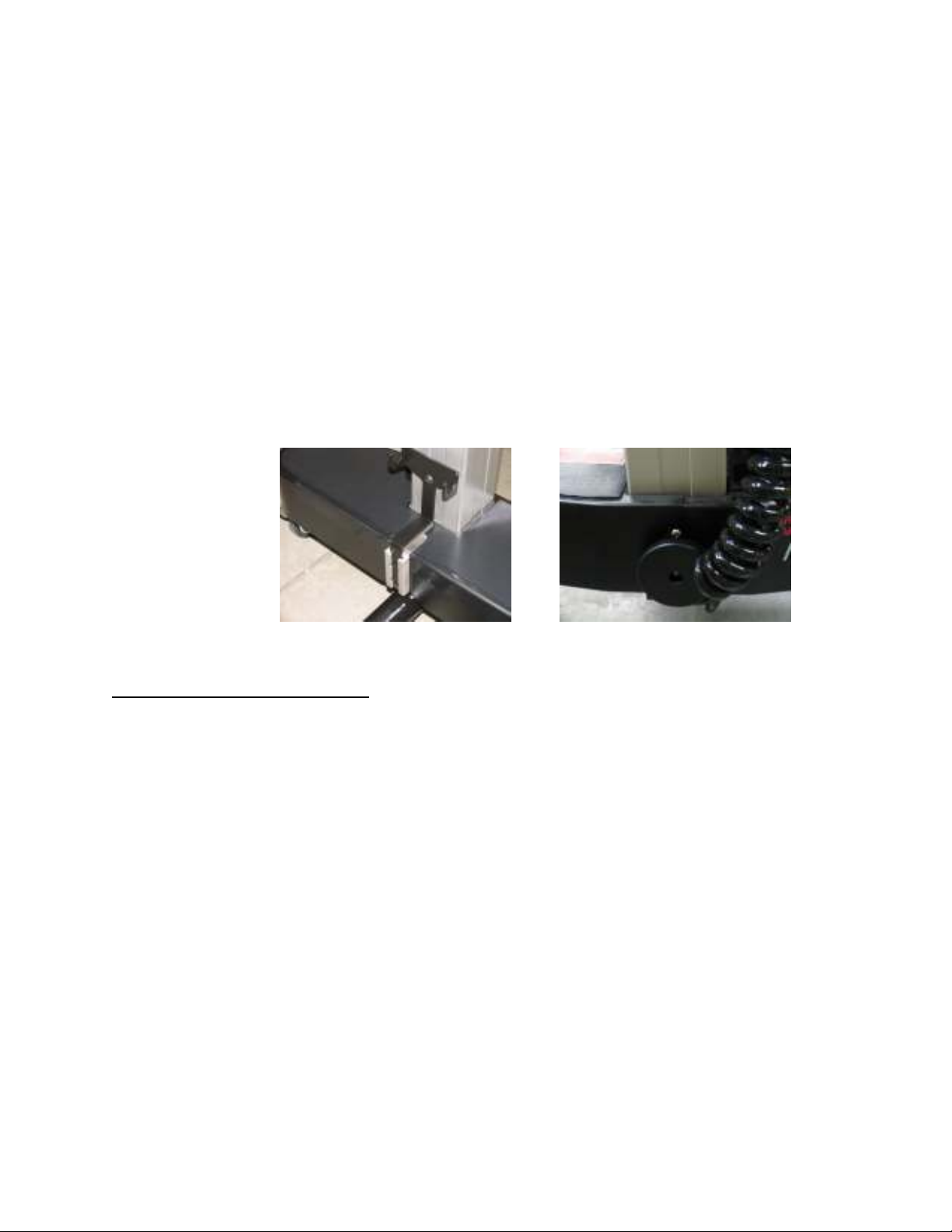
6. Where the brackets were removed, install the Table Base Joint Cover (P/N 6977-
853) and the H-Frame Hangar Bracket (P/N 6977-852) provided in the Axis Jackson
Conversion Kit (P/N 6977-850). Also provided in the kit is the Cable Attachment
Post (P/N 6977-209) and mounting hardware, install at the foot end of the 5803
base, location as shown in 3B below.
Figure 3B
Installing the Column Sliders
To attach the Column Sliders to the Head-End and Foot-End Columns of the 5803
base, complete the following steps:
1. Ensure the base has been prepared for mounting the Axis Jackson as instructed in
the previous section.
2. Ensure all 3 indicator lights on the Head-End Column are illuminated. If not, refer to
the 5803 Advance Control Base Owner’s Manual and complete the steps required.
3. Depress the Height Up button on the 5803 Base Hand Pendant and raise the
Columns of the base to half-way in their height range
4. Unlatch the Head-End Column Slider and slide between the quiver and the Column.
The Column Slider will rest on the foot of the modular base. Enclose the Column
with the Slider, latch and tighten the knob.
5. Unlatch the Foot-End Column Slider and slide between the quiver and the Foot-End
Column. The Column Slider will rest on the foot of the modular base. Enclose the
Column with the Slider, latch and tighten the knob.
MIZUHOSI 2009 15 NW0507 Rev G
Page 16

6. When installed correctly, the labels on the Column Sliders will be legible as shown
WARNING
below.
Figure 4: Installing the Column Sliders
Installing the Head-End Support Assembly
To install the Head-End Support Assembly, complete the following steps:
1. Lift the Head-End Support Assembly’s catch mechanism up under the Head-End
Column crossbar.
2. Align the catch with the dowel pins on the cross bar and install a T-pin (P/N 5840-
361) to secure it in place.
3. To attach the Head-End Support Assembly to the Head-End Column Slider, slide the
latch mechanism to engage the pin on the back side of the assembly. An audible
“click” confirms the latch mechanism is secured in place.
T-pin (handle end)
Figure 5: Installing the Head-End Support Assembly
T-pin (drop lock end)
Verify that the T-pin is inserted and passes completely through the
Head-End Support Assembly and Crossbar. Verify the T-pin drop lock
is in sight and pivots freely (see Figure 5 illustration). Failure to do so
may result in the patient and table assembly being dropped and may
result in serious injury to the patient and others.
MIZUHOSI 2009 16 NW0507 Rev G
Page 17
Failure to follow the prescribed procedures for securing the Head-End
WARNING
Support Assembly to the Crossbar, may result in the patient and table
assembly being dropped and may result in serious injury to the patient
and others.
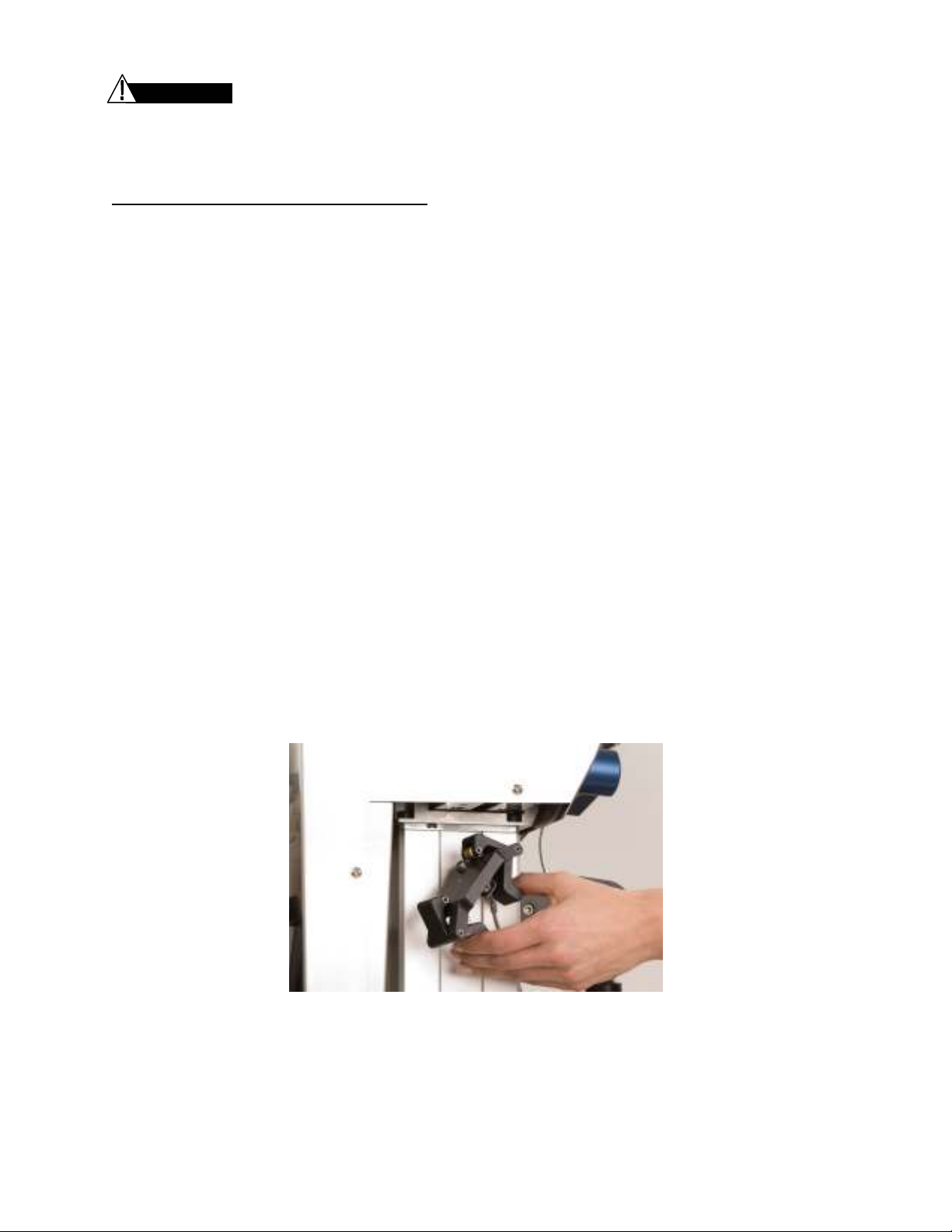
Installing the Head Lock-Out Clamp
When mounting the Axis Jackson System, the Head-End Lock-out Clamp (P/N 6977-
830) is required to be installed. The clamp prevents the sliding movement of the Head-
End Column of the 5803 Base which is allowed when other modular tops are utilized.
1. Verify that the 4 caster locks on the 5803 Advanced Control Base are locked in
position.
2. Standing at the Head-End of the base, pull the top of the Head-End Column toward
you and away from the center of the base.
3. Align the pins on the top of the Clamp (P/N 6977-830) with the holes under the top of
the Head-End Column. The label on the top of the clamp should be facing outward.
4. Pinch the clamp lever-arms and allow the jaws of the Clamp to grab the underside of
the Head-End Column. When properly positioned, release the clamp lever arms and
the clamp will seat itself. The red label should not be visible.
5. Confirm the Clamp is installed correctly:
a) Pull on the lanyard with moderate force (5-10 lbs/2.5 – 5 kg) – the Clamp should
remain in place.
b) Attempt to move the Head-End Column forward and backward - no motion
should be detected.
If the red label is visible, the Clamp did not remain in place, and/or motion in the
Head-End Column is detected, remove the Clamp and re-install following steps 1-5.
Figure 6: Installing the Head-End Lock-out Clamp
MIZUHOSI 2009 17 NW0507 Rev G
Page 18

WARNING
WARNING
WARNING
Installing the Foot-End Support Assembly
IMPORTANT: The Foot-End Column Slider must be installed prior to installing the
Foot-End Support Assembly.
To install the Foot-End Support Assembly, two people working together should
complete the following steps:
1. Lift the Foot-End Support Assembly and place it onto the table base.
2. Lift and align the catch with the dowel pins on the Foot-End Crossbar and install a T
Pin (P/N 5840-361) to secure it in place.
3. To attach the Foot-End Support Assembly to the Foot-End Column Slider, slide the
catch mechanism to engage the pin on the back side of the assembly. An audible
“click” confirms the latch mechanism is secured in place.
T-pin (drop lock end)
T-pin (handle end)
T-pin (handle end)
Figure 7: Installing the Foot-End Support Assembly
Verify that the T-pin is inserted and passes completely through the
Foot-End Support Assembly and Crossbar. Verify the T-pin drop lock is
in sight and pivots freely (see Figure 7 illustration). Failure to do so
may result in the patient and table assembly being dropped and may
result in serious injury to the patient and others.
T-pin (drop lock end)
Failure to follow the prescribed procedures for securing the Foot-End
Support Assembly to the Crossbar, may result in the patient and table
assembly being dropped and may result in serious injury to the patient
and others.
Axis Jackson
®
System Hinged Frame Installation Cart
Mounting the Hinged Frame on the 5803 Advanced Control Base for Use
The Installation Cart is not intended for patient transport.
MIZUHOSI 2009 18 NW0507 Rev G
Page 19

CAUTION
CAUTION
Caster Guard, Foot End
5803 Center Beam
WARNING
The Hinged Frame should not be utilized for patient positioning when in
place on the Installation Cart.
Avoid using this product in a manner not specified by Mizuho OSI.
IMPORTANT: It is recommended that two people work together when using the
Installation Cart with the Hinged Frame.
Always keep body parts, hands, fingers, etc. clear of moving parts and
pinch points when completing this procedure.
5803 Base Preparation:
Prior to mounting the Hinged Frame on the 5803 Advanced Control Base, complete the
steps outlined previously in this manual to prepare the base. i.e. install the Column
Sliders, Head-End Support and Foot-End Support Assemblies.
Lock the (4) caster locks of the Advanced Control Base.
Move columns of the base to maximum height up:
•
On the 5803 Hand Pendant depress and hold the Height Up button until the columns
of the Base travel to full extent of travel.
Installation Cart Positioning:
Maneuver the Installation Cart (Cart) next to and parallel to the 5803 base (Base) by
placing it into a position between the columns on the Rotation Lock (blue handle) side of
the Head-End column.
•
Cart labels Head-End and Foot-End should align with the orientation of the columns.
•
Cart should remain parallel to the Base as it is rolled into position.
•
Roll the Cart into its final position: the Bumper on the Foot-End of the Cart must be
in contact with the Foot-End of the Base and the two caster guards in contact the
5803’s center beam as shown. Note the Head-End bumper, not shown, does not
contact the base.
Foot End Bumper
Lock the (2) caster locks of the Installation Cart.
MIZUHOSI 2009 19 NW0507 Rev G
Page 20

Clearance 1
Clearance 2
Foot-End Head
-
End
Prior to moving the Cart Slider into position between the columns of the Base ensure the
Hinged Frame is centered (has clearance) between the Foot and Head-End Support
Assemblies.
Foot End
Frame Bracket
Clearance 1 can be easily adjusted by sliding the Hinged Frame toward the Foot-End.
Note increasing clearance 1 causes the Foot-End Frame Bracket to become more vertical.
Move to the opposite side of the base, locate and lift the Release Handle of the Installation
Cart and pull the Cart Slider towards you until it reaches its full extent of travel.
The Cart Slider should lock in place when the Release Handle returns to its neutral
position.
IMPORTANT: THE HINGED FRAME FOOT-END IS ALWAYS “FIRST ON, LAST OFF”.
Hinged Frame Foot-End Installation Preparation:
Rotate the dovetail plate to a level position as shown.
Center the Hinged Frame to the dovetail plate as shown. (If necessary, slide the
Hinged Frame laterally or toward the Head-End or Foot-End as needed to center the
frame between the Head-End and Foot-End Support Assemblies. There is some lateral
free play in the Cart Slider to assist in centering.
Pivot Block
Dovetail
Plate and
Frame
Centered
and Frame
NOT Aligned
MIZUHOSI 2009 20 NW0507 Rev G
Page 21

Frame
Clearance 3
CAUTION
Adjust frame until the Foot-End Bracket has sufficient clearance to mate with the
dovetail plate as shown. (Typically, when the Foot-End Bracket just touches the FootEnd of the Hinged Frame at the angle shown.)
Foot-End Frame
Foot-End
Bracket
pocket for
dovetail plate
engagement
Foot-End
Bracket in
contact with
Foot-End
Always keep body parts, hands, fingers, etc. clear of moving parts and
pinch points when completing this procedure.
Install the Hinged Frame onto the Foot-End Support Assembly:
Utilizing the 5803 Hand Pendant:
•
Use a second person to observe the Foot-End of the Hinged Frame, ensuring there
is adequate clearance for the moving parts.
o
If there is an interference between parts, return the column to its full height up
position. After motion has stopped adjust the Hinged Frame and dovetail plate
as needed to obtain adequate clearance. It may be necessary to slide the frame
toward the Head-End Column in order to angle the Foot-End Bracket away from
the Foot-End Support Assembly.
•
Depress and hold the Reverse-Trendelenburg button, to lower the Foot-End Column
until dovetail plate is aligned with pocket in the Foot-End Bracket.
MIZUHOSI 2009 21 NW0507 Rev G
Page 22
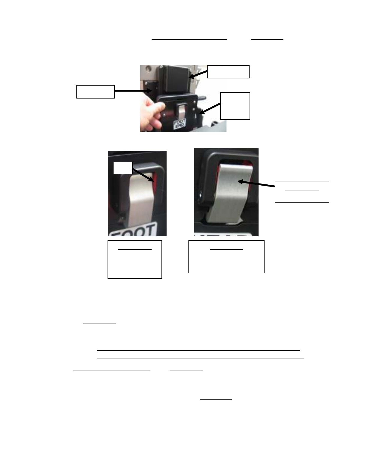
VISIBLE
• Adjust the dovetail plate using Reverse Trendelenburg and/or Height Up buttons
until the top of the Foot-End Bracket is just below the shield cover.
Shield Cover
Clearance
Foot-
End
Bracket
Red
Frame Latch
(silver button)
Frame Latch
DISENGAGED
POSITION
NOTE-
Frame Latch
ENGAGED POSITION
NOTE- RED COLOR IS
COVERED BY LATCH
• Press the Foot-End Bracket against the dovetail plate until the Latch is FULLY
DISENGAGED, as shown above.
• Depress Height Up so the dovetail plate of the Foot-End Support Assembly latches
into the Foot-End Bracket of the Hinged Frame.
IMPORTANT: if the Foot-End of the Frame begins to lift off the Cart Slider
before the Frame Latch is FULLY ENGAGED, STOP MOTION.
Use the Reverse Trendelenburg and Height Up buttons to adjust the dovetail plate
height, realign the frame to the pivot block and repeat the process indicated above.
• When the Latch is fully engaged the Foot-End of the Hinged Frame can be raised off
the Cart Slider by depressing and holding the Height Up button
•
Depress the Height Up button to raise the Foot-End Column to its full extent of
travel.
MIZUHOSI 2009 22 NW0507 Rev G
Page 23
Install the Hinged Frame onto the Head End Support Assembly:
Rotate the Head-End Bracket of the hinged frame toward the hinge.
Utilizing the 5803 Hand Pendant:
• Lower the Head-End dovetail plate by depressing and holding the Trendelenburg
button until it is approximately 2.5 “(6cm) above the Head-End Bracket.
• Raise the Head-End Bracket to engage the dovetail plate and press the Head-End
Bracket against the dovetail plate until the Latch is FULLY DISENGAGED, as shown
below. (See above for description of fully disengaged Latch.) If the Latch is not fully
disengaged, then use Trendelenburg or Height Up buttons to readjust the dovetail
plate height until the Latch is fully disengaged. It may be necessary to slide the
Head-End of the frame laterally toward the Foot-End in order to align the Head-End
Bracket with the dovetail plate.
Head-
End
Bracket
Red
• When properly aligned depress Height Up button so the dovetail plate of the HeadEnd Support Assembly latches into the Head-End Bracket of the Hinged Frame. The
Head-End of the Hinged Frame can now be raised off the Cart Slider by depressing
the Height Up button.
IMPORTANT: If the Head-End of the frame begins to lift off the Cart Slider
before the Frame Latch is FULLY ENGAGED, STOP MOTION.
MIZUHOSI 2009 23 NW0507 Rev G
Page 24

Use the Trendelenburg and Height Up buttons to adjust the dovetail plate height, realign
the frame to the pivot block and repeat the process indicated above.
• Depress and hold the Height Up button raising the Foot-End Column to its full extent
of travel.
The Hinged Frame should now be fully supported by the Head-End and Foot-End Columns
of the base and positioned at its maximum height with the Head-End and Foot-End Latches
fully engaged.
Remove Installation Cart:
Prior to retracting the Cart Slider, be sure there is clearance between the Cart Slider and
the hinged frame.
• Lift the Release Handle of the Installation Cart and push the Cart Slider over into its
stored position.
• An audible click will be heard confirming the Cart Slider is locked in the stored
position. Manually test the Cart Slider top to ensure it is securely locked into
position at both ends of the cart.
• Unlock the (2) caster locks of the Installation Cart and move away from the base.
Continue the installation procedure by following the steps in “Connecting the Axis
Jackson ® Controller and the Hinged Frame”
MIZUHOSI 2009 24 NW0507 Rev G
Page 25

CAUTION
CAUTION
WARNING
WARNING
Removing the Hinged Frame from the 5803 Advanced Control Base for Storage
The Installation Cart is not intended for patient transport.
The Hinged Frame should not be utilized for patient positioning when in
place on the Installation Cart.
Avoid using this product in a manner not specified by Mizuho OSI.
IMPORTANT: It is recommended that two people work together when using the
Installation Cart with the Hinged Frame
Always keep body parts, hands, fingers, etc. clear of moving parts and
pinch points when completing this procedure.
Lock the (4) caster locks of the 5803 Advanced Control Base.
Ensure all components have been removed from the Hinged Frame and are stored on
the Component Cart prior to removing the Hinged Frame.
Confirm the Hinged Frame is in the neutral “HOME” position by checking the 6977
Hand Pendant, the display should read +00 and the 3 LED’s should be lit. If necessary,
utilize the Hand Pendant “Return to Home” button to return the Hinged Frame to the
neutral “HOME” position and the display reads +00.
Raise frame: (to maximum height by utilizing the 5803 Hand Pendant)
• Depress and hold the Height Up button until the columns of the base travel to full
extent of travel.
Remove Cables:
• Disconnect the Blue, White and Brown cables from the Hinged Frame, Controller,
Head-End Support Assembly and Foot-End Support Assembly. Place in the storage
area on the Installation Cart.
Installation Cart Positioning:
Maneuver the Installation Cart (Cart) next to and parallel to the 5803 base (Base) by
placing it into a position between the columns on the Rotation Lock (blue handle) side of
the Head-End column.
• Cart labels Head-End and Foot-End should align with the orientation of the columns.
• Cart should remain parallel to the Base as it is rolled into position.
• Roll the Cart into its final position: the Bumper on the Foot-End of the Cart must be
in contact with the Foot-End of the Base and the two caster guards in contact the
5803’s center beam as shown. Note the Head-End bumper, not shown, does not
contact the base.
MIZUHOSI 2009 25 NW0507 Rev G
Page 26

Caster Guard, Foot End
5803 Center Beam
Foot End Bumper
Lock the (2) caster locks of the Installation Cart.
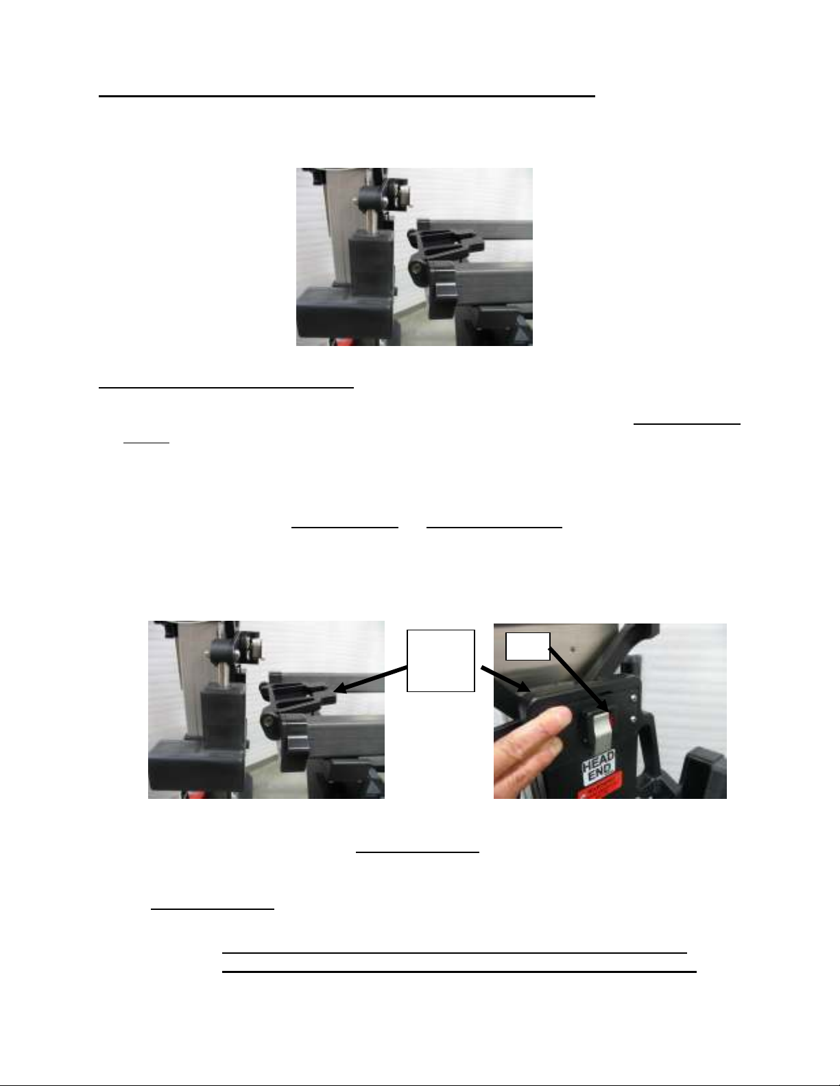
Remove the Hinged Frame from the Head-End Support Assembly:
Utilizing the 5803 Hand Pendant:
Depress and hold the Trendelenburg button, simultaneously a second person should
depress the silver button on the Head-End Bracket of the frame. These actions will
result in lowering the Head-End Column of the base and allowing the Head-End of the
Hinged Frame to be released from the Head-End Support Assembly and rest on the
Cart Slider.
Hold the Head-End Bracket of the Hinged Frame away from the dovetail support of the
Head-End Support Assembly, simultaneously depress and hold the Height Up button
raising the Head-End Column to its extent of travel.
Remove the Hinged Frame from the Foot-End Support Assembly:
Utilizing the 5803 Hand Pendant:
Depress and hold the Reverse Trendelenburg button, simultaneously a second person
should depress the silver button on the Foot-End Bracket of the frame. These actions
will result in lowering the Foot-End Column of the base and allowing the Foot-End of the
Hinged Frame to be released and rest on the Cart Slider.
Hold the Foot-End Bracket of the Hinged Frame away from the dovetail plate support of
the Foot-End Support Assembly, simultaneously depress and hold the Height Up
button raising the Foot-End Column to its extent of travel.
The Hinged Frame should now be fully supported on the Cart Slider of the Installation
Cart.
MIZUHOSI 2009 26 NW0507 Rev G
Page 27

Remove Installation Cart:
Prior to retracting the Cart Slider, be sure there is clearance between the Cart Slider and
the hinged frame.
• Locate and lift the Release Handle of the Installation Cart and push the Cart Slider
with Hinged Frame over into its stored position.
• An audible click will be heard confirming the Cart Slider is locked in the stored
position. Manually test the Cart Slider top to ensure it is securely locked into
position at both ends of the cart.
• Unlock the (2) caster locks of the Installation Cart and move away from the base.
Remove Components from Base:
Remove the Axis Jackson Controller, Foot-End Support Assembly, Head-End Support
Assembly and Column Sliders and store in the appropriate area on the cart.
Cover Installation Cart:
Cover the Installation Cart with the dust cover provided and move to the storage
location.
MIZUHOSI 2009 27 NW0507 Rev G
Page 28

Connecting the Axis Jackson Controller and the Hinged Frame
Serial Number
Tag
Brown Cable
ACP Tubing Port
(Unused)
Blue Cable
Controller On/Off
Switch
White Cable
Controller Power
Cord Receptacle
Figure 8a and 8b: Controller Cable Connections
To connect the Controller:
1. Mount the Axis Jackson Controller on the Foot-End Column by sliding the handle
over the top of the Column crossbar.
2. Secure by inserting a T-pin through the mounting handle and crossbar.
3. Prior to connecting the Controller: run the Cable (P/N 6977-4110, color coded white)
under the Foot-End Column between the wheels. Wrap the Cable around the I-beam
of the base and secure with attached Velcro™ straps. The Cable should be secured
to the beam so it does not contact the floor if the base needs to be moved. Connect
the Head-End Frame Support Assembly 90 degree end of the Cable to the HeadEnd Support Assembly and the other end of the Cable color coded white to the
corresponding white labeled port on the Controller.
4. Connect the Foot-Elevator Cable (P/N 6977-4140, color coded brown) to the FootEnd Support Assembly and the corresponding color coded brown labeled port on the
Controller.
5. Connect the Hinged Frame Cable (P/N 6977-4130, color coded blue) to the Hinged
Frame and the corresponding color coded blue labeled port on the Controller.
6. Connect the Axis Jackson Controller power cord to the Controller and to an electrical
outlet.
MIZUHOSI 2009 28 NW0507 Rev G
Page 29

CAUTION
An external ground stud is required for use when the AC
power cable is not connected to a protective earth ground outlet in
your operating room or facility. To protect the patient and hospital
staff from any possible hazards, an external ground wire connection
is required between the external ground stud and protective earth
ground. Failure to comply with this requirement may result in
damage to the product, and injury or death of personnel.
7. If the electrical outlet being utilized is not grounded, connect the external ground
stud to a protective earth ground.
Hand Pendant with Junction Box (P/N 6807-5)
1. To connect the Axis Jackson Hand Pendant, plug the long cable extending from the
Junction Box on the Hand Pendant into the port on the Head-End Support
Assembly.
2. Connect the short lead from the Junction Box to the 5803 Head-End Column Hand
Pendant port.
3. Connect the 5803 Hand Pendant to the remaining receptacle on the Junction Box.
5803 Base Hand Pendant and 6977 Axis Jackson System Hand Pendant
When the Axis Jackson System is utilized it requires the use of both the 5803 Advanced
Control Base Hand Pendant and the 6977 Axis Jackson Hand Pendant. The two Hand
Pendants are intended to be placed in the Holster (P/N 6977-4162) provided with the
Axis System for easy access and simultaneous use. The 5803 Hand Pendant controls
table top height adjustment, Trendelenburg and Reverse Trendelenburg positions. The
6977 Hand Pendant controls the Hinged Frame movement, Foot Elevator and Lateral
Roll.
MIZUHOSI 2009 29 NW0507 Rev G
Page 30

Figure 9: The 6977 Axis Jackson Hand Pendant and 5803 Advanced Control Hand Pendant
(Shown mounted in Holster)
Hinge Angle Digital
Display
Hinge Up
V Hinge Up
Foot Elevator
Down
Hinge Down
V Hinge Down
Foot Elevator
Up
Left Lateral
Roll
Right Lateral
Roll
Return To Home
Memory Position 1
& 2
Memory Store
Indicator Lights
(3 places)
Figure 10: The Axis Jackson Hand Pendant
MIZUHOSI 2009 30 NW0507 Rev G
Page 31

Axis Jackson Hand Pendant Operation
To control the angle of the Hinge and transition from a neutral or 00° position up to +35°
Hinge up or -20° Hinge down, depress the appropriate button on the Hand Pendant.
The selected function will continue to operate until the button is released or the Hinged
Frame has reached the extent of its travel. The angle of the Hinge is displayed on the
digital display. The readout will display +00 when the Hinge is in the neutral position and
the table top is level.
To raise the Hinge and lower the Foot-End of the table top simultaneously, depress the
Hinge Up button (on the left side of the control with the arrows that point up in the
middle and down at the foot).
To lower the Hinge, depress the Hinge Down button (on the right side of the control with
the arrows that point down in the middle and up at the foot).
To raise the Hinge only without lowering the Foot-End of the table top, depress the V
Hinge Up button (on the left side of the control, with the arrow that points up in the
middle).
To lower the Hinge only, depress the V Hinge Down button (on the right side of the
control with the arrow that points down in the middle).
To lower the Foot-End of the table top, depress the Foot Elevator Down button (on the
left side of the control, with the arrow that points down at the foot).
To raise the Foot-End of the table top depress the Foot Elevator Up button (on the right
side of the control with the arrow that points up at the foot). The Foot Elevator can only
be raised if lower than the neutral or starting position.
To Lateral Roll the table top to the left, depress the Left Lateral Roll button (on the left
side of the control).
To Lateral Roll the table top to the right, depress the Right Lateral Roll button (on the
right side of the control).
Hinge Position Memory
A Hinge angle position can be stored in memory for ease of returning to the desired
position. To save a position in memory, transition the Hinged Frame to the desired
position, depress and hold the Memory Store (MEM STORE) button; then depress one
of the numbered memory buttons. Continue to depress both buttons until the Indicator
Lights on the hand pendant flash, confirming the position is stored in memory.
To transition the frame to a stored position, depress and hold the pre-programmed
Memory 1 or Memory 2 button. The table top will transition to the position in memory.
To re-program the position stored as Memory 1 or Memory 2, repeat the above
programming process.
NOTE: Lateral Roll, Height, Trendelenburg and Rev Trendelenberg positions can not be
saved to Memory 1 or Memory 2.
MIZUHOSI 2009 31 NW0507 Rev G
Page 32

Hinge Angle Digital Display
The Axis Jackson Hand Pendant displays the position of the Hinge of the frame.
• When the Hinge of the frame is neutral, the table top level, the Hinge angle
displayed is 00°.
• When the Hinge is raised, the Hinge angle displayed is +1° to +35°.
• When the Hinge is lowered, the Hinge angle displayed is -1° to -20°.
Should the Hinge angle display read 106 or 107, the Hinged Frame needs recalibration.
Axis Jackson Hinged Frame Calibration Procedure
1. On the Axis Jackson Controller, toggle the main Power Switch to OFF and then to ON.
2. The Hand Pendant will display a number. Once the number is displayed,
immediately (within 20 seconds) press and release the Mem Store and Hinge Up
buttons simultaneously (the top left and bottom left buttons) once. The system will
enter calibration mode and the Hand Pendant display will begin flashing +35.
3. Using the Hand Pendant, press the V Hinge Up button until the Hinge is raised to its
extent of travel and stops.
4. Simultaneously press and release the Mem Store and Hinge Up buttons once. The
Hand Pendant display will begin flashing +00.
5. Using the Hand Pendant, press the V Hinge Down button until the Hinge lowers to
its neutral or level Hinge position.
6. Simultaneously press and release the Mem Store and Hinge Up buttons once. The
Hand Pendant display will begin flashing -20.
7. Using the Hand Pendant, press the V Hinge Down button until the Hinge lowers from
neutral position to its extent of travel and stops.
8. Simultaneously press and release the Mem Store and Hinge Up buttons once. The
Hand Pendant will briefly display +77 to indicate that the calibration was completed
successfully. Following the display +77, the Hand Pendant will return to normal use
mode and display -20.
9. If the calibration process was unsuccessful, the Hand Pendant will display a blinking
error code either 106 or 107.
Repeat Steps 1-8 to re-calibrate. If re-calibration is unsuccessful a second time, contact
Technical Service.
LED Indicators
The Axis Jackson Hand Pendant has three Indicator Lights located between the Foot
Elevator, Hinge and Lateral Roll buttons.
Foot Elevator Indicator is illuminated when the foot elevator has returned to its home
position, level with the Hinge.
Hinge Indicator is illuminated when the Hinge has returned to its neutral, 00° position.
Lateral Roll Indicator is illuminated when the table top is level side to side.
MIZUHOSI 2009 32 NW0507 Rev G
Page 33

5803 Hand Pendant Operation (see 5803 Owner’s Manual for detailed instructions)
Press a button on 5803 Hand Pendant to adjust the table top. The selected function will
continue to operate until the button is released or the extent of travel of the Columns is
reached.
To raise the table, depress the Height Up button, both Columns raise simultaneously to
raise the height of the table top
To lower the table, depress the Height Down button, both Columns lower
simultaneously to lower the height of the table top.
To move the table top into a Trendelenburg position, depress the Trendelenburg button
until the desired angle is reached. This function lowers the Head-End Column of the
base and raises the Foot-End Column base simultaneously.
To move the table top into a reverse Trendelenburg position, depress the Reverse
Trendelenburg button until the desired angle is achieved. This function raises the HeadEnd Column and lowers the Foot-End Column of the base simultaneously.
Note: The Lateral Roll/Tilt buttons on the 5803 Hand Pendant are inoperable when
the Axis Jackson System is installed. Lateral Roll is provided and controlled
through the 6977 Axis Jackson System Hand Pendant.
MIZUHOSI 2009 33 NW0507 Rev G
Page 34

5.0 PRE-OPERATION FUNCTION CHECKS
Checking the Advanced Control Base
Perform all the steps in this procedure to verify correct base operation.
Ensure the 5803 Hand Pendant cable is securely plugged into the 6977 Hand
Pendant Junction Box.
Ensure the base power cord is connected to a hospital grade power outlet and
toggle the main on/off power switch to ON. Verify the switch illuminates; this
indicates power is applied to the modular base.
Verify the Hand Pendant battery status indicator is lit, and fault indicator is not lit.
Press and hold the Hand Pendant Height Up button. Verify the table moves up.
Press and hold the Hand Pendant Height Down button. Verify the table moves
down.
Press and hold the Hand Pendant Trendelenburg button. Verify the table moves
into a Trendelenburg position.
Press and hold the Hand Pendant Reverse Trendelenburg button. Verify the table
moves into a reverse Trendelenburg position.
The Tilt/Roll function of the base is Locked Out when the Axis Jackson Controller
is installed. The Tilt status indicator on the Head-End Column should remain
illuminated
Checking the Axis Jackson Hinged Frame
Perform all the steps in this procedure to verify correct Axis Jackson operation.
Confirm the Axis Jackson Hand Pendant cable is inserted into the port located on the
side of the Head-End Frame Support Assembly.
Confirm the Axis Jackson Controller power cord is plugged into a hospital grade
power outlet and the ON/OFF power switch is toggled to the ON position. Verify
the switch illuminates; this indicates power is applied to the table top.
Depress and hold the Axis Jackson Hand Pendant Hinge Up button. Verify the
Hinge of the frame moves up and the Foot-End of the frame moves down.
Continue to depress the Hinge Up button until motion stops. Verify the Hinge angle
displayed on the Hand Pendant is +35° (±2°).
Depress and hold the Hand Pendant Hinge Down button. Verify the Hinge of the
frame moves down.
Continue to depress the Hinge Down button until motion stops. Verify the Hinge
angle displayed on the Hand Pendant is -20° (±2°).
Press and hold the Hand Pendant V Hinge Up button. Verify the Hinge of the frame
moves up.
Continue to depress the V Hinge Up button until motion stops. Verify the Hinge
angle displayed on the Hand Pendant is +35° (±2°).
MIZUHOSI 2009 34 NW0507 Rev G
Page 35

Press and hold the Hand Pendant V Hinge Down button. Verify the Hinge of the
frame moves down.
Continue to depress the V Hinge Down button until motion stops. Verify the Hinge
angle displayed on the Hand Pendant is -20° (±2°).
Press and hold the Hand Pendant Foot Elevator Down button. Verify the Foot-End
of the frame moves down.
Press and hold the Hand Pendant Foot Elevator Up button. Verify the Foot-End of
the frame moves up.
Note: The Foot-End of the frame moves up unless it is at the neutral (level) position.
Press and hold the Hand Pendant Lateral Roll Left button. Verify the Hinge frame
rolls to the left when standing at the Head-End of the frame and facing the FootEnd Column.
Press and hold the Hand Pendant Lateral Roll Right button. Verify the Hinge frame
rolls to the right when standing at the Head-End of the frame and facing the FootEnd Column.
Move the Hinge Up or Hinge Down and translate the frame to Lateral Roll Right or
Left. Now, press and hold the Hand Pendant ‘Return To Home button’. Verify the
Hinged Frame rolls back to level and then returns the Hinge to the neutral position.
Verify the Hinge angle displayed on the Hand Pendant is 00°. All three LEDs
corresponding to the Hinge, Foot Elevator and Lateral Roll should all be
illuminated when the frame is in the neutral position.
Toggle the ON/OFF switch for the Advance Control Pad System to the ON position
Verify that air comes out of the tubing connector port on the Controller.
Press the Cycle Selection button on the ACP Control Panel and confirm the cycles
change accordingly.
Press the red E-Stop button in. An audible beep should be heard. The red LED
should flash. To reset, turn the red button in the direction of the arrows to reset.
MIZUHOSI 2009 35 NW0507 Rev G
Page 36

6.0 OPERATING THE SYSTEM
Axis Jackson Controller:
Power On/Off
Serial Number
Tag
Brown Cable
Controller On/Off
Switch
Controller Power
Cord Receptacle
Figure 11: Controller ON/OFF Switch
The Axis Jackson Controller (P/N 6977-4006, 120V or 6977-4005I, 230V) has a power
ON/OFF switch. This switch also serves as a circuit breaker and in the event of an
overload condition the switch will trip. To reset the circuit breaker, toggle the switch to
the OFF position and then to the ON position.
IMPORTANT: Determine and correct the source of the overload prior to resetting this
switch.
MIZUHOSI 2009 36 NW0507 Rev G
Page 37

Emergency Stop (E-Stop) and Reset
To immediately interrupt the power to the Axis Jackson System, press the Emergency
Stop Button. An audible beep will be heard from the Controller and the red LED will
illuminate and flash to indicate that the power has been interrupted
To reset the system, turn the Emergency Stop Button in the direction of the arrows until
it returns to the original position.
Figure 12: Axis Jackson Controller Emergency Stop
Advance Control Pad System
Figure 13: ACP Control Panel
The Axis Jackson System includes the Advance Control Pad System (ACP) with
Tempur-med®. Tempur-med® Axis Jackson ACP Pads provided are:
(1) Left Contoured, ACP Combination Hip and Thigh Pad (P/N 6977-710)
(1) Right Contoured, ACP Combination Hip and Thigh Pad (P/N 6977-720)
(1) Bilateral Winged ACP Chest Pad (P/N 6977-700)
MIZUHOSI 2009 37 NW0507 Rev G
Page 38

The pads are designed specifically with Tempur-med® material for use with the Axis
Jackson Hinged Frame and Controller. Air cells within the pads inflate and deflate with
varying degrees of frequency and duration providing massage action and periodic
pressure point stimulation to the patient’s chest, hips and thighs.
At the discretion of the physician, the pads can be used for patient support on the Axis
Jackson Hinged Frame without the massage action being activated.
The Axis Jackson Controller must be turned on at its main power switch in order to use
the built-in Advance Control Pad System. The ACP Control Panel is located on the front
of the Controller. Turn on the ACP System by toggling the On/Off switch to the ON
position. The ACP panel LEDs will light up and air flow can be felt at the tubing
connection port at the back of the Controller.
ACP Tubing Port
(Unused)
Blue Cable
White Cable
1.0 Figure 14: Port to Connect ACP Tubing
Prior to patient use, the ACP Quick Connect Tubing needs to be connected to the pads
and the Controller.
After the Chest Pad and Hip/Thigh Pad are in place on the frame, the tubing can be
connected to the pads. Align the tubing with the long end directed to the pad furthest
away from the Controller port.
Secure the ACP tubing with the Velcro™ and the clips along the frame. Ensure the
tubing is secure and out of the way such that the tubing will be able to move when the
Hinged Frame is moved. Utilize the Hand Pendant and move the Hinge Up and Hinge
Down to the extent of its travel. Re-adjust the ACP tubing as may be required.
IMPORTANT: Verify the ACP tubing will not be stretched or pinched during hinge
movement which may interrupt or obstruct air flow to the pads. Failure
to do so may result in ACP malfunction.
MIZUHOSI 2009 38 NW0507 Rev G
Page 39

Cycles at 5 sec intervals
CAUTION
Cycle Selector and Cycle Indicator
The ACP Control Panel graphically illustrates 4 pre-programmed cycles. The graphic
shown in Figure 15 illustrates the frequency and duration of the air cells movement.
Choice of cycles is at the discretion of the user and whether or not more or less frequent
massage is preferred.
Cycles at 10 sec intervals
Cycles at 60 sec intervals
Cycles at 5 sec intervals
for 25 sec, rest for 30 sec
1.1.1 Figure 15: ACP Control Panel Cycle Selector and Cycle Indicator
Pressing the Cycle Selector Button changes the frequency at which the cells in the pads
inflate and deflate. Pressing the Button once moves the selected mode from 1 to 2,
once more from 2 to 3, next 3 to 4, the next press changes the cycle from 4 to 1.
Cycle Indicators (2) are located on the ACP Control Panel. The Cycle Indicators
provide visual confirmation that ACP system is alternating cycles.
Note: The Advance Control Pad System is not utilized with the Supine Tops and one
piece table pad and the ACP control switch can remain in the OFF position.
However the ON/OFF switch to the Controller needs to remain in the ON
position at any time the Hip/Thigh and Chest Pad will be utilized for prone
positioning.
Axis Jackson System Manual Operation
In the event of a power failure, the Hinge and the Foot Elevator may be operated
manually to return the Hinged Frame to a level position to facilitate patient transfer.
To manually operate the Hinge:
1. Turn the power off at the Controller and unplug the AC power cord. Disconnect
Cable, color coded blue, to Hinged Frame.
Failing to turn off the power and unplug the cord may cause a potential
safety hazard that may result in injury to the operator.
MIZUHOSI 2009 39 NW0507 Rev G
Page 40

2. Use the Gearbox Crank Handle (P/N 6977-886) which is stored on the side of the
Foot Elevator.
3. Remove the 1.25” (3.2 cm) Black Cover Plug (P/N NB0339) and the 3/4” (1.9 cm)
Black Cover Plug (P/N NB0363) from either the right or left side of the Foot-End of
the Hinged Frame and insert the Gearbox with Crank Handle into the socket.
4. Turn the Gearbox Crank Handle to raise the Hinge to the level position or to lower
the Hinge to a level position.
5. Return the Gearbox Crank Handle to the storage location on the side of the Foot
Elevator.
6. Recap the openings on the side of the Foot-End of the Hinged Frame with the Black
Cover Plugs.
To manually operate the Foot Elevator:
1. Turn the power off at the Controller and unplug the AC power cord.
2. Use the Crank Handle (P/N 6977-679) which is stored on the back of the Controller.
3. Remove the 1” (2.5 cm) Black Cover Plug (P/N NB0360) on top of the Foot Elevator
and insert the Crank Handle into the socket to begin manual operation.
4. Turn the Crank Handle clockwise to raise the Foot-End of the Hinged Frame back to
a level position.
5. Return the Crank Handle to the storage location on the back of the Controller. Clip
into place.
6. Recap the opening on the top of the Foot Elevator with the Black Cover Plug.
MIZUHOSI 2009 40 NW0507 Rev G
Page 41

Advanced
Control Pad System™ (ACP)
Hinged Fram
e
Contoured
Bilateral Winged
Torso Trolley™
5-Way Adjustable Arm
7.0 PRONE POSITIONING
Prone Set-up On Hinged Frame
stimulates patient pressure points on chest, hips and thighs
– automatically
Chest Pad
- integrates
patient movement with hinge
translation
Boards
Carbon Fiber Frame Construction
– supports spine
biomechanics and improves
surgeon access
Removable Foot Board
Hip/Thigh Pads
Adjustable Leg Sling
Hinged Frame
Figure 16: Axis Jackson for Prone Procedures
The Axis Jackson System can be set-up for prone patient positioning according to the
following procedure:
Move the table to the desired location and lock the base by engaging the (4) caster
locks
Confirm that the Axis Jackson Hinged Frame is correctly mounted on the base and the
Controller is plugged in and turned on. The Axis Jackson Hand Pendant will illuminate
displaying the current Hinge angle. It should read 00°. If it does not, confirm the Hand
Pendant is connected, power to the frame is turned on and depress Return to Home
Confirm that the 5803 modular base is plugged in and turned on. The 5803 Hand
Pendant indicator lights will be illuminated as well as the Head-End Column indicator
lights for the Rotation Safety Lock, the Rotation Lock and the Tilt Drive Status will be
illuminated.
MIZUHOSI 2009 41 NW0507 Rev G
Page 42

WARNING
Torso Trolley®
The Torso Trolley® consists of a Chest Slide (P/N 6977-503) to which the Bilateral
Winged ACP Chest Pad and 5 way Adjustable Armboards are mounted. To install the
Chest Slide on the Hinged Frame, first ensure the Hinged Frame is in the neutral
position, Hinge angle 00° and table level side to side.
Linkage Bar
Figure 17: Rail Assembly
Lock/Unlock
1. Slide the Right Rail Assembly (P/N 6977-501) and Left Rail Assembly (6977-502)
onto the corresponding torso section of the Hinged Frame and lock into position.
(Refer to pictures A-D).
A B
C D
Verify the Left and Right Rail Assemblies are locked in position to
eliminate unintended Torso Trolley® movement and the potential for
injury to the patient.
2. Connect the linkage bar of the Rail Assembly to the Hinge by removing the bar from
its storage position and securing the green end over the Hinge knob. (Refer to
pictures E-F).
E F
3. Position the Chest Slide over the brackets and place into position. The post of the
Rail Assembly will slip into position within the slide. After it is placed, you should
confirm operation by simultaneously depressing the green handles and pushing
outward. This releases the pins on the slide and should allow the Chest Slide to be
moved toward the head of the table and back toward the foot of the table. The 1-12
scale mounted on each Rail Assembly assists in identifying where the slide is in its
range of movement.
MIZUHOSI 2009 42 NW0507 Rev G
Page 43

Underside of
Chest Slide,
Insert Armboard
Mounting Bracket
Armboard Mounting
Bracket Inserted
Figure 18: Armboard Mounting Brackets
T-handle
4. Secure the Chest Slide by installing the Armboard Mounting Brackets (P/N 6977-
570). Insert the Armboard Mounting Brackets into the corresponding underside of
the Chest Slide and secure with the locking T-handle.
Figure 19: Torso Trolley® w/Bilateral Winged ACP Chest Pad
5. To attach the Bilateral Winged ACP Chest Pad (P/N 6977-700) to the Chest Slide,
slide the wings under the black tab (see Figure 20). The indentation for the suprasternal notch should be at the Head-End.
MIZUHOSI 2009 43 NW0507 Rev G
Page 44

Black Tab
Figure 20: Black Tab and Sliding Chest Pad in Place
6. The Bilateral Winged ACP Chest Pad is designed specifically for use with the Axis
Jackson System. Air cells within the center of the Tempur-med® pad inflate and
deflate with varying degrees of frequency and duration, providing massage action
and periodic pressure point stimulation to the patient’s chest. At the discretion of the
physician, the pad can be used for patient support without the pneumatic action.
Also at the discretion of the physician, additional foam or padding can be placed
between the patient and the sides of the pad as needed to accommodate varying
sizes and needs of patients.
7. Connect the tubing from the chest pad to the ACP Quick Connect Single Use
Tubing. Insert the white nipple on the disposable tubing into the black/gray port of
the tubing from the chest pad. To disconnect the tubing depress the gray portion of
the port and remove the white nipple.
8. Secure the ACP tubing with the Velcro™ and the clips along the frame. Ensure the
tubing is secure and out of the way such that the tubing will be able to move when
the Hinged Frame is moved. Utilize the Hand Pendant and move the Hinge Up and
Hinge Down to the extent of its travel. Re-adjust the ACP tubing as may be required.
IMPORTANT: Verify the ACP tubing will not be stretched or pinched during hinge
movement which may interrupt or obstruct air flow to the pads. Failure
to do so may result in ACP malfunction.
MIZUHOSI 2009 44 NW0507 Rev G
Page 45

5-Way Adjustable Armboards
The 5-way Adjustable Armboards (P/N 6977-980) are integral to the Torso Trolley®, and
when in place, move with the trolley when the Hinge is articulated.
Figure 21: 5-way Adjustable Armboard Mounting Bracket
Figure 22: Armboard Mounted on the Torso Trolley®
Mount the 5-way Adjustable Armboard unit by sliding the pivoting bracket into the
mounting bracket and securing the locking T handle. To adjust the Armboards, turn the
black knob until there is free movement of the pivoting arm, this allows for height
adjustment, lateral movement and pivoting of the Armboard. The Armboards can be
installed and pivoted out of the way for transfer of the patient on and off the frame.
When in place, the Armboards can also be translated toward the Head-End or Foot-End
depending on the positioning needs of the patient. To release the Armboard and allow
for translation towards the Head-End or Foot-End of the Hinged Frame, pull down on
the silver knob at the underside of the Armboard to release. Move into the desired
position and then return the silver knob to the locked position.
MIZUHOSI 2009 45 NW0507 Rev G
Page 46

Contoured Combination ACP Hip/Thigh Pads
Attach the Right and Left Contoured Combination ACP Hip/Thigh Pads (P/N 6977-720
and P/N 6977-710) at the Hinge.
The pads are designed to be right and left sided and are labeled accordingly. The pads
must be oriented to the patient when the patient is positioned prone on them. Confirm
the pads are applied to the appropriate side of the Hinged Frame. When properly
installed, the pads should slope down toward the Foot-End of the table and the green
latch will be on the outside of the frame.
Figure 23: Un-Latched Hip/thigh Pad on Hinged Frame
Figure 24: Left Hip/Thigh Pad Latched in Place at the Hinge with ACP Tubing Connected
To mount, hold the appropriate Hip/Thigh Pad with the green latch in the open position
over the Foot-End section of the frame. Place the inside of the pad bracket over the top
of the frame to engage the inside of the rail on the Hinge Cover. Slide the pad towards
the Hinge for the full length of the rail. It will come to a stop. Close the green latch
down on the rail. The pad should be secure on the rail in Position 1. Using both hands,
attempt to pull the pad toward the Foot-End of the frame - it should not move. If it is not
latched securely, remove the pad and repeat the process.
MIZUHOSI 2009 46 NW0507 Rev G
Page 47

WARNING
WARNING
IMPORTANT: The Hip/Thigh Pads are recommended to be latched in Position 1,
(closest to the Hinge) for the majority of patient heights less than 7 feet
(213 cm) tall. Moving the Hip/Thigh Pads to an alternate position (away
from the Hinge) should be done only at the discretion of the attending
physician.
Connect the tubing from the Hip/Thigh Pads to the ACP Quick Connect Single Use
Tubing. Insert the white nipple on the disposable tubing into the black/gray port at the
end the tubing from the Hip/Thigh Pads. To disconnect the tubing depress the gray
portion of the port and remove the white nipple.
Secure the ACP tubing with the clips along the frame. Ensure the
tubing is secured so that it is out of the way but will not be stretched or
pinched which may obstruct air flow.
Verify that the Hip/Thigh Pad green locking levers are latched securely
in place to eliminate unwanted Pad movement.
Leg Sling
Figure 25: Leg Sling (P/N 5840-450)
To install the adjustable Leg Sling (P/N 5840-450), place the sling over the trunk section
of the Hinged Frame. Feed the four straps through their respective buckles on the
opposite side of the sling and secure. The sling should be adjusted for each patient.
The straps on the sling consist of a double-sided hook closure that allows for infinite
adjustment along the length of the strap. The hook end of the strap may be folded over
onto the loop portion of the strap to allow for greater adjustability. The strap may be
folded over itself again to shorten, thereby raising the sling and decreasing the hip
flexion angle of the patient.
Place two (2) or three (3) pillows in the leg sling approximately where the patient’s lower
legs will rest to help achieve the desired amount of knee flexion and support.
MIZUHOSI 2009 47 NW0507 Rev G
Page 48

Foot Board
A removable Foot Board (P/N 6977-990) is provided for placement at the Foot-End of
the Hinged Frame. It allows for positioning pillows to be free of any contact with the
Foot-End Support Assembly.
Figure 26: Removable Foot Board
Retractor Adaptor for Axis Jackson Hinged Frame
The Retractor Adaptor (P/N 6977-939) mounts on the Hinged Frame and provides 6
inches (15 cm) of side rail for mounting retractors.
Patient Care Kits – GentleTouch and ProneView®
The GentleTouch and ProneView® Patient Care Kits may be used with the Axis
Jackson.
IMPORTANT: The choice of which Patient Care Kit best meets the positioning needs
of the patient is at the discretion of the attending physician.
GentleTouch Patient Care Kit
The GentleTouch Patient Care Kit (P/N/ 6980) includes a GentleTouch Face Pillow,
Chest Pad Cover, Hip/Thigh Pad Covers with Hinge Aprons and Foam Arm Cradles.
The components should be utilized as described in the Patient Care Kit instruction sheet
included in every kit.
ProneView® Patient Care Kit
®
The ProneView
Patient Care Kit (6980PV) includes a ProneView® Cushion Insert,
Chest Pad Cover, Hip/Thigh Pad Covers with Hinge Aprons and Foam Arm Cradles.
The components should be utilized as described in the Patient Care Kit instruction sheet
included in every kit.
MIZUHOSI 2009 48 NW0507 Rev G
Page 49

WARNING
The ProneView® Patient Care Kit works with the provided ProneView® Helmet and
Mirror System. The system is designed by the manufacturer to support the patient’s
head while in the prone position. Additionally, the position of the patient’s facial
alignment with the Helmet can be readily viewed while in the prone position.
The ProneView® Helmet and Mirror System includes:
1 reusable Adjustable Mirror Platform (P/N D28590CE)
1 reusable Helmet (P/N D28501CE)
1 single-use Cushion Insert (Cushion Inserts are provided in each Patient Kit)
Remove the ProneView® Helmet and Mirror System components from its packaging and
visually inspect the components for any damage. Do not use damaged goods.
IMPORTANT: Before installing and using the ProneView® Helmet and Mirror System
read all instructions and warnings in this Owner’s Manual and the
ProneView® Helmet and Mirror System instructions.
Note: The Adjustable Mirror Platform is a rectangular shaped device with a square
shaped mounting post pattern. The Adjustable Mirror Platform can be mounted
to the Chest Slide such that the ‘longer’ side of the platform can be oriented
either parallel or perpendicular to the overall length of the table. Mounting of
the Adjustable Mirror Platform with the longer side perpendicular to the overall
length of the table will provide the most available clearance between the
Helmet and the Head-End of the table.
Ensure that the Adjustable Mirror Platform Posts are in their lowest position by turning
the Posts clockwise until the base of the Adjustable Posts comes to rest on the
Adjustable Mirror Platform. This action will allow the Helmet Legs to easily engage the
Adjustable Mirror Platform Posts during patient transfer.
With the Adjustable Posts facing up, place the Adjustable Mirror Platform onto the Chest
Slide of the Axis Jackson. Figure 27 illustrates the Adjustable Mirror Platform mounted
to the Chest Slide. Figure 28 illustrates the ProneView® Mirror and Helmet System.
Verify there is adequate space between the Helmet and the Head End
Assembly to accommodate anticipated range of motion. The Axis
Jackson Chest Slide is designed to move simultaneously when the
Hinged Frame is translated to ‘Hinge-Up or Hinge-Down’. Failure to
verify may result in patient injury.
Refer to Section 9.0 Cleaning, Storage and Routine Maintenance for complete cleaning
instructions for the ProneView® Helmet and Mirror System.
IMPORTANT: Remove the ProneView® components from packaging and visually
inspect the components. The ProneView® Cushion Insert should be
opened 60 minutes prior to use and the arm cradles should be opened
20 minutes prior to use for complete expansion of the foam.
‘Fit’ the ProneView® Cushion Insert into the Helmet and within the tabs provided at the
chin end of the Helmet. Adjust the Cushion Insert openings to be centered relative to
the Helmet openings.
MIZUHOSI 2009 49 NW0507 Rev G
Page 50

WARNING
Head-End Assembly
Figure 27. ProneView® Adjustable Mirror Platform positioned on the Chest Slide
Adjustable Mirror
Platform and Chest
Slide (shown with the
longer side of platform
mounted perpendicular
to the overall length of
the table).
Figure 28: View of ProneView® Helmet and Mirror System positioned on the Chest Slide
Transferring the Patient
Prior to transferring the patient to the Axis Jackson table top, verify that
the Head-End and Foot-End Support Assemblies with Axis Jackson
Hinged Frame are properly installed on the 5803 Advance Control
Modular Base. Verify the T-pins pass completely through the HeadEnd and Foot-End Assemblies and Crossbars with the drop lock in
sight and pivots freely. T-pins and drop locks should be visible and
checked at both the Head-End (1 T-pin) illustrated in Figure 5, and at
the Foot-End (2 T-pins) illustrated in Figure 7 in Section 4.0, Axis
Jackson System Set-Up.
1. Position the patient stretcher or patient bed with the patient parallel to the table and
the patient aligned with the chest, hip/thigh pads for easy transfer.
MIZUHOSI 2009 50 NW0507 Rev G
Page 51

WARNING
2. Adjust the position of the patient stretcher or patient bed so the patient’s iliac crest is
aligned with the top 1/3 of the Hip/Thigh Pad. Lock the stretcher or bed in place.
Adjust the position of the Chest Slide Assembly so the Chest Pad is aligned with the
patient’s chest.
3. Ensure the Hinged Frame is in its neutral (level) position. It may be helpful to tilt the
table slightly toward the patient, so as to lower the tops of the support pads.
4. Raise the patient stretcher or bed to be approximately level with the tops of the
support pads.
5. Place the GentleTouch Face Pillow or the ProneView® Cushion Insert onto the
patient’s face and adjust the endotracheal tube (ET).
Prone Positioning with GentleTouch
When using the GentleTouch Face Pillow, follow the procedure below for patient
transfer:
1. While the patient is supine, place the GentleTouch Face Pillow over the patient’s
face, taking care that the patient’s eyebrows are visible to help avoid injury to the
eye.
2. Hold the Face Pillow securely to the patient’s face during the log-roll of the patient to
the prone position.
3. Log-roll the patient onto the Hinged Frame and into the prone position, while
supporting the head, torso and legs during the transfer.
After log-rolling the patient to a prone position, verify there is adequate clearance
between the patient’s nose and the Chest Slide, and verify the endotracheal tube
(ET) is not kinked.
Prone Positioning with ProneView®
When using the ProneView®, follow the procedure below for patient transfer:
1. While the patient is supine, place the Helmet containing the Cushion Insert over the
patient’s face, taking care that the patient’s eyebrows are visible to help avoid injury
to the eye.
2. Hold the Helmet and Cushion Insert securely to the patient’s face during the log-roll
of the patient to the prone position.
3. Log-roll the patient onto the Hinged Frame and into the prone position, while
supporting the head, torso and legs during the transfer.
After log-rolling the patient to a prone position and onto the Adjustable
Mirror Platform on the Chest Slide, verify there is adequate clearance
between the patient’s nose and the mirror, and verify the endotracheal
tube (ET) is not kinked.
MIZUHOSI 2009 51 NW0507 Rev G
Page 52

CAUTION
CAUTION
WARNING
WARNING
4. Place the Helmet Legs onto the Adjustable Mirror Platform Posts. Adjust the Helmet
height by turning the Adjustable Mirror Platform Posts counter clockwise as
necessary to maintain a neutral neck position.
Verify there is adequate space between the Helmet and the Head End
Assembly to accommodate anticipated range of motion. The Axis
Jackson Chest Slide is designed to move simultaneously when the
Hinged Frame is translated to ‘Hinge-Up or Hinge-Down’. Failure to
verify may result in patient injury.
Positioning the Hips and Thighs
The patient’s iliac crest should rest in the top 1/3 of the Hip/Thigh Pad closest to the
Hinge. Gently lift the patient at the location of contact for each pad and smooth the
contact surface of the pad cover.
Confirm that the Hip/Thigh Pad green locking latches are closed and secure.
Verify the Hip/Thigh Pads are latched and secure on the rail to
eliminate unintended Pad movement and the potential for injury to the
patient.
Verify the patient is correctly positioned on the Hip/Thigh Pads, and the
Pads and Pad Covers are smooth and free of folds, creases and
wrinkles to avoid irritation to the patient’s skin.
Positioning the Chest
The Bilateral Winged Chest Pad supra-sternal notch indentation should contact the
patient so the top edge of the chest pad is located 1” (2.5 cm) below the patient’s suprasternal notch. With ideal positioning, the Chest Pad should contact the patient so the
load is borne predominantly by the superior aspect of the chest on the sternum.
To reposition the Chest Pad with a patient on the table, one person should lift the
patient’s chest slightly and a second person should move the Chest Slide either toward
the head of the table or toward the Hinge. The scale 1-12 on the Rail Assembly assists
the communication one person to the other where in the range of travel the Chest Slide
should be moved. Gently lower the patient back onto the pad.
Confirm the Chest Pad is in the proper position and the Chest Pad Cover is without
folds or creases.
Verify the patient is correctly positioned on the Chest Pad, and the
Chest Pad and Chest Pad Cover is smooth and free of folds, creases
and wrinkles to help prevent irritation to the patient’s skin.
MIZUHOSI 2009 52 NW0507 Rev G
Page 53

WARNING
WARNING
Figure 29: Torso Trolley®
Positioning of the chest pad superior to the supra-sternal notch may
apply pressure to the throat and patient’s airway.
When the final patient position is achieved, turn on the ACP pads.
IMPORTANT: Verify the ACP tubing is connected to the Hip/Thigh Pads and Chest
Pad. Failure to do so will result in no airflow to the pads.
IMPORTANT: Verify the ACP tubing will not be stretched or pinched during hinge
movement which may interrupt or obstruct air flow to the pads. Failure
to do so may result in ACP malfunction.
Positioning the Head
Support the patient’s head using the ProneView® Cushion Insert with Helmet or
GentleTouch Face Pillow which rests on the Chest Slide of the Torso Trolley®.
Positioning the Arms
Place the arms in the foam arm cradles provided in the patient care kit. Position the
arms on the Adjustable Armboards and secure with the Velcro™ Armboard straps
provided. The arms should be flexed at the shoulders no greater than 90 degrees and at
the elbows no greater than 90 degrees.
Hyperextension of the shoulder may cause compression of the brachial
plexus resulting in a potential nerve or vascular injury.
Positioning the Legs
Position the legs in the Leg Sling as desired. When using the sling, place two or three
pillows below the patient’s knees and tibias to aid in minimizing the pressure on the
knees and tibias.
MIZUHOSI 2009 53 NW0507 Rev G
Page 54

WARNING
WARNING
WARNING
Confirm that the patient’s feet are free from contact with any table surface. Extra pillows
may be positioned under the feet and lower legs to prevent the feet from contacting the
foot board and to increase the knee flexion angle.
During surgery, monitor the patient’s “position” with each movement of
the Axis Jackson table top to ensure the patient remains safely
positioned.
Proper pre-operative and intra-operative procedures must be followed
to prevent venous stasis and pooling, pressure sore development,
neuropathy, improper electrosurgical tissue grounding, hypotension
and hypothermia.
Use care and monitor the patient when changing the position of the
Axis Jackson; Height Up/Down, Hinge Up/Down, and Lateral Roll, to
ensure the patient or table do not interfere with other equipment.
Buttock Straps
Apply the Buttock Strap (P/N 6977-739) across the lower gluteal area. This strap should
be fed through the buckle on the Hip/Thigh Pads and back onto itself. Confirm the
Buttock Strap is positioned low on the gluteal area, surrounds both hip/thigh pads, and
is secured snugly around the buttocks. A blanket may be used under the Buttock Strap
to protect the patient from direct contact with the Buttock Strap.
Safety Straps
Apply a 60” (1.5 m) Safety Strap (P/N 5840-43) across the patient’s calves and around
the frame and secure with the buckle. The strap should be tight enough to secure the
legs against the pillows if the table is laterally tilted.
Figure 30: Patient Prone with Hinge Frame at +35°
MIZUHOSI 2009 54 NW0507 Rev G
Page 55

WARNING
WARNING
WARNING
CAUTION
Note: Due to the open nature of the Axis Jackson frame and the long duration of
many spinal surgical procedures, the use of forced air warmers, fluid warmers
and blankets should be considered to help prevent hypothermia. Blankets may
be placed over the feet up to the gluteal area and across the shoulders and
arms out of the surgical field to aid in maintaining the patient’s body
temperature. These devices should be used according to the manufacturer’s
directions and at the direction of the attending physician.
Using the Table
Prep and drape the patient. Do not allow the prepping solution to flow and pool below
the patient’s abdomen, to prevent dripping onto the components of the table.
IMPORTANT: Proper use of the patient kit will protect and keep clean critical
components. The Hinge Apron of the Hip/Thigh Pad is designed to
protect the Hinge from fluids.
Failure to protect the Hinge from fluids may result in restriction in the
movement of the Hinged Frame, damage to the equipment, or patient
injury.
Proper pre-operative and intra-operative procedures must be followed
to prevent venous stasis and pooling, pressure sore development,
neuropathy, improper electrosurgical tissue grounding, hypotension
and hypothermia.
During surgery, monitor the patient’s “position” with each movement of
the Axis Jackson table top to ensure the patient remains safely
positioned.
Use care and monitor the patient when changing the position of the
Axis Jackson; Height Up/Down, Hinge Up/Down, and Lateral Roll, to
ensure the patient or table do not interfere with other equipment.
MIZUHOSI 2009 55 NW0507 Rev G
Page 56

Axis Jackson System
®
Controller
Tempur
-
Med® 2
-
in, Table Pad
Prone and Supine Table Tops
8.0 SUPINE AND LATERAL POSITIONING
Installing the Two-Piece Supine Top and Components
Hinge Angle Plus 35°
–
mount on dual column 5803 Advanced Control
Base
with Translation Slide
-
controls hinged frame
Carbon Fiber Removable Two-Piece Imaging Top
Two-Piece Supine Top
Figure 31: 6977 Axis Jackson w/Two-Piece Supine Top mounted on 5803 Advanced Control Base
The Axis Jackson System, Hinged Frame and Two-Piece Supine Top, can be set-up for
supine and lateral procedures according to the following procedure:
1. Move the table to the desired location and lock the base by engaging the (4) caster
locks
2. Confirm that the Axis Jackson Hinged Frame is correctly mounted on the base; the
Controller is plugged in and turned on. The Axis Jackson Hand Pendant will
illuminate displaying the current Hinge angle. It should read 00°. If it does not,
confirm the Hand Pendant is connected, power to the frame is turned on and
depress Return to Home.
3. Confirm that the 5803 base is plugged in and turned on. The 5803 Hand Pendant
indicator lights will be illuminated as well as the Head-End Column indicator lights for
the Rotation Safety Lock, the Rotation Lock and the Tilt Drive Status will be
illuminated.
The Two-Piece Supine Top is of carbon fiber construction and mounts above and below
the Hinge of the frame to allow for articulation of the Hinge when the patient is
positioned in a supine or lateral position.
MIZUHOSI 2009 56 NW0507 Rev G
Page 57

WARNING
Unlatch the latches on the torso section of the Two-Piece Supine Top and place on the
frame. The top should be oriented so the latches will be located closest to the HeadEnd of the table. Slide the Head-End Section toward the Head-End Support Assembly
until it rests against the end of the frame. Secure the latches around the frame with the
black knob. The top is not intended to extend the entire length of the frame to the
Hinge.
Supine Top
Unlatched
Supine Top
Latched in
Place
Figure 32: Unlatched and Latched Two-Piece Supine Top
Unlatch the latches on the Foot-End Section of the Two-Piece Supine Top and place on
the frame. The top should be oriented so the latches will be located closest to the FootEnd of the table. Slide the top toward the Foot-End Support Assembly until it rests
against the end of the frame. Secure the latches around the frame with the black knob.
The top is not intended to extend the entire length of the frame to the Hinge.
Failure to follow the above prescribed procedures regarding the
installation of the Two-Piece Supine Tops can result in restriction in
the movement of the Hinged Frame, damage to the equipment or
patient injury.
Figure 33: Two-Piece Supine Top Hinge +35°
MIZUHOSI 2009 57 NW0507 Rev G
Page 58

WARNING
Figure 34: Two-Piece Supine Top Hinge –20°
With the ability to articulate the Two-Piece Supine Top from level to Hinge Up or Hinge
Down position, the patient surface needs to accommodate that movement. The
Translation Sheet (P/N 6977-927) interfaces with the Supine Top and Tempur-med®
Pad (P/N 6977-7000) to allow support and movement. With the Two-Piece Supine Top
in place, mount the Translation Sheet. Place the Translation Sheet with Velcro™ strips
extending the length of the Sheet face-up. These strips match up with the
corresponding strips on the bottom of the Tempur-med® Pad. Orient the Sheet with the
label which reads “Head-End This Side to Face Tempur-med® Pad” to the Head-End
Section of the Two-Piece Top. Smooth the Translation Sheet adhering the Velcro™ of
the Head-End Section to the Translation Sheet. Next, place the Tempur-med® Pad over
the Translation Sheet and secure the Velcro™ the entire length of the pad.
IMPORTANT
:
When the Translation Sheet and Tempur-med® Pad are installed
correctly, the Translation Sheet will lie against the Foot-End Section of
the tops. There is no Velcro™ on the Foot-End Section of the Supine
Tops and no Velcro™ on the back of the Foot-End of the Translation
Sheet to allow for translation of the sheet with pad when the Hinge is
moved up or down.
Failure to follow the above procedures regarding the installation of the
Translation Sheet and Tempur-med® Pad can result in restriction in
the movement of the Hinged Frame.
MIZUHOSI 2009 58 NW0507 Rev G
Page 59

Figure 35: Supine Top w/ 2” (5 cm) Tempur-med® Pad and Translation Sheet
Supine Top Side Rail Adaptor
Figure 36: Supine Top 6” (15 cm) Side Rail Adaptor
(P/N 6977-959)
A Supine Top Side Rail Adaptor (P/N 6977-959) is required for use with the Supine Top
to protect the carbon fiber tops and provide a length of Side Rail from which Armboards,
Retractors, Lateral Positioners and other accessories can be mounted.
MIZUHOSI 2009 59 NW0507 Rev G
Page 60

WARNING
Positioning the Patient Supine:
Figure 37: Patient Supine
Transferring the Patient
Prior to transferring the patient to the Axis Jackson table top, verify that
the Head-End and Foot-End Support Assemblies with Axis Jackson
Hinged Frame are properly installed on the 5803 Advance Control
Modular Base. Verify the T-pins pass completely through the HeadEnd and Foot-End Assemblies and Crossbars with the drop lock in
sight and pivots freely. T-pins and drop locks should be visible and
checked at both the Head-End (1 T-pin) illustrated in Figure 5, and at
the Foot-End (2 T-pins) illustrated in Figure 7 in Section 4.0, Axis
Jackson System Set-Up.
1. Position the patient stretcher or patient bed with the patient parallel to the table.
2. Ensure the Hinged Frame is in its neutral (level) position.
3. Raise the patient stretcher or patient bed approximately level with the table top. Lock
the stretcher or bed in place.
4. Transfer the patient to the table.
Positioning of the Patient Relative to the Hinge
The patient is positioned so their umbilicus is located midline to the Hinge.
Positioning the Arms
The patient’s arms may be positioned parallel to the body; tucked and supported with
padding and a draw sheet, or supported on Armboards. Place Side Rail Adaptor on the
Supine Top where needed and mount appropriate optional Armboard and/or Crossarm
Support.
MIZUHOSI 2009 60 NW0507 Rev G
Page 61

WARNING
WARNING
WARNING
WARNING
WARNING
WARNING
Positioning the Legs
Confirm that the patient’s feet are free from contact with the Foot-End Support
Assembly by utilizing the Foot Board. Pillows may be positioned under the feet and
lower legs at the discretion of the physician to achieve the desired position.
During surgery, monitor the patient’s “position” with each movement of
the Axis Jackson table top to ensure the patient remains safely
positioned.
Proper pre-operative and intra-operative procedures must be followed
to prevent venous stasis and pooling, pressure sore development,
neuropathy, improper electrosurgical tissue grounding, hypotension
and hypothermia.
Use care and monitor the patient when changing the position of the
Axis Jackson; Height Up/Down, Hinge Up/Down, and Lateral Roll, to
ensure the patient or table do not interfere with other equipment.
Safety Straps
Apply a (60”) Safety Strap (P/N 5840-43) across the patient’s calves and around the
frame and secure with the buckle. The strap should be tight enough to secure the legs
against the pillows if the table is laterally tilted.
Using the Table
Prep and drape the patient.
Refer to Section 6.0 Operating the System for instructions on how to operate the table.
Proper pre-operative and intra-operative procedures must be followed
to prevent venous stasis and pooling, pressure sore development,
neuropathy, improper electrosurgical tissue grounding, hypotension
and hypothermia.
During surgery, monitor the patient’s “position” with each movement of
the Axis Jackson table top to ensure the patient remains safely
positioned.
Use care and monitor the patient when changing the position of the
Axis Jackson; Height Up/Down, Hinge Up/Down, and Lateral Roll, to
ensure the patient or table do not interfere with other equipment.
MIZUHOSI 2009 61 NW0507 Rev G
Page 62

WARNING
Positioning the Patient Lateral:
Figure 38: Patient Lateral Hinge +35°, Foot Elevator in the Lowest Position
Transferring the Patient
Prior to transferring the patient to the Axis Jackson table top, verify that
the Head-End and Foot-End Support Assemblies with Axis Jackson
Hinged Frame are properly installed on the 5803 Advance Control
Modular Base. Verify the T-pins pass completely through the HeadEnd and Foot-End Assemblies and Crossbars with the drop lock in
sight and pivots freely. T-pins and drop locks should be visible and
checked at both the Head-End (1 T-pin) illustrated in Figure 5, and at
the Foot-End (2 T-pins) illustrated in Figure 7 in Section 4.0, Axis
Jackson System Set-Up.
1. Position the patient stretcher or patient bed with the patient parallel to the table.
2. Ensure the Hinged Frame is in its neutral (level) position
3. Raise the patient stretcher or bed approximately level with the table top. Lock the
stretcher or bed into place.
4. Transfer the patient to the table in the supine position.
Positioning of the Patient Relative to the Hinge
The patient is positioned so their umbilicus is located midline to the Hinge. Roll the
patient into the lateral decubitus position. Secure the patient by means of at least two
(2) patient safety straps or an optional lateral positioning device such as the Lateral
Positioner (P/N 5300) or Deluxe Lateral Positioner (P/N 5301). Standard positioning
aids i.e., pillows, an axiliary roll and foam or gel padding may be used for additional
patient stability and comfort.
MIZUHOSI 2009 62 NW0507 Rev G
Page 63

WARNING
WARNING
WARNING
WARNING
WARNING
WARNING
Positioning the Arms
The patient’s arms may be positioned and supported on the optional Lateral Armboards
(P/N 5364). Place Side Rail Adaptor on the Supine Top where needed and mount the
Lateral Armboards.
Positioning the Legs
Confirm that the patient’s feet are free from contact with the Foot-End Support
Assembly by utilizing the Foot Board. Pillows may be positioned under the feet and
lower legs at the discretion of the physician to achieve the desired position.
Proper pre-operative and intra-operative procedures must be followed
to prevent venous stasis and pooling, pressure sore development,
neuropathy, improper electrosurgical tissue grounding, hypotension
and hypothermia.
During surgery, monitor the patient’s “position” with each movement of
the Axis Jackson table top to ensure the patient remains safely
positioned.
Use care and monitor the patient when changing the position of the
Axis Jackson; Height Up/Down, Hinge Up/Down, and Lateral Roll, to
ensure the patient or table do not interfere with other equipment.
Safety Straps
Apply 60” (1.5 m) Safety Straps (P/N HB5840-43) across the patient’s calves and
around the frame and secure with the buckle. The straps should be tight enough to
secure the legs against the pillows if the table is laterally tilted.
Using the Table
Prep and drape the patient.
Refer to Section 6.0 Operating the System for instructions on how to operate the table.
Proper pre-operative and intra-operative procedures must be followed
to prevent venous stasis and pooling, pressure sore development,
neuropathy, improper electrosurgical tissue grounding, hypotension
and hypothermia.
During surgery, monitor the patient’s “position” with each movement of
the Axis Jackson table top to ensure the patient remains safely
positioned.
Use care and monitor the patient when changing the position of the
Axis Jackson; Height Up/Down, Hinge Up/Down, and Lateral Roll, to
ensure the patient or table do not interfere with other equipment.
MIZUHOSI 2009 63 NW0507 Rev G
Page 64

9.0 CLEANING, STORAGE, AND ROUTINE MAINTENANCE
CAUTION
Refer to the 5803 Advanced Control Base manual for cleaning instructions for the
modular base. When cleaning the Axis Jackson System, remember the following:
• Do not pour any liquid on the table top, modular base or components.
• Never allow any liquid to enter the Hinge joints of the table top or modular base.
• Do not subject the table top or modular base to an equipment washing machine.
• Flooding, fogging or steam cleaning is not recommended and will void any warranty.
• Failure to thoroughly dry any surface after cleaning and disinfecting may result in
rust. Rust formation can shorten the useful life expectancy of the equipment.
The contents of the Patient Care Kits are intended for single use. It is
recommended that all single-use items are appropriately discarded
after each patient use.
Cleaning Recommendations:
ProneView® Helmet and Mirror System
• Clean after each use by spraying and wiping with germicidal cleaner then wipe dry,
or wash with anti-bacterial soap and water, then wipe dry.
IMPORTANT: Do not autoclave the Helmet of Mirror Platform.
Straps, Clamps, and Adaptors
Clean safety straps, and other accessories with a mild detergent solution. Wipe dry with
a soft, lint-free cloth.
• Do not submerge in water or cleaning solution.
• To disinfect the exterior surfaces, use a quaternary ammonium compound or similar
disinfectant compound according to the manufacturer's directions for use. Wipe dry
with a lint-free cloth.
MIZUHO OSI Tempur-med® Pads
IMPORTANT: The MIZUHO OSI Tempur-Pedic pad should always be stored in a flat
position. It can actually get stiff in cold temperatures and can crack
and break if in a rolled position. It is important that you allow the pad to
warm to room temperature before attempting to utilize or handle it.
When handling always grasp by the entire thickness of the pad.
Do not lift, slide or carry MIZUHO OSI Tempur-med pads by grabbing the fabric. The
cover may tear or rip.
MIZUHOSI 2009 64 NW0507 Rev G
Page 65

The pad is intended to be cleaned in place. It does not need to be rotated or flipped.
Clean with standard hospital disinfectants labeled for use on table pads. Always dilute
and rinse per manufacturer’s label instructions. Wipe dry with a lint free cloth. Do not
soak or autoclave pads. The continued use of bleach or highly concentrated chemicals
will void the warranty on the cover.
When cleaning the bottom of the pad or the table top, simply lift one end of the pad, and
fold it over onto the other end. Clean the pad or the table top then return to pad to flat
on the table top.
Hinged Frame, Head-End and Foot-End Column Sliders and Head-End and FootEnd Support Assemblies
The exterior surfaces should be regularly wiped clean with a mild detergent solution and
wiped dry with a soft, lint-free cloth.
Care should be taken to avoid exposing the equipment to excessive moisture. Flooding,
fogging or steam cleaning is not recommended and will void any warranty.
To disinfect exterior surfaces use a quaternary ammonium or similar disinfectant
compound according to the manufacturer's directions for use. Wipe dry with a soft lintfree cloth.
Note: The use of iodophors will cause staining.
Blood or other fluids, if allowed to remain on the frame or components for a long period
of time, may require special cleaning to remove.
To correct staining and/or discoloration, use a commercially available hospital grade
cleaner that is appropriately labeled as safe for use on the surface to be cleaned.
Contact Technical Service if you need additional information.
Storage:
When it is not in use, store the Axis Jackson System and accessories in a clean, dry
environment with a temperature range between 32°F and 120°F (0° C to 49°C). A dust
cover is provided.
Storing the Table Top with its Base
The Axis Jackson Hinged Frame may be stored while it is installed on the 5803
Advanced Control Modular Base. A dust cover (P/N 6977-898) is provided to help
protect the system.
Note: It is recommended that the 5803 Advanced Control Base be stored with its
power cord plugged into an AC outlet, and with the ON/OFF power-switch in
the ON position, to ensure that the batteries are fully charged and ready for
service.
MIZUHOSI 2009 65 NW0507 Rev G
Page 66

Removing and Storing the Axis Jackson Hinged Frame
The optional Axis Jackson Installation Cart (P/N 6977-900) is also designed to store the
table top when not in use. Protect the components and the frame with the dust cover
provided (P/N 6977-899).
Storing the Patient Support Components and Accessories
The Axis Jackson Component Cart (P/N 6977-901) provides a convenient storage
method for all standard and optional accessories which may be utilized with the system.
It is designed to allow easy access to the components and prevent damage while
stored.
Protect the stored components and accessories with the dust cover provided (P/N 6977-
909).
Component Cart
The Component Cart provides storage for the Axis Jackson System components and
accessories used for prone, supine and lateral positioning.
Figure 39: Component Cart
MIZUHOSI 2009 66 NW0507 Rev G
Page 67

Routine Maintenance:
Routine care of the system will assure many years of trouble-free service.
Inspection
Before use, inspect the system for possible damage, excessive wear, or non-functioning
parts. Carefully inspect all critical and normally inaccessible areas, joints, movable
parts, and electrical cords for possible damage. Damaged or defective products should
not be used. Contact your local Mizuho OSI sales representative for repair or
replacement.
Preventive Maintenance
Your Axis Jackson System should receive a preventive maintenance service every six
months. Please contact the Mizuho OSI Technical Service department for a complete
Preventive Maintenance Checklist. (Refer to the contact information in Section 12.0).
MIZUHOSI 2009 67 NW0507 Rev G
Page 68

10.0 TROUBLESHOOTING GUIDE
5803 Advanced Control Modular Base
SYMPTOM ACTION
Utilizing the 5803 Base Hand Pendant,
the Lateral Tilt/roll buttons do not tilt/roll
the Hinged Frame when pressed.
5803 Base Hand Pendant buttons do not
respond when pressed i.e. Height
Up/Down, Tren/RevTren.
This is normal. The Lateral Tilt/roll
function of the 5803 Base is locked out
when the Axis Jackson Hinged Frame
and Controller are mounted on the Base.
Lateral Tilt/roll for the Hinged Frame is
controlled by the Axis Jackson Hand
Pendant.
Connect the 5803 to an AC outlet.
Ensure the Power Switch of the 5803
Base is toggled ON.
Ensure the LED’s of Base Hand Pendant
are illuminated.
Ensure the 5803 Hand Pendant is
connected to the appropriate labeled
socket of the Junction Box of the Axis
Jackson Hand Pendant.
Turn the 5803 Base Power Switch OFF
and ON again to re-initialize the Base
Hand Pendant.
Rotation Safety Lock Indicator is not
illuminated.
Refer to Section 4.0, System Set-Up,
Axis Jackson Hand Pendant with
Junction Box.
Ensure the Rotation Safety Lock Switch
is in the ON position.
Ensure the Rotation Lock Handle (blue
handle) is in the locked position.
Refer to the 5803 Advanced Control
Base Owner’s Manual for further
information.
If symptom remains, contact Technical
Service.
MIZUHOSI 2009 68 NW0507 Rev G
Page 69

SYMPTOM ACTION
During a surgical procedure, the
columns stop moving before end of
travel or desired height is reached
Ensure that there are no obstructions
interfering with the movement of the
Head-End or Foot-end columns of the
base
Ensure the patient weight limit of 500
lbs. (224 kg.) has not been exceeded
Depress the hand pendant Height Up,
Tren or Rev Tren. The column(s) may
raise and stop and then when the button
is depressed a second time raise and
stop. If necessary, to complete the
procedure, you can continue to raise the
columns in this manner until the desired
height is reached. If you cannot raise
the columns in this manner, contact
Technical Service.
Following the procedure, utilize the hand
pendant and raise the height of the table
to end of travel. Travel of the columns
should be smooth and continuous. If the
columns cannot be raised or travel of the
columns is not smooth and continuous
with no patient load, contact Technical
Service.
Note: For complete instructions on the 5803 Advanced Control Base operation and
functions, please refer to the Owner’s Manual supplied with the Advanced
Control Base (P/N NW0498).
MIZUHOSI 2009 69 NW0507 Rev G
Page 70

6977 Axis Jackson Hinged Frame and Controller
SYMPTOM ACTION
Controller main Power Switch is not
illuminated.
No power to the Controller and the Main
Power Switch is ON and illuminated.
E-STOP light is flashing, the Controller
is beeping, and the system power is
interrupted.
Advance Control Pad Cycle Selector
and/or Cycle Indicator LEDs are not
illuminated.
Ensure the Controller power cord is
securely connected to the Controller and
plugged into a live AC power source
(live electrical outlet).
Toggle the main Power Switch OFF and
back ON.
If symptom remains, contact Technical
Service.
Toggle the main Power Switch OFF and
back ON.
If symptom remains, contact Technical
Service.
Turn the E-STOP knob in the direction
of the arrow on the knob to reset it.
If symptom remains, contact Technical
Service.
Ensure the Controller power cord is
securely connected to the Controller and
plugged into a live AC power source
(live electrical outlet).
No air flow is detected from the tubing
port for the Advance Control Pad
System.
Ensure the main Power Switch of the
Controller is ON.
Toggle the Power Switch of the Advance
Control Pad System OFF and back to
the ON position.
If symptom remains, contact Technical
Service.
Ensure the Controller power cord is
securely connected to the Controller and
plugged into a live AC power source
(live electrical outlet).
Ensure the main Power Switch of the
Controller is ON.
Toggle the Power Switch of the Advance
Control Pad System OFF and back to
the ON position.
If symptom remains, contact Technical
Service.
MIZUHOSI 2009 70 NW0507 Rev G
Page 71

SYMPTOM ACTION
No air flow is detected from the end of
the ACP tubing.
No movement of the air cells detected
when pressing firmly on the top of the
ACP pads.
Ensure there is airflow from the port on
the back of the Controller and ACP
tubing is connected to the port.
Ensure the tubing is not kinked or
obstructed.
Ensure the Controller power cord is
securely connected to the Controller and
plugged into a live AC power source
(live electrical outlet).
Ensure the main Power Switch of the
Controller is ON.
Toggle the Power Switch of the Advance
Control Pad System OFF and back to
the ON position.
If symptom remains, contact Technical
Service.
Ensure the ACP tubing is connected to
the port on the back of the Controller.
Ensure the ACP tubing is connected to
the Hip/Thigh and Chest Pads.
Foot Elevator does not lower or raise the
Foot-End of the frame.
Ensure the tubing is not kinked or
obstructed.
Confirm air is coming through the tubing
by disconnecting the tubing at the
connection to each pad hose. Air
should be felt passing from the
tubing...reconnect the tubing.
Ensure the Controller power cord is
securely connected to the Controller and
plugged into a live AC power source
(live electrical outlet).
Ensure the main Power Switch of the
Controller is ON.
Toggle the Power Switch of the Advance
Control Pad System OFF and back to
the ON position.
If symptom remains, contact Technical
Service.
Ensure the brown cable end is securely
connected to the Controller and the Foot
Elevator.
MIZUHOSI 2009 71 NW0507 Rev G
Page 72

SYMPTOM ACTION
Normal operation of the Foot Elevator is
not intended to raise the Foot-End of the
Hinged Frame above the level of the
Hinge.
Hinge of the frame does not raise or
lower.
Ensure the Axis Jackson Hand Pendant
with Junction Box is connected to the
Head-End Assembly.
Ensure there are no physical
obstructions preventing the Foot-End of
the Hinged Frame from lowering or
raising.
If symptom remains, contact Technical
Service.
Ensure the blue cable end is securely
connected to the Controller and the
Foot-End of the Hinged Frame.
Ensure the Axis Jackson Hand Pendant
with Junction Box is connected to the
Head-End Assembly.
Ensure there are no physical
obstructions that prevent the Hinged
Frame from lowering or raising.
If symptom remains, contact Technical
Service.
Utilizing Memory 1 and Memory 2 does
not return the Hinge to the programmed
position.
Hand Pendant display is erratic, and/or
does not reflect movement of the Hinge.
Hand Pendant display is blinking 100,
101,102 or 103.
Refer to Section 4.0 of this manual,
System Set-Up, Hinge Position Memory
to program the Memory position.
If symptom remains, contact Technical
Service.
Re-calibrate the Hinged Frame.
Refer to Section 4.0, System Set-Up,
Axis Jackson Hinged Frame Calibration
Procedure.
If symptom remains, contact Technical
Service.
At the Controller, toggle the main Power
Switch OFF, wait 10 seconds and toggle
to ON.
If symptom remains, contact Technical
Service.
MIZUHOSI 2009 72 NW0507 Rev G
Page 73

SYMPTOM ACTION
Hand Pendant display is blinking 104 or
105
Hand Pendant display is blinking 106 or
107.
Hand Pendant display is blinking 108 or
109.
Disconnect the Axis Jackson Hand
Pendant and Junction Box at all
connection points and re-connect.
If symptom remains, disconnect the
silver cable at the Head-End Assembly
and re-connect. Disconnect the silver
cable at the Controller and re-connect.
If symptom remains, contact Technical
Service.
At the Controller, toggle the main Power
Switch OFF, wait 10 seconds and toggle
to ON.
Complete the process to re-calibrate the
hinge. Refer to Section 4.0, System SetUp, Axis Jackson Hinged Frame
Calibration Procedure. If symptom
remains, contact Technical Service.
Press the button on the Hand Pendant
which will articulate the Hinged Frame
into the opposite of the direction it is in
when the error code is displayed.
Example, if the Hinge Up button was
depressed when error code 108 or 109
is displayed then push the Hinge Down
button in response. If the V Hinge Down
was depressed when error code 108 or
109 is displayed then push the V Hinge
Up button in response. The display of
the Axis Jackson Hand Pendant should
return to normal function.
If symptom remains, contact Technical
Service
Hand Pendant display is blinking 00 or
+35 or -20.
The Hand Pendant during the calibration
process will blink 00, +35 or -20.
Continue the calibration process.
Refer to Section 4.0, System Set-Up,
Axis Jackson Hinged Frame Calibration
Procedure.
Hand Pendant display is blinking 110
Press V Hinge Down button on the Hand
Pendant. Display should return to
normal function.
If symptom remains, contact Technical
Service.
MIZUHOSI 2009 73 NW0507 Rev G
Page 74

SYMPTOM ACTION
Hand Pendant display is blinking 111.
Hand Pendant display is blinking 112 or
113
Hand Pendant display is blank and the
three LED’s in the center of the Hand
Pendant are cycling off and on.
Press V Hinge Up button on the Hand
Pendant. Display should return to
normal function.
If symptom remains, contact Technical
Service.
At the Controller, toggle the main Power
Switch to OFF, wait for one minute, and
toggle to ON.
If symptom remains, turn off and contact
Technical Service.
Inspect the connections of the 5803
Base Hand Pendant and the Axis
Jackson Hand Pendant Junction Box to
ensure they are secure and correspond
to the appropriate labeled socket.
Ensure the connection to the Head-End
Assembly from the Axis Jackson Hand
Pendant is secure.
If symptom remains, contact Technical
Service.
MIZUHOSI 2009 74 NW0507 Rev G
Page 75

11.0 REPAIR AND TECHNICAL SERVICE
Contact for Parts and Service
For detailed repair information, please contact the Mizuho OSI Technical Services
department. (Refer to the contact information in Section 12.0)
Instant Support Value Package
Additional technical information and documentation is available via Mizuho OSI’s
subscription-based instant support. Instant support is a web-based virtual support agent
accessible from the Mizuho OSI web page: www.osiosi.com. Instant support provides
immediate and actionable answers to problems and questions on a 24/7 basis.
The Instant Support Value Package (ISVP) is a comprehensive support package
designed to enhance the hospital’s internal equipment support efforts. Contact your
local Mizuho OSI sales representative for subscription information and additional details
about the program.
To Order Replacement Parts
If unable to identify the part, please telephone, fax or email to Technical Service for
assistance.
If part number is known, please telephone, fax or email the part number and description
to Customer Service for price and availability. (Refer to the contact information in
Section 12.0)
To place a Replacement Parts order, please telephone, fax or email to Customer
Service the part number, description, price, customer number and method of shipment,
with purchase order. Indicate that the order is for Replacement Parts (RP).
To Return Damaged Parts
If unable to identify a part please call, fax or email to Technical Service for assistance.
If part is known, please telephone, fax or email the part numbers and description of the
parts to the Customer Service department for a Returned Goods Authorization (RGA)
number. (Refer to the contact information in Section 12.0)
Clean and disinfect the parts prior to shipping. Complete a Certificate of Disinfected
Parts, Document No. 40204-17.
Ship the parts with the RGA number clearly marked on the outside of the package.
To Send a Part for Repair
If unable to identify a part please call, fax or email to Technical Service for assistance.
If part is known, please telephone, fax or email the part number and description to the
Technical Service department for a Repair Authorization (RA) number. (Refer to the
contact information in Section 12.0)
Clean and disinfect the part prior to shipping. Complete a Certificate of Disinfected
Parts, Document No. 40204-17.
Ship the part with the RA number clearly marked on the outside of the package.
The part will be evaluated and the customer will be contacted regarding the cost of
repair. After customer approval of repair cost, part will be repaired and return shipped
to customer.
MIZUHOSI 2009 75 NW0507 Rev G
Page 76

12.0 CONTACTING MIZUHOSI
For Technical Service
Contact the Technical Service department for information and assistance with your Axis
Jackson System.
Phone: 1-510-429-1500, extension 2
Toll-free within the United States: 1-800-777-4674
Outside the United States: 00 + 1-510-476-8199
Email: techsvcs@mizuhosi.com
Web site: www.mizuhosi.com
Fax: 1-510-429-8324
The Technical Services line is available Monday through Friday, 7 AM - 5 PM, Pacific
Time. Outside of normal business hours, please leave a message. Please speak
slowly, and give your name, phone number, facility name and city, and the affected
equipment model number.
For Customer Service
Contact Customer Service when you need to return parts or order replacement parts.
(For specific instructions, refer to Section 11.0).
Phone: 1-510-429-1500, extension 1
Toll-free within the United States: 1-800-777-4674
Fax: 1-888-329-4674
Email: custsvc@mizuhosi.com
Mail: Mizuho OSI
30031 Ahern Avenue
Union City, CA 94587-1212
Customer Service is available Monday through Friday, 6 AM – 4:30 PM, Pacific Time.
For Sales and Information
Contact your Mizuho OSI sales representative.
For EU Representative
Emergo Europe
Molenstraat 15
2513 BH The Hague
The Netherlands
Telephone: +31 (0) 70 345-8570
Telefax: +31 (0) 70 346-7299
MIZUHOSI 2009 76 NW0507 Rev G
Page 77

13.0 6977 ELECTRICAL INTERCONNECT DIAGRAM (PAGE 1 OF 2)
MIZUHOSI 2009 77 NW0507 Rev G
Page 78

6977 ELECTRICAL INTERCONNECT DIAGRAM (Page 2 of 2)
MIZUHOSI 2009 78 NW0507 Rev G
78
Page 79

14.0 STANDARD COMPONENTS AND OPTIONAL ACCESSORIES
STANDARD COMPONENTS
Column Slider, Foot-End - 6977-640 (a)
Column Slider, Head-End - 6977-641 (b)
Head-End Support Assembly - 6977-601 (a)
Head End Lockout Clamp (b)
(a) (b)
(a)
(b)
Foot-End Support Assembly - 6977-600
Axis Jackson Controller - 6977-4006 or 6977-4005I
Cable Kit
6977-4100
The Cable Kit consists of the following:
(1) Cable, Roll Motor (silver)
6977-4110
(1) Cable, Foot Elevator (brown)
6977-4140
(1) Cable, Hinge Motor (blue)
6977-4130
MIZUHOSI 2009 79 NW0507 Rev G
Axis Jackson Hand Pendant with Junction Box
6807-5
Hand Pendant Holster
6977-4162
Page 80

STANDARD COMPONENTS
Rail Assembly, left (a)
6977-502
Rail Assembly, right (b)
6977-501
5-Way Adjustable Armboard (a)
6977-980
Armboard Mounting Bracket (b)
6977-570
(a) (b)
(a)
(b)
Chest Tray (a)
6977-503
Bilateral Winged Chest Pad With ACP (b)
6977-700
Hip / Thigh Pad, left (a)
6977-710
Hip / Thigh Pad, right (b)
6977-720
(a)
(b)
(a) (b)
Leg Sling
5840-450
MIZUHOSI 2009 80 NW0507 Rev G
Buttocks Strap
6977-739
Page 81

STANDARD COMPONENTS
Side Rail Adaptor, 6" (15 cm)
6977-959
Tempur-med® Positioning Pillow – Queen (a)
6947
Tempur-med® Positioning Pillow – Standard (b)
6946
(a) (b) (a)
Removable Foot Board
6977-990
Axis Jackson Component Cart
(components not included)
6977-901
T-Pin
5840-361
60" (1.5 m) Safety Strap
5840-43
MIZUHOSI 2009 81 NW0507 Rev G
Page 82

STANDARD ACCESSORIES
Retractor Adaptor
6977-939
Supine Top, foot section
6977-956
Supine Top, head section
6977-955
(a)
(b)
(a) 6977-7000 Supine Top Tempur-med® Pad
(shown on Supine Top which is ordered separately)
(b) 6977-927 Supine Top Translation Sheet
(shown under Tempur-med® pad)
Reorder Information
Dust Covers:
Axis Jackson System Cover
6977-898
Component Cart Cover
6977-909
MIZUHOSI 2009 82 NW0507 Rev G
Page 83

OPTIONAL COMPONENTS
Supine Top Side Rail Adaptor, 18" (45 cm)
6977-973
(c)
(a)
(d)
(b)
5857 Cross Arm Support w/1" (2.5 cm) Pad
(requires Clark Socket 5393)
(a) 5855-402 Knob Assembly
(b) 5855-101 Arm Cross Upright
(c) 5857-7000 Cross Arm Tempur-med® Pad
Assembly
(d) 5855-102 Arm Cross Assembly Weldment
(b)
(b)
(d)
(c)
(e)
5364 Lateral Arm Board Set w/2" (5 cm)
Tempur-med® pads (requires Clark socket 5393)
(a) 5364-3 Lower Plate Weldment
(b) 5364-7018 Tempur- med® Pad
(c) 914-516 Drop Handle
(d) 5364-34 Upper Arm Board
(e) 5364-6 Knob
(a)
(a)
(b)
(b)
5356 Pivoting Arm Board w/ 2" (5 cm) Pad
(a) 5356-7000 Arm Board Tempur-med® Pad
(b) 5362-6 Pivoting Arm Board w/o Pad
(b)
(b)
Lateral Positioner
5300 ((a) 3 rectangular pads)
(a)
(a)
(c)
(c)
5393 Clark Socket
5393-8 Handle Assembly
5301 ((b) 2 rectangular pads, (c) 1 pubic pad)
MIZUHOSI 2009 83 NW0507 Rev G
Page 84

OPTIONAL ACCESSORIES
5394 Side Rail Clamp Socket
Ordering Information
Installation Cart
6977-900
Installation Cart Cover
6977-899
MIZUHOSI 2009 84 NW0507 Rev G
Page 85

15.0 AXIS JACKSON SYSTEM® OWNER’S MANUAL CHECKLIST
IMPORTANT: To help ensure the safe and proper operation of the product, the Owner’s Manual must
be read entirely and understood thoroughly prior to the product’s use. This use of this
Checklist is intended only for use as an optional User tracking tool to record the various
sections of the Owner’s Manual that have been read and understood. The Owner’s
Manual should always be utilized as the source for complete product instructions.
The JXS- Axis Jackson System consists of (1) 6977 Axis Jackson System, and (1) 5803 Advanced
Control Modular Base.
Use a ‘checkmark’ to indicate completion of an Owner’s Manual Checklist item.
OWNER’S MANUAL SECTION 1 – SAFETY INFORMATION
o SAFETY CONVENTIONS USED
o BEFORE USING THIS PRODUCT
o SAFETY AND HEALTH SYMBOLS USED
o PRODUCT SAFETY CERTIFICATIONS
o GENERAL PRODUCT SET-UP AND USE PRECAUTIONS
OWNER’S MANUAL SECTION 2 – AXIS JACKSON SYSTEM INTRODUCTION
o GENERAL DESCRIPTION
o SPECIFICATIONS
o PRODUCT ACCEPTANCE
o GLOSSARY OF TERMS
OWNER’S MANUAL SECTION 3 – SYSTEM COMPONENTS
o HEAD-END AND FOOT-END COLUMN SLIDERS
o HEAD-END SUPPORT ASSEMBLY
o FOOT-END SUPPORT ASSEMBLY
o HINGED FRAME
o AXIS JACKSON CONTROLLER WITH CABLE SET
o HAND PENDANT WITH JUNCTION BOX
OWNER’S MANUAL SECTION 4 – AXIS JACKSON SYSTEM SET-UP
o PREPARING 5803 ADVANCE CONTROL BASE FOR MOUNTING FRAME
o INSTALLING THE COLUMN SLIDERS
o INSTALLING THE HEAD-END SUPPORT ASSEMBLY
o INSTALLING THE HEAD LOCK-OUT CLAMP
o INSTALLING THE FOOT-END SUPPORT ASSEMBLY
o UTILIZING THE OPTIONAL INSTALLATION CART TO MOUNT FRAME
o CONNECTING THE AXIS JACKSON CONTROLLER AND FRAME
o CONNECTING HAND PENDANT WITH JUNCTION BOX
o AXIS JACKSON HAND PENDANT OPERATION
o HINGE POSITION MEMORY
o HINGE ANGLE DIGITAL DISPLAY
o AXIS JACKSON HINGED FRAME CALIBRATION PROCEDURE
o LED INDICATORS
o 5803 HAND PENDANT OPERATION
OWNER’S MANUAL SECTION 5 – PRE-OPERATION FUNCTION CHECKS
o CHECKING THE ADVANCED CONTROL BASE
o CHECKING THE AXIS JACKSON HINGED FRAME
OWNER’S MANUAL SECTION 6 – OPERATING THE SYSTEM
o AXIS JACKSON CONTROLLER ON/OFF SWITCH
o EMERGENCY STOP AND RESET
o ADVANCE CONTROL PAD SYSTEM
o AXIS JACKSON SYSTEM MANUAL OPERATION
OWNER’S MANUAL SECTION 7 - PRONE POSITIONING
o PRONE SET-UP ON HINGED FRAME
o TORSO TROLLEY® – RAIL ASSEMBLIES, CHEST SLIDE, BILATERAL WINGED
CHEST PAD
MIZUHOSI 2009 85 NW0507 Rev G
Page 86

o 5-WAY ADJUSTABLE ARMBOARDS
o CONTOURED COMBINATION ACP HIP/THIGH PADS
o LEG SLING
o FOOT BOARD
o RETRACTOR ADAPTOR FOR AXIS JACKSON HINGED FRAME
o PRONEVIEW® HELMET AND MIRROR SYSTEM
o PATIENT CARE KITS – PRONEVIEW® AND GENTLETOUCH(optional)
o TRANSFERRING THE PATIENT
o POSITIONING THE HIPS AND THIGHS
o POSITIONING THE CHEST
o POSITIONING THE HEAD
o POSITIONING THE ARMS
o POSITIONING THE LEGS
o SAFETY STRAPS – BUTTOCK STRAP
o USING THE TABLE
OWNER’S MANUAL SECTION 8 – SUPINE AND LATERAL POSITIONING
o INSTALLING THE TWO-PIECE SUPINE TOP, PAD AND TRANSLATION SHEET
o SUPINE TOP SIDE RAIL ADAPTORS
o POSITIONING THE PATIENT SUPINE
o TRANSFERRING THE PATIENT
o POSITIONING THE PATIENT RELATIVE TO THE HINGE
o POSITIONING THE ARMS
o POSTIONING THE LEGS
o SAFETY STRAPS
o USING THE TABLE
o POSITIONING THE PATIENT LATERAL
o TRANSFERRING THE PATIENT
o POSITIONING THE PATIENT RELATIVE TO THE HINGE
o POSITIONING THE ARMS
o POSTIONING THE LEGS
o SAFETY STRAPS
o USING THE TABLE
OWNER’S MANUAL SECTION 9 - CLEANING, STORAGE AND ROUTINE MAINTENANCE
o 5803 ADVANCE CONTROL BASE
o PRONEVIEW® HELMET AND MIRROR SYSTEM
o TABLE PADS, STRAPS, CLAMPS AND ADAPTORS
o HINGED FRAME AND COMPONENTS
o STORAGE OF AXIS JACKSON SYSTEM
o COMPONENT CART
o ROUTINE MAINTENANCE
o INSPECTION
o PREVENTIVE MAINTENANCE
OWNER’S MANUAL SECTION 10 – TROUBLESHOOTING GUIDE
o 5803 ADVANCE CONTROL MODULAR BASE
o 6977 AXIS JACKSON HINGED FRAME AND CONTROLLER
OWNER’S MANUAL SECTION 11 – REPAIR AND TECHNICAL SERVICE
OWNER’S MANUAL SECTION 12 – CONTACTING MIZUHOSI
OWNER’S MANUAL SECTION 13 – 6977 ELECTRICAL INTERCONNECT DIAGRAM
OWNER’S MANUAL SECTION 14 – STANDARD COMPONENTS AND OPTIONAL
ACCESSORIES
Printed Name Title
Signature Date
MIZUHOSI 2009 86 NW0507 Rev G
 Loading...