

Page 1

ALLEGRO™
MOBILE IMAGING TABLE
OWNER’S MANUAL
Model 6800
This manual is written in five
languages in the following order:
• (en) English
• (es) Spanish
• (fr) French
• (de) German
• (it) Italian
MIZUHO OSI
30031 AHERN AVENUE • UNION CITY, CA 94587
Bus: 510-429-1500 • Toll Free: 800-777-4674 Fax: • 510-429-8500
WWW.MIZUHOSI.COM ·
MIZUHOSI 2009 NW0510 Rev. D
•
NEWHIPNEWS.COM · •NEWSPINENEWS.COM
Page 2

IMPORTANT NOTICES
CAUTION: To ensure safe operation of the equipment, please READ THESE
INSTRUCTIONS COMPLETELY and keep this manual readily available for future
reference.
Carefully observe and comply with all warnings, cautions and instructions placed on the
equipment or described in this manual.
In this manual, the WARNING symbol is intended to alert the user to the presence
of important operation, maintenance, or safety instructions.
PROTECTION AGAINST ELECTRICAL SHOCK HAZARD:
This symbol indicates this equipment is an applied part, TYPE B in
accordance with IEC 60601-1 and is generally suitable for applications involving
external or internal contact with the patient, excluding the heart. The patient
circuit is connected to protective earth and this equipment should be connected
only to outlets with a protective earth ground.
This symbol indicates the external stud that is at the same potential as the
equipment chassis. If the AC power cable is not connected to an outlet with a
protective earth ground, this external stud should be connected to a protective
earth ground.
WARNING:
Proper preoperative and intraoperative procedures must be followed to prevent
venous stasis and pooling, pressure sore development, neuropathy, improper
electro-surgical tissue grounding, hypotension and hypothermia.
NOTE: The application techniques outlined in these instructions are the manufacturer’s
suggested techniques. The final disposition of each patient’s care as related to the use
of this equipment rests with the attending physician.
THIS DEVICE IS TO BE USED BY TRAINED PERSONNEL ONLY.
MIZUHOSI 2009 NW0510 Rev. D
2
Page 3

TABLE OF CONTENTS
1.0 INTRODUCTION ................................................................................................................................. 5
1.1 General Description.......................................................................................................................5
1.2 Specification .................................................................................................................................. 5
1.2 Specification .................................................................................................................................. 6
2.0 GLOSSARY OF TERMS.....................................................................................................................7
2.1 Basic Assumptions Of Patient Orientation On The Tabletop ........................................................ 7
3.0 COMPONENT IDENTIFICATION .......................................................................................................9
3.1 Table Orientation ........................................................................................................................... 9
3.2 Model Number And Serial Number ...............................................................................................9
4.0 BASIC OPERATION ......................................................................................................................... 10
4.1 Control Operation ........................................................................................................................ 10
4.2 Floor Lock....................................................................................................................................10
4.3 Hand Pendant ............................................................................................................................. 11
4.4 Joystick Control – Interactive Proportional Speed Control™ (IPSC) .......................................... 14
5.0 INSPECTION..................................................................................................................................... 16
5.1 Acceptance And Transfer............................................................................................................ 16
5.2 Inspection And Transfer .............................................................................................................16
6.0 FUNCTION CHECK .......................................................................................................................... 17
6.1 Function Check ........................................................................................................................... 17
7.0 THE ELECTRICAL SYSTEM............................................................................................................20
7.1 Description .................................................................................................................................. 20
7.2 On/Off Circuit Breaker Switch .....................................................................................................20
7.3 Component Circuit Breakers ....................................................................................................... 20
7.4 Power Cord ................................................................................................................................. 20
7.5 Floor Lock System.......................................................................................................................20
7.6 Battery Charging ......................................................................................................................... 21
7.7 Power Supply - AC & DC Operation ...........................................................................................21
7.8 Battery System ........................................................................................................................... 22
8.0 CLEANING........................................................................................................................................24
8.1 Cleaning And Disinfecting ...........................................................................................................24
1. Table exterior ............................................................................................................................... 24
2. Casters ......................................................................................................................................... 24
4. Table tops.....................................................................................................................................25
8.2 Lubrication ................................................................................................................................... 25
1. Table exterior ............................................................................................................................... 25
2. Table interior ................................................................................................................................ 25
8.3 Table Storage .............................................................................................................................. 25
9.0 TROUBLESHOOTING ...................................................................................................................... 26
9.1 Electrical System ......................................................................................................................... 26
9.2 Table Functions ........................................................................................................................... 27
10.0 REMOVAL AND REPLACEMENT OF COMPONENTS .................................................................. 33
10.1 Floor Lock Foot Actuator........................................................................................................... 33
10.2 Floor Lock Pad ..........................................................................................................................34
10.3 Power Supply Tray.................................................................................................................... 35
10.4 Controller Circuit........................................................................................................................36
10.5 10-Amp Motor Control PCB ......................................................................................................37
10.6 Stepper Controller Tray............................................................................................................. 38
10.7 Tilt Sensor Actuator ................................................................................................................... 40
Left Tilt Cover Removal (The Bell Shaped Housing): .......................................................................41
11.0 TECHNICAL DRAWINGS AND PARTS LISTS ............................................................................... 44
11.1 Electrical Interconnect Diagram, 120 VAC................................................................................ 44
11.2 Electrical Interconnect Diagram, 230 VAC................................................................................ 45
11.3 Top Level Table Assembly Exploded View ...............................................................................46
11.4 Table Sub Assembly Parts List .................................................................................................47
11.5 Table Assembly Exploded View................................................................................................ 48
11.6 Base Cover Assembly Exploded View ......................................................................................49
11.7 Base Assembly Exploded View................................................................................................. 50
11.8 X-Ring Assembly Exploded View.............................................................................................. 51
MIZUHOSI 2009 NW0510 Rev. D
3
Page 4

11.9 Y-Ring Assembly Exploded View.............................................................................................. 52
11.10 Y-Ring Assembly Bottom View ...............................................................................................52
11.11 X - Y Coupler Assembly Exploded View .................................................................................53
11.12 X - Y Coupler Assembly Bottom View..................................................................................... 54
11.13 Replacement/Spare Parts List ................................................................................................55
12.0 Mizuho OSI CUSTOMER RESOURCE GROUP .............................................................................56
12.1 Contact For Parts And Service.................................................................................................. 56
12.2 Instant Support Value Package................................................................................................. 56
12.3 To Order Replacement Parts (RP)............................................................................................ 56
12.4 Returns To Mizuho OSI (RGA) .................................................................................................56
12.5 To Send A Part For Repair (RA) ...............................................................................................57
12.6 EC Authorized Representative.................................................................................................. 57
13.0 Mizuho OSI ALLEGRO™ 6800 OPTIONAL ACCESSORIES ........................................................58
MIZUHOSI 2009 NW0510 Rev. D
4
Page 5

1.0 INTRODUCTION
Fig
ure 1
:
Allegro™ 6800 Mobile Imaging
1.1 General Description
The Allegro™ 6800 Mobile Imaging Table is designed to safely hold a patient in the
proper position undergoing radiographic or surgical procedures.
It is a stand-alone, single-pedestal AC power or battery-operated table designed to
position a patient in a prone, lateral or supine position during radiographic or surgical
procedures.
The table has a 2” (5 cm) MIZUHO OSI® Tempur-Pedic® pad. The TEMPUR® used in
the manufacture of MIZUHO OSI® pads has viscoelastic properties and is a temperature
sensitive material, becoming softer where the patient’s body is making the most contact
with the surface and remaining firm in areas where less body contact is being made.
Pressure is distributed evenly over the entire surface area. The pad is radiolucent, MR
safe and latex free. The benefits of using MIZUHO OSI® Tempur-Pedic® are improved
pressure management, reduced shear forces and enhanced patient comfort.
The table has four primary electrically powered functions; up/down, left/right lateral roll
(tilt), trendelenburg/reverse trendelenburg and X-Y translation. These motions are
performed by electromechanical actuators and electric stepper motors.
The table is controlled by means of a low voltage hand pendant which has the functions
clearly labeled. In addition to the hand pendant, a joystick controls the X-Y translations
of the table top. Positive floor locks are employed to stabilize the table in the operating
location.
Cantilever
end
Pedestal
end
MIZUHOSI 2009 NW0510 Rev. D
5
Page 6

1.2 Specification
• Maximum patient weight 450 lbs (205 kg)
• Height range of table top 30 – 40 inches (76 - 102 cm)
• Trendelenburg range 15°
• Reverse trendelenburg 15°
range
• Powered lateral roll ±20°
• Longitudinal travel 21 inches (53 cm) at speed of 2 to 4 inches
(5 cm – 10 cm) per second
• Lateral travel 10 inches (25 cm) at speed of 2 inches (5 cm)
per second
• Table top length 86 inches (218 cm)
• Width 21 inches (53 cm)
• Duty cycle 10%
• Battery life 5 hours at 10% duty cycle
• Maximum deflection <1 inches (2.5 cm) at cantilever end
• Radiolucent equivalency <1 mm of aluminum
• Class B medical device
• Power input (configurable)
o 120 VAC at 60 Hz
o 230 VAC at 50 Hz
o internal battery power
• IPX-0 rating
MIZUHOSI 2009 NW0510 Rev. D
6
Page 7

2.0 GLOSSARY OF TERMS
NOTE: The following terms are used throughout this owners manual. A thorough
understanding of these terms is necessary to properly operate this table.
2.1 Basic Assumptions Of Patient Orientation On The Tabletop
Our glossary of terms and technical procedures assume the patient is oriented with their
head at the front of table and their feet at the rear of table as described below. The hand
control functions are oriented for this position only.
PEDESTAL END, or rear of table, indicates the power cord end of the table, where the
control panel is located.
CANTILEVER END, or front of table indicates the opposite end of the rear of the table
or, the column pedestal.
PEDESTAL, refers to the main column structure that supports the tabletop.
Left side, of the table refers to the left side of the table as you stand by the pedestal end
and look down the table. This also corresponds to the hand pendent button labeled
LEFT LATERAL ROLL.
Right side, of the table refers to the right side of the table as you stand by the pedestal
end and look down the table. This also corresponds to the hand pendant button labeled
RIGHT LATERAL ROLL.
Raise the table, refers to raising the height of the table. This also corresponds to the
hand pendant button labeled HEIGHT UP.
Lower the table, refers to lowering the height of the table down toward the floor. This
also corresponds to the hand pendant button labeled HEIGHT DOWN.
Reverse trendelenburg, refers to moving the cantilever end of the table up. The
corresponding hand pendant button is labeled REV. TREN.
Trendelenburg, refers to moving the cantilever end of the table down. The
corresponding hand pendant button is labeled TREN.
Return to level, or level the table, refers to returning the tabletop to a state level
regardless of height. The corresponding hand pendant button is labeled return to level.
Holding the RETURN TO LEVEL button longer than approximately three seconds will
lower the tabletop to its lowest position.
Top home, refers to returning the table top to its home position after longitudinal or
lateral travel. The corresponding hand pendant button is labeled TOP HOME. The
tabletop in the home position is centered over the pedestal pads in its side to side travel
and to its extent of travel toward the pedestal end in its longitudinal travel
Unlock the floor locks, raise the floor locks, turn off the floor locks, refers to allowing the
table to freely roll on its wheels once the floor lock feet next to the wheels, raise off the
MIZUHOSI 2009 NW0510 Rev. D
7
Page 8

floor. The floor locks, when down, prevent the table from moving on its wheels. The
corresponding hand pendant buttons labeled FLOOR LOCK.
Control panel, is a panel of buttons and lights located on the pedestal end of the table.
Floor locks and tabletop home can be controlled by depressing the corresponding
button labeled UP TO UNLOCK, DOWN TO LOCK or TABLE TOP HOME.
Hospital grade outlet, refers to a 120VAC outlet properly wired with earth ground.
Generally this is: neutral to common = 120VAC; neutral to ground = 120VAC; common
to ground less than zero point five (0.5)VAC, and will be marked with a green dot.
MIZUHOSI 2009 NW0510 Rev. D
8
Page 9

3.0 COMPONENT IDENTIFICATION
Figure 3:
Component identification
Figure 2:
Component identification of
3.1 Table Orientation
The major components of the Allegro™ 6800 and control panel are shown in figure 2.
The patient’s head can be located at either end of the table, depending on the
procedure. Therefore, the table is described as having a pedestal end and a cantilever
end. The on/off switch, floor lock buttons and the power cord socket are located at the
pedestal end of the table.
Floor lock
indicator lights
Hand pendant
can be hung here
the pedestal end interface
of the control panel
3.2 Model Number And Serial Number
The model number and serial number are printed on the identification label on the
pedestal end of the base.
Hand pendant
can be hung here
MIZUHOSI 2009 NW0510 Rev. D
Component
circuit breakers
On/off
switch
Figure 4: On/ Off switch, serial number/model number/identification label
Power cord
socket
Model No./
Serial No. label
9
Page 10

4.0 BASIC OPERATION
4.1 Control Operation
For use with line power:
Plug the power cord into a properly grounded receptacle. Refer to the label at the
pedestal end of the base for input voltage requirements (see figure 4). Turn on the
power switch and observe the green light in the switch indicating that power is applied
to the table. This rocker switch is a combination on/off power switch, circuit breaker and
pilot light.
WARNING:
Ensure that the battery has been properly charged as outlined in section 7.0.
Turn on the power switch. The battery status LED on the hand pendant should be
green, indicating a charged battery. The expected working life of a fully charged
battery is approximately 5 hours at 10% duty cycle. While in storage, it is
desirable that the table be plugged in and the power switch turned on so that the
batteries remain charged. If this is not possible, the batteries must be charged
for at least three hours a week. This can be accomplished when using the table
under line power.
This symbol indicates the external stud that is at the same potential as the
equipment chassis. If the AC power cable is not connected to an outlet with a
protective earth ground, this external stud should be connected to a protective
earth ground.
4.2 Floor Lock
To operate the floor locks via the hand pendant, press and hold the FLOOR LOCK
button until the floor lock is completely deployed. The green indicator light marked
LOCKED WHEN LIT on the control panel and the FLOOR LOCK ON LED located on
the hand pendant will be illuminated when it is locked. To stow the floor locks via the
hand pendant, press and hold the FLOOR UNLOCK button until the floor lock is
completely retracted. The amber indicator light marked STOWED WHEN LIT on the
control panel and the FLOOR LOCK, STOWED LED located on the hand pendant will
be illuminated when they are stowed.
The floor locks can also be operated by the floor lock buttons on the sheet metal
housing of the pedestal as follows. Press the button labeled DOWN TO LOCK, and
hold it until the floor lock is completely deployed. The green indicator light marked
LOCKED WHEN LIT on the control panel (see figure 3) and the FLOOR LOCK ON LED
located on the hand pendant (see figure 6) will be illuminated when it is locked. To
release the floor lock, press the button labeled UP TO UNLOCK and hold it until the
floor lock is completely retracted. The amber indicator light marked STOWED WHEN
LIT on the control panel and the FLOOR LOCK STOWED LED on the hand pendant will
be illuminated when it is stowed.
MIZUHOSI 2009 NW0510 Rev. D
10
Page 11

NOTE: The table will not function until the floor locks are completely deployed.
Floor lock override button:
If floor lock systems fails during table use, press and hold the FLOOR LOCK
OVERRIDE button while simultaneously operating the desired hand pendant function.
When button is released, no functions will be operable and this button must be pressed
again if subsequent table movement is required.
NOTE: This OVERRIDE button only powers the height, trendelenburg and lateral roll
functions via the hand pendant and is intended for emergency situations only.
To restore floor lock system function:
• Verify power cord is plugged into a live power outlet supplying proper voltage and
the power switch is ON and illuminated
• Verify all four floor locks are completely engaged and control panel, green
LOCKED WHEN LIT light illuminates and the FLOOR LOCK ON LED on the
hand pendant is illuminated. The table should not move on its wheels when the
floor locks are engaged.
To manually disengage floor lock for table relocation:
a. Use floor lock crank handle (see Replacement / Spare Parts List) stowed on sheet
metal housing behind control panel for each floor lock.
b. Remove floor lock access hole-plug and insert crank handle to engage floor lock
shaft.
• For floor lock nearest grounding stud/power cord, turn crank handle clockwise to
raise floor lock.
• For all other floor locks, turn crank handle counter-clockwise to raise floor lock.
4.3 Hand Pendant
WARNING:
A hand pendant can be plugged in at the pedestal end (back) or the cantilever end
(front) of the base, or both locations with two hand pendants. If a hand pendant is
removed or added while the table is operational, the table must be shut down for 30
seconds. When turned on, the floor locks must be reengaged. It is best only to plug or
unplug hand pendants when power is turned off.
The table is controlled by means of a low voltage hand pendant which has the functions
clearly labeled (see figure 6). The hand pendant should be plugged into the receptacle
labeled “hand pendant” on either the back or the front of pedestal. The hand pendant is
intended to be hung on the side rail independently, placed either with the swivel mount
or without. The swivel mount allows the hand pendant to be mounted horizontally on
the table. The hand pendant clip slides in the top of the swivel mount and the swivel
mount slides on the side rail or auxiliary clamp.
MIZUHOSI 2009 NW0510 Rev. D
11
Page 12

Height:
To adjust the height of the table press and hold the appropriate HEIGHT UP or HEIGHT
DOWN button until the desired height is achieved.
Lateral roll:
To adjust the lateral roll press and hold the appropriate LATERAL ROLL button. Note
that when lateral roll is within +/- 2° of level the green level indicator will illuminate.
Trendelenburg / reverse trendelenburg:
To adjust the trendelenburg position of the table, press and hold the appropriate TREN
or REV.TREN button. Note that when trendelenburg tilt is within +/- 2° of level the
green level indicator will illuminate.
Table top translation:
The hand pendant is equipped with TOP FORWARD, TOP AFT, TOP LEFT and TOP
RIGHT translation button. When one of the translation buttons is depressed the table
top will translate in the given direction at constant speed.
NOTE: The table can also be translated at variable speeds using the joystick (see
section 4.4).
WARNING:
Battery status: The hand pendant is equipped with a two color battery status
LED. If the indicator is green, the battery is charged and the table is ready for
use. If the indicator is red, the battery must be charged for a minimum of 3 hours
(see section 7.0 for complete Battery Charging instructions).
NOTE: The table can be used on line power if the battery is not fully charged.
MIZUHOSI 2009 NW0510 Rev. D
12
Page 13

Figure
5:
Hand pendant in
TOP HOME
FLOOR LOCK - ON
HEIGHT UP
REVERSE TRENDELENBURG
LEFT LATERAL ROLL
TOP FORWARD
TOP LEFT
FLOOR LOCK - STOWED
HEIGHT DOWN
TRENDELENBURG
TRENDELENBURG - LEVEL
RIGHT LATERAL ROLL
LATERAL ROLL LEVEL
TOP AFT
TOP RIGHT
RETURN TO LEVEL
FLOOR LOCK
FLOOR UNLOCK
BATTERY STATUS
Green = OK
Red = CHARGE
the swivel mount
Figure 6: Hand pendant function buttons
The hand pendant is equipped with a TOP HOME button and a RETURN TO LEVEL
button. The TOP HOME button is used to return the table top to it’s X-Y home position.
The RETURN TO LEVEL button returns all functions to a preset level position. The top
home and the return to level buttons must be depressed and held continuously until the
function is complete.
Return to level:
Press and hold the RETURN TO LEVEL button, this will 1) level lateral roll, 2) level the
trendelenburg and 3) bring the table to its lowest height position. A delay of 3 seconds
is programmed after the trendelenburg function before the table returns to its lowest
height position. The button must be depressed and held continuously for the function to
complete.
MIZUHOSI 2009 NW0510 Rev. D
13
Page 14

The controller considers the table to be level if it is within +/- 2° of 0° level. If the
Joystick
RETURN TO LEVEL button is pressed while the table is within this range, it will not
move. If it is required to adjust the table to a position closer to 0°, simply press the
appropriate function button on the hand pendant until the desired position is achieved.
Top home:
The X-Y home position of the table top can be achieved by pressing the TABLE TOP
HOME button located on the control panel of the pedestal or the TOP HOME button on
the hand pendant. This position is defined as the table top being centered in its side to
side travel and to its extent of travel toward the pedestal end in its longitudinal travel.
4.4 Joystick Control – Interactive Proportional Speed Control™ (IPSC)
The lateral and longitudinal translation movement of the table is controlled by a joystick
control mounted on the side rail or auxiliary clamp on either side of the table top. The
Allegro™ 6800 has 2 speed ranges of operation for longitudinal travel. Lateral travel is
always performed at the normal speed setting. An illuminated green light on the top of
the joystick control indicates which speed is engaged. A speed button on the top of the
joystick control can be pressed once to switch between speeds. It should be noted that
the joystick provides Interactive Proportional Speed Control™ (IPSC). This means that
the Allegro™ 6800 travel speed will increase from stop to full speed within the selected
range in proportion to how far the joystick is pushed.
Activation
button
Normal/high speed
indicator lights
Speed selection
button
Locking
lever
Figure 7: Joystick control
To use the joystick control slide it onto the side rail or auxiliary clamp and plug it into the
receptacle labeled joystick on either end of the pedestal of the Allegro™ 6800. The
locking lever of the joystick control must always be rotated toward the pedestal end of
the table to lock it to the side rail or auxiliary clamp. Correct orientation of this lever
insures that the direction of travel of the Allegro™ 6800 will be consistent with the
direction of the joystick movement.
WARNING:
Failure to engage the joystick locking lever in the proper direction will result in
travel in the direction opposite of the joystick motion.
MIZUHOSI 2009 NW0510 Rev. D
14
Page 15

The joystick control includes an activation button (red button) that must be depressed to
activate the joystick. This feature prevents unintended motion of the Allegro™ 6800 if
the joystick is inadvertently pushed.
To translate the Allegro™ 6800, press and hold down the JOYSTICK ACTIVATION
button and then push the joystick in the intended direction of travel. Release the
joystick when the desired position is achieved. The table will move at a speed that is
proportional to the position of the joystick from the starting center position. Pushing the
joystick further from center moves the table faster in that direction. Releasing the
joystick activation button stops the table in any position.
NOTE: Although the Allegro™ 6800 is designed to travel laterally and longitudinally at
any tilt or trendelenburg angle, it is recommended not to translate the table at high
speed under full load (i.e. 450 lb. patient) when it is at extreme tilt or trendelenburg
angles.
NOTE: If the joystick is moved off center before the joystick activation button is pressed
the table will start moving at that speed proportional to the position of the joystick. This
can result in sudden jerky or rapid movement of the table top. Therefore, do not move
the joystick off of center before pressing the joystick activation button.
Figure 8: Patient supine with head toward pedestal end
MIZUHOSI 2009 NW0510 Rev. D
15
Page 16

5.0 INSPECTION
5.1 Acceptance And Transfer
Upon receipt of your Allegro™ 6800 Mobile Imaging Table, remove the table from the
shipping crate following the unpacking instructions. Visually inspect all surfaces for
freight damage. Check each caster for proper rolling operation.
NOTE: Any freight damage must be reported to the freight carrier immediately upon
delivery. It is the responsibility of the recipient to make freight damage claims.
• Verify receipt of the completeness and test report provided with each Allegro™
6800.
• Read the model/serial number identification label found at the pedestal end of the
base (see figure 4) to confirm the serial number and the input power requirements.
• Place the Allegro™ 6800 in an area with at least 4 feet of clearance on all sides.
• Perform Function Check; see section 6.0.
Pre-procedure/post-procedure and annually perform functional checks:
• Inspect and test the table as described in Function Check section 6.0.
• Thoroughly clean the table as described in the Cleaning section of this manual. Pay
special attention to the cleanliness of the controls, as excessive soil can affect
function.
• Inspect the power cord for cuts in the insulation or damage to the connector.
• Check to see that all fasteners are tight.
• Check the operation and security of the floor lock with and without a patient load in
place.
5.2 Inspection And Transfer
Before use, inspect the device for possible damage, excessive wear or non-functioning
parts. Carefully inspect all critical, inaccessible areas, joints, electrical cords and all
movable parts for possible damage or non-function.
Damaged or defective products should not be used or processed. Contact your local
Mizuho OSI sales representative for repair or replacement.
MIZUHOSI 2009 NW0510 Rev. D
16
Page 17

6.0 FUNCTION CHECK
Perform all steps in this procedure. If you have any questions please feel free to contact
Mizuho OSI Customer Resource Group at 800-777-4674, 7AM to 5PM PST. For a
complete definition of reference terms used in this procedure, please refer to the
Glossary of Terms (Section 2) this owners manual.
6.1 Function Check
1. Plug a hand pendant into the desired location.
NOTE: A hand pendant can be plugged in at the pedestal end (back) or the cantilever
end (front) of the base, or both locations with two hand pendants. If a hand pendant is
removed or added while the table is operational, the table must be shut down for 30
seconds. When turned back on, the floor locks must be reengaged.
2. Plug in and tighten the connector for the joystick into the receptacle labeled
JOYSTICK at either end of the pedestal.
3. Attach and correctly orient the locking lever on the joystick. This lever must always
lock in place toward the pedestal end of the table. Correct orientation of this lever
ensures the direction of travel of the Allegro™ 6800 will be consistent with the
direction of the joystick movement.
4. If the table is to be used under battery power, ensure that the battery has been
properly charged and that the battery status LED on the hand pendant is green
when the on/off power switch is on.
5. If the table is to be used under line power, plug in power cord into an appropriate
hospital grade outlet and turn on the main ON/OFF power switch. Note that the
switch illuminates indicating that AC power is on.
6. Lockout mode: The Allegro™ 6800 is only operational if the LOCKED WHEN LIT
green indicator located on the control panel is illuminated and the FLOOR LOCK ON
LED is illuminated on the hand pendant. Verify that the hand pendant functions do
not operate except to activate floor locks.
7. Floor lock check using the control panel:
7.1. Press and hold DOWN TO LOCK button until green locked when lit indicator
is illuminated on the control panel and that the FLOOR LOCK ON LED on the
hand pendant is illuminated. Table is locked if it cannot be moved on its
wheels.
7.2. Press and hold UP TO UNLOCK button until amber indicator is illuminated on
the control panel and the FLOOR LOCK STOWED indicator is illuminated on
the hand pendant. The table is unlocked if it can move on its wheels.
MIZUHOSI 2009 NW0510 Rev. D
17
Page 18

8. Floor lock override button check:
8.1. With floor locks not engaged, press and hold floor lock override button located
under control panel. While holding the floor lock override button, operate the
HEIGHT UP, HEIGHT DOWN, LEFT LATERAL ROLL, RIGHT LATERAL
ROLL, TRENDELENBURG/REVERSE TRENDELENBURG. These should
function without the floor locks being engaged while holding the override
button (see figure 10).
9. Joystick control:
9.1. Move the joystick without pressing the activation button. No movement should
occur.
9.2. Verify Interactive Proportional Speed Control™ (IPSC), variable speed
operation. Press and hold activation button and move joystick. The tabletop
moves in the direction of handle. Small handle movements away from center
result in slow speeds while larger movements result in faster tabletop speeds.
9.3. Press the speed select button, illuminating the high speed indicator light and
deactivating the normal indicator light. Tabletop can move at twice the normal
speed in the long direction.
9.4. Relocate joystick control to other side of table and repeat steps 9.1-9.3 (see
step 3 for more information).
10. Hand pendant check:
10.1. Press and hold FLOOR LOCK button. Listen for locking feet to move down
and contact the floor. Observe on the control panel LOCKED WHEN LIT
green indicator is illuminated and that the FLOOR LOCK ON LED indicator is
illuminated on the hand pendant after floor locks engaged. Observe that all
four feet have moved down and are in contact with the floor.
10.2. Press and hold FLOOR UNLOCK button. Observe that all four locking feet
move up and STOWED WHEN LIT amber indicator is illuminated on the
control panel and that the FLOOR LOCKS STOWED LED is illuminated on
the hand pendant.
10.3. Press and hold HEIGHT UP button. Observe that the tabletop moves up.
10.4. Press and hold HEIGHT DOWN button. Observe that the tabletop moves
down. Complete range.
10.5. Press and hold REV.TREN button. Cantilever end of tabletop moves up.
Complete range.
10.6. Press and hold TREN button. Cantilever of tabletop moves down. Complete
range.
10.7. Press and hold LEFT LATERAL ROLL button. Tabletop tilts to the left.
Complete range.
10.8. Press and hold RIGHT LATERAL ROLL button. Tilt tabletop to the right.
Complete range.
10.9. Press and hold TOP FORWARD button. Tabletop translates forward. Full
distance.
10.10. Press and hold TOP AFT button. Tabletop translates aft. Full distance.
10.11. Press and hold TOP RIGHT button. Tabletop translates right. Full distance.
10.12. Press and hold TOP LEFT button. Tabletop translates left. Full distance.
MIZUHOSI 2009 NW0510 Rev. D
18
Page 19

10.13. Disorient tabletop by raising height approximately two inches, lateral roll
tabletop and performing trendelenburg approximately five degrees. Press and
hold RETURN TO LEVEL button. Tabletop first levels roll and trendelenburg
and then after a three-second delay, the tabletop moves down. Observe that
the table top is level and in its lowest height position when movement stops.
10.14. Use the joystick and move tabletop, forward and laterally. Press and hold
TOP HOME button on hand pendant. Tabletop moves to center and furthest
position toward the pedestal end. Perform this same step but use the TABLE
TOP HOME button on the control panel.
11. Verify the full function of the table system by moving and connecting hand pendant
and joystick to alternate ports. Power should be shut down when changing ports on
joystick or hand pendant (see section 6.1 Note).
MIZUHOSI 2009 NW0510 Rev. D
19
Page 20

7.0 THE ELECTRICAL SYSTEM
7.1 Description
The electrical system provides control of all the table functions and is comprised of a
power cord, an on/off circuit breaker switch, wire harnesses, a power supply, a
controller circuit, a hand pendant, a joystick control, floor lock jackscrews, various
electromechanical actuators, two stepper motors and two batteries. The electric motor
driven leadscrew-type actuators manipulating the height, lateral roll and trendelenburg
functions are controlled by the hand pendant. The floor lock buttons raise and lower the
table floor lock feet to the floor. The translation motion of the table top is controlled by
the joystick control and the hand pendant and driven by the stepper motors. Drawing
number 6800-1003 is the Electrical Wiring Diagram for the Allegro™ 6800 Imaging
Table. The input power requirement for this table is 120 VAC 60Hz, 5 Amp or 230 VAC
50Hz 2.5 Amps as indicated on the serial number label. Drawing number 6800-1004 is
the Electrical Wiring Diagram for the 230 volt model 6800 Imaging Table.
7.2 On/Off Circuit Breaker Switch
An illuminated on/off circuit breaker main switch is located on the back of the pedestal
end of the base of the table (see figure 4). When illuminated, it indicates that the table
is plugged into a live electrical outlet and the power is on, (when the table is turned on
using battery power, this switch will not illuminate). This switch also serves as a circuit
breaker. In the event of an overload condition this switch will trip off. To reset, push to
the off position and then the on position.
NOTE: Determine the source of the overload prior to resetting this switch.
7.3 Component Circuit Breakers
The electrical system includes three individual component circuit breakers that provide
protection for the major components of the system. These circuit breakers are located
in the base at the pedestal end of the table (see figure 4). If a short circuit occurs, the
affected circuit breaker will trip as evidenced by a button protruding from the circuit
breaker access hole. To reset, press the button in and release.
NOTE: Determine the source of the overload prior to resetting this button.
7.4 Power Cord
The table is equipped with a standard IEC power cord with the appropriate hospital
grade connector. The power cord is connected to the table at the IEC power entry
socket located on the base of the pedestal near the on/off switch.
7.5 Floor Lock System
The Allegro™ 6800 Mobile Imaging Table floor lock secures the table by powering 4
jackscrews to lower four legs onto the floor and unloading the swivel casters. It is
operated by depressing the DOWN TO LOCK button located on the control panel or the
FLOOR LOCK button on the hand pendant. The lock button is pressed and held until
the floor lock is completely engaged as evidenced by the illumination of the floor lock
MIZUHOSI 2009 NW0510 Rev. D
20
Page 21

indicator light on the control panel or the hand pendant. This button applies electrical
current to each of the four jackscrew motors. Each leg is monitored by the controller for
contact with the floor. In the case of an uneven floor, it is possible that one or more legs
will continue to extend until firm contact is made with the floor. Complete locking is
evidenced by the illumination of the green LOCKED WHEN LIT indicator located on the
control panel and the FLOOR LOCK ON LED located on the hand pendant. The table
should not move on its wheels when floor locks are engaged.
NOTE: The table controller requires that the floor lock system be completely engaged
before any other function can be operated. If the hand pendant or the joystick will not
operate the table, verify that the floor locks are completely deployed, such that the table
does not move.
To unlock the floor lock, press and hold the UP TO UNLOCK button until the amber
STOWED WHEN LIT indicator on the control panel and the FLOOR LOCK STOWED
LED located on the hand pendant are illuminated indicating that the legs are completely
retracted.
WARNING:
Press and hold DOWN TO LOCK button until green LOCK WHEN LIT light is
illuminated on the control panel, and that the FLOOR LOCK ON LED on the hand
pendant is illuminated. Table is locked if it cannot move on its wheels. Ensure
each floor lock is fully engaged before use.
7.6 Battery Charging
The Allegro™ 6800 Table is designed to use two 12 volt batteries in series to provide 24
volts. When battery status LED on the hand pendant is red, batteries need to be
charged. To charge the batteries, simply plug the power cord into an appropriate
hospital grade outlet and turn the power switch on.
While in storage, it is desirable that the table be plugged in and the power switch turned
on so that the batteries remained charged. If this is not possible, the batteries must be
charged for at least three hours a week. This can be accomplished when using the
table under line power.
To ensure proper battery function, it is recommended that the batteries be charged for
at least 3 hours within the previous 48 hours prior to use. The battery status LED on the
hand pendant must be illuminated green when the table is on. The batteries should be
replaced every 5 years or when they fail to hold a charge.
7.7 Power Supply - AC & DC Operation
The system power supply converts AC power, 120-volt, 60Hz or 230-volt, 50Hz into
24VDC (nominal) operational power. There are four 24VDC output ports, each with a
circuit breaker for thermal and short-circuit protection. Two are unregulated at 10-Amps
with voltage between 36VDC and 22VDC depending on load and one at 15-Amps with
voltage between 36VDC and 22VDC depending on load. The fourth DC output port is
regulated at 24VDC +/- .25 ,and has no circuit protection within the power supply tray.
When powered from an AC source, the batteries in series are constantly being charged
at a variable rate depending on the charged state. Battery charge status is monitored by
MIZUHOSI 2009 NW0510 Rev. D
21
Page 22

the 10-Amp motor controller PCB via a data port on the power supply PCB. A currentsensing circuit switches to DC battery power when it senses no AC power source is
available. The 24VDC battery circuit can power and operate all of the on-board
systems, motors and actuators. When running on DC battery power the power switch
will not illuminate green but LED’s on the hand pendant will illuminate, indicating the
battery circuit powers the table.
7.8 Battery System
The 6800 Allegro™ Table uses two 12-volt batteries in series to provide 24-volts. When
the battery status LED on the hand pendant is red, the batteries require charging. To
charge, plug power cord into an appropriate hospital grade AC outlet and turn the power
switch to on.
WARNING:
While in storage, the batteries should remain charged for a minimum of three (3)
hours a week. Using the table while on AC power will also charge the batteries.
• Normal battery operation is approximately 5 hours at 10% duty cycle.
•
If recharge is required, charge a minimum of three hours. A full charge should be
available after 18 hours.
•
If battery fails to hold a charge it should be replaced. Replace only with identical type
and size battery (see Replacement / Spare Parts List).
•
Replace both batteries at the same time. Also replace foam battery blocks on top of
battery.
•
Batteries should be replaced once every five (5) years.
•
Whenever the battery cover is opened, check battery for signs of corrosion. Battery
terminals should be clean and free from corrosion, oil, grease, dirt, or other
contaminants.
• Battery ordering number: NV0801; failure to use an approved Mizuho OSI battery,
voids warranty and can cause harm to equipment.
1. Turn power switch off, wait 30 seconds for discharge, unplug power cord from wall
outlet.
2. Remove pedestal-end base cover by removing the six screws using 1/8 in hex key.
WARNING:
Disconnect batteries only with power cord unplugged and power switch off.
This symbol indicates the external stud that is at the same potential as the
equipment chassis. If the AC power cable is not connected to an outlet with a
protective earth ground, this external stud should be connected to a protective
earth ground.
MIZUHOSI 2009 NW0510 Rev. D
22
Page 23

3. Connect battery terminals as follows (see figure below):
a. Red wire: Battery A positive terminal to power supply terminal E16.
b. Yellow wire: Battery A negative terminal to battery B positive terminal.
c. Black wire: Battery B negative terminal to power supply terminal E17.
Figure 9: Battery orientation and wiring
Perform the following test to confirm proper battery connection:
1. Verify power cord is unplugged from AC wall outlet.
2. Turn power switch on (utilizing battery power) and verify all hand pendant LED’s
illuminate on and off in sequence.
3. With properly connected batteries, the hand pendant battery status light illuminates
green or red.
• A green battery-status light indicates batteries are charged and installed
correctly.
• A red battery-status light indicates batteries are connected correctly but are in
need of charging. If a charge is required, plug power cord into wall receptacle;
turn power switch on, verify it illuminates green (AC is provided to the charger).
Charge for at least three (3) hours.
NOTE: If this does not happen, immediately turn power switch off; verify proper battery
connections, verify hand pendant is fully connected to table receptacle. Repeat test
again. If problem continues, contact Mizuho OSI Customer Resource Group at 800-7774674 for further assistance.
MIZUHOSI 2009 NW0510 Rev. D
23
Page 24

8.0 CLEANING
8.1 Cleaning And Disinfecting
NOTE: Never pour any liquid directly onto the table. Never subject the Allegro™ 6800
Mobile Imaging Table to any cart or equipment washer.
1. Table exterior
• Exterior surface should be regularly wiped clean with a mild detergent solution and
wiped dry with a soft lint-free cloth.
NOTE: Do not wipe the support rails for the translating table top. These should remain
with a light coat of oil at all times.
• Care should be taken to avoid exposing the table to excessive moisture. Flooding,
fogging or steam cleaning is not recommended.
• Blood or other fluids, etc., if allowed to remain on the table for a long period of time,
will require special cleaning to remove. A 5% acetic acid solution or white vinegar
and water solution is especially good for this purpose.
• Staining and discoloration of plated or stainless steel surfaces can be corrected by
cleaning with a good commercial cleaning compound, such as Stainless Steel Magic
or Acme White Finish, and then buffing the surface by hand.
• To disinfect exterior surface use a quaternary ammonium or similar type disinfectant
compound according to manufacturer's directions for use. Wipe dry with a soft lintfree cloth.
USE OF IODOPHORS WILL CAUSE STAINING
NOTE: Failure to thoroughly dry surface after cleaning and disinfecting may result in
rust.
2. Casters
• Casters should be cleaned and disinfected in the same manner as table exterior.
Access to the casters is achieved by removing the sheet metal enclosures at each
end of the table base.
NOTE: Before removing any sheet metal covers the table must be turned off and
unplugged. Dangerous high voltage may be present in the circuitry under the covers.
This task should be performed by trained technicians only.
3. Table Pad
MIZUHO OSI® Tempur-med® Pad
IMPORTANT: The MIZUHO OSI® Tempur-Pedic® pad should always be stored in a
flat position. It can actually get stiff in cold temperatures and can crack
and break if in a rolled position. It is important that you allow the pad to
warm to room temperature before attempting to utilize or handle it.
• When handling always grasp by the entire thickness of the pad.
MIZUHOSI 2009 NW0510 Rev. D
24
Page 25

• Do not lift, slide or carry MIZUHO OSI® Tempur-med® pads by grabbing the fabric.
The cover may tear or rip.
• The pad is intended to be cleaned in place. It does not need to be rotated or flipped.
• Clean with standard hospital disinfectants labeled for use on table pads. Always
dilute and rinse per manufacturer’s label instructions. Wipe dry with a lint free cloth.
Do not soak or autoclave pads. The continued use of bleach or highly concentrated
chemicals will void the warranty on the cover.
• When cleaning the bottom of the pad or the table top, simply lift one end of the pad,
and fold it over onto the other end. Clean the pad or the table top then return the
pad to flat on the table top.
4. Table tops
• Disinfect surfaces of table tops according to standard hospital procedure.
8.2 Lubrication
1. Table exterior
No lubrication is necessary.
2. Table interior
The translation and height adjustment sliding mechanisms of the 6800 Imaging Table
require periodic lubrication. There are ten sliders in all and each should be lubricated
with Thomson Linear Lube grease (or equivalent) once a year. Four sliders are on the
lateral translation rails, four are on the longitudinal translation rails and two are on the
main table column. Apply the grease through the zerk fittings located on each slide
bearing housing. Do not over lubricate.
All other components are lubricated for life at the factory and no other lubrication on the
table is necessary.
8.3 Table Storage
When not in use the table should be stored in a clean dry environment with temperature
between 32 °F & 120 °F (0 °C & 49 °C).
MIZUHOSI 2009 NW0510 Rev. D
25
Page 26
9.0 TROUBLESHOOTING
9.1 Electrical System
In the advent of a table malfunction, the first item to investigate is the input power. Be
certain that the power cord is plugged into a live electrical outlet and the power switch is
on. This is evidenced by an illuminated on/off switch.
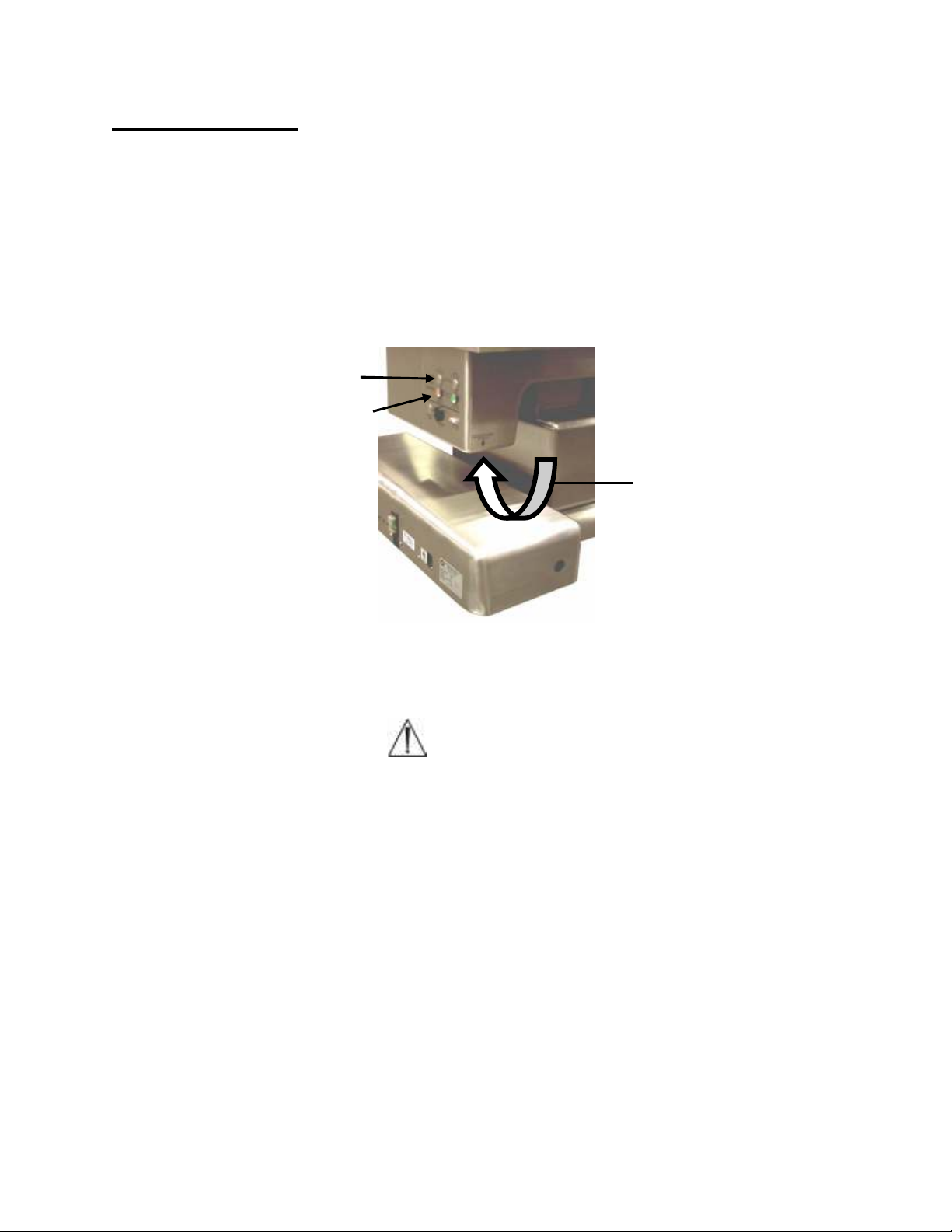
If none of the functions are operating, the floor lock may not be completely deployed.
Press the FLOOR LOCK button until the green LOCKED WHEN LIT indicator is
illuminated.
Floor lock button
Floor lock indicator lights
Figure 10: Floor lock override button
Floor lock override button
(under this surface)
WARNING:
If the floor lock is deployed as evidenced by visual inspection, all four floor lock
feet should be in contact with the floor. Table should not move whether or not
the green indicator is illuminated, and the up/down, lateral roll or trendelenburg
functions do not operate. The floor lock override button can be used to
temporarily bypass the interlock on the floor lock system. This button is located
on the underside of the sheet metal housing at the FLOOR LOCK buttons (see
figure 10). Press and hold this button while simultaneously operating the desired
function on the hand pendant. Once released, no functions will be operable and
this button must be pressed again if subsequent table movement is required.
This override button only powers the height, trendelenburg and lateral roll
functions on the hand pendant and is intended for emergency situations only. If
it becomes necessary to use this feature, call Mizuho OSI Customer Resource
Group immediately to arrange for table service.
MIZUHOSI 2009 NW0510 Rev. D
26
Page 27

CAUTION: Electrical shock hazard exists with access covers removed; use
caution when working in exposed areas.
1. Measure voltage at wall outlet to verify proper AC input is available (120V or 230V).
2. Inspect power supply cord for physical damage, continuity, and adequate resistance.
3. Inspect power switch/circuit breaker:
a. Plastic boot is in good condition.
b. Switch locks in the on and off positions.
c. Green light illuminates when switched on.
4. Verify proper voltage at output ports:
a. Refer to specifications (described above) and interconnect diagram.
5. Verify switchover from AC (mains) to battery operation:
a. With charged battery (24 volts or higher with power switch off) turn power switch
on.
b. Operate up/down function and pull power cord connector from table power-entry-
socket while motor is running.
c. The table should keep moving with only a minor slow-down of motor speed.
6. Repair option for damaged or non-functioning power supply is replacing entire power
supply tray assembly with new unit (see Replacement/Spare Parts List). Field repair
is not recommended.
9.2 Table Functions
Table is “dead”; no functions are operational:
• Verify power cord is plugged into an appropriate AC receptacle and into the power
cord socket (located at the back end of pedestal).
• Verify power switch (located on back end of pedestal) is on. If illuminated, table is
connected to live AC power. If no illumination, table may still operate on internal
battery power (hand pendant control buttons and lights will be illuminated).
• Verify circuit breaker (part of power switch located on table-base panel) is not
tripped off (indicating table power overload condition. Find overload source prior to
resetting). To reset, switch power switch/circuit breaker off, then on.
• Verify component circuit breakers (located on table-base panel) are not tripped off
(indicating component power overload condition. Find overload source prior to
resetting). Observe the three component circuit breaker buttons are not protruding
from circuit breaker access holes.
• Verify floor locks are deployed (all four locking feet make firm contact with the floor).
Observe LOCKED WHEN LIT green light on control panel or FLOOR LOCK ON LED
on hand pendant illuminates.
Floor lock button on control panel not functioning:
• Using the control panel, press and hold the DOWN TO LOCK control button. Verify
the LOCKED WHEN LIT green indicator on the control panel or FLOOR LOCK ON
LED on the hand pendant illuminates.
• Verify the floor locks are deployed (all four locking feet make firm contact with the
floor). Using the control panel, press and hold the DOWN TO LOCK button on the
control panel. Try pressing the UP TO UNLOCK button and then repeat press and
hold the DOWN TO LOCK button.
MIZUHOSI 2009 NW0510 Rev. D
27
Page 28

• Verify power cord is plugged into a properly grounded AC receptacle.
• If on battery power, verify proper charge; observe battery status LED illuminates
green.
• Verify table power switch is on.
• Activate floor lock override; press and hold FLOOR LOCK OVERRIDE button
(located under control panel). While holding floor lock override control button, press
and hold any hand pendant control button for height up, height down, trendelenburg,
reverse trendelenburg, left lateral roll or right lateral roll. Verify function.
Floor lock button on hand pendant not functioning:
• Using the hand pendant, press and hold the FLOOR LOCK button. Verify the
LOCKED WHEN LIT green indicator on the control panel or the FLOOR LOCK ON
LED on the hand pendant illuminates.
• Verify the floor locks are deployed (all four locking feet make firm contact with the
floor). Using the hand pendant, press and hold the FLOOR LOCK button. Try
pressing the FLOOR UNLOCK button and repeat press and hold the FLOOR LOCK
button.
• Verify power cord is plugged into a properly grounded AC receptacle.
• If on battery power, verify proper charge; observe battery status LED illuminates
green.
• Verify the table power switch is on.
• Activate floor lock override; press and hold the FLOOR LOCK OVERRIDE control
button (located under control panel). While holding the FLOOR LOCK OVERRIDE
control button, press and hold any hand pendant control button for height up, height
down, trendelenburg, reverse trendelenburg, left lateral roll or right lateral roll. Verify
function.
Height up or height down not functioning:
• Press and hold the hand pendant HEIGHT UP or HEIGHT DOWN control button.
Observe tabletop movement.
• Verify the hand pendant is properly plugged into a hand pendant receptacle.
Observe hand pendant buttons illuminate green.
NOTE: The table power switch must be turned off before disconnecting or
connecting the hand pendant. Once reconnected, turn power on and deploy floor
locks (all four locking feet make firm contact with the floor).
• With the power switch off, plug the hand pendant into the other hand pendant
receptacle. Turn power switch on. Observe hand pendant buttons illuminate green.
• Verify the power cord is plugged into a properly grounded AC receptacle.
• If on battery power, verify proper charge. Observe battery status LED illuminates
green.
• Verify power switch is on.
• Verify floor locks are deployed (all four locking feet make firm contact with the floor).
Observe LOCKED WHEN LIT illuminates green on the control panel or FLOOR
LOCK ON, LED illuminates on the hand pendant.
• Verify if other hand pendant buttons are functional. If not, replace the hand pendant.
MIZUHOSI 2009 NW0510 Rev. D
28
Page 29

• Call Mizuho OSI Customer Resource Group for service or parts (possible hand
pendant and/or 10 Amp motor-control PCB).
Trendelenburg or reverse trendelenburg not functioning:
• Press and the hold hand pendant TREN or REV.TREN button. Observe tabletop
movement.
• Verify the hand pendant is properly plugged into a hand pendant receptacle.
Observe hand pendant buttons illuminate green.
NOTE: The table power switch must be turned off before disconnecting or
connecting the hand pendant. Once reconnected, turn power on and deploy floor
locks (all four locking feet make firm contact with the floor).
• With the power switch off, plug the hand pendant into the other hand pendant
receptacle. Turn power switch on. Observe hand pendant buttons illuminate green.
• Verify power cord is plugged into a properly grounded AC receptacle.
• If on battery power, verify proper charge; observe battery status LED illuminates
green on the hand pendant.
• Verify power switch is on.
• Verify floor locks are deployed (all four locking feet make firm contact with the floor);
observe LOCKED WHEN LIT indicator illuminates green on the control panel and
the FLOOR LOCK ON LED illuminates on the hand pendant.
• Verify if other hand pendant buttons are functional. If not, replace hand pendant.
• Call Mizuho OSI Customer Resource Group for service or parts (possible hand
pendant and/or 10 Amp motor-control PCB).
Left lateral roll or right lateral roll not functioning:
• Press and hold hand pendant LEFT LATERAL ROLL or RIGHT LATERAL ROLL
control button. Observe tabletop movement.
• Verify hand pendant is properly plugged into a hand pendant receptacle; observe
hand pendant control buttons illuminate green.
NOTE: The table power switch must be turned off before disconnecting or
connecting the hand pendant. Once reconnected, turn power on and deploy floor
locks (all four locking feet make firm contact with the floor).
• With the power switch off, plug the hand pendant into the other hand pendant
receptacle. Turn power switch on. Observe hand pendant buttons illuminate green.
• Verify the power cord is plugged into a properly grounded AC receptacle.
• If on battery power, verify proper charge. Observe battery status LED illuminates
green on the hand pendant.
• Verify power switch is on.
• Verify floor locks are deployed (all four locking feet make firm contact with the floor);
observe LOCKED WHEN LIT indicator illuminates green on the control panel and
the FLOOR LOCK ON, LED illuminates on the hand pendant.
• Verify if other hand pendant buttons are functional. If not, replace the hand pendant.
MIZUHOSI 2009 NW0510 Rev. D
29
Page 30

• Call Mizuho OSI Customer Resource Group for service or parts (possible hand
pendant and/or 10 Amp motor-control PCB).
Top forward or top aft not functioning:
• Press and hold hand pendant TOP FORWARD or TOP AFT control button. Observe
tabletop movement.
• Verify the hand pendant is properly plugged into a hand pendant receptacle.
Observe hand pendant buttons illuminate green.
NOTE: The table power switch must be turned off before disconnecting or
connecting the hand pendant. Once reconnected, turn power on and deploy floor
locks (all four locking feet make firm contact with the floor).
• With the power switch off, plug the hand pendant into the other hand pendant
receptacle. Turn power switch on. Observe hand pendant buttons illuminate green.
• Verify the power cord is plugged into a properly grounded AC receptacle.
• If on battery power, verify proper charge; observe battery status LED illuminates
green on the hand pendant.
• Verify power switch is on.
• Verify floor locks are deployed (all four locking feet make firm contact with the floor);
observe locked when lit light illuminates green.
• Verify if other hand pendant buttons are functional. If not, replace hand pendant.
• Call Mizuho OSI Customer Resource Group for service or parts (possible hand
pendant and/or 10 Amp motor-control PCB).
Top left or top right not functioning:
• Press and hold hand pendant TOP LEFT or TOP RIGHT control button. Observe
tabletop movement.
• Verify hand pendant is properly plugged into a hand pendant receptacle; hand
pendant buttons illuminate green.
NOTE: The table power switch must be turned off before disconnecting or
connecting the hand pendant. Once reconnected, turn power on and deploy floor
locks (all four locking feet make firm contact with the floor).
• With the power switch off, plug the hand pendant into the other hand pendant
receptacle. Turn power switch on. Observe hand pendant buttons illuminate green.
• Verify the power cord is plugged into a properly grounded AC receptacle.
• If on battery power, verify proper charge; observe battery status LED illuminates
green on the hand pendant.
• Verify power switch is on.
• Verify floor locks are deployed (all four locking feet make firm contact with the floor);
observe locked when lit light illuminates green.
• Verify if other hand pendant control buttons are functional. If not, replace the hand
pendant.
• Call Mizuho OSI Customer Service Resource Group for service or parts (possible
hand pendant and/or 10 Amp motor-control PCB).
MIZUHOSI 2009 NW0510 Rev. D
30
Page 31

Top home not functioning on the hand pendant:
• Press and hold hand pendant TOP HOME button. Observe tabletop movement.
• Call Mizuho OSI Customer Resource Group for service or parts (possible hand
pendant and/or 10 Amp motor-control PCB).
Table top home not functioning on the control panel:
• Press and hold TABLE TOP HOME button. Observe tabletop movement.
• Call Mizuho OSI Customer Resource Group for service or parts (possible hand
pendant and/or 10 Amp motor-control PCB).
Return to level not functioning:
• Press and hold hand pendant RETURN TO LEVEL button. Observe tabletop
movement.
• Disorient tabletop by raising height approximately two inches, lateral roll tabletop
and activating trendelenburg approximately five degrees.
• Press and hold hand pendant RETURN TO LEVEL button. Observe roll and
trendelenburg functions level first, and after a three-second delay, tabletop moves
down to its lowest height position and is level.
• Call Mizuho OSI Customer Resource Group for service or parts (possible hand
pendant and/or 10 Amp motor-control PCB).
Battery status LED illuminates red:
• Table battery system requires charging. Charge batteries minimum three (3) hours;
plug power cord into appropriate AC outlet.
NOTE: Power switch must be switched on.
Battery status LED remains illuminated red after battery charging:
• Call Mizuho OSI Customer Resource Group for service or parts.
Joystick control not functioning (allowing longitudinal and lateral tabletop
movement):
• Press and hold ACTIVATION button; red button (black on older tables) must be
activated for joystick operation. Verify function.
• Verify joystick cable-connector is properly plugged into either joystick receptacle.
Observe normal high speed indicator lights illuminate green when corresponding
button pushed.
• Verify Joystick locking lever is completely locked toward pedestal-end to move
tabletop in same direction.
Joystick control moving tabletop in opposite direction:
• Verify joystick locking lever is locked in proper direction, toward pedestal end.
MIZUHOSI 2009 NW0510 Rev. D
31
Page 32

Joystick variable speed operation not functioning:
• Call Mizuho OSI Customer Resource Group for service or parts.
Joystick speed select button not functioning:
• Call Mizuho OSI Customer Resource Group for service or parts.
Joystick:
1. Perform all indicated functions per functional check.
2. If there is no joystick response, inspect for physical damage:
a. Inspect coiled cord for cuts or other damage.
b. Inspect the coiled cord connector pins; verify that they are not bent or broken.
c. Verify the joystick handle provides firm resistance to motion in all directions and
returns to vertical when pushed to one side and released.
d. Inspect the joystick handle support rod (hidden under the rubber boot) for bends.
e. Inspect the red activation-button for damage; verify firm resistance to being
pressed with smooth up and down motion; the button should provide an audible
click at or near the bottom of its stroke.
3. If there is no physical damage:
a. Verify non-function when plugged into either access port.
b. Bypass the internal wiring by plugging the joystick directly into the stepper-
controller PCB DB9-type socket marked joystick.
c. If the table responds properly, the internal table wiring is at fault.
4. Repair option for damaged or non-functioning joystick is replacing entire unit. Field
disassembly is not recommended.
MIZUHOSI 2009 NW0510 Rev. D
32
Page 33
10.0 REMOVAL AND REPLACEMENT OF COMPONENTS
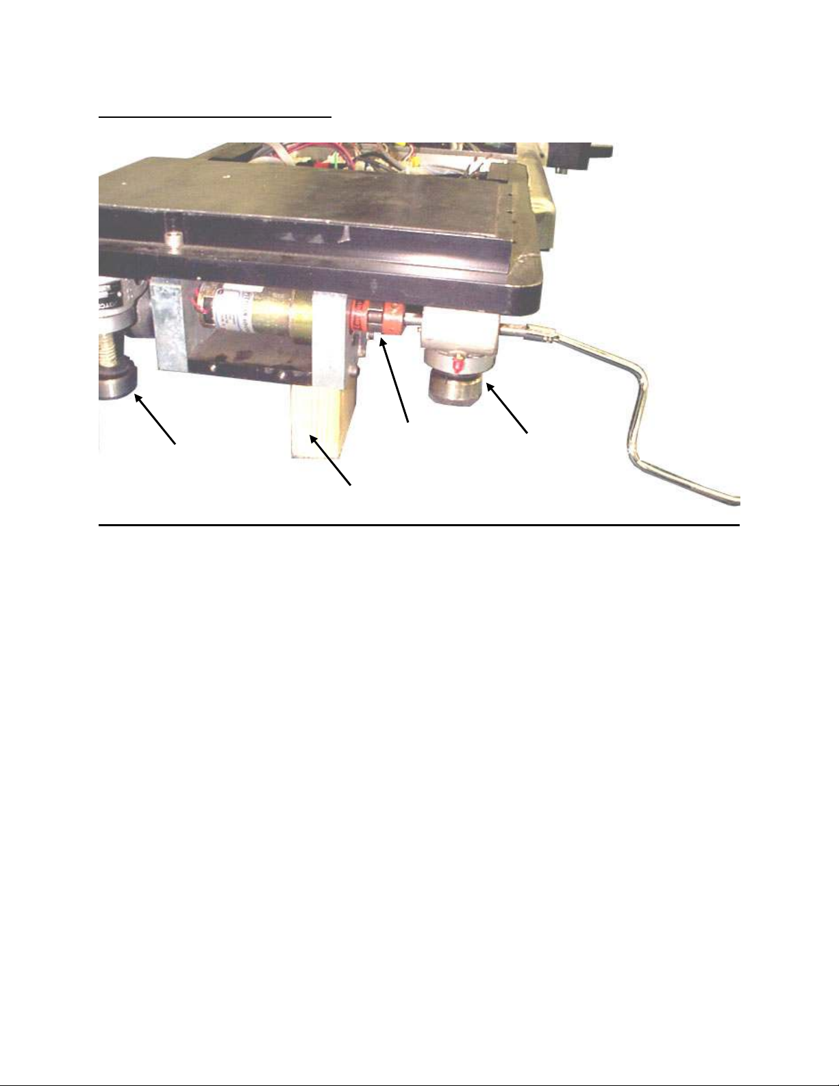
10.1 Floor Lock Foot Actuator
Coupling
Floor lock
(lowered)
and set-screw
Floor lock
(raised)
Crank handle
Support block
Figure 11: Foot end base: Cover removed, raised with support block and crank handle
Replacement procedure:
1. Turn power switch on. The switch illuminates indicating power is to the table.
2. Lock table to floor; press and hold DOWN TO LOCK button until green LOCKED
WHEN LIT light is on.
3. Turn power switch off. Wait 30 seconds for discharge then unplug power cord from
wall outlet.
4. Remove base-access cover from end of table needing replacement.
CAUTION: Electrical shock hazard exists with access covers removed; use
caution when working in exposed areas.
a. Pry off two white plastic access plugs for the floor lock jackscrew using a small
screwdriver.
b. Remove four screws attaching the cover using a 1/8 inch hex key.
c. Remove access cover.
5. Disconnect red wire from battery A positive terminal.
6. Raise end of table using floor lock crank handle (supplied with table).
7. Place 2-1/2 inch high support block under jackscrew floor lock motor mount.
8. Carefully lower table onto support block using floor lock crank handle.
CAUTION: Make certain table remains stable.
9. Raise floor lock off the floor to its maximum height, using floor lock crank handle.
MIZUHOSI 2009 NW0510 Rev. D
33
Page 34
10. Loosen floor lock actuator coupling setscrew using 1/8-inch hex key. Slide coupling
towards actuator.
11. Remove actuator by removing the two socket-head cap screws using 3/16-inch hex
key.
12. Replace floor lock actuator assembly (see Replacement/Spare Parts List section) or
pad as described below.
13. Reassemble in reverse order.
14. Verify proper function using pre-op function check.
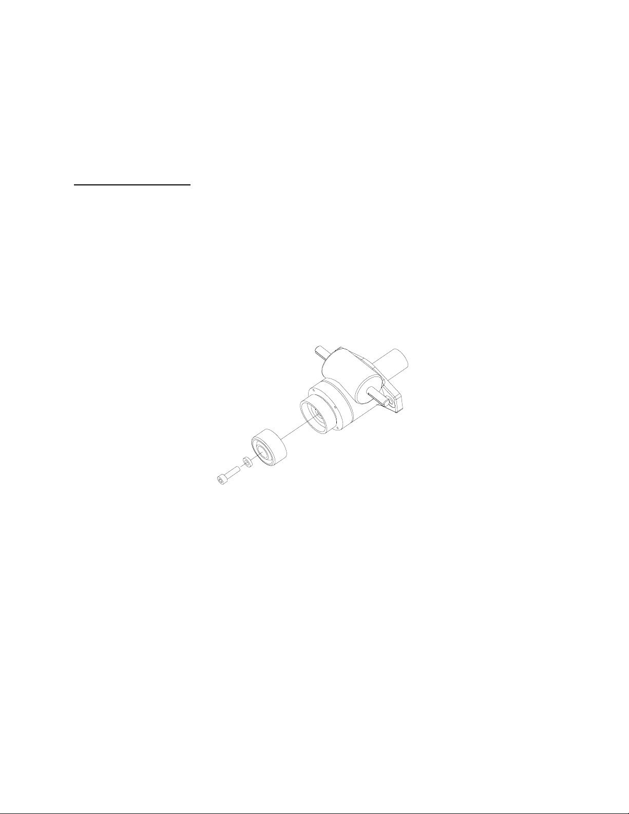
10.2 Floor Lock Pad
If only the floor-lock pad requires replacing, perform the following:
1. Remove brake pad by removing M6-1.00 x 20mm socket-head bolt using 5mm hex
key.
2. If the standard attachment bolt is bent; the first threads may be damaged requiring
replacement with an optional, longer M6-1.00 x 35mm (see Replacement / Spare
Parts List).
3. Install replacement floor lock pad (see Replacement / Spare Parts List) with
attachment bolt and washer using 5mm hex key.
Figure 12: Floor lock actuator assembly
MIZUHOSI 2009 NW0510 Rev. D
34
Page 35

10.3 Power Supply Tray
Battery
-A
Battery
-B
The power supply tray contains the system power supply PCB, transformer, DC
batteries, power switch/circuit breaker, component circuit breakers and power cord
receptacle.
Figure 13: Power supply tray, base cover removed
Figure 14: Base cover and power supply tray removal
MIZUHOSI 2009 NW0510 Rev. D
35
Page 36

Replacement procedure:
1. Turn power switch off. Wait 30 seconds for discharge, then unplug power cord from
wall outlet.
2. Remove pedestal end base cover by removing the six screws using 1/8 in hex key.
CAUTION: Electrical shock hazard exists with access covers removed; use
caution when working in exposed areas.
3. Disconnect red wire from battery A positive terminal.
4. Unplug small 3-wire connector P 11.
5. Unplug 3-wire connector P 15.
6. Unplug 2-wire connector P 16.
7. Remove 3/8-inch hex bolt from ground stud using 9/16-inch wrench and remove top
two green / yellow striped wires.
8. Remove three socket head screws on each side of power supply tray and loosen
two socket-head screws at front of tray using 5/32-inch hex key.
9. Remove power supply tray by carefully lifting out of base casting.
10. Install in reverse order.
10.4 Controller Circuit
The table functions are controlled by input voltage signals from the hand pendant or
control panel to the 10-Amp motor control and stepper controller PCBs located in the
cantilever-end of the base assembly. Voltage from the power supply also is fed to these
controller boards. Interconnect diagrams are given in section 11 for reference.
10-Amp motor control
PCB assembly
Stepper control tray
PCB assembly
Figure 15: 10-Amp motor control PCB and stepper controller tray assemblies
MIZUHOSI 2009 NW0510 Rev. D
36
Page 37

10.5 10-Amp Motor Control PCB
Replacement procedure:
1. Turn the power switch off. Wait 30 seconds for discharge, then unplug power cord
from wall outlet.
2. Remove pedestal end base cover by removing the six screws using 1/8 in hex key.
CAUTION: Electrical shock hazard exists with access covers removed; use
caution when working in exposed areas.
3. Disconnect red wire from battery A positive terminal.
4. Remove cantilever end base cover by removing the four screws using 1/8 hex key.
CAUTION: Electrical shock hazard exists with access covers removed; use
caution when working in exposed areas.
5. Remove cables from 10 Amp motor controller PCB.
NOTE: Cable connectors are not marked, mark as needed.
a. J1 - To stepper controller
b. P1 - To interrupt - to stepper controller/component Interface.
c. P2 - To pc - no connection.
d. P3 - Keypad - extension cable to hand pendant.
e. P4 - Output - no connection.
f. P5 - Power in - power cable to DC power supply.
g. P6 - White marked cable to trendelenburg actuators.
h. P7 - To tilt sensor assembly.
i. P8 - Blue marked cable to trendelenburg actuators.
j. P10 - Orange marked cable to tilt actuator.
k. P11 - To tilt sensor assembly.
l. P12 - Yellow marked cable to vertical actuator.
m. P13 - No connection.
n. P15 - No connection.
o. P17 - No connection.
p. P18 - Input - no connection.
6. Remove the two #10 socket head screws attaching the 10 Amp motor controller
PCB mounting bracket, located under the PCB.
7. Lift the mid section base cover and remove the two #10 socket head screws
attaching the 10-Amp motor controller PCB mounting bracket.
8. Carefully lift out the two #10 socket-head screws attaching the 10 Amp motor
controller PCB assembly.
9. Reassemble in reverse order.
MIZUHOSI 2009 NW0510 Rev. D
37
Page 38

10.6 Stepper Controller Tray
Figure 16: Stepper control tray assembly
Stepper control
interface PCB
Y-Axis
stepper PCB
X
Y
X-Axis
stepper PCB
Replacement procedure:
1. Turn the power switch off. Wait 30 seconds for discharge, then unplug power cord
from wall outlet.
2. Remove pedestal end base cover by removing the six screws using 1/8 in hex key.
WARNING:
Electrical shock hazard exists with access covers removed; use caution when
working in exposed areas.
3. Disconnect red wire from battery A positive terminal.
4. Remove cantilever end base cover by removing the four screws using 1/8 hex key.
WARNING:
Electrical shock hazard exists with access covers removed; use caution when
working in exposed areas.
5. Remove cables from stepper controller PCB.
NOTE: Cable connectors are not marked, mark as needed.
a. J1 and J2 - To X & Y stepper drivers.
b. P1 - Joystick input.
c. P2 - Com port.
d. P3 - Power in.
e. P4 - Power out.
MIZUHOSI 2009 NW0510 Rev. D
38
Page 39

f. P6 - Senders
g. P7 - Analog I/O
h. P8 - Digital I/O
6. Remove cables from stepper driver PCBs.
NOTE: Y stepper PCB is above and cables marked white, X stepper below marked
black.
a. J2 - Power
b. J3 - Motor
7. Remove the ground wires from the ground stud.
8. Remove the two tray mounting screws closest to the table pedestal using 5/16 in hex
key.
9. Loosen the two, horizontal, tray mounting screws using 5/16 in hex key.
10. Carefully lift out the controller tray.
11. Reassemble in reverse order.
X-Y Axis stepper motor high speed adjustment procedure:
With pedestal end base cover removed and using the joystick to control the stepper
motors and using a stopwatch to time the total travel time, take the following actions:
1. Position each motor at one end of its travel using the joystick.
2. Switch the joystick to high speed and verify high speed green light is
illuminated. Without activating the button on the top of the joystick, move the joystick
in the extreme opposite direction.
3. Press the button and the start time on the stopwatch.
a. X-Axis motor (large motor), travel time = 4.7 (four point seven) seconds +/- 1.3
(one point three) seconds.
NOTE: If the motor does not meet this requirement, adjust R86 on stepper controller
PCB and re-test.
b. Y-Axis motor, travel time = 4.7 (four point seven) seconds +/- 1.3 (one point
three) seconds.
NOTE: If the motor does not meet this requirement adjust R87 on stepper controller
PCB and re-test.
4. Using the hand pendant, joystick and control panel, run all functions through the
entire range five times.
Table floor lock system adjustment procedure:
Adjust floor lock potentiometers to read .65V (point six five) +/- .02V (point zero two)
1. Using a voltmeter connect ground probe to TP-2 (analog ground).
2. Connect positive probe to TP-3 and observe voltage.
3. Adjust trim pot R11 until voltage reads .65V (point six five) +/- .02V (point zero two).
4. Repeat steps for TP-4 and R19, TP-5 and R27, TP6 and R35.
MIZUHOSI 2009 NW0510 Rev. D
39
Page 40
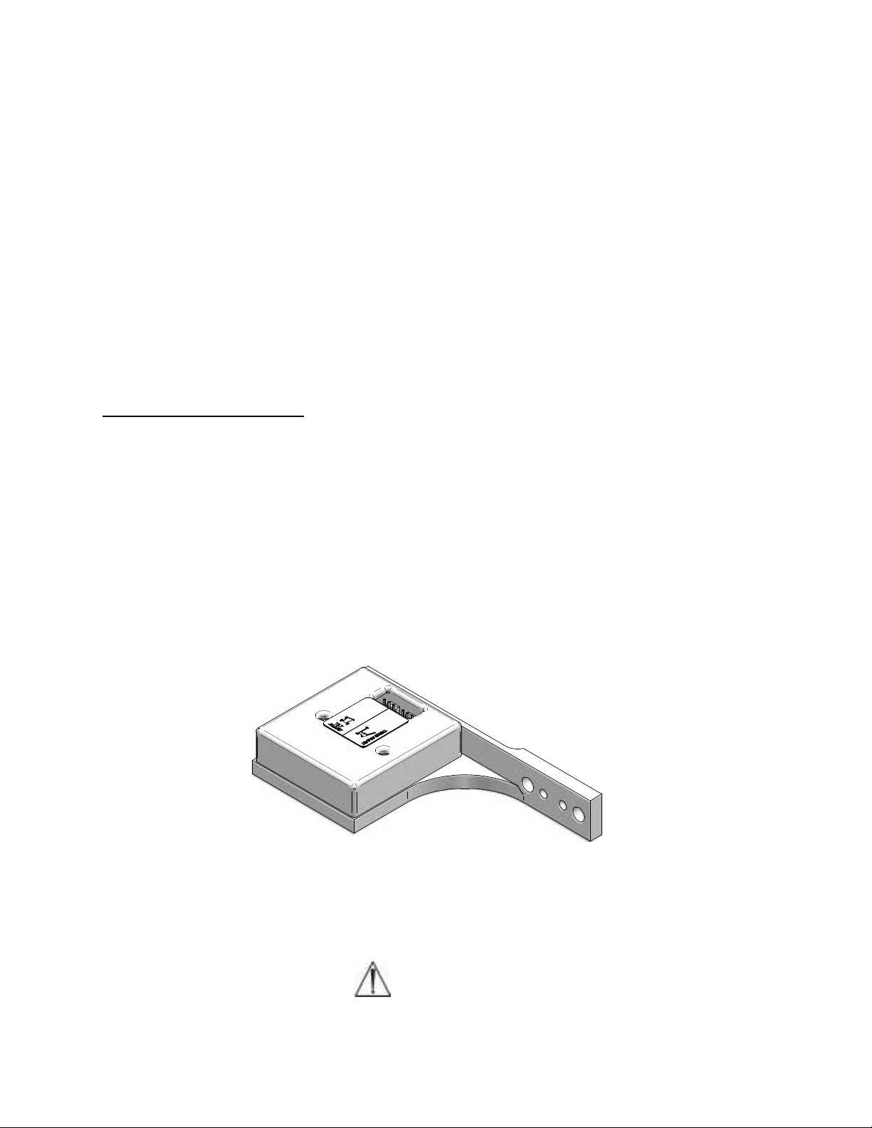
Table floor lock system test procedure:
Using hand pendant and control panel, operate floor lock and unlock buttons through
their full range and verify that
1. All four floor lock motors move while the button is pressed and all motors stop when
the button is released.
2. The floor lock LOCKED WHEN LIT light illuminates green when all four motor feet
are extended and all motors stop.
3. The floor lock STOWED WHEN LIT light illuminates amber when all four motor feet
are retracted and motors stop.
4. After the light, amber or green, illuminates all motors stop even when the button is
held.
NOTE: If the floor lock motors appear to be out of sync (excessive travel distance
between the group), this may indicate problems with the motor, gearbox or the
stepper controller PCB.
10.7 Tilt Sensor Actuator
Tilt level sensor assembly:
The tilt sensor controls the trendelenburg and tilt table levels. This sensor assembly is
protected by the X-Y stage and tilt covers. Removal of the covers requires movement
of the table system before, during and after the disassembly process. It is
recommended that the power be turned off and the table unplugged, during the removal
of the covers. After removal, and/or assembly of the tilt level sensor, a calibration
sequence, extreme caution must be taken to ensure safety to the operator and to the
table. Following are the steps required for access, removal, replacement and/or
calibration:
Figure 17: Tilt sensor assembly
Top (X-Y Stage) cover removal:
WARNING:
The following procedure requires removing components with the table on, use
extreme caution.
MIZUHOSI 2009 NW0510 Rev. D
40
Page 41

1. Turn power switch on. The green light illuminates.
2. Press and hold DOWN TO LOCK button until green LOCKED WHEN LIT light
illuminates.
3. Move tabletop to highest position and maximum left lateral roll using hand pendant.
4. Move tabletop to maximum left translation position using joystick.
5. Remove left Y-stop bracket (the L-shaped bracket with rubber bumper) by removing
two screws with 5/32 hex key.
6. Move tabletop to maximum right lateral roll using hand pendant.
7. Move tabletop to maximum right-translation position using joystick.
8. Remove right Y-stop bracket (opposite left Y-stop bracket) by removing two screws
with 5/32 hex key.
9. Remove X-Y stage cover by removing four screws, two on each side, using 1/8 hex
key.
10. Turn power off and unplug table.
11. Slide X-Y stage cover off end of tabletop.
Left Tilt Cover Removal (The Bell Shaped Housing):
WARNING:
The following procedure requires removing components with the table on, use
extreme caution.
NOTE: On some older tables, front X-Y stage cover must be removed to access one 440 mounting screw. Do not replace this screw during reassembly.
1. Remove seven flat-head screws, using 1/16 inch hex key.
2. Remove three screws located on top surface of left tilt cover using 1/8 inch hex key.
3. Plug table in and turn power on.
4. Move tabletop with joystick to maximum left transitional position. Move tabletop, to
place casting recess (viewed best from below) for best screw clearance and easiest
access.
5. Turn power switch off. Wait 30 seconds for discharge, then unplug power cord from
wall outlet.
6. Disconnect red wire from battery A positive terminal.
7. Remove left tilt cover.
WARNING:
To prevent damage to the sensors use care removing or replacing this cover.
Replacement procedure:
1. Cut any cable ties holding the existing tilt sensor wire harness to the tilt sensor
bracket.
2. Gently pull the two sets of wires from the tilt sensor.
NOTE: The color coding: White-marked connector goes to white-marked tilt adjust
socket. Black-marked connector goes into black-marked trend adjust socket.
3. Remove the tilt sensor by removing two, 1/4-20x1/2 in. cap-head screws using 3/16
hex key.
MIZUHOSI 2009 NW0510 Rev. D
41
Page 42

4. Replace in reverse order. Attach harness to sensor bracket, as needed, with small
nylon cable tie. Use care to prevent possible damage by moving parts.
Tilt sensor calibration:
NOTE: Use a bubble level resting on the tabletop as a level gauge. The level sensor
adjustment screws are accessed from the top of the unit. A two degree maximum deadband exists for each axis. For return to level to function, the tabletop must be outside of
this dead-band.
1. Turn power switch on. The green light illuminates.
2. Press and hold DOWN TO LOCK button until green LOCKED WHEN LIT indicator
illuminates.
3. Raise the tabletop to a comfortable level.
4. Push the LEFT LATERAL ROLL or RIGHT LATERAL ROLL buttons to level
tabletop.
5. Push the LEFT LATERAL ROLL button to tilt the tabletop more than five degrees.
6. Push the RETURN TO LEVEL button to level the tabletop; note the degree of level.
7. Push the RIGHT LATERAL ROLL button to tilt the tabletop more than five degrees.
8. Push and hold the RETURN TO LEVEL button to level the tabletop; note the degree
of level.
9. Turn the tilt adjust screw a partial turn.
NOTE: Clockwise will stop the tabletop more to the right, counter-clockwise will stop the
tabletop more to the left. The tabletop will overshoot each stopping point, requiring
"splitting the difference" to adjust for proper balance.
10. Test the adjustment by:
a. Push the LEFT LATERAL ROLL button to tilt the tabletop to maximum.
b. Push the RETURN TO LEVEL button to level the tabletop; note the degree of
level.
c. Push the RIGHT LATERAL ROLL button to tilt the tabletop to maximum.
d. Push the RETURN TO LEVEL button to level the tabletop; note the degree of
level.
11. Continue adjustments until the tabletop stops from either maximum lateral roll at the
same offset from zero.
12. Trendelenburg / reverse-trendelenburg calibration (TREN/REV.TREN).
a. Repeat steps of left and right lateral roll calibration using TREN/REV.TREN
buttons on the hand pendant.
13. Turn power switch off. Wait 30 seconds for discharge, then unplug power cord from
wall outlet.
14. Disconnect red wire from battery A positive terminal.
15. Attach left tilt cover.
WARNING:
Use care replacing this cover to prevent damage to the sensors.
16. Place the left tilt cover in its original position.
a. Install the three screws attaching left tilt cover, located on top surface, using 1/8
hex key.
MIZUHOSI 2009 NW0510 Rev. D
42
Page 43

b. Move the tabletop with the joystick to maximum left position for best screw
clearance and easiest access.
c. Install the seven screws attaching the left and right tilt covers using a 1/16 inch
hex key.
17. Attach X-Y stage cover.
a. Place the X-Y stage cover onto the tabletop.
b. Install the four screws attaching the X-Y stage cover using a 1/8 inch hex key.
c. Install the two flat-head screws attaching the left Y-stop bracket using 5/32 inch
hex key.
d. Install the two flat-head screws attaching the right Y-stop bracket using 5/32 inch
hex key.
MIZUHOSI 2009 NW0510 Rev. D
43
Page 44

11.0 TECHNICAL DRAWINGS AND PARTS LISTS
11.1 Electrical Interconnect Diagram, 120 VAC
AC
60Hz
110V
9600-750
SW
5A
1 & 2
PINS
JUMPER
6800-204
P12
P10
E12
PCB
6800-250
6800-200
SUPPLY SUPPLY
POWER SUPPLY TRAY
P16
24VDC
15A
P13
24VDC
10A
10A10A
24VDC
E15
THRU
P15
P14
GND
24VDC
6800-205
6800-206
X STEPPER MOTOR
Y STEPPER MOTOR
LIMIT SWITCH ARRAY
LIMIT SWITCH ARRAY
6800-198
+24V
6800-193
P6
P3
P2
STEPPER CONTROLLER
P8
+24V
P4
6800-190
INTERFACE BOARD
J1
J2
LOCK
FLOOR
MOTORS
24V
24V 24V24V
6800-197
GND
+24V
+24V
P5
NV0337
P1
6800-150
JOYSTICK
6800-238
HAND PENDANT CONTROL
CONNECT TO
EITHER PANEL
AUXILIARY PANEL
6800-192
CONNECT TO
EITHER PANEL
INPUT FOR
FRONT
HAND CONTROL
9 PIN D SUB
FOR JOYSTICK
9650-431A
6800-201
PLUS
BLU/BRN
6800-194
6800-274 OR 6800-275
P5
+
P8
P6
24V
MADE PER 6800-320
24V
P12
24V
24V
MADE PER 6800-320
MADE PER 6800-320
24V
24V
BLACK SHRINK WRAP
CAPACITOR
10,000UF
50V DC
(PART OF
-
CONTROL PCB
6800-240
10 AMP MOTOR
P7
BLK SHRINK WRAP
WHT SHRINK WRAP
P1
J1
P1
P11
P10
24V
6800-185
MADE PER
TILT
ACTUATOR
PCB / CABLE
BLK/RED
24V
P2
6800-195
WHITE SHRINK WRAP
J2
J3
6800-196
6800-203
2 PLCS
6800-196)
NV0564P36800-248
5V, 12V , 100mA
BLU/BLK
6800-199
6800-171
6800-171
6800-171
6800-201
J1
J2
PCB
X-AXIS
STEPPER DRIVE
J1
PCB
Y-AXIS
STEPPER DRIVE
GND
GND
J3
6800-202
NV0564
9600-450
6800-251
STEPPER-CONTROLLER/DRIVER TRAY ASSEMBLY
SWITCH
" DOWN TO LOCK"
GRY/BLKWHT/BLK
SWITCH
"UP TO UNLOCK"
9 PIN D SUB
GREEN LED
FOR JOYSTICK
"LOCKED WHEN LIT"
GRN/BLK
YEL/BLK
"STOWED WHEN LIT"
INPUT FOR
HAND CONTROL
BRN/BLK
SWITCH
AMBER LED
"TABLETOP HOME"
BLU/BLK
REAR
FLOOR LOCK
CONTROL PANEL
SWITCH
"FLOOR LOCK OVERRIDE"
TILT
TILT
REVERSE-
ACTUATOR
ACTUATOR
TRENDELENBURG
TRENDELENBURG
SENSOR
6800-247
ACTUATOR
ASSY
VERTICAL
MIZUHOSI 2009 NW0510 Rev. D
RIGHT
LEFT
6800-80
ACTUATOR
NV0579
NV0579
LIMIT SWITCH
Y-AXIS
STEPPER
LIMIT SWITCH
X-AXIS
6800-50
MOTOR
6800-51
MOTOR
STEPPER
44
Page 45

11.2 Electrical Interconnect Diagram, 230 VAC
J1
J2
MIZUHOSI 2009 NW0510 Rev. D
45
Page 46
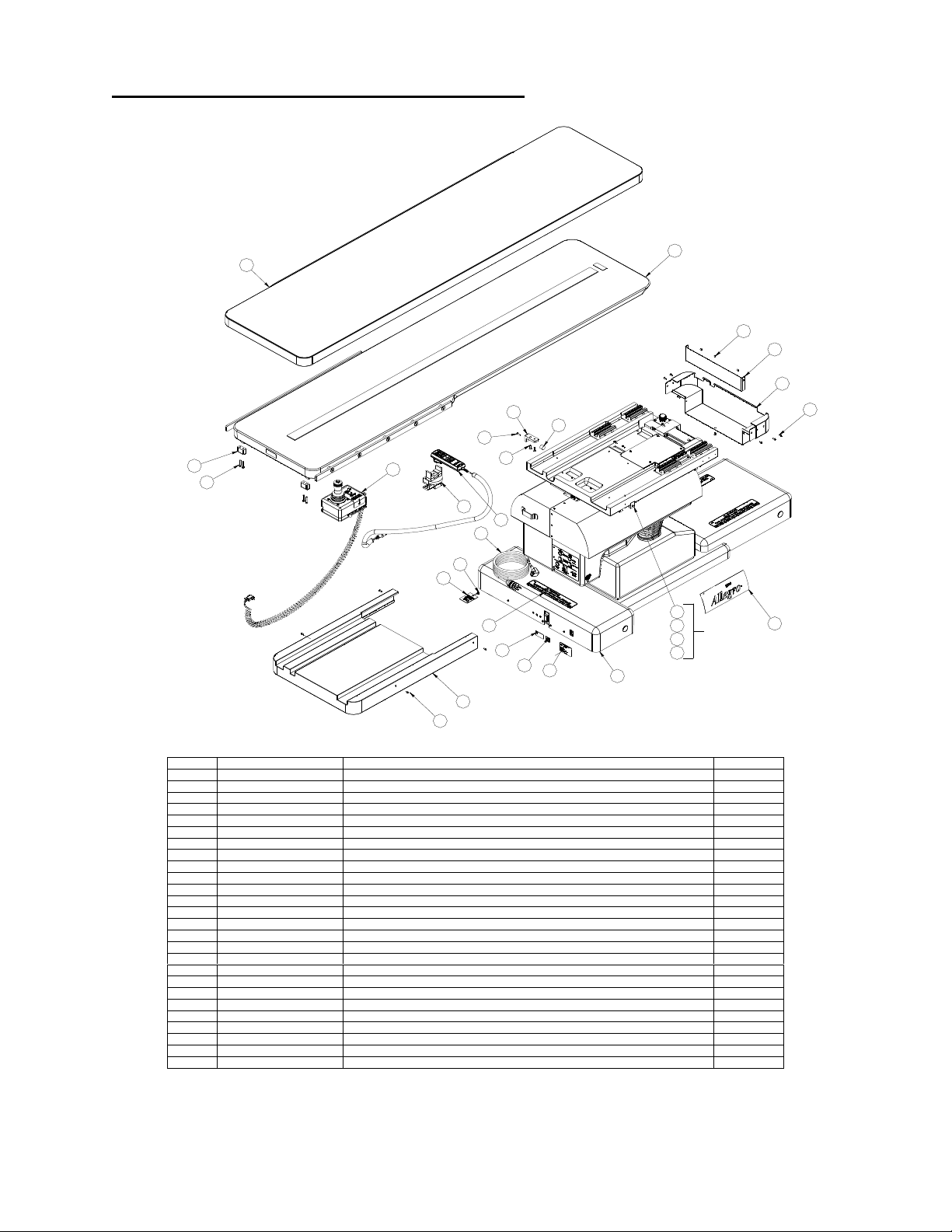
11.3 Top Level Table Assembly Exploded View
4
32X
114X
9
26
12
14
202X
212X
224X
5
18
253X
15
6
4X
10
2
24 3X
8
7
10 7X
23 2X
20
21
(REF)
22
13
16
1
23
17 2X
MIZUHOSI 2009 NW0510 Rev. D
26 6800-290 HAND PENDANT SWIVEL MOUNT, ASSY 1
25 NP1816 WARNING LABEL, NOT FOR STORAGE 3
24 NG0752 #10-32 PEM SELF CLINCHING SS 3
23 NB0331 RUBBER BUMPER #10 FEMALE THREAD 2
22 AAAW075BAC 1/4-20 X .75 SST FLHD SKT SCR 4
21 AAAT075BAC #10-32 UNF X .75 LG, SST FL HD SKT SCR 2
20 6800-175 BRACKET, BUMPER STOP MOUNT, Y AXIS 2
19 NW0367 USER GUIDE, ALLEGRO TABLE 2
18 9600-750 HOSP. GRADE PW R CORD, 10FT, RT ANGLE 1
17 NP1858 LABEL, 6800 ALLEGRO 2
16 NP1625 6800 TABLE SERIAL NUMBER LABEL 1
15 NP1560 LABEL, ETL LISTING 1
14 NP1559 GROUNDING LABEL 1
13 NP1551 LABEL, MEDICAL, TYPE B 1
12 NC0356 CABLE TIE, 4" BLACK 1
11 AAM6030CAA M6-1.00 X 30mm SKT HD CAP SCR, GR12.9 4
10 AAAT037AAC #10-32 UNF X .37 SST BT HD SKT SCR 11
9 6800-280 ASSY, JOYSTICK II, HEAVY DUTY 1
8 6800-279 X-Y STAGE COVER, X-MOTOR COVER (PLASTIC) 1
7 6800-278 X-Y STAGE COVER, FWD (PLASTIC) 1
6 6800-277 BOTTOM PLATE 1
5 6807-3 HANDPENDANT ALLEGRO 1
4 6800-140 ASSEMBLY, TOP PAD, 4 WAY FLOAT TABLE 1
3 6800-66 STOP, TABLE TRAVEL, X-AXIS 2
2 6800-5 ASSY, TABLE TOP, 4 WAY FLOAT TABLE 1
1 6800-4 FINAL BASE ASSEMBLY 1
ITEM PART NO DESCRIPTION QTY
46
Page 47

11.4 Table Sub Assembly Parts List
75 AAAW050CA 1/4-20 X .50 HEX HD CAP SCR 2 150 MZNP1811 LABEL, EQUIPOTENTIAL 1
74 AAAW050BAC 1/4-20 X .50 SST FLHD SKT SCR 4 149 AM062200 .625 DIA X 2.00 SST DOWEL PIN 2
73 AAAT125CAC #10-32 X 1.25 SST CAP HD SKT SCR 5 148 ADAHEC #4 NYLOCK NUT, SST 8
72 AAAT125BAC #10-32 X 1.25 SST FLHD SKT SCR 1 147 6850-1012 INTERNAL HAND PENDANT CABLE EXTENSION 1
71 AAATO75HA # 10-32 X .25 SST SKT SET SCR 7 146 NP1837 BATTERY ORIENTATION LABEL 1
70 6800-276 X-RING DOOR, FRONT 1 145 NP1851 BATTERY INSTRUCTION PICTURE LABEL 1
69 AAAT075AAC #10-32 X .75 BTN HD SKT SCREW S.S. 4 144 NP1850 BATTERY INSTRUCTION LABEL 1
68 AAAT050HAC #10-32 X .50 SST SKT SET SCR 1 143 6850-1014 BATTERY CABLE SET 1
67 AAAT050BAC #10-32 X .50 SST FLHD SKT SCR 2 142 NV0711 MOLEX SOCKET CRIMP 28-22 AWG 16
66 AAATO50AAC #10-32 X .50 SST BTN HD SKT SCR 12 141 NV0630 CONNECTOR HOUSING, MALE, 8 CIRCUIT 39-01-2080 4
65 AAAT037CAC #10-32 X .37 SST CAP HD SKT SCR 8 140 6 800-76 TILT WORM GEAR SHIM, .005 1
64 AAATO37AAC #10-32 X .37 SST BTN HD SKT SCR 55 139 6800-274 10 A MOTOR CONTROL POWER CABLE 1
63 AAAT031AAC #10-32 X .31 SST BTN HD SKT SCR 34 138 6800-248 CABLE ASSY. ,FLAT RIBBON M-F DB9 1
62 AAAT025HJA #10-32 X .25 SELF LOCKING SKT SET SCR 2 137 6800-246 TILT SENSOR WIRE HARNESS 1
61 AAAT025AAC #10-32 X .25 SST BTN HD SKT SCR 4 136 6800-203 CABLE ASSY, Y-AXIS STEPPER MOTOR CONTROL 1
60 AAAMO37CAC #6 -32 X .37 SST CAP HD SKT SCR 1 135 6800-202 CABLE ASSY, X-AXIS STEPPER MOTOR CONTROL 1
59 AAAM018AAC #6-32 X .188 SST BTNHD SKT SCR 2 134 6800-199 DIGITAL I/O WIRE HARNESS 1
58 AAAH025AAC #4-40 X .25 SST BTNHD SKT SCR 8 133 6800-198 SENSOR ARRAY WIRE HARNESS 1
57 AAAH031BAC #4-40 X .31 SST FLHD SKT SCR 21 1 32 6800-197 FLO OR LOCK HARNESS ASS. 1
56 AAAH018BAC #4-40 X .188 SST FLHD SKT SCR 6 131 6800-193 CABLE ASSY, PWR SPL TO STEPPER CONTROLLER 1
55 9650-231 ½ RUBBER CUSHIONED STEEL LOOP CLAMP 7 130 6800-119 TILT WORM GEAR SHIM .0239 THICK 2
54 9650-227 .375 INCH PLASTIC CABLE CLAMP 10 129 6800-118 TILT WORM GEAR SHIM .007 THICK 2
53 6800-271 BELLOWS MOUNT 2 128 9650-225 .25 INCH PLASTIC CABLE CLAMP 1
52 6800-270 TILT COVER, RIGHT 1 127 NV0649 .75 INCH PLASTIC CABLE CLAMP 3
51 6800-269 TILT COVER, LEFT 16 126 6800-185 ACTUATOR POWER CORD 1
50 6800-268 COLUMN SKIRT, FIXED RIGHT 1 125 NV0653 HORIZONTAL MOUNTING CLIP, CAPACITOR 2
49 6800-267 COLUMN SKIRT, FIXED LEFT 1 124 6800-192 JOYSTICK Y CABLE 1
48 6840-51 X-RING COVER, RIGHT 1 123 NV0650 1 INCH PLASTIC CABLE CLAMP 5
47 6840-50 X-RING COVER, LEFT 1 122 6800-196 CABLE ASSEM, X-AXIS STEPPER MOTOR 1
46 6800-260 BELLOWS SUPPORT 2 121 NV0587 PUSH BUTTON, MOM., SST 4
45 6800-259 BE LLOWS 2 120 6850-195 FOAM BATTERY BLOCK 2
44 6800-4250 ASSEMBLY CONTROLLER TRAY (STEPPER) 1 119 NV0801 BATTERY 12V, 12 A H SONNENSCHEIN ES12-12 2
43 6800-250 POWER SUPPLY TRAY ASSEMBLY 1 118 6850-1011 2 OUTPUT INT. HAND PEND. CBL. W/NANABOSHI 1
42 6800-249 TILT SENSOR SPACER 1 117 NV0259 3/8 IN RUBBER CUSHIONED STEEL LOOP CLAMP 7
41 6800-247 TILT SENSOR ASSEMBLY 1 1 16 NP1549 ELECTRICAL GROUND LABEL 2
40 6800-244 CAPACITOR MOUNT PLATE 1 115 NL1255 ACTUA TOR, ELEC., 100MM, LINAK 2
39 6850-1020 ASSY, 10 AMP MOTOR CONTROL 1 114 NG0753 JACKSCREW #4-40 X 187 X .31 THD W/WASH & NUT 6
38 6800-230 ASSEMBLY, MANUAL FLOOR LOCK CRANK 1 113 NG0752 #10-32 PEM SELF CLINCHING SS 8
37 6800-229 X-RING WITH BUSHINGS ASSY 1 112 NB0339 EAGLE PLASTIC NYLON HOLE PLUG ø1.00 4
36 6800-208 FLOOR LOCK LED YELLOW 1 111 6800 -195 CABLE ASSEM, Y-AXIS STEPPER MOTOR 1
35 6800-207 FLOOR LOCK LED GREEN 1 110 NA0190 THOMSON RAIL 25MM X 508MM 2
34 6800-206 Y-AXIS SENSOR ARRAY ASSY AND WIRING DIA. 1 109 NA0189 THOMSON 25MM CARRIAGE STD LENGTH 4
33 6800-205 X-AXIS SENSOR ARRAY ASSY AND WIRING DIA. 1 108 NA0186 THOMSON CARRIAGE 25MM LONG 4
32 6800-187 BRACKET, TABLE RETURN TO CENTER FLAG, Y-AXIS 1 107 KA0060400 1/16 X 4 ½ NEOPRENE RUBBER W/ADH 24
31 6800-186 BRACKET TRAVEL STOP FLAG, Y-AXIS 2 106 AJ0114 RETAINING RING EXTERNAL 1” DIA, SST 4
30 6800-171 TILT MOTOR LIMIT SWITCH ASSY 1 105 AE040081A WASHER, FLAT .400 X .81 X .051 2
29 NV0337 10 FT EXTENSION CABLE M-F DB9 1 104 AE037075H WASHER, FLAT HEAVY DUTY .38 ID .75 OD 4
28 6800-174 BRKT, TILT MTR LIM SW MNT 2 103 AE037068BD WASHER, LOCK .38 X .68 HEAVY DUTY 4
27 6800-173 PC BOARD MOUNT, TILT MOTOR 1 102 AE 019050KF SHOULDER WASHER #10 NYLON 4
26 6800-148 CABLE TRAY, Y-RING 1 101 AE018037D STAR LOCK WASHER, INTERNAL, .18 X .37 3
25 6800-133 BASE COVER, FRONT 1 100 MZA30108030 8MM HEX NUT 10
24 6800-132 BASE COVER, BACK 1 99 ADATA #10-32 HEX NUT 3
23 6800-130 BASE COVER, MID SECTION 1 98 6850-1010 CABLE BATTERY MONITORING 1
22 6800-129 COLUMN SKIRT FLOATING 1 97 AC012025 POP RIVET, .12 X .25 LG 8
21 6800-127 COLUMN SLIDER COVER 1 96 AAM8035CAN M8 X 35 SOCKET HEAD CAP SCREW CLASS 12.9 8
20 6800-99 PIN, TRENDELENBURG 2 95 AAM8030CA M8 X 3 0 SOCKET HEAD CAP SCREW CLASS 12.9 14
19 6800-98 PIN, TILT, BACK 1 94 AAM8030BAN M8 X 30 FLAT HEAD SOCKET SCREW CLASS 12.9 3
18 6800-97 PIN, TILT, FRONT 1 93 AAM8025CAN M8 X 25 SOCKET HEAD CAP SCREW CLASS 12.9 7
17 6800-96 SWIVEL BRACKET MOUNT WASHER 2 92 AAM6030CAA M6-1.00 X 30MM SKT HD CAP SCR, CLASS 12.9 18
16 6800-95 PRESSURE PLATE, TILT ACTUATOR MOUNT 1 91 AAM6025CAN M6-1.00 X 25MM SKT HD CAP SCR, CLASS 12.9 16
15 6800-94 SWIVEL BRACKET ADJUSTMENT BRACKET 1 90 AAM10045FA 10MM DIA. X 45MM LG, SKT HD SHLDR SCR 1
14 6800-90 SWIVEL BRACKET WELDMENT, TILT 1 89 AAM10035FA 10MM DIA. X 35MM LG, SKT HD SHLDR SCR 1
13 6800-80 ASSEMBLY, TILT ACTUATOR 1 88 AAM10030FA 10MM DIA. X 30MM LG, SKT HD SHLDR SCR 3
12 6800-79 TILT AXIS WORM GEAR 1 87 AABF125CA ½-13 X 1.25 CAP HD SKT SCR 2
11 6800-77 TILT WORM GEAR SHIM, .010 2 86 AABB075HA 3/8-16 X .75 SCK SET SCR 1
10 6800-75 TILT WORM GEAR SHIM, .002 1 85 AABB175DDA 3/8 – 16 X 1.75 HEX HD CAP SCR, GRADE 8 1
9 6800-73 X-Y CORD COVER PLATE 1 84 AABB175CAN 3/8-16 UNC X 1.75 CAP HD SKT SCR GR 8 3
8 6800-72 GEAR RACK, Y-AXIS, X-Y COUPLER 1 83 AABB125CAC 3/8-16 UNC X 1.25 SST CAP HD SKT SCR 4
7 6800-70 X-Y COUPLER, CASTING MACHINED 1 82 AABB100CAC 3/8-16 X 1.0 SST CAP HD SKT SCR 2
6 6800-54 SHIM, 1.00 DIA PIN 6 81 AABB075CAC 3/8-16 X .75 SST CAP HD SKT SCR 2
5 6800-51 ASSY, STEPPER MOTOR AND GEAR BOX Y-AXIS 1 80 AABB075CAA 3/8-16 X .75 CAP HD SKT SCR GRADE 8 3
4 6800-50 ASSY, STEPPER MOTOR AND GEAR BOX X-AXIS 1 79 AAAY350DD 5/16-18 X 3.5 HEX HEAD CAP SCREW 2
3 6800-38 Y-RING MACHINED 1 78 AAAW125CA ¼-20 X 1.25 CAP HD SKT SCR 2
2 6800-37 TRENDELENBURG ADJUSTMENT LEVER, X-RING 1 77 AA AW075CA ¼-20 X .75 CAP HD SKT SCR 3
1 6800-7 BASE FEET AND COLUMN SUBASSEMBLY 1 76 6800 -273 X RING DOOR, REAR 1
ITEM PART NO. DESCRIPTION QTY ITEM PART NO. DESCRIPTION QTY
MIZUHOSI 2009 NW0510 Rev. D
47
Page 48
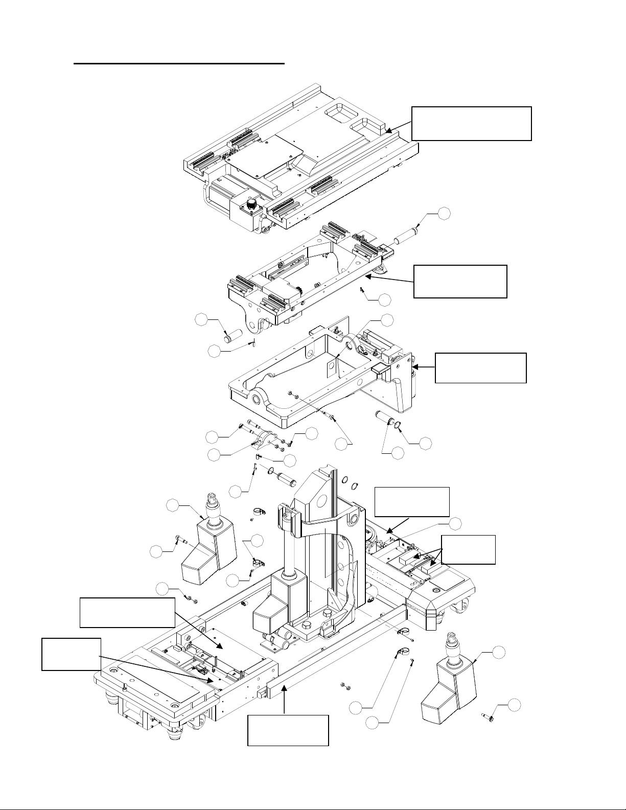
11.5 Table Assembly Exploded View
NOTE: Numbers correspond to item numbers on parts list in section 11.4.
X-Y Coupler assembly
19
Y-Ring assembly
68
882X
1004X
10 Amp controller
18
71
6
X-Ring assembly
90
2
77
1152X
123 4X
100
88
86
106 4X
20 2X
Power supply
43 (REF)
Batteries
634X
Stepper-
115 (REF)
controller
123(REF)
63(REF)
Base assembly
88 (REF)
MIZUHOSI 2009 NW0510 Rev. D
48
Page 49

11.6 Base Cover Assembly Exploded View
39
NOTE: Numbers correspond to item numbers on parts list in section 11.4.
Base Assembly Exploded View
128
692X
1073" X 4.5"
21
532X
107 3" X 4.5"
614X
22
45
63 6X
54 5X
64 6X
55 2X
63 2X
40
102 4X
59 2X
125
66 2X
111
122
107 3" X 13"
50
642X
576X
642X
633X
25
127 3X
49
23
662X
44
64 2X
107 REF
64 4X
24
112 4X
107 REF
1
64 4X
MIZUHOSI 2009 NW0510 Rev. D
49
Page 50
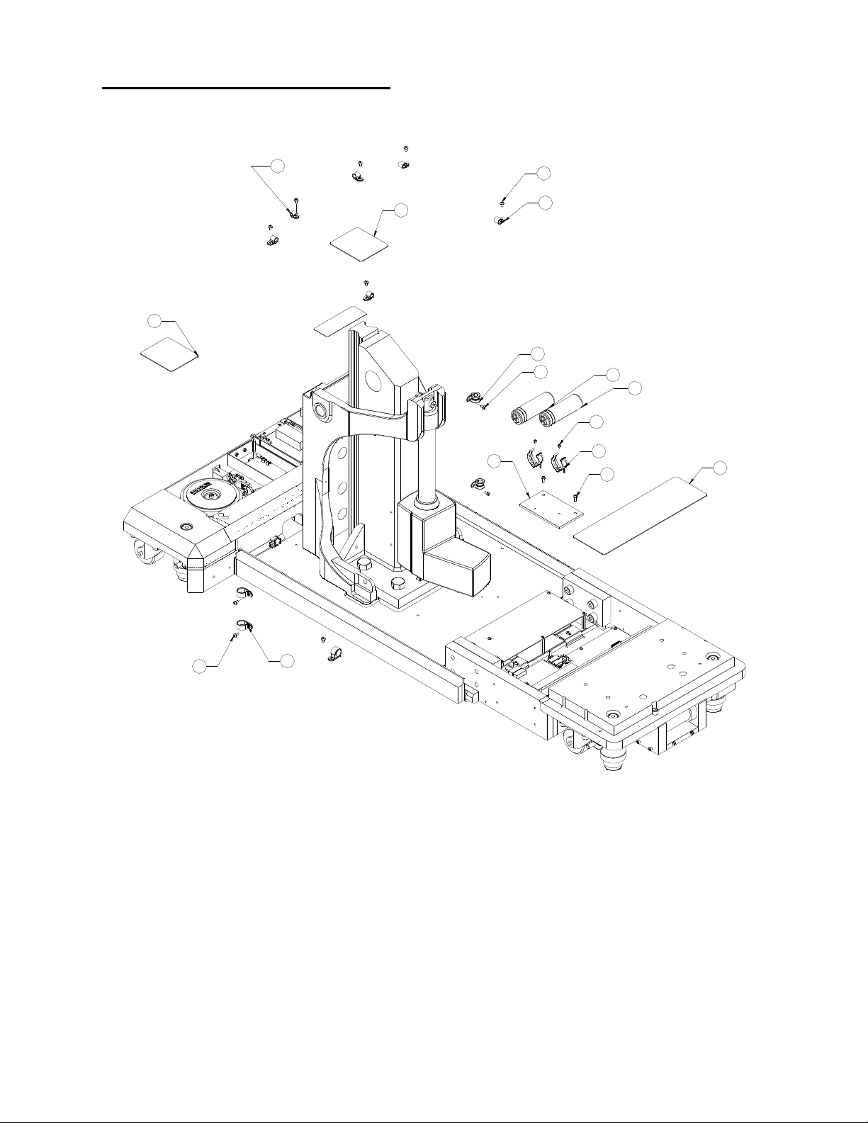
11.7 Base Assembly Exploded View
NOTE: Numbers correspond to item numbers on parts list in section 11.4.
128
107 3" X 4.5"
1073" X 4.5"
40
63 6X
54 5X
55 2X
63 2X
59 2X
125
66 2X
111
122
107 3" X 13"
633X
127 3X
MIZUHOSI 2009 NW0510 Rev. D
50
Page 51

11.8 X-Ring Assembly Exploded View
NOTE: Numbers correspond to item numbers on parts list in section 11.4.
462X
56
70
37
1134X
64
47
97
63
123
672x
55
63
54
78
27
60
30
38
45
1173X
101
99
15
14
85
17
87
13
48
76
57
28
74
79
16
MIZUHOSI 2009 NW0510 Rev. D
51
Page 52
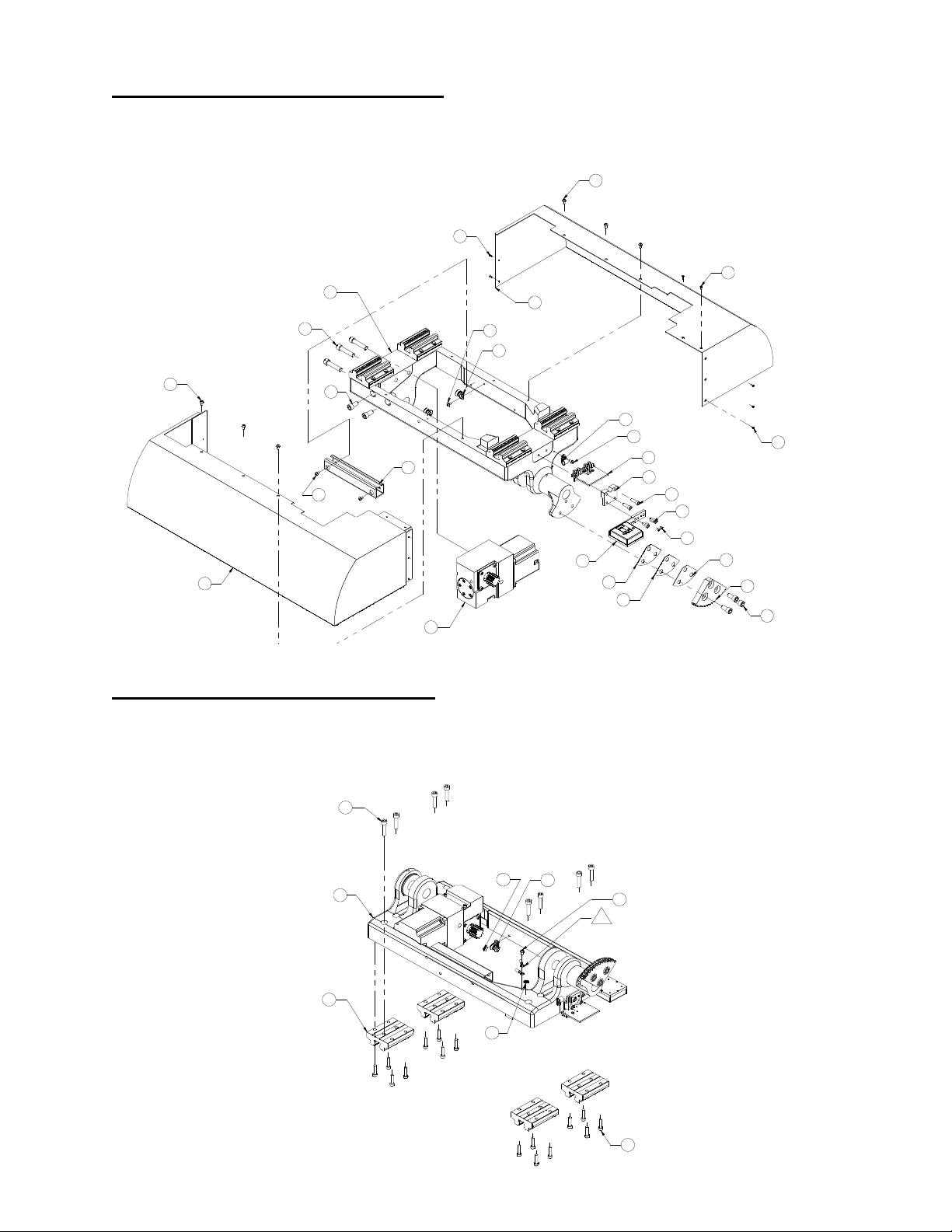
11.9 Y-Ring Assembly Exploded View
NOTE: Numbers correspond to item numbers on parts list in section 11.4.
64 3X
563X
3
843X
52
63
117
57 2X
64
51
63 2X
812X
54
63
26
41
5
34
42
77 2X
75 2X
62 2X
11
11
11.10 Y-Ring Assembly Bottom View
NOTE: Numbers correspond to item numbers on parts list in section 11.4.
968X
56 3X
10
12
80 3X
63
3
1094X
116
MIZUHOSI 2009 NW0510 Rev. D
52
117
64
4
91 16X
Page 53

11.11 X - Y Coupler Assembly Exploded View
NOTE: Numbers correspond to item numbers on parts list in section 11.4.
634X
9
4
4
105 2X
652X
116
33
55
1044X
82 2X
64 3X
54
7
103 4X
834X
MIZUHOSI 2009 NW0510 Rev. D
53
Page 54

11.12 X - Y Coupler Assembly Bottom View
NOTE: Numbers correspond to item numbers on parts list in section 11.4.
110
8
92
110
110
92
93
943X
954X
93
95 2X
93
954X
93
1172X
72
93
93
735X
93
95 4X
32
65 6X
31 2X
7
71 6X
108 4X
MIZUHOSI 2009 NW0510 Rev. D
54
Page 55

11.13 Replacement/Spare Parts List
10-Amp motor controller PCB 6800-1021
Base cover, floating 6800-129
Base cover, mid section 6800-130
Battery, 12V, 12A (2x reqd) NV0801
Column skirt, fixed, left 6800-267
Column skirt, fixed, right 6800-268
Column slider cover 6800-127
Floor lock gearbox assembly 6800-210
Floor lock motor 6800-217
Floor lock pad MZC700004B0
Floor lock pad screw MZA00006200
Floor lock manual crank 6800-230
Hand pendant 6807-3 (14-button)
Joystick 6800-280
LED (light assembly), amber 6800-208
LED (light assembly), green 6800-207
On/off power switch NV0586
Power supply tray assembly 6800-250
Power cord, right angle 9600-750
Power cord receptacle NV0585
Stepper controller/driver PCB 6800-4250
Table pad 6800-7140
Tilt sensor assembly 6800-247
X-ring cover, left 6800-262
X-ring cover, right 6800-263
MIZUHOSI 2009 NW0510 Rev. D
55
Page 56

12.0 Mizuho OSI CUSTOMER RESOURCE GROUP
12.1 Contact For Parts And Service
For detailed repair information or to order replacement parts, call the Mizuho OSI
Customer Resource Group:
1-800-777-4674
A Customer Resource Group line is available from 7AM-5PM PST, Monday through
Friday. Please leave a message after business hours.
Please state slowly your name, phone number, your facility name and city, and the
affected equipment model number.
An e-mail message may be left anytime at techsvcs@mizuhosi.com or through the
Customer Resource Group icon in our web site: www.mizuhosi.com.
12.2 Instant Support Value Package
Additional technical information and documentation is available via Mizuho OSI’s
subscription based instant support. Instant support is a web-based virtual support agent
accessible from Mizuho OSI’s web page; www.mizuhosi.com. Instant support provides
immediate and actionable answers to problems and questions on a 24/7 basis.
That Instant Support Value Package (ISVP) is a comprehensive support package
designed to enhance the hospitals internal equipment support efforts. Contact your
local Mizuho OSI sales representative for subscription information and additional details
of the program.
12.3 To Order Replacement Parts (RP)
1. If unable to identify part please telephone, fax or e-mail to Customer Resource
Group.
2. If part is known please telephone, fax or e-mail part number and description to
Customer Resource Group for price and availability.
3. To place Replacement Parts (RP) order please telephone, fax or e-mail part number,
description, price, customer number and method of shipment to Customer Resource
Group with purchase order. Indicate that order is for Replacement Parts (RP).
12.4 Returns To Mizuho OSI (RGA)
1. Identify parts to be returned.
2. Telephone, fax or e-mail part number and description of parts for return to Customer
Resource Group for Return Goods Authorization (RGA) number.
3. Return ship parts with RGA number clearly marked on outside of package.
4. Complete certificate of disinfected parts document #40204-17.
MIZUHOSI 2009 NW0510 Rev. D
56
Page 57

12.5 To Send A Part For Repair (RA)
1. If unable to identify part, please call, fax or e-mail to Customer Resource Group.
2. If part is known please telephone, fax or e-mail part number and description to
Customer Resource Group for Repair Authorization (RA) number.
3. Clean (disinfect) parts prior to shipping; complete certificate of disinfected parts
document #40204-17.
4. Ship part with RA number clearly marked on outside of package.
5. Part will be evaluated and customer will be contacted with the cost of repair.
6. After customer approval of repair cost, part will be repaired and return shipped to
customer.
12.6 EC Authorized Representative
Emergo Europe
Molenstraat 15
2513 BH The Hague
The Netherlands
Tel: (31) (0) 345-8570
Fax: (31) (0) 346-7299
MIZUHOSI 2009 NW0510 Rev. D
57
Page 58
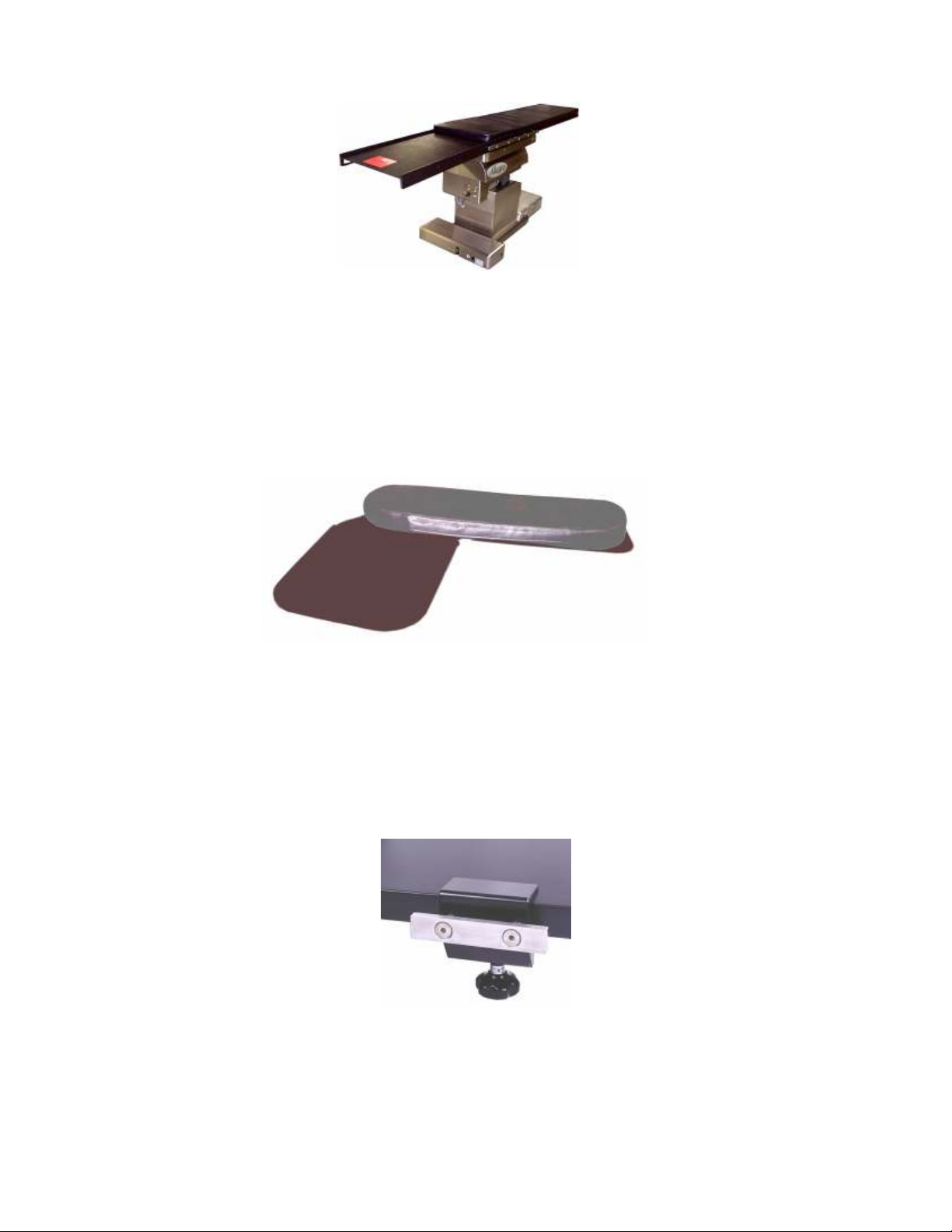
13.0 Mizuho OSI ALLEGRO™ 6800 OPTIONAL ACCESSORIES
Figure 18: Stent tray
Stent tray (Part# 6900-21)
The stent tray is designed for and intended to support guide wires, stents and catheters.
It can be mounted on either the pedestal or cantilever end of the table.
NOTE: This accessory is not designed to support a patient.
Figure 19: Radiolucent single arm board
Radiolucent single arm board (Part# 6900-12)
The radiolucent arm board is placed between the tabletop and table pad and is held in
place by the patient’s weight. This arm board has a carbon fiber surface with a 2 inch
(5cm) pad. The single arm board can be used on either side of the table, right or left.
Figure 20: Auxiliary clamp
Auxiliary clamp (Part# 6900-20)
The auxiliary clamp mounts where needed on the cantilever of the table to provide 6
inches (15 cm) of side rail.
MIZUHOSI 2009 NW0510 Rev. D
58
Page 59
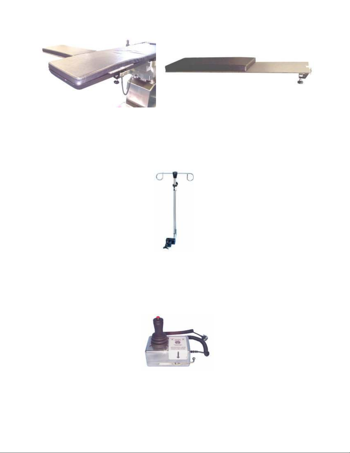
Figure 21: Radiolucent AV fistula board
Radiolucent AV fistula board (Part# 6900-25)
A radiolucent platform for performing upper extremity procedures. The radiolucent AV
fistula board has a 2 inch (5 cm) pad and attached auxiliary clamp for securing to the
table top.
Figure 22: Rail mounted I.V. pole
Rail mounted I.V. pole (Part# 6900-23)
The rail mounted I.V. pole mounts on the side rail.
It telescopes 34 – 60 inches (86 – 152 cm).
Figure 23: Joystick
Replacement Parts:
Joystick (Part# 6800-280)
See section 4.0 Basic Operation, for a complete description.
MIZUHOSI 2009 NW0510 Rev. D
59
Page 60

Figure 24: Hand pendant
Hand pendant (Part# 6807-3)
See section 4.0 Basic Operation, for a complete description
Figure 25: Swivel mount for hand pendant
Swivel mount for the hand pendant (Part# 6800-290)
The swivel mount allows for mounting the hand pendant horizontally on the side rail or
auxiliary clamp. The hand pendant then can be swiveled into the desired position for
easy access by the surgeon, anesthesiologist or surgical team.
Figure 26: Drape rod
Drape rod (Part# 6800-350)
The drape rod mounts on the side rail or auxiliary clamp and is for holding the surgical
drapes in place while the table top is being moved during a procedure.
MIZUHOSI 2009 NW0510 Rev. D
60
Page 61

Figure 27: Universal foot board with two side rail adaptors
Universal foot board (includes two side rail adaptors) (Part# 6900-51)
The universal foot board mounts on the side rail or auxiliary clamps and is designed to
provide support in maintaining the patient’s desired position in the table when the table
is placed in reverse trendelenburg.
MIZUHOSI 2009 NW0510 Rev. D
61
 Loading...