

Page 1

CONTENTS
Fig.1
Fig.2
Fig.3
Fig.4
Fig.5
General
Control
Control
Column
Valve
Fig. 6 Control
Fig.7 Power
Fig.8 Relay
Fig.9
Fig.
Fig.11
Control
10
Charging
Elevation
view
—
parts
unit - parts
unit
—
wiring
base - parts
-
exterior
box - parts
supply
board
board
(chassis) - wiring
-
relay
-
board-
limiting
arrangement
views
arrangement
arrangement
parts
parts
board
identification
identification
diagram
diagram
arrangement
arrangement
~
parts
arrangement
(1)
(2)
(3)
Operation
Adjustment
Adjustment
switches
of
of
Troubleshooting
and
adjustment
speed
various
leveling switches
and
disable
Page 2
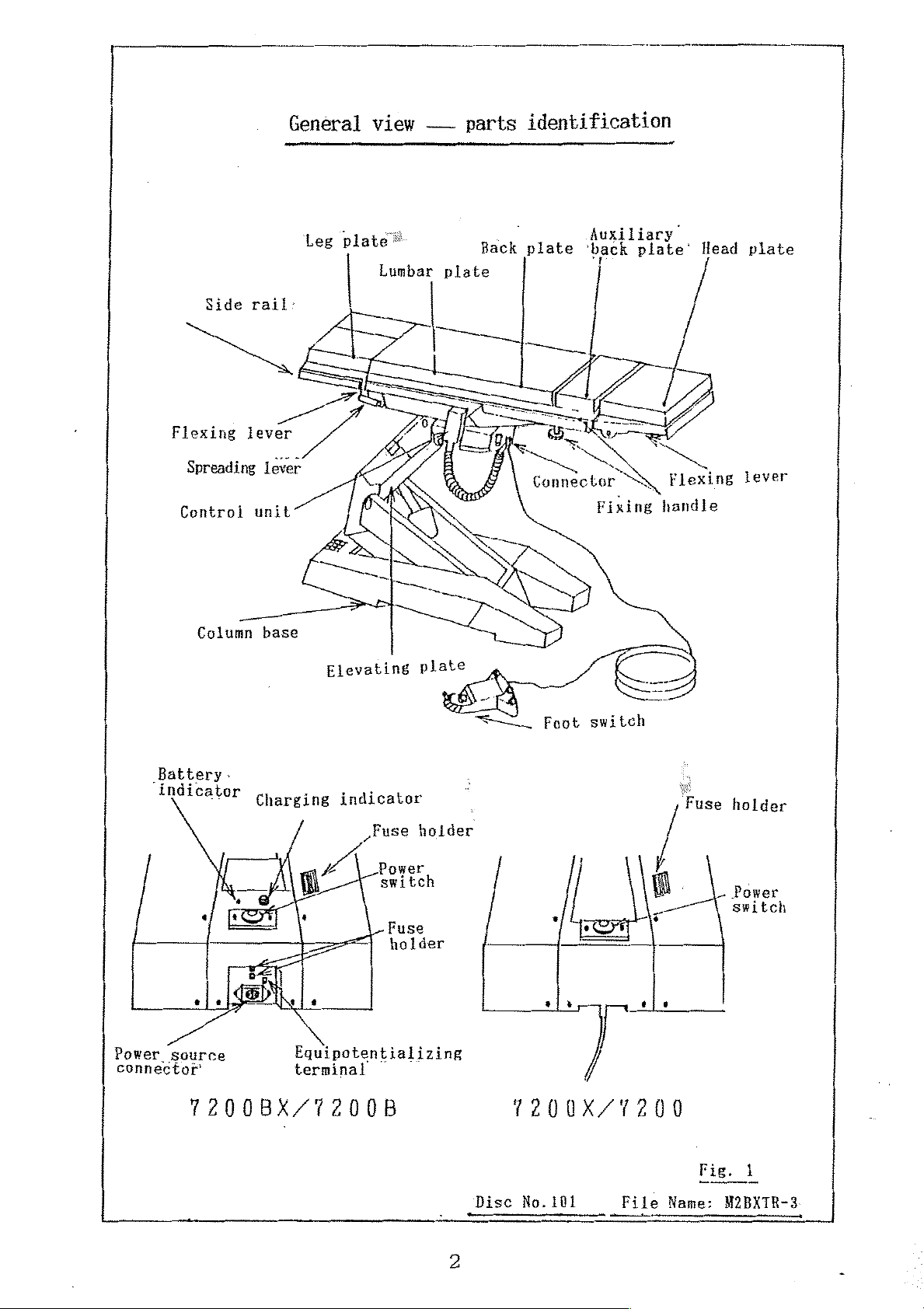
Side
Flexing
Spreading
Control
rail:
lever
lever
unit
parts
“n
Lumbar
AI
—
plate
=
—-
EA
«$
General
.
Leg
==
^
view
-
plate
E
|
>
identification
Back
plate
ak
τη
Я
ak
KORS
Connector
Auxiliary.
‘back
N
Fixing
plate’
>
M
Flexing
handle
Head
plate
lever
Battery.
‘indicator
ны
connector
Ee
Column
sie
base
Charging
e
=
SD
Elevating
indicator
„Fuse
ví
.
Equipotentializing
terminal
Power
switch
一
FuSe
holder
plate
holder
SU
~~
。
Foot
sj»
switch
*
=
/
a
を
ejo
‘Fuse
holder
Power
switch
1200BX/7200B
1200X/1200
Disc
No.
101
File
Fig.
Name:
1
M2BXTR-3
Page 3

(low
Lateral
Back
Slide
Brake
Vertical
pelvic
tilt
plate
Raise
Slide
(toward
Control
release
tilt
position)
(right
flex
(highest)
foot
down)
(up)
(left)
end)
unit - parts
pa
條
AR
E
3
EY
—
aR
7
identification
ーーーLateral
ei
————
一
,一
(high
77
一 一 Slide
一
Brake
Vertical
Back
Lower
Siide
actuation
tilt
pelvic
tilt
plate
(lowest)
(toward
(left down)
flex
(right)
-
position)
(down)
head
end)
Low
Power
MEMO
©Slide
Gn
"E"
speed
lamp
(low
appropriate
switch
selector
speed)
features
are
power
FE
available
lamp
comes
ーー
only
on
on
Model
when
7200BX/7200X.
power
ーー
Power
is
High
applied.
Leve11ing
speed
lamp
selector
(high
speed)
Disc
No.101
File
Fig.
Name:
2
M2BXTR-4
:
Page 4
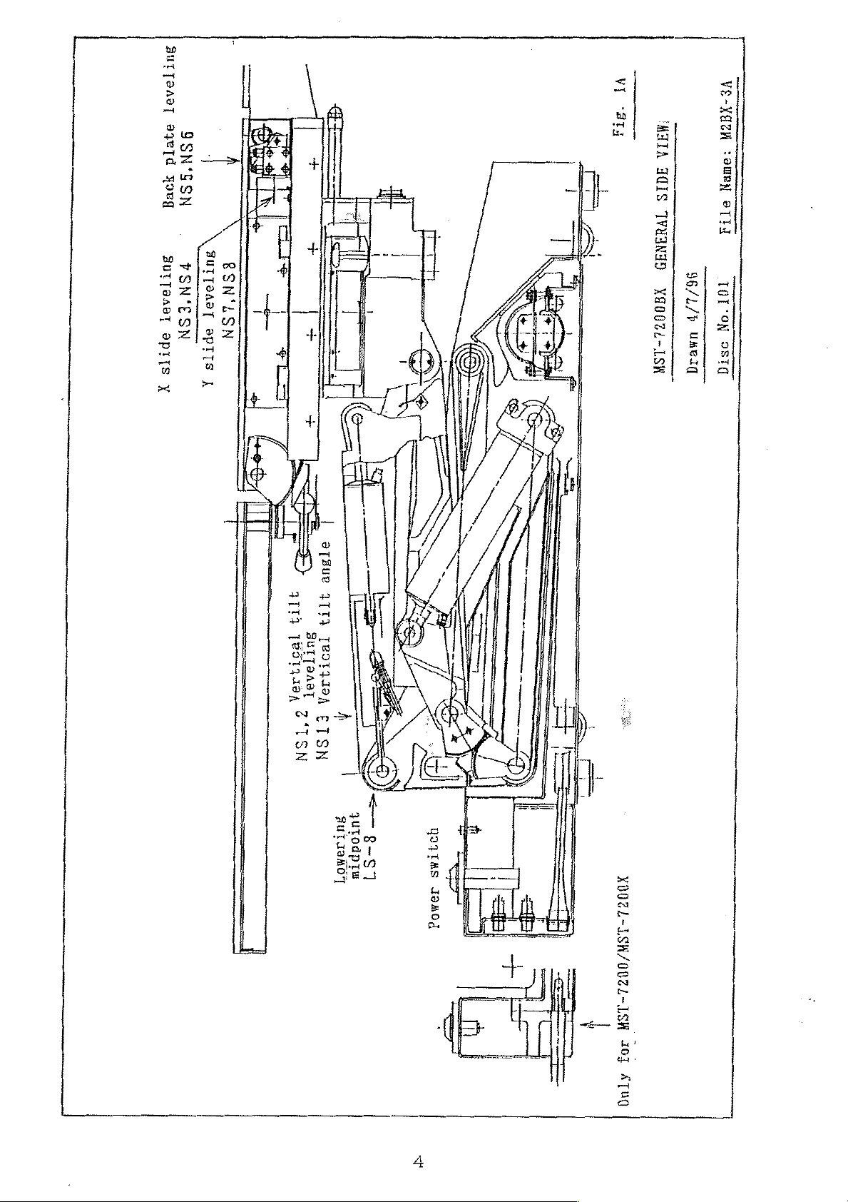
зитТелэт
эзета
SSN‘SSN
3229
.
BurTaa8T
oprrs
X
ΒΙΤΤΟΛΟΙ
PSN'ESN
8SN‘ASN
SPTTS
A
УТ
ата
VE-XATN
“META
1915
HIS
TVHINID
X90024-1SW
STTA
96/L/+
.TOT'ON
Uaeag
9STQ
aT3ue
3113
2772
3ufTaAat
18579394
12019204
?*TSN
A
ETSN
<—
qutodptw
βυταθβσΊ
8-51
UOJTAS
ABO
ay
XOOZL-LSH/OOZL-LSH
に
>“
mi
|
|
303
ATUO
Page 5
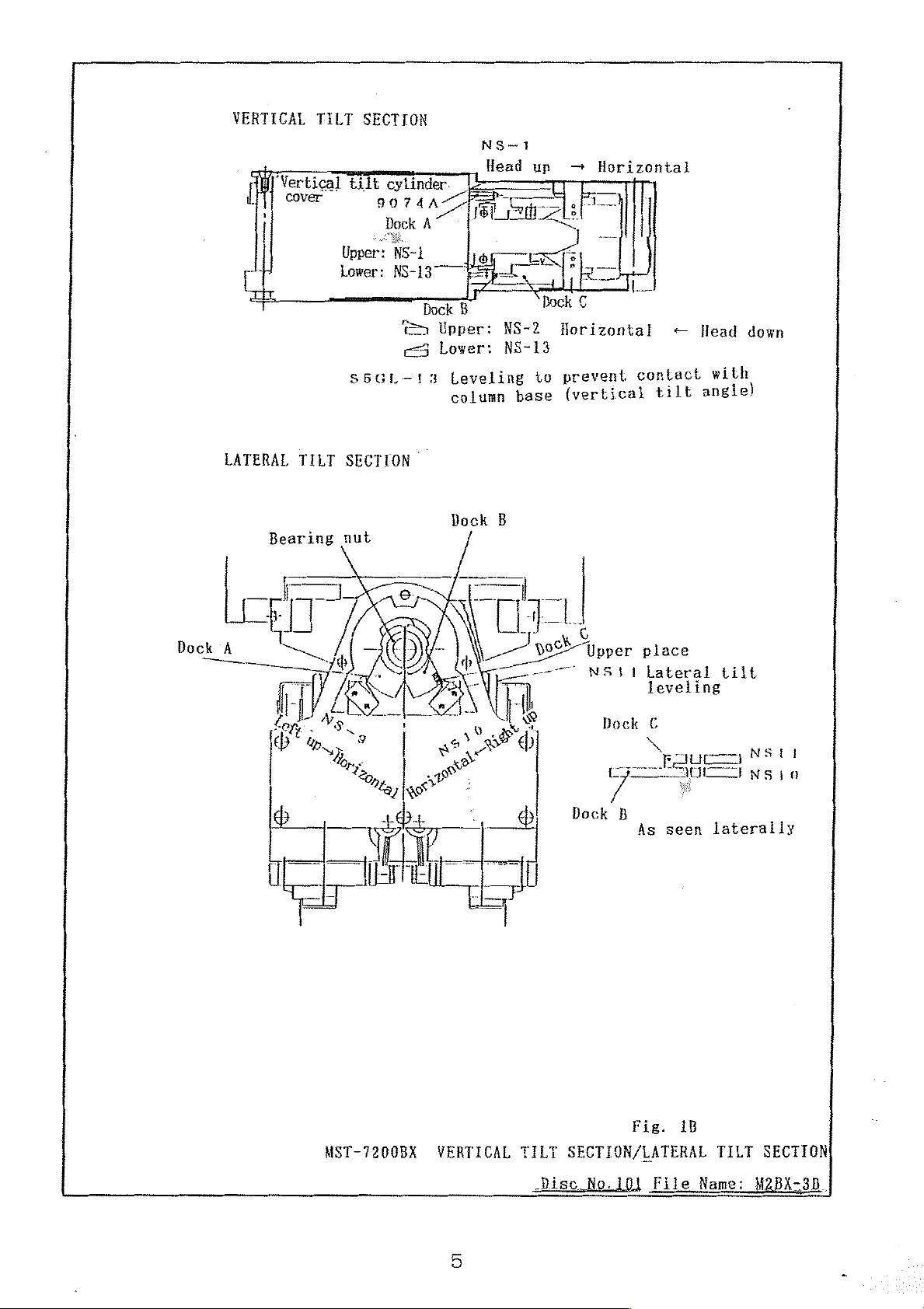
VERTICAL
Vertical
cover
LATERAL
TILT
TILT
SECTION
tilt
cylinder.
9074
Dock
Upper:
Lower:
NS-1
NS-13
©
ce3
S6GL—13
SECTION
AZ
A
Dock
Upper:
Lower:
Leveling
column
|
lie
Et
F
B
NS~1
Head
E
一
NS-2
NS-13
up
LE
一
CR
ヾ
to
base
—
Horizontal
5
|
απ.
€
Dock
Horizontal
prevent
{vertical
+
contact
tilt
Head down
with
angle)
CA
$
pai
TT
πρ
TE,
DI!
NA
o
Fi
LS
|
Mook
nos
e
—
à
Upper
NS11
Dock
lac
place
Lateral
leveling
€
As
seen
tilt
laterally
MST-7200BX
VERTICAL
TILT
Disc
Fig.
SECTION/LATERAL
No.
10]
1B
File
TILT
Name:
SECTION
МАВХ-ЗВ.
Page 6
ETTODSS\
“CT-ULYG@H
21
‘Std
.
Wop
peeH
ー
TB3U02TOH
i
_
(97809
ЧАТА
3003000
4114
12911494)
Juaaeld
:emeN
9TtJ
TOI'oN
osrG
MEIA
UOTNALXA
SN
add
ーーー
€I-SN
04
8UTT9A9T
:deaoy
E
om"
L=
eseq
ύπητου
_
96/91/p
umeıg
-
NOLIDAS
ITIL
TVOLLYIA
0022-1SH
F
Page 7

OPERATION
AND
ADJUSTMENT
In
this
gide
Upper
Lower
(1)
To
tilt,
the
and
miniature
case,
is:
place:
place:
Adjustment
change
cover
the
elevation, X sliding
on
adjust
the
High
Low
of
speed
the
an
appropriate
valve
opposite
speed
speed
right
speed
of
the
back
or
side
concerned.
lowering
raising
plate
¥Y
sliding
of
the
speed
(See
operation,
of
column
adjusting
FIGs 4 and
RE
<p-
CB
ES
the
base
|
ae
©
vertical
operating
as
seen
screw
(needle)
5.)
Black
一
mer
Pilot
Black
[Low
tilt,
table,
from
(High
(Pilot
lateral
remove
the
of
+
speed
adjustment)
speed
High
tube:
pressure
spdöd
Low
speed
operation)
speed
lowering
head
the
. .
raisins
adjustment
in
adjustment
adjustment)
high
oe
Γ
Interior:
Solenoid
coili
Page 8

(2)
Adjustment
of
various
leveling
switches
and
disable
switches
(2-1)
L5-8
LOWERING
MIDPOINT
Adjustment
2-15
GD
E
of
the
==
lowering
4-40
midpoint
The
lowering
located
the | column.
temporarily
from
vertically
Loosen
dock
LS-8
lowering
(9158)
(Z-15GD)
switch
at
the
or
the
set
LS-8
midpoint
triangle
stops
when
laterally.
sorews,
and
adjust
will
be
This
the
table
it is
rotate
pressed
switch
link
switch
tilted
so
is
on
top
the
that
when
(2-2)
Lower
position.
9163
first,
top
LS-6
Adjustment
the
so
4°
will
of
table
Then
that 9081 will
with
up,
and
be
top
adjust
the
head
the
pressed
microswitch
the
to
the
of
in
lower
the
bend
be
pressed
the
turn.
disable
lowest
of
table
the
table
floor.
switch
top
LS-6
LS
一 6
"KOGER
DISABLE
is
620mm
above
the
9163
{as
seen
for
the
from
right
side
the
head)
8
Page 9

(2-3)
Adjustment
of
the
head
up
disable
switch
LS-5
LS
HEAD
DPSABLE
Ue:
Lower
position.
of
pressed
the
microswitch
in
the
9163
first,
table
turn.
‘9183
table
Then
so
top
for
that
LS-5
the
top
adjust
9081
with
4°
will
left
to
the
the
up,
be
side
lowest
the
bend
will
head
and
pressed
be
of
the
{as
seen
from
the
head}
Page 10

(2-4)
Adjustment
of
the
back
plate
leveling switches
1527
9093
Back
Back
NS-5
up-—Horizontal
NS-6 -
down—Horizontal
5033
7520
7573
9094
Adjustment
(BACK
Loosen
Dock A and
be
plate
DOWN
the
pressed
is
ーーーーーーー
LUMBAR
Adjustment
(BACK
Loosen
UP
the
of
NS-6
~>
HORIZONTAL)
set
screw,
adjust
by
slightly
so
Dock A when
PLATE
of
NS-5
—
HORIZONTAL)
set
screw,
rotate
that
NS-6
will
the
back
up.
—SPACE:approx.
ZU
PLATE
BACK
rotate
Jam
Note:
move
If
the
difference
too
small,
like a seesaw.
soon
enough.
the
between
table
DOWN
top
will
Adjustment
—
not
Dock B and
“no
longer
the
back
HORIZONTAL
stop
in
must
be
adjust
be
plate
LUMBAR
and
the
horizontal
made
so
that
pressed
is
by
Dock B when
slightly
SPACE
Г
I
PLATE
UP — HORIZONTAL
so
that
一
-一
Back
position
it
will
NS-5
will
:approx.
一
PLATE
stop
up.
fam
is
but
1
0
Page 11

(2-5)
Centering
of X sliding
and Y sliding
Remove
below.
contact
Left
—
the
Make
with
NS3
Center
lumbar
sure
the
plate
that
cover
с
Foot
end — Center
and
the
when
take
of f Cover A shown
roller
reattaching
sliding,
X
у
of
the
Center
switch
the
— Head
in
does
cover
the
illustration
not
.
Cover
Remove
,4um
NS4
Center
end
come into
A
four
screws
—
Right
X
sliding
Loosen
right
When
centering
the
to
the
two
move
table
docks
bolts
the
top
moves
(upper
(C)
and
center
position.
like a seesaw,
and
lower)
slide
or
the X sliding
slightly
NS3
and
NS4
dock
to
pull
both
switches
the
left
of
the two
toward
or
you.
Page 12

Y
sliding
The
table
will stop
in
the
head
direction
when
NS7
switch
is
slightly
When
to
(2-6)
Dock
lowered,
the
stop
Adjustment
A
or
in
table
the
Bearing
the
top
seesaw
of
nut
foot
moves
movement
the
direction
like a seesaw,
lateral
Dock
when
tilt
B
NS8
switch
lower
leveling
Upper
NSit
is
slightly
NS7
or
switches
place
Lateral
leveling
raise
tiit
raised.
NS8
more
Adjustment
——=
of
NS-10
.
;
(RIGHT
Loosen
adjust
the
right
the
bearing
UP
the
so
—
bearing
that
NS-10
side
nut
1
HORIZONTAL)
nut a little,
will
of
the
table
securely
2
no
As
longer
top
is
after
seen
rotate
laterally
Dock B and
be
pressed
2°
up.
adjustment.
when
Tighten
Page 13

Adjustment
of
NS-9
(LEFT
UP
—
HORIZONTAL)
2
]
Adjustment
—
When
the
not
go
tilted
:
of
NS-11
oe
head
of
down
unless
laterally).
the
NS-11
Loosen
adjust
the
the
(LATERAL
When
so
table
has
the
bearing
so
that
left side
bearing
TILT
NS“10
that
top
NS-1i
is
been
down
pressed
NS-9
of
nut
LEVELING)
is
no
will
by
nut a little,
will
no
the
table
securely
longer
be
20°
(i.e.
top
pressed,
pressed.
or
more,
if
longer
is
after
the
the
rotate
be
pressed
2°
up.
adjustment.
adjust
table
table
top
Dock À and
when
Tighten
Dock C (>
top
will
remains
——
Supplementary
am
Z
Z
J
~
~
人
고
-D-
|
4mm
explanation:
ij
+
H
i
=
©
flat
A
©
head
È
screw
|
TIZI).
E
Lateral
adjustment
“the
attached
©
fully
direction
appropriate
switch.
tilt
front
Slide
leveling
of
NS-11
connector
the
table
in
the
using
and
with
panel
top
head
an
control
13
Page 14

©
Remove
the
12mm
cap
nut(Ajand
return
the
table
top
to
the
center
©
Remove
through
©
Now
(2-7)
position
There
can
should
be
removed
eight
the
Adjustment
using
be a gap
4mm
the
gap
lateral
of
the
control
downward.
flat
between
tilt
switches
the
switch.
between(©)
head
vertical
screws
Gand(®)to
can
and
be
adjusted.
tilt
È,
through
Band
pull
the
line
leveling
Remove
which
down
drawn
switches
the
the
panel}
inside.
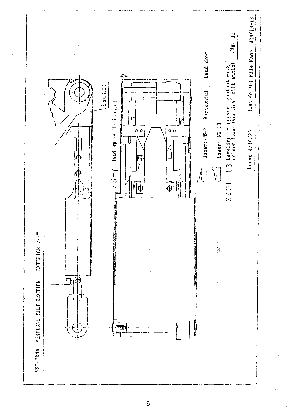
9074A
panel)
vertical
Vertical
cover
S5GL-13
tilt
00
9074 ㅅ 그를,
Upper:
Lower:
Upper:
>
<3
Lover:
Leveling
column
cylinder.
NS-1
Dock
NS-1
Head
o
EE
了
B
NS-2Horizontal—Head
NS-13
prevent
to
base
(vertical
up-
Horizontal
ok
|;
Dock
contact
tilt
€
NS — 7
=
down
with
angle)
tilt
Adjustment
Adjust
which
that
by
the
Loosen
Little
cylinder
(HEAD
UP — HORIZONTAL)
NS-1
NS-1
Dock A when
table
to
the
will
the
adjust.
of
support
is
the
top
4mm
cover.
»NS~1
mounted
be
pressed
head
is
2°
cap
bolt
Tighten
on
so
of
up.
a
Page 15

it
securely
after
adjust-
Adjustment
Adjust
place
down.
Adjustment
Adjust
Dock C when
will
of
NS-2
the
support
no
longer
of
NS-13
Dock C so
the
(HEAD
on
DOWN — HORIZONTAL)
which
be
pressed
(VERTICAL
that
NS-13
head
of
NS-2
the
is
when
TILT
in
the
table
mounted
the
head
ANGLE)
lower
top
ment.
so
of
place
is
20°
that
the
will
(See
NS-2
table
down.
FIG
in
be
12.)
the
top
is
pressed
upper
2°
by
dun
————
Dock
set
€:
X
screw
Dock
B
Loosen
Dock C by
Tighten
the
the
adjustment.
4mm
moving
set
(See
set
it
screw
FIG
screw
back
securely
12.)
and
and:
adjust
forth.
after
15
Page 16

(2-8)
If
the
the
Safety
table
column
feature
is
base
of
lowered
and
get
limiting
with
the
damaged.
the
table
To
avoid
table
top
top
positioning
tilted,
this,
it
the
might
table
and
release
hit
against
has a safety
feature
tilting
depending
Example
The
table
lowered
lateral
position.
How
to
incorporated
to
a
certain
on
positioning.
1.
stopped
with
tilt
release
the
and
the
to
limit
degree.
halfway
table
high
safety
its
when
top
pelvic
feature:
lowering,
Certain
in
the
lateral
functions
tilting
are not
and
vertical
available
The
table
cases:
1)
Activate
top
2)
Press
position.
lateral
3)
Press
can
to
the
the
be
lowered
the
vertical
the
near-horizontal
lateral
In
this
tilt
position.
leveling
to
tilt
case,
switch.
the
tilt
switch
the
lowest
and
low
position.
to
table
position
pelvic
put
the
top
1
6
in
position
table
will
either
top
not
of
to
to
the
achieve
the
following
put the
horizontal
the
maximum
table
Page 17

Caution
@
Do
on
Memo
©
The
(107
not
press
the
table
vertical
),
when
the
top.
tilt
the
leveling
and
high
table
switch
pelvic
top
position
is
above
for
this
the
purpose
will
be
floor
when a patient
achieved
by
620
up
mm
or
to
20°
less.
is
However,
pelvic
©
When
than
pelvic
lateral
position.
Example
The
the
the
20°
2
table
table
if
lateral
position
table
is
(15° ) to
position
tilt
is
stopped
is
lowered
tilt
will
in
the
the
of
less
not
operated,
halfway
be
lateral
level
with
is
not
achieved
condition,
than
X
5°
the
The
when
the
operated , the
up
to
45°
tilt
and
high
in
the
to
the
level
table
figures
can
be
in
( )
vertical
(30°
pelvic
lateral
condition,
lowered
apply
tilt
),
position
tilt
to
the
to
7200B/7200.
and
of
and
or
lowest
high
less
low
when
table
and
low
top
pelvic
in
the
vertical
position.
tilt
17
Page 18

How
to
The
table
cases:
1)
Activate
top
2)
Press
Caution
©
Do
on
Memo
release
can
to
the
not
press
the
the
be
lowered
he
vertical
the
near-horizontal
leveling
the
leveling
table
top.
safety
to
tilt
switch.
feature:
the
lowest
and
switch
position
high
pelvic
position.
for
this
in
either
position
purpose
of
the
following
to
put
the
table
when a patient
is
©
The
but
table
In
Checking
1.
Lower
1-1
maximum
this
will
top.
the
lowest
the
disable
Procedure:
1)
LS6
angle
vary
proper
should
of
the
slightly
position,
limiting
Lower
activate
vertical
depending
this
operation
the
table
tilt
feature
to
disable
and
on
top
low
pelvic
the
elevated
cannot
—
MST~7200X,
with head
lowering.
position
be
actuated.
up
position
7200BX
about
is
15°
20°
of
,
the
.
2)
At
the
same time
LS5
should
18
activate
to
disable
head
up
Page 19

1-2.
operation.
Procedure:
Lower
LS8
activates
The
vertical
20°
or
The
lateral
the
table
tilt
more).
tilt
top
until
(620mm).
angle
leveling
switch
the
lowering
NS13
switch
activates
NS11
does
midpoint
(head down
not
switch
activate
2.
Head
3.
Lateral
down
Procedure:
disable
tilt
(lateral
should
The
lateral
(lateral
The
vertical
down
Lower
down
20°
operation
disable
tilt
not
the
5°
go
down
tilt
tilt
tilt
or
more).
table
left
further.
leveling
5º
angle
top
to
should
up
left
the
or
right
switch
up or
switch
lowering
not
up)
NSI1
right
NS13
midpoint,’
activate.
and
the
does
not
up).
activates
table
activate
(head
and
head
top
Procedure:
The
vertical
dom
The
20º
lateral
activate
Lower
lateral
(lateral
the
tilt
tilt
or
less).
tilt
table
leveling
1
angle
leveling
tilt
top
9
switch
10°
to
the
should
NS13
switch
left
up
lowering
activate
activates
NS11
does
or
right
midpoint,
when
the
(head
not
up).
and
left
Page 20

4,
Lateral
tilt
up
switch
operation
or
the
right
up
switch
is
operated.
5.
Head
Procedure:
down
Procedure:
operation
Operate
Lower
the
switch
The
table
and
right
Operate
levering
Lower
switch
the
LS8
vertical
vertical
table
LS8
activates.
top
should
up
respectively.
lateral
switch
table
activates.
tilt
angle
and
top
tilt
NS11
top
switch
lateral
until
be
leveling
the
operable
activates).
until
Lower
the
the
NS13
tilt
table
leveling.
lowering
up
to
30°
(the
lateral
lowering
head
activates
midpoint
left
tilt
midpoint
until
(head
down
up
the
6.
Lowering
Procedure:
operation
Operate
20°
or
less).
position.
Check
achieved.
that
lateral
leveling
Lower
further
the
even
maximal
switch
table
after
Lower
ì
head
tilt
NS11
head
the
the
table
dom
leveling
top
(the
activates).
maximally
vertical
tilt
to
the
position
lateral
(lower
angle
lowest
can
the
switch
be
tilt
head
20
Page 21

NS13
has
activated).
The
The
The
spreading
While
horizontally.
as
flexing
pushing
they
lever
Check
position.
operation
lever
the
Release
are.
that
the
of
spreading
the
table
the leg
lever
lever,
and
top can
plate
downward,
the
be
-
leg
lowered
MST-7200
move
plates
the
to
leg
will
the
series
be
lowest
plates
fixed
While
Release
To
push
lever
pushing
the
the leg
upward.
the
lever,
plates
Only
flexing
and
upward,
push
Flexing
lever upward,
the leg
up
it
the
plates
is
lever———
not
necessary
leg
move
will
plates.
3»
the leg
be
plates
fixed
to
push
Spreading
as
they
thé
lever
downward.
are.
flexing
Page 22

The
spreading
Push
the
a
little.
lever
spreading
Release
lever
the
downward
lever,
and
and
the
spread
leg
plates
the
leg
can
plates
be
pulled
apart
up
The
to be
To
reattach
the
will
flexing
Push
Then
detached.
the leg
spreading
be
attached
lever
the
flexing
the
leg
plates,
lever
downward.
securely.
lever upward,
plates
can
align
be
the
Release
and
the
adjusted
plates
the
with
lever,
engaging
upward
the
and
rack will
or
downward
table
the
be
and
push
leg
plates
released.
manually.
22
 Loading...