

Page 1

hana
®
HIP AND KNEE ARTHROPLASTY
SURGERY TABLE
OWNERS MANUAL
Model 6875
This manual is written in five
languages in the following order:
(en) English
(es) Spanish
(fr) French
(de) German
(it) Italian
MIZUHO OSI
30031 AHERN AVENUE UNION CITY, CA 94587
Bus: 510-429-1500 Toll Free: 800-777-4674 Fax: 510-429- 85 00
WWW.MIZUHOSI.COM ·
NEWHIPNEWS.COM · NEWSPINENEWS.COM
MIZUHOSI 2009 1 NW0508 Rev. D
Page 2

TABLE OF CONTENTS
1.0 INTRODUCTION............................................................................................................................4
1.1 Important Notices ......................................................................................................................4
1.2 General Description...................................................................................................................6
1.3 Specifications ............................................................................................................................7
1.4 Shipping ....................................................................................................................................7
1.5 Storage......................................................................................................................................7
1.6 Glossary Of Terms ....................................................................................................................8
2.0 CONTROLS IDENTIFICATION...................................................................................................... 9
2.1 Table Orientation.......................................................................................................................9
2.2 Major Controls Location ............................................................................................................9
2.3 Control Panel Identification .....................................................................................................10
3.0 BASIC OPERATION ....................................................................................................................11
3.1 Control Operation ....................................................................................................................11
3.2 Caster Floor Locks ..................................................................................................................11
3.3 Moving The Table....................................................................................................................11
3.4 Hand Pendant/Control Panel Operation..................................................................................12
3.5 Leg Spars ................................................................................................................................13
4.0 INSPECTION ............................................................................................................................... 15
4.1 Acceptance And Transfer........................................................................................................15
4.2 Inspection And Transfer ........................................................................................................ 15
4.3 Pre-Procedure/Post-Procedure ...............................................................................................15
4.4 Semi-Annual............................................................................................................................15
5.0 FUNCTION CHECK ..................................................................................................................... 16
6.0 THE ELECTRICAL SYSTEM .......................................................................................................18
6.1 Description ..............................................................................................................................18
6.2 On/Off Power Switch ...............................................................................................................18
6.3 Component Circuit Breakers ...................................................................................................18
6.4 Power Cord .............................................................................................................................19
6.5 Battery System ........................................................................................................................19
6.6 Troubleshooting.......................................................................................................................20
7.0 CLEANING AND MAINTENANCE ...............................................................................................21
7.1 Cleaning And Disinfecting .......................................................................................................21
7.2 Preventative Maintenance.......................................................................................................22
8.0 SET-UP OF 6875 hana
®
SURGERY TABLE ...............................................................................23
8.1 Insertion And Removal Of Leg Spars – 6875-350 & 6875-360 ...............................................23
8.2 Removable Femur Jack Mount Assembly...............................................................................24
8.3 Attaching Femur Lift(s) And Femur Lift Foot Pedal 6875-600, 6875-601, 6875-19.................28
8.4 Femoral Hook Support And Femoral Hook(s) Sterilization Guidelines....................................29
8.5 Insertion Of Well Leg Support Adaptor 6875-200....................................................................32
8.6 Optional Patient Transfer Assembly Instructions For Use.......................................................33
8.7 Attaching hana
8.8 Knee Flexion Sterilization Guidelines......................................................................................35
8.9 IM Nailing Femur: Unilateral Skeletal Traction 6875 hana
8.10 IM Nailing Femur: Unilateral Skin Traction 6875 hana
8.11 IM Nailing Femur: Lateral Decubitus Position With Bilateral Skin Traction 6875 hana
Surgery Table Set-Up....................................................................................................................44
8.12 IM Nailing Tibia: Supine With Unilateral Skin Traction 6875 hana
8.13 Hip Pinning: Supine With Unilateral Skin Traction 6875 hana
8.14 Hip Pinning: Supine With Bilateral Skin Traction 6875 hana
8.15 Anterior Approach Total Hip Replacement 6875 hana
8.16 Total Knee Replacement 6875 hana
8.17 Total Knee Replacement 6875 hana
9.0 6875 hana
®
SURGERY TABLE COMPONENTS AND ACCESSORIES .....................................58
9.1 6875 hana
®
Knee Flexion System™ For TKA 6875-230..................................................34
®
Surgery Table Set-Up.................38
®
Surgery Table Set-Up ....................41
®
Surgery Table Set-Up...47
®
Surgery Table Set-Up .........49
®
®
®
Surgery Table Set Up................................................55
®
Surgery Table Set Up................................................57
®
Standard Components........................................................................................58
Surgery Table Set-Up ...........51
Surgery Table Set-Up ....................53
®
MIZUHOSI 2009 2 NW0508 Rev. D
Page 3

10.0 REMOVAL AND REPLACEMENT OF COMPONENTS ............................................................63
10.1 Hand Pendant Control...........................................................................................................63
10.2 Foot Pedal .............................................................................................................................63
10.3 Motion Control Module ..........................................................................................................64
10.4 Internal Batteries ...................................................................................................................65
10.5 Table Lift Assembly ...............................................................................................................67
10.6 Tilt/Trendelenburg Assembly.................................................................................................68
10.7 Femur Lift Assembly, Left/Right ............................................................................................69
10.8 Caster(s)................................................................................................................................69
11.1 Replacement/Spare Parts List...............................................................................................70
11.2 Interconnect Diagram, 100VAC, 120VAC, 230VAC..............................................................72
12.0 TROUBLESHOOTING ...............................................................................................................73
12.1 Table Malfunction ..................................................................................................................73
12.2 Diagnostics Tree ...................................................................................................................73
13.0 MIZUHO OSI CUSTOMER RESOURCE GROUP..................................................................... 76
13.1 Contact For Parts And Service..............................................................................................76
13.2 Instant Support Value Package.............................................................................................76
13.3 To Order Replacement Parts.................................................................................................76
13.4 To Return Damaged Parts ....................................................................................................76
13.5 To Send A Part For Repair....................................................................................................77
13.6 Warranty................................................................................................................................77
13.7 European Union EC Representative .....................................................................................77
MIZUHOSI 2009 3 NW0508 Rev. D
Page 4
1.0 INTRODUCTION
1.1 Important Notices
Caution:
To ensure safe operation of the equipment, please READ THESE INSTRUCTIONS
COMPLETELY and keep this manual readily available for future reference.
Carefully observe and comply with all warnings, cautions and instructions placed on the
equipment or described in this manual.
In this manual, the WARNING symbol is intended to alert the user to the presence
of important operation, maintenance, or safety instructions.
Protection Against Electrical Shock Hazard:
This symbol indicates this equipment is an applied part TYPE B in accordance with IEC
60601-1 and is generally suitable for applications involving external or internal contact with
the patient, excluding the heart. The patient circuit is connected to protective earth and this
equipment should be connected only to hospital grade AC outlets with a protective earth
ground.
This symbol indicates an external ground stud that is required for use when the AC
power cable is not connected to a protective earth ground hospital grade AC outlet in your
operating room or facility.
To protect the patient, hospital staff and the table from possible electrical hazards, an
external ground wire connection is required between the external ground stud and protective
earth ground.
WARNING:
If the integrity of the AC power source is in doubt, the equipment shall be operated
from its internal electrical power source (battery).
WARNING:
Proper preoperative and intra-operative procedures must be followed to prevent
venous stasis and pooling, pressure sore development, neuropathy, improper electro
surgical tissue grounding, hypertension and hypothermia.
NOTE: The application techniques outlined in these instructions are the manufacturer’s
suggested techniques. The final disposition of each patient’s care as related to the use of
this equipment rests with the attending physician.
This symbol indicates a Pinch Point and danger to body extremities.
MIZUHOSI 2009 4 NW0508 Rev. D
Page 5

Disposal of Electrical Components:
In accordance to the WEEE directive, all electrical components, batteries and carbon
composite components must be returned to Mizuho OSI for proper disposal. Please contact
Mizuho OSI Customer Resource Group Service Department at 1-800-777-4674 for further
information regarding this requirement.
THIS DEVICE IS TO BE USED BY TRAINED PROFESSIONAL PERSONNEL ONLY.
MIZUHOSI 2009 5 NW0508 Rev. D
Page 6
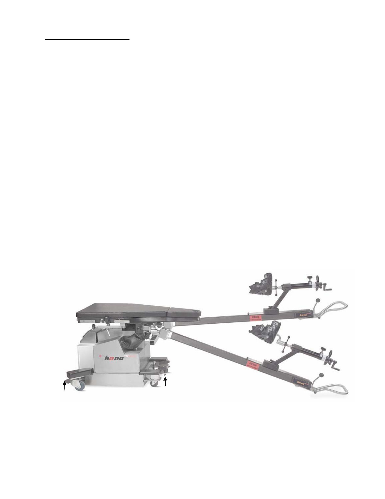
1.2 General Description
The Mizuho OSI 6875 hana® Surgery Table is designed to safely hold in proper position a
patient undergoing orthopedic surgical procedures including supine position for the anterior
approach for Total Hip Arthroplasty, Total Knee Arthroplasty, IM Nailing of the Femur or Tibia
and Hip Pinning, and Lateral position for IM Nailing of the Femur.
It is a stand-alone, single-pedestal, AC powered or internal battery powered table designed
to position a patient in a supine or lateral position during surgical procedures.
The table has a 2” (5 cm) MIZUHO OSI Tempur-Pedic® pad. The TEMPUR® used in the
manufacture of MIZUHO OSI pads has viscoelastic properties and is a temperature sensitive
material, becoming softer where the patient’s body is making the most contact with the
surface and remaining firm in areas where less body contact is being made. Pressure is
distributed evenly over the entire surface area. The pad is radiolucent, MR safe and latex
free. The benefits of using MIZUHO OSI Tempur-Pedic® are improved pressure
management, reduced shear forces and enhanced patient comfort.
The hana® Surgery Table has three primary electrically powered functions: height up/down,
left/right lateral roll and trendelenburg/reverse trendelenburg. Electromechanical actuator
motors perform these motions which are controlled by means of a hand pendant or onboard
auxiliary control panel with functions clearly labeled. The table is also equipped with
powered left and right femur lifts that are controlled by a foot pedal providing the surgeon the
ability to raise and lower the femoral hook during the anterior approach total hip arthroplasty.
Four (4) independent, manual caster floor locks are utilized to stabilize the table in the
operating location.
HEAD END
FOOT END
Manual caster floor
locks
Manual caster floor
locks
Figure 1: Mizuho OSI 6875 hana® Surgery Table, right-side view
MIZUHOSI 2009 6 NW0508 Rev. D
Page 7
1.3 Specifications
The table is designed to hold a maximum patient load of 450-pound (205 kg) in a
procedural position at any point within its physical range.
The table has a height range of 29 to 49 inches (74 cm – 124 cm).
The width of the tabletop is 21.5 inches (55 cm) and narrows to 10 inches (25 cm) toward
the foot end and 5 inches (13 cm) at the perineal post.
The length of the tabletop is 48.5 inches (123 cm). The overall length with leg spars
attached is 124 inches (315 cm).
The lateral roll range is +/- 12 degrees and the trendelenburg/reverse trendelenburg
range is +/- 12 degrees.
The leg spars rotate on a spherical joint and are capable of positioning the patients leg in
up to 20 degrees of adduction, 45 degrees of abduction, raise the leg to 28 degrees
above level and lower the leg to 35 degrees below level.
The tabletop has a radiolucent equivalency of less than 1 millimeter of aluminum.
The input power requirement is 100 VAC, 50Hz or 60Hz, 120 VAC, 60Hz or 230 VAC,
50Hz as indicated on the table label.
The table may also be operated under battery power. The expected working life of a fully
charged battery is approximately 12 hours at a 10% duty cycle.
WARNING:
This symbol indicates an external ground stud that is required for use when the
AC power cable is not connected to a protective earth ground hospital grade AC outlet
in your operating room or facility.
To protect the patient, hospital staff and the table from possible electrical hazards, an
external ground wire connection is required between the external ground stud and
protective earth ground.
1.4 Shipping
®
The 6875 hana
Surgery Table must be shipped using the appropriate shipping carton.
During shipment the table is to be kept in an environment within the following limits:
1. Ambient temperature -4 °F (-20 °C) to + 122 °F (50 °C).
2. Relative humidity from 10% to 100%, including condensation.
3. Atmospheric pressure from 50 to 110 kPa.
1.5 Storage
When not in use, the hana
®
Surgery Table should be stored in a clean, dry environment with
temperature between 32 °F (0 °C) and 120 °F (49 °C). The table cover provided should be
utilized and serves as a dust cover.
To ensure the battery is always fully charged and ready for use, the table should be stored
with the power cord inserted on the head end control panel and attached to an appropriate,
hospital grade AC outlet (100VAC, 120VAC or 230VAC) and the power switch turned on.
MIZUHOSI 2009 7 NW0508 Rev. D
Page 8

1.6 Glossary Of Terms
This glossary of terms assumes the patient is supine with their head at the head end of table
(toward control panel) and their feet at the foot end of table (toward leg spars). The hand
pendant functions are oriented for this position only.
AUXILIARY CONTROL PANEL is a panel of buttons and lights located on the back of the
pedestal.
FOOT END OF TABLE refers to the leg spar control end of the table.
HEAD END OF TABLE refers to the end of the table where the power cord, on/off power
switch, and auxiliary control panel are located; otherwise referred to as the pedestal end.
HOSPITAL GRADE AC OUTLET refers to specially designated outlets (receptacles) that
include additional grounding reliability, assembly integrity, strength and durability. Hospital
Grade is indicated by a Green Colored Dot on the face of the outlet.
LEFT SIDE OF THE TABLE refers to the side to the patient’s left in the supine position.
This also corresponds to the hand pendant button labeled left lateral roll.
LOWER THE TABLE refers to lowering the height of the table. This corresponds to the hand
pendant button labeled height down.
PEDESTAL refers to the main column structure that supports the tabletop.
RAISE THE TABLE refers to raising the height of the table. This corresponds to the hand
pendant button labeled height up.
RETURN TO LEVEL, OR LEVEL THE TABLE, refers to returning the tabletop to a state of
level regardless of its position. This corresponds to the hand pendant button labeled return to
level. Holding the return to level button longer than approximately three seconds will also
lower the tabletop to its lowest position.
REVERSE TRENDELENBURG refers to raising the height of the head end of the table tilting.
This corresponds to the hand pendant button labeled rev.tren.
RIGHT SIDE OF THE TABLE refers to the side to the patient’s right in the supine position.
This also corresponds to the hand pendant button labeled right lateral roll.
TRENDELENBURG refers to lowering the height of the head end of the table. This
corresponds to the hand pendant button is labeled tren.
MIZUHOSI 2009 8 NW0508 Rev. D
Page 9
2.0 CONTROLS IDENTIFICATION
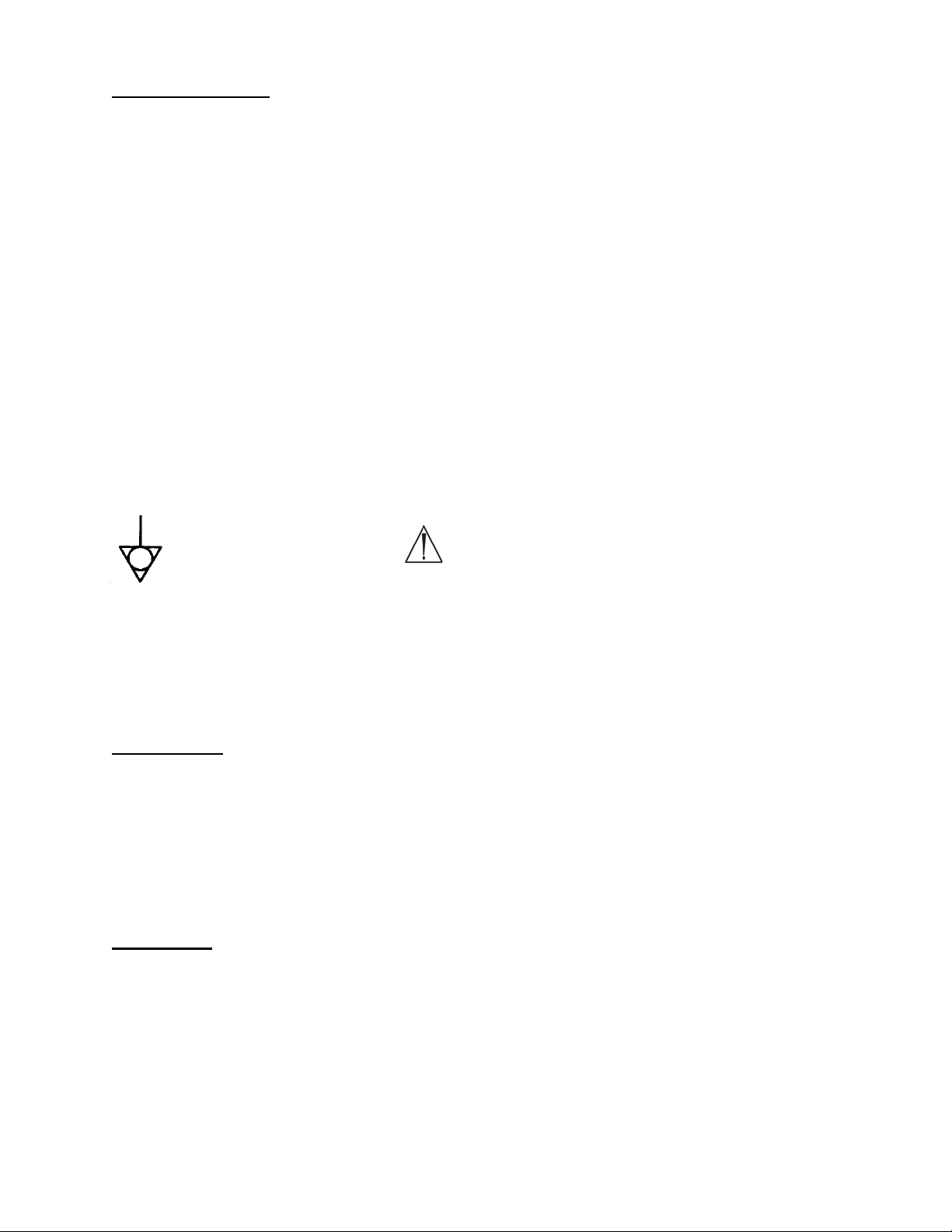
2.1 Table Orientation
The major components of the 6875 hana® Surgery Table are identified below. The table is
described as having a head end and a foot end. The control panel, on/off switch and the
power cord receptacle are located at the head end of the table.
HEAD END
FOOT END
Figure 2: Right-side view with patient in supine position
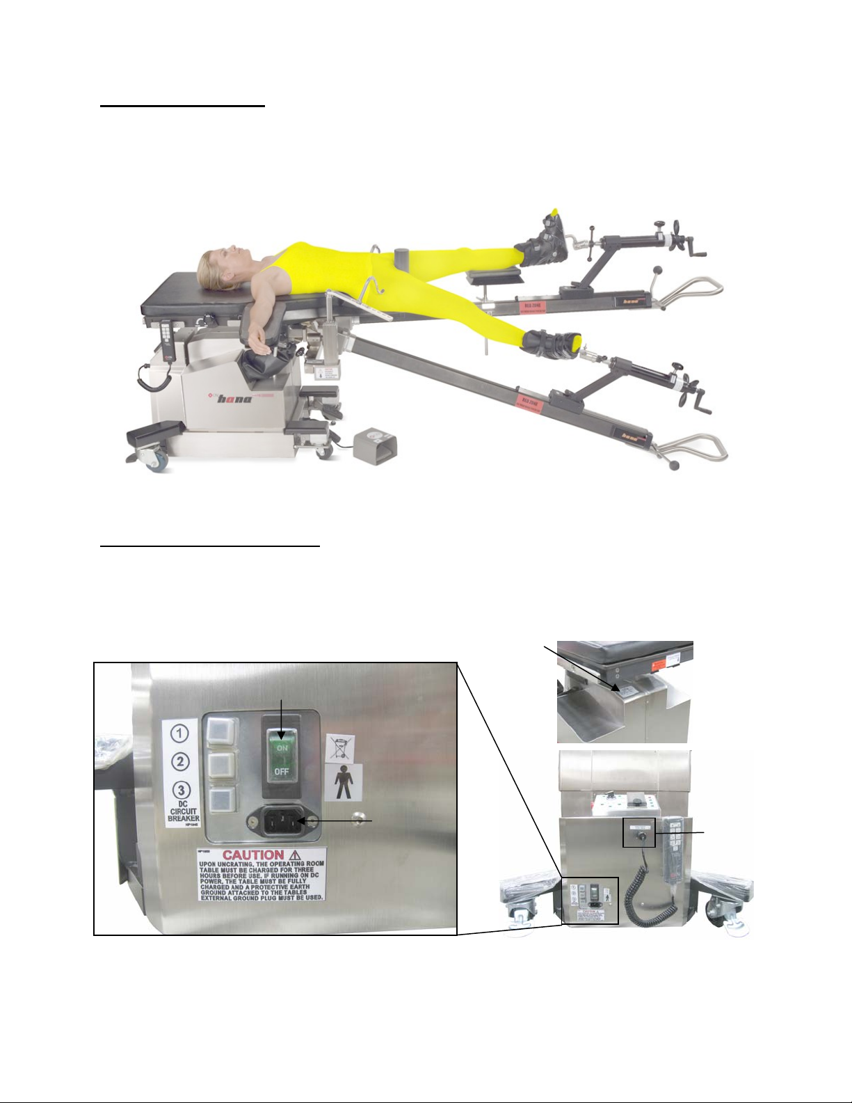
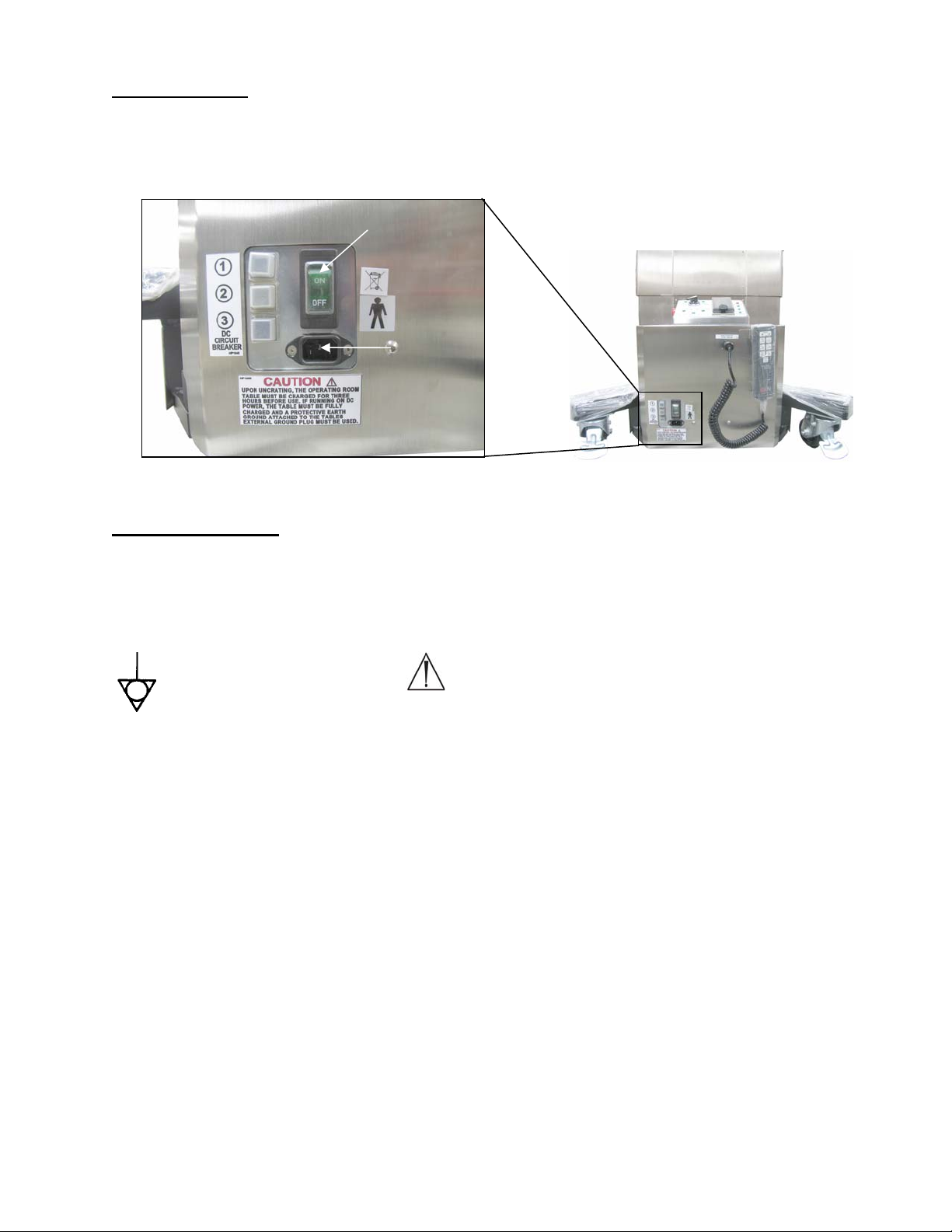
2.2 Major Controls Location
The control panel, on/off power switch, power cord receptacle and model number/serial
number identification label are located at the base of the head end of the table.
On/off power
switch
Number/serial
model
Power cord
receptacle
Hand
pendant
Figure 3: Head end power supply box and control panel
MIZUHOSI 2009 9 NW0508 Rev. D
Page 10

2.3 Control Panel Identification
The control panel is divided into 3 sections:
Section 1: Femur lift control section. Selection switch changes between right and left femur
lift operation. Indicator displays status of femur lift connection (left, right). Indicator displays
status of foot pedal connection. (Indicator illuminated: Parts are connected, Indicator not
illuminated: Parts not connected)
Section 2: Control pad section. The control pad and the hand pendant control table
up/down, lateral tilt and trendelenburg; see section 3.4 for operation of the hand pendant and
control pad.
Section 3: Power indicator section. LED indicators notify user of the following conditions
when illuminated:
1. Battery condition
a. BATTERY CHARGE: Battery power low or no battery installed.
b. BATTERY OK: Battery has sufficient power to operate table
c. AC POWER: Indicates table is running on line (100, 120, 230 VAC) power from
wall receptacle.
d. BATTERY POWER: Indicates table is running from internal battery power.
Femur lift
control
1
section
Control pad
2
section
Figure 4: Control panel
Release
button
Power
indicator
3
section
MIZUHOSI 2009 10 NW0508 Rev. D
Page 11

3.0 BASIC OPERATION
3.1 Control Operation
Refer to the model/serial number label on the head end of the table for input voltage
requirements. Plug the power cord into the power cord receptacle, located at the head end
of the table and into a properly grounded receptacle. Turn on the on/off power switch. The
green light in the power switch illuminates, indicating that AC power is applied to the table.
This switch functions as a combination on/off power switch, circuit breaker and pilot light.
NOTE: A startup self-diagnostic routine is initiated each time the table is plugged in and
turned on.
3.2 Caster Floor Locks
Prior to transferring a patient onto the table and at all times when the table is in use, ensure
all four (4) independent, manual caster floor locks are in the locked position. To engage the
caster lock, step on the foot pad and depress to the floor. To unlock, slide foot under pad
and lift to disengage lock.
LOCK
Figure 5: Floor lock in the unlocked position Figure 6: Floor lock in the locked position
Location of external
ground stud
UNLOCK
®
NOTE: The casters and locks installed on your hana
Surgery Table may look different than
those depicted above but they will operate in the same manner that is described.
3.3 Moving The Table
After all four (4) floor locks are unlocked, the table can be rolled for relocation. It is best that
the table be rolled with the foot end pointed in the direction of travel. The 6875 hana®
Surgery Table is heavy and a minimum of two people should move it, one at the head end,
one at the foot end, and care should be taken to control it when rolling.
WARNING:
If the table is allowed to roll too fast, it may be difficult to stop or turn. Impact of the
table top with a stationary object may cause serious damage to the table top. If an
impact occurs the table must be visually inspected for visible damage, and a Function
Check must be performed (see section 5.0 of this manual). If damage is discovered or
the table does not pass the Function Check call your Mizuho OSI service
representative.
MIZUHOSI 2009 11 NW0508 Rev. D
Page 12

3.4 Hand Pendant/Control Panel Operation
The 6875 hana® Surgery Table is controlled by means of a hand pendant, alternate control,
via control panel built into power supply. The hand pendant is plugged into the receptacle
labeled hand pendant on the control panel (see figure 3). To activate a desired function,
press and hold the appropriate button on the hand pendant until the desired position is
achieved.
The hand pendant is equipped with a return to level button. This button functions to first level
the lateral roll, second level the trendelenburg, third re-level lateral roll and fourth brings the
table to its lowest position. A delay of 3 seconds is programmed after the leveling functions
are completed before returning to its lowest position. To achieve the final position, this
button must be held continuously until motion stops. The controller considers the table to be
level if it is within +/- 2 degrees of horizontal. If the return to level button is pressed while the
table is within this range, it may not move. If it is required to adjust the table to a position
closer to zero degrees, press the appropriate function button on the hand pendant until the
desired position is achieved.
Height Up
Trendelenburg
Left Lateral Roll
Figure 7: hana
Height Down
Reverse
Trendelenburg
Right Lateral Roll
®
Surgery Table 6807-4 hand pendant
Height Up
Trendelenburg
Left Lateral Roll
Height Down
Reverse
Trendelenburg
Right Lateral
Roll
Figure 8: Head end control panel
WARNING:
When installing a hand pendant, turn the power switch off, then plug in hand pendant
connector and rotate locking collar clockwise until hand tight. To operate any of the
desired functions, turn the power switch on and wait for 20 seconds for the table to
power up and run its self diagnostics.
MIZUHOSI 2009 12 NW0508 Rev. D
Page 13

3.5 Leg Spars
The 6875 hana® Surgery Table is equipped with two adjustable leg spars. Each leg spar is
designed to support the foot in the traction boot and allow for traction, abduction, adduction,
raising or lowering of the leg. When the leg is in a desired position, the spar can be locked to
maintain that position. A dial is provided to gauge the degree of internal and external rotation
and should be zeroed out and locked in place utilizing the thumb screw when the foot is in
the neutral position. Gross and fine traction are also controlled near the foot end of the spar.
Rotation lock
Foot rotation
Fine traction
Spar lock
handle
Internal/external
rotation dial
Gross
traction
Figure 9: 6875 Spar controls
To unlock the spar for abduction, adduction or height adjustment, hold the spar with one
hand by the loop handle and move the spar lock handle (knobbed lever) from the locked to
unlocked position (refer to picture below). When you have positioned the leg where needed,
lock the spar by rotating the spar lock handle clockwise to the locked position. If the spar will
not hold position, rotate lock handle further toward the locked position. The spar should be
held securely by the looped handle at all times when it is not locked.
Figure 10: Spar ball joint lock/unlock loop handle of leg spar
Unlock
Lock
Loop handle
WARNING:
Failure to lock the spar lock handle can cause the spar to drop when not held in place.
WARNING:
Leg spars can be damaged if allowed to contact the floor during table operation. Clear
area of any obstructions or obstacles during table movement.
MIZUHOSI 2009 13 NW0508 Rev. D
Page 14

Figure 11: 6875 hana® Surgery Table with leg spars attached & set up for bilateral anterior approach total hip
replacement
MIZUHOSI 2009 14 NW0508 Rev. D
Page 15

4.0 INSPECTION
4.1 Acceptance And Transfer
1. Upon receipt of your Mizuho OSI 6875 hana® Surgery Table, remove it from the shipping
carton by following the provided instructions. Remove any protective wrapping or
packaging. Visually inspect all surfaces for freight damage. Check each caster for proper
rolling operation.
NOTE: Any freight damage must be reported to the freight carrier immediately upon delivery.
It is the responsibility of the recipient to make freight damage claims.
2. Read the model/serial number identification label found at the head end of the table to
confirm the serial number and the input power requirements.
3. Place the 6875 hana® Surgery Table in an area with at least 4 feet of clearance on all
sides.
4. Perform Function Check; see section 5.0.
4.2 Inspection And Transfer
Before use, inspect the device for possible damage, excessive wear or non-functioning parts.
Visually inspect all accessible areas, electrical cords and all movable parts for possible
damage that may adversely affect the proper operation of the hana® Surgical Table.
Damaged or defective products should not be used or processed. Contact your local Mizuho
OSI sales representative for repair or replacement.
4.3 Pre-Procedure/Post-Procedure
Inspect and test the table as described in Function Check section 5.0.
Thoroughly clean the table as described in the Cleaning and Maintenance section 7.0.
Pay special attention to the cleanliness of the controls as excessive soil can affect
function.
Inspect the power cord for cuts in the insulation or damage to the connector.
On a smooth surface with the caster locks engaged, push the table. The table should not
move.
4.4 Semi-Annual
It is recommended to perform a Preventative Maintenance (PM) check on your 6875 hana
®
Surgery Table (see section 7.0 Cleaning and Maintenance).
A PM checklist is available from Mizuho OSI Customer Resource Group (800-777-4674).
MIZUHOSI 2009 15 NW0508 Rev. D
Page 16

5.0 FUNCTION CHECK
Perform all steps in this procedure before using the table. For a complete definition of terms
used in this procedure, please refer to the Glossary of Terms in section 1.6 of the manual.
1. Turn the power switch off. Plug in the hand pendant cable connector into the hand
pendant receptacle on the control panel.
2. If the table is to be used under battery power, put the power switch in the on position and
wait for 20 seconds for the table to power up and run its self diagnostics. The battery
power lamp on the control panel should illuminate.
WARNING:
This symbol indicates an external ground stud that is required for use when the
AC power cable is not connected to a protective earth ground hospital grade AC outlet
in your operating room or facility.
To protect the patient, hospital staff and the table from possible electrical hazards, an
external ground wire connection is required between the external ground stud and
protective earth ground.
3. Battery operation check:
3.1 Observe table battery power status light in the power indicator section of the control
panel or on the hand pendant. A green light indicates the table is set for battery
power operation.
3.1.1 If green battery Ok light is on, the table is ready to operate normally.
3.1.2 If red battery charge light is on, the battery must be charged prior to using the
table. To charge the battery, make sure the power cord is plugged into a live
receptacle and turn on the power switch. This switch will illuminate indicating
that appropriate power is applied to the table. The table must remain plugged in
and switched on for a minimum of 3 hours to insure sufficient charging of the
battery to operate the table.
3.1.3 If red check battery light remains on after 3 hours, continue to charge battery for
up to 18 hours.
3.1.4 If green battery ok light does not illuminate after 18 hours, refer to section 6.5 of
this manual.
NOTE: The table may be used with AC power even if the battery status light is red, indicating
batteries need charging.
4. If the table is to be used under line power, plug power cord into an appropriate hospital
grade AC outlet and turn on the power switch. Note that the power switch illuminates
indicating the AC power on. The AC power lamps on the control panel and hand pendant
should illuminate.
5. Hand pendant check:
5.1 Press and hold HEIGHT UP button. Observe that the tabletop moves up.
5.2 Press and hold HEIGHT DOWN button. Observe that the tabletop moves down.
5.3 Press and hold REVERSE.TRENDELENBURG button. Foot end of tabletop becomes
lower than the head end
MIZUHOSI 2009 16 NW0508 Rev. D
Page 17

5.4 Press and hold TRENDELENBURG button. Head end of tabletop becomes lower
than the foot end
5.5 Press and hold LEFT LATERAL ROLL button. Observe that the tabletop tilts to the
left.
5.6 Press and hold RIGHT LATERAL ROLL button. Observe that the tabletop tilts to the
right.
5.7 Move tabletop out of level in both tilt and trendelenburg by 5 degrees and raise table
at least 2 inches from lowest position. Press and hold RETURN TO LEVEL button.
The tabletop first levels roll and trendelenburg and then after a three-second delay,
the tabletop moves down to its lowest height position. Observe that the table top is
level and in its lowest height position.
6. Control panel check:
6.1 Repeat steps 5.1 through 5.7 using the control panel buttons.
7. Femur lift control and foot pedal check:
7.1 With femur lift connected with electrical connectivity, the corresponding light on the
control panel should illuminate indicating a good connection. See section 8.3 for
proper installation of femur lift and foot pedal.
7.2 With femur lifts and foot pedal connected and connectivity indicator lights green,
position the control knob located in section 1 of the control panel (see figure 4) to
either the left femur lift or right femur lift. Test femur lift foot pedal function for
operation of the indicated femur lift. Repeat for opposite side.
MIZUHOSI 2009 17 NW0508 Rev. D
Page 18

6.0 THE ELECTRICAL SYSTEM
6.1 Description
The electrical system provides control of all table functions and is comprised of a power cord,
an on/off circuit-breaker switch, wire harnesses, a power supply, a controller circuit, a hand
pendant, floor lock jackscrew-actuators, and various electromechanical actuators. Electric
motor-driven lead-screw actuators manipulate the table height, lateral roll and trendelenburg
functions. The input power requirement is 100 VAC 50/60Hz, 4 Amp, 120 VAC 60Hz, 4 Amp
or 230 VAC 50Hz, 2 Amp, 10%/6 minute duty cycle as indicated on the serial number label.
Refer to 6875 hana® Surgery Table Electrical Interconnect Diagram in section 11.2 for details
of the electrical system.
The primary components of the electrical control system are contained in the power supply
box at the head end of the table.
6.2 On/Off Power Switch
An illuminated on/off power switch and circuit breaker is located on the head end of the table.
When illuminated, it indicates that the table is plugged into a live electrical Hospital Grade AC
outlet and the power is on. (When the table is turned on using battery power, this switch will
not illuminate). This switch also serves as a circuit breaker. In the event of an overload
condition this switch will trip off. To reset, push to the off position and then the on position.
6.3 Component Circuit Breakers
The electrical system includes individual component 24-VDC circuit breakers located at the
head end of the table. If a short circuit occurs in the low voltage circuit, the breaker will trip
as indicated by a button protruding from the access hole. To reset, press the button in and
release.
WARNING:
Determine the source of the overload prior to resetting this switch. If unable to
determine and fix the source of failure, contact Mizuho OSI for additional support.
MIZUHOSI 2009 18 NW0508 Rev. D
Page 19
6.4 Power Cord
The table is equipped with a detachable standard IEC power cord connector. The power cord
is connected to the table at the IEC power entry socket located below the on/off switch, at the
head end control panel.
On/off power
switch
Power
cord
receptacle
Figure 12: Head end power supply box and control panel
6.5 Battery System
The 6875 hana® Surgery Table is equipped with a battery system that provides power to all
functions, and consists of two batteries (NV0801). Due to the relatively low power
consumption of the 6875 hana® Surgery Table, the table can be used on battery power for up
to 12 hours at 10% duty cycle.
WARNING:
This symbol indicates an external ground stud that is required for use when the
AC power cable is not connected to a protective earth ground hospital grade AC outlet
in your operating room or facility.
To protect the patient, hospital staff and the table from possible electrical hazards, an
external ground wire connection is required between the external ground stud and
protective earth ground.
Battery charge status is shown via a LED on the hand pendant labeled battery status and in
the power indicator section of the control panel.
On the hand pendant:
If illuminated green = OK.
If illuminated red = charge required
If a recharge is required, charging the batteries is necessary for a minimum of 3 hours. Fully
discharged batteries will require 18 hours for a complete charge. To charge the batteries,
simply plug the power cord into an appropriate hospital grade AC outlet and turn the power
switch on. It is important to plug in the table as soon as possible after the battery status LED
is illuminated red.
MIZUHOSI 2009 19 NW0508 Rev. D
Page 20

WARNING:
Life of the batteries can be shortened if the table remains unplugged and turned on for
extended period of time with the red battery charge light illuminated. While in storage
it is desirable that the table be plugged in and the power switch turned on so that the
batteries remain charged. If this is not possible, the batteries must be charged for at
least three hours per week under normal use conditions. This can be accomplished
when using the table under AC power since the system batteries are automatically
charged while the table is plugged in and turned on.
Both batteries should be replaced every five (5) years or when they fail to hold a charge.
6.6 Troubleshooting
In the event of a table malfunction:
Check input power, verify the power cord is plugged into a live hospital grade AC
electrical outlet.
Verify the power switch is on; the switch illuminates green.
Check hand pendant is plugged in and lights illuminated.
Switch main power to off, wait 30 seconds and turn to on position.
Contact Mizuho OSI Customer Resource Group if table function is not restored, please
note what functions are working as well as those not working when you call (see section
13.0 of this manual for more information on Customer Resource Group).
MIZUHOSI 2009 20 NW0508 Rev. D
Page 21

7.0 CLEANING AND MAINTENANCE
7.1 Cleaning And Disinfecting
NOTE: Never pour any liquid directly onto the table. Never subject the 6875 hana® Surgery
Table to an equipment washing machine.
Use of iodophors will cause staining.
Table exterior:
The exterior surface should be regularly wiped clean with a mild detergent solution and
wiped dry with a soft lint-free cloth. This includes the table pad and table top.
Care should be taken to avoid exposing the table to excessive moisture. Flooding, fogging
or steam cleaning is not recommended.
Blood or other fluids, etc., if allowed to remain on the table for a long period of time, will
require special cleaning to remove. A 5% acetic acid solution or white vinegar and water
solution is especially good for this purpose.
Clean with a good commercial cleaning compound, such as Stainless Steel Magic or Acme
White Finish, and then buff the surface by hand to correct staining and discoloration of plated
or stainless steel surfaces only.
To disinfect exterior surfaces, use a quaternary ammonium compound or similar type
disinfectant compound according to manufacturer's directions for use. Wipe dry with a soft
lint-free cloth.
NOTE: Failure to thoroughly dry the surface after cleaning and disinfecting may result in
rust.
Table Pad:
®
MIZUHO OSI
Tempur-med® Pad
IMPORTANT: The MIZUHO OSI Tempur-Pedic
®
pad should always be stored in a flat
position. It can actually get stiff in cold temperatures and can crack and
break if in a rolled position. It is important that you allow the pad to warm to
room temperature before attempting to utilize or handle it.
When handling always grasp by the entire thickness of the pad.
Do not lift, slide or carry MIZUHO OSI Tempur-med
®
pads by grabbing the fabric. The cover
may tear or rip.
The pad is intended to be cleaned in place. It does not need to be rotated or flipped.
Clean with standard hospital disinfectants labeled for use on table pads. Always dilute and
rinse per manufacturer’s label instructions. Wipe dry with a lint free cloth. Do not soak or
MIZUHOSI 2009 21 NW0508 Rev. D
Page 22

autoclave pads. The continued use of bleach or highly concentrated chemicals will void the
warranty on the cover.
When cleaning the bottom of the pad or the table top, simply lift one end of the pad, and fold
it over onto the other end. Clean the pad or the table top then return to pad to flat on the
table top.
7.2 Preventative Maintenance
Routine table care will assure many years of trouble-free service.
Lubrication:
All components are lubricated for life at the factory and no other lubrication for the table is
required.
Preventative Maintenance:
Contact OSI Technical Service for a complete preventative maintenance checklist.
For detailed repair information or to order replacement parts, call or contact via the web the
OSI technical services department:
1-800-777-4674 Extension 2
techsvcs@mizuhosi.com
www.mizuhosi.com
Technical services is available from 7am – 5pm PST Monday – Friday. Please leave a
message at the extension after normal business hours.
MIZUHOSI 2009 22 NW0508 Rev. D
Page 23

8.0 SET-UP OF 6875 hana® SURGERY TABLE
Instructions are provided for the following components to the 6875 hana® Surgery Table:
Leg spars 6875-350
Femur lift(s) and foot pedal assembly 6875-600, 6875-601, 6875-19
Femoral support and femoral hook(s) 6850-110.6850-919, 6850-918
Well leg support adaptor 6875-201
hana® Knee Flexion System™ for TKA 6875-230
8.1 Insertion And Removal Of Leg Spars – 6875-350 & 6875-360
Raise the height of the table to be able to easily access the spar mount. Insure the spar
locking knob is in the unlocked position by turning counterclockwise. Prior to mounting the
spar, ensure the spar ball joint handle is in the locked position. One person needs to support
the distal (foot) end of the spar holding the loop handle, while another person supports the
spar as it slides into the spar mount on the table. Slide the end of the spar forward until it is
fully engaged, and a defined click should be heard when spar post is inserted past the safety
latch. Lock in place by turning the spar locking knob clockwise until tight. Slight movement
of spar up and down while tightening knob will insure a tighter lock. While continuing to
support the distal (foot) end of the spar holding the loop handle, move the spar lock handle to
the unlocked position. Reposition the spar as needed and then return the spar ball joint
handle to the locked position.
Spar mount
Spar
Figure 13: Mounting the leg spar
Spar locking knob
Unlock
Lock
Safety latch
Figure 14: Locking and unlocking the leg spar
To remove the spar from the table, one person should support the distal (foot) end of the
spar with the loop handle and one person should turn the spar locking knob counterclockwise
MIZUHOSI 2009 23 NW0508 Rev. D
Page 24
to unlock the spar. Release the safety latch by lifting it to allow the spar to be removed.
Slide the spar out of the spar mount.
8.2 Removable Femur Jack Mount Assembly
WARNING:
To ensure safe operation of the equipment, READ THESE INSTRUCTIONS
COMPLETELY and keep this instruction sheet readily available to operating room
personnel for future reference. Carefully observe and comply with all warnings,
cautions and instructions placed on the equipment or described in this manual.
Before use, inspect the device for possible damage, excessive wear or non-functioning parts.
Visually inspect all accessible areas, electrical cords and all movable parts for possible
damage that may adversely affect the proper operation of the hana® Surgical Table.
Damaged or defective products should not be used or processed. Contact your local Mizuho
OSI sales representative for repair or replacement.
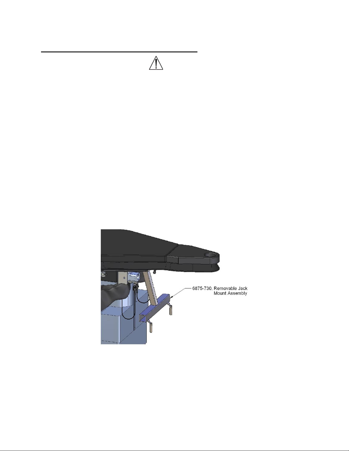
The 6875-730, removable jack mount assembly is designed to allow for removal and
reinstallation as needed depending on the type of surgical procedures being performed.
Removing the removable jack mount allows for C-arm access during hip arthroscopy and
certain fracture procedures. If C-arm access and certain fracture procedures are not
required, the removable jack mount may remain on the table.
The removable jack mount is located directly underneath the foot end of the hana® Surgical
Table top between the removable leg spars (figure 20).
Figure 15: Spars are not shown for clarification purposes
MIZUHOSI 2009 24 NW0508 Rev. D
Page 25
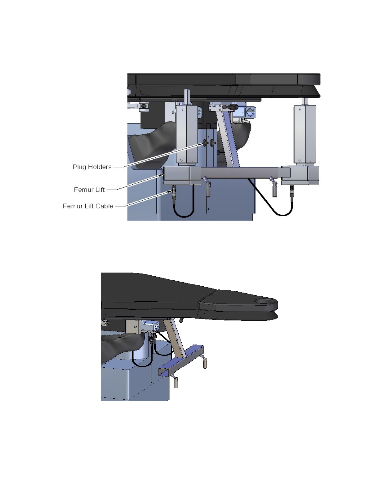
Removal:
Step 1: Unplug both femur lift cables and click the plugs into its holders (figure 16).
Step 2: Remove both femur lifts from the removable jack mount (figure 17).
Figure 16: Locking and unlocking the removable jack mount
NOTE: Steps 1 and 2 must be completed before moving to step 3 (figure 18).
Figure 17: Locking and unlocking the removable jack mount
MIZUHOSI 2009 25 NW0508 Rev. D
Page 26

Step 3: Locate and loosen the ratchet black lever handle by rotating it counter-clockwise until
loose (figure 18). The ratchet black lever handle operates by rotating it within its full range of
motion, depressing the center button, pulling the lever back the opposite direction then
releasing the button and rotating it within its full range of motion once again.
Figure 18: Locking and unlocking the removable jack mount
Step 4: Push the silver lock lever up towards the table top (figures 18 & 19)
Figure 19: Locking and unlocking the removable jack mount
While holding the silver lock handle, slide the entire bracket assembly to the left until the
dove tail disengages (figure 20).
MIZUHOSI 2009 26 NW0508 Rev. D
Page 27
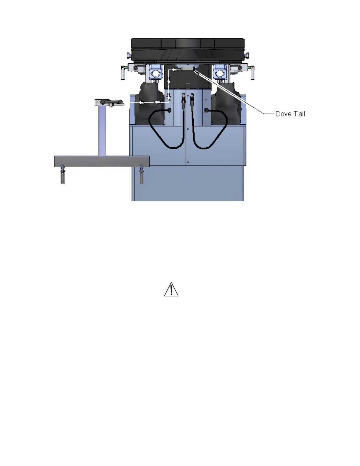
Figure 20: Locking and unlocking the removable jack mount
Installation:
To reinstall the removable jack mount, place the assembly to the left of the attachment point,
align the dove tail then slide the assembly from left to right until the silver lock lever drops
into place (figure 18). Tighten the ratchet black lever handle by clockwise rotation until fully
tightened. Do not attempt to reinstall the removable jack mount with the femur lifts attached.
WARNING:
Before every use, visually inspect that the silver lock lever is fully engaged by noting
the handle is pointing downwards and the ratchet black lever handle is tight (figure
18). Failure to perform these actions can result in the removable jack mount falling off
while the table is being tilted and cause injury to the patient.
MIZUHOSI 2009 27 NW0508 Rev. D
Page 28

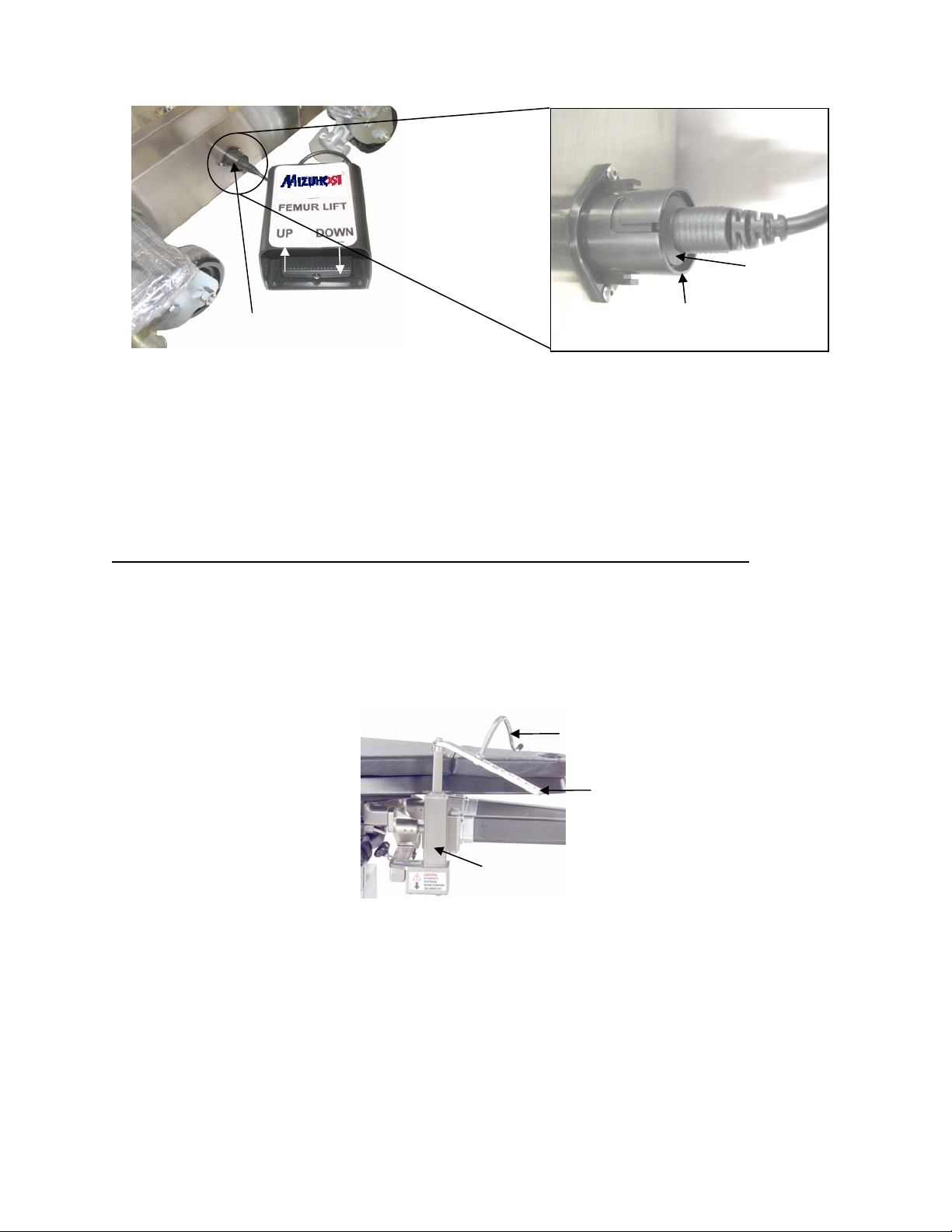
8.3 Attaching Femur Lift(s) And Femur Lift Foot Pedal 6875-600, 6875-601, 6875-19
A single foot pedal is used to operate both left and right femur lifts. Switching operation from
one to the other is accomplished by rotating the femur lift control on the control panel in the
desired direction (see figure 4).
Attach the right or left femur lift to the corresponding mounting bracket by sliding into the
bracket and secure by turning the locking knob clockwise until hand tight.
Pull down and
then pull
connector out
of socket
Locking
knob
Power cord
connector
Figure 21: Removing the power cord connector
Attach the power cord connector extending from the mounting bracket to the port on the
bottom of the femur lift. Align the red dot on the power cord connector with the red dot on the
receptacle, and it will snap in place when properly aligned.
To remove power connector, pull down on the metal checkered jacket of connector.
WARNING:
Failure to properly disconnect connector can damage device.
MIZUHOSI 2009 28 NW0508 Rev. D
Page 29
Plug the foot pedal into the port at the foot end of the table base. (The flange should be flush
or below surface of receptacle).
Flange
Foot pedal
port
Figure 22: Plugging in the foot pedal
Below this
surface
Ensure the foot pedal and femur lift function correctly. On the control panel, (see figure 4)
verify the femur lift is connected by the corresponding LED illuminating when the appropriate
lift is selected. Depress the foot pedal, up side and observe the lift rise to its fullest height
and then depress down side and observe the lift lower to its lowest position. Complete this
process for both the right and left femur lifts.
8.4 Femoral Hook Support And Femoral Hook(s) Sterilization Guidelines
The femoral hook(s) (6850-919, 6850-918) and femoral hook support (6850-110) are
designed for use with only the Mizuho OSI 6850 PROfx® Orthopedic Surgery Table or the
Mizuho OSI 6875 hana® Surgery Table. They are utilized during the Single Incision Tissue
Sparing (SITS) Anterior Approach Total Hip Arthroplasty. The hooks are imprinted with an L
and R to designate left and right.
6850-918/919 Femoral
hook
6850-110 Hook
support
Lift
Figure 23: The femur lift is in place for use with the femoral hook support 6850-110
Proper cleaning, handling and sterilization will ensure that the femoral hook(s) and femoral
hook support perform as intended.
MIZUHOSI 2009 29 NW0508 Rev. D
Page 30

How supplied:
Mizuho OSI's femoral hook(s) and femoral hook support are supplied non-sterile. Cleaning
and sterilizing of the instrument(s) is required before each use according to your hospital’s
washing, decontamination and sterilization procedures.
Contraindications:
The use of these surgical instruments is contraindicated when, in the judgment of the
physician, their use would be contrary to the best interest of the patient.
Precautions:
The Mizuho OSI's femoral hook(s) and femoral hook support are surgical instruments that
require special handling to prevent damage. Misuse can cause excessive stress or strain
that can result in damage that can adversely affect their intended use. Use caution during
cleaning and sterilization. The femoral hook(s) are approved for use only in combination with
the femoral hook support in conjunction with the Mizuho OSI 6850 PROfx® Table or Mizuho
OSI 6875 hana® Surgery Table .
Care and handling: Inspection
Before each use, inspect the femoral hook(s) and femoral hook support for damage, wear
and functionality (check for nicks, burrs or bent parts).
Damaged or nonfunctioning instruments should not be used or processed. Contact your local
Mizuho OSI sales representative or Mizuho OSI Customer Resource Group for repair or
replacement.
WARNING:
Use of damaged instruments may increase the risk of tissue trauma, infection and
length of operative procedures.
Cleaning, disinfection, preparation for sterilization:
Prior to each patient use inspect, clean, disinfect and sterilize the femoral hook(s) and
femoral hook support per hospital protocol for reprocessing surgical instruments.
Do not use steel wool, wire brushes, pipe cleaners or abrasive detergents. Use of
anything other than high quality brushes designed for surgical instrument cleaning may
result in damage.
Disassembly of the femoral hook support before cleaning is generally not necessary
unless severely soiled or dictated by hospital policy.
Do not use high acid (pH 4 or lower) or high alkaline (pH 10 or higher) products for
disinfectants, such as bleach and bi-chloride of mercury.
MIZUHOSI 2009 30 NW0508 Rev. D
Page 31

Sterilization:
NOTE: Mizuho OSI does not recommend the 6850-919, 6850-918 femoral hooks, left & right
or 6850-110 femoral hook support to be sterilized by flash or chemical sterilization.
Sterilization of the femoral hook(s) and femoral hook support is accomplished by steam. To
achieve a sterility assurance level of 10-6, Mizuho OSI recommends the sterilization
parameters listed below:
Sterilization Method Temperature Containment Type
Minimum Exposure
Time Range
Gravity Steam 270°F/134°C Wrapped 10-25 Minutes
NOTE: Other sterilization cycles may also be suitable. However, individuals or hospitals not
using the recommended methods are advised to validate any alternative methods using
current good laboratory practices (cGLP).
Storage:
1. Store the Mizuho OSI femoral hook(s) and femoral hook support with care to prevent
damage.
2. Keep stored instruments on carts or shelving in a storage area free of dust, insects,
chemical vapors and extreme changes in temperature and humidity.
Maintenance and repair of femoral hooks and femoral hook support:
WARNING:
Instruments returned to Mizuho OSI for repair require a certificate of disinfection
which testifies that each instrument has been thoroughly cleaned and disinfected.
Failure to supply a certificate of cleaning and disinfection will result in a cleaning
charge and delayed processing of your instrument repair.
1. Repair of the femoral hook(s) and femoral support hook by parties other than Mizuho OSI
will void the above warranty.
2. If the device requires repair or maintenance contact your local Mizuho OSI sales
representative or Mizuho OSI Customer Resource Group for repair or replacement.
Utilization:
Prior to the anterior approach total hip arthroplasty procedure, the appropriate right or left
femoral hook (6850-919 or 6850-918) and femoral hook support should be cleaned,
disinfected and sterilized according to the hospital’s recommended guidelines. During the
surgical procedure, the surgeon will drape the femur lift and place the sterile, femoral hook
support and sterile, femoral hook in the desired position. The height of the femoral hook
support is raised and lowered by depressing the foot pedal.
MIZUHOSI 2009 31 NW0508 Rev. D
Page 32

8.5 Insertion Of Well Leg Support Adaptor 6875-200
The well leg support adaptor attaches to the spar mount and works in conjunction with the
articulating bracket, 6300-92, and well leg support, 5855-838, for positioning the nonoperative leg. Align end of well leg support adaptor with the appropriate spar mount on table
(left or right). Slide forward until fully engaged and lock in place.
6875-200 Well leg support adaptor
Figure 24: 6875-200 Well leg support adaptor locked in place
5855-838 Well leg
support
Figure 25: Well leg support mounted on hana
®
MIZUHOSI 2009 32 NW0508 Rev. D
Page 33

8.6 Optional Patient Transfer Assembly Instructions For Use
Figure 26: Patient transfer assembly
The optional 6875-742, patient transfer assembly is intended for use while placing a patient
®
on a hana
Surgery Table. The torso of the patient should be placed on the main table top of
the hana® Surgery Table and the leg is to rest on the 6875-742, patient transfer assembly
before the foot is put into the boot.
WARNING:
The transfer board is designed only to safely support 60 lb. Placing the entire weight
of the patient on the transfer board will cause a failure of this product and could result
in injury to the patient or healthcare worker.
Setup:
The patient transfer accessory will clamp on either (left or right) spar. Clamp the device to the
side of the table from which the patient will be transferred to the table. Using the long handle
on the double bar clamp adjust the transfer board to best support only the leg or legs of the
patient. Secure the board in the desired orientation by tightening the handle (clock wise
rotation).
Use:
Transfer the patient to the table and rest the torso of the patient on the table top in a stable
position prior to lowering the leg or legs onto the transfer board. Lower the patient’s leg to
the transfer board and place the foot or feet into the boots. After properly adjusting the
boots place the hook on the boot in the holder on the traction device in accordance with this
owners manual.
Remove the transfer board from the table when not using it to transfer a patient.
Clean exterior surfaces with a mild detergent solution and wipe dry with a soft lint-free cloth.
MIZUHOSI 2009 33 NW0508 Rev. D
Page 34

8.7 Attaching hana® Knee Flexion System™ For TKA 6875-230
The hana® Knee Flexion System™ is designed to mount on the operative leg spar to support
and position the leg as needed during Total Knee Arthroplasty (TKA). It allows for full
flexion/extension of the leg and knee as well as internal/external rotation and planter/dorsal
flexion of the foot.
This device is intended to be used above the drapes in the sterile field.
Mizuho OSI's Knee Flexion System™ are supplied non-sterile. Cleaning and sterilizing of the
instrument(s) are required before each use according to your hospital’s washing,
decontamination and sterilization procedures.
Figure 27: 6875 hana® Knee Flexion System™ (6875-230) attachment detail, spar un-draped
Clamp knob
Fine traction
upright
Figure 27: 6875 hana® Knee Flexion System™ (6875-230) attachment detail, spar un-draped
Gross traction
adjustment
NOTE: Prior to draping, the fine traction must be adjusted fully towards the foot end of the
leg spar by rotating the traction handle clockwise until it stops.
Figure 28: 6875 hana® Hip and Knee Arthroplasty Table set up for right TKA spar draped
Prior to use, drape the operative side leg spar prior to attachment of the sterile Knee Flexion
System™ device. Maintaining sterile technique, position the distal end base onto the post
above the gross traction adjustment with the clamp around the fine traction upright and
tighten screw knob until secure (refer to figure 27).
MIZUHOSI 2009 34 NW0508 Rev. D
Page 35

Figure 29: 6875 hana® Knee Flexion System™ (6875-230) attachment detail spar draped
8.8 Knee Flexion Sterilization Guidelines
The knee flexion (6875-230) are designed for use with only the Mizuho OSI 6875 hana®
Surgery Table. They are utilized during the total knee arthroplasty.
Clamp knob
Fine traction
upright
Figure 30: Knee Flexion System™
Gross traction
adjustment
Proper cleaning, handling and sterilization will ensure that the Knee Flexion System
™
performs as intended.
How supplied:
Mizuho OSI's knee flexion are supplied non-sterile. Cleaning and sterilizing of the
instrument(s) are required before each use according to your hospital’s washing,
decontamination and sterilization procedures.
Contraindications:
The use of these surgical instruments is contraindicated when, in the judgment of the
physician, their use would be contrary to the best interest of the patient.
MIZUHOSI 2009 35 NW0508 Rev. D
Page 36

Precautions:
The Mizuho OSI's knee flexion are surgical instruments that require special handling to
prevent damage. Do not apply excessive stress or strain at the joints; misuse will result in
damage. Use caution during cleaning and sterilization. The knee flexion are approved for use
®
only in combination with the Mizuho OSI 6875 hana
Surgery Table.
Care and handling: Inspection
Before each use, inspect the knee flexion for damage, wear and functionality (check for
nicks, burrs or bent parts).
Damaged or nonfunctioning instruments should not be used or processed. Contact your local
Mizuho OSI sales representative or Mizuho OSI Customer Resource Group for repair or
replacement.
WARNING:
Use of damaged instruments may increase the risk of tissue trauma, infection and
length of operative procedures.
Cleaning, disinfection, preparation for sterilization:
Prior to each patient use inspect, clean, disinfect and sterilize the knee flexion and per
hospital protocol for reprocessing surgical instruments.
Do not use steel wool, wire brushes, pipe cleaners or abrasive detergents. Use of anything
other than high quality brushes designed for surgical instrument cleaning may result in
damage.
Disassembly of the knee flexion support before cleaning is generally not necessary unless
severely soiled or dictated by hospital policy.
Do not use high acid (pH 4 or lower) or high alkaline (pH 10 or higher) products for
disinfectants, such as bleach and bi-chloride of mercury.
Sterilization:
NOTE: Mizuho OSI does not recommend the knee flexion to be sterilized by flash or
chemical sterilization.
MIZUHOSI 2009 36 NW0508 Rev. D
Page 37

Sterilization of the knee flexion is accomplished by steam. To achieve a sterility assurance
level of 10-6, Mizuho OSI recommends the sterilization parameters listed below:
Sterilization Method Temperature Containment Type
Minimum Exposure
Time Range
Gravity Steam 270°F/134°C Wrapped 10-25 Minutes
NOTE: Other sterilization cycles may also be suitable. However, individuals or hospitals not
using the recommended methods are advised to validate any alternative methods using
Current Good Laboratory Practices (cGLP).
Storage:
1. Store the Mizuho OSI knee flexion with care to prevent damage.
2. Keep stored instruments on carts or shelving in a storage area free of dust, insects,
chemical vapors and extreme changes in temperature and humidity.
MIZUHOSI 2009 37 NW0508 Rev. D
Page 38

8.9 IM Nailing Femur: Unilateral Skeletal Traction 6875 hana® Surgery Table Set-Up
Figure 31: Patient positioned for Right IM Nailing Femur supine with skeletal traction and well leg retained in
traction boot
Instructions provided are for suggested set-ups. Final determination of patient positioning
and set-up is at the discretion of the surgeon and surgical team.
1. Ensure all (4) caster floor locks are in the locked position.
2. Attach radiolucent leg spars (6875-360) right & (6875-350) left to the table and lock in
place. Refer to section 8.1.
3. Place pelvic pad (6875-7129) onto table. Attach lower leg support (6850-170) to nonoperative leg spar with accessory clamp (5855-61) and lock in place.
4. Attach optional patient transfer board (6875-742) by clamping the device to the leg
spar on the side of the table from which the patient will be transferred to the table.
Refer to section 8.6.
5. Adjust table height to appropriate position to transfer patient from patient stretcher.
6. Attach appropriate traction boot (6850-485) small, or (6850-486) large to patients’
non-operative foot while on patient stretcher.
7. Transfer patient to the table in supine position, insert well padded perineal post (6850-
413), move the patient to establish firm contact with the perineal post, and secure with
patient safety strap (5840-44).
8. Place non-operative leg traction boot into traction mount on the non-operative leg
spar.
9. Install arm board with pad (6875-292) to each side of the table and position patient’s
arms out to the side or attach arm board with pad (6875-292) to the non operative side
of the table and optional cross arm support (5857) using clark socket (5393) to the
non-operative side of the table and secure the patient’s arms.
10. Attach a pin holder (not provided) to the traction mount on the operative leg spar using
the traction device hook (6850-114) and traction hook extension (6875-399). Position
the patient’s leg.
11. Remove patient transfer assembly (6875-742) by unclamping it from the leg spar and
sliding it out from underneath the fully positioned patient.
MIZUHOSI 2009 38 NW0508 Rev. D
Page 39

12. Trial position the C-arm unit on the non-operative side.
13. Install the head end drape rod assembly (6875-474) at the head end of the table and
the foot end drape rod assembly (6875-750) on the appropriate leg spar at the foot
end of the table with hole on the outside. Adjust to the appropriate height and lock.
MIZUHOSI 2009 39 NW0508 Rev. D
Page 40

Table set up for Right IM Nailing Femur supine with skeletal traction and well leg retained in traction boot
Radiolucent leg spars (2)
Right: 6875-360
Left: 6875-350
Pelvic pad
6875-7129
Lower leg support
6850-170
Accessory clamp
5855-61
Patient transfer board
6875-742
Traction boot (pair)
Large: 6850-486
Small: 6850-485
Perineal post and pad
6850-413
Patient safety strap
5840-44
Arm boards with pad (2)
6875-292
Cross arm support
5857
Clark socket
5393
Traction device hook
6850-114
Traction hook extender
6875-399
Head end drape rod
assembly
6875-747
Foot end drape rod
assembly
6875-750
MIZUHOSI 2009 40 NW0508 Rev. D
Page 41

8.10 IM Nailing Femur: Unilateral Skin Traction 6875 hana® Surgery Table Set-Up
Figure 32: Patient positioned for a right IM Nailing Femur supine with unilateral skin traction and well leg
supported in leg holder
Instructions provided are for suggested set-ups. Final determination of patient positioning
and set-up is at the discretion of the surgeon and surgical team.
1. Ensure all (4) caster floor locks are in the locked position.
2. Attach appropriate radiolucent leg spar (6875-360) right or (6875-350) left to the table
on the operative side and lock in place. Refer to section 8.1.
3. Place pelvic pad (6875-7129) onto table.
4. Attach optional patient transfer board (6875-742) by clamping the device to the leg
spar on the side of the table from which the patient will be transferred to the table.
Refer to section 8.6.
5. Slide the patient safety strap (5840-44) into place.
6. Adjust table height to appropriate position to transfer patient from patient stretcher.
7. Attach appropriate traction boot (6850-485) small, or (6850-486) large to patient’s
operative foot while on the patient stretcher.
8. Transfer patient to the table in supine position, place boot into traction mount on leg
spar, insert well padded perineal post (6850-413) move the patient to establish firm
contact with the perineal post and secure with patient safety strap (5840-44).
9. Attach well leg support adaptor (6875-200) refer to section 8.5 into the leg spar mount
on the non-operative side of the table and lock into position.
10. Attach well leg holder (5855-838) to the well leg support arm (6850-280) using
articulating bracket (6300-92) and secure patients leg.
11. Install arm boards with pad (6875-292) to each side of the table and position patient’s
arms out to the side, or attach arm boards with pad (6875-292) to the non operative
side of the table and optional cross arm support (5857) using clark socket (5393) to
the non-operative side of the table and secure the patients arms.
MIZUHOSI 2009 41 NW0508 Rev. D
Page 42

12. Remove patient transfer board (6875-742) by unclamping it from the leg spar and
sliding it out from underneath the fully positioned patient.
13. Trial-position the C-arm unit on non-operative side.
14. Install the head end drape rod assembly (6875-747) at the head end of the table and
the foot end drape rod assembly (6875-750) on the appropriate leg spar at the foot
end of the table with hole on the outside. Adjust to the appropriate height and lock.
MIZUHOSI 2009 42 NW0508 Rev. D
Page 43

Table set up for a right IM Nailing Femur supine with unilateral skin traction and well leg supported in leg holder
Radiolucent leg spars (2)
Right: 6875-360
Left: 6875-350
Pelvic pad
6875-7129
Patient transfer board
6875-742
Patient safety strap
5840-44
Traction boot (pair)
Large: 6850-486
Small: 6850-485
Perineal post and pad
6850-413
Well leg support adaptor
6875-200
Well leg support assembly
5855-838
Articulating bracket
6300-92
Arm boards with pad (2)
6875-292
Cross arm support
5857
Clark socket
5393
Head end drape rod
assembly
6875-747
Foot end drape rod
assembly
6875-750
MIZUHOSI 2009 43 NW0508 Rev. D
Page 44

8.11 IM Nailing Femur: Lateral Decubitus Position With Bilateral Skin Traction 6875
hana® Surgery Table Set-Up
Figure 33: hana® Surgery Table set-up for IM Nailing Femur, patient in lateral decubitus position with bilateral
skin traction
Instructions provided are for suggested set-ups. Final determination of patient positioning
and set-up is at the discretion of the surgeon and surgical team.
1. Ensure all (4) caster floor locks are in the locked position.
2. Attach radiolucent leg spars (6875-360) right & (6875-350) left to the table and lock in
place. Refer to section 8.1.
3. Attach the lateral perineal post and pad assembly (6875-250) to table top by sliding
into position and inserting the plug into the standard perineal post hole on the table
top.
4. Position patient safety strap (5840-44) in place.
5. Attach optional patient transfer board (6875-742) by clamping the device to the leg
spar on the side of the table from which the patient will be transferred to the table.
Refer to section 8.6.
6. Adjust table height to appropriate level to transfer patient from patient stretcher.
7. Place traction boots (6850-485) small, or (6850-486) large onto patient and secure
while still on the patient stretcher.
8. Transfer patient to the table in the supine position.
9. Reposition patient into lateral decubitus position. At this time an attendant should be
assigned to support the patient until patient is safely positioned.
10. Slide the patient toward the foot end of the table until firmly positioned against the
perineal post and secure with a patient safety strap (5840-44) (It is recommended that
this set up includes lower leg support (6850-170) to non-operative leg spar with
accessory clamp (5855-61).)
11. Attach well leg traction boot to the traction mount on the operative side leg spar.
12. Attach the operative leg traction boot to the traction mount on the well side leg spar.
MIZUHOSI 2009 44 NW0508 Rev. D
Page 45

13. Attach lower leg support (6850-170) to operative side leg spar using an ACCESSORY
CLAMP (5855-61).
14. Install the arm boards with pad (6875-292) and optional cross arm support (5857)
using a clark socket (5393) to the non-operative side of the table and secure the
patient’s arms.
15. Remove patient transfer board (6875-742) by unclamping it from the leg spar and
sliding it out from underneath the fully positioned patient.
16. Trial position the C-arm unit on the non-operative side.
17. Install the head end drape rod assembly (6875-747) at the head end of the table and
the foot end drape rod assembly (6875-750) on the appropriate leg spar at the foot
end of the table with hole on the outside. Adjust to the appropriate height and lock.
MIZUHOSI 2009 45 NW0508 Rev. D
Page 46

Table set-up for IM Nailing Femur, lateral decubitus position with bilateral skin traction
Radiolucent leg spars (2)
Right: 6875-360
Left: 6875-350
Lateral perineal post and
pad assembly
6875-250
Patient safety strap
5840-44
Patient transfer board
6875-742
Traction boot (pair)
Large: 6850-486
Small: 6850-485
Lower leg support
6850-170
Accessory clamp
5855-61
Arm boards with pad (2)
6875-292
Cross arm support
5857
Clark socket
5393
Head end drape rod
assembly
6875-747
Foot end drape rod
assembly
6875-750
MIZUHOSI 2009 46 NW0508 Rev. D
Page 47

8.12 IM Nailing Tibia: Supine With Unilateral Skin Traction 6875 hana® Surgery
Table Set-Up
Figure 34: Patient positioned for Right IM Nailing Tibia in supine position with unilateral skin traction
Instructions provided are for suggested set-ups. Final determination of patient positioning
and set-up is at the discretion of the surgeon and surgical team.
1. Ensure all (4) caster floor locks are in the locked position.
2. If not already attached install the removable jack mount assembly (6875-730) refer to
section 8.2. Insert the appropriate femur lift (6875-600) right or (6875-601) left to the
operative side of the table. Refer to section 8.3.
3. Attach appropriate radiolucent leg spar (6875-360) right or (6875-350) left to the table
and lock in place. Refer to section 8.1.
4. Attach the lateral perineal post and pad assembly (6875-250) to table top by sliding
into position and inserting the plug into the standard perineal post opening on the
table top after removing the ilium post and lateral perineal post assembly. Attach well
leg support adaptor (6875-200) refer to section 8.5 into the leg spar mount on the nonoperative side of the table and lock into position.
5. Slide patient safety strap (5840-44) in place.
6. Attach optional patient transfer board (6875-742) by clamping the device to the leg
spar on the side of the table from which the patient will be transferred to the table.
Refer to section 8.6.
7. Adjust table height to appropriate position to transfer patient from patient stretcher.
8. Transfer patient to the table in a supine position and secure with patient safety strap
(5840-44).
9. Attach lateral perineal post (6850-400) to the traction lifter with the mounting bracket
lateral perineal post (6850-180) and position patient’s leg over the lateral perineal
post.
10. Attach well leg holder (5855-838) to the well leg support adaptor (6875-200) using the
articulating bracket (6300-92) and secure patient’s leg.
11. Install arm boards with pad (6875-292) to each side of the table and position patient’s
arms out to the side, or attach arm boards with pad (6875-292) to the non operative
side of the table and optional cross arm support (5857) using clark socket (5393) to
the non-operative side of the table and secure the patient’s arms.
12. Remove patient transfer board (6875-742) by unclamping it from the leg spar and
sliding it out from underneath the fully positioned patient.
13. Trial position the C-arm unit.
MIZUHOSI 2009 47 NW0508 Rev. D
Page 48

Table set up for Right IM Nailing Tibia in supine position with unilateral skin traction
Removable jack
mount, assy
6875-730
Femur lift
Right: 6875-600
Left: 6875-601
Radiolucent leg spars (2)
Right: 6875-360
Left: 6875-350
Lateral perineal post and
pad assembly
6875-250
Well leg support adaptor
6875-200
Patient safety strap
5840-44
Patient transfer board
6875-742
Lateral perineal post
6850-400
Mounting bracket
lateral perineal post
6850-180
Well leg support assembly
5855-838
Articulating bracket
6300-92
Arm boards with pad (2)
6875-292
Cross arm support
5857
Clark socket
5393
MIZUHOSI 2009 48 NW0508 Rev. D
Page 49

8.13 Hip Pinning: Supine With Unilateral Skin Traction 6875 hana® Surgery Table Set-Up
Figure 35: Patient positioned for Right Hip Pinning, supine position with unilateral skin traction and well leg
supported in leg holder
Instructions provided are for suggested set-ups. Final determination of patient positioning
and set-up is at the discretion of the surgeon and surgical team.
1. Ensure all (4) caster floor locks are in the locked position.
2. Attach appropriate radiolucent leg spar (6875-360) right or (6875-350) left to the table
and lock in place. Refer to section 8.1.
3. Place pelvic pad (6875-7129) onto table.
4. Attach optional patient transfer board (6875-742) by clamping the device to the leg
spar on the side of the table from which the patient will be transferred to the table.
Refer to section 8.6.
5. Attach well leg support adaptor (6875-200) refer to section 8.5 into the leg spar mount
on the non-operative side of the table and lock into position.
6. Adjust table height to appropriate position to transfer patient from patient stretcher.
7. Attach the appropriate traction boot (6850-485) small, or (6850-486) large to patient’s
operative foot while on stretcher.
8. Transfer patient to the table in supine position, insert well padded perineal post and
pad (6850-413) move the patient to establish firm contact with the perineal post and
secure with patient safety strap (5840-44).
9. Place operative leg traction boot into traction mount on the operative leg spar.
10. Attach well leg holder (5855-838) to the well leg support adaptor (6875-200) using the
articulating bracket (6300-92) and secure patient’s leg.
11. Install arm boards with pad (6875-292) to each side of the table and position patient’s
arms out to the side, or attach arm boards with pad (6875-292) to the non operative
side of the table and optional cross arm support (5857) using clark socket (5393) to
the non-operative side of the table and secure the patient’s arms.
12. Remove patient transfer board (6875-742) by unclamping it from the leg spar and
sliding it out from underneath the fully positioned patient.
13. Install the head end drape rod assembly (6875-747) at the head end of the table and
the foot end drape rod assembly (6875-750) on the appropriate leg spar at the foot
end of the table with hole on the outside. Adjust to the appropriate height and lock.
MIZUHOSI 2009 49 NW0508 Rev. D
Page 50

Table set up for Right Hip Pinning, supine position with unilateral skin traction and well leg supported in leg
holder
Radiolucent leg spars (2)
Right: 6875-360
Left: 6875-350
Pelvic pad
6875-7129
Lower leg support
6850-170
Accessory clamp
5855-61
Patient transfer board
6875-742
Well leg support adaptor
6875-200
Perineal post and pad
6850-413
Patient safety strap
5840-44
Well leg support assembly
5855-838
Articulating bracket
6300-92
Arm boards with pad (2)
6875-292
Cross arm support
5857
Clark socket
5393
Head end drape rod
assembly
6875-747
Foot end drape rod
assembly
6875-750
MIZUHOSI 2009 50 NW0508 Rev. D
Page 51

8.14 Hip Pinning: Supine With Bilateral Skin Traction 6875 hana® Surgery Table Set-Up
Figure 36: Patient positioned for supine for hip pinning with bilateral skin traction
Instructions provided are for suggested set-ups. Final determination of patient positioning
and set-up is at the discretion of the surgeon and surgical team.
1. Ensure table floor locks are completely deployed and floor lock on is illuminated on
the hand pendant.
2. Attach radiolucent leg spars (6875-360 and 6875-350) to the table and lock in place.
Refer to section 8.1.
3. Place pelvic pad (6875-7129) onto table.
4. Attach lower leg support (6850-170) to non-operative leg spar using accessory clamp
(5855-61) and lock in place.
5. Position patient safety strap (5840-44) in place.
6. Adjust table height to appropriate position to transfer patient from patient stretcher.
7. Attach appropriate traction boots (6850-485) small, or (6850-486) large to patient’s
feet while on the patient stretcher.
8. Transfer patient to the table in supine position, insert well padded perineal post and
pad (6850-413) move the patient to establish firm contact with perineal post and
secure with patient safety strap (5840-44).
9. Attach traction boots to leg spar traction mounts and lock in place.
10. Install arm boards with pad (6875-292) to each side of the table and position patient’s
arms out to the side, or attach arm boards with pad (6875-292) to the non operative
side of the table and optional cross arm support (5857) using clark socket (5393) to
the non-operative side of the table and secure the patient’s arms.
11. Trial position the C-Arm.
12. Install the head end drape rod assembly (6875-747) at the head end of the table and
the foot end drape rod assembly (6875-750) on the appropriate leg spar at the foot
end of the table with hole on the outside. Adjust to the appropriate height and lock.
MIZUHOSI 2009 51 NW0508 Rev. D
Page 52

Table set up for supine for hip pinning with bilateral skin traction
Radiolucent leg spars (2)
Right: 6875-360
Left: 6875-350
Pelvic pad
6875-7129
Lower leg support
6850-170
Accessory clamp
5855-61
Patient safety strap
5840-44
Traction boot (pair)
Large: 6850-486
Small: 6850-485
Perineal post and pad
6850-413
Arm boards with pad (2)
6875-292
Cross arm support
5857
Clark socket
5393
Head end drape rod
assembly
6875-747
Foot end drape rod
assembly
6875-750
MIZUHOSI 2009 52 NW0508 Rev. D
Page 53

8.15 Anterior Approach Total Hip Replacement 6875 hana® Surgery Table Set-Up
Figure 37: Patient positioned for anterior approach right total hip replacement
Instructions provided are for suggested set-ups. Final determination of patient positioning
and set-up is at the discretion of the surgeon and surgical team.
NOTE: Femoral hook support assembly (6850-110) and appropriate femoral hook (6850-919
left or 6850-918 right) need to be sterilized as they will be needed during the surgery. These
items attach to the top of the appropriate femur lift (6875-601 left or 6875-600 right) refer to
section 8.4.
1. Ensure all four (4) caster floor locks are in the locked position.
2. If not already in place, attach the radiolucent leg spars (6875-350 and 6875-360) to the
table and lock in place. Refer to section 8.1.
3. Plug the femur lift foot pedal (6875-19) into the front of the base of the table.
4. Insert the appropriate femur lift (6875-601 left, 6875-600 right) on the operative side of
the table and attach the power cord connector. Refer to section 8.3.
5. Adjust table height to appropriate position to transfer patient from patient stretcher.
6. Attach traction boot (6850-485) to patient’s feet while on the patient stretcher.
7. Transfer patient to the table in supine position and secure with patient safety strap (5840-
44) and attach boots to the appropriate traction mount on the leg spars.
8. Insert well padded perineal post and pad (6850-413).
9. Pivot the arm board bracket in to the appropriate position, insert arm support (6850-510)
and secure patient’s arms.
10.Trial position C-arm unit on non-operative side of table.
NOTE: If patient is short in stature and the gross traction locking device enters the red zone
the installation and use of the traction hook extension part number 6875-399 is required.
Table
Traction hook
extension
Figure 38: Using a traction hook extension for patient’s short in stature
MIZUHOSI 2009 53 NW0508 Rev. D
Page 54

Table set up for anterior approach right total hip replacement
Radiolucent leg spars (2)
Right: 6875-360
Left: 6875-350
Perineal post and pad
6850-413
Femur lift foot pedal
6875-19
Femur lift
Right: 6875-600
Left: 6875-601
Traction boot (pair)
Large: 6850-486
Small: 6850-485
Patient safety strap
5840-44
MIZUHOSI 2009 54 NW0508 Rev. D
Page 55

8.16 Total Knee Replacement 6875 hana® Surgery Table Set Up
Figure 39: Patient positioned for total knee replacement
Instructions provided are for suggested set-ups. Final determination of patient positioning
and set-up is at the discretion of the surgeon and surgical team.
NOTE: The Knee Flexion System™ (6875-230) needs to be sterilized before use in surgery,
(reference section 8.7).
1. Ensure all four (4) caster floor locks are in the locked position.
2. If not already in place attach the radiolucent leg spar (6875-350 or 6875-360) to the
operative side of the table and lock in place. Refer to section 8.1.
3. Attach the well leg support adaptor (6875-200) to the non-operative side of the table and
lock in place.
4. Attach the articulating bracket (6300-92) to the well leg support adaptor (6875-200) and
tighten securely.
5. Insert the well leg holder (5855-838) into the articulating bracket (6300-92) and tighten
securely.
6. Install the lateral perineal post and pad assembly (6875-250) and perineal post and pad
(6850-413) for extra support if desired or use the standard pad and perineal post and pad
(6850-413).
7. Adjust table height to appropriate position to transfer patient form patient stretcher.
8. Transfer patient to the table in supine position and place well leg in well leg holder (5855-
838). Then secure patient with patient safety strap (5840-44).
9. Insert perineal post and pad (6850-413).
10. Pivot the arm board bracket into the appropriate position, insert arm support (6850-510)
and secure patients arms.
11. Drape operative side radiolucent leg spar (6875-350) and attach Knee Flexion System™
(6875-230). Refer to section 8.7.
12. Place operative side foot into Knee Flexion System™ (6875-230) and secure according to
surgeon protocol.
MIZUHOSI 2009 55 NW0508 Rev. D
Page 56

Patient positioned for total knee replacement
Radiolucent leg spars (2)
Right: 6875-360
Left: 6875-350
Well leg support adaptor
6875-200
Articulating bracket
6300-92
Hana Knee Flexion
Perineal post and pad
6850-413
Patient safety strap
5840-44
System™ for TKA
6875-230
Well leg support assembly
5855-838
Lateral perineal post and
pad assembly
6875-250
MIZUHOSI 2009 56 NW0508 Rev. D
Page 57

8.17 Total Knee Replacement 6875 hana® Surgery Table Set Up
Figure 40: 6875 hana® Surgery Table set up for total knee arthroplasty with Knee Flexion System™
foot plate located in position 2 knee 100% flexion, by adjusting gross traction
Figure 41: 6875 hana
foot plate located in position 1, knee at 50% flexion, by adjusting gross traction
®
Surgery Table set up for total knee arthroplasty with Knee Flexion System™
Figure 42: 6875 hana
foot plate located in position 1 knee at 100% flexion, by adjusting gross traction
®
Surgery Table set up for total knee arthroplasty with Knee Flexion System™
MIZUHOSI 2009 57 NW0508 Rev. D
Page 58

9.0 6875 hana
®
SURGERY TABLE COMPONENTS AND ACCESSORIES
9.1 6875 hana® Standard Components
Patient safety strap
5840-44
Articulating bracket
6300-92
Swivel mount for hand pendant
6800-290
Hand pendant
6807-4
Femoral hook support assembly (2)
6850-110
Femoral hook
Right: 6850-918 (2)
Left: 6850-919 (2)
Traction boot (pair)
Perineal post and pad (adult)
6850-413
Large: 6850-486
Small: 6850-485
MIZUHOSI 2009 58 NW0508 Rev. D
Page 59

Table base, column & top
6875-326
Femur lift foot pedal
6875-5003
hana® table cover
6875-20
Well leg support adaptor
6875-200
hana® Knee Flexion System™ for TKA
6875-230
Lateral perineal post and pad assembly
6875-250
Radiolucent leg spars (2)
Arm boards with pad (2)
6875-292
Right: 6875-360
Left: 6875-350
MIZUHOSI 2009 59 NW0508 Rev. D
Page 60

Traction hook extension
6875-399
Femur lift
Right: 6875-600
Left: 6875-601
Femur lift extension (2)
6875-264
Femur lift emergency handle
6875-602
Well leg support assembly
5855-838
Removable Jack Mount Assembly
6875-730
Pelvic pad
6875-7129
MIZUHOSI 2009 60 NW0508 Rev. D
Page 61

9.2 6875-761 hana® Optional Fracture Kit Components
Patient transfer board
6875-742
Foot end drape rod assembly
6875-750
Lateral perineal post
6850-400
Head end drape rod assembly
6875-747
Mounting bracket lateral perineal post
6850-180
Traction device hook
6850-114
MIZUHOSI 2009 61 NW0508 Rev. D
Page 62

9.3 6875 hana Recommended Optional Accessories
Lower leg support
6850-170
hana® cart 6875-500
Accessory clamp
5855-61
Traction boot X-large (pair)
6850-487
Clark socket
5393
Tibial traction upright
5855-411
Cross arm support
5857
Tibial traction boot adaptor
6850-25
Traction unit
5855-345
MIZUHOSI 2009 62 NW0508 Rev. D
Page 63

10.0 REMOVAL AND REPLACEMENT OF COMPONENTS
10.1 Hand Pendant Control
Part number: 6807-4
Figure 43: Motion control module
1. Disconnect hand pendant bayonet-type connector from front panel.
10.2 Foot Pedal
Part number 6875-5003
Figure 44: Foot pedal
1. Disconnect foot pedal eight-pin DIN connector from rear panel.
MIZUHOSI 2009 63 NW0508 Rev. D
Page 64

10.3 Motion Control Module
Part number: 100VAC 6875-4004, 120VAC 6875-4001, 230VAC 6875-4000
Figure 45: Motion control module
1. Disconnect hand pendant bayonet-type connector from front panel.
2. Remove motion-control module cover by removing four #10 screws.
3. Remove two ¼-inch screws.
4. Slide-out motion-control module away from base about six inches.
Figure 46: Bayonet connectors
5. Disconnect the six bayonet-type electrical connectors.
MIZUHOSI 2009 64 NW0508 Rev. D
Page 65

WARNING:
Control box weighs between 25-40 pounds. Use proper lifting technique when
removing box.
6. Remove box by lifting with handles.
Figure 47: Lift by handles to remove box
7. Remove protective covering from bayonet electrical connectors prior to reinstallation of
new unit.
10.4 Internal Batteries
WARNING:
Electrical shock hazard exists with access covers removed; use caution when working
in exposed areas. Servicing and replacement of batteries should only be performed by
trained personnel.
Figure 48: Battery location (base cover removed)
MIZUHOSI 2009 65 NW0508 Rev. D
Page 66

If battery fails to hold a charge it should be replaced (see section 6.5 Battery System).
Replace only with identical type and size battery.
Replace both batteries at the same time (Part number NV0801, quantity 2).
Batteries should be replaced once every five (5) years.
Whenever base cover is opened, check battery for signs of corrosion; terminals should be
clean and free from corrosion, oil, grease, dirt, or other contaminants.
WARNING:
Connect batteries only with power cord unplugged from power source and main
power switch to off.
Confirm proper installation by performing the following test:
1. Verify power cord is unplugged from power source.
2. Turn the main on/off power switch to on (utilizing battery power).
3. Observe all LED lights on hand control turn on and off sequentially.
NOTE: If this does not happen, turn off main power immediately and check if connection
of battery is correct and hand control is fully connected to the receptacle on the table,
repeat above test again. If this does not solve the problem, contact Mizuho OSI Customer
Resource Group at 800-777-4674 for further assistance.
4. With batteries correctly connected, power cord unplugged from power source and main
on/off power switch is on, hand control battery status indicator light will illuminate green or
red.
Green battery status indicator light = batteries are charged and installed correctly.
Red battery status indicator light = batteries are connected correctly but are in need of
charging. Charge for at least three (3) hours by plugging power cord into grounded,
hospital grade, AC outlet. Toggle main on/off power switch to on; the switch
illuminates green, indicating power is supplied to the table. Full charge should be
available after 18 hours.
Battery part number: NV0801 (two required)
Battery replacement:
1. Disconnect both each cable from the positive (+ / red) battery terminals.
2. Disconnect both each cable from the negative (- black) battery terminals.
3. Remove two ¼-20 nuts from battery securing bolts (on each side of each battery).
4. Remove each battery securing bars (phenolic with rubber pad attached).
5. Carefully lift out each battery.
MIZUHOSI 2009 66 NW0508 Rev. D
Page 67

10.5 Table Lift Assembly
Part number NL1254
Figure 49: Table lift assembly
1. Cover removal.
a. Remove top-bellows bolts.
b. Remove bottom-bellows bolts.
c. Remove ten #6 screws from top sheet metal cover.
d. Remove five 10-32 screws from top sheet metal cover.
e. Lift off sheet metal covers (bottom sheet metal covers remain but telescope down).
2. Using a small hydraulic jack under the table lift column, take weight off of the damaged
table lift cylinder.
3. Disconnect the damaged table lift cylinder 24 VDC electrical connector.
4. Remove four 10 mm shoulder bolts from damaged table lift cylinder using 7 mm hex key.
MIZUHOSI 2009 67 NW0508 Rev. D
Page 68

10.6 Tilt/Trendelenburg Assembly
Part number 6875-5036
Figure 50: Table tilt/trendelenburg assembly
1. Cover removal.
a. Remove top-bellows bolts.
b. Remove bottom-bellows bolts.
c. Remove ten #6 screws from top sheet metal cover.
d. Remove five 10-32 screws from top sheet metal cover.
e. Lift off sheet metal covers (bottom sheet metal covers remain but telescope down).
2. Disconnect the damaged table tilt/trendelenburg cylinder 24 VDC electrical connector.
NOTE: Tabletop will need stability from another person.
3. Remove four mounting bolts from damaged table tilt/trendelenburg cylinder.
MIZUHOSI 2009 68 NW0508 Rev. D
Page 69

10.7 Femur Lift Assembly, Left/Right
Part number: Right 6875-600/Left 6875-601
1. Disconnect twist-lock 24 VDC electrical connector from damaged femur lift cylinder.
2. Remove femur lift locking knob.
10.8 Caster(s)
Part number: ND0443
1. Loosen the four 3/8 x 1-inch caster mounting bolts at the damaged caster.
2. Raise table base off floor approximately 1-1/2-inches.
3. Remove the four 3/8 x 1-inch caster mounting bolts.
4. Remove damaged caster.
Caster pads
Part number 6850-75
MIZUHOSI 2009 69 NW0508 Rev. D
Page 70

11.0 TECHNICAL DRAWINGS AND PARTS LISTS
11.1 Replacement/Spare Parts List
Arm boards
o Arm board, left 6875-279
o Arm board, right 6875-280
o Pad (left and right) 6875-292
o Arm board pivot (black knob) NH0830
o Arm board pivot (silver knob) 914-516
o Batteries, (2 required) NV0801
Caster, 4-inch (4 required) 6875-23
Column covers
o Base 6875-79
o Mid-low 6875-80
o Mid-high 6875-81
o Spacer slide (16 required) 6875-87
Femur lifts
o Femur lift assembly, right 6875-600
o Femur lift assembly, left 6875-601
o Femur lift emergency handle 6875-602
Foot pedal 6875-5003
Hand pendant control 6807-4
Motion-control module, 120VAC (per model) 6875-4007
Motion-control module, 230VAC (per model) 6875-4008
Motion-control module, 100VAC (per model) 6875-4009
o On/off power switch (circuit breaker, 115VAC) NV0946
o AC power receptacle NV0585
o Control panel assembly 6875-4006
Push button assembly 6875-4013
Left/right femur selector switch NV0949
Green LED NV0950
Red LED NV0951
Emergency stop switch NV0992
Patient leg spars
o Spar mount detent housing (2 required) 6875-310
o Spar lock knob assembly (2 required) 6875-325
o Traction unit assembly (2 required) 6875-370
o Rotation lock knob (traction unit) 6875-378
o Thumbscrew (rotation index) AAT050JQC
o Traction handle (fine traction) 6850-313
o Thumbscrew (boot attachment) 6850-448
MIZUHOSI 2009 70 NW0508 Rev. D
Page 71

Power cord, 120VAC NV0956
NOTE: Country specific power cords are available. Please contact your Mizuho OSI
representative for proper selection.
Table lift motor (2 required) 6875-5034
Table pad (torso) 6875-7120
Table pad (at perineal post) 6875-7129
Table protective cover 6875-20
Tilt/trendelenburg
o Tilt/trendelenburg motor (2 required) 6875-5036
o Limit switch (4 required) 6875-5042
MIZUHOSI 2009 71 NW0508 Rev. D
Page 72

11.2 Interconnect Diagram, 100VAC, 120VAC, 230VAC
MIZUHOSI 2009 72 NW0508 Rev. D
Page 73

12.0 TROUBLESHOOTING
12.1 Table Malfunction
Check input power; verify power cord is plugged into a live electrical hospital grade AC
outlet.
Verify power switch is on; the switch illuminates green.
12.2 Diagnostics Tree
Table is “dead”; no functions are operational.
Verify power cord is plugged into an appropriate AC receptacle and into the power
cord receptacle (located on table-base panel).
Verify power switch (located on table-base panel) is on. If illuminated, table is
connected to live AC power. If no illumination, table may still operate on internal
battery power (hand pendant control buttons and lights will be illuminated).
Verify circuit breaker (part of power switch located on table-base panel) is not tripped
off (indicating table power overload condition, find overload source prior to resetting).
To reset, flip power switch/circuit breaker off, then on.
Verify component circuit breakers (located on table-base panel) are not tripped off
(indicating component power-overload condition, find overload source prior to
resetting). Observe the three component circuit breaker buttons are not protruding
from circuit breaker access holes.
Call Mizuho OSI Customer Resource Group (800-777-4674) for parts or repair.
Height up or height down not functioning.
Verify power cord is plugged into an appropriate AC receptacle and into the power
cord socket (located on table-base panel).
Press and hold hand pendant height up or height down control button. Observe
tabletop movement.
Verify hand pendant is properly plugged into a hand pendant receptacle; observe
hand pendant control buttons illuminate green.
NOTE: Table power switch must be turned off before disconnecting or connecting
hand pendant.
Verify if other hand pendant control buttons are functional. If so, replace hand
pendant.
NOTE: Table power switch must be turned off before disconnecting or connecting
hand pendant.
If on battery power, verify proper charge; observe green battery ok light is on.
Verify power switch is on.
Call Mizuho OSI Customer Resource Group (800-777-4674) for parts or repair.
MIZUHOSI 2009 73 NW0508 Rev. D
Page 74

Trendelenburg or reverse trendelenburg not functioning.
Verify power cord is plugged into an appropriate AC receptacle and into the power
cord socket (located on table-base panel).
Press and hold hand pendant trendelenburg or reverse trendelenburg control button.
Observe tabletop movement.
Verify hand pendant is properly plugged into a hand pendant receptacle; observe
hand pendant control buttons illuminate green.
NOTE: Table power switch must be turned off before disconnecting or connecting
hand pendant.
With table off plug hand pendant into the other hand pendant receptacle, turn power
switch on; observe hand pendant control buttons illuminate green.
NOTE: Table power switch must be turned off before disconnecting or connecting
hand pendant.
Verify if other hand pendant control buttons are functional. If so, replace hand
pendant.
NOTE: Table power switch must be turned off before disconnecting or connecting
hand pendant.
If on battery power, verify proper charge; observe battery status LED illuminates
green.
Verify power switch is on.
Call Mizuho OSI Customer Resource Group (800-777-4674) for parts or repair.
Left lateral roll or right lateral roll not functioning.
Verify power cord is plugged into an appropriate AC receptacle and into the power
cord socket (located on table-base panel).
Press and hold hand pendant left lateral roll or right lateral roll control button. Observe
tabletop movement.
Verify hand pendant is properly plugged into a hand pendant receptacle; observe
hand pendant control buttons illuminate green.
NOTE: Table power switch must be turned off before disconnecting or connecting
hand pendant, then re-power on.
Verify if other hand pendant control buttons are functional. If so, replace hand
pendant.
NOTE: Table power switch must be turned off before disconnecting or connecting
hand pendant, then re-power on.
If on battery power, verify proper charge; observe battery status LED illuminates
green.
Verify power switch is on.
Call Mizuho OSI Customer Resource Group (800-777-4674) for parts or repair.
MIZUHOSI 2009 74 NW0508 Rev. D
Page 75

Return to level not functioning.
Verify power cord is plugged into an appropriate AC receptacle and into the power
cord socket (located on table-base panel).
Press and hold hand pendant return to level control button. Observe tabletop
movement.
Disorient tabletop by raising height approximately two inches, tilting tabletop and
activating trendelenburg approximately five degrees.
Press and hold hand pendant return to level control button. Observe roll and
trendelenburg functions level first, and after a three-second delay, tabletop moves
down to its lowest height position and is level.
Call Mizuho OSI Customer Resource Group (800-777-4674) for parts or repair.
Battery status LED illuminates red.
Table battery system requires charging. Charge batteries minimum three (3) hours;
plug power cord into appropriate hospital grade AC outlet.
NOTE: Power switch must be switched on.
Battery status LED remains illuminated red after battery charging.
Call Mizuho OSI Customer Resource Group (800-777-4674) for parts or repair.
Leg spar is loose (not securely attached to table).
Verify if spar lock handle is stripped. Call Mizuho OSI Customer Resource Group
(800-777-4674) for parts or repair.
Leg spar not holding vertical position (drifting downward).
Verify spar ball joint lock handle is rotated clockwise to the lock position.
Verify leg spar is securely attached (fully seated and locked) to table.
With wear, the spar ball joint lock handle may require adjustment to allow adequate
movement to the lock position to hold the leg spar. Adjust spar ball joint lock position
as needed using procedure (see spar ball joint lock handle adjustment procedure).
Call Mizuho OSI Customer Resource Group (800-777-4674) for parts or repair.
Leg spar not articulating (unable to reposition).
Call Mizuho OSI Customer Resource Group (800-777-4674) for parts or repair.
MIZUHOSI 2009 75 NW0508 Rev. D
Page 76

13.0 MIZUHO OSI CUSTOMER RESOURCE GROUP
13.1 Contact For Parts And Service
For detailed repair information or to order replacement parts, call the Mizuho OSI Customer
Resource Group Department:
1-800-777-4674
A Customer Resource Group line is available from 7AM-5PM PST, Monday through Friday.
Please leave a message after business hours.
Please state slowly your name, phone number, your facility name and city, and affected
equipment model number.
An email message may be left anytime at techsvcs@mizuhosi.com or through the Customer
Resource Group icon in our web site: www.mizuhosi.com.
13.2 Instant Support Value Package
Additional technical information and documentation is available via Mizuho OSI’s
subscription based instant support. Instant support is a web-based virtual support agent
accessible from Mizuho OSI’s web page: www.mizuhosi.com Instant support provides
immediate and actionable answers to problems and questions on a 24/7 basis.
That Instant Support Value Package (ISVP) is a comprehensive support package designed
to enhance the hospitals internal equipment support efforts. Contact your local Mizuho OSI
sales representative for subscription information and additional details of the program.
13.3 To Order Replacement Parts
1. If unable to identify part please telephone, fax or E-mail to Customer Resource Group
before placing an order. Once the part number is obtained, following instructions below
to order replacement part.
2. If part is known, please telephone, fax or E-mail part number and description to Customer
Resource Group for price and availability.
3. To place Replacement Parts (RP) order please telephone, fax or E-mail part number,
description, price, customer number and method of shipment to Customer Resource
Group with purchase order. Indicate that order is for Replacement Parts (RP).
13.4 To Return Damaged Parts
1. Identify part or part number to be returned.
2. Telephone, fax or E-mail part number and description of part for return to Customer
Resource Group for Return Goods Authorization (RGA) number.
3. Return part with RGA number clearly marked on outside of package.
4. Complete certificate of disinfected parts document #40204-17.
MIZUHOSI 2009 76 NW0508 Rev. D
Page 77

13.5 To Send A Part For Repair
1. If unable to identify part please call, fax or E-mail to Customer Resource Group, for
assistance.
2. If part number is known, please telephone, fax or E-mail part number and description of
problem to Customer Resource Group for Repair Authorization (RA) number.
3. Clean (disinfect) parts prior to shipping; complete certificate of disinfected parts document
#40204-17.
4. Ship part with RA number clearly marked on outside of package.
5. Part will be evaluated and customer will be contacted with the cost of repair, if not
covered under table warranty.
6. After customer approval of repair cost, part will be repaired and returned to customer.
13.6 Warranty
Mizuho OSI guarantees all of its products for a period not to exceed one (1) year from date of
invoice for defects in material and workmanship with the exception of products which are
misused, altered or damaged. Defective merchandise will be credited or replaced.
13.7 European Union EC Representative
Emergo Europe
Molenstraat 15
2513 BH The Hague
The Netherlands
Tel: (31) (0) 70 345-8570
Fax: (31) (0) 70 346-7299
MIZUHOSI 2009 77 NW0508 Rev. D
Page 78

hana®
MESA QUIRÚRGICA PARA ARTROPLASTIA
DE CADERA Y RODILLA
MANUAL DE USUARIO
Modelo 6875
MIZUHO OSI
30031 AHERN AVENUE UNION CITY, CA 94587
Bus: 510-429-1500 Llamada gratuita en los EE.UU.: 800-777-4674
Fax: 510-429-8500
WWW.MIZUHOSI.COM ·
MIZUHOSI 2009 NW0508 Rev. D
NEWHIPNEWS.COM · NEWSPINENEWS.COM
1
Page 79

ÍNDICE
1.0 INTRODUCCIÓN.............................................................................................................................................. 4
1.1 Avisos importantes.....................................................................................................................................4
1.2 Descripción general................................................................................................................................... 6
1.3 Características...........................................................................................................................................7
1.4 Transporte................................................................................................................................................. 7
1.5 Almacenamiento........................................................................................................................................7
1.6 Glosario de términos.................................................................................................................................. 8
2.0 IDENTIFICACIÓN DE LOS CONTROLES........................................................................................................ 9
2.1 Orientación de la mesa..............................................................................................................................9
2.2 Ubicación de los controles principales........................................................................................................9
2.3 Identificación del panel de control.............................................................................................................10
3.0 FUNCIONAMIENTO BÁSICO......................................................................................................................... 11
3.1 Control del funcionamiento.......................................................................................................................11
3.2 Frenos de suelo para ruedas giratorias ....................................................................................................11
3.3 Traslado de la mesa ................................................................................................................................12
3.4 Funcionamiento del mando de mano/panel de control..............................................................................12
3.5 Extensiones para pierna ..........................................................................................................................13
4.0 INSPECCIÓN................................................................................................................................................. 16
4.1 Aceptación y entrega ...............................................................................................................................16
4.2 Inspección y entrega................................................................................................................................ 16
4.3 Antes y después de los procedimientos....................................................................................................16
4.4 Semestral................................................................................................................................................17
5.0 COMPROBACIÓN DE FUNCIONES.............................................................................................................. 18
6.0 EL SISTEMA ELÉCTRICO.............................................................................................................................. 20
6.1 Descripción..............................................................................................................................................20
6.2 Interruptor de alimentación.......................................................................................................................20
6.3 Disyuntores para componentes................................................................................................................20
6.4 Cable de alimentación .............................................................................................................................21
6.5 Sistema de baterías.................................................................................................................................21
6.6 Solución de problemas ............................................................................................................................ 22
7.0 LIMPIEZA Y MANTENIMIENTO...................................................................................................................... 23
7.1 Limpieza y desinfección........................................................................................................................... 23
7.2 Mantenimiento preventivo........................................................................................................................24
8.0 MONTAJE DE LA MESA QUIRÚRGICA hana
8.1 Inserción y extracción de las extensiones para pierna: 6875-350 y 6875-360 ........................................... 25
8.2 Unidad de gato desmontable para fémur..................................................................................................26
8.3 Montaje del elevador(es) del fémur y del pedal de los elevadores del fémur
6875-600, 6875-601, 6875-19 ..................................................................................................................31
8.4 Pautas para la esterilización del fijador para gancho femoral y de los ganchos femorales......................... 32
8.5 Inserción del adaptador del soporte para pierna sana 6875-200...............................................................35
8.6 Instrucciones de uso de la unidad optativa de transferencia del paciente.................................................. 36
8.7 Montaje del Knee Flexion System™ hana
8.8 Pautas de esterilización para el Knee Flexion System™ ..........................................................................38
8.9 Enclavado intramedular femoral: Montaje de la mesa quirúrgica hana
con tracción esquelética unilateral............................................................................................................ 41
8.10 Enclavado intramedular femoral: Montaje de la mesa quirúrgica hana
con tracción epitelial unilateral................................................................................................................44
8.11 Enclavado intramedular femoral: Montaje de la mesa quirúrgica hana
para posición decúbito lateral con tracción epitelial bilateral.................................................................... 47
8.12 Enclavado intramedular tibial: Montaje de la mesa quirúrgica hana
para posición supina con tracción epitelial unilateral.............................................................................. 50
8.13 Enclavijamiento de cadera: Montaje de la mesa quirúrgica hana
en posición supina con tracción epitelial unilateral .................................................................................. 52
8.14 Enclavijamiento de cadera: Montaje de la mesa quirúrgica hana
en posición supina con tracción epitelial bilateral.................................................................................... 55
8.15 Montaje de la mesa quirúrgica hana
8.16 Montaje de la mesa quirúrgica hana
8.17 Montaje de la mesa quirúrgica hana
®
6875.......................................................................................25
®
para ATR 6875-230............................................................... 37
®
6875
®
6875
®
6875
®
6875
®
6875
®
6875
®
6875 para artroplastia total de cadera con abordaje anterior .........57
®
6875 para artroplastia total de rodilla ............................................60
®
6875 para artroplastia total de rodilla ............................................62
MIZUHOSI 2009 NW0508 Rev. D
2
Page 80

9.0 COMPONENTES Y ACCESORIOS PARA LA MESA QUIRÚRGICA hana® 6875............................................ 63
9.1 Componentes estándares para la mesa hana
9.2 Componentes optativos del kit de fractura hana
9.3 Accesorios optativos recomendados para la mesa hana
®
6875................................................................................63
®
6875-761...................................................................... 66
®
6875................................................................ 67
10.0 EXTRACCIÓN Y SUSTITUCIÓN DE COMPONENTES................................................................................68
10.1 Control del mando de mano...................................................................................................................68
10.2 Pedal.....................................................................................................................................................68
10.3 Módulo de control del movimiento.......................................................................................................... 69
10.4 Baterías internas....................................................................................................................................70
10.5 Unidad de elevación de la mesa ............................................................................................................72
10.6 Unidad de inclinación/trendelenburg.......................................................................................................73
10.7 Unidad de elevador de fémur, izquierdo/derecho.................................................................................... 74
10.8 Rueda(s) giratoria(s) ..............................................................................................................................74
11.0 DIBUJOS TÉCNICOS y LISTA DE PIEZAS Y COMPONENTES ...................................................................75
11.1 Lista de piezas y componentes de repuesto/recambio............................................................................75
11.2 Diagrama de conexiones, 100V~, 120V~, 230V~ ...................................................................................77
12.0 SOLUCIÓN DE PROBLEMAS...................................................................................................................... 78
12.1 Fallos de funcionamiento de mesa.........................................................................................................78
12.2 Lista de diagnóstico ...............................................................................................................................78
13.0 GRUPO DE RECURSOS PARA EL CLIENTE DE MIZUHO OSI................................................................... 81
13.1 Detalles de contacto para piezas y servicio ............................................................................................81
13.2 Instant Support Value Package (Paquete de soporte técnico instantáneo)..............................................81
13.3 Adquisición de piezas de repuesto (RP) .................................................................................................81
13.4 Devolución de piezas defectuosas......................................................................................................... 82
13.5 Envío de una pieza para su reparación ..................................................................................................82
13.6 Garantía................................................................................................................................................ 82
13.7 Representante en la Unión europea EC................................................................................................. 82
MIZUHOSI 2009 NW0508 Rev. D
3
Page 81

1.0 INTRODUCCIÓN
1.1 Avis os importantes
Precaución:
Para garantizar el uso seguro del equipo, LEA ESTAS INSTRUCCIONES EN SU TOTALIDAD
y conserve el manual en un lugar accesible para consultas posteriores.
Obedezca y siga todas las advertencias, precauciones e instrucciones indicadas en el equipo o
descritas en este manual.
En este manual, el símbolo de ADVERTENCIA alerta al usuario de la presencia de
instrucciones importantes p ara el funcionamie nto, el man tenimiento o la s eguridad .
Protección contra el riesgo de descargas eléctricas:
El símbolo indica que este equipo está clasificado como parte aplicada de TIPO B, en
conformidad con la norma CEI 60601-1, y es apto, en general, para las aplicaciones que
impliquen contacto con partes externas o internas del paciente, excepto el corazón. El circuito
del paciente está conectado a una toma de tierra de protección y este equipo debe conectarse
sólo a enchufes con toma de tierra.
Este símbolo indica que, cuando el cable de alimentación no está enchufado en el
quirófano o en el centro hospitalario a un enchufe con toma de tierra protectora, se requiere un
terminal de tierra externo.
Para proteger al paciente, al personal del hospital y a la mesa de posibles peligros, se requiere
una conexión externa mediante un conductor de tierra entre el terminal de tierra externo y la
toma de tierra protectora.
ADVERTENCIA:
Si existe alguna duda sobre la integridad de la fuente de alimentación de red, será
necesario operar el equipo haciendo uso de su fuente de alimentación eléctrica interna
(baterías).
ADVERTENCIA:
Para prevenir la estasis y la acumulación venosa, así como la aparición de úlceras por
compresión, de neuropatías, hipertensión, hipotermia o una derivación indebida a tierra
durante la electrocirugía tisular, deben seguirse los procedimientos preoperatorios e
intraoperatorios adecuados.
NOTA: En estas instrucciones se describen las técnicas de aplicación sugeridas por el
fabricante. Las disposiciones finales sobre el cuidado de cada paciente respecto al uso de este
equipo corresponden al médico responsable.
Este símbolo indica un punto de compresión y peligro para las extremidades
corporales.
MIZUHOSI 2009 NW0508 Rev. D
4
Page 82

Eliminación de componentes eléctricos:
De acuerdo con la directiva sobre residuos de aparatos eléctricos y electrónicos (RAEE), todos
los componentes eléctricos, las baterías y los componentes de fibra de carbono deben
devolverse a OSI para ser eliminados adecuadamente. Póngase en contacto con el Grupo de
Recursos para el Cliente de Mizuho OSI llamando al 1-800-777-4674 para obtener más
información acerca de este requisito.
SÓLO PERSONAL PROFESIONAL CUALIFICADO DEBE UTILIZAR ESTE DISPOSITIVO.
MIZUHOSI 2009 NW0508 Rev. D
5
Page 83

1.2 Descripción general
La mesa quirúrgica hana® 6875 de Mizuho OSI está diseñada para sujetar en la posición
adecuada a pacientes sometidos a diversos procedimientos de cirugía ortopédica, entre ellas,
en la posición supina para el abordaje anterior de artroplastia total de cadera, artroplastia total
de rodilla, enclavado intramedular femoral o tibial y enclavijamiento de la cadera (pinning), y en
la posición lateral para enclavado intramedular femoral.
Se trata de una mesa autónoma, con una sola columna base, que funciona con corriente
alterna o con batería interna, y diseñada para colocar al paciente en posición supina o lateral
durante intervenciones quirúrgicas.
La mesa tiene una colchoneta MIZUHO OSI Tempur-Pedic® de 5 cm (2 pulgadas). El
TEMPUR® empleado en la fabricación de las colchonetas MIZUHO OSI® tiene propiedades
viscoelásticas y es un material sensible a la temperatura, que se hace más blando en los
lugares en los que el cuerpo del paciente está más en contacto con la superficie y permanece
firme en las zonas en las que hay menos contacto con el cuerpo. La presión se distribuye de
forma regular sobre toda la superficie. La colchoneta es radiolúcida, segura para la RM y no
contiene látex. Las ventajas del uso de la MIZUHO OSI Tempur-Pedic® son: una mejor
distribución de la presión, una reducción de las fuerzas de cizallamiento y una mayor
comodidad del paciente.
La mesa quirúrgica hana® presenta tres funciones motorizadas principales: subida/bajada,
inclinación lateral a la izquierda/derecha y Trendelenburg/Trendelenburg inverso. Los motores
accionadores electromecánicos realizan estos movimientos que se controlan mediante un
mando de mano o un panel de control auxiliar en la mesa con las funciones claramente
marcadas. La mesa también está equipada con elevación motorizada para el fémur derecho e
izquierdo que se controla con un pedal, lo que proporciona al cirujano la posibilidad de subir y
bajar el gancho femoral durante el abordaje anterior de la artroplastia total de cadera.
Los cuatro (4) frenos de suelo manuales e independientes para las ruedas giratorias sirven
para estabilizar la mesa en el lugar de la intervención.
CABECERO
PIECERO
Frenos manuales de
suelo para ruedas
Frenos manuales de
suelo para ruedas
Figura 1: Vista lateral a la derecha de la mesa quirúrgica hana® 6875 de Mizuho OSI
MIZUHOSI 2009 NW0508 Rev. D
6
Page 84

1.3 Características
La mesa está diseñada para sujetar a un paciente de hasta 205 kg (450 libras) en la
posición adecuada para el tipo de procedimiento realizado en cualquier punto dentro de su
amplitud de recorrido físico.
El intervalo de altura de la mesa oscila entre unos 74 y 124 cm (29-49 pulgadas).
El ancho del tablero es de 55 cm (21,5 pulgadas) y se estrecha a 25 cm (10 pulgadas) en el
piecero y a 13 cm (5 pulgadas) en el poste perineal.
El tablero tiene una longitud de 123 cm (48,5 pulgadas). La longitud total con las
extensiones para pierna es de 315 cm (124 pulgadas).
El recorrido de la inclinación lateral es +/- 12° y el de Trendelenburg/ Trendelenburg inverso
de +/- 12°.
Las extensiones para pierna giran sobre una junta esférica (rótula) y permite colocar a la
pierna del paciente en hasta 20° de aducción, 45° de abducción, elevar la pierna hasta 28°
por encima del nivel de la mesa y bajarla hasta 35° por debajo de dicho nivel.
El equivalente de radiotransparencia del tablero es de menos de 1 milímetro de aluminio.
La corriente de entrada debe ser de 100 V~ 50/60 Hz, 120 V~ 60 Hz o 230 V~ 50 Hz, según
se indique en la etiqueta de la mesa.
La mesa puede también funcionar con baterías. La vida útil esperada de una batería
totalmente cargada es de 12 horas con un ciclo de trabajo del 10%.
ADVERTENCIA:
Este símbolo indica que, cuando el cable de alimentación no está enchufado en el
quirófano o en el centro hospitalario a un enchufe con toma de tierra protectora, se
requiere un terminal de tierra externo.
Para proteger al paciente, al personal del hospital y a la mesa de posibles peligros, se
requiere una conexión externa mediante un conductor de tierra entre el terminal de tierra
externo y la toma de tierra protectora.
1.4 Tr ansporte
®
La mesa quirúrgica hana
6875 debe transportarse con un embalaje de cartón adecuado para
dicho transporte. Durante el transporte, la mesa debe mantenerse en un ambiente dentro de
los parámetros siguientes:
1. Temperatura ambiental entre -20 °C y 50 °C (-4 °F y 122 °F).
2. Humedad relativa entre el 10% y el 100%, incluida la condensación.
3. Presión atmosférica entre 50 y 110 kPa.
1.5 Almacenamiento
Cuando no se utilice, la mesa quirúrgica hana
®
debe almacenarse en un lugar limpio y seco a
una temperatura entre 0 °C y 49 °C (0 °F y 120 °C). Debe utilizarse la funda para la mesa
suministrada que la protege contra el polvo.
Para asegurar que la batería esté siempre totalmente cargada y lista para su uso, la mesa
deberá guardarse con el cable de alimentación en el panel de control de cabecero y enchufado
a una fuente de alimentación de grado hospitalario adecuada (100 V~, 120 V~ o 230 V~), y con
el interruptor de alimentación encendido (ON).
MIZUHOSI 2009 NW0508 Rev. D
7
Page 85

1.6 Glosario de términos
El glosario de términos presupone que el paciente está en posición supina con la cabeza en el
cabecero de la mesa (hacia el panel de control) y los pies en el piecero de la mesa (hacia las
extensiones para pierna). Las funciones del mando de mano están descritas sólo para esta
posición.
PANEL DE CONTROL AUXILIAR es un panel de botones y luces situado en la parte posterior
de la columna base.
PIECERO DE LA BASE indica el extremo de la mesa con los controles de las extensiones para
pierna.
CABECERO DE LA MESA se refiere el extremo de la mesa donde se encuentran el cable de
alimentación, el interruptor de alimentación y el panel de control auxiliar; también se le llama
extremo de la columna base.
TOMA DE CORRIENTE DE GRADO HOSPITALARIO indica tomas de corriente (enchufe
hembra) especialmente diseñadas para ofrecer una mayor fiabilidad en cuanto a la toma de
tierra, integridad de la unidad, resistencia y durabilidad. El grado hospitalario se indica mediante
un punto verde en la parte frontal de la toma de corriente.
LADO IZQUIERDO DE LA MESA indica el lado a la izquierda del paciente en posición supina.
Corresponde también al botón LEFT LATERAL ROLL (inclinación lateral a la izquierda) en el
mando de mano.
BAJAR LA MESA se refiere a hacer que la mesa descienda a una altura menor. Corresponde
también al botón HEIGHT DOWN (bajada) en el mando de mano.
COLUMNA BASE se refiere a la estructura de columna principal que sostiene el tablero.
SUBIR LA MESA se refiere a elevar la altura de la mesa. Corresponde también al botón
HEIGHT UP (subida) en el mando de mano.
NIVELAR O NIVELAR LA MESA se refiere a volver a nivelar el tablero independientemente de
su altura. Corresponde también al botón RETURN TO LEVEL (nivelar) en el mando de mano.
Si el botón RETURN TO LEVEL se pulsa durante más de tres segundos, el tablero desciende a
su posición más baja.
TRENDELENBURG INVERSO se refiere a elevar solamente el cabecero de la mesa.
Corresponde también al botón REV.TREN. (Trendelenburg inverso) en el mando de mano.
LADO DERECHO DE LA MESA indica el lado a la derecha del paciente en posición supina.
Corresponde también al botón RIGHT LATERAL ROLL (inclinación lateral a la derecha) en el
mando de mano.
TRENDELENBURG se refiere a bajar solamente el cabecero de la mesa. Corresponde
también al botón TREN. (Trendelenburg) en el mando de mano.
MIZUHOSI 2009 NW0508 Rev. D
8
Page 86

2.0 IDENTIFICACIÓN DE LOS CONTROLES
2.1 Orientación de la mesa
A continuación se identifican los principales componentes de la mesa quirúrgica hana® 6875.
La mesa se describe como integrada por un cabecero y un piecero. El interruptor de
encendido/apagado (ON/OFF) y conector hembra para el cable de alimentación se encuentran
situados en el cabecero de la mesa.
CABECERO
PIECERO
Figura 2: Vista lateral a la derecha con paciente en posición supina
2.2 Ubicación de los controles principales
El panel de control, el interruptor de alimentación, el conector hembra para el cable de
alimentación y la etiqueta de identificación con el número de serie y el número de modelo se
encuentran en la base del cabecero de la mesa.
Interruptor de
alimentación
Número de serie/número
de modelo
Conector
hembra
del cable de
alimentación
Mando
de mano
Figura 3: Caja de suministro eléctrico en el cabecero y panel de control
MIZUHOSI 2009 NW0508 Rev. D
9
Page 87

2.3 Identificación del panel de control
Sección de control
del elevador de
1
fémur
Sección de
control de los
componentes
2
acolchados
Sección de
indicadores de
3
alimentación
Figura 4: Panel de control
Botón de
liberación
El panel de control se divide en tres secciones:
Sección 1: La sección de control del elevador de fémur. El botón de selección cambia entre la
activación de LEFT FEMUR LIFT y RIGHT FEMUR LIFT (elevador de fémur derecho e
izquierdo). Los indicadores LEFT LIFT CONNECTED y RIGHT LIFT CONNECTED muestran el
estado de conexión del elevador de fémur (izquierdo, derecho). El indicador FOOT PEDAL
CONNECTED muestra el estado de conexión del pedal. (Indicador iluminado: Los componentes
están conectados, Indicador sin iluminar: Los componentes no están conectados).
Sección 2: Sección de control de la colchoneta principal. El control de la colchoneta principal y
el mando de mano controlan la subida /bajada de la mesa, la inclinación lateral y trendelenburg;
consulte el apartado 3.4 para el funcionamiento del mando de mano y el control de las partes
acolchadas.
Sección 3: Sección de indicadores de alimentación. Cuando se iluminan los indicadores LED,
notifican al usuario las siguientes condiciones:
1. Estado de las baterías
a. BATTERY: Carga de las baterías baja o no hay baterías instaladas.
b. BATTERY: Las baterías tienen carga suficiente para el funcionamiento de la mesa.
c. AC POWER: Indica que la mesa está funcionando con una fuente de alimentación
(100, 120, 230 V~) procedente de una toma en la pared.
d. BATTERY: Indica que la mesa está funcionando con la fuente de alimentación
interna por baterías.
MIZUHOSI 2009 NW0508 Rev. D
10
Page 88

3.0 FUNCIONAMIENTO BÁSICO
3.1 Control del funcionamiento
Remítase a la etiqueta del número de modelo y serie en el cabecero de la mesa para ver cuál
es la tensión de entrada requerida. Enchufe el cable de alimentación en la toma para dicho
cable situada en el cabecero de la mesa y en un enchufe eléctrico con una toma a tierra
adecuada. Encienda el interruptor de alimentación. Se encenderá la luz verde del interruptor
para indicar que la mesa está recibiendo corriente. Este interruptor funciona como una
combinación de interruptor de alimentación, disyuntor y luz piloto.
NOTA: Cada vez que se enchufa y enciende la mesa, se inicia una rutina de autodiagnóstico.
3.2 Frenos de suelo para ruedas g iratorias
Antes de trasladar al paciente a la mesa y siempre que ésta se encuentre en uso, asegúrese
de que los cuatro (4) frenos manuales e independientes de suelo de las ruedas están
bloqueados. Para accionar el freno de la rueda, pise la lengüeta acolchada y empújela hacia el
suelo. Para desbloquearla, deslice el pie por debajo de la lengüeta y empuje hacia arriba para
desactivar el freno.
BLOQUEAR
Figura 5: Frenos de suelo desbloqueados Figura 6: Frenos de suelo bloqueados
Ubicación del terminal de
tierra externo
DESBLOQUEAR
®
NOTA: Las ruedas y los frenos instalados en la mesa quirúrgica hana
pueden tener un
aspecto distinto al presentado en estas imágenes, pero funcionan del modo descrito en este
manual.
MIZUHOSI 2009 NW0508 Rev. D
11
Page 89

3.3 Traslado de la me sa
Una vez desactivados los cuatro (4) frenos de suelo, la mesa puede moverse sobre las ruedas
a un nuevo lugar. Lo mejor es llevar la mesa con el piecero por delante. La mesa hana® 6875
es muy pesada y se necesitan como mínimo dos personas para moverla, una situada en el
cabecero y la otra en el piecero; además, deberán tomarse medidas para controlarla mientras
rueda.
ADVERTENCIA:
Si se permite que la mesa ruede a demasiada velocidad, podría resultar difícil pararla o
girarla. El choque de la mesa con un objeto estacionario podría causar daños graves al
tablero. Si un choque tiene lugar, se debe inspeccionar la mesa visualmente para
detectar daños y se debe realizar una comprobación de funciones (consulte el apartado
5.0 de este manual). Si descubre un daño o la mesa no supera la prueba de
comprobación de funciones, llame al representante del servicio técnico de Mizuho OSI.
3.4 Funcionamiento del mando de mano/panel de control
La mesa quirúrgica hana® 6875 se controla mediante un mando de mano, como control
alternativo, o mediante el panel de control incorporado en el suministro de corriente. El mando
de mano se enchufa en el conector hembra HAND PENDANT (mando de mano) en el panel de
control (consulte figura 3). Pulse y mantenga pulsado el botón correspondiente a una de las
funciones en el mando de mano hasta lograr la posición deseada.
En el mando de mano se encuentra el botón RETURN TO LEVEL. Este funciona de modo que
lo primero que se nivela es la inclinación lateral (lateral roll), después trendelenburg,
posteriormente se vuelve a nivelar la inclinación lateral y por último, mueve la mesa a su
posición más baja. Se ha programado una demora de 3 segundos tras la finalización de la
funciones de nivelación antes de volver a su posición más baja. Para llevar la mesa a la
posición final, es necesario mantener pulsado este botón y no soltarlo hasta que la mesa se
pare. El controlador considera que la mesa está nivelada si está dentro de un margen de ± 2°
del nivel cero. Si el botón para nivelar se pulsa mientras la mesa está en este intervalo, la mesa
no se moverá. Si se necesita aproximar más la posición de la mesa a 0°, pulse el botón de
función adecuado en el mando de mano hasta que se logre la posición deseada.
MIZUHOSI 2009 NW0508 Rev. D
12
Page 90

Subida
Trendelenburg
Inclinación
lateral a la
izquierda
Bajada
Trendelenburg
inversa
Inclinación lateral
a la derecha
Figura 7: Mando de mano de la mesa
quirúrgica hana
®
6807-4
Subida
Trendelenburg
Inclinación
lateral a la
izquierda
Bajada
Trendelenburg
inversa
Inclinación
lateral a la
derecha
Figura 8: Panel de control en el
cabecero
ADVERTENCIA:
Al instalar un mando de mano, apague la mesa, después enchufe el conector del mando
de mano y gire con la mano la abrazadera de retención en sentido horario hasta que
quede apretada. Para activar cualquiera de las funciones, encienda el interruptor de
alimentación y espere 20 segundos para que la corriente alcance la mesa y se realice la
prueba de autodiagnóstico.
3.5 Extensiones para pierna
La mesa hana
®
6875 está equipada con dos extensiones para pierna ajustables. Cada una de
las extensiones para pierna está diseñada para sujetar el pie en la bota de tracción y permitir la
abducción, la aducción, y elevar o bajar la pierna. Cuando la pierna está en la posición
deseada, la extensión puede fijarse para mantener dicha posición. Incorpora un disco para
calibrar el grado de rotación interna y externa, y cuando el pie está en una posición neutra,
debe colocarse en cero y bloquearse en su sitio mediante el tornillo de ajuste. La tracción
aproximada y la tracción con precisión se controlan cerca del extremo del pie de la extensión.
MIZUHOSI 2009 NW0508 Rev. D
13
Page 91

Bloqueo de la rotación
Rotación del pie
Tracción precisa
Disco de rotación
interna / externa
Tracción aproximada
Palanca de
bloqueo de las
extensiones
Figura 9: Controles de la extensiones 6875
Para soltar la extensión a fin de abducir, aducir, elevar o bajar la pierna, sujétela con una mano
por la argolla y mueva la palanca de bola de la posición de bloqueo a la de desbloqueo
(consulte la imagen que sigue). Una vez que se haya colocado la pierna en la posición
deseada, fije la extensión girando la palanca de bloqueo en sentido horario hasta la posición de
bloqueo. Si la extensión no se mantiene en posición, gire un poco más la palanca de bloqueo
hacia la posición de bloqueo. La extensión deberá sujetarse por la argolla en todo momento
cuando no esté bloqueada.
Figura 10: Argolla de bloqueo/desbloqueo con rótula de la extensión para piernas
DESBLOQUEAR
BLOQUEAR
Argolla
ADVERTENCIA:
Si no se bloquea la palanca de bloqueo, la extensión puede caer cuando no se la sujeta
en su sitio.
ADVERTENCIA:
Las extensiones para piernas pueden dañarse si tocan el suelo mientras se acciona la
mesa. Retire todos los objetos que puedan obstruir u obstaculizar el movimiento de la
mesa.
MIZUHOSI 2009 NW0508 Rev. D
14
Page 92

Figura 11: Mesa quirúrgica hana® 6875 con las extensiones para pierna acopladas y montadas para un abordaje
bilateral anterior de artroplastia total de cadera
MIZUHOSI 2009 NW0508 Rev. D
15
Page 93

4.0 INSPECCIÓN
4.1 Acept ación y entrega
1. Tras recibir la mesa quirúrgica hana® 6875 de Mizuho OSI extráigala del embalaje de
transporte según las instrucciones suministradas. Retire cualquier bolsa o embalaje de
protección. Inspeccione visualmente todas las superficies para comprobar si se han
producido daños durante el transporte. Compruebe que todas las unidades de rueda
giratorias rueden bien.
NOTA: Cualquier daño durante el transporte debe notificarse inmediatamente a la empresa de
transporte. Es responsabilidad del destinatario realizar las reclamaciones pertinentes por los
daños sufridos durante el transporte.
2. Lea la etiqueta de identificación con el modelo y número de serie que se encuentra en el
cabecero de la base para confirmar el número de serie (serial number) y los requisitos de
suministro eléctrico.
3. Coloque la mesa en un área donde haya por lo menos 1,2 m de espacio libre por todos los
lados.
4. Realice la comprobación de funciones; consulte el apartado 5.0.
4.2 Inspección y entrega
Antes de usarlo, inspeccione el dispositivo para detectar posibles daños, desgaste excesivo o
partes que no funcionan. Inspeccione visualmente todas las áreas accesibles, los cables de
alimentación y todas las partes móviles para detectar daños que pudieran afectar al
funcionamiento adecuado de la mesa quirúrgica hana®. No deben utilizarse ni procesarse los
productos dañados o defectuosos. Póngase en contacto con su agente comercial de Mizuho
OSI más cercano para su reparación o sustitución.
4.3 Antes y después de los procedimientos
Inspeccione la mesa y compruebe su funcionamiento según se describe en el apartado 5.0,
Comprobación de funciones.
Limpie la mesa en profundidad tal y como se describe en el apartado 7.0 Limpieza y
mantenimiento. Preste especial atención a la limpieza de los controles ya que su
funcionamiento puede verse afectado por un exceso de suciedad.
Inspeccione el cable de alimentación para ver si presenta cortes en la cubierta aislante o si
el conector está dañado.
Empuje la mesa en una superficie lisa y con los frenos de las ruedas activados. La mesa no
deberá moverse.
MIZUHOSI 2009 NW0508 Rev. D
16
Page 94

4.4 Semestral
Se recomienda realizar un mantenimiento preventivo de la mesa quirúrgica hana® 6875
(consulte el apartado 7.0 Limpieza y mantenimiento).
El Grupo de Recursos para el Cliente pone a su disposición en el (1-800-777-4674) una lista de
tareas de mantenimiento preventivo.
MIZUHOSI 2009 NW0508 Rev. D
17
Page 95

5.0 COMPROBACIÓN DE FUNCIONES
Lleve a cabo todos los pasos de este procedimiento antes de usar la mesa. En el glosario de
términos del apartado 1.6 de este manual encontrará una definición completa de los términos
empleados en este procedimiento.
1. Apague el interruptor de alimentación. Enchufe el cable-conector del mando de mano en la
toma para dicho mando en el panel de control.
2. Si se va a utilizar la mesa con las baterías como fuente de alimentación encienda el
interruptor de alimentación y espere 20 segundos para que la corriente alcance la mesa y
se realice la prueba de autodiagnóstico. Se debería iluminar la luz de BATTERY POWER en
el panel de control.
ADVERTENCIA:
Este símbolo indica que, cuando el cable de alimentación no está enchufado en el
quirófano o en el centro hospitalario a un enchufe con toma de tierra protectora, se
requiere un terminal de tierra extern o.
Para proteger al paciente, al personal del hospital y a la mesa de posibles peligros, se
requiere una conexión externa mediante un conductor de tierra entre el terminal de tierra
externo y la toma de tierra protectora.
3. Comprobación del funcionamiento de las baterías:
3.1 Observe la luz de estado de la batería de la mesa en la sección de indicadores de
alimentación del panel de control o en el mando de mano. Una luz verde indica que la
mesa está configurada para funcionar con baterías.
3.1.1 Si la luz verde BATTERY OK está encendida, la mesa está lista para funcionar con
normalidad.
3.1.2 Si la luz roja BATTERY CHARGE está encendida, es necesario cargar las baterías
antes de usar la mesa. Para cargar las baterías, asegúrese de que el cable de
alimentación está enchufado en una toma con corriente y encienda el interruptor
de alimentación. Se iluminará el interruptor, lo que indica que llega a la mesa el
suministro eléctrico adecuado. La mesa debe mantenerse enchufada y en
posición de encendido durante 3 horas, como mínimo, a fin de asegurar que las
baterías se cargan lo suficiente como para que la mesa funcione.
3.1.3 Si la luz roja de comprobación de la carga de la batería permanece roja después
de 3 horas, continúe cargando las baterías hasta un máximo de 18 horas.
3.1.4 Si no se ilumina la luz verde de baterías con carga después de 18 horas, consulte
el apartado 6.5 de este manual.
NOTA: La mesa se puede utilizar con alimentación de la red eléctrica aún cuando la luz del
estado de las baterías esté roja, indicando que es necesario cargarlas.
4. Si la mesa se va a utilizar con corriente de la red eléctrica, enchufe el cable de alimentación
a una toma de corriente apropiada de grado hospitalario y encienda el interruptor de
alimentación principal. Compruebe que el interruptor se ilumina, lo que indica que la mesa
está recibiendo corriente de la red. Se debería iluminar la luz de corriente de la red en el
panel de control y en el mando de mano.
MIZUHOSI 2009 NW0508 Rev. D
18
Page 96

5. Comprobación del mando de mano:
5.1 Pulse y mantenga pulsado el botón HEIGHT UP. Compruebe que el tablero se desplaza
hacia arriba.
5.2 Pulse y mantenga pulsado el botón HEIGHT DOWN. Compruebe que el tablero se
desplaza hacia abajo.
5.3 Pulse y mantenga pulsado el botón REV. TREN. El piecero del tablero desciende a una
altura inferior a la del cabecero.
5.4 Pulse y mantenga pulsado el botón TREN. El cabecero del tablero desciende a una
altura inferior a la del piecero.
5.5 Pulse y mantenga pulsado el botón LEFT LATERAL ROLL. Compruebe que el tablero
se inclina a la izquierda.
5.6 Pulse y mantenga pulsado el botón RIGHT LATERAL ROLL. Compruebe que el tablero
se inclina a la derecha.
5.7 Desnivele el tablero en 5° tanto lateralmente como en trendelenburg y levante la mesa
al menos 5 cm (2 pulgadas) de la posición más baja. Pulse y mantenga pulsado el
botón RETURN TO LEVEL. El tablero primero nivela el ángulo de inclinación y el giro
de Trendelenburg y luego, tras una demora de tres segundos, baja a la posición más
baja. Compruebe que el tablero esté nivelado y en la posición más baja.
6. Comprobación del panel de control
6.1 Repita los pasos del 5.1 al 5.7 con los botones del panel de control.
7. Comprobación del control del elevador de fémur del pedal:
7.1 Con el elevador de fémur conectado con alimentación eléctrica, se debe iluminar la luz
correspondiente (LEFT LIFT CONNECTED o RIGHT LIFT CONNECTED) en el panel
de control, lo cual indica una buena conexión. Consulte el apartado 8.3 para el montaje
adecuado del elevador de fémur y del pedal.
7.2 Con los elevadores del fémur y el pedal conectados y las luces indicadoras de
conexión en verde, coloque el botón de selección ubicado en la sección 1 del panel de
control (consulte la figura 4) en LEFT FEMUR LIFT o RIGHT FEMUR LIFT. Compruebe
que la función del elevador de fémur deseado funciona en el pedal. Repita para el lado
opuesto.
MIZUHOSI 2009 NW0508 Rev. D
19
Page 97

6.0 EL SISTEMA ELÉCTRICO
6.1 Descripción
El sistema eléctrico permite controlar todas las funciones de la mesa y está integrado por los
siguientes elementos: un cable de alimentación, un interruptor-disyuntor eléctrico, arneses de
cables, una fuente de alimentación, un circuito controlador, un mando de mano, gatos de
tornillo-accionadores de frenos de suelo y varios accionadores electromecánicos. Los
accionadores eléctricos motorizados de tornillo regulador manipulan las funciones de altura,
inclinación lateral, frenos de suelo y Trendelenburg de la mesa. Los requisitos de corriente de
entrada son 100 V~ 50/60Hz, 4 A, 120 V~ 60Hz, 4 A o 230 V~ 50Hz, 2 A, con un ciclo de
trabajo del 10%/6 minutos como se indica en la etiqueta del número de serie. Remítase al
diagrama de conexiones eléctricas de la mesa quirúrgica hana® 6875 en el apartado 11.2 para
obtener más detalles del sistema eléctrico.
Los componentes principales del sistema de control eléctrico se encuentran en la caja de
alimentación eléctrica en el cabecero de la mesa.
6.2 Interruptor de alimentación
En el cabecero de la mesa hay un interruptor de alimentación y disyuntor que se ilumina.
Cuando está iluminado, indica que la mesa está enchufada en un enchufe eléctrico con
corriente de la red y encendida. (Cuando la mesa funciona con batería, este interruptor no se
ilumina.) Dicho interruptor hace también las veces de disyuntor. En el caso de producirse una
sobrecarga, el interruptor salta automáticamente. Para realizar una reposición, pulse a la
posición de apagado y luego de nuevo a la de encendido.
6.3 Disyuntores para componentes
El sistema eléctrico incluye disyuntores automáticos de 24 VDC para componentes
individuales, situados en el cabecero de la mesa. Si se produce un cortocircuito en el circuito de
bajo voltaje, el disyuntor salta, lo cual queda indicado por un botón que sobresale del orificio de
acceso. Para realizar una reposición, pulse el botón hacia adentro y suéltelo.
ADVERTENCIA:
Antes de realizar la reposición, averigüe el origen de la sobrecarga. Si no logra averiguar
y reparar el origen del fallo eléctrico, póngase en contacto con Mizuho OSI para recibir
asistencia.
MIZUHOSI 2009 NW0508 Rev. D
20
Page 98

6.4 Cable de alimentación
La mesa está equipada con un cable de alimentación IEC estándar desconectable. El cable de
alimentación se conecta a la mesa en la toma de entrada de corriente IEC que se encuentra
junto al interruptor de alimentación, en el cabecero de la base de la mesa.
Interruptor de
alimentación
Conector
hembra
del cable de
alimentación
Figura 12: Caja de suministro eléctrico en el cabecero y panel de control
6.5 Sistema de baterías
La mesa quirúrgica hana® 6875 está equipada con un sistema de baterías que suministra
corriente a todas las funciones y consta de dos baterías (NV0801). Debido al consumo
relativamente bajo de energía de la mesa quirúrgica hana® 6875, ésta puede utilizarse con
alimentación por batería hasta 12 horas con un ciclo de trabajo del 10%.
ADVERTENCIA:
Este símbolo indica que, cuando el cable de alimentación no está enchufado en el
quirófano o en el centro hospitalario a un enchufe de grado hospitalario con toma de
tierra protectora, se requiere un terminal de tierra externo.
Para proteger al paciente, al personal del hospital y a la mesa de posibles peligros, se
requiere una conexión externa mediante un conductor de tierra entre el terminal de tierra
externo y la toma de tierra protectora.
El estado de carga de las baterías se muestra con un LED en el mando de mano llamado
Battery Status y en la sección de alimentación del panel de control.
En el mando de mano
Si está iluminado en verde = en buen estado.
Si está iluminado en rojo = cargar.
Si se precisa recarga, cargue las baterías durante un mínimo de 3 horas. La carga completa de
baterías totalmente descargadas requiere 18 horas. Para cargar las baterías, simplemente
enchufe el cable de alimentación en un enchufe de grado hospitalario adecuado y encienda el
interruptor de alimentación. Es importante enchufar la mesa a la red de corriente tan pronto
como sea posible una vez que el indicador LED de estado de las baterías se ilumine en rojo.
MIZUHOSI 2009 NW0508 Rev. D
21
Page 99

ADVERTENCIA:
La vida útil de las baterías puede verse reducida si la mesa no está enchufada a una
toma de corriente pero se mantiene encendida durante un tiempo prolongado con la luz
roja de carga de baterías encendida. Mientras esté almacenada, conviene que la mesa
esté enchufada y encendida para mantener las baterías cargadas. Si esto no es posible,
bajo unas condiciones de uso normales, es necesario cargar las baterías como mínimo
tres horas cada semana. Esto puede realizarse mientras se utiliza la mesa con la
corriente de la red, ya que las baterías se cargan automáticamente mientras la mesa está
enchufada a la red y el interruptor está encendido.
Las dos baterías deben cambiarse cada cinco (5) años o cuando ya no acumulen bien la carga.
6.6 Solución de problemas
En caso de avería:
Compruebe la corriente de entrada, asegúrese de que el cable de alimentación esté
conectado a una toma de corriente de red de grado hospitalario que funcione.
Compruebe que el interruptor de alimentación de la mesa esté encendido; se ilumina en
verde.
Compruebe que el mando de mano esté enchufado y las luces iluminadas.
Apague el interruptor de corriente principal, espere 30 segundos y vuelva a encenderlo.
Póngase en contacto con el Grupo de Recursos para el Cliente de Mizuho OSI si no logra
recuperar las funciones de la mesa, asegurándose de, antes de llamar, anotar las funciones
que no funcionan así como aquellas que lo hacen (consulte el apartado 13.0 de este
manual para más información sobre el Grupo de Recursos para el Cliente).
MIZUHOSI 2009 NW0508 Rev. D
22
Page 100

7.0 LIMPIEZA Y MANTENIMIENTO
7.1 Limpieza y desinfección
NOTA: Nunca vierta líquido directamente sobre la mesa. Nunca someta la mesa quirúrgica
®
hana
6875 a un lavador de equipos.
El empleo de yodóforos causará manchas.
Exterior de la mesa:
La superficie exterior debe limpiarse regularmente con un paño suave sin pelusa, humedecido
con una solución de detergente suave, y secarse con otro paño suave sin pelusa. Esto incluye
la colchoneta de la mesa y el tablero.
Se debe evitar exponer la mesa a una humedad excesiva. No se recomienda la limpieza
mediante riego, nebulización o vapor.
Si la sangre u otros líquidos permanecen en la mesa durante un período de tiempo prolongado,
se necesitará limpiarlos de forma especial para eliminarlos. Una solución de ácido acético al
5% o de vinagre blanco y agua son especialmente adecuados para este fin.
Limpie con un buen producto de limpieza comercial, como Stainless Steel Magic o Acme White
Finish, y después frote la superficie a mano para corregir las manchas y la decoloración de las
superficies chapadas y de acero inoxidable solamente.
Para desinfectar las superficies exteriores, utilice amoniaco cuaternario o un producto
desinfectante similar según las instrucciones de empleo del fabricante. Séquelas con un paño
suave sin pelusa.
NOTA: Si tras limpiar y desinfectar la superficie, ést a no se seca a fondo, pue de oxidarse.
Colchoneta para mesa:
Colchoneta MIZUHO OSI
®
Tempur-med®
®
IMPORTANTE: La colchoneta MIZUHO OSI Tempur-Pedic
debe almacenarse siempre en
posición plana. A temperaturas bajas, puede volverse más rígida y podría
resquebrajarse y romperse si está enrollada. Es importante que antes de
utilizar o manipular la colchoneta, permita que se caliente hasta alcanzar la
temperatura ambiente.
Al manipularla, siempre sujete la colchoneta en todo su grosor.
No levante, deslice ni transporte las colchonetas MIZUHO OSI Tempur-med
®
agarrándolas
por la tela. La funda podría desgarrarse o rasgarse.
La colchoneta está concebida para limpiarse mientras está colocada. No es necesario
girarla ni darle la vuelta.
MIZUHOSI 2009 NW0508 Rev. D
23
 Loading...