

Page 1

MODEL 6850 ORTHOPEDIC SURGERY TABLE
PROfx
MAINTENANCE and REPAIR MANUAL
OSI 2003
®
30031 Ahern Avenue
Union City, CA 94587-1234
Bus: 510-429-1500 Toll Free: 800-777-4674 Fax: 510-429-8500
NW0424 Rev A
Page 2

TABLE OF CONTENTS
1.0 INTRODUCTION .................................................................................................................................................4
1.1 General Description .............................................................................................................................................4
1.2 Specifications.......................................................................................................................................................4
1.3 Shipping...............................................................................................................................................................4
1.4 Storage .................................................................................................................................................................5
2.0 CONTROLS IDENTIFICATION........................................................................................................................6
2.1 Table Orientation .................................................................................................................................................6
2.2 Major Controls Location......................................................................................................................................6
2.3 Control Panel Identification.................................................................................................................................7
3.0 INSPECTION ........................................................................................................................................................8
3.1 Acceptance and Transfer .....................................................................................................................................8
3.2 Preoperative .........................................................................................................................................................8
3.3 Postoperative .......................................................................................................................................................8
3.4 Annually ..............................................................................................................................................................8
4.0 PRE-OPERATIONAL FUNCTION CHECK ....................................................................................................9
5.0 BASIC OPERATION ..........................................................................................................................................11
5.1 Control Operation ..............................................................................................................................................11
5.2 Floor Lock .........................................................................................................................................................11
5.3 Moving the Table...............................................................................................................................................11
5.4 Hand Pendant Control........................................................................................................................................11
5.5 Leg Spars: ..........................................................................................................................................................12
6.0 THE ELECTRICAL SYSTEM ..........................................................................................................................13
6.1 Description.........................................................................................................................................................13
6.2 On/Off Power Switch ........................................................................................................................................13
6.3 Component Circuit Breaker ...............................................................................................................................13
6.4 Power Cord ........................................................................................................................................................13
6.5 Leakage Current ................................................................................................................................................13
6.6 Floor Lock System.............................................................................................................................................14
6.7 Emergency Backup Battery System...................................................................................................................15
6.8 Troubleshooting .................................................................................................................................................15
7.0 CLEANING and MAINTENANCE...................................................................................................................16
7.1 Cleaning and Disinfecting .................................................................................................................................16
7.2 Maintenance.......................................................................................................................................................16
8.0 REMOVAL and REPLACEMENT of COMPONENTS .................................................................................17
8.1 Floor-lock Actuator ...........................................................................................................................................17
8.2 Floor-lock Pad ...................................................................................................................................................18
8.3 Emergency Backup Battery ...............................................................................................................................19
8.4 10 Amp Motor-control PCB ..............................................................................................................................20
8.5 Power Supply Tray ............................................................................................................................................21
8.6 Stepper-controller Tray......................................................................................................................................22
8.7 Tilt Sensor-Actuator ..........................................................................................................................................23
9.0 TECHNICAL DRAWINGS and PARTS LISTS ..............................................................................................25
9.1 Interconnect Diagram, 110VAC ........................................................................................................................25
9.2 Interconnect Diagram, 220VAC ........................................................................................................................26
9.3 Table Assembly Bill of Materials ......................................................................................................................27
9.4 Replacement / Spare Parts List ..........................................................................................................................27
9.5 Table Assembly Exploded View .......................................................................................................................28
9.6 Base Cover Assembly, Exploded View .............................................................................................................29
9.7 Base Assembly, Exploded View........................................................................................................................30
9.8 X-Ring Assembly Exploded View ....................................................................................................................31
10.0 GLOSSARY OF TERMS..................................................................................................................................32
11.0 OSI TECHNICAL SERVICE...........................................................................................................................33
11.1 Contact for Parts and Service: .........................................................................................................................33
6850 PROfx Maint. & Repair Manual NW0424 Rev. A
1
Page 3

IMPORTANT NOTICES
CAUTION:
To ensure safe operation of the equipment, please READ THESE INSTRUCTIONS
COMPLETELY and keep this manual readily available to OR personnel for future reference.
Carefully observe and comply with all warnings, cautions and instructions placed on the
equipment or described in this manual.
In this manual, the WARNING symbol is intended to alert the user to the presence of
important operation, maintenance, or safety instructions.
Dans ce manuel, le symbole AVERTISSANT est projeté d'alerter l'utilisateur à la
présence d'opération importante, l'entretien, ou les instructions de sûreté.
WARNING
Proper preoperative and intra-operative procedures must be followed to prevent
venous stasis and pooling, pressure sore development, neuropathy, improper
electro surgical tissue grounding, hypertension and hypothermia.
AVERTISSANT
Preoperative propre et les procédures dans opératifs doivent être suivis pour
empêcher venous stasis et pooling, la pression développement endolori, la
neuropathie, electro déplacé mettre à terre de tissu chirurgical, l'hypertension et
hypothermia.
NOTE:
The application techniques outlined in these instructions are the manufacturer’s suggested
techniques. The final disposition of each patient’s care as related to the use of this equipment
rests with the attending physician.
This device is to be used by trained professional personnel only.
6850 PROfx Maint. & Repair Manual NW0424 Rev. A
2
Page 4
Classification and Table Rating
The tables listed above are considered Class I Exempt and has a rating of IPX-0.
PROTECTION AGAINST ELECTRICAL SHOCK HAZARD:
This symbol indicates this equipment is an applied part TYPE B and is
generally suitable for applications involving external or internal contact with the
patient, excluding the heart. The patient circuit is connected to protective earth
and this equipment should be connected only to outlets with a protective earth
ground.
LA PROTECTION CONTRE LE DANGER DE CHOC ELECTRIQUE:
Ce symbole indique que cet équipement est un B DE TYPE de partie appliqué
et est généralement convenable pour les applications contact impliquant,
externes ou internes avec le malade, excluant le coeur. Le circuit patient est
connecté à la terre protective et cet équipement devrait être seulement connecté
aux sorties avec un sol de terre protectif.
WARNING:
If the integrity of the external protective earth conductor is in doubt, the
equipment shall be operated from its internal electrical power source (battery).
AVERTISSANT:
Si l'intégrité de l'externe protectif terre est en doute, l'équipement sera opéré de
son interne électrique pouvoir (pile).
This symbol
indicates an external ground stud that is required for use
when the AC power cable is not connected to a protective earth ground outlet in
your operating room or facility.
To protect the patient, hospital staff and the table from any possible hazards, an
external ground wire connection is required between the external ground stud
and protective earth ground.
6850 PROfx Maint. & Repair Manual NW0424 Rev. A
3
Page 5
1.0 INTRODUCTION
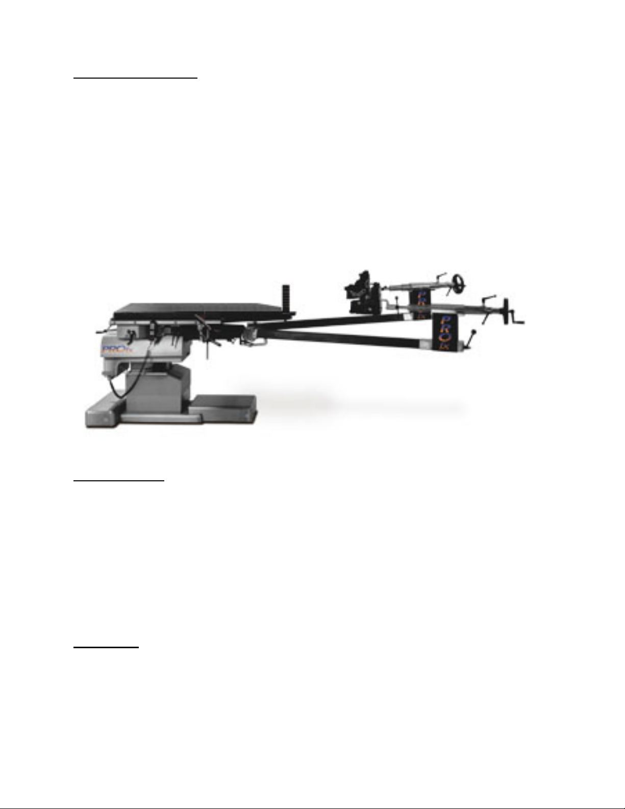
1.1 General Description
The model 6850 PROfx Pelvic Reconstruction Orthopedic Trauma Table (6850 Table) is
designed to safely hold a patient in the proper position undergoing orthopedic or surgical
procedures.
It is a stand-alone, single-pedestal electrically operated table designed to position a patient in a
prone, lateral or supine position during surgical procedures. The table has three primary
electrically powered functions. Up/down, left/right lateral roll, Trendelenburg/Reverse
Trendelenburg tilt. Electromechanical actuator-motors perform these motions.
The table is controlled by means of a hand pendant control with functions clearly labeled.
Positive floor locks are employed to stabilize the table in the operating location.
Figure 1: 6850 Table, right-side view.
1.2 Specifications
The table is designed to safely hold up to a 450-pound patient in the proper procedural position
at any point within its physical range. The table has a height range of 30 to 40 inches. The width
of the tabletop is 21 inches. The length of the tabletop is 62 inches. With leg spars is 125 inches.
The lateral roll range is +/- 20 degrees and the Trendelenburg range is +/- 15 degrees. The
maximum deflection of the tabletop under full load is less than 1 inch at the cantilever end. The
tabletop has a radiolucent equivalency of less that 1-mm of aluminum. The input power
requirement is 110 VAC, 60Hz or 230 VAC AC 50 Hz as indicated on the table label. This is a
Class 1 exempt type B Medical Device with an IPX-0 rating, 10% duty cycle or 6 minutes per
hour.
1.3 Shipping
The 6850 Table must be shipped using appropriate Shipping Crate (OSI part number [p/n] 6800-
400) and Shipping Instructions (p/n NW0408). During shipment the 9650 Table is to be kept in
an environment within the following limits:
1. Ambient temperature -20 degrees C to + 50 degrees C
2. Relative humidity from 10% to 100%, including condensation
3. Atmospheric pressure from 50 to 110 kPa
6850 PROfx Maint. & Repair Manual NW0424 Rev. A
4
Page 6

1.4 Storage
When not in use the table should be stored in a clean dry environment with temperature between
32°F & 120°F.
To insure the battery is always fully charged and ready for use. The table should be stored with
the power plug inserted and attached to an appropriate power source (110VAC or 220VAC) and
the Power Switch turned “ON”.
6850 PROfx Maint. & Repair Manual NW0424 Rev. A
5
Page 7

2.0 CONTROLS IDENTIFICATION
Illuminated Circuit Breaker
2.1 Table Orientation
The major components of the 6850 Table are identified below. The table is described as having
a "head end" and a "foot end". The On/Off Switch, Floor Lock buttons and the Power Cord are
located at the "head end" of the table.
Head-end
Hand Control
Foot-end
Leg Spars
Figure 2: Right-side View with Patient
2.2 Major Controls Location
The Control Panel, On-Off Power Switch, Power Cord receptacle and Model Number/Serial
Number identification label are located at the head-end of the table.
Control Panel
"ON / OFF"
Power Switch and
Power Cord
Receptacle
Floor Lock
Override
(under panel)
6850 PROfx Maint. & Repair Manual NW0424 Rev. A
Model and Serial
Number
Identification
Figure 3: Head-end, Base and Control Panel
6
Floor Lock
Access
(1 of 4)
Page 8
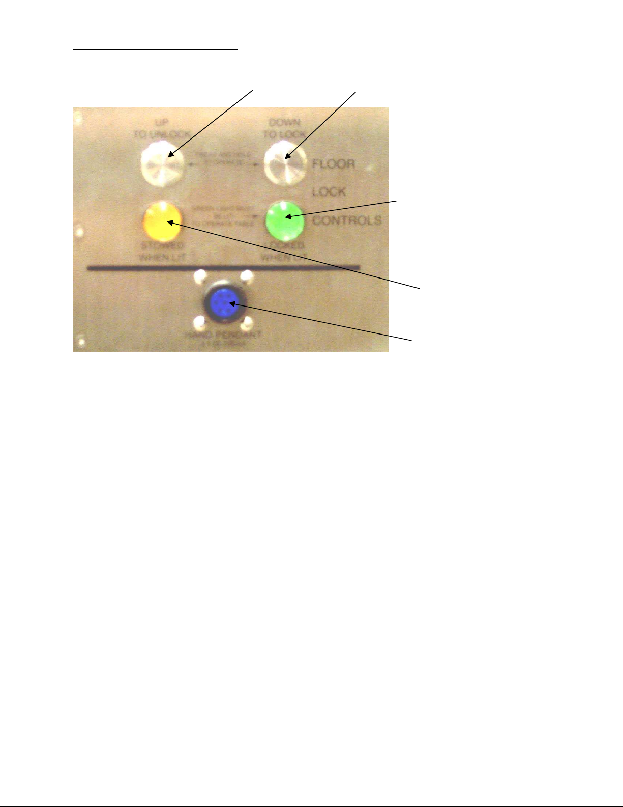
2.3 Control Panel Identification
“DOWN TO LOCK”
Figure 4: Control Panel and Floor Lock Controls
“ UP TO UNLOCK”
Button
Button
“LOCKED WHEN LIT”
Light
“STOWED WHEN LIT”
Light
Hand Control
Receptacle
6850 PROfx Maint. & Repair Manual NW0424 Rev. A
7
Page 9

3.0 INSPECTION
3.1 Acceptance and Transfer
1. Upon receipt of your 6850 Table, remove any protective wrapping or packaging. Visually
inspect all surfaces for freight damage. Check each caster for proper rolling operation.
NOTE: Any freight damage must be reported to the freight carrier immediately upon delivery.
It is the responsibility of the recipient to make freight damage claims.
2. Read the Model/Serial Number Identification Label found at the head end of the base to
confirm the serial number and the input power requirements.
3. Place the 6850 Table, with leg spars attached, in an area with at least 4 feet of clearance on
all sides.
4. Perform Pre-Operational function check.
3.2 Preoperative
Perform Pre-Operational function check.
3.3 Postoperative
Perform Pre-Operational function check.
3.4 Annually
• Inspect and test the 6850 Table as described Pre-Operational function check. Thoroughly
clean the table as described in the CLEANING and MAINTENANCE section of this manual.
Pay special attention to the cleanliness of the controls as excessive soil could affect function.
• Inspect for cuts in the insulation or damage to the connector or power cord.
• On a smooth surface, floor locks engaged, push with minimum of 100lbs force. Table should
not move.
6850 PROfx Maint. & Repair Manual NW0424 Rev. A
8
Page 10

4.0 PRE-OPERATIONAL FUNCTION CHECK
Perform all steps in this procedure. For a complete definition of reference terms used in this
procedure, please refer to the “Glossary of Terms”.
CAUTION: Leg Spars can be damaged if allowed contact with floor. Verify Leg Spars are
raised to maximum, are spread beyond parallel, and all lock handles are
secured.
LA PRUDENCE: les Perches de Jambe peuvent être endommagées si a permis le contact
avec le plancher. Vérifier les Perches de Jambe sont élevées au
maximum, sont étalé au delà de parallèle, et toutes poignées de serrure
sont obtenues.
1. Plug in the Hand Control cable-connector into the "HAND PENDANT" port on the Control
Panel.
2. Plug the power cord into a “hospital grade” power outlet and flip the main “ON/OFF” power
switch to "ON". Verify the switch illuminates; this indicates power is applied to the table.
3. Lockout mode:
3.1. Table is operational when the green “LOCKED WHEN LIT” indicator light, located on
the Control Panel is illuminated and the “FLOOR LOCK STATUS ON” indicator light,
located on the Hand Control, is illuminated.
3.2. With Floor Locks raised, verify that the amber "STOWED WHEN LIT" indicator light
on the Control panel is illuminated and the “FLOOR LOCK STATUS STOWED”
indicator on the Hand Control is illuminated.
3.3. Verify only
the Hand Control operates the Floor Locks when Floor Locks are stowed.
4. Floor lock check using the Control Panel:
4.1. Press and hold “DOWN TO LOCK” button until green “LOCKED WHEN LIT” light is
illuminated. Verify table cannot move on its wheels.
4.2. Press and hold “UP TO UNLOCK” button until amber "STOWED WHEN LIT" light is
illuminated. Verify table is moveable on its wheels.
5. “FLOOR LOCK OVERRIDE" button check:
5.1. Press and hold "FLOOR LOCK OVERRIDE" button located under Control Panel, press
each Hand Control button; Up, Down, Tilt, and Trendelenburg to verify that each
function works without Floor Locks engaged (table locked to the floor).
6. Hand Control check; Cycle all button functions below, to their limits.
6.1. Press and hold "FLOOR LOCK" button. Verify all four locking feet move down and
contact the floor and the green "LOCKED WHEN LIT" light illuminates.
6.2. Press and hold "FLOOR UNLOCK" button. Verify all four locking feet move up and
amber "STOWED WHEN LIT" light illuminates.
6.3. Press and hold "FLOOR LOCK" button to relock table to floor. Verify all four locking
feet move down and contact the floor and the green "LOCKED WHEN LIT" light
illuminates.
6.4. Press and hold "HEIGHT UP" button. Verify Tabletop moves up.
6.5. Press and hold “HEIGHT DOWN" button. Verify Tabletop moves down.
6.6. Press and hold "REV. TREN" button. Verify head-end of tabletop moves up, foot-end
moves down.
6850 PROfx Maint. & Repair Manual NW0424 Rev. A
9
Page 11

6.7. Press and hold "TREN" button. Verify head-end of tabletop moves down, foot-end
moves up.
6.8. Press and hold "LEFT LATERAL ROLL" button. Verify Tabletop rolls to the left.
6.9. Press and hold "RIGHT LATERAL ROLL" button. Verify Tabletop rolls to the right.
6.10. Disorient tabletop by raising height minimum six inches, Left or Right Lateral
Roll the tabletop and Trendelenburg a minimum of five degrees. Press and hold the
"RETURN TO LEVEL" button. Verify Tabletop first levels laterally, levels
Trendelenburg, then after a three-second delay, the tabletop moves down.
6850 PROfx Maint. & Repair Manual NW0424 Rev. A
10
Page 12

5.0 BASIC OPERATION
5.1 Control Operation
Plug the Power Cord into the power cord receptacle, located at the head end of the base and into
a properly grounded receptacle. Refer to the Model/Serial Number label on the head end of the
base for input voltage requirements. Turn "ON" the On-Off power rocker switch (On-Off
Power). The green light in the switch illuminates indicating that power is applied to the table.
This On/Off Power switch is a combination on/off power switch, circuit breaker and pilot light.
5.2 Floor Lock
The Floor Lock button is located on the Control Panel at the head end of the table or on the Hand
Control. To lock the table to the floor, press and hold the “LOCK” button until the Floor Lock is
completely deployed. The green “LOCKED WHEN LIT” indicator light will illuminate when it
is locked. To release the Floor Lock, press and hold the “UNLOCK” button until the Floor Lock
is completely retracted. The green “LOCKED WHEN LIT” light will go dark and the amber
“STOWED WHEN LIT” light will illuminate when it is unlocked.
NOTE:
The table will not function until the Floor Lock is completely deployed and green “LOCKED
WHEN LIT” light is illuminated.
5.3 Moving the Table
Once the Floor Locks are unlocked the table can be rolled for relocation. It is best that the table
be rolled with the Head End forward (Leg Spars trailing).
5.4 Hand Pendant Control
See Figure 5.
The 6800 Table is controlled by means of a Hand Control Pendant (Hand Control). The Hand
Control is plugged into the receptacle labeled “HAND PENDANT” on the Control Panel. Plug in
Hand Control connector and rotate screw-locking collar until hand tight. To operate any of the
desired functions, press and hold the appropriate button on the Hand Control until the desired
position is achieved.
The Hand Control is equipped with a "RETURN TO LEVEL" button. This button is used to
level first the lateral roll, second the Trendelenburg, and third brings the table to its lowest
position. A delay of 3 seconds is expected after the Trendelenburg function before returning to
its lowest position.
The controller considers the table to be level if it is within +/- 2 degrees. If the "RETURN TO
LEVEL" button is pressed while the table is within this range, it will not move. If it is required
to adjust the table to a position closer to zero degrees, press the appropriate function button on
the Hand Control until the desired position is achieved.
6850 PROfx Maint. & Repair Manual NW0424 Rev. A
FLOOR LOCK STATUS
11
Page 13

FLOOR LOCK
ON
STOWED
RETURN
TO
LEVEL
FLOOR
FLOOR
UNLOCK
LOCK
Battery Status
Green-OK
Red-Charge
(800) 777-4674
Figure 5: Hand Pendant Control (Hand Control)
5.5 Leg Spars:
The 6850 Table is equipped with two adjustable patient leg spars. Each will articulate
horizontally and vertically to accommodate a variety of patient positions and surgical
procedures. Additional patient leg rotation and traction is available.
CAUTION: Leg Spars can be damaged if allowed contact with floor during table
operation. Clear area of any obstructions or obstacles during table movement.
LA PRUDENCE: les Perches de Jambe peuvent être endommagées si a permis le contact
avec le plancher pendant l'opération de table. Eclaircir de n'importe
quelles obstructions ou de n'importe quels obstacles pendant le
mouvement de table.
Figure 6: 6850 Table with Leg Spars attached.
6850 PROfx Maint. & Repair Manual NW0424 Rev. A
12
Page 14

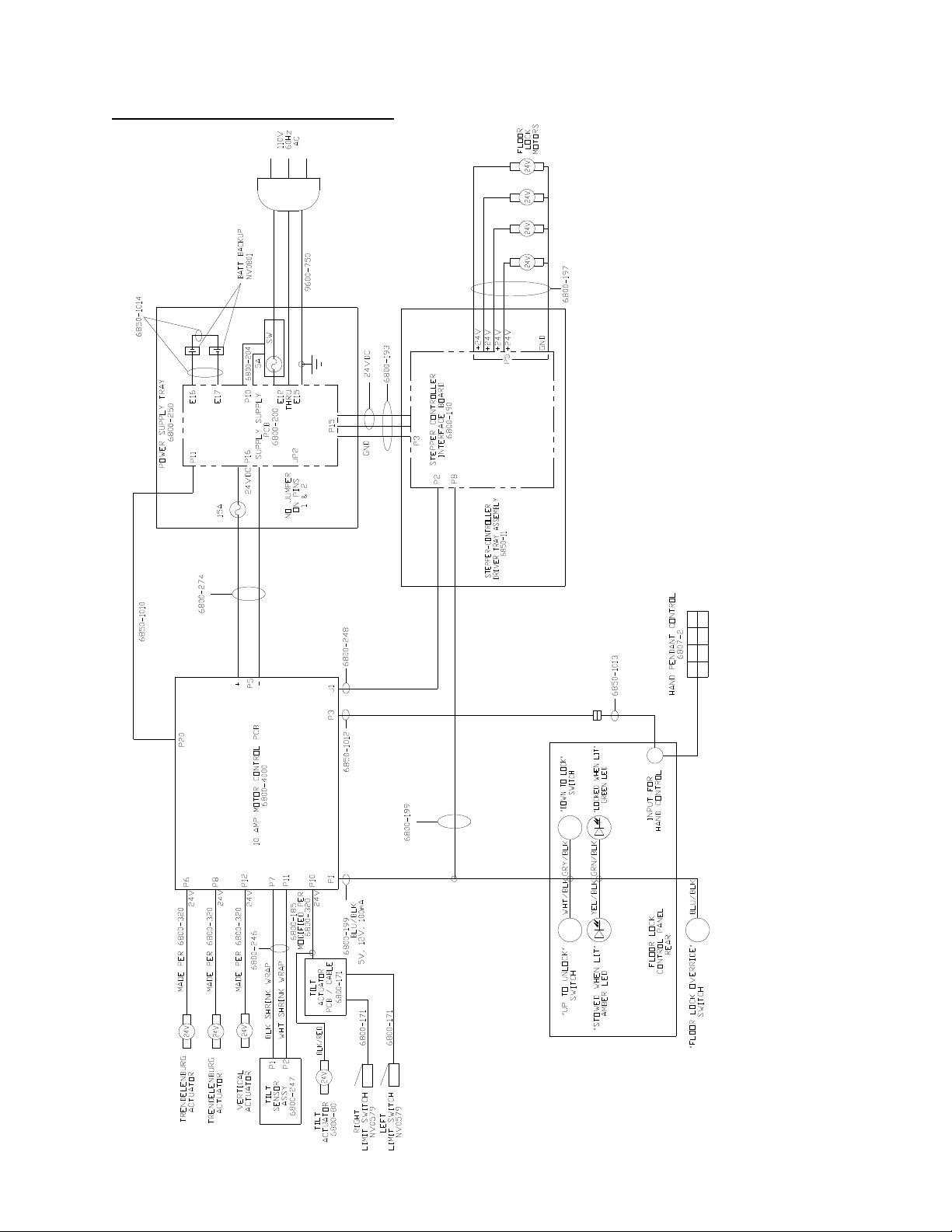
6.0 THE ELECTRICAL SYSTEM
6.1 Description
The electrical system provides control of all table functions and is comprised of a power cord, an
On/Off circuit-breaker switch, wire harnesses, a power supply, a controller circuit, a Hand
Control, floor lock jackscrew-actuators, and various electromechanical actuators. The electric
motor-driven lead-screw type actuators manipulate the table height; the Hand Control controls
lateral roll and trendelenburg functions. The Floor Lock buttons raise and lower the table onto
the floor locks. The input power requirement is 120 VAC 60Hz, 6.5 Amp or 230 VAC 50Hz as
indicated on the Serial Number label. Refer to 6850 Table Electrical Interconnect Diagram
(drawing number 6850-1001).
6.2 On/Off Power Switch
An illuminated On/Off main power switch and circuit breaker is located on the head-end of the
table base. When illuminated, it indicates that the table is plugged into a live electrical outlet and
the power is on. This switch also serves as a high-voltage 120/240-volt circuit breaker. In the
event of an overload condition this switch will trip off. To reset, push circuit-breaker switch to
the "OFF" position and then the "ON" position.
NOTE:
Determine the source of the overload prior to resetting this switch.
6.3 Component Circuit Breaker
The electrical system includes individual component 24-volt circuit breakers, located at the headend of the table base. If a short circuit occurs the low voltage circuit breaker will trip as
indicated by a button protruding from the access hole. To reset, press the button in and release.
NOTE:
Determine the source of the overload prior to resetting this button.
6.4 Power Cord
The table is equipped with a detachable standard EIC power cord with the appropriate 120 VAC
hospital grade connector (230volt versions do not include the power connector). The power cord
is connected to the table at the EIC power entry socket located near the "ON/OFF" switch, at the
pedestal end of the table base.
6.5 Leakage Current
The 6850 Table is designed and tested not to exceed 100 micro amps of leakage current.
6850 PROfx Maint. & Repair Manual NW0424 Rev. A
13
Page 15

6.6 Floor Lock System
Floor Lock Button
Floor Lock Indicator Lights
Floor Lock Override Button
located under panel
Manual Floor Lock access
for Crank Handle
Figure 7: Head-end Base and Control Panel
The Floor Lock System secures the 6850 Table by powering four (4) jackscrews, lowering four
legs onto the floor and unloading table weight off of the four swivel casters. The controller
monitors each individual Floor Lock for contact with the floor and requires that each Floor Lock
be completely engaged before any other table function can be operated. In the case of an uneven
floor, it is possible that one or more legs will continue to extend until firm contact is made.
To lock the Floor Lock:
Press and hold the Hand Control "FLOOR LOCK" button or Control Panel "DOWN TO LOCK"
button. When locked, the Hand Control "FLOOR LOCK ON" light, and Control Panel, green
“LOCKED WHEN LIT” light illuminates, indicating that all four feet are locked.
To unlock the Floor Lock:
Press and hold the Hand Control “FLOOR UNLOCK” button or Control Panel "UP TO
UNLOCK" button. When unlocked, the Hand Control "FLOOR LOCK STOWED" light and
Control Panel, amber “STOWED WHEN LIT” light illuminates, indicating that all four feet are
completely retracted.
“FLOOR LOCK OVERRIDE” Button:
If Floor Lock System fails during table use, press and hold the “FLOOR LOCK OVERRIDE”
button while simultaneously operating the desired Hand Control function. Once released, no
functions will be operable and this button must be pressed again if subsequent table movement is
required.
NOTE: This Override Button only powers the height, Trendelenburg, and Lateral Roll functions
via the Hand Control and is intended for emergency situations only.
To restore Floor Lock System function:
• Verify Power Cord is plugged into a live power outlet supplying proper voltage and the
"ON/OFF" Power Switch is on and illuminated.
• Verify all four Floor Locks are completely engaged and Control Panel, green “LOCKED
WHEN LIT” light illuminates.
6850 PROfx Maint. & Repair Manual NW0424 Rev. A
14
Page 16

To manually disengage Floor Lock for table relocation:
1. Use Floor Lock Crank Handle (p/n 6800-230) stowed on sheet metal housing behind Control
Panel for each Floor Lock.
2. Remove Floor Lock access hole-plug and insert Crank Handle to engage Floor Lock shaft.
3. For Floor Lock nearest grounding stud/Power Cord, turn Crank Handle clockwise to raise
Floor Lock.
4. For all other Floor Locks, turn Crank Handle counter-clockwise to raise Floor Lock.
6.7 Emergency Backup Battery System
The 6850 Table is equipped with an emergency battery backup system. The system batteries are
automatically charged while the table is plugged into a proper power source and the ON/OFF
power switch is switched "ON".
Battery charge status in shown via a light on the Hand Control labeled "Battery Status".
If illuminated green = OK.
If illuminated red = charge.
Due to the relatively low drains of the 6850 Table, the table could be used only on the backup
batteries for up to several hours of continuous use, but are intended for emergency use during
loss of power.
If recharge is required, charge a minimum of 3 hours. A full charge should be available after 18
hours.
Both batteries should be replaced every five (5) years or as needed. See Emergency Backup
Battery Replacement section.
6.8 Troubleshooting
In the event of a table malfunction:
• Check input power; verify Power Cord is plugged into a live electrical outlet.
• Verify Power Switch is “ON”; the switch illuminates green.
• Verify the Floor Lock is locked to the floor; press the “FLOOR LOCK” button until the
green “LOCKED WHEN LIT” light is illuminated.
• Use the “FLOOR LOCK OVERIDE” button to temporarily bypass the interlock of the Floor
Lock system.
NOTE: This Override Button only powers the height, Trendelenburg, and Lateral Roll
functions via the Hand Control and is intended for emergency situations only.
6850 PROfx Maint. & Repair Manual NW0424 Rev. A
15
Page 17

7.0 CLEANING and MAINTENANCE
7.1 Cleaning and Disinfecting
NOTE: Never pour any liquid directly onto the table. Never subject the 6850 Table to an
equipment washing machine.
USE OF IODOPHORS WILL CAUSE STAINING.
Table Exterior:
1. Exterior surface should be regularly wiped clean with a mild detergent solution and wiped
dry with a soft lint-free cloth.
2. Care should be taken to avoid exposing the table to excessive moisture. Flooding, fogging or
steam cleaning is not recommended.
3. Blood or other fluids, etc., if allowed to remain on the table for a long period of time, will
require special cleaning to remove. A 5% acetic acid solution or white vinegar and water
solution is especially good for this purpose.
4. Cleaning with a good commercial cleaning compound, such as Stainless Steel Magic or
Acme White Finish, and then buffing the surface by hand can correct staining and
discoloration of plated or stainless steel surfaces only.
5. To disinfect exterior surfaces use a quaternary ammonium or similar type disinfectant
compound according to manufacturer's directions for use. Wipe dry with a soft lint-free
cloth.
NOTE: Failure to thoroughly dry surface after cleaning and disinfecting may result in rust.
Casters:
Casters should be cleaned and disinfected in the same manner as table exterior. Access to the
casters is achieved by removing the sheet metal enclosures at each end of the table base.
NOTE: Before removing any sheet metal covers the table must be turned off and unplugged.
Dangerous high voltage may be present in the circuitry under the covers. Only trained
technicians should perform this task.
7.2 Maintenance
Routine table care will assure many years of trouble-free service.
Lubrication:
All components are lubricated for life at the factory and no other lubrication on the table is
necessary.
Preventative Maintenance:
Contact OSI Technical Service for a complete Preventative Maintenance Checklist.
6850 PROfx Maint. & Repair Manual NW0424 Rev. A
16
Page 18

8.0 REMOVAL and REPLACEMENT of COMPONENTS
8.1 Floor-lock Actuator
Floor Lock
(lowered)
Coupling
and Set-screw
Support Block
Floor Lock
(raised)
Crank Handle
Figure 8: Foot-end Base with cover removed, raised with support block and Crank Handle.
1. Flip on
main “ON/OFF” power switch. The switch illuminates, indicating power is to the
table.
2. Lock table to floor; Press and hold “DOWN TO LOCK” button until green "LOCKED
WHEN LIT" light is on.
3. Flip off
main “ON/OFF” power switch. Wait 30 seconds for discharge. Unplug power cord
from properly grounded wall outlet.
4. Remove base-access cover from end of table needing floor lock replacement.
CAUTION: Electrical shock hazard exists with access covers removed; use caution
when working in exposed areas.
LA PRUDENCE: Le danger de choc Electrique existe avec les couvertures d'accès
enlevées; la prudence d'usage en travaillant dans les domaines
exposés.
a. Remove two white-plastic access plugs for the Floor Lock using small slotted
screwdriver.
b. Remove four screws attaching the cover using a 1/8-inch hex key.
c. Remove access cover.
5. Raise end of table using Floor Lock Crank Handle (p/n 6800-230 supplied with table). See
photo above.
6. Place 2-1/2 inch high support-block under Floor Lock motor-mount.
7. Carefully lower table onto support-block using Floor-lock Crank Handle.
CAUTION: Make certain table remains stable.
LA PRUDENCE: Faire la certaine table restes écurie.
8. Raise Floor Lock off the floor to its maximum height, using Floor-lock Crank Handle.
9. Loosen Floor-lock actuator coupling setscrew using 1/8-inch hex key, slide coupling towards
actuator.
10. Remove actuator by removing the two socket-head cap screws using 3/16-inch hex key.
6850 PROfx Maint. & Repair Manual NW0424 Rev. A
17
Page 19

11. Replace Floor-lock Actuator (p/n 6800-217) or Pad (as described below).
M6-1.00 x 35 mm Bolt
12. Reassemble in reverse order.
13. Verify proper function using Pre-Op Function Check.
8.2 Floor-lock Pad
If only the Floor-lock pad requires replacing.
1. Remove Brake Pad (p/n MZC700004B0) by removing M6-1.00 x 20mm socket-head bolt
(p/n MZA00206200) using 5mm hex key.
2. If the standard attachment bolt is bent; the first threads may be damaged requiring
replacement with an optional, longer M6-1.00 x 35mm (p/n AAM6035CAN).
3. Install replacement Brake Pad with attachment bolt and washer using 5mm hex key.
Floor Lock
Actuator Jack
Screw
Figure 9: Floor Lock Actuator Assembly.
6850 PROfx Maint. & Repair Manual NW0424 Rev. A
Floor Lock Pad
18
Page 20

8.3 Emergency Backup Battery
The following information is on the battery replacement-warning label located inside the battery
cover.
If battery fails to hold a charge it should be replaced. Replace only with identical type and size
battery. Replace both batteries at the same time. Also replace foam battery blocks on top of
battery. Batteries should be replaced once every five (5) years. Whenever this cover is opened,
check battery for signs of corrosion. Battery terminals should be clean and free from corrosion,
oil, grease, dirt, or other contaminants. Install batteries per included diagram.
WARNING:
Connect batteries only with power cord unplugged and main switch “OFF”
.
Connect battery terminals as follows:
Red Wire: Positive terminal of battery “A” to terminal E16 on power supply.
Yellow Wire: Negative terminal of battery “A” to positive terminal of battery “B”.
Black Wire: Negative terminal of battery “B” to terminal E17 on power supply.
Perform the following test:
Make sure power cord is unplugged
.
Turn “ON” main power (utilizing battery power).
Observe all LED lights on Hand Control turn on and off sequentially.
Note: If this does not happen, turn “OFF” main power immediately and check if connection of
battery is correct and Hand Control is fully connected to the receptacle on the table, then
try above test again. If this does not solve the problem, contact OSI Technical Support at
800-777-4674 for further assistance.
When correctly connected and main power switch is “ON” and power cord unplugged, battery
status indicator light on Hand Control will show green or red.
A green battery-status light indicates batteries are charged and installed correctly.
A red battery-status light indicates batteries are connected correctly but are in need of charging.
Charge for at least three (3) hours by plugging power cord into wall receptacle and turn table
power “ON”. Make sure green indicator on circuit breaker in on (AC is provided to the charger).
Battery Type: Gel cell LED acid batteries, 12 Volt 12 Amp-hour rating.
Battery Size: 150mm long, 98mm wide, 100mm deep.
Battery OSI ordering number: NVO801
Foam battery block OSI ordering number: 6850-195
Figure 10: Head-end base, cover removed, Power Supply Assembly
6850 PROfx Maint. & Repair Manual NW0424 Rev. A
19
Page 21

8.4 10 Amp Motor-control PCB
See 9.5 Table Assembly, Exploded View.
1. Flip off the main “ON/OFF” power switch, and wait 30 seconds
cord from wall outlet.
2. Remove foot end base cover by removing the four screws using 1/8 in hex key.
3. Lift off foot end base cover.
4. Unplug cables from 10 Amp Motor-controller PCB. See Interconnect Diagram.
CAUTION: Cable connectors are not marked, mark as needed.
a. J1 "TO STEPPER CONTROLLER" -
b. P1 "TO INTERUPT" - to Stepper Controller/Component Interface.
c. P2 "TO PC" - no connection.
d. P3 "KEYPAD" - Extension Cable (p/n NV0564) to Hand Control.
e. P4 "OUTPUT" - no connection.
f. P5 "POWER IN" - Power Cable (p/n 6800-274) to DC Power Supply.
g. P6 - white marked cable to Trendelenburg Actuators.
h. P7 - to Tilt Sensor Assy. (p/n6800-247).
i. P8 - blue marked cable to Trendelenburg Actuators.
j. P10 - orange marked cable to Tilt Actuator.
k. P11 - to Tilt Sensor Assy. (p/n6800-247).
l. P12 - yellow marked cable to Vertical Actuator.
m. P13, P15, P17 - no connection.
n. P18 "INPUT" - no connection.
o. P20 – to Power Supply P11, battery feedback monitor.
5. Remove the two #10 socket-head screws attaching the 10 Amp Motor-controller PCB
mounting bracket (located under the PCB).
6. Lift the mid-section base cover and remove the two #10 socket-head screws attaching the 10
Amp Motor-controller PCB mounting bracket.
7. Carefully lift out the two #10 socket-head screws attaching the 10 Amp Motor-controller
PCB assy.
8. Reassemble in reverse order.
for discharge. Unplug power
6850 PROfx Maint. & Repair Manual NW0424 Rev. A
20
Page 22

8.5 Power Supply Tray
See 9.5 Table Assembly, Exploded View.
Figure 11: Head-end base with cover removed, Power Supply removal.
1. Flip off
cord from wall outlet.
2. Remove head end base cover by removing the six screws using 1/8 in hex key.
3. Unplug small 3-wire connector P11.
4. Unplug 3-wire connector P 15.
5. Unplug 2-wire connector P 16.
6. Remove 3/8-inch hex bolt from ground stud using 9/16-inch wrench and remove top two
green / yellow striped wires.
7. Remove three socket-head screws on each side of power supply tray and loosen two socket-
head screws at front of tray using 5/32-inch hex key.
8. Remove Power Supply Tray by carefully lifting out of base casting.
9. Install in reverse order.
the main “On/Off” power switch, and wait 30 seconds for discharge. Unplug power
6850 PROfx Maint. & Repair Manual NW0424 Rev. A
21
Page 23

8.6 Stepper-controller Tray
See 9.5 Table Assembly, Exploded View.
Figure 12: Stepper-controller Tray Assembly
1. Flip off
cord from wall outlet.
2. Remove foot end base cover by removing the six screws using 1/8-inch hex key.
3. Lift off cover.
4. Unplug cables from Stepper Controller PCB. See Interconnect Diagram.
CAUTION: Cable connectors are not marked, mark as needed.
LA PRUDENCE: les connecteurs de câble ne sont pas marqués, la marque comme
nécessaire.
a. J1 and J2 - no connection.
b. P1 - no connection.
c. P2 - Com Port.
d. P3 - Power In.
e. P4 - Power Out.
f. P6 - Senders
g. P7 - Analog I/O
h. P8 - Digital I/O
5. Remove ground wires from the ground stud using 3/8-inch wrench.
6. Remove two socket-head screws attaching the tray, closest to the table pedestal, using 5/16-
inch hex key.
7. Loosen two, horizontal, socket-head screws, attaching the tray, using 5/16-inch hex key.
8. Carefully lift out the Controller Tray.
9. Install in reverse order.
the main “On/Off” power switch, and wait 30 seconds for discharge. Unplug power
6850 PROfx Maint. & Repair Manual NW0424 Rev. A
22
Page 24

8.7 Tilt Sensor-Actuator
1. Flip on
main “ON/OFF” power switch. The switch illuminates, indicating power is in the
table.
2. Press and hold “DOWN TO LOCK” button until green "LOCKED WHEN LIT" light is lit.
3. Move tabletop to highest position using Hand Control.
4. Flip off
main “ON/OFF” power switch. Wait 30 seconds for discharge.
5. Pivot both Leg Spars outward to their maximum limits.
6. Remove left and right Leg Spars per User Guide procedures.
Pivot Frame Cover Removal:
See Figure 13.
1. Remove left and right “Spar Position” crank handles using 1/8-inch hex key.
2. Remove left and right ‘Spar Position Lock” handle-knobs by firmly rotating counter-
clockwise.
3. Remove “Accessory Bracket Remove/Attach” crank handle using 3/16-inch hex key.
4. Remove four button-head screws, located at top of cover using 1/8-inch hex key.
5. Carefully remove Pivot Frame Cover.
Left and Right “Pivot Frame Front” Cover Removal:
Not shown, but located at far end from Pivot Frame Cover.
1. Carefully pry off each cover (held in place with double-backed tape).
Left Bell Cover Removal:
See Figure 13.
1. Remove seven flat-head screws, located on top, front and back, using 1/16 hex key.
2. Remove two screws, located on top surface of cover, using 1/8 hex key
3. Remove cover.
CAUTION: To prevent damage to the sensors use care removing or replacing this
cover.
LA PRUDENCE: Empêcher des dommages au soin d'usage de détecteurs pour enlever
ou remplacer cette couverture.
“Spar Position Lock”
Handle
“Spar Position”
Crank Handle
“Accessory Bracket
Remove/Attach”
Handle
Pivot Frame
Cover
Bell Cover,
Left
Bell Cover,
Right
Figure 13: Head-end - Pivot Frame and Bell Covers, Spar Lock Handles.
6850 PROfx Maint. & Repair Manual NW0424 Rev. A
23
Page 25

Tilt Sensor removal:
1. Cut any cable ties holding the existing tilt sensor wire-harness to the tilt sensor bracket.
2. Gently pull the two sets of wires from the tilt sensor.
NOTE: The color-coding, white-marked connector into white-marked "Tilt Adjust" socket,
black-marked connector into black-marked "Trend Adjust" socket.
3. Remove original tilt sensor by removing two 1/4-20x1/2 in. cap-head screws using 3/16 hex
key.
Replacement Tilt Sensor installation:
1. Using 3/16 hex key, attach the replacement tilt sensor with the two ¼-20 screws.
2. Plug in wire harnesses connecting to tilt sensor. Connect the white shrink-tube-marked
connector into white-marked "Tilt Adjust" socket, black shrink-tube-marked connector into
black-marked "Trend Adjust" socket.
3. Attach harness to sensor bracket, as needed, with small nylon cable tie. “Do not over tighten
wires” Use care to prevent possible damage by moving parts.
Tilt Sensor Calibration:
NOTE: Use bubble level, resting on the tabletop, as level gauge. The level sensor adjustment
screws are accessed from top of unit. A two-degree maximum dead-band exists for axis.
For "Return-to-level" to function, tabletop must be outside of this dead-band.
1. Flip on
table.
2. Press and hold “DOWN TO LOCK” button until green "LOCKED WHEN LIT" light
illuminates.
3. Raise the tabletop to a comfortable level.
4. Push " LEFT LATERAL ROLL" or "RIGHT LATERAL ROLL" buttons to level tabletop.
5. Push "LEFT LATERAL ROLL" button to lateral roll tabletop more than five degrees.
6. Push "RETURN-TO-LEVEL" button to level tabletop; note degree of level.
7. Push "RIGHT LATERAL ROLL" button to lateral roll tabletop more than five degrees.
8. Push and hold "RETURN-TO-LEVEL" button to level tabletop; note degree of level.
9. Turn the "Tilt Adjust" screw a partial turn.
NOTE: Clockwise will stop tabletop more to the right, counter-clockwise will stop tabletop
10. Test the adjustment by:
10.1. Push "LEFT LATERAL ROLL" button to tilt tabletop to maximum.
10.2. Push "RETURN-TO-LEVEL" button to level tabletop; note the degree of level.
10.3. Push "RIGHT LATERAL ROLL" button to tilt tabletop to maximum.
10.4. Push "RETURN-TO-LEVEL" button to level tabletop; note the degree of level.
11. Continue adjustments until tabletop stops from either maximum lateral roll at same offset
from zero.
12. Trendelenburg / Reverse-Trendelenburg calibration.
12.1. Repeat steps of "Left and Right Lateral Roll" calibration using "Trendelenburg /
13. Push the illuminated "ON/OFF" switch to off
discharge
14. Reattach Left Bell Cover with seven screws using a 1/16-inch hex key.
CAUTION: Use care replacing this cover to prevent damage to the sensors.
LA PRUDENCE: le soin d'Usage pour remplacer cette couverture pour empêcher des
dommages aux détecteurs.
main “ON/OFF” power switch. The switch illuminates, indicating power is in the
more to the left. Tabletop will overshoot each stopping point, requiring "splitting
the difference" to adjust for proper balance.
Reverse-Trendelenburg".
, green light goes out. Wait 30 seconds for
6850 PROfx Maint. & Repair Manual NW0424 Rev. A
24
Page 26
9.0 TECHNICAL DRAWINGS and PARTS LISTS
9.1 Interconnect Diagram, 120VAC
6850 PROfx Maint. & Repair Manual NW0424 Rev. A
25
Page 27

9.2 Interconnect Diagram, 220VAC
6850 PROfx Maint. & Repair Manual NW0424 Rev. A
26
Page 28

9.3 Table Assembly Bill of Materials
50 AAAT031AAC #10-32 X .31 SST BTN HD SKT SCR 24
49 AAAT025HJA #10-32 X .25 SELF LOCKING SKT SET SCR 2
48 AAAT025AAC #10-32 X .25 SST BTN HD SKT SCR 4
47 AAAM037CAC #6-32 X .37 SST CAP HD SKT SCR 1
46 AAAK025AAC #5-40 X .25 SST BTNHD SKT SCR 4
45 AAAH031BAC #4-40 UNC X .31 FLAT HEAD SOCKET SCREW, SS 16
44 AAAH018BAC #4-40 UNC X .188 FLAT HEAD SOCKET SCREW, SS 6
43 9650-231 1/2 IN RUBBER CUSHIONED STEEL LOOP CLAMP 6
42 9650-227 .375 INCH PLASTIC CABLE CLAMP 9
41 6800-271 BELLOWS MOUNT 2
40 6800-270 TILT COVER , RIGHT 1
39 6800-269 TILT COVER, LEFT 1
38 6800-268 COLUMN SKIRT, FIXED, RIGHT 1
37 6800-267 COLUMN SKIRT, FIXED, LEFT 1
36 6800-263 X-RING COVER , RIGHT 1
35 6800-262 X-RING CO VER, LEFT 1
34 6800-260 BELLOWS SUPPORT 2
33 6800-259 BELLOWS 2
32 6840-11 CONTROLLER TRAY ASSEMBLY 1
31 6800-250 POWER SUPPLY TRA Y ASSEMBLY 1
30 6800-249 TILT SENSOR SPACER 1
29 6800-247 T ILT SENSOR ASSEMBLY 1
28 6800-239 ASSY, 10 AMP MOTOR CONTROL 1
27 6800-230 ASSEMB LY, MANUAL FLOOR LOCK CRANK 1
26 6800-229 X-RING WITH BUSHINGS ASSY 1
25 6800-208 FLOOR LOCK LED YELLOW 1
24 6800-207 FLOOR LOCK LED GREEN 1
23 6800-171 TILT MOTOR LIMIT SWITCH ASSY 1
22 6800-174 BRKT, TILT MTR LIM SW MNT 2
21 6800-173 PC BOARD MOUNT, TILT MOTOR 1
20 6800-133 BASE COVER, FRONT 1
19 6800-132 BASE COVER, BACK 1
18 6800-130 BASE COVER, MID SECTION 1
17 6800-129 COLUMN SKIRT FLOATING 1
16 6800-127 COLUMN SLIDER COVER 1
15 6800-99 PIN , TRENDELENBURG 2
14 6800-98 PIN ,TILT, BACK 1
13 6800-97 PIN, TILT, FRONT 1
12 6800-96 SWIVEL BRACKET MOUNT WASHER 2
11 6800-95 PRESSURE PLATE, TILT ACTUATOR MOUNT 1
10 6800-94 SWIVEL BRACKET ADJUSTMENT BRACKET 1
9 6800-90 SWIVEL BRACKET WELDMENT, TILT 1
8 6800-80 ASSEMBLY, TILT ACTUATOR 1
7 6800-79 TILT AXIS WORM GEAR 1
6 6800-77 TILT WORM GEAR SHIM, .010 2
5 6800-75 TILT WORM GEAR SHIM, .002 1
4 6800-54 SHIM, 1.00 DIA PIN 6
3 6800-38 Y-RING MACHINED 1
2 6800-37 TRENDELENBURG ADJUSTMENT LEVER, X-RING 1
1 6800-7 BASE FEET AND COLUMN SUBASSEMBLY 1
ITEM PART NO. DESCRIPTION QTY
98 NV0711 MOLEX SOCKET CRIMP 28-22 AWG 16
97 NV0630 CON NECTOR HOUSING , MALE , 8 CIRCUIT 39-01-2080 4
96 6800-76 TILT WORM GEAR SHIM, .005 1
95 6800-274 10 A MOTOR CONTROL POWER CABLE 1
94 6800-248 CABLE ASSY., FLAT RIBBON M-F DB9 1
93 6800-246 TILT SENSOR WIRE HARNESS 1
92 6800-199 DIGITAL I/O W IRE HARNESS 1
91 6800-197 FLOOR LOCK HARNESS ASSY. 1
90 6800-193 CABLE ASS Y, PWR SPL TO STEPPER CONTROLER 1
89 6800-119 TILT WORM GEAR SHIM .O239 THICK 2
88 6800-118 TILT WORM GEAR SHIM .OO7 THICK 2
87 9650-225 .25 INCH PLASTIC CABLE CLAMP 1
86 NV0649 .75 INCH PLASTIC CABLE CLAMP 3
85 6800-185 ACTUATOR POWER CORD 1
84 NV0650 1 INCH PLASTIC CABLE CLAMP 5
83 NV0587 STAINLESS STEEL BUTTON 4
82 NV0259 3/8 IN RUBBER CUSHIONED STEEL LOOP CLAMP 3
81 NL1255 ACTUA TOR, ELEC., 100mm, LINAK 2
80 NG0752 #10-32 PEM SELF CLINCHING SS 8
79 NB0339 EAGLE P LASTIC NYLON HOLE PLUG Ø1.00 4
78 KA0060400 1/16 X 4 1/2 NEOPRENE RUBBER W/ADH 24 "
77 AJ0117 RETAINING RING EXTE RNAL 1" DIA, BLK PHS 4
76 AE019050KF SHOULDER WASHER #10 NYLON 4
75 AE018037D STAR LOCK WASHER, INTERNAL, .18 X .37 3
74 MZA30108030 8 mm HEX NUT 10
73 ADATA #10-32 HEX NUT 3
72 NV0564 CABLE , HANDSET EXTENSION 2.4 M LONG 1
71 AC012025 POP RIVE T, .12 X .25 LG 8
70 AAM10045FA 10mm DIA. X 45mm LG, SKT HD SHLDR SCR 1
69 AAM10035FA 10mm DIA. X 35mm LG, SKT HD SHLDR SCR 1
68 AAM10030FA 10mm DIA. X 30mm LG, SKT HD SHLDR SCR 3
67 AABF125CA 1/2-13 X1.25 CAP HD SKT SCR 2
66 AABB075HA 3/8-16 X .75 SCK SET SCR 1
65 AABB175DD A 3/8 -16 X 1.75 HEX HEAD CAP SCREW GRADE 8 1
64 AABB075CAA 3/8-1 6 X .75 CAP HD SKT SCR GRADE 8 3
63 AAAY350DD 5/16 -18 X 3.5 HEX HEAD CAP SCREW 2
62 AAAW125CA 1/4-20 X 1.25 CAP HD SKT SC R, 2
61 AAAW075CA 1/4-20 X .75 CAP HD SKT SCR 3
60 9600-450 T-CABLE ASSEMBLY, HANDSET 1
59 AAAW050CA S CREW, CAP, HEX, 1/4-20 UNC-2A X .50L 2
58 AAAW050BAC 1/4 X 20 FLAT HEAD SOCKET SCREW 4
57 AAAT075HA #10-32 X .25 SST SKT SET SCR 1
56 9650-431A CABLE, HANDSET EXTENSION 20 IN 1
55 AAAT075AAC #10 -32 X .75 SST BTN HD SKT SCR 4
54 AAAT050HAC #10-32 X .50 SST SKT SET SC R 1
53 AAAT050BAC #10-32 X .50 SST FLHD SKT SCR 2
52 AAAT050AAC #10 -32 X .50 SST BTN HD SKT SCR 10
51 AAAT037AAC #10 -32 X .37 SST BTN HD SKT SCR 51
9.4 Replacement / Spare Parts List
Hand Control…………….…………………..………………..p/n (part number) 6800-238
Power Supply Tray Assembly…………..………………………….…..…….p/n 6800-250
Power Cord, Right Angle………......….….………………………….…...….p/n 9600-750
Power Cord Receptacle………………………………...……………….……..p/n NV0585
LED (Light Assembly), Amber……………………….…………….....……..p/n 6800-208
LED (Light Assembly), Green……………………….…….………......…….p/n 6800-207
Floor Lock Assembly……………………………………...……………..…..p/n 6800-210
Floor Lock Pad…………………………………...………..……....….p/n MCZ700004B0
10 Amp Motor-Controller PCB Assembly………..….……………....…..….p/n 6800-239
Stepper-Controller/Driver PCB Tray Assembly……………………..………..p/n 6840-11
Tilt Actuator Motor Assembly…………….…..………….……………..….…p/n 6800-80
Tilt Sensor Assembly……..………………….………………………………p/n 6800-247
Emergency Backup Battery (two required)……………….……………….….p/n NV0801
6850 PROfx Maint. & Repair Manual NW0424 Rev. A
27
Page 29

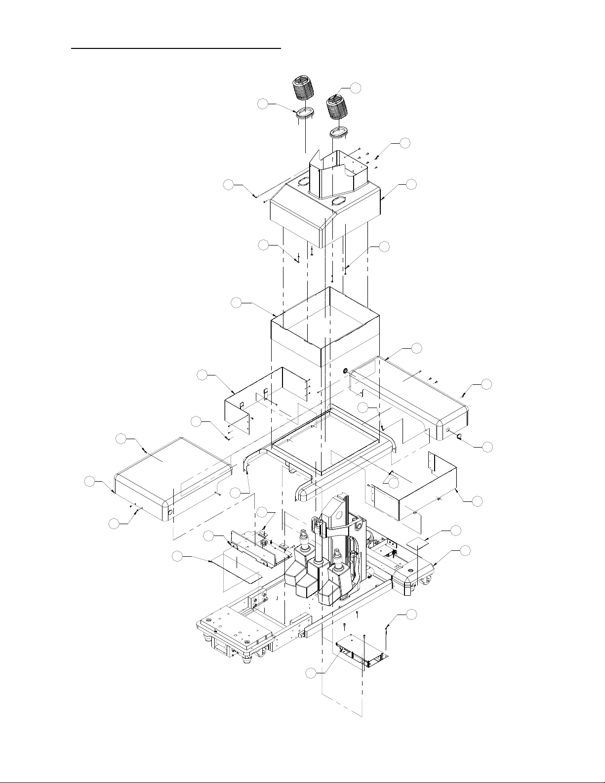
9.5 Table Assembly Exploded View
3
13
57
14
Y-Ring Assembly
54
4
26
X-Ring Assembly
10 Amp-Controller
Stepper-Controller
66
74
68
77 4X
15 2X
70
2
61
812X
Power Supply
682X
744X
84 4X
31
504X
81 (REF)
84
50
68
Base Assembly
6850 PROfx Maint. & Repair Manual NW0424 Rev. A
28
Page 30
9.6 Base Cover Assembly, Exploded View
412X
33
51 6X
552X
484X
17
38
512X
456X
512X
16
76 4X
19
51 4X
79 4X
20
18
522X
514X
32
78REF
28
51 2X
37
78 REF
1
51 4X
6850 PROfx Maint. & Repair Manual NW0424 Rev. A
29
Page 31
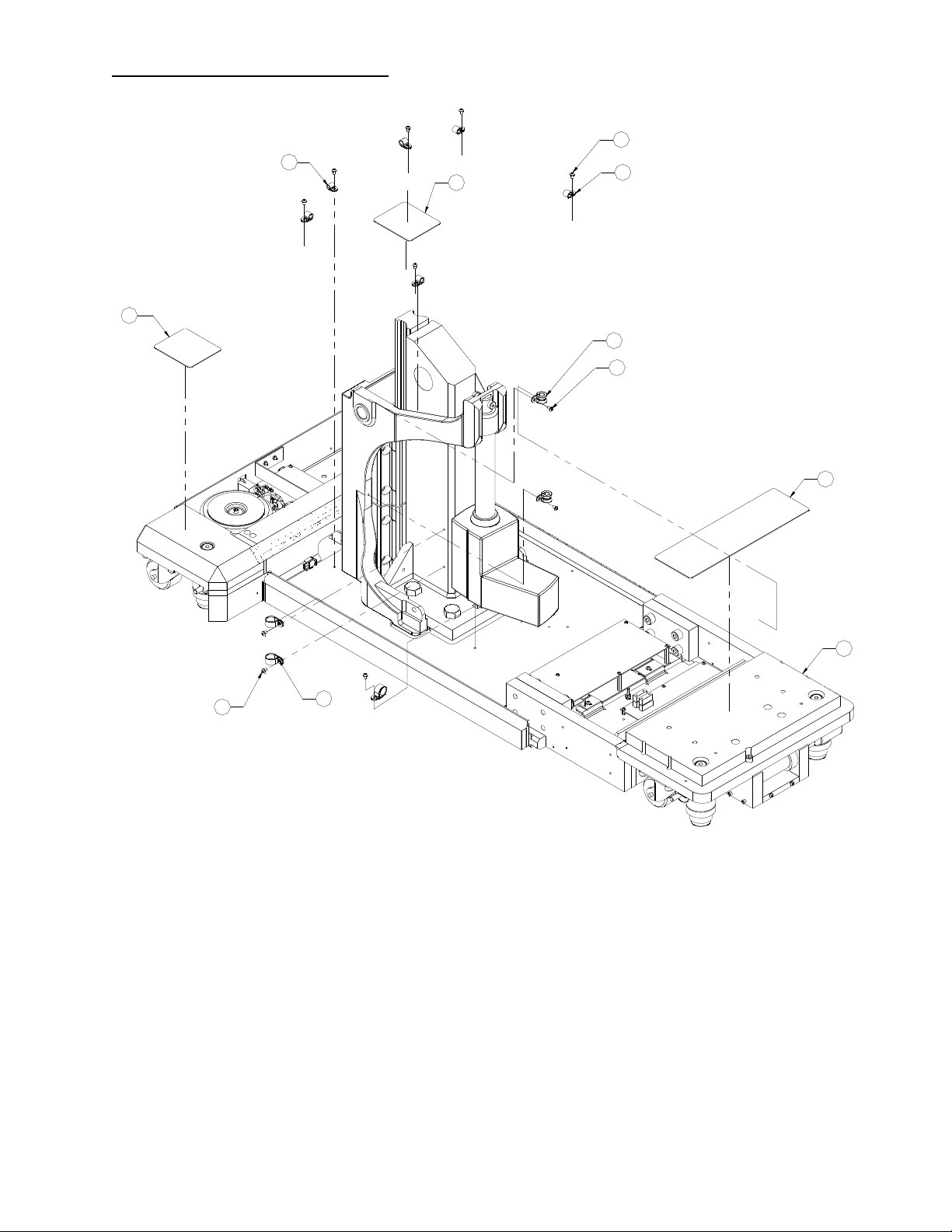
9.7 Base Assembly, Exploded View
87
78
50 6X
78
42 5X
43 2X
50 2X
78
1
503X
86 3X
6850 PROfx Maint. & Repair Manual NW0424 Rev. A
30
Page 32

9.8 X-Ring Assembly Exploded View
34
80 4X
445X
50
26
34
516X
80 4X
35
514X
714X
33
50
84
532X
43
50
42
21
47
23
433X
50 3X
33
823X
10
50 2X
65
62
42 2X
51 9X
75 3X
73 3X
45 5X
36
9
67
8
11
63 2X
22 2X
58
27
6850 PROfx Maint. & Repair Manual NW0424 Rev. A
31
Page 33

10.0 GLOSSARY OF TERMS
Basic assumptions of patient orientation on the tabletop: our glossary of terms and technical
procedures assume the patient is normally oriented with their head at the “head end of table”
(toward Control Panel) and their feet at the “foot end of table” (toward Leg Spars). The Hand
Control functions are oriented for this position only.
“Head end of table” refers to the end of the table where the power cord, "ON/OFF" power
switch, and Control Panel are located; otherwise referred to as the “pedestal end”.
“Foot end of table” refers to the opposite end of the table also referred to the “leg spar end".
“Control Panel” is a panel of buttons and lights located on the head end of the table.
“Pedestal” refers to the main column structure that supports the tabletop.
“Left side of the table” refers to the table as you stand at the head end of table.
This also corresponds to the Hand Control button labeled “LEFT LATERAL ROLL”.
“Right side of the table refers to the table as you stand at the head end of table.
This also corresponds to the Hand Control button labeled “RIGHT LATERAL ROLL”.
“Raise the table” refers to raising the height of the table.
This also corresponds to the Hand Control button labeled “HEIGHT UP”.
“Lower the table” refers to lowering the height of the table.
This also corresponds to the Hand Control button labeled “HEIGHT DOWN”.
“Raise the foot end of the table” refers to raising the height of the foot end of the tabletop or leg
spars. The corresponding Hand Control button is labeled “TREN” (Trendelenburg).
“Raise the head end of the table” refers to raising the height of the head end of the tabletop.
The corresponding Hand Control button is labeled “REV TREN” (Reverse Trendelenburg).
“Level the table” refers to leveling the tabletop regardless of height. The corresponding Hand
Control button is labeled “RETURN TO LEVEL”. Holding the “RETURN TO LEVEL” button
longer than approximately three seconds will also lower the tabletop to its lowest position.
"Lock the floor locks" refers to lowering the floor locks. The floor locks, when locked down,
will prevent the table from rolling and enable all other table functions. The corresponding Hand
Control button is "FLOOR LOCK" and the "FLOOR LOCK ON" light will illuminate or Control
Panel button is labeled “DOWN TO LOCK” and the green "LOCKED WHEN LIT" light will
illuminate.
“Unlock the floor locks” refers to rising the floor locks up 1/2-inch off the floor, allowing the
table to freely roll on its wheels. The corresponding Hand Control button is "FLOOR UNLOCK"
and the "FLOOR LOCK STOWED" light will illuminate or Control Panel button is labeled “UP
TO UNLOCK” and the amber "STOWED WHEN LIT" light will illuminate.
“Hospital Grade" outlet refers to a 120VAC outlet properly wired with earth ground: Neutral to
Common = 120VAC; Neutral to Ground = 120VAC; Common to Ground less than zero point
five (0.5) VAC.
6850 PROfx Maint. & Repair Manual NW0424 Rev. A
32
Page 34

11.0 OSI TECHNICAL SERVICE
11.1 Contact for Parts and Service:
For detailed repair information or to order replacement parts, call the OSI Technical Services
Department:
A Technical Services representative is available from 7AM-5PM PST, Monday through Friday.
Please leave a message before or after business hours.
Please state; your name, phone number, facility name and city, affected equipment model
number and nature of problem.
OSI Telephone: 800-777-4674
An e-mail message may be left anytime at techsvcs@osisosi.com or through the Technical
Service icon in our web site: www.osiosi.com.
To order Replacement Parts (RP):
If unable to identify part - telephone, fax or E-mail to Technical Service.
If part is known - telephone, fax or E-mail part number and description to Customer Service for
price and availability.
To place Replacement Parts (RP) order - telephone, fax or E-mail part number, description,
price, customer number and method of shipment to Customer Service with purchase order.
Indicate that order is for Replacement Parts (RP).
To return damaged parts (RGA):
Identify parts to be returned.
Telephone, fax or E-mail part number and description of parts for return to Customer Service for
Return Goods Authorization (RGA) number and Certificate of Disinfection.
Return ship parts with RGA number clearly marked on outside of package.
Clean (disinfect) parts prior to shipping.
To send a part or item for OSI to repair (RA):
If unable to identify part - call, fax or E-mail to Technical Service.
If part is known - telephone, fax or E-mail part number and description to Technical Service for
Repair Authorization (RA) number and Certificate of Disinfection.
Clean (disinfect) parts prior to shipping.
Ship part with RA number clearly marked on outside of package.
Part will be evaluated and customer will be contacted with the cost of repair.
After customer approval of repair cost, part will be repaired and return shipped to customer.
End
6850 PROfx Maint. & Repair Manual NW0424 Rev. A
33
 Loading...