

Page 1

ADVANCED CONTROL BASE
FOR THE
MODULAR TABLE SYSTEM
OWNER’S MANUAL
Model 5803
This manual is written in five
languages in the following order:
(en) English
(es) Spanish
(fr) French
(de) German
(it) Italian
MIZUHO OSI
30031 AHERN AVENUE UNION CITY, CA 94587
Bus: 510-429-1500 Toll Free: 800-777-4674 Fax: 510-429- 85 0 0
WWW.MIZUHOSI.COM ·
MIZUHOSI 2009 1 NW0498 Rev E
NEWHIPNEWS.COM · NEWSPINENEWS.COM
Page 2
IMPORTANT NOTICES
CAUTION: To ensure safe operation of the equipment, please READ THESE
INSTRUCTIONS COMPLETELY and keep this manual readily available for future
reference.
Carefully observe and comply with all warnings, cautions and instructions placed on the
equipment or described in this manual.
In this manual, the WARNING symbol is intended to alert the user to the presence
of important operation, maintenance, or safety instructions.
PROTECTION AGAINST ELECTRICAL SHOCK HAZARD:
This symbol indicates this equipment is an applied part, TYPE B in
accordance with IEC 60601-1 and is generally suitable for applications involving
external or internal contact with the patient, excluding the heart. The patient
circuit is connected to protective earth and this equipment should be connected
only to outlets with a protective earth ground.
This symbol
indicates the external stud that is at the same potential as the
equipment chassis. If the AC power cable is not connected to an outlet with a
protective earth ground, this external stud should be connected to a protective
earth ground.
WARNING:
Proper preoperative and intraoperative procedures must be followed to prevent
venous stasis and pooling, pressure sore development, neuropathy, improper
electro-surgical tissue grounding, hypotension and hypothermia.
WARNING:
It is important to note that a Jackson Spinal Surgery or Imaging Table Top used
on the model 5803 Advanced Control Base must have gimbals. Earlier versions
of these table tops do not have gimbals. Use of table tops without gimbals on the
5803 Advanced Control Base can result in damage to the table and the base.
WARNING:
Prior to attempting to use the Modular Table Base, one should carefully review
this owners manual and keep a copy on file for further reference. It is
recommended that one also view the appropriate sections of the Modular Table
System instructional video provided with the table top.
This device is to be used by trained personnel only.
MIZUHOSI 2009 NW0498 Rev E
2
Page 3

TABLE OF CONTENTS
1.0 INTRODUCTION..................................................................................................................................................5
1.1 General Description.........................................................................................................................................5
1.2 Specifications....................................................................................................................................................5
1.3 Shipping.............................................................................................................................................................5
1.4 Storage ..............................................................................................................................................................6
1.5 Acceptance & Transfer....................................................................................................................................6
1.6 Inspection and Transfer...................................................................................................................................6
2.0 GLOSSARY of TERMS......................................................................................................................................7
3.0 CONTROLS IDENTIFICATION.........................................................................................................................8
3.1 Base Orientation...............................................................................................................................................9
3.2 Model Number and Serial Number................................................................................................................9
4.0 BASIC OPERATION.........................................................................................................................................10
4.1 Casters.............................................................................................................................................................10
4.2 Hand Pendant.................................................................................................................................................11
4.3 5803 Advanced Base Controls..................................................................................................................... 13
4.3.1 Rotation Safety Lock ..................................................................................................................................13
4.3.2 180° Rotation Lock Indicator.....................................................................................................................14
4.3.3 Tilt Drive Status Indicator...........................................................................................................................14
4.4 Synchronizing The Lateral Tilt Function......................................................................................................15
4.5 Tabletop Coupling Procedure.......................................................................................................................17
4.6 Patient Transfer..............................................................................................................................................19
4.7 Table Top Coupling Procedure With Top In Place....................................................................................19
4.8 Patient Rotation..............................................................................................................................................20
4.9 Rotation Lock System....................................................................................................................................20
4.10 Rotation Procedure......................................................................................................................................20
4.11 Retracting The Base For Storage..............................................................................................................21
4.12 Table Top on the Base................................................................................................................................22
5.0 PRE-OPERATIONAL FUNCTION CHECK...................................................................................................23
6.0 CLEANING and MAINTENANCE...................................................................................................................24
6.1 Cleaning and Disinfecting.............................................................................................................................24
6.2 Lubrication.......................................................................................................................................................24
6.3 Preventative Maintenance ............................................................................................................................25
7.0 THE ELECTRICAL SYSTEM...........................................................................................................................26
7.1 Power Cord.....................................................................................................................................................26
7.2 ON/OFF Power/Circuit-Breaker Switch.......................................................................................................26
7.3 Power ON / Fault / Battery Status Lights....................................................................................................26
7.4 Battery Recharging........................................................................................................................................26
8.0 TROUBLESHOOTING......................................................................................................................................27
8.1 Electrical System............................................................................................................................................27
8.2 Functional Guide............................................................................................................................................28
9.0 REMOVAL and REPLACEMENT of COMPONENTS.................................................................................30
9.1 Head end Cover .............................................................................................................................................30
9.2 Foot End Cover...............................................................................................................................................31
9.3 Hand Pendant Module...................................................................................................................................31
9.4 Batteries...........................................................................................................................................................32
9.5 Power Supply Replacement.........................................................................................................................34
9.6 Controller Circuit Board Replacement.........................................................................................................34
9.7 On-Off Power Switch / Circuit Breaker Replacement...............................................................................35
9.8 Head End Assembly......................................................................................................................................35
9.9 Head End Tilt Motor.......................................................................................................................................35
9.10 Foot End Rotation Safety Lock Motor.......................................................................................................35
9.11 Head End or Foot End Column..................................................................................................................36
9.12 Retractable Center Beam...........................................................................................................................36
9.13 Casters ..........................................................................................................................................................36
MIZUHOSI 2009 NW0498 Rev E
3
Page 4

10.0 ADJUSTMENT of COMPONENTS...............................................................................................................37
HEAD END ............................................................................................................................................................37
10.1 Tilt Actuator Rod End Position...................................................................................................................37
10.2 180° Rotation Lock Sensor.........................................................................................................................37
10.3 Home & Tilt Left/Right Sensors.................................................................................................................. 38
10.4 Head end Slider Adjustment Procedure...................................................................................................39
10.5 Rotation Safety Lock....................................................................................................................................40
10.6 Rotation Safety Lock (Brake) “ON” Sensor Setting.................................................................................41
11.0 Mizuho OSI TECHNICAL SERVICE............................................................................................................42
11.1 Contact for Parts and Service....................................................................................................................42
11.2 Instant Support Value Package ................................................................................................................. 42
11.3 To order Replacement Parts (RP).............................................................................................................42
11.4 To return damaged parts (RGA)................................................................................................................42
11.5 To send a part for repair (RA)....................................................................................................................43
11.6 EC Authorized Representative...................................................................................................................43
11.7 Replacement / Spare Parts List.................................................................................................................44
11.8 Replacement Parts......................................................................................................................................45
11.9 INTERCONNECT DIAGRAM....................................................................................................................46
MIZUHOSI 2009 NW0498 Rev E
4
Page 5

1.0 INTRODUCTION
1.1 General Description
This manual describes the use, maintenance, and repair of the Modular Table System
(MTS) 5803 Advanced Control I-Base, DC (5803 Base). It is the primary component of
the system designed to support patients for a variety of surgical procedures. The 5803
Base is designed to hold a table top that will provide a patient support that is free of any
obstructions that might compete for space with a fluoroscopic C-Arm. There are five
procedure-specific table tops: Jackson Spinal, Radiolucent Imaging, Orthopedic
Trauma, Endourology and Maximum Access Lateral Top available for use on the MTS
Base.
1.2 Specifications
Maximum Patient Weight: Table top specific but not to exceed 500 lbs
Height Range of Base 34 - 48 inches (83.36 – 121 centimeters)
Trendelenburg Range 10 3
Reverse Trendelenburg 10° ±3°
Range
Powered Lateral Roll 25 3
Power Input (configurable)
o 100 VAC at 50/60 Hz
o 120 VAC at 60 Hz
o 230 VAC at 50 Hz
o internal battery power
Compatible Tabletops All MTS tops equipped with gimbals.
Maximum Length 102 inches (259 cm)
Retracted Length 64 inches (162 cm)
Width 32 inches (81 cm)
Maximum tilt torque 55 ft-lb
Maximum brake torque 93 ft-lb
Duty Cycle 4% or 2.5 minutes continuously per hour
1.3 Shipping
The 5803 Base must be shipped in a manner that prevents damage to its structural
elements, caster wheels, electronics, and operating controls. Contact with solid objects
in the environment must be prevented during shipment and storage, except at the four
casters. Banding for lateral constraint is to be limited to the base structure. Additionally,
banding of the head end assembly to prevent movement of the trolley is necessary. It is
also necessary to fully crate the 5803 Base to assure that no impact with foreign solid
objects will be made during transit. The 5803 Base is to be shipped in an environment
within the following limits:
Ambient temperature -4°F to 122°F (-20° C to +50° C)
Relative humidity from 10% to 100%, including condensation
Atmospheric pressure from 50 to 110 kPa.
MIZUHOSI 2009 NW0498 Rev E
5
Page 6

1.4 Storage
When not in use, store in a clean, dry environment with temperature between 32°F and
120°F (0° C to 49°C).
It is recommended that the 5803 Base be stowed with the power cord plugged into a
proper AC receptacle with the on/off power-switch “on” to assure batteries are fully
charged and ready for service.
If recharge is required, charge a minimum of 3 hours. A full charge should be
available after 18 hours.
1.5 Acceptance & Transfer
Upon receipt of your table, remove the table from the shipping crate following the
unpacking instructions. Visually inspect all surfaces for freight damage. Check each
caster for proper rolling operation.
NOTE: Any freight damage must be reported to the freight carrier immediately upon
delivery. It is the responsibility of the recipient to make freight damage claims.
1. Read the model/serial number identification label found at the head end of the base
(see figure 4) to confirm the serial number and the input power requirements.
2. Perform pre-op function check; see section 5.0.
1.6 Inspection and Transfer
Before use, inspect the device for possible damage, excessive wear or non-functioning
parts. Carefully inspect all critical, inaccessible areas, joints, electrical cords and all
movable parts for possible damage or non-function.
Damaged or defective products should not be used or processed. Contact your local
MIZUHO OSI sales representative for repair or replacement.
MIZUHOSI 2009 NW0498 Rev E
6
Page 7

2.0 GLOSSARY of TERMS
This glossary of terms and technical procedures assume the patient is oriented with
their head at the head end of table and their feet at the foot end of table. The hand
pendant functions are oriented for this position only.
Head end of base, indicates the end of the table where the power cord, "On-Off" switch,
and Control Panel are located.
Foot end of base, indicates the opposite end of the table.
Column, refers to one of two main column structures that support the tabletop.
Left side of the base, refers to the base as you stand at the head end of table.
Right side of the base, refers to the table as you stand at the front of column.
Raise the column, refers to raising the height of the column. This also corresponds to
Height Up.
Lower the column, refers to lowering the height of the column. This also corresponds to
Height Down.
Left lateral roll (tilt), refers to tilting the table top to the left when standing at the head
end of the base facing the foot end.
Right lateral roll (tilt), refers to tilting the table top to the right when standing at the head
end of the base facing the foot end.
Trendelenburg, refers to lowering the head end below the foot end.
Reverse trendelenburg, refers to lowering the foot end below the head end.
Hospital Grade, outlet refers to a 120VAC outlet properly wired with earth ground:
Neutral to Common = 120VAC; Neutral to Ground = 120VAC; Common to Ground less
than zero point five 0.5 VAC.
MIZUHOSI 2009 NW0498 Rev E
7
Page 8
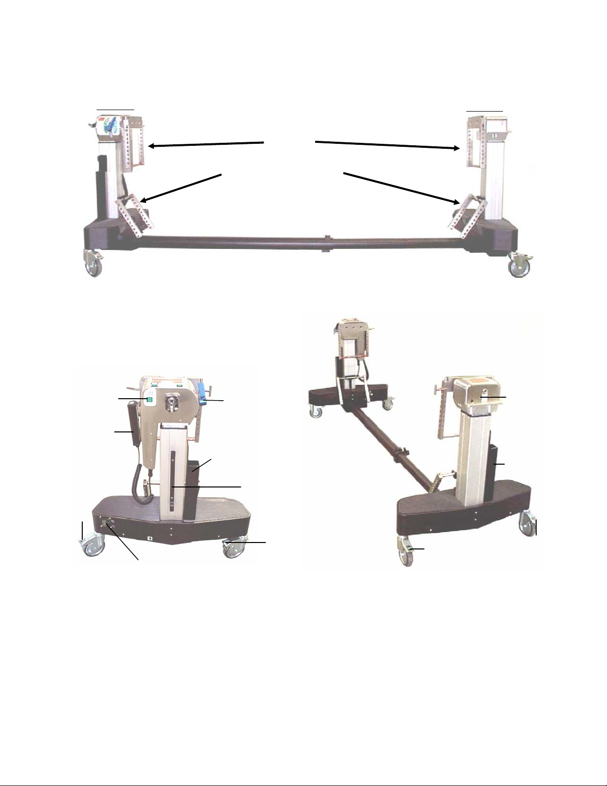
3.0 CONTROLS IDENTIFICATION
m
The major components of the 5803 Advanced Control Base are identified in the
following figures.
Head end
H-Frame
H-Frame in Storage Bracket
Foot End
Center Bea
Locking Caster
Figure 1: 5803 Advanced Control Base - Side View
Tilt Drive
Status Switch
Hand Pendant
Locking
Caster
Figure 2: 5803 Advanced Control Base - Head End View
On/Off Switch – Identification Label
180° Rotation
Lock
Quiver
T-Pin Storage
Power Cord
Storage Wrap
Locking
Caster
Retracting Lock Knob
Steer Caster
Traction Arc
Interlocking
Switch
Quiver
T-Pin Storage
Steer Caster
Figure 3: 5803 Advanced Control Base - Foot End View
Locking Caster
MIZUHOSI 2009 NW0498 Rev E
8
Page 9

3.1 Base Orientation
The control end of the base is considered the head end, and the opposite end is the foot
end. The right side of the base is the side to the operator’s right when standing at the
head end looking toward the foot end. The general nomenclature and orientation of the
base is shown in figure 1, 2 and 3. Refer to the appropriate owners manual supplied
with each table top for table top component Identification and more detailed information
about the use of each table top.
3.2 Model Number and Serial Number
The model number and serial number are printed on the Identification label located at
the head end base. This label is located to the right of the on/off switch as shown
below.
On/Off
Switch
“Battery Status”
“Fault”, & Power lights
Head end
Base
Out Side
Model/Serial
Number
Identification
Label
Figure 4: Head End; Base Outside
Power Cord
Plug In
Reset Button
Circuit Breaker
External Ground
Stud
Head end
Base
Beam Side
Figure 5: Head End; Base Beam Side
MIZUHOSI 2009 NW0498 Rev E
9
Page 10
4.0 BASIC OPERATION
The 5803 Advanced Control Base uses an external AC power source or internal,
rechargeable, battery power for operation. It uses AC power when plugged into a proper
AC receptacle and the on/off power-switch is in the “on” position. When not plugged in,
or AC power is lost, the 5803 Base will automatically switch over to internal battery
power. The batteries are automatically recharged whenever the 5803 Base is plugged
into an AC power source and the on/off power-switch is in the “on” position. Located
next to the on/off power-switch on the head end base (see figure 4) is the power on,
fault, and battery status lights.
WARNING:
When the power cord is removed and/or not plugged into an AC outlet, the
protective earth ground stud near the power entry module must be connected to
a proper earth ground during use.
WARNING:
All Locks must be engaged before a patient transfer is performed.
4.1 Casters
Each base is equipped with three (3) locking casters and one (1) steer caster. The
steer caster functions to allow the table to roll along a straight path when pushed from
the head end. The steer caster is located on the right side of the foot end. The steer
caster has a green label marked “Steer”. To lock the table base securely in place, it is
necessary to engage the lock on each of the four (4) casters.
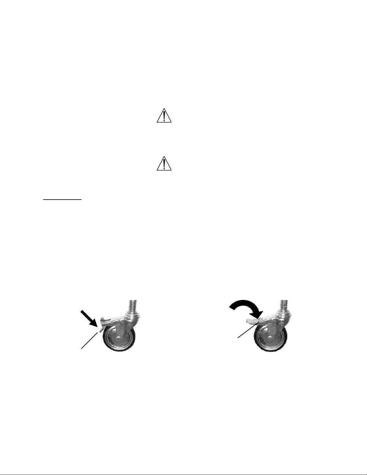
To lock a caster lock, step on the lock tab until you hear an audible click and the tab
remains in the down or locked position (see figure 6). To unlock the caster, push the
unlock button. When the unlock button is pressed, the tab will click back to the original
unlocked position (see figure 7).
To Lock
To Unlock
Lock
Tab
Unlock
Button
Figure 6: Locked Caster Figure 7: Unlocked Caster
MIZUHOSI 2009 NW0498 Rev E
10
Page 11
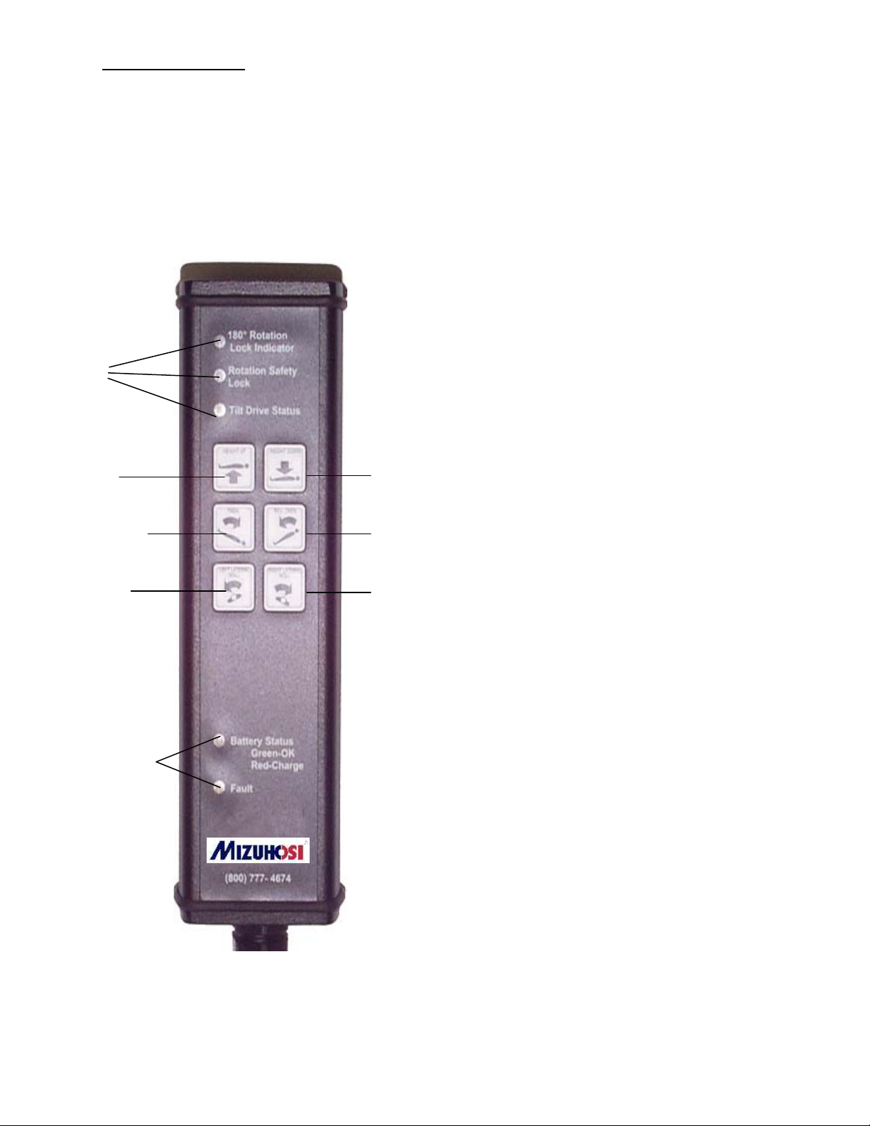
4.2 Hand Pendant
Each 5803 Advanced Control Base is equipped with a hand-held pendant, which is on a
storage bracket attached to the head end. The hand pendant allows the operator to
manipulate the table into trendelenburg, reverse trendelenburg, and lateral roll (tilt)
positions. The selected function will continue to operate until the button on the hand
pendant is released.
NOTE: It is recommended that a table top always be connected between the head and
foot ends when operating the powered controls.
Indicator
Lights
To raise the table, depress the
height up button on the left side of
the control with the arrow that points
in the “up” direction.
To lower the table, depress the
height down button on the right side
of the control with the arrow that
points in the “down” direction.
Height Up
Trendelenburg
Left Lateral
Roll (Tilt)
Indicator
Lights
Figure 8: Hand Pendant
Height
Down
Reverse
Trendelenburg
Right Lateral
Roll (Tilt)
To trendelenburg the table,
depress the button on the left with
the arrow that indicates foot up until
the desired trendelenburg angle is
achieved. This lowers the head end
column and raises the foot end
column simultaneously. If the table is
in a fully lowered position, only the
foot end will raise to achieve the
desired trendelenburg angle.
To reverse trendelenburg the
table, depress the button on the right
with the arrow that indicates foot
down until the desired reverse
trendelenburg angle is achieved.
This raises the head end column and
lowers the foot end column
simultaneously. If the table is in a
fully raised position, only the foot end
will lower to achieve the proper
reverse trendelenburg angle.
To laterally tilt to the left, depress
the left lateral roll button on the left
side of the control.
To laterally tilt to the right, depress
the right lateral roll button on the
right side of the control.
MIZUHOSI 2009 NW0498 Rev E
11
Page 12

NOTE: In the event a large traction arc 5855-13 is placed on the base, the tilt function
has been made inoperable. However in the event a small traction arc 5848-191 is
placed on the base, the tilt function is still operable.
Battery Status Light:
Green = OK
Red = Needs Recharge
Fault Indicator Light:
Electrical Fault
To unplug and re-attach the Hand Control:
At the end of the hand pendant coiled-cord is a black connector plug. Unscrew the
connector locking nut and pull the connector straight down out of the socket. To reattach, insert the connector into the socket with the notches on the connector lining up
with the slots on the socket. The connector locking nut must be tightened around the
socket to insure proper connection.
If the hand pendant is removed when table power is on, power must be switched off for
10 seconds and then back on after re-attaching the hand pendant for the hand pendant
to function (refer to section 8.0 for additional information).
MIZUHOSI 2009 NW0498 Rev E
12
Page 13

4.3 5803 Advanced Base Controls
The head end base of the 5803 Advanced Control Base is equipped with four indicator
lights (see figure 4). These lights are: 1) on/off AC power switch light, 2) power light, 3)
battery status light, and 4) fault light. Under normal AC operation, the on/off AC power
switch light and battery status light should be lit green and the fault light should be dark.
NOTE: If the fault light on hand pendant or base is lit, the 5803 Advanced Control Base
has detected a fault in the system. Determine fault before use (refer to sections 4.2 &
4.3).
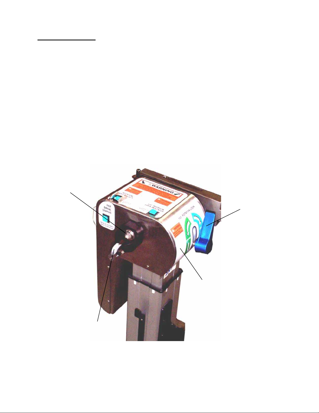
The head end pivot assembly of the 5803 Advanced Control Base is equipped with
three indicator lights. These lights are: 1) 180° rotation lock indicator light, 2) tilt drive
status light and 3) rotation safety lock indicator light. Verify that the rotation safety lock
switch is in the on position and the 180° rotation lock handle is in the locked position.
All three lights must be illuminated before a patient is transferred to the table. These
indicator lights are shown in figure 9.
3) Rotation Safety Lock
Lighted Switch
1) 180° Rotation Lock
Indicator Light
Crossbar
2) Tilt Drive Status
Indicator Light
Traction Pulley
180°° Rotation
Lock Lever (blue)
Figure 9: Head End Pivot Assembly Indicator Lights and Controls
4.3.1 Rotation Safety Lock
The rotation safety lock switch locks out the 180° rotation function. This feature
is designed to prevent unintended rotation of the table top. When the rotation
safety lock switch is illuminated, the table top can still be laterally tilted by
pressing the left or right lateral roll button on the hand pendant. The rotation
safety lock switch should be turned off only when a 180° rotation is to be
performed. If the rotation safety lock switch is not illuminated, press the rocker
switch to the on position.
MIZUHOSI 2009 NW0498 Rev E
13
Page 14

4.3.2 180° Rotation Lock Indicator
When illuminated, the 180° rotation lock indicator light indicates the lock is
engaged and the table cannot be rotated 180°. If the 180° rotation lock indicator
is not illuminated, turn the rotation lock lever clockwise until the light is
illuminated.
NOTE: If a 180° patient rotation is to be performed, the rotation lock lever should
be rotated counterclockwise approximately one half rotation past the point that
the rotation lock indicator light goes out. Rotating the lock lever to this point
lessens the drag of the friction control, thereby allowing the table tops to rotate
more freely during the rotation. If even less friction is desired, the lock lever may
be rotated further counterclockwise, as necessary. If more friction is desired,
rotate handle clockwise.
After the patient rotation is complete, rotate the rotation lock lever clockwise until
the rotation lock indicator light is illuminated.
WARNING:
When the rotation lock indicator light is not illuminated, the table top is
UNLOCKED regardless of how much the lock lever has been turned clockwise or
counterclockwise. Always turn the lock lever until the rotation lock indicator light
is illuminated after a 180° rotation.
4.3.3 Tilt Drive Status Indicator
The tilt drive status indicator light is illuminated when the powered lateral tilt drive
mechanism is in the center position of the +/- 25- lateral tilt range. If the tilt drive
status indicator is not illuminated, operate the lateral tilt function using the hand
pendant in the appropriate direction until the indicator is illuminated. The head
end crossbar should be horizontal when the tilt drive status indicator is
illuminated. If the head end crossbar is not horizontal, the internal power tilt
mechanism is out of synchronization with the crossbar. Refer to section 4.4
synchronizing the lateral tilt function to reset this function.
MIZUHOSI 2009 NW0498 Rev E
14
Page 15

4.4 Synchronizing The Lateral Tilt Function
Normally, the head end crossbar and tilt drive mechanism are synchronized so that the
tilt drive is in the middle of its travel range when the crossbar is level. It is possible for
the crossbar and tilt drive to become unsynchronized if the crossbar is rotated manually.
Also, the head end crossbar and foot end crossbar can become unsynchronized (not at
the same tilt angle) if a crossbar is rotated manually or the 5803 Advanced Control Base
is operated without a table top in place. The crossbars must be synchronized to each
other, as well as to the tilt drive mechanism.
WARNING:
Never attempt to attach a Table Top to the 5803 Advanced Control Base if the
head and foot end crossbars are not horizontal and level. Doing so may cause
damage to the table top or the tilt drive system.
To verify synchronization of the tilt drive and head end crossbar:
1. Confirm that the 180° rotation lock is engaged and Indicator light / switch illuminated.
2. Confirm that the rotation safety lock is engaged and Indicator light / switch
illuminated.
3. Use the hand pendant lateral roll buttons to rotate the head end crossbar until it is
level.
4. Confirm the tilt drive status indicator light illuminates (on hand pendant or head end
pivot assembly) indicating proper synchronization.
If the light will not illuminate, the head end crossbar and tilt drive are not
synchronized.
If the head end crossbar will not level using the hand pendant lateral roll buttons,
then the head end crossbar and tilt drive are not synchronized.
To re-synchronize the tilt drive and head end crossbar:
Different techniques are used depending on whether a table top is attached to the base
or not. Choose from the following cases.
Case 1: Table top is
coupled to the base
1. Confirm table top is attac hed to H-frame and securely locked in place with the T- pin.
No patient or load should be on table top.
2. Turn power switch on.
3. Turn off the rotation safety lock. The switch should not be illuminated.
4. Rotate the 180° rotation lock lever counter-clockwise until it is disengaged. Be
careful – this allows the table top to swing freely.
5. The tilt drive mechanism will automatically return to the middle of its range. While
this occurs, you will hear the tilt motor running, but the table top will only rotate a
little (if at all).
6. When the tilt motor stops, observe the tilt drive status light. If it is illuminated, then
the drive is in the middle of its travel range.
7. Verify that the head end and foot end crossbars are level.
8. Turn on the rotation safety lock. The indicator light should illuminate.
MIZUHOSI 2009 NW0498 Rev E
15
Page 16

9. Rotate the 180° rotation lock handle clockwise until it is engaged (lock indicator light
is illuminated).
10. The tilt drive is now synchronized to the crossbars, and the crossbars are
synchronized to each other.
Case 2: A table top is not coupled to the base
1. Turn power switch on.
2. Turn off the rotation safety lock. The switch should not be illuminated.
CAUTION: This allows the foot end crossbar to rotate freely; any load on the
crossbar can make it swing.
3. Rotate the 180° rotation lock lever counter-clockwise until it is disengaged.
CAUTION: This allows the head end crossbar to rotate freely; any load on the
crossbar can make it swing.
4. The tilt drive mechanism will automatically return to the middle of its range. While
this occurs, you will hear the tilt motor running, and the head end crossbar may
rotate.
5. When the tilt motor stops, observe the tilt drive status light. If it is illuminated, then
the tilt drive is in the middle of its travel range.
6. Manually level the head end crossbar.
7. Manually level the foot end crossbar.
8. Turn on the rotation safety lock switch. The switch should illuminate.
9. Rotate the 180° rotation lock lever, clockwise, until it is engaged (lock Indicator light
is illuminated).
10. The tilt drive is now synchronized to the crossbars and the crossbars are
synchronized to each other.
MIZUHOSI 2009 NW0498 Rev E
16
Page 17
4.5 Tabletop Coupling Procedure
k
The modular table tops may be interchanged and coupled to the 5803 Advanced
Control Base as needed to provide flexibility and specific procedural capability. Position
the 5803 Base and engage all four caster locks. When using trendelenburg with tilt,
only table tops with gimbals may be used with the 5803 Base.
Jackson
Spinal Top
Imaging Top
Gimbal Coupling
Device
Figure 10: Jackson Spinal Top & Radiolucent Imaging Top with Gimbal Mounting Assemblies.
WARNING:
Verify that the Jackson Spinal Top or the Imaging Top being used has gimbals.
Never attach a Jackson Spinal Top or Imaging Top to the 5803 Advanced Control
Base that does not have gimbals.
Crossbar
Drop Loc
Figure - T-Pin Assembly
Foot End
Mounting Stud
ON
Drop Lock
H-Frame
T-Pin
T-Pin
See detail
at left
Detail
Figure 11: H-Frame Installed - Foot End Column
H-Frame
H-Frame
Storage Bracket
MIZUHOSI 2009 NW0498 Rev E
17
Page 18
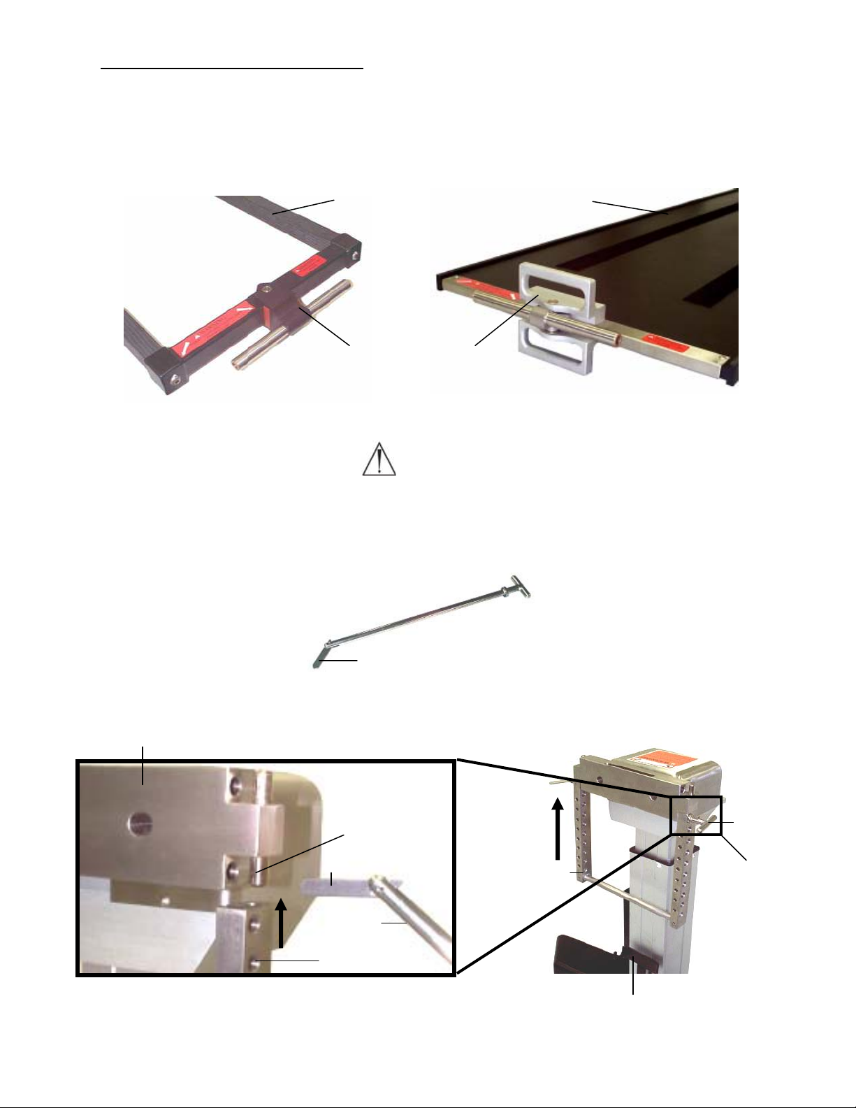
The following procedure assumes the foot end and head end columns do not have table
tops coupled in place. The coupling procedure is as follows:
1. Remove the H-frame from the H-frame storage bracket located on the foot end
column. Install the H-frame to the foot end crossbar and secure it with a T-pin. The
T-pins are stored in the T-pin quiver located adjacent to each column. The T-pin
must extend completely through both sides of the H-frame and the drop lock should
be in sight and pivot freely (see figure 11).
2. Remove the H-frame from the H-frame storage bracket located on the head end
column. Install the H-frame to head end crossbar and secure with a T-pin. The Tpins are stored in the T-pin quiver located adjacent to each column. The T-pin must
extend completely through both sides of the H-frame and the drop lock should be in
sight and pivot freely (see figure 11). The head end crossbar is attached to a sliding
assembly that adjusts superiorly and inferiorly to accommodate trendelenburg and
reverse trendelenburg length compensation. Fully retract the head end H-frame
against the head end column.
NOTE: If the H-frame is not aligned with the mounting studs, it may bind. Do not force
it. Lower the H-frame off and repeat until it mounts easily.
Head end
Sliding Assembly
T-Pin
ON
T-Pin Quiver
H-Frame
H-Frame Storage
Figure 12: Head End Pivot Assembly, H-Frame Installed
NOTE: Two people are required to complete the following sequence.
3. Select the appropriate mounting hole position on the H-frame to support the table
top. Hole selection will differ depending on the table top selected, the patients’ size
and the procedure to be performed. Further information on hole selection is available
in each of the table top owners manuals. On the foot end, align the table coupling
device with the hole in the H-frame and push the T-pin completely through.
MIZUHOSI 2009 NW0498 Rev E
18
Page 19

WARNING:
Verify that the T-pin is inserted through the H-frame, passes completely through
the table mounting tube, and through the opposite side of the H-frame and the Tpin drop lock is in sight and pivots freely.
4. To couple the head end of the table top, slide the H-frame and crossbar away from
the foot end as necessary to accommodate the length of the table top. Align the
holes in the head end H-frame and the table coupling device. Push the T-pin
completely through both sides of the H-frame and the coupling device making
certain that the drop lock is in sight and pivots freely. The head end and the foot end
of the table top are normally coupled at the same hole in the H-frame. The only
exception is when extreme trendelenburg is needed.
WARNING:
Failure to follow the above-prescribed procedures regarding securing the H-frame
to the crossbars and T-pin to the H-frame may result in the patient being dropped.
WARNING:
Prior to rotation, verify that all table coupling devices and H-frames are properly
installed and the T-pins pass completely through the H-frames and crossbars
with the drop lock in sight and pivots freely. Two (2) T-pins and drop locks should
be visible and checked at each end of the table.
4.6 Patient Transfer
Turn the power switch to on position. Prior to patient transfer, confirm that the desired
table top is secured by the H-frames and T-pins. Refer to specific table top coupling
procedure on page 16 of this Owners Manual for detailed information on attaching the
table tops. All three indicator lights should now be illuminated. If the tilt drive indicator
light is not lit, see synchronizing the lateral tilt function procedure on page 13.
WARNING:
If all three lights are not illuminated, do not use the base. Verify that the rotation
safety lock switch is in the on position and the 180° rotation lock lever is in the
locked position.
4.7 Table Top Coupling Procedure With Top In Place
When one table top is already coupled to the 5803 Advanced Control Base and you are
coupling a second top in order to change tops or facilitate a 180° tabletop rotation, the
slide mechanism of the head end sliding assembly will be held in a fixed position due to
the fixed length of the first top. This requires a different procedure to couple the second
top.
MIZUHOSI 2009 NW0498 Rev E
19
Page 20

With two people holding the second top,
1. Attach the head end H-frame as described above to the table top at the desired
mounting hole.
2. Position the second table top and attach the head end H-frame to the head end
crossbar.
3. Attach the foot end H-frame to the foot end crossbar surrounding the table top
coupling device.
4. Connect the table top coupling device to the foot end H-frame at the desired
mounting hole. Verify that the table top is coupled at the desired height at the head
end.
4.8 Patient Rotation
The MTS provides the capability of rotating a patient 180° to transfer the patient from
the supine to the prone position or vise-versa. This is a manually activated function. The
rotation is performed and controlled by the operating room personnel. Refer to the
Jackson Spinal Surgery and Imaging Table Owners Manual, Section 7.0 Rotation
Procedures for detailed instruction for a patient rotation.
NOTE: At least two people are required to hold and control the rotating motion of the
table tops. One additional person should be assigned to monitor the patient’s head
during the rotation.
4.9 Rotation Lock System
The 5803 Advanced Control Base is designed to engage the rotation safety lock
automatically whenever the on/off power switch is turned “OFF”. Automatic rotation
safety lock engagement ensures that the table top cannot unintentionally rotate laterally
without power.
4.10 Rotation Procedure
With an attendant at the head end of the table:
1. Patient is securely strapped to table system.
2. Release the 180° rotation lock by rotating the lever counterclockwise until the 180°
rotation lock indicator light goes out.
3. Advise the attendants holding the tabletops that the rotation safety lock is about to
be released.
4. Release the rotation safety lock by pressing the rocker switch to the off position.
Observe that the indicator light goes out.
5. Rotate the tabletops.
NOTE: The attendant performing the rotation must rotate the tabletops 180° toward
himself or herself without stopping until the complete 180° rotation is achieved.
After the rotation:
1. Immediately engage the rotation safety lock by pressing the rocker switch to the on
position and observe that the indicator light is illuminated.
2. Lock the 180° rotation lock by rotating the lever clockwise until the 180° rotation lock
indicator light is illuminated.
NOTE: The attendant performing the rotation may now release the table tops.
MIZUHOSI 2009 NW0498 Rev E
20
Page 21

4.11 Retracting The Base For Storage
The 5803 Advanced Control Base retracts for storage (refer to Section 1.2 for Length
and Width specifications).
To retract the base:
1. Lock the head end casters and unlock the foot end casters.
2. Loosen the retracting locking knob on the center beam (see figure 13).
NOTE: This knob will become completely separated from the base if rotated many
times.
3. Push the foot end of the base toward the head end of the base until the foot end is
retracted to its minimum length.
4. Tighten the locking knob.
Head end Foot End
Retract
Figure 13: Retracting the 5803 Advanced Control Base
Retracting
Lock Knob
MIZUHOSI 2009 NW0498 Rev E
21
Page 22

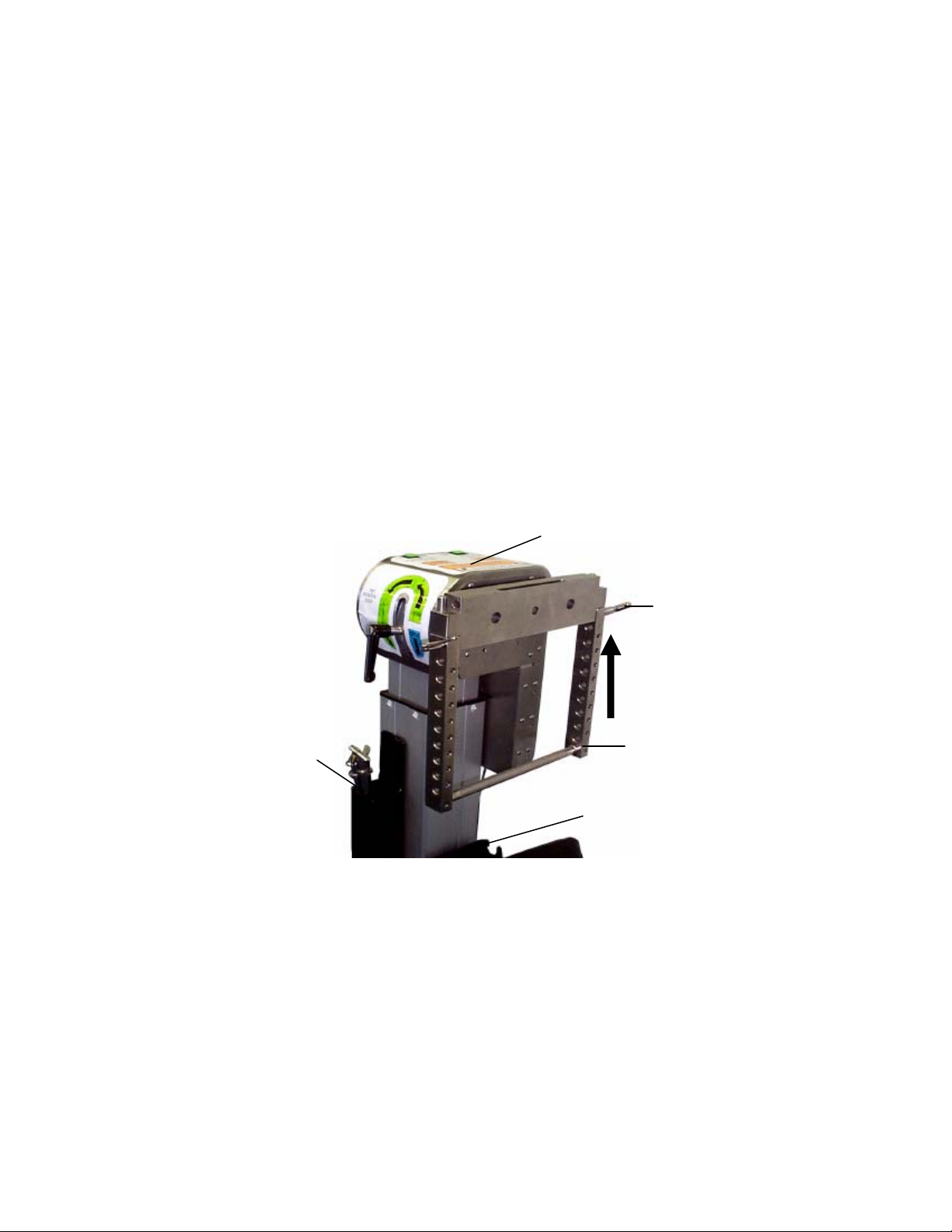
4.12 Table Top on the Base
It may be desirable to store a table top on a collapsed 5803 Advanced Control Base.
The table top storage bracket is an optional accessory and can be ordered from
customer service.
1. Remove the table top from H-frame.
2. Retract the base (refer to section 4.11).
3. If the head end H-frame is in the H-frame storage bracket, remove it and attach
to the head end crossbar.
4. Attach the table top storage bracket (optional accessory) to the foot end crossbar
using the gold handle.
5. Using the hand control, depress trendelenburg button which will raise the foot
end column to its highest position.
6. Place the coupling device of the table top in the head end H-frame storage
bracket.
7. Place the table top on the table top storage bracket on the foot end crossbar.
8. Unplug the power cord and store it on the cord wrap.
9. Push the foot end of the table toward the head end of the table until the foot end
is retracted to its minimum length.
The base and table top are now ready for storage.
MIZUHOSI 2009 NW0498 Rev E
22
Page 23

5.0 PRE-OPERATIONAL FUNCTION CHECK
After reading the basic operation (Section 4.0), perform all the steps in this procedure.
1. Plug in the hand pendant cable-connector into the receptacle located at the head
end column.
2. Plug the power cord into a hospital grade power outlet and flip the main on/of f power
switch to on. Verify the switch illuminates; this indicates power is applied to the table.
3. In succession, press and hold each of the six buttons on the hand pendant and
confirm the operation of the following functions:
3.1. Height up
3.2. Height down
3.3. Trendelenburg
3.4. Reverse trendelenburg
3.5. Tilt left
3.6. Tilt right
3.7. Engage the rotation safety lock (switch to on) and the 180° rotation locks (blue
handle clockwise, indicator light illuminates).
3.8. Release the rotation safety and 180° rotation locks.
3.9. Confirm head end and foot end crossbars are unlocked by rotating each one
complete revolution.
3.10. Re-engage both the rotation safety and 180° rotation locks.
3.11. Confirm head end and foot end crossbars are locked; both crossbars firmly
resist rotation.
3.12. Using the hand control, press and hold left lateral roll (TILT) button to end of
travel. Confirm the foot end crossbar rotates freely.
3.13. Using the hand pendant, press and hold right lateral roll (TILT) button to end of
travel. Confirm the foot end crossbar rotates freely.
Report any malfunction to your Mizuho OSI representative immediately.
MIZUHOSI 2009 NW0498 Rev E
23
Page 24

6.0 CLEANING and MAINTENANCE
6.1 Cleaning and Disinfecting
After completion of each surgery, wipe the 5803 Advanced Control Base with a
quaternary disinfectant. Dry the base completely.
NOTE: The head end and foot end columns of the 5803 Advanced Control Base are
not sealed, therefore:
Never pour any liquid directly onto the table.
Never allow any liquid to enter the extensile joint of the columns.
Never subject the 5803 Advanced Control Base to an equipment washing machine.
Failure to thoroughly dry any surface after cleaning and disinfecting may result in rust.
It is important to dry the base to prevent rusting. Rust formation can prematurely
shorten the useful life expectancy of the 5803 Base.
USE OF IODOPHORS WILL CAUSE STAINING:
Base Exterior:
Exterior surface should be regularly wiped clean with a mild detergent solution and
wiped dry with a soft lint-free cloth.
Care should be taken to avoid exposing the base to excessive moisture. Flooding,
fogging or steam cleaning is not recommended and will void any warranty.
Blood or other fluids, etc., if allowed to remain on the base for a long period of time,
will require special cleaning to remove. A 5% acetic acid solution or white vinegar
and water solution is especially good for this purpose.
Cleaning with a good commercial cleaning compound, such as stainless steel Magic
or acme white finish, and then buffing the surface by hand can correct staining and
discoloration of plated or stainless steel surfaces.
To dis infect exterior surface use a quaternary ammonium or similar type disinfectant
compound according to manufacturer's directions for use. Wipe dry with a soft lintfree cloth.
Casters should be cleaned and disinfected in the same manner as base exterior.
6.2 Lubrication
Base Exterior:
Following a thorough cleaning and decontamination of the base, silic one lubricant spray
may be used on most of the exposed inner head and foot columns and inner retractable
beam. No other lubrication is necessary.
Base Interior:
All of the internal moving parts of the 5803 base receive factory lubrication which, under
normal use, provides lubrication for the life of the equipment.
MIZUHOSI 2009 NW0498 Rev E
24
Page 25

6.3 Preventative Maintenance
Contact Mizuho OSI Technical Service for a complete Preventative Maintenance
Checklist.
For detailed repair information or to order replacement parts, call or contact via the web
the Mizuho OSI technical services department
1-800-777-4674 Extension 2
techsvcs@mizuhosi.com
www.mizuhosi.com
Technical services is available from 7am – 5pm PST Monday – Friday. Please leave a
message at the extension after normal business hours.
MIZUHOSI 2009 NW0498 Rev E
25
Page 26

7.0 THE ELECTRICAL SYSTEM
7.1 Power Cord
The base is equipped with a standard EIC power cord with the appropriate 120 VAC
hospital grade connector (100 VAC & 230 VAC versions do not include the power
connector).
7.2 ON/OFF Power/Circuit-Breaker Switch
An on/off power switch is at the head end of the base. This switch also serves as a
circuit breaker and in the event of an overload condition this switch will trip off. To reset,
push to the off position and then the on position. Next to it a green power on light
illuminates indicating that the base power is on.
NOTE: Determine the source of the overload prior to resetting this switch.
7.3 Power ON / Fault / Battery Status Lights
Next to the on/off power switch is a small panel of three lights:
Green = Power on (AC power or battery power).
Red = Fault light (Electrical fault, determine source of fault prior to using table).
White = Battery status.
o When illuminated Green = installed properly and charged
o When illuminated Red = recharging required
7.4 Battery Recharging
The batteries in the 5803 Base are automatically charged whenever the table is in an
operational condition (plugged into AC power source and on/off power switch in the on
position). No additional procedures are needed to assure maintenance of the batteries.
The battery status lamp, next to the on/off power switch on the head end base casting,
indicates battery charge condition. If lit, the red battery status lamp indicates that the
batteries require recharging and the table must be plugged into an AC outlet. If the
battery status lamp remains illuminated red after three (3) hours, do not attempt to
operate the base under battery power and call for service (the 5803 Base should remain
functional under AC power). It is recommended that, prior to use, the 5803 Base be
plugged into a proper AC receptacle with the on/off switch in the on position for a
minimum of three (3) hours to ensure that the batteries are fully charged.
MIZUHOSI 2009 NW0498 Rev E
26
Page 27

8.0 TROUBLESHOOTING
8.1 Electrical System
In the advent of a base malfunction, the first item to investigate is the input power. Be
certain that the power cord is plugged into a live electrical outlet and the power switch is
switched on. A green "Power On" light illuminates indicates this.
WARNING:
Before removing any sheet metal covers the base must be turned off and
unplugged. Dangerous high voltage may be present in the circuitry under the
covers. Only trained technicians should perform this task.
SYMPTOM INSPECT ACTION
No column function
either end.
No column function
Head end
No column function
Foot end
Rotation friction control
won’t stop Rotation-Head end
Or Foot End.
Caster won’t lock/unlock Check caster for damage. Replace caster.
Check power.
Check that circuit breaker (light is
green).
Check hand pendant module and
cord.
Check electrical connector at
base of head or foot end Column.
Check hand pendant.
Check electrical connector at
base of head end column.
Check hand pendant module and
cord. Check electrical connector
at the base of foot end column.
Tighten lever to max. Check
brake band.
Plug in.
Reset breaker, turn on.
Plug in connector.
Plug in connector.
Plug in connector.
Adjust brake tension.
Adjust handle to proper range.
Replace if necessary.
MIZUHOSI 2009 NW0498 Rev E
27
Page 28

8.2 Functional Guide
FUNCTION GUIDE
Command: Result: If not, determine if
(Hand pendant) height up Both columns up
Height down Both columns down Same as for Height Up
Base power is off.
Power to PC board is not
connected.
Hand pendant is non-operative,
or not plugged in.
Cable from PC board to column
is not connected, or has failed.
If none of these are the problem
then the column or the PC board
has failed.
Trendelenburg Head end column down and foot
end column up
Reverse trendelenburg Foot end column down and head
end column up
Lateral roll (tilt) left or right
w/rotation safety lock switch off
Rotation safety lock switch off Brake releases
Tilt motor drives
Same as for Height Up
Same as for Height Up
Base power is off
Power supply is not operating
correctly
Power to PC board is not
connected
Hand pendant is non-operative
Hand pendant is not plugged in
PC board is non-operative
Cabling is not connected or has
failed
Tilt motor has failed, or brake-on
sensor is closed
Brake-on sense wire is shorted
Either limit switch has failed.
Either limit switch is open
Limit switch wiring is
disconnected
Base power is off
Power to PC board is not
connected
Power supply is not operating
Cable from PC board to column
is not connected
Cable to column has failed.
Brake off switch has failed
Wire connection to switch has
failed.
Traction arc switch closed
Traction arc switch wiring
shorted
Limit switch has failed
Mechanical error
MIZUHOSI 2009 NW0498 Rev E
28
Page 29

Rotation safety lock switch on Brake engages
Same as rotation safety lock
switch off.
Also verify switch, wiring, and
mounting of brake on sensor if
brake is weak, brake force
adjustment is incorrect
Lateral roll (tilt) left of right w/
rotation safety lock switch on
Release lateral roll (tilt) button Tilt motor ceases; brake engages
Release button. (all functions
except tilt when rocker switch is
on)
Traction arc switch closed
Lateral roll (tilt) left or right
Rotation safety lock switch off Brake motor disabled Same.
Handle loose Tilt motor drives until tilt drive
Brake releases; tilt motor drives
Immediate cessation of above.
No additional function
Tilt motor disabled, brake motor
disabled
status indicator lights
Same as tilt with rocker switch
off
Additionally: brake motor faulty
or wiring not connected
Hand pendant has failed, PC
board has failed
Same as for tilt w/rocker on
Hand pendant has failed
PC board has failed
Faulty switch,
broken wiring connection,
switch adjustment incorrect,
PC board has failed
Power off
Power to PC board not
connected
Power supply non-op, PC board
non-op
Cable from PC board to tilt motor
not connected
Tilt motor non-op
Home sensor has failed
Home sensor wiring shorted
Sensor misadjusted,
1/r sensor has failed, 1/r sensor
wiring shorted or disconnected
Sensor misadjusted
Lock sensor has failed
Lock sensor wiring disconnected
Traction arc switch closed
Traction arc switch wiring shorted
Rotation safety lock switch on.
Foot end crossbar tilted left or
right
Rotation safety lock off.
Power down
MIZUHOSI 2009 NW0498 Rev E
Tilt left or right disabled
Brake engages. LED turns on for
15-25 seconds later, LED off
29
Tilt left or right limit switch has
failed
Wiring disconnected
PC board has failed
Motor has failed
Wiring to motor disconnected
LED has failed; wiring
disconnected
PC board has failed
No battery power
Page 30
9.0 REMOVAL and REPLACEMENT of COMPONENTS
9.1 Head end Cover
1. Switch off the base at the circuit breaker and disconnect the power cord from the
source. Allow 45 seconds for discharge.
NOTE: Hand pendant backlights will go dark.
2. Disconnect hand pendant.
3. Remove 1st external retaining ring. Remove traction pulley assembly. Remove 2nd
retaining ring.
4. Remove 180° Rotation lock handle by rotating it counterclockwise until it is free.
5. Using a small screwdriver, pry out 180° indicator light to prevent damage.
6. Remove the cover screws on both sides of the cover except the lower screws.
7. Remove lower screws on both sides of the cover, and remove head end cover inside
panel.
8. Carefully slide the cover away from the base, along the tilt axis.
Caution: Wires still connect the switches and lights on the cover to the base.
Disconnect 16 pin connector.
External retaining ring
180°Rotation Lock
Handle
Head End Cover
Traction Pulley Assy
Figure 14: Head End Cover Removal
MIZUHOSI 2009 NW0498 Rev E
30
Page 31

9.2 Foot End Cover
1. Switch off the base at the circuit breaker and disconnect the power cord from the
source.
2. Remove the foot end base covers.
3. Disconnect the negative wires at the battery terminals.
4. Remove the foot end cover screws.
5. Carefully lift foot end cover up and off.
Screws
Foot End Base Cover
Screws
Figure 15: Foot End Cover Removal
9.3 Hand Pendant Module
1. Switch off the base at the circuit breaker and disconnect the power cord from the
source.
2. Unscrew hand pendant cord-connector from base receptacle.
3. Unplug hand pendant cord connector from the base.
MIZUHOSI 2009 NW0498 Rev E
31
Page 32

9.4 Batteries
WARNING:
Improperly installed batteries can leak, causing equipment damage or injury. See
photo below to assure correct installation of replacement batteries.
1. Rechargeable lead-acid batteries contain toxic materials
. Batteries should be fully
discharged prior to handling, or the terminals should be isolated to prevent
accidental discharge.
2. Batteries contain sulfuric acid. In the event of a leak in the battery or fire, dilute
spilled fluid with water. In case of skin contact, wash areas with water. In the event
of eye contact, flush eyes with water for 15 minutes and consult a physician
immediately.
3. Batteries should only be replaced with Mizuho OSI approved parts. Contact Mizuho
OSI to obtain correct replacement batteries.
4. Incorrectly connected batteries can caus e damage to equipment or injury. Bridging
(shorting) of battery terminals can cause explosion of the battery or fire.
5. Do not attempt to connect AC power to the 5803 Base until correct battery
connection is confirmed.
6. Always dispose of batteries properly. Do not incinerate batteries. Do not place
rechargeable 12V batteries into a metal trashcan, toolbox, drawer or parts bin.
7. Always take the following precautions when removing the battery compartment
covers:
Remove metal jewelry and wristwatches when in proximity to batteries.
Always cover at least one terminal of each battery with insulating material if
connectors are removed.
Use caution when employing metal tools in proximity to batteries. Metal tools
create circuit bridges (electrical shorts) upon contact. When possible, use tools
with insulated handles and ends.
Never place anything on top of batteries, whether batteries are mounted or
removed from product.
MIZUHOSI 2009 NW0498 Rev E
32
Page 33

Battery Charging and Inspection
r
Charge for minimum three (3) hours (Power cord plugged into power source and on/off
power-switch “ON”). If battery fails to hold a charge it should be replaced. Replace only
with identical type and size battery. Replace both batteries at the same time. Batteries
should be replaced once every five (5) years. Whenever the battery cover is opened,
check battery for signs of corrosion. Battery terminals should be clean and free from
corrosion, oil, grease, dirt, or other contaminants.
Battery Mizuho OSI ordering number: NV0801, failure to use an approved Mizuho OSI
battery terminates warranty.
Negative
Te
minal
Jumper
Wire
Positive
Terminal
Connection wires
to columns
Battery “B”
Battery “A”
Figure 16: Battery Placement
Battery Removal
1. Switch on/off power-switch to off, disconnect the power cord from power source (AC
outlet).
2. Remove the foot end base covers.
3. Disconnect the wires at the battery terminals. Cover at least one terminal of each
battery with insulating material.
4. Carefully lift batteries out of base.
Battery Replacement
1. Place replacement batteries in base as shown.
2. Install adhesive-backed loop closure (Velcro).
3. Attach battery wires as shown:
Red wire to positive terminal of battery “A”.
Jumper wire from battery “A” to battery “B”.
Black wire to negative terminal of battery “B”.
Batteries must be properly disposed of, and in accordance with domestic and
international standards and requirements.
MIZUHOSI 2009 NW0498 Rev E
33
Page 34

Battery Function Check
1. Verify power cord is disconnected from power source (AC outlet).
2. Turn on/off power-switch to “ON” (utilizing battery power).
3. Verify all hand pendant lights illuminate on and off sequentially.
4. Verify hand pendant and base panel battery status lights:
Green = batteries installed correctly and charged.
Red = batteries need charging.
5. Fault Light on and battery status light red = batteries not connected properly, or
completely discharged. Turn on/off power-switch “OFF” immediately and check:
Batteries connected properly.
Batteries have been charged.
Repeat test to verify that all lights on hand pendant illuminate on and off
sequentially and battery fault light is dark. If not, contact Mizuho OSI technical
service.
9.5 Power Supply Replacement
1. Switch off the base at the circuit breaker and disconnect the power cord from the
source.
2. Remove the 10-32 screws holding the input plate and circuit breaker plates to the
cover.
3. Remove the head end base covers.
4. Disconnect the negative battery wire.
5. Disconnect all cables from power supply and line filter. Remove transformer wires
from power entry module.
6. Remove the three power supply tray assembly mounting screws and remove tray
assembly.
7. Install replacement in the reverse order.
9.6 Controller Circuit Board Replacement
1. Switch off the base at the circuit breaker and disconnect the power cord from the
source.
2. Remove the 10-32 screws holding the input plate and circuit breaker plates to the
head end base covers.
3. Remove the head end base covers.
4. Disconnect the negative battery wire.
5. Disconnect all cables from controller circuit board
6. Remove the three 10-32 screws mounting the controller circuit board tray and
remove tray assembly.
7. Install replacement in the reverse order.
MIZUHOSI 2009 NW0498 Rev E
34
Page 35

9.7 On-Off Power Switch / Circuit Breaker Replacement
1. Switch off the base at the circuit breaker and disconnect the power cord from the
source.
2. Remove the 10-32 screws holding the input plate and circuit breaker plates to the
head end base covers.
3. Remove the head end base covers.
4. Disconnect the negative battery wire.
5. Disconnect the wires from circuit beaker / on-off switch terminals.
6. Remove the circuit beaker / on-off switch.
7. Install replacement in the reverse order.
9.8 Head End Assembly
1. Switch off the base at the circuit breaker and disconnect the power cord from the
source.
2. Remove the foot end base covers and disconnect the negative wire at a battery
terminal.
3. Remove the 180° Rotation lock handle.
4. Remove gr ip ring from crossbar shaft and slide the traction pulley bracket, from the
shaft.
5. Remove the 8-32 screws from rear of cover.
6. Remove the 2 screws from the front cover and slide inside cover down and away.
Disconnect the electrical cable attached to the cover.
7. Remove the remaining screw at the front cover, and take the cover off by rotating it
to the right.
8. Remove the ground wire screw.
9. Disconnect the electrical cable at the top of the column.
10. Remove the 10-32 screw underneath of the trolley in the groove at front.
11. Slide the head end assembly away from you and remove it from base.
12. Install replacement in the reverse order.
9.9 Head End Tilt Motor
1. Disconnect the motor wire from the wire harness.
2. Remove the E-ring from the pivot axle at the actuator rod joint end.
3. Slide the pivot axle out of the assembly.
4. Loosen and remove the shoulder screw (or E-rings on newer tables) at the base of
the actuators and remove the actuator.
9.10 Foot End Rotation Safety Lock Motor
1. Remove the shoulder screws holding the actuator to the brake pivot arm, and foot
pivot base.
2. Install in reverse order.
3. Adjust rotation safety lock (refer to rotation safety lock adjustment).
MIZUHOSI 2009 NW0498 Rev E
35
Page 36

9.11 Head End or Foot End Column
1. Remove any tabletop and H-frame(s).
2. Switch off the base at the circuit breaker and disconnect the power cord from the
source.
3. Remove the foot end base covers and disc onnect the negative wires at the battery
terminals.
4. Remove the foot end base cover by removing the mounting screws.
5. Remove the head end assembly or foot end.
6. Remove head end base cover: Remove the 10-32 screws holding the input plate
and circuit breaker plates to the head end base covers. Remove cover.
7. Remove foot end base cover: Remove the 10-32 screws holding the cover. Remove
cover.
8. Unplug the connectors at the base of each head end and foot end column.
9. Remove four socket head screws attaching the column to the retractable beam.
10. Lift out of the base the column.
11. Install replacement in the reverse order.
12. Adjust rotation safety lock per rotation safety lock adjustment.
NOTE: Before tightening the mounting screws upon installation stand the base upright
and attach a tabletop between the head end and foot end crossbar. With the screws
loose, rotate the top slowly several times to align the head end and foot ends. Reach
under the head end and foot end base and tighten the mounting screws before
removing the tabletop.
9.12 Retractable Center Beam
1. Remove any tabletop and H-frame.
2. Switch off the base at the circuit breaker and disconnect the power cord from the
source.
3. Remove the foot end base covers and disconnect the negative wire at a battery
terminal.
4. Remove head end covers.
5. Unplug beam cables.
6. Remove the head and foot columns.
7. Remove the ¼-20 inch screws attaching the beam to head end and foot end bases.
8. Remove the center beam.
9. Install replacement in the reverse order.
9.13 Casters
1. Remove the ½-inch bolt from the outside of the base plate.
MIZUHOSI 2009 NW0498 Rev E
36
Page 37

10.0 ADJUSTMENT of COMPONENTS
HEAD END
10.1 Tilt Actuator Rod End Position
1. Loosen lock nut on actuator rod end.
2. Rotate actuator rod until six threads are showing on the rod end.
3. Tighten lock nut.
4. Disconnect the actuator from the base wiring and connect an external power
controller to the actuator.
5. Drive the tilt mechanism all the way right (actuator ex tended). Watch for clearance
between the actuator rod and the pillow block at the end of actuator travel.
6. If the actuator rod touches the pillow block, re-loosen the locknut and turn the
actuator rod as many turns as necessary to ensure clearance. Retighten the rod
end.
7. Once complete, disconnect the tilt actuator from the external controller and connect
to the base wiring.
10.2 180° Rotation Lock Sensor
1. Remove the blue 180° rotation lock handle.
2. Remove head end cover per procedure; do not unplug electrical connector, hang
cover on table base power cord storage bracket.
3. Loosen 8-32 button head screw securing the 180° rotation sensor ( micro switch)
mounting bracket. This is mounted just to the left of the blue 180° rotation lock
handle (see figure 17).
4. Tighten the blue 180° rotation lock handle until rotating crossbar resists 95 ft/lbs
of rotational force in both directions using torque wrench and rotational test bar
(p/n T5890-21/23).
5. Adjust the 180° rotation sensor (micro switch) mounting bracket until the micro
switch clicks on. The "180° Rotation lock indicator" light should be illuminated
blue. Tighten 8-32 button head screw.
6. Test by unscrewing 180° Rotation lock handle until "180° Rotation lock indicator"
goes out. Retighten 180° Rotation lock handle until "180° Rotation lock Indicator"
lights.
7. Retest that rotating crossbar resists 95 ft/lbs of rotational force in both directions
using torque wrench and rotation test bar.
8. If test fails, repeat adjustment procedure.
9. If test passes continue.
10. Install covers per procedure.
11. Install "180° Rotation lock" handle and tighten until "180° Rotation lock indicator"
light illuminates blue.
12. Retest that rotating crossbar resists 95 ft/lbs of rotational force in both directions
using torque wrench and rotation test bar P/N T5890-21-23
13. If test fails, repeat adjustment procedure.
14. If test passes adjustment is complete.
MIZUHOSI 2009 NW0498 Rev E
37
Page 38

10.3 Home & Tilt Left/Right Sensors
1. Turn the base power on.
2. Tighten the 180° Rotation lock handle, and make sure that the indicator light is lit.
3. Using the hand pendant, drive the tilt mechanism to the right.
4. Loosen the 6-32 cap head screw beneath the sensor bracket and move the bracket
closer to the pillow block until the left/right sensor switch clicks.
5. Using the hand pendant, drive the tilt mechanism to the left. Stop when the home
sensor clicks. The indicator light should light up to confirm that the tilt drive is at
home.
6. Tighten the 6-32 cap head screw.
7. Using the hand pendant, drive the tilt mechanism to the right for about three
seconds.
8. Loosen the 180° Rotat ion lock handle. The tilt mechanism should drive to the center
and stop.
9. If it drives towards the center but stops before true level, the sensor switch is too
close to the pillow block. Tighten the 180° Rotation lock handle. Loosen the 6-32
cap head screw beneath the sensor bracket and move the bracket away from the
pillow block slightly. Re-tighten the 6-32. Check this readjustment by repeating
steps.
10. If it drives to the center but does not stop, either rocking back and forth or continuing
past lever, the sensor switch is too far from the pillow block slightly. Re-tighten the
6-32 screw. Check this readjustment by repeating steps.
11. If it does not drive at all when the 180° Rotation lock handle is loosened, there is an
electronic fault in the base. Check the wiring to the head end, and if this does not
alter the condition of the base, replace the controller PC board.
Sensor Switch
and Bracket
180° Rotation
Lock Handle
Figure 17: 180° Rotation Lock Indicator Light Limit Switch and Lock Handle
MIZUHOSI 2009 NW0498 Rev E
38
Page 39

10.4 Head end Slider Adjustment Procedure
Overview:
With one of the Mizuho OSI modular (interchangeable) table tops attached to the 5803
Advanced Control Base, in-line movement of the head end slider (or trolley assembly) is
required to accommodate trendelenburg and reverse trendelenburg positioning.
Periodic adjustment may be needed to maintain proper friction of movement.
Tools Required:
Hex (Allen) Key, 5/64-inch
Force Gauge, to 25-pounds pushing force.
Procedure:
1. Turn on/off power switch to off, disconnect power cord from power source (AC wall
outlet), allow 30 seconds for discharge.
2. Remove head end pivot assembly cover per procedure.
3. Some models may have a set screw installed in front of the spring plunger. This
screw must be removed prior to adjustment. Using 5/64-inch hex key, adjust Slider
spring plunger (shown below) as needed.
4. Using force gauge pushing on rotating crossbar, verify head end slider assembly
(without any top attached) moves in-line to its stops, in both directions, uniformly,
with 20 to 25 pounds of force applied.
Figure 18: Head End Pivot Assembly, Left Side (cover removed)
MIZUHOSI 2009 NW0498 Rev E
39
Page 40

FOOT END
10.5 Rotation Safety Lock
As the safety lock wears, adjustment may be required to achieve complete locking. The
adjustment for this is as follows:
1. The 5803 Advanced Control Base should be upright.
2. Supply power to the base and turn the circuit breaker on.
3. Remove the foot end cover.
4. If the sensor is not indicating that the rotation safety lock is on when crossbar is
secure, loosen the lock nut by one turn, then turn the adjustment setscrew counter
clockwise, while maintaining the setscrew position, and tighten the lock nut. Verify
operation of the rotation safety lock by turning it off and then on again.
5. If the crossbar is not adequately secure when the sensor indicat es that the rotation
safety lock is on, loosen the lock nut and turn the adjustment setscrew clockwise.
Then, while maintaining the setscrew orientation, tighten the lock nut. Verify
operation of the rotation safety lock by turning it off and back on again.
6. The crossbar is secure when it resists 93 foot-pounds of torque without slippage,
using torque wrench and rotation test bar P/N 5890-21-23.
7. Replace the cover.
Crossbar
Adjustment Setscrew
Lock Nut
Figure 19: Foot End Assembly
MIZUHOSI 2009 NW0498 Rev E
40
Page 41

10.6 Rotation Safety Lock (Brake) “ON” Sensor Setting
1. Remove the foot end base covers.
2. Disconnect the battery wire.
3. Turn off the rotation safety lock switch on the head end cover.
4. Supply power to the base and turn the circuit breaker on. Verify brake off sensor is
closed. If it is not, the system may have an electronic fault.
5. Back out the setscrew that locates the brake clamp all the way (see figure 18
adjustment setscrew).
6. Turn off the power to the base (either unplug or turn off the circuit breaker). Wait
until all the system lights go out.
7. Locate the brake on sensor. Loosen the screw that holds the mount plate for the
sensor to the brake lever.
8. Set the sensor all the way away from the motor housing. Snug the screw.
9. Restore power to the base (plug back in and turn on the circuit breaker).
10. Turn the rotation safety lock switch on; the brake motor will drive upward until
locked. If it does not drive up, the system has an electronic fault. The fault light will
be lit due to improper switch adjustment. Ignore.
11. Loosen the sensor bracket. Push the sensor body closer to the motor housing until
a click can be heard. Re-snug the mount screw.
12. Turn the system power on.
13. Turn the rotation safety lock switch off; the brake motor will drive down until the
brake off sensor switch closes.
14. Turn the rotation safety lock switch on.
15. Verify that the switch is closed when the motor stops.
16. Reconnect the battery wire.
17. Replace the cover underneath the foot end base casting.
MIZUHOSI 2009 NW0498 Rev E
41
Page 42

11.0 Mizuho OSI TECHNICAL SERVICE
11.1 Contact for Parts and Service
For detailed repair information or to order replacement parts, call the Mizuho OSI
Technical Services Department:
1-800-777-4674
A Technical Services line is available from 7AM-5PM PST, Monday through Friday.
Please leave a message after business hours.
Please state slowly your name, phone number, your facility name and city, and affected
equipment model number.
An e-mail message may be left anytime at techsvcs@mizuhosi.com or through the
Technical Service icon in our web site: www.mizuhosi.com.
11.2 Instant Support Value Package
Additional technical information and documentation is available via Mizuho OSI’s
subscription based instant support. Instant support is a web-based virtual support agent
accessible from Mizuho OSI’s web page; www.mizuhosi.com
. Instant support provides
immediate and actionable answers to problems and questions on a 24/7 basis.
That Instant Support Value Package (ISVP) is a comprehensive support package
designed to enhance the hospitals internal equipment support efforts. Contact your
local Mizuho OSI sales representative for subscription information and additional details
of the program.
11.3 To order Replacement Parts (RP)
1. If unable to identify part please telephone, fax or E-mail to Technical Service.
2. If part is known please telephone, fax or E-mail part number and description to
Customer Service for price and availability.
3. To place Replacement Parts (RP) order please telephone, fax or E-mail part
number, description, price, customer number and method of shipment to Customer
Service with purchase order. Indicate that order is for Replacement Parts (RP).
11.4 To return damaged parts (RGA)
1. Identify parts to be returned.
2. Telephone, fax or E-mail par t number and description of parts for return to Customer
Service for Return Goods Authorization (RGA) number.
3. Return ship parts with RGA number clearly marked on outside of package.
4. Complete Certificate of Disinfected Parts Document #40204-17.
MIZUHOSI 2009 NW0498 Rev E
42
Page 43

11.5 To send a part for repair (RA)
1. If unable to identify part please call, fax or E-mail to Technical Service.
2. If part is known please telephone, fax or E-mail part number and description to
Technical Service for Repair Authorization (RA) number.
3. Clean (disinfect) parts prior to shipping; complete Certificate of Disinfected Parts
Document #40204-17.
4. Ship part with RA number clearly marked on outside of package.
5. Part will be evaluated and customer will be contacted with the cost of repair.
6. After customer approval of repair cost, part will be repaired and return shipped to
customer.
11.6 EC Authorized Representative
Emergo Europe
Molenstraat 15
2513 BH The Hague
The Netherlands
Tel: (31) 70 345-5870
Fax: (31) 70 346-7299
MIZUHOSI 2009 NW0498 Rev E
43
Page 44

11.7 Replacement / Spare Parts List
5803 Modular Base
Replacement / Spare Parts List
s/n 3000 10-Amp Motor Control PCB 5803-21 same
180-Degree Rotation Indicator 5803-90 same
Battery Set 5803-503 same
(Battery, 12V, 2 reqd) NV0801 same
Brake Actuator (foot-end) 5892-16 same
Brake Caster ND0437 same
Hand Control 6807-1 same
Bracket Clip A 6807-17 same
Bracket Clip A 6807-18 same
Screw 6-32 x 3/8 AAAM037BAC
Screw 6-32 x ¼, 2x AAAM025BAC
ON/OFF Power Switch NV0603 NV0834
s/n 4000 +
Power Cord NV0584 same
(Hospital Grade Tag) NP1559 same
Power Supply 5803-20 5803-48
AC Power Entry NV0802 same
Rotation Test Bar T5890-21-23 same
Rotation Safety Lock Switch 5803-92 same
Steering Caster ND0436 same
Tilt Actuator (head-end) 5892-17 same
Tilt Drive Status Indicator 5803-90 same
Traction Pulley Assembly 5892-79 same
(Pulley) HB5277-68 same
(Guard) HB3105-12 same
(Nut, Acorn) ADAWFC same
(Bolt, ¼-20 x .87) AAAW112AAC same
MIZUHOSI 2009 NW0498 Rev E
44
Page 45

11.8 Replacement Parts
6807-1 Hand Control
ND0437 Brake Caster
ND0436 Steer Caster
5840-361 T-Pin
5890-70 Retracting Lock Lever
Additional Part Numbers: (see Section 11.7)
HB5840-370 H-Frame
5892-100 Rotation Lock Lever
MIZUHOSI 2009 NW0498 Rev E
45
Page 46

11.9 INTERCONNECT DIAGRAM
MIZUHOSI 2009 NW0498 Rev E
46
Page 47

BASE DE CONTROL AVANZADO
PARA EL
SISTEMA DE MESA MODULAR
MANUAL DE USUARIO
Modelo 5803
MIZUHO OSI
30031 AHERN AVENUE UNION CITY, CA 94587
Bus: 510-429-1500 Llamada gratuita en los EE.UU.: 800-777-4674 Fax: 510-4 29- 85 00
WWW.MIZUHOSI.COM ·
MIZUHOSI 2009 NW0498 Rev. E
NEWHIPNEWS.COM · NEWSPINENEWS.COM
1
Page 48

AVISOS IMPORTANTES
PRECAUCIÓN: Para garantizar el uso seguro del equipo, LEA ESTAS
INSTRUCCIONES EN SU TOTALIDAD y conserve el manual en un lugar asequible
para consultas posteriores.
Obedezca y siga todas las advertencias, precauciones e instrucciones indicadas en el
equipo o descritas en este manual.
En este manual el símbolo de ADVERTENCIA, alerta al usuario de la presencia
de instrucciones importantes para el funcionamiento, mantenimiento o la seguridad.
PROTECCIÓN CONTRA EL RIESGO DE CHOQUE ELÉCTRICO:
Este símbolo indica que este equipo está clasificado como parte aplicada,
TIPO B, en conformidad con la norma CEI 60601-1 y es apto, en general, para las
aplicaciones que impliquen contacto con partes externas o internas del paciente,
a excepción del corazón. El circuito del paciente está conectado a una toma
de tierra de protección y este equipo debe conectarse sólo a salidas de corriente
con toma de tierra.
Este símbolo indica que la clavija de conexión externa presenta el mismo
voltaje que el chasis del equipo. Si el cable de alimentación de CA no está
conectado a una salida con toma de tierra de protección, esta clavija externa
debe conectarse a una toma de tierra.
ADVERTENCIA:
Para prevenir la estasis y la acumulación venosa, así como la aparición
de úlceras por compresión, neuropatías, hipotensión, hipotermia o una
derivación indebida a tierra durante la electrocirugía tisular, deben seguirse los
procedimientos preoperatorios e intraoperatorios adecuados.
ADVERTENCIA:
Es importante señalar que para usar la mesa quirúrgica para columna y la mesa
radilúcida, éstas deben contar con cardanes para poderse utilizar con la Base
de Control Avanzado modelo 5803. Las versiones anteriores de estos tableros
no tienen cardanes. La utilización de tableros sin cardan sobre la Base de Control
Avanzado 5803 puede causar daño a la mesa y a la base.
ADVERTENCIA:
Antes de utilizar la base de las mesas modulares, es necesario revisar con sumo
cuidado este manual de usuario y conservar una copia para consultas futuras.
También se recomienda ver las secciones pertinentes del video de instrucciones
del Sistema de Mesa Modular suministrado con el tablero.
Sólo personal cualificado debe utilizar este dispositivo.
MIZUHOSI 2009 NW0498 Rev. E
2
Page 49

ÍNDICE
1.0 INTRODUCCIÓN .................................................................................................................................................5
1.1 Descripción general.........................................................................................................................................5
1.2 Características..................................................................................................................................................5
1.3 Transporte.........................................................................................................................................................6
1.4 Almacenamiento...............................................................................................................................................6
1.5 Aceptación y transferencia..............................................................................................................................6
1.6 Inspección y transferencia..............................................................................................................................7
2.0 GLOSARIO DE TÉRMINOS ..............................................................................................................................7
3.0 IDENTIFICACIÓN DE LOS CONTROLES......................................................................................................8
3.1 Orientación de la base.....................................................................................................................................9
3.2 Número de modelo y número de serie..........................................................................................................9
4.0 FUNCIONAMIENTO BÁSICO ...........................................................................................................................9
4.0 FUNCIONAMIENTO BÁSICO .........................................................................................................................10
4.1 Ruedas giratorias ...........................................................................................................................................10
4.2 Mando de mano..............................................................................................................................................10
4.2 Mando de mano..............................................................................................................................................11
4.3 Controles avanzados de la Base 5803.......................................................................................................14
4.3.1 Bloqueo de seguridad de la rotación........................................................................................................14
4.3.2 Indicador de bloqueo de la rotación de 180º..........................................................................................15
4.3.3 Indicador de estado del accionamiento de la inclinación......................................................................15
4.4 Sincronización de la función de inclinación lateral....................................................................................16
4.5 Procedimiento de acoplamiento de los tableros........................................................................................18
4.6 Transferencia del paciente............................................................................................................................20
4.7 Procedimiento de acoplamiento de un tablero con otro ya colocado.....................................................21
4.8 Rotación del paciente....................................................................................................................................21
4.9 Sistema de bloqueo de la rotación..............................................................................................................21
4.10 Procedimiento de rotación..........................................................................................................................22
4.11 Repliegue de la base para su almacenamiento......................................................................................23
4.12 Tablero sobre la base..................................................................................................................................24
5.0 COMPROBACIÓN DE FUNCIONES PREVIA A SU FUNCIONAMIENTO..............................................25
6.0 LIMPIEZA Y MANTENIMIENTO .....................................................................................................................26
6.1 Limpieza y desinfección................................................................................................................................26
6.2 Lubricación......................................................................................................................................................27
6.3 Mantenimiento preventivo.............................................................................................................................27
7.0 EL SISTEMA ELÉCTRICO ..............................................................................................................................28
7.1 Cable de alimentación...................................................................................................................................28
7.2 Interruptor de encendido/apagado y disyuntor..........................................................................................28
7.3 Luces de encendido, fallo y estado de la batería......................................................................................28
7.4 Recarga de las baterías................................................................................................................................28
8.0 SOLUCIÓN DE PROBLEMAS........................................................................................................................29
8.1 Sistema eléctrico............................................................................................................................................29
8.2 Guía de funciones..........................................................................................................................................30
9.0 EXTRACCIÓN Y SUSTITUCIÓN DE COMPONENTES..............................................................................33
9.1 Tapa del cabecero .........................................................................................................................................33
9.2 Tapa del piecero.............................................................................................................................................34
9.3 Módulo de mando de mano..........................................................................................................................34
9.4 Baterías............................................................................................................................................................35
9.5 Sustitución de la unidad de suministro eléctrico........................................................................................37
9.6 Sustitución de la tarjeta del controlador......................................................................................................38
9.7 Sustitución del interruptor-disyuntor............................................................................................................38
9.8 Unidad del cabecero......................................................................................................................................38
9.9 Motor de inclinación del cabecero...............................................................................................................39
9.10 Motor del bloqueo de seguridad de la rotación en el piecero................................................................39
9.11 Columna del cabecero o piecero...............................................................................................................39
9.12 Barra central replegable..............................................................................................................................4 0
9.13 Ruedas giratorias.........................................................................................................................................40
MIZUHOSI 2009 NW0498 Rev. E
3
Page 50

10.0 AJUSTE DE LOS COMPONENTES............................................................................................................40
10.1 Posición del extremo de la varilla del accionador de la inclinación......................................................40
10.2 Sensor de bloqueo de la rotación de 180°...............................................................................................40
10.3 Sensor de posición horizontal y sensores de inclinación a izquierda/derecha...................................41
10.4 Procedimiento para el ajuste de la unidad corredera con articulación del cabecero.......................42
10.5 Bloqueo de seguridad de la rotación.........................................................................................................44
10.6 Ajuste del sensor de bloqueo (freno) de seguridad de la rotación en la posición de en cendido.....45
11.0 SERVICIO TÉCNICO DE Mizuho OSI.........................................................................................................46
11.1 Detalles de contacto para piezas y servicio.............................................................................................46
11.2 Instant Support Value Package (Paquete de soporte técnico instantáneo)........................................46
11.3 Adquisición de piezas de repuesto (RP)..................................................................................................46
11.4 Devolución de piezas defectuosas (RGA)................................................................................................47
11.5 Envío de una pieza para su reparación (RA)...........................................................................................47
11.6 Para el representante en la UE..................................................................................................................47
11.7 Lista de piezas de repuesto/ recambio.....................................................................................................48
11.8 Piezas de repuesto......................................................................................................................................49
11.9 Diagrama de Interconexión.........................................................................................................................50
MIZUHOSI 2009 NW0498 Rev. E
4
Page 51

1.0 INTRODUCCIÓN
1.1 Descripción general
Este manual describe el uso, el mantenimiento y la reparación de la Base en I de
Control, Avanzado 5803 para CC (Base 5803) del Sistema de mesa Modular (Modular
Table System, MTS). La base es el principal componente de este sistema y está
diseñada para sostener a pacientes durante una diversidad de procedimientos
quirúrgicos. La Base 5803 está diseñada para colocar en ella una tablero que sostenga
al paciente y deje suficiente espacio para un brazo en C fluoroscópico. Existen cinco
tableros específicas para distintos procedimientos que se utilizan con la base del MTS:
Mesa quirúrgica para columna Jackson, mesa radiolúcida, mesa para traumatología
ortopédica, mesa de endourología y mesa de máximo acceso lateral para uso sobre la
Base MTS.
1.2 Características
Peso máximo del paciente: específico para cada tablero, pero
no bebe superar los 227 kg
Intervalo de altura de la base 83,36–121 centímetros (34–48 pulgadas)
Intervalo en Trendelenburg 10 3
Intervalo en Trendelenburg inverso 10 3
Inclinación lateral motorizada 25 3
Entrada de corriente (configurable)
o 100 V~ a 50/60 Hz
o 120 V~ a 60 Hz
o 230 V~ a 50 Hz
o batería interna
Tableros compatibles Todos los tableros del MTS están
equipados con cardanes.
Longitud máxima 259 cm (102 pulg.)
Longitud replegada 162 cm (64 pulg.)
Ancho 81 cm (32 pulg.)
Par máximo de inclinación 74,6 N-m
Par máximo de frenado 126,1 N-m
Ciclo de trabajo 4% o 2,5 minutos sin interrupción por hora
MIZUHOSI 2009 NW0498 Rev. E
5
Page 52

1.3 Transporte
La Base 5803 debe transportarse de forma que sus elementos estructurales, ruedas
giratorias, componentes electrónicos y controles de operación no sufran daños.
Durante el transporte y el almacenamiento, debe evitarse el contacto con objetos
sólidos del entorno de la base, a excepción de las cuatro ruedas giratorias. La sujeción
para restringir el movimiento lateral debe limitarse a la estructura de la base. Además,
es necesario atar el cabecero para impedir el movimiento de la unidad transportadora.
También es necesario embalar totalmente la Base 5803 para asegurar que no choque
con otros objetos sólidos extraños durante el transporte. La Base 5803 se transportará
en un entorno dentro de los siguientes límites:
Temperatura ambiente: entre -20 °C y +50 °C (-4 °F y 122 °F)
Humedad relativa de entre el 10% y el 100%, incluida la condensación
Presión atmosférica de entre 50 y 110 kPa.
1.4 Almacenamiento
Cuando no se utilice, almacénese en un lugar limpio y seco a una temperatura entre
0 °C y 49 °C (32 °F y 120 °F).
Se recomienda que la Base 5803 se almacene con el cable de alimentación conectado
a un suministro de CA adecuado con el interruptor de ON/OFF switch
(encendido/apagado) en la posición “on” (encendido) para asegurar que las baterías
estén totalmente cargadas y listas para servicio.
Si se precisa recarga, cárguense durante un mínimo de 3 horas
. Después
de 18 horas se dispone de una carga completa.
1.5 Aceptación y transferencia
Al recibir la mesa, extráigala del embalaje de transporte siguiendo las instrucciones.
Inspeccione visualmente todas las superficies para comprobar si se han producido
daños durante el transporte. Compruebe que todas las ruedas giren de forma
adecuada.
NOTA: Cualquier daño durante el transporte debe notificarse inmediatamente a la
empresa de transporte. Es responsabilidad del destinatario realizar las reclamaciones
pertinentes por los daños sufridos durante el transporte.
1. Lea la etiqueta de identificación del modelo/número de serie que se encuentra en el
cabecero (consulte la figura 4) para confirmar el número de serie (serial number)
y los requisitos de suministro eléctrico.
2. Realice una comprobación previa de funcionamiento; consulte el apartado 5.0.
MIZUHOSI 2009 NW0498 Rev. E
6
Page 53

1.6 Inspección y transferencia
Antes de usarlo, inspeccione el dispositivo para detectar posibles daños, desgaste
excesivo o partes que no funcionan. Inspeccione con cuidado todas las áreas críticas
e inaccesibles, las juntas, los cables de alimentación y todas las partes móviles para
detectar posibles daños o problemas de funcionamiento.
No deben utilizarse ni procesarse los productos dañados o defectuosos. Contacte con
su agente comercial Mizuho OSI más cercano para su reparación o sustitución.
2.0 GLOSARIO DE TÉRMINOS
Este glosario de términos y procedimientos técnicos supone que el paciente está
colocado con la cabeza en el cabecero de la mesa y los pies en el piecero de la mesa.
Las funciones del mando de manoestán descritas sólo para esta posición.
Cabecero de la base: indica el extremo de la mesa con el cable de alimentación,
el interruptor de encendido/apagado y el panel de control.
Piecero de la base: indica el extremo opuesto de la mesa.
Columna: se refiere a una de las dos estructuras principales en forma de columna que
sostienen el tablero.
Lado izquierdo de la base: se refiere a la base cuando usted está de pie en el cabecero
de la mesa.
Lado derecho de la base: se refiere a la mesa cuando usted está de pie en frente
de la columna.
Subir la columna: se refiere a elevar la altura de la columna. También
se denomina Subida.
Bajar la columna: se refiere a reducir la altura de la columna. También
se denomina Bajada.
Inclinación lateral izquierda: se refiere a inclinar el tablero hacia la izquierda cuando
se está situado en el cabecero de la base mirando hacia el piecero.
Inclinación lateral derecha: se refiere a inclinar el tablero hacia la derecha cuando
se está situado en el cabecero de la base mirando hacia el piecero.
Trendelenburg: se refiere a bajar el cabecero por debajo del piecero.
Trendelenburg inversa: se refiere a bajar el piecero por debajo del cabecero.
Toma de grado hospitalario: se refiere a una toma eléctrica de 120 V~ con una toma
de tierra adecuada: neutro a común = 120 V~ ; neutro a tierra = 120 V~ ; común a tierra
con menos de cero coma cinco 0,5 V~.
MIZUHOSI 2009 NW0498 Rev. E
7
Page 54

3.0 IDENTIFICACIÓN DE LOS CONTROLES
Los principales componentes de la Base de Control Avanzado 5803 se muestran en las
siguientes figuras.
Cabecero
Marco
en H
Colgador para marco en H
Piecero
Barra central
Rueda giratoria con bloqueo
Figura 1: Vista lateral de la Base de Control Avanzado 5803
Indicador
de estado de
accionamiento
de la
inclinación
Mando de mano
Rueda giratoria
con bloqueo
Figura 2: Base de Control Avanzado 5803: vista del cabecero
Interruptor de encendido/apagado;
etiqueta de identificación
Bloqueo de
la rotación de 180°
Contenedor para almacenamiento
de pasadores en T
Enrollacables para el cable de
alimentación
Rueda giratoria
con bloqueo
Retén de repliegue
Rueda de dirección
Interruptor
de enclavamiento
del arco de tracción
Contenedor para
almacenamiento
de pasadores en T
Rueda de
dirección
Figura 3: Base de Control Avanzado 5803: vista del piecero
Rueda giratoria
con bloqueo
MIZUHOSI 2009 NW0498 Rev. E
8
Page 55

(
3.1 Orientación de la base
El extremo con los controles de la base se considera el cabecero, y el extremo opuesto
es el piecero. Se denomina lado derecho de la base al lado que queda a la derecha del
operador cuando éste está en el cabecero mirando hacia el piecero. La nomenclatura
general y la orientación de la base se muestran en la figura 1, 2 y 3. Consulte el manual
de usuario suministrado con cada tablero para obtener la identificación de los
componentes e información más detallada acerca del uso de cada uno de ellos.
3.2 Número de modelo y número de serie
El número de modelo y el número de serie están impresos en la etiqueta
de identificación situada en el cabecero de la base. Esta etiqueta está situada a la
derecha del interruptor de encendido/apagado como se muestra a continuación.
Interruptor de
encendido/apagado
Figura 4: Cabecero: lado exterior de la base
Luces de POWER (alimentación), BATTERY
STATUS
estado de la batería) y FAULT (fallo)
Cabecero
de la base
Lado exterior
Número de
modelo/serie
Etiqueta
de identificación
Entrada para cable
de alimentación
Cabecero
de la base
Lado de la
Figura 5: Cabecero: lado de la barra central de la base
MIZUHOSI 2009 NW0498 Rev. E
Botón de reposición
Disyuntor
9
Clavija externa
de conexión a tierra
Page 56

4.0 FUNCIONAMIENTO BÁSICO
La Base de Control Avanzado 5803 utiliza para su funcionamiento una fuente
de alimentación de CA externa o una batería interna recargable. Utiliza CA cuando está
conectada a un suministro de CA adecuado y el interruptor de encendido/apagado está
en la posición “ON” (encendido). Cuando no está enchufada, o el suministro de CA
se ve interrumpido, la Base 5803 pasará automáticamente a funcionar con la batería
interna. Las baterías se recargan automáticamente siempre que la Base 5803 está
conectada a una fuente de alimentación de CA y el interruptor de encendido/apagado
está en la posición “ON” (encendido). Junto al interruptor de encendido/apagado en el
cabecero de la base (consulte la figura 4) están las luces de alimentación, fallo y estado
de la batería.
ADVERTENCIA:
Cuando se extraiga el cable de alimentación y/o éste no esté conectado a una
salida de CA, la clavija de toma de tierra de protección cerca del módulo
de entrada de alimentación debe estar conectada a una toma de tierra adecuada
durante su uso.
ADVERTENCIA:
Todos los bloqueos, y retenes deben estar asegurados antes de realizar
la transferencia de un paciente.
4.1 Ruedas giratorias
Cada base está equipada con tres (3) ruedas giratorias con bloqueo y una (1) rueda
de dirección. La rueda de dirección permite que la mesa ruede en línea recta
al empujarla desde el cabecero. La rueda de dirección está situada en el lado derecho
del piecero. La rueda de dirección tiene una etiqueta verde marcada “Steer”. Para
bloquear la base de la mesa en su sitio de forma segura, es necesario accionar el freno
de cada una de las cuatro (4) ruedas.
Para bloquear una rueda, pise la lengüeta de bloqueo hasta que suene un chasquido
y vea que permanece abajo o en posición de frenado (consulte la figura 6). Para
desbloquear la rueda giratoria, desplace hacia atrás el botón de desbloqueo. Al pulsar
el botón de desbloqueo, la lengüeta volverá a la posición original con un chasquido
(consulte la figura 7).
Para desbloquear
Para bloquear
Botón de
Lengüeta
de bloqueo
MIZUHOSI 2009 NW0498 Rev. E
10
desbloqueo
Figura 7: Rueda giratoria desbloqueada Figura 6: Rueda giratoria bloqueada
Page 57

4.2 Mando de mano
Cada Base de Control Avanzado 5803 está equipada con un mando de mano, ubicado
en un soporte de almacenamiento acoplado al cabecero. El mando de mano permite al
operador manipular la mesa para colocarla en las posiciones Trendelenburg (TREN)
o Trendelenburg inversa (REV TREN) y realizar inclinaciones laterales (LATERAL
ROLL [TILT]). La función seleccionada seguirá activada hasta que se suelte el botón
del mando de mano.
MIZUHOSI 2009 NW0498 Rev. E
11
Page 58

NOTA: Al manejar los controles, se recomienda que siempre haya un tablero
conectado entre el cabecero y el piecero.
Para elevar la mesa, pulse el botón
HEIGHT UP (subida) en el lado de
izquierdo del mando de control con
una flecha que señala hacia “arriba”.
Luces
indicadoras
HEIGHT UP
(Subida)
TREN
(Trendelenburg)
LEFT
LATERAL ROLL
(TILT)
(Inclinación
lateral izquierda)
Luces
indicadoras
Figura 8: Mando de mano
HEIGHT
DOWN (Bajada)
REV TREN
(Trendelenburg
inversa)
RIGHT
LATERAL
ROLL (TILT)
(Inclinación
lateral derecha)
Para bajar la mesa, pulse el botón
de HEIGHT DOWN (bajada) en el
lado derecho del mando de control
con una flecha que señala hacia
“abajo”.
Para colocar la mesa en la
posición de Trendelenburg,
pulse el botón de la izquierda con
la flecha que indica elevación
de los pies hasta lograr el ángulo
de Trendelenburg deseado. Esto
baja la columna del cabecero
y simultáneamente eleva la columna
del piecero. Si la mesa está en la
posición más baja, para lograr
el ángulo de Trendelenburg deseado
se elevará sólo el piecero.
Para colocar la mesa en posición
de Trendelenburg inversa, pulse
el botón de la derecha con la flecha
que indica descenso de los pies
hasta lograr el ángulo de
Trendelenburg inverso deseado.
Esto levanta la columna del
cabecero y simultáneamente baja
la columna del piecero. Si la mesa
está en la posición de elevación
máxima, para lograr el ángulo
adecuado de Trendelenburg inverso
se bajará sólo el piecero.
Para realizar una inclinación
lateral hacia la izquierda, pulse
el botón de inclinación lateral
izquierda en el lado izquierdo del
mando de control (mando de mano).
Para realizar una inclinación
lateral hacia la derecha, pulse
el botón de inclinación lateral
derecha en el lado derecho del
mando de control (mando de mano).
MIZUHOSI 2009 NW0498 Rev. E
12
Page 59

NOTA: En el caso de que se aplique un arco de tracción amplio 5855-13 a la base,
la función de inclinación se vuelve inoperativa. Sin embargo, en el caso de que
se aplique un arco de tracción pequeño 5848-191 a la base, la función de inclinación
continúa operativa.
Luz Battery Status (estado de la batería):
Green-OK (Verde = cargada)
Red-Charge (Roja = necesita recarga)
Luz Fault (indicadora de fallo):
Fallo eléctrico
Cómo desenchufar y volver a acoplar el control de mano (mando de mano):
Al final del cable flexible del mando de mano hay un conector macho negro.
Desatornille la tuerca de retención del conector y tire de él hacia abajo para sacarlo del
enchufe. Para volver a acoplarlo, inserte el conector en el enchufe hembra con las
muescas del conector alineadas con las ranuras del enchufe. Para asegurar una buena
conexión, la tuerca de retención del conector debe apretarse bien alrededor del
enchufe hembra.
Si se extrae el mando de mano mientras que la mesa está encendida, será necesario
apagarla durante 10 segundos y volverla a encender tras acoplar de nuevo el mando
de mano para que éste funcione (consulte el apartado 8.0 para más información).
MIZUHOSI 2009 NW0498 Rev. E
13
Page 60

4.3 Controles avanzados de la Base 5803
La base del cabecero dela Base de Control Avanzado 5803 está equipada con cuatro
luces indicadoras (consulte la figura 4). Estas luces son: 1) la luz del interruptor
de encendido/apagado de CA, 2) la luz de corriente, 3) la luz de estado de la batería
y 4) la luz indicadora de fallo. Durante el funcionamiento normal con CA, la luz del
interruptor de encendido/apagado de CA y la luz de estado de la batería deben
iluminarse en verde y la luz de fallo debe permanecer apagada.
NOTA: Si la luz de fallo del mando de mano o de la base se enciende, la Base de
Control Avanzado 5803 ha detectado un fallo en el sistema. Determine el fallo antes de
utilizar el equipo (consulte los apartados 4.2 y 4.3).
La unidad pivotante del cabecero de la Base de Control Avanzado 5803 está equipada
con tres luces indicadoras. Estas luces son: 1) 180° ROTATION LOCK INDICATOR
(luz indicadora de bloqueo de la rotación de 180°), 2) TILT DRIVE STATUS (estado
de accionamiento de la inclinación) y 3) ROTATION SAFETY LOCK INDICATOR
(luz indicadora de bloqueo de seguridad de la rotación). Compruebe que el interruptor
de bloqueo de seguridad de la rotación esté en la posición de encendido y que
la palanca de bloqueo de la rotación de 180° esté en la posición bloqueada. Antes
de trasladar a un paciente a la mesa, las tres luces deben estar iluminadas. Estas luces
indicadoras se muestran en la figura 9.
3) ROTATION SAFETY LOCK
(interruptor de bloqueo
de seguridad de la rotación
iluminado)
2) TILT DRIVE STATUS
(Estado del accionamiento
de la inclinación)
1) 180° ROTATION LOCK INDICATOR
(Indicador del bloqueo de la rotación de 180º)
Barra transversal
Polea de tracción
Palanca 180° ROTATION LOCK
(bloqueo de la rotación de 180° [azul])
Figura 9: Luces indicadoras y controles de la unidad pivotante del cabecero
4.3.1 Bloqueo de seguridad de la rotación
El interruptorde bloqueo de seguridad de la rotación bloquea la función
de rotación de 180°. Esta característica está diseñada para prevenir la rotación
involuntaria del tablero. Cuando el interruptor de bloqueo de seguridad de la
rotación está iluminado, aún es posible inclinar el tablero lateralmente pulsando
el botón de inclinación lateral izquierdo o derecho del mando de mano.
MIZUHOSI 2009 NW0498 Rev. E
14
Page 61

El interruptor de bloqueo de seguridad de la rotación sólo debe apagarse
cuando se realice una rotación de 180°. Si el interruptor de bloqueo
de seguridad de la rotación no está iluminado, pulse el indicador de bloqueo
de la rotación de 180º a la posición de encendido.
4.3.2 Indicador de bloqueo de la rotación de 180º
Cuando está iluminada, la luz indicadora de bloqueo de la rotación de 180°
indica que el bloqueo está accionado y la mesa no se podrá rotar 180°. Si el
indicador 180º ROTATION LOCK no está iluminado, gire la palanca de bloqueo
de la rotación en sentido horario hasta que se encienda la luz.
NOTA: Si se va realizar una rotación de 180° con el paciente en la mesa,
la palanca de bloqueo de la rotación debe girarse en sentido antihorario
aproximadamente medio giro pasado el punto en que la luz del indicador
de bloqueo de la rotación se apague. Al girar la palanca de bloqueo hasta ese
punto, se reduce la resistencia del control de fricción, y eso permite que el
tablero gire más libremente durante la rotación. Si se desea aún menos fricción,
se puede girar en sentido antihorario aún más la palanca de bloqueo, según sea
necesario. Si se desea más fricción, gire la palanca en sentido horario.
Después de finalizar la rotación del paciente, gire la palanca de bloqueo de la
rotación en sentido horario hasta que se ilumine el indicador ROTATION LOCK
(bloqueo de la rotación).
ADVERTENCIA:
Cuando el indicador de bloqueo de la rotación no esté iluminado, el tablero está
DESBLOQUEADO independientemente de lo que la palanca de bloqueo se ha
girado en sentido horario o antihorario. Gire siempre la palanca de bloqueo hasta
que el indicador de bloqueo de la rotación se ilumine, lo cual ocurre después
de una rotación de 180º.
4.3.3 Indicador de estado del accionamiento de la inclinación
El indicador del estado de accionamiento de la inclinación se ilumina cuando
el mecanismo de accionamiento de la inclinación lateral está en la posición
central del recorrido +/- 25 de inclinación lateral. Si el indicador estado del
accionamiento de la inclinación no está iluminado, accione la función
de inclinación lateral en la dirección apropiada con el mando de mano hasta
que se ilumine el indicador. Cuando el indicador del estado del accionamiento
de la inclinación está iluminado, la barra transversal del cabecero debe estar
horizontal. Si la barra transversal del cabecero no está horizontal, el mecanismo
interno de accionamiento de la inclinación no está sincronizado con la barra
transversal. Consulte el apartado 4.4 “Sincronización de la función de inclinación
lateral”, para restablecer esta función.
MIZUHOSI 2009 NW0498 Rev. E
15
Page 62

4.4 Sincronización de la función de inclinación lateral
Normalmente, la barra transversal del cabecero y el mecanismo de accionamiento de la
inclinación están sincronizados de manera que el accionamiento de la inclinación esté
a la mitad de su amplitud de recorrido cuando la barra transversal está nivelada.
Es posible que, si la barra transversal se gira manualmente, ésta y el accionamiento
de la inclinación no tengan el mismo ángulo de inclinación. Además, la barra
transversal del cabecero y la barra transversal del piecero pueden perder también la
sincronización (es decir no tienen el mismo ángulo de inclinación) si una de las barras
transversales se gira manualmente o la Base de Control Avanzado 5803 se opera sin
un tablero acoplado. Las barras transversales deben sincronizarse entre sí, así como
con el mecanismo de accionamiento de la inclinación.
ADVERTENCIA:
No intente acoplar nunca una tablero a la Base de Control avanzado 5803 si las
barras transversales del cabecero y del piecero no están horizontales
y niveladas. Si lo hiciese, podría causar daños al tablero o al sistema
de accionamiento de la inclinación.
Comprobación de la sincronización entre el accionamiento de la inclinación
y la barra transversal del cabecero:
1. Compruebe que el bloqueo de la rotación de 180° esté accionado y que la luz
indicadora está iluminada (interruptor encendido).
2. Compruebe que el bloqueo de seguridad de la rotación esté accionado y el
interruptor encendido.
3. Utilice los botones de inclinación lateral del mando de mano para girar la barra
transversal del cabecero hasta que esté nivelada.
4. Compruebe que se ilumina la luz indicadora del estado de accionamiento de la
inclinación (en el mando de mano o en la unidad pivotante del cabecero), lo que
indica una buena sincronización.
Si la luz no se enciende, la barra transversal del cabecero y el accionamiento
de la inclinación no están sincronizados.
Si la barra transversal del cabecero no se puede nivelar bien con los botones
de inclinación lateral del mando de mano, la barra transversal del cabecero y el
accionamiento de la inclinación no están sincronizados.
Para volver a sincronizar el accionamiento de la inclinación y la barra transversal
del cabecero:
Dependiendo de si hay un tablero acoplado a la base o no, la técnica a utilizar
es distinta. Elija entre los siguientes casos.
Caso 1: el tablero está
acoplado a la base
1. Compruebe que el tablero esté acoplado al marco en H y bien fijado con el pasador
en T. Para esta operación no debe haber ningún paciente o carga en el tablero.
2. Encienda el interruptor de encendido/apagado.
3. Desactiveel 180º bloqueo de seguridad de la rotación. El interruptor no debe estar
iluminado.
MIZUHOSI 2009 NW0498 Rev. E
16
Page 63

4. Gire la palanca del bloqueo de la rotación de 180° en sentido antihorario hasta que
se desbloquee. Tenga cuidado: esto permite que el tablero oscile libremente.
5. El mecanismo de accionamiento de la inclinación volverá automáticamente a la
mitad de su amplitud de recorrido. Mientras esto sucede, escuchará el ruido
del motor de inclinación, pero el tablero girará sólo un poco (si lo hace en absoluto).
6. Cuando el motor de inclinación se detenga, observe la luz del estado del
accionamiento de la inclinación. Si está iluminada, el accionamiento está a la mitad
de su amplitud de recorrido.
7. Compruebe que las barras transversales del cabecero y del piecero estén
niveladas.
8. Accione el bloqueo de seguridad de la rotación. La luz indicadora debe iluminarse.
9. Gire la palanca de bloqueo de la rotación de 180° en sentido horario hasta que
el bloqueo esté accionado (la luz indicadora de bloqueo se ilumina).
10. El accionamiento de la inclinación está ahora sincronizado con las barras
transversales, y las barras transversales están sincronizadas entre sí.
Caso 2: no hay tablero acoplado a la base
1. Encienda el interruptor de encendido/apagado.
2. Desactiveel 180º bloqueo de seguridad de la rotación. El interruptor no debe estar
iluminado.
PRECAUCIÓN: Esto permite que la barra transversal del piecero gire
libremente; cualquier carga en la barra transversal puede hacerla oscilar.
3. Gire la palanca del bloqueo de la rotación de 180° en sentido antihorario hasta que
se desbloquee.
PRECAUCIÓN: Esto permite a la barra transversal del cabecero girar
libremente; cualquier carga en la barra transversal puede hacerla balancear.
4. El mecanismo de accionamiento de la inclinación volverá automáticamente a la
mitad de su amplitud de recorrido. Mientras esto sucede, se escuchará el ruido del
motor de la inclinación, y la barra transversal del cabecero podría girar.
5. Cuando el motor de inclinación se detenga, observe la luz de estado del
accionamiento de la inclinación. Si está iluminada, el accionamiento de la inclinación
está a la mitad de su amplitud de recorrido.
6. Nivele manualmente la barra transversal del cabecero.
7. Nivele manualmente la barra transversal del piecero.
8. Accione el interruptor de bloqueo de seguridad de la rotación. El interruptor debe
iluminarse.
9. Gire la palanca del bloqueo de la rotación de 180° en sentido horario hasta que
el bloqueo esté accionado (la luz indicadora de bloqueo se ilumina).
10. El accionamiento de la inclinación está ahora sincronizado con las barras
transversales, y las barras transversales están sincronizadas entre sí.
MIZUHOSI 2009 NW0498 Rev. E
17
Page 64

4.5 Procedimiento de acoplamiento de los tableros
Los tableros modulares pueden intercambiarse y acoplarse a la Base de Control
Avanzado 5803 según las necesidades, lo que proporciona flexibilidad y capacidades
específicas para cada procedimiento. Coloque la Base 5803 y bloquee las cuatro
ruedas giratorias. Si se utiliza la posición Trendelenburg con inclinación, en la Base
5803 sólo se pueden utilizar tableros con cardanes.
Mesa quirúrgica
para columna
Jackson
Mesa radiolúcida
Figura 10: Mesa quirúrgica para columna Jackson y mesa radiolúcida con unidades de montaje cardan.
de acoplamiento cardan
Dispositivo
ADVERTENCIA:
Compruebe que la mesa quirúrgica para columna Jackson y la mesa
radiolúcidatien en cardanes. Nunca acople una mesa quirúrgica para columna
Jackson ni una mesa radiolúcida a la Base de Control Avanzado 5803 si no tienen
cardanes.
Barra transversal
Lengüeta de bloqueo
Figura: Unidad de pasador en T
Piecero
Perno de montaje
Lengüeta
de bloqueo
Pasador en T
Colocado
Marco en H
Pasador en T
Véase detalle
en foto de la
izquierda
Detalle
Figura 11: Marco en H acoplado Columna del piecero
Marco en H
Colgador para
marcos en H
MIZUHOSI 2009 NW0498 Rev. E
18
Page 65

El siguiente procedimiento supone que las columnas del cabecero y del piecero
no tienen tableros acoplados. El procedimiento de acoplamiento es el siguiente:
1. Retire el marco en H del colgador para marcos en H situado en la columna del
piecero. Instale el marco en H en la barra transversal del piecero y fíjelo con un
pasador en T. Los pasadores en T se guardan en el contenedor para pasadores en
T junto a cada columna. El pasador en T debe atravesar completamente el marco
en H y la lengüeta de bloqueo debe estar visible en un extremo y tener libertad
de movimiento (consulte la figura 11).
2. Retire el marco en H de su colgador para marcos en H situado en la columna del
cabecero. Instale el marco en H en la barra transversal del cabecero y fíjelo con un
pasador en T. Los pasadores en T se guardan en el contenedor para pasadores en
T junto a cada columna. El pasador en T debe atravesar completamente el marco
en H y la lengüeta de bloqueo debe estar visible en un extremo y tener libertad de
movimiento (consulte la figura 11). La barra transversal del cabecero está acoplada
a una unidad corredera con articulación que se ajusta por arriba y por abajo para
tener en cuenta la necesidad de compensación de la longitud en las posiciones de
Trendelenburg y de Trendelenburg inversa. Retraiga completamente el marco en H
del cabecero contra la columna del cabecero.
NOTA: Si el marco en H no está alineado con los pernos de montaje, puede atascarse.
No lo fuerce. Baje el marco en H y repita el procedimiento hasta que se monte con
facilidad.
Cabecero
Unidad corredera con articulación
Pasador en T
Colocado
Contenedor para pasadores en T
Marco en H
Almacenamiento del marco en H
Figura 12: Unidad pivotante del cabecero Marco en H instalado
NOTA: Para realizar la siguiente secuencia se precisan dos personas.
3. Elija el agujero de montaje adecuado en el marco en H para sostener el tablero.
La elección del agujero dependerá del tablero seleccionado, el tamaño del paciente
y el procedimiento que se va realizar. Encontrará más información sobre la elección
del agujero en cada uno de los manuales de usuario de los tableros. En el piecero,
alinee el dispositivo de acoplamiento de la mesa con el agujero en el marco en H
y empuje el pasador en T completamente a través suyo.
MIZUHOSI 2009 NW0498 Rev. E
19
Page 66

ADVERTENCIA:
Compruebe que el pasador en T se introduce a través del marco en H, atraviesa
el tubo de montaje de la mesa y sale por el lado opuesto del marco en H y que
la lengüeta de bloqueo del pasador en T está visible y se mueve libremente.
4. Para acoplar el cabecero del tablero, deslice el marco en H y la barra transversal
en dirección opuesta al piecero todo lo que sea necesario para poder insertar
el tablero en toda su longitud. Alinee los agujeros en el marco en H del cabecero
con el dispositivo de acoplamiento de la mesa. Empuje el pasador en T
completamente a través de ambos lados del marco en H y del dispositivo de
acoplamiento, asegurándose de que la lengüeta de bloqueo esté visible y se mueva
libremente. Normalmente, el cabecero y el piecero del tablero se acoplan al mismo
agujero del marco en H. La única excepción ocurre cuando se necesita obtener una
posición de Trendelenburg extrema.
ADVERTENCIA:
La omisión de los procedimientos anteriormente indicados para fijar el marco
en H a las barras transversales y asegurar el pasador en T al marco en H puede
dar lugar a la caída del paciente.
ADVERTENCIA:
Antes de la rotación, compruebe que todos los dispositivos de acoplamiento
de la mesa y los marcos en H estén instalados adecuadamente y que los
pasadores en T pasen totalmente a través de los marcos en H y las barras
transversales y que la lengüeta de bloqueo esté visible y pueda moverse
libremente. Debe comprobarse que hay dos (2) pasadores en T y dos (2)
lengüetas de bloqueo visibles en cada extremo de la mesa.
4.6 Transferencia del paciente
Coloque el interruptor de encendido/apagado en la posición de encendido. Antes
de transferir al paciente, confirme que el tablero deseado está bien sujeto con los
marcos en H y los pasadores en T. Consulte el procedimiento de acoplamiento
específico para cada tablero en la página 16 de este manual de usuario, donde
obtendrá información detallada sobre cómo acoplar los tableros. En este punto, las tres
luces indicadoras deben estar iluminadas. Si la luz indicadora de accionamiento de la
inclinación no está encendida, consulte “Sincronización de la función de inclinación
lateral” en la página 15.
ADVERTENCIA:
Si no están iluminadas las tres luces, no utilice la base. Compruebe que
el interruptor de bloqueo de seguridad de la rotación esté encendido y que
la palanca de bloqueo de la rotación de 180° esté en la posición bloqueada.
MIZUHOSI 2009 NW0498 Rev. E
20
Page 67

4.7 Procedimiento de acoplamiento de un tablero con otro ya colocado
Cuando ya hay un tablero acoplado a la Base de Control Avanzado 5803 y se desea
acoplar un segundo para cambiarlos entre sí o facilitar una rotación de 180° del tablero,
el mecanismo de deslizamiento de la unidad corredera con articulación del cabecero
se mantendrá en una posición determinada debido a la longitud establecida del primer
tablero. Esto requiere un procedimiento diferente para acoplar el segundo tablero.
Mientras dos personas sostienen el segundo tablero:
1. Acople el marco en H del cabecero al tablero en el agujero de montaje deseado,
tal y como se ha descrito antes.
2. Coloque el segundo tablero y encaje el marco en H del cabecero en la barra
transversal del cabecero.
3. Sujete el marco en H a la barra transversal del piecero que rodea el dispositivo
de acoplamiento del tablero.
4. Conecte el dispositivo de acoplamiento del tablero al agujero de montaje deseado
del marco en H del piecero. Compruebe que el tablero se acopla a la altura deseada
en el cabecero.
4.8 Rotación del paciente
El MTS permite girar a un paciente 180° para transferirlo de una posición supina a una
posición prona o viceversa. Esta función se realiza manualmente. La rotación la realiza
y controla el personal de quirófano. Consulte el apartado 7.0, “Procedimientos
de rotación”, del manual del usuario para las mesa quirúrgica para columna
Jackson y la mesa traslúcida para obtener instrucciones más detalladas sobre
la rotación de un paciente.
NOTA: Para realizar y controlar el movimiento giratorio de los tableros se necesitan
al menos dos personas. Otra persona más debe encargarse de vigilar la cabeza del
paciente durante la rotación.
4.9 Sistema de bloqueo de la rotación
La Base de Control Avanzado 5803 está diseñada para que el bloqueo de seguridad
de la rotación se accione automáticamente cuando el interruptor de encendido/apagado
esté en “OFF” (apagado). El accionamiento automático del bloqueo de seguridad de la
rotación asegura que el tablero no pueda girarse lateralmente de forma involuntaria
cuando no hay suministro eléctrico.
MIZUHOSI 2009 NW0498 Rev. E
21
Page 68

4.10 Procedimiento de rotación
Con un asistente en el cabecero del tablero:
1. El paciente está bien sujeto con correas al sistema de la mesa.
2. Libere el bloqueo de la rotación de 180° girando la palanca en sentido antihorario
hasta que se apague la luz indicadora de bloqueo de la rotación de 180°.
3. Advierta a las personas que le asisten sujetando los tableros que está a punto
de liberar el bloqueo de seguridad de la rotación.
4. Libere el bloqueo de seguridad de la rotación, poniendo el indicador de bloqueo
de la rotación de 180º en la posición de apagado. Compruebe que la luz indicadora
se ha apagado.
5. Gire los tableros.
NOTA: La persona asistente encargada de realizar la rotación debe girar los tableros
180° hacia sí misma, sin detenerse, hasta lograr una rotación completa de 180°.
Después de la rotación:
1. Accione inmediatamente el bloqueo de seguridad de la rotación poniendo el
Indicador de bloqueo de la rotación de 180° en la posición de encendido y
compruebe que se enciende la luz indicadora.
2. Bloquee el bloqueo de la rotación de 180°, girando la palanca en sentido horario
hasta que se ilumine la luz indicadora de bloqueo de la rotación de 180°.
NOTA: El asistente que realizó la rotación puede ahora soltar los tableros.
MIZUHOSI 2009 NW0498 Rev. E
22
Page 69

4.11 Repliegue de la base para su almacenamiento
La base del control avanzado 5803 contrae para el almacenaje (refiera a la sección 1.2
para las especificaciones de la longitud y de la anchura).
Repliegue de la base:
1. Bloquee las ruedas giratorias frontales y desbloquee las traseras.
2. Afloje el retén de repliegue en la barra central (consulte la figura 13).
NOTA: Este retén se separará completamente de la base si se gira muchas veces.
3. Empuje el piecero de la base hacia el cabecero de la base hasta que el piecero
se repliegue a su longitud mínima.
4. Apriete el retén de repliegue.
Cabecero Piecero
Empujar
Retén de repliegue
Figura 13: Repliegue de la Base de Control Avanzado 5803
MIZUHOSI 2009 NW0498 Rev. E
23
Page 70

4.12 Tablero sobre la base
Puede ser aconsejable almacenar un tablero en una Base de Control Avanzado 5803
replegada. El soporte para almacenamiento de tableros es un accesorio opcional
y puede solicitarse a través del servicio al cliente.
1. Retire el tablero del marco en H.
2. Repliegue la base (consulte el apartado 4.11).
3. Si el marco en H del cabecero está en el colgador para marcos en H, extráigalo
y acóplelo a la barra transversal del cabecero.
4. Acople el soporte de almacenamiento para tableros (accesorio opcional) a la
barra transversal del piecero, usando la palanca dorada.
5. Pulse el botón de Trendelenburg en el control manual (mando de mano), lo que
elevará la columna del piecero a su posición máxima.
6. Coloque el dispositivo de acoplamiento del tablero en el colgador para marcos
en H del marco en H del cabecero.
7. Coloque el tablero en el soporte para almacenamiento de tableros en la barra
transversal del piecero.
8. Desenchufe el cable de alimentación y guárdelo en el enrollacables.
9. Empuje el piecero de la mesa hacia el cabecero hasta que el piecero
se repliegue a su longitud mínima.
La base y el tablero están ahora listos para guardarse.
MIZUHOSI 2009 NW0498 Rev. E
24
Page 71

5.0 COMPROBACIÓN DE FUNCIONES PREVIA A SU FUNCIONAMIENTO
Después de leer el apartado “Funcionamiento básico” (apartado 4.0), realice todos los
pasos descritos en este procedimiento.
1. Enchufe el conector del cable del mando de mano en el receptáculo situado en la
columna del cabecero.
2. Enchufe el cable de alimentación a una salida de corriente de grado hospitalario
y coloque el interruptor principal de encendido/apagado en la posición
de encendido. Compruebe que se ilumina el interruptor, lo que indica que llega
suministro eléctrico a la mesa.
3. En sucesión, pulse y mantenga apretados cada uno de los seis botones del mando
de mano y compruebe el funcionamiento de las siguientes funciones:
3.1. HEIGHT UP (subida)
3.2. HEIGHT DOWN (bajada)
3.3. TREN (Trendelenburg)
3.4. REV TREN (Trendelenburg inversa)
3.5. LEFT LATERAL ROLL (inclinación a la izquierda)
3.6. RIGHT LATERAL ROLL (inclinación a la derecha)
3.7. Accione el interruptor de bloqueo de seguridad de la rotación (interruptor
encendido) y el bloqueo de la rotación de 180° (girar palanca azul en sentido
horario; se ilumina la luz indicadora).
3.8. Libere los bloqueos de seguridad de la rotación y de la rotación de 180°.
3.9. Compruebe que las barras transversales del cabecero y del piecero no están
bloqueadas y que cada una puede girar una revolución completa.
3.10. Vuelva a accionar los bloqueos de seguridad de la rotación y de la rotación
de 180°.
3.11. Compruebe que las barras transversales del cabecero y del piecero están
bloqueadas; ambas deben resistir firmemente a su rotación.
3.12. Con el control manual (mando de mano), pulse y mantenga pulsado el botón
de inclinación lateral izquierdo hasta el final de su recorrido. Compruebe que
la barra transversal del piecero gira libremente.
3.13. Con el mando de mano, pulse y mantenga pulsado el botón de inclinación
lateral derecha hasta el final de su recorrido. Compruebe que la barra
transversal del piecero gira libremente.
Si observa un fallo de funcionamiento informe inmediatamente a su representante
de Mizuho OSI.
MIZUHOSI 2009 NW0498 Rev. E
25
Page 72

6.0 LIMPIEZA Y MANTENIMIENTO
6.1 Limpieza y desinfección
Después de finalizar una operación quirúrgica, limpie la Base de Control Avanzado
5803 con un desinfectante cuaternario. Seque la base completamente.
NOTA: Las columnas del cabecero y del piecero de la Base de Control Avanzado 5803
no están selladas, por consiguiente:
Nunca vierta líquido directamente sobre la mesa.
Nunca permita que entre líquido en la articulación extensible de las columnas.
Nunca someta la Base de Control Avanzado 5803 a un lavador de equipos.
Si tras limpiar y desinfectar cualquier superficie, ésta no se seca a fondo, puede
oxidarse. Es importante secar la base para prevenir la oxidación. La formación de óxido
puede acortar prematuramente la vida útil de la Base 5803.
EL EMPLEO DE YODÓFOROS CAUSARÁ MANCHAS:
Exterior de la base:
La superficie exterior debe limpiarse regularmente con un paño suave sin pelusa
humedecido con una solución de detergente suave, y secarse con otro paño suave
sin pelusa.
Se debe evitar exponer la base a una humedad excesiva. No se recomienda
la limpieza mediante riego, nebulización o vapor, y su utilización anulará cualquier
garantía.
Si se permite que la sangre u otros líquidos permanezcan en la base durante un
período de tiempo prolongado, se necesitará limpiarlos de forma especial para
eliminarlos. Una solución de ácido acético al 5% o de vinagre blanco y agua son
especialmente adecuados para este fin.
La limpieza con un buen producto de limpieza comercial, tales como Stainless Steel
Magic o Acme White Finish, y frotar después la superficie a mano, puede corregir
las manchas y la decoloración de las superficies chapadas o de acero inoxidable.
Para desinfectar la superficie exterior, utilice amoniaco cuaternario o un producto
desinfectante similar según las instrucciones de empleo del fabricante. Séquela con
un paño suave sin pelusa.
Las ruedas giratorias deben limpiarse y desinfectarse de la misma manera que
la superficie exterior de la base.
MIZUHOSI 2009 NW0498 Rev. E
26
Page 73

6.2 Lubricación
Exterior de la base:
Después de una limpieza y desinfección minuciosas de la base, la mayoría de las
partes internas expuestas de las columnas delantera y trasera y de la barra replegable
se pueden rociar con lubricante de silicona. Ninguna otra lubricación es necesaria.
Interior de la base:
Todas las partes móviles internas de la Base 5803 reciben lubricación de fábrica que,
bajo un uso normal, proporciona lubricación para toda la vida del equipo.
6.3 Mantenimiento preventivo
Póngase en contacto con el servicio técnico de Mizuho OSI para obtener una lista
completa
de las tareas de mantenimiento preventivo.
Para información detallada sobre reparación o solicitud de piezas de repuesto, póngase
en contacto por teléfono o a través de la web con el Departamento de Servicio Técnico
de Mizuho OSI
1-800-777-4674 Extensión 2 (llamada gratuita en los
Estados Unidos)
techsvcs@mizuhosi.com
www.mizuhosi.com
El servicio técnico está disponible de lunes a viernes de 7 de la mañana a 5 de la tarde
(hora estándar del Pacifico). Por favor, deje un mensaje en la extensión si llama fuera
del horario de oficina.
MIZUHOSI 2009 NW0498 Rev. E
27
Page 74

7.0 EL SISTEMA ELÉCTRICO
7.1 Cable de alimentación
La base está equipada con un cable de alimentación según la norma CEI, con
un conector de grado hospitalario de 120 V~ apropiado (las versiones de 100 y 230 V~
no incluyen el conector).
7.2 Interruptor de encendido/apagado y disyuntor
En el cabecero de la base hay un interruptor de “ON/OFF” (encendido/apagado). Este
interruptor también hace las veces disyuntor, que en caso de que se produzca una
sobrecarga eléctrica, se desconecta. Para reponerlo, pulse a la posición de “ON”
(apagado) y luego vuelva a la posición de “OFF” (encendido). A su lado, se ilumina una
luz verde de suministro de corriente, que indica que la base está encendida.
NOTA: Antes de reponer este interruptor, averigüe el origen de la sobrecarga.
7.3 Luces de encendido, fallo y estado de la batería
Al lado del interruptor de encendido/apagado hay un pequeño panel con tres luces:
Verde = encendido (alimentación CA o batería).
Roja = luz de fallo (fallo eléctrico, averigüe el origen del fallo antes de usar la mesa).
Blanca = estado de la batería.
o Cuando se ilumina en verde = instalada correctamente y cargada
o Cuando se ilumina en rojo = necesita recarga
7.4 Recarga de las baterías
Las baterías de la Base 5803 se cargan automáticamente cuando la mesa está
en condiciones de funcionamiento, (enchufada a una fuente de alimentación de CA y el
interruptor de encendido/apagado está encendido). No se necesita realizar ningún
procedimiento adicional para asegurar el mantenimiento de las baterías. La luz
de estado de la batería, próxima al interruptor de encendido/apagado en el cabecero
de la base, indica el estado de carga de la batería. Si la luz de estado de la batería
se ilumina en rojo, las baterías necesitan cargarse y la mesa debe conectarse a una
salida de CA. Si la luz de estado de la batería permanece roja después de tres (3)
horas, no intente utilizar la base con corriente de la batería y póngase en contacto con
el servicio técnico (la Base 5803 debe funcionar perfectamente con suministro CA).
Se recomienda que, antes de utilizarse, se conecte la Base 5803 a una salida de CA
adecuada con el interruptor de encendido/apagado en la posición de encendido durante
tres (3) horas, como mínimo, a fin de asegurar que las baterías estén totalmente
cargadas.
MIZUHOSI 2009 NW0498 Rev. E
28
Page 75

8.0 SOLUCIÓN DE PROBLEMAS
8.1 Sistema eléctrico
En caso de que se produzca un fallo de funcionamiento en la base, lo primero que hay
que examinar es la corriente de entrada. Asegúrese de que el cable de alimentación
esté conectado a una salida con corriente y de que el interruptor de encendido/apagado
esté encendido. La luz verde “Power On” (encendido) iluminada indica que hay
corriente.
ADVERTENCIA:
Antes de retirar cualquier tapa o chapa metálica, la base debe estar apagada
y desenchufada. Puede que el sistema de circuitos debajo de las tapas almacene
alta tensión que sea peligrosa. Sólo técnicos con la debida formación deben
llevar a cabo esta tarea.
No funciona ninguna de las
columnas de los extremos.
La columna del cabecero
no funciona.
La columna del piecero
no funciona.
El control de fricción de la
rotación no detiene la rotación
del cabecero, ni del piecero.
Una de las ruedas no se bloquea
o desbloquea.
PROBLEMA
COMPRUEBE
Compruebe la alimentación
eléctrica.
Compruebe el disyuntor
(la luz está verde).
Compruebe el módulo del
mando de mano y el cable.
Compruebe el conector eléctrico
en la base de la columna del
cabecero y del piecero.
Compruebe el mando de mano.
Compruebe el conector eléctrico
en la base de la columna del
cabecero.
Compruebe el módulo del mando
de mano y el cable. Compruebe
el conector eléctrico en la base
de la columna del piecero.
Apretar la palanca al máximo.
Compruebe la cinta de freno.
Compruebe si la rueda presenta
signos de daño.
ACCIÓN
Enchufe la base.
Reponga el disyuntor, encienda.
Enchufe el conector.
Enchufe el conector.
Enchufe el conector.
Ajuste la tensión del freno.
Ajuste la palanca al intervalo
adecuado.
Cámbiela si fuera necesario.
Cambie la rueda.
MIZUHOSI 2009 NW0498 Rev. E
29
Page 76

8.2 Guía de funciones
GUÍA DE FUNCIONES
Comando: Resultado: Si no, compruebe si
(Mando de mano) HEIGHT UP (subida) Ambas columnas
suben
HEIGHT DOWN (bajada) Ambas colum nas
bajan
TREN (Trendelenburg) La columna del
cabecero baja
y la del piecero sube
REV TREN (Trendelenburg inverso) La columna del
piecero baja y la del
cabecero sube
LATERAL ROLL (TILT) (Inclinación lateral)
hacia la derecha o la izquierda con el
interruptor de ROTATION SAFETY LOCK
(bloqueo de seguridad de la rotación) sin
accionar.
Interruptor de bloqueo de seguridad de la
rotación apagado
MIZUHOSI 2009 NW0498 Rev. E
Se acciona el motor
de inclinación
El freno se libera
30
La base no recibe corriente.
La alimentación a la placa del
circuito
no está conectada.
El mando de mano
no funciona o no está
enchufado.
El cable de la placa del
circuito a la columna no está
conectado o presenta un fallo.
Si el problema no estriba en
ninguna
de esas indicaciones,
la columna o la placa del
circuito presentan un fallo.
Igual que para HEIGHT UP
(subida)
Igual que para HEIGHT UP
(subida)
Igual que para HEIGHT UP
(subida)
La base no recibe corriente
El suministro eléctrico no
funciona correctamente
La alimentación
a la placa del circuito no está
conectada
El mando de mano no
funciona
El mando
de mano no
está enchufado
La placa del circuito no
funciona
El cableado no está
conectado
o ha fallado
El motor
de inclinación
ha fallado, o el sensor de
freno activado está cerrado
El cable del sensor de freno
activado ha sufrido un
cortocircuito
Alguno de los disyuntores
de seguridad
ha fallado
Alguno de los disyuntores de
seguridad está abierto
El cableado de los
disyuntores de seguridad está
desconectado
La base no recibe corriente
Page 77

Comando: Resultado: Si no, compruebe si
La alimentación
a la placa del circuito no está
conectada
El suministro eléctrico no
funciona
No está conectado
el cable de la
placa del circuito
a la columna
Fallo en el cable a la columna
Fallo en el interruptor de freno
desactivado
Fallo de la conexión del cable
al interruptor
Interruptor del arco de
tracción cerrado
El cableado del interruptor del
arco de tracción presenta un
cortocircuito
Fallo del disyuntor
de seguridad
Error mecánico del disyuntor
de seguridad, error mecánico
Interruptor de bloqueo de seguridad de la
rotación encendido
Inclinación lateral a la izquierda o a la
derecha con el interruptor de bloqueo de
seguridad encendido
Liberación del botón de inclinación lateral El motor de
Liberación de botón (para todas las
funciones excepto inclinación cuando el
indicador
de bloqueo de la rotación de 180º está
encendido)
Interruptor del arco de tracción cerrado
Inclinación lateral a la derecha o a la
izquierda
Interruptor de bloqueo de seguridad de la
rotación apagado
Se acciona el freno
Se libera el freno;
el motor de
inclinación se pone
en funcionamiento
inclinación se
detiene; se acciona el
freno.
Cese inmediato de
lo anterior. Ninguna
función adicional
Motor de inclinación
desactivado, motor
del freno desactivado
Motor del freno
desactivado
Igual que con
el indicador de bloqueo de la
rotación de 180º apagado
Compruebe el interruptor, el
cableado y el montaje del
sensor de freno activado si el
freno parece débil, el ajuste
de fuerza del freno es
incorrecto
Lo mismo que con inclinación
con el indicador de bloqueo
de la rotación de 180º
apagado
Además: motor del freno
defectuoso
o cableado desconectado
Fallo del mando de mano,
fallo
de la placa del circuito
Lo mismo que con inclinación
con indicador de bloqueo de
la rotación de 180º encendido
El mando de control ha
fallado
Fallo en la placa del circuito
Interruptor defectuoso,
conexión del cableado
defectuosa,
ajuste incorrecto del
interruptor,
Fallo en la placa del circuito
Lo mismo.
MIZUHOSI 2009 NW0498 Rev. E
31
Page 78

Comando: Resultado: Si no, compruebe si
Palanca suelta Se acciona el motor
de de inclinación
hasta que el
indicador del estado
de accionamiento de
la inclinación se
encienda
Interruptor de bloqueo de seguridad de la
rotación encendido. Barra transversal del
piecero inclinada a la izquierda o a la
derecha
Interruptor de bloqueo de seguridad de la
rotación apagado.
Sin alimentación eléctrica
Inclinación a la
izquierda o a la
derecha desactivada
Se acciona el freno.
El indicador LED
se enciende 15-25
segundos, después
LED se apaga
Sin alimentación eléctrica
Alimentación
a la placa del circuito no
conectada
La unidad
de suministro eléctrico no
funciona; la placa del circuito
no funciona
El cable de la placa del
circuito al motor de inclinación
no está conectado
El motor
de inclinación
no funciona
El sensor de posición ha
fallado
Cortocircuito en el cableado
del sensor de posición
El sensor está malajustado
El sensor de rotación a la
izquierda/derecha ha fallado,
cortocircuito
o desconexión
en el cableado del sensor de
rotación a la
izquierda/derecha
El sensor está desajustado
El sensor
de bloqueo
ha fallado
El cableado
del sensor de bloqueo está
desconectado
Interruptor del arco de
tracción cerrado
El cableado del interruptor del
arco de tracción presenta un
cortocircuito
El disyuntor
de seguridad
de inclinación
a la derecha
o a la izquierda
ha fallado
Cableado desconectado
Fallo en la placa del circuito
El motor
ha fallado
Cableado al motor está
desconectado
Fallo del LED;
el cableado está
desconectado
Fallo en la placa del circuito
Sin corriente eléctrica
de batería
MIZUHOSI 2009 NW0498 Rev. E
32
Page 79

9.0 EXTRACCIÓN Y SUSTITUCIÓN DE COMPONENTES
9.1 Tapa del cabecero
1. Apague la base con el disyuntor y desconecte el cable de alimentación de la fuente
de suministro eléctrico. Permita 45 segundos para la descarga.
NOTA: Las luces del mando de mano se apagarán.
2. Desconecte el mando de mano.
3. Extraiga el primer anillo de retención externo. Retire la unidad de la polea
de tracción. Retire el segundo anillo de retención.
4. Extraiga la palanca de bloqueo de la rotación de 180° girándola en sentido
antihorario hasta que salga.
5. Con un destornillador pequeño, haga palanca para sacar la luz indicadora
de bloqueo de la rotación de 180° a fin de evitar daños.
6. Retire los tornillos de la tapa a ambos lados de la misma, pero deje los tornillos
inferiores.
7. Extraiga los tornillos inferiores a ambos lados de la tapa y retire la tapa del panel
interno del cabecero.
8. Deslice la tapa con cuidado, a lo largo del eje de inclinación y extráigala de la base.
Precaución: aún existen cables que conectan los interruptores y las luces de la
tapa a la base. Desconecte el conector de 16 clavijas.
Anillo de retención externo
Palanca de bloqueo
de la rotación de 180°
Tapa del cabecero
Unidad de la polea de tracción
Figura 14: Extracción de la tapa del cabecero
MIZUHOSI 2009 NW0498 Rev. E
33
Page 80

9.2 Tapa del piecero
1. Apague la base con el disyuntor y desconecte el cable de alimentación de la fuente
de suministro eléctrico.
2. Extraiga las tapas del piecero de la base.
3. Desconecte los cables negativos en los terminales de las baterías.
4. Retire los tornillos de tapa del piecero.
5. Levante la tapa del piecero con cuidado y retírela.
Tornillos
Tapa del piecero de la base
Tornillos
Figura 15: Extracción de la tapa del piecero
9.3 Módulo de mando de mano
1. Apague la base con el disyuntor y desconecte el cable de alimentación de la fuente
de suministro eléctrico.
2. Desatornille el conector del cable del mando de mano de la toma de la base.
3. Desenchufe el conector del cable del mando de mano de la base.
MIZUHOSI 2009 NW0498 Rev. E
34
Page 81

9.4 Baterías
ADVERTENCIA:
Si las baterías no están bien instaladas, pueden presentar fugas y causar daños
al equipo o lesiones. Examine la foto siguiente para asegurarse de que instala
correctamente las baterías de repuesto.
1. Las baterías recargables de plomo-ácido contienen materiales tóxicos. Antes
de manipular las baterías, éstas deben estar totalmente descargadas, o se debe
aislar los terminales para prevenir descargas accidentales.
2. Las baterías contienen ácido sulfúrico. En caso de una fuga en la batería o de
incendio, diluya el líquido derramado con agua. En caso de contacto con la piel,
lávese la zona con agua. En caso de contacto con los ojos, enjuáguese los ojos con
agua durante 15 minutos y consulte a un médico de inmediato.
3. Las baterías sólo deben reemplazarse con otras autorizadas por Mizuho OSI.
Póngase
en contacto con Mizuho OSI para obtener las baterías de repuesto adecuadas.
4. Las baterías incorrectamente conectadas pueden causar daños al equipo
o lesiones. Un puente (cortocircuito) entre los terminales de la batería puede causar
la explosión de la batería o un incendio.
5. No intente conectar la Base 5803 a una fuente de alimentación de CA hasta
comprobar que la conexión de las baterías es correcta.
6. Deseche siempre las baterías de forma adecuada. No las incinere. No deposite las
baterías recargables de 12 V en cubos de basura, cajas de herramientas, cajones
o cajas de piezas que sean de metal.
7. Tome siempre las siguientes precauciones al extraer las tapas del compartimiento
de las baterías:
Quítese cualquier joya de metal y reloj de pulsera cuando esté en la proximidad
de las baterías.
Si se han extraído los conectores, cubra siempre al menos uno de los terminales
de cada batería con material aislante.
Tome precauciones al utilizar herramientas de metal en la proximidad de las
baterías. Las herramientas metálicas crean puentes (cortocircuitos) al establecer
contacto. Siempre que sea posible, utilice herramientas con mangos y extremos
aislados.
Cuando monte o desmonte las baterías, nunca coloque nada encima de ellas.
MIZUHOSI 2009 NW0498 Rev. E
35
Page 82

Carga e inspección de las baterías
g
Cárguelas durante un mínimo de tres (3) horas (cable de alimentación enchufado
al suministro eléctrico e interruptor de encendido/apagado en “ON” [encendido]). Si la
batería no mantiene la carga, debe cambiarse. Sustituya sólo con una batería de tipo
y tamaño idénticos. Sustituya ambas baterías a la vez. Las baterías deben cambiarse
una vez cada cinco (5) años. Cuando abra la tapa del compartimiento de las baterías,
compruebe si la batería presenta signos de corrosión. Los terminales de las baterías
deben estar limpios y libres de corrosión, aceite, grasa, suciedad u otros
contaminantes.
El número de referencia de la batería Mizuho OSI al hacer su pedido es: NV0801; el
uso de cualquier otra batería que no esté aprobada por Mizuho OSI invalida la garantía.
Terminal
ne
ativo
Cable de
conexión
Terminal
positivo
Cables de conexión
a las columnas
Batería “B”
Batería “A”
Figura 16: Colocación de las baterías
Extracción de las baterías
1. Coloque el interruptor de encendido/apagado en la posición de apagado,
desconecte el cable de alimentación del suministro eléctrico (toma de CA).
2. Extraiga las tapas del piecero de la base.
3. Desconecte los cables de los terminales de las baterías. Cubra al menos uno de los
terminales de cada batería con material aislante.
4. Levante y saque con cuidado las baterías de la base.
MIZUHOSI 2009 NW0498 Rev. E
36
Page 83

Sustitución de las baterías
1. Coloque las baterías de repuesto en la base tal y como se indica.
2. Sujételas con una cinta de Velcro.
3. Conecte los cables de las baterías tal y como se indica:
Cable rojo al terminal positivo de la batería “A”.
Cable de conexión de la batería “A” a la batería “B”.
Cable negro al terminal negativo de la batería “B”.
Las baterías deben desecharse de forma adecuada de conformidad con las
normas y requisitos internacionales y nacionales.
Comprobación del funcionamiento de las baterías
1. Compruebe que el cable de alimentación esté desconectado del suministro eléctrico
(toma de CA).
2. Coloque el interruptor de encendido/apagado en la posición “ON” (encendido)
(se utiliza la corriente eléctrica de batería).
3. Compruebe que todas las luces del mando de mano se enciendan y apaguen
en secuencia.
4. Compruebe las luces de estado de la batería del panel de la base y del mando
de mano:
Verde = las baterías están correctamente instaladas y cargadas.
Rojo = las baterías necesitan cargarse.
5. Luz de fallo encendida y luz de estado de la batería en rojo = las baterías no están
bien conectadas, o están totalmente descargadas. Coloque el interruptor de
encendido/apagado en la posición “OFF” (apagado) de inmediato y compruebe que:
Las baterías están correctamente colocadas.
Las baterías se han cargado.
Compruebe de nuevo si todas las luces del mando de mano se encienden
y apagan de forma secuencial y la luz de fallo de la batería está apagada. Si no
es así, póngase en contacto con el servicio técnico de Mizuho OSI.
9.5 Sustitución de la unidad de suministro eléctrico
1. Apague la base con el disyuntor y desconecte el cable de alimentación de la fuente
de suministro eléctrico.
2. Retire los tornillos 10- 32 que sujetan la placa de entrada y las placas del disyuntor
a la tapa.
3. Retire las tapas del cabecero de la base.
4. Desconecte el cable negativo de las baterías.
5. Desconecte todos los cables de la unidad de suministro eléctrico y del filtro
antiparasitario. Extraiga los cables del transformador del módulo de entrada
de alimentación.
6. Quite los tres tornillos de montaje de la caja de suministro eléctrico y retire la caja.
7. Instale la pieza de repuesto en el orden inverso.
MIZUHOSI 2009 NW0498 Rev. E
37
Page 84

9.6 Sustitución de la tarjeta del controlador
1. Apague la base con el disyuntor y desconecte el cable de alimentación de la fuente
de suministro eléctrico.
2. Quite los tornillos 10-32 que sujetan la placa de entrada y las placas del disyuntor
a las tapas de la base del cabecero.
3. Retire las tapas del cabecero de la base.
4. Desconecte el cable negativo de las baterías.
5. Desconecte todos los cables de la tarjeta del controlador.
6. Quite los tres tornillos de montaje 10-32 de la caja de montaje del circuito de control
y extraiga la caja de montaje.
7. Instale la pieza de repuesto en el orden inverso.
9.7 Sustitución del interruptor-disyuntor
1. Apague la base con el disyuntor y desconecte el cable de alimentación de la fuente
de suministro eléctrico.
2. Quite los tornillos 10-32 que sujetan la placa de entrada y las placas del disyuntor
a las tapas de la base del cabecero.
3. Retire las tapas del cabecero de la base.
4. Desconecte el cable negativo de las baterías.
5. Desconecte los cables de los terminales del interruptor disyuntor.
6. Extraiga el interruptor disyuntor.
7. Instale la pieza de repuesto en el orden inverso.
9.8 Unidad del cabecero
1. Apague la base con el disyuntor y desconecte el cable de alimentación de la fuente
de suministro eléctrico.
2. Extraiga las tapas de la base del piecer o y desconecte el cable negativo del terminal
de una batería.
3. Extraiga la palanca de bloqueo de la rotación de 180°.
4. Extraiga la anilla de fijación del eje de la barra transversal y deslice el soporte de la
polea de tracción desde el eje.
5. Quite los tornillos 8-32 de la parte posterior de la tapa.
6. Quite los 2 tornillos de la tapa delantera y deslice la tap a interior hacia abajo y hacia
afuera. Desconecte el cable eléctrico unido a la tapa.
7. Extraiga el tornillo restante en la tapa delantera y saque la tapa, girándola hacia
la derecha.
8. Quite el tornillo del cable de tierra.
9. Desconecte el cable eléctrico en la parte superior de la columna.
10. Quite el tornillo 10-32 debajo de la base en la ranura frontal.
11. Deslice la unidad del cabecero hacia fuera y extráigala de la base.
12. Instale la pieza de repuesto en el orden inverso.
MIZUHOSI 2009 NW0498 Rev. E
38
Page 85

9.9 Motor de inclinación del cabecero
1. Desconecte el cable del motor del arnés de cables.
2. Extraiga la grupilla del eje del pivote del extremo articulado de la varilla del
accionador.
3. Deslice el eje del pivote y sáquelo fuera de la unidad.
4. Afloje y saque el tornillo con pivote (o las grupillas en las mesas más nuevas) en la
base de los accionadores y quite el accionador.
9.10 Motor del bloqueo de seguridad de la rotación en el piecero
1. Quite los tornillos con pivote que sujetan el accionador al brazo pivotante del freno,
y a la base pivotante del piecero.
2. Instale en orden inverso.
3. Ajuste el bloqueo de seguridad de la rotación (consulte “Ajuste del bloqueo
de seguridad de la rotación”).
9.11 Columna del cabecero o piecero
1. Extraiga los tableros y los marcos en H que tenga instalados .
2. Apague la base con el disyuntor y desconecte el cable de alimentación de la fuente
de suministro eléctrico.
3. Extraiga las tapas del piecero de la base y desconecte los cables negativos de los
terminales de las baterías.
4. Retire la tapa del piecero de la base, quitando los tornillos de montaje.
5. Retire el cabecero o el piecero.
6. Extraiga la tapa de la cabecero de la base: Quite los tornillos 10-32 que sujetan
la placa de entrada y las placas del disyuntor a las tapas de la base del cabecero.
Extraiga la tapa.
7. Extraiga la tapa del piecero de la base: Quite los tornillos 10-32 que sujetan la tapa.
Extraiga la tapa.
8. Desenchufe los conectores en la base de las columnas del cabecero y piecero.
9. Quite los cuatro tornillos de cabeza hueca que sujetan la columna a la barra central
replegable.
10. Levante y saque la columna fuera de la base.
11. Instale la pieza de repuesto en el orden inverso.
12. Ajuste el bloqueo de seguridad de la rotación según corresponda.
NOTA: Antes de apretar los tornillos de montaje en su lugar, coloque la base
en posición vertical y acople un tablero entre las barras transversales del cabecero
y del piecero. Con los tornillos sin apretar, gire el tablero lentamente varias veces hasta
alinear el cabecero y el piecero. Ajuste los tornillos de montaje en el cabecero y en el
piecero de la base antes de retirar el tablero.
MIZUHOSI 2009 NW0498 Rev. E
39
Page 86

9.12 Barra central replegable
1. Extraiga los tableros y los marcos en H que tenga instalados.
2. Apague la base con el disyuntor y desconecte el cable de alimentación de la fuente
de suministro eléctrico.
3. Extraiga las tapas de la base del piecer o y desconecte el cable negativo del terminal
de una batería.
4. Extraiga las tapas del cabecero.
5. Desenchufe los cables de la barra central.
6. Retire las columnas del cabecero y del piecero.
7. Quite los tornillos de ¼ X 20 que sujetan la barra cent ral a las bases del cabecero
y piecero.
8. Extraiga la barra central.
9. Instale la pieza de repuesto en el orden inverso.
9.13 Ruedas giratorias
1. Quite el perno de ½ pulgada del exterior de la placa de la base.
10.0 AJUSTE DE LOS COMPONENTES
CABECERO
10.1 Posición del extremo de la varilla del accionador de la inclinación
1. Afloje la tuerca de retención en el extremo de la varilla del accionador.
2. Gire la varilla del accionador hasta que se vean seis hilos en el extremo de la varilla.
3. Apriete la tuerca de retención.
4. Desconecte el accionador de los cables de la base y conecte un controlador
de corriente externo al accionador.
5. Accione el mecanismo de inclinación completamente hacia la derecha (accionador
extendido). Vigile que quede espacio libre entre la varilla del accionador y el cojinete
al final del recorrido del accionador.
6. Si la varilla del accionador toca el cojinete, vuelva a aflojar la tuerca de retención
y gire la varilla del accionador las veces que sea necesario para garantizar que
quede espacio. Vuelva a apretar el extremo de la varilla.
7. Una vez terminado, desconecte el accionador de la inclinación del controlador
externo y conéctelo al cableado de la base.
10.2 Sensor de bloqueo de la rotación de 180°
1. Retire la palanca azul de bloqueo de la rotación de 180°.
2. Retire la cubierta del cabecero según el procedimiento descrito; no desenchufe el
conector eléctrico, cuelgue la cubierta en el colgador de cables eléctricos de la
base de la mesa.
3. Afloje el tornillo de cabeza redondeada 8-32 que sujeta el sensor de rotación
de 180° (micro-interruptor) al soporte de montaje. Este se encuentra justo a la
izquierda de la palanca azul de bloqueo de la rotación de 180° (consulte
la figura 17).
MIZUHOSI 2009 NW0498 Rev. E
40
Page 87

4. Apriete la palanca azul de bloqueo de la rotación de 180° hasta que la barra
transversal giratoria resista 128,8 N-m de fuerza rotacional al girar en ambas
direcciones usando la llave dinamométrica y la barra para la prueba de rotación
(P/N T5890-21/23).
5. Ajuste el soporte de montaje del sensor de rotación de 180° (micro-interruptor)
hasta escuchar un chasquido. La luz “180° Rotation Lock Indicator” (indicadora de
bloqueo de la rotación de 180°) debe iluminarse en color azul. Apriete el tornillo
8-32 de cabeza redondeada.
6. Realice una comprobación, destornillando la palanca de bloqueo de la rotación
180° hasta que la luz indicadora de bloqueo de la rotación de 180° se apague.
Vuelva a apretar la palanca de bloqueo de la rotación de 180° hasta que
se encienda la luz indicadora de bloqueo de la rotación de 180°.
7. Compruebe nuevamente que la barra transversal giratoria resista 128,8 N-m
(95 pie-libras) de fuerza rotacional al girar en ambas direcciones, usando la llave
dinamométrica y la barra para la prueba de rotación.
8. Si la prueba falla, repita el procedimiento de ajuste.
9. Si la prueba se supera, continúe.
10. Instale las tapas según el procedimiento descrito.
11. Instale la palanca bloqueo de la rotación de 180° y apriétela hasta que la luz (Luz
indicadora de bloqueo de la rotación de 180°) se encienda en azul.
12. Compruebe nuevamente que la barra transversal giratoria resista 128,8 N-m de
fuerza rotacional al girar en ambas direcciones usando la llave dinamométrica y la
barra para la prueba de rotación (P/N T5890-21-23).
13. Si la prueba falla, repita el procedimiento de ajuste.
14. Si se supera la prueba, el ajuste ha concluido.
10.3 Sensor de posición horizontal y sensores de inclinación a izquierda/derecha
1. Encienda la base.
2. Apriete la palanca de bloqueo de la rotación de 180° y compruebe que se ha
encendido la luz indicadora.
3. Usando el mando de mano, accione el mecanismo de inclinación a la derecha.
4. Afloje el tornillo 6-32 de capuchón debajo del soporte del sensor y mueva el soporte
más cerca del cojinete partido hasta que el interruptor del sensor de inclinación
a izquierda/derecha emita un chasquido.
5. Usando el mando de mano, accione el mecanismo de inclinación a la izquierda.
Deténgase cuando el sensor de posición emita un chasquido. La luz indicadora
debe encenderse para confirmar que el accionamiento de la inclinación ha llegado
a su tope.
6. Apriete el tornillo 6-32 de capuchón.
7. Usando el mando de mano, accione el mecanismo de inclinación a la derecha
durante unos tres segundos.
8. Afloje la palanca de bloqueo de la rotación de 180°. El mecanismo de inclinación
debe accionarse hasta llegar al centro y detenerse.
9. Si se acciona hacia el centro pero se detiene antes de alcanzar el nivel correcto,
el interruptor del sensor está demasiado cerca del cojinete. Apriete la palanca de
bloqueo de la rotación de 180°. Afloje el tornillo 6-32 de capuchón que está debajo
del soporte del sensor y aleje ligeramente el soporte del cojinete partido. Vuelva
a apretar el tornillo 6-32. Compruebe este reajuste repitiendo los pasos.
MIZUHOSI 2009 NW0498 Rev. E
41
Page 88

10. Si regresa al centro pero no se detiene, ya sea porque oscila a ambos lados
o continua más allá de la palanca, el interruptor del sensor está demasiado alejado
del cojinete partido. Vuelva a apretar el tornillo 6-32. Compruebe este reajuste
repitiendo los pasos.
11. Si al aflojar la palanca de bloqueo de la rotación de 180° no se mueve en absoluto,
existe un fallo electrónico en la base. Compruebe el cableado al cabecero, y si esto
no soluciona el problema, sustituya la tarjeta del controlador.
Interruptor
y soporte del sensor
Palanca de bloqueo
de la rotación de 180°
Figura 17: Disyuntor de seguridad de la luz indicadora de bloqueo
de la rotación de 180° y palanca de bloqueo
10.4 Procedimiento para el ajuste de la unidad corredera con articulación
del cabecero
General:
Con uno de los tableros modulares de Mizuho OSI (intercambiables) acoplados a la
Base de Control Avanzado 5803, es preciso que exista un movimiento en línea de la
unidad corredera con articulación del cabecero (o unidad transportadora) para permitir
las posiciones Trendelenburg y Trendelenburg inversa. Para mantener la fricción
de movimiento adecuada, es posible que sea preciso realizar ajustes periódicos.
Herramientas necesarias:
Llave hexagonal (Allen), 5/64-pulgadas (2mm)
Dinamómetro, para fuerza de compresión de 11 kg.
MIZUHOSI 2009 NW0498 Rev. E
42
Page 89

Procedimiento:
1. Coloque el interruptor de encendido/apagado en posición de apagado, desconecte
el cable de alimentación del suministro eléctrico (salida de corriente CA en la
pared), permita 30 segundos para que se descargue.
2. Extraiga la tapa de la unidad pivotante del cabecero según el procedimiento
descrito.
3. Algunos modelos pueden tener un tornillo de fijación instalado enfrente del pestillo
de resorte. Este tornillo debe quitarse antes del ajuste. Con la llave Allen
de 5/64 pulgadas (2mm), ajuste el pestillo de resorte de la corredera con
articulación (véase imagen) según sea necesario.
4. Utilizando un dinamómetro en la barra transversal giratoria, compruebe que
la unidad corredera con articulación del cabecero (sin ningún tablero acoplado)
se mueve en línea hasta sus topes, en ambas direcciones, de forma uniforme,
mientras se le aplica una fuerza de 9 a 11 kg.
Figura 18: Unidad pivotante del cabecero; lado izquierdo (sin tapa)
MIZUHOSI 2009 NW0498 Rev. E
43
Page 90

PIECERO
10.5 Bloqueo de seguridad de la rotación
A medida que el bloqueo de seguridad se desgasta, podrían necesitarse ajustes para
que el bloqueo sea completo:
1. La Base de Control Avanzado 5803 debe estar en posición vertical.
2. Suministre alimentación a la base y encienda el disyuntor.
3. Extraiga la tapa del piecero.
4. Si el sensor no indica que el bloqueo de seguridad de la rotación está accionado
cuando la barra transversal está fijada, afloje la tuerca de retención una vuelta,
y luego gire el tornillo de ajuste en sentido antihorario mientras mantiene la posición
del tornillo de ajuste y apriete la tuerca de retención. Compruebe el funcionamiento
del bloqueo de seguridad de la rotación, desactivándolo y volviéndolo a accionar.
5. Si la barra transversal no está adecuadamente fijada cuando el sensor indica que
el bloqueo de seguridad de la rotación está accionado, afloje la tuerca de retención
y gire el tornillo de ajuste en sentido horario. Luego, mientras mantiene
la orientación del tornillo de ajuste, apriete la tuerca de retención. Compruebe
el funcionamiento del bloqueo de seguridad de la rotación desactivándolo
y volviéndolo a accionar.
6. La barra transversal está bien sujeta cuando resiste un par de 126,1 N-m sin
deslizamiento con la llave dinamométrica y la barra para la prueba de rotación
(P/N T5890-21-23).
7. Vuelva a colocar la tapa.
Barra transversal
Tornillo de fijación
Tuerca de retención
Figura 19: Unidad del piecero
MIZUHOSI 2009 NW0498 Rev. E
44
Page 91

10.6 Ajuste del sensor de bloqueo (freno) de seguridad de la rotación en la
posición de encendido
1. Extraiga las tapas del piecero de la base.
2. Desconecte el cable de la batería.
3. Apague el interruptor de bloqueo de seguridad de la rotación en el cabecero.
4. Suministre alimentación a la base y encienda el disyuntor. Compruebe que
el sensor de freno desactivado está cerrado. Si no lo está, el sistema puede
presentar un fallo electrónico.
5. Afloje el tornillo de ajuste que sujeta la abrazadera del freno todo lo que pueda
(consulte la figura 19 donde puede verse el tornillo de ajuste).
6. Apague la corriente de la base (desenchufe la base o apague el disyuntor). Espere
hasta que todas las luces del sistema se apaguen.
7. Localice el sensor de freno activado. Afloje el tornillo que sujeta la placa de m ontaje
del sensor a la palanca del freno.
8. Coloque el sensor lo más lejos posible de la carcasa del motor. Apriete bien
el tornillo.
9. Restablezca el suministro eléctrico a la base (enchufe de nuevo la base y encienda
el disyuntor).
10. Encienda el interruptor de bloqueo de seguridad de la rotación; el motor del freno
lo subirá hasta que se bloquee. Si no sube, el sistema presenta un fallo electrónico.
Se encenderá la luz de fallo (Fault) debido al ajuste inadecuado del interruptor.
No le preste atención.
11. Afloje el soporte del s ensor. Empuje el cuerpo del sensor más cerca de la carcasa
del motor hasta que oiga un chasquido. Vuelva a apretar el tornillo de montaje.
12. Encienda el sistema.
13. Apague el interruptor de bloqueo de seguridad de la rotación; el motor del freno
bajará hasta que el interruptor del sensor de freno desactivado se cierre.
14. Encienda el interruptor de bloqueo de seguridad de la rotación.
15. Compruebe que el interruptor está en posición cerrada cuando se detiene el motor.
16. Vuelva a conectar el cable de la batería.
17. Vuelva a colocar la tapa debajo de las ruedas del piec ero de la base.
MIZUHOSI 2009 NW0498 Rev. E
45
Page 92

11.0 SERVICIO TÉCNICO DE Mizuho OSI
11.1 Detalles de contacto para piezas y servicio
Para obtener información más detallada sobre reparación y pedidos de piezas
de repuesto, llame al Departamento de Servicio Técnico de Mizuho OSI:
1-800-777-4674
Existe una línea de servicio técnico de las 7 de la mañana a las 5 de la tarde, hora
estándar del Pacífico, de lunes a viernes. Por favor, deje un mensaje si llama después
del horario de oficina.
Indique hablando despacio su nombre, número del teléfono, nombre del centro
y ciudad, y número del modelo del equipo afectado.
También puede enviar un mensaje de correo electrónico en cualquier momento
a: techsvcs@mizuhsosi.com o a través del icono de servicio técnico en nuestra
web: www.mizuhosi.com.
11.2 Instant Support Value Package (Paquete de soporte técnico instantáneo)
Proporcionamos información técnica y documentación adicional mediante el servicio
de soporte técnico instantáneo por suscripción de Mizuho OSI. El soporte técnico
instantáneo es un agente técnico virtual basado en Internet al que se puede acceder
desde la web de Mizuho OSI: www.mizuhosi.com. Soporte técnico instantáneo ofrece
respuestas inmediatas y procesables a problemas y preguntas, 24 horas al día, 7 días
a la semana.
El paquete de soporte técnico instantáneo (Instant Support Value Package, ISVP) es un
paquete completo de soporte técnico diseñado para mejorar los esfuerzos de soporte
técnico interno para los equipos de los hospitales. Póngase en contacto con su agente
comercial de Mizuho OSI más cercano para obtener información sobre suscripción y
detalles adicionales del programa.
11.3 Adquisición de piezas de repuesto (RP)
1. Si le resulta imposible identificar la pieza, póngase en contacto con el servicio
técnico por teléfono, fax o correo electrónico.
2. Si ha identificado la pieza, póngase en contacto con el Servicio de Atención
al Cliente por teléfono, fax o correo electrónico e indique el número de la pieza
y una descripción para obtener detalles sobre el precio y disponibilidad.
3. Para pedir piezas de repuesto (Replacement Parts, RP), póngase en contacto con
el Servicio de Atención al Cliente por teléfono, fax o correo electrónico, e indique
el número de la pieza y una descripción, precio, número de cliente y forma
de envío mediante una hoja de pedido. Indique que el pedido es para piezas de
repuesto (RP).
MIZUHOSI 2009 NW0498 Rev. E
46
Page 93

11.4 Devolución de piezas defectuosas (RGA)
1. Identifique las piezas que se van a devolver.
2. Telefonee, envíe un fax o un correo electrónico con el número y descripción de la
pieza a devolver al Servicio de Atención al Cliente para obtener un número
de autorización de devolución de Productos (Return Goods Authorization, RGA).
3. Devuelva las piezas con el número RGA claramente marcado en el exterior
del paquete.
4. Rellene el documento Certificado de Piezas Desinfectadas nº 40204-17.
11.5 Envío de una pieza para su reparación (RA)
1. Si le resulta imposible identificar la pieza, póngase en contacto con el servicio
técnico por teléfono, fax o correo electrónico.
2. Si ha identificado la pieza, póngase en contacto con el Servicio Técnico
por teléfono, fax o correo electrónico e indique el número de la pieza y una
descripción para obtener un número de autorización para la reparación (Repair
Authorization, RA).
3. Limpie (desinfecte) las piezas antes del enviarlas; rellene el documento Certificado
de Piezas Desinfectadas nº 40204-17.
4. Envíe la pieza con el número RA claramente marcado en el exterior del paquete.
5. Se evaluará la pieza y nos pondremos en contacto con el cliente para comunicarle
el precio de la reparación.
6. Tras recibir la aprobación del cliente del precio de la reparación, se reparará
la pieza y se le enviará al cliente.
11.6 Para el representante en la UE
Emergo Europe
Molenstraat 15
2513 BH The Hague
The Netherlands
Tel: (31) (0) 70 345-8570
Fax: (31) (0) 70 346-7299
MIZUHOSI 2009 NW0498 Rev. E
47
Page 94

11.7 Lista de piezas de repuesto/ recambio
Base Modular 5803
Lista de piezas de repuesto/ recambio
s/n 3000 Circuito de control para motor de 10 A 5803-21 Lo mismo
Indicador de rotación de 180° 5803-90 Lo mismo
Conjunto de baterías 5803-503 Lo mismo
(Batería, 12 V, 2 necesarias) NV0801 Lo mismo
Accionador del freno (piecero) 5892-16 Lo mismo
Rueda giratoria con freno ND0437 Lo mismo
Control manual (mando de mano) 6807-1 Lo mismo
Soporte A 6807-17 Lo mismo
Soporte A 6807-18 Lo mismo
Tornillo 6-32 x 3/8 AAAM037BAC
Tornillo 6-32 x ¼, 2x AAAM025BAC
Interruptor de encendido/apagado NV0603 NV0834
s/n 4000 +
Cable de alimentación NV0584 Lo mismo
(Etiqueta de grado hospitalario) NP1559 Lo mismo
Unidad de suministro eléctrico 5803-20 5803-48
Entrada de CA NV0802 Lo mismo
Barra para prueba de rotación T5890-21-23 Lo mismo
Interruptor de bloqueo de seguridad 5803-92 Lo mismo
de la rotación
Rueda de dirección ND0436 Lo mismo
Accionador de la inclinación 5892-17 Lo mismo
(Cabecero)
Indicador de estado del 5803-90 Lo mismo
accionamiento de la inclinación
Unidad de polea de tracción 5892-79 Lo mismo
(Polea) HB5277-68 Lo mismo
(Protector) HB3105-12 Lo mismo
(Tuerca, tubo de tipo bellota) ADAWFC Lo mismo
(Perno, ¼-20 x 0,87) AAAW112AAC Lo mismo
MIZUHOSI 2009 NW0498 Rev. E
48
Page 95

11.8 Piezas de repuesto
6807-1 Control manual (Mando de mano)
ND0437 Rueda giratoria con freno
ND0436 Rueda de dirección
5840-361 Pasador en T
5890-70 Manubrio para retén de repliegue
Números de piezas adicionales:
(consulte apartado 11.6)
HB5840-370 Marco en H
5892-100 Palanca del bloqueo de la rotación
MIZUHOSI 2009 NW0498 Rev. E
49
Page 96

11.9 Diagrama de Interconexión
MIZUHOSI 2009 NW0498 Rev. E
50
Page 97

BASE À COMMANDES AVANCÉES,
POUR LE
SYSTÈME DE TABLE MODULAIRE
MANUEL D’UTILISATION
Modèle 5803
MIZUHO OSI
30031 AHERN AVENUE UNION CITY, CA 94587
Bus: +1-510-429-1500 Numéro gratuit aux États-Unis: +1-800-777-4674 Fax: +1-510-429-8500
WWW.MIZUHOSI.COM ·
NEWHIPNEWS.COM · NEWSPINENEWS.COM
MIZUHOSI 2009 NW0498 Rév. E
1
Page 98

AVIS IMPORTANTS
MISE EN GARDE : Pour assurer le fonctionnement sans danger de cet équipement,
LIRE L’INTÉGRALITÉ DES DIRECTIVES du manuel et le conserver afin qu’il soit
disponible pour un usage ultérieur.
Lire et observer attentivement l’ensemble des avertissements, mises en garde
et directives qui sont apposées sur l’équipement ou décrites dans ce manuel.
Dans le présent manuel, le symbole AVERTISSEMENT signale à l’utilisateur la
présence de directives importantes relatives au fonctionnement, à l’entretien ou à la
sécurité.
PROTECTION CONTRE LE RISQUE DE CHOC ÉLECTRIQUE :
Le symbole indique que cet équipement est une pièce appliquée de type B
(d’après la norme CEI 60601-1), qui convient généralement aux applications
impliquant un contact externe ou interne avec le patient, à l’exclusion du cœur.
Le circuit patient est raccordé à la masse de protection et cet équipement doit
uniquement être branché sur une prise reliée à la masse.
Le symbole indique que le goujon externe et le châssis de l’équipement
sont équipotentiels. Si le câble d’alimentation secteur n’est pas branché sur une
prise reliée à la masse, le goujon externe doit être relié à la masse.
AVERTISSEMENT :
Des procédures préopératoires et peropératoires adéquates doivent être suivies
pour prévenir une stase veineuse et une accumulation de sang, une formation
d’escarres de décubitus, une neuropathie, une mauvaise mise à la masse
électrochirurgicale des tissus, une hypotension et une hypothermie.
AVERTISSEMENT :
Il est important de remarquer que le plateau de la table opératoire spinale
Jackson ou de la table d’imagerie utilisé avec la base à commandes avancées,
modèle 5803, doit avoir des cardans. Les versions plus anciennes de ces
plateaux n’ont pas de cardans. L’utilisation de plateaux sans cardans avec
la base à commandes avancées 5803 risque d’endommager la table et la base.
AVERTISSEMENT :
Avant d’utiliser la base de table modulaire, il est nécessaire de lire attentivement
le manuel d’utilisation et d’en conserver une copie pour tout usage ultérieur. Il est
aussi recommandé de voir les sections appropriées de la vidéo de formation
du système de table modulaire accompagnant le plateau.
L’utilisation de ce dispositif est réservée au personnel professionnel
adéquatement formé.
MIZUHOSI 2009 NW0498 Rév. E
2
Page 99

TABLE DES MATIÈRES
1.0 INTRODUCTION..................................................................................................................................................5
1.1 Généralités........................................................................................................................................................5
1.2 Spécifications....................................................................................................................................................5
1.3 Transport...........................................................................................................................................................5
1.4 Stockage............................................................................................................................................................6
1.5 Acceptation et transfert....................................................................................................................................6
1.6 Inspection et transfert......................................................................................................................................6
2.0 GLOSSAIRE DES TERMES UTILISÉS...........................................................................................................7
3.0 IDENTIFICATION DES COMMANDES............................................................................................................8
3.1 Orientation de la base......................................................................................................................................9
3.2 Numéro de modèle et numéro de série........................................................................................................9
4.0 FONCTIONNEMENT DE BASE......................................................................................................................10
4.1 Roulettes..........................................................................................................................................................10
4.2 Commande manuelle.....................................................................................................................................10
4.2 Commande manuelle.....................................................................................................................................11
4.3 Commandes avancées de la base 5803....................................................................................................14
4.3.1 Blocage de sécurité de la rotation............................................................................................................15
4.3.2 Indicateur de blocage de la rotation de 180°..........................................................................................15
4.3.3 Indicateur d’etat du moteur d’inclinaison.................................................................................................15
4.4 Synchronisation de la fonction d’inclinaison latérale.................................................................................16
4.5 Procédure de couplage du plateau..............................................................................................................18
4.6 Transfert du patient........................................................................................................................................20
4.7 Procédure de couplage d’un plateau, quand un plateau est en place...................................................21
4.8 Rotation du patient......................................................................................................................................... 21
4.9 Système de blocage de la rotation..............................................................................................................21
4.10 Procédure de rotation..................................................................................................................................21
4.11 Rétraction de la base pour la ranger.........................................................................................................22
4.12 Plateau sur la base......................................................................................................................................23
5.0 VÉRIFICATION PRÉOPÉRATOIRE DU FONCTIONNEMENT.................................................................24
6.0 NETTOYAGE ET MAINTENANCE.................................................................................................................25
6.1 Nettoyage et désinfection..............................................................................................................................25
6.2 Lubrification.....................................................................................................................................................26
6.3 Maintenance préventive................................................................................................................................26
7.0 SYSTÈME ÉLECTRIQUE.................................................................................................................................27
7.1 Cordon d’alimentation....................................................................................................................................27
7.2 Interrupteur d’alimentation / disjoncteur ON/OFF......................................................................................27
7.3 Voyants alimentation / panne / état des batteries .....................................................................................27
7.4 Charge des batteries .....................................................................................................................................27
8.0 DÉPANNAGE.....................................................................................................................................................28
8.1 Système électrique.........................................................................................................................................28
8.2 Guide de fonctionnement..............................................................................................................................29
9.0 DÉMONTAGE ET REMPLACEMENT DES COMPOSANTS.....................................................................32
9.1 Plaque de protection du côté tête................................................................................................................32
9.2 Plaque de protection du côté pieds.............................................................................................................33
9.3 Commande manuelle.....................................................................................................................................33
9.4 Batteries...........................................................................................................................................................34
9.5 Remplacement du module d’alimentation électrique................................................................................36
9.6 Remplacement de la carte de circuit imprimé du contrôleur du moteur.................................................37
9.7 Remplacement de l’interrupteur d’alimentation / disjoncteur...................................................................37
9.8 Bloc du côté tête.............................................................................................................................................37
9.9 Moteur d’inclinaison du côté tête .................................................................................................................37
9.10 Moteur de blocage de sécurité de la rotation du côté pieds..................................................................38
9.11 Colonne du côté tête et du côté pieds......................................................................................................38
9.12 Poutre centrale rétractable .........................................................................................................................38
9.13 Roulettes.......................................................................................................................................................38
MIZUHOSI 2009 NW0498 Rév. E
3
Page 100

10.0 RÉGLAGE DES COMPOSANTS..................................................................................................................39
10.1 Position de l’extrémité de la tige de l’actionneur d’inclinaison..............................................................39
10.2 Capteur de blocage de la rotation de 180°...............................................................................................39
10.3 Capteurs de position initiale et d’inclinaison gauche/droite...................................................................40
10.4 Procédure de réglage du mécanisme de coulissage du côté tête........................................................41
10.5 Blocage de sécurité de la rotation.............................................................................................................43
10.6 Réglage du capteur de blocage (frein) de sécurité de la rotation (sur ON, bloqué) .................................44
11.0 SERVICE TECHNIQUE D’Mizuho OSI........................................................................................................45
11.1 Contact pour commander des pièces ou pour demander une réparation...........................................45
11.2 Service d’assistance instantanée..............................................................................................................45
11.3 Commande de pièces de rechange..........................................................................................................45
11.4 Retour de pièces endommagées (numéro RGA)....................................................................................46
11.5 Envoi d’une pièce pour réparation (numéro RA).....................................................................................46
11.6 Mandataire dans l’UE..................................................................................................................................46
11.6 Liste des pièces de rechange / pièces détachées..................................................................................47
11.7 Pièces de rechange.....................................................................................................................................48
11.8 Schema d’Interconnexion...........................................................................................................................49
MIZUHOSI 2009 NW0498 Rév. E
4
 Loading...