

Page 1

ADVANCED AND EVER ADVANCING
MITSUBISHI ELECTRIC
PROGRAMMABLE CONTROLLERS
FX-232ADP COMMUNICATION ADAPTER
USER'S GUIDE
JY992D48801B
This manual contains text,diagrams and explanations which will guide the reader in the correct installation and operation of
the FX-232ADP and should be read and understood before attempting to install or use the unit.
Further information can be found in the FX SERIES PROGRAMMING MANUAL and FX SERIES HARDWARE MANUAL.
Page 2
INTRODUCTION
●
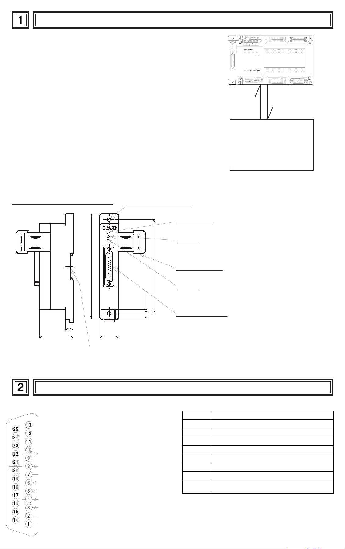
The FX-232ADP type RS232C adapter (hereinafter called 232ADP)
is connected to the FX(V3.07 or later),FX2C series PC to exchange serial
data with a personal computer, barcode reader, printer, and other various
RS232C devices.
●
Only one 232ADP unit can be connected to one base unit to the serial
port provided at the left side.
●
The buffer size and location are specified by an RS instruction in the PC.
●
This product cannot be combined with special adapters such as
FX-8AV,FX2-40AP/AW, or the lide.
LSG24+ RUN
N
POWER RUN BATT¥V
COM COM
PROG
CPU
POWER
RD
SD
RS232C device
E
E
Transmit and/or receive
EXTERNAL DIMENSIONS
POWER
RD
SD
140
(5.51)
(0.39) 10
45
(1.77)
Weight : approx.0.2 kg dimensions : mm (inch)
25 (0.98)
DIN rail width : 35
2-φ5.5 mounting holes
(0.22)
125
(4.92)
12.5
(0.49)
POWER LED
Lit up by the DC 5 V power supplied from the base unit.
RD LED
Lit when receiving data from the RS232C device
connected to the product.
Connection cable
Used for connection with FX or FX2C PC.
SD LED
Lit when transmitting data to the RS232C device
connected to the product.
RS232C connector
Used for connection between the product and RS-232C
device.
TERMINAL LAYOUTS
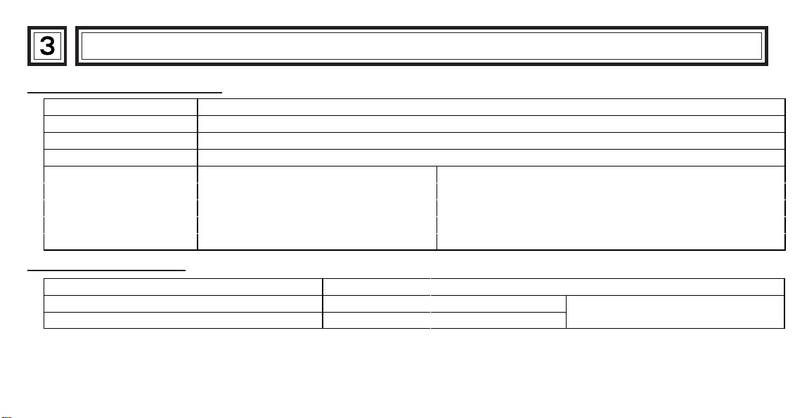
The connector is a 25-pin D-SUB type, and the pin configuration is as shown below.
Pin No. Function
Pins 4, 5 are not used.Short-circuited inside.
ER(DTR)Send request (Data Terminal Ready)
CD(DCD)Carrier Detection
SG(Signal Ground)
DR (DSR) Send enable (Data Set Ready)
CS (CTS) Send enable
RS (RTS) Send request
RD (RXD) Receive data
SD (TXD) Send data
FG Frame ground
1 Frame ground
2 Send data (232ADP to RS232C device)
3 Receive data (RS232 device to 232ADP)
4 • 5 Not used
6 Shows RS232C device is ready to receive
7 Signal ground
8 On when carrier is detected for data reception
20
Signal requesting preparation for data
sending to RS232C device.
Page 3
INSTALLATION NOTES AND USAGE
Performance specification
Transmission standard Conforming to RS232C, 25pin D-SUB, connector used
Isolation method Photo coupler isolation
Transmission distance 15m or less (shielded cable recommended)
Current consumption DC 5V 200mA form base unit
M8121:Send wait flag D8120:Communication format
Related flag
and data registers
General specification
Genelal specifications (excluding following) Same as those for FX or FX2C base unit
Dielectric withstand voltage 500V AC 1min Between 25-pin D-SUB and base
Insulation resistaice 500V DC, 1MΩby Megger
M8122:Send flag D8122:Remainder of send data
M8123:Receive completion D8123:Number of received data
M8124:Carrier detection D8124:Header byte
M8161:8 bits/16 bits changeover D8125:Terminator byte
unit
Page 4

●
For data transmission to be effective it is necessary to match the communication format between the product and the
RS232C device, such as baud rate and parity.
Communication format D8120 (bit mapping)
Bit Description 0 (OFF) 1 (ON)
b 0 Data length 7bit 8bit
b 1
b 2
b 3 Stop 1bit 2bit
b 4
b 5
b 6
b 7
●
The communication format is set by special data register D8120.
Parity
Baud rate
(bps)
(00) : None
(01) : Odd
(11) : Even
(0011) : 300
(0100) : 600
(0101) : 1,200
(0110) : 2,400
(0111) : 4,800
(1000) : 9,600
(1001) : 19,200
Bit Description 0 (OFF) 1 (ON)
b 8 Header None D8124 *1
b 9 Terminator None D8125 *2
b10 Not used - - - - - -
b11
b12 Control line None H/W
b13
b14
b15
Mode
(Control line)
Not used - - - - - -
Ordinary
mode
Single line
mode
*1 The default value is STX (02H: changeable).
*2 The default value is ETX (03H: changeable).
Setting the communication format using D8120 is effective only at the time the RS instruction is driven, and therefore
if changed after driving, it is not actually accepted.
●
An example of setting D8120 is shown below.
M8002
Setting input
[MOV D8120]H138F
H138F= 0001 0011 1000 1111(binary)
The settings for the above program are as right.
●
The control line is set by b12.
b0
Data length 8 bit
Parity Even
Stop 2 bit
Baud rate 9,600
Header Used
Terminator Used
Control line H/W
Mode Ordinary mode
b12=0 :No hardware hand shaking.Send and receive are controlled by software protocol.
b12=1 :Hardware hand shaking.Signal lines ER(DTR)and DR(DSR)are used to control send and receive of data.
b12 1
b11 0
H/W.
Ordinary
mode
When sending
Pin No.
SD(TXD)
ER(DTR)
DR(DSR)
Send
Data
When receiving
Pin No.
RD(RXD)
ER(DTR)
DR(DSR)
Receive
Data
b12 1
b11 1
H/W.
Single line
mode
Pin No.
SD(TXD)
RD(RXD)
ER(DTR)
Send
Data
Receive
Data
Page 5
WIRING
●
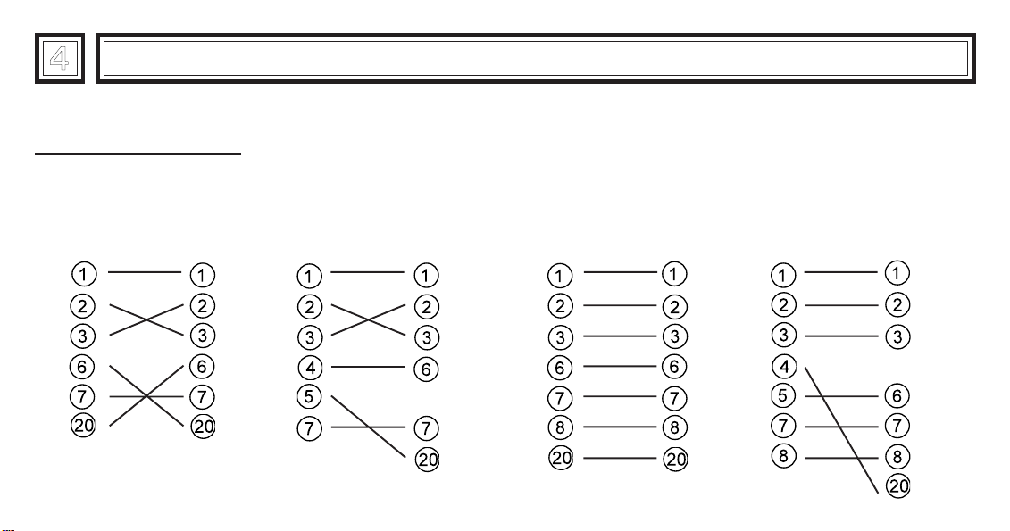
The connections of RS232C devices varies with each device being used.
Check the specification of the device, and connect.
Connection examples
●
Terminal specification device
When RS232C device
uses pins 6,20
RS232C
device
FX-232
ADP
When RS232C device
uses pins 4,5
RS232C
device
FX-232
ADP
●
Modem specification device
When RS232C device
uses pins 6,20
RS232C
device
FX-232
ADP
When RS232C device
uses pins 4,5
RS232C
FX-232
device
ADP
Page 6
PROGRAM EXAMPLES
●
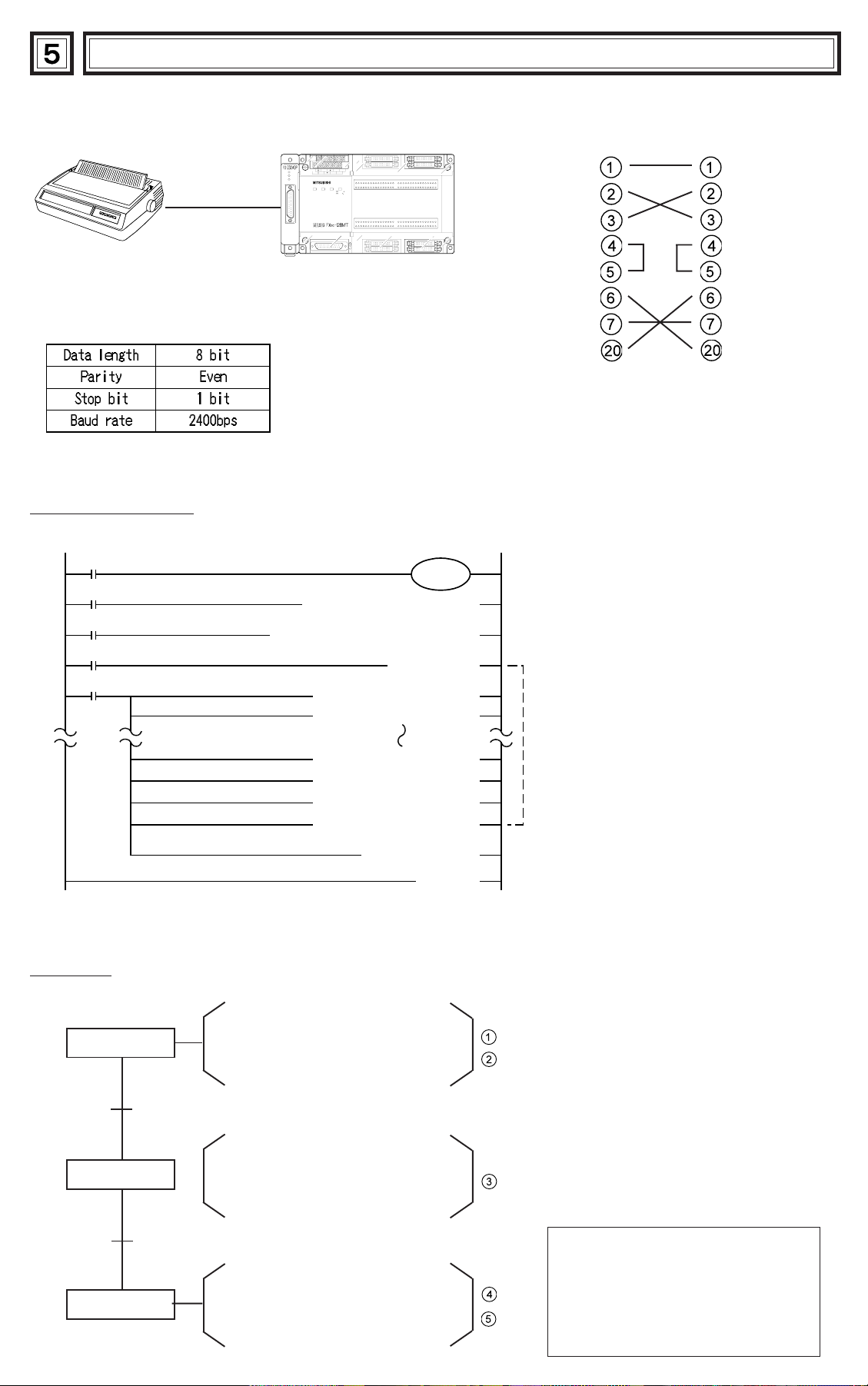
Connecting 232ADP and a printer,and printing out the data sent from the PC.
FX, FX2C series PC
POWER
RD
SD
Send
• Receive data
●
The communication format of the serial printer is as follows.
COM COM
LSG24+ RUN
N
E
PROG
POWER RUN BATT¥V
E
CPU
• Send data
Sequencer program
M8000
0
19
22
80
M8002
3
X000
9
X001
M 0
[ MOV H0067 D8120 ]
[ RS D200 K11 D500 K0 ]
[ PLS M0 ]
[ MOV H0074 D200 ]
[ MOV H0065 D201 ]
[ MOV H006E D207 ]
[ MOV H0065 D208 ]
[ MOV H000D D209 ]
[ MOV H000A D210 ]
[ SET M8122 ]
M8161
[ END ]
Common pin out for printer communication
…
Handled by 8-bit data
…
Setting of communication format
…
RS instruction drive
Writing of send data
①
②
③
④
Herein, "test line" is sent.
…
Send request
⑤
Operation
Power on
X000,ON
RS instruction
drive
X000,ON
Data send
Turn on the power of the PC and
printer, check the printer is on line
and switch the PC to RUN.
Turn on X000, and drive RS
instruction.
Every time X001 is turned on, the
contents of D200 to D210 are
sent to the printer, and
"test line" is printed.
●
In this example, CR (H000D) and LF
(H000A) are written at the end of the
message.The printer moves down
one line for each message.
CR: Carriage Return
LF: Line Feed
Note:It may be necessary to set the
DIP switches of your printer.
Check your printer manual for how to
configure the serial communications.
Page 7
●
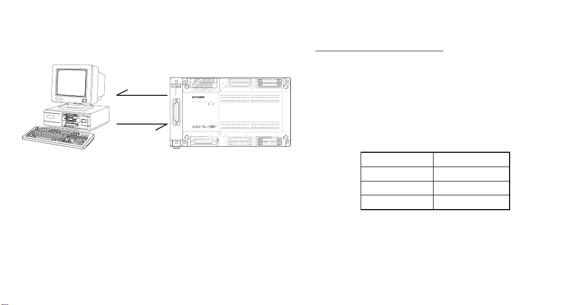
Connect 232ADP and a personal computer,and exchange data with the PC.
Personal computer
FX,FX2C series PC
Send
POWER
RD
SD
LSG24+ RUN
N
POWER RUN BATT¥V
COM COM
PROG
E
E
CPU
Receive
• Receive data
• Send data
●
Use the communication cable suited to the connector pin
• Send data
• Receive data
configuration of the personal computer.
(For representative wiring see section 4.)
Preparation of software
●
Use ordinary communication software (terminal
emulator) or dedicated program in the personal
computer.
The communication format of the PC for this example is
as follows.
Data length 8 bit
Parity Even
Stop bit 1 bit
Baud rate 2400
If the communication format of the software cannot be
adjusted to this setting, adjust the PC and the software
to be the same.
Page 8
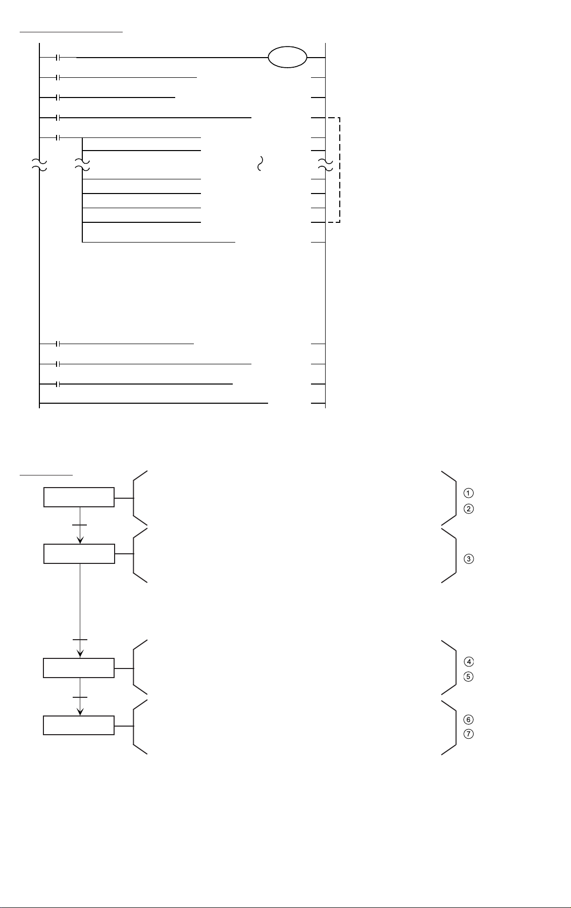
Sequence program
19
22
80
81
89
92
0
3
9
M8000
M8002
X000
X001
M 0
M8123
X002
M 1
M8161
[ MOV H0067 D8120 ]
[ RS D200 K11 D500 K1 ]
[ PLS M0 ]
[ MOV H0074 D200 ]
[ MOV H0065 D201 ]
[ MOV H0074 D207 ]
[ MOV H0061 D208 ]
[ MOV H000D D209 ]
[ MOV H000A D210 ]
[ SET M8122 ]
[ MOV D500 K4Y000 ]
[ PLS M1 ]
[ RST M8123 ]
…
Handled by 8-bit data
…
Setting of communication format
…
RS instruction drive
Writing of send data
①
③
④
Herein, "test line" is sent.
…
Send request
…
Output of receive data
…
Receive completion reset
⑤
⑥
②
⑦
96
Operation
Power on
X000,ON
RS instruction
drive
X001,ON
Data send
Personal
computer
operation
Data send
[ END ]
Turn on the power of the PC and printer, check the printer is on
line and switch the PC to RUN.
Turn on X000, and drive RS instruction.
Every time X001 is turned on, the contents of D200 to D210 are
sent to the personal computer, and "test data" is displayed.
After receiving and storing data from personal computer in D500,
it is output to Y000 to Y017. When input X002 is turned on, the
receive completion flag is reset.
Page 9

DIAGNOSTICS
●
If data transfer does not perform correctly when using
the 232ADP, check the operation using the following
programs.
●
Program when sending
M8002
[ MOV H**** D8120 ]
●
Set the communication format according
M8000
to the external device to be used.
[ RS D0 K20 D100 K0 ]
M8013
[ PLS M0 ]
M0
[ SET M8122 ]
Send request
[ END ]
* Write the data to be sent to D 0 to D 19 before operating.
●
If sending and receiving using these programs is
successful, it is considered that the operation failure
was due to sequence program or communication
protocol error.
●
Program when receiving
M8002
[ MOV H**** D8120 ]
●
Set the communication format according
to the external device to be used.
●
Header and terminator are not attached.
M8000
[ RS D0 K20 D100 K0 ]
M8000
[ RST M8123 ]
Receive completion reset
[ END ]
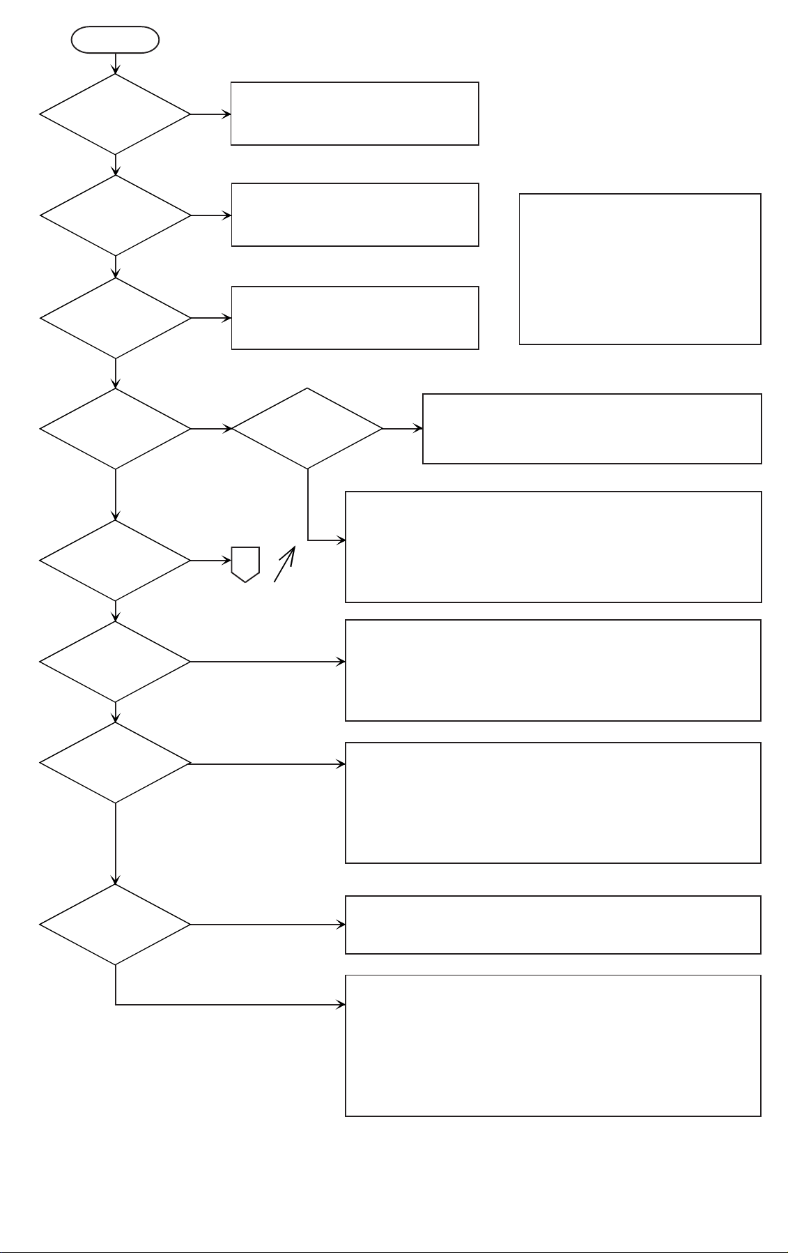
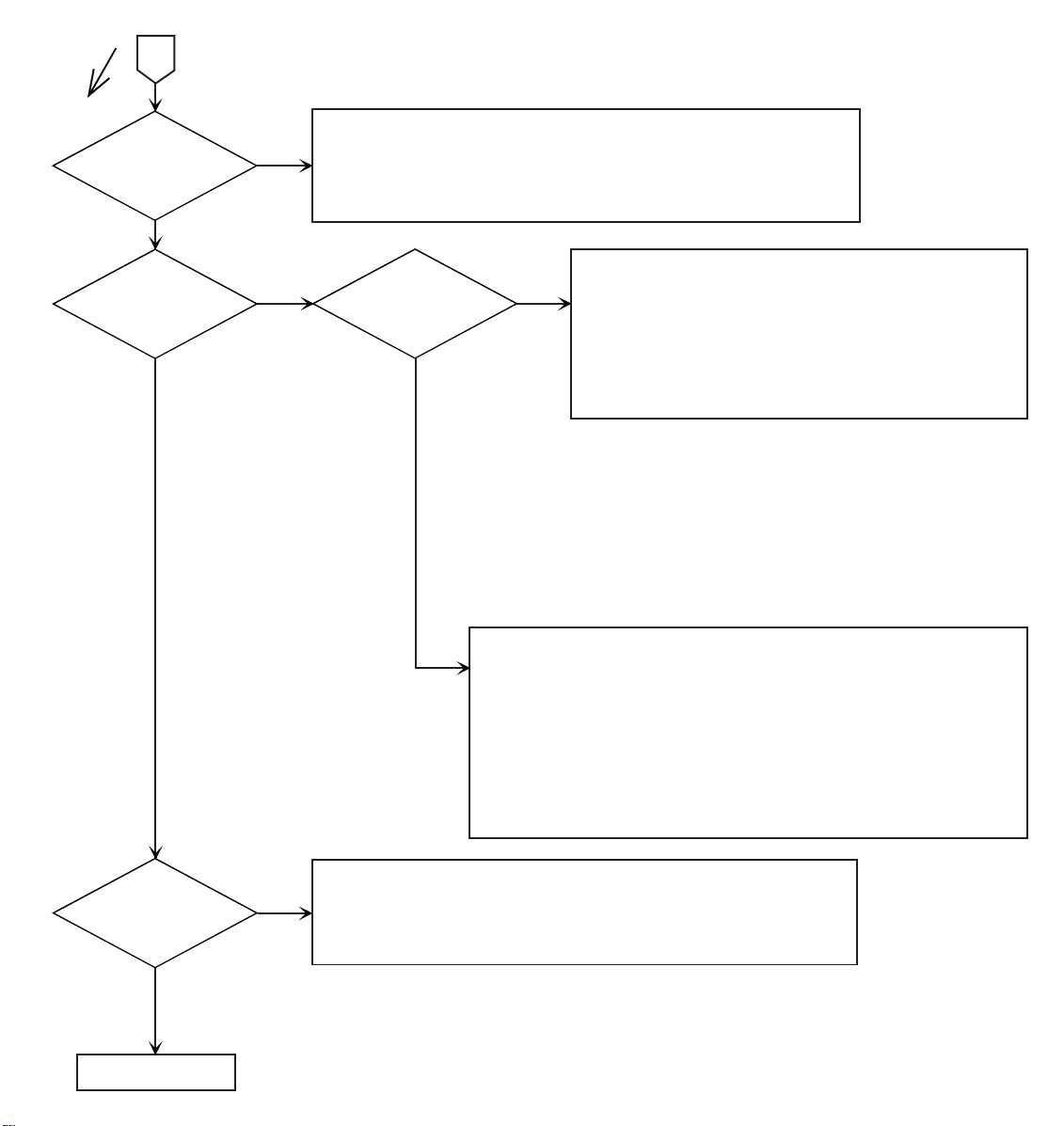
●
If not operating normally when using these programs,
eliminate the cause using the flow diagrams shown
following.
Page 10
Start
Is power
LED lit?
YES
NO
• Check connection with the PC.
• Check power source of PC.
Is VRRD
VRSC
instruction
used?
Are M8070,
M8071
turned on?
Is M8063
turned on?
No send
or receive
error
Only receiving
fails to operate
normally
Is send
wait flag M8121
turned on?
NO
NO
NO
NO
NO
YES
YES
YES
Send,
receive
error
YES
• Eliminate VRRD. VRSC
instruction and reset power source.
• Reset M8070, M8071, and
reset power source.
• Match the communication format.
NO
• Check the wiring of control line.
• Check the start timing of send, receive.
1
The data
transfer
complates
once.
YES
YES
No send or receive error
• There is a possibility of send crosstalk. Check the send and receive
timing with the external RS232C device.
• The receive data length may exceed the receive data area.
Check the receive data length and timing of receive start.
• Check that the program is not set so that M8122 may be always on.
• Check wiring of control line.
• Check timing of send, receive.
• Change RS instruction from OFF to ON.
• Make sure the received data length matches with the receive
data area length.
}
Note: Only one of the following de-
vices can be connected to
the communications port on
the left of the PC:
FX-8AV, FX2-40AW,
FX2-40AP, FX-232ADP.
FX-485ADP
Is SD LED
(send) lit up
momentarily?
YES
Is the send
data remainder
zero?
YES
NO
• Check wiring of RS232C cable.
• Check wiring of control line.
• Make sure the receiving external device is normal.
• Check the voltage level of RS232C signal (±9 V).
• Make sure content of send data and communication format
are established before driving RS instruction.
NO
• Check the timing of control line.
• Check the wiring of RS232C cable.
• Check the wiring of control line.
• Match the communication format.
• Make sure the receiving external device is normal.
(CR, LF may be needed in some printers.)
• Check the data format of sending device.
Page 11
Is RD LED
(receive) lit?
Is M8123
turned on?
Receive
completion
1
YES
YES
• Check wiring of RS232C cable.
NO
• Make sure wiring of control line is suited to the external device.
• Make sure the external sending device is normal.
• Check the voltage level of RS232C signal.
NO
No receive
completion
All data is
received?
(Monitoring D8123)
NO
YES
• Check if receive data length is exceeding the data
area length.
When using terminator
• Make sure the external sending device is sending
the terminator.
• Make sure the terminator value matches.
Are the
contents of
receive data
unintelligible?
NO
Normal
• Match the communication format.
• Check the timing of control line.
• Check if the send data length is not zero when driving RS instruction.
When using header
• Make sure the external sending device is sending the header.
When using terminator
• Check the timing of send, receive.
YES
• Monitor data in hexadecimal notation (HEX).
• Check on/off of M8161.
• Confirm send data format of the sending device.
[ When M8123 is reset, the PC returns to the wait state. ]
Page 12
Guidelines for the safety of the user and protection of the FX-232ADP
• This manual has been written to be used by trained and competent personnel. This is defined by the
European directives for machinery, low voltage and EMC.
• If in doubt at any stage during the installation of the FX-232ADP always consult a professional electrical
engineer who is qualified and trained to the local and national standards.If in doubt about the operation or
use of the FX-232ADP please consult the nearest Mitsubishi Electric distributor.
• Under no circumstances will Mitsubishi Electric be liable or responsible for any consequential damage that
may arise as a result of the installation or use of this equipment.
• All example and diagrams shown in this manual are intended only as an aid to understanding the text, not
to guarantee operation. Mitsubishi Electric will accept no responsibility for actual use of the product based
on these illustrative examples.
• Owing to the very great variety in possible application of this equipment, you must satisfy yourself as to its
suitability for to your specific application.
JY992D48801B
Manual number : JY992D48801
Manual revision : B
Date : JUNE 1996
HEAD OFFICE:MITSUBISHI DENKI BLDG MARUNOUCHI TOKYO 100 TELEX:J24532 CABLE MELCO TOKYO
HIMEJI WORKS:840, CHIYODA CHO, HIMEJI, JAPAN
Effective JUN.1996
Specifications are subject
to change without notice.
 Loading...