

Page 1

Page 2

Page 3

Windows® is either registered trademark or trademark of Microsoft Corporation in the United States and/or other
countries.
MELDAS is a registered trademark of Mitsubishi Electric Corporation.
Other company and product names that appear in this manual are trademarks or registered trademarks of their
respective companies.
Page 4

Page 5
Introduction
This is an instruction manual for NC Monitor, which is software compatible with MITSUBISHI CNC M700V,
M70V, M700 and M70 Series.
This manual describes how to operate NC Monitor, so read this thoroughly before using. Also understand the
contents of "Precautions for Safety" on the next page for safely using MITSUBISHI CNC M700V, M70V, M700
and M70 Series.
Details described in this manual:
CAUTION
If the descriptions relating to the "restrictions" and "allowable conditions" conflict between this manual
and the machine tool builder’s instruction manual, the latter has priority over the former.
The operations to which no reference is made in this manual should be considered "impossible".
This manual is written on the assumption that your machine is provided with all optional functions.
Refer to the specifications issued by machine tool builder to confirm the functions available for your NC
before proceeding to operation.
In some NC system versions, there may be cases that different pictures appear on the screen, the
machine operates in a different way or some function is not activated.
Page 6

Page 7
Precautions for safety
Make sure to read this manual, related manuals and auxiliary documents carefully before starting installation,
operation, programming, maintenance or inspection to ensure correct usage. Thoroughly understand the device,
safety information and precautions of this control system before starting operation.
This manual ranks the safety precautions into "DANGER", "WARNING" and "CAUTION".
DANGER
WARNING
CAUTION
Note that some items ranked as "
In any case, important information that must always be observed is described.
When the user may be subject to imminent fatalities or major injuries if handling is mistaken.
When the user may be subject to fatalities or major injuries if handling is mistaken.
When the user may be subject to injuries or when physical damage may occur if handling is
mistaken.
CAUTION" may lead to major results depending on the situation.
DANGER
Not applicable in this manual.
WARNING
Not applicable in this manual.
1. Items related to product and manual
CAUTION
If the descriptions relating to the "restrictions" and "allowable conditions" conflict between this manual
and the machine tool builder's instruction manual. the latter has priority over the former.
The operations to which no reference is made in this manual should be considered "impossible".
This manual is written on the assumption that your machine is provided with all optional functions.
Refer to the specifications issued by machine tool builder to confirm the functions available for your
machine before proceeding to operation.
In some NC system versions, there may be cases where different pictures appear on the screen, the
machine operates in a different way or some function is not activated.
Page 8

Page 9

CONTENTS
1. OVERVIEW ............................................................................................... 1
1.1 Outline of NC Monitor ................................................................................. 1
1.2 Specifications of NC Monitor ........................................................................... 2
1.2.1 Operating environment of NC Monitor.............................................................2
1.3 Screen Configuration of NC Monitor..................................................................... 3
1.3.1 Menu bar ..................................................................................... 4
1.3.2 Tool bar....................................................................................... 5
1.3.3 Connected NC data ............................................................................ 5
1.3.4 NC list area ................................................................................... 6
1.3.5 Screen display window.......................................................................... 8
2. INSTALLATION AND SETUP ................................................................................ 9
2.1 How to Install onto Your Computer for the First Time ......................................................9
2.2 How to Install to Upgrade the Software ................................................................. 13
2.3 How to Uninstall ..................................................................................... 14
2.3.1 Use Control Panels to uninstall ................................................................. 14
2.3.2 Use NCMonitor.exe to uninstall ................................................................. 15
3. HOW TO USE NC MONITOR...............................................................................17
3.1 Start and Terminate NC Monitor .......................................................................17
3.1.1 Start NC Monitor ..............................................................................17
3.1.2 Terminate NC Monitor .........................................................................17
3.2 Connect and Disconnect ............................................................................. 18
3.2.1 Display the connected NC's screen (Connect) .................................................... 18
3.2.2 Close the connected NC's screen (Disconnect) ................................................... 18
3.2.3 Change NC name ............................................................................. 19
3.2.4 Add connected NC ............................................................................ 20
3.2.5 Delete connected NC .......................................................................... 21
3.2.6 Update connected NC .........................................................................21
3.2.7 Switch languages .............................................................................21
3.2.8 Arrange windows.............................................................................. 21
3.2.9 Version information............................................................................21
3.3 Display/Setting Limitations of Connected NC ............................................................22
3.4 Points to Note.......................................................................................23
APPENDIX ................................................................................................. 24
Appendix 1. Messages .................................................................................. 24
Appendix 2. Shortcut Key List ............................................................................ 25
Appendix 3. Restrictions ................................................................................. 26
Appendix 3.1 Common Restriction.................................................................... 26
Appendix 3.2 Restriction on Devices .................................................................. 26
Appendix 3.3 Restriction on System Setup Screen...................................................... 27
Appendix 3.4 Restriction on Guidance ................................................................27
Page 10

Page 11
1. OVER VIEW
1. OVERVIEW
This chapter explains the outline of NC Monitor.
1.1 Outline of NC Monitor
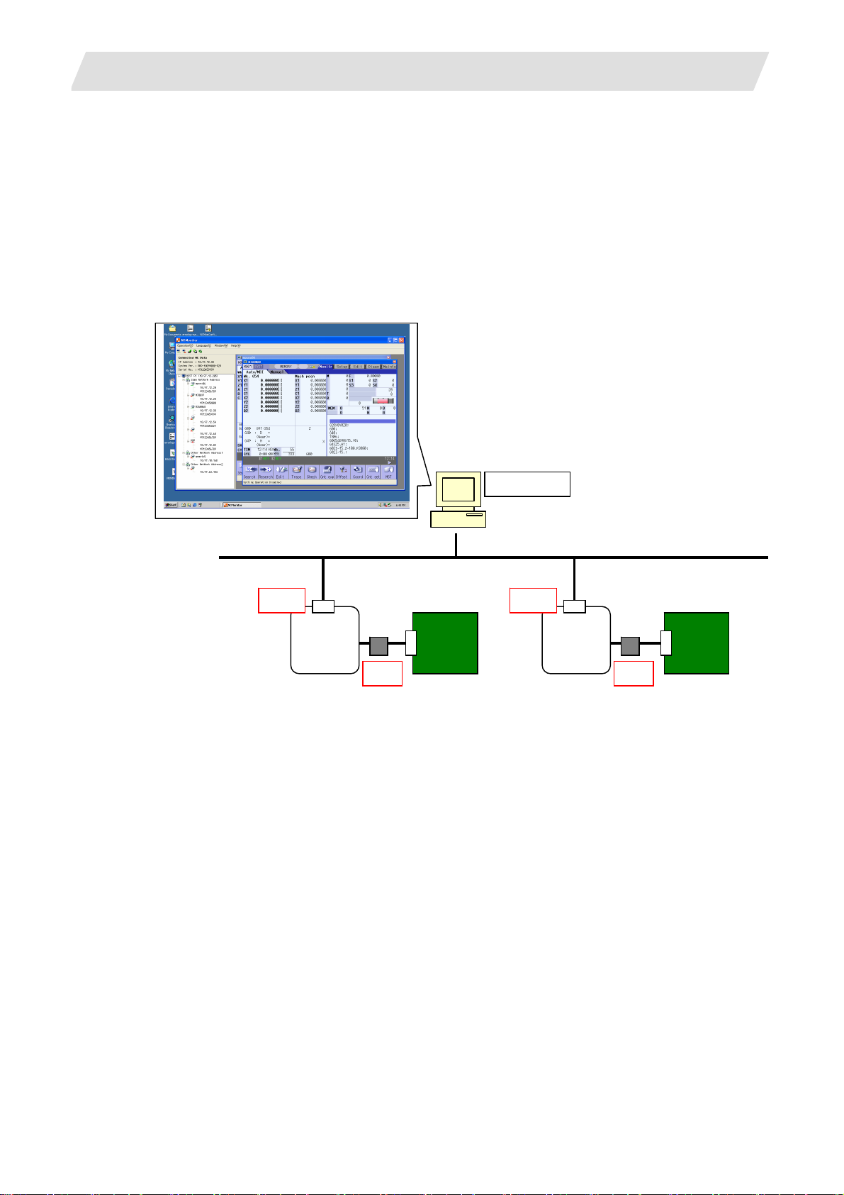
NC Monitor is software which enables monitoring of remote numerical controllers (referred to as NCs) by use
of the intranet on production site.
NC Monitor is possible to connect to more than one NC, thus it can monitor multiple NCs at a time.
1.1 O utline of NC Monit o r
Host PC
LAN1 LAN1
NC
(the 1st)
OP1 OP1
Display Display
NC
(the 2nd)
Figure1-1 General schematic diagram
1
Page 12
1. OVER VIEW
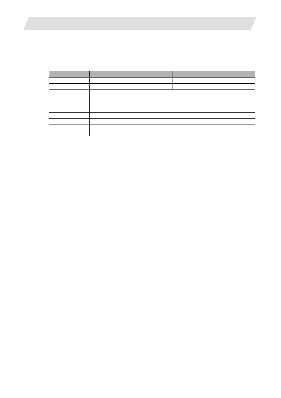
1.2 Specifications of NC Monitor
1.2.1 Operating environment of NC Monitor
NC Monitor works under the following environment.
Item Windows 2000/XP Windows Vista
Computer A PC with 300MHz or faster CPU A PC with 800MHz or faster CPU
Memory 128MB or more 512MB or more
Available hard
disk space
OS Windows 2000 SP3 or later / Windows XP SP2 or later / Windows Vista SP1
Interface 10/100M Ethernet
Display Video adapter (SVGA) with a resolution of 800x600 and a monitor
NCs to connect Version F0 (F2 for M700VW Series or G0 for M70V Series) or later of the
100MB or more (excluding the free space necessary for running the OS)
or later
M700, M70, M700VS, M700VW and M70V Series NCs
1.2 Specificatio ns of NC Monitor
2
Page 13
1. OVER VIEW
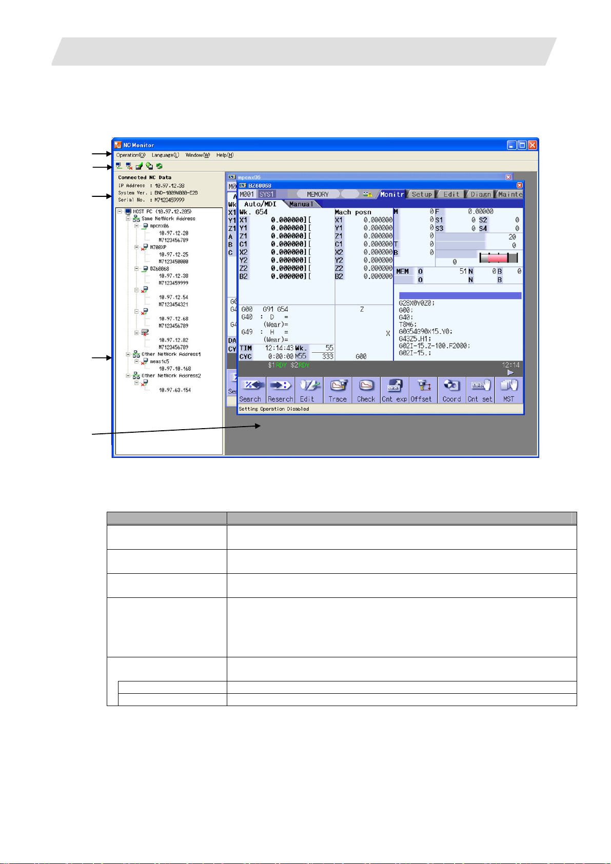
1.3 Screen Configuration of NC Monitor
The NC Monitor screen is as shown in Figure 1-2.
(1)
(2)
(3)
1.3 Sc re e n Con f iguration of NC Monitor
(4)
(5)
Figure 1-2 NC Monitor screen configuration
Table 1-1 List of items displayed
Item Description
(1) Menu bar Possible to select functions such as connection (to display the screen) and
addition of NC.
(2) Tool bar Possible to use frequently used functions without selecting from the menu
bar.
(3) Connected NC data Detailed information (such as IP address, system version and serial No.) of
the connected NC, which is displayed in the foreground, appears.
(4) NC list area A list of NCs is displayed.
In this list, connectable NCs and the NCs added by a user using "Add
connected NC" function are listed.
When an item is selected from the list and right-clicked, a popup menu
appears, from which various functions can be selected.
(5) Screen display
Screens of the connected NCs are displayed.
window
Title bar The connected NC's name and the close button are displayed.
Status bar Tool's status, such as communication state, is displayed.
3
Page 14

1. OVER VIEW
1.3.1 Menu bar
Menu bar contains various functions to select, such as connection/disconnection with NC and addition of
connected NC.
(2) [Language] menu
(3) [Window] menu
(4) [Help] menu
1.3 Sc re e n Con f iguration of NC Monitor
(1) [Operation] menu
Using this menu, you can perform operations such as connection with NC.
Table 1-2 Items in Operation menu
Item Description
Connect (O) Connects to an NC to display the NC's screen.
If the NC you've selected from the NC list is already connected (its
screen is being displayed), this NC's screen is displayed in the
foreground.
If a cursor is not over NC in the list area, selecting this item is not
possible.
Disconnect (C) Cuts off the connection to the NC and closes the NC's screen.
When this tool is not connected to the NC, which you've selected
from NC list (when this tool is not displaying the selected NC's
screen), or when a cursor is not over an NC in the list area,
selecting this item is not possible.
Change NC Name
)
(R
Opens the [Change NC Name] dialog box, where you can change
the name of NC that is pointed by a cursor in the NC list area.
If a cursor is not over an NC in list area, selecting this item is not
possible.
Add connected NC
)
(A
Opens the [Add connected NC] dialog box, where you can add an
NC that belongs to the other network group (a group different from
the host PC's IP address) to the NC list.
Delete connected
)
NC (D
Deletes an NC, which you've added by "Add connected NC"
function, from the NC list.
When the NC you've selected from the list is already connected
(its screen is being displayed) or when a cursor is not pointing at
an NC which belongs to the other network group (a group different
from the host PC's IP address) in the list area, selecting this item is
not possible.
Update (U) Refreshes the list of the connectable NCs (NCs belonging to the
same network group as the host PC's IP address).
End (X) Terminates the tool.
Using this menu, you can switch the displayed languages of this tool. The default language is
the one selected at the time of installation.
Language switching is enabled after restarting this tool.
Using this menu, you can arrange the screen.
Using this menu, you can see this tool's version information.
4
Page 15

1. OVER VIEW
1.3.2 Tool bar
You
can use the functions such as connect/disconnect without selecting from the menu. When you
move a cursor over the tool bar, a note explaining the function's outline appears.
Item Icon Description
Connect
Disconnect
Change NC
Name
Add
connected
NC
Update
1.3.3 Connected NC data
1.3 Sc re e n Con f iguration of NC Monitor
Table 1-3 Items on Tool bar
Connects to an NC to display the NC's screen.
If the NC you've selected from the NC list is already connected (its
screen is being displayed), this NC's screen is displayed in the
foreground.
Clicking on this button is not possible, if a cursor is not over an NC
in NC list area.
Cuts off the connection to the NC and closes the NC's screen.
If this tool is not connected to the NC, which you've selected from
the NC list (If this tool is not displaying the selected NC's screen),
or if a cursor is not over an NC in NC list area, clicking on this
button is not possible.
Opens [Change NC Name] dialog box, where you can change the
name of NC that is pointed by a cursor in NC list area.
If a cursor is not over an NC in NC list area, clicking on this button
is not possible.
Opens [Add connected NC] dialog box, where you can add an NC
that belongs to the other network group (different from the host
PC's IP address) to the NC list.
Refreshes the list of the connectable NCs (NCs belonging to the
same network group as the host PC's IP address).
This area shows the detailed information of the connected NC whose screen is displayed in the foreground.
When not connected to any NC, only the item name "Connected NC Data" is displayed.
Table1-4 Items in Connected NC Data
Item Description
IP Address Displays the connected NC's IP address (set in the base common
parameter "#1926 Global IP address", which is referred to as NCIP
address).
System Ver. Displays the connected NC's system version.
Serial No. Displays the connected NC's serial number. If the serial number is
not set, it is left blank (only the item name is shown).
5
Page 16

1. OVER VIEW
1.3.4 NC list area
1.3 Sc re e n Con f iguration of NC Monitor
In NC list area, conne
ctable NCs and NCs added by "Add connected NC" function are displayed in
a tree structure.
When you select an item from the list and right click on it, a pop-up menu appears.
(1)
(2)
(3)
(4)
6
Page 17

1. OVER VIEW
1.3 Sc re e n Con f iguration of NC Monitor
Table 1-5 Items in NC list area
Item Description
(1) Icon There are four types of icons:
: means that it is Host PC.
: means that they belongs to the same network group.
: means that it is being connected (its screen is displayed).
: means that it is not being connected (its screen is not
displayed).
(2) HOST PC
(Host PC's IP address)
The host PC's IP address is shown inside the brackets next to
the item name, "HOST PC".
(3) List of connectable NCs This shows a list of connectable NCs, which are displayed in
the following configuration.
├ NC name
├ NCIP address
└ Serial No.
"Connectable NC" means that the NC belongs to the same
network group as the host PC's IP address.
(E.g.)
Host PC's IP address: 10.97.12.205
Host PC's subnet mask: 255.255.255.0
1) NCIP address: 10.97.12.20
→ This NC belongs to the same network address,
10.97.12.0
. So this NC is included in the list.
2) NCIP address: 10.97.10.20
→ The network addresses are different as 10.97.12.0
and 10.97.10.0
, thus this NC is not included in the
list.
(Note 1) Right after the installation of this tool, only
connectable NCs are shown in the list.
(Note 2) When connection to the NC is impossible for a
reason such as the power is OFF, this NC is not
shown in the list.
(Note 3) If the NC name is not set, the NC name is left blank.
It is possible to move a cursor over the blank area.
(4) List of NCs added by the
"Add connected NC"
function
This shows a list of NCs belonging to the other network group
(a group different from the host PC's IP address), which have
been added by the "Add connected NC" function.
These NCs are displayed in the following configuration.
├ NC name
└ NCIP address
(Note 1) See "3.2.4 Add connected NC" for how to add NCs.
(Note 2) All of the added NCs are listed, regardless of
whether the NC is connectable or not.
(Note 3) The added NCs are still displayed in the list, even
after closing and then restarting this tool.
7
Page 18

1. OVER VIEW
1.3.5 Screen display window
1.3 Sc re e n Con f iguration of NC Monitor
This windo
w shows the connected NC's screen.
If there is more than one connectable NC, screens of up to 10 NCs can be displayed.
But, it's not possible to open multiple screens for one NC.
(1)
(2)
(3)
Table 1-1 List of screen elements
Item Description
(1) Title bar Displays the NC name and the close button.
NC name
Displays the connected NC's name.
The name designated by "Add connected NC" or "Change NC Name" is
displayed. When NC name is not set, this is left blank.
Disconnect
Cuts off the connection to an NC to close the NC's screen.
(Close the connected
NC's screen)
(2) Connected NC's
screen
Displays the connected NC's screen.
When the operation parameter "#8931 Display/Set limit" is set to "0" or
"1" and when other host PC or display is being connected (this state is
hereinafter called "host connection state"), the icon
appears.
(Note 1) The NC screen shown by NC Monitor has no [SOFT KEY]
button.
(Note 2) When Anshin (MTB) net communication is active in host
connection state, the icon
is indicated with higher
priority.
(3) Status bar Displays various conditions, such as communication status.
Setting Operation
Disabled
The connected NC's operation parameter "#8931 Display/Set limit" is
set to "1" or "2", thus setting of parameters etc. is impossible via this
tool.
Communication
Abnormalities
While connected NC's screen is being displayed, a communication
failure such as the NC's power OFF has happened.
8
Page 19

2. INST ALLATION AND SETU P
2.1 How to Install onto Your Computer for the First Time
2. INSTALLATION AND SETUP
2.1 How to Install onto Your Computer for the First Time
(1) Double click on NC Monitor.exe.
Select the language to use for installation, and press [Next].
(Note) The installation of NC Monitor has to be carried out by the authority of the administrator.
If User Account Control in Windows Vista is enabled, the confirmation dialog box as below pops up.
Then, allow the execution of NCMonitor.exe to start the installation.
(2) The setup screen appears.
Press [Next].
9
Page 20

2. INST ALLATION AND SETU P
(3) The software license agreement dialog box appears.
Read it through and press [Yes].
Select [No] (if you don't agree to this) to cancel the installation of NC Monitor.
2.1 How to Install onto Your Computer for the First Time
(4) The user information dialog box appears.
Input your user name and company name, and then press [Next].
(5) Input the product ID and press [Next].
10
Page 21

2. INST ALLATION AND SETU P
(6) The installation location selection screen appears.
If you wish to change where to install, press [Browse] and select the location.
After setting, press [Next].
(7) The setup type information appears. After selecting the setup type, press [Next].
2.1 How to Install onto Your Computer for the First Time
(8) The information on the installation location appears. Check the location setting and then press
[Next] (or [Back] to change the setting).
Then the setup starts.
11
Page 22

2. INST ALLATION AND SETU P
(9) Only when the configuration file for Mitsubishi CNC already exists, a dialog box appears asking whether to
change the setting to that for NC Monitor.
If you wish to change it to that for NC Monitor, press [Yes]. If you wish to use the conventional setting,
press [No]. Normally select [Yes].
(10) When the installation has finished normally, the completion dialog box appears.
Press [Finish] to end the procedure.
2.1 How to Install onto Your Computer for the First Time
12
Page 23

2. INST ALLATION AND SETU P
2.2 How to Install to Upgrade the Software
(1) Double click on the new version of NCMonitor.exe.
Select [Repair] and press [Next].
(2) A confirmation dialog pops up asking whether to change the setting of the configuration file for Mitsubishi
CNC to the setting for NC Monitor.
If you wish to change to NC Monitor's setting, press [Yes], or if you wish to maintain the conventional
setting, press [No].
Normally select [Yes].
2.2 How to Install to Upgrade the Software
(3) When the installation has finished normally, the completion dialog box appears.
Press [Finish] to end the procedure.
13
Page 24

2. INST ALLATION AND SETU P
2.3 How to Uninstall
There are two kinds of ways to uninstall NC Monitor; one is by using Control Panels and the other is by double
clicking NC Monitor.exe.
2.3.1 Use Control Panels to uninstall
(1) Select [Start] - [Control Panels] - [Add/Remove Programs].
The [Add/Remove Programs] screen appears.
Choose NC Monitor from the list and press the [Change/Remove] button.
2.3 How to Uninstall
(2) The [InstallShield Wizard] screen appears.
Select [Remove] and press [Next].
14
Page 25

2. INST ALLATION AND SETU P
(3) The [Confirm Uninstall] dialog box appears.
Press [OK] to start the uninstallation (or [Cancel] to go back to the [InstallShield Wizard] screen).
(4) When the uninstallation has finished, the completion dialog box appears.
Press [Finish] to end the procedure.
2.3 How to Uninstall
2.3.2 Use NCMonitor.exe to uninstall
(1) Double click on NC Monitor.exe.
The [InstallShield Wizard] dialog box appears.
Select [Remove] and press [Next].
15
Page 26

2. INST ALLATION AND SETU P
(2) The [Confirm Uninstall] dialog box appears.
Press [OK] to start uninstallation (or [Cancel] to go back to [InstallShield Wizard] screen).
(3) When the uninstallation has finished, the completion dialog box appears.
Press [Finish] to end the procedure.
2.3 How to Uninstall
16
Page 27

3. HOW TO USE NC MONI TOR
3. HOW TO USE NC MONITOR
This chapter explains how to operate NC Monitor.
3.1 Start and Terminate NC Monitor
3.1.1 Start NC Monitor
Select [NC Monitor] from the [Start] menu to activate this tool.
More than one NC Monitor can't be activated at a time.
When there is more than one network card (such as both wired LAN and wireless LAN), NC monitor
(Note)
uses the IP address of the first found network card as the host PC's IP address.
This host PC's IP address is used for searching for connectable NCs, determining network group, and
so on.
To specify an arbitrary fixed IP address, designate the IP address to the start argument, as “/NIC
xxx.xxx.xxx.xxx”.
If the IP address specified for the network card does not exist, an error message appears.
After the error message is closed, NC Monitor will start in the same state as when there is no
argument specification.
(E.g.) When the host PC's IP address is 192.168.1.1
3.1 Start and Terminate NC Monitor
3.1.2 Terminate NC Monitor
Perform either one of the followings to terminate this tool;
(a) Select [Operation (O)] and [End (X)] from the menu bar.
(b) Click on × button on the tool's title bar.
If this tool is in connection state (displaying NC's screen), connection with NC is cut off and the NC's screen is
closed.
Add the argument to the link.
17
Page 28

3. HOW TO USE NC MONI TOR
3.2 Connect and Disconnect
3.2.1 Display the connected NC's screen (Connect)
To connect this tool with an NC to display the NC's screen, select the NC to connect from the NC list and
perform one of the followings.
(a) Select [Operation (O)] and [Connect (O)] from the menu bar.
(b) Click on
(c) Right click to open its pop-up menu and select [Connect (O)].
(d) Double click.
(e) Press the [Enter] key.
After NC connection is completed, the NC's icon in the NC list area is changed from
If the NC you've selected is already in connection state (its screen is being displayed), the connected NC's
screen is displayed in the foreground.
If connection fails due to problems such as the selected NC's power is OFF or communication trouble, the
[Connection Error] message box pops up.
Similarly, when the selected NC's parameter "#8931 Display/Set limit" is set to "2" (Restrict display on NC
Monitor), the connection error dialog box pops up.
3.2.2 Close the connected NC's screen (Disconnect)
on the tool bar.
3.2 Connect and Disc on nect
to .
Perform one of the followings to cut off the connection with NC and close the NC's screen.
(a) Select an NC to cut off from NC list and select [Operation (O)] - [Disconnect (C)] from the menu bar.
(b) Select an NC to cut off from NC list and click on
(c) Right click to open the pop-up menu and select [Disconnect (C)].
(d) Click on × button on the screen display window's title bar.
After the cutoff, the NC's icon in the NC list area changes from
button on the tool bar.
to .
18
Page 29

3. HOW TO USE NC MONI TOR
3.2.3 Change NC name
If you wish to change the NC name, select the NC from the NC list and perform one of the followings to open
the [Change NC Name] dialog box.
(a) Select [Operation (O)] and [Change NC Name (R)] from the menu bar.
(b) Click on
(c) Right click to open the pop-up menu and select [Change NC Name (R)].
The connected network address is shown in IP Address, Subnet Mask and Default Gateway boxes.
Input an arbitrary NC name and click on OK button.
Then, the [Change NC Name] dialog box closes and the screen is switched back to the NC Monitor operation
screen.
The new NC name is shown in the NC list.
If you've changed the NC name, which is already in connection state (its screen is being displayed), the new
name is also shown on Screen display window's title bar.
To cancel this operation, click on × or CANCEL button.
The NC name can be up to 32 one-byte characters in length.
button on the tool bar.
3.2 Connect and Disc on nect
19
Page 30

3. HOW TO USE NC MONI TOR
3.2.4 Add connected NC
If you wish to add an NC that belongs to the other network group (a group different from the host PC's IP
address), perform one of the followings to open the [Add connected NC] dialog box.
(a) Select [Operation (O)] and [Add Connected NC (A)] from the menu bar.
(b) Click on
(c) Right click on the NC list area to open the pop-up menu and select [Add connected NC (A)].
Input the NC name and network address (IP address, subnet mask and default gateway) and click on OK.
Then, the [Add connected NC] dialog box closes and the screen is switched back to NC Monitor.
Added NCs, both connectable and non-connectable, are all included in the NC list area.
(Even if you designate an NC whose power is OFF, for example, the NC is also added to the list.)
If you attempt to add a network address which is already registered (displayed in the NC list area), the
[Duplication Error] message box pops up.
If the network address includes a value outside the setting range (between 0 and 255), the [Setting Error]
message box pops up.
If you wish to cancel the operation, click on × or CANCEL button.
The NC name can be up to 32 one-byte characters in length.
on the tool bar.
3.2 Connect and Disc on nect
20
Page 31

3. HOW TO USE NC MONI TOR
3.2.5 Delete connected NC
If you wish to delete an NC that belongs to a network group different from the host PC's IP address, which
you've added by "Add connected NC" function (See "3.2.4 Add connected NC"), perform either one of the
followings.
(a) Select an NC to delete from the NC list and select [Operation (O)] and [Delete connected NC (D)] from the
menu bar.
(b) Select an NC to delete from the NC list and right click on it to open the pop-up menu. Then select [Delete
connected NC (D)].
Then, the [Confirmation of Connected NC Deletion] message box pops up.
Click on the [Yes] button to delete the NC.
Click on the [No] button to cancel the deletion.
You cannot delete an NC which belongs to the same network group as the host PC's IP address.
3.2 Connect and Disc on nect
3.2.6 Update connected NC
If you wish to refresh the list of NCs that belong to the same network group as the host PC's IP address,
perform either one of the followings.
(a) Select [Operation (O)] and [Update (U)] from the menu bar.
(b) Click on
3.2.7 Switch languages
If you wish to change the language displayed on NC Monitor, select [Language (L)] and [English (E)] or
[Language (L)] and [Japanese (J)] from the menu bar.
After the language switching, a message box requesting you to restart the tool pops up.
After restarting the tool, selected language display is enabled.
This tool will not be restarted automatically just by pressing the OK button.
(Note)
3.2.8 Arrange windows
on the tool bar.
If you wish to display multiple NCs' screens in an aligned (overlapped) manner, select [Window (W)] and
[Overlap Display (C)] from the menu bar.
3.2.9 Version information
If you wish to check NC Monitor's version, select [Help (H)] and [Version Information (A)] from the menu bar to
open the [Version Information] dialog box.
21
Page 32

3. HOW TO USE NC MONI TOR
3.3 Display/Setting Limitations of Connected NC
By setting the NC's operation parameter "#8931 Display/Set limit", you can restrict the NC's display or setting
on or from NC Monitor.
The initial setting value is "0", so there are no limitations in displaying the connected NC on NC Monitor and in
setting operation from NC Monitor.
Parameter "#8931" value Display/Setting operation
0 NC Monitor can display the connected NC's screen. Setting of this
NC is possible from this tool.
1 NC Monitor can just display the connected NC's screen.
2 NC Monitor is unable to connect to the NC.
3. 3 Displa y/S e tti ng Li m i t ati ons of Connec t e d NC
Host PC
・1st NC - - Display/Setting operations enabled.
・2nd NC - - Display enabled. Setting disabled.
・3rd NC - - Display/Setting operations disabled.
LAN1 LAN1
NC
(the 1st)
OP1 OP1
"#8931 Display/Set limit" is "0"
Display Display
LAN1
NC
(the 2nd)
OP1
"#8931 Display/Set limit" is ”1” "#8931 Display/Set limit" is ”2”
Display
Figure 3-14
NC
(the 3rd)
22
Page 33

3. HOW TO USE NC MONI TOR
3.4 Points to Note
There are some points to note when using this tool.
(1) When connected NC's parameter "#8931 Display/Set limit" is set to "0", another host PC or display may be
operating this NC. Thus be careful if you perform setting for this NC.
(2) When the connected NC is M70, M70V or M700VS and you wish to carry out operations (such as search,
edit and input/output) to the memory card, select the [DS] menu. To format the memory card, select [DS
format].
(3) When the screen display window of the connected NC appears, Caps Lock turns ON. Thus please be
careful during setting operation.
3.4 Points to Note
23
Page 34

APPENDIX
APPENDIX
This chapter explains the information which you can refer to in using NC Monitor. Reference this information
when necessary.
Appendix 1. Messages
The messages (message boxes) listed below are shown during each operation of NC Monitor.
Message Meaning Action
Setting
Operation
Invalidity
Communication
Abnormalities
Duplication Error The network address you attempted to
Setting Error The network address you attempted to
Connection Error
The messages listed below are shown on the screen display window only during NC Monitor operation.
Message Meaning Action
Setting operation
is restricted.
Because the connected NC's operation
parameter "#8931 Display/Set limit" is
set to ”1” or ”2”, this tool is unable to do
parameter setting, etc.
Communication failure has occurred
because, for example, the connected
NC's power turned OFF while its
screen was being displayed.
add has been already registered.
add includes a value outside the range
(between 0 and 255), thus failed to add
the address.
・The connected NC doesn't exist.
・The connected NC power is not ON.
・Communication failure
・ The number of connected NCs
reached the maximum.
・Displaying on NC Monitor is restricted.
Connection failed due to one of these
reasons.
Because the connected NC's operation
parameter "#8931 Display/Set limit" is
set to ”1” or ”2”, this tool is unable to do
parameter setting, etc.
Appendix 1. Messages
Change the setting of the connected
NC's operation parameter "#8931
Display/Set limit".
・Check if the connected NC's power
is ON.
・Check if the connected NC has a
proper network connection.
Cancel the operation or set another
network address.
Make sure that the network address
is within the setting range (between
0 and 255).
・Check if the connected NC exists.
・ Turn ON the connected NC's
power.
・Check if the connected NC has a
proper network connection.
・Reduce the number of connected
NCs.
・ Check the setting value of the
connected NC's operation
parameter "#8931 Display/Set
limit".
Change the setting of the connected
NC's operation parameter "#8931
Display/Set limit".
24
Page 35

APPENDIX
Appendix 2. Shortcut Key L ist
Appendix 2. Shortcut Key List
On the connected NC's screen, the following shortcut keys are available.
Keys on NC
keyboard
FUNC
MONITOR Monitor screen SHIFT+F1
SET_UP Setup screen SHIFT+F2
EDIT Edit screen SHIFT+F3
DIAGN Diagnosis screen SHIFT+F4
MAINTE Maintenance screen SHIFT+F5
Part system ($$) Switch $$ CTRL+F1
Help ? Display/Hide the operation/parameter/alarm
Previous
(Back) Select the previous screen CTRL+F6
screen
Menu list MENU LIST Display/Hide the menu list CTRL+F8
Tab
Page
MENU
MENU1 F1
MENU2 F2
MENU3 F3
MENU4 F4
MENU5 F5
MENU6 F6
MENU7 F7
MENU8 F8
MENU9 F9
MENU10 F10
Left <
right >
Delete DELETE DELETE
Insert INSERT INSERT
C.B. Clear the input area SHIFT+Home Cancel
CAN ESC
Input ENTER ENTER
Cursor
↑ ↑
↓ ↓
← ←
→
Left tab (|←) Move the input target cursor SHIFT+TAB Tab
Right tab (→|) Move the input target cursor TAB
Special ABC/abc… Caps Lock
Supplements Keys on PC
keyboard
CTRL+F2
guidance
Backward tab CTRL+F9
Forward tab CTRL+F10
Previous page PageUp
Next page PageDown
Return (Menu) F11
Next menu F12
25
Page 36

APPENDIX
Appendix 3. Restrictions
This tool has the following restrictions.
Appendix 3.1 Common Restriction
(1) More than one NC Monitor cannot start at a time.
(2) Screens of up to 10 connected NCs can be displayed on NC Monitor.
(3) More than one screen cannot be activated for one NC.
(4) Regardless of the connected NC type (M700, M70 etc.), NC Monitor displays the M700VW's screen.
(5) Background check is not available with NC Monitor.
(6) This tool is unable to display a PLC onboard screen.
(7) This tool is unable to display a custom screen.
(8) Screen saver (Back-light OFF) function is disabled.
(9) Hard disk, memory card and floppy disk operations are disabled.
(10) Some screens and menus, etc. are not displayed depending on the connected NC version.
(11) Restricting the part system switching using "#11035 Sys. change limit" is disabled for NC Monitor.
Appendix 3.2 Restriction on Devices
Appendix 3. Restrictions
An external device (HD, memory card and floppy disk) displayed on the NC screen means either a host PC or
connected NC depending on the screen when using this tool.
Access target Operation Device on the
Operation search
Restart search
Check search
Verification stop registration
Pallet program registration
Edit
Input/Output
SRAM backup
All backup
(Note 1)
(Note 2)
The program file search, verification stop registration and pallet program registration are disabled for
hard disk, memory card and floppy disk.
When the serial device is selected, the access target varies depending on the setting of the parameter
"#9051 Data I/O port".
display
Memory (MDI) Connected
Serial Host PC/
DS Connected
Memory card
HD
FD
Memory (MDI) Connected
Serial Host PC/
DS Connected
Memory card
HD Host PC D:\NCFILE
FD Host PC A:\
PC/NC Device
NC
Connected
NC
NC
NC
Connected
NC
NC
Host PC
DS(IC card in the control unit)
or memory card (front IC card)
DS(IC card in the control unit)
or memory card (front IC card)
The first found fixed disk or removable
Memory (MDI)
Serial
Memory (MDI)
Serial
disk after the drive E
26
Page 37

APPENDIX
(Note 3)
(Note 4)
(Note 5)
It is possible to edit a file stored in the host PC's hard disk (D:\NCFILE), memory card or floppy disk,
but a file stored in the connected NC's hard disk, memory card or floppy disk cannot be edited.
Files can be input/output to/from the host PC's hard disk (D:\NCFILE), memory card or floppy disk, but
cannot be input/output to/from the connected NC's hard disk, memory card or floppy disk.
Using "SRAM backup" or "All backup", a backup to the host PC's hard disk (D:\NCFILE) or memory
card is enabled, but a backup to the connected NC is disabled.
Appendix 3.3 Restriction on System Setup Screen
(1) Even if the connected NC is other than M700VW, the setting ranges of the number of part systems and the
number of axes on the guide display are the same as of M700VW. The setting ranges for an NC other than
M700VW is not displayed.
Appendix 3.4 Restriction on Guidance
Appendix 3. Restrictions
(1) PLC alarm guidance can not be displayed.
27
Page 38

APPENDIX
Appendix 3. Restrictions
28
Page 39

Revision History
Date of revision Manual No. Revision details
Aug. 2008 IB(NA)-1500914-* ● First edition created.
Oct. 2009 IB(NA)-1500914-A ● Contents were revised to correspond to NC Monitor software version A1.
● Contents were revised to be compatible with Windows Vista.
● Contents were revised to correspond to Mitsubishi CNC M700V/M70 Series
software version F5.
● Reviewed and modified the overall structure of this instruction manual.
Jan. 2010 IB(NA)-1500914-B ● Contents were revised to correspond to NC Monitor software version A2.
● Contents were revised to correspond to Mitsubishi CNC M700/M70 Series
software version F6.
● Contents were revised to correspond to Mitsubishi CNC M700V/M70V Series
software version G0.
Page 40

Global Service Network
AMERICA EUROPE
MITSUBISHI ELECTRIC AUTOMATION INC. ( AMERICA FA CENTER) MITSUBISHI ELECTRIC EUROPE B.V. (EUROPE FA CENTER)
Central Region Service Center GOTHAER STRASSE 10, 40880 RATINGEN, GERMANY
500 CORPORATE WOODS PARKWAY, VERNON HILLS, IL., 60061, U.S.A. TEL: +49-2102-486-0 / FAX: +49-2102-486-5910
TEL: +1-847-478-2500 / FAX: +1-847-478-2650
Western Michigan Service Satellite KURZE STRASSE. 40, 70794 FILDERSTADT-BONLANDEN, GERMANY
ALLEGAN, MICHIGAN., 49010, U.S.A. TEL: + 49-711-3270-010 / FAX: +49-711-3270-0141
TEL: +1-847-478-2500 / FAX: +1-269-673-4092
Ohio Service Satellite 25, BOULEVARD DES BOUVETS, 92741 NANTERRE CEDEX FRANCE
LIMA, OHIO, 45801, U.S.A. TEL: +33-1-41-02-83-13 / FAX: +33-1-49-01-07-25
TEL: +1-847-478-2500 / FAX: +1-847-478-2650
Minnesota Service Satellite 120, ALLEE JACQUES MONOD 69800 SAINT PRIEST
RICHFIELD, MINNESOTA, 55423, U.S.A. TEL: +33-1-41-02-83-13 / FAX: +33-1-49-01-07-25
TEL: +1-847-478-2500 / FAX: +1-847-478-2650
Western Region Service Center VIALE COLLEONI 7-PALAZZO SIRIO CENTRO DIREZIONALE COLLEONI,
5665 PLAZA DRIVE, CYPRESS, CALIFORNIA, 90630, U.S.A. 20041 AGRATE BRIANZA MILANO ITALY
TEL: +1-714-220-4796 / FAX: +1-714-229-3818 TEL: +39-039-60531-342 / FAX: +39-039-6053-206
Eastern Region Service Center Italy (Padova) Service Sattelite
200 COTTONTAIL LANE SOMERSET, NEW JERSEY, 08873, U.S.A. VIA SAVELLI 24 - 35129 PADOVA ITALY
TEL: +1-732-560-4500 / FAX: +1-732-560-4531 TEL: +39-039-60531-342 / FAX: +39-039-6053-206
Western Pennsylvania Service Satellite U.K. Service Center
ERIE, PENNSYLVANIA, 16510, U.S.A. TRAVELLERS LANE, HATFIELD, HERTFORDSHIRE, AL10 8XB, U.K.
TEL: +1-814-897-7820 / FAX: +1-814-987-7820 TEL: +44-1707-27-6100 / FAX: +44-1707-27-8992
Southern Region Service Center Spain Service Center
2810 PREMIERE PARKWAY SUITE 400, DULUTH, GEORGIA, 30097, U.S.A. CTRA. DE RUBI, 76-80-APDO. 420
TEL: +1-678-258-4500 / FAX: +1-678-258-4519 08190 SAINT CUGAT DEL VALLES, BARCELONA SPAIN
Northern Texas Service Satellite
1000, NOLEN DRIVE SUITE 200, GRAPEVINE, TEXAS, 76051, U.S.A. Poland Service Center
TEL: +1-817-251-7468 / FAX: +1-817-416-5000 UL.KRAKOWSKA 50, 32-083 BALICE, POLAND
Southern Texas Service Satellite
FRIENDSWOOD, TEXAS, 77546, U.S.A Poland (Wroclaw) Service Center
TEL: +1-832-573-0787 / FAX: +1-678-573-8290 UL KOBIERZYCKA 23,52-315 WROCLAW,POLAND
Central Florida Service Satellite
SATELITE BEACH, FLORIDA, 32937, U.S.A. Turkey Service Center
TEL : +1-321-610-4436 / FAX : +1-321-610-4437 BAYRAKTAR BULVARI, NUTUK SOKAK NO:5, YUKARI DUDULLU
Canadian Region Service Center TEL: +90-216-526-3990 / FAX: +90-216-526-3995
4299 14TH AVENUE MARKHAM, ONTARIO, L3R OJ2, CANADA
TEL: +1-905-475-7728 / FAX: +1-905-475-7935 Czech Republic Service Center
Mexico City Service Center TEL: +420-59-5691-185 / FAX: +420-59-5691-199
MARIANO ESCOBEDO 69 TLALNEPANTLA, 54030 EDO. DE MEXICO
TEL: +52-55-9171-7662 / FAX: +52-55-9171-7649 Russia Service Center
Monterrey Service Satellite TEL: +7-495-748-0191 / FAX: +7-495-748-0192
ARGENTINA 3900, FRACC. LAS TORRES, MONTERREY, N.L., 64720, MEXICO
TEL: +52-81-8365-4171 / FAX: +52-81-8365-4171 Sweden Service Center
Brazilian Service Center TEL: +46-581-700-20 / FAX: +46-581-700-75
ACESSO JOSE SARTORELLI, KM 2.1 CEP 18550-000, BOITUVA-SP, BRAZIL
TEL: +55-15-3363-9900 / FAX: +55-15-3363-9911 Bulgaria Service Center
Brazilian's Sites Service Center TEL: +359-2-8176000 / FAX: +359-2-9744061
CITIES OF PORTO ALEGRE AND CAXIAS DO SUL BRAZIL
CITIES OF SANTA CATARINA AND PARANA STATES Ukraine (Kharkov) Service Center
TEL: +55-15-3363-9927 APTEKARSKIY PEREULOK 9-A, OFFICE 3, 61001 KHARKOV, UKRAINE
Germany Service Center
France Service Center
France (Lyon) Service Satellite
Italy Service Center
TEL: +34-935-65-2236 / FAX: +34-935-89-1579
TEL: +48-12-630-4700 / FAX: +48-12-630-4727
TEL: +48-71-333-77-53 / FAX: +48-71-333-77-53
ISTANBUL, TURKEY
TECHNOLOGICKA 374/6,708 00 OSTRAVA-PUSTKOVEC, CZECH REPUBLIC
213, B.NOVODMITROVSKAYA STR., 14/2, 127015 MOSCOW, RUSSIA
STRANDKULLEN, 718 91 FROVI, SWEDEN
4 A. LYAPCHEV BOUL., 1756 - SOFIA, BULGARIA
TEL: +38-57-732-7744 / FAX: +38-57-731-8721
Ukraine (Kiev) Service Center
4-B, M. RASKOVOYI STR., 02660 KIEV, UKRAINE
TEL: +38-044-494-3355 / FAX: +38-044-494-3366
Belarus Service Center
703, OKTYABRSKAYA STR., 16/5, 220030 MINSK, BELARUS
TEL: +375-17-210-4626 / FAX: +375-17-227-5830
South Africa Service Center
P.O. BOX 9234, EDLEEN, KEMPTON PARK GAUTENG, 1625 SOUTH AFRICA
TEL: + +27-11-394-8512 / FAX: +27-11-394-8513
Page 41

ASEAN CHINA
r
r
r
r
MITSUBISHI ELECTRIC ASIA PTE. LTD. (ASEAN FA CENTER) MITSUBISHI ELECTRIC AUTOMATION (SHANGHAI) LTD. (CHINA FA CENTER)
Singapore Service Center China (Shanghai) Service Center
307 ALEXANDRA ROAD #05-01/02 MITSUBISHI ELECTRIC BUILDING SINGAPORE 159943 4/F ZHI FU PLAZA, NO. 80 XIN CHANG ROAD,
TEL: +65-6473-2308 / FAX: +65-6476-7439 SHANGHAI 200003,CHINA
Indonesia Service Center China (Ningbo) Service Deale
WISMA NUSANTARA 14TH FLOOR JL. M.H. THAMRIN 59, JAKARTA 10350 INDONESIA China (Wuxi) Service Deale
TEL: +62-21-3917-144 / FAX: +62-21-3917-164 China (Jinan) Service Deale
Malaysia (KL) Service Center China (Beijing) Service Center
60, JALAN USJ 10 /1B 47620 UEP SUBANG JAYA SELANGOR DARUL EHSAN, MALAYSIA 9/F, OFFICE TOWER 1, HENDERSON CENTRE, 18 JIANGUOMENNEI AVENUE
TEL: +60-3-5631-7605 / FAX: +60-3-5631-7636 DONGCHENG DISTRICT, BEIJING, CHINA 100005
Malaysia (Johor Baru) Service Center China (Beijing) Service Deale
No. 16, JALAN SHAH BANDAR 1, TAMAN UNGKU TUN AMINAH, 81300 SKUDAI, JOHOR MALAYSIA
TEL: +60-7-557-8218 / FAX: +60-7-557-3404 China (Tianjin) Service Center
Vietnam Service Center-1 TIANJIN, CHINA 300061
47-49 HOANG SA ST. DAKAO WARD, DIST. 1, HO CHI MINH CITY, VIETNAM TEL: +86-22-2813-1015 / FAX: +86-22-2813-1017
TEL: +84-8-910-4763 / FAX: +84-8-910-2593 China (Shenyang) Service Satellite
Vietnam Service Center-2 China (Chengdu) Service Center
THUAN KIEN PLAZA 190 HONG BANG ROAD.TOWER C. SUITE 3002. DIST.5, BLOCK B-1, 23F, CHUAN XIN MANSION, 18 SECTION 2
HO CHI MINH CITY,VIETNAM RENMIN ROAD (SOUTH), CHENGDU, SICHUAN, CHINA 610016
TEL: +84-8-240-3587 / FAX: +84-8-726-7968 TEL: +86-28-8619-9730 / FAX: +86-28-8619-9805
Vietnam (Hanoi) Service Center China (Changchun) Service Satellite
5TH FL., 93B KIM LIEN ST., PHUONG LIEN WARD, DONG DA DIST. BING 3RD ROAD., INDUSTRIAL&ECONOMICAL DEVELOPMENT ZONE, CHAOYANG DISTRICT
TEL: +84-8-573-7646 / FAX: +84-4-573-7650 TEL : +86-0431-5021-546 / FAX : +86-0431-5021-690
Philippines Service Center China (Shenzhen) Service Center
UNIT No.411, ALABAMG CORPORATE CENTER KM 25. WEST SERVICE ROAD ROOM 2512-2516, GREAT CHINA INTERNATIOANL EXCHANGE SQUARE, JINTIAN RD.S.,
SOUTH SUPERHIGHWAY, ALABAMG MUNTINLUPA METRO MANILA, PHILIPPINES 1771 FUTIAN DISTRICT, SHENZHEN, CHINA 518034
TEL: +63-2-807-2416 / FAX: +63-2-807-2417 TEL: +86-755-2399-8272 / FAX: +86-755-8218-4776
MITSUBISHI ELECTRIC AUTOMATION (THAILAND) CO., LTD. (THAILAND FA CENTER)
BANG-CHAN INDUSTRIAL ESTATE No.111 SOI SERITHAI 54 KOREA
T.KANNAYAO, A.KANNAYAO, BANGKOK 10230, THAILAND
TEL: +66-2906-8255 / FAX: +66-2906-3239 MITSUBISHI ELECTRIC AUTOMATION KOREA CO., LTD. (KOREA FA CENTER)
Thailand Service Center 1480-6, GAYANG-DONG, GANGSEO-GU SEOUL 157-200 ,KOREA
898/19,20,21,22 S.V. CITY BUILDING OFFICE TOWER 1 FLOOR 7 TEL: +82-2-3660-9602 / FAX: +82-2-3664-8668
RAMA III RD BANGPONGPANG,YANNAWA,BANGKOK 10120. THAILAND
TEL: +66-2-682-6522 / FAX: +66-2-682-9750 Korea Taegu Service Satellite
INDIA
MITSUBISHI ELECTRIC ASIA PVT LTD
FIRST & SECOND FLOOR, AVR BASE, MUNICIPAL No.BC-308,
HENNURE BANASWADI ROAD, HRBR RING ROAD, BANGALORE-560 043,INDIA MITSUBISHI ELECTRIC TAIWAN CO., LTD(TAIWAN FA CENTER)
TEL: +91-80-4020-1600 / FAX: +91-80-4020-1699 TAIWAN (Taichung) Service Center
India (Pune) Service Center TEL: +886-4-2359-0688 / FAX: +886-4-2359-0689
EL-3, J BLOCK, M.I.D.C., BHOSARI PUNE 411026, INDIA
TEL: +91-20-2710-2000 / FAX: +91-20-2710-2185 TAIWAN (Taipei) Service Center
India (Bangalore) Service Center TEL: +886-2-2299-2205 / FAX: +886-2-2298-1909
S 615, 6TH FLOOR, MANIPAL CENTER, BANGALORE 560001, INDIA
TEL: +91-80-509-2119 / FAX: +91-80-532-0480 TAIWAN (Tainan) Service Center
India (Delhi) Service Center TEL: +886-6-313-9600 / FAX: +886-6-313-7713
1197, SECTOR 15 PART-2, OFF DELHI-JAIPUR HIGHWAY BEHIND 32nd MILESTONE
GURGAON 122001, INDIA
TEL: +91-98-1024-8895
TEL: +86-21-2322-3030 / FAX: +86-21-2322-2800
TEL: +86-10-6518-8830 / FAX: +86-10-6518-8030
B-2-801-802, YOUYI BUILDING. 50 YOUYI ROAD, HEXI DISTRICT
Korea Service Center
603 CRYSTAL BUILDING 1666, SANBYEOK-DONG, BUK-KU, DAEGU, 702-010, KOREA
TEL: +82-53-604-6047 / FAX: +82-53-604-6049
TAIWAN
No.8-1, GONG YEH 16TH RD., TAICHUNG INDUSTRIAL PARK TAICHUNG CITY, TAIWAN R.O.C
3TH. FLOOR, No.122 WUKUNG 2ND RD., WU-KU HSIANG, TAIPEI HSIEN, TAIWAN R.O.C
2F(C),1-1, CHUNGHWA-RD, YONGKANG CITY, TAINAN HSIEN, TAIWAN R.O.C
OCEANIA
MITSUBISHI ELECTRIC AUSTRALIA LTD.
Oceania Service Center
348 VICTORIA ROAD, RYDALMERE, N.S.W. 2116 AUSTRALIA
TEL: +61-2-9684-7269 / FAX: +61-2-9684-7245
Page 42

Notice
Every effort has been made to keep up with software and hardware revisions in the
contents described in this manual. However, please understand that in some
unavoidable cases simultaneous revision is not possible.
Please contact your Mitsubishi Electric dealer with any questions or comments
regarding the use of this product.
Duplication Prohibited
This manual may not be reproduced in any form, in part or in whole, without written
permission from Mitsubishi Electric Corporation.
© 2008-2010 MITSUBISHI ELECTRIC CORPORATION
ALL RIGHTS RESERVED.
Page 43

 Loading...