


 Loading...
MELDAS is a registered trademark of Mitsubishi Electric Corporation.
Other brands and product names throughout this manual are trademarks or registered trademarks of their respective holders.
Introduction
This instruction manual describes the methods of using the MITSUBISHI CNC MULTI-AXIS,MULTI-PART SYSTEM M700L/M700LV/M70L Series mainly for a lathe.
The programming methods for all of the above models are described, so read this manual thoroughly before starting use.
In respect to the functions related to the multi-axis multi-part system, the programming and alarm details for each system are the same as the general-purpose (2-axis, 3-axis) lathe. Explanations in this manual assume that all functions are provided with all of the above models. However, all options are not necessarily provided with each CNC, so refer to the specifications issued by the machine manufacturer before starting use.
Thoroughly read the "Precautions for Safety" given on the next page to ensure safe use of this numerical control unit.
Details described in this manual
(1)This manual gives general explanations from the standpoint of the NC side.
For explanations concerning individual machine tools, refer to the instruction manual issued by the machine manufacturer.
For items described as "Restrictions, "Usable State", etc., the instruction manual issued by the machine manufacturer takes precedence over this manual.
(2)While every effort has been made to describe special handling in this manual, items not described in this manual should be interpreted as "Not Possible".
(3)The multi-part system function is an additional specification. The 3-system model is explained as an example in this manual, but the number of systems that can be used will differ according to the model.
Note that the maximum number of spindle axes will also differ according to the model. Check the specifications before starting use.
(4)Some functions are unavailable depending on the machine model.
 CAUTION
 For items described in "Restrictions" or "Usable State", the instruction manual issued by the machine manufacturer takes precedence over this manual.
 Items not described in this instruction manual should be interpreted as "Not Possible".
 This manual has been written on the assumption that all option functions are added. Refer to the specifications issued by the machine manufacturer before starting use.
 Refer to the instruction manual issued by the machine manufacturer for explanations on each machine tool.
 Some screens and functions may differ or may not be usable depending on the NC system version.

Precautions for Safety
Always read the specifications issued by the machine maker, this manual, related manuals and attached documents before installation, operation, programming, maintenance or inspection to ensure correct use.
Understand this numerical controller, safety items and cautions before using the unit. This manual ranks the safety precautions into "DANGER", "WARNING" and "CAUTION".
|
|
DANGER |
When the user may be subject to imminent fatalities or major injuries if |
|
|
||
|
|
|
handling is mistaken. |
|
|
|
|
|
|
|
|
|
|
|
When the user may be subject to fatalities or major injuries if handling is |
|
|
WARNING |
|
|
|
||
|
|
|
mistaken. |
|
|
|
|
|
|
|
|
|
|
|
When the user may be subject to injuries or when physical damage may |
|
|
CAUTION |
|
|
|
||
|
|
|
occur if handling is mistaken. |
|
|
|
|
|
|
|
Note that even items ranked as "  CAUTION", may lead to major results depending on the situation. In any case, important information that must always be observed is described.
 DANGER
Not applicable in this manual.
 WARNING
Not applicable in this manual.
CAUTION
1. Items related to product and manual
 For items described as "Restrictions" or "Usable State" in this manual, the instruction manual issued by the machine manufacturer takes precedence over this manual.
 Items not described in this instruction manual should be interpreted as "Not Possible".
 This manual is written on the assumption that all option functions are added. Refer to the specifications issued by the machine manufacturer before starting use.
 Some screens and functions may differ or may not be usable depending on the NC system version.

 CAUTION
2. Items related to programming
 Because of key chattering etc., during editing, the commands with no value after G become a "G00" operation during running.
 ";", "EOB" and "%" "EOR" are expressions used for the explanation. The actual codes are "; (line feed)" and "%" for ISO, and "EOB" (End Of Block) and "EOR" (End Of Record) for EIA.
 The commands with no value after G become a "G00" operation during running.
 Always carry out dry run operation before actual machining, and confirm the machining program, tool offset amount and workpiece offset amount, etc.
 When creating the machining program, select adequate machining conditions, and make sure not to exceed the machine and NC's performance, capacity and limits. Examples given in this manual do not take the machining conditions into consideration.
Do not change fixed cycle programs without the prior approval of the machine manufacturer.
 When programming the multi-part system, take special care to the movements of the programs for other systems.
 During the spindle synchronous control mode, do not turn the rotation command for the slave spindle OFF while the master spindle and slave spindle are chucked on the same workpiece. This will be hazardous as the slave spindle will stop.
 Do not issue another axis name change command before axis name change cancel is issued once axis name change is commanded.

Disposal
(Note) This symbol mark is for EU countries only.
This symbol mark is according to the directive 2006/66/EC Article 20 Information for endusers and Annex II.
Your MITSUBISHI ELECTRIC product is designed and manufactured with high quality materials and components which can be recycled and/or reused.
This symbol means that batteries and accumulators, at their end-of-life, should be disposed of separately from your household waste.
If a chemical symbol is printed beneath the symbol shown above, this chemical symbol means that the battery or accumulator contains a heavy metal at a certain concentration. This will be indicated as follows:
Hg: mercury (0,0005%), Cd: cadmium (0,002%), Pb: lead (0,004%)
In the European Union there are separate collection systems for used batteries and accumulators. Please, dispose of batteries and accumulators correctly at your local community waste collection/ recycling centre.
Please, help us to conserve the environment we live in!
Contents
1. CONTROL AXES............................................................................................................................ |
1 |
||
1.1 |
Coordinate Word and Control Axis.......................................................................................... |
1 |
|
1.2 |
Coordinate Systems and Coordinate Zero Point Symbols...................................................... |
2 |
|
2. INPUT COMMAND UNITS ............................................................................................................. |
3 |
||
2.1 |
Input Command Units ............................................................................................................. |
3 |
|
2.2 |
Input Setting Units................................................................................................................... |
3 |
|
3. DATA FORMATS ........................................................................................................................... |
4 |
||
3.1 |
Tape Codes............................................................................................................................. |
4 |
|
3.2 |
Program Formats .................................................................................................................... |
6 |
|
3.3 |
Tape Storage Format .............................................................................................................. |
8 |
|
3.4 |
Optional Block Skip ................................................................................................................. |
8 |
|
3.5 |
Program/Sequence/Block Numbers (O, N) ............................................................................. |
9 |
|
3.6 |
G Code System..................................................................................................................... |
10 |
|
3.7 |
Precautions Before Machining .............................................................................................. |
14 |
|
4. BUFFER REGISTER .................................................................................................................... |
15 |
||
4.1 |
Pre-read Buffers.................................................................................................................... |
15 |
|
5. POSITION COMMANDS .............................................................................................................. |
16 |
||
5.1 |
Incremental/Absolute Value Commands............................................................................... |
16 |
|
5.2 |
Radius/Diameter Commands ................................................................................................ |
18 |
|
5.3 |
Inch/Metric Conversion (G20, G21) ...................................................................................... |
19 |
|
5.4 |
Decimal Point Input ............................................................................................................... |
20 |
|
6. INTERPOLATION FUNCTIONS................................................................................................... |
24 |
||
6.1 |
Positioning (Rapid Traverse); G00........................................................................................ |
24 |
|
6.2 |
Linear Interpolation; G01....................................................................................................... |
27 |
|
6.3 |
Circular Interpolation; G02, G03 ........................................................................................... |
29 |
|
6.4 |
R-designated Circular Interpolation; G02, G03 ..................................................................... |
33 |
|
6.5 |
Plane Selection; G17, G18, G19........................................................................................... |
35 |
|
6.6 |
Helical interpolation; G17, G18, G19, and G02, G03............................................................ |
37 |
|
6.7 |
Thread Cutting ...................................................................................................................... |
41 |
|
6.7.1 Constant lead thread cutting; G33 .................................................................................. |
41 |
||
6.7.2 Inch thread cutting; G33 ................................................................................................. |
45 |
||
6.7.3 |
Continuous thread cutting............................................................................................... |
46 |
|
6.7.4 Variable lead thread cutting ............................................................................................ |
47 |
||
6.7.5 Circular thread cutting; G35/G36 .................................................................................... |
49 |
||
6.8 |
Milling Interpolation; G12.1/G13.1......................................................................................... |
55 |
|
6.8.1 |
Selecting milling mode.................................................................................................... |
56 |
|
6.8.2 Milling interpolation control and command axes............................................................. |
57 |
||
6.8.3 Selecting a plane during the milling mode ...................................................................... |
59 |
||
6.8.4 Setting milling coordinate system ................................................................................... |
61 |
||
6.8.5 |
Preparatory functions...................................................................................................... |
63 |
|
6.8.6 Switching from milling mode to turning mode; G13.1 ..................................................... |
68 |
||
6.8.7 |
Feed function .................................................................................................................. |
68 |
|
6.8.8 |
Program support functions.............................................................................................. |
68 |
|
6.8.9 |
Miscellaneous functions.................................................................................................. |
69 |
|
6.8.10 |
Tool offset functions...................................................................................................... |
70 |
|
6.8.11 |
Interference check ........................................................................................................ |
87 |
|
7. FEED FUNCTIONS....................................................................................................................... |
95 |
||
7.1 |
Rapid Traverse Rate ............................................................................................................. |
95 |
|
7.2 |
Cutting Feedrate ................................................................................................................... |
95 |
|
7.3 |
Synchronous/Asynchronous Feed; G94, G95....................................................................... |
96 |
||
7.4 |
Feedrate Designation and Effects on Control Axes .............................................................. |
98 |
||
7.5 |
|
Thread Cutting Leads.......................................................................................................... |
102 |
|
7.6 |
|
Automatic Acceleration/Deceleration .................................................................................. |
103 |
|
7.7 |
Rapid Traverse Constant Inclination Acceleration/Deceleration ......................................... |
104 |
||
7.8 |
|
Speed Clamp ...................................................................................................................... |
106 |
|
7.9 |
Exact Stop Check; G09....................................................................................................... |
107 |
||
7.10 |
Exact Stop Check Mode; G61........................................................................................... |
111 |
||
7.11 |
Cutting Mode; G64 ............................................................................................................ |
111 |
||
7.12 |
Feed Forward Control ....................................................................................................... |
112 |
||
8. DWELL |
....................................................................................................................................... |
113 |
||
8.1 |
Dwell Per Second; (G94) G04............................................................................................. |
113 |
||
8.2 |
Dwell ...........................................................................................Per Rotation; (G95) G04 |
115 |
||
9. MISCELLANEOUS ...............................................................................................FUNCTIONS |
116 |
|||
9.1 |
Miscellaneous ............................................................................Functions (M2-digit BCD) |
116 |
||
9.2 |
|
Miscellaneous .....................................................................................Functions (M8-digit) |
118 |
|
9.3 |
2nd ...................................................................Miscellaneous Functions (A8/B8/C8-digit) |
118 |
||
10. SPINDLE .............................................................................................................FUNCTIONS |
119 |
|||
10.1 |
Spindle .....................................................................................Functions (S2-digit BCD) |
119 |
||
10.2 |
Spindle ..............................................................................................Functions (S8-digit) |
119 |
||
10.3 |
Constant .....................................................................Surface Speed Control; G96, G97 |
120 |
||
10.4 |
Spindle ..................................................................................Clamp Speed Setting; G92 |
127 |
||
10.5 |
Spindle ...............................................................................Functions (Multiple Spindles) |
129 |
||
10.5.1 ........................................................................................ |
Multiple - spindle commands |
130 |
||
10.6 |
Second ......................................................................................Spindle Control Function |
132 |
||
10.6.1 ............................................................................Second spindle extension selection |
134 |
|||
11. TOOL ..................................................................................................................FUNCTIONS |
135 |
|||
11.1 |
Tool ...................................................................................................Functions (T4-digit) |
135 |
||
11.2 |
Tool ...................................................................................................Functions (T8-digit) |
136 |
||
11.3 |
Number ...........................................................of T Command Digits Judgment Function |
137 |
||
12. TOOL ...................................................................................................OFFSET FUNCTIONS |
139 |
|||
12.1 |
Tool .........................................................................................................................Offset |
139 |
||
12.2 |
Tool .............................................................................................................Length Offset |
141 |
||
12.3 |
Tool ......................................................................................................Nose Wear Offset |
143 |
||
12.3.1 .............................................................................................Wear offset amount hold |
144 |
|||
12.4 |
Nose ...................................................................R Compensation; G40, G41, G42, G46 |
145 |
||
12.4.1 ............................................................Tool nose point and compensation directions |
147 |
|||
12.4.2 ...............................................................................Nose R compensation operations |
150 |
|||
12.4.3 ..........................................................Other operations during nose R compensation |
160 |
|||
12.4.4 ..............................................................G41/G42 commands and I, J, K designation |
168 |
|||
12.4.5 ......................................................................Interrupts during nose R compensation |
173 |
|||
12.4.6 ...........................................................General precautions for nose R compensation |
176 |
|||
12.4.7 ...................................................................................................... |
Interference check |
177 |
||
12.5 |
Programmed .................................................................................Tool Offset Input; G10 |
182 |
||
12.6 |
Common ....................................................................................................System Offset |
185 |
||
13. PROGRAM .......................................................................................SUPPORT FUNCTIONS |
186 |
|||
13.1 |
Fixed ...................................................................................................Cycles for Turning |
186 |
||
13.1.1 ...................................................................................Longitudinal cutting cycle; G77 |
187 |
|||
13.1.2 ...........................................................................................Thread cutting cycle; G78 |
189 |
|||
13.1.3 ..............................................................................................Face cutting cycle; G79 |
192 |
|||
13.2 |
Compound ...................................................................................................Fixed Cycles |
195 |
||
13.2.1 Longitudinal rough cutting cycle I; G71....................................................................... |
196 |
||
13.2.2 Face rough cutting cycle I; G72 .................................................................................. |
201 |
||
13.2.3 Formed material rough cutting cycle; G73 .................................................................. |
206 |
||
13.2.4 |
Finishing cycle; G70 ................................................................................................... |
210 |
|
13.2.5 Face cut-off cycle; G74............................................................................................... |
211 |
||
13.2.6 Longitudinal cut-off cycle; G75 ................................................................................... |
213 |
||
13.2.7 Compound thread cutting cycle; G76.......................................................................... |
215 |
||
13.2.8 Precautions for compound fixed cycles (G70 to G76) ................................................ |
219 |
||
13.3 Hole Drilling Fixed Cycles; G80 to G89............................................................................. |
221 |
||
13.3.1 G83 face deep hole drilling cycle 1 (G87 longitudinal deep hole drilling cycle 1) ....... |
225 |
||
13.3.2 G84 face tapping cycle (G88 longitudinal tapping cycle)............................................ |
227 |
||
13.3.3 G85 face boring cycle (G89 longitudinal boring cycle)................................................ |
232 |
||
13.3.4 G80 hole drilling fixed cycle cancel............................................................................. |
232 |
||
13.3.5 Precautions for using hole drilling fixed cycles ........................................................... |
233 |
||
13.4 Deep Hole Drilling Cycle 2; G83.2 .................................................................................... |
234 |
||
13.5 Subprogram Control; M98, M99........................................................................................ |
237 |
||
13.6 |
Variable Commands.......................................................................................................... |
243 |
|
13.7 |
User Macro........................................................................................................................ |
245 |
|
13.7.1 User macro commands; G65, G66, G66.1, G67......................................................... |
245 |
||
13.7.2 |
Macro call instruction .................................................................................................. |
246 |
|
13.7.3 G code for macro ........................................................................................................ |
253 |
||
13.7.4 |
Variables..................................................................................................................... |
254 |
|
13.7.5 |
Types of variables....................................................................................................... |
256 |
|
13.7.6 |
Operation commands.................................................................................................. |
271 |
|
13.7.7 |
Control commands...................................................................................................... |
276 |
|
13.7.8 |
Precautions................................................................................................................. |
279 |
|
13.8 Double-Turret Mirror Image; G68, G69 ............................................................................. |
281 |
||
13.9 Corner Chamfering, Corner Rounding Function I ............................................................. |
286 |
||
13.9.1 |
Corner chamfering (,C_ ) ............................................................................................ |
286 |
|
13.9.2 |
Corner rounding (,R_ )................................................................................................ |
288 |
|
13.10 Corner Chamfering, Corner Rounding Function II .......................................................... |
290 |
||
13.10.1 |
Corner chamfering (,C_) ........................................................................................... |
290 |
|
13.10.2 |
Corner rounding (,R_ ).............................................................................................. |
292 |
|
13.10.3 Interrupt during corner chamfering/rounding............................................................. |
294 |
||
13.11 |
Linear Angle Command .................................................................................................. |
295 |
|
13.12 |
Geometric Command ...................................................................................................... |
296 |
|
13.12.1 |
Geometric command IA ............................................................................................ |
296 |
|
13.13 Program Parameter Input; G10/G11 ............................................................................... |
299 |
||
13.14 |
Programmable In-position Check.................................................................................... |
307 |
|
13.15Positioning (G00)/Machine Coordinate System Selection (G53) Feedrate
|
Designation..................................................................................................................... |
310 |
13.16 Inclined Coordinate Rotation; G173 ................................................................................ |
316 |
|
14. COORDINATE SYSTEM SETTING FUNCTIONS.................................................................... |
328 |
|
14.1 |
Coordinate Words and Control Axes................................................................................. |
328 |
14.2 |
Basic Machine, Workpiece and Local Coordinate Systems.............................................. |
329 |
14.3 |
Machine Zero Point and 2nd Reference Point (Zero Point) .............................................. |
330 |
14.4 |
Automatic Coordinate System Setting .............................................................................. |
331 |
14.5 |
Machine Coordinate System Selection; G53 .................................................................... |
332 |
14.6 |
Coordinate System Setting; G92....................................................................................... |
333 |
14.7 |
Reference Point Return; G28, G29 ................................................................................... |
334 |
14.8 |
2nd, 3rd, and 4th Reference (Zero) Point Return; G30..................................................... |
338 |
14.9 |
Reference Point Check; G27 ............................................................................................ |
341 |
14.10 Workpiece Coordinate System Setting and Offset; G54 to G59 ..................................... |
342 |
|
14.11 Local Coordinate System Setting; G52 ........................................................................... |
347 |
|||
15. PROTECTION FUNCTIONS..................................................................................................... |
348 |
|||
15.1 |
Chuck Barriers/Tailstock Barriers...................................................................................... |
348 |
||
16. MEASUREMENT SUPPORT FUNCTIONS.............................................................................. |
351 |
|||
16.1 |
Skip Function; G31............................................................................................................ |
351 |
||
16.2 |
Multi-step Skip Function; G31 ........................................................................................... |
356 |
||
16.3 |
Automatic Tool Length Measurement; G37 ...................................................................... |
358 |
||
17. MULTI-AXIS, MULTI-PART SYSTEM COMPOUND CONTROL FUNCTIONS....................... |
361 |
|||
17.1 |
Synchronizing Operation between Systems ..................................................................... |
364 |
||
17.2 |
Start Point Designation Synchronizing (Type 1); G115..................................................... |
369 |
||
17.3 |
Start Point Designation Synchronizing (Type 2); G116..................................................... |
371 |
||
17.4 |
Balance Cut Command; G15, G14 ................................................................................... |
373 |
||
17.5 |
Program Call Control......................................................................................................... |
376 |
||
17.6 |
Cross Axis Control; G110.................................................................................................. |
377 |
||
17.7 |
Control Axis Synchronization ; G125 ................................................................................ |
383 |
||
17.8 |
Spindle Synchronization; G114.1, G113 ........................................................................... |
386 |
||
17.9 |
Tool/Spindle Synchronization 1 (Polygon); G114.2, G113................................................ |
393 |
||
17.10 Tool/Spindle Synchronization 2 (Hobb Machining); G114.3, G113................................. |
400 |
|||
17.11 Control Axis Superimposition; G126 ............................................................................... |
411 |
|||
17.12 Spindle Superimposition; G164, G113............................................................................ |
426 |
|||
17.12.1 Relation with other functions..................................................................................... |
430 |
|||
17.12.2 |
Precautions and restrictions ..................................................................................... |
431 |
||
17.13 2-System Simultaneous Thread-cutting Cycle ................................................................ |
433 |
|||
17.13.1 |
Parameter setting command..................................................................................... |
433 |
||
17.13.2 2-system simultaneous thread-cutting cycle I........................................................... |
434 |
|||
17.13.3 2-system simultaneous thread cutting cycle II .......................................................... |
436 |
|||
18. OTHER MULTI-AXIS, MULTI-PART SYSTEM CONTROL FUNCTIONS................................ |
439 |
|||
18.1 |
Miscellaneous Function Output during Axis Movement; G117 ......................................... |
439 |
||
18.2 |
G Code Macros ................................................................................................................. |
441 |
||
18.3 |
Axis Name Change; G111 ................................................................................................ |
442 |
||
APPENDIX 1 LIST OF FUNCTION CODES ................................................................................ |
450 |
|||
APPENDIX 2 LIST OF COMMAND VALUES AND SETTING RANGES .................................... |
451 |
|||
APPENDIX 3 CIRCULAR CUTTING RADIUS ERROR............................................................... |
452 |
|||
APPENDIX 4 STANDARD FIXED CYCLE SUBPROGRAMS..................................................... |
453 |
|||
APPENDIX 5 LIST OF VARIABLE NUMBERS........................................................................... |
461 |
|||
APPENDIX 6 CORRESPONDENCE TABLE OF PROGRAM PARAMETER INPUT N NUMBERS |
||||
|
|
|
............................................................................................................................... |
463 |
6.1.1 |
Control parameter......................................................................................................... |
464 |
||
6.1.2 |
Axis parameter.............................................................................................................. |
466 |
||
6.1.3 |
Setup parameter ........................................................................................................... |
467 |
||
6.1.4 |
Setup parameter 2 ........................................................................................................ |
469 |
||
6.2.1 |
Base axis parameter..................................................................................................... |
470 |
||
6.2.2 |
Base system parameter ................................................................................................ |
471 |
||
6.2.3 |
Base common parameter.............................................................................................. |
473 |
||
6.2.4 |
Axis specification parameter......................................................................................... |
475 |
||
6.2.5 Zero point return parameter.......................................................................................... |
476 |
|||
6.2.6 |
Absolute position set..................................................................................................... |
477 |
||
6.2.7 |
Position switch .............................................................................................................. |
477 |
||
6.2.8 |
Servo parameter ........................................................................................................... |
478 |
||
6.2.9 |
Machine error compensation ........................................................................................ |
478 |
|
6.2.10 |
Machine compensation data....................................................................................... |
478 |
|
6.2.11 |
Macro list .................................................................................................................... |
479 |
|
6.2.12 |
Spindle NC parameter ................................................................................................ |
484 |
|
6.2.13 |
Spindle parameter....................................................................................................... |
485 |
|
6.2.14 Spindle type servo parameter ..................................................................................... |
485 |
||
6.2.15 |
PLC constant .............................................................................................................. |
486 |
|
6.2.16 |
PLC timer.................................................................................................................... |
486 |
|
6.2.17 |
PLC counter................................................................................................................ |
486 |
|
6.2.18 |
Bit selection ................................................................................................................ |
486 |
|
APPENDIX 7 SUPPLEMENTARY DETAILS ON INCOMPLETE THREAD AREAS ARISING |
|
||
|
|
DURING THREAD CUTTING................................................................................ |
487 |
APPENDIX 8 MACRO INTERFACE EXPANSION...................................................................... |
491 |
||
8.1 |
Macro Interface Input .......................................................................................................... |
492 |
|
8.2 |
Macro Interface Output ....................................................................................................... |
494 |
|
APPENDIX 9 SYSTEM COMMON POSITION INFORMATION RETRIEVING VARIABLES...... |
496 |
||
APPENDIX 10 PROGRAM ERRORS .......................................................................................... |
498 |
||

1. CONTROL AXES
1.1 Coordinate Word and Control Axis
1. CONTROL AXES
1.1Coordinate Word and Control Axis
Function and purpose
In the case of a lathe, the axis parallel to the spindle is known as the Z axis and its forward direction is the direction in which the turret moves away from the spindle stock while the axis at right angles to the Z axis is the X axis and its forward direction is the direction in which it moves away from the Z axis, as shown in the figure below.
Tailstock
Spindle stock
|
Tool |
+Z |
+Y |
Turret |
+X |
|
||
|
|
Coordinate axes and polarities
Since coordinates based on the right hand rule are used with a lathe, the forward direction of the Y axis in the above figure which is at right angles to the X-Z plane is downward. It should be borne in mind that an arc on the X-Z plane is expressed as clockwise or counterclockwise as seen from the forward direction of the Y axis. (Refer to the section on circular interpolation.)
 Spindle nose
Machine zero point
G54 |
Workpiece zero points (G54 to G59) |


 G55
G55


 G58
G58
G52 

 G59
G59
Local coordinate system (Valid in G54 to G59)
G30
2nd reference position |
+Z |
|
G28 


 +X
+X
Reference position
(+Y)
Relationship between coordinates
1
1. CONTROL AXES
1.2Coordinate Systems and Coordinate Zero Point Symbols
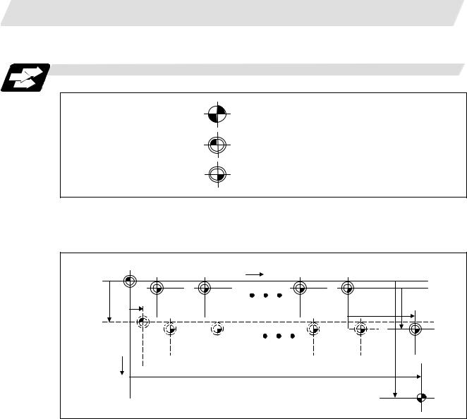
1.2Coordinate Systems and Coordinate Zero Point Symbols
Function and purpose
: Reference position
: Machine coordinate origin
: Workpiece coordinate zero points (G54 to G59)
Upon completion of the reference point return, the parameters are referred to and automatically set for the basic machine coordinate system and workpiece coordinate systems (G54 to G59). The basic machine coordinate system is set so that the first reference point is at the position designated by the parameter from the basic machine coordinate zero point (machine zero point).
Basic machine |
|
Machine zero point |
|
|
|
|
|
coordinate system |
|
+Z |
|
|
|
||
|
|
|
|
|
|
|
|
|
|
Workpiece |
Workpiece |
Workpiece |
Workpiece |
|
|
X2 |
Z2 |
coordinate |
coordinate |
coordinate |
coordinate |
X3 |
|
system |
system |
system |
system6 |
|
|||
|
|
1 (G54) |
2 (G55) |
5 (G58) |
(G59) Z 3 |
|
|
Hypothetical machine |
|
|
|
|
|
|
|
coordinate system |
|
|
|
|
|
|
Local |
(shifted by G92) |
|
|
|
|
|
|
coordinate |
|
|
|
|
|
|
X1 |
system |
|
|
|
|
|
|
(G52) |
|
+X |
|
|
|
|
Z1 |
|
|
|
|
|
|
|
|
|
|
|
|
|
|
|
1st reference position |
|
|
The local coordinate system (G52) is valid on the coordinate systems designated by the commands for the workpiece coordinate systems 1 to 6.
Using the G92 command, the basic machine coordinate system can be shifted and made the hypothetical machine coordinate system. At the same time, workpiece coordinate systems 1 to 6 are also shifted.
2

2. INPUT COMMAND UNITS
2.1 Input Command Units
2. INPUT COMMAND UNITS
2.1Input Command Units
Function and purpose
These are the units used for the movement amounts in the program as commanded by the MDI input. They are expressed in millimeters, inches or degrees (°).
2.2Input Setting Units
Function and purpose
These are the units of setting data which are used, as with the compensation amounts, in common for all axes.
The input command unit can be selected for each axis and input setting units can be selected in common for the axes by parameters from among the following types. (For further details on settings, refer to the sections about control.)
|
|
|
Linear axis |
|
Rotation |
||
|
Type |
Millimeter |
Inch |
axis |
|||
|
Diametrical |
Radial |
Diametrical |
Radial |
(°) |
||
|
|
||||||
|
|
command |
command |
command |
command |
|
|
Input |
#1003 |
0.001 |
0.001 |
0.0001 |
0.0001 |
0.001 |
|
cunit=10 |
|||||||
command unit |
|
|
|
|
|
||
=1 |
0.0001 |
0.0001 |
0.00001 |
0.00001 |
0.0001 |
||
|
|||||||
Min. movement |
IS-B |
0.0005 |
0.001 |
0.0005 |
0.0001 |
0.001 |
|
unit |
IS-C |
0.00005 |
0.0001 |
0.00005 |
0.00001 |
0.0001 |
|
Input setting |
IS-B |
0.001 |
0.001 |
0.0001 |
0.0001 |
0.001 |
|
unit |
IS-C |
0.0001 |
0.0001 |
0.00001 |
0.00001 |
0.0001 |
|
(Note 1) Inch/metric conversion is performed in either of 2 ways: conversion from the Parameter screen ("Initial inch": valid only when the power is turned ON) and conversion using the G command (G20 or G21).
However, when a G command is used for the conversion, the conversion applies only to the input command units and not to the input setting units.
Consequently, the tool offset amounts and other compensation amounts as well as the variable data should be preset to correspond to input setting unit.
(Note 2) The millimeter and inch systems cannot be used together.
3

3. DATA FORMATS
3.1 Tape Codes
3. DATA FORMATS
3.1Tape Codes
Function and purpose
The tape command codes used for this NC are combinations of alphabet letters (A, B, C...Z), numbers (0, 1, 2...9) and signs ( +, –, /...). These alphabet letters, numbers and signs are referred to as characters. Each character is represented by a combination of 8 holes which may, or may not, be present.
These combinations make up what is called codes. This NC employs the ISO code (R-840).
 CAUTION
";", "EOB" and "%" "EOR" are expressions used for the explanation. The actual codes are "line feed" and "%" for ISO.
Detailed description
(1)For the sake of convenience, a ";" has been used in the NC display to indicate End Of Block (EOB/LF) which separates one block from another. Do not use the ";" key, however, in actual programming but use the keys in the following table instead.
EOB/EOR keys and displays
Code used |
ISO |
NC display |
|
Key used |
|||
|
|
||
End Of Block |
LF or NL |
; |
|
End Of Record |
% |
% |
(Note 1) If a code not given in Table of tape codes is assigned during operation, an Illegal address error "P32" will result.
(Note 2) The following codes which exist with ISO can be designated by parameter:
[ |
(left square parenthesis) |
] |
(right square parenthesis) |
# |
(sharp sign) |
|
(asterisk) |
= |
(equals sign) |
:(colon)
!(exclamation mark) = (queuing code)
$ (dollar sign) = (code designating system number)
Any codes which overlap with existing codes or codes which result in parity H cannot be designated.
4
3. DATA FORMATS
3.1 Tape Codes
(2)Significant data section (label skip function)
All data up to the first EOB (;), after the power has been turned ON or after operation has been reset, are ignored during automatic operation based on tape, memory loading operation or during a search operation. In other words, the significant data section of a tape extends from the character or number code after the first EOB (;) code after resetting to the point where the reset command is issued.
(3)Control out, control in
When the ISO code is used, all data between control out "(" and control in ")" are ignored by the NC, although these data appear on the setting display unit. Consequently, the command tape name, number and other such data not directly related to control can be inserted in this section.
This information will also be loaded, however, during tape loading.
The system is set to the "control in" mode when the power is turned ON.
Example of ISO code
FL CRG 0 0 X - 8 5 0 0 0 Y - 6 4 0 0 0 ( CUT T ERSPRE T URN ) FL
• |
• |
•• |
|
|
• |
• |
|
•• |
• |
|
•• |
• |
• |
|
• • • •• |
• |
|||
•• |
•• •• • |
|
|
• |
• |
|
|
|
• |
•••• |
|
• •• • |
|
|
|||||
•• |
•• |
|
|
|
••• |
• |
|
|
|
••• • •• |
|
||||||||
• • • • • • • • • ••• • • |
•••• |
• • • |
•• |
• • • • • |
• • • • • • • • • • • • •••••• • |
|
|||||||||||||
••••• ••• |
|
••• |
|
•••••• |
••••• |
|
|
••• • |
|
• ••• |
•• |
|
|||||||
•••••••••• |
• |
•• |
• |
•••••• |
•••••••• |
•••••• |
• |
••••••• |
|
||||||||||
• |
• •• |
• |
|
• |
|
• |
|
|
• |
|
• |
|
••••• |
••• • • • |
|
|
|||
Operator information print-out example
Information in this section is ignored and nothing is executed.
(4)EOR (%) code
Generally, End Of Record is punched at both ends of the tape. It has the following functions:
(a)Rewind stop when rewinding tape (with tape handler)
(b)Rewind start during tape search (with tape handler)
(c)Completion of loading during tape loading
5

3. DATA FORMATS
3.2 Program Formats
3.2Program Formats
Function and purpose
The prescribed arrangement used when assigning control information to the NC unit is known as the "program format", and the format used with the NC is called the "word address format."
Detailed description
(1)Word and address
A word is a collection of characters arranged in a specific sequence. This entity is used as the unit for processing data and for causing the NC to execute specific operations.
Each word used for the NC consists of an alphabet letter and a number of several digits (sometimes with a "+" or "–" sign placed at the head of the number).
Word


 ------
Numerical (word data)
Alphabet (address)
Word configuration
The alphabet letter at the head of the word is the address. It defines the meaning of the numerical information which follows it.
With the NC, "S =" can be commanded for a multiple number of spindle commands although this applies only to address S.
For details of the types of words and the number of significant digits of numbers used for this NC, refer to Table 1 Format details and abbreviations.
(2)Blocks
A block is a collection of words. It includes the information which is required for the NC to execute one specific operation. One block unit constitutes a complete command. The end of each block is marked with an EOB (End-Of-Block) code.
(3)Programs
A program is a collection of several blocks.
(Note 1) If there is no number after the alphabetic character in the actual program, the value following the alphabetic character will be handled as 0.
(Example) G28XYZ; → G28X0Y0Z0;
6

3. DATA FORMATS
|
|
|
3.2 |
Program Formats |
||||
|
Table 1 Format details and abbreviations |
|
|
|
|
|||
|
|
|
|
|
|
|
||
|
Item |
|
|
Abbreviation |
||||
Program number |
|
|
O8 |
|
|
|
|
|
Sequence number |
|
|
N5 |
|
|
|
|
|
Preparatory function |
|
|
G3/G21 |
|
|
|
|
|
Movement |
Input setting unit |
A 0.01°, mm |
X + 62 |
Z + 62 |
|
|
+ 62 |
|
|
|
|||||||
|
|
|||||||
command |
|
|
|
|
|
|
|
|
Input setting unit |
B 0.001°, mm |
X + 53 |
Z + 53 |
|
|
+ 53 |
||
|
|
|||||||
|
|
|
||||||
|
|
|
|
|
|
|
||
|
Input setting unit |
C 0.0001°, mm |
X + 44 |
Z + 44 |
|
|
+ 44 |
|
|
|
|
||||||
|
|
|
||||||
|
|
|
|
|
|
|
|
|
Movement |
Input setting unit |
A 0.01°, mm |
I + 62 |
K + 62 |
|
|
|
|
command, circular, |
|
|
|
|
|
|
|
|
Input setting unit |
B 0.001°, mm |
I + 53 |
K + 53 |
|
|
|
||
cutter radius |
|
|
|
|||||
Input setting unit |
C 0.0001°, mm |
I + 44 |
K + 44 |
|
|
|
||
|
|
|
|
|||||
Dwell |
Input setting unit |
A 0.01°, mm |
X + 53 |
P8 |
|
|
|
|
|
Input setting unit |
B 0.001°, mm |
X + 53 |
P8 |
|
|
|
|
|
Input setting unit |
C 0.0001°, mm |
X + 53 |
P8 |
|
|
|
|
Feed function |
Input setting unit |
A 0.01°, mm |
F62 (feed per minute) |
|||||
|
|
|
F43 (feed per rotation) |
|||||
|
Input setting unit |
B 0.001°, mm |
F53 (feed per minute) |
|||||
|
|
|
F34 (feed per rotation) |
|||||
|
Input setting unit |
C 0.0001°, mm |
F54 (feed per minute) |
|||||
|
|
|
F25 (feed per rotation) |
|||||
Tool offset |
|
|
T1/T2 |
|
|
|
|
|
Miscellaneous function |
|
M2/M8 |
|
|
|
|
|
|
Spindle function |
|
|
S2/S5/S8 or S |
= n |
|
|
|
|
Tool function |
|
|
T2/T8 |
|
|
|
|
|
2nd miscellaneous function |
|
A8/B8/C8 |
|
|
|
|
||
Subprogram |
|
|
P8H5L4 |
|
|
|
|
|
Fixed cycle |
Input setting unit |
A 0.01°, mm |
R + 62 |
Q62 |
P8 |
|
L4 |
|
|
Input setting unit |
B 0.001°, mm |
R + 53 |
Q53 |
P8 |
|
L4 |
|
|
Input setting unit |
C 0.0001°, mm |
R + 44 |
Q44 |
P8 |
|
L4 |
|
(Note 1) "  " denotes the A, B, C, Y, P or R.
(Note 2) The number of digits in the words is checked by the maximum number of digits in the addresses.
7

3. DATA FORMATS
3.3 Tape Storage Format
3.3Tape Storage Format
Function and purpose
(1)Storage tape and storage sections
The section which is stored into the memory extends from the character following the head EOB after resetting as far as the EOR code.
The significant codes listed in Table of tape codes in Section 3.1 are the codes in the above storage section which are actually stored into the memory. All other codes are ignored and are not stored.
The data between control out "(" and control in ")" are stored into the memory.
3.4Optional Block Skip
Function and purpose
This function selectively ignores specific blocks in a machining program which starts with the "/" (slash) code.
Detailed description
(1)Provided that the optional block skip switch is ON, blocks starting with the "/" code are ignored. They are executed if the switch is OFF.
Parity check is valid regardless of whether the optional block skip switch is ON or OFF. When, for instance, all blocks are to be executed for one workpiece but specific blocks are not to be executed for another workpiece, the same command tape can be used to machine different parts by inserting the "/ " code at the head of those specific blocks.
Precautions for using optional block skip
(1)Put the "/" code at the head of the block. When inserted in a block, this is handled as a division sign.
(Example) N20G1X25./Z25.;............. |
NG |
|
(This will be handled as 25. /0, so the error P283 |
|
"Divided by zero" will occur.) |
/N20G1X25.Z25.;............. |
OK |
(2)Parity checks (H and V) are conducted regardless of the optional block skip switch state.
(3)The optional block skip is processed immediately before the pre-read buffer.
Consequently, it is not possible to skip up to the block which has been read into the pre-read buffer.
(4)This function is valid even during a sequence number search.
(5)AII blocks with the "/" code are also input and output during tape storing and tape output, regardless of the state of the optional block skip switch.
8

3. DATA FORMATS
3.5 Program/Sequence/Block Numbers (O, N)
3.5Program/Sequence/Block Numbers (O, N)
Function and purpose
These numbers are used for monitoring the execution of the machining programs and for calling both machining programs and specific stages in machining programs.
(1)Program numbers are classified by workpiece correspondence or by subprogram units, and they are designated by the address "O" followed by a number with up to 8 digits.
(2)Sequence numbers are attached where appropriate to command blocks which configure machining programs, and they are designated by the address "N" followed by a number with up to 5 digits.
(3)Block numbers are automatically provided inside the NC itself. They are preset to "0" every time a program number or sequence number is read, and they are counted up one at a time unless program numbers or sequence numbers are commanded in blocks which are subsequently read.
Consequently, all the blocks of the machining programs given in the table below can be determined without further consideration by combinations of program numbers, sequence numbers and block numbers.
|
NC input machining program |
NC monitor display |
|
||
|
Program |
Sequence |
|
Block |
|
|
|
No. |
No. |
|
No. |
O12345678 (DEMO.PROG); |
12345678 |
0 |
|
0 |
|
N100 G00 G90 X120. Z100.; |
12345678 |
100 |
|
0 |
|
G94 S1000; |
12345678 |
100 |
|
1 |
|
N102 G71 P210 Q220 I0.2 K0.2 D0.5 F600; |
12345678 |
102 |
|
0 |
|
N200 G94 S1200 F300; |
12345678 |
200 |
|
0 |
|
N210 G01 X0 Z95.; |
12345678 |
210 |
|
0 |
|
G01 |
X20.; |
12345678 |
210 |
|
1 |
G03 |
X50. Z80. K–15.; |
12345678 |
210 |
|
2 |
G01 |
Z55.; |
12345678 |
210 |
|
3 |
G02 |
X80. Z40. I15.; |
12345678 |
210 |
|
4 |
G01 |
X100.; |
12345678 |
210 |
|
5 |
G01 |
Z30.; |
12345678 |
210 |
|
6 |
G02 |
Z10. K–15.; |
12345678 |
210 |
|
7 |
N220 G01 Z0; |
12345678 |
220 |
|
0 |
|
N230 G00 X120. Z150.; |
12345678 |
230 |
|
0 |
|
N240 M02; |
12345678 |
240 |
|
0 |
|
% |
|
12345678 |
240 |
|
0 |
9

3. DATA FORMATS
3.6 G Code System
3.6G Code System
Function and purpose
These numbers are used to monitor the execution status of the machining program, or to call a machining program or a specific process in the machining program.
There are 3 G code systems: 1, 2 and 3. Parameters "G code type 1", "G code type 2" and "G code type 3" are used to set the applicable system.
G code system 3 is an additional specification.
The description of the G functions is based on G code system 2 which serves as the standard.
(Note 1) An alarm results when a G code not listed in the table is commanded. ("P34": Illegal G code)
(Note 2) An alarm results when a G code not included in the additional specifications is commanded.
(Example) An alarm ("P50 No spec: Inch/mm") occurs when the inch command G code (G20) is commanded although the inch/mm specifications have not been provided.
Table of G code systems
|
|
|
|
|
|
|
|
|
|
|
Reference |
|
G code system (standard = 2) |
Group |
Function name |
section in this |
|||||||
|
manual |
||||||||||
|
|
|
|
|
|
|
|
|
|
|
|
|
|
|
|
|
|
|
|
|
|
|
(Section) |
1 |
|
2 |
|
3 |
|
|
|
||||
|
|
G00 |
|
|
G00 |
|
|
G00 |
01 |
Positioning |
6.1 |
|
|
G01 |
|
|
G01 |
|
|
G01 |
01 |
Linear interpolation |
6.2 |
|
|
|
|
||||||||
|
|
|
|
||||||||
|
|
G02 |
|
|
G02 |
|
|
G02 |
01 |
Circular interpolation (clockwise) |
6.3, 6.4 |
|
|
G03 |
|
|
G03 |
|
|
G03 |
01 |
Circular interpolation (counterclockwise) |
6.3, 6.4 |
|
|
G04 |
|
|
G04 |
|
|
G04 |
00 |
Dwell |
8.1, 8.2 |
|
|
|
|
|
|
|
|
|
|
|
|
|
|
|
|
|
|
|
|
|
|
|
|
|
|
G09 |
|
|
G09 |
|
|
G09 |
00 |
Exact stop |
7.8 |
|
|
G10 |
|
|
G10 |
|
|
G10 |
00 |
Data setting |
12.5 |
|
|
G11 |
|
|
G11 |
|
|
G11 |
00 |
Data setting mode cancel |
12.1 |
|
|
|
|
|
|
|
|
|
|
|
|
|
|
G12.1 |
|
|
G12.1 |
|
|
G12.1 |
19 |
Milling mode ON |
6.8 |
|
|
G13.1 |
|
|
G13.1 |
|
|
G13.1 |
19 |
Milling mode OFF |
|
|
|
G14 |
|
|
G14 |
|
|
G14 |
18 |
Balance cut OFF |
17.4 |
|
|
G15 |
|
|
G15 |
|
|
G15 |
18 |
Balance cut ON |
|
|
|
G16 |
|
|
G16 |
|
|
G16 |
02 |
Y-Z cylindrical plane selection |
6.8 |
|
|
G17 |
|
|
G17 |
|
|
G17 |
02 |
X-Y plane selection |
6.5 |
|
|
|
|
||||||||
|
|
|
|
||||||||
|
|
G18 |
|
|
G18 |
|
|
G18 |
02 |
Z-X plane selection |
|
|
|
|
|
|
|||||||
|
|
|
|
|
|||||||
|
|
G19 |
|
|
G19 |
|
|
G19 |
02 |
Y-Z plane selection |
|
|
|
|
|
|
|||||||
|
|
|
|
|
|||||||
|
|
G20 |
|
|
G20 |
|
|
G70 |
06 |
Inch command |
5.3 |
|
|
|
|
||||||||
|
|
|
|
||||||||
|
|
G21 |
|
|
G21 |
|
|
G71 |
06 |
Metric command |
|
|
|
|
|
|
|
||||||
|
|
|
|
|
|
|
|||||
|
|
G22 |
|
|
G22 |
|
|
G22 |
04 |
Barrier check ON |
15.1 |
|
|
G23 |
|
|
G23 |
|
|
G23 |
04 |
Barrier check OFF |
|
|
|
|
|
|
|
|
|
|
|
|
|
|
|
|
|
|
|
|
|
|
|
|
|
|
|
|
|
|
|
|
|
|
|
|
|
10

3. DATA FORMATS
3.6 G Code System
|
|
|
|
|
|
|
|
|
|
|
Reference |
|
G code system (standard = 2) |
Group |
Function name |
section in this |
|||||||
|
manual |
||||||||||
|
|
|
|
|
|
|
|
|
|
|
|
|
|
|
|
|
|
|
|
|
|
|
(Section) |
|
|
G27 |
|
|
G27 |
|
|
G27 |
00 |
Reference point return check |
14.9 |
|
|
G28 |
|
|
G28 |
|
|
G28 |
00 |
Reference point return |
14.7 |
|
|
G29 |
|
|
G29 |
|
|
G29 |
00 |
Return from reference point |
|
|
|
G30 |
|
|
G30 |
|
|
G30 |
00 |
2nd reference point return |
14.8 |
|
|
G31 |
|
|
G31 |
|
|
G31 |
00 |
Skip function |
16.1 |
|
|
G32 |
|
|
G33 |
|
|
G33 |
01 |
Thread cutting |
6.7 |
|
|
G34 |
|
|
G34 |
|
|
G34 |
01 |
Variable lead thread cutting |
|
|
|
G35 |
|
|
G35 |
|
|
G35 |
01 |
Circular thread cutting (CW) |
|
|
|
G36 |
|
|
G36 |
|
|
G36 |
01 |
Circular thread cutting (CCW) |
|
|
|
G37 |
|
|
G37 |
|
|
G37 |
00 |
Automatic tool length offset, automatic tool |
16.3 |
|
|
|
|
|
|
length measurement |
|
||||
|
|
|
|
|
|
|
|
|
|
|
|
|
|
|
|
|
|
|
|
|
|
|
|
|
|
|
|
|
|
|
|
|
|
|
|
|
|
G40 |
|
|
G40 |
|
|
G40 |
07 |
Tool nose R compensation cancel |
12.4 |
|
|
G41 |
|
|
G41 |
|
|
G41 |
07 |
Tool nose R compensation left |
|
|
|
G42 |
|
|
G42 |
|
|
G42 |
07 |
Tool nose R compensation right |
|
|
|
G43 |
|
|
G43 |
|
|
G43 |
08 |
2nd spindle control OFF |
10.6 |
|
|
|
|
||||||||
|
|
|
|
||||||||
|
|
G44 |
|
|
G44 |
|
|
G44 |
08 |
2nd spindle control ON |
|
|
|
|
|
|
|||||||
|
|
|
|
|
|||||||
|
|
G46 |
|
|
G46 |
|
|
G46 |
07 |
Tool nose R compensation |
12.4 |
|
|
|
|
|
|
(automatic selection of direction) ON |
|
||||
|
|
|
|
|
|
|
|
|
|
|
|
|
|
|
|
|
|
|
|
|
|
|
|
|
|
|
|
|
|
|
|
|
|
|
|
|
|
G50 |
|
|
G92 |
|
|
G92 |
00 |
Coordinate system setting |
14.6 |
|
|
|
|
|
|
Spindle clamp speed setting |
10.4 |
||||
|
|
|
|
|
|
|
|
|
|
||
|
|
|
|
|
|
|
|
|
|
|
|
|
|
G52 |
|
|
G52 |
|
|
G52 |
00 |
Local coordinate system setting |
14.11 |
|
|
G53 |
|
|
G53 |
|
|
G53 |
00 |
Machine coordinate system selection |
14.5 |
|
|
G54 |
|
|
G54 |
|
|
G54 |
12 |
Workpiece coordinate system selection 1 |
14.10 |
|
|
G55 |
|
|
G55 |
|
|
G55 |
12 |
Workpiece coordinate system selection 2 |
|
|
|
G56 |
|
|
G56 |
|
|
G56 |
12 |
Workpiece coordinate system selection 3 |
|
|
|
G57 |
|
|
G57 |
|
|
G57 |
12 |
Workpiece coordinate system selection 4 |
|
|
|
G58 |
|
|
G58 |
|
|
G58 |
12 |
Workpiece coordinate system selection 5 |
|
|
|
G59 |
|
|
G59 |
|
|
G59 |
12 |
Workpiece coordinate system selection 6 |
|
|
|
|
|
|
|
|
|
|
|
|
|
|
|
G61 |
|
|
G61 |
|
|
G61 |
13 |
Exact stop check mode |
7.9 |
|
|
|
|
|
|
|
|
|
|
|
|
|
|
|
|
|
|
|
|
|
|
|
|
|
|
G64 |
|
|
G64 |
|
|
G64 |
13 |
Cutting mode |
7.10 |
|
|
G65 |
|
|
G65 |
|
|
G65 |
00 |
Macro call |
13.7.1 |
|
|
G66 |
|
|
G66 |
|
|
G66 |
14 |
Macro modal call A |
|
|
|
G66.1 |
|
|
G66.1 |
|
|
G66.1 |
14 |
Macro modal call B |
|
|
|
G67 |
|
|
G67 |
|
|
G67 |
14 |
Macro modal call cancel |
|
|
|
G68 |
|
|
G68 |
|
|
G68 |
15 |
Facing turret mirror image ON |
13.8 |
|
|
G69 |
|
|
G69 |
|
|
G69 |
15 |
Facing turret mirror image OFF |
|
|
|
|
|
|
|
|
|
|
|
|
|
|
|
G70 |
|
|
G70 |
|
|
G72 |
09 |
Finishing cycle |
13.2.4 |
|
|
G71 |
|
|
G71 |
|
|
G73 |
09 |
Longitudinal rough cutting cycle |
13.2.1 |
|
|
G72 |
|
|
G72 |
|
|
G74 |
09 |
Face rough cutting cycle |
13.2.2 |
|
|
G73 |
|
|
G73 |
|
|
G75 |
09 |
Stock removal in rough cutting cycle |
13.2.3 |
11

3. DATA FORMATS
3.6 G Code System
|
|
|
|
|
|
|
|
|
|
|
Reference |
|
G code system (standard = 2) |
Group |
Function name |
section in this |
|||||||
|
manual |
||||||||||
|
|
|
|
|
|
|
|
|
|
|
|
|
|
|
|
|
|
|
|
|
|
|
(Section) |
|
|
G74 |
|
|
G74 |
|
|
G76 |
09 |
Face cut-off cycle |
13.2.5 |
|
|
G75 |
|
|
G75 |
|
|
G77 |
09 |
Longitudinal cut-off cycle |
13.2.6 |
|
|
G76 |
|
|
G76 |
|
|
G78 |
09 |
Compound thread cutting cycle |
13.2.7 |
|
|
|
|
|
|
|
|
|
|
|
|
|
|
G76.1 |
|
|
G76.1 |
|
|
G76.1 |
09 |
2-system simultaneous thread cutting cycle 1 |
17.13 |
|
|
G76.2 |
|
|
G76.2 |
|
|
G76.2 |
09 |
2-system simultaneous thread cutting cycle 2 |
|
|
|
G80 |
|
|
G80 |
|
|
G80 |
09 |
Hole drilling cycle cancel |
13.3.4 |
|
|
G83 |
|
|
G83 |
|
|
G83 |
09 |
Deep hole drilling cycle 1 (Z axis) |
13.3.1 |
|
|
G79 |
|
|
G83.2 |
|
|
G83.2 |
09 |
Deep hole drilling cycle 2 |
13.4 |
|
|
G84 |
|
|
G84 |
|
|
G84 |
09 |
Tap cycle (Z axis) |
13.3.2 |
|
|
G85 |
|
|
G85 |
|
|
G85 |
09 |
Boring cycle (Z axis) |
13.3.3 |
|
|
|
|
|
|
|
|
|
|
|
|
|
|
G87 |
|
|
G87 |
|
|
G87 |
09 |
Deep hole drilling cycle (X axis) |
13.3.1 |
|
|
G88 |
|
|
G88 |
|
|
G88 |
09 |
Tap cycle (X axis) |
13.3.2 |
|
|
G89 |
|
|
G89 |
|
|
G89 |
09 |
Boring cycle (X axis) |
13.3.3 |
|
|
G90 |
|
|
G77 |
|
|
G20 |
09 |
Longitudinal cutting fixed cycle |
13.1.1 |
|
|
G92 |
|
|
G78 |
|
|
G21 |
09 |
Thread cutting fixed cycle |
13.1.2 |
|
|
G94 |
|
|
G79 |
|
|
G24 |
09 |
Face cutting fixed cycle |
13.1.3 |
|
|
|
|
|
|
|
|
|
|
|
|
|
|
G96 |
|
|
G96 |
|
|
G96 |
17 |
Constant surface speed control |
10.3 |
|
|
|
|
||||||||
|
|
|
|
||||||||
|
|
G97 |
|
|
G97 |
|
|
G97 |
17 |
Constant surface speed control cancel |
|
|
|
|
|
|
|||||||
|
|
|
|
|
|||||||
|
|
G98 |
|
|
G94 |
|
|
G94 |
05 |
Asynchronous feed |
7.3 |
|
|
|
|
||||||||
|
|
|
|
||||||||
|
|
G99 |
|
|
G95 |
|
|
G95 |
05 |
Synchronous feed |
|
|
|
|
|
|
|||||||
|
|
|
|
|
|||||||
|
|
– |
|
|
G90 |
|
|
G90 |
03 |
Absolute value command |
5.1 |
|
|
|
|
||||||||
|
|
|
|
||||||||
|
|
– |
|
|
G91 |
|
|
G91 |
03 |
Incremental value command |
|
|
|
|
|
|
|
||||||
|
|
|
|
|
|
|
|||||
|
|
– |
|
|
G98 |
|
|
G98 |
10 |
Hole drilling cycle initial return |
13.3 |
|
|
– |
|
|
G99 |
|
|
G99 |
10 |
Hole drilling cycle reference point return |
|
|
|
|
|
|
|
|
|
|
|
|
|
|
|
G110 |
|
|
G110 |
|
|
G110 |
00 |
Cross machining command |
17.6 |
|
|
G111 |
|
|
G111 |
|
|
G111 |
00 |
Axis name change |
18.3 |
|
|
G113 |
|
|
G113 |
|
|
G113 |
00 |
Spindle synchronization, tool/spindle |
17.8-17.12 |
|
|
|
|
|
|
synchronization cancel |
|
||||
|
|
|
|
|
|
|
|
|
|
|
|
|
|
G114.1 |
|
|
G114.1 |
|
|
G114.1 |
00 |
Spindle synchronization |
17.8 |
|
|
G114.2 |
|
|
G114.2 |
|
|
G114.2 |
00 |
Tool/spindle synchronization 1 (polygon |
17.9 |
|
|
|
|
|
|
machining) |
|
||||
|
|
|
|
|
|
|
|
|
|
|
|
|
|
G114.3 |
|
|
G114.3 |
|
|
G114.3 |
00 |
Tool/spindle synchronization 2 (hobb |
17.10 |
|
|
|
|
|
|
machining) |
|
||||
|
|
|
|
|
|
|
|
|
|
|
|
|
|
G115 |
|
|
G115 |
|
|
G115 |
00 |
Waiting at designated start point 1 |
17.2 |
|
|
G116 |
|
|
G116 |
|
|
G116 |
00 |
Waiting at designated start point 2 |
17.3 |
|
|
G117 |
|
|
G117 |
|
|
G117 |
00 |
Miscellaneous function output during axis |
18.1, 18.2 |
|
|
|
|
|
|
movement |
|
||||
|
|
|
|
|
|
|
|
|
|
|
|
|
|
G125 |
|
|
G125 |
|
|
G125 |
00 |
Control axis synchronization |
17.7 |
|
|
G126 |
|
|
G126 |
|
|
G126 |
00 |
Control axis superimposition |
17.11 |
|
|
|
|
|
|
|
|
|
|
|
|
|
|
G164 |
|
|
G164 |
|
|
G164 |
00 |
Spindle superimposition |
17.12 |
|
|
|
|
|
|
|
|
|
|
|
|
|
|
G173 |
|
|
G173 |
|
|
G173 |
00 |
Inclined coordinate rotation control |
13.16 |
|
|
|
|
|
|
|
|
|
|
||
|
|
G200 to |
|
|
G200 to G999 |
|
G macro call |
18.3 |
|||
12

3. DATA FORMATS
3.6 G Code System
(Note 1) The "  " mark denotes a G code which is selected within each group when the power is turned ON or when resetting that initializes the modal commands is executed.
(Note 2) The "  " mark denotes a G code for which a parameter can be selected as the initial status when the power is turned ON or when resetting that initializes the modal commands is executed. Note that the inch/metric conversion can be made only when the power is turned ON.
 CAUTION
The commands with "no value after G", will be handled as "G00" during operation.
13

3. DATA FORMATS
3.7 Precautions Before Machining
3.7Precautions Before Machining
Precautions before machining
 CAUTION
Before starting actual machining, always carry out dry operation to confirm the machining program, tool offset amount and workpiece offset amount, etc.
When creating the machining program, select the appropriate machining conditions, and make sure that the performance, capacity and limits of the machine and NC are not exceeded. The examples do not consider the machining conditions.
14
Loading...