

Page 1
Page 2

Page 3

MELDAS is a registered trademark of Mitsubishi Electric Corp or at ion .
Other company and product names that appear in this manual are trademarks or registered
trademarks of their respective companies.
Page 4

Page 5

Introduction
Thank you for selecting the Mitsubishi numerical control unit. This instruction manual describes the handling and
caution points for using MS Configurator. Incorrect handling may lead to unforeseen accidents, so always read
this instruction manual thoroughly to ensure correct usage.
Notes on Reading This Manual
(1) Since the description of this specification manual deals with NC in general, for the specifications of
individual machine tools, refer to the manuals issued by the respective machine tool builders. The
"restrictions" and "available functions" described in the manuals issued by the machin e t oo l bu ilde rs ha ve
precedence to those in this manual.
(2) This manual describes as many special operations as possible, but it should be kept in mind that items not
mentioned in this manual cannot be perform ed .
Page 6

Page 7
Precautions for safety
DANGER
WARNING
CAUTION
DANGER
WARNING
Please read this manual and auxiliary documents before starting installation, operation, maintenance or
inspection to ensure correct usage. Thoroughly understand the device, safety information and precautions
before starting operation.
When there is a potential risk of fatal or serious injuries if handling is mistaken.
When a dangerous situation, or fatal or serious injuries may occur if handling is
mistaken.
When a dangerous situation may occur if handling is mistaken leading to
medium or minor injuries, or physical damage.
Note that some items described as " CAUTION" may lead to major results depending on the situation. In any
case, important information that must be observed is described.
Not applicable in this manual.
Not applicable in this manual.
!
Page 8
Do not fail to confirm the soft limit movement (over travel) to prevent collision. Be careful of the
CAUTION
!
position of other axes and pay attention when the cutter has already mounted as the collision
possibly occurs before the soft limit.
When a large vibration occurs because of increasing the speed loop g ain and so on, immediately
!
apply emergency stop to stop the vibration. The machine or servo amplifier could fail if vibration is
generated for a long time.
Do not set the notch filters to the frequency where vibration does not occur. The automatic
!
adjustment might not be executed correctly, or the vibration might be caused.
Set the same position loop gain (PGN1, PNG2, SHGC) to all the interpolation axes. (The
!
parameters (PGN1, PGN2, SHGC) are tuned to the minim u m se ttin g of adjusted axis assistant.)
Set the same time constant to all the interpolation axes. (The time constant is tuned to the
!
maximum setting of adjusted axis assistant.)
When enabling disturbance observer, lost motion compensation has to be adjusted again.
!
Restart the MS Configurator to validate IP address changing.
!
Neither the linear motor nor the direct drive motor correspond.
!
Page 9

Contents
1 Introduction.................................................................... 1
1.1 Outline of MS Configurator ................................................................................................................... 2
1.2 Applicable Model And Version....................................... ....................................... ... ... .... ... ... ................ 4
2 Installation and Setup.................................................... 7
2.1 Operation Environment............................ ... ... ... ... .... ... ....................................... ... ... ... .... ...................... 8
2.2 Procedure of the First Installation.. ... ... ................................................................................................. 8
2.3 Installation Procedure When Upgrading ............................................................................................. 10
2.4 Procedure of Uninstalling................................................................................................................... 10
2.4.1 Procedure of Uninstalling by the Control Panel.......................................................................... 10
2.4.2 Procedure of Uninstalling by the MS Configurator.exe............................................................... 12
2.5 Connection Diagram.......................................................................................................................... 13
3 How to Use.................................................................... 15
3.1 Preparation (Connect with NC).......................................................................................................... 16
3.1.1 Preparation for PC..................................................................................................................... 16
3.1.2 Parameter Setting...................................................................................................................... 16
3.1.3 Other Preparations/Precautions................................................................................................. 22
3.1.4 Starting MS Configurator ................................................................... ... .... ... ... ... .... ...... ... ........... 23
3.1.5 Screen Transition....................................................................................................................... 24
3.1.6 Close the Application................................................................................................................. 24
3.2 Environment Setup ............................................................................................................................ 25
3.2.1 Communication Path Setup........................................................................................................ 25
3.2.2 Vibration Signal Setup ..................................................... ... ... .... ... ... ... ........................................ 27
3.2.3 Program Creation....................................................................................................................... 30
3.3 Assistance Function......................... ... .... ... ... ... ... .... ...................................... .... ... ... ... ........................ 44
3.3.1 Parameter Setup......................................................................................................................... 44
3.4 Servo Automatic Adjustment............... .... ... ... ....................................... ... ... ... .... ... ... ........................... 45
3.4.1 Package Adjustment................................................................................................................... 45
3.4.2 Initial Notch Filter Setup.............................................................................................................. 57
3.4.3 Velocity Loop Gain Adjustment................................................................................................... 58
3.4.4 Time Constant Adjustment.......................................................................................................... 60
3.4.5 Position Loop Gain Adjustment........................................... ... .... ... ...... ... .... ... ... ... .... ... ... ... ... ........ 63
3.4.6 Lost Motion Adjustment Type 3 .................................................................................................. 66
3.4.7 Lost Motion Adjustment .............................................................................................................. 68
3.5 Measurement Function....... ....................................... ... ... .... ... ... ... ..................................................... 71
3.5.1 Frequency Response Measurement (Servo).............................................................................. 71
3.5.2 Frequency Response Measurement of Machine (Servo) .......................................................... 81
3.5.3 Waveform Measurement Function (Program Creation Function) .............................................. 82
3.5.3.1 Chronological Data Measurement..................................................................................... 85
3.5.3.2 Arc Shape Error Measurement........ ... .... ... ... ... .... ...... ... .... ... ... ... ... .... ... ... ... .... ... ... ... ... .... .... 88
3.5.3.3 Synchronous Tapping Error Measurement........................................................................ 91
3.5.3.4 Aarbitrary Path Measurement . ... ... ... ... .... ...... ... .... ... ... ... .... ... ... ... ... .... ... ... ... .... ... ...... ... .... .... 94
3.6 Graph Function of Tools .................................... .... ... ... ... ....................................... ... .... .................... 97
3.6.1 Configuration of Screens ........................................................................................................... 97
3.6.2 How to Use the Graph .............................................................................................................. 101
3.6.3 Method of Saving/Displaying the Data..................................................................................... 113
3.6.4 Method of Printing.................................................................................................................... 117
Page 10

4 Precautions ................................................................ 119
4.1 Precautions for Using Automatic Adjustment Function.................................................................... 120
4.2 Precautions for Using Measurement Function.................................................................................. 122
5 Appendix..................................................................... 125
5.1 Message of Automatic Adjustment................................................................................................... 126
5.2 Message of Measurement Function................................................................................................. 130
5.3 Message of Graph Function ...................................... .... ... ... ... .... ... ....................................... ............. 136
Page 11

付録
1
章
1
Introduction
1
Page 12
1 Introduction
MITSUBISHI CNC
1.1 Outline of MS Configurator
Cable H200
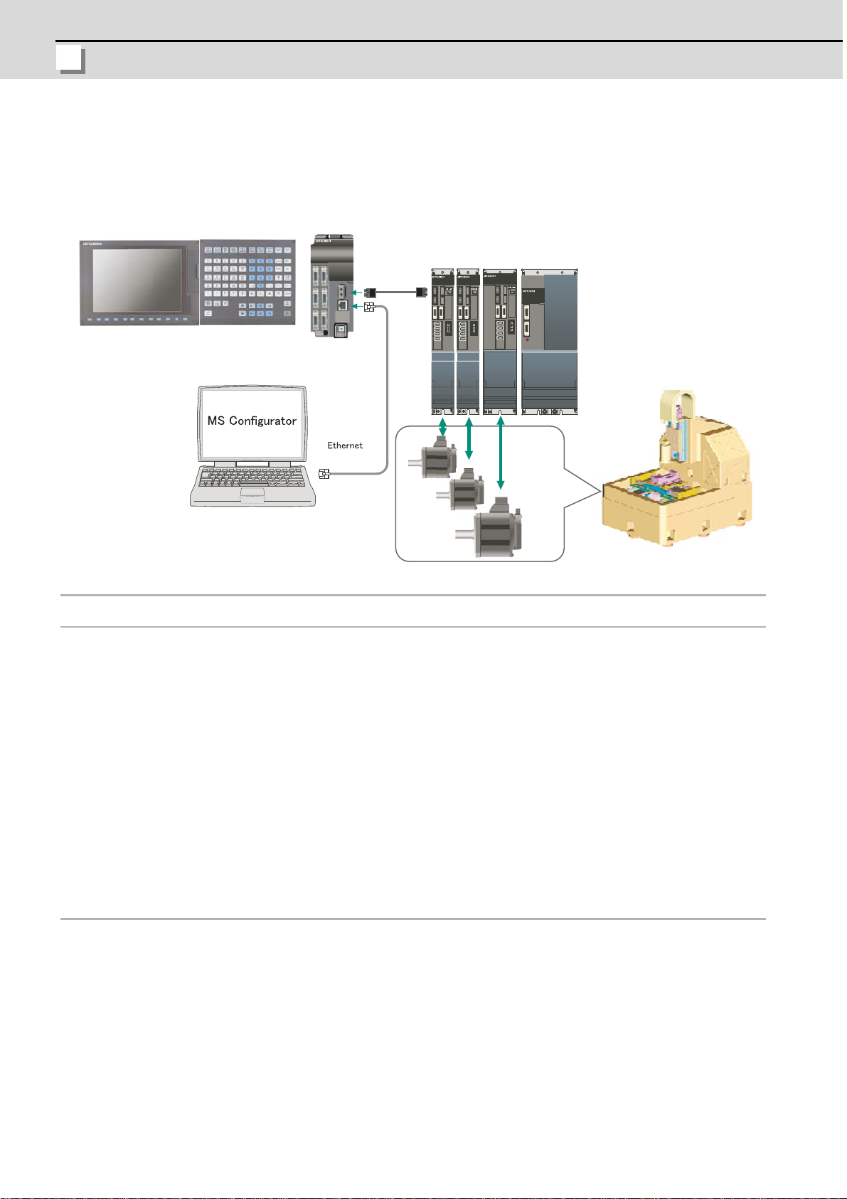
With MS Configurator, the servo parameters can be automatically adjusted by activating the motor
with machining programs for adjustment or vibration signals, and measuring/analyzing the machine
characteristics. And the data measurement function is supported, too.
<Function>
Automatic adjustment function
Package adjustment : Executes three basic automatic adjustments (speed loop gain adjustment,
time constant adjustment, position loop gain adjustment) in a batch.
Initial notch filter setup : Automatically adjusts the notch filter when the initial resonance is large.
Velocity loop gain
: Automatically adjusts the notch filter and the speed loop gain.
adjustment
Time constant adjustment : Automatically adjusts the acceleration/deceleration time constant.
Position loop gain
: Automatically adjusts the position loop gain.
adjustment
Lostmotion adjustment : Automatically adjusts the quadrant protrusion amount of the designated
axis.
Lostmotion 3 adjustment : Automatically adjusts the lost motion type 3 for the quadr ant protrusion
amount of the designated axis.
Measurement function
Frequency response
measurement
Frequency response
measurement of machine
Measurement function
(with program creation
function)
: Measures the frequency response (speed command - speed FB) of speed
loop for the designated axis.
: Measures the frequency response (torque command - speed FB) of
machine system for the designated axis.
: Measures the Chronological data measurement, Arc shape error
measurement, Synchronous tapping error measurement, Measuring
arbitrary path.
2
Page 13

MS Configrator
1.1 Outline of MS Configurator
Adjustment setup function
Communication path
setup
: Sets the path to communicate with NC. The model of connected NC is
selected.
Vibration signal setup : Adjusts the amount of vibration signals used in the velocity loop gain
adjustment or in measuring the frequency response.
Program creation : Creates machining programs for adjustment.
Assistance function
Parameter setup : Saves/changes the servo parameters.
3
Page 14
1 Introduction
MITSUBISHI CNC
1.2 Applicable Model And Version
The model and the version of the CNC and drive unit which can use this software are as follows.
700/70 Series E0 version or later C70 Series A2 version or late r
Servo drive unit
Spindle drive unit
MDS-D/DH-V1/V2
MDS-D-SVJ3
MDS-D/DH-SP
MDS-D-SPJ3
(Note 1) 700/70 Series does not correspond to spindle/PLC axis/parallel synchronous co ntrol axis.
(Note 2) C70 series can be applied to the MS Configurator (BND-1201W000-) A2 version or later.
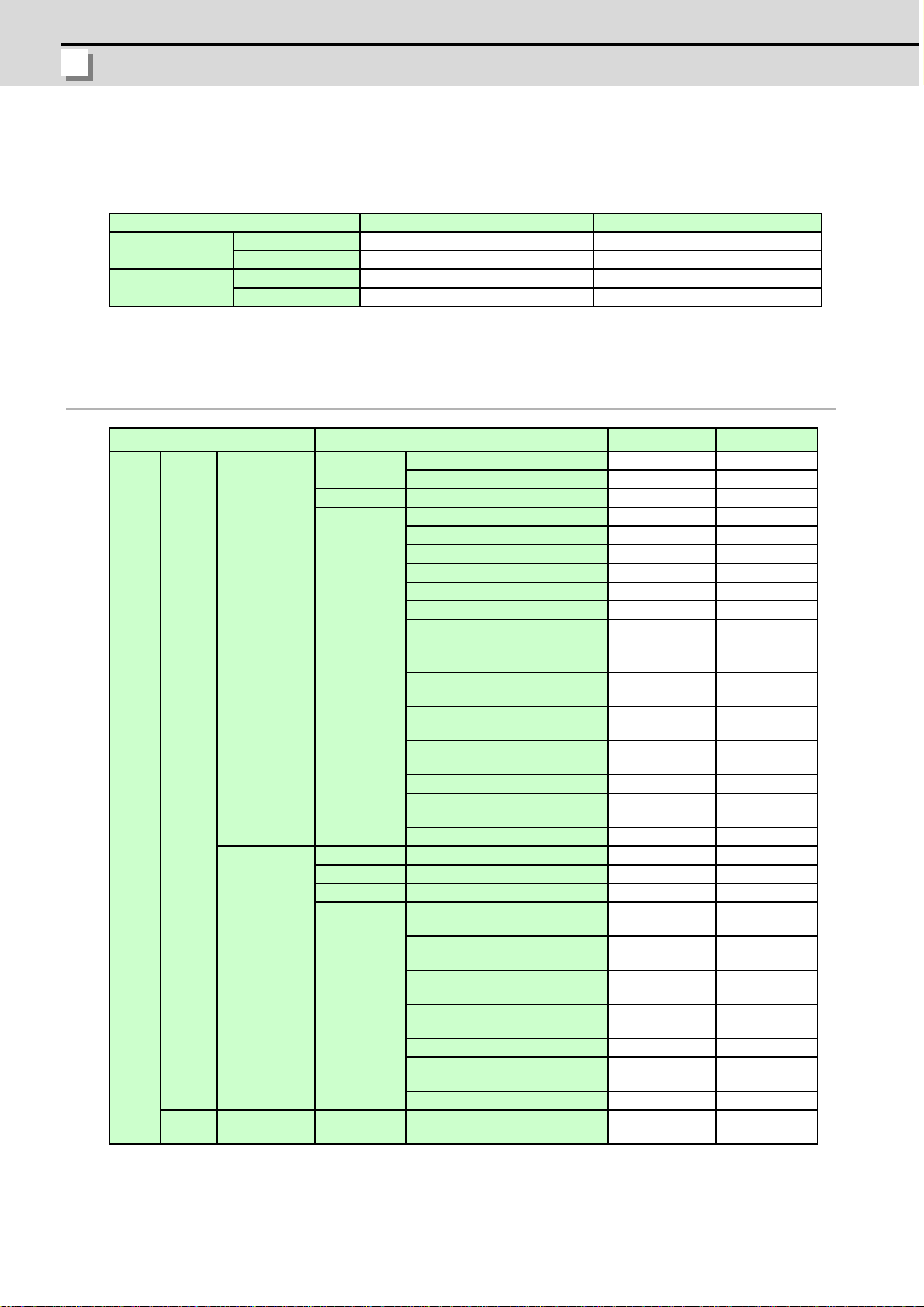
Correspondence function list for each NC (servo)
Environment
Assistance Parameter setup
Adjustment
Singular axis
Measurement
Basec
Servo
axis
Environment Vibration signal setup
Assistance Parameter setup
Adjustment Initial notch filter setup
Parallel
synchronous
control axis
PLC axis - Measurement
Measurement
BND1501W001-A6 or later BND1501W001-A6 or later
BND1501W005-A1 or later BND1501W005-A1 or later
--- BND1501W002-AA or later
--- BND1501W006-A1 or later
Function 700/70 Series C70 Series
Vibration signal setup
Program creation
Package adjustment
Initial notch filter setup
Velocity loop gain adjustment
Time constant adjustment
Position loop gain adjustment
Lostmotion adjustment
Lostmotion type 3 adjustment
Frequency response
measurement
Frequency response
measurement of machine
Program creation for
measurement
Chronological data
measurement
Arc shape error measurement
Synchronous tapping error
measurement
Arbitrary path measurement
Frequency response
measurement
Frequency response
measurement of machine
Program creation for
measurement
Chronological data
measurement
Arc shape error measurement
Synchronous tapping error
measurement
Arbitrary path measurement
Chronological data
measurement
OO
OO
OO
OO
OO
OO
OO
OO
OO
OO
OO
OO
OO
OO
OO
OO
OO
- O (Note 1)
-O
-O
- O (Note 1)
- O (Note 1)
- O (Note 2)
-O
-O
-O
-O
- O (Note 3)
(Note 1) Only a primary axis can be selected. The graphical display is only a primary axis though a
primary axis and a secondary axis are vibrated at the same time when measuring.
(Note 2) Select a primary axis usually when the program for the measurement is created.
4
Page 15

MS Configrator
1.2 Applicable Model And Version
(Note 3) On program creation for measurement screen, only the chronological data measurement
as a measurement item and the reciprocation acceleration/deceleration as th e type can be selected.
However, the program for the measurement is not created, so search the machining program on NC
side.
(Note 4) Neither the linear motor nor the direct drive motor correspond.
(Note 5) This function does not correspond to inch system.
Correspondence function list for each NC (spindle)
Function 700/70 Series C70 Series
- O (Note 1)
--
Spindle
Non-interpolation control (Spindel)
Interpolation control (Spindel C
axis/spindle synchronous)
Measurement
Chronological data
measurement
(Note 1) On program creation for measurement screen, only the chronological data measurement
as a measurement item and the reciprocation acceleration/deceleration as the type can be
selected. However, the program for the measurement is not crea ted, so search the machining
program on NC side.
(Note 2) The spindle does not correspond to the gear ratio.
5
Page 16

1 Introduction
MITSUBISHI CNC
6
Page 17

付録
2
章
2
Installation and Setup
7
Page 18
2 Installation and Setup
MITSUBISHI CNC
2.1 Operation Environment
MS Configurator operates in the following personal computer environments.
- Operating system : WindowsXP/Windows2000
- Language : English/Japanese (Note 1)
- RAM : 256MB or larger recommended
- Display : VGA (640 x 480) or more video graphics adaptor and monitor
- Ethernet port
(Note 1) Japanese is selected for Japanese-language version of Windows. English is selected for other
than Japanese-language version of Windows.
(Note 2) This tool can be used only by the administrator authority.
2.2 Procedure of the First Installation
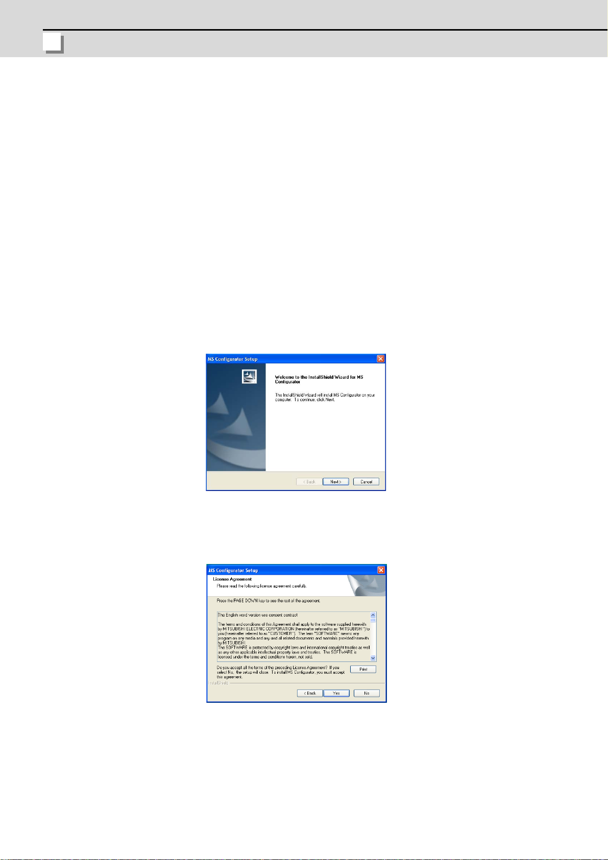
(1) Double-click the MS Configurator.exe.
The setup screen is displayed. Press the "Next" button.
(2) The software license agreement is displayed.
Read the software license agreement carefully, and press the "Yes" button.
If "No" is selected (when you do not agree this agreement), the installation of MS Configurator is
discontinued.
8
Page 19
MS Configrator
2.2 Procedure of the First Installation
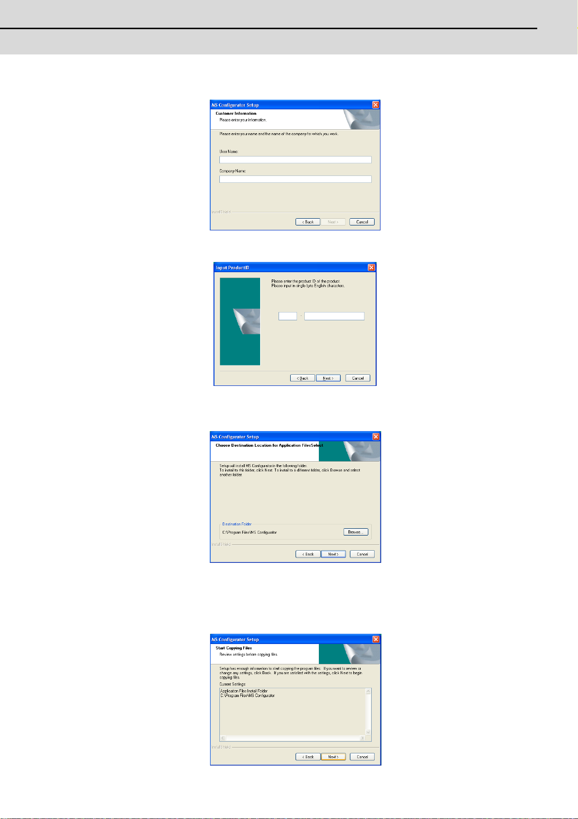
(3) The Costomer Information screen is displayed.
Input user name and company name and press the "Next" button.
(4) Input the product ID on the Input productID screen, and press the "Next" button.
(5) The Choose Designation Location screen is displayed.
Press "Browse" and select the installation destination when changing the installation destination.
Press the "Next" button after the installation destination settings.
(6) The installation destination information is displayed. Press the "Next" button after confirming the installation
destination settings.
(When the setting is changed, press the "Back".)
The setup starts.
9
Page 20
2 Installation and Setup
MITSUBISHI CNC
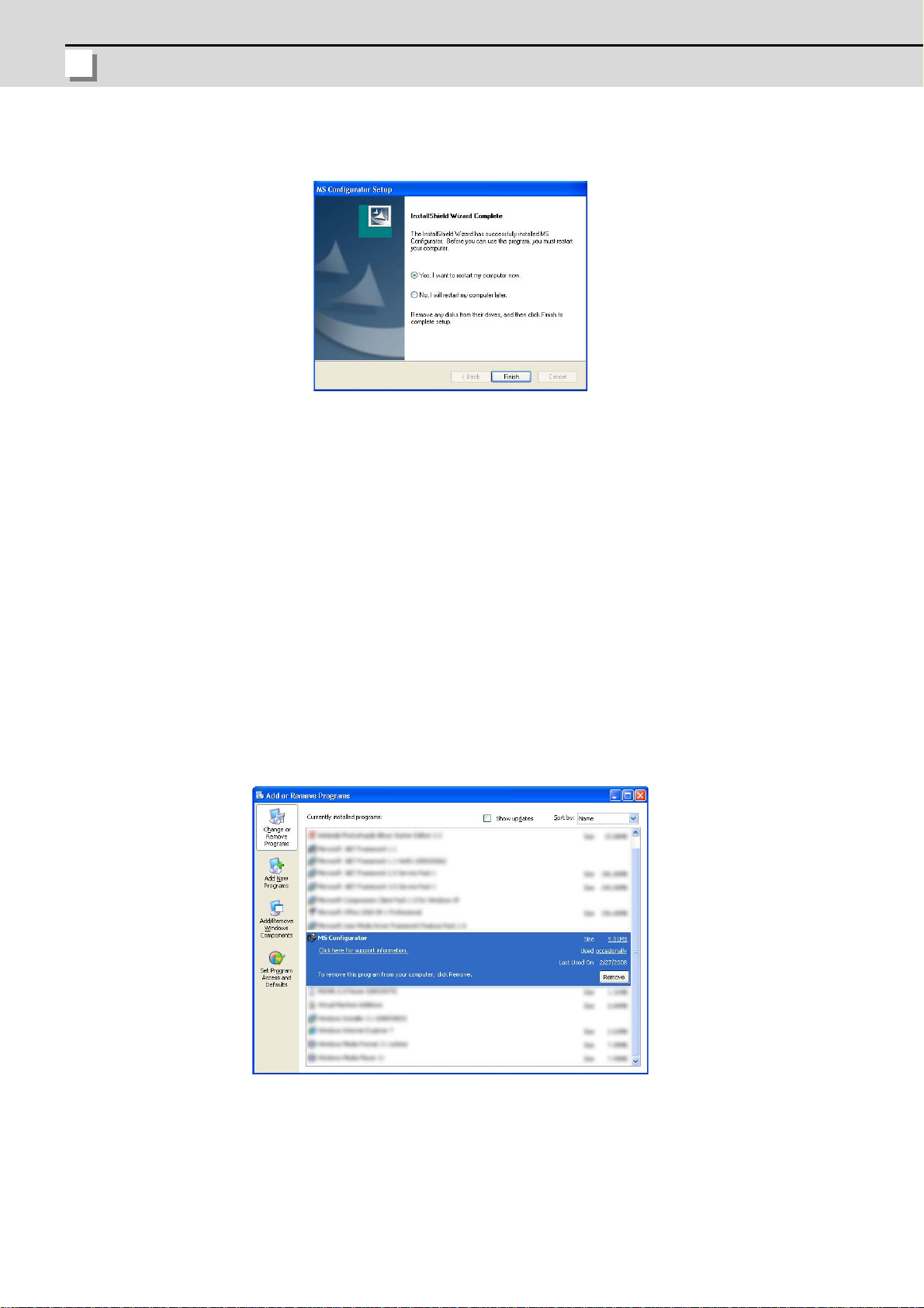
(7) When the installation is correctly completed, the complete screen is displayed.
When "Finish" button is pressed, the installation completes.
2.3 Installation Procedure When Upgrading
When the old version has already been installed, install the new version after uninstalling the old version.
2.4 Procedure of Uninstalling
The MS Configurator has two procedures of uninstalling: executing from the control panel, double-clicking
MS Configurator.exe.
2.4.1 Procedure of Uninstalling by the Control Panel
(1) Select the [Start] - [Control Panel] - [Add or Remove Programs].
The "Add or Remove Programs" screen is displayed.
Select the MS Configurator from the list, and press the "Remove".
10
Page 21
MS Configrator
2.4 Procedure of Uninstalling
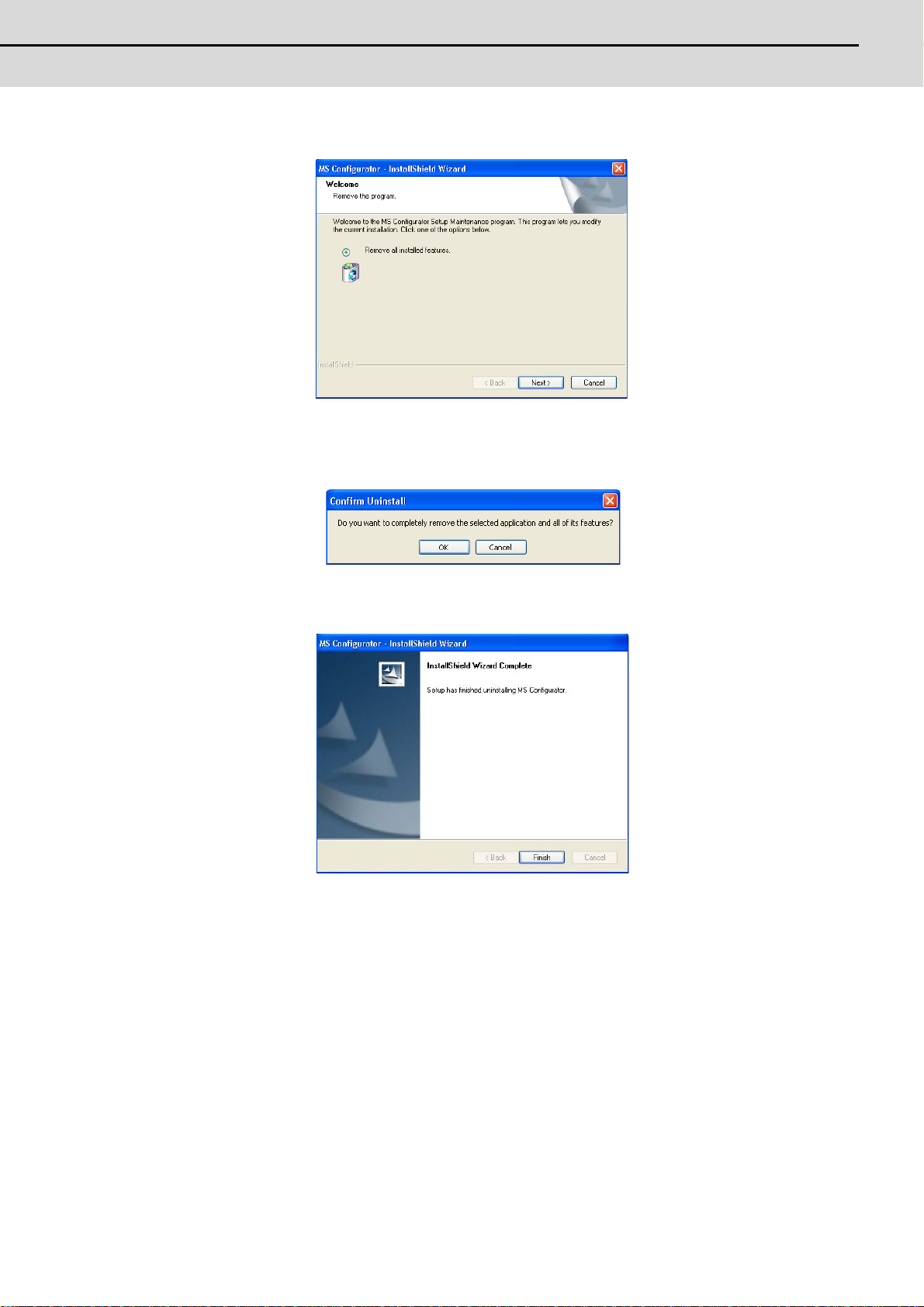
(2) The "InstallShield Wizard" screen is displayed.
Select the "Remove" and press the "Next".
(3) The "Confirm Uninstall" screen is displayed.
When the "OK" is pressed, the uninstallation starts.
(When the "Cancel" is pressed, return to the "InstallShield Wizard" screen .)
(4) When the uninstallation is finished, the complete screen is displayed.
When "Finish" button is pressed, the uninstallation completes.
11
Page 22
2 Installation and Setup
MITSUBISHI CNC
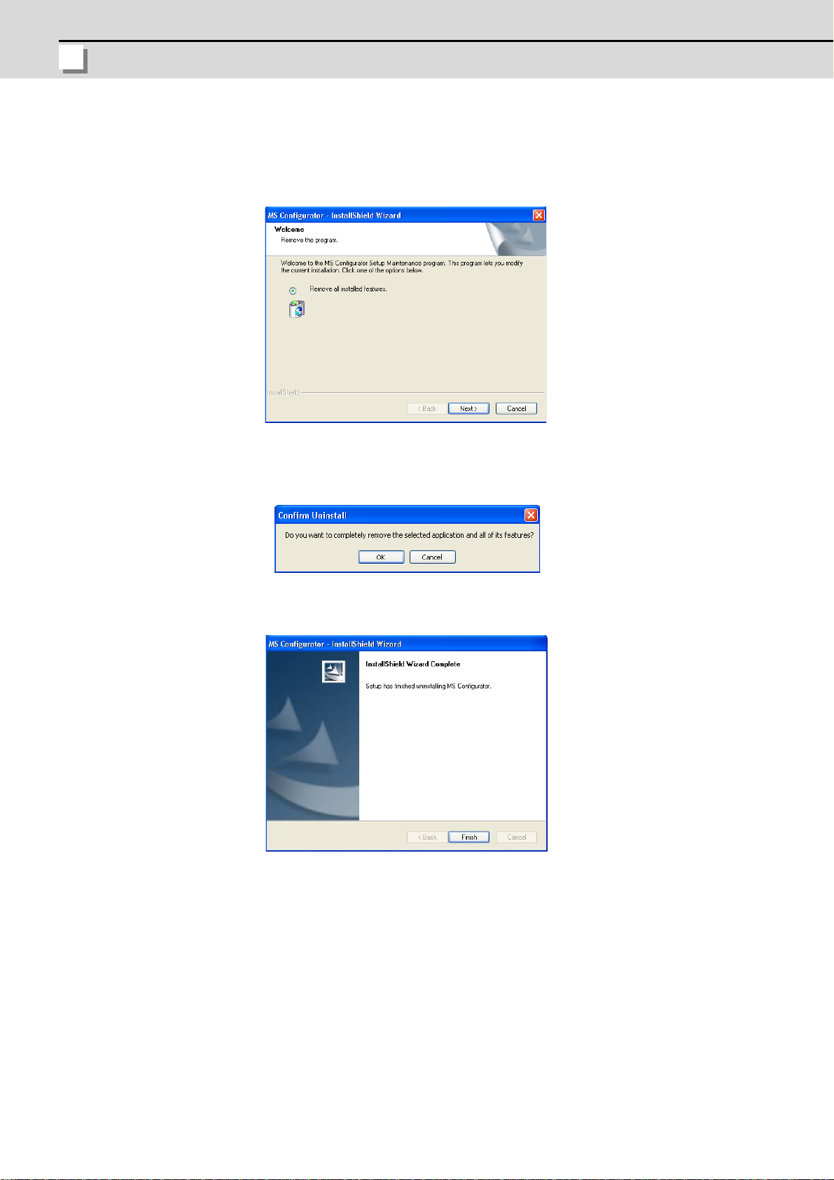
2.4.2 Procedure of Uninstalling by the MS Configurator.exe
(1) Double-click the MS Configurator.exe.
The "Add or Remove Programs" screen is displayed.
The "InstallShield Wizard" screen is displayed.
Press the "Next" button.
(2) The "Confirm Uninstall" screen is displayed.
When the "OK" is pressed, the uninstallation starts.
(When the "Cancel" is pressed, return to the "InstallShield Wizard" screen .)
(3) When the uninstallation is finished, the complete screen is displayed.
When "Finish" button is pressed, the uninstallation completes.
12
Page 23
MS Configrator
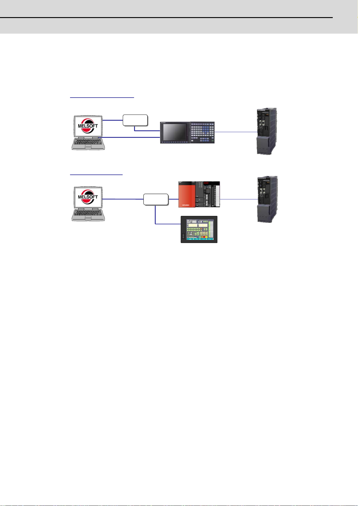
2.5 Connection Diagram
2.5 Connection Diagram
Drive unit
When C70 series
When 700/70 series
NC
PC
HUB
NC
GOT
GOT1000
Drive unit
(
)
cable)
PC
HUB
cable)
The connection diagrams with the 700/70 Series and C70 series are shown below.
(Straight cable)
(Optical
Cross cable
communication
(Straight cable)
(Optical
communication
13
Page 24

2 Installation and Setup
MITSUBISHI CNC
14
Page 25

付録
3
章
3
How to Use
15
Page 26
3 How to Use
MITSUBISHI CNC
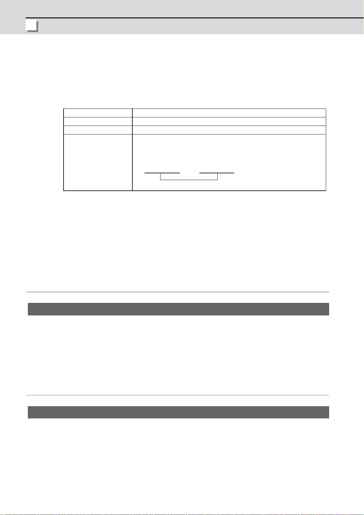
3.1 Preparation (Connect with NC)
(Example)
NC IP adress Personal computer IP address
192.168.200.5 192.168.200.7
Same group
Prepares the following items before MS Configurator is used.
3.1.1 Preparation for PC
Item Details
Cross cable Personal computer is connected to NC with LAN cable.
MS Configurator Install the MS Configurator.
IP address setting Set IP address of personal computer to the same group as the IP
address of NC which is set to "#1926 Global IP address".
3.1.2 Parameter Setting
Correctly set the following parameters before the adjustment is started.
(1) NC parameters
Refer to "700/70 Setup Manual" for parameter details.
Parameter of MS Configurator (Base specifications pa rameter)
【#1164(PR)】 ATS Automatic tuning function
Select whether to enable or disable the automatic tuning function.
0: Disable
1: Enable
(Note 1) When the MS Configurator is used, enable this parameter.
(Note 2) With C70 series, after this parameter is set, this function is instant ly enabled.
Base specifications parameters
【#1013(PR)】 axname Axis name
Set each axis’s name with an alphabetic character.
Use the characters X‚ Y‚ Z‚ U‚ V‚ W‚ A‚ B or C.
(Note 1) Do not set the same name twice in one part system. The same name which is used in
(Note 2) The PLC name does not need to be set. (The axis name is displayed as 1 and 2.)
---Setting range---
X, Y, Z, U, V, W, A, B, C
another part system can be set.
16
Page 27

MS Configrator
3.1 Preparation (Connect with NC)
【#1037(PR)】 cmdtyp Command type
Set the G code list and compensation type for programs.
1 : List1(for M) Type A(one compensation amount for one compensation No.)
2 : List1(for M) Type B(shape and wear compensation amounts for one compensation No.)
3 : List2(for L) Type C(shape and wear compensation amounts for one compensation No.)
4 : List3(for L) Ditto
5 : List4(for special L) Ditto
6 : List5(for special L) Ditto
7 : List6(for special L) Ditto
8 : List7(for special L) Ditto
9 : List8(for M)
M2 form at type A Type A(one compensation amount for one compensation No.)
10 : List8(for M)
M2 form at type B Type B(shape and wear compensation amounts for one compensation No.)
There are some items in the specifications that can be used or cannot be used according to the
value set in this parameter.
The file structure may also change depending on the compensation data type.
(Note) The setting range of C70 series: 1 to 8
【#1076】 Abslnc ABS/INC address (for L system only)
Select the command method for the absolute and incremental commands.
0: Use G command for the absolute and incremental commands.
1: Use axis name for the absolute and incremental commands.
(The axis name in "#1013 axname" will be the absolute command, "#1014 incax" will be the
incremental command.)
【#1219】 aux03
【#1224】 aux08
When "1" is selected, using two axis names, one each for the absolute and incremental commands,
allows to issue the absolute and incremental commands appropriately to an axis.
bit1: Stop high-speed PC monitoring function
Set "1" to disable the function that triggers the emergency stop when the PC high-speed processing
time is extended.
Disable the monitoring function only as a temporary measure.
bit7: Time constant setting changeover for soft acceleration/deceleration
Select the time constant for soft acceleration/deceleration.
0: Accelerating time is obtained with G0tL (G1tL).
1: Accelerating time is obtained with G0tL + G0t1 (G1tL + G1t1).
bit0: Sampling data output
Select whether to enable the sampling da ta output.
0: Disable
1: Enable
17
Page 28

3 How to Use
MITSUBISHI CNC
【#1267(PR)】 ext03
bit0: G code type
Select the high-speed high-accuracy G code type.
0: Conventional format (G61.1)
1: MITSUBISHI special format (G08P1)
【#1926(PR)】 Global IP address IP address
Set the main CPU's IP address.
Set the NC IP address seen from an external source.
Axis specifications parameters
【#2001】 rapid Rapid traverse rate
Set the rapid traverse feedrate for each axis.
(Note) The maximum value to be set depends on the machine specifications.
---Setting range---
1 to 1000000 (mm/min)
【#2002】 clamp Cutting feedrate for clamp function
Set the maximum cutting feedrate for each axis.
Even if the feedrate in G01 exceeds this value, the clamp will be applied at this feedrate.
---Setting range---
1 to 1000000 (mm/min)
18
Page 29

MS Configrator
3.1 Preparation (Connect with NC)
【#2003(PR)】 smgst Acceleration and deceleration modes
Set acceleration and deceleration control modes.
(Note) Set "0" in null bits (excluding bit2 and bit6 when the soft acceleration/deceleration is
<Combination of acceleration/deceleration patterns and bit patterns>
(1)Rapid traverse acceleration/deceleration type
(2)Cutting feed acceleration/deceleration type
(Note) R1 > R3 when both R1 and R3 contain 1.
<Stroke end stop types>
selected.)
bit3,2,1,0 = 0000 : Step
bit3,2,1,0 = 0001 : Linear acceleration/deceleration
bit3,2,1,0 = 0010 : Prim ary delay
bit3,2,1,0 = 1000 : Exponential acceleration and linear deceleration
bit3,2,1,0 = 1111 : Soft acceleration/deceleration
bit7,6,5,4 = 0000 : Step
bit7,6,5,4 = 0001 : Linear acceleration/deceleration
bit7,6,5,4 = 0010 : Prim ary delay
bit7,6,5,4 = 1000 : Exponential acceleration and linear deceleration
bit7,6,5,4 = 1111 : Soft acceleration/deceleration
bitA,9 = 00 : Linear deceleration
bitA,9 = 01 : Posision loop step stop
bitA,9 = 10 : Speed loop step stop
bitA,9 = 11 : Position loop step stop
(Note) OT1 is valid under the following conditions (valid for dog type zero point return):
- Stop type: Linear deceleration
- Acceleration/Deceleration mode: Exponential acceleration and Linear deceleration
---Setting range---
0/1
【#2011】 G0back G0 backlash
Set up the backlash compensation amount when the direction is reversed with the movement
command in rapid traverse feed mode or in manual mode.
---Setting range---
-9999999 to 9999999
【#2012】 G1back G1 backlash
Set up the backlash compensation amount when the direction is reversed with the movement
command in cutting mode.
---Setting range---
-9999999 to 9999999
19
Page 30
3 How to Use
MITSUBISHI CNC
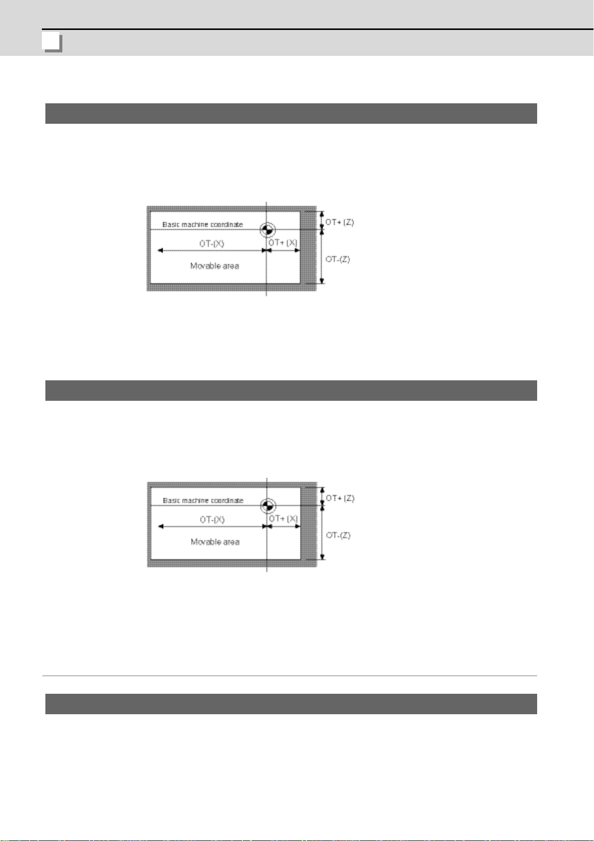
【#2013】 OT - Soft limit I –
Set a soft limit area with reference to the zero poi nt of the basic machine coordinate. Set the
coordinate in the negative direction for the movable area of stored stroke limit 1. The coordinate in
the positive direction is set in "#2014 OT+".
To narrow the available range in actual use, use the parameters "#8204 OT-" and "#8205 OT+".
When the same value (other than "0") is set in this parameter and "#2014 OT+", this function will be
disabled.
---Setting range---
±99999.999 (mm)
【#2014】 OT + Soft limit I +
Set a soft limit area with reference to the zero poi nt of the basic machine coordinate. Set the
coordinate in the positive direction for the movable area of stored stroke limit 1. The coordinate in the
negative direction is set in "#2013 OT-".
To narrow the available range in actual use, use the parameters "#8204 OT-" and"#8205 OT+".
When the same value (other than "0") is set in this parameter and "#2013 OT-", this function will be
disabled.
---Setting range---
±99999.999 (mm)
Machine error compensation
【#4006】 sc Compensation scale factor
Set the scale factor for the compensation amount.
---Setting range---
0 to 99
20
Page 31

MS Configrator
3.1 Preparation (Connect with NC)
(2) Servo parameters
Set the initial parameters according to the specifications of motor, detector, gears, etc.
Refer to "MDS-D/DH Series Instruction Manual" or "MDS-D-SVJ3/SPJ3 Series Instruction
Manual" for details.
【#2217(PR)】 SV017 SPEC1 Servo specification selection 1
Select the servo specifications.
A function is assigned to each bit.
Set this parameter by converting to hexadecimal.
Bit-3 vfb Speed feedback filter
0: Stop 1: Start (2250Hz)
21
Page 32

3 How to Use
MITSUBISHI CNC
3.1.3 Other Preparations/Precautions
(1) Coordinate system offset
MS Configurator creates programs created on the workpiece coordinate system. When the
adjustment is executed, set the coordinate system offset in consideration of it.
(Note) Always restore the coordinate system offset after MS Configurator completes.
(2) Operation mode of NC
Select the "memory mode" of NC when using MS Configurator.
When MS Configurator is valid ("#1164" is "1"), normal memory operation cannot be used.
Set "#1164" to "0" when using normal memory operation.
(3) Parameter related to high-accuracy co nt ro l
The "before interpolation" and "after interpolation" must be selected in time constant
adjustment and position loop gain adjustment. Thus, pay attention when setting NC
parameters related to high-accuracy control below.
(Example) When "#1205 G0bdcc" is set to "1", the adjustment is always "G0 before
interpolation".
(4) The second-step time constant of "before interpolation"
When "before G1 interpolation", "#1568 SfiltG1" is adjusted as the second-step time constant.
When "before G0 interpolation", "#1569 SfiltG0" is adjusted as the second-step time constant.
(5) Motor vibration and soft limit
When "Vibration signal setup" or "Frequency response measurement" (including speed or
position adjustment) is executed, a min ute vibration is added to the motor. Do not execute
close to the soft limit as this may cause dangerous consequences. (Provide space of at least
10mm or more.)
(6) Vibration signal setup
If a large resonance exists, the adjustment is not executed properly. In that case,
reduce the speed loop gain until the resonance become small, and execute the
vibration signal setup. Not e tha t th e lo we r limit of the speed loop gain is about "50".
(7) Position loop gain adjustment
The upper limit of the position loop gain adjustment with automatic adjustment is "47(SHG)".
(8) Time constant adjustment
When the target time constant has margin for the maximum output torque of the motor,
the machine may vibrate. In that case, adjust the upper limit value of t he motor current .
(9) Lost motion adjustment
In this function, a compensation amount is simply determined by measuring the friction with a
low speed feed.
22
Page 33

MS Configrator
3.1 Preparation (Connect with NC)
3.1.4 Starting MS Configurator
(3)
(4)
(5)
(2)
(6)
Configuration of main screen
(1)
Display item Details
(1) Menu This executes the Windows general operations, analysis of data
displayed in the graph, MS Configurator settings, etc.
(2) Tool bar The function of some menus can be executed by pressing the icon of
the toolbar.
(3) Graph area This displays a graph of the data measured by MS Configurator.
(4) Text area This displays the analysis of the data measured by MS Configurator.
(5) Memo area The user can arbitrarily input text.
(6) Function bar This reproduces the layered structure of the menu, and the functio n of
the menu can be executed with a function key.
Operation method
(1) Set the base specification parameter "#1164 ATS" to "1".
(2) Set the NC operation mode to the memory mode.
(3) Release the emergency stop.
23
Page 34

3 How to Use
MITSUBISHI CNC
(4) Start the MS Configurator.
Tool
1.Setup 1.Setup
2.AssistanceFunction Communication path setup
3.AllAdjust Vibration signal setup
4.IndividualAdjust Program creation
5.MeasurementFunction
2.AssinstanceFunction
Parameter setup
3.AllAdjust
Package adjustment
4.IndividualAdjust
Initial NochFilter Setting
Velocity loop gain
adjustment
Time constant adjustment
Position loop gain
adjustment
Lostmotion adjustment
Lostmotion 3 adjustment
5.MeasurementFunction
Frequency response
measurement
Frequency response
measurement of machine
MeasurementFunction
Main screen
Main screen
The main screen is displayed.
3.1.5 Screen Transition
3.1.6 Close the Application
MS configurator is closed.
Operation method
(1) Select the [File] - [Close application] from the menu.
(2) MS Configurator is closed.
This function can be selected from the function bar [menu] - [Close application] also.
24
Page 35

MS Configrator
3.2 Environment Setup
3.2 Environment Setup
CAUTION
With this function, the system environment is set. The environment setup must always be set first.
3.2.1 Communication Path Setup
With this function, the communication path is selected, and the communication setup is executed.
Note that a serial communication method is not supported now. Thus, do not select it.
Operation method
(1) Select "Tool" - "1.Setup" - "Communication path setup".
(This function can be selected from the function bar also.)
The "communication path setting" screen is displa ye d.
(2) Select "Ethernet" for "communication path selection", then press the "Detail" button.
The "Ethernet communication setup" screen is displayed.
(3) Select the NC model, and input the NC's IP address having been set to the parameter "#19 26
Global IP address". The port No. is fixed.
(4) Press the "OK" button.
The "Ethernet communication setup" screen is closed.
Return to the "communication path setting" screen.
(5) Press the "OK" button.
The "communication path setting" screen is closed .
(6) Restart the MS Configurator to validate IP addres s ch a ng i ng .
Restart the MS Configurator to validate IP address changing.
25
Page 36

3 How to Use
MITSUBISHI CNC
(7) Display the "communication path setting" screen, then press the "Test" button.
The communication test between MS Configurator and NC is executed, and then the result is
displayed.
When the result is normal, the message "It succeeded in communication." is displaye d. When
the result is abnormal, the message "E002 It was not able to communicate." is displayed.
Confirm the communication test results, and close the communication test dialog by pressing
the "OK" button.
When the result is abnormal, display the Ethernet communication screen, confirm the NC
model and IP address set with procedure (3), and start MS Configurator.exe again.
(8) Press the [Version] button on the communication path setting screen, and confirm whether the
versions such as NC, servo unit, etc. are version s for MS Con figu rato r .
The servo axis to which "-" (hyphen) is displayed in the version is an unconnected axis.
Therefore, do not use the servo axis with "-" for the adjustment and the measurement.
(9) Close the communication path setting by pressing the "OK" button when setting value is saved
or by pressing the "Cancel" button when setting value is not saved.
26
Page 37

MS Configrator
3.2 Environment Setup
3.2.2 Vibration Signal Setup
(3)
(1)
(2)
(4)
(5)
With this function, the amount of vibration signals used when measuring the frequency response by
MS Configurator is adjusted. The vibration signal setup must always be set first.
The amount of the vibration signal is adjusted per axis. The servo is adjusted with the following
procedure: The amount of the vibration signal is set to a small enough value. And, the amount is
gradually increased until the enough amplitude is obtained. The adjustment results will be saved,
and used by frequency response measurement function, etc.
Configuration of Vibration signal setup screen
Display item Details
(1) Axis This displays the part system and axis name of which vibration signal
setup is executed.
(2) Vibration signal
This displays whether vibration signal setup is executed.
setup
(3) Addition This displays the "Addition" screen for the axis to which the vibra tion
signal setup is executed.
(4) Change This displays the "Change" screen of the selected axis. If an axis has
not been selected, the button cannot be used.
(5) Delete This deletes the selected axis from the list of executing vibration
signal setup axis. If an axis has not been selected, the button cannot
be used.
27
Page 38

3 How to Use
MITSUBISHI CNC
Operation method
(1) Execute the "communication path setting" beforehand.
Refer to "3.2.1 Communication Path Setting".
(2) Set the speed loop gain to the parameter before hand.
(Note) When a machine resonance is large, the adjustment is not executed properly. If the
resonance is large, reduce the speed gain before the adjustment.
(3) Set the NC operation mode to the memory mode.
(4) Select "Tool" - "1.Setup" - "Vibration signal setup".
(This function can be selected from the function bar also.)
The "Vibration signal setup" screen is displayed.
(5) Display the "Axial selection" screen by pressing the "Addition" button.
The "Axial selection" screen is displayed.
(6) Select the adjustment axis. Press the "OK" button after setting.
Return to the "Vibration signal setup" screen.
(7) After all adjustment axes are added and the settings are confirmed, press the "Next" button.
When an axis is deleted from adjustment axes, point the cursor to the axis to delete, and
press the "Delete" button.
MS Configurator turns to the cycle start signal input wait status.
(Note) If the "automatic start button" is pressed before this screen is displayed, the axis may
move.
28
Page 39

MS Configrator
3.2 Environment Setup
(8) Input the cycle start after the message "Preparation of adjustment was completed .
Execution..." is displayed.
The vibration signal adjustment is sequentially started for the selected axis.
The each axis of the progress situation change s as fo llow s : "In itializ ing " -> "C ycle sta rt
waiting" -> "Sampling" ->" Data analyzing" -> "Adjustment completed"
The adjustment result is displayed in the graph ar e a at ea ch axis ad jus tm en t co mp le tion.
(Note) The machining program is not started by the cycle start signal here, and a minute
vibration is added to the selected axis.
(9) When the message "vibration signal setup competed" is displa yed in progress situation, the all
of selected axes vibration signal adjustment is completed.
Close the vibration signal setting by pressing the "Close" button.
29
Page 40

3 How to Use
MITSUBISHI CNC
3.2.3 Program Creation
(1)
With this function, the machining program used for each adjustment is created.
Configuration of The input of a project name screen
Display item Details
(1) Project When uncreated name is input, the project is newly created.
When selecting or inputting a created project name, the project is
changed.
The characters can be input except the following:\ / : , ; * ? " < > |
30
Page 41

MS Configrator
3.2 Environment Setup
Configuration of Creation of the processing program for adjustment screen
(1)
(3)
(2)
Display item Details
(1) Model This selects "Lathe" or "Machining".
(2) G code system This selects the G code system. The setting is valid when "Lathe" is
selected.
(3) Axial composition This displays axis configuration. When NC is connected, the axis
configuration is obtained from NC. When NC is not connected, the
"Add" and "Del" buttons are valid.
31
Page 42

3 How to Use
MITSUBISHI CNC
Configuration of Creation of the processing program for adjustment screen
(1)
Display item Details
(1) List This displays adjustment items and target axes.
When the checkbox is ON, a machining program is created.
This indicates a machining program for adjustment has not been
created.
This indicates a machining program for adjustment has been
created. When the checkbox ( ) for this item is ON ( ), the
program is over written.
(Note) The OMR-FF adjustment, the lostmotion type 2 measurement and the inertia ratio
measurement cannot be used among the adjustment items.
32
Page 43

MS Configrator
3.2 Environment Setup
Configuration of Position loop gain adjustment screen (Fast forward)
(1)
(3)
(2)
(5)
(10)
(9)
(8)
(6)
(7)
(4)
Display item Details Default
(1) Axis name This displays the target part system and axis name. (2) Stroke This sets a stroke (mm). 300
(3) Dwelling This sets a dwell time (s). 0.5
(4) Sampling Time This displays approx. time automatically calculated
based on rapid traverse, time constant, stroke and
dwell.
(5) Position/Turn This sets each axis' starting position (mm) on the
workpiece coordinates and traveling order. When all
axes simultaneously travel, set a same number to
all axes.
These settings can be input by double-clicking th e
cell.
(6) Make This creates the machining programs (two or more) based on the
input data.
(7) Test This transmits the displayed ma chining program to NC.
The transmitted machining program can be operated (tested) with
MDI mode.
(8) Machining
This displays the creating machining program list.
program list
(9) Machining
program display
This displays the machining program selected from the machining
program list. The displayed program can be edited.
(10) Hint This displays a hint for the input item where the cursor is put.
-
Posi-
tion
Turn 0
0
33
Page 44

3 How to Use
MITSUBISHI CNC
Configuration of Time constant adjustment screen (Fast forward)
(1)
(3)
(2)
(5)
(10)
(9)
(8)
(6)
(7)
(4)
Display item Details Default
(1) Axis name This displays the target part system and axis name. (2) Stroke This sets a stroke (mm). 300
(3) Dwelling This sets a dwell time (s). 0.5
(4) Sampling Time This displays approx. time automatically calculated
based on rapid traverse, time constant, stroke and
dwell.
(5) Position/Turn This sets each axis starting position (mm) on the
workpiece coordinates and traveling order. When all
axes simultaneously travel, set a same number to all
axes.
These settings can be input by double-clicking the
cell.
(6) Make This creates the machining programs (two ore more) based on the
input data.
(7) Test This transmits the displayed machining program to NC.
The transmitted machining program can be operated (tested) with
MDI mode.
(8) Machining
This displays the creating machining program list.
program list
(9) Machining
program display
This displays the machining program selected from the machining
program list. The displayed program can be edited.
(10) Hint This displays a hint for the input item where the cursor is put.
-
Posi-
(Note)
tion
Turn (Note)
(Note) When the position loop gain adjustment (rapid traverse) has been executed, the set amount
there is the initial amount here.
When the position loop gain adjustment (rapid traverse) has not been executed, the initial
amount is "0".
34
Page 45

MS Configrator
3.2 Environment Setup
(1)
(4)
(2)
(6)
(11)
(10)
(9)
(7)
(8)
(3)
(5)
Configuration of Position loop gain adjustment screen (Cutting sending)
Display item Details Default
(1) Axis name This displays the target part system and axis name. (2) Stroke This sets a stroke (mm). 100
(3) Speed This sets a cutting feedrate (mm/min). Clamp value
of NC
(4) Dwelling Effect This sets a dwell validity. It is valid when the
OFF
checkbox is ON.
Input This sets a dwell time (s). 0.5
(5) Sampling Time This displays approx. time automatically calculated
based on rapid traverse, time constant, stroke and
dwell.
(6) Position/Turn This sets each axis starting position (mm) on the
workpiece coordinates and traveling order. When all
axes simultaneously travel, set a same number to
Posi-
tion
Turn (Note)
all axes.
These settings can be input by double-clicking th e
cell.
(7) Make This creates the machining programs (two or more) based on the
input data.
(8) Test This transmits the displayed ma chining program to NC.
The transmitted machining program can be operated (tested) with
MDI mode.
(9) Machining
This displays the creating machining program list.
program list
(10) Machining
program display
This displays the machining program selected from the machining
program list. The displayed program can be edited.
(11) Hint This displays a hint for the input item where the cursor is put.
(Note) When the position loop gain adjustment (rapid traverse) or time constant adjustment (rapid
traverse) has been executed, the set amount there is the initial amount here. When neither is
executed, the initial amount is "0".
(Note)
35
Page 46

3 How to Use
MITSUBISHI CNC
(1)
(4)
(2)
(6)
(11)
(10)
(9)
(7)
(8)
(3)
(5)
Configuration of Time constant adjustment screen (Cutt ion sending)
Display item Details Default
(1) Axis name This displays the target part system and axis name. (2) Stroke This sets a stroke (mm). 100
(3) Speed This sets a cutting feedrate (mm/min). Clamp value
of NC
(4) Dwelling Effect This sets a dwell validity. It is valid when the
OFF
checkbox is ON.
Input This sets a dwell time (s). 0.5
(5) Sampling Time This displays approx. time automatically calculated
based on rapid traverse, time constant, stroke and
dwell.
(6) Position/Turn This sets each axis starting position (mm) on the
workpiece coordinates and traveling order . When all
axes simultaneously travel, set a same number to
Posi-
tion
Turn (Note)
all axes.
These settings can be input by double-clicking the
cell.
(7) Make This creates the machining programs (two or more) based on the
input data.
(8) Test This transmits the displayed machining program to NC.
The transmitted machining program can be operated (tested) with
MDI mode.
(9) Machining
This displays the creating machining program list.
program list
(10) Machining
program display
(11) Hint This displays a hint for the input item where the cursor is put.
This displays the machining program selected from the machining
program list. The displayed program can be edited.
(Note) When the position loop gain adjustment (rapid traverse/cutting feedrate) or time constant
adjustment (rapid traverse) has been executed, the set amount there is the initial amount here.
When neither is executed, the initial amount is "0".
(Note)
36
Page 47

MS Configrator
3.2 Environment Setup
(1)
(4)
(2)
(8)
(13)
(12)
(11)
(9)
(10)
(3)
(5)
(6)
(7)
Configuration of Lostmotion type 3 adjustment screen (Cutting sending)
Display item Details Default
(1) Axis name This displays the target part system and axis name. (2) Stroke This sets a stroke (mm). 100
(3) Speed This sets a cutting feedrate (mm/min). 1000
(4) Radius This sets a radius. 100
(5) Dwelling Effect This sets a dwell validity. It is valid when the
OFF
checkbox is ON.
Input This sets a dwell time (s). 0.5
(6) Rotation direction This selects a rotation direction. Clockwise
(7) Sampling Time This displays approx. time automatically calculated
based on rapid traverse, time constant, stroke and
dwell.
(8) Position/Turn This sets each axis starting position (mm) on the
workpiece coordinates and traveling order. When all
axes simultaneously travel, set a same number to
Posi-
tion
Turn (Note)
all axes.
These settings can be input by double-clicking th e
cell.
(9) Make This creates the machining programs (two or more) based on the
input data.
(10) Test This transmits the displayed machining program to NC.
The transmitted machining program can be operated (tested) with
MDI mode.
(11) Machining
This displays the creating machining program list.
program list
(12) Machining
program display
This displays the machining program selected from the machining
program list. The displayed program can be edited.
(13) Hint This displays a hint for the input item where the cursor is put.
(Note) When the position loop gain adjustment (rapid traverse/cutting feedrate) or time constant
adjustment (rapid traverse/cu tting feedrate) has been executed, the set amount there is the
initial amount here. When neither is executed, the initial amount is "0".
(Note)
37
Page 48

3 How to Use
MITSUBISHI CNC
Configuration of Lostmotion adjustment screen (Cutting sending)
(1)
(4)
(2)
(6)
(11)
(10)
(9)
(7)
(8)
(3)
(5)
Display item Details Default
(1) Axis name This displays the target part system and axis name. (2) Stroke This sets a stroke (mm). 100
(3) Speed This sets a cutting feedrate (mm/min). 1000
(4) Dwelling Effect This sets a dwell validity. It is valid when the
OFF
checkbox is ON.
Input This sets a dwell time (s). 0.5
(5) Sampling Time This displays approx. time automatically calculated
based on rapid traverse, time constant, stroke and
dwell.
(6) Position/Turn This sets each axis starting position (mm) on the
workpiece coordinates and traveling order. Wh en all
axes simultaneously travel, set a same number to
Posi-
(Note)
tion
Turn (Note)
all axes.
These settings can be input by double-clicking the
cell.
(7) Make This creates the machining programs (two or more) based on the
input data.
(8) Test This transmits the displayed machining program to NC.
The transmitted machining program can be operated (tested) with
MDI mode.
(9) Machining
This displays the creating machining program list.
program list
(10) Machining
program display
(11) Hint This displays a hint for the input item where the cursor is put.
This displays the machining program selected from the machining
program list. The displayed program can be edited.
(Note) When the position loop gain adjustment (rapid traverse/cutting feedrate) or time constant
adjustment (rapid traverse/cutting feedrate) has been executed, the set amount there is the
initial amount here. When neither is executed, the initial amount is "0".
38
Page 49

MS Configrator
3.2 Environment Setup
Configuration of Complation screen
(1)
(2)
(3)
(4)
Display item Details
(1) Model This displays the selected model.
(2) Project name This displays the input project name.
(3) Program list This displays the machining programs created for each axis of each
adjustment item. The is displayed next to the axis for which the
machining program has been created. The is displayed next to
the axis for which the machining program has not been created.
(4) Program display This displays the program contents selected from the program list.
39
Page 50

3 How to Use
MITSUBISHI CNC
Operation method
(1) Select "Tool" - "1.Setup" - "Program creation".
(This function can be selected from the function bar also.)
When NC is not connected, the massage "E001 Connect NC Faild." is displayed.
The "The input of a project name" screen is displayed.
(2) Select the project name. When a project is created newly, input the project name.
After selected, press the "Next" button.
The selected project name is used to save the programs for adjustment.
When the adjustment is executed, specify the project name selected here.
The "Creation of the processing program for adjustment" screen is displayed.
40
Page 51

MS Configrator
3.2 Environment Setup
(3) Set the model, G code system and axis configuration.
When the settings are completed, press the "Next" button.
When NC is connected, the axis configuration is automatically acquired from NC.
When NC is not connected or the axis comfiguration is changed, press the "OK" button after
pressing the "Add" or "Del" button, and then inputting the added/changed axis name to the
displayed dialog. When canceling, press the "Chancel" button.
(Note) When the NC model is lathe system, G code system can be selected.
The "Selection of the adjustment item/axis which creates a processing program" screen is
displayed.
(4) Set whether to create the adjustment machining program for each adjustment item of each
axis.
Press the "Next" button after the axis creating machining program is selected (the checkbox is
ON).
If is displayed ahead of axis name, the machining program for the axis has already been
created. But if the checkbox is turned ON, the program will be overwritten.
The "Creation of the processing program for adjustment" for position loop gain screen is
displayed.
(5) Create the machining program per axis for position loop gain (rapid traverse, cutting feedrate).
After the settings are input, press the "Make" button.
When the cursor is moved to the input area, a hint is displayed.
Create each machining program for adjustment.
After the "Make" button is pressed, the content of the machining program selected from the
list of created machining programs is displayed.
(6) Carry out the machining program operation test.
Press the "Test" button.
(Note) Set the NC operation mode to the MDI mode beforehand.
The displaying machining program is transmitted to NC ( as MDI progr am), a nd MDI setting is
completed. Then, the transmitted program is executed by inputting the cycle start.
41
Page 52

3 How to Use
MITSUBISHI CNC
(7) After all axes' adjustment machining programs are created, press the "Next" button again.
When there are two or more axes which should require the machining program to be created,
the next axis' "Creation of the processing program for adjustment" screen is displayed after
pressing the "Next" button.
The "Creation of the processing program for adjustm ent" for time constant ad justment screen
is displayed.
(8) Create the machining program per axis for time constant adjustment (rapid traverse, cutting
feedrate).
The operation method is the same as (5).
(9) After all axes' adjustment machining programs are created, press the "Next" button again.
When there are two or more axes which should require the machining program to be created,
the next axis' "Creation of the processing program for adjustment" screen is displayed after
pressing the "Next" button.
The "Lostmotion adjustment" screen is displayed.
(10) Create the machining program per axis for lostmotion adjustment.
The operation method is the same as (5).
42
Page 53

MS Configrator
3.2 Environment Setup
(11) After all axes' adjustment machining programs are created, press the "Next" button again.
When there are two or more axes which should r equire the machining program to be created,
the next axis' "Creation of the processing prog ram for ad jus tm en t" scr ee n is displa ye d aft er
pressing the "Next" button.
The "Lostmotion type 3 adjustment" screen is displayed.
The first machining program (low speed operation) is created.
(12) Next, the second machining program (high spped operation) is created.
(13) All created machining programs are displayed per axis for each adjustment item.
If necessary, finish the program creation by pressing the "Complete" button after comfirming
the contents of each machining program.
Precautions
(1) Program for reference position traveling
Set the traveling order and traveling start position so that each axis should not collide.
Especially, be careful about traveling order when the adjustment program for vertical axis is
created.
(2) Stroke setting amount
When the set amount of the stroke is too short, the motor decelerates before it reaches at the
maximum speed. So a correct adjustment cannot be executed. (Oppositely, when the set
amount of the stroke is too long, sampling rate roughens. So a current peak cannot be
acquired appropriately.)
Set about 500 as a standard of the stroke. If problem occurs, set the maximum stroke.
Depending on the machine configuration, even if the maximum stroke is set to the short
stroke axis, the above problem could occur, and the adjustment may not be executed
correctly.
(3) Dwell setting amount of lostmotion adjustment
Usually validate the dwell, and set 0.5 seconds to it.
43
Page 54

3 How to Use
MITSUBISHI CNC
3.3 Assistance Function
3.3.1 Parameter Setup
With this function, the servo parameter SV001 to SV128 can be saved/changed.
Note that the system setting parameters (SV066 to SV080) are not displayed.
Operation method
(1) Select "Tool" - "2.Assistance Function" - "Parameter setup".
The "Parameter Setting" screen is displayed.
(2) Select "File" - "Open" or "ReadNC" to read the parameters.
The parameters are read.
(3) Edit the parameters.
(4) Select "File" - "Save" or "SaveAs" to save the parameters.
Select "File" - "WriteNC" to write the parameters into the NC.
44
Page 55

MS Configrator
3.4 Servo Automatic Adjustment
3.4 Servo Automatic Adjustment
(1)
(2)
(5)
(11)
(9)
(10)
(3)
(4)
(6) to (8)
3.4.1 Package Adjustment
With this function, speed loop gain adjustment, position loop gain adjustment and time constant
adjustment are executed in a batch.
The adjustment axis is selected for each adjustment item.
Adjustment target parameters
The target parameters for each adjustment item are as follows.
Adjustment item Adjustment target parameters
Speed loop gain SV005(VGN1), SV033(SSF2), SV038(FHz1), SV046(FHz2),
Position loop gain SV003(PGN1), SV004(PGN2), SV057(SHGC)
Time constant G0tL, G0t1, G1tL, G1t1
Configuration of Package adjustment wizard screen
SV083(SSF6), SV087(FHz4), SV088(FHz5 )
Display item Details
(1) Axis This selects the target axis for measurement. In the combo box for
the measurement target axis selection, the servo NC axes which are
set in NC currently connected are displayed. Spindle, spindle/C axis
and PLC axis are not displayed. The axis name set to NC is
displayed. (Note 1).
(2) Velocity Loop gain This displays the validities of executing speed loop gain adjustment
and adjusted measurement data saving.
(3) Axis adjust This displays the validities of axis assistant operation.
(4) Time constant
This displays the validities of executing time constant adjustment.
adjustment
45
Page 56

3 How to Use
MITSUBISHI CNC
Display item Details
(5) Adjust the time
constant
This displays the validities of executing each adjustment of time
constant adjustment.
post-interpolation
rapid traverse/
post-interpolation
cutting feed/
pre-interpolation
rapid traverse/
pre-interpolation
cutting feed
(6) Acceleration/
This displays the value of Acceleration/Deceleration mode.
Deceleration
mode
(7) Position loop gain This displays the validities of executing position loop gain
adjustment.
(8) Position loop gain
post-interpolation
This displays the validities of executing each adjustment of position
loop gain adjustment.
rapid traverse/
post-interpolation
cutting feed/
pre-interpolation
rapid traverse/
pre-interpolation
cutting feed
(9) Addition This adds the adjustment axis.
(10) Change This changes the selected axis setting. If an axis has not been
selected, the button cannot be used.
(11) Delete This deletes the selected axis setting. If an axis has not been
selected, the button cannot be used.
(Note 1) The servo axis is displayed with the format "$*-@". The spindle a nd PLC a xis are disp layed
with the format "SP-@", "PLC@".
"$*" indicates a part system, and "@" indicates an axis name.
(Ex) The 1st axis of 1st part system ... $1-X
46
Page 57

MS Configrator
3.4 Servo Automatic Adjustment
Configuration of Package adjustment wizard screen Additio n/Change
(3)
(4)
(5)
(1)
(6)
(8)
(7)
(2)
Display item Details
(1) Axial selection This selects the adjustment axis name. It is validated only when
the "Addition" is pressed.
(2) Axis assistant When the checkbox is ON, the axis assistant operation is
executed.
It is validated when the position loop gain adjustment checkbox is
ON. (Note 1)
(3) Speed
loop gain
Execut When the checkbox is ON, the speed loop gain adjustment is
executed.
(4) Time constant
adjustment (Note 2)
After-Fast When the checkbox is ON, rapid traverse adjustment is executed
after interpolation.
After-Cutting
delivery
With dwell/Withiout
dwell
When the checkbox is ON, cutting feedrate adjustment is
executed after interpolation.
This selects with dwell/withiout dwell. It is validated when rapid
traverse after interpolation of Time constant adjustment checkbox
is ON.
(5) Select the
adjustment criteria
(Note 3)
Fix the time
constant / Fix the
This selects the criteria. It is validated when the adjustment method
of Time constant adjustment checkbox is ON.
target current
Detail This displays Select the adjustment criteria screen of the time
constant adjustment when the button is pressed. It is validated
when adjustment method of Time constant adjustment checkbox is
ON.
47
Page 58

3 How to Use
MITSUBISHI CNC
Display item Details
(6) Position loop gain
After-Fast When the checkbox is ON, rapid traverse adjustment is executed
after interpolation.
After-Cutting
delivery
With dwell/Withiout
dwell
When the checkbox is ON, cutting feedrate adjustment is executed
after interpolation.
This selects with/withiout dwell. It is validated when the cutting
feedrate before interpolation checkbox of the position loop gain
adjustment is ON.
Before-Fast When the checkbox is ON, rapid traverse adjustment is executed
before interpolation. When the lathe system is used, this cannot be
selected.
Before-Cutting
delivery
When the checkbox is ON, cutting feedrate adjustment is executed
before interpolation. When the lathe system is used, this cannot be
selected.
(7) Select the
adjustment criteria
Fix the position gain
/ Adjust the limit
This selects the adjustment criteria. It is validated when adjustment
method of the position loop gain adjustment checkbox is ON.
Detail This displays Select the adjustment criteria screen of the position
loop gain adjustment when the button is pressed. It is validated
when adjustment method of the position loop gain adjustment
checkbox is ON.
(8) OK The settings are saved, and the screen is closed.
(Note 1) With the time constant adjustment, the time constants (G0tL, G1tL) are tuned to the
maximum setting of adjusted axis assistant. With the position loop gain adjustment, the
parameters (PGN1, PGN2, SHGC) are tuned to the minimum setting of adjusted axis assistant.
(Note 2) The time constant adjustment does not correspond to the rapid traverse before
interpolation, the cutting feedrate before interpolation.
(Note 3) When the S-pattern filter (second-step time constant) is set, the soft acceleration/
deceleration is validated by the parameter "#2003 smgst (Acceleration and deceleration
modes)".
48
Page 59

MS Configrator
3.4 Servo Automatic Adjustment
Configuration of Package adjustment wizard screen A setup of speed loop gain adjustment
(1)
(2)
Display item Details
(1) Level setting This selects the adjustment level.
The initial level is Standard mode1.
(2) Shortening mode This displays whether to validate the shortening mode
(Note 1) About adjustment level
Level Adjustment accuracy Adjustment time
Standard mode1(Shortening) Low Short
Standard mode2(Shortening)
Standard mode3(Shortening) . .
Standard mode1 . .
Standard mode2 . .
Standard mode3 . .
High accuracy Mode1
High accuracy Mode2 High Long
(Note 2) About shortening mode
When the adjustment level is set to Standard mode 1 to 3 (Shortening), the adjustment time
shortens, however the accuracy of the speed loop gain adjustment is simple compared with
Standard mode 1 to 3 and High accuracy Mode 1 and 2.
Check this when the auxiliary axis is selected or accuracy of the adjustment is not required.
49
Page 60

3 How to Use
MITSUBISHI CNC
Configuration of Package adjustment wizard screen A setup of pos ition loop gain adjustment
(1)
(6)
(2)
(4)
(5)
(3)
Display item Details
(1) Axial name This displays the target axis for adjustment.
(2) Stop Rapid
traverse (G00)
This sets the overshooting allowable amount of rapid traverse when
the axis stops if the rapid traverse before/after interpolation is
selected on position loop gain adjustment of Axial selection screen.
The initial setting is "1". (Note 1)
(3) Stop Cutting
sending (G01)
This sets the overshooting allowable amount of cutting feedrate
when the axis stops if the cutting feedrate before/after interpolation
is selected and with dwell is selected on position loop gain
adjustment of Axial selection screen.
The initial setting is "1". (Note 1)
(4) Acceleration
Rapid
traverse (G00)
This sets the overshooting allowable amount of rapid traverse when
the axis accelerates if the rapid traverse before/after interpolation is
selected on position loop gain adjustment of Axial selection screen.
The initial setting is "1". (Note 1)
(5) Acceleration
Cutting sending
(G01)
This sets the overshooting allowable amount of cutting feedrate
when the axis accelerates if cutting feedrate before/after
interpolation is selected on position loop gain adjustment of Axial
selection screen.
The initial setting is "1". (Note 1)
(6) The same value... When the checkbox is ON, the value of the axis listed at the top is
used for all the other axes.
(Note1) The overshooting might occur maximum 0.5 micrometer even if "0" is set, but the
adjustment is completed normally.
50
Page 61

MS Configrator
3.4 Servo Automatic Adjustment
Configuration of Package adjustment wizard screen The display of an a djustment result
(1)
(3)
(2)
(4)
Display item Details
(1) After change
before change
Settings for the target parameters before/after the adjustment is
displayed per axis for each adjustment item. Settings for the nontarget parameters are also displayed if there are any changes
before/after the adjustment. The changed parameter is displayed in
blue. The adjusted settings can be edited directly.
(2) Undo If the "Undo" button is pressed, the dialog "It returns, before
adjusting a parameter.Is it all right?" is displayed. When "OK" is
selected, the NC parameters are returned to the settings before the
parameters are adjusted.
(3) Apply When the "Apply" button is pres se d, th e dia log "It re writ es in th e
parameter after adjustment while displaying a parameter. Is it all
right?" is displayed. When "OK" is selected, the NC parameters are
changed to the edited adjustment settings. The "Apply" button is
valid when the adjusted parameter is edited. The "Apply" button is
invalid when "Apply" or "Undo" is executed.
(4) Close The wizard is closed. If the "Undo" button is pressed when the
"Apply" button is valid, the dialog "The parameter after adjustment is
changed. Does it end without applying?" is displayed. When "OK" is
selected, the wizard is closed without applying the parameter
change.
51
Page 62

3 How to Use
MITSUBISHI CNC
Operation method
(1) Set the NC operation mode to the memory mode.
(2) Select "Tool" - "3.AllAdjust" - "Package adjustment".
When NC is not connected, the massage "E001 Connect NC Faild." is displayed.
This function can be selected from the function bar also.
The "Package adjustment wizard" screen is displayed.
Press the "Next" button.
(3) When the program for adjustment is not created, the massage "E013 The program for
adjustment is not created." is displayed.
The "Selection of a project name" screen is displayed.
Select the project name created by "Program creation".
Press the "Next" button after selecting.
(4) The "Selection of an adjustment item" screen is displayed.
Press the "Addition" button.
52
Page 63

MS Configrator
3.4 Servo Automatic Adjustment
(5) The "Axial selection" screen is displayed.
Select the adjustment axis, and set the execution and adjustment item for the speed loop gain
adjustment, time constant adjustment an d po sit i on loop ga in ad justment.
(Note) The time constant adjustment does not correspond to the rapid traverse before interpolation,
cutting feedrate before interpolation.
The upper limit of current for time constant adjustment, S-pattern filter (second-step time
constant) for position loop gain adjustment can be set by pressing "Detail" of each time
constant adjustment and position loop gain adjustment.
Press the "OK" button after setting.
After all adjustment axes are added and the settings are confirmed, press the "Next" button.
53
Page 64

3 How to Use
MITSUBISHI CNC
(6) The "A setup of speed loop gain adjustment" screen is displayed
Check the shortening mode "Valid" when the auxiliary axis is selected or accuracy of the
adjustment is not required.
Select the speed loop gain adjustment level.
Press the "Next" button after selecting.
(7) Select the speed loop gain adjustment level.
Select the adjustment level (overshooting allowable amount) of each axis subject to the
position loop gain adjustment.
Press the "Next" button after setting.
(8) The "Completion of a setup" screen is displayed.
When the "Next" button is pressed, the adjustment is executed in the following order.
1. Speed loop gain adjustment
2. Time constant adjustment
3. Position loop gain adjustment
54
Page 65

MS Configrator
3.4 Servo Automatic Adjustment
(9) Press the "Next" button.
MS Configurator turns to the cycle start signal input wait status.
(Note) If the "automatic start button" is pressed before this screen is displayed, the axis may
move.
(10) Input the cycle start after the message "Preparation of adjustment was comple ted.
Execution..." is displayed.
The speed loop gain adjustment is started to the axis for which the execution of speed loop
gain adjustment is selected. The each axis of the progress situation changes as follows:
"Initializing" -> "Cycle start waiting" -> "Sampling" ->" Data analyzing" -> "Adjustment
completed"
(11) When the message "Adjustment was completed. Please..." is displayed, the adjustment is
completed.
Press the "Next" button.
Since the second or later axis adjustment, the cycle start starts automatically if there is an
axis in which the adjustment is not completed.
When the adjustment of all axes which select "Execute" of the speed loop gain adjustment is
completed, the next screen (time constant adjustment screen or position loop gain adjustment
screen) is displayed.
The machining program for time constant adjustment is displayed.
Press the "Next" button after the contents is confirmed..
(12) Start the time constant adjustment.
Since the second or later axis adjustment, the cycle start starts automatically if there is an
axis in which the adjustment is not completed.
Input the cycle start after the message "Preparation of adjustment was completed.
Execution..." is displayed.
The state of the progress situation changes as well as the speed loop gain adjustment.
55
Page 66

3 How to Use
MITSUBISHI CNC
(13) When the message "Adjustment was completed. Please..." is displayed, the adjustment is
completed.
Press the "Next" button.
The machining program for position loop gain adjustment is displayed.
Press the "Next" button after the contents is confirmed.
(14) Start the position loop gain adjustment.
The state of the progress situation changes as well as the speed loop gain adjustment.
(15) When the message "Adjustment was completed. Please..." is displayed, the adjustment is
completed.
Press the "Next" button.
"The display of an adjustment result" screen is displayed.
(16) Press the "Close" button to complete the Packa ge adjustment after the changed co ntents are
confirmed.
When the adjusted parameter is changed again, press the "Apply" button after inputting a
value in the adjusted parameter.
56
Page 67

MS Configrator
3.4 Servo Automatic Adjustment
3.4.2 Initial Notch Filter Setup
Operation method
(1) Select "Tool" - "4.IndividualAdjust" - "Initial Notch filter Setting".
When NC is not connected, the massage "E001 Connect NC Faild." is displayed.
(2) Press the "Get" button, and acquire the setting value of the notch filter.
When the value of the AFLT frequency is "0", the set value keeps "0".
(3) Change the setting value of notch filter to an arbitrary value, press the "Set" butto n.
(4) The changed parameter list is displayed. After the changed settings are confirmed, press the
"OK" button and the process is finished.
57
Page 68

3 How to Use
MITSUBISHI CNC
3.4.3 Velocity Loop Gain Adjustment
With this function, the speed loop gain is adjusted.
The parameter to be changed is the same as the parameter changed by the speed loop gain
adjustment of the Package adjustment.
Operation method
(1) Select "Tool" - "4.IndividualAdjust" - "Velocity loop gain adjustment".
This function can be selected from the function bar also.
The "Velocity loop gain adjustment" screen is displayed.
Press the "Addition" button.
(2) The "Axial selection" screen is displayed.
(3) Select the adjustment axis.
Press the "OK" button after setting.
(4) Return to the " Velocity loop gain adjustment" screen.
If the settings are changed, point the cursor to the axis to be changed, and press the
"Change" button.
If the axis is deleted from the adjustment axes list, point the cursor to the axis to be deleted,
and press the "Delete" button.
After all adjustment axes are added and the settings are confirmed, press the "Next" button.
58
Page 69

MS Configrator
3.4 Servo Automatic Adjustment
(5) The "Setting of adjustment" screen is displayed.
Check the shortening mode "Valid" when the auxiliary axis is selected or accuracy of the
adjustment is not required.
Select the speed loop gain adjustment level. Press the "Next" button after selecting.
(6) MS Configurator turns to the cycle start signal input wait status.
(Note) If the "automatic start button" is pressed before this screen is displayed, the axis may
move.
(7) Input the cycle start after the message "Preparation of adjustment was completed .
Execution..." is displayed.
The speed loop gain adjustment is started.
The each axis of the progress situation change s as fo llow s : "In itializ ing " -> "C ycle sta rt
waiting" -> "Sampling" ->" Data analyzing" -> "Adjustment completed"
(8) When the message "Adjustment was completed. Please..." is displayed, the adjustment is
completed.
Press the "Next" button.
The adjustment result is displayed.
(9) Confirm the changed contents, and the speed loop gain adjustment is closed by pressing the
"OK" button.
59
Page 70

3 How to Use
MITSUBISHI CNC
3.4.4 Time Constant Adjustment
With this function, the time constant is adjusted.
The parameter to be changed is the same as the parameter changed by the time constant
adjustment of the Package adjustment.
Operation method
(1) Select "Tool" - "4.IndividualAdjust" - "Time constant adjustment".
This function can be selected from the function bar also.
The "Time constant adjustment" screen is displayed.
Select the project name created by "Program creation". Press the "Next" button.
When the operation mode of all part systems set to NC are not normal, the message (the
operation mode is abnormal) appears, and the screen is not changed.
(2) The "Time constant adjustment" screen is displayed.
Press the "Addition" button.
(3) The "Axial selection" screen is displayed.
(Note) The time constant adjustment does not correspond to the rapid traverse before
interpolation, the cutting feedrate before interpolation.
60
Page 71

MS Configrator
3.4 Servo Automatic Adjustment
When the "Detail" button is pressed, the upper limit of current, etc. can be set.
(4) Select the adjustment axis, and set the execution of axis assistant and adjustment content of
time constant adjustment. Press the "OK" button after setting.
With the time constant adjustment, the time constant (only for G01) is tuned to the maximum
setting of adjusted axis assistant.
(5) Return to the "Time constant adjustment" screen.
If the settings are changed, point the cursor to the axis to be changed, and press the
"Change" button.
If the axis is deleted from the adjustment axes list, point the cursor to the axis to be deleted,
and press the "Delete" button.
After all adjustment axes are added and the settings are confirmed, press the "Next" button.
(6) Select the time constant adjustment level. After selected, press the "Next" button.
The machining program for time constant adjustment is displayed.
Press the "Next" button after the contents is confirmed.
(7) MS Configurator turns to the cycle start signal input wait status.
(Note) If the "automatic start button" is pressed before this screen is displayed, the axis may
move.
61
Page 72

3 How to Use
MITSUBISHI CNC
(8) Input the cycle start after the message "Preparation of adjustment was completed.
Execution..." is displayed.
The time constant adjustment is started.
The each axis of the progress situation changes as follows: "Initializing" -> "Cycle start
waiting" -> "Sampling" ->" Data analyzing" -> "Adjustment completed"
(9) When the message "Adjustment was completed. Please..." is displayed, the adjustment is
completed.
Press the "Next" button.
The adjustment result is displayed.
(10) Confirm the changed contents, and the time constant adjustment is closed by pressing the
"OK" button.
62
Page 73

MS Configrator
3.4 Servo Automatic Adjustment
3.4.5 Position Loop Gain Adjustment
With this function, the position loop gain is adjusted.
The parameter to be changed is the same as the parameter changed by the position loop gain
adjustment of the Package adjustment.
Operation method
(1) Select "Tool" - "4.IndividualAdjust" - "Position loop gain adjustment".
This function can be selected from the function bar also.
The "Selection of a project name" screen is displayed.
Select the project name created by "Program creation". Press the "Next" button.
(2) The "Position loop gain adjustment" screen is displayed.
Press the "Addition" button.
(3) The "Axial selection" screen is displayed.
63
Page 74

3 How to Use
MITSUBISHI CNC
When the "Detail" button is pressed, the S-pattern filter (second-step time constant) can be set.
(4) Select the adjustment axis, and set the execution of axis assistant and the content of position
loop gain adjustment. Press the "OK" button after setting.
With the position loop gain adjustment, the parameters (PGN1, PGN2, SHGC) are tuned to
the minimum setting of adjusted axis assistant.
(5) Return to the "Position loop gain adjustment" screen.
If the settings are changed, point the cursor to the axis to be changed, and press the
"Change" button.
If the axis is deleted from the adjustment axes list, point the cursor to the axis to be deleted,
and press the "Delete" button.
After all adjustment axes are added and the settings are confirmed, press the "Next" button.
(6) The "Setup of adjustment" screen is displayed.
Select the position loop gain adjustment level. After selected, press the "Next" button.
(7) The machining program for position loop gain adjustment is displayed.
Press the "Next" button after the contents is confirmed.
64
Page 75

MS Configrator
3.4 Servo Automatic Adjustment
(8) MS Configurator turns to the cycle start signal input wait status.
(Note) If the "automatic start button" is pressed before this screen is displayed, the axis may
move.
(9) Input the cycle start after the message "Preparation of adjustment was completed .
Execution..." is displayed.
The position loop gain adjustment is started.
The each axis of the progress situation change s as fo llow s : "In itializ ing " -> "C ycle sta rt
waiting" -> "Sampling" ->" Data analyzing" -> "Adjustment completed"
(10) When the message "Adjustment was completed. Please..." is displayed, the adjustment is
completed.
Press the "Next" button.
The adjustment result is displayed.
(11) Confirm the changed contents, and the position loop gain adjustment is closed by pressing
the "OK" button.
65
Page 76

3 How to Use
MITSUBISHI CNC
3.4.6 Lost Motion Adjustment Type 3
With this function, the lost motion type 3 is adjusted.
Operation method
(1) Select "Tool" - "4.IndividualAdjust" - "Lostmotion3 adjustment".
(Note 1) When NC is not connected, the massage "E001 Connect NC Faild." is displayed.
(Note 2) The message of operation mode error appears when the operation mode is not the
memory mode.
(2) Press the "Addtion" button. The "Axial selection" screen is displayed.
(3) Select the adjustment axis, and set the torque offset. Press the "OK" button after setting.
(Note 1) Always set two axes.
(4) After all adjustment axes are added and the settings are confirmed, press the "Next" button.
(Note 1) If the settings are changed, point the cursor to the axis to be changed, and press the
"Change" button.
(Note 2) If an axis is deleted from the adjustment axes list, point the cursor to the axis to be
deleted, and press the "Delete" button.
(5) Set the adjustment level. Press the "Next" button after setting.
(Note 1) The message of operation mode error appears when the operation mode is not the
memory mode.
66
Page 77

MS Configrator
3.4 Servo Automatic Adjustment
(6) The machining program for lost motion typ e 3 adjustment is displayed. Press the "Next" button
after the contents is confirmed.
(7) The lost motion type 3 adjustment is started. Input the cycle start after the message
"Preparation of adjustment was completed. Execution..." is displayed.
(Note) The each axis of the progress situation changes as follows: "Initializing" -> "Cycle start
waiting" -> "Sampling" ->" Data analyzing" -> "Adjustment completed"
(8) When the message "Adjustment was completed. Please..." is displayed, the adjustment is
completed.
Press the "Next" button.
(9) The list of changed parameter by adjustment is displayed.
Confirm the changed contents, and the lost motion type 3 adjustment is closed by pressing
the "OK" button.
67
Page 78

3 How to Use
MITSUBISHI CNC
3.4.7 Lost Motion Adjustment
With this function, the lost motion is adjusted.
(Note) The lost motion adjustment is not used usually. Use lost motion type 3 adjustment.
Operation method
(1) Select "Tool" - "4.IndividualAdjust" - "Lostmotion adjustment".
This function can be selected from the function bar also.
The "Selection of a project name" screen is displayed.
(2) Select the project name created by "Program creation". Press the "Next" button.
The "Lost motion adjustment" screen is displayed.
(3) Press the "Addtion" button.
The "Axial selection" screen is displayed.
68
Page 79

MS Configrator
3.4 Servo Automatic Adjustment
(4) Select the adjustment axis.
Press the "OK" button after setting.
(Note) When the horizontal axis is selected, do not select the torque offset.
Return to the "Lost motion adjustment" screen
(5) After all adjustment axes are added and the settings are confirmed, press the "Next" button.
If the settings are changed, point the cursor to the axis to be changed, and press the
"Change" button.
If an axis is deleted from the adjustment axes list, point the cursor to the axis to be deleted,
and press the "Delete" button.
The machining program for lost motion adjustment is displayed.
(6) Press the "Next" button after the contents is confirmed.
MS Configurator turns to the cycle start signal input wait status.
(Note) If the "automatic start button" is pressed before this screen is displayed, the axis may
move.
(7) Input the cycle start after the message "Preparation of adjustment was completed .
Execution..." is displayed.
The lost motion adjustment is started.
The each axis of the progress situation change s as fo llow s : "In itializ ing " -> "C ycle sta rt
waiting" -> "Sampling" ->" Data analyzing" -> "Adjustment completed"
69
Page 80

3 How to Use
MITSUBISHI CNC
(8) When the message "Adjustment was completed. Please..." is displayed, the adjustment is
completed.
Press the "Next" button.
The adjustment result is displayed.
(9) Confirm the changed contents, and the lost motion adjustment is closed by pressing the "OK"
button.
70
Page 81

MS Configurator
3.5 Measurement Function
3.5 Measurement Function
(1)
(2)
3.5.1 Frequency Response Measurement (Servo)
A random signal is applied to the speed command by specified axis and vibration amount, and the
frequency characteristic is measured by that data (speed command/speed feedback). The result is
displayed by the Bode diagram and the text data.
The traveling commands by G code etc. are not needed.
Frequency response measurement Configuration of Details setting screen
Display item Details Default
(1) The measurement
target axis
This selects the target axis for measurement.
In the combo box for the measurement target axis
selection, the servo NC axes which are set in NC
currently connected are displayed. Spindle,
spindle/C axis and PLC axis are not displayed.
(2) Vibration amount The vibration amount during measurement
(vibration) is displayed in vibration display area.
When the vibration amount is changed, press the
"Details setting" button.
(Note 1) "$1" indicates the 1st part system, and "*" indicates the first axis name.
The 1st part
system's first
axis set to NC
(It is displayed
with the format
"$1-*" (Note
1).)
0
71
Page 82

3 How to Use
MITSUBISHI CNC
Configuration of measurement result screen (Bode diagram)
(1)
(2)
(3)
(3)
Graph 1
Graph 2
Display item Details
(1) Graph area This displays the frequency responses (Bode diagram).
Graph 1 This displays the frequency responses (gain).
Red line : Gain curve of speed closed loop frequency responses
Blue line : Gain curve of speed open loop frequency responses
Graph 2 This displays the frequency responses (phase).
Red line : Phase curve of speed losed loop frequency responses
Blue line : Phase curve of speed open loop frequency response s
72
Page 83

MS Configurator
3.5 Measurement Function
Display item Details
Display item Details Remarks/Unit
Red Closed loop Fixed character string
Blue Open loop Fixed character string
Ta rg et S y s /
Axis
The part
system/axis No. of
measuring target
Pa r t s yste m (0 to )
/Ax is No . (0 to)
G a in Margin e G a in Ma r g in e dB
Phase Margine Phase M argine deg
Cross
Frequency
Cross Frequency Hz
Anti Vib. Peaks Anti vibration peaks Hz: Anti vibration
frequency
dB: Anti vibration peak
value
Vib. Peaks Vibration peaks Hz: Vibration
frequency
dB: Vibration peak
value
dB: Vibration w ave
high
Cursor Coordinate position
at the cursor
Frequency[Hz],
Gain[dB], Phase[deg]
(2) Text area This displays the information (text data) at measuring.
(Note) Only when the cursor is displayed, "Cursor" is displayed.
(3) Cursor The cursor can be moved per one plot point by keyboard [Left/Right
key]. The cursor can be moved per ten plot points by keyboar d [Sh ift
key + Left/Right key] or [Up/Down key].
Synchronizing with the movement of the cursor, the cursor
coordinates position in test display area is changed.
The cursor display/non-display can be switched with the search
button of the MS Configurator menu. After the cursor is changed to
non-display, the cursor is set at the left end when the cursor is
displayed again.
73
Page 84

3 How to Use
MITSUBISHI CNC
Interpretation of frequency response waveform (Bode diagram)
Bode diagram consists of a gain diagram and a phase diagram.
A diagram whose horizontal axis is a common logarithm of the frequency and vertical axis is a gain
(dB) is called a gain diagram. A diagram whose horizontal axis is a common logarithm of the
frequency and vertical axis is a phase is called a phase diagram.
Using the bode diagram, information about resonance frequency, control stability (gain margin,
phase margin), crossover frequency (quick response) can be obtained in a batch.
Open loop waveform
Gain margin
Open loop waveform
Phase margin
Resonance
(1) Resonance frequency
Machine resonance occurs when the speed loop gain is increased to improve the control
accuracy. The machine resonance is a phenomenon that occurs when the servo's speed loop
control acts on the machine's specific freq uency (specific resonance frequency), resulting in
an increase of vibration. When adjusting the speed loop gain, a notch filter must be set to
suppress this machine resonance (vibration).
(2) Gain margin and phase margin
The gain margin is defined by the value in which a negative title was applied to the gain when
the delay of the phase gives 180 degrees in the phase curve of the open loop waveform.
The phase margin is defined by the phase value in which 180 degr ees i s add ed to the d elay o f
the phase on crossover frequency.
When seeking stability, it is general that the gain margin aims at 8-20dB and the phase margin
aims at 40-60 degrees.
74
Page 85

MS Configurator
3.5 Measurement Function
(3) Crossover frequency (quick-response)
When the frequency response curves downward as shown in the graph above, there must be
frequency in which a gain of open loop frequency becomes 0dB.
This frequency is called crossover frequency (or speed response band).
This value indicates the quick-response of the control system. When the larger the value is,
the more excellent a quick-response is.
For the machine tools, 70Hz to 100Hz of crossover frequency is normally considered enough
to secure a high-level of quick-response.
75
Page 86

3 How to Use
MITSUBISHI CNC
Example of the resonance suppression filter setting
(After setting resonance suppression filter 1) no resonance
1800Hz resonance
(After setting resonance suppression filter 2) no resonance
(After setting resonance suppression filter 1) no resonance
Measurement condition Bode diagram (Example)
Resonance
Speed gain (VGN1)=100
Resonance suppression
1200Hz resonance
filter 1 (FHz1)=0
Resonance suppression
filter 2 (FHz2)=0
Filter depth (SSF2)=0000
After setting one notch filter
Speed gain (VGN1)=100
Resonance suppression
filter 1 (FHz1)=1200
Resonance suppression
filter 2 (FHz2)=0
Filter depth (SSF2)=0000
After setting two notch filters
Speed gain (VGN1)=100
Resonance suppression
filter 1 (FHz1)=1200
Resonance suppression
filter 2 (FHz2)=1800
Filter depth (SSF2)=0040
76
Page 87

MS Configurator
3.5 Measurement Function
Example of speed gain setting (limit)
[Open loop waveform]
[Open loop waveform]
g
Small
[Closed loop waveform]
Large elevation in gain
Measurement condition Bode diagram (Example)
Speed gain Default
Speed gain (VGN1)=100
Gain margin: about 19 [dB]
Phase margin: about 65
[deg]
Speed gain Appropriate value
Speed gain (VGN1)=200
Gain margin: about 10 [dB]
Phase margin: about 73
[deg]
Speed response band = about 50Hz
Speed response band = about 100Hz
Speed gain Excessive
(Gain margin/
Phase margin:small)
Speed gain (VGN1)=300
Gain margin: about 5 [dB]
Phase margin: about 29
[deg]
[Closed loop waveform]
No elevation in
ain
Gain margin/phase margin:
77
Page 88

3 How to Use
MITSUBISHI CNC
Operation method (When frequency respons of the 1st part system's X axis is measured.)
(1) Set the vibration signals.
Refer to "3.2.2 Vibration Signal Setup" for details.
(2) Input the NC emergency stop.
(3) Select "Tool" - "5.MeasurementFunction" - "Frequency response measurement".
This function can be selected from the function bar also.
The "Frequency response" screen is displayed.
(4) This selects the target measurement axis.
Select "$1-X".
When the setting screen is displayed, the axis selected when the last frequency response
measurement is executed is displayed in the combo box for the measurement target
selection.
If the Frequency response measurement is not executed, the 1st part system's first axis set in
NC currently connected is displayed.
(5) Press the "Details setting" button.
The "Details setting" screen is displayed. (Note 1)
(Note 1) The vibration amount during details setting screen displaying is set/displayed according to
the following conditions. This also applies when the "Use the decision amount of [Vibration
signal setup]" button is pressed.
Frequency
response
measurement
Vibration signal
setup
Vibration amount
O - The vibration amount used when
frequency response is measured last time.
XO
Within the limits
The vibration amount set by Vibration
signal setup
of 1 to 150
XO
Default
Beyond the limits
of 1 to 150
XXDefault
O : Completed X : Incomplete
78
Page 89

MS Configurator
3.5 Measurement Function
(6) Press the "Use the decision amount of [Vibration signal setup]" button.
(Note) The vibration amount can be directly input. However, setting a large value could cause
the machine to vibrate violently, resulting in dangerous consequences.
The adjustment result by vibration signal setup is set to "Decision amount". Use this value
usually.
(7) Press the "OK" button.
Return to the "Details setting" screen.
(8) Release the emergency stop.
(9) Press the "Next" button.
The measurement is prepared.
The situation display screen changes from "preparing screen" to "ready to start screen".
(Note) If the "automatic start button" is pressed before this screen is displayed, the axis may
move.
(10) Press the NC automatic start button.
Until the NC automatic start button is pressed, MS Configurator enter s th e stand by state with
this screen displayed.
The measurement is started.
The situation display screen changes from "measuring screen" to "measurement completed
screen"
79
Page 90

3 How to Use
MITSUBISHI CNC
(11) Press the "Close" button.
The measurement result screen is displayed.
(12) Confirm the measurement result.
80
Page 91

MS Configurator
3.5 Measurement Function
3.5.2 Frequency Response Measurement of Machine (Servo)
(1)
(2)
A random signal is applied to the current command by specified axis and vibration amount, and the
frequency characteristic is measured by that data (torque command/speed feedback). The result is
displayed by the Bode diagram and the text data.
The traveling commands by G code etc. are not needed.
Frequency response measurement of machine Configuration of Details setting screen
Display item Details Default
(1) The measurement
target axis
This selects the target axis for measurement.
In the combo box for the measurement target axis
selection, the servo NC axes which are set in NC
currently connected are displayed. Spindle, spindle/
C axis and PLC axis are not displayed.
(2) Vibration amount The vibration amount during measurement
(vibration) is displayed in vibration display area.
When the vibration amount is changed, press the
"Details setting" button.
(Note 1) "$1" indicates the 1st part system, and "*" indicates the first axis name.
Configuration of measurement result display screen (Bode diagram)
Refer to "3.5.1 Frequency Response Measurement (Servo)" for details.
The 1st part
system's first
axis set to NC
(It is displayed
with the
format "$1-*"
(Note 1).)
0
81
Page 92

3 How to Use
MITSUBISHI CNC
3.5.3 Waveform Measurement Function (Program Creation Function)
The created measurement program and the sampling conditions of the measurement target function
are selected from the measurement function dialog, and then an arbitrary program creation/
measurement process is executed.
The measurement functions are as follows.
Function Details Setting item Axis Measurement data
Chronological
data
measurement
Arc shape error
measurement
Synchronous
tapping error
measurement
Measuring
arbitrary path
This measures an
arbitrary
chronological data of
current and speed
etc.
This measures the
arc shape error.
This measures the
synchronous error of
servo axis (mainly Z
axis) and spindle
during synchronous
tapping
measurement.
This displays the path
of an arbitrary plane
by two axis plane in
an arbitrary NC
program operation.
Sampling
condition
Sampling
condition
Sampling
condition
Sampling
condition
1 to 2 Either the following:
2 Position command or
2 Position command or
2 Position command and
Position command
Speed command (mm/min)
Speed command (r/min)
Current command
Position feed back
Speed feed back(mm/min)
Speed feed back (r/min)
Current feed back
Position droop
Speed droop (mm/min)
Speed droop (r/min)
Current droop
position feed back for both
the 1st axis and the 2nd axis
position feed back for both
the servo axis and the
spindle
position feed back for both
the 1st axis and the 2nd axis
82
Page 93

MS Configurator
3.5 Measurement Function
(7)
(8)
(1)
(2)
(3)
(4)
(5)
(9)
(6)
Waveform Measurement Function Configuration of Details set ting screen
Display item Details Default
(1) Model This selects "Lathe System" or "Machining Centre
System".
Machining
Centre
System
(2) G code system This selects the G code system. The setting is valid
2
when "Lathe" is selected.
(3) M code at the
This sets the M code of the program end. 30
program's end
(4) Items measured This selects the measuring method. Time-series
data
measurement
(5) Kind This selects the kind of the created program. Reciprocation
(6) Auto-scale
enabled
This sets whether to enable the auto scale. When
the auto scale is enabled, the scaled graph is
Check ON
displayed. When the auto scale is disabled, the last
value range graph (range set by the grap h fu nction)
is displayed. When the auto scale is set in the graph
function, the auto scale synchronizes w ith the state
of the auto scale setting displayed on the left of the
graph area and is set.
(7) Measurement
Condition
Axis1 This selects the axis set to "Axis1". None
Axis2 This selects the axis set to "Axis2". None
(Grayout
when
Reciprocation
is selected)
Feed This selects the feed status. Cutting feed
Interpolation This selects the before/after interpolation. After
Dwelling Effect This sets the validities of dwell. Check ON
Dwelling value This sets the dwell. 0.5
Travel distance This sets the traveling distance. 100
83
Page 94

3 How to Use
MITSUBISHI CNC
Display item Details Default
Feed rate This sets the feed rate.
When the rapid traverse is selected in [Feed??], this
cannot be input.
Radius This sets a drawn arc radius or a corner radius of
arbitrary track.
Number of
This sets the repeat count. 1
repetitions
Thread pitch This sets the screw pitch used when the tap
machining.
Spindle Command
This sets the spindle rotation direction. Normal
Polarity
Spindle Rotation
This selects the spindle rotation speed. 100
Speed
Square side
This sets the length of one side at square drawing. 100
length
R-point This sets R point. 0
Thread hole depth This sets the screw hole depth. -30
Rotation direction This sets the rotation direction. Clockwise
(8) Machining
program input
area
This displays/inputs the machining program.
The value which is displayed in the machining
program display area is enabled as the machining
program.
(9) Send Program This selects whether to send the program displayed
in machining program input area to NC.
1000
20
1.0
rotaion
-
Check ON
(Sending)
Operation method
(1) Press the [Create] button.
The created machining program is displayed in the machining program display area.
(2) Press the [Measure] button.
(3) The parameter setting screen of each selected measurement item is displayed.
84
Page 95

MS Configurator
3.5 Measurement Function
3.5.3.1 Chronological Data Measurement
(1)
(2)
(3)
An arbitrary machining program is executed with specified axis and sampling conditions, and the
chronological data is measured by that data. The result is displayed as the text data.
Up to two channels' data can be measured.
Data for the measurement: Position command, Speed command (mm/min or r/min), Current
command, Position feed back, Speed feed back (mm/min or r/min), Current feed back, Position
droop, Speed droop (mm/min or r/min), Current droop.
Configuration of Time-series data measurement screen
Display item Details Default
(1) Measurement
Target
CH1 Target axis This selects the target axis for measurement.The
combo box only shows the NC axes which are
set in the currently connected NC and have the
same part system and type as those of the axis
selected in "axis 1" on the measurement function
screen.
Spindle/C axis is not displayed.
CH2 Target axis This selects the target axis for measurement.The
combo box only shows the NC axes which are
set in the currently connected NC and have the
same part system and type as those of the axis
selected in "axis 2" on the measurement function
screen.
Spindle/C axis is not displayed.
Axis name
selected with
axis 1 on the
measurement
function screen
Axis name
selected with
axis 2 on the
measurement
function screen
When the axis
has not been
selected with
CH2 on the
measurement
function screen,
the same axis
name as axis 1 is
displayed.
85
Page 96

3 How to Use
MITSUBISHI CNC
Display item Details Default
(1)
(2)
CH1
Measurement
item
CH2
Measurement
This selects the measurement item. Speed
FeedBack (mm/
min)
This selects the measurement item. Current
FeedBack
item
(2) Sampling Start
This selects the sampling start condition. Cycle Start
Selection
(3) Sampling Cycle This sets the sampling period. 1.7
Configuration of measurement result display screen
The chronological data of the measurement item selected on the chronological data measurement
screen is displayed in the graph area.
The information (text data) at measurement is displayed in the text area.
Display item Details
(1) Graph 1 This displays the chronological data of the measurement
item selected with CH1 on the chronological data
measurement screen.
(2) Graph 2 This displays the chronological data of the measurement
item selected with CH2 on the chronological data
measurement screen.
86
Page 97

MS Configurator
3.5 Measurement Function
Operation method
(1) Designate the measurement target and sampling condition.
Press the [OK] button.
(2) Advance situation screen is displayed.
87
Page 98

3 How to Use
MITSUBISHI CNC
3.5.3.2 Arc Shape Error Measurement
(1)
(2)
An arbitrary machining program is executed with spe cified axis, and the arc shap e error is measured
by that data (position command or position feed back for both 1st axis and 2nd axis). The result is
displayed as the roundness graph and text data.
Configuration of Arc shape error measurement screen
Display item Details Default
(1) Measurement
Target
CH1 Target axis This displays the channel (target axis) for
CH2 Target axis This displays the channel (target axis) for
CH1 Measurement
item
CH2 Measurement
item
(2) Sampling Cycle This sets the sampling period. 1.7
Axis name
sampling. The combo box only shows the NC
axes which are set in the currently connected
NC and have the same part system and type as
those of the axis selected in "axis 1" on the
selected with axis
1 on the
measurement
function screen
measurement function screen.
Spindle, spindle/C axis and PLC axis are not
displayed.
Axis name
sampling. The combo box only shows the NC
axes which are set in the currently connected
NC and have the same part system and type as
those of the axis selected in "axis 2" on the
selected with axis
2 on the
measurement
function screen
measurement function screen.
Spindle, spindle/C axis and PLC axis are not
displayed.
This selects the measurement item. Position
FeedBack
This selects the same measurement item as
the CH1 measurement item.
This selects the
same
measurement
item as the CH1
measurement
item.
88
Page 99

MS Configurator
3.5 Measurement Function
Configuration of measurement result display screen
(1)
The roundness graph of the arc shape error measurement result is displayed in the graph area.
The information (text data) at measurement is displayed in the text area.
Display item Details
(1) Graph 1 This displays roundness graph of the arc shape error
measurement result.
89
Page 100

3 How to Use
MITSUBISHI CNC
Operation method
(1) Designate the measurement target and sampling condition.
Press the [OK] button.
(2) Advance situation screen is displayed.
90
 Loading...