


 Loading...
MELDAS is a registered trademark of Mitsubishi Electric Corporation.
Other company and product names that appear in this manual are trademarks or registered trademarks of the respective companies.

Introduction
This manual describes the various signal interfaces and functions required when creating MITSUBISHI CNC M700V/M70V Series sequence programs (built-in PLC).
Read this manual thoroughly before programming. Thoroughly study the "Safety Precautions" on the following page to ensure safe use of this NC unit.
Details described in this manual
 CAUTION
For items described as "Restrictions" or "Usable State" in this manual, the instruction manual issued by the machine tool builder takes precedence over this manual.
Items that are not described in this manual must be interpreted as "not possible".
This manual is written on the assumption that all optional functions are added. Confirm the specifications issued by the machine tool builder before use.
Some screens and functions may differ or may not be usable depending on the NC version.
Precautions for Safety
Always read the specifications issued by the machine maker, this manual, related manuals and attached documents before installation, operation, programming, maintenance or inspection to ensure correct use. Understand this numerical controller, safety items and cautions before using the unit.This manual ranks the safety precautions into "DANGER", "WARNING" and "CAUTION".
When the user could be subject to imminent fatalities or major injuries if handling is DANGER mistaken.
 WARNING When the user could be subject to fatalities or major injuries if handling is mistaken.
When the user could be subject to minor or moderate injuries or the property could
CAUTION |
be damaged if handling is mistaken. |
|
Note that even items ranked as "  CAUTION", may lead to major results depending on the situation. In any case, important information that must always be observed is described.
The following sings indicate prohibition and compulsory.
This sign indicates prohibited behavior (must not do).
For example,  indicates "Keep fire away".
This sign indicated a thing that is pompously (must do).
For example,  indicates "it must be grounded".
The meaning of each pictorial sing is as follows.
CAUTION |
CAUTION rotated |
CAUTION HOT |
Danger Electric shock |
Danger explosive |
|
object |
risk |
||||
|
|
|
|||
|
|
|
|
|
|
Prohibited |
Disassembly is |
KEEP FIRE AWAY |
General instruction |
Earth ground |
|
prohibited |
|||||
|
|
|
|
||
|
|
|
|
|
 DANGER
There are no "Danger" items in this manual.
 WARNING
1. Items related to prevention of electric shocks
Do not operate the switches with wet hands, as this may lead to electric shocks.
Do not damage, apply excessive stress, place heavy things on or sandwich the cables, as this may lead to electric shocks.
 CAUTION
1. Items related to product and manual
For items described as "Restrictions" or "Usable State" in this manual, the instruction manual issued by the machine tool builder takes precedence over this manual.
Items not described in this manual must be interpreted as "not possible".
This manual is written on the assumption that all optional functions are added. Confirm the specifications issued by the machine tool builder before use.
Some screens and functions may differ or may not be usable depending on the NC system version.
2. Items related to connection
When using an inductive load such as relays, always contact a diode in parallel to the load as a noise measure.
When using a capacitive load such as a lamp, always connect a protective resistor serially to the load to suppress rush currents.
Since the analog output R registers are allocated in ascending order of channels and station numbers, the analog output destination may change depending on added option.
3. Items related to design
Always turn the spindle phase synchronization completion signal ON before chucking both ends of the workpiece to the basic spindle and synchronous spindle. If the spindle phase synchronization signal is turned ON when both ends of the workpiece are chucked to the basic spindle and synchronous spindle, the chuck or workpiece could be damaged by the torsion that occurs during phase alignment.
If the temperature rise detection function is invalidated with the parameters, the control could be disabled when the temperature is excessive. This could result in machine damage or personal injuries due to runaway axis, and could damage the device. Enable the detection function for normal use.

Disposal
(Note)This symbol mark is for EU countries only.
This symbol mark is according to the directive 2006/66/EC Article 20 Information for endusers and Annex II.
Your MITSUBISHI ELECTRIC product is designed and manufactured with high quality materials and components which can be recycled and/or reused.
This symbol means that batteries and accumulators, at their end-of-life, should be disposed of separately from your household waste.
If a chemical symbol is printed beneath the symbol shown above, this chemical symbol means that the battery or accumulator contains a heavy metal at a certain concentration.
This will be indicated as follows:
Hg: mercury (0,0005%), Cd: cadmium (0,002%), Pb: lead (0,004%)
In the European Union there are separate collection systems for used batteries and accumulators. Please, dispose of batteries and accumulators correctly at your local community waste collection/recycling centre.
Please, help us to conserve the environment we live in!
|
CONTENTS |
|
1 Outline........................................................................................................................................................... |
1 |
|
2 System Configuration.................................................................................................................................. |
3 |
|
2.1 |
Relation of RIO Unit and Devices .......................................................................................................................... |
5 |
|
2.1.1 DIO Specification Setting Switch.................................................................................................................. |
6 |
|
2.1.2 Rotary Switch for Channel No. Setting......................................................................................................... |
6 |
|
2.1.3 Relation of Connector Pins and Device ....................................................................................................... |
8 |
2.2 |
Outline of Digital Signal Input Circuit ................................................................................................................. |
10 |
2.3 |
Outline of Digital Signal Output Circuit .............................................................................................................. |
11 |
2.4 |
Outline of Analog Signal Input Circuit ................................................................................................................ |
12 |
2.5 |
Outline of Analog Signal Output Circuit ............................................................................................................. |
13 |
2.6 |
Outline of I/O Assignment with PROFIBUS-DP .................................................................................................. |
14 |
2.7 |
Fixed Signals......................................................................................................................................................... |
15 |
|
2.7.1 Ignoring Fixed Signals................................................................................................................................. |
15 |
|
2.7.2 Changing the Addresses of Fixed Signals................................................................................................. |
16 |
2.8 |
Flow of Signals...................................................................................................................................................... |
17 |
2.9 |
List of Devices Used ............................................................................................................................................. |
18 |
2.10 File Register General Map .................................................................................................................................. |
19 |
|
3 Input/Output Signals with Machine .......................................................................................................... |
21 |
|
3.1 |
Machine Input Signals .......................................................................................................................................... |
24 |
|
3.1.1 Input Signals from Machine ........................................................................................................................ |
24 |
|
3.1.2 Using HR378 for Base I/O Unit (For specific manufacturer)..................................................................... |
28 |
|
3.1.3 PLC Switch/Sensor ...................................................................................................................................... |
29 |
3.2 |
Machine Output Signals ....................................................................................................................................... |
31 |
|
3.2.1 Output Signals to Machine .......................................................................................................................... |
31 |
|
3.2.2 Using HR378 for Base I/O Unit (For specific manufacturer)..................................................................... |
35 |
|
3.2.3 PLC Switch.................................................................................................................................................... |
36 |
4 Input/Output Signals with Controller ....................................................................................................... |
39 |
|
4.1 |
PLC Input Signals (Bit type: X***) ........................................................................................................................ |
42 |
4.2 |
PLC Input Signals (Data type: R***)..................................................................................................................... |
65 |
4.3 |
PLC Output Signals (Bit type: Y***) ..................................................................................................................... |
89 |
4.4 |
PLC Output Signals (Data type: R***)................................................................................................................ |
114 |
4.5 |
Special Relay/Register........................................................................................................................................ |
131 |
4.6 |
Classified for Each Application ......................................................................................................................... |
137 |
5 Other Devices........................................................................................................................................... |
145 |
|
6 Explanation of Interface Signals............................................................................................................. |
165 |
|
6.1 |
PLC Input Signals (Bit Type: X***) ..................................................................................................................... |
167 |
6.2 |
PLC Input Signals (Data Type: R***).................................................................................................................. |
247 |
6.3 |
PLC Output Signals (Bit Type: Y***) .................................................................................................................. |
298 |
6.4 |
PLC Output Signals (Data Type: R***)............................................................................................................... |
438 |
6.5 |
Explanation of Special Relays (SM***) .............................................................................................................. |
509 |
6.6 |
Explanations for Each Application.................................................................................................................... |
510 |
|
6.6.1 IO Link ......................................................................................................................................................... |
510 |
|
6.6.2 MELSEC Bus Connection.......................................................................................................................... |
513 |
|
6.6.3 MR-J2-CT Link ............................................................................................................................................ |
514 |
|
6.6.4 Tool Life Management Interface (M system)............................................................................................ |
518 |
|
6.6.5 Tool Life Management Interface (L system)............................................................................................. |
527 |
|
6.6.6 PLC Constants............................................................................................................................................ |
530 |
|
6.6.7 External Search .......................................................................................................................................... |
531 |
|
6.6.8 PLC Window ............................................................................................................................................... |
536 |
|
6.6.9 Pallet Program Registration ...................................................................................................................... |
542 |
|
6.6.10 Chopping................................................................................................................................................... |
549 |
|
6.6.11 Circular Feed in Manual Mode ................................................................................................................ |
567 |
|
6.6.12 Manual Speed Command......................................................................................................................... |
577 |
|
6.6.13 Arbitrary Reverse Run ............................................................................................................................. |
583 |
|
6.6.14 PLC Axis Indexing.................................................................................................................................... |
599 |
|
6.6.14.1 Functions.......................................................................................................................................... |
599 |
|
6.6.14.2 PLC Axis Indexing Interface ........................................................................................................... |
601 |
|
6.6.14.3 NC Axis Control Selection.............................................................................................................. |
622 |
|
6.6.15 CC-Link ..................................................................................................................................................... |
624 |
|
6.6.15.1 OUTLINE........................................................................................................................................... |
624 |
|
6.6.15.2 List of Signals.................................................................................................................................. |
624 |
7 Spindle Control ........................................................................................................................................ |
625 |
|
7.1 |
Related Parameters ............................................................................................................................................ |
626 |
7.2 |
Connection Method ............................................................................................................................................ |
627 |
7.3 |
Flow of Spindle (S) Data..................................................................................................................................... |
628 |
8 Handling of M, S, T, B Functions ............................................................................................................ |
629 |
|
8.1 Command Format ............................................................................................................................................... |
630 |
|
8.2 |
Miscellaneous Function Finish ......................................................................................................................... |
630 |
|
8.2.1 Operation Sequence 1 (Using FIN1 with M Command) .......................................................................... |
631 |
|
8.2.2 Operation Sequence 2 (Using FIN2 with M Command) .......................................................................... |
632 |
|
8.2.3 When M Commands Continue (Using FIN2 with M Command) ............................................................. |
633 |
8.3 |
M Code Independent Output.............................................................................................................................. |
634 |
|
8.3.1 Operation Sequence ................................................................................................................................. |
634 |
8.4 Axis Movement and M Commands ................................................................................................................... |
636 |
|
8.5 |
Precautions ......................................................................................................................................................... |
637 |
Appendix 1 List of PLC Window Data ....................................................................................................... |
639 |
|
Appendix 1.1 Section No. List ................................................................................................................................. |
640 |
|
Appendix 1.2 Sub-section No. List.......................................................................................................................... |
643 |
|

1
Outline
1
MITSUBISHI CNC

 1 Outline
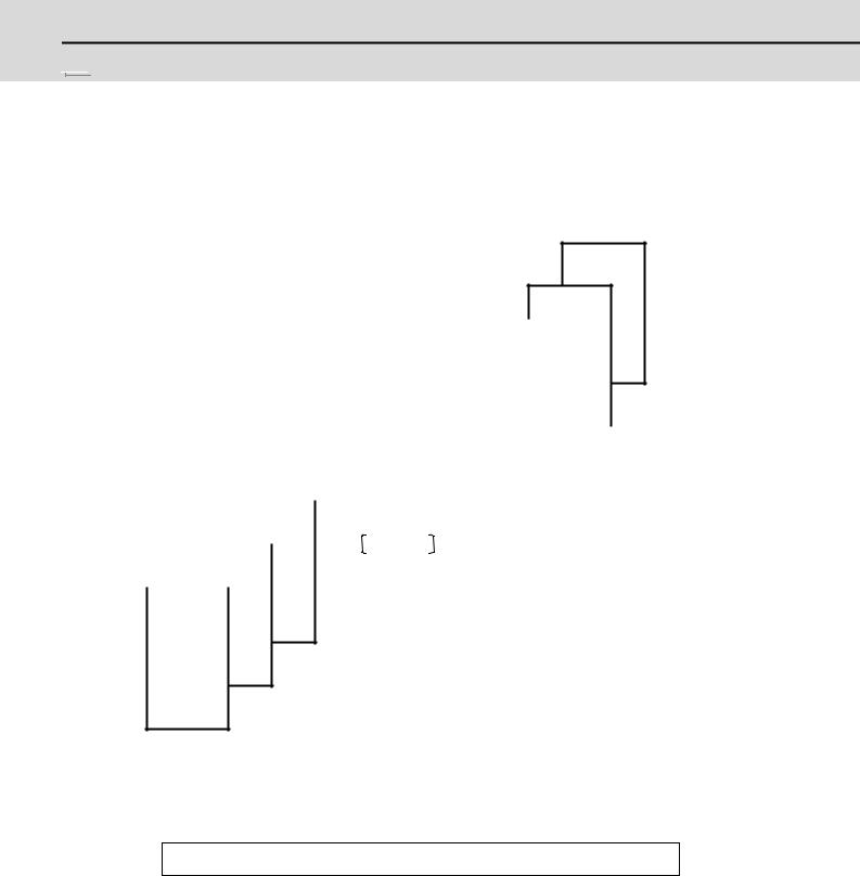
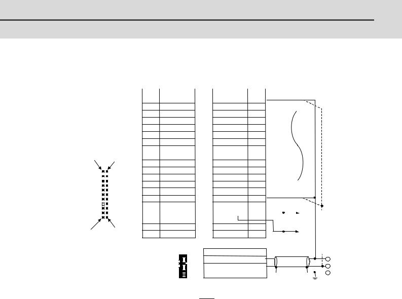
This manual is prepared to assist you to understand the various control signals necessary for creating the sequence program.
The manual is composed as shown below. Refer to related sections as necessary to gain the maximum benefit from the manual.
Handling of M, S, T and B functions
Spindle control
|
|
|
|
|
|
|
|
|
|
|
|
|
|
|
|
|
|
|
|
|
|
|
|
|
|
|
|
|
|
|
|
|
|
|
|
|
|
|
|
|
|
|
|
|
|
|
|
|
|
|
|
|
|
|
|
|
|
|
|
|
|
|
|
|
Explanation |
of |
|
|
|
|
|
|
|
|
|
|
|
|
|
|
interface |
|
|
|
|
|
|||
|
|
|
|
|
|
|
|
|
signals |
|
|
|
|
|
|||
|
|
|
|
|
|
|
|
|
|
|
|
|
|
|
|
|
|
|
|
|
|
|
|
|
|
Explanation |
of |
|
Device |
|
|
|
|
|
|
|
|
|
|
|
|
|
|
devices |
|
|
Input : |
X, R |
|
|
|
|
|
|
|
|
|
|
Table for input/ |
|
|
|
Output : Y, R |
|
|
|
|
||||
|
|
|
|
|
|
|
|
Special relay |
|
|
|
|
|||||
|
|
|
|
|
output |
|
signals |
|
|
|
|
|
|
|
|||
|
|
|
|
|
|
|
|
|
Others |
|
|
|
|
||||
|
|
|
|
|
with controller |
|
|
|
|
|
|
||||||
|
|
|
|
|
|
|
|
|
|
|
|
|
|
|
|||
|
|
|
Table for input/ |
|
|
|
|
|
|
|
|
|
|
|
|
||
|
|
|
|
|
|
|
|
|
|
|
|
|
|||||
|
|
|
output signals |
|
|
|
|
|
|
|
|
|
|
|
|
||
|
|
|
with machine |
|
|
Blank tables |
|
|
|
|
|
|
|
|
|||
|
System |
|
|
|
for user |
|
|
|
|
|
|
|
|
||||
|
|
|
|
|
|
|
|
|
|
|
|
|
|||||
|
configuration |
|
|
|
|
|
|
|
|
|
|
|
|
||||
|
|
|
|
|
|
|
|
|
|
|
|
|
|
|
|
|
|
|
|
|
|
|
|
|
|
|
|
|
|
|
|
|
|
|
|
PLC Interface
Manual
(cover)
<Caution>
Please note that the specifications referred to in the text represents the maximum specifications which include also those under development.
2

2
System Configuration
3
MITSUBISHI CNC

 2 System Configuration
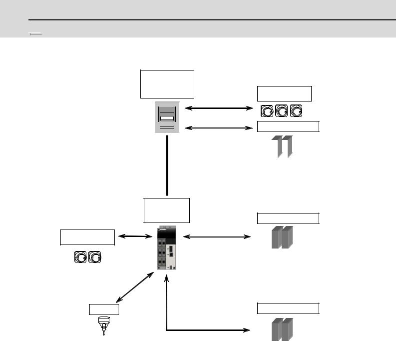
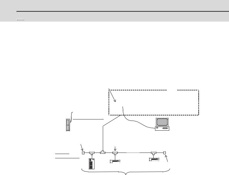
Operation panel
I/O unit
with DIO Manual pulse generator
Expansion DIO card  Input:32 points
 (32 points selected from X200 to X2BF)
  Output:32 points
  (Y200
(Y200
(32 points selected from Y200 to Y2BF) The device No. is determined depending on the rotary switch setting.
Connectors on the operation panel I/O unit Input:32 points
(32 points selected from X200 to X2BF) Output:32 points
(32 points selected from Y200 to Y2BF) The device No. is determined depending on the rotary switch setting.
Manual pulse generator
Sensor
Max.8 channels (X178 to X17F)
RIO3 |
Remote I/O unit |
|
Up to 6 channels can be |
|
|
|
|
(Max.5 units) |
|
|
|
|
||
used with a combination of |
|
|
|
|
|
an operation panel I/O unit |
|
|
|
|
|
and a remote I/O 3ch. |
|
|
|
|
|
DX1** |
|||||
Max.input:160 points
(5 channels selected from X200 to X2BF) Max.output:160 points
(5 channels selected from Y200 to Y2BF) When an expansion DIO card is mounted, 128 points (4 channels) is the max.
Remote I/O unit
RIO1
(Max.8 units)
DX1**
Max.input:256 points (X000 to X0FF)
Max.output:256 points (Y000 to Y0FF)
Remote I/O unit
RIO2
(Max.8 units)
DX1**
Max.input:256 points (X100 to X1FF)
Max.output:256 points (Y100 to Y1FF)
4
M700V/M70V Series PLC Interface Manual
2.1 Relation of RIO Unit and Devices
2.1 Relation of RIO Unit and Devices
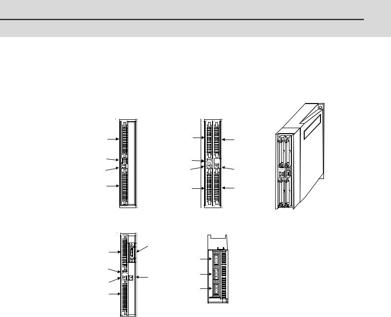
Eight types of remote I/O units (hereafter RIO unit) are available as shown below. The specifications of DX10*, DX11*, DX12* and DX14* (* is "0" or "1") differ. Each unit has a rotary switch for setting the unit No., and for establishing a relation with the device No. (X, Y).
|
Front |
|
Front |
Outline drawing |
||
(3) |
Left input |
(3) |
Left input |
Right input (6) |
||
|
connector |
|
connector |
connector |
||
|
|
|
|
|||
(1) |
DIOspecifi- |
(1) |
DIOspecifi- |
|
|
|
|
cation switch |
|
cation switch |
|
|
|
(2) |
Rotary |
(2) |
Rotary |
Rotary |
(5) |
|
switch |
||||||
|
switch |
|
switch |
|
||
(4) |
Left output |
(4) |
Left output |
Right output(7) |
||
|
connector |
|
connector |
connector |
||
|
DX10* |
|
DX11*/ DX12* |
|
||
|
Front |
|
Bottom |
|
|
|
|
|
(8) Analog input/ |
|
|
||
|
(3) |
output connector |
|
|
||
|
|
(12) |
RIO1 |
|
||
|
|
|
|
|||
|
|
|
(From controller) |
|||
|
|
|
|
|||
(1) |
(11) |
RIO2 |
|
(5) |
|||
|
(Terminating resister or to next RIO uni |
||
(2) |
|
||
(10) |
|
||
(4) |
DCIN |
||
|
(DC24V input) |
||
|
|
DX14*
No. of remote I/O unit input/output points
Unit model |
Compatible machine control signal |
Left |
Right |
Total |
||
DX10* (FCUA-DX10*) |
Digital input signal |
(DI) (Photocoupler insulation) |
32 points |
- |
32 points |
|
Digital output signal |
(DO) (Non-insulated) |
32 points |
- |
32 points |
||
|
||||||
|
|
|
|
|
|
|
DX11* (FCUA-DX11*) |
Digital input signal |
(DI) (Photocoupler insulation) |
32 points |
32 points |
64 points |
|
Digital output signal |
(DO) (Non-insulated) |
32 points |
16 points |
48 points |
||
|
||||||
|
|
|
|
|
|
|
|
Digital input signal |
(DI) (Photocoupler insulation) |
32 points |
32 points |
64 points |
|
DX12* (FCUA-DX12*) |
Digital output signal |
(DO) (Non-insulated) |
32 points |
16 points |
48 points |
|
|
Analog output (AO) |
|
- |
1 point |
1 point |
|
|
|
|
|
|
|
|
|
Digital input signal |
(DI) (Photocoupler insulation) |
32 points |
- |
32 points |
|
DX14* (FCUA-DX14*) |
Digital output signal |
(DO) (Non-insulated) |
32 points |
- |
32 points |
|
Analog input (AI) |
|
- |
4 points |
4 points |
||
|
|
|||||
|
Analog output (AO) |
|
- |
1 point |
1 point |
|
|
|
|
|
|
|
|
(Note) |
The * mark in the table is 0 when the output is a sink type, and is 1 when the output is a source type. The |
|
input is changeable. |
|
Items (1) to (7) are described in the following pages. |
5
MITSUBISHI CNC

 2 System Configuration
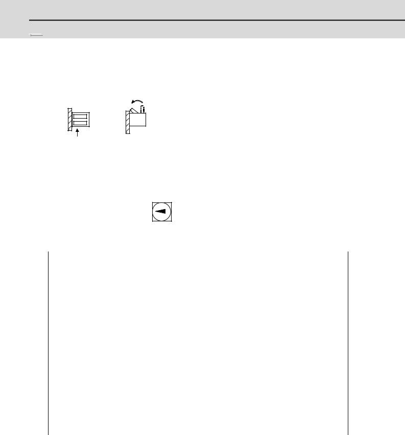
2.1.1 DIO Specification Setting Switch
This switch is not used currently, and must always be set to OFF.
DIO specification setting switch
OFF |
|
(1) |
View from A direction |
Front view |
|
A |
* Use at OFF. |
2.1.2 Rotary Switch for Channel No. Setting
Rotary switch for channel No. setting (2) (5)
Set between 0 and 7.
The device used by the PLC is determined by the setting of the rotary switch for channel No. setting.
Rotary switch No. |
Device No. read in |
Output device No. |
Analog output (AO) |
|
RIO channel 1 |
RIO channel 1 |
RIO channel 1 |
||
|
||||
0 |
X00 to X1F |
Y00 to Y1F(Y0F) |
|
|
|
|
|
|
|
1 |
X20 to X3F |
Y20 to Y3F(Y2F) |
|
|
|
|
|
|
|
2 |
X40 to X5F |
Y40 to Y5F(Y4F) |
The rotary switches |
|
|
|
|
||
3 |
X60 to X7F |
Y60 to Y7F(Y6F) |
correspond to the file |
|
|
|
|
registers R200 to R207 |
|
4 |
X80 to X9F |
Y80 to Y9F(Y8F) |
||
|
|
|
in ascending order. |
|
5 |
XA0 to XBF |
YA0 to YBF(YAF) |
||
|
||||
|
|
|
|
|
6 |
XC0 to XDF |
YC0 to YDF(YCF) |
|
|
|
|
|
|
|
7 |
XE0 to XFF |
YE0 to YFF(YEF) |
|
|
|
|
|
|
Rotary switch No. |
Device No. read in |
Output device No. |
Analog output (AO) |
|
RIO channel 2 |
RIO channel 2 |
RIO channel 2 |
||
|
||||
0 |
X100 to X11F |
Y100 to Y11F(Y10F) |
|
|
|
|
|
|
|
1 |
X120 to X13F |
Y120 to Y13F(Y12F) |
|
|
|
|
|
|
|
2 |
X140 to X15F |
Y140 to Y15F(Y14F) |
The rotary switches |
|
|
|
|
||
3 |
X160 to X17F |
Y160 to Y17F(Y16F) |
correspond to the file |
|
|
|
|
registers R200 to R207 |
|
4 |
X180 to X19F |
Y180 to Y19F(Y18F) |
||
|
|
|
in ascending order. |
|
5 |
X1A0 to X1BF |
Y1A0 to Y1BF(Y1AF) |
||
|
||||
|
|
|
|
|
6 |
X1C0 to X1DF |
Y1C0 to Y1DF(Y1CF) |
|
|
|
|
|
|
|
7 |
X1E0 to X1FF |
Y1E0 to Y1FF(Y1EF) |
|
|
|
|
|
|
6
M700V/M70V Series PLC Interface Manual
2.1 Relation of RIO Unit and Devices
Rotary switch No. |
Device No. read in |
Output device No. |
Analog output (AO) |
|
RIO channel 3 |
RIO channel 3 |
RIO channel 3 |
||
|
||||
0 |
X200 to X21F |
Y200 to Y21F(Y20F) |
|
|
|
|
|
|
|
1 |
X220 to X23F |
Y220 to Y23F(Y22F) |
|
|
|
|
|
|
|
2 |
X240 to X25F |
Y240 to Y25F(Y24F) |
The rotary switches |
|
|
|
|
||
3 |
X260 to X27F |
Y260 to Y27F(Y26F) |
correspond to the file |
|
|
|
|
registers R200 to R205 |
|
4 |
X280 to X29F |
Y280 to Y29F(Y28F) |
||
|
|
|
in ascending order. |
|
5 |
X2A0 to X2BF |
Y2A0 to Y2BF(Y2AF) |
||
|
||||
|
|
|
|
|
6 |
- |
- |
|
|
|
|
|
|
|
7 |
- |
- |
|
|
|
|
|
|
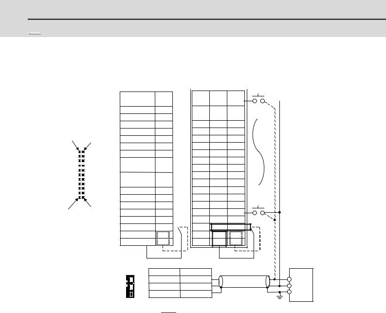
The values shown in parentheses are the device range of the card mounted to the right side of the unit. Only channels available for RIO channel 3 are 0 to 5.
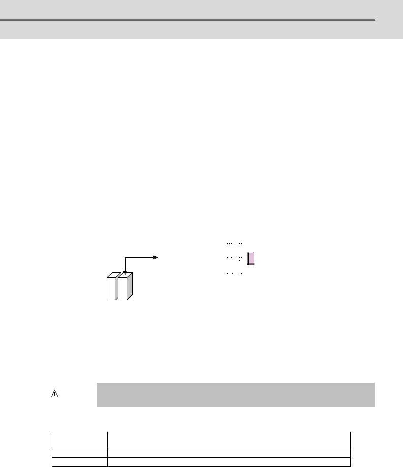
(Note) When the analog output is equipped to several RIO channels, up to four RIO channels will be valid in the following order of priority.
(1) RIO channel 1, (2) RIO channel 2, (3) RIO channel 3
|
(Ex.) |
When the analog output is equipped to RIO channel 1 and RIO channel 3. |
||||||||||||||||||||||
|
|
|
|
|
|
|
|
|
|
|
|
|
|
|
|
|
RIO3 |
|||||||
|
|
|
|
|
|
|
|
|
|
|
|
|
|
|
|
|
|
|
|
|
|
|
|
|
|
|
|
|
|
|
|
|
|
|
|
|
|
|
|
|
|
|
|
|
|
|
|
|
|
|
|
|
|
|
|
|
|
|
|
RIO1 |
|
|
|
|
|
|
|
|
AO |
|
|
|
||
|
|
|
|
|
|
|
|
|
|
|
|
|
|
|
|
|
|
|
|
|
||||
|
|
|
|
|
|
|
|
|
|
Control unit |
|
|
|
|
|
|
|
|
|
|
Sixth station |
|||
|
|
|
|
|
|
|
|
|
|
|
|
|
|
|
|
|
|
|
|
|
||||
|
|
|
|
|
|
|
|
|
|
|
|
|
|
|
|
|
|
|
|
|
|
|
|
|
|
|
|
|
|
|
|
|
|
|
|
|
|
|
|
|
|
|
|
|
|
|
|
|
|
|
|
|
|
AO |
|
AO |
|
|
|
|
|
|
|
|
|
|
|
|
|
|
|
|
||
|
|
|
|
|
RIO unit |
|
|
|
Operation panel I/O unit |
|||||||||||||||
|
|
|
|
|
|
|
|
|
|
|
|
|||||||||||||
|
|
|
|
|
|
|
|
|
|
|
|
|
|
|
|
|
|
|
|
|
|
|
|
|
|
|
|
|
Fourth |
Second |
|
|
|
|
|
|
|
|
|
|
|
|
|
|
|||||
|
|
|
|
station |
station |
|
|
|
|
|
|
|
|
|
|
|
|
|
|
|||||
|
|
|
|
|
|
|
|
|
|
|
|
|
|
|
|
|
|
|
|
|
|
|
|
|
|
|
|
|
#3024 sout |
|
R register |
|
Allocation of AO |
|
|
|
|
||||||||||||
|
|
|
|
2 |
|
|
|
|
|
R200 (AO1) |
|
2nd station of RIO 1 |
|
|
|
|
||||||||
|
|
|
|
|
|
|
|
|
|
|
|
|
|
|
|
|
|
|
|
|
|
|
|
|
|
|
|
|
3 |
|
|
|
|
|
R201 (AO2) |
|
4th station of RIO 1 |
|
|
|
|
||||||||
|
|
|
|
|
|
|
|
|
|
|
|
|
|
|
|
|
|
|
|
|
|
|
|
|
|
|
|
|
4 |
|
|
|
|
|
R202 (AO3) |
|
6th station of RIO 1 |
|
|
|
|
||||||||
|
|
|
|
|
|
|
|
|
|
|
|
|
|
|
|
|
|
|
|
|
|
|
|
|
|
|
|
|
5 |
|
|
|
|
|
R203 (AO4) |
|
- |
|
|
|
|
|
|
|
|
|
|||
|
|
|
|
|
|
|
|
|
|
|
|
|
|
|
|
|
|
|
|
|
|
|
||
|
|
|
|
Since the analog output R registers are allocated in ascending order of channels and station |
||||||||||||||||||||
|
|
|
|
|||||||||||||||||||||
|
CAUTION |
|
||||||||||||||||||||||
|
|
numbers, the analog output destination may change depending on added option. |
||||||||||||||||||||||
|
|
|
|
|||||||||||||||||||||
|
|
|
|
|
|
|
|
|
|
|
|
|
|
|
|
|
|
|
|
|
|
|
|
|
|
No. of points occupied by each unit |
|
|
|
|
|
|
|
|
|
|
|
|
|
|
|||||||||
|
|
|
|
|
|
|
|
|
|
|
|
|
|
|
|
|
|
|
|
|
|
|
||
|
No. of occupied |
|
|
|
|
|
|
|
Unit name |
|||||||||||||||
|
points |
|
|
|
|
|
|
|
|
|
|
|||||||||||||
|
|
|
|
|
|
|
|
|
|
|
|
|
|
|
|
|
|
|
|
|
|
|||
1DX100/DX101, Operation panel I/O unit DX670/DX671
2DX110/DX111, DX120/DX121, DX140/DX141, Operation panel I/O unit DX770/DX771
A max. of 8 units can be connected. DX67* operation panel I/O unit is counted as 1 and DX77* operation panel I/O unit is counted as 2 occupied points. DX11*/DX12*/DX14* remote I/O units are counted as 2, and DX100/DX101 remote I/O units are counted as 1 occupied point.
(Example 1) An operation panel I/O unit (DX771 x1) and remote I/O units (DX120 x3).
(Example 2) An operation panel I/O unit (DX771 x1) and remote I/O units (DX110 x1, DX100 x4).
7
MITSUBISHI CNC

 2 System Configuration
2.1.3Relation of Connector Pins and Device
(1)Input (DI) signal
Set rotary switch to 0
|
(3) |
|
|
|
B |
A |
|
|
|||||
|
|
|
|
|
|||||||||
|
|
|
|
|
|
|
|
|
|
|
|
||
|
|
|
|
|
|
|
|
20 |
|
X00 |
X10 |
|
|
|
|
|
|
|
|
|
|
19 |
|
X01 |
X11 |
|
|
Connector for contact input (DI) |
|
18 |
|
X02 |
X12 |
|
|
||||||
|
17 |
|
X03 |
X13 |
|
|
|||||||
B20 pin |
|
|
|
|
|
A20 pin |
|
16 |
|
X04 |
X14 |
|
|
|
|
|
|
|
|
15 |
|
X05 |
X15 |
|
|
||
|
|
|
|
|
|
|
|
14 |
|
X06 |
X16 |
|
|
|
|
|
|
|
|
|
|
|
|
||||
(3) |
|
|
|
|
|
|
|
13 |
|
X07 |
X17 |
|
|
(6) |
|
|
|
|
|
|
|
12 |
|
X08 |
X18 |
|
|
|
|
|
|
|
|
|
11 |
|
X09 |
X19 |
|
|
|
|
|
|
|
|
|
|
|
|
|
|
|||
|
|
|
|
|
|
|
|
10 |
|
X0A |
X1A |
|
|
|
|
|
|
|
|
|
|
9 |
|
X0B |
X1B |
|
|
|
|
|
|
|
|
|
|
8 |
|
X0C |
X1C |
|
|
|
|
|
|
|
|
|
|
7 |
|
X0D |
X1D |
|
|
B01 pin |
|
|
|
|
|
A01 pin |
|
6 |
|
X0E |
X1E |
|
|
|
|
|
|
|
|
|
|
||||||
|
|
|
|
|
|
5 |
|
X0F |
X1F |
|
|
||
|
|
|
|
|
|
|
|||||||
|
|
|
|
|
|
|
|
4 |
|
|
|
|
|
|
|
|
|
|
|
|
|
3 |
|
COM |
COM |
|
|
|
|
|
|
|
|
|
|
2 |
|
|
0V |
|
|
|
|
|
|
|
|
|
|
|
+24V |
|
|
||
|
|
|
|
|
|
|
|
1 |
|
+24V |
0V |
|
|
|
|
|
|
|
|
|
|
|
|
|
|
|
|
( 10) |
|
|
|
|
|
1 |
1 |
|
|
|
|
|
|||
|
|
|
|
|
|
2 |
2 |
|
|
|
|
|
|
||
|
|
|
|
|
|
3 |
3 |
|
|
|
|
|
|
||
|
|
|
|
|
|
||
|
|
|
|
|
|
|
|
Set rotary switch to 1
(6) |
|
|
|
|
|
X00 |
|
|
|
B |
|
|
|||
|
|
|
A |
|
|||
20 |
X20 |
X30 |
|
||||
|
|||||||
|
19 |
X21 |
X31 |
|
|||
18 |
X22 |
X32 |
|||||
17 |
X23 |
X33 |
|||||
16 |
X24 |
X34 |
|||||
15 |
X25 |
X35 |
|||||
14 |
X26 |
X36 |
|||||
13 |
X27 |
X37 |
|||||
12 |
X28 |
X38 |
|||||
11 |
X29 |
X39 |
|||||
10 |
X2A |
X3A |
|||||
9 |
X2B |
X3B |
|||||
8 |
X2C |
X3C |
|||||
7 |
X2D |
X3D |
6 |
X2E |
X3F |
X3E |
||
5 |
X2F |
X3F |
4 |
|
|
3 |
COM |
COM |
2 |
+24V |
0V |
1 |
+24V |
0V |
|
|
Stabilized |
|
|
power supply |
Signal |
|
|
DC+24V IN |
|
+24V |
0V |
|
0V |
FG |
|
FG |
|
|
Connection for contact common=GND (sink type)

 Connection for contact common=DC+24V (source type)
(Note 1) The No. of points (devices) will differ according to the RIO unit type.
(Note 2) The devices shown here show an example for when the rotary switch for channel No. setting on the RIO unit is set to "0" and set to "1".
Refer to the section "Rotary Switch for Channel No. Setting" for details on the relation of the rotary switch and device No.
8
M700V/M70V Series PLC Interface Manual
2.1 Relation of RIO Unit and Devices
(2)Output (DO) signal
|
|
|
|
|
Set rotary switch to 0 |
|
|
|
Set rotary switch to 1 |
|
|
|
|
|
|
|
|
|
|
|
|
|
|
|
|
|
||||||||||||||||||
|
(4) |
|
|
|
|
|
|
|
|
|
|
|
|
(7) |
|
|
|
|
|
|
|
|
|
|
|
|
|
|
|
Y00 |
|
|
|
|
||||||||||
|
|
|
B |
|
A |
|
|
|
|
|
B |
|
A |
|
|
|
|
|
|
|
|
|
|
|||||||||||||||||||||
|
|
|
|
|
|
|
|
|
|
|
|
|
|
|
|
|
|
|
|
|
|
|
|
|||||||||||||||||||||
|
|
|
|
|
20 |
Y00 |
|
Y10 |
|
|
20 |
|
Y20 |
|
|
|
|
|
|
|
|
|
|
L |
|
|
|
|
|
|
|
|
||||||||||||
|
|
|
|
|
19 |
Y01 |
|
Y11 |
|
|
19 |
|
Y21 |
|
|
|
|
|
|
|
|
|
|
|
|
|
|
|
|
|
|
|
|
|
||||||||||
|
|
|
|
|
18 |
Y02 |
|
Y12 |
|
|
18 |
|
Y22 |
|
|
|
|
|
|
|
|
|
|
|
|
|
|
|
|
|
|
|
|
|
||||||||||
|
|
|
|
|
17 |
Y03 |
|
Y13 |
|
|
17 |
|
Y23 |
|
|
|
|
|
|
|
|
|
|
|
|
|
|
|
|
|
|
|
|
|
||||||||||
|
|
|
|
|
16 |
Y04 |
|
Y14 |
|
|
16 |
|
Y24 |
|
|
|
|
|
|
|
|
|
|
|
|
|
|
|
|
|
|
|
|
|
||||||||||
|
|
|
|
|
15 |
Y05 |
|
Y15 |
|
|
15 |
|
Y25 |
|
|
|
|
|
|
|
|
|
|
|
|
|
|
|
|
|
|
|
|
|
||||||||||
Connector for contact output (DO) |
14 |
Y06 |
|
Y16 |
|
|
14 |
|
Y26 |
|
|
|
|
|
|
|
|
|
|
|
|
|
|
|
|
|
|
|
|
|
||||||||||||||
|
13 |
Y07 |
|
Y17 |
|
|
|
|
13 |
|
Y27 |
|
|
|
|
|
|
|
|
|
|
|
|
|
|
|
|
|
|
|
|
|
||||||||||||
B20 pin |
|
|
|
A20 pin |
|
|
|
|
|
|
|
|
|
|
|
|
|
|
|
|
|
|
|
|
|
|
|
|
|
|||||||||||||||
|
|
|
12 |
Y08 |
|
Y18 |
|
|
12 |
|
Y28 |
|
|
|
|
|
|
|
|
|
|
|
|
|
|
|
|
|
|
|
|
|
||||||||||||
|
|
|
|
|
|
|
|
|
|
|
|
|
|
|
|
|
|
|
|
|
|
|
|
|
|
|
|
|
|
|||||||||||||||
|
|
|
|
|
11 |
Y09 |
|
Y19 |
|
|
11 |
|
Y29 |
|
|
|
|
|
|
|
|
|
|
|
|
|
|
|
|
|
|
|
|
|
||||||||||
(4) |
|
|
|
|
10 |
Y0A |
|
Y1A |
|
|
10 |
|
Y2A |
|
|
|
|
|
|
|
|
|
|
|
|
|
|
|
|
|
|
|
|
|
||||||||||
|
|
|
|
|
|
|
|
|
|
|
|
|
|
|
|
|
|
|
|
|
|
|
|
|
||||||||||||||||||||
|
|
|
|
9 |
Y0B |
|
Y1B |
|
|
9 |
|
Y2B |
|
|
|
|
|
|
|
|
|
|
|
|
|
|
|
|
|
|
|
|
|
|||||||||||
(7) |
|
|
|
|
|
|
|
|
|
|
|
|
|
|
|
|
|
|
|
|
|
|
|
|
|
|
|
|
|
|||||||||||||||
|
|
|
|
8 |
Y0C |
|
Y1C |
|
|
8 |
|
Y2C |
|
|
|
|
|
|
|
|
|
|
Y2F |
|
|
|
||||||||||||||||||
|
|
|
|
|
7 |
Y0D |
|
Y1D |
|
|
7 |
|
Y2D |
|
|
|
|
|
|
|
|
|
|
|
|
|
||||||||||||||||||
|
|
|
|
|
6 |
Y0E |
|
Y1E |
|
|
6 |
|
Y2E |
|
|
|
|
|
|
|
|
|
|
L |
|
|
|
|
|
|
|
|
|
|||||||||||
|
|
|
|
|
|
5 |
Y0F |
|
Y1F |
|
|
|
|
5 |
|
Y2F |
|
|
|
|
|
|
|
|
|
|
|
|
|
|
|
|
|
|
|
|
|
|||||||
|
|
|
|
|
|
|
|
|
|
|
|
|
|
|
|
|
|
|
|
|
|
|
|
|
|
|||||||||||||||||||
|
|
|
|
|
|
4 |
|
|
|
|
|
|
|
|
|
|
|
|
|
4 |
|
|
AO |
|
AO* |
|
|
|
|
|
|
|
|
|
|
|
|
|
|
|
|
|
|
|
|
|
|
|
|
3 |
|
|
|
|
|
|
|
|
|
|
|
|
3 |
|
+24V |
|
|
|
|
|
|
|
|
|
|
|
|
|
|
|
|
|
|
|
|
|
|||
|
|
|
|
|
|
|
|
|
|
|
|
|
|
|
|
|
|
|
|
|
|
|
|
|
|
|
|
|
|
|
|
|
|
|
|
|
||||||||
B01 pin |
|
|
|
A01 pin |
2 |
+24V |
|
0V |
|
|
2 |
|
|
0V |
|
|
|
|
|
|
|
|
|
|
|
|
|
|
|
|
|
|||||||||||||
|
|
|
1 |
+24V |
|
0V |
|
|
1 |
|
+24V |
|
0V |
Analog output |
Stabilized |
|||||||||||||||||||||||||||||
|
|
|
|
|
|
|
|
|
|
|||||||||||||||||||||||||||||||||||
|
|
|
|
|
|
|
|
|
|
|
|
|
|
|
|
|
|
|
|
|
|
|
|
|
|
|
|
power supply |
||||||||||||||||
|
|
|
|
|
|
|
|
|
|
|
|
|
|
|
|
|
|
|
|
|
|
|
|
|
|
|
|
|||||||||||||||||
|
|
|
|
|
|
|
|
|
|
|
|
|
|
|
|
|
|
|
|
|
|
|
|
|
|
|
|
(For DX120/1 only) |
|
|
|
|||||||||||||
|
|
|
|
|
|
|
|
|
|
|
|
|
|
|
|
|
|
|
|
|
|
|
|
|
|
|
|
|
|
|
||||||||||||||
|
|
|
|
|
|
|
( 10) |
|
|
|
|
|
|
|
1 |
|
1 |
|
|
Signal |
|
|
|
|
|
|
|
|
|
|
|
|
|
|
|
+24V |
|
|||||||
|
|
|
|
|
|
|
|
|
|
|
|
|
|
|
|
|
DC+24V IN |
|
|
|
|
|
|
|
|
|
|
|
|
|
|
|
|
|||||||||||
|
|
|
|
|
|
|
|
|
|
|
|
|
|
|
2 |
|
2 |
|
|
|
0V |
|
|
|
|
|
|
|
|
|
|
|
|
|
|
|
0V |
|
||||||
|
|
|
|
|
|
|
|
|
|
|
|
|
|
|
|
|
|
|
|
|
|
|
|
|
|
|
|
|
|
|
|
|
|
FG |
|
|||||||||
|
|
|
|
|
|
|
|
|
|
|
|
|
|
|
3 |
|
3 |
|
|
|
FG |
|
|
|
|
|
|
|
|
|
|
|
|
|
|
|
|
|
||||||
|
|
|
|
|
|
|
|
|
|
|
|
|
|
|
|
|
|
|
|
|
|
|
|
|
|
|
|
|
|
|
|
|
|
|
|
|
||||||||
|
|
|
|
|
|
|
|
|
|
|
|
|
|
|
|
|
|
|
|
|
|
|
|
|
|
|
|
|
|
|
|
|
|
|
|
|
|
|
|
|
|
|
|
|
Connection for contact common=GND (sink type)

 Connection for contact common=DC+24V (source type)
(Note 1) The No. of points (devices) will differ according to the RIO unit type.
(Note 2) The devices shown here show an example for when the rotary switch for channel No. setting on the RIO unit is set to "0" and set to "1".
Refer to the section "Rotary Switch for Channel No. Setting" for details on the relation of the rotary switch and device No.
(Note 3) The A4 and B4 pin analog output (AO, AO*) in the output connector (7) is found only on the RIO unit DX120/ DX121.
Refer to the section "Outline of Analog Signal Input Circuit " for details on DX140/DX141 connector.
9
MITSUBISHI CNC

 2 System Configuration
2.2 Outline of Digital Signal Input Circuit
Both 24V common and 0V common connections are allowed in the digital signal input circuit. Follow the wiring diagram below for each type.
Input circuit
24V common |
|
|
0V common |
|
||
|
DI-L / DI-R |
|
|
|
DI-L / DI-R |
|
|
(Machine side) |
|
|
|
(Machine side) |
|
External contact |
Input resistor |
|
External contact |
Input resistor |
||
R 2.2k |
|
R 2.2k |
||||
|
Input voltage |
|
|
|
Input voltage |
|
Stabilized |
|
|
Control |
Stabilized |
|
|
|
|
circuit |
|
|
||
power supply |
|
|
|
power supply |
|
|
24VDC(+) |
|
COM |
|
24VDC(+) |
|
COM |
0V |
|
|
0V |
|
||
A3,B3 |
|
|
A3,B3 |
|
||
FG |
|
|
FG |
|
||
|
|
|
|
|
||
Control
circuit
Input conditions
The input signals must be used within the following condition ranges.
|
|
|
24V common |
|
0V common |
|
1 |
Input voltage at external contact ON |
6V or less |
|
18V or more, 25.2V or less |
|
|
|
|
|
|
|
||
2 |
Input current at external contact ON |
9mA or more |
|
|||
3 |
Input voltage at external contact OFF |
20V or more, 25.2V or less |
|
4V or less |
|
|
|
|
|
|
|
||
4 |
Input current at external contact OFF |
2mA or less |
|
|||
|
|
|
|
|||
5 |
Input resistance |
Approx. 2.2kΩ |
|
|||
|
|
|
|
|
||
6 |
Tolerable chattering time (T1) |
|
3ms |
|
||
|
|
|
|
|||
7 |
Input signal holding time (T2) |
40ms or more (Note) |
|
|||
|
|
|
|
|
|
|
8 |
input circuit operation delay time (T3 |
3ms T3 T4 16ms |
|
|||
and T4) |
|
|||||
9 |
Machine side contact capacity |
30V or more, 16mA or more |
|
|||
|
|
|
|
|
|
|
(Note) |
Input signal holding time: The guide is 40ms or more. The input signal will not be recognized unless |
|||||
|
|
it is held for the ladder processing cycle time or longer. |
|
|
|
|
Connection to 24V common input |
|
Connection to 0V common input |
|
||
|
T2 |
|
|
T2 |
|
(E) |
T1 |
T1 |
(E) |
T1 |
T1 |
|
|
||||
+24V |
|
|
+24V |
|
|
GND |
|
|
GND |
|
|
(I) |
|
|
(I) |
|
|
|
T3 |
T4 |
|
T3 |
T4 |
(E) : External signal, (I):Internal signal
10
M700V/M70V Series PLC Interface Manual
2.3 Outline of Digital Signal Output Circuit
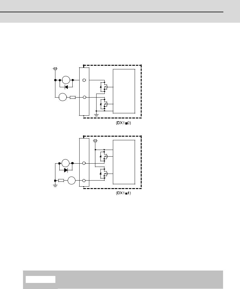
2.3 Outline of Digital Signal Output Circuit
The digital signal output circuit uses a sink type (DX1*0) or source type (DX1*1). Use within the specification ranges shown below.
Output circuit
(Machine side) |
DO-L/DO-R |
|
24VDC(+) |
|
|
RA |
|
|
R |
Control |
|
circuit |
||
PL |
|
|
|
Sink type |
|
|
DO-L/DO-R |
|
(Machine side) |
24VDC(+) |
|
|
||
RA |
Control |
|
circuit |
||
|
||
R |
|
|
PL |
|
Source type
Output conditions
Insulation method |
Non-insulation |
Rated load voltage |
24VDC |
|
|
Max. output current |
60mA/point |
|
|
Output delay time |
40μs |
|
|
(Note 1) When using an inductive load such as a relay, always connect a diode (voltage resistance 100V or more, 100mA or more) in parallel to the load.
(Note 2) When using a capacitive load such as a lamp, always connect a protective resistor (R=150Ω) serially to the load to suppress rush currents. (Make sure that the current is less than the above tolerable current including the momentary current.)
1. When using an inductive load such as a relay, always connect a diode in parallel to the load.  CAUTION 2. When using a capacitive load such as a lamp, always connect a protective resistor serially
to the load to suppress rush currents.
11
MITSUBISHI CNC

 2 System Configuration
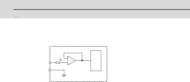
2.4 Outline of Analog Signal Input Circuit
The analog signal input circuit can be used only for FCUA-DX140/DX141.
Input circuit
150 |
ADC |
|
AI |
||
|
||
AI* |
|
|
|
OV(RG) |
|
Input conditions |
|
Max. input rating |
± 15V |
|
|
Resolution |
10V/2000 (5mV) |
|
|
Precision |
Within ± 25mV |
|
|
AD input sampling time |
14.2ms(AI0)/ 42.6ms(AI1 to 3) |
|
|
12
M700V/M70V Series PLC Interface Manual
2.5 Outline of Analog Signal Output Circuit
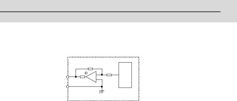
2.5 Outline of Analog Signal Output Circuit
The analog signal output circuit can be used only for FCUA-DX120/DX121/DX140/DX141.
Output circuit
|
R |
220 |
R |
A0 |
DAC |
|
|
A0* |
|
|
OV(RG) |
Output conditions
Output voltage |
0V to ± 10V ( ± 5%) |
|
|
Resolution |
12bit ( ± 10V × n/4096) (Note) |
|
|
Load conditions |
10kΩ load resistance |
|
|
Output impedance |
220Ω |
|
|
(Note) n=(20 to 211)
13
MITSUBISHI CNC

 2 System Configuration
2.6 Outline of I/O Assignment with PROFIBUS-DP
By installing PROFIBUS-DP unit (FCU7-HN571) on an arbitrary section of CNC expansion slot, slave stations compatible with PROFIBUS-DP communication can be connected to input/output device. No option parameter setting is needed.
Hilsher's Fieldbus communication control unit (COM module) is mounted on HN571, and NC operates as the master station. Up to 128 units can be connected with master station and slave stations combined.
Inputs/outputs of the devices from NC's PLC are all handled as bit device data. Up to 512 points can be input/output. Maximum number of inputs/outputs for NC remote I/O unit is 768, whether or not HN571 is installed.
|
HN571 unit for |
|
|
|
|
|
|
|
|
|||||||
|
master station communication |
|
(option) |
|||||||||||||
|
|
|
|
|
|
|
|
|
|
|
|
|
|
|
|
|
CNC control unit |
|
|
|
|
|
|
|
|
|
|
|
|
|
|
|
|
|
|
|
|
Expantion Unit FCU7 - EX89* |
|
|
||||||||||
CNC UNIT |
|
|
|
|
|
|
|
|
|
|
|
|
|
|
|
|
|
|
|
|
|
|
Slot1 |
|
Slot2 |
|
Slot3 |
|
|
|
|
||
|
|
|
|
|
|
|
|
|
|
|
FieldBus OPT2 etc |
|||||
FCU7 - MU001/MU011 |
|
|
|
|
|
|
|
|
|
|
|
|||||
|
|
|
|
|
|
|
|
|
|
|
|
|
|
|
|
|
|
|
|
|
|
|
|
|
|
|
|
|
|
|
|
|
|
|
|
|
|
|
|
|
|
|
|
|
|
|
|
|
|
|
|
|
|
|
|
|
|
|
|
|
|
|
|
|
|
|
|
|
|
|
|
|
|
|
|
|
|
|
|
|
|
|
|
|
RIO communication
RS - 232C
Windows PC for parameter settings
+
Hilsher configurator
Terminator
Tap
Fieldbus
communication
Terminator
Master + slave: 128 units
Fieldbus connection outline
Machine input/output signal allocation
Input/output device allocation when HN571 is mounted is as shown below.
|
|
RIO communication only |
|
With PROFIBUS-DP communication |
|
||||
|
|
RIO1 |
RIO2 |
RIO3 |
RIO1 |
RIO2 |
RIO3 |
PROFIBUS-DP |
|
|
|
communication |
|
||||||
|
|
|
|
|
|
|
|
|
|
|
Input |
X00 to XFF |
X100 to |
X200 to |
X00 to XFF |
X100 to |
X200 to |
X400 to X5FF |
|
|
X1FF |
X2FF |
X1FF |
X2FF |
|
||||
|
|
|
|
|
|
||||
|
|
|
|
|
|
|
|
|
|
|
Output |
Y00 to YFF |
Y100 to |
Y200 to |
Y00 to YFF |
Y100 to |
Y200 to |
Y400 to Y5FF |
|
|
Y1FF |
Y2FF |
Y1FF |
Y2FF |
|
||||
|
|
|
|
|
|
||||
|
|
|
|
|
|
|
|
|
|
(Note) |
OT/DOG arbitrary allocation cannot be made for the device compatible with PROFIBUS-DP communication. |
||||||||
14

M700V/M70V Series PLC Interface Manual
2.7 Fixed Signals
2.7 Fixed Signals
The connector pin Nos. in the input signals that are fixed are shown below.
Note that using the methods below can ignore fixed signals and change the allocations.
|
Signal name |
Device |
Signal name |
Device |
|
Emergency stop |
EMG of main unit |
Stroke end -1 |
X20 |
|
|
|
|
|
|
|
|
Stroke end +1 |
X28 |
Stroke end -2 |
X21 |
|
|
|
|
|
|
|
|
Stroke end +2 |
X29 |
Stroke end -3 |
X22 |
|
|
|
|
|
|
|
|
Stroke end +3 |
X2A |
Stroke end -4 |
X23 |
|
|
|
|
|
|
|
|
Stroke end +4 |
X2B |
Stroke end -5 |
X64 |
|
|
|
|
|
|
|
|
Stroke end +5 |
X6C |
Stroke end -6 |
X65 |
|
|
|
|
|
|
|
|
Stroke end +6 |
X6D |
Stroke end -7 |
X66 |
|
|
|
|
|
|
|
|
Stroke end +7 |
X6E |
Stroke end -8 |
X67 |
|
|
|
|
|
|
|
|
Stroke end +8 |
X6F |
|
|
|
|
|
|
|
|
|
|
Reference position return near-point |
X18 |
|
|
|
|
detection 1 |
|
|
|
|
|
|
|
|
|
|
|
|
|
|
|
|
|
Reference position return near-point |
X19 |
|
|
|
|
detection 2 |
|
|
|
|
|
|
|
|
|
|
|
|
|
|
|
|
|
Reference position return near-point |
X1A |
|
|
|
|
detection 3 |
|
|
|
|
|
|
|
|
|
|
|
|
|
|
|
|
|
Reference position return near-point |
X1B |
|
|
|
|
detection 4 |
|
|
|
|
|
|
|
|
|
|
|
|
|
|
|
|
|
Reference position return near-point |
X5C |
|
|
|
|
detection 5 |
|
|
|
|
|
|
|
|
|
|
|
|
|
|
|
|
|
Reference position return near-point |
X5D |
|
|
|
|
detection 6 |
|
|
|
|
|
|
|
|
|
|
|
|
|
|
|
|
|
Reference position return near-point |
X5E |
|
|
|
|
detection 7 |
|
|
|
|
|
|
|
|
|
|
|
|
|
|
|
|
|
Reference position return near-point |
X5F |
|
|
|
|
detection 8 |
|
|
|
|
|
|
|
|
|
|
|
|
|
|
|
|
|
(Note) |
When using the multi-part system and the 1st part system has 2 axes and the 2nd part system has 1 axis, the |
||||
|
1st axis in the 2nd part system will correspond to the 3rd axis above. |
|
|
||
2.7.1 Ignoring Fixed Signals
The fixed signals can be used as other signals by ignoring them with file registers R248 and R272.
15

MITSUBISHI CNC

 2 System Configuration
2.7.2 Changing the Addresses of Fixed Signals
The fixed devices can be allocated arbitrarily with the following parameters.
The parameters #2073 to #2075 are valid when 1 is set in #1226 aux10 bit 5.
When the parameters #2073 to #2075 are valid, do not set the same device number. If the same device number exists, an emergency stop occurs. However, no device number check is performed for an axis to which a signal (R248, R272) that ignores the fixed signal is input.
When the arbitrary allocation is valid, the fixed signals can be used as other signals.
# |
|
Items |
Details |
Setting range |
|
|
(unit) |
||||
|
|
|
|
|
|
|
|
|
Arbitrary |
Specify whether to enable the arbitrary allocation parameter for the |
|
|
aux10 |
|
origin dog and H/W OT. |
|
|
1226 |
|
allocation of |
0/1 |
||
(bit5) |
|
0: Disable arbitrary allocation. (Fixed device) |
|||
|
|
dog signal |
|
||
|
|
|
1: Enable arbitrary allocation. (Device specified by the parameter) |
|
|
|
|
|
|
|
|
|
|
|
|
|
|
|
|
|
|
Under the standard specifications, the origin dog signal is assigned |
|
|
|
|
|
to a fixed device. When it is desired to assign the origin dog signal |
|
|
|
|
|
to a position other than the fixed device, specify the input device in |
|
|
|
|
|
this parameter. |
|
2073 |
zrn_dog |
|
Origin dog |
This parameter is enabled in the following conditions. |
0000 to 02FF |
|
NC axis: When "#1226 aux10/bit5" is set to "1". |
||||
|
(HEX) |
||||
|
|
|
|
PLC axis: When "#1246 set18/bit7" is set to "1". |
|
|
|
|
|
|
|
|
|
|
|
- When this parameter is valid, do not set the same device number. |
|
|
|
|
|
If the same device number exists, an emergency stop occurs. |
|
|
|
|
|
However, no device number check is performed for an axis to which |
|
|
|
|
|
a signal that ignores the near-point dog signal (R272) is input. |
|
|
|
|
|
|
|
|
|
|
|
Under the standard specifications, the OT (+) signal is assigned to |
|
|
|
|
|
a fixed device. When it is desired to assign the OT (+) signal to a |
|
|
|
|
|
position other than the fixed device, specify the input device in this |
|
|
|
|
|
parameter. |
|
2074 |
H/W_OT+ |
|
H/W OT+ |
This parameter is enabled in the following conditions. |
0000 to 02FF |
|
NC axis: When "#1226 aux10/bit5" is set to "1". |
||||
|
(HEX) |
||||
|
|
|
|
PLC axis: When "#1246 set18/bit7" is set to "1". |
|
|
|
|
|
|
|
|
|
|
|
- When this parameter is valid, do not set the same device number. |
|
|
|
|
|
If the same device number exists, an emergency stop occurs. |
|
|
|
|
|
However, no device number check is performed for an axis to which |
|
|
|
|
|
a signal that ignores the OT signal (R248) is input. |
|
|
|
|
|
|
|
|
|
|
|
Under the standard specifications, the OT (-) signal is assigned to |
|
|
|
|
|
a fixed device. When it is desired to assign the OT (-) signal to a |
|
|
|
|
|
position other than the fixed device, specify the input device in this |
|
|
|
|
|
parameter. |
|
2075 |
H/W_OT- |
|
H/W OT- |
This parameter is enabled in the following conditions. |
0000 to 02FF |
|
NC axis: When "#1226 aux10/bit5" is set to "1". |
||||
|
(HEX) |
||||
|
|
|
|
PLC axis: When "#1246 set18/bit7" is set to "1". |
|
|
|
|
|
|
|
|
|
|
|
- When this parameter is valid, do not set the same device number. |
|
|
|
|
|
If the same device number exists, an emergency stop occurs. |
|
|
|
|
|
However, no device number check is performed for an axis to which |
|
|
|
|
|
a signal that ignores the OT signal (R248) is input. |
|
|
|
|
|
|
|
16
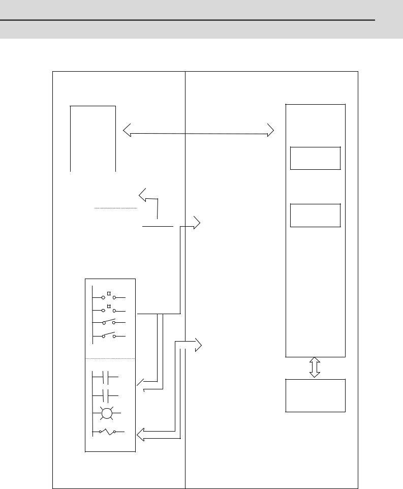
M700V/M70V Series PLC Interface Manual
2.8 Flow of Signals
2.8 Flow of Signals
|
|
PLC |
Controller |
||
|
|
|
Signal in
controller 
 PLCwindow
|
|
|
|
|
|
|
|
|
|
|
|
|
|
|
|
|
|
|
|
|
|
|
|
Signal in |
|
|
|
|
|
|
|
|
|
|
|
||||||
|
|
|
controller |
|
|
|
|
|
|
|
|
|
|
Input/output signal with |
||||||
|
|
|
|
|
|
|
|
|
|
|
|
|
||||||||
|
|
|
Input |
|
|
Y** |
|
|
|
|
|
|||||||||
|
|
|
|
|
|
|
|
|
|
controller and machine |
||||||||||
|
|
|
|
|
|
|
|
|
|
|
|
|
|
|
|
|
|
|
|
|
|
|
|
|
|
|
|
|
|
|
|
|
|
|
|
|
|
|
|
|
(X, Y) |
|
|
|
Output |
|
|
|
|
|
|
|
|
|
|
|||||||
|
|
|
|
|
|
|
|
|
|
|
|
|
|
|||||||
|
|
|
|
X** |
|
|
|
|
|
|
||||||||||
|
|
|
|
|
|
|
|
|
|
|
|
|
|
|
|
|
|
|
|
|
|
|
|
|
|
|
|
|
|
|
|
|
|
|
|
|
|
|
|
|
Transfer at head of |
|
|
|
|
|
|
|
|
|
|
|
|
|
|
|
|
|
|
|
|
main program |
|
|
|
|
|
|
|
|
|
|
|
|
|
|
|
|
|
||||
|
|
|
|
|
|
|
|
|
|
|
|
|
|
|
|
|
|
|
|
|
|
|
|
|
|
|
|
|
|
|
|
|
|
|
|
|
|
|
|
|
|
|
Machine/machine operation board |
|
|
|
|
|
|
|
|
|||||||||||
|
|
|
|
|
|
|
|
|
|
|
|
|
|
|
|
|
|
|
|
|
|
|
|
|
|
|
|
|
|
|
|
|
|
|
|
|
|
|
|
|
|
|
|
|
|
|
|
|
|
|
|
|
|
|
|
|
|
|
|
|
|
|
X**
|
|
|
|
Input/output signal |
|
|
|
|
with machine |
|
|
|
|
(X, Y) |
|
X** |
|
||
|
|
|
||
|
|
|
|
|
Transfer at head of high processing program
 (per 3.5ms)
  Y**
Y**
Sequence program
High-speed
program
(per 3.5ms)
Main program
(Scan time with program size)
Internal relay, latch relay, etc. (M, F, L, · · · )
Y**
17

MITSUBISHI CNC

 2 System Configuration
2.9 List of Devices Used
The devices used by the PLC are shown below.
Device |
Device No. |
Unit |
Details |
Format |
||||
|
|
|
|
|
|
|||
X* |
X0 to X1FFF |
(8192 points) |
1 bit |
Input signal to PLC: Machine input, etc. |
|
|||
|
|
|
|
|
|
|||
Y* |
Y0 to Y1FFF |
(8192 points) |
1 bit |
Output signal from PLC: Machine output, etc. |
|
|||
|
|
|
|
|
||||
M |
M0 to M10239 (10240 points) |
1 bit |
Temporary memory |
1 |
||||
|
|
|
|
|
|
|
|
|
F |
F0 to F1023 |
(1024 points) |
1 bit |
Temporary memory. |
2 |
|||
Alarm message interface |
||||||||
|
|
|
|
|
|
|
||
|
|
|
|
|
|
|||
L |
L0 to L511 |
(512 points) |
1 bit |
Latch relay (back up memory) |
3 |
|||
|
|
|
|
|
|
|||
SM |
SM0 to SM127 |
(128 points) |
1 bit |
Special relay |
|
|||
|
|
|
|
|
||||
SB |
SB0000 to SB01FF |
1 bit |
Special relay |
|
||||
|
|
|
|
|
||||
SW |
SW0000 to SW01FF |
1 bit |
Special register |
|
||||
|
|
|
|
|
|
|
|
|
|
|
|
|
|
|
Timer |
|
|
T |
T0 to T703 |
(704 points) |
1 bit/16 bit |
(The variable/fixed boundary is set with a parameter.) |
4,5 |
|||
|
|
|
|
|
|
(Note 3) |
|
|
|
|
|
|
|
|
|||
ST |
ST0 to ST63 |
(64 points) |
1 bit/16 bit |
Integrated timer (100ms unit) |
6,7 |
|||
|
|
|
|
|
|
|
|
|
C |
C0 to C255 |
(256 points) |
1 bit/16 bit |
Counter (The variable/fixed boundary is set with a |
8,9 |
|||
parameter.) (Note 3) |
||||||||
|
|
|
|
|
|
|
||
|
|
|
|
|
|
|||
D |
D0 to D2047 |
(2048 points) |
16 bit/32 bit |
Data register. Register for calculation |
10 |
|||
|
|
|
|
|
||||
R* |
R0 to R32767 (32768 points) |
16 bit/32 bit |
File register. CNC word interface |
11 |
||||
|
|
|
|
|
|
|||
Z |
Z0 to Z1 |
(2 points) |
16 bit |
Address index |
|
|||
|
|
|
|
|
|
|||
N |
N0 to N7 |
(8 points) |
- |
Master controller nesting level |
|
|||
|
|
|
|
|
|
|
|
|
P* |
P0 to P249 |
|
|
(256 points) |
- |
Label for conditional jump, subroutine call command |
|
|
P4000 to P4005 |
|
|
||||||
|
|
|
|
|
|
|||
|
K-32768 to K32767 |
|
- |
Decimal constant for 16-bit command |
|
|||
K |
|
|
|
|
|
|
||
K-2147483648 |
|
|
- |
Decimal constant for 32-bit command |
|
|||
|
to K2147483647 |
|
||||||
|
|
|
|
|||||
|
|
|
|
|
|
|
|
|
H |
H0 to HFFFF |
|
|
|
- |
Hexadecimal constant for 16-bit command |
|
|
|
|
|
|
|
|
|
||
H0 to HFFFFFFFF |
- |
Hexadecimal constant for 32-bit command |
|
|||||
|
|
|||||||
|
|
|
|
|
|
|
|
|
(Note 1) Devices marked with * in the device column have designated applications. Do not use devices other than those corresponding to the input/output signals with the machine side (input/output signals of the remote I/O unit), even if it is an undefined vacant device.
(Note 2) The format displayed in the table is attached. Copy and use as required. (Note 3) Distinction of 10ms timer and 100ms timer is performed by command.
(10ms timer is performed by OUTH command, 100ms timer is performed by OUT command.)
18

M700V/M70V Series PLC Interface Manual
2.10 File Register General Map
2.10 File Register General Map
Device |
Details |
R00000 to R00199 |
System common data (NC -> PLC) |
R00200 to R00499 |
System common data (PLC -> NC) |
R00500 to R00699 |
1st part system data (NC -> PLC) |
R00700 to R00899 |
2nd part system data (NC -> PLC) |
R00900 to R01099 |
3rd part system data (NC -> PLC) |
R01100 to R01299 |
4th part system data (NC -> PLC) |
R01300 to R02099 |
System reserve |
R02100 to R02349 |
Pallet program data (Drive unit -> PLC) |
R02500 to R02699 |
1st part system data (PLC -> NC) |
R02700 to R02899 |
2nd part system data (PLC -> NC) |
R02900 to R03099 |
3rd part system data (PLC -> NC) |
R03100 to R03299 |
4th part system data (PLC -> NC) |
R03300 to R04099 |
System reserve |
R04100 to R04103 |
Pallet program data (PLC -> Drive unit) |
R04104 to R04499 |
System reserve |
R04500 to R05683 |
Axis data (NC -> PLC) |
R05684 to R05699 |
System reserve |
R05700 to R06371 |
Axis data (PLC -> NC) |
R06372 to R06499 |
User macro (NC -> PLC: 64 point, PLC -> NC: 64 point) |
R06500 to R06549 |
1st spindle data (NC -> PLC) |
R06550 to R06599 |
2nd spindle data (NC -> PLC) |
R06600 to R06649 |
3rd spindle data (NC -> PLC) |
R06650 to R06699 |
4th spindle data (NC -> PLC) |
R06700 to R06749 |
5th spindle data (NC -> PLC) |
R06750 to R06799 |
6th spindle data (NC -> PLC) |
R06800 to R06999 |
System reserve |
R07000 to R07049 |
1st spindle data (PLC -> NC) |
R07050 to R07099 |
2nd spindle data (PLC -> NC) |
R07100 to R07149 |
3rd spindle data (PLC -> NC) |
R07150 to R07199 |
4th spindle data (PLC -> NC) |
R07200 to R07249 |
5th spindle data (PLC -> NC) |
R07250 to R07299 |
6th spindle data (PLC -> NC) |
R07300 to R07499 |
System reserve |
R07500 to R07949 |
PLC constants |
R07950 to R07999 |
System reserve |
R08000 to R08099 |
PLC axis indexing |
R08100 to R08299 |
System reserve |
R08300 to R09799 |
User backed up area |
R09800 to R09899 |
User work area |
R09900 to R09999 |
J2CT |
R10000 to R10099 |
Remote I/O communication error information |
R10100 to R10139 |
I/O link input |
R10140 to R10179 |
I/O link output |
R10180 to R10180 |
I/O link communication status |
R10181 to R10187 |
System reserve |
R10188 to R10189 |
Base PLC mounting check |
R10190 to R10199 |
MELSEC link II diagnosis I/F |
R10200 to R10399 |
Data buffer for MELSEC link II (machine input) |
R10400 to R10599 |
Data buffer for MELSEC link II (machine output) |
R10600 to R12759 |
ATC data, tool life management for M system / Tool life management I, II for L system |
R12760 to R18299 |
System reserve |
19
Loading...