

Page 1
Page 2

Page 3

MELDAS is a registered trademark of Mitsubishi Electric Corporation.
Other brands and product names throughout this manual are trademarks or registered
trademarks of their respective holders.
Page 4

Page 5

Introduction
This instruction manual describes the methods of using the MITSUBISHI CNC
MULTI-AXIS,MULTI-PART SYSTEM M700L/M700LV/M70L Series mainly for a lathe.
The programming methods for all of the above models are described, so read this manual
thoroughly before starting use.
In respect to the functions related to the multi-axis multi-part system, the programming and
alarm details for each system are the same as the general-purpose (2-axis, 3-axis) lathe.
Explanations in this manual assume that all functions are provided with all of the above
models. However, all options are not necessarily provided with each CNC, so refer to the
specifications issued by the machine manufacturer before starting use.
Thoroughly read the "Precautions for Safety" given on the next page to ensure safe use of
this numerical control unit.
Details described in this manual
(1) This manual gives general explanations from the standpoint of the NC side.
For explanations concerning individual machine tools, refer to the instruction manual
issued by the machine manufacturer.
For items described as "Restrictions, "Usable State", etc., the instruction manual issued by
the machine manufacturer takes precedence over this manual.
(2) While every effort has been made to describe special handling in this manual, items not
described in this manual should be interpreted as "Not Possible".
(3) The multi-part system function is an additional specification. The 3-system model is
explained as an example in this manual, but the number of systems that can be used will
differ according to the model.
Note that the maximum number of spindle axes will also differ according to the model.
Check the specifications before starting use.
(4) Some functions are unavailable depending on the machine model.
CAUTION
For items described in "Restrictions" or "Usable State", the instruction manual issued by the
machine manufacturer takes precedence over this manual.
Items not described in this instruction manual should be interpreted as "Not Possible".
This manual has been writt en on t h e a s s u mptio n t h a t all op t i o n f u n c t ions a r e added.
Refer to the specifications issued by the machine manufacturer before starting use.
Refer to the instruction manual issued by the machine manufacturer for explanations on each
machine tool.
Some screens and functions may differ or may not be usable depending on the NC system
version.
Page 6

Page 7
Precautions for Safety
Always read the specifications issued by the machine maker, this manual, related manuals
and attached documents before installation, operation, programming, maintenance or
inspection to ensure correct use.
Understand this numerical controller, safety items and cautions before using the unit.
This manual ranks the safety precautions into "DANGER", "WARNING" and "CAUTION".
DANGER
WARNING
CAUTION
Note that even items ranked as " CAUTION", may lead to major results depending on the
situation. In any case, important information that must always be observed is described.
When the user may be subject to imminent fatalities or major injuries if
handling is mistaken.
When the user may be subject to fatalities or major injuries if handling is
mistaken.
When the user may be subject to injuries or when physical damage may
occur if handling is mistaken.
DANGER
Not applicable in this manual.
WARNING
Not applicable in this manual.
CAUTION
1. Items related to product and manual
For items described as "Restrictions" or "Usable State" in this manual, the instruction manual
issued by the machine manufacturer takes precedence over this manual.
Items not described in this instruction manual should be interpreted as "Not Possible".
This manual is written on the assumption that all option functions are added. Refer to the
specifications issued by the machine manufacturer before starting use.
Some screens and functions may differ or may not be usable depending on the NC system
version.
Page 8
CAUTION
2. Items related to programming
Because of key chattering etc., during editing, the commands with no value after G become a
"G00" operation during running.
";", "EOB" and "%" "EOR" are expressions used for the explanation. The actual codes are
"; (line feed)" and "%" for ISO, and "EOB" (End Of Block) and "EOR" (End Of Record) for
EIA.
The commands with no value after G become a "G00" operation during running.
Always carry out dry run operation before actual machining, and confirm the machining
program, tool offset amount and workpiece offset amount, etc.
When creating the machining program, select adequate machining conditions, and make
sure not to exceed the machine and NC's performance, capacity and limits. Examples
given in this manual do not take the machining conditions into consideration.
Do not change fixed cycle programs without the prior approval of the machine
manufacturer.
When programming the multi-part system, take special care to the movements of the
programs for other systems.
During the spindle synchronous control mode, do not turn the rotation command for the
slave spindle OFF while the master spindle and slave spindle are chucked on the same
workpiece. This will be hazardous as the slave spindle will stop.
Do not issue another axis name change command before axis name change cancel is
issued once axis name change is commanded.
Page 9

Disposal
(Note) This symbol mark is for EU countries only.
This symbol mark is according to the directive 2006/66/EC Article 20 Information for endusers and Annex II.
Your MITSUBISHI ELECTRIC product is designed and manufactured with high quality materials and
components which can be recycled and/or reused.
This symbol means that batteries and accumulators, at their end-of-life, should be disposed of
separately from your household waste.
If a chemical symbol is printed beneath the symbol shown above, this chemical symbol means that the
battery or accumulator contains a heavy metal at a certain concentration. This will be indicated as
follows:
Hg: mercury (0,0005%), Cd: cadmium (0,002%), Pb: lead (0,004%)
In the European Union there are separate collection systems for used batteries and accumulators.
Please, dispose of batteries and accumulators correctly at your local community waste collection/
recycling centre.
Please, help us to conserve the environment we live in!
Page 10

Page 11

Contents
1. CONTROL AXES............................................................................................................................1
1.1 Coordinate Word and Control Axis..........................................................................................1
1.2 Coordinate Systems and Coordinate Zero Point Symbols......................................................2
2. INPUT COMMAND UNITS .............................................................................................................3
2.1 Input Command Units .............................................................................................................3
2.2 Input Setting Units...................................................................................................................3
3. DATA FORMATS ...........................................................................................................................4
3.1 Tape Codes.............................................................................................................................4
3.2 Program Formats ....................................................................................................................6
3.3 Tape Storage Format..............................................................................................................8
3.4 Optional Block Skip.................................................................................................................8
3.5 Program/Sequence/Block Numbers (O, N).............................................................................9
3.6 G Code System.....................................................................................................................10
3.7 Precautions Before Machining ..............................................................................................14
4. BUFFER REGISTER....................................................................................................................15
4.1 Pre-read Buffers....................................................................................................................15
5. POSITION COMMANDS ..............................................................................................................16
5.1 Incremental/Absolute Value Commands...............................................................................16
5.2 Radius/Diameter Commands ................................................................................................18
5.3 Inch/Metric Conversion (G20, G21) ......................................................................................19
5.4 Decimal Point Input...............................................................................................................20
6. INTERPOLATION FUNCTIONS...................................................................................................24
6.1 Positioning (Rapid Traverse); G00........................................................................................24
6.2 Linear Interpolation; G01.......................................................................................................27
6.3 Circular Interpolation; G02, G03 ...........................................................................................29
6.4 R-designated Circular Interpolation; G02, G03.....................................................................33
6.5 Plane Selection; G17, G18, G19...........................................................................................35
6.6 Helical interpolation; G17, G18, G19, and G02, G03............................................................37
6.7 Thread Cutting ......................................................................................................................41
6.7.1 Constant lead thread cutting; G33..................................................................................41
6.7.2 Inch thread cutting; G33 .................................................................................................45
6.7.3 Continuous thread cutting...............................................................................................46
6.7.4 Variable lead thread cutting............................................................................................47
6.7.5 Circular thread cutting; G35/G36....................................................................................49
6.8 Milling Interpolation; G12.1/G13.1.........................................................................................55
6.8.1 Selecting milling mode....................................................................................................56
6.8.2 Milling interpolation control and command axes.............................................................57
6.8.3 Selecting a plane during the milling mode......................................................................59
6.8.4 Setting milling coordinate system ...................................................................................61
6.8.5 Preparatory functions......................................................................................................63
6.8.6 Switching from milling mode to turning mode; G13.1 .....................................................68
6.8.7 Feed function ..................................................................................................................68
6.8.8 Program support functions..............................................................................................68
6.8.9 Miscellaneous functions..................................................................................................69
6.8.10 Tool offset functions......................................................................................................70
6.8.11 Interference check ........................................................................................................87
7. FEED FUNCTIONS.......................................................................................................................95
7.1 Rapid Traverse Rate.............................................................................................................95
7.2 Cutting Feedrate ...................................................................................................................95
Page 12

7.3 Synchronous/Asynchronous Feed; G94, G95.......................................................................96
7.4 Feedrate Designation and Effects on Control Axes ..............................................................98
7.5 Thread Cutting Leads..........................................................................................................102
7.6 Automatic Acceleration/Deceleration ..................................................................................103
7.7 Rapid Traverse Constant Inclination Acceleration/Deceleration.........................................104
7.8 Speed Clamp ......................................................................................................................106
7.9 Exact Stop Check; G09.......................................................................................................107
7.10 Exact Stop Check Mode; G61...........................................................................................111
7.11 Cutting Mode; G64............................................................................................................111
7.12 Feed Forward Control .......................................................................................................112
8. DWELL .......................................................................................................................................113
8.1 Dwell Per Second; (G94) G04.............................................................................................113
8.2 Dwell Per Rotation; (G95) G04 ...........................................................................................115
9. MISCELLANEOUS FUNCTIONS...............................................................................................116
9.1 Miscellaneous Functions (M2-digit BCD)............................................................................116
9.2 Miscellaneous Functions (M8-digit).....................................................................................118
9.3 2nd Miscellaneous Functions (A8/B8/C8-digit) ...................................................................118
10. SPINDLE FUNCTIONS.............................................................................................................119
10.1 Spindle Functions (S2-digit BCD) .....................................................................................119
10.2 Spindle Functions (S8-digit)..............................................................................................119
10.3 Constant Surface Speed Control; G96, G97.....................................................................120
10.4 Spindle Clamp Speed Setting; G92 ..................................................................................127
10.5 Spindle Functions (Multiple Spindles)...............................................................................129
10.5.1 Multiple-spindle commands ........................................................................................130
10.6 Second Spindle Control Function......................................................................................132
10.6.1 Second spindle extension selection............................................................................134
11. TOOL FUNCTIONS..................................................................................................................135
11.1 Tool Functions (T4-digit) ...................................................................................................135
11.2 Tool Functions (T8-digit) ...................................................................................................136
11.3 Number of T Command Digits Judgment Function...........................................................137
12. TOOL OFFSET FUNCTIONS...................................................................................................139
12.1 Tool Offset.........................................................................................................................139
12.2 Tool Length Offset.............................................................................................................141
12.3 Tool Nose Wear Offset......................................................................................................143
12.3.1 Wear offset amount hold.............................................................................................144
12.4 Nose R Compensation; G40, G41, G42, G46...................................................................145
12.4.1 Tool nose point and compensation directions ............................................................147
12.4.2 Nose R compensation operations...............................................................................150
12.4.3 Other operations during nose R compensation ..........................................................160
12.4.4 G41/G42 commands and I, J, K designation..............................................................168
12.4.5 Interrupts during nose R compensation......................................................................173
12.4.6 General precautions for nose R compensation...........................................................176
12.4.7 Interference check ......................................................................................................177
12.5 Programmed Tool Offset Input; G10.................................................................................182
12.6 Common System Offset....................................................................................................185
13. PROGRAM SUPPORT FUNCTIONS.......................................................................................186
13.1 Fixed Cycles for Turning ...................................................................................................186
13.1.1 Longitudinal cutting cycle; G77...................................................................................187
13.1.2 Thread cutting cycle; G78...........................................................................................189
13.1.3 Face cutting cycle; G79 ..............................................................................................192
13.2 Compound Fixed Cycles...................................................................................................195
Page 13

13.2.1 Longitudinal rough cutting cycle I; G71.......................................................................196
13.2.2 Face rough cutting cycle I; G72..................................................................................201
13.2.3 Formed material rough cutting cycle; G73..................................................................206
13.2.4 Finishing cycle; G70 ...................................................................................................210
13.2.5 Face cut-off cycle; G74...............................................................................................211
13.2.6 Longitudinal cut-off cycle; G75 ...................................................................................213
13.2.7 Compound thread cutting cycle; G76..........................................................................215
13.2.8 Precautions for compound fixed cycles (G70 to G76) ................................................219
13.3 Hole Drilling Fixed Cycles; G80 to G89.............................................................................221
13.3.1 G83 face deep hole drilling cycle 1 (G87 longitudinal deep hole drilling cycle 1).......225
13.3.2 G84 face tapping cycle (G88 longitudinal tapping cycle)............................................227
13.3.3 G85 face boring cycle (G89 longitudinal boring cycle)................................................232
13.3.4 G80 hole drilling fixed cycle cancel.............................................................................232
13.3.5 Precautions for using hole drilling fixed cycles ...........................................................233
13.4 Deep Hole Drilling Cycle 2; G83.2 ....................................................................................234
13.5 Subprogram Control; M98, M99........................................................................................237
13.6 Variable Commands..........................................................................................................243
13.7 User Macro........................................................................................................................245
13.7.1 User macro commands; G65, G66, G66.1, G67.........................................................245
13.7.2 Macro call instruction..................................................................................................246
13.7.3 G code for macro........................................................................................................253
13.7.4 Variables.....................................................................................................................254
13.7.5 Types of variables.......................................................................................................256
13.7.6 Operation commands..................................................................................................271
13.7.7 Control commands......................................................................................................276
13.7.8 Precautions.................................................................................................................279
13.8 Double-Turret Mirror Image; G68, G69.............................................................................281
13.9 Corner Chamfering, Corner Rounding Function I .............................................................286
13.9.1 Corner chamfering (,C_ )............................................................................................286
13.9.2 Corner rounding (,R_ )................................................................................................288
13.10 Corner Chamfering, Corner Rounding Function II ..........................................................290
13.10.1 Corner chamfering (,C_) ...........................................................................................290
13.10.2 Corner rounding (,R_ )..............................................................................................292
13.10.3 Interrupt during corner chamfering/rounding.............................................................294
13.11 Linear Angle Command ..................................................................................................295
13.12 Geometric Command ......................................................................................................296
13.12.1 Geometric command IA ............................................................................................296
13.13 Program Parameter Input; G10/G11...............................................................................299
13.14 Programmable In-position Check....................................................................................307
13.15 Positioning (G00)/Machine Coordinate System Selection (G53) Feedrate
Designation.....................................................................................................................310
13.16 Inclined Coordinate Rotation; G173................................................................................316
14. COORDINATE SYSTEM SETTING FUNCTIONS....................................................................328
14.1 Coordinate Words and Control Axes.................................................................................328
14.2 Basic Machine, Workpiece and Local Coordinate Systems..............................................329
14.3 Machine Zero Point and 2nd Reference Point (Zero Point) ..............................................330
14.4 Automatic Coordinate System Setting ..............................................................................331
14.5 Machine Coordinate System Selection; G53 ....................................................................332
14.6 Coordinate System Setting; G92.......................................................................................333
14.7 Reference Point Return; G28, G29...................................................................................334
14.8 2nd, 3rd, and 4th Reference (Zero) Point Return; G30.....................................................338
14.9 Reference Point Check; G27 ............................................................................................341
14.10 Workpiece Coordinate System Setting and Offset; G54 to G59 .....................................342
Page 14

14.11 Local Coordinate System Setting; G52...........................................................................347
15. PROTECTION FUNCTIONS.....................................................................................................348
15.1 Chuck Barriers/Tailstock Barriers......................................................................................348
16. MEASUREMENT SUPPORT FUNCTIONS..............................................................................351
16.1 Skip Function; G31............................................................................................................351
16.2 Multi-step Skip Function; G31...........................................................................................356
16.3 Automatic Tool Length Measurement; G37 ......................................................................358
17. MULTI-AXIS, MULTI-PART SYSTEM COMPOUND CONTROL FUNCTIONS.......................361
17.1 Synchronizing Operation between Systems .....................................................................364
17.2 Start Point Designation Synchronizing (Type 1); G115.....................................................369
17.3 Start Point Designation Synchronizing (Type 2); G116.....................................................371
17.4 Balance Cut Command; G15, G14 ...................................................................................373
17.5 Program Call Control.........................................................................................................376
17.6 Cross Axis Control; G110..................................................................................................377
17.7 Control Axis Synchronization ; G125 ................................................................................383
17.8 Spindle Synchronization; G114.1, G113...........................................................................386
17.9 Tool/Spindle Synchronization 1 (Polygon); G114.2, G113................................................393
17.10 Tool/Spindle Synchronization 2 (Hobb Machining); G114.3, G113.................................400
17.11 Control Axis Superimposition; G126 ...............................................................................411
17.12 Spindle Superimposition; G164, G113............................................................................426
17.12.1 Relation with other functions.....................................................................................430
17.12.2 Precautions and restrictions .....................................................................................431
17.13 2-System Simultaneous Thread-cutting Cycle................................................................433
17.13.1 Parameter setting command.....................................................................................433
17.13.2 2-system simultaneous thread-cutting cycle I...........................................................434
17.13.3 2-system simultaneous thread cutting cycle II..........................................................436
18. OTHER MULTI-AXIS, MULTI-PART SYSTEM CONTROL FUNCTIONS................................439
18.1 Miscellaneous Function Output during Axis Movement; G117 .........................................439
18.2 G Code Macros.................................................................................................................441
18.3 Axis Name Change; G111 ................................................................................................442
APPENDIX 1 LIST OF FUNCTION CODES................................................................................450
APPENDIX 2 LIST OF COMMAND VALUES AND SETTING RANGES....................................451
APPENDIX 3 CIRCULAR CUTTING RADIUS ERROR...............................................................452
APPENDIX 4 STANDARD FIXED CYCLE SUBPROGRAMS.....................................................453
APPENDIX 5 LIST OF VARIABLE NUMBERS...........................................................................461
APPENDIX 6 CORRESPONDENCE TABLE OF PROGRAM PARAMETER INPUT N NUMBERS
...............................................................................................................................463
6.1.1 Control parameter.........................................................................................................464
6.1.2 Axis parameter..............................................................................................................466
6.1.3 Setup parameter ...........................................................................................................467
6.1.4 Setup parameter 2 ........................................................................................................469
6.2.1 Base axis parameter.....................................................................................................470
6.2.2 Base system parameter................................................................................................471
6.2.3 Base common parameter..............................................................................................473
6.2.4 Axis specification parameter.........................................................................................475
6.2.5 Zero point return parameter..........................................................................................476
6.2.6 Absolute position set.....................................................................................................477
6.2.7 Position switch ..............................................................................................................477
6.2.8 Servo parameter ...........................................................................................................478
Page 15

6.2.9 Machine error compensation ........................................................................................478
6.2.10 Machine compensation data.......................................................................................478
6.2.11 Macro list ....................................................................................................................479
6.2.12 Spindle NC parameter ................................................................................................484
6.2.13 Spindle parameter.......................................................................................................485
6.2.14 Spindle type servo parameter.....................................................................................485
6.2.15 PLC constant ..............................................................................................................486
6.2.16 PLC timer....................................................................................................................486
6.2.17 PLC counter................................................................................................................486
6.2.18 Bit selection ................................................................................................................486
APPENDIX 7 SUPPLEMENTARY DETAILS ON INCOMPLETE THREAD AREAS ARISING
DURING THREAD CUTTING................................................................................487
APPENDIX 8 MACRO INTERFACE EXPANSION......................................................................491
8.1 Macro Interface Input ..........................................................................................................492
8.2 Macro Interface Output .......................................................................................................494
APPENDIX 9 SYSTEM COMMON POSITION INFORMATION RETRIEVING VARIABLES......496
APPENDIX 10 PROGRAM ERRORS..........................................................................................498
Page 16

Page 17
1. CONTROL AXES
p
r
r
1. CONTROL AXES
1.1 Coordinate Word and Control Axis
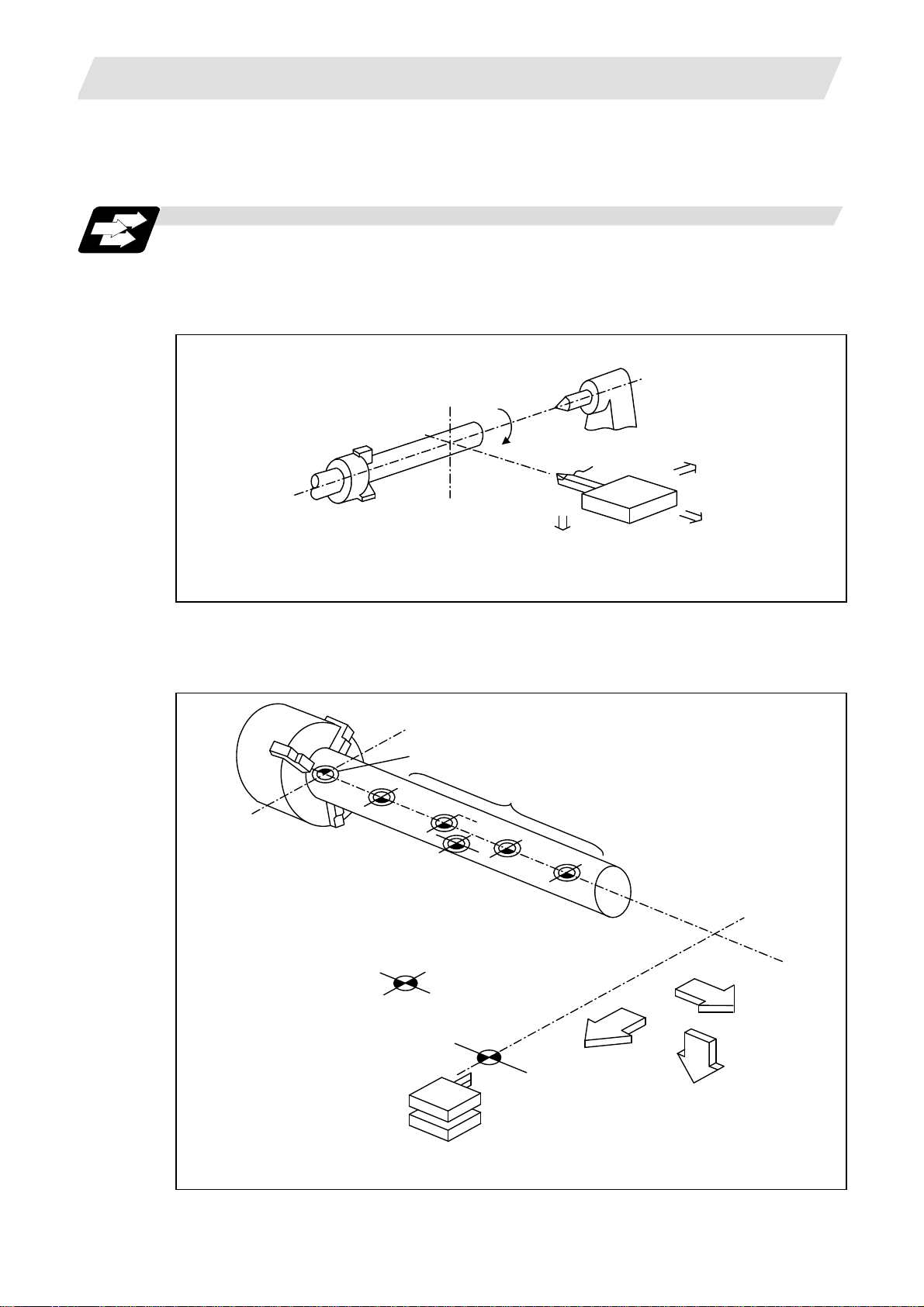
Function and purpose
In the case of a lathe, the axis parallel to the spindle is known as the Z axis and its forward
direction is the direction in which the turret moves away from the spindle stock while the axis at
right angles to the Z axis is the X axis and its forward direction is the direction in which it moves
away from the Z axis, as shown in the figure below.
1.1 Coordinate Word and Control Axis
indle stock
S
+Y
Tailstock
Tool
Tu
et
+Z
+X
Coordinate axes and polarities
Since coordinates based on the right hand rule are used with a lathe, the forward direction of the
Y axis in the above figure which is at right angles to the X-Z plane is downward. It should be
borne in mind that an arc on the X-Z plane is expressed as clockwise or counterclockwise as
seen from the forward direction of the Y axis. (Refer to the section on circular interpolation.)
Spindle nose
Machine zero point
G54
G55
G58
G52
Workpiece zero points (G54 to G59)
G59
Local coordinate system
(Valid in G54 to G59)
G30
2nd reference position
+Z
G28
+X
Reference position
(+Y)
Relationship between coordinates
1
Page 18
1. CONTROL AXES
X
X
X
X
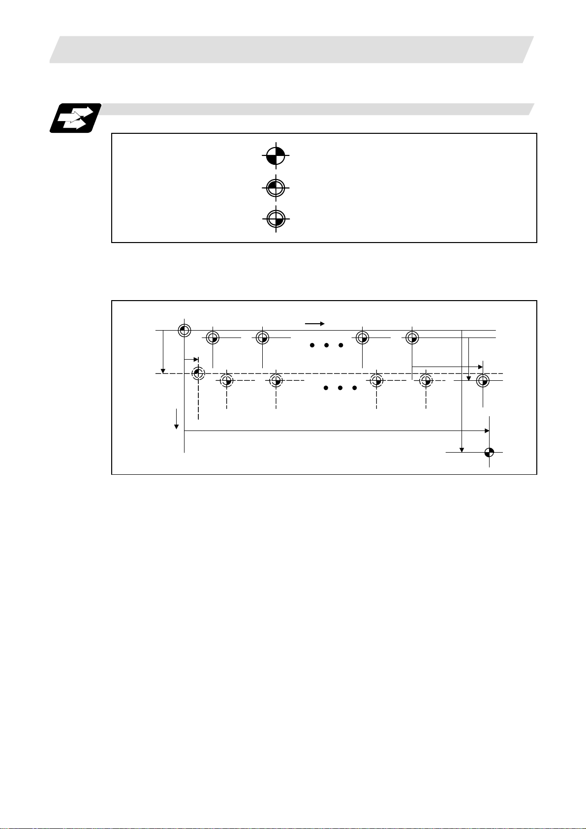
1.2 Coordinate Systems and Coordinate Zero Point Symbols
1.2 Coordinate Systems and Coordinate Zero Point Symbols
Function and purpose
: Reference position
: Machine coordinate origin
: Workpiece coordinate zero points
(G54 to G59)
Upon completion of the reference point return, the parameters are referred to and automatically
set for the basic machine coordinate system and workpiece coordinate systems (G54 to G59).
The basic machine coordinate system is set so that the first reference point is at the position
designated by the parameter from the basic machine coordinate zero point (machine zero point).
Basic mac hine
coordinate system
Hypothetical machine
coordinate system
(shifted by G92)
+
2
Z2
Machine zero point
Workpiece
coordinate
system
1 (G54)
Workpiece
coordinate
system
2 (G55)
+Z
Workpiece
coordinate
system
5 (G58)
Workpiece
coordinate
system6
(G59) Z
3
Z
3
Local
coordinate
system
1
(G52)
1
1st reference position
The local coordinate system (G52) is valid on the coordinate systems designated by the
commands for the workpiece coordinate systems 1 to 6.
Using the G92 command, the basic machine coordinate system can be shifted and made the
hypothetical machine coordinate system. At the same time, workpiece coordinate systems 1 to 6
are also shifted.
2
Page 19
2. INPUT COMMAND UNITS
2. INPUT COMMAND UNITS
2.1 Input Command Units
2.2 Input Setting Units
Function and purpose
These are the units used for the movement amounts in the program as commanded by the MDI
input. They are expressed in millimeters, inches or degrees (°).
Function and purpose
These are the units of setting data which are used, as with the compensation amounts, in
common for all axes.
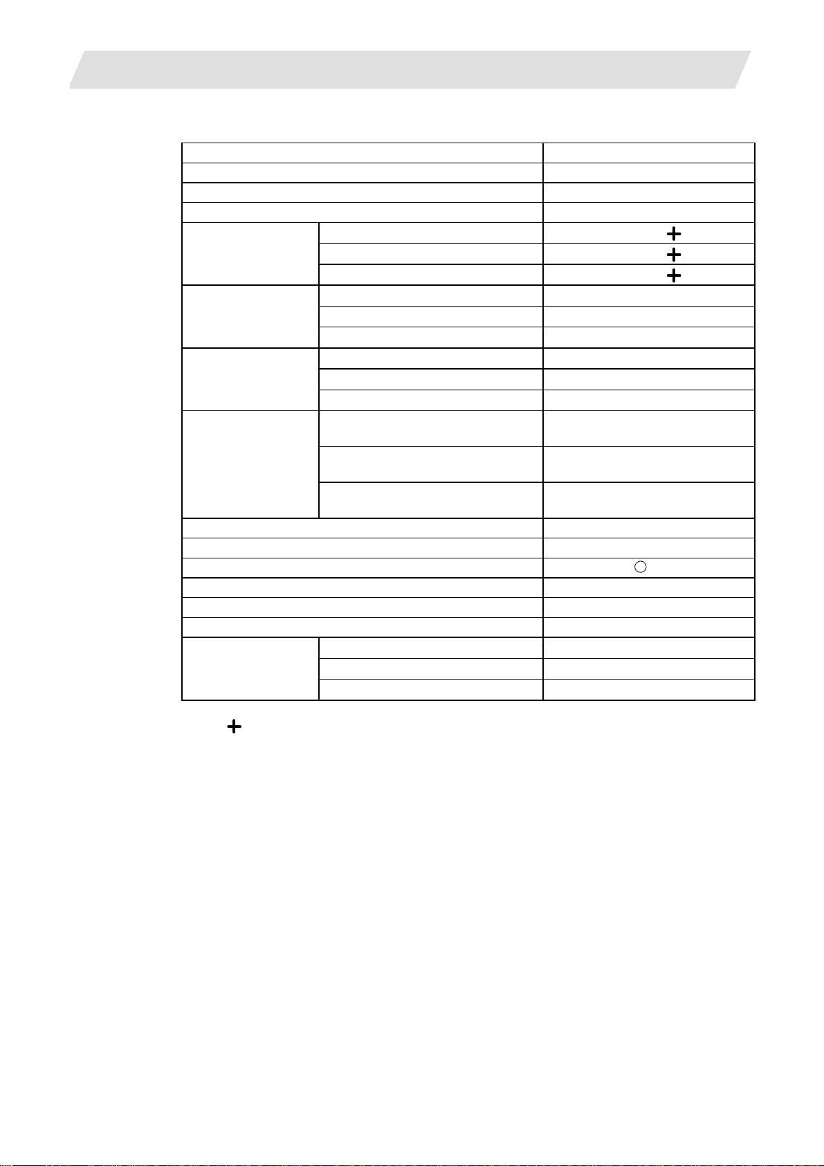
The input command unit can be selected for each axis and input setting units can be selected in
common for the axes by parameters from among the following types. (For further details on
settings, refer to the sections about control.)
Type
Input
command unit
Min. movement
unit
Input setting
unit
(Note 1) Inch/metric conversion is performed in either of 2 ways: conversion from the Parameter
screen ("Initial inch": valid only when the power is turned ON) and conversion using the
G command (G20 or G21).
However, when a G command is used for the conversion, the conversion applies only to
the input command units and not to the input setting units.
Consequently, the tool offset amounts and other compensation amounts as well as the
variable data should be preset to correspond to input setting unit.
#1003
cunit=10
=1 0.0001 0.0001 0.00001 0.00001 0.0001
IS-B 0.0005 0.001 0.0005 0.0001 0.001
IS-C 0.00005 0.0001 0.00005 0.00001 0.0001
IS-B 0.001 0.001 0.0001 0.0001 0.001
IS-C 0.0001 0.0001 0.00001 0.00001 0.0001
2.1 Input Command Units
Linear axis
Millimeter Inch
Diametrical
command
0.001 0.001 0.0001 0.0001 0.001
Radial
command
Diametrical
command
Radial
command
Rotation
axis
(°)
(Note 2) The millimeter and inch systems cannot be used together.
3
Page 20

3. DATA FORMATS
3. DATA FORMATS
3.1 Tape Codes
Function and purpose
The tape command codes used for this NC are combinations of alphabet letters (A, B, C...Z),
numbers (0, 1, 2...9) and signs ( +, –, /...). These alphabet letters, numbers and signs are referred
to as characters. Each character is represented by a combination of 8 holes which may, or may
not, be present.
These combinations make up what is called codes.
This NC employs the ISO code (R-840).
CAUTION
";", "EOB" and "%" "EOR" are expressions used for the explanation. The actual codes are "line
feed" and "%" for ISO.
Detailed description
(1) For the sake of convenience, a ";" has been used in the NC display to indicate End Of Block
(EOB/LF) which separates one block from another. Do not use the ";" key, however, in actual
programming but use the keys in the following table instead.
EOB/EOR keys and displays
3.1 Tape Codes
Code used
Key used
End Of Block LF or NL ;
End Of Record % %
(Note 1) If a code not given in Table of tape codes is assigned during operation, an Illegal
address error "P32" will result.
(Note 2) The following codes which exist with ISO can be designated by parameter:
[ (left square parenthesis)
] (right square parenthesis)
# (sharp sign)
∗ (asterisk)
= (equals sign)
: (colon)
! (exclamation mark) = (queuing code)
$ (dollar sign) = (code designating system number)
Any codes which overlap with existing codes or codes which result in parity H cannot be
designated.
ISO NC display
4
Page 21
3. DATA FORMATS
G
R
•
•••••••
•
•••
•
• •
•
•••••••••
•
•••••••
•
•
•••••••••••••••••
•
•
•
•••••••••••••••
•
•
•••••••••
(2) Significant data section (label skip function)
(3) Control out, control in
3.1 Tape Codes
All data up to the first EOB (;), after the power has been turned ON or after operation has
been reset, are ignored during automatic operation based on tape, memory loading
operation or during a search operation. In other words, the significant data section of a tape
extends from the character or number code after the first EOB (;) code after resetting to the
point where the reset command is issued.
When the ISO code is used, all data between control out "(" and control in ")" are ignored by
the NC, although these data appear on the setting display unit. Consequently, the command
tape name, number and other such data not directly related to control can be inserted in this
section.
This information will also be loaded, however, during tape loading.
The system is set to the "control in" mode when the power is turned ON.
Example of ISO code
••
• • • • • • • • • • • • • • • • • • • • • • • • • • • • • • • • • • • • • • • • • • • • • • • •
•• •••
•
•• •••
•
•
•
Operator information print-out example
L C S L
00X-85000Y-64000 (CUTTE
F R
• •
•• ••
••
•
• •• •
Information in this section is ignored and nothing is executed.
RE T URN)
P
• • •
• •• •
••• • ••
•••
•
•
••••••
••• • • •
F
••
•••••
•
(4) EOR (%) code
Generally, End Of Record is punched at both ends of the tape. It has the following functions:
(a) Rewind stop when rewinding tape (with tape handler)
(b) Rewind start during tape search (with tape handler)
(c) Completion of loading during tape loading
5
Page 22
3. DATA FORMATS
3.2 Program Formats
Function and purpose
The prescribed arrangement used when assigning control information to the NC unit is known as
the "program format", and the format used with the NC is called the "word address format."
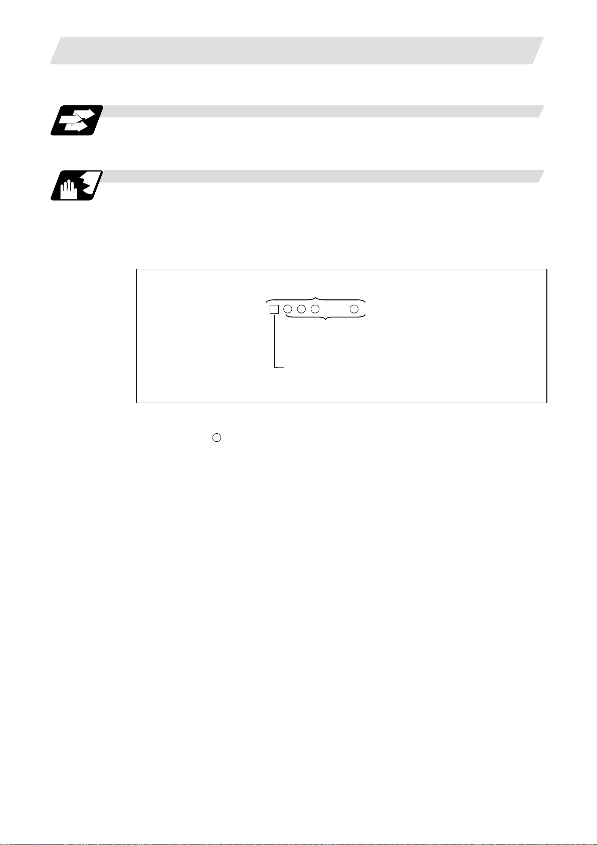
Detailed description
(1) Word and address
A word is a collection of characters arranged in a specific sequence. This entity is used as
the unit for processing data and for causing the NC to execute specific operations.
Each word used for the NC consists of an alphabet letter and a number of several digits
(sometimes with a "+" or "–" sign placed at the head of the number).
Word
Numerical (word data)
Alphabet (address)
3.2 Program Formats
------
Word configuration
The alphabet letter at the head of the word is the address. It defines the meaning of the
numerical information which follows it.
With the NC, "S
=" can be commanded for a multiple number of spindle commands
although this applies only to address S.
For details of the types of words and the number of significant digits of numbers used for this
NC, refer to Table 1 Format details and abbreviations.
(2) Blocks
A block is a collection of words. It includes the information which is required for the NC to
execute one specific operation. One block unit constitutes a complete command. The end of
each block is marked with an EOB (End-Of-Block) code.
(3) Programs
A program is a collection of several blocks.
(Note 1) If there is no number after the alphabetic character in the actual program, the value
following the alphabetic character will be handled as 0.
(Example) G28XYZ; → G28X0Y0Z0;
6
Page 23
3. DATA FORMATS
(Note 1) "
3.2 Program Formats
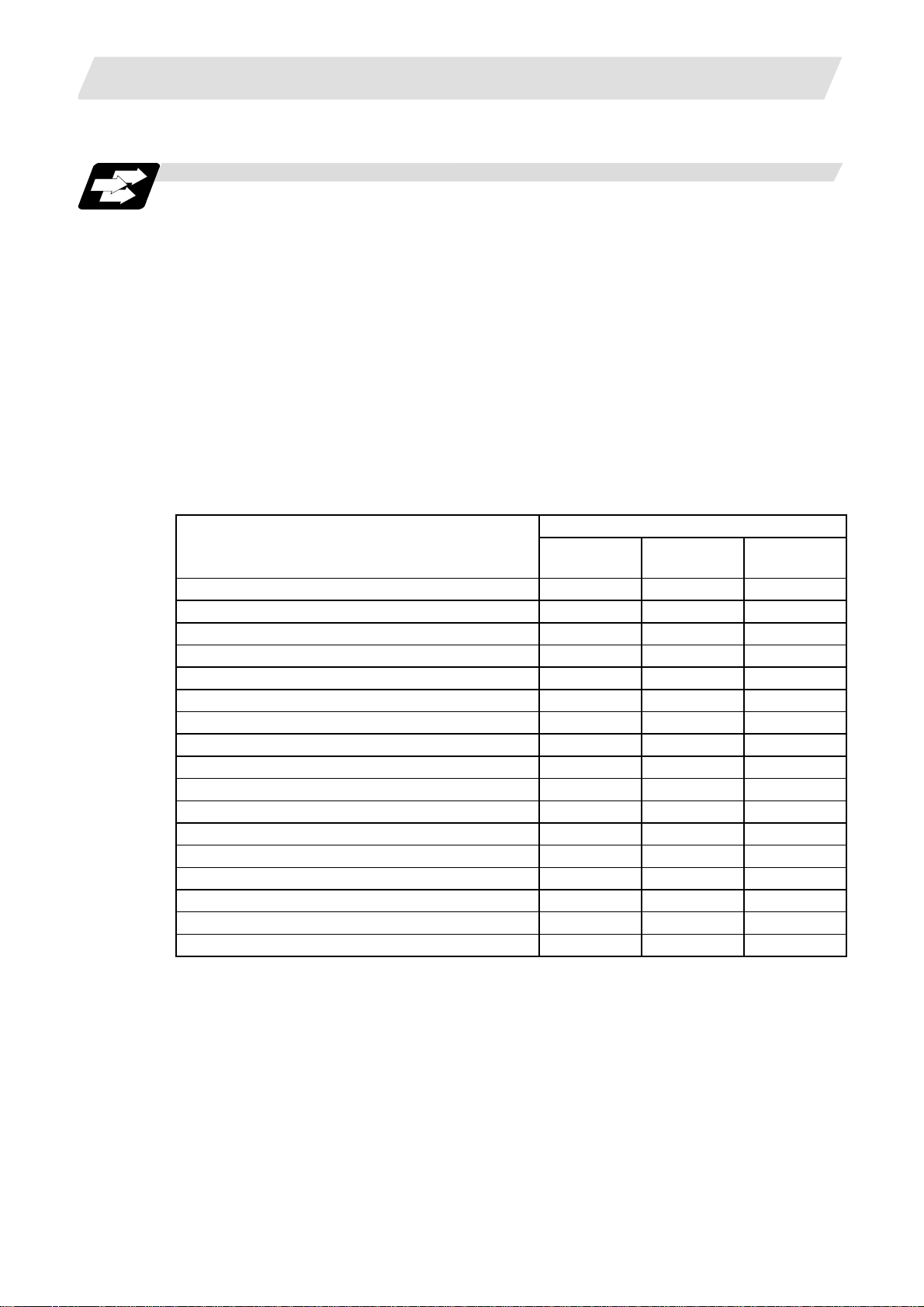
Table 1 Format details and abbreviations
Item Abbreviation
Program number O8
Sequence number N5
Preparatory function G3/G21
Movement
command
Movement
command, circular,
cutter radius
Dwell
Feed function
Input setting unit A 0.01°, mm
Input setting unit B 0.001°, mm
Input setting unit C 0.0001°, mm
Input setting unit A 0.01°, mm
Input setting unit B 0.001°, mm
Input setting unit C 0.0001°, mm
Input setting unit A 0.01°, mm
Input setting unit B 0.001°, mm
Input setting unit C 0.0001°, mm
Input setting unit A 0.01°, mm
X + 62 Z + 62
X + 53 Z + 53
X + 44 Z + 44
I + 62 K + 62
I + 53 K + 53
I + 44 K + 44
X + 53 P8
X + 53 P8
X + 53 P8
F62 (feed per minute)
+ 62
+ 53
+ 44
F43 (feed per rotation)
Input setting unit B 0.001°, mm
F53 (feed per minute)
F34 (feed per rotation)
Input setting unit C 0.0001°, mm
F54 (feed per minute)
F25 (feed per rotation)
Tool offset T1/T2
Miscellaneous function M2/M8
Spindle function S2/S5/S8 or S = n
Tool function T2/T8
2nd miscellaneous function A8/B8/C8
Subprogram P8H5L4
Fixed cycle
Input setting unit A 0.01°, mm
Input setting unit B 0.001°, mm
Input setting unit C 0.0001°, mm
R + 62 Q62 P8 L4
R + 53 Q53 P8 L4
R + 44 Q44 P8 L4
" denotes the A, B, C, Y, P or R.
(Note 2) The number of digits in the words is checked by the maximum number of digits in the
addresses.
7
Page 24

3. DATA FORMATS
3.3 Tape Storage Format
Function and purpose
(1) Storage tape and storage sections
The section which is stored into the memory extends from the character following the head
EOB after resetting as far as the EOR code.
The significant codes listed in Table of tape codes in Section 3.1 are the codes in the above
storage section which are actually stored into the memory. All other codes are ignored and
are not stored.
The data between control out "(" and control in ")" are stored into the memory.
3.4 Optional Block Skip
Function and purpose
This function selectively ignores specific blocks in a machining program which starts with the "/"
(slash) code.
Detailed description
(1) Provided that the optional block skip switch is ON, blocks starting with the "/" code are
ignored. They are executed if the switch is OFF.
Parity check is valid regardless of whether the optional block skip switch is ON or OFF.
When, for instance, all blocks are to be executed for one workpiece but specific blocks are
not to be executed for another workpiece, the same command tape can be used to machine
different parts by inserting the "/ " code at the head of those specific blocks.
Precautions for using optional block skip
(1) Put the "/" code at the head of the block. When inserted in a block, this is handled as a
division sign.
3.3 Tape Storage Format
(Example) N20G1X25./Z25.;............. NG
(This will be handled as 25. /0, so the error P283
"Divided by zero" will occur.)
/N20G1X25.Z25.;............. OK
(2) Parity checks (H and V) are conducted regardless of the optional block skip switch state.
(3) The optional block skip is processed immediately before the pre-read buffer.
Consequently, it is not possible to skip up to the block which has been read into the pre-read
buffer.
(4) This function is valid even during a sequence number search.
(5) AII blocks with the "/" code are also input and output during tape storing and tape output,
regardless of the state of the optional block skip switch.
8
Page 25
3. DATA FORMATS
3.5 Program/Sequence/Block Numbers (O, N)
3.5 Program/Sequence/Block Numbers (O, N)
Function and purpose
These numbers are used for monitoring the execution of the machining programs and for calling
both machining programs and specific stages in machining programs.
(1) Program numbers are classified by workpiece correspondence or by subprogram units, and
they are designated by the address "O" followed by a number with up to 8 digits.
(2) Sequence numbers are attached where appropriate to command blocks which configure
machining programs, and they are designated by the address "N" followed by a number with
up to 5 digits.
(3) Block numbers are automatically provided inside the NC itself. They are preset to "0" every
time a program number or sequence number is read, and they are counted up one at a time
unless program numbers or sequence numbers are commanded in blocks which are
subsequently read.
Consequently, all the blocks of the machining programs given in the table below can be
determined without further consideration by combinations of program numbers, sequence
numbers and block numbers.
NC input machining program
O12345678 (DEMO.PROG); 12345678 0 0
N100 G00 G90 X120. Z100.; 12345678 100 0
G94 S1000; 12345678 100 1
N102 G71 P210 Q220 I0.2 K0.2 D0.5 F600; 12345678 102 0
N200 G94 S1200 F300; 12345678 200 0
N210 G01 X0 Z95.; 12345678 210 0
G01 X20.; 12345678 210 1
G03 X50. Z80. K–15.; 12345678 210 2
G01 Z55.; 12345678 210 3
G02 X80. Z40. I15.; 12345678 210 4
G01 X100.; 12345678 210 5
G01 Z30.; 12345678 210 6
G02 Z10. K–15.; 12345678 210 7
N220 G01 Z0; 12345678 220 0
N230 G00 X120. Z150.; 12345678 230 0
N240 M02; 12345678 240 0
% 12345678 240 0
Program
No.
NC monitor display
Sequence
No.
Block
No.
9
Page 26
3. DATA FORMATS
3.6 G Code System
Function and purpose
These numbers are used to monitor the execution status of the machining program, or to call a
machining program or a specific process in the machining program.
There are 3 G code systems: 1, 2 and 3. Parameters "G code type 1", "G code type 2" and "G
code type 3" are used to set the applicable system.
G code system 3 is an additional specification.
The description of the G functions is based on G code system 2 which serves as the standard.
(Note 1) An alarm results when a G code not listed in the table is commanded. ("P34": Illegal G
code)
(Note 2) An alarm results when a G code not included in the additional specifications is
commanded.
(Example) An alarm ("P50 No spec: Inch/mm") occurs when the inch command G
3.6 G Code System
code (G20) is commanded although the inch/mm specifications have not
been provided.
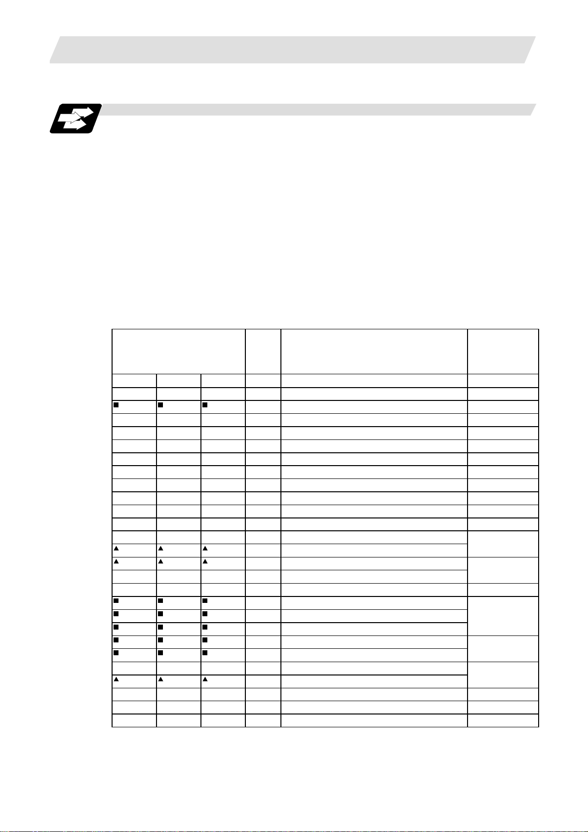
Table of G code systems
Reference
G code system (standard = 2) Group Function name
1 2 3
G00 G00 G00 01 Positioning 6.1
G01 G01 G01 01 Linear interpolation 6.2
G02 G02 G02 01 Circular interpolation (clockwise) 6.3, 6.4
G03 G03 G03 01 Circular interpolation (counterclockwise) 6.3, 6.4
G04 G04 G04 00 Dwell 8.1, 8.2
G09 G09 G09 00 Exact stop 7.8
G10 G10 G10 00 Data setting 12.5
G11 G11 G11 00 Data setting mode cancel 12.1
G12.1 G12.1 G12.1 19 Milling mode ON 6.8
G13.1 G13.1 G13.1 19 Milling mode OFF
G14 G14 G14 18 Balance cut OFF 17.4
G15 G15 G15 18 Balance cut ON
G16
G17 G17 G17 02 X-Y plane selection 6.5
G18 G18 G18 02 Z-X plane selection
G19 G19 G19 02 Y-Z plane selection
G20 G20 G70 06 Inch command
G21 G21 G71 06 Metric command
G22 G22 G22 04 Barrier check ON 15.1
G23 G23 G23 04 Barrier check OFF
G16 G16 02 Y-Z cylindrical plane selection 6.8
section in this
manual
(Section)
5.3
10
Page 27
3. DATA FORMATS
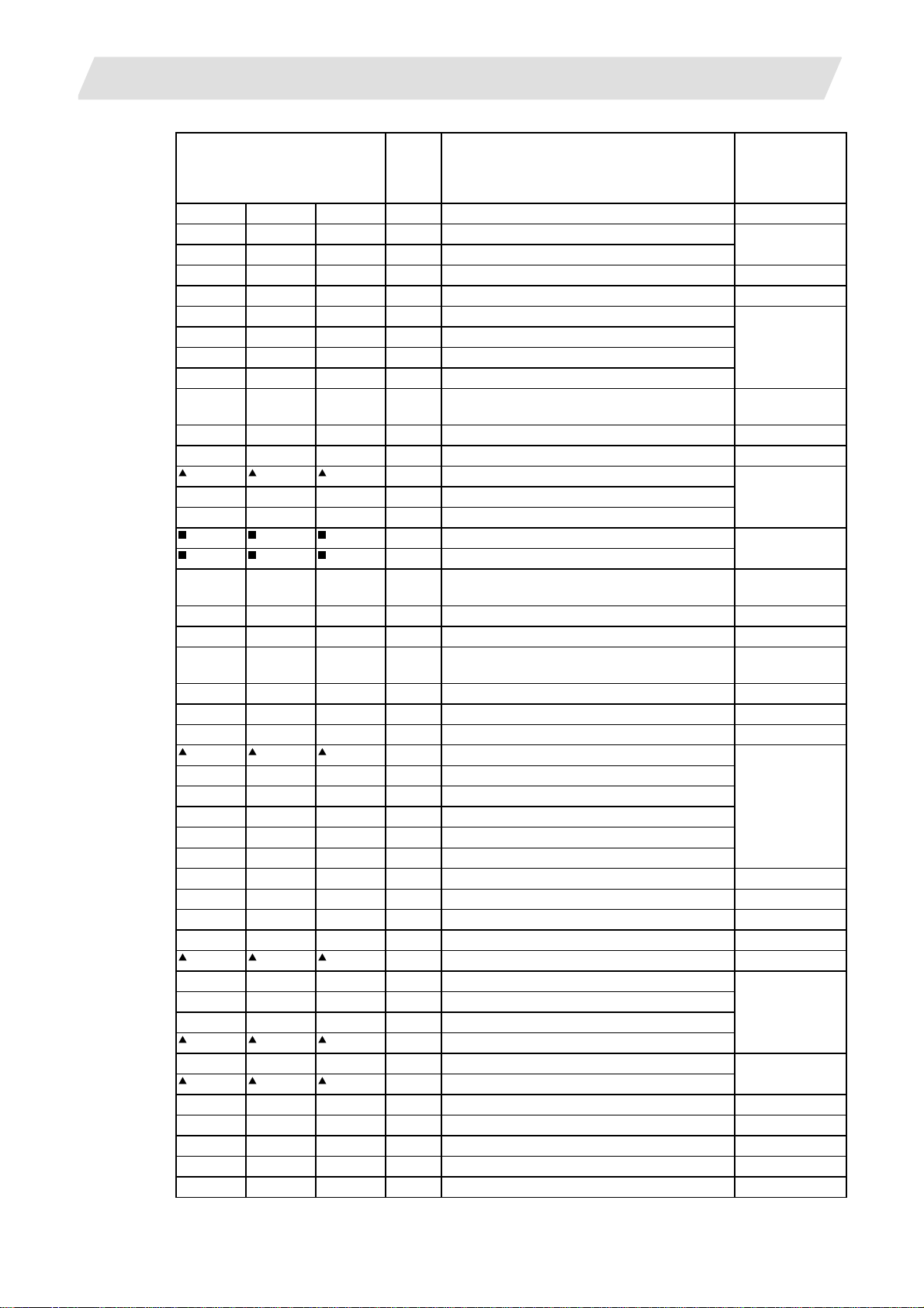
G code system (standard = 2) Group Function name
G27 G27 G27 00 Reference point return check 14.9
G28 G28 G28 00 Reference point return 14.7
G29 G29 G29 00 Return from reference point
G30 G30 G30 00 2nd reference point return 14.8
G31 G31 G31 00 Skip function 16.1
G32 G33 G33 01 Thread cutting 6.7
G34 G34 G34 01 Variable lead thread cutting
G35 G35 G35 01 Circular thread cutting (CW)
G36 G36 G36 01 Circular thread cutting (CCW)
G37 G37 G37 00
G40 G40 G40 07 Tool nose R compensation cancel 12.4
G41 G41 G41 07 Tool nose R compensation left
G42 G42 G42 07 Tool nose R compensation right
G43 G43 G43 08 2nd spindle control OFF 10.6
G44 G44 G44 08 2nd spindle control ON
G46 G46 G46 07
G50 G92 G92 00
G52 G52 G52 00 Local coordinate system setting 14.11
G53 G53 G53 00 Machine coordinate system selection 14.5
G54 G54 G54 12 Workpiece coordinate system selection 1 14.10
G55 G55 G55 12 Workpiece coordinate system selection 2
G56 G56 G56 12 Workpiece coordinate system selection 3
G57 G57 G57 12 Workpiece coordinate system selection 4
G58 G58 G58 12 Workpiece coordinate system selection 5
G59 G59 G59 12 Workpiece coordinate system selection 6
G61 G61 G61 13 Exact stop check mode 7.9
G64 G64 G64 13 Cutting mode 7.10
G65 G65 G65 00 Macro call 13.7.1
G66 G66 G66 14 Macro modal call A
G66.1 G66.1 G66.1 14 Macro modal call B
G67 G67 G67 14 Macro modal call cancel
G68 G68 G68 15 Facing turret mirror image ON 13.8
G69 G69 G69 15 Facing turret mirror image OFF
G70 G70 G72 09 Finishing cycle 13.2.4
G71 G71 G73 09 Longitudinal rough cutting cycle 13.2.1
G72 G72 G74 09 Face rough cutting cycle 13.2.2
G73 G73 G75 09 Stock removal in rough cutting cycle 13.2.3
3.6 G Code System
Reference
section in this
manual
(Section)
Automatic tool length offset, automatic tool
length measurement
Tool nose R compensation
(automatic selection of direction) ON
Coordinate system setting
Spindle clamp speed setting
16.3
12.4
14.6
10.4
11
Page 28

3. DATA FORMATS
G code system (standard = 2) Group Function name
G74 G74 G76 09 Face cut-off cycle 13.2.5
G75 G75 G77 09 Longitudinal cut-off cycle 13.2.6
G76 G76 G78 09 Compound thread cutting cycle 13.2.7
G76.1 G76.1 G76.1 09 2-system simultaneous thread cutting cycle 1 17.13
G76.2 G76.2 G76.2 09 2-system simultaneous thread cutting cycle 2
G80 G80 G80 09 Hole drilling cycle cancel 13.3.4
G83 G83 G83 09 Deep hole drilling cycle 1 (Z axis) 13.3.1
G79 G83.2 G83.2 09 Deep hole drilling cycle 2 13.4
G84 G84 G84 09 Tap cycle (Z axis) 13.3.2
G85 G85 G85 09 Boring cycle (Z axis) 13.3.3
G87 G87 G87 09 Deep hole drilling cycle (X axis) 13.3.1
G88 G88 G88 09 Tap cycle (X axis) 13.3.2
G89 G89 G89 09 Boring cycle (X axis) 13.3.3
G90 G77 G20 09 Longitudinal cutting fixed cycle 13.1.1
G92 G78 G21 09 Thread cutting fixed cycle 13.1.2
G94 G79 G24 09 Face cutting fixed cycle 13.1.3
G96 G96 G96 17 Constant surface speed control 10.3
G97 G97 G97 17 Constant surface speed control cancel
G98 G94 G94 05 Asynchronous feed 7.3
G99 G95 G95 05 Synchronous feed
G110 G110 G110 00 Cross machining command 17.6
G111 G111 G111 00 Axis name change 18.3
G113 G113 G113 00
G114.1 G114.1 G114.1 00 Spindle synchronization 17.8
G114.2 G114.2 G114.2 00
G114.3 G114.3 G114.3 00
G115 G115 G115 00 Waiting at designated start point 1 17.2
G116 G116 G116 00 Waiting at designated start point 2 17.3
G117 G117 G117 00
G125 G125 G125 00 Control axis synchronization 17.7
G126 G126 G126 00 Control axis superimposition 17.11
G164 G164 G164 00 Spindle superimposition 17.12
G173 G173 G173 00 Inclined coordinate rotation control 13.16
G200 to G200 to G999 G macro call 18.3
3.6 G Code System
Reference
section in this
manual
(Section)
– G90 G90 03 Absolute value command
– G91 G91 03 Incremental value command
– G98 G98 10 Hole drilling cycle initial return 13.3
– G99 G99 10 Hole drilling cycle reference point return
Spindle synchronization, tool/spindle
synchronization cancel
Tool/spindle synchronization 1 (polygon
machining)
Tool/spindle synchronization 2 (hobb
machining)
Miscellaneous function output during axis
movement
5.1
17.8-17.12
17.9
17.10
18.1, 18.2
12
Page 29

3. DATA FORMATS
(Note 1) The " " mark denotes a G code which is selected within each group when the power
3.6 G Code System
is turned ON or when resetting that initializes the modal commands is executed.
(Note 2) The "
" mark denotes a G code for which a parameter can be selected as the initial
status when the power is turned ON or when resetting that initializes the modal
commands is executed. Note that the inch/metric conversion can be made only when
the power is turned ON.
CAUTION
The commands with "no value after G", will be handled as "G00" during operation.
13
Page 30

3. DATA FORMATS
3.7 Precautions Before Machining
Precautions before machining
CAUTION
Before starting actual machining, always carry out dry operation to confirm the machining
program, tool offset amount and workpiece offset amount, etc.
When creating the machining program, select the appropriate machining conditions, and make
sure that the performance, capacity and limits of the machine and NC are not exceeded. The
examples do not consider the machining conditions.
3.7 Precautions Before Machining
14
Page 31

4. BUFFER REGISTER
A
A
4. BUFFER REGISTER
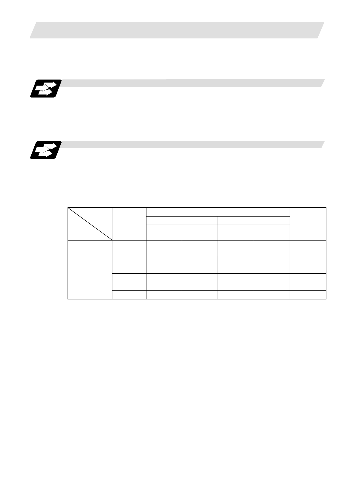
4.1 Pre-read Buffers
Function and purpose
During automatic processing, the contents of 1 block are normally pre-read so that program
analysis processing is conducted smoothly. However, during nose R compensation, a maximum
of 5 blocks are pre-read for the intersection point calculation including interference check.
The specifications of pre-read buffer are as follows:
(1) The data of 1 block are stored in this buffer.
(2) Only the significant data in the significant data section are stored into the pre-read buffer.
(3) When codes are sandwiched in the control in or control out mode and the optional block skip
function is ON, the data extending from the "/" (slash) code up to the EOB code are not read
into the pre-read buffer.
(4) The pre-read buffer contents are cleared with resetting.
(5) When the single block function is ON during continuous operation, the pre-read buffer stores
the following block data and then stops operation.
4.1 Pre-read Buffers
nalysis processin g
Max. 5 execution blocks
Pre-read
buffer 5
Buffer 4
Mode
Memory
Keyboard
MDI data
switching
Buffer 3
Buffer 2
Buffer 1
(Note)
Data equivalent to 1 block are stored
in 1 pre-read buffer.
rithmetic
processing
15
Page 32

5. POSITION COMMANDS
5. POSITION COMMANDS
5.1 Incremental/Absolute Value Commands
Function and purpose
There are 2 methods of issuing tool movement amount commands: the incremental value
command and the absolute value command.
The incremental value method applies for coordinates of a point which is to be moved and it
issues a command using the distance from the present point, on the other hand, the absolute
value method issues a command using the distance from the coordinate zero point. The following
figure shows what happens when the tool is moved from point P1 to point P2.
5.1 Incremental/Absolute Value Commands
Spindle
The incremental and absolute value commands for the X and Z axes are identified by addresses
when control parameter "#6 ABS/INC Addr." is ON and by G codes (G90/G91) when it is OFF.
Similarly, even with additional axes (C or Y axis), they are differentiated by addresses, or G
code.
X axis
Z
P2
Workpiece coordinate zero point
Incremental and absolute value commands
W
P1
U
2
X
Z axis
Absolute
value
Incremental
value
(Example)
X_____ W _____ ;
X axis Address X
Z axis Address Z
C/Y axis Address C/Y
X axis Address U
Z axis Address W
C/Y axis Address H/V
Command
system
Incremental value command for Z axis
Absolute value command for X axis
16
Remarks
For setting correspondence between addresses
and axes into machine parameters.
Absolute and incremental values can be used
together in the same block.
Page 33

5. POSITION COMMANDS
5.1 Incremental/Absolute Value Commands
Precautions
(1) Coordinate values can be omitted, in which case they are treated as "0".
The absolute and incremental value commands can be differentiated for any axis by the G90
and G91 commands.
G91 X___ W___ C___;
(Example) When the C axis has been differentiated by G90/G91.
(when incremental addresses have not been set)
Incremental value command for C axis
Incremental value command for Z axis
Absolute value command for X axis
17
Page 34

5. POSITION COMMANDS
r2r
5.2 Radius/Diameter Commands
Function and purpose
The cross sections of workpieces machined on a lathe are circular, and the diameter or radius
value of those circles can be used for movement commands in the X-axis direction. A radius
command will move the tool by the commanded amount only, but a diameter command will move
the tool both in the X-axis direction by an amount equivalent to one-half the command amount
only and in the Z-axis direction by the commanded amount only.
This system permits radius or diameter commands to be issued, depending on the parameter
setting. The figure below shows the command procedure when the tool is to be moved from point
P1 to point P2.
X axis
5.2 Radius/Diameter Commands
P1
Spindle
P2
Workpiece coordinate zero point
1
Z axis
X command U command Remarks
Radius Diameter Radius Diameter
X = r1 X = 2r1 U = r2 U = 2r2
Even when a diameter command has been
selected, only the U command can be
made a radius command by parameter.
Radius and diameter commands
Precautions
(1) In the above example, the tool moves from P1 to P2 in the minus direction of the X axis and
so when an incremental value is issued, the minus sign is given to the numerical value being
commanded.
(2) In this manual, diameter commands are used in descriptions of both the X and U axes for the
sake of convenience.
18
Page 35

5. POSITION COMMANDS
5.3 Inch/Metric Conversion (G20, G21)
Function and purpose
These G commands are used to switch between the inch and millimeter (metric) systems.
Command format
G20/G21;
G20 Inch command
G21 Metric command
Detailed description
The G20 and G21 commands merely select the command units. They do not select the Input
units.
G20 and G21 selection is meaningful only for linear axes and it is meaningless for rotation axes.
(Example) Relationship between input command units and G20/G21 commands (with decimal
point input type I)
5.3 Inch/Metric Conversion (G20, G21)
command unit
"cunit"
10
1
Axis type
Linear axes X100; 0.100mm 0.254mm 0.0039 inch 0.0100 inch
Rotation axes C100;
Linear axes X100; 0.0100mm 0.0254mm 0.00039 inch 0.00100 inch
Rotation axes C100;
Command
example
"Initial inch" OFF "Initial inch" ON Input
G21 G20 G21 G20
0.100° 0.100° 0.100° 0.100°
0.0100° 0.0100° 0.0100° 0.0100°
19
Page 36

5. POSITION COMMANDS
5.4 Decimal Point Input
Function and purpose
This function enables the decimal point command to be input. It assigns the zero point in
millimeter or inch units for the machining program input information that defines the tool paths,
distances and speeds.
A parameter selects whether type I (minimum input command unit) or type II (zero point) is to
apply for the least significant digit of data without a decimal point.
Command format
. Inch system
. Metric system
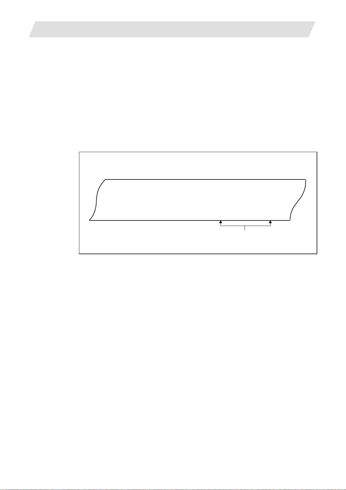
Detailed description
(1) The decimal point command is valid for the distances, angles, times and speeds in
machining programs.
5.4 Decimal Point Input
(2) Refer to the table "Addresses used and valid/invalid decimal point commands" for details on
the valid addresses for the decimal point commands.
(3) The number of significant digits in a decimal point command is shown below (for input
command unit CS-B).
Movement
Integer
MM
(milli-
meter)
INCH
(inch)
command (linear)
part
0 to
99999.
0 to
9999.
Decimal
part
.000
to .999
.0000
to .9999
Movement command
(rotation)
Integer
part
0 to
99999.
99999.
(359.)
Decimal
part
.000
to .999
.0 to .999
Feedrate Dwell (X)
Integer part Decimal part Integer part
0 to 60000. .000 to .999
0 to 999. .0000 to .9999
0 to 2362. .0000 to .9999
0 to 99.
.000000
to .999999
0. to 99999. .000 to .999
0 to 99. .000 to .999
Decimal
part
(Note) The top row of Feedrate is for feed per minute and the bottom row is for feed per
rotation.
(4) The decimal point command is valid even for commands defining the variable data used in
subprograms, etc.
(5) Decimal point commands for decimal point invalid addresses are processed as integer data
only and everything below the decimal point is ignored. Addresses which are invalid for the
decimal point are D, H, L, M, N, O, P, S and T. All variable commands, however, are treated
as data with decimal points.
Precautions
(1) If an arithmetic operator is inserted, the data will be handled as data with a decimal point.
(Example) G00 X123+0;........... This is the X axis 123mm command. It will not be 123μm.
20
Page 37

5. POSITION COMMANDS
Example of program
(1) Example of program for decimal point valid address
5.4 Decimal Point Input
Specification
division
Decimal point command 1
When 1 = 1μm When 1 = 10μm
Decimal point
command 2
1 = 1mm
Program example
G0 X123.45
(decimal points are all
X123.450mm X123.450mm X123.450mm
mm points)
X12.345mm
G0 X12345
(last digit is 1μm
X123.450mm X12345.000mm
unit)
#111=123, #112=5.55
X#111 Z#112
#113=#111+#112
(addition)
#114=#111–#112
(subtraction)
#115=#111∗#112
(multiplication)
#116=#111/#112
#117=#112/#111
(division)
X123.000mm,
Z5.550mm
X123.000mm,
Z5.550mm
X123.000mm,
Z5.550mm
#113 = 128.550 #113 = 128.550 #113 = 128.550
#114 = 117.450 #114 = 117.450 #114 = 117.450
#115 = 682.650 #115 = 682.650 #115 = 682.650
#116 = 22.162,
#117 = 0.045
#116 = 22.162,
#117 = 0.045
#116 = 22.162,
#117 = 0.045
21
Page 38

5. POSITION COMMANDS
Addresses used and valid/invalid decimal point commands
Add-
Decimal
ress
(Note 1) Decimal points are all valid in user macro arguments.
point
com-
mand
Valid Coordinate position data
A
Invalid 2nd miscellaneous function
Valid Angle data
Invalid MRC program number
Invalid Data setting, axis number
Valid Deep hole drilling cycle (2)
Valid Coordinate position data B
Invalid 2nd miscellaneous function
Valid Coordinate position data
C
Invalid 2nd miscellaneous function
Valid Corner chamfering amount ,C
Valid Program tool compensation
Valid Automatic tool length
D
Invalid Data setting, byte type data
E Valid Inch threads
Valid Feedrate F
Valid Thread lead
G Valid Preparatory function code
Valid Coordinate position data
H
Invalid Sequence numbers in
Invalid Data setting, bit type data
Valid Circular center coordinates
I
Valid Nose R compensation/tool
Valid Deep hole drilling cycle (2)
Valid Circular center coordinates
J
Valid Nose R compensation/
Invalid Deep hole drilling cycle (2)
Application
code
Safety distance
code
data
input
Nose R compensation
amount (incremental)
measurement,
deceleration range d
Precision thread lead
subprograms
radius compensation vector
components
First cut amount
nose radius compensation
vector components
Dwell at return point
Re-
marks
5.4 Decimal Point Input
Decimal
Add-
ress
point
com-
mand
Valid Circular center coordinates
K
Valid Nose R compensation/tool
Invalid Hole drilling cycle
Valid Deep hole drilling cycle (2)
Invalid Subprogram
L
Invalid Program tool compensation
Invalid Data setting selection L50
Invalid Data setting
M Invalid Miscellaneous function
Invalid Sequence numbers N
Invalid Data setting, data numbers
O Invalid Program numbers
Invalid Dwell time
P
Invalid Subprogram call program
Invalid 2nd reference point number
Invalid Constant surface speed
Invalid MRC finishing shape start
Valid Cut-off cycle
Invalid Compound thread cutting
Valid Compound thread cutting
Invalid Program tool compensation
Invalid Data setting, broad
Invalid Return sequence number
Valid Coordinate position data
Application
radius compensation vector
components
Number of repetitions
Second and subsequent cut
amounts
Number of repetitions
input type selection
2-word type data
codes
numbers
control, axis number
sequence number
Shift amount/cut amount
cycle, number of cutting
passes, chamfering, tool
nose angle
cycle
Thread height
input/ Offset number
classification number
from subprogram
Re-
marks
L2,
L10,
L11
4 bytes
22
Page 39

5. POSITION COMMANDS
Add-
Decimal
ress
point
command
Invalid Minimum spindle clamp
Q
Invalid MRC finishing shape end
Valid Cut-off cycle
Valid Compound thread cutting
Valid Compound thread cutting
Valid Deep hole drilling cycle (1)
Invalid Program tool compensation
Invalid Deep hole drilling cycle (2)
Valid R-designated arc radius
R
Valid Corner rounding circular
Valid Automatic tool length
Valid MRC longitudinal/face
Invalid MRC shaping division
Valid Cut-off cycle, return amount
Valid Cut-off cycle, escape
Valid Compound thread cutting
Valid Compound thread cutting
Valid Hole drilling cycle/deep
Valid Program tool radius
Valid Coordinate position data
Application
speed
sequence number
Shift amount/cut amount
cycle
Minimum cut amount
cycle
First cut amount
Cut amount of each pass
input
Hypothetical tool nose point
number
Dwell at cut point
radius
measurement, deceleration
range r
escape amount
number
amount
cycle, finishing allowance
cycle/turning cycle, taper
difference
hole drilling cycle (2),
distance to reference point
compensation input
Nose R compensation
amount (absolute)
Re-
marks
,R
5.4 Decimal Point Input
Decimal
Add-
ress
point
com-
mand
Invalid Spindle function codes
S
Invalid Maximum spindle clamp
Invalid Constant surface speed
Invalid Data setting, word type data 2 bytes
T Invalid Tool function codes
Valid Coordinate position data
U
Invalid 2nd miscellaneous function
Valid Program tool compensation
Valid Coordinate position data
V
Invalid 2nd miscellaneous function
Valid Program tool offset input
Valid Coordinate position data
W
Invalid 2nd miscellaneous function
Valid Program tool compensation
Valid Coordinate position data
X
Valid Dwell
Invalid 2nd miscellaneous function
Valid Program tool compensation
Valid Coordinate position data
Y
Invalid 2nd miscellaneous function
Valid Program tool compensation
Valid Coordinate position data
Z
Invalid 2nd miscellaneous function
Valid Program tool compensation
Application
speed
control, surface speed
codes
input
codes
codes
input
codes
input
codes
input
codes
input
Re-
marks
23
Page 40

6. INTERPOLATION FUNCTIONS
6. INTERPOLATION FUNCTIONS
6.1 Positioning (Rapid Traverse); G00
Function and purpose
This command is accompanied by coordinate words. It positions the tool along a linear or
non-linear path from the present point as the start point to the end point which is specified by the
coordinate words.
Command format
G00 Xx/Uu Zz/Ww;
x, u, z, w Coordinate values
The command addresses are valid for all additional axes.
Detailed description
(1) Once this command has been issued, the G00 mode is retained until it is changed by
another G function or until the G01, G02, G03 or G33 command in the 01 group is issued. If
the next command is G00, all that is required is simply that the coordinate words be
specified.
6.1 Positioning (Rapid Traverse); G00
(2) In the G00 mode, the tool is always accelerated at the start point of the block and
decelerated at the end point. Execution proceeds to the next block after it has been
confirmed that the command pulse of the present block is 0 and that the tracking error of the
acceleration/deceleration circuit is 0. The in-position width is set by parameter.
(3) Any G function (G83 to G89) in the 09 group is cancelled (G80) by the G00 command.
(4) Whether the tool moves along a linear or non-linear path is determined by parameter, but the
positioning time does not change.
(a) Linear path................ This is the same as linear interpolation (G01), and the speed is
limited by the rapid traverse rate of each axis.
(b) Non-linear path ......... The tool is positioned at the rapid traverse rate independently for
each axis.
(5) When no number following the G address, this is treated as G00.
CAUTION
The commands with "no value after G" will be handled as "G00" during operation.
24
Page 41

6. INTERPOLATION FUNCTIONS
Example of program
6.1 Positioning (Rapid Traverse); G00
+X
Turret
Start point
(+180, +300)
End point (+100, +150)
Workpiece
+Z
(Unit : mm)
Chuck
G00 X100000 Z150000; Absolute value command
G00 U-80000 W-150000; Incremental value command
(With an input setting unit of 0.001mm)
(Note 1) When the "G0 interpolation OFF" user parameter is OFF, the path along which the tool
is positioned is the shortest path connecting the start and end points. The positioning
speed is automatically calculated so that the shortest distribution time is obtained in
order that the commanded speeds for each axis do not exceed the rapid traverse rate.
When, for instance, the X-axis and Z-axis rapid traverse rates are both 9600mm/min,
the tool will follow the path in the figure below if the following is programmed:
G00 Z–300000 X400000; (With an input setting unit of 0.001mm)
End point
Actual X axis rate:
6400 mm/min
X
400
fx
Z
Start
300
fz
point
(Unit : mm)
Actual Z axis rate: 9600 mm/m i n
25
Page 42

6. INTERPOLATION FUNCTIONS
(Note 2) When the "G0 interpolation OFF" user parameter is ON, the tool will move along the
path from the start point to the end point at the rapid traverse rate of each axis.
When, for instance, the X-axis and Z-axis rapid traverse rates are both 9600mm/min,
the tool will follow the path in the figure below if the following is programmed:
G00 Z–300000 X400000; (With an input setting unit of 0.001mm)
End point
6.1 Positioning (Rapid Traverse); G00
Actual X axis rate:
9600 mm/min
400
X
fx
Z
Start
300
fz
point
(Unit : mm)
Actual Z axis rate: 9600 mm/ m in
(Note 3) The rapid traverse rate for each axis with the G00 command differs according to the
individual machine and so refer to the instruction manual issued by machine
manufacturer.
(Note 4) Rapid traverse (G00) deceleration check
Upon completion of the rapid traverse (G00), execute the next block after the
deceleration check time (Td) has elapsed.
The deceleration check time (Td) is as follows, depending on the acceleration/
deceleration type.
Linear acceleration/linear deceleration.............................. Td = Ts + α
Exponential acceleration/linear deceleration..................... Td = 2 × Ts + α
Exponential acceleration/exponential deceleration........... Td = 2 × Ts + α
Where Ts is the acceleration/deceleration time constant, α = 0 to 14ms
The time required for the deceleration check during rapid traverse is the longest among
the rapid traverse deceleration check times of each axis determined by the rapid
traverse acceleration/deceleration time constants and by the rapid traverse
acceleration/deceleration mode of the axes commanded simultaneously.
26
Page 43

6. INTERPOLATION FUNCTIONS
6.2 Linear Interpolation; G01
Function and purpose
This command is accompanied by coordinate words and a feedrate command. It makes the tool
move (interpolate) linearly from its present position to the end point specified by the coordinate
words at the speed specified by address F. In this case, the feedrate specified by address F
always acts as a linear speed in the tool center advance direction.
Command format
G00 Xx/Uu Zz/Ww
x, u, z, w, α Coordinate values
αα Ff; ("α" is an additional axis)
X axis
6.2 Linear Interpolation; G01
Z
W
Command point
U
/
2
X
Detailed description
Once this command is issued, the mode is maintained until another G function (G01, G02, G03,
G33) in the 01 group which changes the G01 mode is issued. Therefore, if the next command is
also G01 and if the feedrate is the same, all that is required to be done is to specify the
coordinate words. If no F command is given in the first G01 command block, program error "P62"
results.
The feedrate for a rotation axis is commanded by °/min (decimal point position unit). (F300 =
300°/min)
The G functions (G70 to G89) in the 09 group are cancelled (G80) by the G01 command.
Present position
Z axis
27
Page 44

6. INTERPOLATION FUNCTIONS
Example of program
(Example 1)
6.2 Linear Interpolation; G01
X axis
20.0
Present position
Z axis
50.0
(Unit: mm)
G01 X50.0 Z20.0 F300;
(Example 2) Cutting in the sequence of P
P
→ P1 , P4 → P0 is for tool positioning
0
→ P2 → P3 → P4 at 300mm/min feedrate
1
Turret
+X
240
200
140
100
P1
P2
P3
P0
+Z
P4
Input setting unit : 0.001mm
2209040 230160
(Unit: mm)
G00 X200000 Z40000;
G01 X100000 Z90000 F300;
Z160000;
X140000 Z220000;
G00 X240000 Z230000;
P
→ P1
0
→ P2
P
1
→ P3
P
2
→ P4
P
3
→ P0
P
4
28
Page 45

6. INTERPOLATION FUNCTIONS
r
6.3 Circular Interpolation; G02, G03
Function and purpose
These commands serve to move the tool along a circular.
Command format
G02 (G03) Xx/Uu Zz/Ww Ii Kk Ff;
G02 Clockwise (CW)
G03 Counterclockwise (CCW)
Xx/Uu
Circular end point coordinates, X axis (absolute value of workpiece
Zz/Ww Circular end point coordinates, Z axis (absolute value of workpiece
Ii Circular center, X axis (for I, radius command/incremental value of X
Kk Circular center, Z axis (for K, incremental value of Z coordinate at center as
Ff Feedrate
coordinate system for X, incremental value from present position for U)
coordinate system for Z, incremental value from present position for W)
coordinate at center as seen from start point)
seen from start point)
6.3 Circular Interpolation; G02, G03
X axis
End point
U/2
X
Z K
W
Cente
I
Start
point
Z axis
29
Page 46

6. INTERPOLATION FUNCTIONS
Detailed description
(1) G02 (or G03) is retained until another G command (G00, G01 or G33) in the 01 group that
changes its mode is issued.
The direction of the circular rotation is differentiated by G02 and G03:
G02: CW (Clockwise)
G03: CCW (Counterclockwise)
+X
Chuck
CCW(G03)
6.3 Circular Interpolation; G02, G03
Turret
+X
+X
Workpiece
CW(G02)
CW(G02)
CCW(G03)
Turret
+Z
+Z
+Z
+X
(2) An arc which extends for more than one quadrant can be executed with a single block
command.
(3) The following information is needed for circular interpolation.
(a) Rotation direction : Clockwise (G02) or counterclockwise (G03).
(b) Circular end point coordinates : Given by addresses X, Z, U, W.
(c) Circular center coordinates : Given by addresses I, K (incremental value
commands).
(d) Feedrate : Given by address F.
(4) A program error results when I, K or R is not commanded.
Consideration must be given to the sign for I and K since I is the distance in the X-axis
direction to the arc center as seen from the start point and K is the distance in the Z-axis
direction.
(5) No T commands can be issued in the G2/G3 modal status.
A program error results "P151" if a T command is issued in the G2/G3 modal status.
30
Page 47

6. INTERPOLATION FUNCTIONS
Example of program
6.3 Circular Interpolation; G02, G03
X axis
50.0
Workpiece
coordinate
120.0
zero point
20.0
Z axis
70.0 50.0
(Unit: mm)
G2 X120.0 Z70.0 I50.0 F200; Absolute value command
G2 U100.0 W-50.0 I50.0 F200; Incremental value command
31
Page 48

6. INTERPOLATION FUNCTIONS
;
A
p
;
X
t
(Note 1) The terms "clockwise" (G02) and "counterclockwise" (G03) used for circular operations
are defined as a case where in a right-hand coordinate system, the negative direction is
viewed from the positive direction of the coordinate axis which is at right angles to the
plane in question.
(Note 2) When the end point is the same position as the start point, a 360° circular (full circle) is
commanded when the center is commanded using l and K. In this case, always
command the end point.
(Note 3) The following occurs when the start and end point radius do not match in a circular
command:
(1) Program error "P70" results at the circular start point when error ΔR is greater than
the "G02/G03 Error" parameter value.
G02Z80.K50.
X
6.3 Circular Interpolation; G02, G03
larm stop
Start
point
Start
oint radius
Center End point
End point
Z
radius
ΔR
(2) Spiral interpolation in the direction of the commanded end point results when error
ΔR is less than the parameter value.
G02Z90.K50.
Spiral interpolation
End
Start
Start point radius
point
Z
Center
End poin
radius
point
R
Δ
Although the parameter setting range is from 0 to 100 (input unit), the parameter
values in the above examples are assumed to be extremely high in order to
facilitate understanding.
32
Page 49

6. INTERPOLATION FUNCTIONS
6.4 R-designated Circular Interpolation; G02, G03
6.4 R-designated Circular Interpolation; G02, G03
Function and purpose
Along with the conventional circular interpolation commands based on the circular center
coordinate (I, K) designation, these commands can also be issued by directly designating the
circular radius R.
Command format
G02 (G03) Xx/Uu Zz/Ww Rr Ff;
x/u X-axis end point coordinate
z/w Z-axis end point coordinate
r Circular radius
f Feedrate
33
Page 50

6. INTERPOLATION FUNCTIONS
Detailed description
The circular center is on the bisector line which is perpendicular to the line connecting the start
and end points of the circular. The point, where the circular with the specified radius whose start
point is the center intersects the perpendicular bisector line, serves as the center coordinates of
the circular command.
If the R sign of the commanded program is plus, the circular command is smaller than a
semicircle, if it is minus, the circular command is larger than a semicircle.
6.4 R-designated Circular Interpolation; G02, G03
Circular path when R sign is minus
02
Center
point
End point
Circular path when R sign is plus
Center point
01
Start point
L
r
The following condition must be met with an R-designated circular interpolation command:
≤ 1
L
2 × r
Where L is the line from the start point to end point.
If the above conditions are not satisfied and the arc center cannot be calculated, a program error
(P71) will occur.
If an R designation and I, K designation are given at the same time in the same block, the circular
command with the R designation takes precedence.
In the case of a full-circle command (where the start and end points match), an R designation
circular command will be completed immediately if it is issued and no operation will result. An I, K
designation circular command should therefore be used in such a case.
Example of program
(Example 1)
G03 Zz1 Xx1 Rr1 Ff1; R-designated arc on Z-X plane
(Example 2)
G02 Xx1 Zz1 Ii1 Kk1 Rr1 Ff1; R-designated arc on X-Z plane
(When the R designation and I, K designation are
contained in the same block, the R designation has
priority in processing.)
34
Page 51

6. INTERPOLATION FUNCTIONS
6.5 Plane Selection; G17, G18, G19
Function and purpose
These commands are used to select the control plane and the plane on which the circular exists.
If the 3 basic axes and the parallel axes corresponding to these basic axes are entered as
parameters, the commands can select the plane composed of any 2 axes which are not parallel
axes. If a rotation axis is entered as a parallel axis, the commands can select the plane
containing the rotation axis.
These commands are used to select:
• The plane for circular interpolation
• The plane for nose R compensation
• The plane for milling interpolation
Command format
G17; (I-J plane selection)
G18; (K-I plane selection)
G19; (J-K plane selection)
6.5 Plane Selection; G17, G18, G19
I, J and K indicate each basic axis or parallel axis.
When the power is turned ON or when the system is reset, the plane set by the control
parameters (Initial Z-X plane, Initial Y-Z plane) is selected. If neither of these has been set, the
X-Y plane is selected.
J
G03
G02
I
G17 (I-J) plane G18 (K-I) plane G19 (J-K) plane
I
G03
G02
K
K
G03
G02
J
35
Page 52

6. INTERPOLATION FUNCTIONS
Parameter entry
Basic axis Parallel axis
I X Y
J Y
K Z
Fig. 1 Examples of plane
selection parameter entry
Plane selection system
This section describes the plane selection for the parameter entry samples shown in Fig. 1.
(1) Axis addresses assigned in the same block as the plane selection (G17, G18, G19)
command determine which of the basic axes or parallel axes are to be in the actual plane
selected.
(Example)
6.5 Plane Selection; G17, G18, G19
Basic axes and parallel axes can be entered in
the parameters. The same axis name can be
entered in duplication, but when it is assigned in
duplication, the plane is determined by plane
selection system (4).
It is not possible to set axes, which have not
been entered, as control axes.
X
G18XZ;
G03
G02
Z
Y
G18YZ;
G02
G03
G19YZ;
Z
G03
G02
Z
Y
(2) Plane selection is not performed with blocks in which the plane selection G code (G17, G18,
G19) is not assigned.
G18X_Z_; Z-X plane
Y_Z_; Z-X plane (no plane change)
(3) When the axis addresses are omitted in the block containing the plane selection G codes
(G17, G18, G19), it is assumed that the axis addresses of the 3 basic axes have been
assigned.
G18; (Z-X plane = G18XZ;)
(4) When the basic axes or their parallel axes are duplicated and assigned in the same block as
the plane selection G code (G17, G18, G19), the plane is determined in the order of basic
axes, and then parallel axes.
G18XYZ; The Z-X plane is selected.
Therefore, the Y movement is unrelated to the selected plane.
(Note 1) When the "#8121 Initial Z-X plane" in the control parameter is kept ON, the G18 plane
is selected when the power is turned ON or when the system is reset.
36
Page 53

6. INTERPOLATION FUNCTIONS
Y
6.6 Helical interpolation; G17, G18, G19, and G02, G03
6.6 Helical interpolation; G17, G18, G19, and G02, G03
Function and purpose
With three orthogonal axes, large diameter screws and solid cams can be machined with
simultaneous 3-axis control. With this control, circular interpolation is carried out with two random
axes, and at the same time, linear interpolation is carried out with the other axis in
synchronization with the circular interpolation.
Z
End point
Command program path
Start point
X
X-Y plane projected path in
command program
Command format
G17 G02 (G03) Xx/Uu Yy/Vv Zz/Ww Ii Jj Pp Ff;
G17 Arc plane (G17: X-Y plane, G18: Z-X plane, G19: Y-Z plane) (Note 2)
G02 (G03) Arc rotation direction (G02: clockwise, G03: counterclockwise) (Note 3)
Xx/Uu, Yy/Vv Arc end point coordinates
Zz/Ww Linear axis end point
Ii, Jj Arc center coordinates
Pp Number of pitches
Ff Feedrate
(Note 1) In this manual, the following setting descriptions are used. I axis: X, J axis: Y, K axis: Z
(Note 2) The linear interpolation axis is the other axis not included in the plane selection.
Arc plane Linear interpolation axis
G17 X-Y plane Z axis
G18 Z-X plane Y axis
G19 Y-Z plane X axis
(Note 3) The rotation direction is that looking at the arc plane in the linear interpolation axis'
positive to negative direction.
37
Page 54

6. INTERPOLATION FUNCTIONS
Explanation of addresses
Address
X/U
Y/V
Z/W Linear axis end
I
J
P Number of
F Feedrate Speed command range
* Calculating the pitch (I1)
Address
meaning
Arc end point
coordinates
point
coordinates
Arc center
coordinates
pitches (*)
6.6 Helical interpolation; G17, G18, G19, and G02, G03
Command range (unit) Remarks
Coordinate command range
(mm/inch)
(Decimal point command
valid)
Coordinate command range
(mm/inch)
(Decimal point command
valid)
Coordinate command range
(mm/inch)
(Decimal point command
valid)
0 to 99 1. If a value that exceeds the command range is
(mm/inch, inch/min)
(Decimal point command
valid)
1. If a value that exceeds the command range is
commanded, a program error will occur. (P35
Setting value range over)
2. If an axis other than one which can be
controlled with the command system is
commanded, a program error will occur. (P33
Format error).
1. If a value that exceeds the command range is
commanded, a program error will occur. (P35
Setting value range over)
2. If an axis other than one which can be
controlled with the command system is
commanded, a program error will occur. (P33
Format error).
1. If a value that exceeds the command range is
commanded, a program error will occur. (P35
Setting value range over)
2. If an axis other than one which can be
controlled with the command system is
commanded, a program error will occur. (P33
Format error).
3. Input a radius value.
4. An arc radius value command (R command)
cannot be used for the arc center coordinates.
commanded, a program error will occur. (P35
Setting value range over)
2. When omitted, this will be handled as P0.
1. Command the speed in the direction of each
axis' composite element as the feedrate.
2. If a value that exceeds the command range is
commanded, a program error will occur. (P35
Setting value range over)
(Example: X-Y plane)
Y
Number of
pitches (P1)
End point
X
Start point
Z
Command program path
Pitch (l1)
Y
Command program’s
X-Yplane projection path
θ
End point (xe, ye)
p
Start point (xs, ys)
X
l1 = z1/((2π · p1 + θ)/2π)
θ = θe – θs = arctan (ye/xe) – arctan (ys/xs) (0 ≤ θ < 2π)
Whereas, ys and xs indicate the start point coordinates, ye and xe indicate the end point
coordinates, z1 indicates the linear axis end point coordinates, and p1 indicates the number of
pitches. θe and θs each indicate the phase difference from the arc center coordinates.
38
Page 55

6. INTERPOLATION FUNCTIONS
j
j
Detailed description
The following type of movement will take place when the following type of command is issued.
G17 G02 Xx Yy Zz Ii Jj Pp Ff;
6.6 Helical interpolation; G17, G18, G19, and G02, G03
Z
Command program path
Y
End point
Start point
X
Z
End
point
i
Command program’s
X-Y plane projection path
Number of
pitches P
W
Y
i
Start point
p
X
The left drawing shows the process as an exploded view, and the right drawing shows the arc
plane from directly above.
Using the point designated as the arc center coordinates as the center, the axis starts to rotate at
the feedrate f, and after uniformly cutting from the start point to the end point with the number of
pitches designated with p, the axis stops.
Example of program
(Example 1)
G17 G02 U0. V0. W150. I-100.
Normal command
J0. P3 F300;
End point
Z
Command program path
Y
P(=3)
100.
Start point
150.
Y
X
Command program’s
X-Y plane projection path
W
100.
End point
X
Start point
The left drawing shows the process as an exploded view, and the right drawing shows the
arc plane from directly above.
At the start of the block, the axis centers at the point -100mm in the X axis direction and
0mm in the Y axis direction from the workpiece coordinates (start point), and starts cutting at
the feedrate 300mm/min while rotating.
While carrying out circular interpolation, the axis uniformly cuts three-step pitches while
moving 100mm in the Z axis direction, and then stops.
39
Page 56

6. INTERPOLATION FUNCTIONS
X
(Example 2)
6.6 Helical interpolation; G17, G18, G19, and G02, G03
G17 G02 U-50. V200. W100.
When P command is omitted
I-100. J100. F1500;
Z
Start
point
Command program path
End point
100.
Y
Command program’s X-Y
plane projection path
Y
End point
W
X
J100.
I-100.
Start point
The left drawing shows the process as an exploded view, and the right drawing shows the
arc plane from directly above.
At the start of the block, the axis centers at the point -100mm in the X axis direction and
100mm in the Y axis direction from the workpiece coordinates (start point), and starts cutting
at the feedrate 1500mm/min while rotating.
Since the P command is omitted, the number of pitches is 0. Thus, the axis will cut 100mm in
the Z axis direction while carrying out circular interpolation, and then stops.
Precautions and restrictions
(1) When the P designation is omitted, the setting will be the same as P0.
(2) When the arc center coordinates are omitted, "P70 Arc radius error" will occur.
(3) Circular machining is possible by omitting the arc end point coordinates.
(4) If P0 is commanded when the start point and end point coordinates are the same, linear
interpolation will take place only in the direction of the linear interpolation axis. If P0 is
commanded when the start point and end point coordinates differ, helical interpolation will
take place from the start point to end point in one cycle.
(5) A circular interpolation radius command (R command) cannot be issued when carrying out
helical interpolation.
(6) If the linear interpolation axis is omitted, the movement will be the same as normal circular
interpolation. However, the axis will stop at the end point after carrying out circular
interpolation the number of times commanded with P.
(7) If a height axis is set with the same axis designating an arc plane, the latter setting will
become valid and normal circular interpolation will take place. However, the circle will be
traced only the number of times designated with the P command.
(8) The feedrate is the speed in the direction of each axis' composite element.
40
Page 57

6. INTERPOLATION FUNCTIONS
α
δ
6.7 Thread Cutting
6.7.1 Constant lead thread cutting; G33
Function and purpose
The G33 command exercises feed control over the tool which is synchronized with the spindle
rotation and so this makes it possible to conduct constant-lead straight thread cutting, tapered
thread cutting, and continuous thread cutting.
F/E
6.7 Thread Cutting
F/E
Straight thread Scrolled thread Continuous thread
F/E
Command format
G33 Zz/Ww Xx/Uu Ff Qq ; (Normal lead thread cutting commands)
Zz, Ww, Xx, Uu Thread end point addresses and coordinates
Ff Lead of long axis (axis which moves most) direction
Qq Thread cutting start shift angle (0.001 to 360.000°)
G33 Zz/Ww Xx/Uu Ee Qq ; (Precision lead thread cutting commands)
Zz, Ww, Xx, Uu Thread end point addresses and coordinates
Ee Lead of long axis (axis which moves most) direction
Qq Thread cutting start shift angle (0.001 to 360.000°)
X axis
End
W
point
U/2
Start point
Z
2
δ
1
Z axis
X
41
Page 58

6. INTERPOLATION FUNCTIONS
Detailed description
(1) The E command is also used for the number of threads in inch thread cutting, and whether
the threads or precision lead is to be designated can be selected by parameter setting. (The
parameter "#8114 Precision thrd cut E" is set to ON for precision lead designation.)
(2) The lead in the long axis direction is commanded for the tapered thread lead.
X
U/2
a°
Tapered thread section
W
Z
When a < 45° lead is in Z-axis direction
When a > 45° lead is in X-axis direction
When a = 45° lead can be in either Z or X-axis direction.
6.7 Thread Cutting
Input unit
system
Command
address
Minimum
command
unit
Command
range
Input unit
system
Command
address
Minimum
command
unit
Command
range
Thread cutting metric input
A (0.01mm) B (0.001mm) C (0.0001mm)
F (mm/rev) E (mm/rev)
1 (= 0.001),
(1.=1.000)
0.001 to
9999.999
1 (= 0.0001),
(1.=1.0000)
0.0001 to
9999.9999
E (threads/
inch)
1 (= 1),
(1.=1.0)
0.1 to
9999999.9
F (mm/rev) E (mm/rev)
1 (= 0.0001),
(1.=1.0000)
0.0001 to
999.9999
1 (= 0.00001),
(1.=1.00000)
0.00001 to
999.99999
E (threads/
inch)
1 (= 1),
(1.=1.00)
0.01 to
999999.99
F (mm/rev) E (mm/rev)
1 (= 0.00001),
(1.=1.00000)
0.00001 to
99.99999
1(=0.000001),
(1.=1.000000)
0.000001 to
99.999999
E (threads/
inch)
1 (= 1),
(1.=1.000)
0.001 to
99999.999
Thread cutting inch input
A (0.001inch) B (0.0001inch) C (0.00001inch)
F (inch/rev) E (inch/rev)
1(=0.00001),
(1.=1.00000)
0.00001 to
999.99999
1(=0.000001)
(1.=1.000000)
0.000001 to
99.999999
E (threads/
inch)
1 (= 1),
(1.=1.000)
0.001 to
99999.999
F (inch/rev) E (inch/rev)
1(=0.000001),
(1.=1.000000)
0.000001 to
99.999999
1(=0.0000001),
(1.=1.0000000)
0.0000001 to
9.9999999
E (threads/
inch)
1 (= 1),
(1.=1.0000)
0.0001 to
9999.9999
F (inch/rev) E (inch/rev)
1(=0.0000001),
(1.=1.0000000)
0.0000001 to
9.9999999
1(=0.00000001),
(1.=1.00000000)
0.00000001 to
0.99999999
E (threads/
inch)
1(=1),
(1.=1.00000)
0.001
to999.99999
(Note 1) It is not possible to assign a lead where the feedrate as converted into feed per minute
exceeds the maximum cutting feedrate.
(3) The constant surface speed control function should not be used for tapered thread cutting
commands or scrolled thread cutting commands.
(4) The spindle speed should be kept constant throughout from the rough cutting until the finishing.
42
Page 59

6. INTERPOLATION FUNCTIONS
(5) If the feed hold function is employed during thread cutting to stop the feed, the thread ridges
will lose their shape. For this reason, feed hold does not function during thread cutting.
If the feed hold switch is pressed during thread cutting, block stop will result at the end point of
the block following the block in which thread cutting is completed (no longer G33 mode).
(6) The converted cutting feedrate is compared with the cutting feed clamp speed when thread
cutting starts, and if it is found to exceed the clamp speed, an operation error will result.
(Note 1)
(7) In order to protect the lead during thread cutting, a cutting feedrate which has been
converted may sometimes exceed the cutting feed clamp speed.
(8) An illegal lead is normally produced at the start of the thread cutting and at the end of the
cutting because of servo system delay and other such factors.
Therefore, it is necessary to command a thread length which is determined by adding the
illegal lead lengths δ
(9) The spindle speed is subject to the following restriction:
1 ≤ R ≤
Where R ≤ Permissible speed of encoder (r/min)
R = Spindle speed (r/min)
Thread lead = mm or inches
Maximum feedrate = mm/min or inch/mm
(this is subject to the restrictions imposed by the machine specifications).
(10) Dry run is valid for thread cutting but the feedrate based on dry run is not synchronized with
the spindle rotation.
The dry run signal is checked at the start of thread cutting and any switching during thread
cutting is ignored.
and δ2 to the required thread length.
1
Maximum feedrate
6.7 Thread Cutting
(11) Synchronous feed applies for the thread cutting commands even with an asynchronous
feed command (G94).
(12) For the spindle override during thread cutting, select either valid or invalid (100% fixed) with
the parameters. When the override is valid, the thread will not be cut correctly because of a
delay in the servo system if the override is changed during thread cutting. When the
override is invalid, the override will change to 100% when operation with an override other
than 100% is started. Thus, the thread will not be cut correctly due to a delay in the servo
system.
(13) When a thread cutting command is programmed during nose R compensation, the
compensation is temporarily canceled and the thread cutting is executed.
(14) When the mode is switched to another automatic mode while G33 is executed, the following
block which does not contain a thread cutting command is first executed and then the
automatic operation stops.
(15) When the model is switched to the manual mode while G33 is executed, the following block
which does not contain a thread cutting command is first executed and then the automatic
operation stops. In the case of a single block, the following block which does not contain a
thread cutting command is first executed and then the automatic operation stops.
(16) The thread cutting command waits for the single rotation synchronous signal of the rotation
encoder and starts movement.
However, movement starts without waiting for this signal when another system issues a
thread cutting command during ongoing thread cutting by one particular system. Therefore,
thread cutting commands should not be issued by a multiple number of systems.
43
Page 60

6. INTERPOLATION FUNCTIONS
Example of program
X axis
6.7 Thread Cutting
20.0
Z axis
90.0
40.0 50.0
(Unit: mm)
G33 X90.0 Z40.0 E12.34567; Absolute value command
G33 U70.0 W-50.0 E12.34567; Incremental value command
44
Page 61

6. INTERPOLATION FUNCTIONS
α
δ
6.7.2 Inch thread cutting; G33
Function and purpose
If the number of threads per inch in the long axis direction is assigned in the G33 command, the
feed of the tool synchronized with the spindle speed will be controlled, which means that
constant-lead straight thread cutting, tapered thread cutting, and continuous thread cutting can
be performed.
Command format
G33 Zz/Ww Xx/Uu Ee Qq;
Zz, Ww, Xx, Uu Thread end point addresses and coordinates
Ee Number of threads per inch in direction of long axis (axis which
Qq Thread cutting start shift angle (0.001 to 360.000°)
6.7 Thread Cutting
moves most) (decimal point command can also be assigned)
X axis
End
W
point
X
U/2
Start point
Z
2
δ
1
Z axis
Detailed description
(1) The number of threads in the long axis direction is assigned as the number of threads per
inch.
(2) The E code is also used to assign the precision lead length, and whether the thread number
or precision lead length is to be designated can be selected by parameter setting. (The
parameter "G33 Precision thrd cut E" is set OFF for thread number designation.)
(3) The E command value should be set within the lead value range when the lead is converted.
(4) See Section 6.7.1 on lead thread cutting for other details.
45
Page 62

6. INTERPOLATION FUNCTIONS
Example of program
X axis
6.7 Thread Cutting
40.0 50.0
G33 X90.0 Z40.0 E12.0; Absolute value command
G33 U70.0 W-50.0 E12.0; Incremental value command
6.7.3 Continuous thread cutting
Function and purpose
Continuous thread cutting is possible by assigning thread cutting commands continuously.
In this way, it is possible to cut special threads whose lead or shape changes.
20.0
Z axis
90.0
(Unit: mm)
G33
G33
G33
46
Page 63

6. INTERPOLATION FUNCTIONS
6.7.4 Variable lead thread cutting
Function and purpose
Variable lead thread cutting is enabled by a command specifying a lead increment or decrement
amount per turn of the screw.
Command format
G34 X/U____ Z/W____ F/E____ K____ ;
X/U X coordinate at the end of thread cutting
Z/W Z coordinate at the end of thread cutting
F/E Standard thread lead
K Lead increment or decrement amount per turn of the screw
Non-lead axis
6.7 Thread Cutting
Lead axis
F+3.5K
Lead speed
F+4K
F+2.5K F+1.5K F+0.5K
F+3K F+2K F+K F
47
Page 64

6. INTERPOLATION FUNCTIONS
√
Detailed description
(1) The command range is as shown below.
Thread cutting metric input
6.7 Thread Cutting
Input unit
system
Command
address
Minimum
command unit
Command
range
Input unit
system
Command
address
Minimum
command unit
Command
range
A (0.01mm) B (0.001mm) C (0.0001mm) A/B/C
F (mm/rev) E (mm/rev) F (mm/rev) E (mm/rev) F (mm/rev) E (mm/rev)
1 (=0.001)
(1.=1.000)
0.001 to
9999.999
1 (=0.0001)
(1.=1.0000)
0.0001 to
9999.9999
1 (=0.0001)
(1.=1.0000)
0.0001 to
999.9999
1 (=0.00001)
(1.=1.00000)
0.00001 to
999.99999
1 (=0.00001)
(1.=1.00000)
0.00001 to
99.99999
1 (=0.000001)
(1.=1.000000)
0.000001 to
99.999999
K (n ∗ mm/rev)
n: Number of
pitches
Same as F or E
(signed)
Thread cutting inch input
A (0.001inch) B (0.0001inch) C (0.00001inch) A/B/C
F (inch/rev) E (inch/rev) F (inch/rev) E (inch/rev) F (inch/rev) E (inch/rev)
1 (=0.00001)
(1.=1.00000)
0.00001 to
999.99999
1 (=0.000001)
(1.=1.000000)
0.000001 to
99.999999
1 (=0.000001)
(1.=1.000000)
0.000001 to
99.999999
1 (=0.0000001)
(1.=1.0000000)
0.0000001 to
9.9999999
1 (=0.0000001)
(1.=1.0000000)
0.0000001 to
9.9999999
1 (=0.00000001)
(1.=1.00000000)
0.00000001 to
0.99999999
K (n ∗ inch/rev)
n: Number of
pitches
Same as F or E
(signed)
(2) A positive value of K indicates incremental pitches.
Movement amount of one block (n pitches) = (F + K) + (F + 2K) + (F + 3K) + · · + (F + nK)
(3) A negative value of K indicates decremental pitches.
Movement amount of one block (n pitches) = (F – K) + (F – 2K) + (F – 3K) + · · + (F – nK)
(4) A program error will occur if the thread lead is not set correctly.
Error number Meaning Remedy
P93
Illegal pitch value
1) An invalid value is specified for F/E
Specify valid values for F/E and K.
(Reference 1)
or K in a thread cutting command.
2) The last lead goes outside of the F/E
command range.
Reference 1) Last lead =
(F2 + 2KZ)
Number of pitches = (–F + last lead)/K
Z : Length of lead axis
(5) The other matters are the same as G33.
Refer to section "6.7.1 Constant lead thread cutting; G33".
48
Page 65

6. INTERPOLATION FUNCTIONS
r
6.7.5 Circular thread cutting; G35/G36
Function and purpose
Circular thread cutting is carried out by applying circular interpolation while feeding the tool in
synchronization with the spindle rotation.
Workpiece
cente
Thread cutting tool
6.7 Thread Cutting
F/E
F/E: Long axis direction lead
49
Page 66

6. INTERPOLATION FUNCTIONS
X
Command format
G35/G36 Xx/Uu Zz/Ww
G35 Clockwise (CW)
G36 Counterclockwise (CCW)
Xx/Uu X axis circular end point coordinate (X: absolute value for workpiece
Zz/Ww Z axis circular end point coordinate (Z: absolute value for workpiece
Ii
Kk Z axis circular center coordinate (incremental value of circular center looking
Rr Circular radius
Ff/Ee
Qq Thread cutting start shift angle (0.001 to 360.000°)
6.7 Thread Cutting
Ii Kk
Ff/Ee Qq ;
Rr
coordinate system, U: incremental value from current position)
coordinate system, W: incremental value from current position)
X axis circular center coordinate (incremental value of circular center looking
from start point)
from start point)
Lead of long axis (axis with longest movement amount) direction
… Normal lead thread/Ee … Precision lead thread or inch thread)
(Ff
X axis
Z
End point
U/2
W
Start point
Z axis
R
Center
I
K
50
Page 67

6. INTERPOLATION FUNCTIONS
X
X
Matters related to command
(1) A program error (P33) will occur if the start point and end point match, or if the circular center
angle is more than 180°.
(2) The following will occur if the start point radius and end point radius do not match.
(a) A program error (P70) will occur if the error ΔR is larger than the "[Setup parameter]
#8010 G02/03 Error".
(b) If the error ΔR is smaller than the "[Setup parameter] #8010 G02/03 Error", the start
point radius and end point radius will be equally sectioned, and interpolation will start
from the new circular center.
Interpolation
path
6.7 Thread Cutting
Command
end point
R
Δ
Commanded circular center
Recalculated circular center
Command
start point
(3) A program error (P33) will occur if the R_ sign is negative.
(4) A program error (P33) will occur if I_K_,R_ are not commanded together.
(5) If I_K_ command and R_ command are issued in the same block, the R_ command will have
the priority.
(6) An arc can be issued in two continuous quadrants when the circular center is set as (0,0). A
program error (P33) will occur if an arc extending over three or more quadrants is issued.
When Z axis is long axis direction (lead)
Start point
1st, 2nd quadrant
3rd, 4th quadrant
End point
Center
Z
Center
Start point
Z
End
point
51
Page 68

6. INTERPOLATION FUNCTIONS
(7) If the vertical axis and horizontal axis command movement amount is the same, the
horizontal axis direction in the selected plane will be the long axis.
6.7 Thread Cutting
Plane selection
when movement amount is the same
Long axis
G17 : (IJ plane) I axis
G18 : (KI plane) K axis
G19 : (JK plane) J axis
Matters related to speed
(1) If "cutting feedrate > clamp speed (thread cutting clamp speed)" when thread cutting is
started, the "M01 operation error 0107" will occur and thread cutting will not start. The lead
axis and non-lead axis feedrate is checked in the following manner.
(a) Lead axis................... Checked with the spindle rotation speed and commanded pitch
when thread cutting starts.
(b) Non-lead axis............ Feedrate of the section with the largest movement per unit time
between the circular start point and end point is checked at the
start of thread cutting.
(2) The cutting feedrate may exceed the clamp speed to guarantee the lead during thread
cutting. In this case, "M01 operation error 0107" will appear, but thread cutting will continue.
Note that only when the circular thread command is successively commanded, if the cutting
feedrate exceeds the clamp speed during thread cutting, the automatic operation will stop
just before the circular thread command, and "M01 operation error 0107" will appear.
(3) Related parameters
• #2002 clamp (cutting feed clamp speed)
• #2044 thr_clamp (thread cutting clamp speed)
Matters relat ed to continuous thread cutting
(1) Continuous thread cutting is possible by successively commanding the thread cutting
command. This makes it possible to cut a lead midway or to cut a special thread having a
changing shape.
(2) Continuous thread cutting is possible as arc → arc, arc → constant lead, constant lead →
constant lead, constant lead → arc.
Matters related to servo system delay
(1) Illegal leads will result at the start and end of thread cutting due to normal servo system
delay, etc.
Thus, command the length including the illegal lead length at the start and end of thread
cutting to the required thread length.
Another method is to command the required thread length with the circular thread, and
command the illegal lead length before and after (start and end of thread cutting) as a
uniform lead thread (G33). (Continuous thread cutting with constant lead → arc → constant
lead.)
52
Page 69

6. INTERPOLATION FUNCTIONS
Relation with other functions
(1) Coordinate system
(a) A program error (P113) will occur if a circular thread command is used for an orthogonal
axis in the selected plane.
(2) Program test
(a) The thread cutting feedrate is not synchronized with the spindle rotation when dry run is
valid. (The thread pitch is not guaranteed.)
(b) The dry run signal input during thread cutting is invalid.
(c) The thread cutting feedrate is not synchronized with the spindle rotation during program
check. (The thread pitch is not guaranteed.) The circular thread is a reverse run prohibit
command, so reverse run is not possible.
(3) Calling, starting and stopping the program
(a) Feed hold cannot be applied during thread cutting. If the feed hold switch is pressed
during thread cutting, block stop will result at the end point of the block following the block
in which thread cutting is completed (no longer thread cutting mode).
(4) Functions for supporting machining methods
(a) Circular thread cutting will function correctly even during mirror image.
(b) Circular thread cutting will function correctly even during cross.
(c) The "M01 operation error 1003" will occur if the circular thread command is used during
superimposition control.
(d) A program error (P201) will occur of there is a circular thread command in the finished
shape program while using the compound lathe fixed cycle.
(e) A program error (P385) will occur if a corner R/C is commanded during thread cutting or
in the next block's thread cutting.
(f) The geometric function cannot be used with the circular thread command. A program
error (P395 or P70) will occur if the geometric command is issued with the circular
thread command.
6.7 Thread Cutting
(5) Inputting the speed
(a) The thread cutting command will be synchronous feed even during the per minute feed
(asynchronous) mode.
(6) Tool diameter
(a) Thread cutting during nose R compensation will be executed after nose R compensation
is temporarily canceled.
(7) Feed
(a) "Thread cutting time constant (axis specification parameter #2045: thr_t1" can be
applied to the acceleration/deceleration of the NC control axis during circular thread
cutting.
(8) Interpolation
(a) A program error (P481) will occur if the thread cutting command is issued during milling.
(9) Spindle
(a) The spindle motor energy saving mode is invalid during thread cutting even if the ECMD
signal is valid.
(10) Machine structure related functions
(a) A program error (P712) will occur if the circular thread cutting command is issued during
the inclined coordinate rotation mode. A program error (P711) will occur if the inclined
coordinate rotation command is issued during the circular thread modal.
53
Page 70

6. INTERPOLATION FUNCTIONS
Precautions and restrictions
(1) Do not issue the circular thread cutting command during constant surface speed control. The
threads will not be cut correctly because the spindle rotation speed will change during thread
cutting.
(2) If the spindle override is changed during thread cutting, the threads will not be cut correctly
due to a delay in the servo system.
(3) A program error (P39) will occur if the circ ular thread (G35/G36) command is issued without
the additional specifications.
(4) Circular threads cannot be cut with the thread cutting fixed cycle or the compound thread
cutting fixed cycle.
6.7 Thread Cutting
54
Page 71

6. INTERPOLATION FUNCTIONS
6.8 Milling Interpolation; G12.1/G13.1
Function and purpose
Milling interpolation is used to perform contouring control by converting commands programmed
in an orthogonal coordinate system into movements of a linear axis and rotation axis (workpiece
rotation).
6.8 Milling Interpolation; G12.1/G13.1
Y (Hypothetical axis)
A G12.1 command is issued to perform milling and a G13.1 command is issued to cancel milling
and returns to normal turning.
Command format
G12.1; Milling mode ON
G13.1; Milling mode OFF (Turning mode)
The following G codes are used to select milling and set the conditions.
G code Function Remarks
G12.1 Milling mode ON Default is G13.1.
G13.1 Milling mode OFF
G16 Selection of Y-Z cylindrical plane
G17 Selection of X-Y plane
G19 Selection of Y-Z plane
G41 Tool R compensation left Default is G40.
G42 Tool R compensation right
X
Z
C
One of G17, G16, and G19 can be
defined as the default (when G12.1 is
issued) by the parameter.
55
Page 72

6. INTERPOLATION FUNCTIONS
6.8 Milling Interpolation; G12.1/G13.1
Machining mode
G13.1 (Turning mode) G12.1 (Milling mode)
G17
(X-Y plane)
G18
(Z-X plane)
G46, G41, G42/G40 (Nose R compensation) G41, G42/G40 (Tool compensation)
6.8.1 Selecting milling mode
Detailed description
(1) The G12.1 and G13.1 commands are used to switch between the turning (G13.1) and milling
(G12.1) modes.
(2) These commands are modal and the initial mode effective at power ON is the turning mode.
G19
(Y-Z plane)
G16
X-Y
G17
(X-Y plane)
G19
(Y-Z plane)
cylindrical
plane
(3) The following requirements must be satisfied before a G12.1 command is issued. Otherwise,
a program error results.
(a) Nose R compensation has been canceled.
(b) Constant surface speed control has been canceled.
(4) If one of the command axes in the milling mode has not completed reference point return, a
program error results.
(5) The G12.1 command automatically cancels an asynchronous mode F command. Therefore,
specify an F value in milling mode.
(Note) If G12.1 is executed, while no movement command has been given, after nose R
compensation is canceled by an independent G40 command, nose R compensation is
canceled in the G12.1 block.
56
Page 73

6. INTERPOLATION FUNCTIONS
6.8.2 Milling interpolation control and command axes
Detailed description
(1) The two orthogonal linear axes (X axis and Z axis) and a rotation axis are used as control
axes for milling interpolation. The rotation axis is defined by a parameter.
(2) Three orthogonal linear axes are used as the command axes for milling interpolation. They
are the X, Z, and a hypothetical axis.
The hypothetical axis is a hypothetical axis for interpolation which intersects the X and Z
axes at right angles.
The name of the hypothetical axis is defined by a parameter, either Y or the name of the
control rotation axis selected in (1) above.
6.8 Milling Interpolation; G12.1/G13.1
(Hypothetical axis)
X
Z
(3) Command axis X for milling is not just the interpolated one of control axis X. It is handled as
X in the milling coordinate system when a G12. 1 command is issued.
(4) All values are treated as radius values in the milling coordinate system. (Any parameters
commanded with radius/diameter in turning mode are ignored.)
(Example 1)
X
20
N3
10
When C axis is used for rotation axis, and
"Y" is used for hypothetical axis name
(Program 1)
:
:
:
N1 G0 X40 ;
N2 G12.1 ;
(or G12.1 E=C, D0 ;)
N3 G1 X10. Y10. F10. ;
:
:
:
Hypothetical axis
0 10
(Unit: mm)
57
Page 74

6. INTERPOLATION FUNCTIONS
N3 of program 1 is executed as follows:
(a)
Hypothetical
axis
X = Mill _ X
Program path
6.8 Milling Interpolation; G12.1/G13.1
X
Mill _ X
(b)
Program path
Hypothetical
axis
X
Mill _ X
Program path
(Unit: mm)
(d)
Hypothetical
axis
X
Program path
Mill _ X
1010
(c)
Hypothetical
axis
Current values
X 28.284 (diameter value display)
C 45.000
(5) Milling interpolation is also available for a two-control-axis system consisting of one linear
axis and one rotation axis. The X axis must be used as the linear axis. The rotation and
milling hypothetical axes are selected as shown above. In milling mode, the G17 plane must
be selected.
(6) The table below lists the incremental axis names of the hypothetical axis used in milling
mode. These axis commands handle radius commands only.
mill_c (hypothetical
axis parameter)
Absolute axis name Incremental axis name
0 Y V
1 Rotation axis name (C) Rotation axis incremental name (H)
(The following description uses Y for the hypothetical axis name and C for the rotation axis
name.)
58
Page 75

6. INTERPOLATION FUNCTIONS
6.8.3 Selecting a plane during the milling mode
Function and purpose
A plane selection command decides the plane on which the tool moves for circular interpolation
or tool radius compensation in milling mode.
Command format
G17/G19;
G16 C_;
G16 Y - Z cylindrical plane
C_ Cylindrical radius value
G17 X - Y plane
G19 Y - Z plane
(1) These G commands for plane selection are modal. The G17 plane is automatically selected
as the default each time the turning mode is switched to the milling mode by a G12.1
command. When the milling mode is switched back to the turning mode by a G13.1
command, the plane that was selected before the milling mode is entered is restored.
6.8 Milling Interpolation; G12.1/G13.1
(2) G16 or G19 can also be defined as the default effective when a G12.1 command is issued. A
parameter is used for this.
(3) The three planes selected are explained below.
(a) G16
G16 indicates the plane obtained by developing a cylinder with its bottom radius X. This
is useful to process the side face of a workpiece.
X
Z
Y
Y-Z cylindrical plane
59
Page 76

6. INTERPOLATION FUNCTIONS
Y
(b) G17
G17 is an X-Y plane in an XYZ orthogonal coordinate system. This is useful to process
the end face of a workpiece.
6.8 Milling Interpolation; G12.1/G13.1
X
Z
X-Y plane
(c) G19
G19 is a Y-Z plane in an XYZ orthogonal coordinate system.
X
Z
Center of workpiece
Y
Y-Z plane
60
Page 77

6. INTERPOLATION FUNCTIONS
6.8.4 Setting milling coordinate system
Function and purpose
The coordinate system for the milling mode is set according to the selected plane each time the
turning mode (G13.1) is switched to the milling mode by a G12.1 command.
G17 and G19 planes
(1) For the X and Z axes, the current positions are set as radius value on the coordinate value.
(2) The Y axis is decided as the axis which intersects the X and Z axes at right angles. Y=0 is
defined in a G12.1 command.
6.8 Milling Interpolation; G12.1/G13.1
Tool
Y
X
Z
G16 plane
(1) To select a G16 plane, the radius value of a cylinder is specified by G16C_;. If no radius
value is specified, the current X axis value is used as the radius value to define a cylinder. If
no radius value can be defined, a program error "P485" occurs.
(2) As in normal turning mode, the X axis indicates the distance from the center line of the
workpiece.
(3) G16 (Y-Z cylindrical plane) is actually the side of a cylinder.
The X axis indicates the distance from the center line of the workpiece. The Y axis indicates
the circumference with the radius value of the bottom of a cylinder defined by a G16
command.
61
Page 78

6. INTERPOLATION FUNCTIONS
(4) The zero point of the Y axis is the position where a G12.1 command is issued.
(Example)
: :
: :
G12.1 G16 G50.; or G12.1;
G16 C50.;
: :
: :
6.8 Milling Interpolation; G12.1/G13.1
Y
X
Z
r
62
Page 79

6. Control Axes
6.8.5 Preparatory functions
Valid G codes in milling mode
Classifi-
cation
G code Function
G00 Positioning G65 Macro call
∗
G01 Linear interpolation G66 Macro modal call A
∗
G02 Circular interpolation (CW) G66.1 Macro modal call B
∗
G03 Circular interpolation (CCW) G67 Macro modal call cancel
∗
G04 Dwell
G09 Exact stop check G80 Hole drilling cycle cancel
G83 Deep hole drilling cycle (Z axis)
G13.1 Turning mode G84 Tap cycle (Z axis)
G85 Boring cycle (Z axis)
G87 Deep hole drilling cycle (X axis)
G16 Y-Z cylindrical plane selection G88 Tap cycle (X axis)
G17 X-Y plane selection G89 Boring cycle (X axis)
G90 Absolute value command
G19 Y-Z plane selection G91 Incremental value command
G22 Barrier check ON G94 Asynchronous feed
G23 Barrier check OFF
G98 Hole drilling cycle initial point return
G99 Hole drilling cycle reference point
G61 Exact stop mode
G40 Tool radius compensation
cancel
G41 Tool R compensation left G64 Turning mode
G42 Tool R compensation right
6.8 Milling Interpolation; G12.1/G13.1
Classifi-
cation
G code Function
return
∗ : Milling interpolation command
: G code effective only in milling mode
(1) If an invalid G code is issued in milling mode, a program error "P481" occurs.
(2) In milling mode, all movement commands are commanded with the coordinate system
determined by the selected machining plane. The rotation axis thus cannot be moved by a
direct command in milling mode. To perform milling at a specific position of a workpiece,
therefore, positioning must have been made in turning mode.
(Example)
:
:
G0 X100. C180.; ⇒ Positioning before milling
G12.1;
G0 X50.;
:
:
(3) If a command for an axis other than X, Z, and Y (rotation axis) is issued in milling mode, a
program error results.
63
Page 80

6. Control Axes
6.8 Milling Interpolation; G12.1/G13.1
(4) In milling mode, the Y axis can be specified by only four G codes: G00, G01, G02, and G03.
These are called the milling interpolation commands.
Positioning (G00)
If a G00 command is issued in milling mode, positioning is made to the specified point on the
selected plane at a rapid traverse rate.
G00 X/U__ Y/V__ Z/W__;
Linear interpolation (G01)
If a G01 command is issued in milling mode, linear interpolation is made to the specified point on
the selected plane at the speed specified by an F speed.
(1) G16 mode
Program format
G01 Y/V__ Z/W__ X/U__ F__;
S
y
Y
z
Z
E
Development
S
y
z
X
E
64
Page 81

6. Control Axes
A
(2) G17 mode
Program format
G01 X/U__ Y/V__ Z/W__ F__;
6.8 Milling Interpolation; G12.1/G13.1
(3) G19 mode
Program format
G01 Y/V__ Z/W__ X/U__ F__;
E
Y
X
x
S
y
z
E
Z
X
E
x
S
y
Y
z
Z
A
E
65
Page 82

6. Control Axes
6.8 Milling Interpolation; G12.1/G13.1
Circular interpolation (G02/G03)
If a G02 or G03 command is issued in milling mode, circular interpolation is performed at the
specified speed on the selected plane.
(1) G16 mode
G02/G03 Y/V__ Z/W__ J__ K__ F__;
or
G02/G03 Y/V__ Z/W__ R__ F__;
G02 Circular interpolation (clockwise)
G03 Circular interpolation (counterclockwise)
Y/V Circular end point coordinate Y axis (Y: absolute value, V:
incremental value)
Z/W Circular end point coordinate Z axis (Z: absolute value, W:
incremental value)
J/K Circular center incremental value (radius command incremental
value from the start point to the center)
R Circular radius
F Feedrate
(A, Q)
E
E
Y
(A, Q) k
S
Development
Z
j
S
X
Z
66
Page 83

6. Control Axes
6.8 Milling Interpolation; G12.1/G13.1
(2) G17 mode
G02/G03 X/U__ Y/V__ I__ J__ F__;
or
G02/G03 X/U__ Y/V__ R__ F__;
X/U Circular end point coordinate X axis (X: absolute value, U:
incremental value)
Y/V Circular end point coordinate Y axis (Y: absolute value, V:
incremental value)
I/J Circular center incremental value (incremental value from the
start point to the center)
R Circular radius
F Feedrate
S
j
E
Y
X
Q
i
Z
A
(2) G19 mode
G02/G03 Y/V__ Z/W__ J__ K__ F__ ;
or
G02/G03 Y/V__ Z/W__ R__ F__ ;
Y/V Circular end point coordinate Y axis (Y: absolute value, V:
incremental value)
Z/W Circular end point coordinate Z axis (Z: absolute value, W:
incremental value)
J/K Circular center incremental value (incremental value from the
start point to the center)
R Circular radius
F Feedrate
Y
X
Q
A
j
S
k
E
Z
67
Page 84

6. Control Axes
6.8 Milling Interpolation; G12.1/G13.1
6.8.6 Switching from milling mode to turning mode; G13.1
Detailed description
(1) A G13.1 command is used to cancel the milling mode and return to the turning mode.
(2) The G13.1 command is effective if the following requirement is met. If not, a program error
occurs.
(a) Tool radius compensation has been canceled.
(3) The G13.1 command restores the plane selected before the preceding G12.1 command was
issued.
(4) The G13.1 command restores the mode (synchronous or asynchronous) and the F value (if
in asynchronous mode) selected before the preceding G12.1 command was issued.
(Note) If G13.1 is executed, while no movement command has been given, after cancellation by
an independent G40 command, tool radius compensation is canceled in the G13.1 block.
6.8.7 Feed function
Asynchronous cutting feed
An asynchronous feed mode (G94 command) can use F5.3 digits to specify the feedrate per
minute in units of 0.001mm/min. The specifiable range is 0.001 to 60000.000mm/min. If the
effective speed exceeds the cutting feed clamp speed, it is clamped by that clamp speed.
(Note 1) Whenever the turning mode is switched to the milling mode by a G12.1 command, the F
command modal value is canceled. After mode change, therefore, the feedrate must be
set by an F command.
(Note 2) A G12.1 command forces the mode to shift to the asynchronous mode.
(Note 3) When the milling mode is canceled by a G13.1 command, both the feed mode and F
command modal value return to the original state before the preceding G12.1 command
was issued.
6.8.8 Program support functions
Relation with other functions
The following program support functions are effective in milling mode:
(1) Linear angle command
(2) Variable command
(3) Automatic corner chamfering/corner R
(4) Geometric function
(5) Hole drilling cycle
(6) Subprogram function
(7) User macro
68
Page 85

6. Control Axes
6.8.9 Miscellaneous functions
Relation with other functions
(1) M and B commands can be issued in milling mode.
(2) In milling mode, an S command specifies not the spindle speed but the rotary tool speed.
(3) If a T command is issued in milling mode, a program error occurs. Before a G12.1 command
is issued, therefore, tool selection must be done.
:
T1212; ⇒ Specify a T command before a G12.1 command.
G0 X100. Z0.;
G12.1;
:
T1200; ⇒ In milling mode, a T command causes a program error.
:
G13.1;
6.8 Milling Interpolation; G12.1/G13.1
69
Page 86

6. INTERPOLATION FUNCTIONS
A
6.8.10 Tool offset functions
Tool length offset
(1) In milling mode, tool compensation is performed by adding the tool length offset amount
specified on the cutting coordinates converted from the milling coordinate system.
6.8 Milling Interpolation; G12.1/G13.1
X
: Tool position
Tool position
Tool length offset
X
Y
X
Y
Y
Y
Milling coordinate system
ctual tool position
X
Movement on the milling
coordinate system
70
Page 87

6. INTERPOLATION FUNCTIONS
A
(2) As in (1) above, if the offset amount is different from the actual one, the shape is not
corrected normally.
(a) If the offset amount is larger than tool length:
Example: The actual tool length is 15.0 when tool length X = 20.0
6.8 Milling Interpolation; G12.1/G13.1
Y
X
Milling command
ctual shape
Tool movement
71
Page 88

6. INTERPOLATION FUNCTIONS
A
(b) If the offset amount is smaller than tool length:
Example: The actual tool length is 25.0 when tool length X = 20.0
6.8 Milling Interpolation; G12.1/G13.1
Y
X
ctual
shape
Milling command
Tool movement
Tool radius compensation
The workpiece shape can be compensated in the direction of the vector by the radius amount of
the tool specified by a G command (G40 to G42) and selected compensation number.
Command format
G40 Xx Yy; Tool radius compensation cancel
G41 Xx Yy; Tool radius compensation (left)
G42 Xx Yy; Tool radius compensation (right)
(1) A tool radius compensation command must be issued after the milling mode is entered.
The tool radius compensation command must be canceled before the turning mode is
restored.
(2) A tool compensation number must be specified before the milling mode is entered (before a
G12. 1 command is issued).
A T command in milling mode causes a program error.
(3) Tool radius compensation is performed on the selected plane.
G17 plane ... XY axes
G19 plane
G16 plane
YZ axes
72
Page 89

6. INTERPOLATION FUNCTIONS
Tool radius compensation cancel mode
Tool radius compensation is canceled under either of the following conditions:
(1) While a G12.1 command is effective
(2) After a compensation cancel command (G40) is issued
In the compensation cancel mode, the offset vector is 0 and the tool center path matches the
programmed path. A program that contains tool radius compensation must end after the
compensation is canceled.
Starting tool radius compensation (startup)
Tool radius compensation starts if all the following requirements are met in compensation cancel
mode:
(1) A G41 or G42 command is issued.
(2) The tool radius compensation number is greater than 0 and equal to or less than the
maximum compensation number.
6.8 Milling Interpolation; G12.1/G13.1
(3) The movement command is not a circular command.
Whether in continuous or single block operation, compensation always starts after reading three
movement command blocks, or if three movement command blocks are not found, up to five
continuous blocks.
Similarly, in compensation mode, up to five blocks are pre-read for compensation operation.
Control state diagram
Machining program
Pre-read buffer
Executed block
T___; S___; G00___; G41___; G01___; G02___;
G01_;
T_;
T_;
S_;
S_;
G41_;G00_;
G41_;G00_;
Starting to pre-read
five blocks
G02_;
G02_;G01_;
G02_;G01_;
There are two ways of starting tool radius compensation: type A and type B.
The type depends on selection of the control parameter "Radius compen type B".
This type is used in common with the compensation cancel type.
In the following explanatory figure, "S" denotes the single block stop point.
73
Page 90

6. INTERPOLATION FUNCTIONS
Start operation for tool radius compensation
(1) Machining an inside corner
6.8 Milling Interpolation; G12.1/G13.1
Linear → Linear
θ
r = Compensation amount
Linear → Circular
s
G42
Start point
(2) Machining an outside corner (obtuse angle) (Type A or B can be selected by
parameter) [90° ≤ θ < 180°]
Linear → Linear (Type A)
G41
s
r = Compensation amount
θ
Program path
Tool center path
Start point
θ
G42
Center of circular
r
s
Tool center
path
Linear → Circular (Type A)
s
Tool center path
Program path
G41
r
θ
Program path
Tool center path
Start point
G41
Start point
Start point
Center of circular
Program path
Linear → Linear (Type B) Linear → Circular (Type B)
Intersection
s
r
r
θ
Tool center path
Program path
G41
Start point
Center of circular
Intersection
s
r
r
Tool center path
θ
Program path
74
Page 91

6. INTERPOLATION FUNCTIONS
(3) Machining an outside corner (acute angle) (Type A or B can be selected by parameter)
[θ < 90°]
6.8 Milling Interpolation; G12.1/G13.1
Linear → Linear (Type A)
s
r
θ
G41
Start point
Tool center path
Program path
Linear → Linear (Type B) Linear → Circular (Type B)
s
θ
Tool center path
Program path
r
r
Linear → Circular (Type A)
Center of
circular
Tool center path
s
r
θ
Start point
Center of
circular
Tool center path
s
r
Program path
G41
Program path
G41
Start point
θ
r
G41
Start point
75
Page 92

6. INTERPOLATION FUNCTIONS
Operations in compensation mode
Compensation is valid both for positioning and for interpolation commands such as circular and
linear interpolation.
Even if the same compensation command (G41 or G42) is specified in the compensation mode,
the command will be ignored.
If four or more blocks
compensation mode, over-cutting or under-cutting will result.
6.8 Milling Interpolation; G12.1/G13.1
not accompanying movement are assigned continuously in the
76
Page 93

6. INTERPOLATION FUNCTIONS
r
(1) Machining an outside corner
6.8 Milling Interpolation; G12.1/G13.1
Linear → Linear (90° ≤ θ < 180°)
θ
Program path
s
Intersection
Tool center path
Linear → Circular (90° ≤ θ < 180°)
θ
r
s
Center of circular
r
Program path
Tool center path
Linear → Linear (0° < θ < 90°)
r
s
r
Tool center path
Program path
θ
Linear → Circular (0° < θ < 90°)
Tool center path
θ
Program path
s
Center of circular
r
r
Circular → Linear (90° ≤ θ < 180°)
Tool center path
Center of circular
Program path
θ
r
r
s
Intersection
Circular → Circular (90° ≤ θ < 180°)
Program path
Center of circular
Center of circula
θ
r
r
s
Intersection
Tool center path
Circular → Linear (0° < θ < 90°)
Program path
θ
r
Tool center path
r
Center of circular
s
Circular → Circular (0° < θ < 90°)
Program path
θ
r
Center of circular
s
r
Tool center path
Center of circular
77
Page 94

6. INTERPOLATION FUNCTIONS
r
r
(2) Machining an inside corner
6.8 Milling Interpolation; G12.1/G13.1
Linear → Linear (Obtuse angle)
θ
Program path
s
r
Intersection
Tool center path
Linear → Circular (Obtuse angle)
Program path
Tool center path
θ
s
Intersection
Center of circular
r
Linear → Linear (Obtuse angle)
θ
Program path
s
r
Tool center path
Linear → Circular (Obtuse angle)
θ
Program path
Tool center path
r
Intersection
s
Center of circular
Circular → Linear (Obtuse angle)
s
Inter-
r
section
Center of circular
θ
Program path
Tool center path
Circular → Circular (Obtuse angle)
Program path
Center of circular
Intersection
s
θ
Center of circular
Tool center path
r
Circular → Linear (Obtuse angle)
θ
s
Intersection
Center of circular
Program path
Tool center path
r
Circular → Circular (Acute angle)
θ
Center of circular
Center of circular
s
Intersection
r
Tool center path
Program path
78
Page 95

6. INTERPOLATION FUNCTIONS
A
(3) When the arc end point is not on the circular
With a spiral circular command: the area from the arc start point to the end point is
interpolated as a spiral arc.
With a normal circular command: if the error after compensation is within the parameter
value, it is interpolated as a spiral arc.
Hypothetical circle
6.8 Milling Interpolation; G12.1/G13.1
Tool center path
Program path
r
r
R
Center of circular
End point of circular
s
(4) When the inside intersection does not exist
In an instance such as that shown in the figure below, the intersection of arcs A and B may
cease to exist due to the compensation amount.
In such cases, program error "P152" appears, and the tool stops at the end point of the
preceding block.
Program error stop
Tool center path
Program path
r
r
B
Linear intersecting circulars A and B
Center of circular A
79
Page 96

6. INTERPOLATION FUNCTIONS
Tool radius compensati on cancel
If either of the following conditions is met in the tool radius compensation mode, the
compensation will be canceled. However, the movement command must be a command other
than a circular command. If an attempt is made to cancel the compensation by a circular
command, program error "P151" results.
(1) A G40 command has been executed.
The cancel mode is established once the compensation cancel command has been read, the
5-block pre-read process is suspended, and 1-block pre-read applies instead.
Tool radius compensation cancel operation
(1) Machining an inside corner
6.8 Milling Interpolation; G12.1/G13.1
Linear → Linear
End point
θ
r = Compensation amount
s
G40
Circular → Linear
θ
Program path
Tool center path
End point
G40
Center of circular
r
s
Tool center
path
Program path
80
Page 97

6. INTERPOLATION FUNCTIONS
(2) Machining an outside corner (obtuse angle) (Type A or B can be selected by
parameter) [90° ≤ θ < 180°]
6.8 Milling Interpolation; G12.1/G13.1
Linear → Linear (Type A)
G40
End point
s
Program path
r = Compensation amount
Tool center path
θ
Linear → Linear (Type B) Circular → Linear (Type B)
Intersection
s
r
r
G40
θ
Program path
Tool center path
Circular → Linear (Type A)
s
r
G40
θ
End point
G40
Center of circular
Intersection
s
r
r
θ
Program path
Tool center path
Tool center path
End point
End point
Center of circular
Program path
81
Page 98

6. INTERPOLATION FUNCTIONS
s
(3) Machining an outside corner (acute angle) (Type A or B elm be selected by parameter)
[θ < 90°]
6.8 Milling Interpolation; G12.1/G13.1
Linear → Linear (Type A)
s
r
θ
G40
End point
Tool center path
Program path
Linear → Linear (Type B) Circular → Linear (Type B)
Tool center path
θ
r
Program path
Circular → Linear (Type A)
Center of
circular
Tool center path
s
r
θ
G40
End point
Center of
circular
Tool center path
r
Program path
Program path
s
G40
End point
θ
r
G40
End point
82
Page 99

6. INTERPOLATION FUNCTIONS
Changing the compensation direction during tool radius compensation
The compensation direction can be changed by changing the compensation command in the
compensation mode without the compensation having to be first canceled.
However, no change is possible in the compensation start block and the following block.
6.8 Milling Interpolation; G12.1/G13.1
Linear → Linear
Tool center path
Program path
G41 G41 G42
Intersection
r
r
r
If there is no
intersection when the
compensation
direction is changed.
Linear ↔ Circular
r
r
r
G41 G42 G41
r
G41 G42
r
Program path
r
Tool center path
83
Page 100

6. INTERPOLATION FUNCTIONS
T
Circular → Circular
6.8 Milling Interpolation; G12.1/G13.1
Program path
Tool center path
G41
G41 G42
G42
G41
Center of circular
r
G41
r
Center of circular
Linear return
ool center path
Program path
G41
G42
r
G0 block
If there is a block containing a G0 command, the preceding block does not perform intersection
operation, the tool comes to the position vertical to the end point, and the G0 block temporarily
loses the offset vector. Compensation is not canceled, but instead the tool moves from the
intersection vector directly to a point without vector, that is, to the point specified by the program.
The offset vector is regenerated by a block containing a G1 command.
Y
:
:
N10 G12.1;
N11 G42;
N12 G1 Y100..F100;
N13 X–100.;
N14
N13
N12
N17
N14 G0 Y–100.;
N15 G1 X100.;
N16 Y0.;
N17 G40 G0 X200.;
N15
N16
X
:
:
(Unit: mm)
84
 Loading...