

Page 1
Page 2

Page 3

MELDAS is a registered trademark of Mitsubishi Electric Corporation.
Other company and product names that appear in this manual are trademarks or registered trademarks of the respective
companies.
Page 4

Page 5

Introduction
CAUTION
This is a setup manual for MITSUBISHI CNC M700VW Series.
This manual is written on the assumption that with all of the MITSUBISHI CNC M700VW Series functions are
added, but the actually delivered NC may not have all optional functions.
Refer to the specifications issued by machine tool builder to confirm the functions available for your NC before
proceeding to operation.
Notes on Reading This Manual
(1) This manual explains general parameters as viewed from the NC.
For information about each machine tool, refer to manuals issued from the machine tool builder.
If the descriptions relating to "restrictions" and "allowable conditions" conflict between this manual and the
machine tool builder's instruction manual, the later has priority over the former.
(2) This manual is intended to contain as much descriptions as possible even about special operations.
The operations to which no reference is made in this manual should be considered "impossible".
(3) The "special display unit" explained in this manual is the display unit incorporated by the machine tool builder,
and is not the MITSUBISHI standard display unit.
(4) This manual is for the machine tool builders who set up the NC system.
If the descriptions relating to the "restrictions" and "allow a ble conditions" conflict between this manual
and the machine tool builder’s instruction manual, the latter has priority over the former.
The operations to which no reference is made in this manual should be considered "impossible".
This manual is complied on the assum ption that your machine is provided with all optional functions. Refer
to the specifications issued by machine tool builder to confirm the functions available for yo ur NC before
proceeding to operation.
In some NC system versions, there may be cases that different pictures appear on the screen, the machine
operates in a different way or some function is not activated.
Page 6

Page 7
Precautions for Safety
DANGER
WARNING
CAUTION
DANGER
WARNING
Always read the specifications issued by the machine tool builder, this manual, related manuals and attached
documents before installation, operation, programming, maintenance or inspection to ensure correct use.
Understand this numerical controlle r, s af et y ite ms an d cau ti o ns be fo re usi n g th e unit.
This manual ranks the safety precautions into "DANGER", "WARNING" and "CAUTION".
When the user may be subject to imminent fatalities or major injuries if handling is
mistaken.
When the user may be subject to fatalities or major injuries if handling is mistaken.
When the user may be subject to injuries or when physical damage may occur if handling
is mistaken.
Note that even items ranked as " CAUTION", may lead to major results depending on the situation. In any case,
important information that must always be observed is described.
Not applicable in this manual.
Do not cancel the emergency stop before confirming the basic operation.
Always set the stroke end and stroke limit. Failure to set this could result in collision with the machine end.
1. Items related to product and manual
If the descriptions relating to the "restrictions" and "allow a ble conditions" conflict between this manual
and the machine tool builder's instruction manual. the latter has priority over the former.
The operations to which no reference is made in this manual should be considered "impossible".
This manual is complied on the assumption that your machine is provided with all optional functions.
Confirm the functions available for your machine before proceeding to op eration by referring to the
specification issued by the machine tool builder.
CAUTION
In some NC system versions. there may be cases that different pictures appear on the screen, the machine
operates in a different way on some function is not activated.
[Continued to next page]
Page 8

2. Items related to faults and abnormalities
CAUTION
If the battery low warning is issued, save the machinin g programs, tool data and parameters in an input/
output device, and then replace the battery. When the battery alarm is issued, the machining programs, tool
data and parameters may have been destroyed. Replace the battery and then reload the data.
3. Items related to setup
Do not adjust the spindle when possible risks associated with adjustment proc edures are not thoroughly
taken into consideration.
Be careful when touching spindle's rotating section, or yo ur hand may be caught in or cut.
4. Items related to maintenance
Do not replace the battery while the power is ON.
Do not short-circuit, charge, overheat, incinerate or disassemble the battery.
Dispose the spent battery according to the local laws.
Do not connect or disconnect the cables between units while the power is ON.
Do not pull the cables when connecting/disconnecting them.
Do not replace the cooling fan while the power is ON.
Dispose the spent cooling fan according to the local laws.
[Continued]
Do not replace the backlight while the power is ON.
Dispose the spent backlight according to the local laws.
Do not touch the backlight while the power is ON. Failure to observe this cou ld result in elec tric shocks d ue
to high voltage.
Do not touch the backlight while the LCD panel is in use. Failure to observe this could result in burns.
Do not apply impact or pressure on the LCD panel or backlight. Failure to observe this could result in
breakage as they are made of glass.
Incorrect connections could cause devices to damage. Connect the cables to designated connectors.
Do not replace the control unit while the power is ON.
Do not replace the display unit while the power is ON.
Do not replace the keyboard unit while the power is ON.
Do not replace the operation panel I/O unit while the power is ON.
Do not replace the hard disk unit while the power is ON.
Dispose the spent hard disk unit according to the local laws.
Hard disk unit is a precision device, so do not drop or apply strong impacts on it.
5. Items related to servo parameters and spindle parameters
Do not adjust or change the parameter settings greatly as operation could become unstable.
In the explanation on bits, set all bits not used, including blank bits, to "0".
Page 9

Disposal
(Note) This symbol mark is for EU countries only.
This symbol mark is according to the directive 2006/66/EC Article 20 Information for end-users and
Annex II.
Your MITSUBISHI ELECTRIC product is designed and manufactured with high quality materials and components
which can be recycled and/or reused.
This symbol means that batteries and accumulators, at their end-of-life, should be disposed of separately from your
household waste.
If a chemical symbol is printed beneath the symbol shown above, this chemical symbol means that the battery or
accumulator contains a heavy metal at a certain concentration. This will be indicated as follows:
Hg: mercury (0,0005%), Cd: cadmium (0,002%), Pb: lead (0,004%)
In the European Union there are separate collection systems for used batteries and accumulators.
Please, dispose of batteries and accumulators correctly at your local community waste collection/recycling centre.
Please, help us to conserve the environment we live in!
Page 10

Page 11

CONTENTS
1 Setup Outline. ... ....................................... ... .... ... ... ....................................... ... ... ... .... .................................... 1
1.1 Device Configuration..............................................................................................................................................2
1.2 Hardware Configuration.........................................................................................................................................3
1.3 Flow of Initial Setup................................................................................................................................................5
2 Connecting and Setting the Hardware............... ........................................................................................ 7
2.1 Connecting and Setting the Drive Unit.................................................................................................................8
2.1.1 Connecting with Servo Drive Unit ................................................................................................................8
2.1.1.1 Connecting with MDS-D/DH Series......................................................................................................9
2.1.1.2 Connecting with MDS-DM Series.......................................................................................................12
2.1.1.3 Connecting with MDS-SVJ3/SPJ3 Series..........................................................................................17
2.1.2 Setting up without Connecting to the Motor/ Drive unit...........................................................................18
2.2 Setting the Rotary and DIP Switches.................................... ..............................................................................19
2.2.1 MDS-D/DH Series...................................................... ........................................ ............................................19
2.2.2 MDS-DM Series........................................... ... ...............................................................................................21
2.2.3 MDS-D-SVJ3/SPJ3 Series................................... ... ......................................................................................23
2.3 Connecting the Batteries......................................................................................................................................24
2.3.1 Control Unit Battery.....................................................................................................................................24
2.3.2 Servo Drive Unit Battery..............................................................................................................................25
2.4 Connecting and Setting the Remote I/O Unit.....................................................................................................27
2.4.1 Outline of the Remote I/O Unit....................................................................................................................27
2.4.2 Connection and Station No. Setting on Remote I/O Unit..........................................................................29
2.4.3 Station No. Setting when Using Multiple Remote I/O Units......................................................................31
2.4.4 Device No. Assignment ............. .. ............................................................................ ....................................35
2.5 Initializing the NC Internal Data (SRAM).............................................................................................................36
3 Setting the Parameters and Date/Time .................................................................................................... 39
3.1 Setting on the System Setup Screen..................................................................................................................40
3.2 Setting the Parameters for the Machine Specifications....................................................................................44
3.3 Setting Date and Time..........................................................................................................................................46
4 Setting Up with HMI Integrated Installer ................................................................... ... ... .... ... .................. 47
4.1 Outline of HMI Integrated Installer.......................................................................................................................48
4.2 Memory Card for Upgrade....................................................................................................................................48
4.3 Operation Methods ...............................................................................................................................................49
5 PLC Program Writing................................................................................................................................. 51
5.1 Setting the Ethernet Communication..................................................................................................................52
5.2 Connecting the Control Unit and a Personal Computer....................................................................................53
5.3 Setting the Communication with GX Developer.................................................................................................54
5.4 Setting the Parameters on GX Developer...........................................................................................................56
5.5 Writing a PLC Program with GX Developer........................................................................................................58
5.6 Writing a PLC Program to ROM with GX Developer..................................... ... ..................................................59
5.7 Setting the PLC Parameters.................................................................................................................................61
6 Confirming the Basic Operation............................................................................................................... 63
6.1 Checking Inputs/Outputs and Alarms.................................................................................................................64
6.2 Confirming Manual Operation..............................................................................................................................65
6.2.1 Using the Manual Pulse Generator.............................................................................................................65
6.2.2 Using JOG Feed ...........................................................................................................................................65
6.2.3 Servo Simplified Adjustment ................................................................. ... ..................................................66
6.2.3.1 First Measure Against Vibration.........................................................................................................66
6.2.3.2 MS Configurator........................................................ ................................. ..........................................67
7 Setting the Position Detection System.................................................................................................... 71
7.1 Marked Point Alignment Method II......................................................................................................................72
Page 12

8 Setting the Tool Entry Prohibited Range ............................................................................................... 75
8.1 Stroke End (H/W OT) ............................................................................................................................................76
8.2 Stored stroke limit (S/W OT)................................................................................................................................ 77
8.2.1 Outline........................................................................................................................................................... 77
8.2.2 Detailed Explanation....................................................................................................................................79
8.2.2.1 Stored Stroke Limit I...........................................................................................................................80
8.2.2.2 Stored Stroke Limit II..........................................................................................................................81
8.2.2.3 Stored Stroke Limit IB.........................................................................................................................83
8.2.2.4 Stored Stroke Limit IC.........................................................................................................................84
8.2.2.5 Movable Range during Inclined Axis Control...................................................................................85
8.2.2.6 Stored Stroke Limit for Rotation Axis...............................................................................................86
8.2.2.7 Precautions......................................... ... ....................................... .......................................................86
9 Confirming the Spindle Operation............................................................................................................ 87
9.1 In Manual Operation (with Manual Numerical Command) ................................................................................ 88
9.2 In MDI Operation................................................................................................................................................... 89
9.3 Confirming the Rotation Speed........................................................................................................................... 89
10 Setting the Credit System ....................................................................................................................... 91
11 Setting the Handy Terminal..................................................................................................................... 95
11.1 Inputting the Data from a Personal Computer........................................................ ......................................... 96
11.2 Inputting the Data from NC................................................................................................................................ 99
12 Setting the Deceleration Check ............................................................................................................ 101
12.1 Function.............................................................................................................................................................102
12.2 Deceleration Check Method.............................................................................................................................103
12.3 Deceleration Check for Opposite Direction Movement Reversal..................................... ... ... ......................105
12.4 Parameter .......................................................................................................................................................... 106
12.5 Precautions....................................................................................................................................................... 108
13 Operating the Auxiliary Axis................................................................................................................. 109
13.1 Preparations......................................................................................................................................................110
13.2 Absolute Position Initial Setting...................................................................................................................... 110
13.3 Test Run ............................................................................................................................................................ 110
13.4 PLC Device........................................................................................................................................................ 111
13.5 Notes.................................................................................................................................................................. 114
14 Data Backup and Restoration............................................................................................................... 115
14.1 All Backup......................................................................................................................................................... 116
14.2 All Restoration.................................................................................................................................................. 119
15 Hardware Replacement Methods........................................................................ .................................. 121
15.1 Durable Parts ....................................................................................................................................................122
15.1.1 Control Unit Battery.................................................................................................................................122
15.1.2 Control Unit Cooling Fan......................................................................................................................... 124
15.1.3 Display Unit Battery............................................................................................. .................................... 125
15.1.4 Display Unit Cooling Fan..................................... ....................................................................................126
15.1.5 Backlight................................................................................................................................................... 127
15.1.6 Touch Panel Protective Sheet.................................................................................................................130
15.2 Control Unit....................................................................................................................................................... 131
15.3 Display Unit....................................................................................................................................................... 133
15.4 Keyboard Unit................................................................................................................................................... 135
15.5 Operation Panel I/O Unit .................................................................................................................................. 136
15.6 Hard Disk Unit...................................................................................................................................................137
15.7 Control Unit CompactFlash (CF) Card ........................................................................................................... 139
15.8 PCMCIA Card .................................................................................................................................................... 140
16 Cables ..................................................................................................................................................... 141
16.1 Precautions when Connecting/Disconnecting Cables..................................................................................142
16.2 Precautions for Using Optical Communication Cable..................................................................................145
16.2.1 Optical Communication Cable Outline and Parts................................................................................. 145
16.2.2 Precautions for Handling Optical Communication Cable....................................................................145
16.2.3 Precautions for Laying Optical Communication Cable........................................................................ 146
Page 13

Appendix 1 Explanation of Parameters .................................................................................................... 147
Appendix 1.1 User Parameters................................................................................................................................148
Appendix 1.2 Base Specifications Parameters ......................................................................................................209
Appendix 1.3 Axis Specifications Parameters.......................................................................................................276
Appendix 1.4 Servo Parameters..............................................................................................................................306
Appendix 1.5 Spindle Parameters...........................................................................................................................339
Appendix 1.6 Rotary Axis Configuration Parameters............................................................................................393
Appendix 1.7 Machine Error Compensation Parameters......................................................................................400
Appendix 1.8 PLC Constants...................................................................................................................................402
Appendix 1.9 Macro List...........................................................................................................................................405
Appendix 1.10 Position Switches............................................................................................................................415
Appendix 1.11 Auxiliary Axis Parameters ..............................................................................................................429
Appendix 1.12 Open Parameters.............................................................................................................................447
Appendix 1.13 Device Open Parameters ................................................................................................................448
Appendix 1.14 SRAM Open Parameters .................................................................................................................449
Appendix 1.15 CC-Link Parameters ........................................................................................................................450
Appendix 1.16 Anshin-net Parameters 2/ MTB-net Parameters 2 ............. ................................. ..........................462
Appendix 1.17 PLC Axis Indexing Parameters.......................................................................................................475
Appendix 1.18 Screen Transition Chart..................................................................................................................486
Appendix 1.19 Unit....................................................................................................................................................487
Appendix 1.20 Inputting the Machine Parameters.................................................................................................487
Appendix 1.21 Machine Error Compensation (Function Details) .......................................................................488
Appendix 1.21.1 Outline.............................................................................................. ........................................488
Appendix 1.21.2 Setting Compensation Data......................................................... ..........................................491
Appendix 1.21.3 Example in Using a Linear Axis as Base Axis......................................................................492
Appendix 1.21.4 Example in Using a Rotary Axis as Base Axis.....................................................................496
Appendix 1.22 Position Switch (Function Details) ................................................................................................497
Appendix 1.22.1 Outline.............................................................................................. ........................................497
Appendix 1.22.2 Setting and Operation Examples of dog1 and dog2............................................................497
Appendix 1.22.3 Canceling the Position Switch...............................................................................................499
Appendix 1.23 Bit Selection Parameters #6449 to #6496......................................................................................500
Appendix 2 Explanation of Alarms............................................................................................................ 503
Appendix 2.1 Operation Errors (M)..........................................................................................................................504
Appendix 2.2 Stop Codes (T)...................................................................................................................................520
Appendix 2.3 Servo/Spindle Alarms (S)..................................................................................................................526
Appendix 2.3.1 Servo Errors (S01/S03/S04)........................................... ...........................................................526
Appendix 2.3.2 Initial Parameter Errors (S02) ..................................................................................................540
Appendix 2.3.3 Parameter Erro rs ( S 51).............................................................................................................541
Appendix 2.3.4 Servo Warnings (S52)................................... ... ... ......................................................................542
Appendix 2.4 MCP Alarms (Y)..................................................................................................................................545
Appendix 2.5 System Alarms (Z).............................................................................................................................555
Appendix 2.6 Absolute Position Detection System Alarms (Z7*).........................................................................561
Appendix 2.7 Distance-coded Reference Scale Errors (Z8*) ................................................................................565
Appendix 2.8 Emergency Stop Alarms (EMG)........................................................................................................567
Appendix 2.9 Auxiliary Axis Alarms (S)..................................................................................................................570
Appendix 2.9.1 Auxiliary Axis Servo Errors/Warnings (S) ..............................................................................570
Appendix 2.9.2 Auxiliary Axis Absolute Position Detection System Alarms (Z)...........................................575
Appendix 2.9.3 Auxiliary Axis Operation Errors (M)........................................................................................576
Appendix 2.9.4 Auxiliary Axis MCP Alarms (Y) ................................................................................................578
Appendix 2.10 Computer Link Errors (L)................................................................................................................580
Appendix 2.11 User PLC Alarms (U) .......................................................................................................................581
Appendix 2.12 Network Service Errors (N).............................................................................................................583
Appendix 2.13 Program Errors (P) ..........................................................................................................................585
Appendix 2.14 Troubleshooting..............................................................................................................................615
Appendix 2.14.1 Troubleshooting at power ON...... ................................................................ ..........................615
Appendix 2.14.2 Troubleshooting for each alarm No. .....................................................................................616
Appendix 2.14.3 Troubleshooting for each warning No..................................................................................648
Appendix 2.14.4 Parameter numbers during initial parameter error..............................................................651
Appendix 2.14.5 Troubleshooting the spindle system when there is no alarm or warning.........................652
Page 14

Page 15

1
1
Setup Outline
Page 16
1 Setup Outline
MITSUBISHI CNC
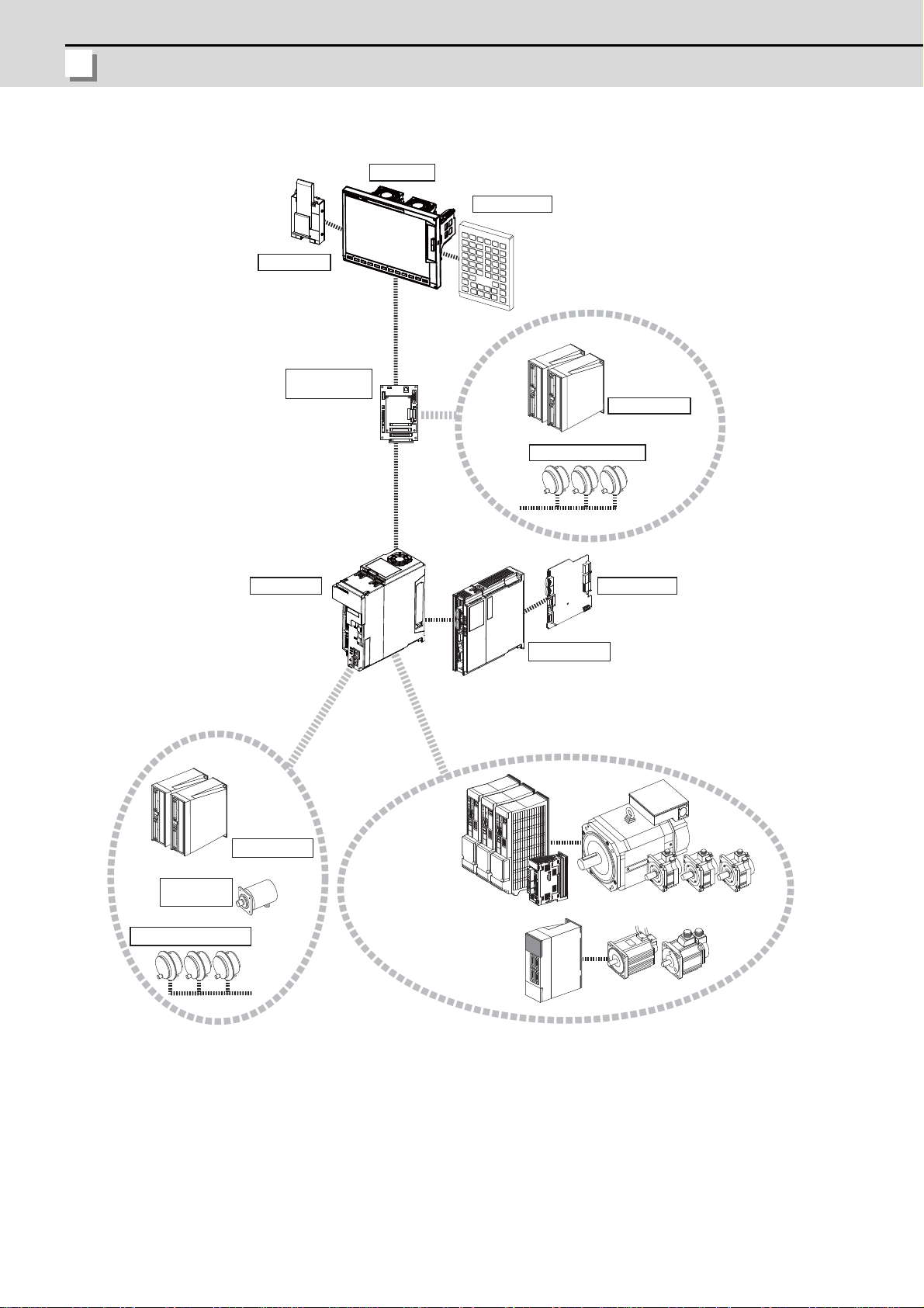
1.1 Device Configuration
Motor group
Auxiliary axis
Servo/Spindle
drive unit
MR-J2-CT/CT4 Series
Auxiliary axis Servo
drive unit
Manual pulse generator
Manual pulse penerator
Expansion unit
Control unit
Display unit
Keyboard unit
Remote I/O unit
Synchronous
feed encoder
Remote I/O unit
Operation panel
I/O unit
MDS-D/DH/DM Series
MDS-D-SVJ3/SPJ3 Series
Expansion card
Hard disk unit
2
Page 17
M700VW Series Setup Manual
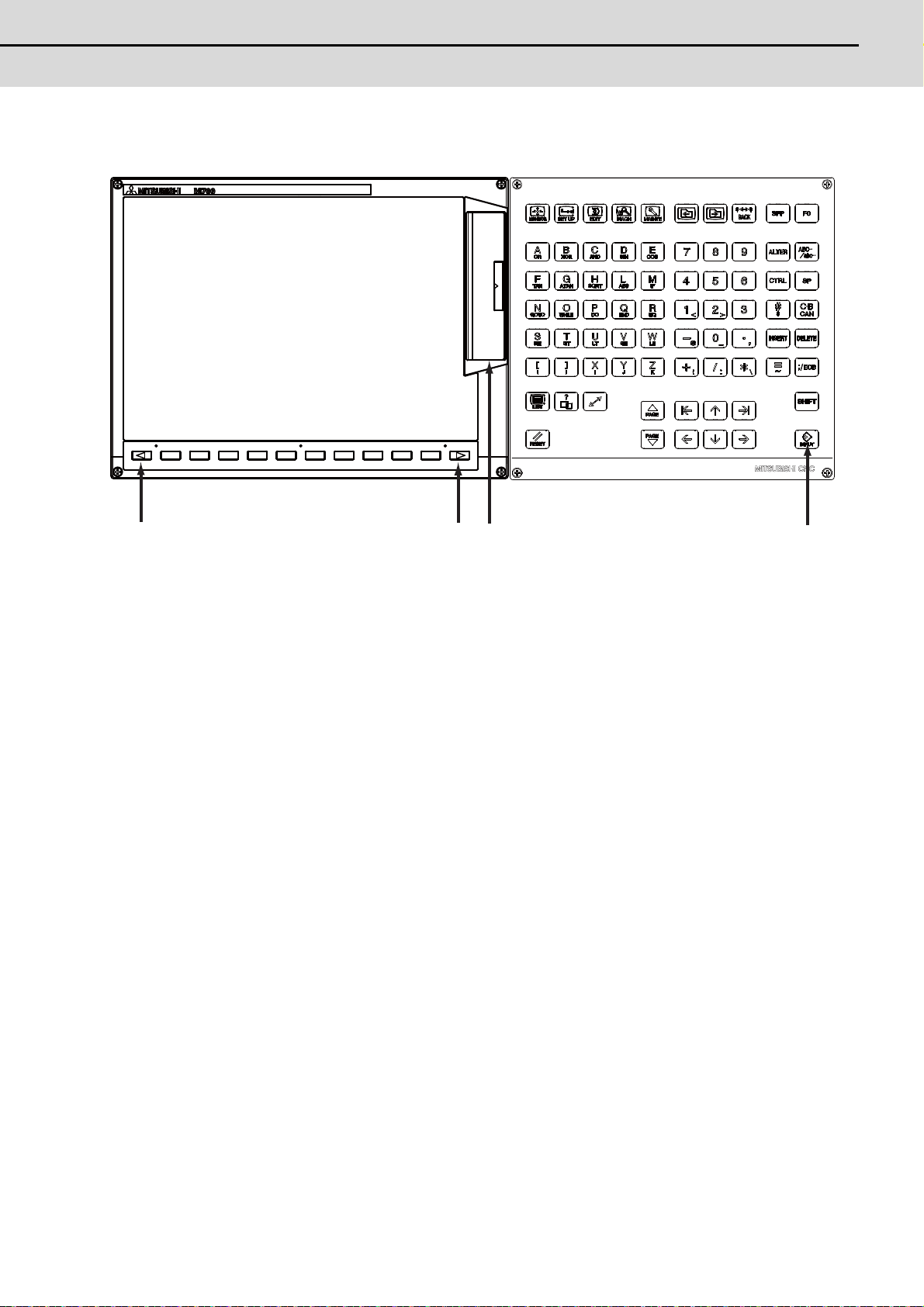
1.2 Hardware Configuration
1.2 Hardware Configuration
(A)
(B) (C)
(D)
The following shows the hardware names used in this manual.
(A) Cancel key
(B) Menu changeover key
(C) Memory card interface on front of display unit
(D) INPUT key
3
Page 18
1 Setup Outline
MITSUBISHI CNC
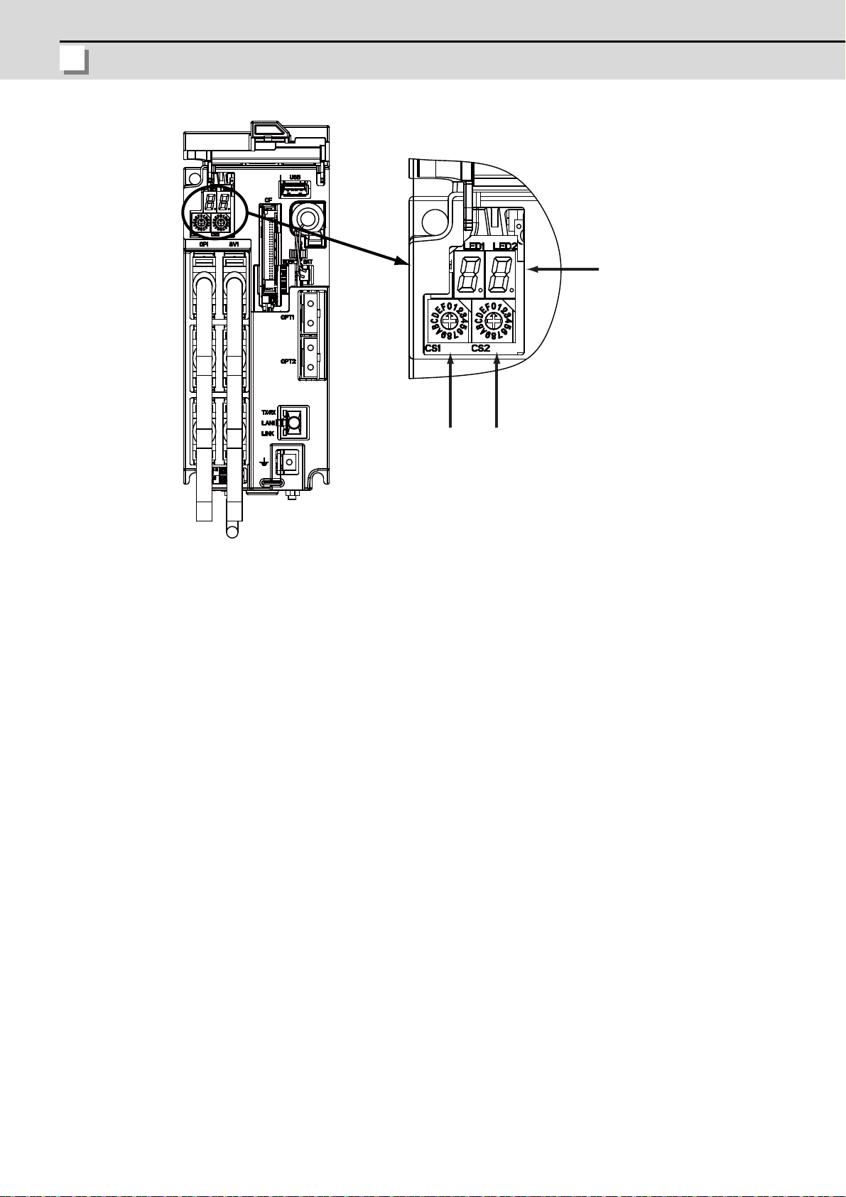
(A) Rotary switch 1
(A)
(B)
(C)
(B) Rotary switch 2
(C) 7-segment LED
4
Page 19
M700VW Series Setup Manual
1.3 Flow of Initial Setup
1.3 Flow of Initial Setup
WARNING
Refer to section 2
Refer to section 3
Refer to section 4
Refer to section 5
Refer to section 6
Refer to section 7
Refer to section 9
Refer to the Instruction Manual
Refer to section 8
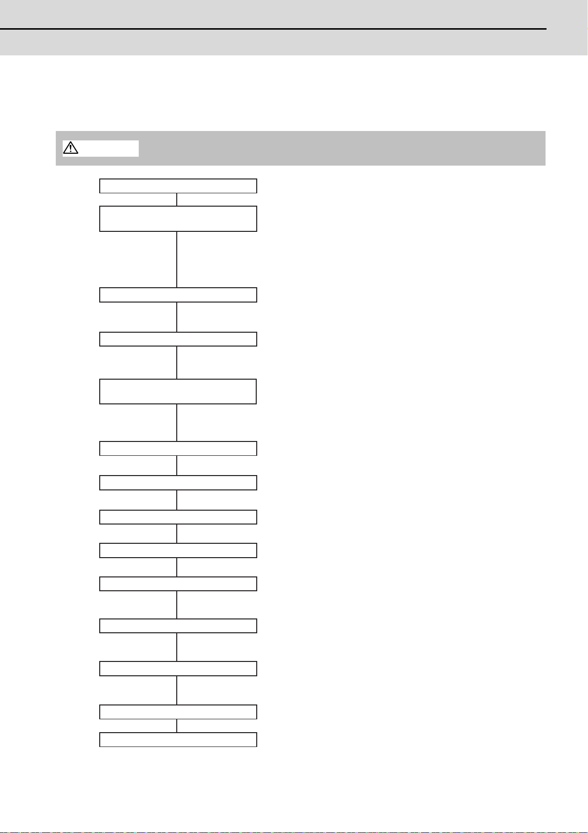
Points
Is the power supply within a specified range?
Is the power supply polarity correct?
Is the connection of the motor power cable and the detector cable correct?
Is the grounding correct?
Carry out the connecting and setting of drive units, batteries and remote I/O units.
Initialize the NC Internal data (SRAM).
Set the parameters on the system setup screen and the parameter screen.
Set the date and time on the integrated time screen.
Write the created PLC program to NC's ROM using GX Developer.
Confirm input/output of signals, alarm display and manual operation.
Carry out the setting for establishing the reference position (zero point).
Set the tool entry prohibited range.
Confirm that the spindle operates properly in manual/MDI operation.
Confirm the spindle rotation speed as well.
Start
Confirming the connection between
control unit and peripheral devices
Connecting and Setting the Hardware
Setting the Parameters and Date/Time
PLC Program Writing
Confirming the Basic Operation
Setting the Position Detection System
Setting the Stored Stroke Limit
Confirming the Spindle Operation
Inputting the machining program
End
Setting Up with
HMI Integrated Installer
Refer to section 10
Refer to section 11
Input the customized data for the handy terminal.
(Note) This procedure is required only when connecting the handy terminal.
Enable the credit system.
(Note) This procedure is required only when using the credit system.
Install and upgrade "Application of custom release"
with the HMI integrated installer.
If you do not need the installation, go to the next section.
Setting the Handy Terminal
Setting the Credit System
The following flow chart shows the procedures of the initial setup.
(Note) When setting up with backup files, refer to the section of "Data Backup and Restoration".
Do not cancel the emergency stop before confirming the basic operation.
5
Page 20

1 Setup Outline
MITSUBISHI CNC
For other settings, refer to the following sections:
- Setting the Deceleration Check
- Operating the Auxiliary Axis
- Data Backup and Restoration
6
Page 21

7
2
Connecting and Setting
the Hardware
Page 22
2 Connecting and Setting the Hardware
MITSUBISHI CNC
2.1 Connecting and Setting the Drive Unit
2.1.1 Connecting with Servo Drive Unit
Connect the optical communication cables from the NC to the each drive unit so that they run in a straight
line from the NC to the drive unit that is a final axis. Up to 16 axes can be connected per system. Note that
the number of connected axes is limited by the NC.
(Note) Refer to "Precautions for Using Optical Communication Cable" when handling an d wiring
optical communication cable.
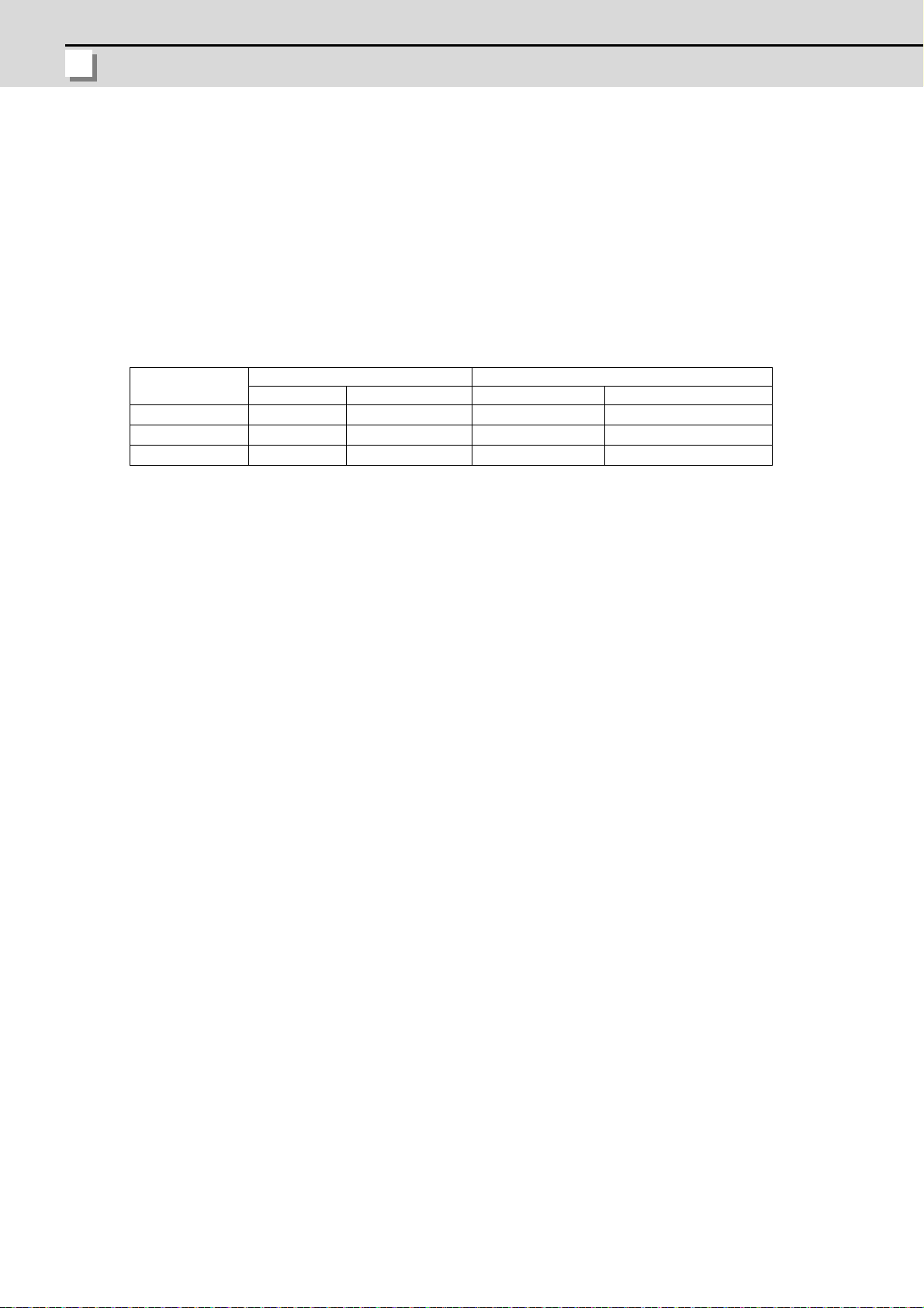
Cable application table
Cable
G396
G395
G380
Panel internal wiring Panel external wiring
Under 10m 10 to 30m 10m or less 10 to 30m
○× × ×
○× ○ ×
○○ ○ ○
(Note) Wiring of over 30m can be applied when relaying the optical signal by Optical Repeater
module. Refer to the specification manual of the drive unit for the details of the Optical
Repeater module.
8
Page 23
M700VW Series Setup Manual
2.1 Connecting and Setting the Drive Unit
2.1.1.1 Connecting with MDS-D/DH Series
CAUTION
POINT
Refer to the
instruction manual
of each NC for
details.
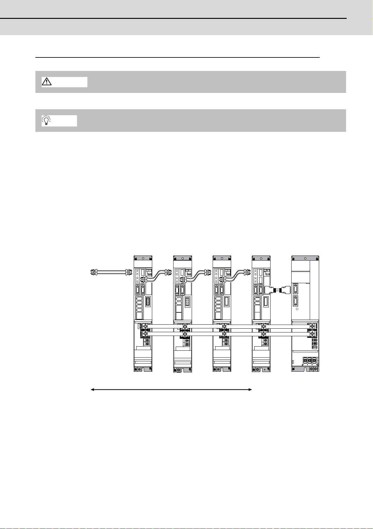
MDS-D/DH-V2
1st/2nd axis
MDS-D/DH-V2
3rd axis
MDS-D/DH-SP
6th axis
(Final axis)
MDS-D/DH-CVMDS-D-SP2
4th/5th axis
Connect the NC and the drive units by the optical communication cables. The distance between the
NC and the final drive unit must be within 30m and the bending radius within 80mm.
Axis Nos. are determined by the rotary switch for setting the axis No. (Refer to the MDS-D/DH Series
Instruction Manual.) The axis No. has no relation to the order for connecting to the NC.
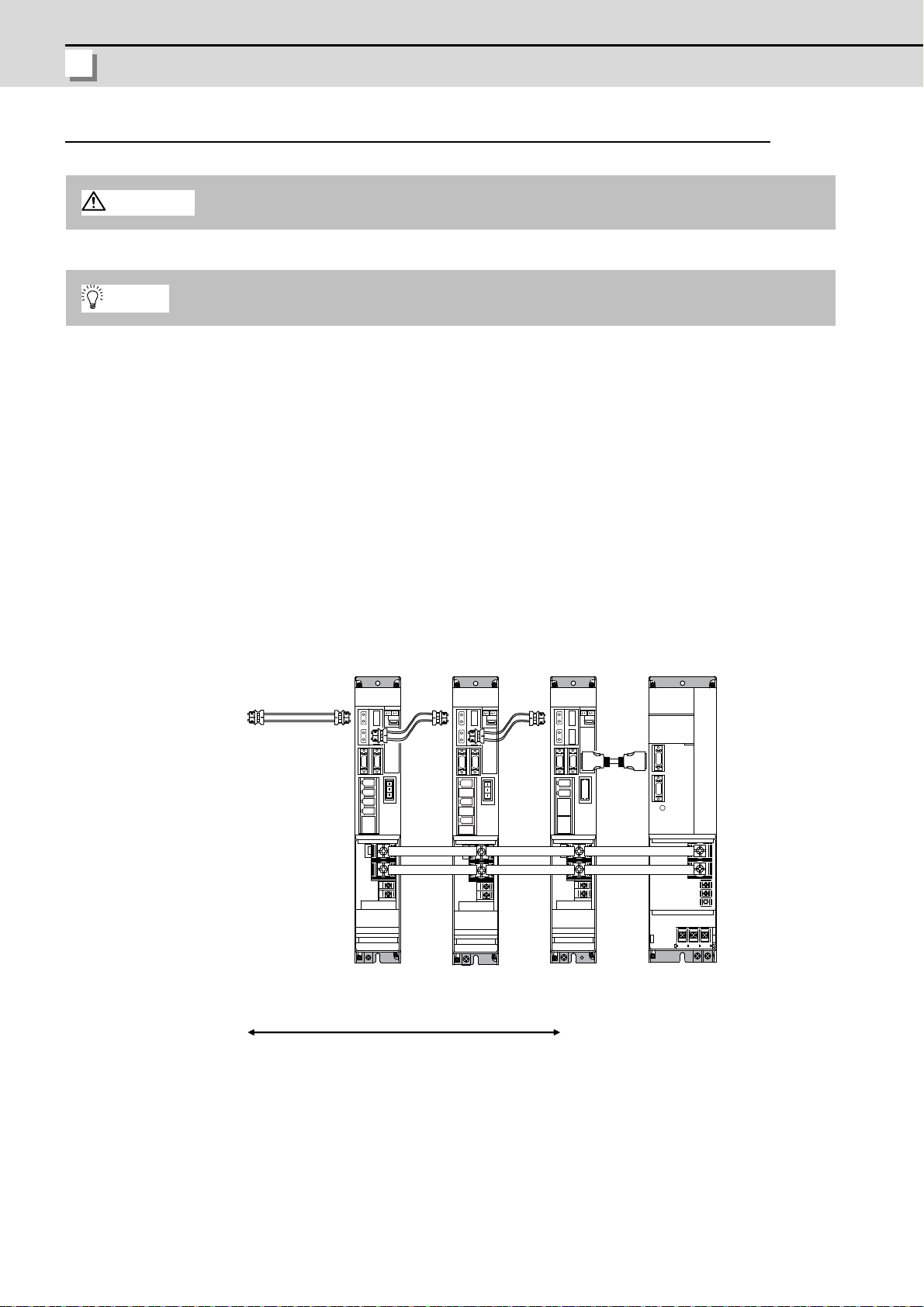
(1) When using one power supply unit
Connect the largest-capacity spindle drive unit to the final axis of the NC communication bus in order to
control the power supply unit. The spindle drive unit must be insta lled adjacent to the power supp ly unit.
In the system with servo only, a servo drive unit for controlling unbalance axis must be installed in the
same manner in the same way.
<Connection>
CN1A: CN1B connector on NC or previous stage's drive unit
CN1B: CN1A connector on next stage's drive unit
CN4: Connector for communication between power supply unit (master side) and drive unit
Connected
to the NC
Optical
communication
cable
CN4
CN4
The optical communication cables from the NC to the
final drive unit must be within 30m.
Connection when using one power supply unit
9
Page 24
2 Connecting and Setting the Hardware
MITSUBISHI CNC
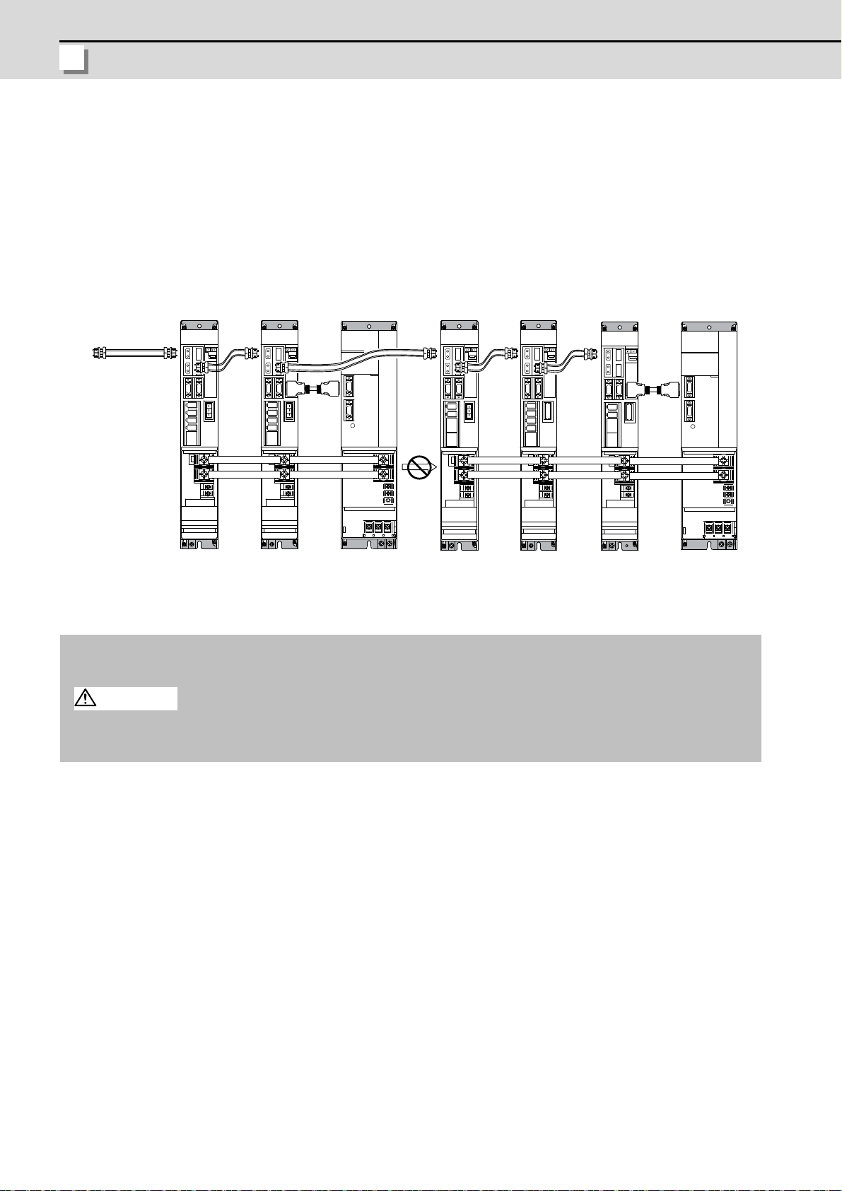
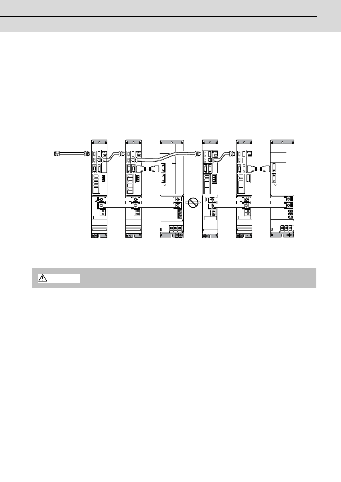
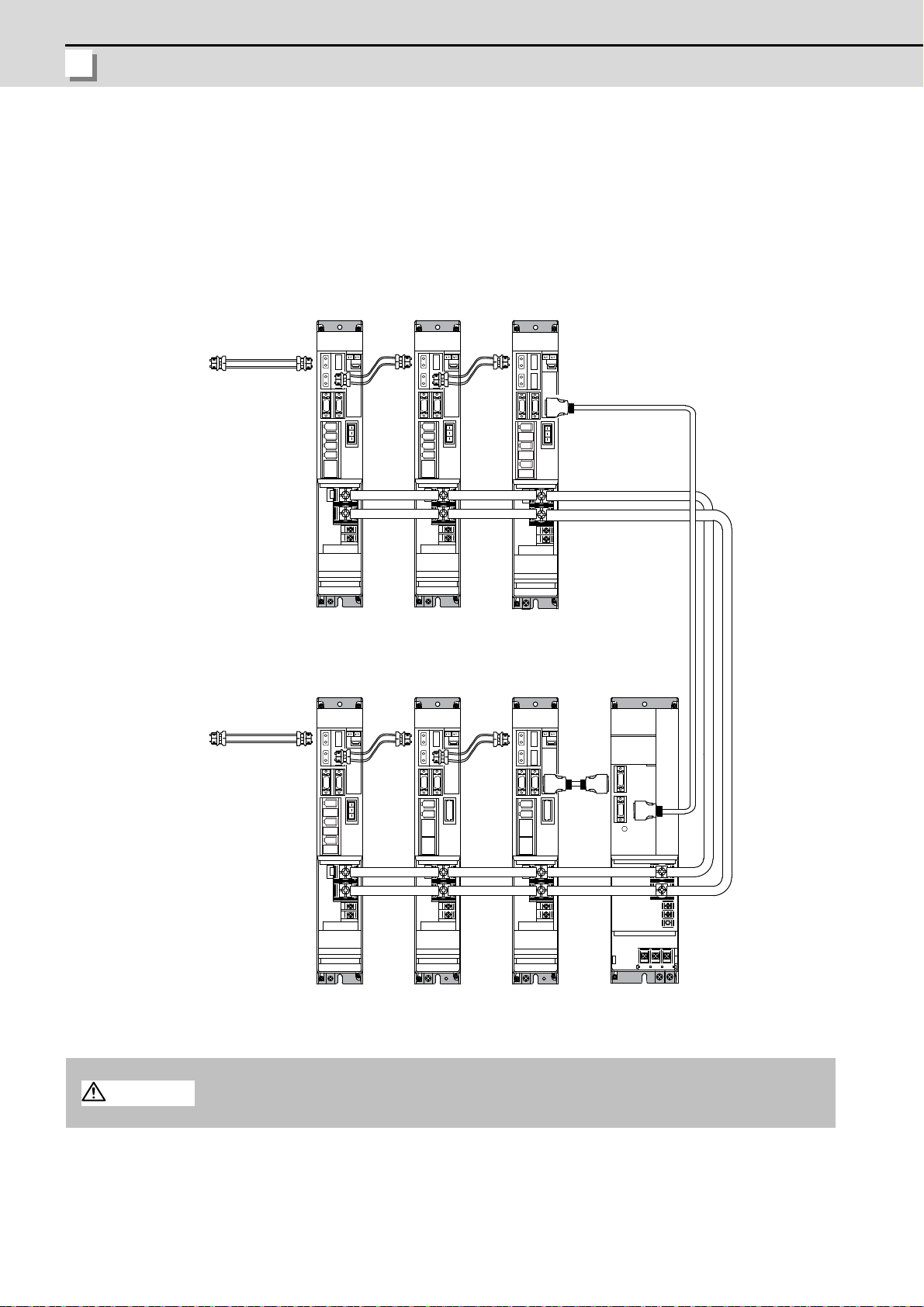
(2) When using two or more power supply units within a single NC communication bus system
Connected to the NC
MDS-D/DH-SP
8thaxis
(CV control axis)
MDS-D/DH-CV
[2]
MDS-D-SP2
6th/7th axis
MDS-D/DH-V2
1st/2nd axis
MDS-D/DH-V2
3rd/4th axis
(CV control axis)
MDS-D/DH-CV
[1]
MDS-D/DH-V1
5th axis
CAUTION
Two or more power supply units may be required within a single NC communication bus system if the
spindle drive unit capacity is large. The drive unit receiving power (L+, L-) from each power supp ly unit
must always have NC communication cable connection at the NC sid e of each pow er supply unit. In the
NC communication bus connection example below, power supply [1] cannot supply power ( L+, L-) to the
5th axis servo drive unit.
For basic connection information, refer to the MDS-D/DH Series Instruction Manual.
Optical
communication
cable
CN4
CN4
Power
cannot be
supplied
CN4
CN4
Connections when using two or more power supply units within a single NC communication bus system
1. The drive unit receiving power (L+, L-) from each power supply unit must always have NC
communication bus connection at the NC side of each power supply unit.
2. If two or more power supply units are connected in the drive system, confirm that the units are not
connected with each other through the L+ and L- lines before turning ON the power. Also make
sure that the total capacity of the drive units connected to the same power supply unit meets the
unit's selected capacity.
10
Page 25
M700VW Series Setup Manual
2.1 Connecting and Setting the Drive Unit
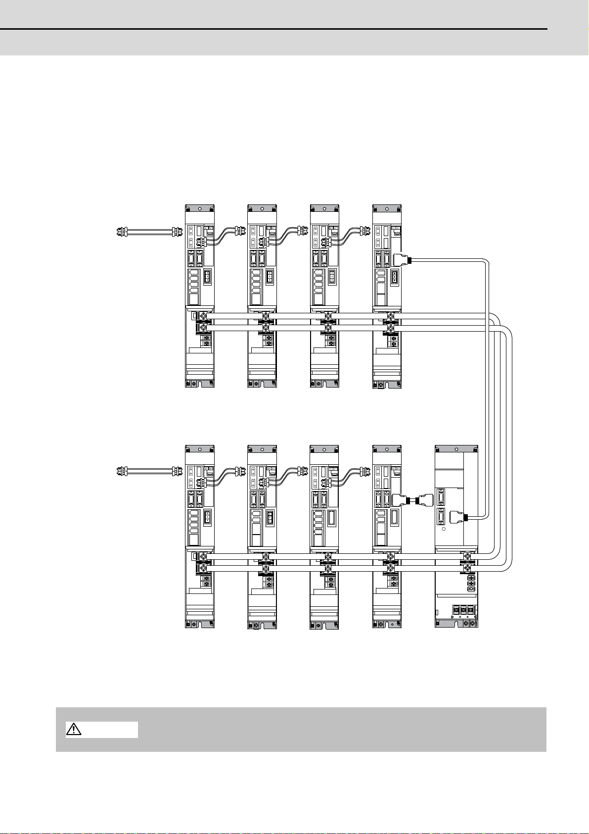
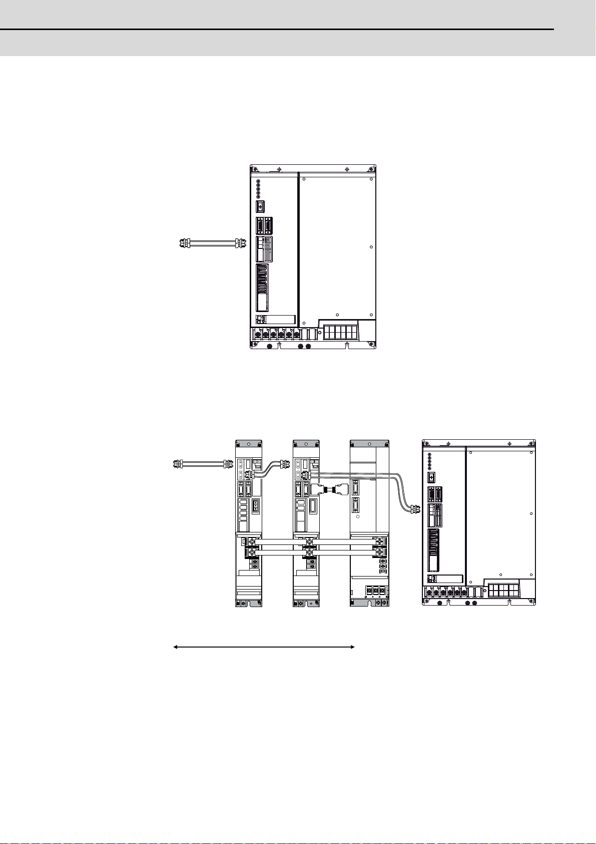
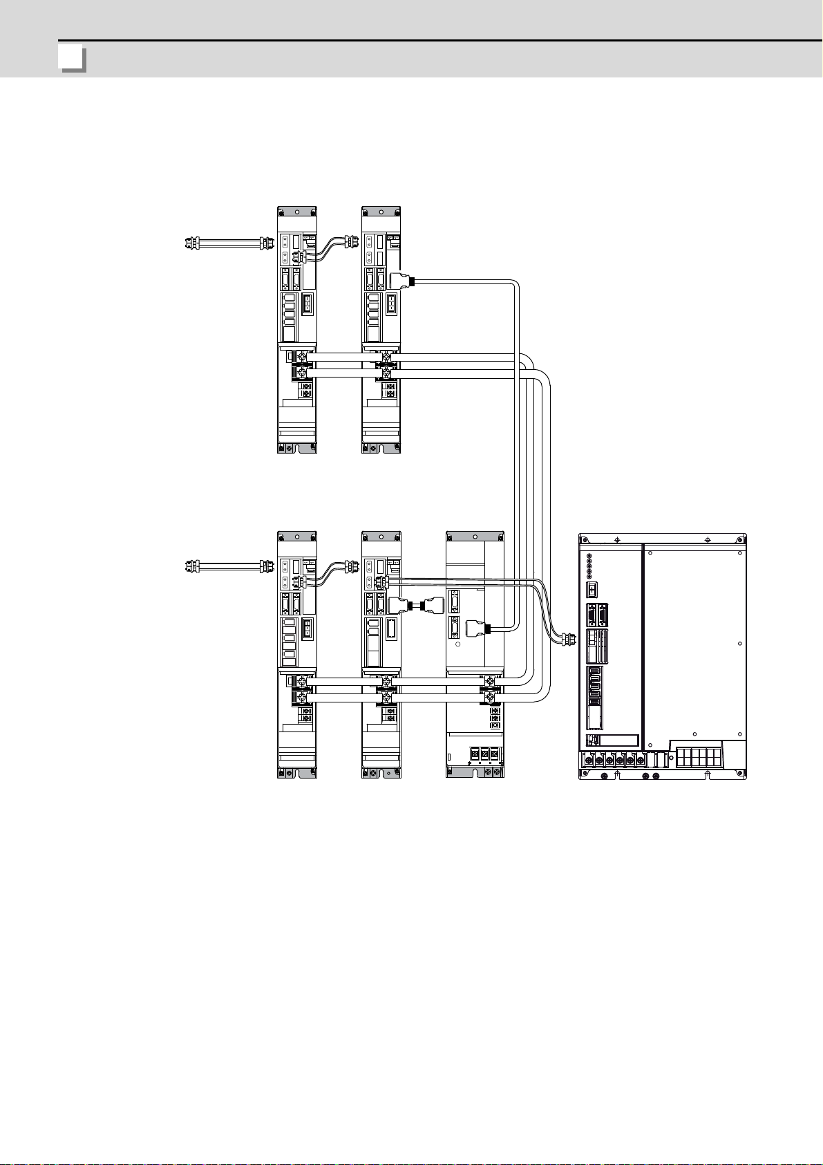
(3) When using one power supply shared unit by two NC communication bus systems
(
(
)
CAUTION
In systems employing a number of small-capacity drive units, a single power supply unit can be shared
by two NC communication bus systems. In this case, a power supply control axis must be set for each
axis of each NC communication bus.
For basic connection information, refer to the MDS-D/DH Series Instruction Manual.
Connected to the NC
(1st part system)
Optical
communication
cable
Connected to the NC
2nd part system
MDS-D/DH-V2
1st/2nd axis
MDS-D/DH-V2
8th/9th axis
MDS- D/DH -V2
3rd/4th axis
MDS-D/DH-V1
10th axis
MDS-D/DH-V2
5th/6th axis
MDS-D-SP2
11th/12th axis
MDS-D/DH-V1
7th axis
(CV control axis)
CN4
MDS-D/DH-SP
13th axis
CV control axis)
MDS-D/DH-CV
(Shared)
Optical
communication
cable
CN4
CN4
CN9
Connections when using one power supply shared by two NC communication bus systems
If the two NC communication bus systems include a spindle drive unit, connect the power supply
unit's CN4 connector to the CN4 connector of the largest capacity spindle drive unit. If there is no
spindle drive unit, connect to the unbalance-axis servo drive unit.
11
Page 26
2 Connecting and Setting the Hardware
MITSUBISHI CNC
2.1.1.2 Connecting with MDS-DM Series
CAUTION
POINT
Connect the NC and the drive units by the optical communication cables. The distance between the
NC and the final drive unit must be within 30m and the bending radius within 80mm.
Axis Nos. are determined by the rotary switch for setting the axis No. (Refer to the MDS-DM Series
Instruction Manual.) The axis No. has no relation to the order for connecting to the NC.
(1) Connecting the MDS-DM-V3
(a) When using one power supply unit
Connect the largest-capacity spindle drive unit to the final axis of the NC communication bus in
order to control the power supply unit. The spindle drive unit must be installed adjacent to the
power supply unit. In the system with servo only, a servo drive unit for controlling unbalance axis
must be installed in the same manner in the same way.
<Connection>
CN1A: CN1B connector on NC or previous stage's drive unit
CN1B: CN1A connector on next stage's drive unit
CN4: Connector for communication between power supply unit (master side) and drive unit
Connected
to the NC
Optical
communication
cable
MDS-D-V2
1st/2nd axis
MDS-DM-V3
3rd/4th/5th axis
MDS-D-SP
6th axis
(Final axis)
CN4
MDS-D-CV
CN4
12
The optical communication cables from the NC to the
final drive unit must be within 30m.
Connection when using one power supply unit
Page 27
M700VW Series Setup Manual
2.1 Connecting and Setting the Drive Unit
(b) When using two or more power supply units within a single NC communication bus system
7th axis
(CV control axis)
6th axis
1st/2nd axis
(CV control axis)
3rd/4th/5th axis
[2][1]
MDS-DM-V3
MDS-D-V2
MDS-D-CV MDS-D-V1 MDS-D-SP
MDS-D-CV
Power
cannot be
supplied
CAUTION
Two or more power supply units may be required within a single NC communication bus system if
the spindle drive unit capacity is large. The drive unit receiving power (L+, L-) from each power
supply unit must always have NC communication cable connection at the NC side of each power
supply unit. In the NC communication bus connection example below, power supply [1] cannot
supply power (L+, L-) to the 6th axis servo drive unit.
For basic connection information, refer to the MDS-DM Series Instruction Manual.
Connected to the NC
Optical
communication
cable
CN4
CN4
CN4
CN4
Connections when using two or more power supply units within a single NC communication bus system
The drive unit receiving power (L+, L-) from each power supply unit must always have NC
communication bus connection at the NC side of each power supply unit.
13
Page 28
2 Connecting and Setting the Hardware
MITSUBISHI CNC
(c) When using one power supply shared unit by two NC communication bus systems
5th/6th/7th axis
(CV control axis)
1st/2nd axis th axis3rd/4
Connected to the NC
(1st part system)
12th axis
(CV control axis)
(Shared)11th axis
8th/9th/10th axis
Connected to the NC
(2nd part system)
communication
Optical
cable
MDS-DM-V3
MDS-DM-V3
MDS-D-V2 MDS-D-V2
MDS-D-SP
MDS-D-SP MDS-D-CV
CAUTION
In systems employing a number of small-capacity drive units, a single power supply unit can be
shared by two NC communication bus systems. In this case, a power supply control axis must be
set for each axis of each NC communication bus.
For basic connection information, refer to the MDS-DM Series Instruction Manual.
Optical
communication
cable
CN4
Connections when using one power supply shared by two NC communication bus systems
CN4
CN4
CN9
14
If the two NC communication bus systems include a spindle drive unit, connect the power supply
unit's CN4 connector to the CN4 connector of the largest capacity spindle drive unit. If there is no
spindle drive unit, connect to the unbalance-axis servo drive unit.
Page 29
M700VW Series Setup Manual
2.1 Connecting and Setting the Drive Unit
(2) Connecting the MDS-DM-SPV2/SPV3
Spindle:1st axis
Servo:2nd/3rd/4th axis
to the NC
Connected
communication
Optical
cable
MDS-DM-SPV3
(a) When using only MDS-DM-SPV3
(b) When using the MDS-D unit together
Connected
to the NC
MDS-D-SP
(Final axis)
CN4
CN4
MDS-D-V2
5th/6th axis 7th axis
Optical
communication
cable
The optical communicationcables from the NC to the
final drive unit must be within 30m.
MDS-D-CV
MDS-DM-SPV3
Spindle:1st axis
Servo:2nd/3rd/4th axis
15
Page 30
2 Connecting and Setting the Hardware
MITSUBISHI CNC
(c) When using one power supply shared unit by two NC communication bus systems
(
)
Connected to the NC
(1st part system)
Optical
communication
cable
Connected to the NC
2nd part system
MDS-D-V2
5th/6th axis
MDS-DM-V3
9th/10th/11th axis
MDS-D-V2
7th/8th axis
(CV control axis)
12th axis
(CV control axis)
CN4
MDS-D-CVMDS-D-SP
(Shared)
MDS-DM-SPV3
Spindle:1st axis
Servo:2nd/3rd/4th axis
Optical
communication
cable
CN4
CN4
CN9
16
Page 31

M700VW Series Setup Manual
2.1 Connecting and Setting the Drive Unit
2.1.1.3 Connecting with MDS-SVJ3/SPJ3 Series
CAUTION
POINT
Connected
to the NC
Optical
communication
cable
MDS-D-SVJ3
1st axis
MDS-D-SVJ3
2nd axis
MDS-D-SVJ3
3rd axis
MDS-D-SPJ3
4th axis
The optical communication cable up to 5m can be used in G396 series, and up to 20m in G380 series.
Connect the NC and the drive units by the optical communication cables. The bending radius must be
within 50mm.
Axis Nos. are determined by the rotary switch for setting the axis No. (Refer to the MDS-SVJ3/SPJ3
Series Instruction Manual.) The axis No. has no relation to the order for connecting to the NC.
<Connection>
CN1A: CN1B connector on NC or previous stage's drive unit
CN1B: CN1A connector on next stage's drive unit
17
Page 32

2 Connecting and Setting the Hardware
MITSUBISHI CNC
2.1.2 Setting up without Connecting to the Motor/ Drive unit
When connecting the motor or drive unit after setting up the system, set the axis data beforehand to enable
the operation without the motor or drive unit. The following shows the procedures.
Setting up without Connecting to the Motor
The axis detach function can be used for servo axis. The detach function cannot be used for spindle.
(1) Set the drive unit rotary switch and "#1021 mcp_no" for the axis that is not connected to the motor.
(2) Set "1" to the parameter "#1070 axoff" for the axis that is not connected to the motor.
(3) Do (a) or (b).
(a) Set "1" to parameter "#8201 AX. RELEASE" for the axis that is not connected to the motor.
(b) Turn ON the control axis detach signal (Y780) for the axis that is not connected to the motor.
Setting up without Connecting to the Drive unit
Set the following parameters.
(1) Set "#1021 mcp_no" (for the servo axis) or "#3031 smcp_n o" (for the spindle axis) to th e axis that is no t
connected to the drive unit.
(2) Set the following parameters to the axis that is not connected to the drive unit.
For the servo axis: Set "1" to "#2018 no_srv".
For the spindle axis: Set "0" to "#3024 sout".
After connecting to the drive unit, make sure to set "#2018 no_srv" to "0" and "#3024 sout" to "1".
18
Page 33

M700VW Series Setup Manual
2.2 Setting the Rotary and DIP Switches
2.2 Setting the Rotary and DIP Switches
L axis
M axis
1-axis
Servo drive unit
(MDS-D/DH -V1)
1-axis
spindle drive unit
(MDS-D/DH-SP)
2-axis
spindle drive unit
(MDS-D-SP2)
2.2.1 MDS-D/DH Series
(1) Setting the rotary switch
Set the axis number with the rotary switch.
2-axis
Servo drive unit
(MDS-D/DH -V2)
#
$
%
&
'
(
#
$
%
&
'
(
#
$
%
&
'
(
MDS-D/DH-V1/V2/SP/SP2 setting
Rotary switch setting Axis No.
01st axis
1 2nd axis
23rd axis
34th axis
45th axis
56th axis
67th axis
78th axis
89th axis
9 10th axis
A 11th axis
B 12th axis
C 13th axis
D 14th axis
E 15th axis
F 16th axis
$
%
&
#
'
(
Power supply un it
(MDS-D/DH -CV)
#
$
%
&
'
(
#
$
%
&
'
(
$
%
&
#
'
(
MDS-D/DH-CV setting
When not using the external emergency stop: Set SW1 to "0"
When using the external emergency stop: Set SW1 to "4"
*Any other settings are prohibited.
19
Page 34

2 Connecting and Setting the Hardware
MITSUBISHI CNC
(2) Setting the DIP switch
(A) (B)
As a standard setting, turn the all DIP switches OFF.
The switches are OFF when facing bottom as illustrated.
Turning these switches ON sets the corresponding axis to the unused axis.
Carry out the unused axis setting when you use the multi-axes drive unit that has any unused axis.
(A) Used to set L axis to an unused axis
(B) Used to set M axis to an unused axis
20
Page 35

M700VW Series Setup Manual
2.2 Setting the Rotary and DIP Switches
2.2.2 MDS-DM Series
<MDS-DM-V3 Series>
(1) Rotary switch settings
Before turning on the power, the axis No. must be set with the rotary switch. The rotary switch settings
will be validated when the drive units are turned ON.
3-axis
Servo drive unit
(MDS-DM-V3)
L axis
8
79
6A
5B
4C
3D
2E
1F
0
M axis
8
79
6A
5B
4C
3D
2E
1F
0
Spindle drive unit
S axis
8
79
6A
5B
4C
3D
2E
1F
0
(MDS-D-SP
8
79
6A
5B
4C
3D
2E
1F
0
Rotary switch setting Axis No.
01st axis
1 2nd axis
23rd axis
34th axis
45th axis
56th axis
67th axis
78th axis
89th axis
9 10th axis
A 11th axis
B 12th axis
C 13th axis
D 14th axis
E 15th axis
F 16th axis
21
Page 36

2 Connecting and Setting the Hardware
MITSUBISHI CNC
(2) Setting the DIP switch
(A)(B) (C)
As a standard setting, turn the all DIP switches OFF.
The switches are OFF when facing bottom as illustrated.
Turning these switches ON sets the corresponding axis to the unused axis.
Carry out the unused axis setting when you use the multi-axes drive unit that has any unused axis.
(A) Used to set L axis to an unused axis
(B) Used to set M axis to an unused axis
(C) Used to set S axis to an unused axis.
<MDS-DM-SPV2/SPV3 Series>
The setting of the axis number is fixed as follows in the MDS-DM-SPV2/SPV3 Series.
Setting the MDS-DM-SPVx Details
1st axis Spindle axis
2nd axis L-axis
3rd axis M-axis
4th axis S-axis (Only MDS-DM-SPV3)
When using the MDS-DM-SPV2/SPV3, MDS-D and MDS-DM-V3 together, the axis numbers for the
MDS-DM-SPV2/SPV3 are fixed as above. Set the axis numbers from 4th axis or 5th axis.
22
Page 37

M700VW Series Setup Manual
2.2 Setting the Rotary and DIP Switches
2.2.3 MDS-D-SVJ3/SPJ3 Series
MDS-D-SVJ3 MDS-D-SPJ3
Set the axis number with the rotary switch.
8
79
6A
5B
4C
3D
2E
1F
0
Rotary switch setting Axis No.
01st axis
1 2nd axis
23rd axis
34th axis
45th axis
56th axis
67th axis
78th axis
89th axis
9 10th axis
A 11th axis
B 12th axis
C 13th axis
D 14th axis
E 15th axis
F 16th axis
4C
8
79
6A
5B
3D
2E
1F
0
23
Page 38

2 Connecting and Setting the Hardware
MITSUBISHI CNC
2.3 Connecting the Batteries
Front cover
Battery holder
Battery
Battery
connector
BAT connector
CAUTION
2.3.1 Control Unit Battery
The battery is not connected when the machine is delivered. Be sure to connect the battery before
starting up.
A lithium battery in the control unit battery holder retains parameter settings, machining programs and the
like, which requires to be backed up at the power OFF.
Battery Q6BAT
Battery cumulative data holding time
Battery life Approx. 5 years (from date of battery manufacture)
[Installation method]
(1) Check that the machine power is turned OFF. (If the power is not OFF, turn it OFF.)
(2) Confirm that the control unit LED, 7-segment display, etc., are all OFF.
(3) Open the battery cover of the control unit. Pull the right side of the battery cover toward front.
(4) Fit the new battery into the battery holder.
(5) Insert the connector connected to the new battery into the BAT connector. Pay attention to the
connector orientation: do not insert backwards.
(6) Close the front cover of the control unit. At this time, confirm that the cover is closed by listening for
the "click" sound when the latch catches.
45,000 hours (At 0 to 45°C. The life will be shorter if the temperature is high.)
[Precautions for handling battery]
24
(1) Do not disassemble the battery .
(2) Do not place the battery in flames or water.
(3) Do not pressurize and deform the battery.
(4) This is a primary battery so do not charge it.
Do not short-circuit, charge, overheat, incinerate or disassemble the battery.
Page 39

M700VW Series Setup Manual
2.3 Connecting the Batteries
2.3.2 Servo Drive Unit Battery
BT1
Battery
To battery holder
Battery connector
Battery connector connection part magnified figure
Connector for
connecting cell battery
Connect the cell battery with BT1.
(Note) The battery connection is not necessary unless the drive unit employs absolute position detection.
(Spindle drive unit does not require the battery, because the unit does not employ ab solute position
detection.)
MDS-D/DH-V1/V2 and MDS-DM-V3
Connect the battery connector to the connector of the dr ive unit.
BTA
1 2 1
1 2
BTB
(Note) There are different types of battery. Refer to the drive unit's specification manual for details.
Type ER6V-C119B A6BAT(MR-BAT)
Installation
type
Hazard class Not applicable
Number of
connectable
Drive unit with battery holder
type
Up to 2 axes
Dedicated case type
Not applicable
(24 or less)
Up to 8 axes
(When using dedicated
axes
case)
MDS-A-BT- □□
Unit and battery integration
type
Class9
(excluding MDS-A-BT-2)
2 to 8 axes Up to 6 axes
Battery change Possible Possible Not possible Possible
(2)
(1)
Battery connector
Appearance
To the battery
holder
バッテリ
Battery
ER6V-C119B
Battery
A6BAT
(MR-BAT)
Dedicated case
MDS-BTCASE
(3)
FCU6-BTBOX-36
Unit and battery integration
type
Not applicable
(4)
25
Page 40

2 Connecting and Setting the Hardware
MITSUBISHI CNC
MDS-DM-SPV2/SPV3
BT1
Battery
To battery holder
Battery
connector
Battery connector connection part magnified figure
Connector for
connecting cell battery
Connect the cell battery with BT1.
BAT
Connect the battery connector to the connector of the drive unit.
BTA
12
12
MDS-D-SVJ3
Connect the battery connector to the connector BAT of the drive unit.
Remove
Install
26
Page 41

M700VW Series Setup Manual
2.4 Connecting and Setting the Remote I/O Unit
2.4 Connecting and Setting the Remote I/O Unit
(F)
DX10* DX11*/12* DX14*
A
2.4.1 Outline of the Remote I/O Unit
There are eight types of remote I/O unit (FCUA-DX***): DX10*, DX11*, DX12* and DX14* (* is "0" or "1").
Specifications are different as shown below. Each unit has one or two rotary switch(es) for unit No. setting,
which links the device Nos. (with X/Y).
Front
(H)
(A)
(A)
(E)
(A)
(B)
(C)
(D)
(B)
(C)
(D)
(A) Left input connector
(B) DIO specification switch
Currently not used. Always set to "OFF".
Front view View from A direction
OFF
(C),(F) Rotary switch
(D) Left output connector
(E) Right input connector
(G) Right output connector
(H) Analog input/output connector
(F)
(G)
(B)
(C)
(D)
27
Page 42

2 Connecting and Setting the Hardware
MITSUBISHI CNC
Bottom
(A)
(B)
(C)
(A) RIO1 (From controller)
(B) RIO2 (To terminating resister or to next RIO unit)
(C) DCIN (24VDC input)
Number of
occupied
stations
Unit type
DX10* (FCUA-DX10*)
DX11* (FCUA-DX11*)
DX12* (FCUA-DX12*)
DX14* (FCUA-DX14*)
Machine control signals that can be
handled
Digital input signal (DI) (Photocoupler
insulation)
Digital output signal (DO) (Non-insulated) 32 points - 32 points
Digital input signal (DI) (Photocoupler
insulation)
Digital output signal (DO) (Non-insulated) 32 points 16 points 48 points
Digital input signal (DI) (Photocoupler
insulation)
Digital output signal (DO) (Non-insulated) 32 points 16 points 48 points
Analog output (AO) - 1 point 1 point
Digital input signal (DI) (Photocoupler
insulation)
Digital output signal (DO) (Non-insulated) 32 points - 32 points
Analog input (AI) - 4 points 4 points
Analog output (AO) - 1 point 1 point
Left Right Total
32 points - 32 points
32 points 32 points 64 points
32 points 32 points 64 points
32 points - 32 points
(Note) "*" in the table is "0" when the output is sink type, and is "1" when the output is source type. The
input is changeable.
1
2
2
2
28
Page 43

M700VW Series Setup Manual
2.4 Connecting and Setting the Remote I/O Unit
2.4.2 Connection and Station No. Setting on Remote I/O Unit
㨪
㨪
RIO1
RIO2
FCUA-R211/SH41
FCUA-R211/SH41
FCU7-MU031/041
FCU7-MA041
FCUA-DX1**
FCUA-DX1**
Station No.1 - 8
Remote I/O unit
Control unit
Station No.1 - 8
Remote I/O 2ch
Max. 8 channels
Max. input: 256 points (X000 to X0FF)
Max. output: 256 points (Y000 to Y0FF)
Max. 8 channels
Max. input: 256 points (X100 to X1FF)
Max. output: 256 points (Y100 to Y1FF)
Remote I/O 1ch
When connecting directly to the control unit
(Note) A remote I/O unit has one or two rotary switch(es) for unit No. setting, which links the device
Nos. (with X/Y).The rotary switch setting is as follows, from "0" to "7".
Station
No.
10
21
32
43
54
65
76
87
Rotary switch
29
Page 44

2 Connecting and Setting the Hardware
MITSUBISHI CNC
When connecting to the operation panel I/O unit
㨪
㨪
FCU7-DX670/671
FCUA-R211/SH41
RIO3
RIO3
G018
OPI
FCUA-R211/SH41
G018
㨪
㨪
FCU7-DX770/771
FCU7-MU031/041, FCU7-MA041
Control unit
Operation panel I/O unit
Max. 5 stations
Max. input: 160 points (X200 to X2BF)
Max. output: 160 points (Y200 to Y2BF)
Max. 4 stations
Max. input: 128 points (X200 to X2BF)
Max. output: 128 points (Y200 to Y2BF)
Remote I/O unit
Input: 32 points (X200 to X2BF)
Output: 32 points (Y200 to Y2BF)
FCUA-DX1**
Input: 64 points (X200 to X2BF)
Output: 64 points (Y200 to Y2BF)
Set one station among
station No. 1 to 6
No. 7 and 8 are
occupied
Set two stations among
station No. 1 to 6
No. 7 and 8 are
occupied
Remote I/O 3ch
Remote I/O 3ch
Max. 5 stations
among No. 1 to 6
Max. 4 stations
among No. 1 to 6
0
1
F
2 E
D
3
4 C
B
5
6 A
7 9
8
0
1
F
D
B
8
0
1
F
2 E
3
4 C
5
6 A
7 9
2 E
D
3
4 C
B
5
6 A
7 9
8
(Note) Operation panel I/O unit occupies one or two stations among station No. 1 to 6. (Station No. 7
0
1
F
2 E
3
D
4 C
5
B
6 A
7 9
8
0
1
F
2 E
3
D
4 C
5
B
6 A
7 9
8
0
1
F
D
B
8
0
1
F
2 E
6 A
7 9
2 E
3
D
4 C
5
3
4 C
B
5
6 A
7 9
8
and 8 are reserved for manual pulse generator.)
Therefore, RIO3 can use five or four stations from No. 1 to 6.
30
Page 45

M700VW Series Setup Manual
2.4 Connecting and Setting the Remote I/O Unit
2.4.3 Station No. Setting when Using Multiple Remote I/O Units
0
㧗
FCUA-DX100/101
0
1
2
㧗
㧗
FCUA-DX100/101
FCUA-DX110/111
or
FCUA-DX120/121
Multiple remote I/O units can be used, as long as the total No. of occupied stations connected with serial
links is eight or less. (four/five or less when connected to the operation panel I/O unit).
Unit type Number of occupied stations
FCUA-DX10* 1
FCUA-DX11* 2
FCUA-DX12* 2
FCUA-DX14* 2
When using multiple remote I/O units, a characteristic station No. must be set for each unit. The FCUADX10* unit has one rotary switch, FCUA-DX11*, DX12* and DX14* unit have two. Each of these
switches must be set to a characteristic station No. within a range of 0 to 7 (0 to 5 when connected to
the operation panel I/O unit).
When connecting directly to the control unit
Setting example 1
Total number of occupied stations: 1
Setting example 2
Number of occupied stations: 1 2
Total number of occupied stations: 3
31
Page 46

2 Connecting and Setting the Hardware
MITSUBISHI CNC
Setting example 3
0 1
㧗 㧗 㧗
㧗
2 3
4 5
6 7
FCUA-DX110/111
or
FCUA-DX120/121
Number of occupied stations: 2 2 2 2
Total number of occupied stations: 8 (Maximum configuration)
32
Page 47

M700VW Series Setup Manual
2.4 Connecting and Setting the Remote I/O Unit
When connecting to the operation panel I/O unit
㧗
FCUA-DX100/101
1
FCU7-DX670/671
4
5
2
3
FCU7-DX670/671
㧗
㧗
FCUA-DX110/111
or
FCUA-DX120/121
FCUA-DX110/111
or
FCUA-DX120/121
㧗
FCUA-DX100/101
1
Operation panel I/O unit occupies one or two stations among station No. 1 to 6. (Station No. 7 and 8 are
reserved for manual pulse generator.)
Therefore, RIO3 can occupy up to five or four stations, as shown below.
Operation panel I/O unit
type
Max. number of stations
(RIO3 connection)
Max. number of I/O
points (RIO3
connection)
Remote I/O
Rotary switch
Setting range
FCU7-DX670/671 5 channels 160 points/160 points 0 to 5
FCU7-DX770/771 4 channels 128 points/128 points 0 to 5
Setting example 1
0
1
0
1
F
2 E
3
D
4 C
5
B
6 A
7 9
8
F
2 E
D
3
4 C
B
5
6 A
7 9
8
Number of occupied stations: 1
Total number of occupied stations: 1
Setting example 2
0
1
0
1
F
2 E
3
D
4 C
5
B
6 A
7 9
8
F
2 E
D
3
4 C
B
5
6 A
7 9
8
Number of occupied stations: 1 2 2
Total number of occupied stations: 5 (Maximum configuration)
33
Page 48

2 Connecting and Setting the Hardware
MITSUBISHI CNC
Setting example 3
㧗
4
5
FCU7-DX770/771
FCUA-DX110/111
or
FCUA-DX120/121
㧗
FCUA-DX110/111
or
FCUA-DX120/121
2
3
0
1
0
1
F
2 E
3
D
4 C
5
B
6 A
7 9
8
0
1
F
2 E
3
D
4 C
5
B
6 A
7 9
8
F
2 E
3
D
4 C
5
B
6 A
7 9
8
0
1
F
2 E
D
3
4 C
B
5
6 A
7 9
8
Number of occupied stations: 2 2
Total number of occupied stations: 4 (Maximum configuration)
34
Page 49

M700VW Series Setup Manual
2.4 Connecting and Setting the Remote I/O Unit
2.4.4 Device No. Assignment
The devices used by the PLC are determined as follows after the station Nos. are set with the rotary
switches.
Rotary switch No.
0 X00 to X1F Y00 to Y1F(Y0F)
1 X20 to X3F Y20 to Y3F(Y2F)
2 X40 to X5F Y40 to Y5F(Y4F)
3 X60 to X7F Y60 to Y7F(Y6F)
4 X80 to X9F Y80 to Y9F(Y8F)
5 XA0 to XBF YA0 to YBF(YAF)
6 XC0 to XDF YC0 to YDF(YCF)
7 XE0 to XFF YE0 to YFF(YEF)
Rotary switch No.
0 X100 to X11F Y100 to Y11F(Y10F)
1 X120 to X13F Y120 to Y13F(Y12F)
2 X140 to X15F Y140 to Y15F(Y14F)
3 X160 to X17F Y160 to Y17F(Y16F)
4 X180 to X19F Y180 to Y19F(Y18F)
5 X1A0 to X1BF Y1A0 to Y1BF(Y1AF)
6 X1C0 to X1DF Y1C0 to Y1DF(Y1CF)
7 X1E0 to X1FF Y1E0 to Y1FF(Y1EF)
Device No. read in Output device No. Analog output (AO)
RIO channel 1 RIO channel 1 RIO channel 1
The rotary switches
correspond to the file
registers R200 to R207 in
order of small numbers.
Device No. read in Output device No. Analog output (AO)
RIO channel 2 RIO channel 2 RIO channel 2
The rotary switches
correspond to the file
registers R200 to R207 in
order of small numbers.
Rotary switch No.
0 X200 to X21F Y200 to Y21F(Y20F)
1 X220 to X23F Y220 to Y23F(Y22F)
2 X240 to X25F Y240 to Y25F(Y24F)
3 X260 to X27F Y260 to Y27F(Y26F)
4 X280 to X29F Y280 to Y29F(Y28F)
5 X2A0 to X2BF Y2A0 to Y2BF(Y2AF)
6-7--
Device No. read in Output device No. Analog output (AO)
RIO channel 3 RIO channel 3 RIO channel 3
The rotary switches
correspond to the file
registers R200 to R205 in
order of small numbers.
The values shown in parentheses are the device range of the card mounted to the right side of the unit.
(Note) When the analog output is equipped to several RIO channels, maximum of four RIO channels will
be valid in the following order of priority.
(1) RIO channel 1, (2) RIO channel 2, (3) RIO channel 3
35
Page 50

2 Connecting and Setting the Hardware
MITSUBISHI CNC
2.5 Initializing the NC Internal Data (SRAM)
A
A
A
A
The initialization does not affect the settings of the option parameters.
(1) With the NC power OFF, turn the left rotary switch (CS1) to "0" and the right rotary switch (CS2) to "C".
Then, turn the power ON.
LED1 LED2
0
1
F
D
B
2 E
3
4 C
5
6
7 9
8
CS1 CS2
0
1
F
D
B
2 E
3
4 C
5
6
7 9
8
(2) The LED display will change to "08." -> "00" -> "01" -> ... "08". The process is completed when "0Y" is
displayed.
LED1 LED2
(3) Turn the NC power OFF.
(4) Set the right rotary switch (CS2) to "0".
D
B
LED1 LED2
0
1
F
7 9
8
0
1
F
2 E
D
3
4 C
B
5
6
2 E
3
4 C
5
6
7 9
8
CS1 CS2
(5) Turn the power ON again.
36
Page 51

M700VW Series Setup Manual
2.5 Initializing the NC Internal Data (SRAM)
(Note 1) After the initializing and the NC power ON, the IP address is initialized as follows.
<Base specification parameter>
#1934 Local IP address: 192.168.100. 1
Failure to communicate with the screen may be caused by inconsistency between the parameter
value and the "C:\WINDOWS\melcfg.ini" setting value. Confirm that "C:\WINDOWS\melcfg.ini" is
set as shown below.
Last line of C:\WINDOWS\melcfg.ini
...
[HOSTS]
TCP1=192.168.100.1,683
(Note 2) The initial screen after the initialization is displayed in English. Refer to "Setting on the System
Setup Screen" for how to set a language to display.
37
Page 52

2 Connecting and Setting the Hardware
MITSUBISHI CNC
38
Page 53

39
3
Setting the Parameters
and Date/Time
Page 54

3 Setting the Parameters and Date/Time
MITSUBISHI CNC
Confirm the emergency stop state before carrying out the steps in this chapter.
WARNING
3.1 Setting on the System Setup Screen
Set the following items on the system setup screen.
- Displayed language and the number of spindle connections
- Number of axes and command type for each part system
- Servo I/F connection channel and rotary switch setting for each spindle, as well as types of the
motor and the power supply connected to each spindle drive
- Servo I/F connection channel and rotary switch setting for each servo axis, as well as types of the
motor, encoder, and the power supply connected to each servo drive
(1) Enter the password on the Mainte screen.
(a) On the Mainte screen, select [Mainte] and then [Psswd input].
(b) Enter "MPARA" in the setting area and press the INPUT key.
(Note 1) To enter the character "A", press the shift key and then "A" key. Do not press both keys at the
same time.
(2) Select a displayed language.
(a) Press the cancel key to return to the Mainte screen. Select [Mainte] and then [System Setup].
(b) Set the No. of the language to display in "language displayed".
40
Page 55

M700VW Series Setup Manual
3.1 Setting on the System Setup Screen
(3) Carry out the spindle and servo axis settings. Set the following items.
Common setting
Number of spindles:
Set the number of spindles connected to the NC. This setting is registered at "#1039 spinno
(Number of spindles)".
Number of MR-J2-CT:
Set the number of auxiliary axes connected to the NC. This setting is registered at "#1044
auxno".
Setting by system
Number of axes:
Set the number of axes for each part system and PLC. This setting is registered at "#1002
axisno (Number of axes)".
(Note) A setting error occurs if a value "1" or higher is set for any of the 2nd to 4th part
systems while the setting for the previous part system is "0".
Command type:
Set the command type for each part system. This setting is registered at "#1037 cmdtyp
(Command type)".
(Note) Although this can be set individually for each part system, it will be shared by the
entire part system if specified for the machining center.
Setting by spindle area
Ch / Rotary SW No.:
Set the servo I/F connection channel and the rotary switch No. (2-digit value) for each spindle
drive unit. This setting is registered at "#3031 smcp_no (Drive unit I/F channel No. (spindle))".
1st digit: Servo I/F connection channel
2nd digit: Rotary switch No.
Motor type:
Set the motor types that are connected to each spindle. Input the values as indicated at the
guidance display area. The input values are not converted to motor types.
Power Supply type:
Set the power supply types that are connected to each spindle drive unit.
Input the values as indicated at the guidance display area. The input value s are then converted
to, and displayed as, power supply types. "0" means "No connection".
Setting by servo
Ch / Rotary SW No.:
Set the servo I/F connection channel and the rotary switch No. (2-digit value) for each servo
drive unit. This setting is registered at "#1021 mcp_no (Drive unit I/F channel No. (servo))".
1st digit: Servo I/F connection channel
2nd digit: Rotary switch No.
Motor type:
Set the motor types that are connected to each servo axis.
Input the values as indicated at the guidance display area. The input value s are then converted
to, and displayed as, motor types.
Detector type:
Set the encoder types that are connected to each servomotor.
Input the values as indicated at the guidance display area. The inp ut values are then converted
to, and displayed as, encoder types.
Power Supply type:
Set the power supply types that are connected to each servo drive unit.
Input the values as indicated at the guidance display area. The input value s are then converted
to, and displayed as, power supply types. "0" means "No connection".
41
Page 56

3 Setting the Parameters and Date/Time
MITSUBISHI CNC
Setting example (with three servo axes and a spindle)
X axis
Power supply unit
Y axis
Z axis
Spindle
42
Page 57

M700VW Series Setup Manual
3.1 Setting on the System Setup Screen
(5) Write the parameter settings and format the system.
(a) Select [Param setting].
(b) The message "Set up parameter? (Y/N)" appears. Press "Y".
(c) The message "Param set ended. Format NC memory? (Y/N)" appears. Press "Y".
(d) The message "Format complete" appears when the format is completed.
(6) Turn the power OFF and ON.
(Note) When MDS-D-SVJ3/SPJ3 Series is used, the regenerative resisto r type must be set with the servo
parameter "#2236 SV036" and the spindle parameter "#13032 SP032" in addition to the settings
above.
43
Page 58

3 Setting the Parameters and Date/Time
MITSUBISHI CNC
3.2 Setting the Parameters for the Machine Specifications
(1) On the Mainte screen, select [Mainte] and then [Psswd input]. Enter "MPARA" in the setting area and
press the INPUT key.
(Note 1) To enter the character "A", press the shift key and then "A" key. Do not press both keys at the
same time.
(2) Press the cancel key to return to the Mainte screen. Then select [Param].
Set the parameters according to the machine specifications. Setting of the following parameters is
necessary.
Base system parameters
"#1025 I_plane (Initial plane selection)"
"#1026 base_I (Base axis I)"
"#1027 base_J (Base axis J)"
"#1028 base_K (Base axis K)"
"#1029 aux_I (Flat axis I)"
"#1030 aux_J (Flat axisJ)"
"#1031 aux_K (Flat axis K)"
Base axis specification parameter
"#1013 axname (Axis name)"
Base common parameters
"#1038 plcsel (Ladder selection ... Set "0")"
"#1041 I_inch (Initial state (inch))"
"#1042 pcinch (PLC axis command (inch))"
"#1239 set11/bit1 (Handle I/F selection)"
"#1240 set12/bit0 (Handle input pulse)"
Axis specification parameter
"#2001 rapid (Rapid traverse rate)"
"#2002 clamp (Cutting feedrate for clamp function)"
"#2003 smgst (Acceleration and deceleration modes)"
"#2004 G0tL (G0 time constant)"
"#2007 G0tL (G1 time constant)"
Servo parameter
"#2201 SV001 (PC1 Motor side gear ratio)"
"#2202 SV002 (PC2 Machine side gear ratio)"
"#2218 SV018 (PIT Ball screw pitch)"
44
Page 59

M700VW Series Setup Manual
3.2 Setting the Parameters for the Machine Specifications
Spindle specification parameter
0
Spindle rotation speed (r/min)
(r/min)
"#3001 slimt1 (Limit rotation speed (Gear: 00))"
"#3002 slimt2 (Limit rotation speed (Gear: 01))"
"#3003 slimt3 (Limit rotation speed (Gear: 10))"
"#3004 slimt4 (Limit rotation speed (Gear: 11))"
"#3005 smax1 (Maximum rotation speed (Gear: 00))"
"#3006 smax2 (Maximum rotation speed (Gear: 01))"
"#3007 smax3 (Maximum rotation speed (Gear: 10))"
"#3008 smax4 (Maximum rotation speed (Gear: 11))"
"#3023 smini (Minimum rotation speed)"
"#3109 zdetspd (Z phase detection speed)"
(Note 1) These parameters are not set on the system setup screen. Use the parameter screen to set
them.
(Note 2) Refer to the section of "Explanation of Parameters" for the details of the parameters.
You can also refer to the parameter guidance display.
(Note 3) Parameters "#3001 slimt1 (Limit rotation speed (Gear: 00))" to "#3004 slimt4 (Limit rotation
speed (Gear: 11))" are set with the spindle rotation speed which can be atta ined at the spind le
motor's maximum rotation speed. This valu e is obtain ed by mu ltip lyin g th e ge ar rati o on the
value of "#13026 SP026 TSP (Maximum motor speed)". Parameter s "#3005 smax1 (Maximum
rotation speed (Gear: 00))" to "#3008 smax4 (Maxim u m ro ta tio n sp ee d (G ea r: 11))" ar e se t
when the rotation speed is to be limited according to the machine specifications, such as the
spindle gear specifications. Up to four value can be set for gear changeover.
SP026
Spindle motor rotation speed
slimt1 smax2 smax(n) slimt2 slimt(n)
smax1
45
Page 60

3 Setting the Parameters and Date/Time
MITSUBISHI CNC
3.3 Setting Date and Time
(1) Select [Time] on the Monitr screen.
(2) Select [Time setting] on the integrated time screen.
The time setting mode is entered. The cursor appears at the "#1 Date" position in the Run-out time
display.
(3) Set the date and time to "#1 Date" and "#2 Time" respectively.
46
Page 61

47
4
Setting Up with HMI
Integrated Installer
Page 62

4 Setting Up with HMI Integrated Installer
MITSUBISHI CNC
Install and upgrade "Custom release applications" with HMI integrated installer.
㨨
ֿ
㨨㨨
㨨 ֿ
㨨 㨨
㨨 ֿ
㨨 ֿ
㨨
䰆
䎃
㨨
䰆
䎃
㨨
(A)
(B)
(C)
䎦䏘䏖䏗䏒䏐䎬䏑䏖䏗䏄䏏䏏
䎶䏈䏗䏘䏓䏏䏖䏗䎑䏌䏑䏌
䎦䏘䏖䏗䏒䏐䏂䎤䏓䏓䎔
䎦䏘䏖䏗䏒䏐䏂䎤䏓䏓䎕
Drive name:\
If you do not need the installation, go to the next section.
4.1 Outline of HMI Integrated Installer
"HMI integrated installer" is a function to install and upgrade "Custom release applications" with the data in
the memory card.
The integrated installer has two methods to install and upgrade the applications:
- Starting an installer (EXE file) which has been prepared to install the applications (This method is called
"Installer start method".)
- Copying, deleting and setting the registry of the specified file (directory) with the integrated installer to
install the applications (This method is called "File copy method".)
Both methods require the following files in the memory card to install or upgrade the applications.
- Installation environment for each application (EXE file, a file to copy, etc.)
- A setting file which collects the information on installation for applications (The setting file is called
"setup application list".)
4.2 Memory Card for Upgrade
The directory configuration of the memo ry card for th e up gr a de is as follow s.
(A) Directory for custom release applications (The name is fixed to "CustomInstall".)
(B) Setup application list for custom release applications (The name is fixed to "Setuplst.ini".)
(C) Directories in which installation environment is stored for each custom release application (Set any
name.)
Files required for the installation are stored in the directories.
48
Page 63

M700VW Series Setup Manual
4.3 Operation Methods
4.3 Operation Methods
The following shows how to install the applications.
(1) Prepare the memory card which contains the installation environment for "custom release app lications".
Insert the memory card into the memory card interface on front of the display unit.
(2) Enter the password on the Mainte screen.
(a) On the Mainte screen, select [Mainte] and then [Psswd input].
(b) Enter "MPARA" in the setting area and press the INPUT key.
(3) Select [HMI verup] on the Mainte screen. The [HMI verup] menu will be highlighted, and a message will
appear to confirm the PLC stop.
(4) Press "Y" or the INPUT key. After PLC is stopped, HMI integrated installer will start and the screen will
appear. When the memory card contains the installation environ ment fo r "cu stom relea se application s",
names of the applications that can be installed will be displayed in the application list.
(5) Select an application to install from the displayed application list.
(6) Select [Install start]. The [Install start] menu will be highlighted, and a message will appear to confirm
the application installation. The [Y] button shows selected.
(Note) If no application has been selected before the [Install start] menu is selected, an error
message will appear and the [Install start] menu will be unhighlighted.
49
Page 64

4 Setting Up with HMI Integrated Installer
MITSUBISHI CNC
(7) Press the INPUT key. Or touch the [Y] button which shows selected.
The installation of the selected application will be started.
(Note 1) When the [N] button or another menu is touched, the [Install start] menu will be unhighlighted
and the application will not be installed.
(Note 2) While installing, all menus will be grayed out and cannot be selected.
<Display of invalid menus>
(Note 3) All tasks except the system-related are quitted immediately before the installation of the
selected application. Quit all unnecessary tasks before starting the integrated installer.
(8) After the application has been installed, turn the power ON and OFF.
(Example)When the "File copy method" application has been installed
50
Page 65

51
5
PLC Program Writing
Page 66

5 PLC Program Writing
MITSUBISHI CNC
In this manual, PLC program writing is executed by connecting a personal computer, which has GX
Developer installed, to the control unit. You can also save the PLC program in a CF card and write the data
to NC using the external file operations on PLC onboard. (M700 V Series allows using a USB memo ry.) Refer
to the PLC programming Manual for details.
5.1 Setting the Ethernet Communication
(1) Click "Start" on the personal computer. Right-click on "My network" and select "Property".
(2) Right-click on "Local Area Connection" in My network window, and select "Properties".
(3) Click "Internet Protocol(TCP/IP)" on the "General" tab, and then click "Properties".
(4) Take a note of the displayed IP address and subnet mask.
52
Page 67

M700VW Series Setup Manual
5.2 Connecting the Control Unit and a Personal Computer
(5) Set the following addresses.
IP address: 192.168.200.2
Subnet mask: 255.255.255.0
(6) Click "OK" and close all the windows.
5.2 Connecting the Control Unit and a Personal Computer
Connect a personal computer, which has GX Developer installed, to the control unit.
GX Developer
LAN
(Note 1) GX Developer Version8 is required.
(Note 2) Use a cross LAN cable for the communication.
(Note 3) Carry out the Ethernet communication setting (IP address and so on) on the personal
computer before connecting it to NC.
53
Page 68

5 PLC Program Writing
MITSUBISHI CNC
5.3 Setting the Communication with GX Developer
(1) Start GX Developer on the personal computer. Open a created project.
(2) Select [Transfer setup...] from the [Online] menu.
(3) On the "Transfer Setup" screen, click "Ethernet board" in the "PC side I/F" field and double-click
"Ethernet module" in the "PLC side I/F" field.
(4) Select "QJ71E71" for "PLC", input "192.168.200.1" for IP address, then click "OK".
54
Page 69

M700VW Series Setup Manual
5.3 Setting the Communication with GX Developer
(5) Click "Other station(Single network)" in the "Other station" field on the "Transfer Setup" screen.
(6) Click "Connection test" to execute the test.
After confirming the message "Successfully connected", click "OK".
Click "OK" and close the "Transfer Setup" screen.
55
Page 70

5 PLC Program Writing
MITSUBISHI CNC
5.4 Setting the Parameters on GX Developer
(1) Double-click on [Parameter] --> [PLC parameter] in the project list on GX Developer. The "QnA
Parameter" dialog box appears.
(2) On the "Device" tab, confirm the followings are set.
Inside relay M: 10K
Retentive timer ST: 64 (Do not attach "K")
Confirm the other parameter settings.
(Note) There are two methods of ladder programming; independent program metho d and multi-
program method, which makes differences in parameter settings. An incorrect parameter
setting in the ladder programming may cause a write error .
For details of the parameter settings, refer to the PLC Programming Manual.
56
Page 71

M700VW Series Setup Manual
5.4 Setting the Parameters on GX Developer
(3) Check the "Allow" check box in the "Remote reset" field on the "PLC system" tab. Click "End".
57
Page 72

5 PLC Program Writing
MITSUBISHI CNC
5.5 Writing a PLC Program with GX Developer
(1) Select [Write to PLC...] from the [Online] menu.
(2) Check all the check boxes in the "Write to PLC" dialog box, and then click "Execute".
(3) GX Developer starts the PLC program writing. Confirmation dialog boxes appear during the writing.
Select "Yes" on all of them.
(Note 1) After the writing, select "Verify with PLC..." from the "Online" menu to check any error.
(Note 2) Do not turn the NC power OFF after the writing. Keep the power ON until the program is written to
ROM.
58
Page 73

M700VW Series Setup Manual
5.6 Writing a PLC Program to ROM with GX Developer
5.6 Writing a PLC Program to ROM with GX Developer
(1) Select [Remote operation...] from the [Online] menu.
(2) Select "STOP" from the pull-down menu in the "Operation" field in the "Remote operation" dialog box.
Click "Execute".
59
Page 74

5 PLC Program Writing
MITSUBISHI CNC
(3) Select [Remote operation] again. Select "PAUSE" from the pull-down menu in the "Opera tio n" fiel d and
click "Execute". (Executing "PAUSE" starts the writing to NC ROM.)
(4) The message "Completed." appears when the writing to ROM is completed.
(Note) The program has been written to ROM although the on-board screen still shows the message
"ROM-Write incomplete".
The message will disappear when the screen has been changed.
(Note) You can also save the PLC program in a CF card and write the data to NC using the external file
operations on PLC onboard. Refer to the PLC programming Manual for details.
60
Page 75

M700VW Series Setup Manual
5.7 Setting the PLC Parameters
5.7 Setting the PLC Parameters
Symbol
name
7 6 5 4 3 2 1 0
0
#6449
R7824 L
Control unit
thermal
al arm on
S etting an d
disp lay unit
thermal
mgmt on
-
Counter C
retention
Integrated
timer ST
retention
PLC counter
program on
PLC timer
program on
1 0
1
#6450
R7824 H
-
External
alarm
message
display
Alarm/
operator
cha nge
Ful l screen
display of
message
-
Operator
message on R method F method
Alarm
message on
2
#6451
R7825 L
- -
Serial
GPP
communication on
Onboard
ed iting not
possible
Onboard
simple
operation mode
on
Onbo ard
on
3
#6452
R7825 H
-
Branch
destination
label check
valid
Serial handy
terminal
comm. on
- -
Extended PLC
instruction
mode valid
-
Select [Bit select] on the Mainte screen and set the bit selection parameters from #6449 to #6452.
See the following table for details of the parameters.
(Note) Functions marked with ■ may not be available for some machine types.
61
Page 76

5 PLC Program Writing
MITSUBISHI CNC
62
Page 77

63
6
Confirming the Basic
Operation
Page 78

6 Confirming the Basic Operation
MITSUBISHI CNC
6.1 Checking Inputs/Outputs and Alarms
(1) Checking the input signals
(a) Select [I/F dia] on the Diagn screen.
(b) Confirm that signals turn ON/OFF properly on the IF Diagnosis screen.
(2) Checking the alarm display
(a) Select [Alarm message] on the Diagn screen.
(b) Check any other alarm than "Emergency stop EXIN" displayed on the Alarm screen.
64
Page 79

M700VW Series Setup Manual
6.2 Confirming Manual Operation
6.2 Confirming Manual Operation
6.2.1 Using the Manual Pulse Generator
(1) Select the handle mode.
(2) Set the handle feed magnification to a minimum value.
(3) Cancel the emergency stop. Confirm the READY lamp is ON on the keyboard.
(Note) If any abnormal noise or vibration occurs, execute an emergency stop and take a measure
against vibration. (Refer to "First Measure Against Vibration".)
(4) Select an axis and turn the manual pulse generator by one sca le. Confir m the dir ection and the amo unt
of the movement on the current position display.
If the display is not correct, check parameters, PLC programs and devices' connections.
(5) Turn the manual pulse generator and con firm the d irection a nd the amoun t of the mach ine's move ment.
If the display is not correct, check parameters.
(Related parameters: "#1018 ccw (Motor CCW)", "#2201 PC1 (Motor side gear ratio)", "#2202 PC2
(Machine side gear ratio)", "#2218 PIT (Ball screw pitch)" and so on)
(Note) Take care of the machine's movement range during the operation.
(6) Check the rest of the axes for each with the same operation as above.
6.2.2 Using JOG Feed
(1) Select JOG mode.
(2) Set the manual feed rate to 100mm/min.
(3) Cancel the emergency stop. Confirm the READY lamp is ON on the keyboard.
(Note) If any abnormal noise or vibration occurs, execute an emergency stop and take a measure
against vibration. (Refer to "First Measure Against Vibration". )
(4) Select an axis, press the JOG feed button and move the axis to safe area. Confirm the direction and the
amount of the movement on the current posit ion disp lay.
If the display is not correct, check parameters, PLC programs and devices' connections.
(5) Confirm the direction and the amount of machine's movement.
If the display is not correct, check parameters.
(Related parameters: "#1018 ccw (Motor CCW)", "#2201 PC1 (Motor side gear ratio)", "#2202 PC2
(Machine side gear ratio)", "#2218 PIT (Ball screw pitch)" and so on)
(Note) Take care of the machine's movement range during the operation.
(6) Check the rest of the axes for each with the same operation as above.
65
Page 80

6 Confirming the Basic Operation
MITSUBISHI CNC
6.2.3 Servo Simplified Adjustment
6.2.3.1 First Measure Against Vibration
Setting the filter can reduce the vibration.
(1) Select [Drv mon] and then [Servo unit] on the Diagn screen. See the displayed value in "AFLT
frequency".
(Note) The screen above is when NC parameters have default values.
(2) Select [Param] and then [Servo param] on the Mainte screen. Set the AFLT frequ ency value you saw at
(1) to "#2238 SV038 FHz1 (Notch filter frequency 1)".
(Note) The screen above is when NC parameters have default values.
If the vibration is not reduced by the measure, refer to the manuals of the servo drive unit.
66
Page 81

M700VW Series Setup Manual
6.2 Confirming Manual Operation
6.2.3.2 MS Configurator
(Cross cable)
(Straight cable)
(Optical
communication cable)
Drive unit
NC
MS Configurator measures and analyzes the machine's characteristics to automatically adjust the servo
parameters while activating the motor with test machining programs or vibration signals. MS configu rator
also supports the data measurement funct ion s.
HUB
Function
- Automatic adjustment function
Initial notch filter setting: Sets the notch filter automatically when the resonance is large in the initial
state.
Speed loop gain adjustment: Adjusts the notch filter and speed loop gain automatically.
Time constant adjustment: Adjusts the acceleration/deceleration time constant automatically.
Position loop gain adjustment: Adjusts the position loop gain automatically.
Lost motion adjustment: Adjusts the quadrant protrusion amount of the designated axis automatically.
Lost motion 3 adjustment: Adjusts the lost motion type 3 against the quadrant protrusion amount of the
designated axis automatically.
- Measurement functions
Frequency response measurement: Carries out the speed loop frequency response measurement
between the speed command and the speed FB against de signated axis.
Frequency response measurement of Machine: Carries out the machine system's frequency response
measurement between the torque command and the speed FB against designated axis.
Measurement function (program create function valid): Carries out the "Time-series data
measurement", the "Circular error measurement", the "Sync. tapping error measurement", and the
"Arbitrary path measurement".
- Adjustment setting-up functions
Communication path setup: Sets the path to communicate with NC. Select the NC's model name to
connect with.
Program creation: Creates an operation program for adjustment.
- Assistance Function
Parameter setup: Servo parameters can be set or saved.
67
Page 82

6 Confirming the Basic Operation
MITSUBISHI CNC
Preparation
192.168.200.5 192.168.200.7
NC IP address
Personal computer
IP address
Same group
Before using the MS configurator, do the followings.
<Preparation of a personal computer>
(1) Connect the personal computer and NC with a LAN cable.
(2) Install the MS Configurator.
(3) Set the IP address of the personal computer, which should be the same group as the NC's IP
address in "#1926 Global IP address".
<Setting parameters>
Set "1: Enable" to "#1164 ATS Automatic tuning function".
(Note) This parameter setting is enabled after the NC power is turned ON again .
<Communication path setup>
(1) Select [Tool] - [1.Setup] - [Communication path setup]. The communication path setting screen will be
displayed.
(2) 2) Press the [Detail] button. The Ethernet communication setting screen will be displayed.
(3) Select the NC model to use, and enter the NC's IP address which is set to parameter "#1926 Global IP
address". Press "OK".
68
Page 83

M700VW Series Setup Manual
6.2 Confirming Manual Operation
(4) Press the [Test] button. Communication test with NC will be carried out and the result will be displayed.
After confirming the result, press "OK" button and close the communication test dialogue box.
When an error occurs, display the ethernet communication screen and check the NC model which is
confirmed at (3). Then start the MS configurator.exe again.
(5) Click [Version] button on the communication path setting screen, and make sure the version of the NC,
servo unit etc. supports the MS Configurator.
If any servo axis' version shows "-" (a hyphen), it means the servo axis is an unconnected axis. Do not
use the unconnected axis for adjustment or measurement.
(6) Press "OK" to save the setting value, "Cancel" if not. The communication path setting is finished.
Operation Example
(1) Set the NC's operation mode to memory mode.
(2) Carry out the Frequency response measurement. Select [Tool] - [4. Measurement Function] -
[Frequency response measurement] to display the Frequency response measurement screen.
(3) Select the axis to measure.
69
Page 84

6 Confirming the Basic Operation
MITSUBISHI CNC
(4) Click the "Vibration signal setup" button, and select the level of the vibration signal. Click "Execute" to
carry out the vibration signal setting.
(5) Press [Next] button.
(6) The state display screen will be appeared. The state display screen partly automatically scrolls as the
following order.
[Preparating screen] -> [Ready to start screen] -> [Measuring screen] -> [Measurement completed
screen].
When the "Measurement ready to start. Press the "automatic start" button." message is displayed, press
the NC auto start button and execute the measurement.
When "Measurement completed. Click the "Close" button." message is displayed, press "Close" button.
(7) The measurement result screen will be displayed. Adjust the speed loop gain etc. based on this result.
For details, refer to "MS Configurator instruction manual" (IB-1500154).
70
Page 85

71
7
Setting the Position
Detection System
Page 86

7 Setting the Position Detection System
MITSUBISHI CNC
There are two kinds of position detection system: one is "relative position detection", which establishes the
reference position (zero point) at every CNC power-ON; the other is "absolute position detection", which
allows to start the operation without establishing the reference position (zero point) again after the CNC
power-ON.
There are two types of the absolute position zero point initialization set, "dogless-type" and "dog-type".
"Dogless-type" has three methods: "machine end stopper method", "marked point alignment method" and
"marked point alignment method II".
Set the parameter "#2049 type (Absolu te position detection method)" for the type and meth o d of abso lu te
position zero point initialization set.
Parameter "#2049 type"
Dog-less type
Dog type
Machine end stopper method
Marked point alignment method
Marked point alignment method II
Automatic initialization
Manual initialization
1
1
2
4
3
This manual explains "marked point alignment method II" as an example.
For the other methods, refer to the Instruction Manual.
7.1 Marked Point Alignment Method II
This is a method to align to the marked point (matchmark or marking line) on the machine.
(1) Select [Param] on the Mainte screen, then select [Abs pos param].
On the absolute position parameter screen, set "#2049 type (Absolute position detection method)" to "4"
for the axis for which the zero point is to be initialized.
(2) Turn the power OFF and ON.
72
Page 87

M700VW Series Setup Manual
7.1 Marked Point Alignment Method II
(3) Press the cancel key to return to the Mainte screen. Select [Mainte] and then [To abs pos]. The absolute
Basic machine
coordinate system
zero point
Reference
position
Initialization start point
Reference position
parameter
"#2037 G53ofs"
"#2 Zero-P"
Mechanical basic position
(Marked point)
position setting screen appears.
(4) Select [Axis select]. Enter the axis name (in "#1022 axname2 (2nd axis name)") and press the INPUT
key.
(5) Select the handle (handle axis) or JOG mode.
(6) Input "1" to "#0 Absolute posn set" on the absolute position setting screen.
(7) Input a value to "#2 Zero-P".
(8) Move the axis toward the machine basic position and align it to the marked point. ((a) in the following
diagram)
(a)
(9) Input "1" to "#1 Origin-P" on the absolute position setting screen.
(10) When the absolute position has been completed, "State" area on the absolute position setting screen
shows "Complete".
Select [Next axis] and execute the absolute position initialization for all the axes.
(11) Turn the power OFF and ON.
73
Page 88

7 Setting the Position Detection System
MITSUBISHI CNC
(Note 1) To change just the basic machine coordinate zero point, set "#0 Absolute posn set" and "#2 Zero-
P", and then turn the power OFF and ON.
(Note 2) If aligning to the marked point is attempted without passing the grid point even once after turning
the power ON, the operation message "Not Passed on grid" will appear. Return to a point before
the last grid, and then repeat from the step of aligning the axis on the marked point.
(Note 3) If the first grid point is covered by the grid mask ("#2028 grmask") as a result of return to the electric
basic position, the axis stops at the next grid point. Note that the zero point shift ("#202 7 G28sft") is
invalid.
74
Page 89

75
8
Setting the Tool Entry
Prohibited Range
Page 90

8 Setting the Tool Entry Prohibited Range
MITSUBISHI CNC
Following functions are available for setting a tool entry prohibited range to detect over travels (OT).
(1) (1)(2)(2)
WARNING
(1) Stroke end (H/W OT)
The limit switch signal will detect the stroke end and limit the movement of the axis.
(2) Stored stroke limit (S/W OT)
Prohibited ranges are set with parameters.
When stroke end (H/W OT) is set, the axis will move the distance required to decelerate and stop after H/W
OT is activated.
When stored stroke limit (S/W OT) is set, the axis will stop before the prohibited range of S/W OT including
the deceleration distance.
For safety, set the stroke end (H/W OT) and also, the stored stroke limit (S/W OT).
Stroke end (H/W OT) and stored stroke limit (S/W OT) must always be set. If not, the tool may hit the
machine end.
8.1 Stroke End (H/W OT)
The axis movement is controlled by the limit switch which detects the stroke end.
Signal device No. is allocated by the following par ame te rs.
Parameter "#2074" and "#2075" will be valid only when "#1226 aux10/bit" is set to "1".
#1226 aux10/bit5: Set to "1" (assigning the signal is valid).
#2074 H/W OT+: Set the input device for assigning the OT (+) signal. (Setting range 0000 to 02FF
(Hexadecimal))
#2075 H/W OT-: Set the input device for assigning the OT (-) signal. (Setting range 0000 to 02FF
(Hexadecimal))
(Note 1) When "OT IGNORED" (R248) signal is set to ON, the stroke end signal associated with a specific
control axis can be ignored.
(Note 2) When parameter "#1226 aux10/bit5" is set to "1", do not set the same device No. to #2073 to
#2075.
Setting the same device No. may cause the emergency stop. However, the device number will not
be checked for the axis which is set the signal to ignore (R248,R272).
76
Page 91

M700VW Series Setup Manual
8.2 Stored stroke limit (S/W OT)
8.2 Stored stroke limit (S/W OT)
(B)
(C)
(A)
(D)
8.2.1 Outline
Three tool entry prohibited ranges can be set with stored stroke limit I, stored stroke limit II, IIB and stored
stroke limit IB.
Part of the prohibited range on the outside of stored stroke limit I can turn into a mo veable range with stor ed
stroke limit IC.
Set the parameters to select the entry prohibited range, stored stroke limit II or IIB.
(II: Prohibits entering outside the range IIB: Prohibits entering inside th e range)
: Moveable range
: Prohibited range
(A): Prohibited range by stored stroke limit I
(B): Prohibited range by stored stroke limit IIB
(C): Prohibited range by stored stroke limit IB
(D): Moveable range by stored stroke limit IC
If the axis is moving over the set range, an alarm will appear and the axis will decelerate to a stop.
If the prohibited range is entered and an alarm occurs, movement will be possible only in the direction
opposite the entry direction.
77
Page 92

8 Setting the Tool Entry Prohibited Range
MITSUBISHI CNC
Valid Conditions of Stored Stroke Limit
CAUTION
When using the relative position detection system, the stored stroke limit is invalid until the reference
position return is completed after the power is turned ON.
The stored stroke limit can be validated even if the reference position return is not yet completed, by
setting "#2049 type (Absolute position detection method)" to "9".
(Note) If the absolute position detection is valid when using the absolute position detection system,
the stored stroke limit will be validated immediately after the power is turned ON.
Stored Stroke Limit Coordinates
The stored stroke limit check is carried out in the basic machine coordinate system established by the
reference position return.
When the stored stroke limit has been validated while the reference position return has not been
completed, the stored stroke limit check is executed with the basic machine coordinate system at the
time of last power-OFF as temporary one.
When the 1st dog-type reference position return is completed after the power is turned ON, the proper
coordinate system is established.
(Note) While the reference position return has not been completed, only the manual and handle feed
mode allow the axis movement. Automatic operation is validated after the reference position
return is completed.
Always set the stored stroke limit. Failure to set this could result in collision with the machine end.
78
Page 93

M700VW Series Setup Manual
8.2 Stored stroke limit (S/W OT)
8.2.2 Detailed Explanation
The stored stroke limit sets a prohibited range with the parameters or pro gram command. The minim um and
maximum values of the prohibited range are set as the coordinate value (radius value) on the machine
coordinate system for each axis.
- The stroke check will not be executed when both maximum and minimum value are set to the same
value.
- This function is valid after the reference position return if the system does not apply the absolute
position detection system.
- Before the machine enters the prohibited range, an error "M01 Operation error 0007" (S/W stroke end)
will occur, and the machine movement will stop. The alarm can be reset by moving the erroneous axis in
the opposite direction.
- During automatic operation, if an alarm occurs with even one axis, all axes will decelerate to a stop.
- During manual operation, only the axis that caused the alarm will decelerate to a stop.
- The axis will always stop at a position before the prohibited range.
- The distance between the prohibited range and stop position will depend on the feedrate, etc.
The stored stroke limits I, II, IIB, IB and IC are handled as follows.
Prohibit
Type
IIB Inside
IB Inside - Set by the machine tool builder.
IC Outside - Set by the machine tool builder.
ed
range
I Outside
II Outside
Description Range setting parameters Validating conditions
- Set by the machine tool builder.
- When used with II, the confined range
designated by the two functions becomes the
movement valid range.
- "#8210 OT-
- Set by the user.
- Select II or IIB with the
parameters.
INSIDE" = "0"
- Used with I. "#8204 OT-CHECK-N"
- "#8210 OTINSIDE" = "1"
"#2013 OT -
(Soft limit I -)"
"#2014 OT +
(Soft limit I +)"
"#8205 OT-CHECK-P"
"#2061 OT_1B(Soft limit IB-)"
"#2062 OT_1B+
(Soft limit IB +)"
"#2061 OT_1B(Soft limit IB-)"
"#2062 OT_1B+
(Soft limit IB +)"
- Reference position return is
completed.
- #2013 and #2014 are not set
to the same value.
- Reference position return is
completed.
- #8204 and #8205 are not set
to the same value.
- "#8202 OT-CHECK OFF" =
"0"
- Reference position return is
completed.
- #2061 and #2062 are not set
to the same value.
- Reference position return is
completed.
- #2061 and #2062 are not set
to the same value.
- "#2063 OT_1Btype (Soft limit
IB type)" = "2"
79
Page 94

8 Setting the Tool Entry Prohibited Range
MITSUBISHI CNC
8.2.2.1 Stored Stroke Limit I
2
1
(A)
(B)
This is a stroke limit function used by the machine tool builder. The boundary is set with the parameters
("#2013 OT - (Soft limit I -)" and "#2014 OT + (Soft limit I +)"). The outside of the set boundary is the
prohibited range. The outside of the set boundary is the prohibited range.
When used with the stored stroke limit II function, the confined range designated by the two functions
becomes the moveable range.
: Moveable range
: Prohibited range
(A): Set value for (-) side
(B): Set value for (+) side
Point 1: "#2014 OT+ (Soft limit I +)" and
Point 2: "#2013 OT- (Soft limit I -)" are set with the coordinate values in the basic
machine coordinate system.
(Note 1) This function will be invalid if the same value excluding "0" is set for both "#2013 OT -" and "#2014
OT +".
(Note 2) When using the peripheral axis, inside of the specified range will be prohibited if the "#2013 OT -"
value is larger than that of "#2014 OT +".
80
Page 95

M700VW Series Setup Manual
8.2 Stored stroke limit (S/W OT)
8.2.2.2 Stored Stroke Limit II
X
Z
X
Z
X
Z
(A)
The boundary is set with the axis parameters "#8204 OT-CHECK-N" and "#8205 OT-CHECK-P" or with
program commands. Either the inside or the outside of the set boundary is the prohibited range. Whether th e
inside or outside of the range is prohibited is determined by "#8210 OT-INSIDE". When the inside is
selected, this function is called stored stroke limit IIB.
When using program commands, entry of the tool into the prohibited range is prohibited with G22, and entry
into the prohibited range is enabled with G23. The stored stroke limit II can be invalidated for each axis with
setting "#8202 OT-CHECK OFF" to "1".
Prohibited range
X: Outside Z: Outside X: Inside Z: Outside X: Inside Z: Inside
: Moveable range
: Prohibited range
(1) Stored stroke limit II (When prohibited range is on outside)
When used with the stored stroke limit I function, the narrow range designated by the two types
becomes the movement valid range.
1
3
(C)
4
2
(B)
: Moveable range
: Prohibited range
(A): Set value for (-) side
(B): Set value for (+) side
(C): Prohibited range by stored stroke limit II
Point 3: "#8205 OT-CHECK-P" and
Point 4: "#8204 OT-CHECK-N" are set with the coordin at e va lue s in the bas ic
machine coordinate system.
Points 1 and 2 are the prohibited range set with stored stroke limit I.
81
Page 96

8 Setting the Tool Entry Prohibited Range
MITSUBISHI CNC
(2) Stored stroke limit IIB (When prohibited range is on inside)
1
2
3
4
(A)
(B)
(C)
A range except for that of the stored stroke limit I becomes the movement prohibited range.
: Moveable range
: Prohibited range
(A): Set value for (-) side
(B): Set value for (+) side
(C): Prohibited range by stored stroke limit IIB
Point 3: "#8205 OT-CHECK-P" and
Point 4: "#8204 OT-CHECK-N" are set with the coordinate values in the basic
machine coordinate system.
Points 1 and 2 are the prohibited range set with stored stroke limit I.
82
Page 97

M700VW Series Setup Manual
8.2 Stored stroke limit (S/W OT)
8.2.2.3 Stored Stroke Limit IB
The boundary is set for each axis with the axis parameters "#2061 OT_1B-" and "#2062 OT_1B+". Th e
inside of the set boundary is the prohibited range.
1
3
(D)
(C)
4
2
6
5
(A)
(B)
: Moveable range
: Prohibited range
Point 5: "#2062 OT_1B+ (Soft limit IB+)" and
Point 6: "#2061 OT_1B- (Soft limit IB-)" are set with the coordinate values in th e basic
machine coordinate system.
(A): Set value for (-) side
(B): Set value for (+) side
(C): Prohibited range by stored stroke limit II
(D): Prohibited range by stored stroke limit IB
Points 1 and 2 are the prohibited range set with stored stroke limit I.
Points 3 and 4 are the prohibited range set with stored stroke limit IIB.
83
Page 98

8 Setting the Tool Entry Prohibited Range
MITSUBISHI CNC
8.2.2.4 Stored Stroke Limit IC
2
1
4
3
The boundary is set for each axis with the axis parameters "#2061 OT_1B-" and "#2062 OT_1B+". The
inside of the set boundary is the machine movement valid range.
This is valid when the axis parameter "#2063 OT_1Btype (Soft limit IB type)" is set to "2". Cannot be used
with soft limit IB.
: Moveable range
: Prohibited range
Point 3: "#2062 OT_1B+ (Soft limit IB+)" and
Point 4: "#2061 OT_1B- (Soft limit IB-)" are set with the coordinate va lues in the basic
machine coordinate system.
Points 1 and 2 are the prohibited range set with stored stroke limit I.
84
Page 99

M700VW Series Setup Manual
8.2 Stored stroke limit (S/W OT)
8.2.2.5 Movable Range during Inclined Axis Control
4
3
2
1
y
Y
X
By setting "#2063 OT_1Btype" to "3", the inclined axis control axis can be checked with the program
coordinates using the stored stroke limit IB/IC range setting ("#2061" and "#2062"). The stored stroke limit IB
and IC cannot be used together at this time.
By using this function with stored stroke limit I, the check can be carried out simultaneously with the actual
axis and program coordinate value. In this case, the range that does not fit into either of the following two
prohibited ranges will be the movable range.
: Moveable range
: Prohibited range
Point 3: "#2062 OT_1B+ (Soft limit IB+)" and
Point 4: "#2061 OT_1B- (Soft limit IB-)" are set with the coordinate values in th e basic
machine coordinate system.
Points 1 and 2 are the prohibited range set with stored stroke limit I.
85
Page 100

8 Setting the Tool Entry Prohibited Range
MITSUBISHI CNC
8.2.2.6 Stored Stroke Limit for Rotation Axis
Stored stroke limits I and II are used as the stored stroke limit for the rotation axis. The area between the
maximum and minimum values of the prohibited range's parameters, which does not contain the 0 point of
the basic machine coordinate system, is the entry prohibited range.
The prohibited range parameters for the rotation axis can be set to establish "maximum value < minimum
value". This will be handled in the same manner as if "maximum value > minimum value".
(Example)Stored stroke limit I (maximum value and minimum value of prohibited range parameter)
#2013 OT -: -70.000°
#2014 OT +: 60.000°
Stored stroke limit II (maximum value and minimum value of prohibited range parameter)
#8204 OT-CHECK-N: 30.000°
#8205 OT-CHECK-P: 80.000°
(A): Moveable range
(B): Prohibited range by stored stroke limit I
(C): Prohibited range by stored stroke limit II
8.2.2.7 Precautions
(1) If the maximum value and minimum value of the stored stroke limit's prohibited range are set to the
same value, the following will occur.
(a) When the maximum value and minimum value are set to "0", if the outside is the prohibited range,
the entire range will be prohibited. If the inside is the prohibited range, the entire range will be the
moveable range.
(b) If data other than 0 is set for the maximum value and minimum value, the entire range will be the
moveable range.
(2) The stored stroke limit IC is valid when the axis parameter #2063 is changed. If changed during
automatic operation, the function will be validated after the smoothing for all axes reaches 0.
(3) Make sure that the lower limit value of the stored stroke limit IC setting value is "smaller than the upper
limit value".
(4) When using the peripheral axis, inside of the specified range will be prohibited if the "#2013 OT -" value
is larger than that of "#2014 OT +".
86
 Loading...