

Page 1

Page 2

Page 3

MELDAS is a registered trademark of Mitsubishi Electric Corporation.
Other company and product names that appear in this manual are registered trademarks or trademarks of
their respective companies.
Page 4

Page 5

Introduction
This manual covers the items required for installing and connecting the MITSUBISHI CNC M700VS
Series. Read this manual thoroughly and understand the product's functions and performance before
starting to use.
This manual is written on the assumption that all optional functions are added, but the actually delivered
device may not have all functions.
The unit names, cable names and various specifications are subject to change without notice. Please
confirm these before placing an order.
CAUTION
For items described as "Restrictions" or "Usable State" in this manual, the instruction manual issued by
the machine tool builder takes precedence over this manual.
Items that are not described in this manual must be interpreted as "not possible".
This manual is written on the assumption that all optional functions are added. Confirm the
specifications issued by the machine tool builder before starting to use.
Refer to the Instruction Manual issued by each machine tool builder for details on each machine tool.
Some screens and functions may differ depending on each NC system (or version), and some functions
may not be possible. Please confirm the specifications before starting to use.
The numerical control unit is configured of the control unit, display unit, operation board, servo drive
unit, spindle drive unit, power supply unit + driver, servomotor, spindle motor, etc.
In this manual, the following items are generically called "controller".
- Control unit
- Display unit
- Operation board
- Numerical control unit peripheral devices (input/output unit, safety unit)
In this manual, the following items are generically called "drive unit".
- Servo drive unit
- Spindle drive unit
- Power supply unit + driver
In this manual, the following items are generically called "motor".
- Servo motor
- Spindle motor
Page 6

Page 7

Precautions for Safety
DANGER
WARNING
CAUTION
Always read this manual and enclosed documents before installation, operation, maintenance and
inspection to ensure correct usage. Thoroughly understand the basics, safety information and
precautions of the devices before using.
This manual classifies the safety precautions into "DANGER", "WARNING" and "CAUTION".
When the user could be subject to imminent fatalities or serious injuries if handling is mistaken.
When the user could be subject to fatalities or serious injuries if handling is mistaken.
When the user could be subject to injuries or the property could be damaged if handling is
mistaken.
Note that the items under " CAUTION" could lead to serious consequences as well depending on
the situation. All the items are important and must always be observed.
Page 8

For Safe Use
WARNING
This product is not designed or manufactured on the assumption that the product will be used for the
equipment or systems that are to be subject to any fatal consequences. Please inquire our customer
service department about any particular usage other than the normal usage as a machine tool.
1. Items related to prevention of electric shocks
Do not open or remove the front cover while the power is ON or during operation. The high voltage
terminals and charged sections will be exposed, and this could result in electric shocks.
Do not remove the front cover even when the power is OFF, except for the wiring works or periodic
inspections. The inside of th e controller and drive unit are charged, and this could result in electric shocks.
Always wait at least 15 minutes after turning the power OFF. Then, check the voltage with a tester, etc.,
before wiring works, inspections or connecting with peripheral devices. Failure to observe this could result
in electric shocks.
Earth ground the controller, drive unit and motor acc ording to the local laws. (In Japan, ground the 200V
Series input products with Class C or hig her pro tective grounding and the 400V Series input with Class D
or higher protective grounding.)
All wiring works, maintenance and inspections must be carried out by a qualified technician. Failure to
observe this could result in electric shocks. Contact your nearby Service Center or Service Stat ion for
replacing parts and servicing.
Wire the controller, drive unit and motor after installation. Failure to observe this could result in electric
shocks.
Do not operate the switches with wet hands. Failure to observe this could result in electric shocks.
Do not damage, apply excessive stress, place heavy things on or sandwich the cables. Failure to observe
this could result in electric shocks.
Insulate the power lead using a fixed terminal block. Failure to observe this could result in electric shocks.
2. Items related to prevention of fire
Install the controller, drive unit, motor and regenerative resistor on non-combustible material. Installation
directly on or near combustible materials could result in fires.
If any malfunction in the unit is observed, shut off the po we r a t the un it’s power supply side. Continuous
flow of large current could result in fires.
Install an appropriate no fuse breaker (NFB) and contactor (MC) on the power input section of the drive unit
and configure the sequence that shuts the power off upon driv e unit’s emergency stop or alarm.
When a breaker is shared for multiple power supply units, the breaker may not function upon short-circuit
failure in a small capacity unit. Do not share a breaker for multiple units as this is dangerous.
CAUTION
Incorrect wiring and connections could cause the devices to damage or burn.
Page 9
3. Items related to prevention of bodily injury or property damage
DANGER
CAUTION
When transporting or installing a built-in IPM spindle or linear servomotor, be careful so that your hand or
property will not be trapped in the motors or other metal objects. Also keep the devices with low magnetic
tolerance away from the product.
Do not apply voltages to the connectors or terminals other than voltages indicated in the connection
manual for the controller or specifications manual for the drive unit. Failure to observe this could cause
bursting, damage, etc.
Incorrect connections could cause the devices to rupture or damage, etc. Always connect the cables to the
indicated connectors or terminals.
Incorrect polarity (+ -) could cause the devices to rupture or damage, etc.
Persons wearing medical devices, such as pacemakers, must stay away from this unit. The
electromagnetic waves could adversely affect the medical devices.
Fins on the rear of the unit, regenerative resistor and motor, etc., will be hot during operation and for a while
after the power has been turned OFF. Do not touch or place the parts and cables, etc. close to these
sections. Failure to observe this could result in burns.
Do not enter the machine’s movable range during automatic operation. Keep your hands, feet or face away
from the spindle during rotation.
Page 10

4. General precautions
Always follow the precautions below. Incorrect handling could result in faults, injuries or electric shocks, etc.
(1) Transportation and installation
CAUTION
Correctly transport the products according to the mass.
Use motor’s suspension bolts to transport the motor itself. Do not use it to transport the motor after
installation onto the machine.
Do not stack the products exceeding the indicated limit.
Do not hold the cables, shaft or detector when transporting the motor.
Do not transport the controller or drive unit by suspending or holding the connected wires or cables.
Do not hold the front cover when transporting the unit, or the front cover could come off, causing the unit
to drop.
Install on a non-combustible place where the unit’s or motor’s mass can be withstood according to the
instruction manual.
The motor does not have a complete water-proof (oil-proof) structure. Do not allow oil or water to contact
or enter the motor. Prevent the cutting chips from being accumulated on the motor as they easily soak up
oil.
When installing the motor facing upwards, take measures on the machine side so that gear oil, etc., will not
enter the motor shaft.
Do not remove the detector from the motor. (The detector installation screw is treated with sealing.)
Do not allow foreign matters, especially, conductive foreign matters such as screws or me tal chips, or
combustible foreign matters such as oil, to enter the controller, drive unit or motor. Failure to observe this
could result in rupture or damage.
Do not get on the product or place heavy objects on it.
Provide prescribed distance between the controller/drive unit and inner surface of the control panel/other
devices.
Do not install or operate the controller, drive unit or motor that is damaged or has missing parts.
Take care not to cut hands, etc. with the heat radiating fins or metal edges.
Do not block the intake/outtake ports of the motor with the cooling fan.
Install the controller’s display section and operation board section on the spot where cutting oil will not
reach.
The controller, drive unit and motor are precision devices, so do not drop or apply thumping vibration and
strong impacts on them.
Hard disk unit is a precision device, so do not drop or apply strong impacts on it.
Store and use the units according to the environment conditions indicated in each specifications manual.
Securely fix the motor to the machine. The motor could come off during operation if insecurely fixed.
Page 11

Always install the motor with reduction gear in the designated direction. Failure to observe this coul d result
CAUTION
in oil leaks.
Always install a cover, etc., over the shaft so that the rotary section of the motor cannot be touched during
motor rotation.
When installing a coupling to the servomotor shaft en d, do not apply impacts by hammering, etc. The
detector could be damaged.
Use a flexible coupling when connecting with a ball screw, etc., and keep the shaft core deviation smaller
than the tolerable radial load of the shaft.
Do not use a rigid coupling as an excessive bending load will be applied on the shaft and could cause the
shaft to break.
Do not apply a load exceeding the tolerable level onto the motor shaft. The shaft or bearing could be
damaged.
Before using this product after a long period of storage, please contact the Mitsubishi Service Station or
Service Center.
Following the UN recommendations, battery units and batteries should be transpo rted based on the
international regulations such as those determined by International Civil Aviation Organization (ICAO),
International Air Transport Association (IATA), International Maritime Organization (IMO) and U.S.
Department of Transportation (DOT).
Page 12

(2) Items related to wiring
A
RA
COM
(24VDC)
Control
output
signal
COM
(24VDC)
Control
output
signal
NC
unit
Device
Switch
A
C socket
RS-232C
CAUTION
Correctly wire this product. Failure to observe this could result in motor runaway, etc.
Do not install a phase advancing capacitor, surge absorber or radio noise filter on the output side of the
drive unit.
Correctly connect the output side (terminal U, V, W). The motor will not run properly if incorrectly
connected.
Always install an AC reactor per each power supply unit.
Always install an appropriate breaker per each power supply unit. A breaker cannot be shared for multiple
power supply units.
Do not directly connect a commercial power supply to the motor. Failure to observe this could resu lt in
faults.
When using an inductive load such as relays, always connect a diode in parallel to the lo ad as a noise
countermeasure.
When using a capacitive load such as a lamp, always connect a protective resistor serially to the load to
suppress rush currents.
Do not mistake the direction of the surge absorption diode to be installed on the DC relay for the control
output signal. If mistaken, the signal will not be output due to fault in the drive unit, and consequently the
protective circuit, such as emergency stop, could be disabled.
Servo drive unit
Servo drive unit
R
Do not connect or disconnect the cables between units while the power is ON.
Do not connect or disconnect the PCBs while the power is ON.
Do not pull the cables when connecting/disconnecting them.
Securely tighten the cable connector fixing screw or fixing mechanism. The motor could come off during
operation if insecurely fixed.
Always treat the shield cables indicated in the Connection Manual with grounding measures such as cable
clamps.
Separate the signal wire from the drive line or power line when wiring.
Use wires and cables whose wire diameter, heat resistance level and bending capacity are compatible with
the system.
Ground the device according to the requirements of the country where the device is to be used.
Wire the heat radiating fins and wires so that they do not contact.
When using the RS-232C device as a peripheral device, caution must be paid for connector connection/
disconnection. Always use a double-OFF type AC power supply switch on the device side, and connect/
disconnect the connector with the AC power supply on the device side OFF.
Page 13

(3) Adjustments
CAUTION
CAUTION
Check and adjust programs and each parameter before starting operation. F ailure to observe this could
result in unpredictable operations depending on the machine.
Do not make drastic adjustments or changes as the operation could become uns t able.
(4) Usage
Install an external emergency stop circuit so that the operation can be stopped and the power turns OFF
immediately when unforeseen situation occurs. A contactor, etc., is required in addition to the shutoff
function mounted in the controller.
Turn OFF the power immediately if any smoke, abnormal noise or odor is generated from the controller,
drive unit or motor.
Only a qualified technician may disassemble or repair this product.
Do not alter.
Use a noise filter, etc. to reduce the effect of electromagnetic disturbances in the case where
electromagnetic disturbances could adversely affect the electronic devices used near the drive unit.
Use the drive unit, motor and each regenerative resistor with the designated combination. Failure to
observe this could result in fires or faults.
The combination of the motor and drive unit that can be used is determined. Be sure to check the models
of motor and drive unit before test operation.
The brakes (electromagnetic brakes) mounted in the servomotor are used for the purpose of holding, and
must not be used for normal braking. Also, do not run the motor with the motor brake applied. Motor brake
is used for the purpose of holding.
For the system running via a timing belt, install a brake on the machine side so that safety can be ensured.
Be sure to confirm SERVO OFF (or READY OFF) when applying the electromagnetic brake. Also, be sure
to confirm SERVO ON prior to releasing the brake.
When using the DC OFF type electromagnetic brake, be sure to install a surge absorber on the brake
terminal.
Do not connect or disconnect the cannon plug while the electromagnetic brake’s power is ON. The cannon
plug pins could be damaged by sparks.
After changing programs/parameters, or after maintenance/inspection, always carry out a test operation
before starting actual operation.
Use the power that are complied with the power specification conditions (input voltage, input frequency,
tolerable instantaneous power failure time) indicated in each specifications manual.
When making detector cables, do not mistake connection. Failure to observe this could result in
malfunction, runaway or fire.
Page 14

(5) Troubleshooting
r
Electromagnetic
brake
Shut off with motor
brake control output
Shut off with CNC
brake control PLC
output
MBR
24VDC
CAUTION
Use a motor with electromagnetic brakes or
establish an external brake mechanism for
the purpose of holding; this serves as
countermeasures for possible hazardous
situation caused by power failure or
product fault.
Use a double circuit structure for the
electromagnetic brake’s operation circuit
so that the brakes will activate even when
the external emergency stop signal is
issued.
The machine could suddenly restart when the power is restored after an instantaneous power failure, so
stay away from the machine. (Design the machine so that the operator safety can be ensured even if the
machine restarts.)
To secure the absolute position, do not shut off the servo drive unit’s control power supply when its battery
voltage drops (warning 9F) in the servo drive unit side.
If the battery voltage drop warning alarm occurs in the controller side, make sure to back up the machining
programs, tool data and parameters, etc. with the input/output device before replacing the battery.
Depending on the level of voltage drop, memory loss could have happened. In that case, reload all the data
backed up before the alarm occurrence.
Servomoto
EMG
Page 15

(6) Maintenance, inspection and part replacement
CAUTION
CAUTION
Periodically back up the programs, tool data and parameters to avoi d po tential data loss. Also, back up
those data before maintenance and inspecti on s.
When replacing the battery on the controller side, the machining programs, tool data and parameters
should be backed up with the input/output device beforehand. In case the memory is damaged in replacing
the batteries, reload all the data backed up before replacing the battery.
The electrolytic capacitor’s capacity will drop due to deterioration. To prevent secondary damage due to
capacitor’s faults, Mitsubishi recommends the electrolytic capacitor to be replaced approx. every five
years even when used in a normal environment. Contact the Service Center or Service Station for
replacements.
Do not perform a megger test (insulation resistance measurement) during in spection.
Do not replace parts or devices while the power is ON.
Do not short-circuit, charge, overheat, incinerate or disassemble the battery.
There may be a unit filled with substitute Freon in the heat radiating fins of the 37kW o r smaller un it. Be
careful not to break the heat radiating fins during maintenanc e or replacement.
(7) Disposal
Take the batteries and backlights for LCD, etc., off from the controller, drive unit and motor, and dispose
of them as general industrial wastes.
Do not alter or disassemble controller, drive unit, or motor.
Collect and dispose of the spent batteries and the backlights for LCD according to the local laws.
(8) General precautions
To explain the details, drawings given in the instruction manual, etc., may show the unit with the cover or safety
partition removed. When operating the product, always place the cover or partitions back to their original position,
and operate as indicated in the instruction manual, etc.
Page 16

Page 17

Disposal
(Note) This symbol mark is for EU countries only.
This symbol mark is according to the directive 2006/66/EC Article 20 Information for endusers and Annex II.
Your MITSUBISHI ELECTRIC product is designed and manufactured with high quality materials and
components which can be recycled and/or reused.
This symbol means that batteries and accumulators, at their end-of-life, should be disposed of
separately from your household waste.
If a chemical symbol is printed beneath the symbol shown above, this chemical symbol means that the
battery or accumulator contains a heavy metal at a certain concentration. This will be indicated as
follows:
Hg: mercury (0,0005%), Cd: cadmium (0,002%), Pb: lead (0,004%)
In the European Union there are separate collection systems for used batteries and accumulators.
Please, dispose of batteries and accumulators correctly at your local community waste collection/
recycling centre.
Please, help us to conserve the environment we live in!
Page 18

Page 19

Contents
1 System Configuration... ... .... ... ... ....................................... ... ....................................... ................................. 1
1.1 System Basic Configuration Drawing..................................................................................................... 2
1.2 General Connection Diagram ................................................................................................................ 3
1.2.1 Without Touch Panel...................................................................................................................... 3
1.2.2 With Touch Panel........................................................................................................................... 4
1.3 List of Configuration ............................................................................................................................... 5
1.3.1 List of Units .................................................................................................................................... 5
1.3.2 Durable Parts ................................................................................................................................. 7
1.3.3 Replacements ................................................................................................................................ 7
1.3.4 List of Cables ................................................................................................................................. 8
2 General Specifications ........................................................... .... ... ... ......................................................... 11
2.1 Environment Conditions....................................................................................................................... 12
2.2 Control Unit .......................................................................................................................................... 14
2.3 Display Unit.......................................................................................................................................... 25
2.4 Keyboard Unit ...................................................................................................................................... 28
2.5 Operation Panel I/O Unit...................................................................................................................... 35
2.6 Remote I/O Unit ................................................................................................................................... 46
2.7 Scan I/O Unit........................................................................................................................................ 52
2.8 External Power Supply Unit ................................................................................................................. 63
2.9 Manual Pulse Generator ...................................................................................................................... 66
2.10 Synchronous Feed Encoder .............................................................................................................. 68
2.11 Optical Communication Repeater Unit (FCU7-EX022)...................................................................... 69
2.12 MITSUBISHI CNC Machine Operation Panel .................................................................................... 72
2.12.1 MITSUBISHI CNC Machine Operation Panel A..
2.12.2
MITSUBISHI CNC Machine Operation Panel B......................................................................... 79
2.13 Precautions for Use of Commercially Available CF Cards................................................................. 83
....................................................................... 72
3 Installation.................. ....................................... ....................................... ... ............................................... 85
3.1 Heat Radiation Countermeasures........................................................................................................ 86
3.2 Noise Countermeasures ...................................................................................................................... 89
3.2.1 Connection of FG (Frame Ground).............................................................................................. 89
3.2.2 Shield Clamping of Cables........................................................................................................... 90
3.2.3 Connecting Spark Killers.............................................................................................................. 90
3.3 Unit Installation .................................................................................................................................... 91
3.3.1 Display Unit.................................................................................................................................. 91
3.3.2 Keyboard Unit .............................................................................................................................. 92
3.3.3 Operation Panel I/O Unit.............................................................................................................. 92
3.3.4 Control Unit Battery...................................................................................................................... 93
3.3.5 CC-Link Unit................................................................................................................................. 94
4 Connection ........................................................... ... ... .... ... ... ... .... ............................................................... 95
4.1 Precautions for Wiring.......................................................................................................................... 96
4.1.1 Precautions when Connecting/Disconnecting Cables ................................................................. 96
4.1.2 Precautions for Using Optical Communication Cable.................................................................. 99
4.1.2.1 Optical Communication Cable Outline and Parts ................................................................ 99
4.1.2.2 Precautions for Handling Optical Communication Cable ..................................................... 99
4.1.2.3 Precautions for Laying Optical Communication Cable ...................................................... 100
4.1.3 Precautions for Connecting 24V Power Supply ......................................................................... 100
4.2 Connection of Control Unit................................................................................................................. 101
4.2.1 Control Unit Connection System Drawing.................................................................................. 101
4.2.2 Connecting with Power Supply .............................................................................................
Connecting with Emergency
4.2.3
4.2.4 Connecting with Operation Panel I/O Unit ................................................................................. 105
4.2.5 Connecting with Servo Drive Unit .............................................................................................. 106
4.2.5.1 Connecting with MDS-D/DH Series ................................................................................... 107
4.2.5.2 Connecting with MDS-DM Series ...................................................................................... 110
4.2.5.3 Connecting with MDS-SVJ3/SPJ3 Series.......................................................................... 115
Stop Signal................................................................................... 103
..... 102
Page 20

4.2.6 Connecting with Optical Communication Repeater Unit ............................................................ 116
4.2.7 Connecting with I/O Devices via CC-Link .................................................................................. 119
4.2.8 Connecting with RS-232C Device.............................................................................................. 121
4.2.9 Connecting with Skip Signal (Sensor)........................................................................................ 123
4.2.10 Connecting with Synchronous Feed Encoder/ Manual Pulse Generator ................................. 125
4.3 Connection of Operation Panel I/O Unit............................................................................................. 126
4.3.1 Operation Panel I/O Unit Connection System Drawing ............................................................. 126
4.3.2 Connecting with Keyboard Unit.................................................................................................. 127
4.3.3 Connecting with Manual Pulse Generator (MPG)...................................................................... 128
4.3.4 Connecting with Machine Operation Panel................................................................................ 129
4.3.4.1 Wiring for Sink Type Output (FCU7-DX710/DX720/DX730).............................................. 130
4.3.4.2 Wiring for Source Type Output (FCU7-DX711/DX721/DX731) ......................................... 131
4.3.4.3 Outline of Analog Signal Output Circuit ............................................................................. 132
4.4 Connection of Remote I/O Unit .......................................................................................................... 133
4.4.1 Connection and Station No. Setting on Remote I/O Unit ........................................................... 133
4.4.2 Station No. Setting when Using Multiple Remote I/O Units ....................................................... 135
4.4.3 Connecting FCUA-DX10*/14* Unit with Machine Control Signal ............................................... 139
4.4.4 Connecting FCUA-DX14* Unit with Analog Input/Output Signal................................................ 141
4.4.5 Connecting FCUA-DX11* Unit with Machine Control Signal ..................................................... 142
4.4.6 Connecting FCUA-DX12* Unit with Machine Control Signal ..................................................... 144
4.5 Connection of MITSUBISHI CNC Machine Operation Panel ............................................................. 146
4.6 Connection of Scan I/O card .............................................................................................................. 149
5 EMC Installation Guidelines.................................................................................................................... 151
5.1 Introduction ........................................................................................................................................ 152
5.2 EMC Directives .................................................................................................................................. 152
5.3 EMC Measures .................................................................................................................................. 153
5.4 Panel Structure .................................................................................................................................. 153
5.4.1 Measures for Control Panel Body .............................................................................................. 153
5.4.2 Measures for Door ..................................................................................................................... 154
5.4.3 Measures for Power Supply ....................................................................................................... 154
5.5 Measures for Wiring in Panel ............................................................................................................. 155
5.5.1 Precautions for Wiring in Panel.................................................................................................. 155
5.5.2 Shield Treatment of Cables ....................................................................................................... 156
5.6 EMC Countermeasure Parts .............................................................................................................. 158
5.6.1 Shield Clamp Fitting................................................................................................................... 158
5.6.2 Ferrite Core................................................................................................................................ 159
5.6.3 Surge Absorber.......................................................................................................................... 160
5.6.4 Selection of Stabilized Power Supply ........................................................................................ 162
6 Transportation Restrictions for Lithium Batteries................................................................................ 163
6.1 Restriction for Packing ....................................................................................................................... 164
6.1.1 Target Products ......................................................................................................................... 165
6.1.2 Handling by User ....................................................................................................................... 166
6.1.3 Reference .................................................................................................................................. 167
6.2 Issuing Domestic Law of the United States for Primary Lithium Battery Transportation .................... 168
6.2.1 Outline of Regulation ................................................................................................................. 168
6.2.2 Target Products ..........................................................................................................
3 Handling
6.2.
6.2.4 Reference .................................................................................................................................. 168
6.3 Restriction related to EU Battery Directive ......................................................................................... 169
6.3.1 Important Notes ......................................................................................................................... 169
6.3.2 Information for end-user............................................................................................................. 169
6.4 Example of Hazardous Goods Declaration List ................................................................................. 170
7 Precautions for Compliance to UL/c-UL Standards..............................................................................173
8 Cable ......................................................................................................................................................... 175
8.1 Cable Wire and Assembly.................................................................................................................. 177
8.2 CNP2E-1 Cable.................................................................................................................................. 179
8.3 CNV22J-K1P / CNV22J-K2P Cable ................................................................................................... 180
by User ....................................................................................................................... 168
............... 168
Page 21

8.4 CNV2E-6P/CNV2E-7P Cable ............................................................................................................ 181
8.5 CNV2E-8P/CNV2E-9P Cable ............................................................................................................ 182
8.6 CNV2E-D Cable................................................................................................................................. 183
8.7 CNV2E-HP Cable .............................................................................................................................. 184
8.8 CNV2E-K1P / CNV2E-K2P Cable...................................................................................................... 185
8.9 DG21 Cable ....................................................................................................................................... 186
8.10 DG22 Cable ..................................................................................................................................... 187
8.11 F023/F024 Cable ............................................................................................................................. 188
8.12 F034/F035 Cable ............................................................................................................................. 189
8.13 F070 Cable ...................................................................................................................................... 190
8.14 F110 Cable ...................................................................................................................................... 191
8.15 F120 Cable ...................................................................................................................................... 192
8.16 F170 Cable ...................................................................................................................................... 193
8.17 F221 Cable ...................................................................................................................................... 194
8.18 F320/F321 Cable ............................................................................................................................. 195
8.19 F351 Cable ...................................................................................................................................... 196
8.20 FCUA-R030 Cable ........................................................................................................................... 197
8.21 FCUA-R050/R054 Cable ................................................................................................................. 198
8.22 FCUA-R211 Cable ........................................................................................................................... 199
8.23 FCUA-R300/FCUA-R301 Cable ...................................................................................................... 200
8.24 G011 Cable...................................................................................................................................... 202
8.25 G023/G024 Cable ............................................................................................................................ 203
8.26 G071 Cable...................................................................................................................................... 204
8.27 G214 Cable...................................................................................................................................... 205
8.28 G300 Cable...................................................................................................................................... 206
8.29 G301 Cable...................................................................................................................................... 207
8.30 G380 Cable...................................................................................................................................... 208
8.31 G395 Cable...................................................................................................................................... 209
8.32 G396 Cable...................................................................................................................................... 210
8.33 G460 Cable...................................................................................................................................... 211
8.34 MR-BKS1CBL-A1-H / MR-BKS1CBL-A2-H Cable........................................................................... 212
8.35 MR-PWS1CBL-A1-H / MR-PWS1CBL-A2-H Cable ......................................................................... 213
8.36 R-TM Terminator Connector ............................................................................................................ 214
8.37 SH21 Cable...................................................................................................................................... 215
8.38 SH41 Cable...................................................................................................................................... 216
8.39 List of Cable Connector Sets ........................................................................................................... 217
Page 22

Page 23

1
1
System Configuration
Page 24

1 System Configuration
MITSUBISHI CNC
1.1 System Basic Configuration Drawing
Display unit
Keyboard unit
Operation panel
I/O unit
Control unit
Manual pulse
generator
Servo/Spindle drive units
Motors
MDS-D/DH Series
MDS-D-SVJ3/SPJ3 Series
MDS-DM Series
Synchronous feed
encoder
Remote I/O
unit
Manual pulse
generator
Remote I/O
unit
(Note 1) Control unit is mounted on the back side of the display unit.
(Note 2) Operation panel I/O unit is mounted on the back side of the keyboard unit.
(Note 3) For the drive unit configuration, refer to the Instruction Manual of the drive unit you use.
2
Page 25

M700VS Series Connection Manual
1.2 General Connection Diagram
Keyboard unit
FCU7-KB024/026/029/044/046/047/048
Menu keys
RS232C device
RIO2
Spindle/ Servo D rive units
MDS-D /DH/DM/S VJ3/SPJ3
Synchronous feed
encoder
SIO
NCKB
LCD
Backlight inverter
Manual p ulse
generator
1ch: F034
Skip si gnal input
Sensor signals
Max. 8 poi nts
CG3
Machine operation
panel
(VGA:6 4080)
Dotted lines indicate the se ction s prepared by t he machine tool builder.
CNC control unit
RIO1
To the next remote I/O
or terminator
OPT1
Op erat io n p anel
I/O uni t
FCU7 -DX7xx
DCIN
Rem ote I/ O unit
FCUA -DX1 xx
RIO1
SKIP ENC
2ch
INV
12V: F320/F321
5V: F023/F024
FCUA -R030
G395/G396/G380
FCUA-R050/054
Display unit
.4-type
FCU7-DU120-11
10.4-type
FCU7-DU140-11
G011
Remote I/O unit
Machine
contro l
relay/contact
RIO2RIO1
DCIN
FCUA -DX1 xx
CG71
24VDC 24VDC
MENU
2ch: F035
FCUA-R 211
/SH41
CG71
max. 0.5m
<F480>
<8.4-type: G097>
<10.4-type: G492>
The name with bra ckets < > indi cates t he cable for the unit.
<G402>
Front
memory
I/F card
RIO3 MPG
To the next remote I/O
or terminator
DI-L/R
Remote I/O unit
Machine
control
relay/cont act
RIO2RIO1
DCIN
FCUA -DX1x x
24VDC
FCUA-R211
/SH 41
FCUA-R211
/SH41
F351
DI-L/R
R300
R300
Manual pulse
generator
2ch
ENC
5V: G023/G024
F070
F070
F070
<10.4-type: G484>
RIO2RIO1
To the next remote I/O
or terminator
DCIN
Rem ote I/ O unit
FCUA -DX1 xx
Remote I/O unit
Machine
contro l
relay/contact
RIO2RIO1
DCIN
FCUA -DX1 xx
24VDC 24VDC
G214
FCUA -R211
/SH4 1
DI-L/R
R300
F070
F070
CG7 2OPT2
G395/G396/G380
FCU7-MU531/541
FCU7-MA541
DI-L/R
DI-L/R
Select
FRO NT
USB memory
CF
SIO2
Expansio n unit
(option)
FCU7-HN7
(*RIO2)
EMG
L1 L2 L3
No-fuse breaker (NFB)
FG
LAN
Network
EMG
F120
G300/G301
AC reactor
D-AL
MC
ON OFF
MC
MC
MC
Contactor
DCOUT
FG
ACIN
24VDC stabilized
power supply
DCIN
F070
CP/NFB
CP/NFB
Circuit protector (CP)
1.2 General Connection Diagram
1.2.1 Without Touch Panel
(Note) As for drive section, only the brief diagram is given here. Refer to the drive unit’s manual for details.
3
Page 26

1 System Configuration
MITSUBISHI CNC
Keyboard Unit
FCU7-KB024/026/029/044/046/047/048
RS232C device
RIO2
Spindle/Servo Drive units
MDS-D/DH/DM/SVJ3/SPJ3
Synchronousf eed
encoder
EMG
SIO㧝
NCKB
Manual pulse gen
erator
1c h: F0 34
Skip signal input
Sensorsignals
Max. 8 points
CG3㨤
Machine o peration p a
nel
Dotted lines indica te the sections pr epared by the machi ne t ool builder.
CNC control unit
RIO1
To the next remote I/O
or terminator
OPT1
Operation panel
I/O uni t
FCU7 -DX7x x
DCIN
Remote I/O unit
FCUA-DX1xx
RIO1
SKIP EN C
2ch
12V: F320/F321
5V : F 023/ F02 4
FCUA-R 030
G395/G396/G380
FCUA-R 050/054
G011
Remote I/O unit
Machine co n
trol rel ay/con
tact
RIO2RIO1
DCIN
FCUA -DX1 xx
CG71
24VDC 24VDC
2c h: F0 35
FCUA-R211
/SH41
CG71
max. 0.5m
Thenamewithbrackets<>indicatesthecablefortheunit.
<G402>
RIO3 MPG
To the next remote I/O
or terminator
DI-L/R
Remote I/O unit
Machine con
trol rel ay/con
tact
RIO2RIO1
DCIN
FCUA-DX1xx
24VDC
FCUA-R 211
/SH41
FCUA-R211
/SH41
F351
DI-L/R
R300
R300
Manual pulse gen
er ator
2ch
ENC
5V: G023/G024
F070
F070
F070
RIO2RIO1
To the next remote I/O
or terminator
DCIN
Remote I/O unit
FCUA-DX1xx
Remote I/O unit
Machine co n
trol rel ay/con
tact
RIO2RIO1
DCIN
FCUA -DX1 xx
24VDC 24VDC
G214
FCUA-R 211
/SH 41
DI-L/R
R300
F070
F070
CG72OPT2
G395/G396/G380
FCU7- MU531/541
FCU7-MA541
DI-L/R
DI-L/R
Select
SIO2
Expansion unit (o
ption)
FCU7-HN7
㨤㨤
(*RIO2)
LCD
INV
MENU
Front
memory
I/F car d
FRONT
USB me
mory
CF
Menu keys
Backl ight
inv er ter
(10.4-type
VGA: 64080)
Touch panel display unit
ޓޓ(%
U7-DU140-31
<F480 >
<G492>
<G422>
HN244
TESTIN
<G484 >
TPIN
TP
L1 L2 L3
No-fus e breaker (NFB)
FG
LAN
Network
EMG
F120
G300 /G301
AC reacto r
D-AL
MC
ON OFF
MC
MC
MC
Contactor
DCOUT
FG
ACIN
24VDC stabilized
power supply
24VDC
DCIN
F070
CP/NFB
CP/NFB
Circuit protecto r (CP)
1.2.2 With Touch Panel
(Note) As for drive section, only the brief diagram is given here. Refer to the drive unit’s manual for details.
4
Page 27

M700VS Series Connection Manual
1.3 List of Configuration
1.3 List of Configuration
1.3.1 List of Units
[Control unit]
NC functions
and display controller
For 720VS
NC functions
and display controller
For 730VS
NC functions
and display controller
For 750VS
[Display unit]
8.4-type color TFT
(VGA:640*480)
10.4-type color TFT
(VGA:640*480)
10.4-type color TFT touch panel
(VGA:640*480)
[Keyboard unit]
Keyboard Sheet keys for 8.4-type display
unit
Keyboard Clear keys for 8.4-type display
unit
Keyboard Sheet keys for 8.4-type display
unit
Keyboard Sheet keys for 10.4-type display unit
Keyboard for 10.4-type display unit FCU7-KB046
Keyboard Clear keys for 10.4-type display
unit
Keyboard Clear keys for 10.4-type display
unit
Classification Type Components Remarks
FCU7-MU531
FCU7-MU541
FCU7-MA541
FCU7-DU120-11
FCU7-DU140-11
FCU7-DU140-31
FCU7-KB024
FCU7-KB026
FCU7-KB029
FCU7-KB044
FCU7-KB047
FCU7-KB048
Main control card
Base card
Memory I/F card
Main control card
Base card
Memory I/F card
Main control card
Base card
Memory I/F card
LCD panel
Backlight inverter
Menu keys
Inverter cable
LCD cable
LCD panel
Backlight inverter
Menu keys
Inverter cable
LCD cable
Backlight cable
LCD panel
Backlight inverter
Menu keys
Touch panel
Touch panel control card
Touch panel cable
Inverter cable
LCD cable
Backlight cable
Escutcheon, key switch
G402 cable
Escutcheon, key switch
G402 cable
Escutcheon, key switch
G402 cable
Escutcheon, key switch
G402 cable
Escutcheon, key switch
G402 cable
Escutcheon, key switch
G402 cable
Escutcheon, key switch
G402 cable
Export Tarde Control Order and Foreign Exchange Order noncompliant unit
Export Tarde Control Order and Foreign Exchange Order noncompliant unit
Export Tarde Control Order and Foreign Exchange Order compliant unit
CF card I/F is normally equipped with the control unit
CF card I/F is normally equipped with the control unit
CF card I/F is normally equipped with the control unit
ONG layout
ONG layout
ONG layout (in tandem)
ONG layout
ONG layout
QWERTY layout (in transverse)
ABC layout
5
Page 28
1 System Configuration
MITSUBISHI CNC
[Operation panel I/O unit]
DI 24V/0V common input
DO Sink output
DI 24V/0V common input
DO Source output
DI 24V/0V common input
DO Sink output
DI 24V/0V common input
DO Source output
DI 24V/0V common input
DO Sink output
DI 24V/0V common input
DO Source output
[Remote I/O unit]
24V/0V common input + Sink output FCUA-DX100 RX311
24V/0V common input + Sink output FCUA-DX110 RX311+RX321-1
24V/0V common input + Sink output
+ Analog output
24V/0V common input + Sink output
+ Analog input/output
24V/0V common input + Source output FCUA-DX101 RX312
24V/0V common input + Source output FCUA-DX111 RX312+RX322-1
24V/0V common input + Source output +
Analog output
24V/0V common input + Source output +
Analog input/output
Classification Type Components Remarks
FCU7-DX710
FCU7-DX711
FCU7-DX720
FCU7-DX721
FCU7-DX730
FCU7-DX731
FCUA-DX120 RX311+RX321
FCUA-DX140 RX311+RX341
FCUA-DX121 RX312+RX322
FCUA-DX141 RX312+RX341
Base card
Terminator (R-TM)
Base card
Terminator (R-TM)
Base card
Terminator (R-TM)
Add-on card
Base card
Terminator (R-TM)
Add-on card
Base card
Terminator (R-TM)
Add-on card
Base card
Terminator (R-TM)
Add-on card
DI: 64-points 24V/0V common type
DO: 64-points sink type
MPG:2ch
Occupied stations (fixed): 1, 2, 7, 8
RIO3 extensible stations: 3, 4, 5, 6
DI: 64-points 24V/0V common type
DO: 64-points source type
MPG:2ch
Occupied stations (fixed): 1, 2, 7, 8
RIO3 extensible stations: 3, 4, 5, 6
DI: 96-points 24V/0V common type
DO: 80-points sink type
MPG:2ch
AO: 1 point
Occupied stations (fixed): 1, 2, 3, 7, 8
RIO3 extensible stations: 4, 5, 6
DI: 96-points 24V/0V common type
DO: 80-points source type
MPG:2ch
AO: 1 point
Occupied stations (fixed): 1, 2, 3, 7, 8
RIO3 extensible stations: 4, 5, 6
DI: 96-points 24V/0V common type
DO: 96-points sink type
MPG: 2ch
Occupied stations (fixed): 1, 2, 3, 7, 8
RIO3 extensible stations: 4, 5, 6
DI: 96-points 24V/0V common type
DO: 96-points source type
MPG:2ch
Occupied stations (fixed): 1, 2, 3, 7, 8
RIO3 extensible stations: 4, 5, 6
DI: 32-points 24V/0V common type
(photo coupler insulation)
DO: 32-points sink type (non-insulation)
Number of occupied stations: 1
DI: 64-points 24V/0V common type
(photo coupler insulation)
DO: 48-points sink type (non-insulation)
Number of occupied stations: 2
DI: 64-points 24V/0V common type
(photo coupler insulation)
DO: 48-points sink type (non-insulation)
AO: 1 point
Number of occupied stations: 2
DI: 32-points 24V/0V common type
(photo coupler insulation)
DO: 32-points sink type (non-insulation)
AI: 4 points
AO: 1 point
Number of occupied stations: 2
DI: 32-points 24V/0V common type
(photo coupler insulation)
DO: 32-points source type (non-insulation)
Number of occupied stations: 1
DI: 64-points 24V/0V common type
(photo coupler insulation)
DO: 48-points source type (non-insulation)
Number of occupied stations: 2
DI: 64-points 24V/0V common type
(photo coupler insulation)
DO: 48-points source type (non-insulation)
AO: 1 point
Number of occupied stations: 2
DI: 32-points 24V/0V common type
(photo coupler insulation)
DO: 32-points source type (non-insulation)
AI: 4 points
AO: 1 point
Number of occupied stations: 2
6
Page 29

M700VS Series Connection Manual
1.3 List of Configuration
[Scan I/O card]
Sink type HR347 HR347
Source type HR357 HR357
[External power supply unit]
External power supply with power supply
ON/OFF function
[Manual pulse generator]
5V Manual pulse generator UFO-01-2Z9
12V Manual pulse generator HD60 HD60
[Encoder]
Synchronous feed encoder OSE1024-3-15-68 OSE1024-3-15-68
[CC-Link unit]
CC-Link FCU7-HN746 HN746 CC-Link x 1ch
[Optical communication repeater unit]
Optical communication repeater unit FCU7-EX022 FCU7-EX022
[MITSUBISHI CNC machine operation panel]
MITSUBISHI CNC machine operation
panel A
MITSUBISHI CNC machine operation
panel B
Classification Type Components Remarks
Scan DI/DO = 64 points/64 points
DI/DO = 32 points/32 points
Scan DI/DO = 64 points/64 points
DI/DO = 32 points/32 points
PD25
FCU7-KB921
FCU7-KB926 Escutcheon, Switch
Power supply card
Case set
UFO-01-2Z9
(Produced by NIDEC NEMICON)
Escutcheon, key switch
control card
Input 200VAC
Output 24VDC (3A)
Input 5VDC
100pulse/rev
Input 12VDC
25pulse/rev
Input 5VDC
1024pulse/rev
Using up to two units, relay of the total length
of up to 90m can be performed.
Mitsubishi standard 55 key
(Note 1) Operation panel I/O unit can be mounted on the back side of the keyboard unit.
(Note 2) Operation panel I/O units for 700 Series (FCU7-DX67x/ FCU7-DX77x) are not available.
(Note 3) DI: Digital input signals, DO: Digital output signals, AI: Analog input signals, AO: Analog output signals
1.3.2 Durable Parts
Control unit battery Q6BAT
Backlight for FCU7-DU120-11 84LHS06
Backlight for FCU7-DU140-11/31 104LHS52
Touch panel protective sheet for FCU7-DU140-31 BN939B036G51
Key sheet for FCU7-KB024/044 BN330B532G51
Key sheet for FCU7-KB029 BN330A565G51
1.3.3 Replacements
Protection fuse LM40
Durable parts Part type
Replacements Part type
7
Page 30

1 System Configuration
MITSUBISHI CNC
1.3.4 List of Cables
Type Application
CNP2E-1-□M Motor side PLG cable 2, 3, 4, 5, 7, 10, 15, 20, 25, 30 30m
CNV22J-K1P-0.3M Detector extension cable for HF-KP motor 0.3 0.3m
CNV22J-K2P-0.3M Detector extension cable for HF-KP motor 0.3 0.3m
CNV2E-6P-□M
CNV2E-7P-□M
CNV2E-8P-□M
CNV2E-9P-□M
CNV2E-D-□M MDS-B-SD unit cable 2, 3, 4, 5, 7, 10, 15, 20, 25, 30 30m
CNV2E-HP-□M MDS-B-HR unit cable 2, 3, 4, 5, 7, 10, 15, 20, 25, 30 30m
CNV2E-K1P-□M Detector cable for HF-KP motor (load side angle) 2, 3, 5, 7, 10 10m
CNV2E-K2P-□M Detector cable for HF-KP motor (reverse load side angle) 2, 3, 5, 7, 10 10m
DG21-□M
DG22-□M
F023 L□M
F024 L□M
F034 L□M RS-232C I/F cable: 1ch 0.5, 1, 2, 3, 5, 8, 10 15m (*)
F035 L□M RS-232C I/F cable: 2ch 0.5, 1, 2, 3, 5, 8, 10 15m (*)
F070 L□M 24VDC power cable 0.5, 1.5, 3, 5, 8, 10, 15, 20 30m
F110 L□M 24VDC power cable for PD25 0.5, 1.5, 3, 5, 8, 10, 15 15m
F120 L□M Emergency stop cable 0.5, 1.5, 3, 5, 8, 10, 15, 20 30m
F170 L□M ON/OFF switch cable for PD25 0.5, 1.5, 3, 5, 8, 10, 15 15m
F221 L□M Analog output cable 1, 2, 3, 5, 8, 10, 15, 20 30m
F320 L□M
F321 L
□M
F351
FCUA-R030-□M SKIP input 3, 7 20m
FCUA-R050-□M Encoder input (straight, with connector) 5 30m
FCUA-R054-□M Encoder input (right angle, with connector) 3, 5, 10, 15, 20 30m
FCUA-R211-□M Remote I/O (with terminal block) 0.3, 1, 2, 5, 8, 10, 15, 20 30m (*)
FCUA-R300
FCUA-R301-□M
G011 L□M Operation panel I/O interface cable 0.5 0.5m
G023 L□M
G024 L□M
G071 DC24V relay cable for MITSUBISHI CNC machine operation panel 0.5 0.5m
G214 Cable between NC and remote I/O cable for RIO2 1, 5, 10, 20 20m
G300 L□M
G301 L□M
G380 L□M
G395 L□M
G396 L□M
G460
MR-BKS1CBL□MA1-H
MR-BKS1CBL□MA2-H
Motor side detector cable (for A74/ A51)/
Ball screw side detector cable
Motor side detector cable (for A74/ A51)/
Ball screw side detector cable
Motor side detector cable (for A74/A51/A48)/
Ball screw side detector cable
Motor side detector cable (for A74/A51/A48)/
Ball screw side detector cable
Battery cable
(For drive unit - battery unit)
Battery cable
(For servo drive unit - servo drive unit)
* This cable is required to supply the power from the battery unit to multiple
drive units.
Manual pulse generator cable (5V): 1ch
(for connection to operation panel I/O unit)
Manual pulse generator cable (5V): 2ch
(for connection to operation panel I/O unit)
Manual pulse generator cable (12V): 1ch
(for connection to operation panel I/O unit)
Manual pulse g
(for connection to operation panel I/O unit)
DI/DO cable (one side connector)
(for operation panel I/O unit)
DI/DO cable (one side connector)
(for remote I/O unit)
DI/DO cable (both side connectors)
(for remote I/O unit)
Manual pulse generator cable (5V): 1ch
(for connection to control unit)
Manual pulse generator cable (5V): 2ch
(for connection to control unit)
LAN cross cable
(Shielded cable is recommended when the length will be 1m or more)
LAN straight cable
(Shielded cable is recommended when the length will be 1m or more)
Optical communication cable (PCF type with reinforced sheath)
(for wiring outside of the panel)
Optical communication cable (POF type with reinforced sheath)
(for wiring outside of the panel)
Optical communication cable (POF type without reinforced sheath)
(for wiring inside of the panel)
Cable between MITSUBISHI CNC machine operation panel A and
MITSUBISHI CNC machine operation panel B
Brake cable for HF-KP motor (load side angle) 2, 3, 5, 7, 10 10m
Brake cable for HF-KP motor (reverse load side angle) 2, 3, 5, 7, 10 10m
enerator
cable (12V): 2ch
Length (m) of cables provided
by Mitsubishi
2, 3, 4, 5, 7, 10, 15, 20, 25, 30 30m
2, 3, 4, 5, 7, 10, 15, 20, 25, 30 30m
2, 3, 4, 5, 7, 10, 15, 20, 25, 30 30m
2, 3, 4, 5, 7, 10, 15, 20, 25, 30 30m
0.3, 0.5, 1, 5 5m
0.3, 0.5, 1, 5 5m
1, 2, 3, 5, 8, 10, 15, 20 20m
1, 2, 3, 5, 8, 10, 15, 20 20m
1, 2, 3, 5, 8, 10, 15, 20 50m
1, 2, 3, 5, 8, 10, 15, 20 50m
3 50m
3 50m
1, 2, 3, 5 50m
1, 2, 3, 5, 8, 10, 15, 20 20m (*)
1, 2, 3, 5, 8, 10, 15, 20 20m (*)
1, 3, 5, 10 10m
11m
5, 10, 12, 15, 20, 25, 30 30m
1, 2, 3, 5, 7, 10 10m
0.3, 0.5, 1, 2, 3, 5 10m
0.5 0.5m
Max. cable
length
8
Page 31

M700VS Series Connection Manual
1.3 List of Configuration
Type Application
MR-PWS1CBL□MA1-H
MR-PWS1CBL□MA2-H
R-TM
SH21 Power supply communication cable 0.35, 0.5, 1, 2, 3, 5, 10, 15, 20, 30 30m
SH41
Power cable for HF-KP motor (load side angle) 2, 3, 5, 7, 10 10m
Power cable for HF-KP motor (reverse load side angle) 2, 3, 5, 7, 10 10m
Remote I/O
Interface terminator
Remote I/O
(between units in a panel)
Length (m) of cables provided
by Mitsubishi
--
0.3, 0.5, 0.7 1m (*)
Max. cable
(Note 1) Asterisks "*" in type columns indicate cable length (unit: m).
(Note 2) Lengths indicated with an asterisk (*) in the max. cable length column indicate the maximum cable length
when connecting to the control unit via other unit.
length
9
Page 32

1 System Configuration
MITSUBISHI CNC
10
Page 33

11
2
General Specifications
Page 34
2 General Specifications
MITSUBISHI CNC
2.1 Environment Conditions
Unit name Control unit Display unit Keyboard unit
Item
Type
During op-
Ambient
temperature
Ambient
humidity
Vibration
resistance
Shock
General Specifications
resistance
Working
atmosphere
Power voltage
Power capacity 24V 2.5A - -
Required
Instantaneous stop tolerance time
power specifications
Heating value (max.) 16W
Mass (kg) 1.0
Others
Outline dimension
eration
During
storage
Long term 10 to 75% RH (with no dew condensation)
Short term 10 to 95% RH (with no dew condensation) (Note 1)
(mm)
FCU7-MU531/541
FCU7-MA541
24VDC ±5%
Ripple noise 200mV
(P-P)
235(W) x 173(H) x
103(D)
(Depth from the plate
mounting surface: 90)
FCU7-DU120-11/
140-*1
29.4m/s
No corrosive gases, dust or oil mist
3.3/12VDC 5VDC 3.3/5VDC
20ms - 20ms(min)
FCU7-DU120-11: 10W
FCU7-DU140-*1: 12W
FCU7-DU120-11: 1.5
FCU7-DU140-*1: 2.0
FCU7-DU120-11:
260(W) x 200H)
FCU7-DU140-*1:
290(W) x 220(H)
FCU7-KB024/026/029
044/046/047/048
0 to 55C°
-20 to 60C°
2
4.9m/s
or less (during operation)
2
or less (during operation)
(Provided by the control unit)
1.0W
FCU7-KB024/044:0.8
FCU7-KB026/046:0.9
FCU7-KB047:1.2
FCU7-KB048:1.5
FCU7-KB024/026:
140(W) x 200(H)
FCU7-KB029:
260(W) x 140(H)
FCU7-KB044/046:
140(W) x 220(H)
FCU7-KB047:
290(W) x 160(H)
FCU7-KB048:
230(W) x 220(H)
Operation panel
I/O unit
FCU7-DX71*/72*/73* FCU7-KB921/926
-
(Note 2)
Control section: 5W
(Note 3)
0.4
120(W) x 180(H)
Machine operation
panel
DC24V ±5%
0.25A
6W
FCU7-KB921:1.2
FCU7-KB926:0.5
FCU7-KB921:
260(W) x 140(H)
FCU7-KB926:
140(W) x 140(H)
12
Page 35

M700VS Series Connection Manual
2.1 Environment Conditions
Item
General
Specifica-
tions
Required
power
specifica-
tions
Others
Ambient
temperature
Ambient
humidity
Vibration resistance
Shock resistance
Working atmosphere No corrosive gases or dust
Input power voltage 24VDC±5% Ripple noise 200mV (P-P)
Power capacity 24V 0.7A (Note 4) 24V 1.5A (Note 4) 24V 0.7A (Note 4)
Instantaneous stop
tolerance time
Heating value (max.) 25W (Note 5) 30W (Note 5) 30W (Note 5)
Mass 0.5kg 0.6kg 0.6kg 0.6kg
Unit name Remote I/O unit
Type FCUA-DX10* FCUA-DX11* FCUA-DX12* FCUA-DX14*
During
operation
During
storage
Long term 10 to 75% RH (with no dew condensation)
Short
term
10 to 95% RH (with no dew condensation) (Note 1)
4.9m/s
29.4m/s
0 to 55C°
-20 to 60C°
2
or less (during operation)
2
or less (during operation)
-
(Note 1) "Short term" means within one month.
(Note 2) For the current value of the I/O circuit, calculate with the number of points used and load.
(Note 3) For the heating value of the I/O circuit, calculate with the number of points used.
(Note 4) Allows only the amount to be consumed by control circuit.
(Note 5) Differs according to the number of machine input operation points and the load and number of points
connected to the machine output. The maximum value applies when all points are ON.
(Note 6) MITSUBISHI CNC M700VS Series, which is an open equipment, must be installed within a sealed metal
control panel.
13
Page 36

2 General Specifications
MITSUBISHI CNC
2.2 Control Unit
208
214
235
156
172.5
177
21
82
100
(7)
(8)
(9)
(10)
(11)
(12)
(13)
(14)
(15) (16)
(17)
(1) (2)
(5)
(6)
(3)
(4)
(18) (19)
(20)
(21)
Dimension and names of parts
[FCU7-MU531/ FCU7-MU541/ FCU7-MA541]
No.
(1) CF Front CF card I/F (12) CG72 Remote I/O unit I/F
(2) USB Front USB memory I/F
(3) INV Display unit backlight inverter I/F
(4) ADONCCB Expansion card slot (14) SIO1 RS-232C communication I/F 2ch
(5) LCD Display unit signal I/F (15) SIO2 RS-232C communication I/F 2ch
(6) EMG External emergency stop input (16) SKIP Skip input 8ch
(7) DCIN 24VDC input (17) BAT Battery (Q6BAT) I/F
(8) CG71 Operation panel I/O unit I/F (18) OPT1 Optical communication I/F
(9) LAN Ethernet I/F (19) OPT2 Optical communication I/F
(10) RIO1 Remote I/O unit I/F (20) FG FG terminal
(11) MENUKEY Menu key I/F (21) TP Touch panel I/F
Connector
name
Function No.
(13) ENC
Connector
name
Function
Encoder input 1ch
(5V manual pulse generator input 2ch)
14
Page 37

M700VS Series Connection Manual
2.2 Control Unit
Control unit is mounted on the back of the display unit.
31
(1) Front CF card I/F (CF)
Operation-guaranteed CF cards and SD memory cards (SD-CF adapter is required) are recommended. (Refer to
"General Specifications: Precautions for Use of Commercially Available CF cards".)
(2) Front USB memory I/F (USB)
(3) Display unit backlight inverter I/F (INV)
(4) Expansion card slot (ADONCCB)
(5) Display unit signal I/F (LCD)
(6) External emergency stop input (EMG)
1 FG
2 I EMG IN
3 O +24V
* Be sure to connect EMG terminal cable (G123) to the connector when not used.
<Cable side connector type>
Connector: 51030-0330
Contact: 50084-8160 x3
Recommended manufacturer: MOLEX
15
Page 38

2 General Specifications
MITSUBISHI CNC
(7) 24VDC input (DCIN)
13
CAUTION
1 I+24V
2 0V
3 FG
<Cable side connector type>
Connector: 2-178288-3
Contact: 1-175218-5 x3
Recommended manufacturer: Tyco Electronics AMP
(a) Specifications of power supply
Consider the following characteristics when selecting the stabilized power supply (prepared by machine
tool builder). Use a power supply that complies with CE Marking or that follows the safety standards given
below.
[Stabilized power supply selection items]
Output Voltage fluctuation ±5% or less of 24VDC
Power capacity 2.5A or more
Output holding time 20ms
Overcurrent protection Required
Item Standard setting
Ripple noise 200mV (P-P)
[Standards]
Safety Standards: UL1950, CSA C22.2 No.234 approved, IEC950 compliant
Noise Terminal Voltage: FCC Class A, VCCI-Class A
High Harmonics Current Restrictions: IEC61000-3-2
(Note) 24VDC voltage may drop instantaneously due to rush current at the beginning of 24V power
supply to the control unit. The level of voltage drop depends on the capacity of the power
supply. Do not share the power supply with the devices that have alarms to warn the voltage
drop.
1. Using a stabilized power supply without overcurrent protection may cause the unit's failure
due to miswiring of 24V.
16
Page 39

M700VS Series Connection Manual
2.2 Control Unit
(8) Operation panel I/O unit I/F (CG71)
13 1
26 14
81
1
2
3
4
O KBCS0* 18 O KBCS1*
5
O KBCS2* 19 O KBAD0
6
O KBAD1 20 O KBAD2
7
I KBD0 21 I KBD1
8
I KBD2 22 I KBD3
9
O KBRES* 23 O RDYOUT*
10
O BUZOUT* 24 3.3V
11
I/O TXRX3 25 I/O TXRX3*
12
O SCAN36 26 O SCAN37
13
* Connect connector case with FG pattern.
<Cable side connector type>
Plug: 10126-3000VE
Shell: 10326-52F0-008
Recommended manufacturer: Sumitomo 3M
(9) Ethernet I/F (LAN)
GND 14 GND
5V 15 5V
5V 16 3.3V
GND 17 GND
1 OTD+
2 OTD-
3 I RD+
4
5
6 I RD-
7
8
* Connect connector case with FG pattern.
* Use cross cable (G300) when directly connecting a device such as a personal computer to the unit.
<Cable side connector type>
Connector: 5-569550-3
Recommended manufacturer: Tyco Electronics AMP
17
Page 40

2 General Specifications
MITSUBISHI CNC
(10) Remote I/O unit I/F (RIO1)
13
10 1
20 11
Up to eight remote I/O stations can be connected.
1 I/O TXRX1
2 I/O TXRX1*
3 0V
<Cable side connector type>
Connector: 1-178288-3
Contact: 1-175218-2 x3
Recommended manufacturer: Tyco Electronics AMP
(11) Menu key I/F (MENUKEY)
(12) Remote I/O unit I/F (CG72)
1 0V 11 0V
2 NC 12 NC
3 NC 13 NC
4 NC 14 NC
5 0V 15 0V
6 NC 16 NC
7 NC 17 NC
8 I/O TXRX2 18 I/O TXRX2*
9 NC 19 NC
10 NC 20 NC
* Connect connector case with FG pattern.
<Cable side connector type>
Plug: 10120-3000VE
Shell: 10320-52F0-008
Recommended manufacturer: Sumitomo 3M
18
Page 41

M700VS Series Connection Manual
2.2 Control Unit
(13) Encoder input 1ch/ 5V manual pulse generator input 2ch (ENC)
10 1
20 11
1 0V 11 0V
2 I ENC1C 12 IENC1C*
3 I ENC1B 13 IENC1B*
4 I ENC1A 14 IENC1A*
5 0V 15 0V
6 O5V 16 O5V
7 IHA2A 17 IHA2B
8 IHA1A 18 IHA1B
9 NC 19 NC
10 O5V 20 O5V
* Connect connector case with FG pattern.
<Cable side connector type>
Plug: 10120-3000VE
Shell: 10320-52F0-008
Recommended manufacturer: Sumitomo 3M
19
Page 42

2 General Specifications
MITSUBISHI CNC
(a) Synchronous feed encoder input conditions
A
T
b da c e
A(B) phase
B(A) phase
Input pulse signal type
Input signal voltage
Voltage of encoder power supply 5VDC±10%
Current consumption 200mA or less
Number of pulses per rotation 1024 pulse/rev
Cable length 50m or less
A and B phases (with phase difference 90°), Z phase
(Refer to the waveform below.)
H level 3.5V to 5.25V
L level 0V to 0.5V
(B) phase
B(A) phase
b da c e
T
Z phase
a.b.c.d.e: A phase or B phase rising edge (falling edge) phase difference = T/4 ± T/10
(b) 5V manual pulse generator input conditions
Input pulse signal type
Input signal voltage
Max. input pulse frequency 100kHz
Pulse generators power supply voltage 5VDC±10%
Current consumption 100mA or less
Number of pulses per rotation 25 pulse/rev or 100 pulse/rev
Cable length 20m or less
A and B phases (with phase difference 90°)
(Refer to the waveform below.)
H level 3.5V to 5.25V
L level 0V to 0.5V
a.b.c.d.e: A phase or B phase rising edge (falling edge) phase difference = T/4 ± T/10
T: A or B phase cycle (Min. 10μs)
20
Page 43
M700VS Series Connection Manual
2.2 Control Unit
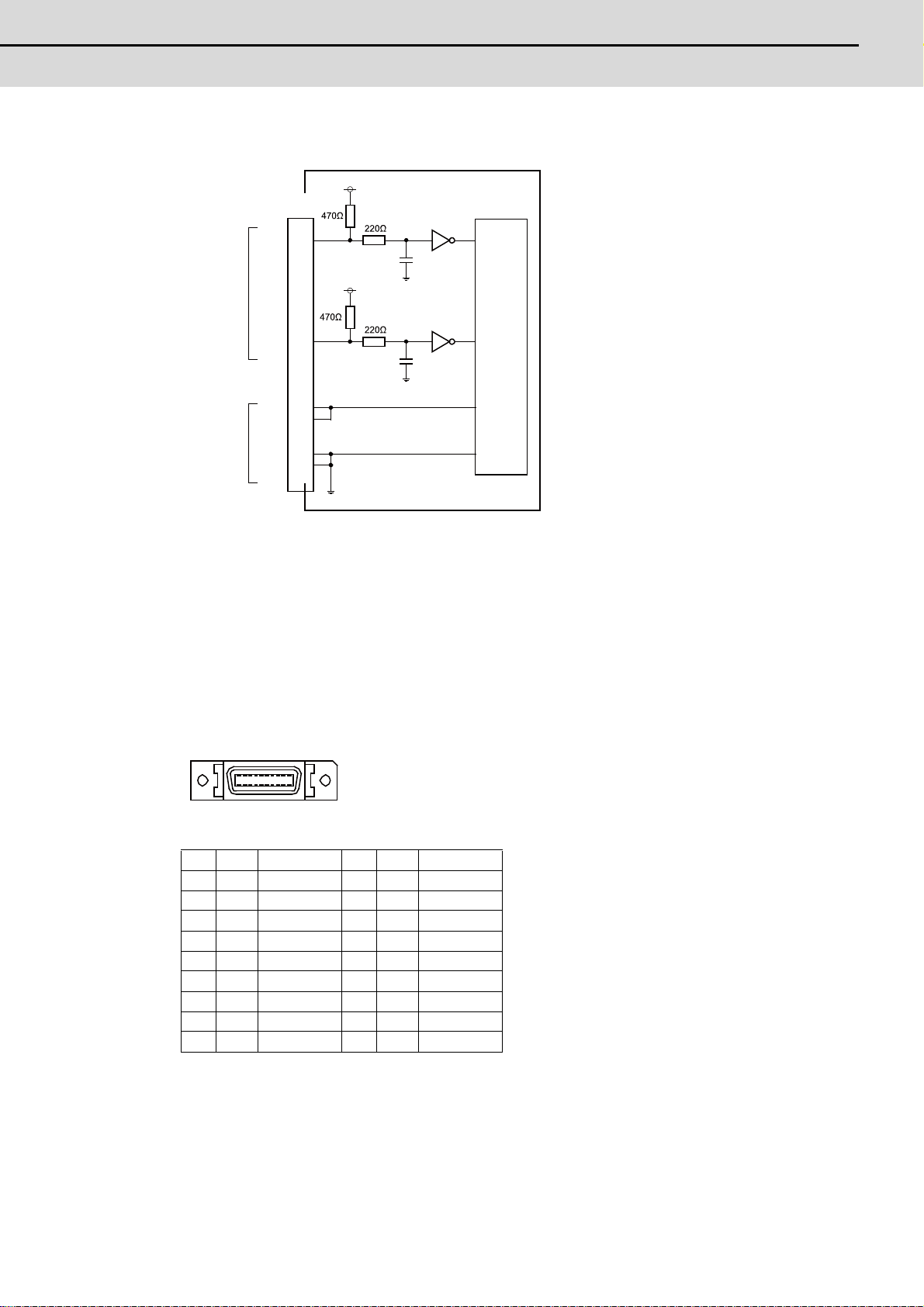
(c) 5V manual pulse generator input/output circuit
10 1
20 11
+5V
Connector
pin No.
4
HA1A
3
HA2A
4700pF
Signal
input
Power
output
HA1B
HA2B
+5V
+5V
0V
0V
+5V
14
13
10
20
1
11
0V
4700pF
0V
Control
circuit
0V
When using the synchronous feed encoder and the manual pulse generator at the same time, connect
the manual pulse generator to the operation panel I/O unit or use a distribution cable made by the
machine tool builder.
(14) Serial communication (RS-232C) I/F 2ch (SIO1)
(15) Serial communication (RS-232C) I/F 2ch (SIO2)
1 0V 11 0V
2 I RD1(RXD1) 12 OSD1(TXD1)
3 ICS1(CTS1) 13 ORS1(RTS1)
4 O DR1(DSR1) 14 IER1(DTR1)
5 0V 15 0V
6 NC 16 NC
7 I RD2(RXD2) 17 OSD2(TXD2)
8 ICS2(CTS2) 18 ORS2(RTS2)
9 O DR2(DSR2) 19 IER2(DTR2)
10 NC 20 NC
* Connect connector case with FG pattern.
<Cable side connector type>
Plug: 10120-3000VE
Shell: 10320-52F0-008
Recommended manufacturer: Sumitomo 3M
21
Page 44
2 General Specifications
MITSUBISHI CNC
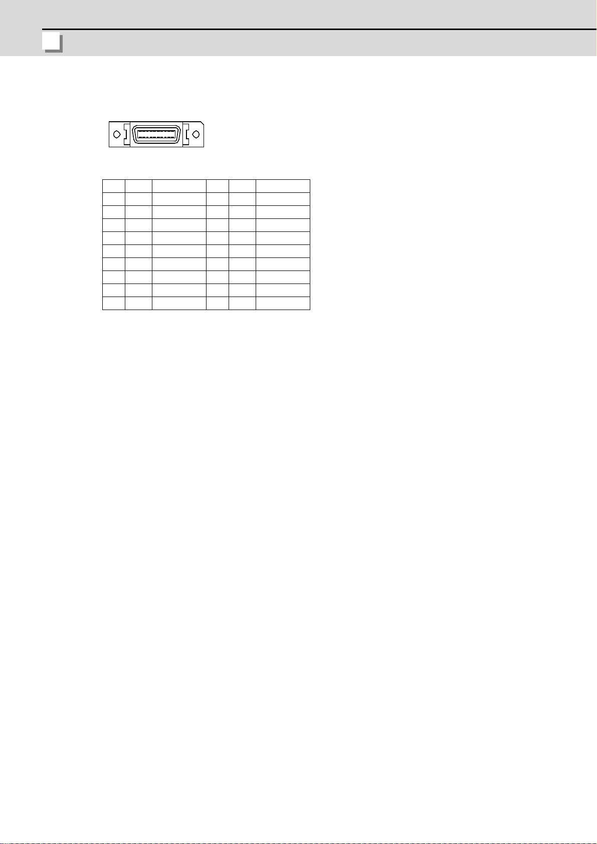
(16) Skip input 8ch (SKIP)
10 1
20 11
1 0V 11 0V
2 I SKIP0 12 I SKIP1
3 I SKIP2 13 I SKIP3
4 NC 14 NC
5 0V 15 0V
6 NC 16 NC
7 I SKIP4 17 I SKIP5
8 I SKIP6 18 I SKIP7
9 NC 19 NC
10 NC 20 NC
* Connect connector case with FG pattern.
<Cable side connector type>
Plug: 10120-3000VE
Shell: 10320-52F0-008
Recommended manufacturer: Sumitomo 3M
22
Page 45
M700VS Series Connection Manual
2.2 Control Unit
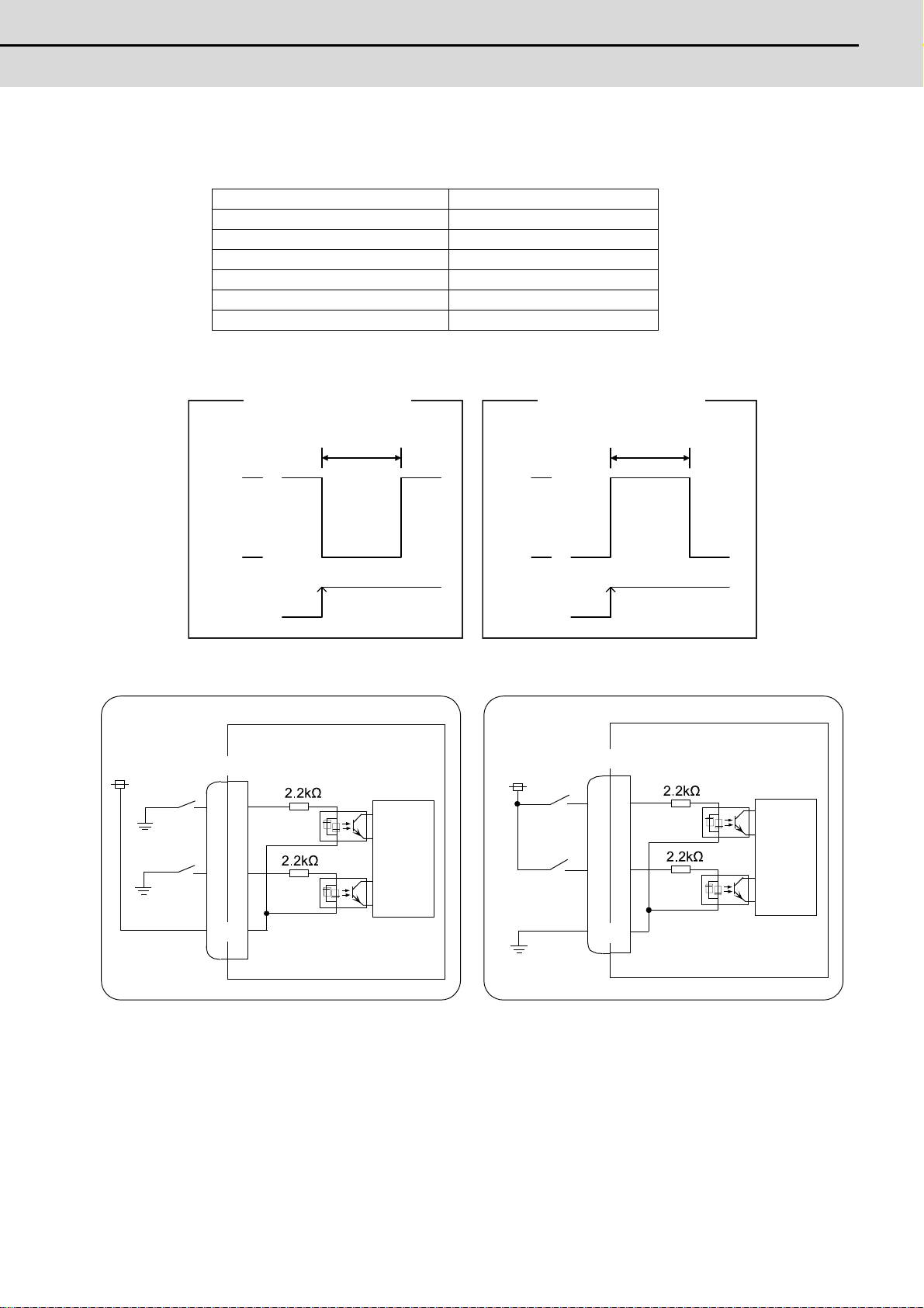
(a) Skip signal input conditions
0V
+24V
Ton
External signal
Internal signal
Connection to 24V common
0V
+24V
Ton
External signal
Internal signal
Connection to 0V common
0V(RG)
0V(RG)
0V(RG)
SKIP
SKIP
COM
COM
24VDC
(Machine side)
Control
circuit
Control
circuit
(Machine side)
Connection to 24V common
Connection to 0V common
24VDC
Use the input signal within the following condition ranges.
Input voltage at external contact ON 18V or more, 25.2V or less
Input current at external contact ON 6mA or more
Input voltage at external contact OFF 4V or less
Input current at external contact OFF 2mA or less
Input signal holding time (Ton) 2ms or more
Internal response time 0.08ms or less
Machine side contact capacity +30V or more, 16mA or more
(Note) "Input voltage at external contact ON" means the voltage between the external input signal and
the COM terminal.
(17) Battery (Q6BAT) I/F (BAT)
23
Page 46

2 General Specifications
MITSUBISHI CNC
(18) Optical communication I/F (OPT1)
Name
(19) Optical communication I/F (OPT2)
<Cable side connector type>
(PCF type)
Connector: CF-2D101-S
Recommended manufacturer: Japan Aviation Electronics
(POF type)
Connector: PF-2D101
Recommended manufacturer: Japan Aviation Electronics
(20) FG terminal (FG)
(21) Touch panel I/F (TP)
(22) LED
Name Function At fault Conditions
24VDCIN +24VDC input check Not lit
DCOUT Internal output voltage check Not lit
LCDON
PSEMG
WDER/
WDERS
BATALM Battery voltage drop Lit (Red) Battery voltage has dropped to 2.7V or less
+12VDC output voltage check
for backlight inverter
External emergency stop status display
System error display Lit (Red)
Not lit
Lit (Red) External emergency stop signal has inputted
(1) Failure of +24VDC input
(2) Disconnection of fuse
(1) Failure of internal voltage output in control unit
(2) Short circuit of +5VDC output on CG71 or ENC or FAN connector
(1) Failure of 12VDC output in control unit
(2) 24VDC input voltage is +20V or less
(1) Failure of control unit
(2) SRAM data is broken
24
Page 47

M700VS Series Connection Manual
2.3 Display Unit
2.3 Display Unit
(Space required for wiring)
200
260
20 110
260 ( )
250 ± 0.3
4- M3
200 ( )
190 ± 0.3
244
184
Unit outline
Unit outline
Screw
(Square hole)
Outline dimension
[FCU7-DU120-11 (8.4-type)]
(Note 1) The above side view shows the state with the control unit mounted.
(Note 2) Consider the minimum radius value of optical communication cable for the bottom space. (Refer to
"Connection : Precautions for Wiring : Precautions for Using Optical Communication Cable".)
<Panel cut dimension drawing>
25
Page 48

2 General Specifications
MITSUBISHI CNC
[FCU7-DU140-11 (10.4-type)]
(Space required for wiring)
290
220
20 11 0
(Note 1) The above side view shows the state with the control unit mounted.
(Note 2) Consider the minimum radius value of optical communication cable for the bottom space. (Refer to
"Connection : Precautions for Wiring : Precautions for Using Optical Communication Cable".)
<Panel cut dimension drawing>
Unit outline
220 ( )
204
210 ± 0.3
4- M3
Screw
290 (
280 ± 0.3
Unit outline
274
(Square hole)
)
26
Page 49

M700VS Series Connection Manual
2.3 Display Unit
[FCU7-DU140-31 (10.4-type with touch panel)]
(Space required for wiring)
290
220
20 110
290 (
)
280 ± 0.3
4- M3
220 ( )
210 ± 0.3
274
204
Unit outline
Screw
(Square hole)
Unit outline
(Note 1) The above side view shows the state with the control unit mounted.
(Note 2) Consider the minimum radius value of optical communication cable for the bottom space. (Refer to
"Connection : Precautions for Wiring : Precautions for Using Optical Communication Cable".)
<Panel cut dimension drawing>
27
Page 50

2 General Specifications
MITSUBISHI CNC
2.4 Keyboard Unit
140
200
20
110
(
Space required for wiring
)
Outline dimension
[FCU7-KB024 (8.4-type)]
(Note) The above side view shows the state with the operation panel I/O unit FCU7-DX720/DX721 mounted.
<Panel cut dimension drawing>
140
(Unit outline)
0
0.3
190 0.3
(Unit outline)
200
(Square hole)
122
4-M3
Screw
182
28
Page 51

M700VS Series Connection Manual
2.4 Keyboard Unit
[FCU7-KB026 (Clear keys for 8.4-type)]
140
200
20
110
(
Space required for wiring
)
140
0
122
182
200
0.3
4-M3
190 0.3
Screw
(Unit outline)
(Unit outline)
(Square hole)
(Note) The above side view shows the state with the operation panel I/O unit FCU7-DX720/DX721 mounted.
<Panel cut dimension drawing>
29
Page 52

2 General Specifications
MITSUBISHI CNC
[FCU7-KB029 (In tandem for 8.4-type)]
(
Space required for wiring
)
260
242
250
122
140
4-M3
130
0.3
0.3
Screw
(Unit outline)
(Unit outline)
(Square hole)
(Note) The above side view shows the state with the operation panel I/O unit FCU7-DX720/DX721 mounted.
<Panel cut dimension drawing>
30
Page 53

M700VS Series Connection Manual
2.4 Keyboard Unit
[FCU7-KB044 (10.4-type)]
140
220
20
110
(
Space required for wiring
)
140
0
122
202
220
0.3
4-M3
210 0.3
Screw
(Unit outline)
(Unit outline)
(Square hole)
(Note) The above side view shows the state with the operation panel I/O unit FCU7-DX720/DX721 mounted.
<Panel cut dimension drawing>
31
Page 54
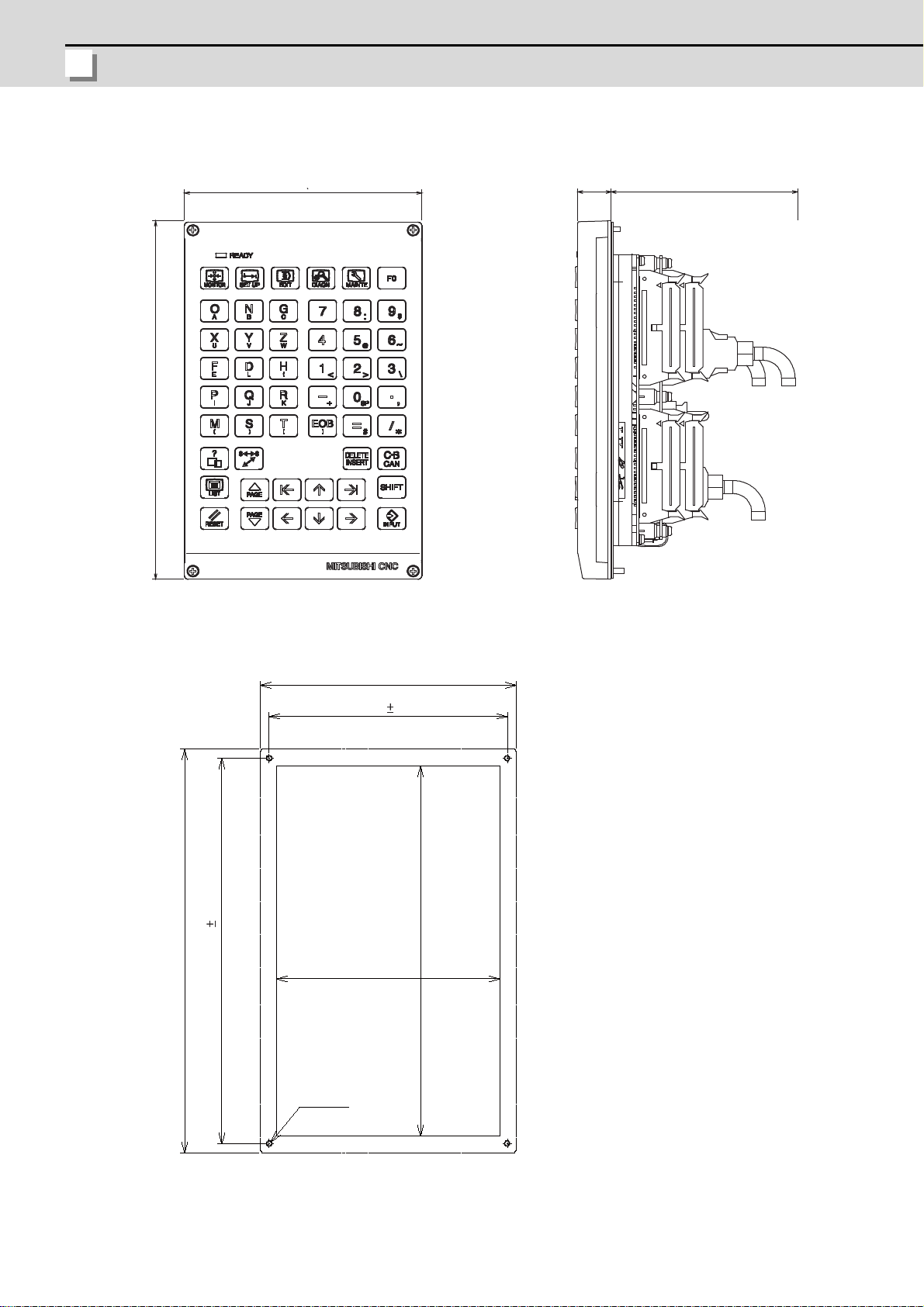
2 General Specifications
MITSUBISHI CNC
[FCU7-KB046 (Clear keys for 10.4-type)]
140
220
20
110
(
Space required for wiring
)
140
0
122
202
220
0.3
4-M3
210 0.3
Screw
(Unit outline)
(Unit outline)
(Square hole)
(Note) The above side view shows the state with the operation panel I/O unit FCU7-DX720/DX721 mounted.
<Panel cut dimension drawing>
32
Page 55

M700VS Series Connection Manual
2.4 Keyboard Unit
[FCU7-KB047 (Clear keys for 10.4-type/ QWERTY assignment)]
290
160
17
110
(
Space required for wiring
)
290
274
280
144
160
4-M3
150
0.3
0.3
Screw
(Unit outline)
(Unit outline)
(Square hole)
(Note) The above side view shows the state with the operation panel I/O unit FCU7-DX720/DX721 mounted.
<Panel cut dimension drawing>
33
Page 56
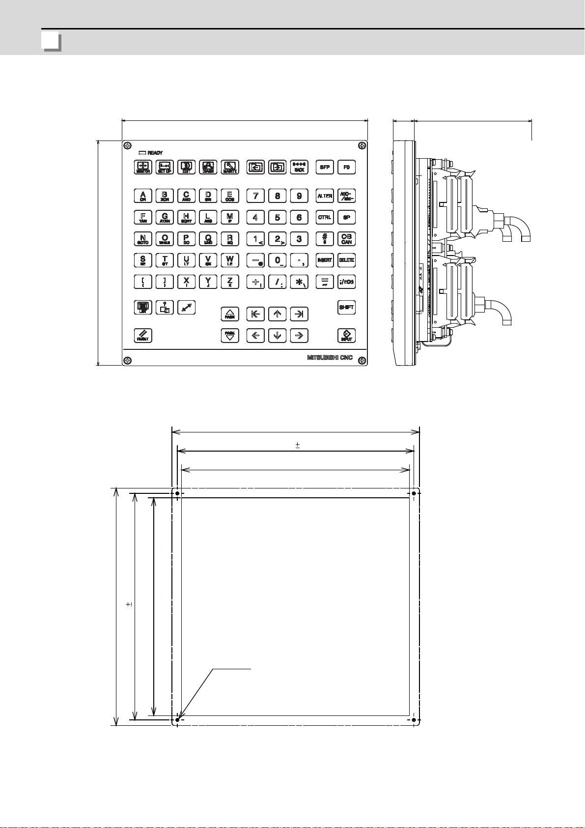
2 General Specifications
MITSUBISHI CNC
[FCU7-KB048 (Clear keys for 10.4-type)]
230
220
20
110
(
Space required for wiring
)
(Note) The above side view shows the state with the operation panel I/O unit FCU7-DX720/DX721 mounted.
<Panel cut dimension drawing>
230
(Unit outline)
0.3
220
212
(Unit outline)
210 0.3
220
202
4-M3
Screw
(Square hole)
34
Page 57

M700VS Series Connection Manual
2.5 Operation Panel I/O Unit
2.5 Operation Panel I/O Unit
Characteristics of operation panel I/O unit are as follows.
(1) Number of DI/DO points that can be mounted on the machine operation panel is 64/64 as standard and 96/96 at the
maximum. Both sink and source types are available.
Operation panel I/O unit DI/DO uses equivalent serial link connections as those used for remote I/O.
(2) Remote I/O interface --- 1ch
Remote I/O unit, scan I/O card, etc. can be extended up to 4 stations. Note that the following (a) and (b) will be
applied if DI/DO mounted on the operation panel I/O unit is used.
(a) When 64 points/64 points are used: Up to 4 stations, 128 points/128 points in total, are available.
(b) When 96 points/96 points are used: Up to 3 stations, 96 points/96 points in total, are available.
(3) Manual pulse generator --- 2ch
5V and 12V manual pulse generators can be connected.
(4) Installation on the back side of the keyboard unit is possible. Allows space saving inside the operation panel.
Classification Type Components Remarks
DI 24V/0V common input
DO Sink output
DI 24V/0V common input
DO Source output
DI 24V/0V common input
DO Sink output
DI 24V/0V common input
DO Source output
DI 24V/0V common input
DO Sink output
DI 24V/0V common input
DO Source output
FCU7-DX710
FCU7-DX711
FCU7-DX720
FCU7-DX721
FCU7-DX730
FCU7-DX731
Base card
Terminator (R-TM)
Base card
Terminator (R-TM)
Base card
Terminator (R-TM)
Add-on card
Base card
Terminator (R-TM)
Add-on card
Base card
Terminator (R-TM)
Add-on card
Base card
Terminator (R-TM)
Add-on card
DI: 64-points 24V/0V common type
DO: 64-points sink type
MPG:2ch
Occupied stations (fixed): 1, 2, 7, 8
RIO3 extensible stations: 3, 4, 5, 6
DI: 64-points 24V/0V common type
DO: 64-points source type
MPG:2ch
Occupied stations (fixed): 1, 2, 7, 8
RIO3 extensible stations: 3, 4, 5, 6
DI: 96-points 24V/0V common type
DO: 80-points sink type
MPG:2ch
AO: 1 point
Occupied stations (fixed): 1, 2, 3, 7, 8
RIO3 extensible stations: 4, 5, 6
DI: 96-points 24V/0V common type
DO: 80-points source type
MPG:2ch
AO: 1 point
Occupied stations (fixed): 1, 2, 3, 7, 8
RIO3 extensible stations: 4, 5, 6
DI: 96-points 24V/0V common type
DO: 96-points sink type
MPG: 2ch
Occupied stations (fixed): 1, 2, 3, 7, 8
RIO3 extensible stations: 4, 5, 6
DI: 96-points 24V/0V common type
DO: 96-points source type
MPG:2ch
Occupied stations (fixed): 1, 2, 3, 7, 8
RIO3 extensible stations: 4, 5, 6
(Note 1) The station Nos. occupied by the operation panel I/O unit cannot be changed. If the unit has rotary switches,
do not change the switch settings when shipped.
(Settings when shipped: CS1 -> 0/ CS2 -> 1/ CS3 -> 6)
(Note 2) Set the number of DI points that are simultaneously turned ON to be less than half of the total points. If many
points are set to be simultaneously turned ON in high temperature, operation panel I/O unit may be
deteriorated due to the heat.
35
Page 58

2 General Specifications
MITSUBISHI CNC
Dimension and names of parts
(4)
(5)
(1)
(10)
(2)
(7)
(8)
(11)
(12)
110 (
116
179
(13)
Space required for wiring)
NCKB
Connector
Fixing screw (4 pcs.)
M3x25
(with plain washer and spring washer)
[FCU7-DX710/ FCU7-DX711]
<Dimension drawing for installing on the panel> <Installation on the back side of the keyboard>
116 ( )
Unit outline
Operation panel I/O unit can be installed on the back side
of the keyboard.
106 ± 0.3
Unit outline
171 ± 0.3
179 ( )
4-M3
Screw
(Note) Use M3x25 screws (with spring washer and plain washer) when mounting the operation panel I/O unit.
36
Page 59
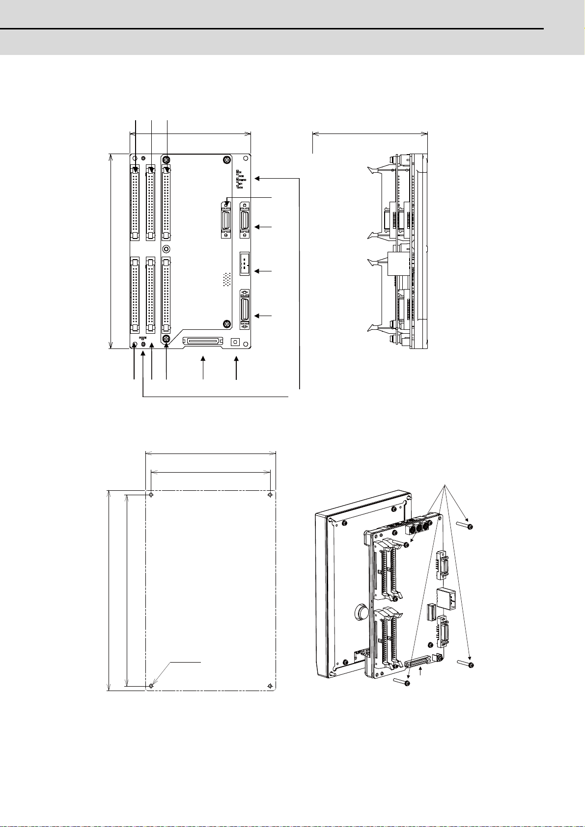
M700VS Series Connection Manual
2.5 Operation Panel I/O Unit
[FCU7-DX720/ FCU7-DX721/ FCU7-DX730/ FCU7-DX731]
(4)
(5)
(1)
(10)
110 (
(2)
(7)
(8)
(11)
(12)
(3)
(6)
(9)
116
179
(13)
Space required for wiring)
116 ( )
106 ± 0.3
4-M3
179 ( )
171 ± 0.3
Unit outline
Screw
Unit outline
NCKB
Connector
Fixing screw (4 pcs.)
M3x25
(with plain washer and spring washer)
<Dimension drawing for installing on the panel> <Installation on the back side of the keyboard>
Operation panel I/O unit can be installed on the back side
of the keyboard.
(Note) Use M3x25 screws (with spring washer and plain washer) when mounting the operation panel I/O unit.
37
Page 60

2 General Specifications
MITSUBISHI CNC
(1) Machine input (CG31)
B1 B20
A1 A20
Digital input 32 points (1st station)
(2) Machine input (CG33)
Digital input 32 points (2nd station)
(3) Machine input (CG35)
Digital input 32 points (3rd station)
<Cable side connector type>
Connector: 7940-6500LC
Recommended manufacturer: Sumitomo 3M
CG31 CG33 CG35
BA BA BA
20 I X200 20 IX210 20 I X220 20 I X230 20 IX240 20 I X250
19 I X201 19 IX211 19 I X221 19 I X231 19 IX241 19 I X251
18 I X202 18 IX212 18 I X222 18 I X232 18 IX242 18 I X252
17 I X203 17 IX213 17 I X223 17 I X233 17 IX243 17 I X253
16 I X204 16 IX214 16 I X224 16 I X234 16 IX244 16 I X254
15 I X205 15 IX215 15 I X225 15 I X235 15 IX245 15 I X255
14 I X206 14 IX216 14 I X226 14 I X236 14 IX246 14 I X256
13 I X207 13 IX217 13 I X227 13 I X237 13 IX247 13 I X257
X
12 I X208 12 IX218 12 I
11 I X209 11 IX219 11 I X229 11 I X239 11 IX249 11 I X259
10 I X20A 10 IX21A 10 I X22A 10 I X23A 10 IX24A 10 I X25A
9 I X20B 9 IX21B 9 I X22B 9 I X23B 9 IX24B 9 I X25B
8 I X20C 8 IX21C 8 I X22C 8 I X23C 8 IX24C 8 I X25C
7 I X20D 7 IX21D 7 I X22D 7 I X23D 7 IX24D 7 I X25D
6 I X20E 6 IX21E 6 I X22E 6 I X23E 6 IX24E 6 I X25E
5 I X20F 5 IX21F 5 I X22F 5 I X23F 5 IX24F 5 I X25F
4 NC 4 NC 4 NC 4 NC 4 NC 4 NC
3 CO
2 I
1 I +24V 1 0V 1 I +24V 1 0V 1 I+24V 1 0V
M 3 COM 3 COM 3 COM 3 COM 3 COM
+24V 2 0V 2 I +24V 2 0V 2 I+24V 2 0V
228 12 I X238 12 IX248 12 I X258
Each station has fixed input/output assignments. Refer to "PLC Interface Manual" for details.
38
Page 61

M700VS Series Connection Manual
2.5 Operation Panel I/O Unit
(a) Outline of digital signal input circuit
A
A
R
0V
FG
COM
0V
FG
COM
R
CG31/CG33/CG35
CG31/CG33/CG35
24VDC(+)
Control
circuit
(Machine side)
Stabilized
power supply
External contact
Input voltage
Input resistor
24VDC(+)
Input voltage
24V common
0V common
Control
circuit
(Machine side)
Stabilized
power supply
External contact
Input resistor
Both 24V common and 0V common connections are allowed in the digital signal input circuit.
Follow the wiring diagram below for each type.
Input circuit
3.3k
3,B3
3.3k
3,B3
Input conditions
The input signals must be used within the following condition ranges.
24V common 0V common
1 Input voltage at external contact ON 6V or less 18V or more, 25.2V or less
2 Input current at external contact ON 9mA or more
3 Input voltage at external contact OFF 20V or more, 25.2V or less 4V or less
4 Input current at external contact OFF 2mA or less
5 Input resistance Approx. 3.3kΩ
6 Tolerable chattering time (T1) 3ms
7 Input signal holding t ime (T2) 40ms or more (Note)
input circuit operation delay time
8
(T3 and T4)
3ms ≤ T3 ≈ T4 ≤ 16ms
9 Machine side contact capacity 30V or more, 16mA or more
(Note) Input signal holding time: The guide is 40ms or more. The input signal will not be
recognized unless it is held for the ladder processing cycle time or longer.
Connection to 24V common input Connection to 0V common input
T2
(E)
(I)
T1T1
+24V
GND
(E)
+24V
GND
(I)
T4T3
(E) : External signal, (I):Internal signal
T2
T1T1
T4T3
39
Page 62

2 General Specifications
MITSUBISHI CNC
(4) Machine output (CG32)
B1 B20
A1 A20
Digital output 32 points (1st station)
(5) Machine output (CG34)
Digital output 32 points (2nd station)
(6) Machine output (CG36)
FCU7-DX730/DX731: Digital output 32 points (3rd station)
FCU7-DX720/DX721: Digital output 16 points (3rd station) (with analog output)
<Cable side connector type>
Connector: 7940-6500LC
Recommended manufacturer: Sumitomo 3M
CG32 CG34 CG36 (Note)
BA BA BA
20 O Y200 20 OY210 20 O Y220 20 O Y230 20 OY240 20 O Y250
19 O Y201 19 OY211 19 O Y221 19 O Y231 19 OY241 19 O Y251
18 O Y202 18 OY212 18 O Y222 18 O Y232 18 OY242 18 O Y252
17 O Y203 17 OY213 17 O Y223 17 O Y233 17 OY243 17 O Y253
16 O Y204 16 OY214 16 O Y224 16 O Y234 16 OY244 16 O Y254
15 O Y205 15 OY215 15 O Y225 15 O Y235 15 OY245 15 O Y255
14 O Y206 14 OY216 14 O Y226 14 O Y236 14 OY246 14 O Y256
13 O Y207 13 OY217 13 O Y227 13 O Y237 13 OY247 13 O Y257
228 12 O Y238 12 OY248 12 O Y258
12 O Y208 12 OY218 12 O
11 O Y209 11 OY219 11 O Y229 11 O Y239 11 OY249 11 O Y259
10 O Y20A 10 OY21A 10 O Y22A 10 O Y23A 10 OY24A 10 O Y25A
9 O Y20B 9 OY21B 9 O Y22B 9 O Y23B 9 OY24B 9 O Y25B
8 O Y20C 8 OY21C 8 O Y22C 8 O Y23C 8 OY24C 8 O Y25C
7 O Y20D 7 OY21D 7 O Y22D 7 O Y23D 7 OY24D 7 O Y25D
6 O Y20E 6 OY21E 6 O Y22E 6 O Y23E 6 OY24E 6 O Y25E
5 O Y20F 5 OY21F 5 O Y22F 5 O Y23F 5 OY24F 5 O Y25F
4 COM 4 COM 4 COM 4 COM 4 COM 4 COM
3 CO
2 I
1 I +24V 1 0V 1 I +24V 1 0V 1 I+24V 1 0V
M 3 COM 3 COM 3 COM 3 COM 3 COM
+24V 2 0V 2 I +24V 2 0V 2 I+24V 2 0V
Y
(Note) FCU7-DX720/DX721 uses 16 points of digital outputs, Y240 to Y24F.
Each station has fixed input/output assignments. Refer to "PLC Interface Manual" for details.
40
Page 63

M700VS Series Connection Manual
2.5 Operation Panel I/O Unit
(a) Outline of digital signal output circuit
R
RA
CG32/CG34/CG36
PL
R
RA
CG32/CG34/CG36
PL
RA
PL
24VDC(+)
24VDC(+)
Sink type (DX7x0)
Source type
(DX7x1)
Control
Circuit
(Macine side)
Control
Circuit
(Macine side)
: Relay
: Pilot lamp
CAUTION
The digital signal output circuit uses a sink type (DX7x0) or source type (DX7x1).
Use within the specification ranges shown below.
Output circuit
Output conditions
(Note 1) When using an inductive load such as a relay, always connect a diode (voltage resistance 100V
(Note 2) When using a capacitive load such as a lamp, always connect a protective resistor (R=150Ω)
Insulation method Insulation
Rated load voltage 24VDC
Max. output current 60mA/point
Output delay time 40μs
or more, 100mA or more) in parallel to the load.
serially to the load to suppress rush currents. (Make sure that the current is less than the
above tolerable current including the momentary current.)
1. When using an inductive load such as a relay, always connect a diode in parallel to the load.
2. When using a capacitive load such as a lamp, always connect a protective resistor serially
to the load to suppress rush currents.
41
Page 64

2 General Specifications
MITSUBISHI CNC
(7) Keyboard I/F (NCKB)
10 1
20 11
DAC
Ω
AO
AO*
OV
(8) FG terminal (FG)
(9) Analog output 1ch (AO)
1 GND 11 NC
2 NC 12 NC
3 NC 13 NC
4 NC 14 NC
5 NC 15 NC
6 NC 16 NC
7 AO 17 NC
8 NC 18 NC
9 NC 19 NC
10 NC 20 NC
* Connect connector case with FG pattern.
<Cable side connector type>
Plug: 10120-3000VE
Shell: 10320-52F0-008
Recommended manufacturer: Sumitomo 3M
Output circuit
R
R
Output conditions
Output voltage 0V to ±10V (±5%)
Resolution 12bit (±10V × n/4096) (Note)
Load conditions 10kΩ load resistance
Output impedance 220Ω
0
(Note) n=(2
to 211)
Connector pin assignment
1 AO* GND
7 AO Analog voltage output
42
Page 65

M700VS Series Connection Manual
2.5 Operation Panel I/O Unit
(10) Manual pulse generator input 2ch (5V and 12V) (MPG)
10 1
20 11
T
b da c e
A(B) phase
B(A) phase
1 GND 11 GND
2 reserve 12 reserve
3 IHA2A 13 IHA2B
4 IHA1A 14 IHA1B
5 GND 15 GND
6 O 24VDC 16 O24VDC
7 reserve 17 reserve
8 reserve 18 reserve
9 reserve 19 reserve
10 O5VDC 20 O5VDC
* Connect connector case with FG pattern.
<Cable side connector type>
Plug: 10120-3000VE
Shell: 10320-52F0-008
Recommended manufacturer: Sumitomo 3M
<Input conditions>
5V manual pulse generator input con-
Input pulse signal type A and B phases (with phase difference 90°) (Refer to the waveform below.)
Input signal voltage
Max. input pulse frequency 100kHz
Pulse generators power supply
voltage
Current consumption 100mA or less
Number of pulses per rotation 25 pulse/rev or 100 pulse/rev
Cable length 20m or less 50m or less
ditions
H level 3.5V to 5.25V
L level 0V to 0.5V
5VDC±10% 12VDC±10%
12V manual pulse generator input
conditions
a.b.c.d.e: A phase or B phase rising edge (falling edge) phase difference = T/4 ± T/10
T: A or B phase cycle (Min. 10μs)
43
Page 66

2 General Specifications
MITSUBISHI CNC
<Input/output circuit>
0V
+5V
4
3
14
13
10
20
1
11
0V
+5V
+5V
+5V
0V
0V
0V
6
16
+12V
+12V
5V
12V
HA1A
HA2A
HA1B
HA2B
Connector
pin No.
Signal
input
Power
output
Power
output
Control
unit
13
(11) Remote I/O unit I/F (RIO3)
1 I/O TXRX3
2 I/O TXRX3*
3 0V(GND)
<Cable side connector type>
Connector: 1-178288-3
Contact: 1-175218-2 x3
Recommended manufacturer: Tyco Electronics AMP
Refer to the following chart for the maximum number of connecting stations and I/O points.
Operation panel I/O unit type
FCU7-DX710/DX711
FCU7-DX720/DX721
FCU7-DX730/DX731
(Note) Refer to the section "General Specifications: Remote I/O Unit" for the number of occupying stations and I/
O points of remote I/O units.
Max. number of stations
(RIO3 connection)
4 stations
(stations 3rd to 6th can be used)
3 stations
(stations 4th to 6th can be used)
3 stations
(stations 4th to 6th can be used)
Max. number of I/O points
(RIO3 connection)
128 points/128 points
96 points/96 points
96 points/96 points
44
(12) Control unit I/F (CG71)
Page 67

M700VS Series Connection Manual
2.5 Operation Panel I/O Unit
(13) LED
Name Function At fault Conditions
3VON +3VDC input check Not lit (1) Disconnection between control unit and operation panel I/O unit
5VON +5VDC input check Not lit
PACKETNG
RIO1
12VON
DOCOM
RIO communication
status check
RIO communication
status check
For manual pulse
generator
+24VDC input check
(for source output)
Lit (Red)
Not lit
Not lit
(1) Disconnection between control unit and operation panel I/O unit
(2) Short circuit of manual pulse generator cable
(1) Partial disconnection between control unit and operation panel I/O unit
(2) Miswiring of extended I/O unit to RIO3
Short circuit of manual pulse generator cable
(1) Disconnection of 24V input
(2) Disconnection of protection fuse on the operation panel I/O unit
(Note) Sink output type does not have the LED for DOCOM.
45
Page 68

2 General Specifications
MITSUBISHI CNC
2.6 Remote I/O Unit
The following eight types of signals can be input/output from the remote I/O unit (FCUA-DX***) according to the type and
No. of contacts. Use serial link connections to connect the unit with the control unit or the operation panel I/O unit.
Multiple remote I/O units can be used as long as the total number of occupied stations is eight or less.
Classification Type Components Remarks
24V/0V common input + Sink output FCUA-DX100 RX311
24V/0V common input + Sink output FCUA-DX110 RX311+RX321-1
24V/0V common input + Sink output
+ Analog output
24V/0V common input + Sink output
+ Analog input/output
24V/0V common input + Source output FCUA-DX101 RX312
24V/0V common input + Source output FCUA-DX111 RX312+RX322-1
24V/0V common input + Source output +
Analog output
24V/0V common input + Source output +
Analog input/output
FCUA-DX120 RX311+RX321
FCUA-DX140 RX311+RX341
FCUA-DX121 RX312+RX322
FCUA-DX141 RX312+RX341
DI: 32-points 24V/0V common type
(photo coupler insulation)
DO: 32-points sink type (non-insulation)
Number of occupied stations: 1
DI: 64-points 24V/0V common type
(photo coupler insulation)
DO: 48-points sink type (non-insulation)
Number of occupied stations: 2
DI: 64-points 24V/0V common type
(photo coupler insulation)
DO: 48-points sink type (non-insulation)
AO: 1 point
Number of occupied stations: 2
DI: 32-points 24V/0V common type
(photo coupler insulation)
DO: 32-points sink type (non-insulation)
AI: 4 points
AO: 1 point
Number of occupied stations: 2
DI: 32-points 24V/0V common type
(photo coupler insulation)
DO: 32-points source type (non-insulation)
Number of occupied stations: 1
DI: 64-points 24V/0V common type
(photo coupler insulation)
DO: 48-points source type (non-insulation)
Number of occupied stations: 2
DI: 64-points 24V/0V common type
(photo coupler insulation)
DO: 48-points source type (non-insulation)
AO: 1 point
Number of occupied stations: 2
DI: 32-points 24V/0V common type
(photo coupler insulation)
DO: 32-points source type (non-insulation)
AI: 4 points
AO: 1 point
Number of occupied stations: 2
46
Page 69

M700VS Series Connection Manual
2.6 Remote I/O Unit
Dimension and names of parts
(2)
(4)
(5)
(8)
(9)
(10)
(1)
(6)
(7)
(3)
(7)
(7)
(1)
(6)
(7)
(3)
(1)
(6)
(7)
(3)
[Front view]
[Side view][Bottom view]
6
135
168
40
40 40
135
168
168
168
70
6
135
168150 100
634
156
6
6
2-M5 screw
Mounting hole
Bottom
To p
(Front)
(Rear)
<Installation dimension drawing>
47
Page 70

2 General Specifications
MITSUBISHI CNC
(1) Machine input (DI-L)
A
A
R
0V
FG
COM
0V
FG
COM
R
DI-L / DI-R
2.2k
DI-L / DI-R
2.2k
24VDC(+)
Control
circuit
(Machine side)
Stabilized
power supply
External contact
Input voltage
Input resistor
24VDC(+)
Input voltage
24V common
0V common
Control
circuit
(Machine side)
Stabilized
power supply
External contact
Input resistor
T1T1
T2
T4T3
GND
+24V
(E)
(I)
(2) Machine input (DI-R)
Both 24V common and 0V common connections are allowed in the digital signal input circuit.
Follow the wiring diagram below for each type.
Input circuit
3,B3
3,B3
Input conditions
The input signals must be used within the following condition ranges.
24V common 0V common
1 Input voltage at external contact ON 6V or less 18V or more, 25.2V or less
2 Input current at external contact ON 9mA or more
3 Input voltage at external contact OFF 20V or more, 25.2V or less 4V or less
4 Input current at external contact OFF 2mA or less
5 Input resistance Approx. 2.2kΩ
6 Tolerable chattering time (T1) 3ms
7 Input signal holding time (T2) 40ms or more (Note)
input circuit operation delay time (T3
8
and T4)
3ms ≤ T3 ≈ T4 ≤ 16ms
9 Machine side contact capacity 30V or more, 16mA or more
(Note) Input signal holding time: The guide is 40ms or more. The input signal will not be recognized unless
it is held for the ladder processing cycle time or longer.
Connection to 24V common input Connection to 0V common input
T2
(E)
+24V
T1T1
(E) : External signal, (I) : Internal signal
48
GND
(I)
T4T3
Page 71
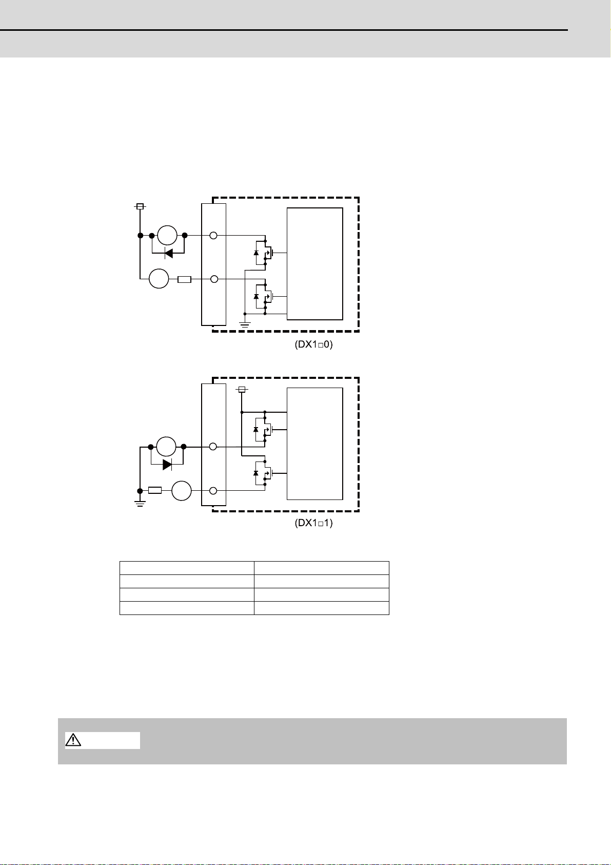
M700VS Series Connection Manual
2.6 Remote I/O Unit
(3) Machine output (DO-L)
R
RA
DO-L/DO-R
PL
R
DO-L/DO-R
RA
PL
Sink type
Source type
24VDC(+)
Control
circuit
(Machine side)
Control
circuit
(Machine side)
24VDC(+)
CAUTION
(4) Machine output (DO-R)
The digital signal output circuit uses a sink type (DX1*0) or source type (DX1*1).
Use within the specification ranges shown below.
Output circuit
Output conditions
(Note 1) When using an inductive load such as a relay, always connect a diode (voltage resistance 100V or more,
(Note 2) When using a capacitive load such as a lamp, always connect a protective resistor (R=150Ω) serially to
Insulation method Non-insulation
Rated load voltage 24VDC
Max. output current 60mA/point
Output delay time 40μs
100mA or more) in parallel to the load.
the load to suppress rush currents. (Make sure that the current is less than the above tolerable current
including the momentary current.)
1. When using an inductive load such as a relay, always connect a diode in parallel to the load.
2. When using a capacitive load such as a lamp, always connect a protective resistor serially
to the load to suppress rush currents.
49
Page 72

2 General Specifications
MITSUBISHI CNC
(5) Analog signal input/output (AIO)
(a) Outline of analog signal output circuit
The analog signal output circuit can be used only for FCUA-DX120/DX121/DX140/DX141.
Output circuit
220
A0
A0*
Output conditions
Output voltage 0V to ±10V (±5%)
Resolution 12bit (±10V × n/4096) (Note)
Load conditions 10kΩ load resistance
Output impedance 220Ω
R
R
DAC
OV(RG)
(Note) n=(20 to 211)
(b) Outline of analog signal input circuit
The analog signal input circuit can be used only for FCUA-DX140/DX141.
Input circuit
AI
AI*
Input conditions
Max. input rating ±15V
Resolution 10V/2000 (5mV)
Precision Within ±25mV
AD input sampling time 14.2ms(AI0)/ 42.6ms(AI1 to 3)
150
OV(RG)
ADC
50
Page 73

M700VS Series Connection Manual
2.6 Remote I/O Unit
(6) Transfer speed changeover switch (DS)
A
Selection of station No.
13
13
Not used
Not used
(7) Station No. changeover switch (CS)
4
3
5
2
6
1
7
0
8
F
9
E
D
B
C
(8) Remote I/O unit I/F #1 (RIO1)
(9) Remote I/O unit I/F #2 (RIO2)
1 I/O TXRX
2 I/O TXRX*
3 0V
<Cable side connector type>
Connector: 1-178288-3
Contact: 1-175218-2 x3
Recommended manufacturer: Tyco Electronics AMP
(10) 24VDC input (DCIN)
1 I +24V
2 0V
3 FG
<Cable side connector type>
Connector: 2-178288-3
Contact: 1-175218-5 x3
Recommended manufacturer: Tyco Electronics AMP
51
Page 74

2 General Specifications
MITSUBISHI CNC
2.7 Scan I/O Unit
The HR347/357 card is the machine operation panel input/output card. It has a digital input/output and scan input/output,
and is connected to the machine operation panel and other devices.
Item HR347 HR357
Number of points 64 points
Configuration 8 common × 8 data matrix
Input
Scan
Output
Input
Digital
Output
(*1) Input signal holding time: The guide is 11.68ms or more. The input signal will not be recognized unless it is
Rated voltage 5VDC
Max. current 80mA/point
Input cycle 1.46ms cycle, 11.68ms cycle
Input signal holding time 11.68ms or more (*1)
Number of points 64 points
Configuration 4 common × 8 data + 4 common × 8 data matrix
Rated load voltage 5VDC
Max. output current 200mA/point
Output cycle 1.46ms cycle, 5.84ms cycle
Number of points 32 points
Type 24V common/ 0V common
Input voltage at external contact ON 6V or less 18V or more, 25.2V or less
Input current at external contact ON 2mA or less 9mA or more
Input voltage at external contact OFF 20V or more, 25.2V or less 4V or less
Input current at external contact OFF 9mA or more 2mA or less
Tolerable chattering time 2.2ms or less
Input signal holding time 40ms or more
Input circuit operation delay time 2.2ms ≤ T3 ≈ T4 ≤ 11ms
Machine side contact capacity 30V or more, 16mA or more
Number of points 32 points
Rated load voltage 24VDC
Max. output current 60mA/point
Type Sink Source
held for the ladder processing cycle time or longer.
52
Page 75

M700VS Series Connection Manual
2.7 Scan I/O Unit
Dimension and names of parts
A
B
25
1
CF35
(Scan DI/DO : 64/64)
ISP
81
DIO
SCAN2 SCAN1
RIO3 DCIN
BA
CF31
CF33
20
1
20
1
(DO : 32)
(DO : 32)
ALM3
24IN
ALM2
5OUT
ALM1
7
0.3
166
7
180
20
20
4.5
4-C2
150
0.3
110
(6)
(1) (2)
(3)
(7)
(8)
(4)
(5)
[HR347/ HR357]
53
Page 76
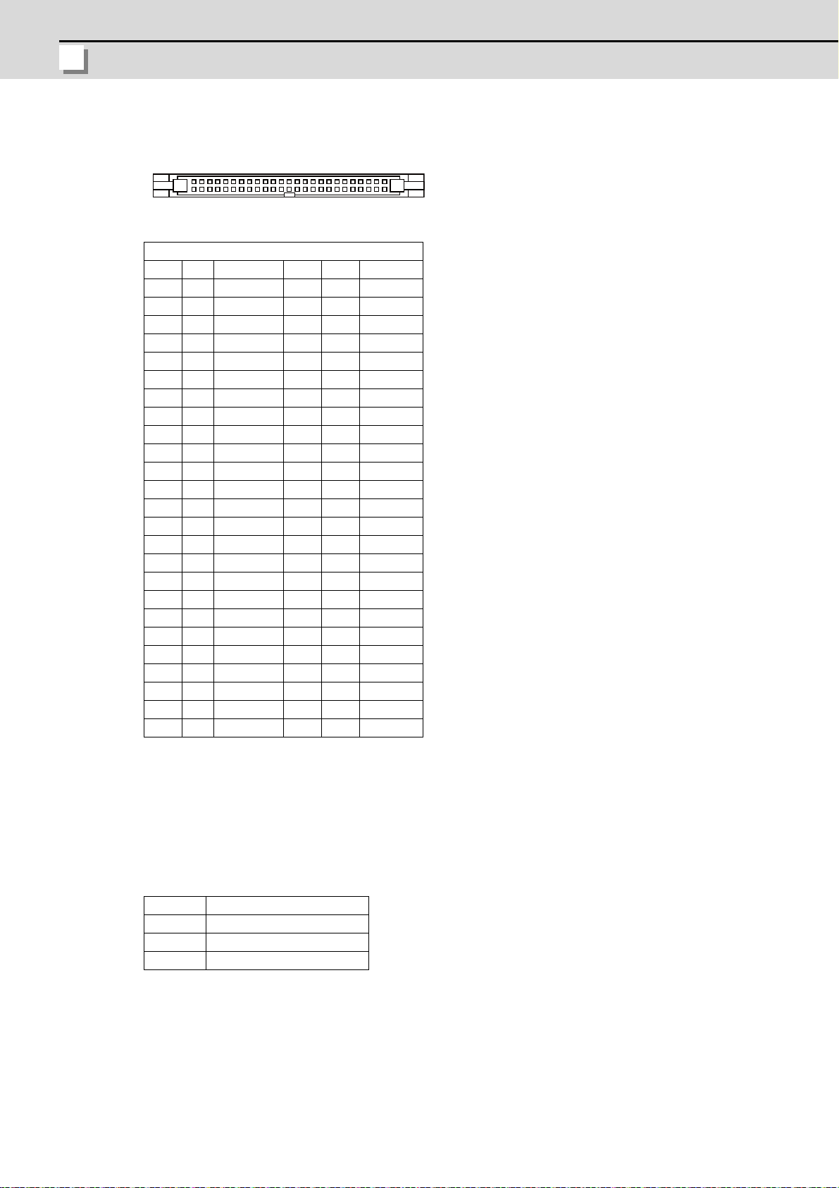
2 General Specifications
MITSUBISHI CNC
(1) Scan type input/output (CF35)
B1 B25
A1 A25
CF35
BA
25 GND 25 GND
24 O LC3B 24 O LC3A
23 O LC2B 23 O LC2A
22 O LC1B 22 O LC1A
21 O LC0B 21 O LC0A
20 I LD7B* 20 I LD7A*
19 I LD6B* 19 I LD6A*
18 I LD5B* 18 I LD5A*
17 I LD4B* 17 I LD4A*
16 I LD3B* 16 I LD3A*
15 I LD2B* 15 I LD2A*
14 I LD1B* 14 I LD1A*
13 I LD0B* 13 I LD0A*
12 GND 12
11 11
10 10
9 O KYC7* 9 O KYC6*
8 O KYC5* 8 O KYC4*
7 O KYC3* 7 O KYC2*
6 O KYC1* 6 O KYC0*
5 I KYD7* 5 I KYD6*
4 I KYD5* 4 I KYD4*
3 I KYD3* 3 I KYD2*
2 I KYD1* 2 I KYD0*
11GND
(Note) The GND pin is normally unused.
Do not connect the GND pin to the frame ground.
<Cable side connector type>
Connector: 7950-6500SC
Relief: 3448-7950
Recommended manufacturer: Sumitomo 3M
LCxA/B Common signals for scan DO
LDxA/B* Data signals for scan DO
KYCx* Common signals for scan DI
KYDx* Data signals for scan DI
* This is an example when SCAN1 is set to "0", SCAN2 to "1", and DIO to "2".
Refer to "PLC Interface Manual" for details.
54
Page 77

M700VS Series Connection Manual
2.7 Scan I/O Unit
(a) Scan input
CF35
KYCO*
KYC1*
KYC2*
KYC3*
KYC4*
KYC5*
KYC6*
KYC7*
KYD7*
KYD6*
KYD5*
KYD4*
KYD3*
KYD2*
KYD1*
KYD0*
X07
X0F
X17
X1F
X27
X2F
X37
X3F
X06
X0E
X16
X1E
X26
X2E
X36
X3E
X05
X0D
X15
X1D
X25
X2D
X35
X3D
X04
X0C
X14
X1C
X24
X2C
X34
X3C
X03
X0B
X13
X1B
X23
X2B
X33
X3B
X02
X0A
X12
X1A
X22
X2A
X32
X3A
X01
X09
X11
X19
X21
X29
X31
X39
X00
X08
X10
X18
X20
X28
X30
X38
<Example of a circuit manufactured by the machine tool builder>
KYCO*
KYC7*
KYDO*
KYD7*
to
to
Sneak path
prevention diode
An example is shown of a scan input circuit manufactured by the machine manufacturer.
(Note) To scan input, connect a sneak path prevention diode as shown in the following drawing. The
unit may not be able to read the correct input signals without a sneak path prevention diode
installed.
The common signals are changed over with scan input as shown in the following drawing. Key input data
can be received when the common signal is LOW. The common signal changeover cycle is 11.68ms, but
the input signal will not be recognized unless it is held for the ladder processing cycle time or longer. The
scan input is a 5V system.
KYCO*
KYC1*
KYC2*
KYC3*
KYC4*
KYC5*
KYC6*
KYC7*
11.68ms
1.46ms
55
Page 78

2 General Specifications
MITSUBISHI CNC
(b) Scan output
CF35
LC3A
LC2A
LC1A
LC0A
LD0A*
LD1A*
LD2A*
LD3A*
LD4A*
LD5A*
LD6A*
LD7A*
Y00
Y01
Y02
Y03
Y04
Y05
Y06
Y07
Y08
Y09
Y0A
Y0B
Y0C
Y0D
Y0E
Y0F
Y10
Y11
Y12
Y13
Y14
Y15
Y16
Y17
Y18
Y19
Y1A
Y1B
Y1C
Y1D
Y1E
Y1F
CF35
LC3B
LC2B
LC1B
LC0B
LD0B*
LD1B*
LD2B*
LD3B*
LD4B*
LD5B*
LD6B*
LD7B*
Y20
Y21
Y22
Y23
Y24
Y25
Y26
Y27
Y28
Y29
Y2A
Y2B
Y2C
Y2D
Y2E
Y2F
Y30
Y31
Y32
Y33
Y34
Y35
Y36
Y37
Y38
Y39
Y3A
Y3B
Y3C
Y3D
Y3E
Y3F
<Example of a circuit manufactured
by the machine tool builder>
<Example of a circuit manufactured
by the machine tool builder>
HR3 7
5V
LCnA/B
LDnA/B*
330
0V(RG)
CF35
<Manufactured by the machine tool builder>Output circuit
An example is shown of a scan output circuit manufactured by the machine manufacturer.
The common signals are changed over with scan output as shown in the following drawing. The LED
outputs data, and lights only when the common signal is HIGH. The common signal changes to 4 signals
in succession, and light s once every 5.84ms for 1.46ms only. The scan output is a 5V system.
LC3A
LC2A
LC1A
LC0A
56
1.46ms
5.84ms
1.46ms
5.84ms
LC3B
LC2B
LC1B
LC0B
Page 79

M700VS Series Connection Manual
2.7 Scan I/O Unit
(2) LED
0
0
0
SCAN1 0
SCAN2 1
DIO 2
CF35
DI:32 DO:32
DO:32DI:32
X00
X1F
X20
X3F
Y00
Y1F
Y20
Y3F
CF31 CF33
DI:32
X40
X5F
DO:32
Y40
Y5F
SCAN1
SCAN2
DIO
Standard setting
[Address]
[Address]
[Address]
[Address]
[Address] [Address]
Scan Scan
ScanScan
Digital Digital
LED Function Color
24IN 24VDC input check Green Lit Not lit 24VDC voltage check
5OUT Internal output voltage check Green Lit Not lit Contact the MITSUBISHI service dept.
ALM1
ALM2
ALM3
Communication error of the station
designated by rotary switch "SCAN1"
Communication error of the station
designated by rotary switch "SCAN2"
Communication error of the station
designated by rotary switch "DIO"
Red Not lit Lit
Red Not lit Lit
Red Not lit Lit
Status
Normal At fault
Remedy
Check the station No. designation by the rotary
switch of the remote I/O unit.
Check the station No. designation by the rotary
switch of the remote I/O unit.
Check the station No. designation by the rotary
switch of the remote I/O unit.
(3) Rotary switch
Set the address (station No.) assignment in DI/DO: 32/32 point units. Set using SCAN1, SCAN 2 and DIO rotary
switches. The assignment address is changed with the rotary switch setting.
Rotary switch Description
SCAN1 For scan input/output station No. setting 32points/32points (Normally set to "0")
SCAN2 For scan input/output station No. setting 32points/32points (Normally set to "1")
DIO For digital input/output station No. setting 32points/32points (Normally set to "2")
(Note) Set each different station Nos. for SCAN1, SCAN2 and DIO. Up to 8 stations can be used in a part
system. Set the Nos. from 0 to 7.
57
Page 80

2 General Specifications
MITSUBISHI CNC
(4) Machine input (CF31)
24V 0V
0V(RG)
0V(RG)
0V(RG)
HR3 7
HR3
7
2.2k
2.2k
2.2k
2.2k
CF31
COM
COM
Control
circuit
Control
circuit
(Machine side)(Machine side)
common common
24VDC 24VDC
Digital input
B1 B20
A1 A20
20 I X40 20 I X50
19 I X41 19 I X51
18 I X42 18 I X52
17 I X43 17 I X53
16 I X44 16 I X54
15 I X45 15 I X55
14 I X46 14 I X56
13 I X47 13 I X57
12 I X48 12 I X58
11 I X49 11 I X59
10 I X4A 10 I X5A
9I X4B 9I X5B
8I X4C 8I X5C
7I X4D 7I X5D
6I X4E 6I X5E
5I X4F 5I X5F
44
3I COM 3I COM
2 I 24VDC 2 0V(RG)
1 I 24VDC 1 0V(RG)
CF31
BA
<Cable side connector type>
Connector: 7940-6500SC
Relief: 3448-7940
Recommended manufacturer: Sumitomo 3M
* This is an example when SCAN1 is set to "0", SCAN2 to "1", and DIO to "2".
Refer to "PLC Interface Manual" for details.
Both 24V common and 0V common connections are allowed in the digital signal input circuit.
CF31
58
Page 81

M700VS Series Connection Manual
2.7 Scan I/O Unit
Input conditions
R
0V
FG
COM
T1T1
T2
GND
+24V
T4T3
Control
circuit
(Machine side)
Stabilized
power supply
External contact
Input voltage
External signal
Internal signal
[Connection to 24V common input]
Input resistor
24VDC(+)
The input signals must be used within the following condition ranges.
24V common 0V common
1 Input voltage at external contact ON 6V or less 18V or more, 25.2V or less
2 Input current at external contact ON 9mA or more
3 Input voltage at external contact OFF 20V or more, 25.2V or less 4V or less
4 Input current at external contact OFF 2mA or less
5 Input resistance Approx. 2.2kΩ
6 Tolerable chattering time (T1) 3ms
7 Input signal holding t ime (T2) 40ms or more (Note)
Input circuit operation delay time
8
(T3 and T4)
9 Machine side contact capacity 30V or more, 16mA or more
3ms ≤ T3 ≈ T4 ≤ 16ms
(Note) Input signal holding time: The guide is 40ms or more. The input signal will not be
recognized unless it is held for the ladder processing cycle time or longer.
[Connection to 0V common input]
External contact
Stabilized
power supply
24VDC(+)
0V
FG
(Machine side)
Input voltage
Input resistor
R
External signal
T2
T1T1
+24V
Control
GND
circuit
Internal signal
COM
T4T3
59
Page 82
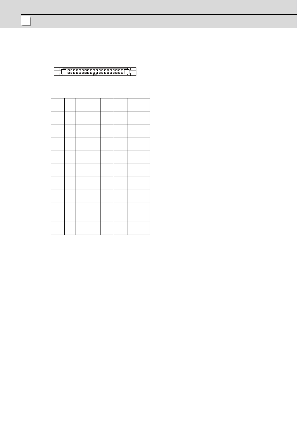
2 General Specifications
MITSUBISHI CNC
(5) Machine output (CF33)
B1 B20
A1 A20
Digital output
20 O Y40 20 O Y50
19 O Y41 19 O Y51
18 O Y42 18 O Y52
17 O Y43 17 O Y53
16 O Y44 16 O Y54
15 O Y45 15 O Y55
14 O Y46 14 O Y56
13 O Y47 13 O Y57
12 O Y48 12 O Y58
11 O Y49 11 O Y59
10 O Y4A 10 O Y5A
9O Y4B 9 O Y5B
8O Y4C 8 O Y5C
7O Y4D 7 O Y5D
6O Y4E 6 O Y5E
5O Y4F 5 O Y5F
44
33
2 I 24VDC 2 0V(RG)
1 I 24VDC 1 0V(RG)
CF33
BA
<Cable side connector type>
Connector: 7940-6500SC
Relief: 3448-7940
Recommended manufacturer: Sumitomo 3M
* This is an example when SCAN1 is set to "0", SCAN2 to "1", and DIO to "2".
Refer to "PLC Interface Manual" for details.
60
Page 83

M700VS Series Connection Manual
2.7 Scan I/O Unit
The HR357 output circuit is a source type (source output).
RA
PL
R
0V(RG)
FCU6-HR3
7
CF33
(Machine side)
Control
circuit
Source type
24VDC
CAUTION
1. Do not apply any voltage to the connector other than that specified in this manual. Fa ilure
to observe this could cause bursting, damage, etc.
Output conditions
Insulation method Non-insulation
Rated load voltage 24VDC
Max. output current 60mA/point
Saturation voltage 1.6V (standard)
Output delay time 40μs
(Note 1) When using an inductive load such as a relay, always connect a diode (voltage resistance 100V
or more, 100mA or more) in parallel to the load.
(Note 2) When using a capacitive load such as a lamp, always connect a protective resistor (R=150Ω)
serially to the load to suppress rush currents. (Make sure that the current is less than the
above tolerable current including the momentary current.)
61
Page 84

2 General Specifications
MITSUBISHI CNC
(6) 24VDC input (DCIN)
13
13
1 I+24V
2 0V
3 FG
<Cable side connector type>
Connector: 2-178288-3
Contact: 1-175218-5 x3
Recommended manufacturer: Tyco Electronics AMP
(7) Remote I/O unit I/F (RIO3A)
(8) Remote I/O unit I/F (RIO3B)
1 I/O TXRX1
2 I/O TXRX1*
3 0V
<Cable side connector type>
Connector: 1-178288-3
Contact: 1-175218-2 x3
Recommended manufacturer: Tyco Electronics AMP
62
Page 85

M700VS Series Connection Manual
2.8 External Power Supply Unit
2.8 External Power Supply Unit
Item PD25
Input power voltage
Output current 3A
Dimension 130mm × 65mm × 230mm
Mass 1.5kg
Output holding time 300ms
(Note) PD25 will not be turned ON by the ON/OFF switch immediately after the power OFF. Wait at least 2
seconds, and then turn the power ON.
Dimension and names of parts
[PD25]
65
200 to 230VAC
+10%-15%
50/60Hz±1Hz
230
220
6
AC IN
ON/OFF SW
ON/OFF
FAN ALARM
POWER
DC OUT
2-R3
30
(1)
(2)
(3)
(4)
(5)
6
130
208
230
<Mounting direction and clearance>
Mount the external power supply unit vertically and so that it is visible from the front. Provide space for heat
dissipation and ventilation.
100mm
20mm 20mm
100mm
63
Page 86

2 General Specifications
MITSUBISHI CNC
(1) AC power input (ACIN)
123
15
1 IACIN N
2 IACIN H
3 FG
<Cable side connector type>
Connector: 2-178128-3
Contact: 1-175218-5 × 3
Recommended manufacturer: Tyco Electronics AMP
(2) ON/OFF switch (ON/OFF SW)
Switch ON (upward): 24VDC output
Switch OFF (downward): 24VDC output OFF
(3) ON/OFF input (ON/OFF)
1 NC
2 IP-OFF
3 0V
4 0V
5 IP-ON
<Cable side connector type>
Connector: 1-178288-5
Contact: 1-175218-5 × 4
Recommended manufacturer: Tyco Electronics AMP
(4) LED (POWER)
Green light at +24V output
64
Page 87

M700VS Series Connection Manual
2.8 External Power Supply Unit
(5) 24VDC output (DCOUT)
A3A1
B3B1
1A OACFAIL 1B O +24V
2A 0V 2B 0V
3A NC 3B FG
<Cable side connector type>
Connector: 3-178127-6
Contact: 1-175218-5 (for AWG16) × 3, 1-175217-5 (for AWG22) × 2
Recommended manufacturer: Tyco Electronics AMP
65
Page 88

2 General Specifications
MITSUBISHI CNC
2.9 Manual Pulse Generator
3- M4Gasket
Above size only
72 at equal pitch
Panel cut diameter
stud
Index
<Panel cut drawing>
at equal pitch
<Outline dimension drawing>
[UFO-01-2Z9]
5V Manual Pulse Generator (100 pulse/rev)
Produced by NIDEC NEMICON CORPORATION
(Note) This product does not comply with the MITSUBISHI CNC standard.
66
Page 89
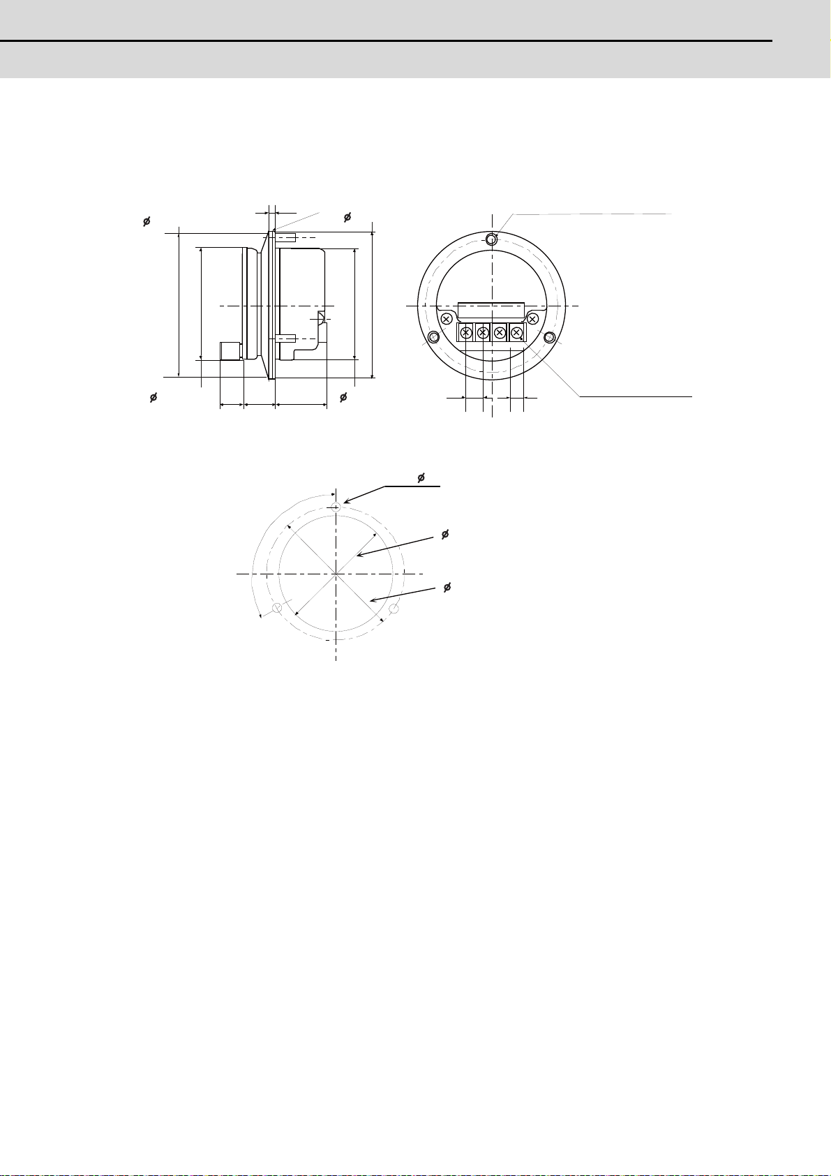
M700VS Series Connection Manual
2.9 Manual Pulse Generator
[HD60]
3. 6
16 24 27± 0. 5
77 ± 0. 5
80 ± 1
60 ± 0. 560 ± 0. 5
ޓL10
8. 8 9 7. 6 0
12V 0V A B
t2.0
3-M4
Installation of screws
stud bolt
Packing
other than M3 x 6
not possible
<Outline dimension drawing>
(Divide equally
by three)
<Panel cut dimension drawing>
12V Manual Pulse Generator (25 pulse/rev)
67
Page 90

2 General Specifications
MITSUBISHI CNC
2.10 Synchronous Feed Encoder
19. 5
102
135
5
3
33
2
68
28
20
56
68
4- 5.4
21m
m
14. 3
0
-0. 11
1. 1 5
+0. 14
0
1. 1 5
+0. 14
0
2
26
16
50
15
-0. 006
-0. 017
-0. 009
-0. 025
2
5
-0.012
-0.042
3
+
0
.
1
0
6
8
5
6
50
-
0
.
0
0
9
-
0
.
0
2
5
Caution plate
hole
Enlarged drawing of key
Valid depth of key groove is
Cross section BB
F
J
T
G
L
K
M
H
C
D
E
R
S
P
N
B
A
Dimension and names of parts
[OSE-1024-3-15-68]
68
Pin Function Pin Function
A A phase K 0V
B Z phase L C B phase M D - N A phase
E Case grounding P Z phase
F - R B phase
G - S H +5V T -
J -
Connector pin assignment
Page 91

M700VS Series Connection Manual
2.11 Optical Communication Repeater Unit (FCU7-EX022)
2.11 Optical Communication Repeater Unit (FCU7-EX022)
CAUTION
634
135
40
5
156
66
168
DCIN
ACFAIL
OPT1IN
DCOUT
FG
FUSE
OPT2IN
OPT1OUT
OPT2OUT
2-M5-0.8 screw
When the distance of the optical communication cable between NC control unit and drive unit is over 30m, the
communication can be performed by relaying the optical signal.
Using up to two units, relay of the total length of up to 90m can be performed.
<Product features>
(a) When the distance of the optical communication cable between NC control unit and drive unit is over 30m, the
communication can be performed by relaying the optical signal.
(b) The relay between NC control unit and drive unit can be performed for up to two systems.
(c) If the distance between NC control unit and drive unit is even within 30m, the cable can be divided by the relay in
transporting the machine.
(d) Same mounting dimension as the remote I/O unit (DX unit).
This unit cannot be used between drive units.
Dimension and Names of parts
69
Page 92

2 General Specifications
MITSUBISHI CNC
(1) Optical communication I/F (OPT1in, OPT1out, OPT2in, OPT2out)
13
A3A1
B3B1
<Cable side connector type>
(PCF type)
Connector : CF-2D101-S
Recommended manufacturer: Japan Aviation Electronics
(POF type)
Connector :PF-2D101
Recommended manufacturer: Japan Aviation Electronics
(2) DC24V input (DCIN)
1 I DC24V
2 0V(RG)
3 FG
<PCB side connector type>
Connector: 2-178293-5
Recommended manufacturer: Tyco Electronics AMP
<Cable side connector type>
Connector: 2-178288-3
Contact: 1-175218-5
Recommended manufacturer: Tyco Electronics AMP
(3) DC24V output (DCOUT)
A1 OACFAIL B1 O DC24V
A2 COM B2 0V(RG)
A3 NC B3 FG
<PCB side connector type>
Connector : 3-178137-5
Recommended manufacturer: Tyco Electronics AMP
<Cable side connector type>
Connector: 2-178127-6
Contact: 1-175218-5
Recommended manufacturer: Tyco Electronics AMP
70
Page 93

M700VS Series Connection Manual
2.11 Optical Communication Repeater Unit (FCU7-EX022)
(4) Power OFF input (CF01)
21
FG
Φ2.0
5.0
6.2
0.9
0.80.025
9.6
1 COM
2 IACFAIL
<PCB side connector type>
Connector: 53103-0230
Recommended manufacturer: MOLEX
<Cable side connector type>
connector: 51030-0230
Contact: 50084-8160
Recommended manufacturer: MOLEX
(5) FG terminal (FG)
<Cable side faston terminal type name>
Type name : 175022-1(For AWG20-14 250 series)
Recommended manufacturer: Tyco Electronics AMP
Terminal protection tube: 174817-2 (Yellow)
Unit side tab terminal shape
(Note) The faston terminal "175022-1" of the cable side is a simple lock type. Make sure to insert until the
simple lock pin is in the Φsecond hole. Firmly press the simple lock release tab when unplugging it.
71
Page 94

2 General Specifications
MITSUBISHI CNC
2.12 MITSUBISHI CNC Machine Operation Panel
2.12.1 MITSUBISHI CNC Machine Operation Panel A
Outline dimension
[FCU7-KB921 (MITSUBISHI CNC machine operation panel A)]
260
140
60
(Space required for wiring)
17
<Panel cut dimension drawing>
0.3
130
(Unit outline)
140
4-M3
Screw
260
(Square hole)
244
(Unit outline)
250
0.3
124
72
Page 95

M700VS Series Connection Manual
2.12 MITSUBISHI CNC Machine Operation Panel
Connector
(1)
(2)
(3)
(4)
(5)
(6)
13
No. Connector name Function No. Connector name Function
(1) DCIN DC24V input (4) FG FG terminal
(2) DCOUT DC24V output (5) EXT Relay wiring
(3) RIOIN Remote I/O (6) SUBP
Mahine operation panel B
switch
(1)(2) DC24V input/output (DCIN/DCOUT)
1 I/O DC24V
2 -0V
3 -FG
<Cable side connector type>
Connector: 2-178288-3
Contact: 1-175218-5 x3
Recommended manufacturer: Tyco Electronics AMP
73
Page 96

2 General Specifications
MITSUBISHI CNC
(3) Remote I/O connected connector (RIOIN)
13
1 I/O TX/RX
2 I/O TX*/RX*
3 -0V
<Cable side connector type>
Connector: 1-178288-3
Contact: 1-175218-2 x3
Recommended manufacturer: Tyco Electronics AMP
(4) FG terminal (FG)
(5) Relay wiring (EXT)
A5
B5
B05 - A05 B04 O Relay EMGCOM A04 O Relay EMG
B03 O Relay 6 A03 O Relay 5
B02 O Relay 4 A02 O Relay 3
B01 O Relay 2 A03 O Relay 1
A1
B1
<Cable side connector type>
Connector: HIF3BA-10D-2.54C
Contact: HIF3-2428SC
Recommended manufacturer: Hirose Electric
74
Page 97

M700VS Series Connection Manual
2.12 MITSUBISHI CNC Machine Operation Panel
(6) Machine operation panel B switch (SUBP)
A1
B1
A20
B20
B20 I Relay EMGCOM A20 I Relay EMG
B19 I Relay 6 A19 I Relay 5
B18 I Relay 4 A18 I Relay 3
B17 I Relay 2 A17 I Relay 1
B16 - 0V A16 I Spare SW(X75)
B15 - 0V A15 I Spare SW(X74)
B14 - 0V A14 I Spare SW(X73)
B13 - 0V A13 I Selector SW(X72)
B12 - A12 I G(X71)
B11 I F(X6D) A11 I E(X6F)
B10 I D(0V) A10 I C(X70)
B09 I B(X6E) A09 I A(X6C)
B08 - A08 I G(X6B)
B07 I F(X67) A07 I E(X66)
B06 I D(0V) A06 I C(X6A)
B05 I B(X68) A05 I A(X66)
B04 - A04 I G(X65)
B03 I F(X61) A03 I E(X63)
B02 I D(0V) A02 I C(X64)
B01 I B(X62) A01 I A(X60)
<Cable side connector type>
Connector: HIF3BA-40D-2.54C
Contact:HIF3-2428SC
Recommended manufacturer: Hirose Electric
75
Page 98

2 General Specifications
MITSUBISHI CNC
D
G
C
E
B
F
A
[SUBP]
X60
X61
X62
X63
X64
X65
X66
X67
X68
X69
X6A
X6B
B02
A01
B03
B01
A03
A02
A04
+5V
D
G
C
E
B
F
A
B06
A05
B07
B05
A07
A06
A08
+5V
(RSW2)
X6D
X6E
X6F
X70
X71
D
G
C
E
B
F
A
B10
A09
B11
B09
A11
A10
A12
+5V
1kΩ
X6C
21 position
(RSW1)
Machine Operation Panel
I/F PCB HN232
Machine operation panel B
(FCU7-KB926)
Rotary Switch
Real gray code
(For cutting override)
Rotary Switch
(For spindle override)
8 position
Real gray code
Rotary Switch
(Spare)
(a) Wiring of machine operation panel B
<Wiring of rotary switch (SUBP)>
(Note1) Use the special lead wire with a connector for wiring of rotary switch.
(Note2) A09 to 12 and B09 to 11 of SUBP are spares, so they do not need wiring.
(Note3) Select a rotary switch which guarantees 5V/1mA.
(Note4) Length of cables must be 0.5m or shorter.
(Note5) The numbers in the above diagram do not indicate the actual device numbers.
76
Lead wire with a connector: ACX011-705 (7 terminals, 0.5m) Fuji Electric
Page 99

M700VS Series Connection Manual
2.12 MITSUBISHI CNC Machine Operation Panel
<Wiring of other switches (SUBP)>
Machine Operation Panel
I/F PCB HN232
+5V
1kΩ
X72
X73
X74
[SUBP]
A13
B13
A14
B14
A15
B15
Machine operation panel B
(FCU7-KB926)
Selector Switch
(For memory protection)
2 notch Key shape
2c Manual return type
Switch input spare
(3 points)
A16
B16
A17
B17
A18
B18
A19
B19
A20
B20
Spare for signal relay
Push down switch
(For emergency stop)
Push Lock -
Turn Reset
2a2b contact
EMG
X75
[EXT]
A01
B01
A02
B02
A03
B03
A04
B04
A05
B05
(Note1) Wirings for selector switches must be directly soldered to terminals or use tab terminals (110
series).
(Note2) When wiring the emergency stop switch, the crimp terminal must be fastened with thread.
(Note3) For NCs whose control unit and display are integrated, wire the emergency stop switch directly
to the EMG connector of the control unit. (Use F120 cable)
And for NCs whose control unit and display are separated, relay it by the machine operation
panel I/F PCB HN232.
(Note4) Select a rotary switch which guarantees 5V/1mA.
(Note5) Length of cables must be 0.5m or shorter.
(Note6) The numbers in the above diagram do not indicate the actual device numbers.
77
Page 100

2 General Specifications
MITSUBISHI CNC
<Connection when the selector SW has 3 notches>
[SUBP]
X72
X73
X74
X75
B13
A13
A14
A15
A16
B14
B15
B16
+5V
Selector SW
3 notch
2a2b Manual return type
B20
A20
[EXT]
A17
B17
A18
B18
A19
B19
EMG
EMGCOM
(DC24V)
B04
A04
B01
A01
B02
A02
B03
A03
EMG
EMGCOM
(DC24V)
P-ON
P-OFF
PON
POF F
PON CO M
(0V)
POF FC OM
(0V)
A05
B05
Connection with
P-ON/OFF Switch
Connection using two contacts
of emergency switch
Push button SW
(For emergency stop)
Push Lock Turn Reset
2a2b contact
<Connection when relaying wiring to control panel>
78
 Loading...