

Page 1

Page 2

Page 3

MELDAS is a registered trademark of Mitsubishi Electric Corporation.
Other company and product names that appear in this manual are trademarks or registered
trademarks of the respective companies.
Page 4

Page 5

Introduction
This manual is a guide for using the MITSUBISHI CNC M700V/M70 Series.
Programming for M2/M0 format is described in this manual, so read this manual thoroughly
before starting programming. Thoroughly study the "Precautions for Safety" on the
following page to ensure safe use of this NC unit.
Details described in this manual
CAUTION
For items described in "Restrictions" or "Usable State", the instruction manual issued by the machine
tool builder takes precedence over this manual.
An effort has been made to note as many special handling methods in this user's manual. Items not
described in this manual must be interpreted as "not possible".
This manual has been written on the assumption that all option functions are added. Refer to the
specifications issued by the machine tool builder before starting use.
Refer to the Instruction Manual issued by each machine tool builder for details on each machine tool.
Some screens and functions may differ depending on the NC system or its version, and some
functions may not be possible. Please confirm the specifications before use.
General precautions
(1) Refer to the following documents for details on handling
MITSUBISHI CNC M700V/M70 Series Instruction Manual ......................... IB-1500922
Page 6

Page 7

Precautions for Safety
Always read the specifications issued by the machine maker, this manual, related manuals
and attached documents before installation, operation, programming, maintenance or
inspection to ensure correct use.
Understand this numerical controller, safety items and cautions before using the unit.
This manual ranks the safety precautions into "DANGER", "WARNING" and "CAUTION".
DANGER
WARNING
CAUTION
Note that even items ranked as " CAUTION", may lead to major results depending on the
situation. In any case, important information that must always be observed is described.
When the user may be subject to imminent fatalities or major injuries if
handling is mistaken.
When the user may be subject to fatalities or major injuries if handling is
mistaken.
When the user may be subject to injuries or when physical damage may
occur if handling is mistaken.
DANGER
Not applicable in this manual.
WARNING
1. Items related to operation
If the operation start position is set in a block which is in the middle of the program and the
program is started, the program before the set block is not executed. Please confirm that G
and F modal and coordinate values are appropriate. If there are coordinate system shift
commands or M, S, T and B commands before the block set as the start position, carry out
the required commands using the MDI, etc. If the program is run from the set block without
carrying out these operations, there is a danger of interference with the machine or of
machine operation at an unexpected speed, which may result in breakage of tools or
machine tool or may cause damage to the operators.
Under the constant surface speed control (during G96 modal), if the axis targeted for the
constant surface speed control moves toward the spindle center, the spindle rotation
speed will increase and may exceed the allowable speed of the workpiece or chuck, etc. In
this case, the workpiece, etc. may jump out during machining, which may result in
breakage of tools or machine tool or may cause damage to the operators.
Page 8

1. Items related to product and manual
For items described as "Restrictions" or "Usable State" in this manual, the instruction manual
issued by the machine tool builder takes precedence over this manual.
An effort has been made to describe special handling of this machine, but items that are not
described must be interpreted as "not possible".
This manual is written on the assumption that all option functions are added. Refer to the
specifications issued by the machine tool builder before starting use.
Refer to the Instruction Manual issued by each machine tool builder for details on each
machine tool.
Some screens and functions may differ depending on the NC system or its version, and some
functions may not be possible. Please confirm the specifications before use.
2. Items related to operation
Before starting actual machining, always carry out dry operation to confirm the machining
program, tool compensation amount and workpiece offset amount, etc.
If the workpiece coordinate system offset amount is changed during single block stop, the new
setting will be valid from the next block.
Turn the mirror image ON and OFF at the mirror image center.
Refer to the Instruction Manual issued by each machine tool builder for details on each
machine tool.
If the tool compensation amount is changed during automatic operation (including during single
block stop), it will be validated from the next block or blocks onwards.
CAUTION
3. Items related to programming
The commands with "no value after G" will be handled as "G00".
“EOB", "%", and “EOR” are symbols used for explanation. The actual codes for ISO are "CR,
LF" ("LF") and "%".
The programs created on the Edit screen are stored in the NC memory in a "CR, LF" format,
however, the programs created with external devices such as the FLD or RS-232C may be
stored in an "LF" format.
The actual codes for EIA are "EOB (End of Block)" and "EOR (End of Record)".
When creating the machining program, select the appropriate machining conditions, and make
sure that the performance, capacity and limits of the machine and NC are not exceeded. The
examples do not consider the machining conditions.
Do not change fixed cycle programs without the prior approval of the machine tool builder.
When programming a program of the multi-part system, carefully observe the movements
caused by other part systems' programs.
Page 9

Disposal
(Note) This symbol mark is for EU countries only.
This symbol mark is according to the directive 2006/66/EC Article 20 Information for endusers and Annex II.
Your MITSUBISHI ELECTRIC product is designed and manufactured with high quality materials and
components which can be recycled and/or reused.
This symbol means that batteries and accumulators, at their end-of-life, should be disposed of
separately from your household waste.
If a chemical symbol is printed beneath the symbol shown above, this chemical symbol means that the
battery or accumulator contains a heavy metal at a certain concentration. This will be indicated as
follows:
Hg: mercury (0,0005%), Cd: cadmium (0,002%), Pb: lead (0,004%)
In the European Union there are separate collection systems for used batteries and accumulators.
Please, dispose of batteries and accumulators correctly at your local community waste collection/
recycling centre.
Please, help us to conserve the environment we live in!
Page 10

Page 11

Contents
1. Control Axes..................................................................................................................................1
1.1 Coordinate Words and Control Axis........................................................................................1
1.2 Coordinate Systems and Coordinate Zero Point Symbols......................................................2
2. Least Command Increments........................................................................................................3
2.1 Input Setting Units...................................................................................................................3
2.2 Input Command Increment Tenfold.........................................................................................5
2.3 Indexing Increment..................................................................................................................6
3. Data Formats.................................................................................................................................7
3.1 Tape Codes.............................................................................................................................7
3.2 Program Formats ..................................................................................................................10
3.3 Tape Memory Format............................................................................................................13
3.4 Optional Block Skip ............................................................................................................... 13
3.4.1 Optional Block Skip ; /.....................................................................................................13
3.4.2 Optional Block Skip Addition ; /n ....................................................................................14
3.5 Program/Sequence/Block Numbers ; L(O), N .......................................................................16
3.6 Parity H/V ..............................................................................................................................17
3.7 G Code Lists ......................................................................................................................... 18
3.8 Precautions Before Starting Machining................................................................................. 21
4. Buffer Register............................................................................................................................22
4.1 Input Buffer............................................................................................................................22
4.2 Pre-read Buffers....................................................................................................................23
5. Position Commands ...................................................................................................................24
5.1 Position Command Methods ; G90, G91 ..............................................................................24
5.2 Inch/Metric Command Change; G20, G21............................................................................26
5.3 Decimal Point Input ...............................................................................................................28
6. Interpolation Functions..............................................................................................................33
6.1 Positioning (Rapid Traverse); G00........................................................................................33
6.2 Linear Interpolation; G01.......................................................................................................40
6.3 Plane Selection; G17, G18, G19...........................................................................................42
6.4 Circular Interpolation; G02, G03 ...........................................................................................44
6.5 R-specified Circular Interpolation; G02, G03 ........................................................................49
6.6 Helical Interpolation ; G17 to G19, G02, G03 .......................................................................52
6.7 Thread Cutting ...................................................................................................................... 56
6.7.1 Constant Lead Thread Cutting; G33............................................................................... 56
6.7.2 Inch Thread Cutting; G33................................................................................................60
6.8 Unidirectional Positioning; G60 ............................................................................................. 61
6.9 Cylindrical Interpolation; G07.1 .............................................................................................63
6.10 Polar Coordinate Interpolation; G12.1, G13.1.....................................................................71
6.11 Exponential Function Interpolation; G02.3, G03.3 ..............................................................78
6.12 Polar Coordinate Command; G16/G15 ...............................................................................84
6.13 Spiral/Conical Interpolation; G02.0/G03.1(Type1), G02/G03(Type2) .................................90
6.14 3-dimensional Circular Interpolation; G02.4, G03.4 ............................................................ 95
6.15 NURBS Interpolation.........................................................................................................100
6.16 Hypothetical Axis Interpolation; G07 ................................................................................. 105
7. Feed Functions .........................................................................................................................107
7.1 Rapid Traverse Rate ...........................................................................................................107
7.2 Cutting Feedrate ................................................................................................................. 107
7.3 F1-digit Feed ....................................................................................................................... 108
7.4 Per-minute/Per-revolution Feed (Asynchronous/Synchronous Feed); G94, G95 ...............110
Page 12

7.5 Inverse Time Feed; G93 .....................................................................................................112
7.6 Feedrate Designation and Effects on Control Axes ............................................................116
7.7 Rapid Traverse Constant Inclination Acceleration/Deceleration......................................... 120
7.8 Rapid Traverse Constant Inclination Multi-step Acceleration/Deceleration ........................122
7.9 Exact Stop Check; G09.......................................................................................................131
7.10 Exact Stop Check Mode; G61...........................................................................................134
7.11 Deceleration Check...........................................................................................................134
7.11.1 G1 -> G0 Deceleration Check.....................................................................................136
7.11.2 G1 -> G1 Deceleration Check.....................................................................................137
7.12 Automatic Corner Override ...............................................................................................138
7.13 Tapping Mode; G63 ..........................................................................................................143
7.14 Cutting Mode; G64 ............................................................................................................143
8. Dwell...........................................................................................................................................144
8.1 Per-second Dwell ; G04 ......................................................................................................144
9. Miscellaneous Functions .........................................................................................................146
9.1 Miscellaneous Functions (M8-digits BCD) ..........................................................................146
9.2 Secondary Miscellaneous Functions (B8-digits, A8 or C8-digits) .......................................148
9.3 Index Table Indexing...........................................................................................................149
10. Spindle Functions...................................................................................................................151
10.1 Spindle Functions (S6-digits Analog)................................................................................ 151
10.2 Spindle Functions (S8-digits) ............................................................................................151
10.3 Constant Surface Speed Control; G96, G97.....................................................................152
10.4 Spindle Clamp Speed Setting; G92 ..................................................................................154
10.5 Spindle/C Axis Control ......................................................................................................156
10.6 Multiple Spindle Control ....................................................................................................159
10.6.1 Multiple Spindle Control II........................................................................................... 160
11. Tool Functions (T command).................................................................................................162
11.1 Tool Functions (T8-digit BCD)...........................................................................................162
12. Tool Compensation Functions ..............................................................................................163
12.1 Tool Compensation ...........................................................................................................163
12.2 Tool Length Compensation/Cancel; G43/G44 ..................................................................167
12.3 Tool Length Compensation in the Tool Axis Direction ; G43.1/G44..................................170
12.4 Tool Radius Compensation; G38, G39/G40/G41,G42......................................................177
12.4.1 Tool Radius Compensation Operation........................................................................ 178
12.4.2 Other Commands and Operations During Tool Radius Compensation ......................187
12.4.3 G41/G42 Commands and I, J, K Designation............................................................. 196
12.4.4 Interrupts During Tool Radius Compensation............................................................. 202
12.4.5 General Precautions for Tool Radius Compensation..................................................204
12.4.6 Changing of Compensation No. During Compensation Mode .................................... 205
12.4.7 Start of Tool Radius Compensation and Z Axis Cut in Operation............................... 207
12.4.8 Interference Check .....................................................................................................209
12.4.9 Diameter Designation of Compensation Amount........................................................ 216
12.4.10 Workpiece Coordinate Changing During Radius Compensation.............................. 218
12.5 Three-dimensional Tool Radius Compensation ; G40/G41,G42.......................................220
12.6 Tool Position Offset; G45 to G48 ......................................................................................231
12.7 Programmed Compensation Input; G10, G11.1................................................................238
12.8 Compensation Data Input to Variable by Program; G11...................................................243
12.9 Inputting the Tool Life Management Data; G10, G11 .......................................................244
12.9.1 Inputting the Tool Life Management Data by G10 L3 Command................................244
12.9.2 Inputting the Tool Life Management Data by G10 L30 Command..............................246
12.9.3 Precautions for Inputting the Tool Life Management Data..........................................249
Page 13

13. Program Support Functions ..................................................................................................250
13.1 Fixed Cycles......................................................................................................................250
13.1.1 Standard Fixed Cycles; G80 to G89, G73, G74, G75, G76 ........................................250
13.1.2 Drilling Cycle with High-Speed Retract....................................................................... 278
13.1.3 Initial Point and R Point Level Return; G98, G99........................................................281
13.1.4 Setting of Workpiece Coordinates in Fixed Cycle Mode............................................. 283
13.2 Special Fixed Cycle; G34, G35, G36, G37 .......................................................................284
13.3 Subprogram Control; G22, G22 ........................................................................................289
13.3.1 Calling Subprogram with G22 and G22 Commands...................................................289
13.3.2 Figure Rotation; G22 I_ J_ K_ .................................................................................... 293
13.4 Variable Commands..........................................................................................................296
13.5 User Macro Specifications ................................................................................................301
13.5.1 User Macro Commands; G65, G66, G66.1, G67, G68(G23)......................................301
13.5.2 Macro Call Command .................................................................................................302
13.5.3 ASCII Code Macro ...................................................................................................... 311
13.5.4 Variables.....................................................................................................................315
13.5.5 Types of Variables ......................................................................................................317
13.5.6 Arithmetic Commands.................................................................................................355
13.5.7 Control Commands ..................................................................................................... 360
13.5.8 External Output Commands........................................................................................363
13.5.9 Precautions.................................................................................................................365
13.5.10 Actual Examples of Using User Macros....................................................................367
13.6 G Command Mirror Image; G50.1, G51.1 / G62 ...............................................................371
13.7 Corner Chamfering/Corner Rounding I .............................................................................374
13.7.1 Corner Chamfering " ,C_ " ..........................................................................................374
13.7.2 Corner Rounding " ,R_ " .............................................................................................376
13.8 Linear Angle Command ....................................................................................................377
13.9 Geometric Command ........................................................................................................378
13.10 Circle Cutting; G12, G13 ................................................................................................. 382
13.11 Parameter Input by Program; G10, G11.1 ......................................................................384
13.12 Macro Interrupt; ION, IOF ...............................................................................................385
13.13 Tool Change Position Return; G30.1 to G30.6 ...............................................................393
13.14 Normal Line Control ; G40.1/G41.1/G42.1......................................................................396
13.15 High-accuracy Control ; G61.1, G08 ...............................................................................407
13.16 High-speed Machining Mode; G05, G05.1......................................................................421
13.16.1 High-speed Machining Mode I,II; G05 P1, G05 P2................................................... 421
13.17 High-speed High-accuracy Control; G05, G05.1.............................................................424
13.17.1 High-speed High-accuracy Control I, II..................................................................... 424
13.17.2 SSS Control ..............................................................................................................430
13.18 Spline; G05.1 .................................................................................................................. 435
13.19 High-accuracy Spline Interpolation ; G61.2.....................................................................442
13.20 Scaling; G50/G51............................................................................................................444
13.21 Coordinate Rotation by Program; G68.1/G69.1 ..............................................................449
13.22 Coordinate Rotation Input by Parameter; G10................................................................457
13.23 3-dimensional Coordinate Conversion; G68.1/69.1 ........................................................460
13.24 Tool Center Point Control; G43.4/G43.5 .........................................................................477
13.25 Timing-synchronization between Part Systems ..............................................................499
13.26 End Point Error Check Cancellation; G69.......................................................................502
13.27 Coordinate Read Function; G14 .....................................................................................504
14. Coordinates System Setting Functions................................................................................507
14.1 Coordinate Words and Control Axes.................................................................................507
14.2 Basic Machine, Workpiece and Local Coordinate Systems..............................................508
14.3 Machine Zero Point and 2nd, 3rd, 4th Reference Positions..............................................509
14.4 Basic Machine Coordinate System Selection; G53...........................................................510
Page 14

14.5 Coordinate System Setting; G92.......................................................................................511
14.6 Automatic Coordinate System Setting ..............................................................................512
14.7 Reference (Zero) Position Return; G28, G29....................................................................513
14.8 2nd, 3rd and 4th Reference (Zero) Position Return; G30 .................................................517
14.9 Reference Position Check; G27........................................................................................ 520
14.10 Workpiece Coordinate System Setting and Offset ; G54 to G59 (G54.1) .......................521
14.11 Local Coordinate System Setting; G52 ...........................................................................533
14.12 Workpiece Coordinate System Preset; G92.1 ................................................................537
14.13 Coordinate System for Rotary Axis .................................................................................542
15. Measurement Support Functions..........................................................................................545
15.1 Automatic Tool Length Measurement; G37.1 ...................................................................545
15.2 Skip Function; G31............................................................................................................549
15.3 Multi-step Skip Function; G31.n, G04 ...............................................................................554
15.4 Multi-step Skip Function 2; G31........................................................................................ 556
15.5 Speed Change Skip; G31 .................................................................................................558
15.6 Programmable Current Limitation .....................................................................................561
15.7 Stroke Check Before Travel; G22.1/G23.1 .......................................................................562
Appendix 1. Program Error .......................................................................................................564
Appendix 2. Order of G Function Command Priority..............................................................584
Page 15

1. Control Axes
f
f
P
f
Di
1. Control Axes
1.1 Coordinate Words and Control Axis
Function and purpose
In the standard specifications, there are 3 control axes, but, by adding an additional axis, up to 4
axes can be controlled.
The designation of the processing direction responds to those axes and uses a coordinate word
made up of alphabet characters that have been decided beforehand.
X-Y table
+Z
+Y
+X
Program coordinates
Workpiece
1.1 Coordinate Words and Control Axis
+Z
X-Y table
+Y
Direction o
table movement
Bed
+X
Direction o
table movement
X-Y and revolving table
+Z
+Y
+C
+X
rogram coordinates
+X
Direction o
movement
table
+Y
Workpiece
+C
rection of table
revolution
1
Page 16
1. Control Axes
Machi
1
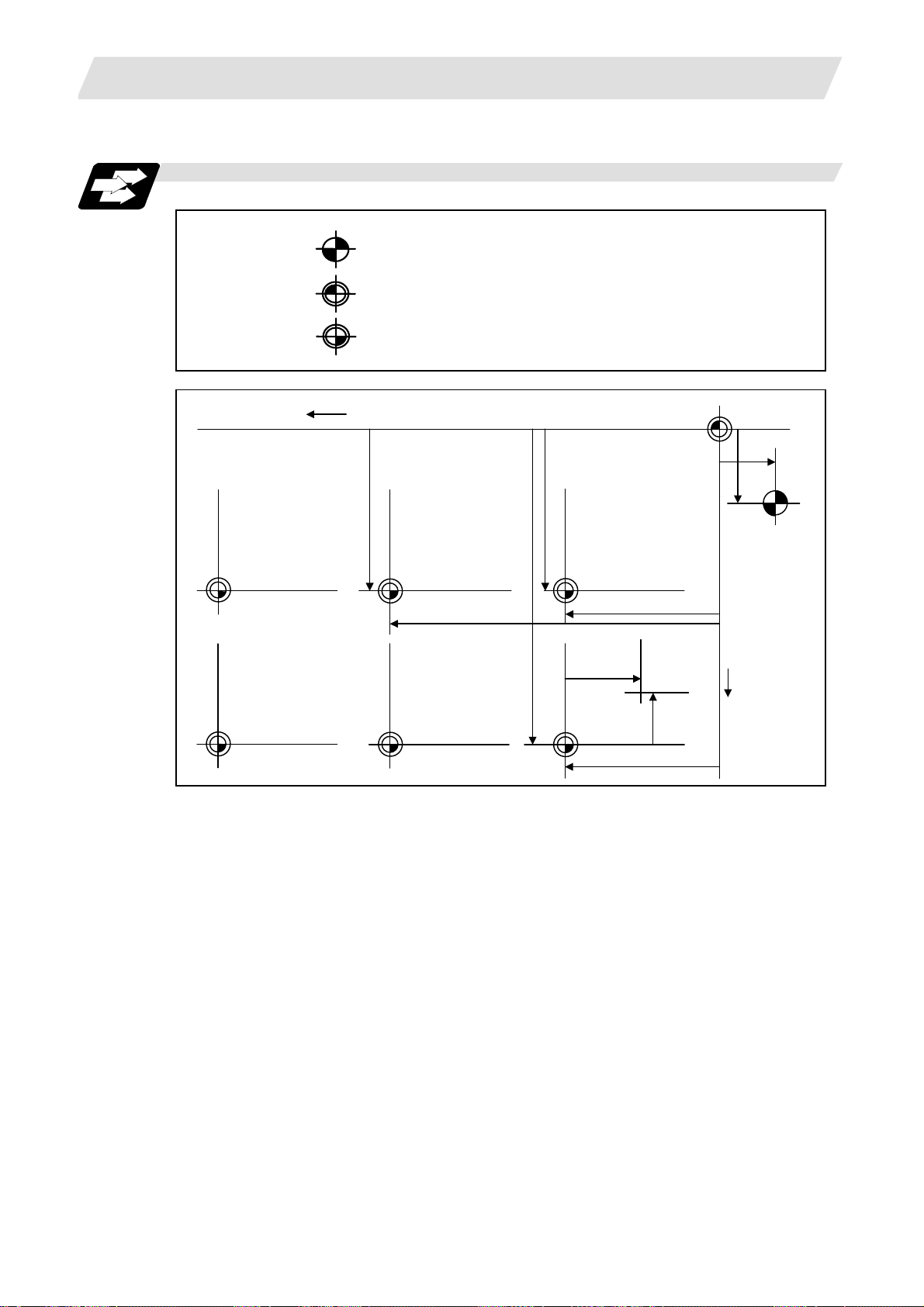
1.2 Coordinate Systems and Coordinate Zero Point Symbols
1.2 Coordinate Systems and Coordinate Zero Point Symbols
Function and purpose
Workpiece
coordinate
system 3 (G56)
-X
: Reference position
: Machine coordinate zero point
: Workpiece coordinate zero points (G54 - G59)
Basic machine coordinate system
y
3
Workpiece
coordinate
system 2 (G55)
y
2
Workpiece
coordinate
system 1 (G54)
zero point
x1
y1
st reference
position
ne
x
2
Local
coordinate
x
5
system
(G52)
y
-Y
x
Workpiece
coordinate
system 6 (G59)
x
3
Workpiece
coordinate
system 5 (G58)
y
5
Workpiece
coordinate
system 4
(G57)
2
Page 17
2. Least Command Increments
2. Least Command Increments
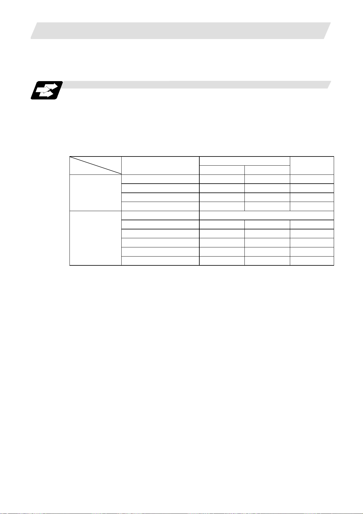
2.1 Input Setting Units
Function and purpose
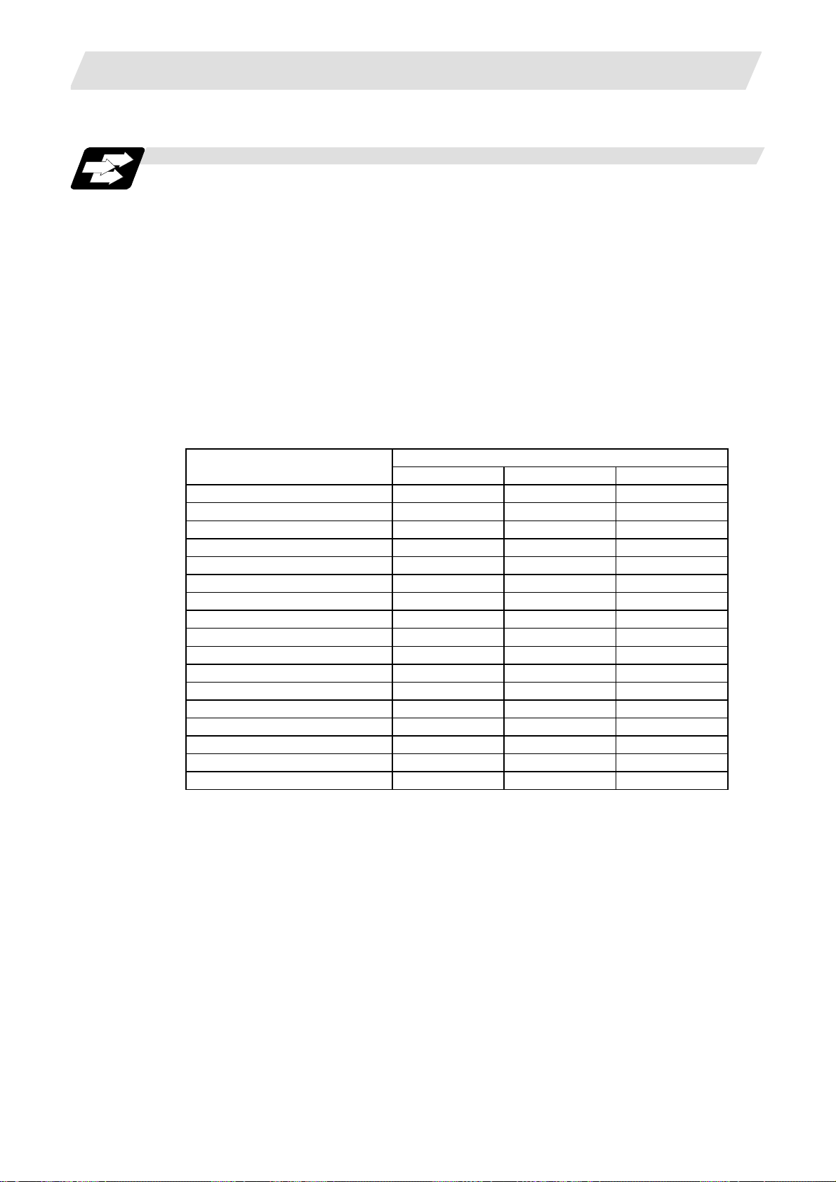
The input setting units are, as with the compensation amounts, the units of setting data used in
common for all axes.
The command units are the movement amounts in the program which are commanded with MDI
inputs or command tape. These are expressed with mm, inch or degree (°) units.
With the parameters, the command units are decided for each axis, and the input setting units are
decided commonly for all axes.
#1003 iunit = B
Input setting unit
Command unit
(Note 1) Inch/metric changeover is performed in either of 2 ways: conversion from the parameter
screen (#1041 I_inch: valid only when the power is turned ON) and conversion using the
G command (G20 or G21).
However, when a G command is used for the conversion, the conversion applies only to
the input command increments and not to the input setting units.
Consequently, the tool offset amounts and other compensation amounts as well as the
variable data should be preset to correspond to inches or millimeters.
(Note 2) The millimeter and inch systems cannot be used together.
(Note 3) During circular interpolation on an axis where the input command increments are
different, the center command (I, J, K) and the radius command (R) can be designated by
the input setting units. (Use a decimal point to avoid confusion.)
= C
= D
= E
#1015 cunit = 0 Follow #1003 iunit
= 1
= 10
= 100
= 1000
= 10000
Parameters
2.1 Input Setting Units
Linear axis
Millimeter Inch
0.001 0.0001 0.001
0.0001 0.00001 0.0001
0.00001 0.000001 0.00001
0.000001 0.0000001 0.000001
0.0001 0.00001 0.0001
0.001 0.0001 0.001
0.01 0.001 0.01
0.1 0.01 0.1
1.0 0.1 1.0
Rotation axis
(°)
3
Page 18
2. Least Command Increments
Detailed description
(1) Units of various data
These input setting units determine the parameter setting unit, program command unit and the
external interface unit for the PLC axis and handle pulse, etc. The following rules show how the
unit of each data changes when the input setting unit is changed. This table applies to the NC
axis and PLC axis.
2.1 Input Setting Units
Data
Speed data
Example:
rapid
Position data
Example:
SoftLimit+
Interpolation
unit data
Unit
system
metre
Inch
metre
Inch
metre
Inch
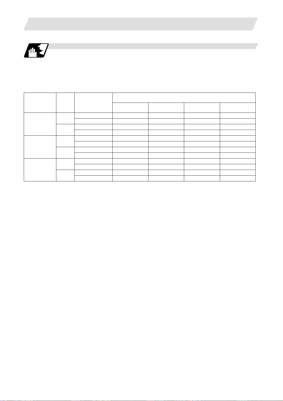
(2) Program command
The program command unit follows the above table.
If the data has a decimal point, the number of digits in the integer section will remain and the
number of digits in the decimal point section will increase as the input setting unit becomes
smaller.
When setting data with no decimal point, and which is a position command, the data will be
affected by the input setting increment and input command increment.
For the feed rate, as the input setting unit becomes smaller, the number of digits in the integer
section will remain the same, but the number of digits in the decimal point section will increase.
Setting value
1µm (B) 0.1µm (C) 10nm (D) 1nm (E)
20000 (mm/min) 20000 20000 20000 20000Milli-
Setting range 1 to 999999 1 to 999999 1 to 999999 1 to 999999
2000 (inch/min) 2000 2000 2000 2000
Setting range 1 to 999999 1 to 999999 1 to 999999 1 to 999999
123.123 (mm) 123.123 123.1230 123.12300 123.123000MilliSetting range ±99999.999 ±99999.9999 ±99999.99999 ±99999.999999
12.1234 (inch) 12.1234 12.12340 12.123400 12.1234000
Setting range ±9999.9999 ±9999.99999 ±9999.999999 ±9999.9999999
1 (µm) 2 20 200 2000Milli-
Setting range ±9999 ±9999 ±9999 ±9999
0.001 (inch) 2 20 200 2000
Setting range ±9999 ±9999 ±9999 ±9999
Input setting unit
4
Page 19
2. Least Command Increments
2.2 Input Command Increment Tenfold
Function and purpose
The program's command increment can be multiplied by an arbitrary scale with the parameter
designation.
This function is valid when a decimal point is not used for the command increment.
The scale is set with the parameters.
Detailed description
(1) When running a machining program already created with a 10µm input command increment
with a CNC unit for which the command increment is set to 1µm and this function's parameter
value is set to "10", machining similar to before this function is possible.
(2) When running a machining program already created with a 1µm input command increment
with a CNC unit for which the command increment is set to 0.1µm and this function's
parameter value is set to "10", machining similar to before this function is possible.
(3) This function cannot be used for the dwell function G04_X_(P_);.
(4) This function cannot be used for the compensation amount of the tool compensation input.
(5) This function can be used when decimal point type I is valid, but cannot be used when decimal
point type II is valid.
Program example
(Machining program:
programmed with 1=10µm)
(CNC unit is 1=1µm system)
X Y X Y
N1 G90 G00 X0 Y0; 0 0 0 0
N2 G91 X-10000 Y-15000; -100.000 -150.000 -10.000 -15.000
N3 G01 X-10000 Y-5000 F500; -200.000 -200.000 -20.000 -20.000
N4 G03 X-10000 Y-10000 J-10000; -300.000 -300.000 -30.000 -30.000
N5 X10000 Y-10000 R5000; -200.000 -400.000 -20.000 -40.000
N6 G01 X20.000 Y.20.000 -180.000 -380.000 0.000 -20.000
2.2 Input Command Increment Tenfold
"UNIT*10" parameter
10 1
N4
N5
R
-100 -200 -300
N3
N6
UNIT*10 ON
N1
N2
W
-100
-200
-300
-400
N4
N5
R
-10 -20 -30
N3
UNIT*10 OFF
N1
N6
N2
W
-10
-20
-30
-40
5
Page 20
2. Least Command Increments
2.3 Indexing Increment
Function and purpose
This function limits the command value for the rotary axis.
This can be used for indexing the rotary table, etc. It is possible to cause a program error with a
program command other than an indexing increment (parameter setting value).
Detailed description
When the indexing increment (parameter) for limiting the command value is set, the rotary axis can
be positioned with that indexing increment. If a program other than the indexing increment setting
value is commanded, a program error (P20) will occur.
The indexing position will not be checked when the parameter is set to 0.
(Example) When the indexing increment setting value is 2 degrees, only command with the
2-degree increment are possible.
G90 G01 C102. 000 ; … Moves to the 102 degree angle.
G90 G01 C101. 000 : … Program error
G90 G01 C102 ; … Moves to the 102 degree angle. (Decimal point type II)
The following axis specification parameter is used.
# Item Contents
2106 Index unit Indexing
Precautions
• When the indexing increment is set, degree increment positioning takes place.
• The indexing position is checked with the rotary axis, and is not checked with other axes.
• When the indexing increment is set to 2 degrees, the rotary axis is set to the B axis, and the B
axis is moved with JOG to the 1.234 position, an indexing error will occur if "G90B5." or "G91B5."
is commanded.
increment
2.3 Indexing Increment
Set the indexing increment to which the rotary
axis can be positioned.
Setting range
(unit)
0 to 360 (° )
6
Page 21
3. Data Formats
3. Data Formats
3.1 Tape Codes
Function and purpose
The tape command codes used for this controller are combinations of alphabet letters (A, B, C, ...
Z), numbers (0, 1, 2 ... 9) and signs (+, -, / ...). These alphabet letters, numbers and signs are
referred to as characters. Each character is represented by a combination of 8 holes which may, or
may not, be present.
These combinations make up what is called codes.
This controller uses, the ISO code (R-840).
(Note 1) If a code not given in the tape code table in Fig. 1 is assigned during operation, program
(Note 2) For the sake of convenience, a semicolon " ; " has been used in the CNC display to
3.1 Tape Codes
error (P32) will result.
indicate the end of a block (EOB/IF) which separates one block from another. Do not use
the semicolon key, however, in actual programming but use the keys in the following
table instead.
CAUTION
“EOB", "%", and “EOR” are symbols used for explanation. The actual codes for
ISO are "CR, LF" ("LF") and "%".
The programs created on the Edit screen are stored in the NC memory in a "CR,
LF" format, however, the programs created with external devices such as the FLD
or RS-232C may be stored in an "LF" format.
The actual codes for EIA are "EOB (End of Block)" and "EOR (End of Record)".
Detailed description
EOB/EOR keys and displays
Key used
End of block LF or NL ;
End of record % %
(1) Significant data section (label skip function)
All data up to the first EOB ( ; ), after the power has been turned on or after operation has been
reset, are ignored during automatic operation based on tape, memory loading operation or
during a search operation. In other words, the significant data section of a tape extends from
the character or number code after the initial EOB ( ; ) code after resetting to the point where
the reset command is issued.
Code used
ISO Screen display
7
Page 22
3. Data Formats
G
R
•••••••
•
•••
•
•
•••••••••
•
•••••••
•
•
•••••••••••••••••
•
•
•
•••••••••••••••
•••••••••
•
(2) Control out, control in
All data between control out "(" and control in ")" or ";" , from "0" to ";" (when label L) are
ignored, although these data appear on the setting and display unit. Consequently, the
command tape name, No. and other such data not directly related to control can be inserted in
this section.
This information (except (B) in the tape codes) will also be loaded, however, during tape
loading. The system is set to the "control in" mode when the power is witched on.
Example of ISO code
•
3.1 Tape Codes
•
•• ••
• • • • • • • • • • • • • • • • • • • • • • • • • • • • • • • • • • • • • • • • • • • • • • • •
•••
•••
• •
• • •• •
Operator information print-out example
L C S L
00X- 85000Y-64000 (CUTTE
F R
• ••
•• •• •
••
••
•••
•••
•
•
Information in this section is ignored and nothing is executed.
RE T URN )
P
• •
•• •
•• • ••
•••
•
••••
• • • •
F
••
•••••
•
•
The difference of the label and variable code is the following tables.
Code Control in/out range Label (L) Label (O)
ISO/EIA Form "(" to ")" Ignore the data. Ignore the data.
From "O" to "; (EOB)" Ignore the data. The value after "O" will be
handled as label No.
(Note) Always set "O" at the head of the block. A program error (P32) will occur if there is "O"
besides the head of the block.
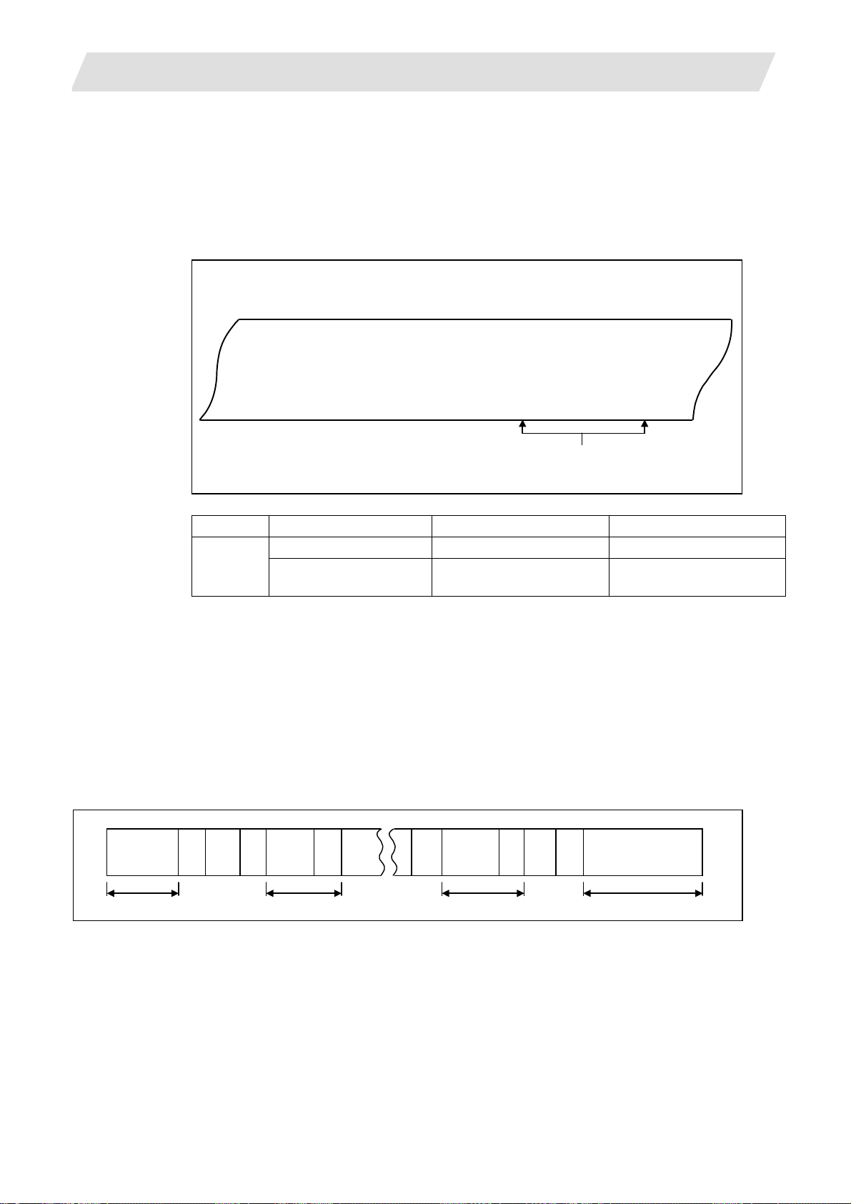
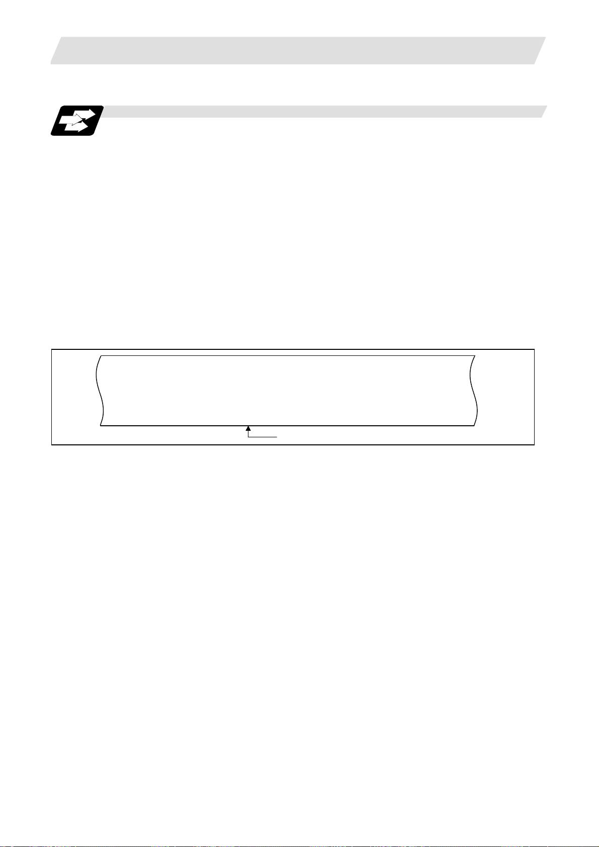
(3) EOR (%) code
Generally, the end-or-record code is punched at both ends of the tape. It has the following
functions:
(a) Rewind stop when rewinding tape (with tape handler)
(b) Rewind start during tape search (with tape handler)
(c) Completion of loading during tape loading into memory
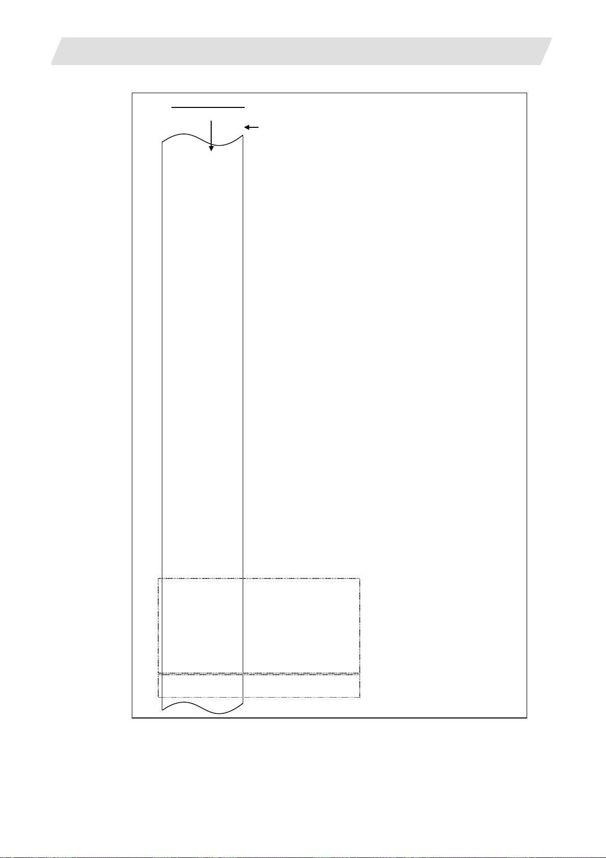
(4) Tape preparation for tape operation (with tape handler)
10cm
%
(EOR)
2m
If a tape handler is not used, there is no need for the 2-meter dummy at both ends of the tape
and for the head EOR (%) code.
• • • • • • • •
;;;;
Initial block
• • • • • • • • • • • • • • • •
(EOB)
Last block
(EOB)(EOB)
10cm %
(EOR)(EOB)
2m
8
Page 23
3. Data Formats
A
Y
( (
)
) (
)
)
)
)
@
)
)
A
ISO code (R-840)
Feed holes
8 7 6 5 4 3 2 1
Channel No.
3.1 Tape Codes
•
•
•
•
•
•
•
••
•
••
••
•
• •
•• •
•• •• •
• •• ••
•• •• •
• •• • •
• •• ••
•• •• •••
• •
•• •
•• •
• •
•• •• •
• •• • •
• •• ••
•• •• •••
•• ••
• ••
• ••• •
•
•
•
•
•
•
•
•• ••• ••
•• ••• • •
•
• •• • •
• •
•
•
•
••
••
••
Code A are stored on tape but an error results (except when they are used in the comment
section) during operation.
The B codes are non-working codes and are always ignored. Parity V check is not executed.
•
•
•
•
•
•
•• •
•• • •
•• ••
•• •••
•
••
•
••
•
•
•
•
•
•
•
•
• •
•
••
•
•••
•
•
•
•
•
•
•
•
•• ••
•• • •
•• ••
•• •
•• •••
•• • •
•• •
•
•
•
•
••• •
•
•• •
••• • •
•
•
•
•
•
••
•
•
•
•
•••
••• ••
••• •
••• ••
••• •••
•
•
••• •••
•
••• •••
•
•
1
•
2
•
3
••
4
5
6
7
8
9
•
0
•
B
•
C
••
D
E
F
G
H
I
•
J
K
L
M
N
O
P
Q
•
R
•
S
••
T
U
V
W
X
•
Z
+
.
,
/
%
LF(Line Feed) or NL
Control Out
Control In
•
:
#
••
*
=
[
]
SP(Space
CR(Carriage Return)
BS(Back Space
HT(Horizontal Tab
•
&
!
•
$
' (Apostrophe)
;
<
>
?
"
•
DEL(Delete
NULL
DEL(Delete
• Under the ISO code, IF or NL is EOB and % is EOR.
• Under the ISO code, CR is meaningless, and EOB will not occur.
Table of tape codes
B
9
Page 24
3. Data Formats
Alp
)
3.2 Program Formats
Function and purpose
The prescribed arrangement used when assigning control information to the controller is known as
the program format, and the format used with this controller is called the "word address format".
Detailed descripti on
(1) Word and address
A word is a collection of characters arranged in a specific sequence. This entity is used as the
unit for processing data and for causing the machine to execute specific operations. Each
word used for this controller consists of an alphabet letter and a number of several digits
(sometimes with a "-" sign placed at the head of the number.).
3.2 Program Formats
Word
*
Numerals
habet (address
Word configuration
The alphabet letter at the head of the word is the address. It defines the meaning of the
numerical information which follows it.
For details of the types of words and the number of significant digits of words used for this
controller, refer to the "format details".
(2) Blocks
A block is a collection of words. It includes the information which is required for the machine to
execute specific operations. One block unit constitutes a complete command. The end of each
block is marked with an EOB (end-of-block) code.
(Example 1)
G0X - 1000 ;
G1X - 2000F500 ;
(Example 2)
(G0X - 1000 ; )
G1X - 2000F500 ;
(3) Programs
A program is a collection of several blocks.
2 blocks
Since the semicolon in the parentheses will not result
in an EOB, it is 1 block.
10
Page 25

3. Data Formats
<Brief summary of format details>
Program No. L(O)8
Sequence No. N6
Preparatory function G3/G21
Movement
axis
Arc and
cutter
radius
Dwell
Feed
function
(Feed per
minute)
Feed
function
(Feed per
revolution)
Tool compensation
Miscellaneous function (M)
Spindle function (S)
Tool function (T)
2nd miscellaneous function A8/B8/C8
Subprogram
Fixed
cycle
0.001(°) mm/
0.001 inch
0.0001(°) mm/
0.0001 inch
0.00001(°) mm/
0.00001 inch
0.000001(°) mm/
0.000001 inch
0.001(°) mm/
0.001 inch
0.0001(°) mm/
0.0001 inch
0.00001(°) mm/
0.00001 inch
0.000001(°) mm/
0.000001 inch
0.001(rev)/(s)
0.001(°) mm/
0.001 inch
0.0001 (°) mm/
0.0001 inch
0.00001 (°) mm/
0.00001 inch
0.000001 (°) mm/
0.000001 inch
0.0001(°) mm/
0.0001 inch
0.00001 (°) mm/
0.00001 inch
0.000001 (°) mm/
0.000001 inch
0.0000001 (°) mm/
0.0000001 inch
0.001(°) mm/
0.001 inch
0.0001(°) mm/
0.0001 inch
0.00001(°) mm/
0.00001 inch
0.000001(°) mm/
0.000001 inch
Metric command Inch command
X+53 Y+53 Z+53 α+53 X+44 Y+44 Z+44 α+44 X+53 Y+53 Z+53 α+53 X+53 Y+53 Z+53 α+53
X+54 Y+54 Z+54 α+54 X+45 Y+45 Z+45 α+45 X+54 Y+54 Z+54 α+54 X+54 Y+54 Z+54 α+54
X+55 Y+55 Z+55 α+55 X+46 Y+46 Z+46 α+46 X+55 Y+55 Z+55 α+55 X+55 Y+55 Z+55 α+55
X+56 Y+56 Z+56 α+56 X+47 Y+47 Z+47 α+47 X+56 Y+56 Z+56 α+56 X+56 Y+56 Z+56 α+56
I+53 J+53 K+53 I+44 J+44 K+44 I+53 J+53 K+53
I+54 J+54 K+54 I+45 J+45 K+45 I+54 J+54 K+54
I+55 J+55 K+55 I+46 J+46 K+46 I+55 J+55 K+55
I+56 J+56 K+56 I+47 J+47 K+47 I+56 J+56 K+56
X53/P8
F63 F54 F63 F54 (Note 6)
F64 F55 F64 F55 (Note 6)
F65 F56 F65 F56 (Note 6)
F66 F57 F66 F57 (Note 6)
F33 F34 F33 F34 (Note 6)
F34 F35 F34 F35 (Note 6)
F35 F36 F35 F36 (Note 6)
F36 F37 F36 F37 (Note 6)
H3 D3
M8
S8
T8
P8 H5 L4
R+53 Q53 P8 L4 R+44 Q44 P8 L4 R+53 Q53 P8 L4 R+53 Q53 P8 L4
R+54 Q54 P8 L4 R+45 Q45 P8 L4 R+54 Q54 P8 L4 R+54 Q54 P8 L4
R+55 Q55 P8 L4 R+46 Q46 P8 L4 R+55 Q55 P8 L4 R+55 Q55 P8 L4
R+56 Q56 P8 L4 R+47 Q47 P8 L4 R+56 Q56 P8 L4 R+56 Q56 P8 L4
3.2 Program Formats
Rotary axis
(Metric command)
← ← ←
← ← ←
← ← ←
← ← ←
← ← ←
← ← ←
← ← ←
← ← ←
← ← ←
← ← ←
Rotary axis
(Inch command)
I+53 J+53 K+53
I+54 J+54 K+54
I+55 J+55 K+55
I+56 J+56 K+56
(Note 5)
(Note 5)
(Note 5)
(Note 5)
(Note 1) α indicates the additional axis address, such as A, B or C.
(Note 2) The number of digits check for a word is carried out with the maximum number of digits of that address.
(Note 3) Numerals can be used without the leading zeros.
11
Page 26

3. Data Formats
3.2 Program Formats
(Note 4) The description of the brief summary is explained below:
Example 1 : L(O)8 :8-digit program No.
Example 2 : G21 :Dimension G is 2 digits to the left of the decimal point, and 1 digit to the right.
Example 3 : X+53 :Dimension X uses + or - sign and represents 5 digits to the left of the decimal
point and 3 digits to the right.
For example, the case for when the X axis is positioned (G00) to the 45.123 mm
position in the absolute value (G90) mode is as follows:
G00 X45.123 ;
3 digits below the decimal point
5 digits above the decimal point, so it's +00045, but the
leading zeros and the mark (+) have been omitted.
G0 is possible, too.
(Note 5) If an arc is commanded using a rotary axis and linear axis while inch commands are being used, the
degrees will be converted into 0.1 inches for interpolation.
(Note 6) While inch commands are being used, the rotary axis speed will be in increments of 10 degrees.
Example: With the F1. (per-minute-feed) command, this will become the 10 degrees/minute command.
(Note 7) The decimal places below the decimal point are ignored when a command, such as an S command,
with an invalid decimal point has been assigned with a decimal point.
(Note 8) This format is the same for the value input from the memory, MDI or setting and display unit.
(Note 9) Command the program No. in an independent block. Command the program No. in the head block of
the program.
(Note 10) The addresses of the program No. and subprogram call No. differ according to the parameter.
The system must be formatted when this parameter is changed.
Setting of
“#11009 M2 labelO”
0 L L
1 O A
This manual describes on the assumption that the parameter is set to "0".
Address of the
program No.
Address to call the
subprogram
12
Page 27

3. Data Formats
3.3 Tape Memory Format
Function and purpose
(1) Storage tape and significant sections
The others are about from the current tape position to the EOB. Accordingly, under normal
conditions, operate the tape memory after resetting.
The significant codes listed in "Table of tape codes" in "3.1 Tape Codes" in the above
significant section are actually stored into the memory. All other codes are ignored and are not
stored.
The data between control out "(" and control in ")" are stored into the memory.
3.4 Optional Block Skip
3.4.1 Optional Block Skip ; /
Function and purpose
This function selectively ignores specific blocks in a machining program which starts with the "/"
(slash) code.
Detailed description
3.3 Tape Memory Format
(1) Provided that the optional block skip switch is ON, blocks starting with the "/" code are ignored.
They are executed if the switch is OFF.
Parity check is valid regardless of whether the optional block skip switch is ON or OFF.
When, for instance, all blocks are to be executed for one workpiece but specific block are not
to be executed for another workpiece, the same command tape can be used to machine
different parts by inserting the "/" code at the head of those specific blocks.
Precautions for using optional block skip
(1) Put the "/" code for optional block skip at the beginning of a block. If it is placed inside the block,
it is assumed as a user macro, a division instruction.
Example : N20 G1 X25./Y25. ;.... NG (User macro, a division instruction; a program error
results.)
/N20 G1 X25. Y25. ;.....OK
(2) Parity checks (H and V) are conducted regardless of the optional block skip switch position.
(3) The optional block skip is processed immediately before the pre-read buffer.
Consequently, it is not possible to skip up to the block which has been read into the pre-read
buffer.
(4) This function is valid even during a sequence number search.
(5) All blocks with the "/" code are also input and output during tape storing and tape output,
regardless of the position of the optional block skip switch.
13
Page 28

3. Data Formats
3.4.2 Optional Block Skip Addition ; /n
Function and purpose
Whether the block with "/n (n:1 to 9)" (slash) is executed during automatic operation and searching
is selected.
By using the machining program with "/n" code, different parts can be machined by the same
program.
Detailed description
The block with "/n" (slash) code is skipped when the "/n" is programmed to the head of the block
and the optional block skip signal is turned ON.
For the block with the "/n" code inside the block (not the head of block), the program is operated
according to the value of the parameter "#1226 aux10/bit1" setting.
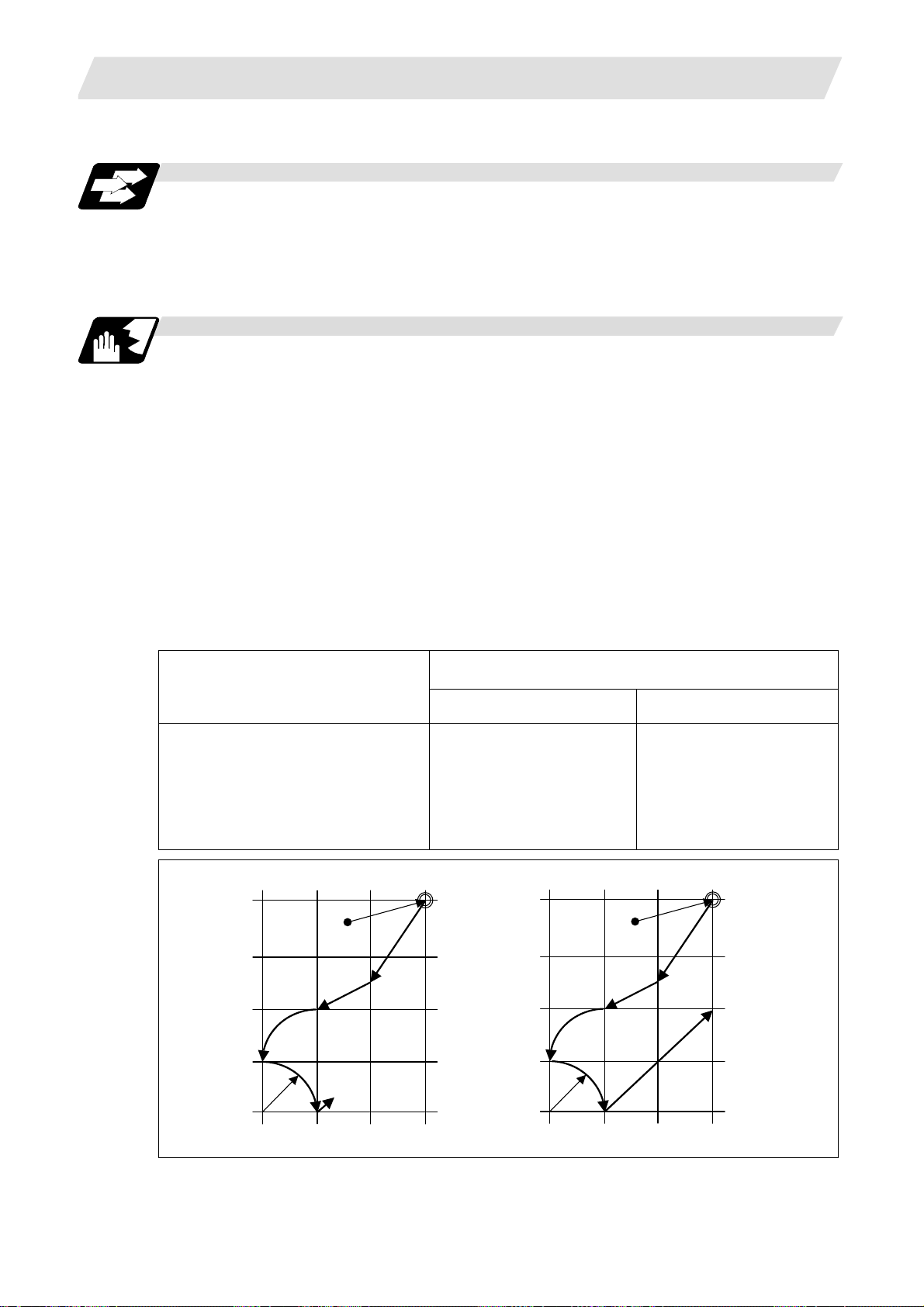
When the optional block skip signal is OFF, the block with "/n" is executed.
Example of program
(1) When the 2 parts like the figure below are machined, the following program is used. When the
optional block skip 5 signal is ON, the part 1 is created. When the optional block skip 5 signal is
OFF, the part 2 is created.
<Program>
N1 G54;
N2 G90G81X50. Z-20. R3. F100;
/5 N3 X30.;
N4 X10.;
N5 G80;
M02;
Part 1
the optional block skip 5 signal ON
3.4 Optional Block Skip
Part 2
the optional block skip 5 signal OFF
N4 N2 N2 N3
14
N4
Page 29

3. Data Formats
(2) When two or more "/n" codes are commanded to the head of the same block, the block is
ignored if either of the optional block skip signal corresponding to the command is ON.
<Program>
N01 G90 Z3. M03 S1000;
/1/2 N02 G00 X50.;
/1/2 N03 G01 Z-20. F100;
/1/2 N04 G00 Z3.;
/1 /3 N05 G00 X30.;
/1 /3 N06 G01 Z-20. F100;
/1 /3 N07 G00 Z3.;
/2/3 N08 G00 X10.;
/2/3 N09 G01 Z-20. F100;
/2/3 N10 G00 Z3.;
N11 G28 X0 M05;
N12 M02;
(3) When the parameter "#1226 aux10/bit1" is "1", when two or more "/n" are commanded inside
the same block, the commands following "/n" in the block are ignored if either of the optional
block skip signal corresponding to the command is ON.
N01 G91 G28 X0.Y0.Z0.;
N02 G01 F1000;
N03 X1. /1 Y1. /2 Z1.;
N04 M30;
3.4 Optional Block Skip
(a) Optional block skip 1 signal ON
(Optional block skip 2, 3 signals OFF)
N01 -> N08 -> N09 -> N10 -> N11 -> N12
(b) Optional block skip 2 signal ON
(Optional block skip 1, 3 signals OFF)
N01 -> N05 -> N06 -> N07 -> N11 -> N12
(c) Optional block skip 3 signal ON
(Optional block skip 1, 2 signals OFF)
N01 -> N02 -> N03 -> N04 -> N11 -> N12
(a) When the optional block skip 1 signal is
ON and the optional block skip 2 signal is
OFF, "Y1. Z1." is ignored
(b) When the optional block skip 1 signal is
OFF and the optional block skip 2 signal is
ON, "Z1." is ignored.
15
Page 30
3. Data Formats
3.5 Program/Sequence/Block Numbers ; L(O), N
3.5 Program/Sequence/Block Numbers ; L(O), N
Function and purpose
These numbers are used for monitoring the execution of the machining programs and for calling
both machining programs and specific stages in machining programs.
(1) Program numbers are classified by workpiece correspondence or by subprogram units, and
they are designated by the address "L" (or "0") followed by a number with up to 8 digits.
(2) Sequence numbers are attached where appropriate to command blocks which configure
machining programs, and they are designated by the address "N" followed by a number with
up to 6 digits.
(3) Block numbers are automatically provided internally. They are preset to zero every time a
program number or sequence number is read, and they are counted up one at a time unless
program numbers or sequence numbers are commanded in blocks which are subsequently
read.
Consequently, all the blocks of the machining programs given in the table below can be
determined without further consideration by combinations of program numbers, sequence
numbers and block numbers.
Machining program
L12345678 (DEMO, PROG) ; 12345678 0 0
G92 X0 Y0 ; 12345678 0 1
G90 G51 X-150. P0.75 ; 12345678 0 2
N100 G00 X-50. Y-25. ; 12345678 100 0
N110 G01 X250. F300 ; 12345678 110 0
Y-225. ; 12345678 110 1
X-50. ; 12345678 110 2
Y-25.; 12345678 110 3
N120 G51 Y-125. P0.5 ; 12345678 120 0
N130 G00 X-100. Y-75. ; 12345678 130 0
N140 G01 X-200. ; 12345678 140 0
Y-175. ; 12345678 140 1
X-100. ; 12345678 140 2
Y-75. ; 12345678 140 3
N150 G00 G50 X0 Y0 ; 12345678 150 0
N160 M02 ; 12345678 160 0
%
Program No. Sequence No. Block No.
Monitor display
16
Page 31
3. Data Formats
•
•
• • •
• • • • • • • • • • • • •
•
•
• •
•
•
• • •
• • •
• •
•
• • •
•
• •
•
• • • • • • • • •
•
• •
• • •
3.6 Parity H/V
Function and purpose
Parity check provides a mean of checking whether the tape has been correctly perforated or not.
This involves checking for perforated code errors or, in other words, for perforation errors. There
are two types of parity check: Parity H and Parity V.
(1) Parity H
3.6 Parity H/V
Parity H checks the number of holes configuring a character and it is done during tape
operation, tape input and sequence number search.
A parity H error is caused in the following cases.
(a) ISO code
When a code with an odd number of holes in a significant data section has been detected.
(b) EIA code
When a code with an even number of holes in a significant data section has been
detected.
Parity H error example
• • • •
•
• • • • • • • • • • • • • • • • • • • • • • • • • • • • • • • • • • • • • • • • • • • • • • • • •
• • • • • • • • • • • • • • •
•
•
• • • • • • • • •
• • •
(2) Parity V
• • • • •
• • • • • • • • • • • • • • • • •
• • • • • • • • • • • • • •
When a parity H error occurs, the tape stops following the alarm code.
A parity V check is done during tape operation, tape input and sequence number search when
the I/O PARA #9n15 (n is the unit No.1 to 5) parity V check function is set to "1". It is not done
during memory operation.
A parity V error occurs in the following case: when the number of codes from the first
significant code to the EOB (;) in the significant data section in the vertical direction of the tape
is an odd number, that is, when the number of characters in one block is odd.
When a parity V error is detected, the tape stops at the code following the EOB (;).
(Note 1) Among the tape codes, there are codes which are counted as characters for parity
(Note 2) Any space codes which may appear within the section from the initial EOB code to
• •
• • • • • • • • • •
•
•
• • • •
• • •
• • • • • • •
This character causes a parity H error.
and codes which are not counted as such. For details, refer to the "Table of tape
codes" in "3.1 Tape Codes".
the address code or "/" code are counted for parity V check.
17
Page 32

3. Data Formats
3.7 G Code Lists
Function and purpose
G code Group Function
Δ 00 01 Positioning 6.1
Δ 01 01 Linear interpolation 6.2
02 01
03 01
02.1 01 Spiral/Conical interpolation CW (type1) 6.13
03.1 01 Spiral/Conical interpolation CCW (type1) 6.13
02.3 01 Exponential function interpolation positive rotation 6.11
03.3 01 Exponential function interpolation negative rotation 6.11
02.4 01 3-dimensional circular interpolation 6.14
03.4 01 3-dimensional circular interpolation 6.14
04 00 Dwell 8.1
05 00
05.1 00
06.2 01 NURBS interpolation 6.15
07 00
07.1
107
08 00 High-accuracy control 13.15
09 00 Exact stop check 7.9
10 00
11.1 00 Program data input cancel
11 00 Program compensation data input to variable 12.8
12 00 Circular cut CW (clockwise) 13.10
13 00 Circular cut CCW (counterclockwise) 13.10
12.1 21 Polar coordinate interpolation ON 6.10
* 13.1 21 Polar coordinate interpolation cancel 6.10
14 00 Coordinate data read 13.27
* 15 18 Polar coordinate command OFF 6.12
16 18 Polar coordinate command ON 6.12
Δ 17 02 Plane selection X-Y 6.3
Δ 18 02 Plane selection Z-X 6.3
Δ 19 02 Plane selection Y-Z 6.3
Δ 20 06 Inch command 5.2
Δ 21 06 Metric command 5.2
3.7 G Code Lists
Section
Circular interpolation CW (clockwise)
R-specified circular interpolation CW
Helical interpolation CW
Spiral/Conical interpolation CW (type2)
Circular interpolation CCW (counterclockwise)
R-specified circular interpolation CCW
Helical interpolation CCW
Spiral/Conical interpolation CCW (type2)
High-speed machining mode
High-speed high-accuracy control II
High-speed high-accuracy control I
Spline
Hypothetical axis interpolation
21 Cylindrical interpolation 6.9
Program data input (parameter /compensation data/parameter
coordinate rotation data)
6.4
6.5
6.6
6.13
6.4
6.5
6.6
6.13
13.16
13.17
13.17
13.18
6.16
12.7
13.11
13.22
12.7
13.11
18
Page 33

3. Data Formats
3.7 G Code Lists
G code Group Function
22 00 Subprogram call / figure rotation ON 13.3
23 00 Subprogram return / figure rotation cancel 13.3
22.1 04 Stroke check before travel ON 15.7
23.1 04 Stroke check before travel cancel 15.7
24
25
26
27 00 Reference position check 14.9
28 00 Reference position return 14.7
29 00 Start position return 14.7
30 00 2nd to 4th reference position return 14.8
30.1 00 Tool change position return 1 13.13
30.2 00 Tool change position return 2 13.13
30.3 00 Tool change position return 3
30.4 00 Tool change position return 4 13.13
30.5 00 Tool change position return 5 13.13
30.6 00 Tool change position return 6 13.13
31 00 Skip
Multi-step skip function 2
31.1 00 Multi-step skip function 1-1 15.3
31.2 00 Multi-step skip function 1-2 15.3
31.3 00 Multi-step skip function 1-3 15.3
32
33 01 Thread cutting 6.7
34 00 Special fixed cycle (bolt hole circle) 13.2
35 00 Special fixed cycle (line at angle) 13.2
36 00 Special fixed cycle (arc) 13.2
37 00 Special fixed cycle (grid) 13.2
37.1 00 Automatic tool length measurement 15.1
38 00 Tool radius compensation vector designation 12.4
39 00 Tool radius compensation corner arc 12.4
* 40 07
41 07
42 07
* 40.1 15 Normal line control cancel 13.14
41.1 15 Normal line control left ON 13.14
42.1 15 Normal line control right ON 13.14
43 08 Tool length compensation 12.2
* 44 08
43.1 08 Tool length compensation along the tool axis 12.3
43.4 08 Tool center point control type 1 13.24
43.5 08 Tool center point control type 2 13.24
45 00 Tool position offset (extension) 12.6
46 00 Tool position offset (reduction) 12.6
47 00 Tool position offset (doubled) 12.6
48 00 Tool position offset (halved) 12.6
49
Tool radius compensation cancel
3-dimentional tool radius compensation cancel
Tool radius compensation left
3-dimentional tool radius compensation left
Tool radius compensation right
3-dimentional tool radius compensation right
Tool length compensation cancel
Tool center point control cancel
Section
13.13
15.2
15.4
12.4
12.5
12.4
12.5
12.4
12.5
12.2
13.24
19
Page 34

3. Data Formats
3.7 G Code Lists
G code Group Function
* 50 11 Scaling cancel 13.20
51 11 Scaling ON 13.20
* 50.1 19 G command mirror image cancel 13.6
51.1 19 G command mirror image ON 13.6
52 00 Local coordinate system setting 14.11
53 00 Basic machine coordinate system selection 14.4
* 54 12 Workpiece coordinate system 1 selection 14.10
55 12 Workpiece coordinate system 2 selection 14.10
56 12 Workpiece coordinate system 3 selection 14.10
57 12 Workpiece coordinate system 4 selection
58 12 Workpiece coordinate system 5 selection
59 12 Workpiece coordinate system 6 selection
54.1 12 Workpiece coordinate system selection 48 / 96 sets extended
60 00 Unidirectional positioning
61 13 Exact stop check mode
61.1 13 High-accuracy control 1 ON
61.2 13 High-accuracy spline interpolation 13.19
62 19 G command mirror image
63 13 Tapping mode
63.1 13 Synchronous tapping mode (normal tapping)
63.2 13 Synchronous tapping mode (reverse tapping)
* 64 13 Cutting mode 7.14
65 00 User macro call 13.5.1
66 14 User macro modal call A 13.5.1
66.1 14 User macro modal call B 13.5.1
* 67 14 User macro modal call cancel 13.5.1
68 00 Subprogram return 13.5.1
69 00 End point error check cancellation 13.26
68.1 16
* 69.1 16
70 09 User fixed cycle
71 09 User fixed cycle
72 09 User fixed cycle
73 09 Fixed cycle (step) 13.1.1
74 09 Fixed cycle (reverse tap) 13.1.1
75 09 Fixed cycle (circle cutting cycle) 13.1.1
76 09 Fixed cycle (fine boring) 13.1.1
77 09 User fixed cycle
78 09 User fixed cycle
79 09 User fixed cycle
* 80 09 Fixed cycle cancel 13.1.1
81 09 Fixed cycle (drill/spot drill) 13.1.1
82 09 Fixed cycle (drill/counter boring) 13.1.1
83 09 Fixed cycle (deep drilling) 13.1.1
84 09 Fixed cycle (tapping) 13.1.1
85 09 Fixed cycle (boring) 13.1.1
86 09 Fixed cycle (boring) 13.1.1
87 09 Fixed cycle (back boring) 13.1.1
88 09 Fixed cycle (boring) 13.1.1
89 09 Fixed cycle (boring) 13.1.1
Programmable coordinate rotation mode ON/3-dimensional
coordinate conversion mode ON
Programmable coordinate rotation mode OFF/3-dimensional
coordinate conversion mode OFF
Section
14.10
14.10
14.10
14.10
6.8
7.10
13.15
13.6
7.13
13.21
13.23
13.21
13.23
20
Page 35

3. Data Formats
g
3.8 Precautions Before Starting Machining
G code Group Function
Δ 90 03 Absolute value command 5.1
Δ 91 03 Incremental command value 5.1
92 00 Coordinate system setting / Spindle clamp speed setting 14.5
92.1 00 Workpiece coordinate system pre-setting 14.12
93 05 Inverse time feed 7.5
Δ 94 05 Per-minute feed (asynchronous feed) 7.4
Δ 95 05 Per-revolution feed (synchronous feed) 7.4
Δ 96 17 Constant surface speed control ON 10.3
Δ 97 17 Constant surface speed control OFF 10.3
* 98 10 Fixed cycle Initial level return 13.1.2
99 10 Fixed cycle R point level return 13.1.2
100 to
255
(Note 1) Codes marked with * are codes that must be or are selected in the initial state.
The codes marked with Δ are codes that should be or are selected in the initial state by
(Note 2) If two or more G codes from the same code are commanded, the latter G code will be
(Note 3) This G code list is a list of conventional G codes. Depending on the machine, movements
(Note 4) Whether the modal is initialized or not depends on each reset input.
00 User macro (G code call) Max. 10 13.5.2
the parameters.
valid.
that differ from the conventional G commands may be included when called by the G
code macro. Refer to the Instruction Manual issued by the tool builder.
(1) "Reset 1"
The modal is initialized when the reset initial parameter "#1151 rstinit" turns ON.
(2) "Reset 2" and "Reset & rewind"
The modal is initialized when the signal is input.
(3) Resetting when emergency stop is canceled
Follows "Reset 1".
(4) When modal is automatically reset at the start of individual functions such as
reference position return.
Follows "Reset & rewind".
Section
CAUTION
The commands with "no value after G" will be handled as "G00".
3.8 Precautions Before Starting Machining
Precautions before starting machinin
CAUTION
When creating the machining program, select the appropriate machining conditions so that the
machine, NC performance, capacity and limits are not exceeded. The examples do not allow
for the machining conditions.
Before starting actual machining, always carry out dry operation to confirm the machining
program, tool compensation amount and workpiece offset amount, etc.
21
Page 36

4. Buffer Register
r
y
Analysi
A
4. Buffer Register
4.1 Input Buffer
Tape
Function and purpose
When the pre-read buffer is empty during a tape operation or RS232C operation, the contents of
the input buffer are immediately transferred to the pre-read buffers and, provided that the data
stored in the input buffer do not exceed 250 x 4 characters, the following data (Max. 250
characters) are read and loaded into the input buffer.
This buffer is designed to eliminate the operational delay originating in the readout time of the tape
reader and to smooth out the block joints.
The pre-reading effects are lost, however, when the block execution time is shorter than the tape
readout time of the following block.
(Buffer size : 250 x 5 characters)
Input buffe
4.1 Input Buffer
s processing
Max. 5 execution blocks
Pre-read
buffer 5
Keyboard
Buffer 4
Memor
MDI data
Mode
switching
Note : Data equivalent to 1 block are stored in 1 pre-read buffer.
Buffer 3
Buffer 2
Buffer 1
rithmetic
processing
The input buffer has a memory capacity of 250 x 5 characters (including the EOB code).
(1) The contents of the input buffer register are updated in 250-character units.
(2) Only the significant codes in the significant data section are read into the input buffer.
(3) When codes (including "(" and ")") are sandwiched in the control in or control out mode and the
optional block skip function is ON, the data extending from the "/" (slash) code up to the EOB
code are read into the input buffer.
(4) The input buffer contents are cleared with resetting.
(Note 1) The input buffer size (250 characters) differs according to the model.
22
Page 37

4. Buffer Register
4.2 Pre-read Buffers
Function and purpose
During automatic processing, the contents of 1 block are normally pre-read so that program
analysis processing is conducted smoothly. However, during tool radius compensation, a
maximum of 5 blocks are pre-read for the intersection point calculation including interference
check.
The specifications of the data in 1 block are as follows:
(1) The data of 1 block are stored in this buffer.
(2) Only the significant codes in the significant data section are read into the pre-read buffer.
(3) When codes are sandwiched in the control in and control out, and the optional block skip
function is ON, the data extending from the "/" (slash) code up to the EOB code are not read
into the pre-read buffer.
(4) The pre-read buffer contents are cleared with resetting.
(5) When the single block function is ON during continuous operation, the pre-read buffer stores
the following block data and then stops operation.
Other precautions
4.2 Pre-read Buffers
(1) Depending on whether the program is executed continuously or by single blocks, the timing of
the valid/invalid for the external control signals for the block skip and others will differ.
(2) If the external control signal such as optional block skip is turned ON/OFF with the M
command, the external control operation will not be effective on the program pre-read with the
buffer register.
(3) According to the M command that operates the external controls, it prohibits pre-reading, and
the recalculation is as follows:
The M command that commands the external controls is distinguished at the PLC, and the
"recalculation request" for PLC -> NC interface table is turned ON.
(When the "recalculation request" is ON, the program that has been pre-read is reprocessed.)
23
Page 38

5. Position Commands
5. Position Commands
5.1 Position Command Methods ; G90, G91
Function and purpose
By using the G90 and G91 commands, it is possible to execute the next coordinate commands
using absolute values or incremental values.
The R-designated circle radius and the center of the circle determined by I, J, K are always
incremental value commands.
Command format
G9D X__ Y__ Z__ α__;
G90 :Absolute command
G91 :Incremental command
α :Additional axis
Detailed description
(1) Regardless of the current position, in the absolute
value mode, it is possible to move to the position of the
workpiece coordinate system that was designated in
the program.
N 1 G90 G00 X0 Y0 ;
5.1 Position Command Methods ; G90, G91
Y
200.
Tool
100.
N1
In the incremental value mode, the current position is
the start point (0), and the movement is made only the
value determined by the program, and is expressed as
an incremental value.
W
100.
N2
200.
X
300.
N 2 G90 G01 X200. Y50. F100;
N 2 G91 G01 X200. Y50. F100;
Using the command from the 0 point in the workpiece coordinate system, it becomes the same
coordinate command value in either the absolute value mode or the incremental value mode.
(2) For the next block, the last G90/G91 command that
was given becomes the modal.
(G90)
N 3 X100. Y100.;
The axis moves to the workpiece
coordinate system X = 100mm and
Y
200.
100.
N3
Y = 100mm position.
(G91)
W
100.
200.
N 3 X-100. Y50.;
300.
X
The X axis moves to -100.mm and the Y axis to +50.0mm as an incremental
value, and as a result X moves to 100.mm and Y to 100.mm.
24
Page 39

5. Position Commands
(3) Since multiple commands can be issued in the same block, it is possible to command specific
addresses as either absolute values or incremental
values.
N 4 G90 X300. G91 Y100.;
The X axis is treated in the absolute value
mode, and with G90 is moved to the workpiece
coordinate system 300.mm position. The Y
axis is moved +100.mm with G91. As a result,
Y moves to the 200.mm position. In terms of
the next block, G91 remains as the modal and
becomes the incremental value mode.
(4) When the power is turned ON, it is possible to select whether you want absolute value
commands or incremental value commands with the #1073 I_Absm parameter.
(5) Even when commanding with the manual data input (MDI), it will be treated as a modal from
that block.
5.1 Position Command Methods ; G90, G91
Y
200.
100.
N4
W
200. 100.
300.
X
25
Page 40

5. Position Commands
5.2 Inch/Metric Command Change; G20, G21
5.2 Inch/Metric Command Change; G20, G21
Function and purpose
These G commands are used to change between the inch and millimeter (metric) systems.
Command format
G20/G21;
G20 : Inch command
G21 : Metric command
Detailed description
The G20 and G21 commands merely select the command units. They do not select the Input units.
G20 and G21 selection is meaningful only for linear axes and it is meaningless for rotation axes.
Output unit, command unit and setting unit
The counter or parameter setting and display unit is determined by parameter "#1041 I_inch".
For the movement/speed command, the followings will be resulted:
The movement/speed command will be displayed as metric units when "#1041 I_inch" is ON during
the G21 command mode.
The internal unit metric data of the movement/speed command will be converted into an inch unit
and displayed when "#1041 I_inch" is OFF during the G20 command mode.
The command unit for when the power is turned ON and reset is decided by combining the
parameters "#1041 I_inch", "#1151 rstint" and "#1210 RstGmd/bit5".
NC axis
Item
Movement/
speed command
Counter display Metric Metric Inch Inch
Speed display Metric Metric Inch Inch
User parameter
setting/display
Workpiece/
tool offset
setting/display
Handle feed
command
PLC axis
Item
Movement/
speed command
Counter display Metric Inch
User parameter
setting/display
Initial inch OFF
(metric internal unit)
#1041 I_inch=0
G21 G20 G21 G20
Metric Inch Metric Inch
Metric Metric Inch Inch
Metric Metric Inch Inch
Metric Metric Inch Inch
#1042 pcinch=0
(metric)
Metric Inch
Metric Inch
Initial inch ON
(inch internal unit)
#1041 I_inch=1
#1042 pcinch=1
(inch)
26
Page 41

5. Position Commands
Precautions
(1) The parameter and tool data will be input/output with the "#1041 I_inch" setting unit.
If "#1041 I_inch" is not found in the parameter input data, the unit will follow the unit currently
set to NC.
(2) The unit of read/write used in PLC window is fixed to metric unit regardless of a parameter and
G20/G21 command modal.
(3) A program error (P33) will occur if G20/G21 command is issued in the same block as following
G code. Command in a separate block.
G05 (High-speed machining mode)
G7.1 (Cylindrical Interpolation)
G12.1 (Polar coordinate interpolation)
5.2 Inch/Metric Command Change; G20, G21
27
Page 42
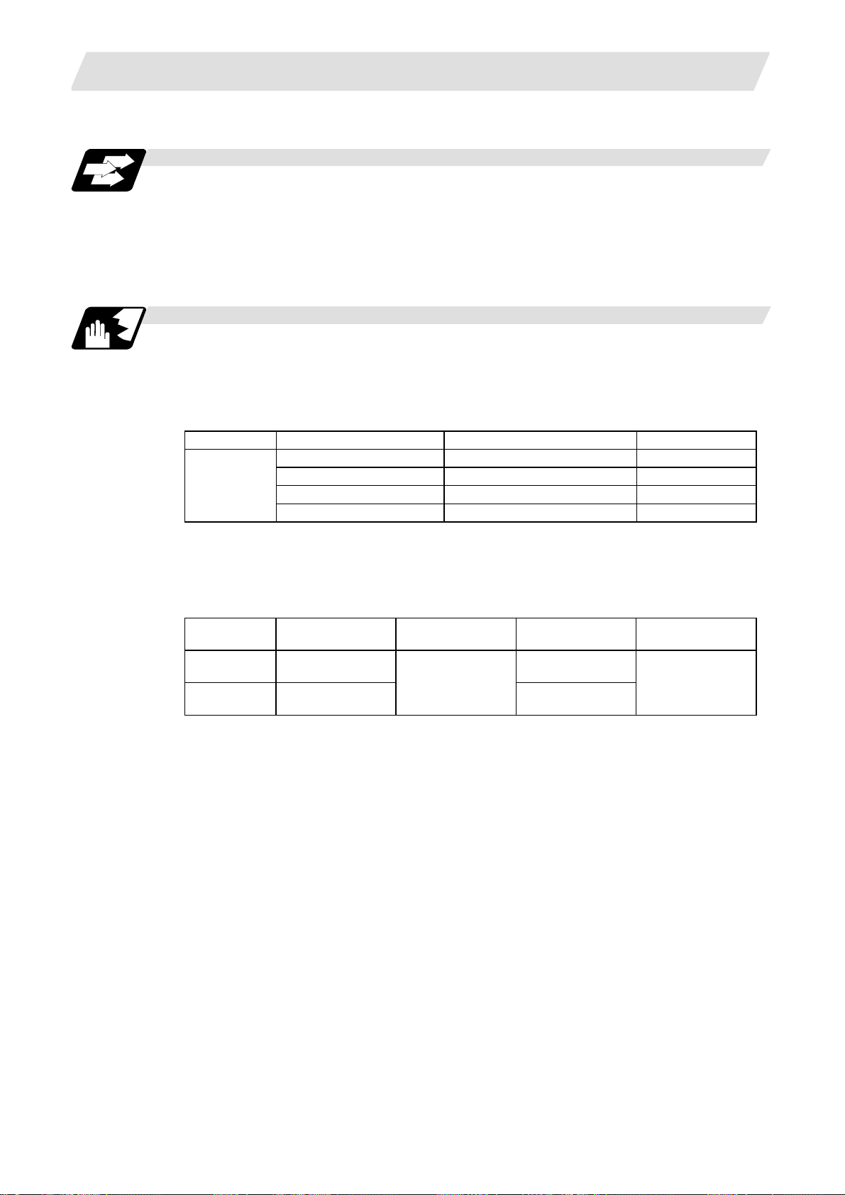
5. Position Commands
5.3 Decimal Point Input
Function and purpose
This function enables the decimal point command to be input. It assigns the decimal point in
millimeter or inch units for the machining program input information that defines the tool paths,
distances and speeds. The parameter "#1078 Decpt2" selects whether type I (minimum input
command unit) or type II (zero point) is to apply for the least significant digit of data without a
decimal point.
Detailed description
(1) The decimal point command is valid for the distances, angles, times, speeds and scaling rate,
in machining programs. (Note, only after G51)
(2) In decimal point input type 1 and type 2, the values of the data commands without the decimal
points are shown in the table below.
Command Command unit Type 1 Type 2
X1 ;
(3) The valid addresses for the decimal points are X, Y, Z, U, V, W, A, B, C, I, J, K, E, F, P, Q, and
R. However, P is valid only during scaling. For details, refer to the list.
(4) In decimal point command, the valid range of command value is as shown below. (Input
command unit cunit = 10)
Input unit
[mm]
Input unit
[inch]
(5) The decimal point command is valid even for commands defining the variable data used in
subprograms.
(6) While the smallest decimal point command is validated, the smallest unit for a command
without a decimal point designation is the smallest command input unit set in the specifications
(1µm, 10µm, etc.) or mm can be selected. This selection can be made with parameter "#1078
Decpt2".
(7) Decimal point commands for decimal point invalid addresses are processed as integer data
only and everything below the decimal point is ignored. Addresses which are invalid for the
decimal point are D, H, L, M, N, O, S and T. All variable commands, however, are treated as
data with decimal points.
(8) "Input command increment tenfold" is applied in the decimal point type I mode, but not in the
decimal point type II mode.
5.3 Decimal Point Input
cunit = 10000 1000 (µm, 10-4 inch, 10-3 °) 1 (mm, inch, °)
cunit = 1000 100 1
cunit = 100 10 1
cunit = 10 1 1
Movement
command (linear)
-99999.999 to
99999.999
-9999.9999 to
9999.9999
Movement
command (rotary)
-99999.999 to
99999.999
Feedrate Dwell
0. 001 to
10000000.000
0. 0001 to
1000000.0000
0 to 99999.999
28
Page 43
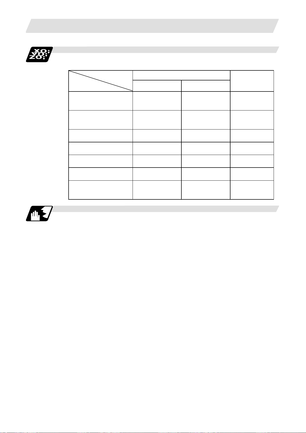
5. Position Commands
Example of program
(1) Example of program for decimal point valid address
Program example
G0X123.45
(decimal points are all mm
points)
G0X12345
#111 = 123, #112 = 5.55
X#111 Y#112
#113 = #111+#112
(addition)
#114 = #111-#112
(subtraction)
#115 = #111∗#112
(multiplication)
#116 = #111/#112
#117 = #112/#111
(division)
Decimal point input I/II and decimal point command valid/invalid
If a command does not use a decimal point at an address where a decimal point command is valid
in the table on the following page, it is handled differently between decimal point input I and II
modes as explained below.
A command using a decimal point is handled the same way in either the decimal point input I or II
mode.
(1) Decimal point input I
The least significant digit place of command data corresponds to the command unit.
(Example) Command "X1" in the 1μm system is equivalent to command "X0.001".
(2) Decimal point input II
The least significant digit place of command data corresponds to the decimal point.
(Example) Command "X1" in the 1μm system is equivalent to command "X1.".
(Note) When a four rules operator is contained, the data will be handled as that with a decimal
Specification
point.
division
5.3 Decimal Point Input
Decimal point command 1
When 1 = 1μm When 1 = 10μm
X123.450mm X123.450mm X123.450mm
X12.345mm
(last digit is 1μm
unit)
X123.000mm,
Y5.550mm
#113 = 128.550 #113 = 128.550 #113 = 128.550
#114 = 117.450 #114 = 117.450 #114 = 117.450
#115 = 682.650 #115 = 682.650 #115 = 682.650
#116 = 22.162
#117 = 0.045
X123.450mm X12345.000mm
X123.000mm,
Y5.550mm
#116 = 22.162
#117 = 0.045
Decimal point
command 2
1 = 1mm
X123.000mm,
Y5.550mm
#116 = 22.162
#117 = 0.045
(Example) When the min. input command unit is 1μm :
G0 x 123 + 0 ; ... X axis 123mm command. It will not be 123μm.
29
Page 44

5. Position Commands
5.3 Decimal Point Input
Addresses used and validity/invalidity of decimal point commands are shown below.
Address
Decimal point
command
Application
A Valid Coordinate position data
Invalid Revolving table
Invalid Miscellaneous function code
Valid Angle data
Invalid Data settings, axis numbers (G10)
Invalid Subprogram call : program No. (label O)
B Valid Coordinate position data
Invalid Revolving table
Invalid Miscellaneous function code
C Valid Coordinate position data
Invalid Revolving table
Invalid Miscellaneous function code
Valid Corner chamfering amount ,c
D Invalid Compensation numbers (tool position, tool radius)
Valid Automatic tool length measurement: deceleration
distance d
Invalid Data setting: byte type data
Invalid Subprogram storing device number ,D
E Valid Inch thread: number of ridges,
precision thread: lead
Valid Dwell time at hole bottom of fixed cycle (label L, O)
F Valid Feedrate, automatic tool length measurement speed
Valid Thread lead
Valid Number of Z axis pitch in synchronous tap
G Valid Preparatory function code
H Invalid Tool length compensation number
Invalid Sequence number in subprogram (label L, O)
Invalid Subprogram return destination sequence No. (label L, O)
Invalid Program parameter input: bit type data
Invalid Basic spindle selection
I Valid Arc center coordinates
Invalid Center of figure rotation (incremental)
Valid Tool radius compensation vector components
Valid Hole pitch in the special fixed cycle
Valid Circle radius of cut circle (increase amount)
Valid G0/G1 imposition width, drilling cycle G0 imposition width ,I
Valid Stroke check before travel: lower limit coordinates
Remarks
30
Page 45

5. Position Commands
5.3 Decimal Point Input
Address
Decimal point
command
Application
J Valid Arc center coordinates
Invalid Center of figure rotation (incremental)
Valid Tool radius compensation vector components
Valid Special fixed cycle's hole pitch or angle
Valid G0/G1 imposition width, drilling cycle G1 imposition width
Valid Stroke check before travel: lower limit coordinates
K Valid Arc center coordinates
Invalid Center of figure rotation (incremental)
Valid Tool radius compensation vector components
Invalid Number of holes of the special fixed cycle
Invalid Number of drilling cycle repetitions
Valid Stroke check before travel: lower limit coordinates
L Invalid Subprogram call program No. (label L)
Invalid Program tool compensation input/workpiece offset input:
type selection
Invalid Program parameter input: data setting selection L70
Invalid Program parameter input: 2-word type data 4 bytes
Invalid Tool life data
M Invalid Miscellaneous function codes
N Invalid Sequence numbers
Invalid Program parameter input: data numbers
O Invalid Program numbers (label O)
P Invalid/Valid Dwell time Parameter
Invalid Subprogram call : number of repetition (label L, O)
Invalid/Valid Dwell at tap cycle hole base Parameter
Invalid Number of holes of the special fixed cycle (label L)
Invalid Amount of helical pitch
Invalid Offset number (G10)
Invalid Constant surface speed control axis number
Invalid Program parameter input: broad classification number
Invalid Multi-step skip function 2 signal command
Invalid 2nd, 3rd, 4th reference position return number
Valid Scaling magnification
Invalid High-speed mode type
Invalid Type of the coordinate to be read
Invalid Transmission source compensation No. of program
compensation data input to variable
Invalid Extended workpiece coordinate system No.
Invalid Tool life data group No.
Remarks
L2, L20,
L12, L10, L13,
L11
31
Page 46

5. Position Commands
5.3 Decimal Point Input
Address
Decimal point
command
Application
Q Valid Cut amount of deep hole drill cycle
Valid Shift amount of back boring
Valid Shift amount of fine boring
Invalid Minimum spindle clamp speed
Valid Starting shift angle for screw cutting
Invalid Transmission destination variable No. of program
compensation data input to variable
Invalid Tool life data management method
R Valid R-point in the fixed cycle
Valid R-specified arc radius
Valid Corner R arc radius ,R
Valid Offset amount (G10)
Invalid Synchronous tap/asynchronous tap changeover
Valid Automatic tool length measurement: deceleration
distance r
Valid Rotation angle
S Invalid Spindle function codes
Invalid Maximum spindle clamp speed
Invalid Constant surface speed control: surface speed
Invalid Program parameter input: word type data 2
T Invalid Tool function codes
U Valid Coordinate position data
V Valid Coordinate position data
W Valid Coordinate position data
X Valid Coordinate position data
Valid Dwell time
Y Valid Coordinate position data
Z Valid Coordinate position data
(Note 1) All decimal points are valid for the user macro arguments.
Remarks
bytes
32
Page 47

6. Interpolation Functions
6. Interpolation Functions
6.1 Positioning (Rapid Traverse); G00
Function and purpose
This command is accompanied by coordinate words. It positions the tool along a linear or
non-linear path from the present point as the start point to the end point which is specified by the
coordinate words.
Command format
G00 X__ Y__ Z__ α__ ; (α represents additional axis)
X, Y, Z, α : Represent coordinates, and could be either absolute values or
Detailed description
(1) Once this command has been issued, the G00 mode is retained until it is changed by another
G function or until the G01, G02, G03 or G33 command in the 01 group is issued. If the next
command is G00, all that is required is simply that the coordinate words be specified.
(2) In the G00 mode, the tool is always accelerated at the start point of the block and decelerated
at the end point. Having no more command pulse in the current block and the following error
status of the acceleration/deceleration paths are confirmed before advancing to the next block.
The in-position width is set with the parameters.
(3) Any G command (G72 to G89) in the 09 group is cancelled (G80) by the G00 command.
(4) The tool path can be selected from linear or non-linear.
The positioning time is the same for the linear and non-linear paths.
(a) Linear path......... : This is the same as linear interpolation (G01), and the speed is limited
(b) Non-linear path .. : The tool is positioned at the rapid traverse rate independently for each
incremental values, depending on the setting of G90/G91.
by the rapid traverse rate of each axis.
axis.
6.1 Positioning (Rapid Traverse)
CAUTION
The commands with "no value after G" will be handled as "G00".
33
Page 48

6. Interpolation Functions
A
A
Example of program
6.1 Positioning (Rapid Traverse)
Z
Tool
+300
End point
(-120,+200,+300)
+150
Start point
(+150,-100,+150)
X
+150
-100
-120
+200
Unit : mm
Y
G91 G00 X-270000 Y300000 Z150000 ; (For input setting unit: 0.001mm)
(Note 1) When parameter "#1086 G0Intp" is set to "0", the path along which the tool is positioned is the
shortest path connecting the start and end points. The positioning speed is automatically
calculated so that the shortest distribution time is obtained in order that the commanded speeds for
each axis do not exceed the rapid traverse rate.
When for instance, the Y axis and Z axis rapid traverse rates are both 9600mm/min, the tool will
follow the path in the figure below if the following is programmed:
G91 G00 X-300000 Y200000 ; (With an input setting unit of 0.001mm)
End point
ctual Y axis rate : 6400mm/min
Y
200
fy
X
Start point
300
fx
ctual X axis rate : 9600mm/min
(Unit : mm)
34
Page 49

6. Interpolation Functions
A
A
6.1 Positioning (Rapid Traverse)
(Note 2) When parameter "#1086 G0Intp" is set to 1, the tool will move along the path from the start point to
the end point at the rapid traverse rate of each axis.
When, for instance, the Y axis and Z axis rapid traverse rates are both 9600mm/min, the tool will
follow the path in the figure below if the following is programmed:
G91 G00 X-300000 Y200000 ; (With an input setting unit of 0.001mm)
End point
300
fx
ctual X axis rate : 9600mm/min
Start point
(Unit : mm)
ctual Y axis rate : 9600mm/min
Y
200
fy
X
(Note 3) The rapid traverse rate for each axis with the G00 command differs according to the individual
machine and so reference should be made to the machine specifications.
35
Page 50
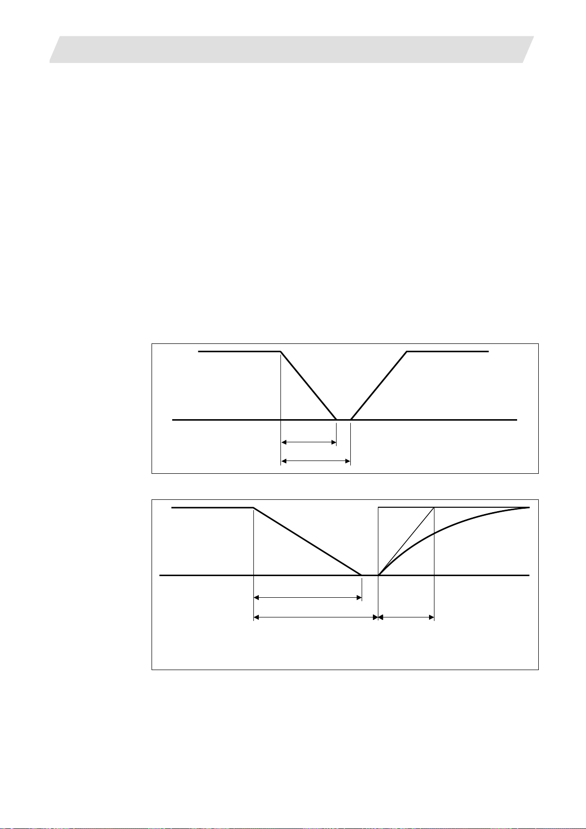
6. Interpolation Functions
A
6.1 Positioning (Rapid Traverse)
(Note 4) Rapid traverse (G00) deceleration check
There are two methods for the deceleration check at rapid traverse; commanded deceleration
method and in-position check method. Select a method with the parameter "#1193 inpos".
■ When "inpos" = "1"
Upon completion of the rapid traverse (G00), the next block will be executed after confirming that
the remaining distances for each axis are below the fixed amounts. (Refer to following drawing.)
The confirmation of the remaining distance should be done with the imposition width, L
setting value for the servo parameter "#2224 SV 024".
The purpose of checking the rapid feedrate is to minimize the time it takes for positioning. The
bigger the setting value for the servo parameter "#2224 SV024", the longer the reduced time is, but
the remaining distance of the previous block at the starting time of the next block also becomes
larger, and this could become an obstacle in the actual processing work. The check for the
remaining distance is done at set intervals. Accordingly, it may not be possible to get the actual
amount of time reduction for positioning with the setting value SV 024.
■ When "inpos" = "0"
Upon completion of the rapid traverse (G00), the next block will be executed after the deceleration
check time (Td) has elapsed. The deceleration check time (Td) is as follows, depending on the
acceleration/deceleration type.
(1) Linear acceleration/linear deceleration........................................ Td = Ts + α
. L R is the
R
Previous block
Ts
Td
Ts : Acceleration/decelerat ion
time constant
Td : Deceleration check time
Td = Ts + (0 ~ 14ms)
Next block
(2) Exponential acceleration/linear deceleration............................... Td = 2 × Ts + α
Previous block Next block
2 × Ts
Td
Ts
cceleration/deceleration
Ts :
time constant
Td : Deceleration check time
Td = 2 × Ts + (0 ~ 14ms)
36
Page 51

6. Interpolation Functions
6.1 Positioning (Rapid Traverse)
(3) Exponential acceleration/exponential deceleration ..................... Td = 2 × Ts + α
Previous block Next block
Ts
Td
Where Ts is the acceleration time constant, α = 0 to 14ms
The time required for the deceleration check during rapid traverse is the longest among the rapid
traverse deceleration check times of each axis determined by the rapid traverse
acceleration/deceleration time constants and by the rapid traverse acceleration/deceleration mode of
the axes commanded simultaneously.
Ts : Acceleration/decelerat ion
time constant
Td : Deceleration check time
Td = 2 × Ts + (0 ~ 14ms)
37
Page 52
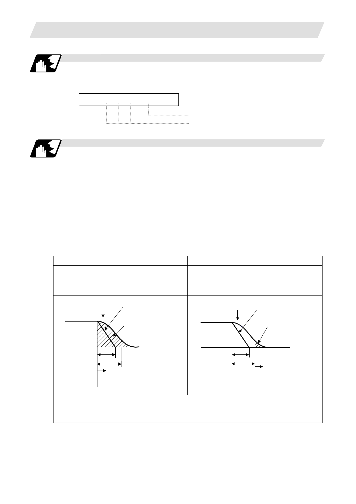
6. Interpolation Functions
Programmable in-position width command for positioning
This command commands the in-position width for the positioning command from the machining
program.
G00 X__ Y__ Z__ , I__ ;
Operation during in-position check
Execution of the next block starts after confirming that the position error amount of the positioning
(rapid traverse: G00) command block and the block that carries out deceleration check with the
linear interpolation (G01) command is less than the in-position width issued in this command.
The in-position width in this command is valid only in the command block, so the deceleration
check method set in base specification parameter "#1193 inpos" is used for blocks that do not have
the in-position width command.
When there are several movement axes, the system confirms that the position error amount of
each movement axis in each part system is less than the in-position width issued in this command
before executing the next block.
The differences of when the in-position check is validated with the parameter (base specification
parameter "#1193 inpos" set to 1; refer to next page for in-position width) and when validated with
this command are shown in the following drawing.
Differences between in-position check with this command and in-position check with parameter
6.1 Positioning (Rapid Traverse)
In-position width
Positioning coordinate value of each axis
In-position check with ",I" address command In-position check with parameter
After starting deceleration of the command
system, the position error amount and
commanded in-position width are compared.
After starting deceleration of the command
system, the servo system's position error amount
and the parameter setting value (in-position
width) are compared.
Block being
executed
Servo
Ts
Start of in-position
check with ",I" address command
Command
In-position width
(Error amount of command
end point and machine
position)
Td
Block being
executed
Servo
Ts
Td
Command
In-position width
(Servo system position
error amount)
Start of in-position
check with parameter
Ts : Acceleration/deceleration time constant
Td : Deceleration check time
Td = Ts + (0 to 14ms)
38
Page 53

6. Interpolation Functions
In-position width setting
When the servo parameter "#2224 SV024" setting value is smaller than the setting value of the G0
in-position width "#2077 G0inps" and the G1 in-position width "#2078 G1inps", the in-position
check is carried out with the G0 in-position width and the G1 in-position width.
In-position check using the
"G0inps" value
6.1 Positioning (Rapid Traverse)
Command to motor
Outline of motor movement
G0 in-position
SV024
A stop is judged here.
In-position check using the
"G1inps" value
When the SV024 value is larger, the in-position check is completed when the error amount is
smaller than the SV024 setting value.
The in-position check method depends on the method set in the deceleration check parameter.
(Note 1) When the in-position width (programmable in-position check width) is set in the machining program,
either the in-position width set with the parameter (SV024, G0inps, G1inps) or that set in the
program, whichever larger, is applied when performing an in-position check.
(Note 2) When the SV024 setting value is larger than the G0 in-position width/G1 in-position width, the
in-position check is carried out with the SV024 value.
(Note 3) When the error detect is ON, the in-position check is forcibly carried out.
Command to motor
Outline of motor movement
G1 in-position
SV024
A stop is judged here.
39
Page 54

6. Interpolation Functions
6.2 Linear Interpolation; G01
Function and purpose
This command is accompanied by coordinate words and a feedrate command.
It makes the tool move (interpolate) linearly from its present position to the end point specified by
the coordinate words at the speed specified by address F. In this case, the feedrate specified by
address F always acts as a linear speed in the tool nose center advance direction.
Command format
G01 X__ Y__ Z__ α__ F__ ,I__ ; (α represents additional axis)
X, Y, Z, α :Represents the coordinate value. An absolute position or
F :Feedrate (mm/min or °/min)
I :In-position width. A program error occurs if a decimal point
Detailed description
(1) Once this command is issued, the mode is maintained until another G function (G00, G02, G03,
G33) in the 01 group which changes the G01 mode is issued. Therefore, if the next command
is also G01 and if the feedrate is the same, all that is required to be done is to specify the
coordinate words. If no F command is given in the first G01 command block, program error
(P62) results.
(2) The feedrate for a rotary axis is commanded by
300
°/min)
(3) The G functions (G70 - G89) in the 09 group are cancelled (G80) by the G01 command.
6.2 Linear Interpolation
incremental position is indicated based on the state of G90/G91 at
that time.
command is issued. This is valid only in the commanded block. A
block that does not contain this address will follow the parameter
"#1193 inpos" settings.
°/min (decimal point position unit). (F300 =
40
Page 55

6. Interpolation Functions
Example of program
(Example 1) Cutting in the sequence of P
P
→ P1 is for tool positioning
0
P
2
6.2 Linear Interpolation
→ P2 → P3 → P4 → P1 at 300 mm/min feedrate
1
30
P
3
30
Y
X
P
1
20
P
0
20
P4
20
Unit: mm
Input setting unit: 0.001mm
G90 G00 X20000 Y20000 ;
G01 X20000 Y30000 F300
X30000 ;
X-20000 Y-30000 ;
X-30000 ;
P
0
P
1
P
2
P
3
P
4
→ P1
→ P2
→ P3
→ P4
→ P1
Programmable in-position width command for linear interpolation
This command commands the in-position width for the linear interpolation command from the
machining program.
The commanded in-position width is valid in the linear interpolation command only when carrying
out deceleration check.
• When the error detect switch is ON.
• When G09 (exact stop check) is commanded in the same block.
• When G61 (exact stop check mode) is selected.
G01 X__ Y__ Z__ F__ , I__ ;
(Note 1)
Refer to section "6.1 Positioning (rapid traverse); G00" for details on the in-position
check operation.
In-position width
Feedrate
Linear interpolation coordinate value of each axis
41
Page 56

6. Interpolation Functions
6.3 Plane Selection; G17, G18, G19
Function and purpose
The plane to which the movement of the tool during the circle interpolation (including helical
cutting) and tool radius compensation command belongs is selected.
By registering the basic three axes and the corresponding parallel axis as parameters, a plane can
be selected by two axes that are not the parallel axis. If the rotary axis is registered as a parallel
axis, a plane that contains the rotary axis can be selected.
The plane selection is as follows:
• Plane that executes circular interpolation (including helical cutting)
• Plane that executes tool radius compensation
• Plane that executes fixed cycle positioning.
Command format
G17 ;
G18 ;
G19 ;
X, Y and Z indicate each coordinate axis or the parallel axis.
Parameter entry
Table 1 Example of plane selection parameter entry
#1026 to 1028
base_I,J,K
(ZX plane selection)
(YZ plane selection)
(XY plane selection)
#1029 to 1039
aux_I,J,K
6.3 Plane Selection
I X U
J Y
K Z V
As shown in the above example, the basic axis and its parallel axis can be registered.
The basic axis can be an axis other than X, Y and Z.
Axes that are not registered are irrelevant to the plane selection.
42
Page 57

6. Interpolation Functions
Plane selection system
In Table 1,
I is the horizontal axis for the G17 plane or the vertical axis for the G18 plane
J is the vertical axis for the G17 plane or the horizontal axis for the G19 plane
K is the horizontal axis for the G18 plane or the vertical axis for the G19 plane
In other words,
G17 ..... IJ plane
G18 ..... KI plane
G19 ..... JK plane
(1) The axis address commanded in the same block as the plane selection (G17, G18, G19)
determines which basic axis or parallel axis is used for the plane selection.
For the parameter registration example in Table 1.
G17X__Y__ ; XY plane
G18X__V__ ; VX plane
G18U__V__ ; VU plane
G19Y__Z__ ; YZ plane
G19Y__V__ ; YV plane
(2) The plane will not changeover at a block where a plane selection G code (G17, G18, G19) is
not commanded.
G17X__Y__ ; XY plane
(3) If the axis address is omitted in the block where the plane selection G code (G17, G18, G19) is
commanded, it will be viewed as though the basic three axes address has been omitted.
For the parameter registration example in Table 1.
G17 ; XY plane
G17U__ ; UY plane
G18U__ ; ZU plane
G18V__ ; VX plane
G19Y__ ; YZ plane
G19V__ ; YV plane
(4) The axis command that does not exist in the plane determined by the plane selection G code
(G17, G18, G19) is irrelevant to the plane selection.
For the parameter registration example in Table 1.
G17U__Z__ ;
(5) If the above is commanded, the UY plane will be selected, and Z will move regardless of the
plane.
If the basic axis and parallel axis are commanded in duplicate in the same block as the plane
selection G code (G17, G18, G19), the plane will be determined in the priority order of basic
axis and parallel axis.
For the parameter registration example in Table 1.
G17U__Y__W__-;
If the above is commanded, the UY plane will be selected, and W will move regardless of the plane.
(Note 1)
The plane set with parameter "#1025 I_plane" will be selected when the power is turned
ON or reset.
Y__Z__ ; XY plane (plane does not change)
6.3 Plane Selection
43
Page 58

6. Interpolation Functions
6.4 Circular Interpolation; G02, G03
Function and purpose
These commands serve to move the tool along an arc.
Command format
G02 (G03) X__ Y__ I__ J__ K__ F__;
G02 : Clockwise (CW)
G03 : Counterclockwise (CCW)
X, Y : End point
I, J : Arc center
F : Feedrate
For the arc command, the arc end point coordinates are assigned with addresses X, Y (or Z, or
parallel axis X, Y, Z), and the arc center coordinate value is assigned with addresses I, J (or K).
Either an absolute value or incremental value can be used for the arc end point coordinate value
command, but the arc center coordinate value must always be commanded with an incremental
value from the start point.
The arc center coordinate value is commanded with an input setting unit. Caution is required for the
arc command of an axis for which the input command value differs. Command with a decimal point
to avoid confusion.
6.4 Circular Interpolation
44
Page 59

6. Interpolation Functions
Detailed description
(1) G02 (or G03) is retained until another G command (G00, G01 or G33) in the 01 group that
changes its mode is issued.
The arc rotation direction is distinguished by G02 and G03.
G02 Clockwise (CW)
G03 Counterclockwise (CCW)
6.4 Circular Interpolation
Y
G02
G17(X-Y)plane
G03
X
G02
X
G18(Z-X)plane
X
G03
Z
Z
G2
G2
G3
G3
G3
G2
Z
G02
G19(Y-Z)plane
Y
G03
Y
(2) An arc which extends for more than one quadrant can be executed with a single block
command.
(3) The following information is needed for circular interpolation.
(a) Plane selection................... : Is there an arc parallel to one of the XY, ZX or YZ planes?
(b) Rotation direction ............... : Clockwise (G02) or counterclockwise (G03)?
(c) Arc end point coordinates... : Given by addresses X, Y, Z
(d) Arc center coordinates ....... : Given by addresses I, J, K (incremental commands)
(e) Feed rate ............................ : Given by address F
45
Page 60

6. Interpolation Functions
r
A
r
Example of program
(Example 1)
6.4 Circular Interpolation
Feedrate
F = 500mm/min
X axis
Y axis
+Y
Circle cente
J = 50mm
+X
Start point/end point
G02 J50000 F500 ; Circle command
(Example 2)
Y axis
+Y
X axis
Feedrate
F = 500mm/min
rc cente
J = 50mm
Start point
End point
X50 Y50mm
+X
G91 G02 X50000 Y50000 J50000 F500 ; 3/4 command
46
Page 61
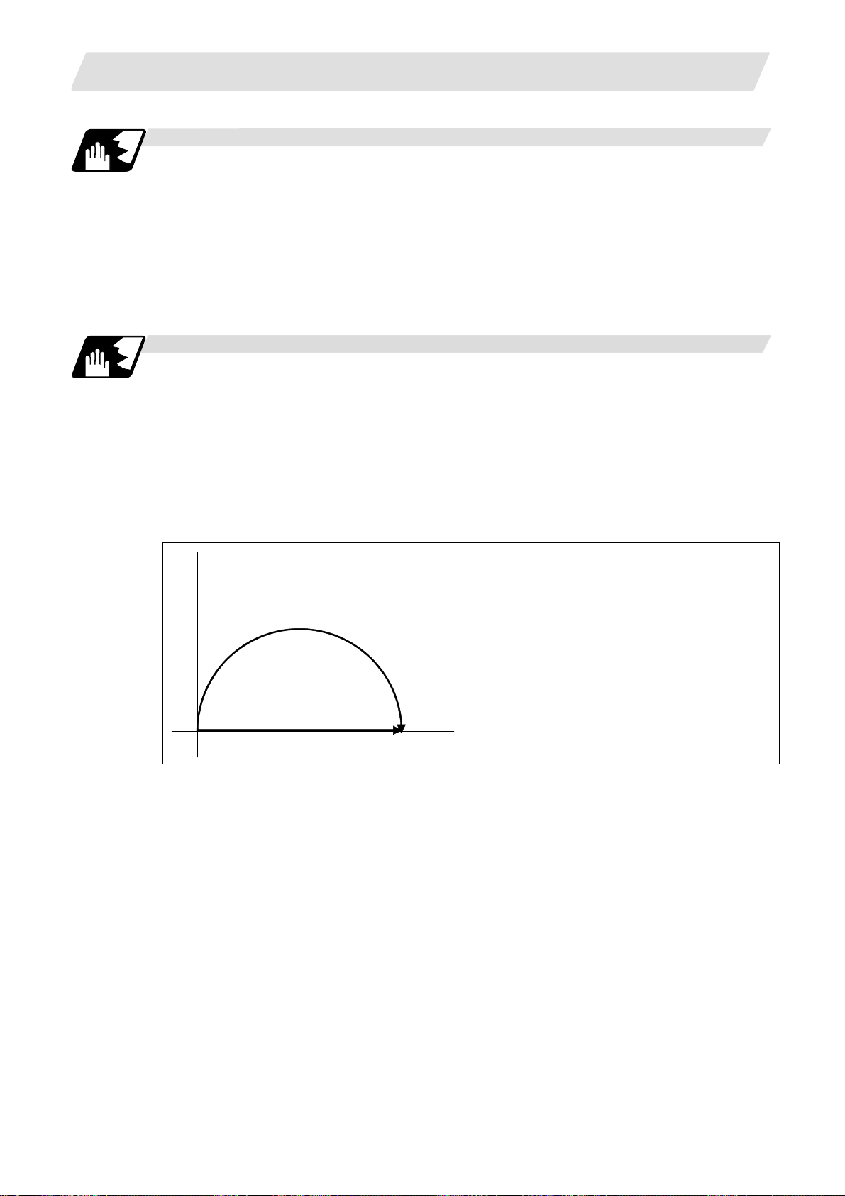
6. Interpolation Functions
Plane selection
The planes in which the arc exists are the following three planes (refer to the detailed drawings),
and are selected with the following method.
XY plane
G17; Command with a (plane selection G code)
ZX plane
G18; Command with a (plane selection G code)
YZ plane
G19; Command with a (plane selection G code)
Change into linear interpolation command
Program error (P33) will occur when the center and radius are not designated at circular command.
When the parameter "#11029 Arc to G1 no Cent (Change command from arc to linear when no arc
center designation)" is set, the linear interpolation can be applied to terminal coordinates value for
only the block. However, a modal is the circular modal.
This function is not applied to a circular command by a geometric function.
(Example) The parameter "#11029 Arc to G1 no Cent (Change command from arc to linear when
no arc center designation)" = "1"
6.4 Circular Interpolation
N1
G90 X0 Y0 ;
N1 G02 X20. I10. F500 ;
N2 G00 X0
N3 G02 X20. F500 ;
M02 ;
;
… (a)
… (b)
N3
0
20
(a) The circular interpolation (G02) is executed because there is a center command.
(b) The linear interpolation (G01) is executed because there is no center and radius command.
47
Page 62

6. Interpolation Functions
A
r
Precautions for circular interpolation
(1) The terms "clockwise" (G02) and "counterclockwise" (G03) used for arc operations are
defined as a case where in a right-hand coordinate system, the negative direction is viewed
from the position direction of the coordinate axis which is at right angles to the plane in
question.
(2) When all the end point coordinates are omitted or when the end point is the same position as
the start point, a 360° arc (full circle) is commanded when the center is commanded using I, J
and K.
(3) The following occurs when the start and end point radius do not match in an arc command :
(a) Program error (P70) results at the arc start point when error ΔR is greater than parameter
"#1084 RadErr".
(G91) G02X9.899I 5. ;
larm stop
6.4 Circular Interpolation
#1084 RadErr parameter value 0.100
Start point radius = 5.000
End point radius = 4.899
Error
ΔR = 0.101
Start point
Start point radius
Cente
End point radius
End point
ΔR
(b) Spiral interpolation in the direction of the commanded end point results when error ΔR is
less than the parameter value.
(G91) G02X9.9I 5. ;
Start point
Start point radius
Center
End point radius
End point
Spiral interpolation
#1084 RadErr parameter value 0.100
Start point radius = 5.000
End point radius = 4.900
ΔR = 0.100
Error
ΔR
The parameter setting range is from 0.001mm to 1.000mm.
48
Page 63

6. Interpolation Functions
A
A
r
6.5 R-specified Circular Interpolation; G02, G03
Function and purpose
Along with the conventional circular interpolation commands based on the arc center coordinate (I,
J, K) designation, these commands can also be issued by directly designating the arc radius R.
Command format
G02 (G03) X__ Y__ R__ F__ ;
X : X axis end point coordinate
Y : Y axis end point coordinate
R : Arc radius
F : Feedrate
The arc radius is commanded with an input setting unit. Caution is required for the arc command of
an axis for which the input command value differs. Command with a decimal point to avoid
confusion.
Detailed description
The arc center is on the bisector line which is perpendicular to the line connecting the start and end
points of the arc. The point, where the arc with the specified radius whose start point is the center
intersects the perpendicular bisector line, serves as the center coordinates of the arc command.
If the R sign of the commanded program is plus, the arc is smaller than a semisphere; if it is minus,
the arc is larger than a semisphere.
6.5 R-specified Circular Interpolation
rc path when
R sign is minus
Start point
02
Center
point
Center point
L
r
rc path when
R sign is plus
Cente
01
End point
point
The following condition must be met with an R-specified arc interpolation command:
L/(2xr) ≤ 1 An error will occur when L/2 - r > (parameter : #1084 RadErr)
Where L is the line from the start point to end point.
When the R specification and I, J, K specification are contained in the same block, the R
specification has priority in processing.
When the R specification and I, J, K specification are contained in the same block, the R
specification has priority in processing.
The plane selection is the same as for the I, J, K-specified arc command.
49
Page 64

6. Interpolation Functions
Example of program
(Example 1)
(Example 2)
(Example 3)
(Example 4)
G02 Xx
G03 Zz
G02 Xx
Yy1 Rr1 Ff1 ; XY plane R-specified arc
1
Xx1 Rr1 Ff1 ; ZX plane R-specified arc
1
Yy1 Ii1 Jj1 Rr1 Ff1 ; XY plane R-specified arc
1
G17 G02 Ii
6.5 R-specified Circular Interpolation
(When the R specification and I, J, (K)
specification are contained in the same block,
the R specification has priority in processing.)
Jj1 Rr1 Ff1 ; XY plane This is an R-specified arc, but as
1
this is a circle command, it is already
completed.
50
Page 65

6. Interpolation Functions
Circular center coordinate compensation
When "the error margin between the segment connecting the start and end points" and "the
commanded radius × 2" is less than the setting value because the required semicircle is not
obtained by calculation error in R specification circular interpolation, "the midpoint of segment
connecting the start and end points" is compensated as the circular center.
Set the setting value to the parameter "#11028 Tolerance Arc Cent (Tolerable correction value of
arc center error)".
(Ex.) "#11028 Tolerance Arc Cent" = "0.000 (mm)"
Setting value Tolerance value
Setting value< 0 0(Center error will not be interpolated)
Setting value= 0
Setting value> 0 Setting value
×minimum setting increment
2
6.5 R-specified Circular Interpolation
G90 X0 Y0 ;
N1 G02 X10. R5.000;
N1, N3
N
0
10
N2 G0 X0;
N3 G02 X10. R5.001;
N4 G0 X0;
N5 G02 X10. R5.002;
N6 G0 X0;
M02 ;
… (a)
… (b)
(a) Compensate the center coordinate: Same as N1 path
(b) Do not compensate the center coordinate: Inside path a little than N1
Calculation error margin compensation allowance value: 0.002 mm
Segment connecting the start and end paints: 10.000
N3: Radius × 2 = 10.002 "Error 0.002 -> Compensate"
N5: Radius × 2 = 10.004 "Error 0.004 -> Do not compensate"
Therefore, this example is shown in the above figure.
51
Page 66

6. Interpolation Functions
6.6 Helical Interpolation ; G17 to G19, G02, G03
Function and purpose
While circular interpolating with G02/G03 within the plane selected with the plane selection G code
(G17, G18, G19), the 3rd axis can be linearly interpolated.
Normally, the helical interpolation speed is designated with the tangent speed F' including the 3rd
axis interpolation element as shown in the lower drawing of Fig. 1. However, when designating the
arc plane element speed, the tangent speed F on the arc plane is commanded as shown in the
upper drawing of Fig. 1.
The NC automatically calculates the helical interpolation tangent speed F' so that the tangent
speed on the arc plane is F.
6.6 Helical Interpolation
Start point
Y
End point
X
Z
Y
End point
X
F
F’
Start point
Fig. 1 Designation of helical interpolation speed
Command format
G17 G02 (G03) Xx1 Yy1 Zz1 Ii1 Jj1 Pp1 Ff1 ; Helical interpolation command (Specify arc center)
G17 G02 (G03) Xx
Yy2 Zz2 Rr2 Ff2 ; Helical interpolation command (Specify radius (R))
2
G17(G18, G19) : Plane selection (G17: XY plane, G18: ZX plane, G19: YZ plane)
G02(G03) : Arc rotation direction
Xx
Yy1 Xx2 Yy2 : Arc end point coordinate
1
Zz
Zz2 : Linear axis end point coordinate
1
Ii
Jj1 : Arc center coordinate
1
Pp
: Pitch No.
1
Ff
Ff2 : Feedrate
1
Rr
: Arc radius
2
The arc center coordinate and arc radius are commanded with an input setting input. Caution is
required for the helical interpolation command of an axis for which the input command value differs.
Command with a decimal point to avoid confusion.
Absolute or incremental values can be assigned for the arc end point coordinates and the end point
coordinates of the linear axis, but incremental values must be assigned for the arc center
coordinates.
52
Page 67

6. Interpolation Functions
The arc plane element speed designation and normal speed designation can be selected with the
parameter.
#1235 set07/bit0 Meaning
1 Arc plane element speed designation is selected.
0 Normal speed designation is selected.
Z axis
Normal speed designation
Y axis
l
P1time
Z1
Second time
First time
6.6 Helical Interpolation
Y
θ
θ
e
End point
θ
s
X
Start point
X axis
(1) This command should be issued with a linear axis (multiple axes can be commanded) that
does not contain a circular axis in the circular interpolation command combined.
(2) For feedrate F, command the X, Y Z axis composite element directions speed.
(3) Pitch l is obtained with the following expression.
Z1
l
=
(2π • P1 + θ) / 2π
= θE - θs = tan
θ
-1
ye
xe
- tan-1
ys
(0 ≤ θ < 2π)
xs
Where xs, ys are the start point coordinates from the arc center
xe, ye are the end point coordinates from the arc center
(4) If pitch No. is 0, address P can be omitted.
(Note) The pitch No. P command range is 0 to 9999.
The pitch No. designation (P command) cannot be made with the R-specified arc.
(5) Plane selection
The helical interpolation arc plane selection is determined with the plane selection mode and
axis address as for the circular interpolation. For the helical interpolation command, the plane
where circular interpolation is executed is commanded with the plane selection G code (G17,
G18, G19), and the 2 circular interpolation axes and linear interpolation axis (axis that
intersects with circular plane) 3 axis addresses are commanded.
XY plane circular, Z axis linear
Command the X, Y and Z axis addresses in the G02 (G03) and G17 (plane selection
G code) mode.
ZX plane circular, Y axis linear
Command the X, Y and Z axis addresses in the G02 (G03) and G18 (plane selection
G code) mode.
YZ plane circular, X axis linear
Command the X, Y and Z axis addresses in the G02 (G03) and G19 (plane selection
G code) mode.
53
Page 68
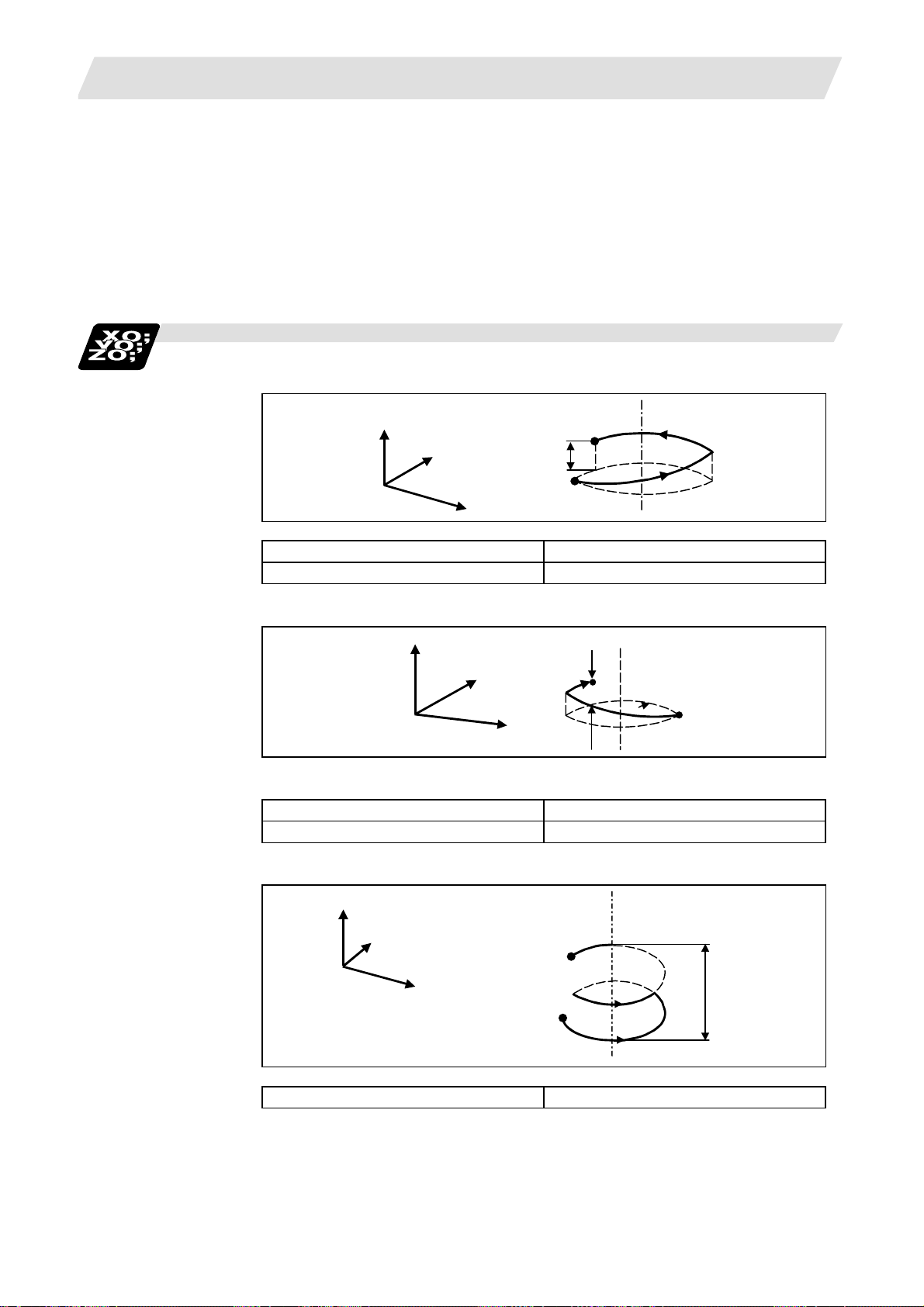
6. Interpolation Functions
Z
r
The plane for an additional axis can be selected as with circular interpolation.
UY plane circular, Z axis linear
In addition to the basic command methods above, the command methods following the
program example can be used. Refer to the section "6.3 plane selection" for the arc planes
selected with these command methods.
Example of program
(Example 1)
6.6 Helical Interpolation
Command the U, Y and Z axis addresses in the G02 (G03) and G19 (plane selection
G code) mode.
Z axis
Y axis
X axis
z
1
G17 ; XY plane
G03 Xx1 Yy1 Zz1 Ii1 Jj1 P0 Ff1 ; XY plane arc, Z axis linear
(Note) If pitch No. is 0, address P can be omitted.
axis
Y axis
X axis
z
1
1
(Example 2)
G17 ; XY plane
G02 Xx1 Yy1 Zz1 Rr1 Ff1 ; XY plane arc, Z axis linear
(Example 3)
Z axis
Y axis
U axis
z1
G17 G03 Uu
Yy1 Zz1 Ii1 Jj1 P2 Ff1 ; UY plane arc, Z axis linear
1
54
Page 69

6. Interpolation Functions
x
(Example 4)
6.6 Helical Interpolation
U axisXaxis
Z axis
u1
1
z1
G18 G03 Xx
Uu1 Zz1 Ii1 Kk1 Ff1 ; ZX plane arc, U axis linear
1
(Note) If the same system is used, the standard axis will perform circular interpolation
and the additional axis will perform linear interpolation.
(Example 5)
G18 G02 Xx
;
Ff
1
Uu1 Yy1 Zz1 Ii1 Jj1 Kk1
1
ZX plane arc, U axis, Y axis linear
(The J command is ignored)
(Note) Two or more axes can be designated for the linear interpolation axis.
Arc plane element speed designation
If arc plane element speed designation is selected, the F command will be handled as modal data
in the same manner as the normal F command. This will also apply to the following G01, G02 and
G03 commands.
For example, the program will be as follows.
(Example)
G17 G91 G02 X10. Y10. Z-4. I10, F100 ; Helical interpolation at speed at which arc plane
element is F100
G01 X20. ; Linear interpolation at F100
G02 X10. Y-10. Z4. J10. ; Helical interpolation at speed at which arc plane
element is F100
G01 Y-40. F120 ; Linear interpolation at F120
G02 X-10. Y-10. Z-4. I10. ; Helical interpolation at speed at which arc plane
element is F120
G01 X-20. ; Linear interpolation at F120
When the arc plane element speed designation is selected, only the helical interpolation speed
command is converted to the speed commanded with the arc plane element. The other linear and
arc commands operate as normal speed commands.
(1) The actual feedrate display (Fc) indicates the tangent element of the helical interpolation.
(2) The modal value speed display (FA) indicates the command speed.
(3) The speed data acquired with API functions follows the Fc and FA display.
(4) This function is valid only when feed per minute (asynchronous feed: G94) is selected. If feed
per revolution (synchronous feed: G95) is selected, the arc plane element speed will not be
designated.
(5) The helical interpolation option is required to use this function.
55
Page 70

6. Interpolation Functions
6.7 Thread Cutting
6.7.1 Constant Lead Thread Cutting; G33
Function and purpose
The G33 command exercises feed control over the tool which is synchronized with the spindle
rotation and so this makes it possible to conduct constant-lead straight thread-cutting and tapered
thread-cutting. Multiple thread screws, etc., can also be machined by designating the thread cutting
angle.
Command format
G33 Z__(X__ Y__ α__) F__ Q__ ; (Normal lead thread cutting commands)
Z (X Y α) : Thread end point
F : Lead of long axis (axis which moves most) direction
Q : Thread cutting start shift angle, (0.000 to 360.000°)
G33 Z__(X__ Y__ α__) E__ Q__ ; (Precision lead thread cutting commands)
Z (X Y α) : Thread end point
E : Lead of long axis (axis which moves most) direction
Q : Thread cutting start shift angle, (0.000 to 360.000°)
Detailed description
(1) The E command is also used for the number of ridges in inch thread cutting, and whether the
ridge number or precision lead is to be designated can be selected by parameter setting.
(Precision lead is designated by setting the parameter "#1229 set 01/bit 1" to 1.)
(2) The lead in the long axis direction is commanded for the taper thread lead.
6.7 Thread Cutting
Z
LZ
a
LX
When a<45°, the lead is LZ.
When a>45°, the lead is LX.
When a=45°, the lead can be in either LX or LZ.
Tapered thread section
X
56
Page 71

6. Interpolation Functions
Thread cutting metric input
6.7 Thread Cutting
Input unit
system
Command
address
Minimum
command
unit
Command
range
Input unit
system
Command
address
Minimum
command
unit
Command
range
Input unit
system
Command
address
Minimum
command
unit
Command
range
Input unit
system
Command
address
Minimum
command
unit
Command
range
B (0.001mm) C (0.0001mm)
F (mm/rev) E (mm/rev) E (ridges/inch) F (mm/rev) E (mm/rev) E (ridges/inch)
1(=1.000)
(1.=1.000)
0.001~
999.999
F (mm/rev) E (mm/rev) E (ridges/inch) F (mm/rev) E (mm/rev) E (ridges/inch)
1(=1.00000)
(1.=1.00000)
0.00001~
999.99999
1(=1.00000)
(1.=1.00000)
0.00001~
999.99999
D (0.00001mm) E (0.000001mm)
1(=1.0000000)
(1.=1.0000000)
0.0000001~
999.9999999
1(=1.00)
(1.=1.00)
0.03~999.99
1(=1.0000)
(1.=1.0000)
0.0255~
999.9999
1(=1.0000)
(1.=1.0000)
0.0001~
999.9999
1(=1.000000)
(1.=1.000000)
0.000001~
999.999999
1(=1.000000)
(1.=1.000000)
0.000001~
999.999999
1(=1.00000000)
(1.=1.00000000)
0.00000001~
999.99999999
1(=1.000)
(1.=1.000)
0.026~
999.999
1(=1.00000)
(1.=1.00000)
0.02541~
999.99999
Thread cutting inch input
B (0.0001inch) C (0.00001inch)
F (inch/rev) E (inch/rev) E (ridges/inch) F (inch/rev) E (inch/rev) E (ridges/inch)
1(=1.0000)
(1.=1.0000)
0.0001~99.9999
F (inch/rev) E (inch/rev) E (ridges/inch) F (inch/rev) E (inch/rev) E (ridges/inch)
1(=1.000000)
(1.=1.000000)
0.000001~
99.999999
1(=1.000000)
(1.=1.000000)
0.000001~
39.370078
D (0.000001inch) E (0.0000001inch)
1(=1.00000000)
(1.=1.00000000)
0.00000001~
39.37007874
1(=1.0000)
(1.=1.0000)
0.0101~
9999.9999
1(=1.000000)
(1.=1.000000)
0.010001~
9999.999999
1(=1.00000)
(1.=1.00000)
0.00001~
99.99999
1(=1.0000000)
(1.=1.0000000)
0.0000001~
99.9999999
1(=1.0000000)
(1.=1.0000000)
0.0000001~
39.3700787
1(=1.000000000)
(1.=1.000000000)
0.000000001~
39.370078740
1(=1.00000)
(1.=1.00000)
0.01001~
9999.99999
1(=1.0000000)
(1.=1.0000000)
0.0100001~
9999.9999999
(Note 1) It is not possible to assign a lead where the feed rate as converted into per-minute
feed exceeds the maximum cutting feed rate.
(3) The constant surface speed control function should not be used for taper thread cutting
commands or scrolled thread cutting commands.
(4) The thread cutting command waits for the “single rotation sync“ signal of the rotary encoder
and starts movement. Make sure to carry out timing-synchronization between part systems
before issuing a thread cutting command with multiple part systems.
For example, with the 1-spindle specifications with two part systems, if one part system issues
a thread cutting command during ongoing thread cutting by another part system, the
movement will start without waiting for the rotary encoder “single rotation sync” signal causing
an illegal operation.
(5) The spindle speed should be kept constant throughout from the rough cutting until the
finishing.
57
Page 72

6. Interpolation Functions
(6) If the feed hold function is employed during thread cutting to stop the feed, the thread ridges
will lose their shape. For this reason, feed hold does not function during thread cutting.
Note that this is valid from the time the thread cutting command is executed to the time the axis
moves.
If the feed hold switch is pressed during thread cutting, block stop will result at the end point of
the block following the block in which thread cutting is completed (no longer G33 mode).
(7) The converted cutting feedrate is compared with the cutting feed clamp rate when thread
cutting starts, and if it is found to exceed the clamp rate, an operation error will result.
(8) In order to protect the lead during thread cutting, a cutting feed rate which has been converted
may sometimes exceed the cutting feed clamp rate.
(9) An illegal lead is normally produced at the start of the thread and at the end of the cutting
because of servo system delay and other such factors.
Therefore, it is necessary to command a thread length which is determined by adding the
illegal lead lengths to the required thread length.
(10) The spindle speed is subject to the following restriction :
1 ≤ R ≤
Where R ≤ Permissible speed of encoder (r/min)
(11) When the thread lead is extremely large to the maximum cutting feedrate enough to satisfy
"R<1" in the formula of (10) above, the program error (P93) may occur.
(12) Though dry run is valid for thread cutting, the feed rate based on dry run is not synchronized
with the spindle rotation.
The dry run signal is checked at the start of thread cutting and any switching during thread
cutting is ignored.
(13) Synchronous feed applies for the thread cutting commands even with an asynchronous feed
command (G94).
(14) Spindle override and cutting feed override are invalid and the speeds are fixed to 100% during
thread cutting.
(15) When a thread cutting is commanded during tool radius compensation, the compensation is
temporarily canceled and the thread cutting is executed.
(16) When the mode is switched to another automatic mode while G33 is executed, the following
block which does not contain a thread cutting command is first executed and then the
automatic operation stops.
(17) When the mode is switched to the manual mode while G33 is executed, the following block
which does not contain a thread cutting command is first executed and then the automatic
operation stops.
In the case of a single block, the following block which does not contain a thread cutting
command (when G33 mode is cancelled) is first executed and then the automatic operation
stops.
Note that automatic operation will stop immediately if the mode is switched before the
G33-commanded axis starts moving.
(18) The handle interruption for automatic operation is valid while thread cutting.
(19) The thread cutting start shift angle is not a modal. If there is no Q command with G33, this will
be handled as "Q0".
(20) If a value more than 360.000 is commanded with G33 Q, the program error (P35) will occur.
(21) G33 cuts one row with one cycle. To cut two rows, change the Q value, and issue the same
command.
Maximum feedrate
Thread lead
R : Spindle speed (r/min)
Thread lead : mm or inches
Maximum feedrate : mm/min or inch/mm (This is subject to the restrictions imposed
by the machine specifications).
6.7 Thread Cutting
58
Page 73

6. Interpolation Functions
Example of program
6.7 Thread Cutting
Z
10
50
10
Y
X
X
N110 G90 G0 X-200. Y-200. S50 M3 ;
N111 Z110. ;
The spindle center is positioned to the workpiece
center, and the spindle rotates in the forward direction.
N112 G33 Z40. F6.0 ; The first thread cutting is executed.
Thread lead = 6.0mm
N113 M19 ; Spindle orientation is executed with the M19
command.
N114 G0X-210. ; The tool is evaded in the X axis direction.
N115 Z110. M0 ; The tool rises to the top of the workpiece, and the
program stops with M00.
Adjust the tool if required.
N116 X-200. ;
Preparation for second thread cutting is done.
M3 ;
N117 G04 X5.0 ; Command dwell to stabilize the spindle rotation if
necessary.
N11 G33 Z40. ; The second thread cutting is executed.
59
Page 74

6. Interpolation Functions
6.7.2 Inch Thread Cutting; G33
Function and purpose
If the number of ridges per inch in the long axis direction is assigned in the G33 command, the feed
of the tool synchronized with the spindle rotation will be controlled, which means that constant-lead
straight thread-cutting and tapered thread-cutting can be performed.
Command format
G33 Z__ E__ Q__ ;
Z : Thread cutting direction axis address (X, Y, Z, α) and thread length
E : Number of ridges per inch in direction of long axis (axis which moves
Q : Thread cutting start shift angle, 0 to 360°.
Detailed description
(1) The number of ridges in the long axis direction is assigned as the number of ridges per inch.
(2) The E code is also used to assign the precision lead length, and whether the ridge number of
precision lead length is to be designated can be selected by parameter setting. (The number of
ridges is designated by setting the parameter "#1229 set01/bit1" to 0.)
(3) The E command value should be set within the lead value range when the lead is converted.
(4) The other matters are the same as uniform lead thread cutting.
6.7 Thread Cutting
most) (decimal point command can also be assigned)
60
Page 75

6. Interpolation Functions
Example of program
Thread lead ..... 3 threads/inch (= 8.46666 ...)
When programmed with δ
δ
= 10mm using metric input
2
= 10mm,
1
Z
6.8 Unidirectional Positioning
δ
1
50.0mm
δ
2
N210 G90 G0X-200. Y-200. S50M3;
N211 Z110.;
N212 G91 G33 Z-70.E3.0; (First thread cutting)
N213 M19;
N214 G90 G0X-210.;
N215 Z110.M0;
M3;
N217 G04 X2.0;
N218 G91 G33 Z-70.; (Second thread cutting)
6.8 Unidirectional Positioning; G60
Function and purpose
The G60 command can position the tool at a high degree of precision without backlash error by
locating the final tool position from a single determined direction.
Y
X
X
N216 X-200.;
61
Page 76

6. Interpolation Functions
Command format
G60 X__ Y__ Z__ α__ ;
α : Optional axis
Detailed description
(1) The creep distance for the final positioning as well as the final positioning direction is set by
parameter.
(2) After the tool has moved at the rapid traverse rate to the position separated from the final
position by an amount equivalent to the creep distance, it move to the final position in
accordance with the rapid traverse setting where its positioning is completed.
6.8 Unidirectional Positioning
G60a
-
Start point
Stop once
Positioning position
[Final advance direction]
End point
[G60creep distance]
G60-a
Start point
+
(3) The above positioning operation is performed even when Z axis commands have been
assigned for Z axis cancel and machine lock. (Display only)
(4) When the mirror image function is ON, the tool will move in the opposite direction as far as the
intermediate position due to the mirror image function but the operation within the creep
distance during its final advance will not be affected by mirror image.
(5) The tool moves to the end point at the dry run speed during dry run when the G0 dry run
function is valid.
(6) Feed during creep distance movement with final positioning can be stopped by resetting,
emergency stop, interlock, feed hold and rapid traverse override zero.
The tool moves over the creep distance at the rapid traverse setting. Rapid traverse override is
valid.
(7) Uni-directional positioning is not performed for the drilling axis during drilling fixed cycles.
(8) Uni-directional positioning is not performed for shift amount movements during the fine boring
or back boring fixed cycle.
(9) Normal positioning is performed for axes whose creep distance has not been set by
parameter.
(10) Uni-directional positioning is always a non-interpolation type of positioning.
(11) When the same position (movement amount of zero) has been commanded, the tool moves
back and forth over the creep distance and is positioned at its original position from the final
advance direction.
(12) Program error (P61) results when the G60 command is assigned with an NC system which
has not been provided with this particular specification.
62
Page 77

6. Interpolation Functions
6.9 Cylindrical Interpolation; G07.1
Function and purpose
This function develops a shape with a cylindrical side (shape in cylindrical coordinate system) into
a plane. When the developed shape is programmed as the plane coordinates, that is converted into
the linear axis and rotation axis movement in the cylindrical coordinates and the contour is
controlled during machining.
6.9 Cylindrical Interpolation ; G07.1
Y
X
r
Z
B
As programming can be carried out with a shape with which the side on the cylinder is developed,
this is effective for machining cylindrical cams, etc. When programmed with the rotation axis and its
orthogonal axis, slits, etc., can be machined on the cylinder side.
Develop-
ment
0°
2πr
360°
63
Page 78

6. Interpolation Functions
Command format
G07.1 C__ ; (Cylindrical interpolation mode start/cancel)
C : Cylinder radius value
(Note) The above format applies when the name of the rotation axis is "C". If the name is not "C",
command the name of the rotation axis being used instead of "C".
(1) The coordinates commanded in the interval from the start to cancellation of the cylindrical
interpolation mode will be the cylindrical coordinate system.
G07.1 C Cylinder radius value;
:
:
:
G07.1 C0 ; Cylindrical interpolation mode cancel
6.9 Cylindrical Interpolation ; G07.1
• Radius value ≠ 0: Cylindrical interpolation mode start
• Radius value = 0: Cylindrical interpolation mode cancel
Cylindrical interpolation mode start
(Cylindrical interpolation will start)
(The coordinate commands in this interval will be the
cylindrical coordinate system)
(Cylindrical interpolation will be canceled)
(2) G107 can be used instead of G07.1.
64
Page 79

6. Interpolation Functions
Detailed description
(1) Command G07.1 in an independent block. A program error (P33) will occur if this command is
issued in the same block as another G code.
(2) Program the rotation axis with an angle degree.
(3) Linear interpolation or circular interpolation can be commanded during the cylindrical
interpolation mode. Note that the plane selection command must be issued just before the
G07.1 block.
(4) The coordinates can be commanded with either an absolute command or incremental
command.
(5) Tool radius compensation can be applied on the program command. Cylindrical interpolation will
be executed on the path after tool radius compensation.
(6) Command the segment feed in the cylinder development with F. The F unit is mm/min or
inch/min.
(7) Cylindrical interpolation accuracy
In the cylindrical interpolation mode, the movement amount of the rotation axis commanded
with an angle is converted on the circle periphery, and after operating the linear and circular
interpolation between the other axes, the amount is converted into an angle again.
Thus, the actual movement amount may differ from the commanded value such as when the
cylinder radius is small.
Note that the error generated at this time is not cumulated.
6.9 Cylindrical Interpolation ; G07.1
(8) F command during cylindrical interpolation
As for the F command in the cylindrical interpolation mode, whether the previous F command
is used or not depends on that the mode just before G07.1 is the feed per minute command
(G94/G98) or feed per rotation command (G95/G99).
(a) When G94 is commanded just before G07.1
If there is no F command in the cylindrical interpolation, the previous F command feedrate
will be used.
The feedrate after the cylindrical interpolation mode is canceled will remain the F
command feedrate issued when the cylindrical interpolation mode was started or the final
F command feedrate set during cylindrical interpolation.
(b) When G95 is commanded just before G07.1
The previous F command feedrate cannot be used during cylindrical interpolation, thus a
new F command must be issued.
The feedrate after the cylindrical interpolation mode is canceled will return to that applied
before the cylindrical interpolation mode was started.
When there is no F command in G07.1
Previous mode No F command After G07.1 is canceled
G94 (G98) Previous F is used
G95 (G99) Program error (P62) F just before G07.1 is used
When F is commanded in G07.1
Previous mode No F command After G07.1 is canceled
G94 (G98) Commanded F is used
G95 (G99) Commanded F is used *1 F just before G07.1 is used
*1) Moves with the feed per minute command during G07.1.
←
←
65
Page 80

6. Interpolation Functions
Y
X
Z
X
Y
Z
Z
C
C
X
C
Z
Y
C
X
C
Y
6.9 Cylindrical Interpolation ; G07.1
(9) Plane selection
The axis used for cylindrical interpolation must be set with the plane selection command.
The correspondence of the rotation axis to an axis' parallel axis is set with the parameters
(#1029, #1030, #1031).
The circular interpolation and tool radius compensation, etc., can be designated on that plane.
The plane selection command is set immediately before or after the G07.1 command. If not set
and a movement command is issued, a program error (P485) will occur.
(Example)
G19 Z0. C0. ;
G07.1 C100. ;
:
G07.1 C0 ;
Basic
coordinate
system
X, Y, Z
Cylindrical
coordinate system
C, Y, Z
(Rotation axis is X
axis' parallel axis)
#1029
G17
G17
C
G18
G18
G19
(Note)
Cylindrical
coordinate system
X, C, Z
(Rotation axis is Y
axis' parallel axis)
#1030
Cylindrical
coordinate system
X, Y, C
(Rotation axis is Z
axis' parallel axis)
#1031
G17
G18
G19
G19
(Note) Depending on the model or version, the Z-C plane (Y-Z cylinder plane) will be automatically
selected with G07.1 and G19.
The circular interpolation and tool radius compensation, etc., can be designated on that
plane.
Basic
coordinate
system
X, Y, Z
Y
G17
X
G18
X
Z
G19
Z
Y
Cylindrical
coordinate system
66
G19
C
Z
Page 81

6. Interpolation Functions
(10) Related parameters
# Item Details
1516 mill_ax Milling axis
8111 Milling Radius Select the diameter and radius of the linear axis for milling
1267
(PR)
1270
(PR)
Relation with other functions
(1) The following G code commands can be used during the cylindrical interpolation
mode.
G code Details
G00
G01
G02
G03
G04
G09
G40-42
G61
G64
G65
G66
G66.1
G67
G80-89
G90/91
G94
G98
G99
ext03
(bit0)
ext06
(bit7)
6.9 Cylindrical Interpolation ; G07.1
Set the name of the rotation axis for milling interpolation
name
G code type The type of G code is changed.
Handle C
axis
coordinate
during
cylindrical
interpolation
(pole coordinate interpolation, cylindrical interpolation).
Only one of the rotation axes can be set.
interpolation (pole coordinate interpolation, cylindrical
interpolation).
0: Radius command for all axes
1: Each axis setting (follows #1019 dia diameter
designation axis)
0: Conventional format
1: Mitsubishi special format
Specify whether the rotary axis coordinate before the
cylindrical interpolation start command is issued is kept
during the cylindrical interpolation or not.
0: Do not keep
1: keep
Positioning
Linear interpolation
Circular interpolation (CW)
Circular interpolation (CWW)
Dwell
Exact stop check
Tool nose R compensation
Exact stop check mode
Cutting mode
Macro call (simple call)
Macro modal call A (modal call)
Macro modal call B (block call per macro)
Macro modal call cancel (modal call cancel)
Hole drilling fixed cycle
Absolute/incremental value command
Asynchronous feed
Hole drilling cycle initial return
Hole drilling cycle R point return
Setting
range
A to Z
0 / 1
0 / 1
0 / 1
A program error (P481) may occur if a G code other than those listed above is commanded
during cylindrical interpolation.
(2) Circular interpolation
(a) Circular interpolation between the rotation axis and linear axis is possible during the
cylindrical interpolation mode.
(b) An R specification command can be issued with circular interpolation. (I, J and K cannot
be designated.)
67
Page 82

6. Interpolation Functions
(3) Tool radius compensation
The tool radius can be compensated during the cylindrical interpolation mode.
(a) Command the plane selection in the same manner as circular interpolation.
When using tool radius compensation, start up and cancel the compensation within the
cylindrical interpolation mode.
(b) A program error (P485) will occur if G07.1 is commanded during tool radius
compensation.
(c) If the G07.1 command is issued with no movement command given after the tool radius
compensation is canceled, the position of the axis in the G07.1 command block is
interpreted as the position applied after the tool radius compensation is canceled and the
following operations are performed.
(4) Tool length compensation
(a) A program error (P481) will occur if the tool length compensation is carried out in the
cylindrical interpolation mode.
:
:
G43H12 ; ... Tool length compensation before cylindrical interpolation → Valid
G0 X100. Z0 ;
G19 Z C ;
G07.1 C100. ;
:
G43H11 ; ... Tool length compensation in cylindrical interpolation mode → Program error
:
G07.1 C0 ;
6.9 Cylindrical Interpolation ; G07.1
(b) Complete the tool compensation movement (movement of tool length and wear
compensation amount) before executing the cylindrical interpolation. If the tool
compensation movement is not completed when the cylindrical interpolation start
command has been issued, the followings will be resulted:
● Machine coordinate is not changed even if G07.1 is executed.
●The workpiece coordinate is changed to that of the post tool length compensation when
G07.1 is executed. (Even if canceling the cylindrical interpolation, this workpiece
coordinate will not be canceled.)
(5) Cutting asynchronous feed
(a) The asynchronous mode is forcibly set when the cylindrical interpolation mode is started.
(b) When the cylindrical interpolation mode is canceled, the synchronization mode will return
to the state before the cylindrical interpolation mode was started.
(c) A program error (P485) will occur if G07.1 is commanded in the constant surface speed
control mode (G96).
(6) Miscellaneous functions
(a) The miscellaneous function (M) and 2nd miscellaneous function can be issued even in the
cylindrical interpolation mode.
(b) The S command in the cylindrical interpolation mode issues the rotary tool's rotation
speed instead of the spindle rotation speed.
68
Page 83

6. Interpolation Functions
Restrictions and precautions
(1) The cylindrical interpolation mode is canceled when the power is turned ON or reset.
(2) A program error (P484) will occur if any axis commanded for cylindrical interpolation has not
completed reference position return.
(3) Tool radius compensation must be canceled before the cylindrical interpolation mode can be
canceled.
(4) When the cylindrical interpolation mode is canceled, the mode will change to the cutting mode,
and the plane will return to that selected before cylindrical interpolation.
(5) The program of the block during the cylindrical interpolation cannot be restarted (program
restart).
(6) A program error (P486) will occur if the cylindrical interpolation command is issued during the
mirror image.
(7) When the cylindrical interpolation mode is started or canceled, the deceleration check is
performed.
(8) A program error (P481) will occur if the cylindrical interpolation or the pole coordinate
interpolation is commanded during the cylindrical interpolation mode.
6.9 Cylindrical Interpolation ; G07.1
69
Page 84

6. Interpolation Functions
Example of program
6.9 Cylindrical Interpolation ; G07.1
<Program>
N01 G28XZC;
N02 G97S100M23;
N03 G00X50.Z0.;
N04 G94G01X40.F100.;
N05 G19C0Z0;
N06 G07.1C20.;
N07 G41;
N08 G01Z-10.C80.F150;
N09 Z-25.C90.;
N10 Z-80.C225;
N11 G03Z-75.C270.R55.;
N12 G01Z-25;
N13 G02Z-20.C280.R80.;
N14 G01C360.
N15 G40;
N16 G07.1C0;
N17 G01X50.;
N18 G0X100.Z100.;
N19 M25;
N20 M30;
Command of plane selection for cylindrical interpolation
and command of two interpolation axes
Cylindrical interpolation start
Cylindrical interpolation cancel
<Parameter>
#1029 aux_I
#1030 aux_J C
#1031 aux_K
-20-40-60-80
(Unit: mm)
Z
50
N09
N10
N08
N09
100
150
N10
N11
N11
N12
N12
N13
N13
N14
200
250
300
350°
N14
N15
C
70
Page 85
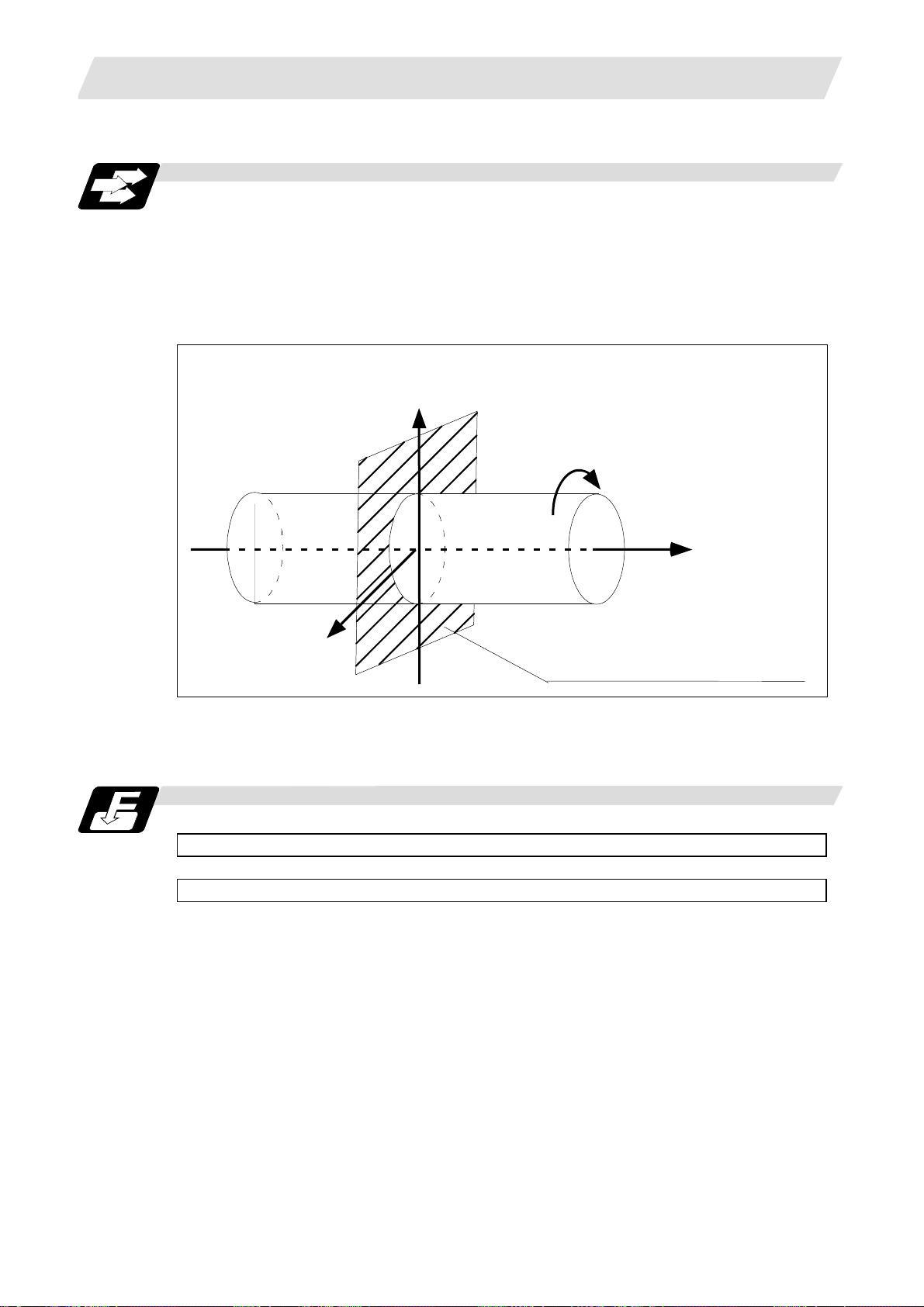
6. Interpolation Functions
6.10 Polar Coordinate Interpolation; G12.1, G13.1
6.10 Polar Coordinate Interpolation; G12.1, G13.1
Function and purpose
This function converts the commands programmed with the orthogonal coordinate axis into linear
axis movement (tool movement) and rotation axis movement (workpiece rotation), and controls the
contour.
The plane that uses the linear axis as the plane's 1st orthogonal axis, and the intersecting
hypothetical axis as the plane's 2nd axis (hereafter "pole coordinate interpolation plane") is
selected. Pole coordinate interpolation is carried out on this plane. The workpiece coordinate
system zero point is used as the coordinate system zero point during pole coordinate interpolation.
Linear axis
X axis
C axis
Z axis
Rotation axis
(hypothetical axis)
Polar coordinate interpolation plane (G17 plane)
This is effective for cutting a notch section on a linear section of the workpiece diameter, and for
cutting cam shafts, etc.
Command format
G12.1 ; Pole coordinate interpolation mode start
G13.1 ; Pole coordinate interpolation mode cancel
(1) The coordinates commanded in the interval from the start to cancellation of the pole
coordinate interpolation mode will be the pole coordinate interpolation.
G12.1 ; Pole coordinate interpolation mode start
: (Pole coordinate interpolation will start)
: (The coordinate commands in this interval will be the pole coordinate
: interpolation)
G13.1 ; Pole coordinate interpolation mode cancel
(Pole coordinate interpolation is canceled)
71
Page 86

6. Interpolation Functions
Detailed description
(1) Command G12.1 and G13.1 in an independent block. A program error (P33) will occur if this
command is issued in the same block as another G code.
(2) Linear interpolation or circular interpolation can be commanded during the pole coordinate
interpolation mode.
(3) The coordinates can be commanded with either an absolute command or incremental
command.
(4) Tool radius compensation can be applied on the program command. Pole coordinate
interpolation will be executed on the path after tool radius compensation.
(5) Command the segment feed in the pole coordinate interpolation plane (orthogonal coordinate
system) with F. The F unit is mm/min or inch/min.
(6) When the G12.1 command is issued, the deceleration check is executed.
(7) Plane selection
The linear axis and rotation axis used for pole coordinate interpolation must be set beforehand
with the parameters.
6.10 Polar Coordinate Interpolation; G12.1, G13.1
(a) Determine the deemed plane for carrying out pole coordinate interpolation with the
parameter (#1533) for the linear axis used for pole coordinate interpolation.
#1533 setting value Deemed plane
X G17 (XY plane)
Y G19 (YZ plane)
Z G18 (ZX plane)
Blank (no setting) G17 (XY plane)
(b) A program error (P485) will occur if the plane selection command (G16 to G19) is issued
during the pole coordinate interpolation mode.
(Note) Depending on the model or version, parameter (#1533) may not be provided. In this case,
the operation will be the same as if the parameter (#1533) is blank (no setting).
72
Page 87

6. Interpolation Functions
(8) F command during pole coordinate interpolation
As for the F command in the pole coordinate interpolation mode, whether the previous F
command is used or not depends on that the mode just before G12.1 is the feed per minute
command (G94/G98) or feed per rotation command (G95/G99).
(a) When G94(G98) is commanded just before G12.1
If there is no F command in the pole coordinate interpolation, the previous F command
feedrate will be used.
The feedrate after the pole coordinate interpolation mode is canceled will remain the F
command feedrate issued when the pole coordinate interpolation mode was started or the
final F command feedrate set during pole coordinate interpolation.
The previous F command feedrate cannot be used during pole coordinate interpolation.
(b) When G95(G99) is commanded just before G12.1
The previous F command feedrate cannot be used during pole coordinate interpolation. A
new F command must be issued.
The feedrate after the pole coordinate interpolation mode is canceled will return to that
applied before the pole coordinate interpolation mode was started.
When there is no F command in G12.1
When F is commanded in G12.1
6.10 Polar Coordinate Interpolation; G12.1, G13.1
Previous mode No F command After G13.1 is canceled
G94(G98) Previous F is used
←
G95(G99) Program error (P62) F just before G12.1 is used
Previous mode No F command After G07.1 is canceled
G94(G98) Commanded F is used
←
G95(G99) Commanded F is used *1 F just before G12.1 is used
*1) Moves with the feed per minute command during G12.1.
(9) Related parameters
# Item Details
1516 mill_ax Milling axis
name
1517 mill_c Milling
interpolation
hypothetical
axis name
8111 Milling Radius Select the diameter and radius of the linear axis for
1533 mill_Pax Polar
coordinate
linear axis
name
Set the name of the rotation axis for milling interpolation
(pole coordinate interpolation, cylindrical interpolation).
Only one of the rotation axes can be set.
Select the hypothetical axis command name for milling
interpolation (pole coordinate interpolation, cylindrical
interpolation).
0: Y axis command
1: Command rotation axis name
milling interpolation.
0: Radius command for all axes
1: Each axis setting (follows #1019 dia diameter
designation axis)
Set the linear axis for polar coordinate interpolation. Axis
Setting
range
A to Z
0 / 1
0 / 1
name
73
Page 88

6. Interpolation Functions
Relation with other functions
(1) The following G code commands can be used during the pole coordinate interpolation mode.
G code Details
G00
G01
G02
G03
G04
G09
G40-42
G61
G64
G65
G66
G66.1
G67
G80-89
G90/91
G94
G98
G99
6.10 Polar Coordinate Interpolation; G12.1, G13.1
Positioning
Linear interpolation
Circular interpolation (CW)
Circular interpolation (CWW)
Dwell
Exact stop check
Tool radius compensation
Exact stop check mode
Cutting mode
Macro call (simple call)
Macro modal call A (modal call)
Macro modal call B (block call per macro)
Macro modal call cancel (modal call cancel)
Hole drilling fixed cycle
Absolute/incremental value command
Asynchronous feed
Hole drilling cycle initial return
Hole drilling cycle R point return
A program error (P481) may occur if a G code other than those listed above is commanded
during pole coordinate interpolation.
(2) Program commands during pole coordinate interpolation
(a) The program commands in the pole coordinate interpolation mode are commanded with
the orthogonal coordinate value of the linear axis and rotation axis (hypothetical axis) on
the pole coordinate interpolation plane.
The axis address of the rotation axis (C) is commanded as the axis address for the plane's
2nd axis (hypothetical axis) command.
The command unit is not degree, and instead is the same unit (mm or inch) as the
command issued with the axis address for the plane's 1st axis (linear axis).
(b) The hypothetical axis coordinate value will be set to "0" when G12.1 is commanded. In
other words, the position where G12.1 is commanded will be interpreted as angle = 0, and
the pole coordinate interpolation will start.
(3) Circular interpolation on pole coordinate plane
The arc radius address for carrying out circular interpolation during the pole coordinate
interpolation mode is determined with the linear axis parameter (#1533).
#1533 setting value Center designation command
X I, J (pole coordinate plane is interpreted as XY plane)
Y J, K (pole coordinate plane is interpreted as YZ plane)
Z K, I (pole coordinate plane is interpreted as ZX plane)
Blank (no setting) I, J (pole coordinate plane is interpreted as XY plane)
The arc radius can also be designated with the R command.
(Note) Depending on the model or version, parameter (#1533) may not be provided. In this case,
the operation will be the same as if the parameter (#1533) is blank (no setting).
74
Page 89

6. Interpolation Functions
(4) Tool radius compensation
The tool radius can be compensated during the pole coordinate interpolation mode.
(a) Command the plane selection in the same manner as pole coordinate interpolation.
When using tool radius compensation, it must be started up and canceled within the pole
coordinate interpolation mode.
(b) A program error (P485) will occur if polar coordinate interpolation is executed during tool
radius compensation.
(c) If the G12.1 and G13.1 commands are issued with no movement command given after the
tool radius compensation is canceled, the position of the axis in the G12.1 and G13.1
commands block is interpreted as the position applied after the tool radius compensation
is canceled and the following operations are performed.
(5) Tool length compensation
(a) A program error (P481) will occur if the tool length compensation is carried out in the polar
coordinate interpolation mode.
:
:
G43 H12 ;
G0 X100. Z0 ;
G12.1 ;
:
G43 H11 ;
:
G13.1 ;
6.10 Polar Coordinate Interpolation; G12.1, G13.1
...Tool length compensation before polar coordinate interpolation → Valid
...Tool length compensation in polar coordinate interpolation mode →
Program error
(b) Complete the tool compensation operation (movement of tool length and wear
compensation amount) before executing the polar coordinate interpolation. If the tool
compensation operation is not completed when the polar coordinate interpolation start
command has been issued, the followings will be resulted:
●Machine coordinate is not changed even if G12.1 is executed..
●The workpiece coordinate is changed to that of the post tool length compensation when
G12.1 is executed. (Even if canceling the polar coordinate interpolation, this workpiece
coordinate will not be canceled.)
(6) Cutting asynchronous feed
(a) The asynchronous mode is forcibly set when the pole coordinate interpolation mode is
started.
(b) When the pole coordinate interpolation mode is canceled, the synchronization mode will
return to the state before the pole coordinate interpolation mode was started.
(c) A program error (P485) will occur if G12.1 is commanded in the constant surface speed
control mode (G96).
(7) Miscellaneous functions
(a) The miscellaneous function (M) and 2nd miscellaneous function can be issued even in the
pole coordinate interpolation mode.
(b) The S command in the pole coordinate interpolation mode issues the rotary tool's rotation
speed instead of the spindle rotation speed.
75
Page 90

6. Interpolation Functions
(8) Hole drilling axis in the hole drilling fixed cycle command during the pole coordinate
interpolation
Hole drilling axis in the hole drilling fixed cycle command during the pole coordinate
interpolation is determined with the linear axis parameter (#1533).
(9) Shift amount in the G76 (fine boring) or G87 (back boring) command during the pole
coordinate interpolation
Shift amount in the G76 (fine boring) or G87 (back boring) command during the pole
coordinate interpolation is determined with the linear axis parameter (#1533).
Restrictions and precautions
(1) The program cannot be restarted (resumed) for a block in pole coordinate interpolation.
6.10 Polar Coordinate Interpolation; G12.1, G13.1
#1533 setting value Hole drilling axis
X Z (pole coordinate plane is interpreted as XY plane)
Y X (pole coordinate plane is interpreted as YZ plane)
Z Y (pole coordinate plane is interpreted as ZX plane)
Blank (no setting) Z (pole coordinate plane is interpreted as XY plane)
#1533 setting value Center designation command
X I, J (pole coordinate plane is interpreted as XY plane)
Y J, K (pole coordinate plane is interpreted as YZ plane)
Z K, I (pole coordinate plane is interpreted as ZX plane)
Blank (no setting) I, J (pole coordinate plane is interpreted as XY plane)
(2) Before commanding pole coordinate interpolation, set the workpiece coordinate system so
that the center of the rotation axis is at the coordinate system zero point. Do not change the
coordinate system during the pole coordinate interpolation mode. (G50, G52, G53, relative
coordinate reset, G54 to G59, etc.)
(3) The feedrate during pole coordinate interpolation will be the interpolation speed on the pole
coordinate interpolation plane (orthogonal coordinate system).
(The relative speed with the tool will be converted with pole coordinate conversion.)
When passing near the center of the rotation axis on the pole coordinate interpolation plane
(orthogonal coordinate system), the rotation axis side feedrate after pole coordinate
interpolation will be very high.
(4) The axis movement command outside of the plane during pole coordinate interpolation will
move unrelated to the pole coordinate interpolation.
(5) The current position displays during pole coordinate interpolation will all indicate the actual
coordinate value. However, the "remaining movement amount" will be the movement amount
on the pole coordinate input plane.
(6) The pole coordinate interpolation mode will be canceled when the power is turned ON or reset.
(7) A program error (P484) will occur if any axis commanded for pole coordinate interpolation has
not completed zero point return.
(8) Tool radius compensation must be canceled before the pole coordinate interpolation mode
can be canceled.
(9) When the pole coordinate interpolation mode is canceled, the mode will change to the cutting
mode, and the plane will return to that selected before pole coordinate interpolation.
(10) A program error (P486) will occur if the pole coordinate interpolation command is issued
during the mirror image.
76
Page 91

6. Interpolation Functions
(11) A program error (P486) will occur if the cylindrical interpolation or the pole coordinate
interpolation is commanded during the pole coordinate interpolation mode.
(12) During pole coordinate interpolation, if X axis moveable range is controlled in the plus side, X
axis has to be moved to the plus area that includes "0" and above before issuing the polar
coordinate interpolation command. If X axis moveable range is controlled in the minus side, X
axis has to be moved to the area that does not include "0" before issuing the polar coordinate
interpolation command.
Example of program
6.10 Polar Coordinate Interpolation; G12.1, G13.1
Hypothetical C axis
<Program>
N07
Hypothetical C axis
N06
N05
C axis
N09 N08
C axis
Tool
N04
N03
N10
Path after tool radius compensation
Program path
N01
N02
N11
X axis
X axis
Z axis
:
N01 G17 G90 G0 X40.0 C0 Z0;
N02 G12.1;
N03 G1 G42 X20.0 F2000;
N04 C10.0;
N05 G3 X10.0 C20.0 R10.0;
N06 G1 X-20.0;
N07 C-10.0;
N08 G3 X-10.0 C-20.0 I10.0 J0;
N09 G1 X20.0;
N10 C0;
N11 G40 X40.0;
N12 G13.1;
Setting of start position
Polar coordinate interpolation mode: Start
Actual machining start
Shape program
(Command the position with the orthogonal
coordinate on X-C hypothetical axis plane.)
Polar coordinate interpolation mode: Cancel
:
:
M30 ;
77
Page 92

6. Interpolation Functions
6.11 Exponential Function Interpolation; G02.3, G03.3
6.11 Exponential Function Interpolation; G02.3, G03.3
Function and purpose
Exponential function interpolation changes the rotation axis into an exponential function shape in
respect to the linear axis movement.
At this time, the other axes carry out linear interpolation between the linear axis.
This allows a machining of a taper groove with constant torsion angle (helix angle) (uniform helix
machining of taper shape).
This function can be used for slotting or grinding a tool for use in an end mill, etc.
• Uniform helix machining of taper shape
Z axis
A axis
(Rotation axis)
(G01)
J1
Torsion angle: J1=J2=J3
(G00)
(G02.3/G03.3)
J2
J3
(G01)
X axis
(Linear axis)
• Relation of linear axis and rotation axis
"Relation of linear axis and rotation axis"
X axis
(Linear axis)
CA
X=B (e
{B, C ... constant}
-1)
78
A axis
(Rotation axis)
Page 93

6. Interpolation Functions
Command format
G02.3/G03.3 Xx1 Yy1 Zz1 Ii1 Jj1 Rr1 Ff1 Qq1 Kk1 ;
G02.3 : Forward rotation interpolation (modal)
G03.3 : Negative rotation interpolation (modal)
X
Y
Z
I
J
R
F
Q
K : Command will be ignored.
(Note 1) Designate the end point of the linear axis designated with parameter "#1514 expLinax" and
the axis that carries out linear interpolation between that axis.
If the end point on of the rotation axis designated with parameter "#1515 expRotax" is
designated, linear interpolation without exponential function interpolation will take place.
(Note 2) The command unit is as follows.
6.11 Exponential Function Interpolation; G02.3, G03.3
: X axis end point (Note 1)
: Y axis end point (Note 1)
: Z axis end point (Note 1)
: Angle i1 (Note 2)
: Angle j1 (Note 2)
: Constant value r1 (Note 3)
: Initial feedrate (Note 4)
: Feedrate at end point (Note 5)
Setting unit #1003 = B #1003 = C #1003 = D #1003 = E
(Unit = °) 0.001 0.0001 0.00001 0.000001
The command range is -89 to +89°.
A program error (P33) will occur if there is no address I or J command.
A program error (P35) will occur if the address I or J command value is 0.
(Note 3) The command unit is as follows.
Setting unit #1003 = B #1003 = C #1003 = D #1003 = E Unit
Metric system 0.001 0.0001 0.00001 0.000001 mm
Inch system 0.0001 0.00001 0.000001 0.0000001 inch
The command range is a positive value that does not include 0.
A program error (P33) will occur if there is no address R command.
A program error (P35) will occur if the address R command value is 0.
(Note 4) The command unit and command range is the same as the normal F code. (Command
as a per minute feed.)
Command the composite feedrate that includes the rotation axis.
The normal F modal value will not change by the address F command.
A program error (P33) will occur if there is no address F command.
A program error (P35) will occur if the address F command value is 0.
79
Page 94

6. Interpolation Functions
j
A
(Note 5) The command unit is as follows.
Setting unit #1003 = B #1003 = C #1003 = D #1003 = E Unit
Metric system 0.001 0.0001 0.00001 0.000001 mm
Inch system 0.0001 0.00001 0.000001 0.0000001 inch
The command unit and command range is the same as the normal F code.
Command the composite feedrate that includes the rotation axis.
The normal F modal value will not change by the address Q command.
The axis will interpolate between the initial speed (F) and end speed (Q) in the CNC
according to the linear axis.
If there is no address Q command, interpolation will take place with the same value as
the initial feedrate (address F command). (The start point and end point feedrates will be
the same.)
A program error (P35) will occur if the address Q command value is 0.
• Example of uniform helix machining of taper shape
6.11 Exponential Function Interpolation; G02.3, G03.3
Z axis Z axis
i1
r1
1
Linear axis ... X axis, rotation axis ... A axis, linear axis (X axis) start point ... x0
axis
X axis
x1 x0
Relational expression of exponential function
The exponential function relational expression of the linear axis (X) and rotation axis (A) in the
G02.3/G03.3 command is defined in the following manner.
X (θ) = r1 ∗ (e
A (θ) = (-1)
/D
θ
- 1) / tan (i1) (linear axis (X) movement (1))
ω
∗ 360 ∗ θ / (2π) (rotation axis (A) movement)
D = tan (j1) / tan (i1)
ω = 0 during forward rotation (G02.3), and ω = 1 during reverse rotation (G03.3)
θ is the rotation angle (radian) from the rotation axis' start point
The rotation axis' rotation angle (θ) is as follows according to expression (1).
θ = D ∗ 1n { (X ∗ tan (i1) / r1) + 1 }
80
Page 95

6. Interpolation Functions
j
A
Machining example
• Example of uniform helix machining of taper shape
Z axis
z1
z2
z0
6.11 Exponential Function Interpolation; G02.3, G03.3
i1
p1
axis
X axis
x0 x2
r1 r2
1
x1
<Relational expression of exponential function in machining example>
/D
Z (θ) = r1 ∗ (e
X (θ) = r1 ∗ (e
A (θ) = (-1)
θ
-1) ∗ tan (p1) / tan (i1) + z0 ... (1)
/D
θ
-1) / tan (i1) ... (2)
ω
∗ 360 ∗ θ / (2π)
D = tan (j1) / tan (i1)
Z (θ) Absolute value from zero point of Z axis (axis that linearly interpolates between interval
with linear axis (X axis))
X (θ) Absolute value from X axis (linear axis) start point
A (θ) Absolute value from A axis (rotation axis) start point
r1 Exponential function interpolation constant value (address R command)
r2 Workpiece left edge radius
x2 X axis (linear axis) position at workpiece left edge
x1 X axis (linear axis) end point (address X command)
x0 X axis (linear axis) start point (Set as "x0 ≤ x1" so that workpiece does not interfere with
tool)
z1 End point of Z axis (axis that linearly interpolates between interval with linear axis (X
axis)) (address Z command)
z0 Start point of Z axis (axis that linearly interpolates between interval with linear axis (X
axis))
i1 Taper gradient angle (address I command)
p1 Slot base gradient angle
j1 Torsion angle (helix angle) (address J command)
ω Torsion direction (0: Forward rotation, 1: reverse direction)
θ Workpiece rotation angle (radian)
f1 Initial feedrate (address F command)
q1 Feedrate at end point (address Q command)
k1 Insignificant data (address K command)
According to expressions (1) and (2):
Z (θ) = X (θ) ∗ tan (p1) + z0 ... (3)
According to expression (3), the slot base gradient angle (p1) is determined from the X axis and Z
axis end point positions (x1, z1).
The Z axis movement amount is determined by the slot base gradient angle (p1) and X axis
position.
In the above diagram, the exponential function interpolation's constant value (r1) is determined with
the following expression using the workpiece left edge radius (r2), X axis start point (x0), X axis
position at workpiece left edge (x2) and taper gradient angle (i1).
r1 = r2 - { (x2 - x0) ∗ tan (i1) } ... (4)
81
Page 96

6. Interpolation Functions
The taper gradient angle (i1) and torsion angle (j1) are each issued with the command address I
and J.
Note that if the shape is a reverse taper shape, the taper gradient angle (i1) is issued as a negative
value.
The torsion direction (ω) is changed with the G code. (Forward rotation when G02.3 is commanded,
negative rotation when G03.3 is commanded)
The above settings allow uniform helix machining of a taper shape (or reverse taper shape).
Command and operation
Z
Start
point
Command
r1
6.11 Exponential Function Interpolation; G02.3, G03.3
G2.3(Equivalent to G3.3 if j1<0)
X movement direction > 0 X movement direction < 0
i1>0 i1<0 i1>0 i1<0
+
+
i1
-
j1
End
point
r1
End
point
X
i1
j1
Z
Start
point
r1
End
point
X
i1
r1
End
point
Z
Start
point
X
i1
j1
Z
-
Start
point
j1
X
A
Operation
N10 G28XYZC;
N20 G91G0 X100. Z100.;
N30 G2.3 X100. Z100.
I50. J80. R105. F500.;
Machining
N40 M30;
program example
i1>0 i1<0 i1>0 i1<0
Z
Start
point
r1
Command
A
A
X
N10 G28XYZC;
N20 G91G0 X100. Z200.;
N30 G2.3 X100. Z-100.
I-50. J80. R105. F500.;
N40 M30;
X
N10 G28XYZC;
N20 G91G0 X-100. Z100.;
N30 G2.3 X-100. Z100.
I50. J80. R105. F500.;
N40 M30;
A
X
N10 G28XYZC;
N20 G91G0 X-100. Z200.;
N30 G2.3 X-100. Z-100.
I-50. J80. R105. F500.;
N40 M30;
G3.3(Equivalent to G2.3 if j1<0)
X movement direction > 0 X movement direction < 0
+
-
j1
End
point
r1
End
point
X
i1
j1
Z
Start
point
r1
X
End
point
r1
i1
j1
X
A
X
point
End
Z
Start
point
X
i1
j1
A
X
A
X
+
Z
-
Start
point
X
A
X
Operation
N10 G28XYZC;
N20 G91G0 X100. Z100.;
N30 G3.3 X100. Z100.
I50. J80. R105. F500.;
Machining
N40 M30;
program example
N10 G28XYZC;
N20 G91G0 X100. Z200.;
N30 G3.3 X100. Z-100.
I-50. J80. R105. F500.;
N40 M30;
82
N10 G28XYZC;
N20 G91G0 X-100. Z100.;
N30 G3.3 X-100. Z100.
I50. J80. R105. F500.;
N40 M30;
N10 G28XYZC;
N20 G91G0 X-100. Z200.;
N30 G3.3 X-100. Z-100.
I-50. J80. R105. F500.;
N40 M30;
Page 97

6. Interpolation Functions
Precautions for programming
(1) When G02.3/G03.3 is commanded, interpolation takes place with the exponential function
relational expression using the start position of the linear axis and rotation axis as 0.
(2) Linear interpolation will take place in the following cases, even if in the G02.3/G03.3 mode.
The feedrate for linear interpolation will be the F command in that block. (Note that the normal
F modal is not updated.)
• The linear axis designated with the parameter (#1514 expLinax) is not commanded, or the
movement amount for that axis is 0.
• The rotation axis designated with the parameter (#1515 expRotax) is commanded.
(3) A program error will occur if the following commands are issued in G02.3 or G03.3 mode. A
program error will also occur if G02.3 or G03.3 command is issued in the following modes.:
• Tool length compensation
(A program error will occur only when the compensation starts at the same time as the
movement by exponential function interpolation. The tool length compensation will operate
normally if it has started before the G02.3/G03.3 mode starts.
• Tool radius compensation
• High-speed high-accuracy control
• High-speed machining
• Scaling
• Tool length compensation along tool axis
• Figure rotation
• Coordinate rotation by program
• Coordinate rotation by parameter
• 3-dimentional coordinate conversion
6.11 Exponential Function Interpolation; G02.3, G03.3
(4) A program error (P481) will occur if commands are issued during the pole coordinate
interpolation, cylindrical interpolation or milling interpolation modes.
(5) Program error (P612) will occur if commands are issued during the scaling or mirror image.
(6) Program error (P34) will occur if commands are issued during the high-speed high-accuracy
control II.
(7) G02.3/G03.3 will function with asynchronous feed even during the synchronous feed mode.
(8) If the parameter "#1515 expRota" setting is the same axis name as the initial C axis, the axis
selected with the C axis selection signal will interpolate as the rotation axis.
83
Page 98

6. Interpolation Functions
6.12 Polar Coordinate Command; G16/G15
Function and purpose
With this function, the end point coordinate value is commanded with the polar coordinate of the
radius and angle.
Command format
G16 ; Polar coordinate command mode ON
G15 ; Polar coordinate command mode OFF
Detailed description
(1) The polar coordinate command is applied in the interval from turning ON to OFF of the polar
coordinate command mode.
G1x ;
G16 ;
Plane selection for polar coordinate command (G17/G18/G19)
Polar coordinate command mode ON
G9x G01 Xx1 Yy1 F2000 ;: Polar coordinate command
G9x : Center selection for polar coordinate command (G90/G91)
G90
G91
x1 : 1st axis for the plane
y1 : 2nd axis for the plane
Y
6.12 Polar Coordinate Command; G16/G15
• • •The workpiece coordinate system zero point is the
polar coordinate center.
• • •The present position is the polar coordinate center.
• • •The radius commanded
• • •The angle commanded
Commanded position
x1
Plus
y1
Minus
Present position
X
G15 ;
For G90/G17(X-Y plane)
Polar coordinate command mode OFF
(2) The plane selection during the polar coordinate command mode is carried out with G17, G18
and G19.
(3) The polar coordinate command is a modal. The polar coordinate command mode when the
power is turned ON is OFF (G15). Whether to initialize the modal at reset or not can be
selected with the parameter (#1210 RstGmd/bit 11) setting.
(4) During polar coordinate command mode, command the radius with the 1st axis for the
selected plane, and the angle with the 2nd axis. For example, when the X-Y plane is selected,
command the radius with the address "X", and the angle with the address "Y".
(5) For the angle, the counterclockwise direction of the selected plane is positive and the
clockwise direction is negative.
(6) The radius and angle can be commanded with both the absolute value and incremental value
(G90, G91).
84
Page 99

6. Interpolation Functions
(7) When the radius is commanded with the absolute value, command the distance from the zero
point in the workpiece coordinate system (note that the local coordinate system is applied
when the local coordinate system is set).
(8) When the radius is commanded with the incremental value command, considering the end
point of the previous block as the polar coordinate center, command the incremental value
from that end point. The angle is commanded with the incremental value of the angle from the
previous block.
(9) When the radius is commanded with the negative value, the same operation as the command
that the radius command value is changed to the absolute value and 180° is added to the
angle command value.
Command position
(1) When the zero point in the workpiece coordinate system is applied to the polar
coordinate center
The zero point in the workpiece coordinate system is applied to the polar coordinate center by
commanding the radius with the absolute value. Note that the zero point in the local coordinate
system is applied to the polar coordinate center if the local coordinate system (G52) is used.
6.12 Polar Coordinate Command; G16/G15
Command position
Radius
Radius
Angle
When the angle is the absolute
value command
Command position when the zero point in the workpiece coordinate system is applied to
the polar coordinate center
(2) When the present position is applied to the polar coordinate center
The present position is applied to the polar coordinate center by commanding the radius with
the incremental value.
Command position
Radius
Present
position
When the angle is the incremental
value command
Radius
Angle
Command position
Angle
Command position
Present
position
Angle
Present
position
When the angle is the absolute
value command
Command position when the present position is applied to the polar coordinate center
85
When the angle is the incremental
value command
Present
position
Page 100

6. Interpolation Functions
Ang
(3) When the radius command is omitted
When the radius command is omitted, the zero point in the workpiece coordinate system is
applied to the polar coordinate center, and the distance between the polar coordinate center
and current position is regarded as the radius.
Note that the zero point in the local coordinate system is applied to the polar coordinate center
if the local coordinate system (G52) is used.
6.12 Polar Coordinate Command; G16/G15
Command position
Angle
When the angle is the absolute
value command
Command position when the radius command is omitted
(4) When the angle command is omitted
When the angle command is omitted, the angle of the present position in the workpiece
coordinate system is applied to the angle command.
The zero point in the workpiece coordinate system is applied to the polar coordinate center by
commanding the radius with the absolute value. Note that the zero point in the local coordinate
system is applied to the polar coordinate center if the local coordinate system (G52) is used.
If the radius is commanded with the incremental value, the present position is applied to the
polar coordinate center.
Present
position
Radius
When the angle is the incremental
value command
Command position
Command position
Angle
Radius
Command position
Present
position
le
Angle
Present position
Radius
When the radius is the absolute
value command
Command position when the angle command is omitted
86
When the radius is the incremental
value command
Present position
Radius
 Loading...