

MITSUBISHI CNC 700 Training Manual


Introduction of <CNC 700 Series Maintenance Training> Course
Course name : CNC 700 Series maintenance
Maximum number
of trainees
Aim of the course : to learn about maintenance of CNC 700 Series
Intended trainees : Engineers in charge of NC machine tool maintenance
Textbook to use : 700 Series Maintenance Training Manual
NC model to use : CNC 700 Series
Curriculum (One-day course)
Date Time Contents
Day ( ) Month ( )
9:15
to
12:00
13:00
to
: 5
Orientation
NC system hardware configuration
Maintenance and diagnosis screens
Data input/output operation and practice
NC alarms and part replacement practice
NC setup and practice
Drive system maintenance and part
The entry of
participation
record
16:30
replacement practice
Drive system alarms and their remedies


Preface
This textbook is designed to be used in "CNC 700 Series maintenance training course".
Operations and procedures described in this textbook are basically standard ones. Therefore, they may
be different from yours, depending on your NC model, machine tool builder, machine type, and so on.
Before you carry out actual maintenance such as part replacement, we recommend you to consult with
our service center.
As this textbook has been written based mostly on the following manuals, please refer to them for the
details.
• 700/70 Series Instruction Manual.................................................................. IB-1500042(ENG)
• 700/70 Series Setup Manual ......................................................................... IB-1500124(ENG)
• 700 Series Connection Manual ..................................................................... IB-1500034(ENG)
• MDS-D/DH Series Instruction Manual........................................................... IB-1500025(ENG)
• MDS-D-SVJ3/SPJ3 Series Instruction Manual.............................................. IB-1500193(ENG)


Contents
1. 700 Series System Configuration .......................................................................................................................1
1.1 NC Configuration...........................................................................................................................................1
1.2 System Configuration....................................................................................................................................2
1.2.1 System Basic Configuration Drawing .....................................................................................................2
1.2.2 General Connection Diagram .................................................................................................................3
1.2.2.1 Display Unit: FCU7-DA201-11/FCU7-DA211-11..............................................................................3
1.2.2.2 Display Unit:
FCU7-DA315-11/FCU7-DA415-11/FCU7-DA445-11/FCU7-DA335-11/FCU7-DA435-11............................4
1.2.3 List of Configuration Units ......................................................................................................................5
1.2.3.1 Control Unit: FCU7-MU001/FCU7-MU002/FCU7-MU011/FCU7-MA011 ........................................5
1.2.3.2 Display Unit:
FCU7-DA201/FCU7-DA211/FCU7-DA315/FCU7-DA415/FCU7-DA445/FCU7-DA335/FCU7-DA435 .......6
1.2.3.3 Operation Panel I/O Unit: FCU7-DX670/FCU7-DX671/FCU7-DX770/FCU7-DX771...................... 7
1.2.3.4 Keyboard Unit : FCU7-KB021/FCU7-KB022/FCU7-KB041.............................................................7
1.2.3.5 Remote I/O Unit: FCUA-DX100/DX110/DX120/DX140/DX101/DX111/DX121/DX141 ...................8
1.2.3.6 Scan I/O: HR357/HR347..................................................................................................................8
1.2.3.7 Card-sized I/O Card: HR361/HR371/HR381/HR383.......................................................................8
1.2.3.8 Extended I/O Card: QY231..............................................................................................................9
1.2.3.9 Front IC Card Interface: FCU7-EP102-1 (option) ............................................................................9
1.2.3.10 Hard Disk Unit: FCU7-HD001-1.....................................................................................................9
1.2.3.11 Floppy Disk Unit: FCU7-FD221......................................................................................................9
1.2.3.12 Expansion Unit: FCU7-EX891 .....................................................................................................10
1.2.3.13 Expansion Card............................................................................................................................10
1.2.3.14 External Power Supply Unit: PD25/PD27 ....................................................................................10
2. Maintenance Screens .......................................................................................................................................11
2.1 Input/Output Screen ....................................................................................................................................11
2.1.1 Changing the Valid Area.......................................................................................................................14
2.1.2 Selecting a Device, Directory and File..................................................................................................15
2.1.3 Transferring a File.................................................................................................................................22
2.1.4 Comparing Files (Compare) .................................................................................................................24
2.1.5 Formatting an External Device .............................................................................................................25
2.1.6 List of File Names.................................................................................................................................25
2.2 All Backup Screen .......................................................................................................................................26
2.2.1 Performing a Backup Operation ...........................................................................................................28
2.2.2 Performing a Restore Operation...........................................................................................................28
2.2.3 Setting Automatic Backup.....................................................................................................................29
2.2.4 Backing up the SRAM ..........................................................................................................................30
2.3 Absolute Position Setting Screen................................................................................................................32
2.3.1 Selecting the Axis .................................................................................................................................34
2.3.2 Carrying Out Dogless-type Zero Point Initialization..............................................................................35
2.3.3 Carrying Out Dog-type Zero Point Initialization ....................................................................................43
2.3.4 Precautions...........................................................................................................................................43
2.4 Auxiliary Axis Test Screen ...........................................................................................................................46
2.4.1 Preparation ...........................................................................................................................................49
2.4.2 Selecting a Device, Directory and File..................................................................................................50
2.4.3 Test Operation ......................................................................................................................................54
2.4.4 Precaution.............................................................................................................................................54
3. Diagnosis Screens ............................................................................................................................................55
3.1 System Configuration Screen .....................................................................................................................55
3.2 Option Display Screen.................................................................................................................................58
3.3 I/F Diagnosis Screen ...................................................................................................................................59
3.3.1 Displaying the PLC Device Data ..........................................................................................................62
3.3.2 Carrying Out Modal Output...................................................................................................................63
3.3.3 Carrying Out One-shot Output..............................................................................................................64
3.4 Drive Monitor Screen...................................................................................................................................65
3.4.1 Servo Axis Unit Display Items...............................................................................................................67
3.4.2 Spindle Unit Display Items....................................................................................................................70
3.4.3 Display Items for the Power Supply Unit ..............................................................................................79

3.4.4 Display Items for the Auxiliary Axis Unit ...............................................................................................81
3.4.5 Display Items for the Synchronous Error..............................................................................................83
3.4.6 Clearing the Alarm History ....................................................................................................................84
3.5 NC Memory Diagnosis Screen (NC Memory Diagn Screen) ......................................................................85
3.5.1 Writing/Reading the Data Using the NC Data Designation ..................................................................87
3.6 Alarm Screen ...............................................................................................................................................88
3.6.1 Alarm History ........................................................................................................................................90
3.7 Self Diagnosis Screen.................................................................................................................................92
4. NC's Maintenance Check and Replacement Procedure ..................................................................................96
4.1 Maintenance Items......................................................................................................................................96
4.1.1 Escutcheon ...........................................................................................................................................96
4.1.2 LCD Panel ............................................................................................................................................97
4.1.3 Compact Flash/IC card.........................................................................................................................97
4.2 H/W Replacement Methods ........................................................................................................................98
4.2.1 Durable Parts........................................................................................................................................98
4.2.1.1 Control unit battery.........................................................................................................................98
4.2.1.2 Cooling fan for control unit...........................................................................................................100
4.2.1.3 Cooling fan for display unit (XP terminal) ....................................................................................101
4.2.1.4 Backlight.......................................................................................................................................102
4.2.2 Unit .....................................................................................................................................................105
4.2.2.1 Control Unit ..................................................................................................................................105
4.2.2.2 Display Unit..................................................................................................................................107
4.2.2.3 Keyboard unit...............................................................................................................................108
4.2.2.4 DX Unit.........................................................................................................................................110
4.2.2.5 Hard Disk Unit.............................................................................................................................. 111
4.2.3 Compact Flash.................................................................................................................................... 112
4.2.3.1 Control Unit Compact Flash.........................................................................................................112
4.2.4 IC card ................................................................................................................................................113
4.2.4.1 Front IC Card ...............................................................................................................................113
5. NC Setup Procedures..................................................................................................................................... 114
5.1 Setup Procedure after SRAM Clear .......................................................................................................... 114
5.1.1 Outline of Hardware Configuration .....................................................................................................114
5.1.2 Outline of Setup Procedures ..............................................................................................................115
5.1.2.1 When there is no all backup data.................................................................................................115
5.1.2.2 When there is all-backup data .....................................................................................................116
5.2 Setup Details ............................................................................................................................................. 117
5.2.1 Erasing the backed up data (SRAM)..................................................................................................117
5.2.2 Inputting the Parameters ....................................................................................................................118
5.2.2.1 When There is No Parameter File ...............................................................................................118
5.2.2.2 When a Parameter File is Available ............................................................................................. 119
5.2.2.3 Parameter Screens ......................................................................................................................120
5.2.3 Formatting the File System.................................................................................................................131
5.2.4 Integrated Time Display......................................................................................................................132
5.2.4.1 Setting the Integrated Time..........................................................................................................133
5.2.4.2 Setting the Time Display Selection ..............................................................................................134
5.2.5 Credit System .....................................................................................................................................135
5.2.6 Absolute Position Detection System...................................................................................................137
5.2.6.1 Dog-type Reference Position Return Operation ..........................................................................137
5.2.6.2 Starting up the Absolute Position Detection System....................................................................138
5.2.7 Auxiliary Axis Operation......................................................................................................................140
5.2.7.1 Preparations.................................................................................................................................140
5.2.7.2 Absolute Position Initial Setting....................................................................................................141
5.2.7.3 Test Operation..............................................................................................................................141
5.2.7.4 PLC device...................................................................................................................................142
5.2.7.5 Notes............................................................................................................................................145
5.2.8 PLC Switch Function ..........................................................................................................................146
5.2.8.1 Turning PLC Switches ON/OFF...................................................................................................147
5.3 7-segment LED's Alarm/Status Indication .................................................................................................148
5.3.1 Outline ................................................................................................................................................148
5.3.2 Status Display.....................................................................................................................................148
5.3.3 Alarm Display ......................................................................................................................................148

5.3.4 Notes ..................................................................................................................................................149
5.3.5 Example of alarm display ...................................................................................................................150
6. Drive Unit Maintenance...................................................................................................................................158
6.1 MDS-D/DH Series .....................................................................................................................................158
6.1.1 Part system connection diagram ........................................................................................................158
6.1.2 Maintenance .......................................................................................................................................159
6.1.2.1 Inspections ...................................................................................................................................159
6.1.2.2 Service parts ................................................................................................................................159
6.1.2.3 Adding and replacing units and parts...........................................................................................160
6.1.2.3.1 Replacing the drive unit.........................................................................................................160
6.1.2.3.2 Replacing the unit fan............................................................................................................161
6.1.2.3.3 Replacing the battery ............................................................................................................162
6.1.2.3.4 Replacing the fuse.................................................................................................................164
6.2 MDS-D-SVJ3/SPJ3 Series........................................................................................................................165
6.2.1 Part system connection diagram ........................................................................................................165
6.2.2 Maintenance .......................................................................................................................................166
6.2.2.1 Inspections ...................................................................................................................................166
6.2.2.2 Service parts ................................................................................................................................166
6.2.2.3 Adding and replacing units and parts...........................................................................................167
6.2.2.3.1 Replacing the drive unit.........................................................................................................167
6.2.2.3.2 Replacing the unit fan............................................................................................................168
6.2.2.3.3 Replacing the battery ............................................................................................................169
7. Servo System Maintenance............................................................................................................................170
7.1 D/A output specifications for servo drive unit ............................................................................................170
7.1.1 MDS-D/DH Series...............................................................................................................................170
7.1.1.1 D/A output specifications..............................................................................................................170
7.1.1.2 Setting the output data.................................................................................................................171
7.1.1.3 Setting the output magnification...................................................................................................172
7.1.2 MDS-D-SVJ3 Series...........................................................................................................................173
7.1.2.1 D/A output specifications..............................................................................................................173
7.1.2.2 Setting the output data.................................................................................................................174
7.1.2.3 Setting the output magnification...................................................................................................175
7.2 Vibration Suppression ...............................................................................................................................176
7.2.1 Notch filte............................................................................................................................................176
8. Spindle System Maintenance .........................................................................................................................177
8.1 D/A output specifications for spindle drive unit .........................................................................................177
8.1.1 MDS-D/DH Series...............................................................................................................................177
8.1.1.1 D/A output specifications..............................................................................................................177
8.1.1.2 Setting the output data.................................................................................................................178
8.1.1.3 Setting the output magnification...................................................................................................180
8.1.2 MDS-SPJ3 Series...............................................................................................................................181
8.1.2.1 D/A output specifications..............................................................................................................181
8.1.2.2 Setting the output data.................................................................................................................182
8.1.2.3 Setting the output magnification...................................................................................................184
8.2 Diagnostic Procedure When Vibration/Noise Occurs ...............................................................................185
8.2.1 How to judge whether the cause is on machine side or control unit side...........................................185
8.2.2 How to judge PLG trouble ..................................................................................................................185
8.2.3 How to check PLG waveform .............................................................................................................186
8.2.3.1 Configuration of serial detector TS5691 ......................................................................................186
8.2.3.2 Adjust A and B phase signals.......................................................................................................187
8.2.3.3 Check Z phase signal ..................................................................................................................188
8.3 Adjustment of Orientation Stop Position....................................................................................................190
9. Servo/Spindle's Troubleshooting.....................................................................................................................191
9.1 MDS-D/DH Series .....................................................................................................................................191
9.1.1 Points of caution and confirmation .....................................................................................................191
9.1.1.1 LED display when alarm or warning occurs.................................................................................192
9.1.2 Protective functions list of units ..........................................................................................................193
9.1.2.1 List of alarms................................................................................................................................193
9.1.2.2 List of warnings ............................................................................................................................197
9.1.3 Troubleshooting ..................................................................................................................................200
9.1.3.1 Troubleshooting at power ON ......................................................................................................200

9.1.3.2 Troubleshooting for each alarm No..............................................................................................201
9.1.3.3 Troubleshooting for each warning No..........................................................................................224
9.1.3.4 Parameter numbers during initial parameter error.......................................................................226
9.1.3.5 Troubleshooting the spindle system when there is no alarm or warning.....................................227
9.2 MDS-D-SVJ3/SPJ3 Series........................................................................................................................229
9.2.1 Points of caution and confirmation .....................................................................................................229
9.2.1.1 LED display when alarm or warning occurs.................................................................................230
9.2.2 Protective functions list of units ..........................................................................................................231
9.2.2.1 List of alarms................................................................................................................................231
9.2.2.2 List of warnings ............................................................................................................................234
9.2.3 Troubleshooting ..................................................................................................................................237
9.2.3.1 Troubleshooting at power ON ......................................................................................................237
9.2.3.2 Troubleshooting for each alarm No..............................................................................................238
9.2.3.3 Troubleshooting for each warning No..........................................................................................256
9.2.3.4 Parameter numbers during initial parameter error.......................................................................258
9.2.3.5 Troubleshooting the spindle system when there is no alarm or warning.....................................259
10. Appendix .......................................................................................................................................................261
10.1 List of Alarms...........................................................................................................................................261
10.1.1 Operation Alarms..............................................................................................................................261
10.1.2 Stop Codes .......................................................................................................................................269
10.1.3 Servo/Spindle Alarms .......................................................................................................................273
10.1.4 MCP Alarm........................................................................................................................................282
10.1.5 System Alarms..................................................................................................................................292
10.1.6 Absolute Position Detection System Alarms.....................................................................................298
10.1.7 Distance-coded Reference Scale Errors..........................................................................................301
10.1.8 Messages during Emergency Stop...................................................................................................302
10.1.9 Auxiliary Axis Alarms.........................................................................................................................304
10.1.10 Computer Link Errors .....................................................................................................................311
10.1.11 User PLC Alarms ............................................................................................................................312
10.1.12 Network Service Errors...................................................................................................................314
10.2 RS-232C I/O Device Parameter Setting Examples.................................................................................315
1. 700 Series System Configuration
1. 700 Series System Configuration
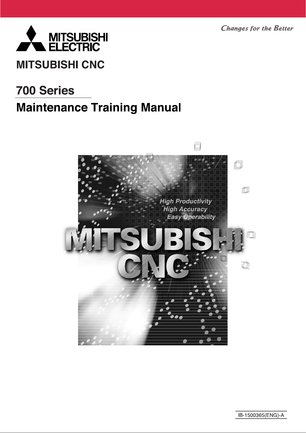
1.1 NC Configuration
1.1 NC Configuration
WindowsXPe
WWiinnddoowwssCCEE..nneett
10.4-type
TFT
10.4-type
TFT
Any combination is possible
M750 for 5-axis machine
Number of simultaneous contour
control axes: 8 axes
5-axis machining related functions
Nano command
High-speed high-accuracy/SSS
control
M730 for high-end machine
Nano command
High-speed high-accuracy/SSS
control
M: Max. 2 part systems
L: Max. 4 part systems
M720 for general-use machine
0.1μ command
M: Max. 1 part system
8.4-type
TFT
L: Max. 2 part systems
1
1. 700 Series System Configuration
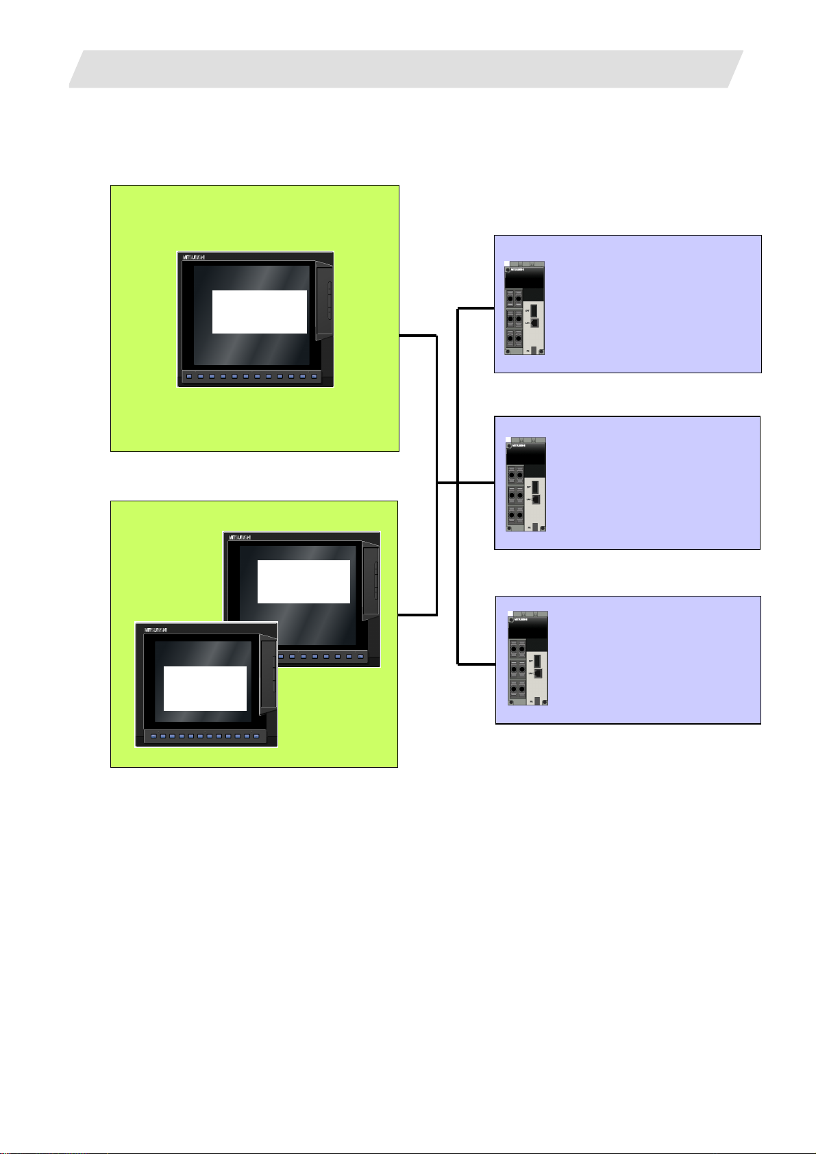
1.2 System Configuration
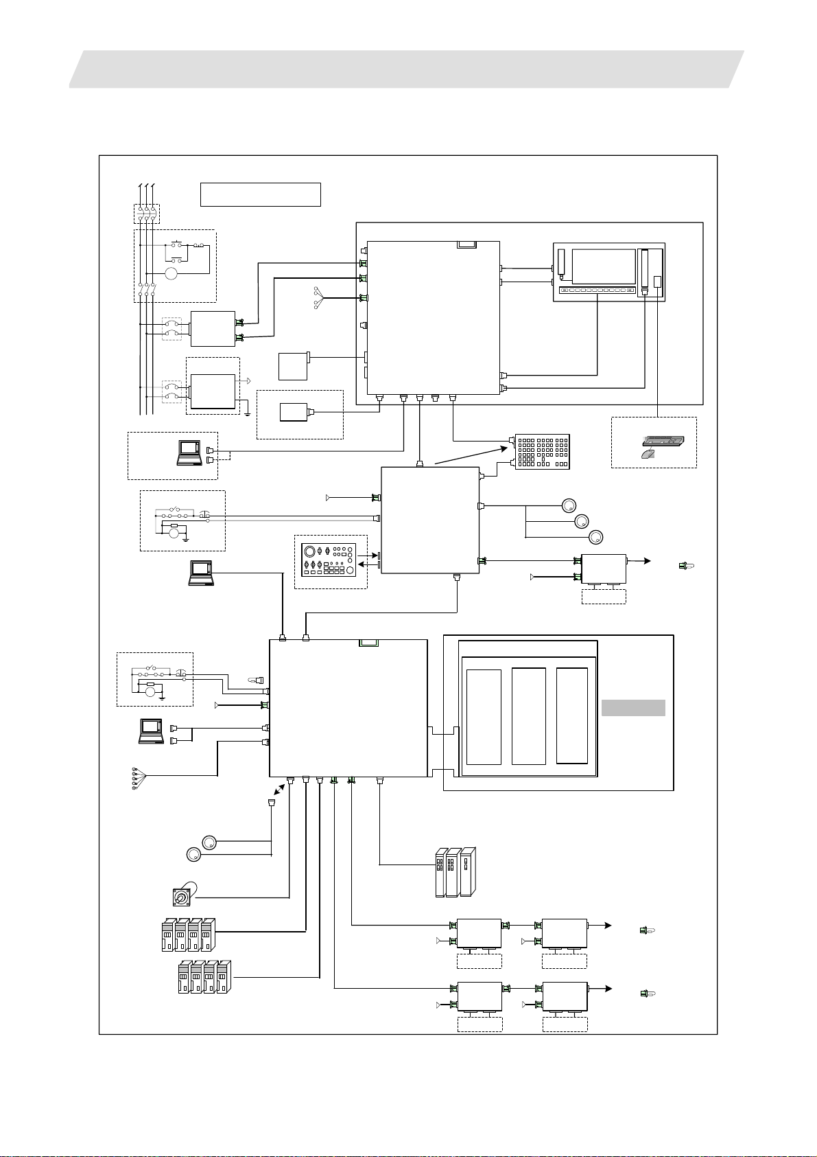
1.2.1 System Basic Configuration Drawing
Ethernet
hub
Personal
computer
Operation panel
I/O unit
with DIO
Manual pulse
penerator
MF MCODEDATA
TF TCODEDATA
SW1 SW9 SW10 SW11 SW12 SW13OV SL OVC SRN F1DSW8SW7SW6SW5SW4SW3SW2
100
10
1
-+
IC card I/F
1000
5000
10000
50000
100000
AL1 AL2 AL3 AL4 TAP DEN OP SA MA
SFLED29 LED30LED31LED32LED33LED34 LED35LED36
RAPID
STEP
R-POINTRETURN
JOG
X
HANDLE
MEM
Y
MDI
Z
TAPE
4
1STREFERENCEPOSITION
REACHED
+X +4+Z+Y
-X -4-Z-Y FEEDHOLDCYCLESTART
1.2 System Configuration
Remote I/O
unit
ON
DEGITAL SWITCH
OFF
Machine
FIN
MANUAL FEEDRATE
520
270
200
100
52
27
20
10
2
1
mm/mi n
0
720
1000
14000
4ZYX
RESET
CUTTINGFEEDRATEOVERRIDEMODE SELECTHANDLE/STEPMULTIPLICATION
100
110
90
80
120
130
70
1400
140
60
2000
2700
3700
5200
7200
10000
50
40
30
20
10
%
0
RAPIDTRAVERSEOVERRIDE
100
50
25
1
MSTLOCK
MACHINELOCK
150
160
170
180
190
DRYRUN
SINGLEBLOCK
200
EMERGENCYSTOP
Operation Panel
Emergency stop
Synchronous
feed encoder
Manual pulse generator
switch
Remote I/O
unit
Control unit
Data server
Emergency stop
switch
MDS-D-SVJ2/SPJ2 Series
Display unit
Servo/Spindle
drive unit
MDS-D/DH Series
Auxiliary axis Servo
drive unit
MR-J2-CT/CT4 Series
Keyboard
unit
Expansion
card
Expansion unit
Motor group
Auxiliary axis
2
1. 700 Series System Configuration
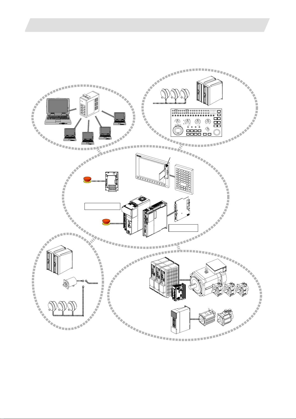
1.2.2 General Connection Diagram
1.2.2.1 Display Unit: FCU7-DA201-11/FCU7-DA211-11
1.2 System Configuration
RST
M
C
Circuit
breaker
RS-232C Device
OT release SW
Circuit break er
ON
M
C
MC
ACIN
R
A
FG
Dotted lines indicate the sections
prepared by machine tool builder
OF
F
24Vdc
Power Supply
DCOU
24Vdc
T
FG
FG
EMG
F120 Cable
LAN(user)
G300 Cable
F070 Cable
24Vdc
G031/G032 Cable
F070 Cable
24Vdc
Machine operation panel
(Max: 64/64)
Display Unit FCU7-DA201/DA211
IC memory card interface
C
INV
F
USB1
LCD
MENUKEY
FRONT_OUT
FCU7-KB021/KB022/KB041
G290 Cable
NCRST
F020/F021/F022(12V) Cable
G020/G021/G022(5V) Cable
MPG
RIO3
OPI
DCIN
SIO
LAN
G301
Cable
Operation Panel
DCIN
EMG
DX670/DX671
DX770/DX771
DI:CG31/CG33
DO:CG32/CG34
R300/R301Cable
G013Cable(max:20m)
PC Board
USB2
Can be added onto back
of keyboard
LAN
I/O Unit
FCU7-
Backlight
inverter
F480 Cable
G093 Cable
Keyboard Unit
G310 Cable
FCUA-R211 Cable(SH41 Cable)
F070 Cable
24Vdc
8.4-type/10.4-type
LCD
Menu key
G291 Cable
Manual Pulse generator HD60 (12V)
Remote I/O unit
RIO1
DX101
DCI
N
Machine I/O
IC memory card interface
PC Keyboard
Mouse
UFO-01-2Z9(5V)
RIO2
To next unit or
terminator
Max: 128/128
USB
USB3
interface
LAN1
OT release SW
EMG
R
A
FG
RS-232C Device
FCUA-R030 Cable
Sensor signals. 8 pints
Manual pulse generator
UFO-01-2Z9
(5V)
Sync. Encoder
F120 Cable
24Vdc
SIO x 2
EMG
terminator
G123
F070 Cable
F034/F035 Cabl e
SKIP
G023/G024 Cable
(Max:20m)
FCUA-R050,R054 Cable
SH21 Cable
OPI
EMG
DCIN
FCU7-MU001/MU002/MU011
SIO
SKIP
ENC
SV1
SV2
SH21 Cable
C
F
CNC Unit
RIO2
RIO1
FCUA-R211 Cable(SH41 Cable)
FCUA-R211 Cable(SH41 Cable)
OPT1
SDIO
G380/G395/G396
EXT-CON
24Vdc
24Vdc
Expansion Unit FCU7-EX89*
Slot1
MDS-D/
DH
Spindle/Servo
Drive Units
DX101
DX101
RIO2
RIO2
FCUA-R211
(SH41)
24Vdc
FCUA-R211
(SH41)
24Vdc
Remote I/O unit
RIO1
DCI
N
Machine I/O
Remote I/O unit
RIO1
DCI
N
Machine I/O
Slot2
Slot3
Remote I/O unit
RIO1
DX101
DCI
N
Machine I/O
Remote I/O unit
RIO1
DX101
DCI
N
Machine I/O
RIO2
RIO2
FieldBus OPT2 etc
To next unit or
terminator
Max: 256/256
To next unit or
terminator
Max: 256/256
3
1. 700 Series System Configuration
1.2.2.2 Display Unit: FCU7-DA315-11/FCU7-DA415-11/FCU7-DA445-11/FCU7-DA335-11/FCU7-DA435-11
1.2 System Configuration
RST
RS-232C
Device
Circuit breaker
ON
M
C
MC
M
C
Circuit
breaker
Circuit
breaker
OT release SW
R
A
Dotted lines indicate the sections
prepared by machine tool builder
OF
F
PD25/PD27
DCOUT
ACIN
ON/OFF
24Vdc
Power Supply
ACIN
EMG
FG
DCOUT
24Vdc
FG
FG
G031/G032 Cable
F120 Cable
LAN(user)
G300 Cable
F110 Cable
G171 Cable
O
N
OF
F
Hard Disk Unit
FCU7-HD001-1
HDD
Can be added onto
back of keyboard
(OPTION)
FDD
24Vdc
Machine operation panel
(Max: 64/64)
G170 Cable
F140 Cable
F070Cable
Display Unit FCU7-DA315/DA415/DA445/DA335/DA435
CF01
DCIN
CF24
ON/OFF
EMG
HDD
CF25
F130 Cable
FD
SIO
D
Operation Panel
DCIN
EMG
DX670/DX671
IC memory card interface
PC Board
LAN
USB1
USB2
G301
Cable
Can be added onto
back of keyboard
LAN
I/O Unit
FCU7-
C
F
INV
LCD
MENUKEY
FRONT_OU
T
FCU7-KB021/KB022/KB041
G290 Cable
F020/F021/F022(12V) Cable
G020/G021/G022(5V) Cable
MPG
G310 Cable
NCRST
Backlight inverter
F480 Cable
G093 Cable
Keyboard Unit
DX770/DX771
DI:CG31/CG33
DO:CG32/CG34
R300/R301 Cable
G013 Cable(max:20m)
RIO3
OPI
FCUA-R211 Cable(SH41 Cable)
F070 Cable
24Vdc
10.4-type/15-type
LCD
Menu key
G291 Cable
Manual Pulse generator HD60 (12V)
Remote I/O unit
RIO1
DX101
DCI
N
Machine I/O
IC memory card interface
PC Keyboard
Mouse
UFO-01-2Z9(5V)
RIO2
To next unit or
terminator
Max: 128/128
USB interface
USB
LAN1
OT release SW
R
A
FG
RS-232C Device
FCUA-R030 Cable
Sensor signals. 8 pints
Manual pulse generator
UFO-01-2Z9
(5V)
Sync. Encoder
EMG
F120 Cable
24Vdc
SIO x 2
EMG
terminator
G123
F070 Cable
F034/F035 Cable
SKIP
G023/G024 Cable
(Max:20m)
FCUA-R050,R054 Cable
SH21 Cable
OPI
EMG
DCIN
FCU7-MU001/MU002/MU011
SIO
SKIP
ENC
SV2
SV1
SH21 Cable
C
F
CNC Unit
/MA011
RIO2
RIO1
OPT1
FCUA-R211 Cable(SH41 Cable)
FCUA-R211 C able(SH41 Cable)
SDIO
G380/G395/G396
EXT-CON
24Vdc
24Vdc
Expansion Unit FCU7-EX89
MDS-D/DH
Spindle/Servo
Drive Units
RIO2
RIO2
Slot2
FCUA-R211
(SH41)
24Vdc
FCUA-R211
(SH41)
24Vdc
Slot1
Remote I/O unit
RIO1
DX101
DCIN
Machine I/O
Remote I/O unit
RIO1
DX101
DCIN
Machine I/O
Slot3
Remote I/O unit
RIO1
DX101
DCIN
Machine I/O
Remote I/O unit
RIO1
DX101
DCIN
Machine I/O
RIO2
RIO2
*
FieldBus OPT2 etc
To next unit or
terminator
Max: 256/256
To next unit or
terminator
Max: 256/256
4

1. 700 Series System Configuration
1.2 System Configuration
1.2.3 List of Configuration Units
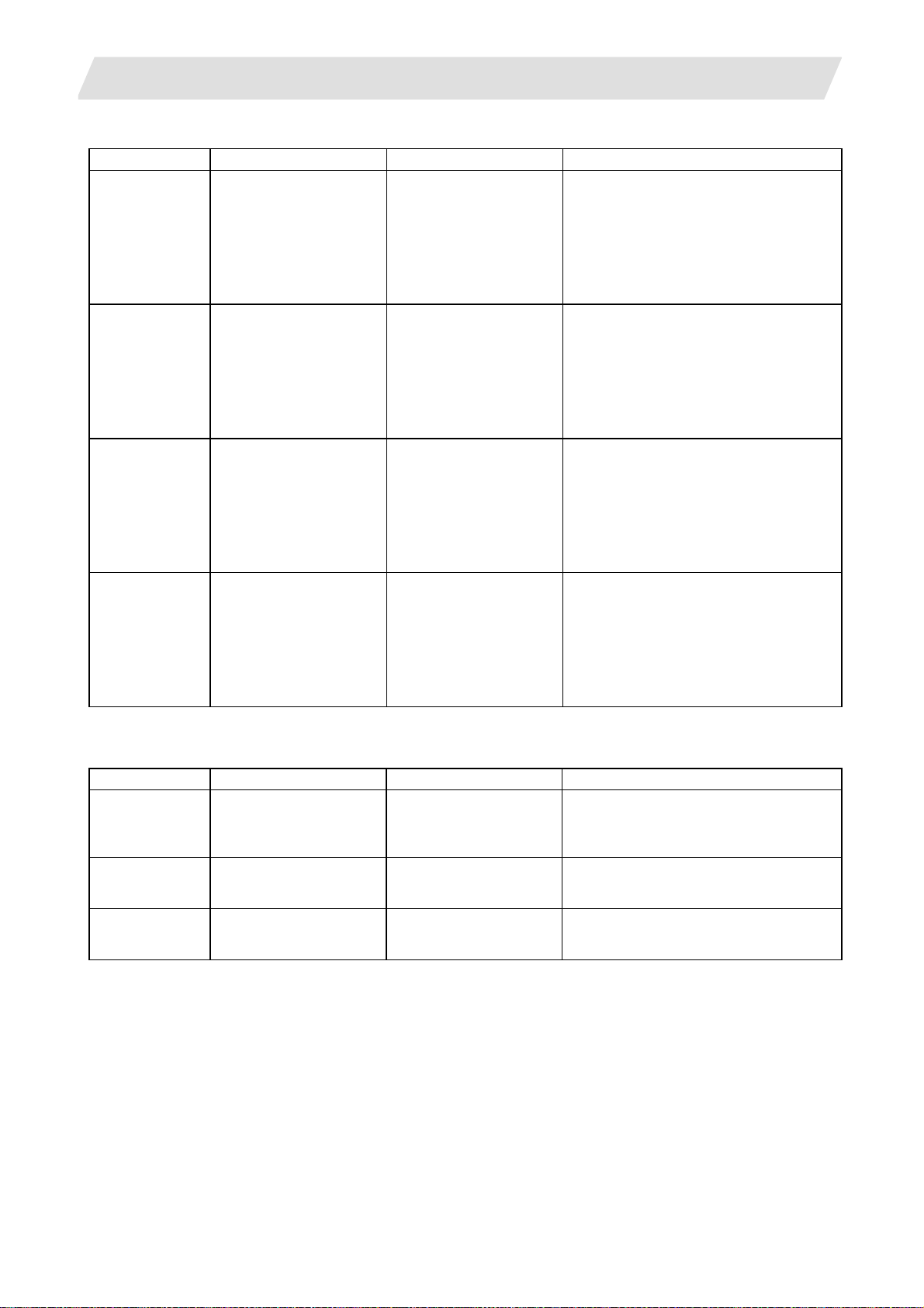
1.2.3.1 Control Unit: FCU7-MU001/FCU7-MU002/FCU7-MU011/FCU7-MA011
Type Function Configuration element Details
FCU7-MU001 M700 control unit set Main control card (HN115)
CPU card (HN122)
Display/setting card (HN091)
M720 system compatible
unit
FCU7-MU002 M700 control unit set Main control card (HN116)
M720 system compatible
unit
FCU7-MU011 M700 control unit set Main control card (HN115)
M730 system compatible
unit
FCU7-MA011 M700 control unit set Main control card (HN145)
M750 system compatible
unit
24V input power supply card (HN081)
Memory card (HN482)
G123 cable
Case set
(CPU card section is within HN116.)
Display/setting card (HN091)
24V input power supply card (HN081)
Memory card (HN482)
G123 cable
Case set
CPU card (HN123)
Display/setting card (HN091)
24V input power supply card (HN081)
Memory card (HN484)
G123 cable
Case set
CPU card (HN123)
Display/setting card (HN091)
24V input power supply card (HN081)
Memory card (HN484)
G123 cable
Case set
Export Trade Control Ordinance
and Foreign Trade Ordinance
noncompliant unit
Export Trade Control Ordinance
and Foreign Trade Ordinance
noncompliant unit
Export Trade Control Ordinance
and Foreign Trade Ordinance
noncompliant unit
Export Trade Control Ordinance
and Foreign Trade Ordinance
compliant unit
5

1. 700 Series System Configuration
1.2 System Configuration
1.2.3.2 Display Unit: FCU7-DA201/FCU7-DA211/FCU7-DA315/FCU7-DA415/FCU7-DA445/FCU7-DA335/FCU7-DA435
Type Function Configuration element Details
FCU7-DA201-xx 8.4-type color LCD
display unit
WindowsCE compatible
(separated type)
FCU7-DA211-xx 10.4-type color LCD
display unit
WindowsCE compatible
(separated type)
FCU7-DA315-xx 10.4-type color LCD
display unit
WindowsXPe compatible
(separated type)
FCU7-DA415-xx 10.4-type color LCD
display unit
High-performance
version
WindowsXPe compatible
(separated type)
FCU7-DA445-xx 10.4-type color LCD
display unit (Wide view
angle)
High-performance
version
WindowsXPe compatible
(separated type)
FCU7-DA335-xx 15-type color LCD
display unit
WindowsXPe compatible
(separated type)
FCU7-DA435-xx 15-type color LCD
display unit
High-performance
version
WindowsXPe compatible
(separated type)
8.4-type (VGA) LCD, Escutcheon
Control card (ROD-6204-MIT1CE)
G093 cable
G291 cable
F480 cable
with front IC card (FCU7-EP102)
10.4-type (VGA) LCD, Escutcheon
Control card (ROD-6204-MIT1CE)
G093 cable
G291 cable
F480 cable
with front IC card (FCU7-EP102)
10.4-type (VGA) LCD, Escutcheon
Control card (MIC73M2)
G093 cable
G291 cable
F480 cable
with front IC card (FCU7-EP102)
10.4-type (VGA) LCD, Escutcheon
Control card (MIP12M2)
G093 cable
G291 cable
F480 cable
with front IC card (FCU7-EP102)
10.4-type (VGA) LCD, Escutcheon
Control card (MIP12M2)
G093 cable
G291 cable
F480 cable
with front IC card (FCU7-EP102)
15-type (XGA)LCD, Escutcheon
Control card (MIC73M2)
with front IC card (FCU7-EP102)
15-type (XGA)LCD, Escutcheon
Control card (MIC73M2)
with front IC card (FCU7-EP102)
Control card 24VDC input
Mounting method:
Mount on front panel
Control card 24VDC input
Mounting method:
Mount on front panel
Celeron 733MHz
Control card: 24VDC input
Mounting method:
Mount on front panel
Use PD25/PD27 for power
supply
Pentium III 1.26GHz
Control card: 24VDC input
Mounting method:
Mount on front panel
Use PD25/PD27 for power
supply
Pentium III 1.26GHz
Control card: 24VDC input
Mounting method:
Mount on front panel
Use PD25/PD27 for power
supply
Celeron733MHz
Control card: 24VDC input
Mounting method:
Mount on front panel
Use PD25/PD27 for power
supply
Pentium III 1.26GHz
Control card: 24VDC input
Mounting method:
Mount on front panel
Use PD25/PD27 for power
supply
(Note 1) FCU7-DAxxx-01: without MITSUBISHI logo; without touch panel; with menu key
FCU7-DAxxx-11: with MITSUBISHI logo; without touch panel; with menu key
FCU7-DAxxx-21: without MITSUBISHI logo; with touch panel; with menu key
FCU7-DAxxx-31: with MITSUBISHI logo; with touch panel; with menu key
(FCU7-DA201-xx: without touch panel type only)
FCU7-DAxxx-61: without MITSUBISHI logo; with touch panel: without menu key
FCU7-DAxxx-71: with MITSUBISHI logo; with touch panel: without menu key
(Note 2) OS and S/W are not included for the types of display units listed above.
6
1. 700 Series System Configuration
1.2 System Configuration
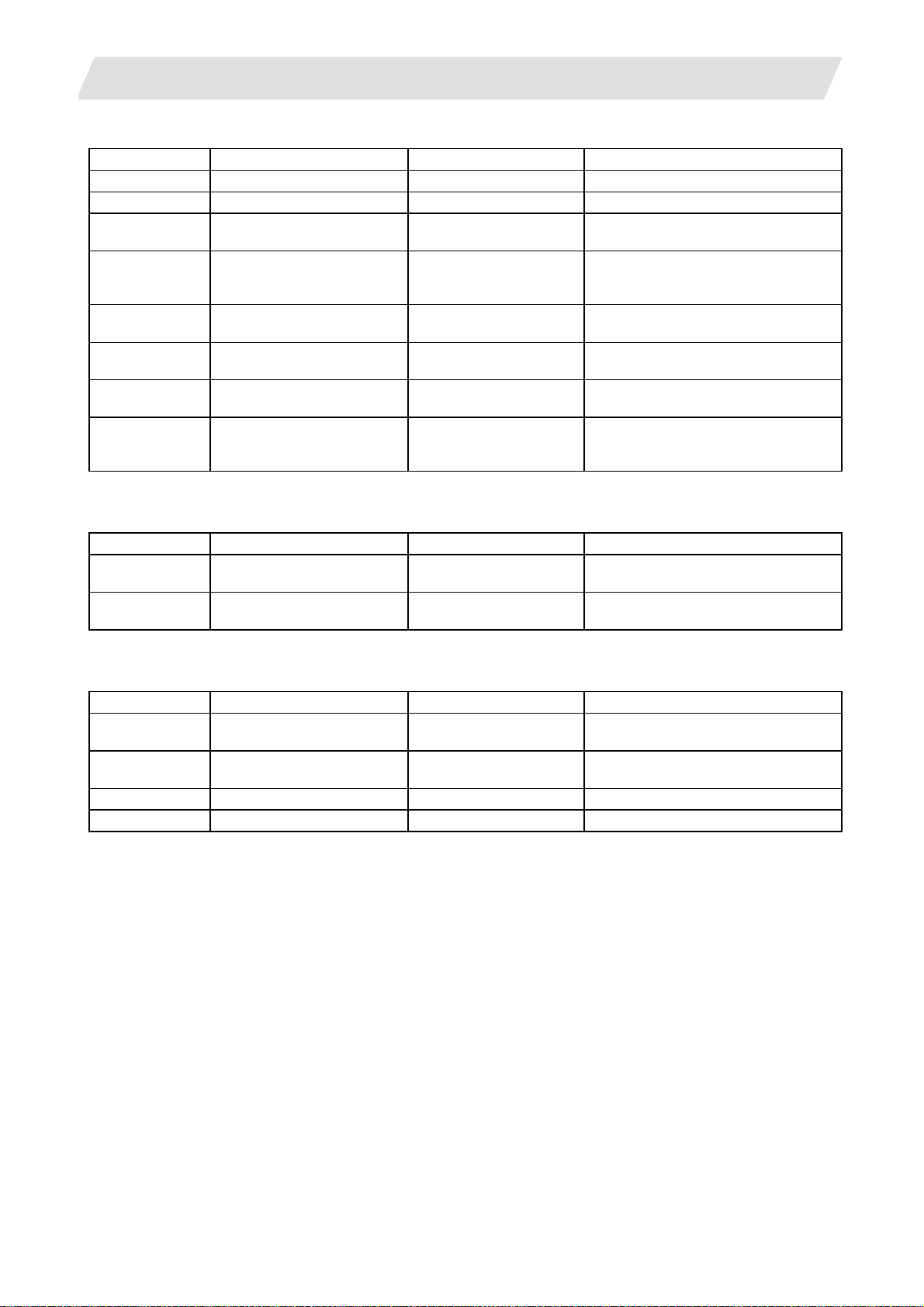
1.2.3.3 Operation Panel I/O Unit: FCU7-DX670/FCU7-DX671/FCU7-DX770/FCU7-DX771
Type Function Configuration element Details
FCU7-DX670 Sink/source input + sink
output
Mounting bracket
FCU7-DX671 Sink/source input + source
output
Mounting bracket
FCU7-DX770 Sink/source input + sink
output
Mounting bracket
FCU7-DX771 Sink/source input + source
output
Mounting bracket
HN391
G301 cable
G310 cable
Terminator R-TM
HN392
G301 cable
G310 cable
Terminator R-TM
HN391+HN396
G301 cable
G310 cable
Terminator R-TM
HN392+HN397
G301 cable
G310 cable
Terminator R-TM
DI/DO = 32 points/32 points
(output 60mA)
Output insulation type (Note 1)
Display-main body relay I/F
Manual pulse generator 3ch
Emergency stop input
Remote I/O 1ch (160 points/160 points)
DI/DO = 32 points/32 points
(output 60mA)
Output insulation type (Note 1)
Display-main body relay I/F
Manual pulse generator 3ch
Emergency stop input
Remote I/O 1ch (160 points/160 points)
DI/DO = 64 points/64 points
(output 60mA)
Output insulation type (Note 1)
Display-main body relay I/F
Manual pulse generator 3ch
Emergency stop input
Remote I/O 1ch (128 points/128 points)
DI/DO = 64 points/64 points
(output 60mA)
Output insulation type (Note 1)
Display-main body relay I/F
Manual pulse generator 3ch
Emergency stop input
Remote I/O 1ch (128 points/128 points)
1.2.3.4 Keyboard Unit : FCU7-KB021/FCU7-KB022/FCU7-KB041
Type Function Configuration element Details
FCU7-KB021 8.4-type display keyboard Escutcheon, key switch Connect with G290 cable from display unit.
ONG layout for machining
center
FCU7-KB022 8.4-type display keyboard Escutcheon, key switch Connect with G290 cable from display unit.
ONG layout for lathe Control card, G290 cable Mounting method: Mount on front panel
FCU7-KB041 10.4-type display keyboard Escutcheon, key switch Connect with G290 cable from display unit.
ABC layout Control card, G290 cable Mounting method: Mount on front panel
Control card, G290 cable Mounting method: Mount on front panel
7
1. 700 Series System Configuration
1.2 System Configuration
1.2.3.5 Remote I/O Unit: FCUA-DX100/DX110/DX120/DX140/DX101/DX111/DX121/DX141
Type Function Configuration element Details
FCUA-DX100 Sink/source input + sink output RX311 DI/DO = 32 points/32 points
FCUA-DX110 Sink/source input + sink output RX311+RX321-1 DI/DO = 64 points/48 points
FCUA-DX120 Sink/source input + sink output
+ analog output
FCUA-DX140 Sink/source input + sink output
+ analog input/output
FCUA-DX101 Sink/source input + source
output
FCUA-DX111 Sink/source input + source
output
FCUA-DX121 Sink/source input + source
output + analog output
FCUA-DX141 Sink/source input + source
output + analog input/output
RX311+RX321 DI/DO = 64 points/48 points
+ analog output 1 point
RX311+RX341 DI/DO = 32 points/32 points
+ analog input 4 points
+ analog output 1 point
RX312 DI/DO = 32 points/32 points
RX312+RX322-1 DI/DO = 64 points/48 points
RX312+RX322 DI/DO = 64 points/48 points
+ analog output 1 point
RX312+RX341 DI/DO = 32 points/32 points
+ analog input 4 points
+ analog output 1 point
1.2.3.6 Scan I/O: HR357/HR347
Type Function Configuration element Details
HR357 Scan I/O (source) HR357 Scan DI/DO = 64 points/64 points
DI/DO = 32 points/32 points
HR347 Scan I/O (sink) HR347 Scan DI/DO = 64 points/64 points
DI/DO = 32 points/32 points
1.2.3.7 Card-sized I/O Card: HR361/HR371/HR381/HR383
Type Function Configuration element Details
HR361 DI16 (sink/source)
+DO16 (sink)
HR371 DI32 (sink/source)
+DO16 (source)
HR381 AO x 1 HR381 AO x 1
HR383 AI x 4+AO x 1 HR383 AI x 4+AO x 1
HR361 DI/DO = 16 points/16 points
HR371 DI/DO = 16 points/16 points
8
1. 700 Series System Configuration
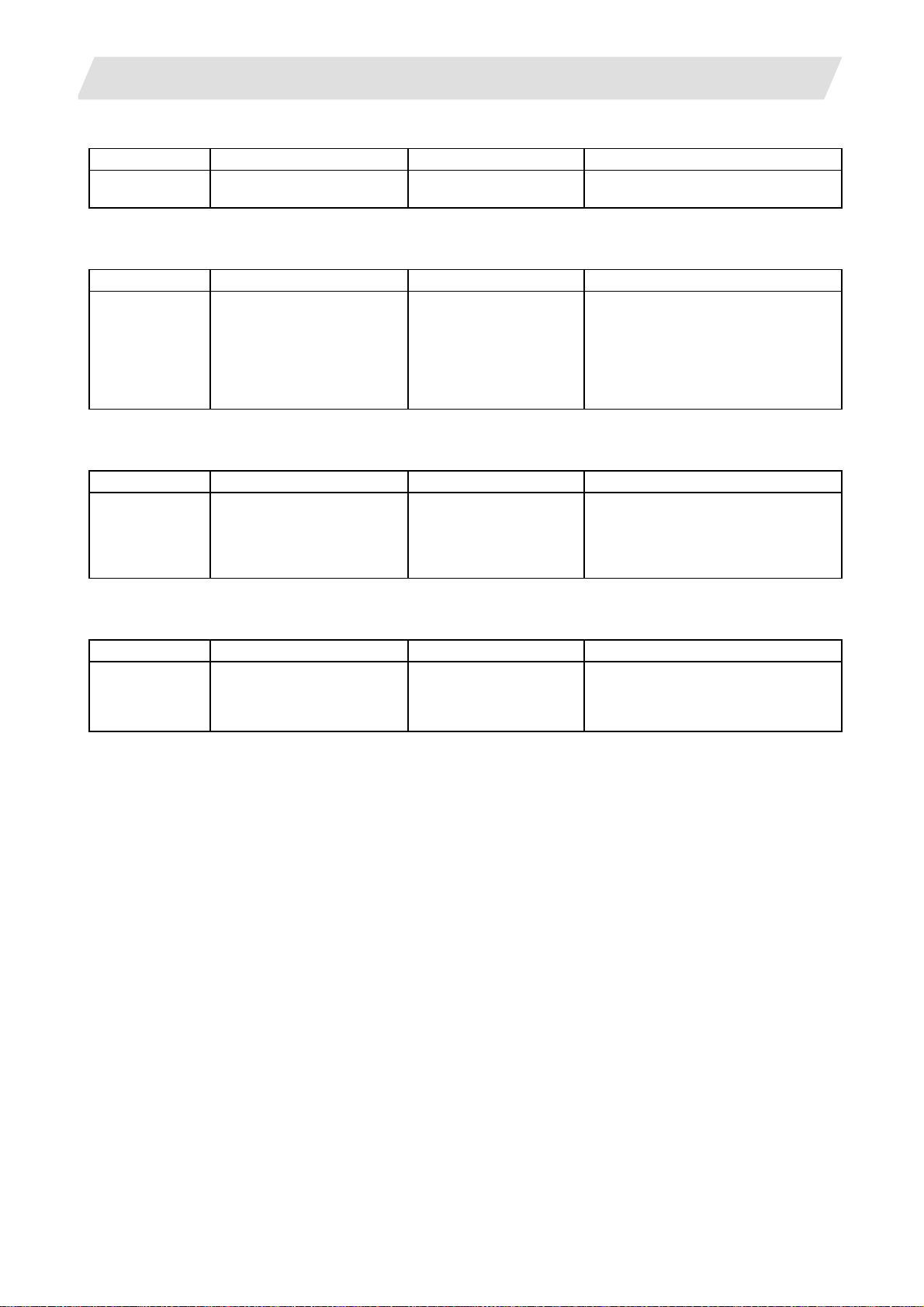
1.2.3.8 Extended I/O Card: QY231
Type Function Configuration element Details
QY231 Sink/source input + source
output
QY231 Sink/source input 64 points
1.2.3.9 Front IC Card Interface: FCU7-EP102-1 (option)
Type Function Configuration element Details
FCU7-EP102-1 Memory card slot x 1ch
USB x 1ch (Ver1.1, Series "A"
Connectors)
Front IC card I/F
(USB-PC-CARD-TYPE-A)
1.2.3.10 Hard Disk Unit: FCU7-HD001-1
Type Function Configuration element Details
FCU7-HD001-1 External memory device Hard disk
Mounting plate,
cushioning rubber
F140 cable (50cm)
1.2.3.11 Floppy Disk Unit: FCU7-FD221
Type Function Configuration element Details
FCU7-FD221-1 External memory device Floppy disk drive
Mounting plate for
pendant box
F130 cable (1m)
1.2 System Configuration
+ source output 48 points
Connect with G291 cable from display
unit.
PC Card Standard ATA compliant
memory card TYPEI, TYPEII only
5VDC: max 220mA
USB(Ver1.1)I/F
(5VDC, max 100mA)
Display unit
Connect with
FCU7-DA315/DA415/DA445.
Installation method: Mount on the back
of FCU7-KB041
Display unit
Connect with FCU7-DA315/DA415/
DA445
9
1. 700 Series System Configuration
1.2.3.12 Expansion Unit: FCU7-EX891
Type Function Configuration element Details
FCU7-EX891 Expansion unit x 1slot HR891
Mounting plate, case set
(Note1) Only one expansion unit can be mounted.
1.2.3.13 Expansion Card
Type Function Configuration element Details
FCU7-HN551 Optical servo communication
I/F × 1ch
FCU7-HN552 Optical servo communication
I/F × 2ch
FCU7-HN571
FCU7-HN576
PROFIBUS-DP × 1ch
CC-Link × 1ch
HN551
HN552
HN571
HN576
1.2.3.14 External Power Supply Unit: PD25/PD27
Type Function Configuration element Details
PD25 External power supply with
power supply ON/OFF
function
PD27 External power supply with
power supply ON/OFF
function
Power supply card
Case set
Power supply card
Case set
1.2 System Configuration
One expansion card HN5xx can be
mounted additionally.
Installation method: Mount on the side
of NC unit
Expansion unit
Connect with FCU7-EX891.
Installation method: Insert in expansion
unit and fix with front cover
Input 200VAC
Output 24VDC (3A)
Input 200V to 400VAC
Output 24VDC (8A)
10
2. Maintenance Screens
2.1 Input/Output Screen
2. Maintenance Screens
2.1 Input/Output Screen
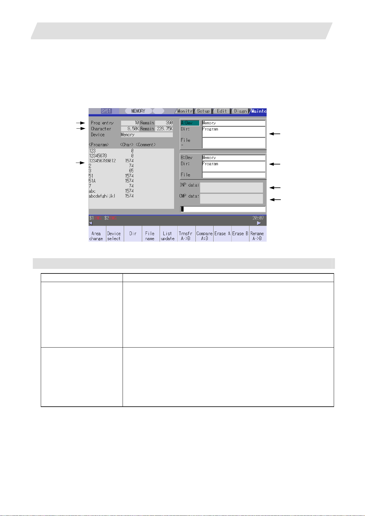
The Input/Output screen is used to carry out NC data input/output between the NC internal memory and the
external input/output devices.
Here, the hard disk built into the NC device is also treated as external devices.
In 70 series, only "Memory", "Memory card", "Serial", "Ethernet" and "Anshin-net server" can be used.
(1)
(2)
(4)
(3)
Display items
Display item Details
(1) Number of programs
registered and remainder
(Note 1)
(2) Number of memory
characters and remainder
(Note 1)
(5)
(6)
(7)
This displays the registration information of machining program of the selected
device.
Number of programs registered :
This displays the number of programs previously registered as user machining
programs.
Remainder :
This displays the remaining number of programs that can be registered.
When "Memory" is selected as the device, the total of the number of programs
registered and the remainder is the maximum number of registrations set in the
specifications.
This displays the number of characters of the machining program of the selected
device.
Number of memory characters :
This displays the number of characters previously registered as user machining
programs.
Remainder :
This displays the remaining number of characters that can be registered. The total
of the number of memory characters and the remainder is the maximum number of
memory characters set in the specifications.
11
2. Maintenance Screens
2.1 Input/Output Screen
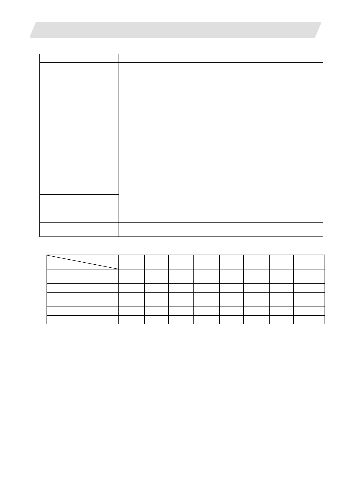
Display items Details
List (Note 2)
(3)
(4) File setting column A
(5) File setting column B
(6) Input data This displays the data being transferred.
(7) Comparison data This displays the data being compared. If an error occurs during comparison, the
(Note 1) Depending on the device, some items are not displayed.
Device
Display item
Number of programs
registered
Remainder
Number of memory
characters
Remainder
List
* : When the Ethernet parameter "#97*1 Host n no total siz" is set to 1, the number of host memory
characters will not appear.
(Note 2) The list does not appear when using serial.
This displays a contents list (directory and file name) of the directory in the setting
column (file setting column A or B) where the cursor is currently located.
Program :
When "Memory" is selected for the device, this displays the file name (program No.)
of the machining programs already registered. The file names are displayed in
order from the smallest number, from 1 to 99999999. When a device other than
memory is selected, this displays the file name and directory to be included in the
directory that is set in the current setting column.
When the number of characters exceeds 12, the excess is indicated as "*".
Character :
The size of each file (when memory is selected for the device, the number of
characters in the machining program). When directory is selected, this displays
"DIR".
Comment :
This displays the comment (up to 17 alphanumeric characters and symbols) of
each file.
The date which the file is updated is displayed for the HD, FD, memory card, DS or
Ethernet.
When the number of characters exceeds 17, the excess is not displayed.
This sets the device, directory, and file name of the target file for transfer, compare,
erasing, etc., operations.
When transferring, the file name of the transfer origin file is set. When renaming, the
file name before renaming is set. When erasing, the erasing range is set. When the
number of characters exceeds 28, the excess is not displayed.
block with the error is displayed.
×
×
×
×
Memory
card
{ { { {
{ {
{ {
{ { { {
DS Ethernet FD
{ *
×
{ : Displayed × : Not displayed
Memory HD Serial
{ {
{
{ {
{ {
{ {
× × × × × × ×
{
{
Anshin-net
server
×
×
×
×
12

2. Maintenance Screens
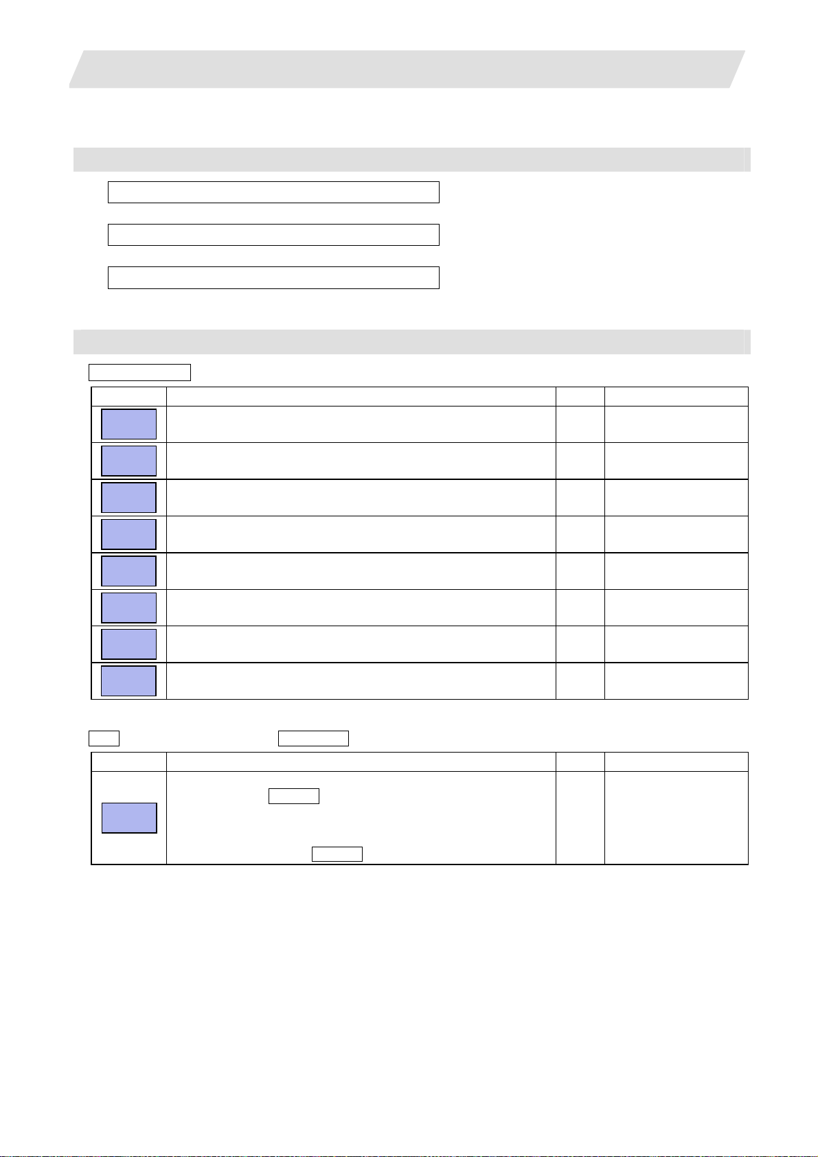
Menus
Menu Details Type Reference
Area
change
Device
select
Dir
File
name
List
update
Transfr
→B
A
Compare
A:B
Erase A
Erase B
Rename
→B
A
Comment
nondisp
Dir
create
Merge
B
→A
FD
format
MemCrd
format
DS
format
Warning
cancel
Stop
This changes the setting area to file setting column A (transfer origin)
or file setting column B (transfer destination). The display of the valid
area (A or B) is highlighted.
This displays the submenu of the machining program storage area.
When the submenu is selected, the device is confirmed, and if a
directory exists it is set in the root.
The memory is selected as the default.
This menu sets the directory that carries out input/ output operations,
and is on standby for input. Note that when memory is selected for the
device, the directory can be selected from the submenu.
This menu sets the file name that carries out input/ output operations,
and is on standby for input. When memory is selected for the device,
setting is not necessary if the directory is not the program.
This updates the list. The list of the directly selected in the currently
valid file setting column (A/B) is updated.
This copies the file in file setting column A (transfer origin) to the file
setting column B (transfer destination). (The transfer origin file is not
changed.) A message appears during transfer and when the transfer
is completed.
This compares the files in file setting column A (transfer origin) and file
setting column B (transfer destination).
This erases the file in file setting column A.
(Note) The NC memory (excluding programs), serial and Ethernet
This erases the file in file setting column B.
(Note) The NC memory (excluding programs), serial and Ethernet
This changes the name of the file in file setting column A (transfer
origin) to the name of the file in file setting column B (transfer
destination).
(Note) The same device must be selected for A and B.
The NC memory (excluding programs) and serial cannot be renamed.
This changes whether to show or hide the comment field. B
This creates a new directory in the directory of the currently valid file
setting column (A/B).
The directory can be created when HD, FD, memory card or DS is
selected for the device.
The file contents in the file setting column B are added to the file in the
file setting column A. (The file in the file setting column B is not
changed.)
(Note) The NC memory (excluding programs), serial and Ethernet
This formats the FD.
This menu is only for 700 series.
The formats the front IC card.
This formats the NC compact flash memory.
This menu is only for 700 series.
This cancels a warning from network service. C
This interrupts the process (transfer, compare, etc.) during execution. C -
(host file) cannot be erased.
(host file) cannot be erased.
(host file) cannot be merged.
A
2.1 Input/Output Screen
C 2.1.1 Changing the Valid
Area
A 2.1.2 Selecting a
Device, Directory, and
File
A
A
C -
B 2.1.3 Transferring a File
C 2.1.4 Comparing Files
(Compare)
B
B
B
A
B
2.1.5 Formatting an
A
External Device
A
13
2. Maintenance Screens
2.1 Input/Output Screen
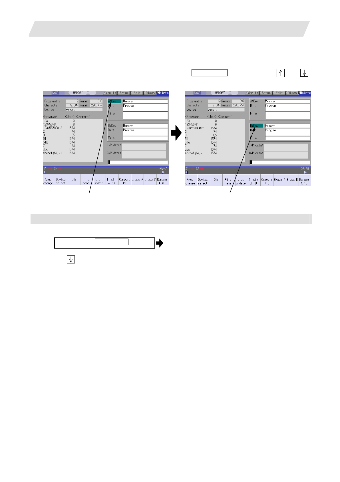
2.1.1 Changing the Valid Area
When setting the file setting field A or B device, directory and file name on this screen, the area containing
these must be valid.
The display area can be changed by pressing the menu key ( Area change ) or the cursor key
After changing, the data setting operation is valid in that area.
and .
File setting field A is valid. File setting field B is valid.
Changing the valid file setting field
When file setting field A (top) is valid
(1)
Press the menu Area change .
This can also be changed with the cursor
key
.
The file setting field B (bottom) is validated.
14
2. Maintenance Screens
2.1.2 Selecting a Device, Directory and File
File selection sequence
Designate the device where the target file is located.
↓
Designate the directory with a full path.
↓
Designate the file name.
Menu used
Device select menu's submenus
Menu Details Type Reference
Memory
HD
Serial
Memory
card
DS
Ethernet
FD
Anet
server
Dir (other than memory) and File name menu submenus
This selects the NC memory (program, parameter, user PLC, NC
data).
This selects the hard disk.
This menu is only for 700 series.
This selects the RS-232C device (PC, tape, etc.). C -
This selects the front IC card. C -
This selects the NC compact flash memory.
This menu is only for 700 series.
This selects the Ethernet-connected host computer. C -
This selects the floppy disk.
This menu is only for 700 series.
This selects the Anshin-net server. C
2.1 Input/Output Screen
Select from the sub menu.
→
Input the full path or select from the list.
→
→ Input the file name or select from the list.
C -
C -
C -
C -
Menu Details Type Reference
From
list
The cursor appears in the list display. The list contents can be
selected with the INPUT key.
When a directory is selected, the contents of the selected directory
are displayed in the list. Continued selection is possible.
When a file name is selected, the file name is temporarily displayed in
the input area. When the INPUT key is pressed again, it is fixed.
A -
15
2. Maintenance Screens
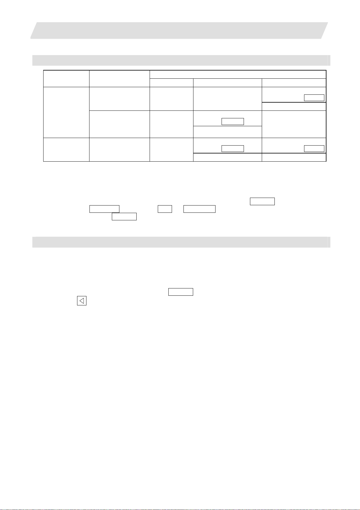
Selecting methods for device, directory, and file name
Device Designation target file
NC memory Select from the
Other than the
• Machining program
User macro
•
•
Fixed cycle
machining program
Device Directory File name
submenu
Select from the list
Select from the
submenu
2.1 Input/Output Screen
Designation method
-
(Default)
Key input in the input area,
and press INPUT
Select from the submenu
Key input in the input
area, and press INPUT
-
(Fixed)
Other than the
NC memory
Select from the list Select from the list
All Select from the
submenu
Key input in the input area,
and press INPUT
Key input in the input
area, and press INPUT
The device can be selected from the submenu. (The devices that can be used will differ depending on the
specifications.)
One of the following methods can be used to designate the directory (for devices other than the NC memory)
and file name.
• Set the directory path (full path) or file name in the input area, and press the INPUT key.
• Press submenu From list of the menu Dir or File name . Move the cursor to the target directory or
file name, and press the INPUT key.
A wild card (*) can be used when selecting a file name.
Notes when selecting a file
(1) During directory and file name setting, the designated directory, path or file name will be set, even if it
does not actually exist. This will not cause an error. Note that the previously set directory is overwritten.
(2) When a file in the NC memory other than a machining program is designated, it is not necessary to set the
file name. (The file name is fixed.)
(3) When a file name is selected from the menu, it first is displayed in the input area. However, at this time the
file name has not yet been fixed. Press the INPUT key again to fix the file name.
(4) When the
key is pressed when setting a file name, the file name in the input area is erased.
(5) When a fixed cycle program is designated, the basic common parameters "#1166 fixpro" must be set.
Select "Memory" for the device, and "Program" for the directory.
16
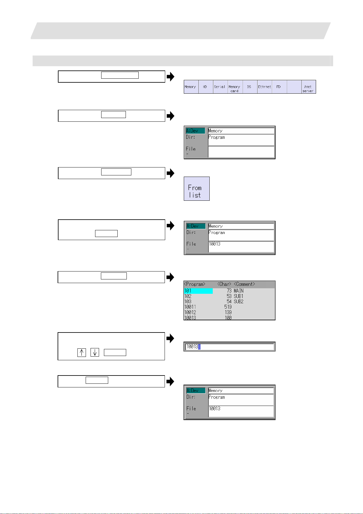
2. Maintenance Screens
Selecting an NC memory program
(1)
Press the menu Device select .
(2)
Press the menu Memory .
(3)
Press the menu File name .
<When inputting the file name from the input area>
(4)
Input the file name
10013 INPUT
2.1 Input/Output Screen
The following menu appears.
(When specifications of all devices is valid.)
"Memory" appears in the device name, and the default
"Program" appears in the directory.
The following menu appears.
<When selecting the file name from the list>
(4)-1
Press the menu From list .
(4)-2 Move the cursor to file name to be
selected, and fix.
, , INPUT
(4)-3
Press the INPUT key.
The cursor appears in the list.
The selected file name appears in the input area.
The selected file name appears.
17
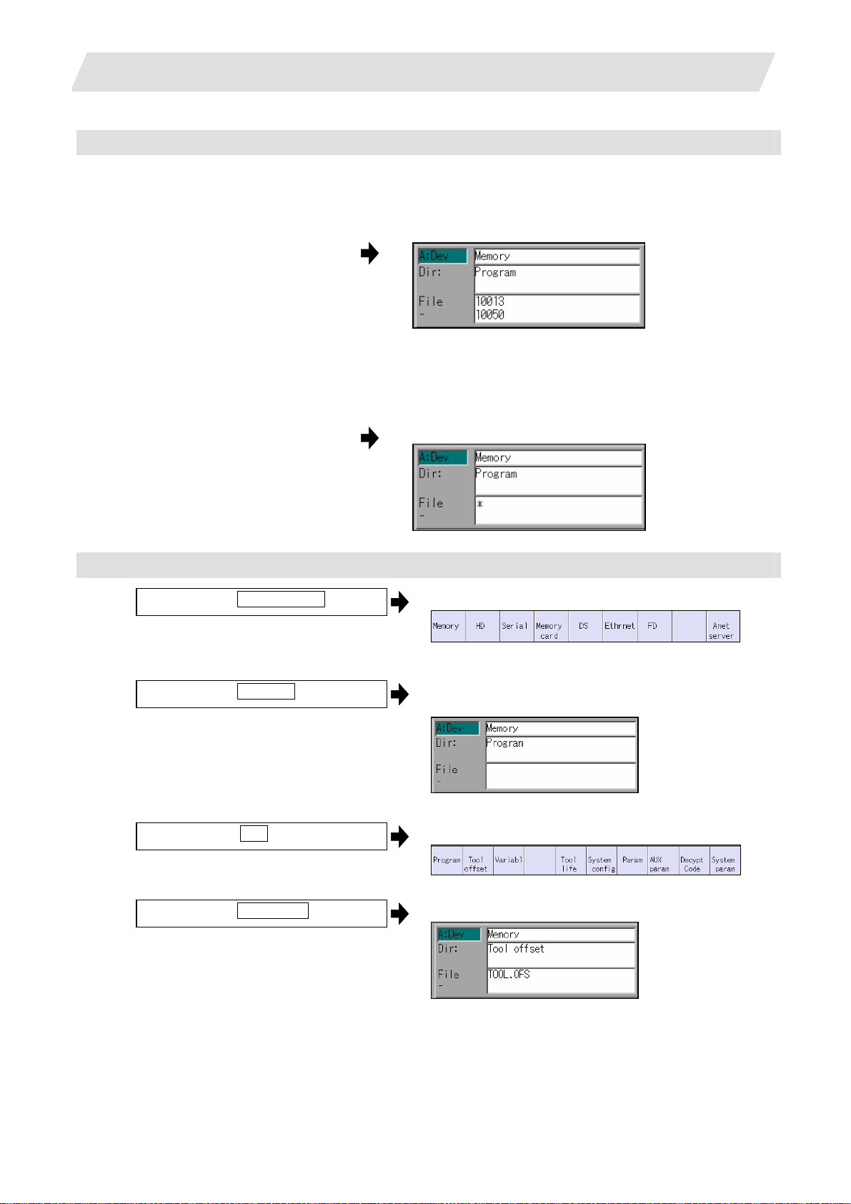
2. Maintenance Screens
Designating multiple files
(1) Designating multiple serial files
Multiple serial files can be transferred, compared and erased in the file setting column A. Set as follows
in this case.
File : First file name
- : Last file name
(2) Using a wild card
A wild card (*) can be used in the file name.
(Note) When serial or Anshin-net server is used, multiple files cannot be compared.
:
File
-
*
All files will be selected.
2.1 Input/Output Screen
Selecting an NC memory file other than a program
(1)
Press the menu Device select .
(2)
Press the menu Memory .
(3)
Select the menu Dir .
(4)
Press the menu Tool offset .
The following menu appears.
(When specifications of all devices is valid.)
"Memory" appears in the device name, and "Program"
appears as the default in the directory.
The following menu appears.
The directory and file name appear.
(Note) The file name for each directory is fixed. Refer to "2.1.6 List of file names" for the file names.
18
2. Maintenance Screens
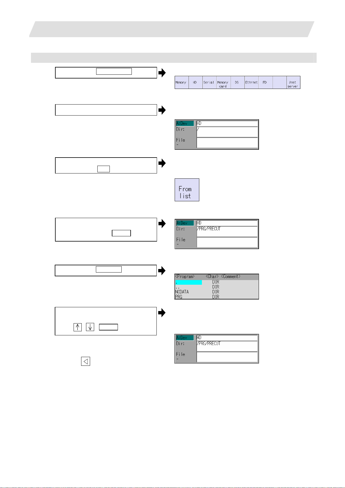
Selecting a device file other than the NC memory
(1)
Press the menu Device select .
(2) Select a device.
(3)
Designate the directory.
Select the menu Dir
2.1 Input/Output Screen
The following menu appears.
(When specifications of all devices is valid.)
The device name appears. The root directory is
selected as the default.
The mode changes to the mode for inputting the
directory name.
The following menu appears.
<When inputting the directory from the input area>
(4)
Input the directory path as a full path.
/PRG/PRECUT INPUT
<When selecting the directory from the list >
(4)-1
Press the menu From list
(4)-2 Move the cursor to directory to be
selected, and fix.
, , INPUT
Repeat this operation until the target
directory is reached.
When the target directory is reached,
press the
inputting the directory.
key and quit the mode for
The cursor appears in the list.
The selected directory appears in the data setting
column.
The contents of the selected directory appear in the
list.
19
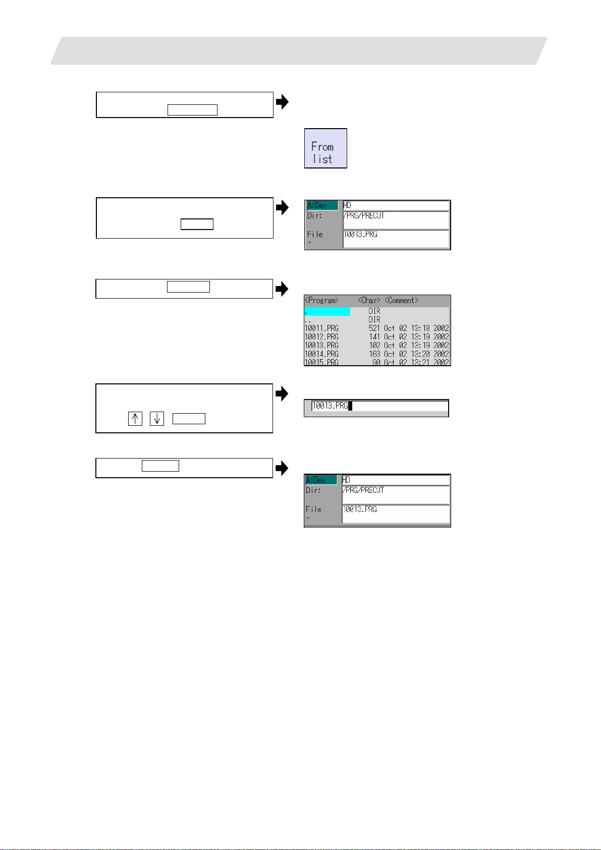
2. Maintenance Screens
(5) Designate the file name.
Press the menu File name
<When inputting the file name from the input area>
(6)
Input the file name
10013.PRG INPUT
2.1 Input/Output Screen
The mode changes to the mode for inputting the file
name.
The following menu appears.
<When selecting the file name from the list>
(6)-1
Press the menu From list .
(6)-2 Move the cursor to file name to be
selected, and fix.
, , INPUT
(6)-3
Press the INPUT key.
The cursor appears in the list.
The selected file name appears in the input area.
The selected file name appears.
20
 Loading...