

Mitsubishi WD-65731 Owner’s Manual

DIBITAL TELEVISIONS"
DLPTM PROJECTION TELEVISION
MODELS
WD-52631
WD-57731
WD-65731
OWNER'S GUIDE
• For questions:
Call Consumer Relations at 800-332-2119.
E-mail us at MDEAservice@mdea.com.
Visit our website at www.mitsubishi-
tv.com.
• For information on Demo Mode and System
Reset, please see the back cover.
• To order replacement or additional remote
controls, lamp cartridges, or Owner's Guides,
visit our website at www.mitsuparts.com or
call 800-553-7278.
Guidelines for setting up and using your new
widescreen TV start on page 13.
ViBwPOifll
QN SCR EN or>FHA IG SYS_M HIGH DEFINHTION MULTIMEDIA INTERFACE
RISK OF ELECTRIC SHOCK
DO NOT OPEN •
CAUTION: TO REDUCE THE RISK OF ELECTRIC SHOCK, DO NOT REMOVE COVER (OR BACK). NO USER SER-
VICEABLE PARTS INSIDE. REFER SERVICING TO QUALIFIED SERVICE PERSONNEL.
The lightning flash with arrowhead symbol within an equilateral triangle is intended to alert the user of the
presence of uninsulated "dangerous voltage" within the product's enclosure that may be sufficient mag-
nitude to constitute a risk of electric shock.
The exclamation point within an equilateral triangle is intended to alert the user to the presence of impor-
tant operating and maintenance (servicing) instructions in the literature accompanying the appliance.
WARNING: TO REDUCE THE RISK OF FIRE OR ELECTRIC SHOCK, DO NOT EXPOSE THIS APPLIANCE TO
RAIN OR MOISTURE.
FCC Declaration of Conformity
J
Product:
Models:
Responsible Party: Mitsubishi Digital Electronics America, Inc.
Telephone: (800) 332-2119
This device complies with Part 15 of the FCC Rules. Operation is subject to the following two conditions:
(1) This device may not cause harmful interference, and
(2) this device must accept any interference received, including interference that may cause undesired operation.
Note: This equipment has been tested and found to comply with the limits for a Class B digital device, pursuant to
part 15 of the FCC Rules. These limits are designed to provide reasonable protection against harmful interference in a
residential installation. This equipment generates, uses and can radiate radio frequency energy and, if not installed and
used in accordance with the instructions, may cause harmful interference to radio communications. However, there is
no guarantee that interference will not occur in a particular installation. If this equipment does cause harmful interfer-
ence to radio or television reception, which can be determined by turning the equipment off and on, the user is encour-
aged to try to correct the interference by one or more of the following measures:
• Reorient or relocate the receiving antenna.
Increase the separation between the equipment and the receiver.
Connect the equipment into an outlet on a circuit different from that to which the receiver is connected.
Consult the dealer or an experienced radio/TV technician for help.
Projection Television Receiver
WD-52631, WD-57731, WD-65731
9351 Jeronimo Road
Irvine, CA 92618-1904
Changes or modifications not expressly approved by Mitsubishi could cause harmful interference and would
void the user's authority to operate this equipment.
Our Thanks...
Thank you for choosing Mitsubishi as your premier Home Entertainment provider
This Owner's Guide describes the features and functions of your Mitsubishi
widescreen, high definition TV. We urge you to examine this Owner's Guide to
become familiar with the innovative features and operations this unique television
offers.
The very core of our corporate philosophy is to provide our customers with the
very best. Our development team at Mitsubishi has worked to provide you with
a television that defines "state=of-the=art," with the capability to meet your needs
now and in the future.
Whether this is your first Mitsubishi electronic product, or an addition to your
Mitsubishi collection, we believe you and your family will continue to enjoy your
Mitsubishi home theater for many years.
Thank you,
Mitsubishi Digital Electronics America, Inc.
For Your Records
Record the model number, serial number, and purchase date of your TV. The model and serial numbers are on the
back of the TV. Refer to this page when requesting assistance with this TV.
MODEL NUMBER (check one}:
[_ WD-52631
SERIAL NUMBER
[_ WD=57731 _ WD=65731
PURCHASE DATE
Retailer information
RETAILER NAME
LOCATION
Contents
Important information About Your TV
General Warnings and Cautions, Notes on Installation and Operation ........................... 6
Cleaning Recommendations ............................................................ 7
Important Safeguards .................................................................. 8
Chapter 1: Television Overview
Package Contents .................................................................... 12
Special Features of Your TV ............................................................ 12
Guidelines for Setting Up and Using Your New Widescreen TV................................ 13
TV Front Panel
Control Panel .................................................................... 15
System Reset Button ........................................................... 15
A!V Reset .................................................................... 15
Input 3 .......................................................................... 15
Front-Panel Indicators ............................................................. 16
CableCARD TM Technology ............................................................. 17
TV Back Panel ....................................................................... 18
Chapter 2: TV Connections
Before You Begin
Choosing a Language for Menus ..................................................... 22
ClearThought® Easy Connect Auto Input Sensing ....................................... 22
Digital Video and Home Recording ................................................... 23
Connection Types ................................................................. 24
HDTV Cable Box or Satellite Receiver with Component Video ................................ 25
Standard Cable Box, Satellite Receiver, or Other Device with S-Video .......................... 25
Wall Outlet Cable (no cable box) ........................................................ 26
Antenna with a Single Lead ............................................................ 27
Antennas with Separate UHF and VHF Leads .............................................. 27
VCR to an Antenna or Wall Outlet Cable .................................................. 28
VCR to a Cable Box (Audio & Video) ..................................................... 29
HDMI Device (Cable Box, Satellite Receiver, DVD Player, or Other Device) ............................ 30
DVI Video Device (Cable Box, Satellite Receiver, DVD Player, or Other Device) ................... 30
DVD Player with Component Video ...................................................... 31
A/V Receiver (Stereo System) .......................................................... 31
Older Cable Box ..................................................................... 32
Camcorder .......................................................................... 32
Chapter 3: TV Operation
Remote Control ...................................................................... 34
Choosing a Program Source ........................................................... 36
ChannelView TM Channel Listings ........................................................ 36
Status Display ....................................................................... 37
TV Signals and Display Formats ........................................................ 38
Split Screen ......................................................................... 40
Chapter 4: TV Menu Settings
3D Graphical !_VlBWPOiAI® Menu System .................................................... 44
MainMenu.......................................................................... 45
SetupMenu......................................................................... 46
InputNameMenu.................................................................... 48
IconOrderMenu..................................................................... 48
ChannelMenu....................................................................... 49
CaptionsMenu...................................................................... 51
ParentalLockMenu.................................................................. 53
SettingaPassCode............................................................... 53
LockTVbyTimeandFront-PanelLock............................................... 53
RatingMenus.................................................................... 53
BypassingtheRatingsLockandLockbyTime......................................... 55
V-ChipSignalInformation
TVRatings....................................................................... 56
MovieRatings.................................................................... 56
Audio/VideoMenu................................................................... 57
AudioSettings................................................................... 58
VideoSettings.................................................................... 59
Chapter 5: Operating Other Devices with the Remote Control
Functions Available for Other A/V Devices ................................................ 62
Programming the Remote Control ....................................................... 63
Programming Codes .................................................................. 64
Chapter 6: Using the TV with a Personal Computer
Setup .............................................................................. 74
Video Adjustments ................................................................... 74
Connecting a Computer to the TV ....................................................... 75
Adjusting Image Resolution ............................................................ 77
Computer Display Formats ............................................................. 78
Chapter 7: Using IEEE 1394 Devices
Overview ........................................................................... 80
Recording to IEEE 1394 Recordable Devices .............................................. 82
The TV Remote Control and IEEE 1394 Devices ............................................ 84
A/V Discs ........................................................................... 85
Switching Between Analog and Digital IEEE 1394 Outputs ................................... 86
Appendices
Appendix A: Bypassing the Parental Lock ................................................ 89
Appendix B: Specifications ............................................................ 91
Appendix C: Lamp Cartridge Replacement ............................................... 93
Appendix D: Troubleshooting .......................................................... 95
Trademark and License Information ................................................... 101
Mitsubishi TV Software ................................................................ 102
Mitsubishi DLP TM Projection Television Limited Warranty .............................. 103
Index ................................................................................... 105
6 important information About Your TV
WARNING: This product contains chemicals known to the State of California to cause cancer and/or birth defects or
other reproductive harm.
CAUTION: TO PREVENT ELECTRIC SHOCK, MATCH WIDE BLADE OF PLUG TO WIDE SLOT, FULLY INSERT.
TV WEIGHT: This TV is heavy! Exercise extreme care when lifting or moving it. Lift or move the TV with a minimum
of two adults. To prevent damage to the TV, avoid jarring or moving it while it is turned on. Always power off your TV
before moving it.
installation Notes
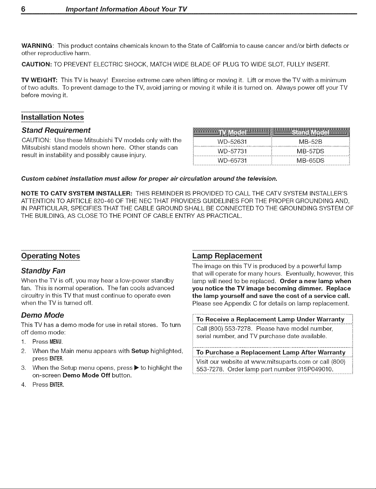
Stand Requirement
CAUTION: Use these Mitsubishi TV models only with the
Mitsubishi stand models shown here. Other stands can
result in instability and possibly cause injury.
Custom cabinet installation must allow for proper air circulation around the television.
NOTE TO CATV SYSTEM INSTALLER: THIS REMINDER IS PROVIDED TO CALL THE CATV SYSTEM INSTALLER'S
ATTENTION TO ARTICLE 820-40 OF THE NEC THAT PROVIDES GUIDELINES FOR THE PROPER GROUNDING AND,
IN PARTICULAR, SPECIFIES THAT THE CABLE GROUND SHALL BE CONNECTED TO THE GROUNDING SYSTEM OF
THE BUILDING, AS CLOSE TO THE POINT OF CABLE ENTRY AS PRACTICAL.
Operating Notes
Standby Fan
When the TV is off, you may hear a low-power standby
fan. This is normal operation. The fan cools advanced
circuitry in this TV that must continue to operate even
when the TV is turned off.
Demo Mode
This TV has a demo mode for use in retail stores. To turn
off demo mode:
1. Press MENU.
2. When the Main menu appears with Setup highlighted,
press ENTER.
3. When the Setup menu opens, press _ to highlight the
on-screen Demo Mode Off button.
4. Press ENTER.
Lamp Replacement
The image on this TV is produced by a powerful lamp
that will operate for many hours. Eventually, however, this
lamp will need to be replaced. Order a new lamp when
you notice the TV image becoming dimmer. Replace
the lamp yourself and save the cost of a service call.
Please see Appendix C for details on lamp replacement.
To Receive a Replacement Lamp Under Warranty
serial number, and TV purchase date available.
553-7278. Order lamp part number 915P049010.
important information About Your TV 7
Cleaning Recommendations
Normally, light dusting with a dry, non-scratching duster
will keep your TV clean. If cleaning beyond this is needed,
please use the following guidelines:
First, turn off the TV and unplug the power cord from the
power outlet.
Top and Sides of the TV
• Gently wipe down your TV with a soft, non-abrasive
cloth such as cotton flannel or a clean cloth diaper,
lightly moistened with water. Dry with a second dry,
soft, non-abrasive cloth.
For oily dirt, add a few drops of mild liquid detergent,
such as dishwashing detergent, to the water used to
moisten the cloth. Rinse with a second cloth moist-
ened only with water. Dry with a third dry, soft, non-
abrasive cloth.
Screen
• Follow the instructions for the top and sides, wiping
gently in an up and down motion, following the
grooves in the screen.
Clean the entire screen evenly, not just sections of the
screen.
Do not allow liquid to drip down the grooves of the
screen, as some liquid may enter the TV through the
gap between the screen and screen frame.
You may purchase Mitsubishi Screen Cleaner, part
number CLEANER-VSS, by calling (800) 553-7278.
TV Software
Unauthorized Software
Do not attempt to update the software of this TV with
software or cards that are not provided by or authorized
by Mitsubishi Digital Electronics America, Inc. Non-autho-
rized software may damage the TV and will not be covered
by the warranty.
Software Updates
From time to time, Mitsubishi may offer software updates
to expand the features or operation of this TV. When
these updates are available they will be announced on our
web site, Mitsubishi-tv.com. If you return your owner's
registration card, with your model and serial number,
you may receive written notification of available software
updates.
General Cleaning Warnings
DO NOT allow liquid to enter the TV through the venti-
lation slots or any crevice.
DO NOT use any strong or abrasive cleaners, as these
can scratch the surfaces.
DO NOT use any cleaners containing ammonia,
bleach, alcohol, benzene, or thinners, as these can
dull the surfaces.
DO NOT spray liquids or cleaners directly on the TV's
surfaces.
DO NOT scrub or rub the TV harshly. Wipe it gently.
___of abrasive cleaner
face of the TV screen.
8 important information About Your TV
Important Safeguards
Please read the following safeguards for your TV and retain for future reference. Always follow all warnings and instruc-
tions marked on the television.
1. Read, Retain and Follow All instructions
Read all safety and operating instructions before operating the TV. Retain the safety and operating instructions
for future reference. Follow all operating and use instructions.
2. Heed Warnings
Adhere to all warnings on the appliance and in the operating instructions.
3. Cleaning
Unplug the TV from the wall outlet before cleaning. Do not use liquid, abrasive or aerosol cleaners. Cleaners
can permanently damage the cabinet and screen. Use a lightly dampened cloth for cleaning.
4. Attachments and Equipment
Never add any attachments and/or equipment without approval of the manufacturer as such additions may
result in the risk of fire, electric shock or other personal injury.
5. Water and Moisture
Do not use the TV where contact with or immersion in water is possible. Do not use near bath tubs, wash
bowls, kitchen sinks, laundry tubs, swimming pools, etc.
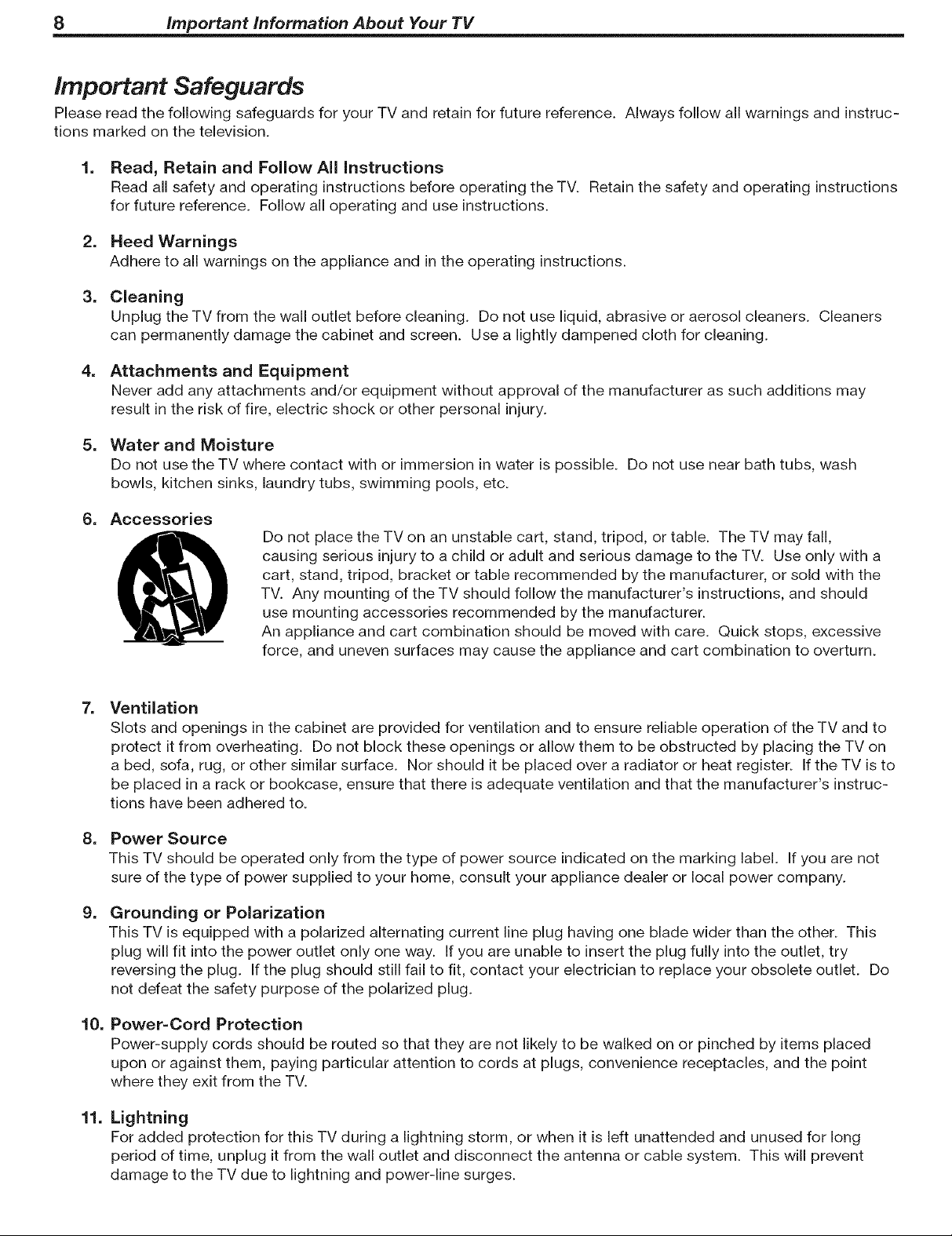
6. Accessories
Do not place the TV on an unstable cart, stand, tripod, or table. The TV may fall,
causing serious injury to a child or adult and serious damage to the TV. Use only with a
cart, stand, tripod, bracket or table recommended by the manufacturer, or sold with the
TV. Any mounting of the TV should follow the manufacturer's instructions, and should
use mounting accessories recommended by the manufacturer.
An appliance and cart combination should be moved with care. Quick stops, excessive
force, and uneven surfaces may cause the appliance and cart combination to overturn.
=
Ventilation
Slots and openings in the cabinet are provided for ventilation and to ensure reliable operation of the TV and to
protect it from overheating. Do not block these openings or allow them to be obstructed by placing the TV on
a bed, sofa, rug, or other similar surface. Nor should it be placed over a radiator or heat register. If the TV is to
be placed in a rack or bookcase, ensure that there is adequate ventilation and that the manufacturer's instruc-
tions have been adhered to.
=
Power Source
This TV should be operated only from the type of power source indicated on the marking label. If you are not
sure of the type of power supplied to your home, consult your appliance dealer or local power company.
g=
Grounding or Polarization
This TV is equipped with a polarized alternating current line plug having one blade wider than the other. This
plug will fit into the power outlet only one way. If you are unable to insert the plug fully into the outlet, try
reversing the plug. If the plug should still fail to fit, contact your electrician to replace your obsolete outlet. Do
not defeat the safety purpose of the polarized plug.
10.
Power=Cord Protection
Power-supply cords should be routed so that they are not likely to be walked on or pinched by items placed
upon or against them, paying particular attention to cords at plugs, convenience receptacles, and the point
where they exit from the TV.
11.
Lightning
For added protection for this TV during a lightning storm, or when it is left unattended and unused for long
period of time, unplug it from the wall outlet and disconnect the antenna or cable system. This will prevent
damage to the TV due to lightning and power-line surges.
Important Safeguards, continued
12. Power Lines
An outside antenna system should not be located in the vicinity of overhead power lines or other electric light or
power circuits, or where it can fall into such power lines or circuits. When installing an outside antenna system,
extreme care should be taken to keep from touching such power lines or circuits as contact with them might be
fatal.
13. OveHoading
Do not overload wall outlets and extension cords as this can result in a risk of fire or electric shock.
14. Object and Liquid Entry
Never push objects of any kind into this TV through openings as they may touch dangerous voltage points or
short-out parts that could result infire or electric shock. Never spill liquid of any kind on or into the TV.
important information About Your TV 9
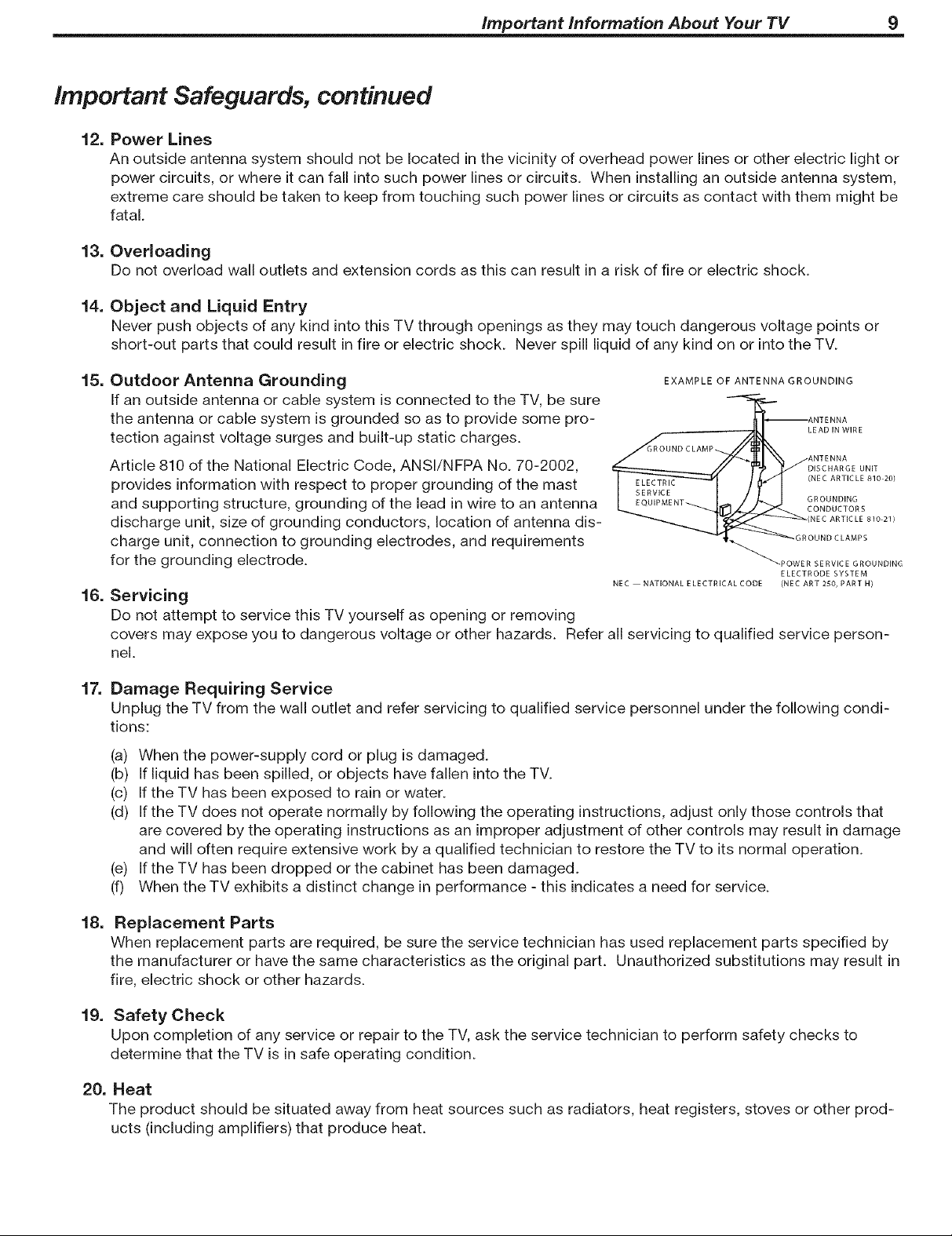
15.
Outdoor Antenna Grounding
EXAMPLE OF ANTENNA GROUNDING
If an outside antenna or cable system is connected to the TV, be sure
the antenna or cable system is grounded so as to provide some pro-
tection against voltage surges and built-up static charges.
Article 810 of the National Electric Code, ANSI/NFPA No. 70-2002,
GROUND CLAMP
LEAD IN WIRE
ANTENNA
ANTENNA
DISCHARGE UNIT
provides information with respect to proper grounding of the mast
and supporting structure, grounding of the lead in wire to an antenna
discharge unit, size of grounding conductors, location of antenna dis-
charge unit, connection to grounding electrodes, and requirements
for the grounding electrode.
16.
Servicing
NEC NATIONAL E LECTRICAL CODE (NEC ART 250, PART H/
GROUNDING
CONDUCTORS
(NEC ARTICLE 810 21)
OUND CLAMPS
(NEC ARTICLE 810 20)
POWER SERVICE GROUNDING
ELECTRODE SYSTEM
Do not attempt to service this TV yourself as opening or removing
covers may expose you to dangerous voltage or other hazards. Refer all servicing to qualified service person-
nel.
17.
Damage Requiring Service
Unplug the TV from the wall outlet and refer servicing to qualified service personnel under the following condi-
tions:
(a) When the power-supply cord or plug is damaged.
(b) If liquid has been spilled, or objects have fallen into the TV.
(c) If the TV has been exposed to rain or water.
(d) If the TV does not operate normally by following the operating instructions, adjust only those controls that
are covered by the operating instructions as an improper adjustment of other controls may result in damage
and will often require extensive work by a qualified technician to restore the TV to its normal operation.
(e) If the TV has been dropped or the cabinet has been damaged.
(f) When the TV exhibits a distinct change in performance - this indicates a need for service.
18.
Replacement Parts
When replacement parts are required, be sure the service technician has used replacement parts specified by
the manufacturer or have the same characteristics as the original part. Unauthorized substitutions may result in
fire, electric shock or other hazards.
19. Safety Check
Upon completion of any service or repair to the TV, ask the service technician to perform safety checks to
determine that the TV is in safe operating condition.
20. Heat
The product should be situated away from heat sources such as radiators, heat registers, stoves or other prod-
ucts (including amplifiers) that produce heat.
Television Overview
Package Contents .................................. 12
Special Features of Your TV ............................ 12
Guidelines for Setting Up and Using Your New Widescreen TV . .. 13
TV Front Panel
Control Panel ..................................... 15
input 3 ......................................... 15
Front-Panel indicators ................................ 16
CabieCARD TM Technology ............................. 17
TV Back Panel ..................................... 18
12 Chapter 1. Television Overview
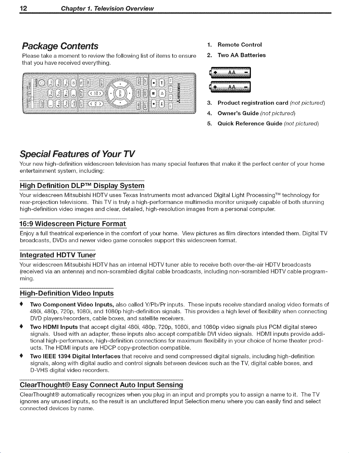
Package Contents
Please take a moment to review the following list of items to ensure
that you have received everything.
1. Remote Control
2. Two AA Batteries
3. Product registration card (not pictured)
4. Owner's Guide (not pictured)
5. Quick Reference Guide (not pictured)
Special Features of Your TV
Your new high-definition widescreen television has many special features that make it the perfect center of your home
entertainment system, including:
High Definition DLP TM Display System
Your widescreen Mitsubishi HDTV uses Texas Instruments most advanced Digital Light Processing TM technology for
rear-projection televisions. This TV is truly a high-performance multimedia monitor uniquely capable of both stunning
high-definition video images and clear, detailed, high-resolution images from a personal computer.
16:9 Widescreen Picture Format
Enjoy a full theatrical experience in the comfort of your home. View pictures as film directors intended them. Digital TV
broadcasts, DVDs and newer video game consoles support this widescreen format.
integrated HDTV Tuner
Your widescreen Mitsubishi HDTV has an internal HDTV tuner able to receive both over-the-air HDTV broadcasts
(received via an antenna) and non-scrambled digital cable broadcasts, including non-scrambled HDTV cable program-
ming.
High=Definition Video inputs
0 Two Component Video Inputs, also called Y/Pb/Pr inputs. These inputs receive standard analog video formats of
480i, 480p, 720p, 1080i, and 1080p high-definition signals. This provides a high level of flexibility when connecting
DVD players/recorders, cable boxes, and satellite receivers.
0 Two HDMI Inputs that accept digital 480i, 480p, 720p, 1080i, and 1080p video signals plus PCM digital stereo
signals. Used with an adapter, these inputs also accept compatible DVl video signals. HDMI inputs provide addi-
tional high-performance, high-definition connections for maximum flexibility in your choice of home theater prod-
ucts. The HDMI inputs are HDCP copy-protection compatible.
0 Two iEEE 1394 Digital interfaces that receive and send compressed digital signals, including high-definition
signals, along with digital audio and control signals between devices such as the TV, digital cable boxes, and
D-VHS digital video recorders.
ClearThought® Easy Connect Auto input Sensing
ClearThought® automatically recognizes when you plug in an input and prompts you to assign a name to it. The TV
ignores any unused inputs, so the result is an uncluttered Input Selection menu where you can easily find and select
connected devices by name.
Chapter 1. Television Overview 13
Digital Cable Ready (CableCARDTM), Models WD=57731 and 65731
Your widescreen Mitsubishi HDTV is "Plug-and-Play" digital cable ready. It can descramble a cable provider's one-way
digital signals with the use of a CableCARD security module. The CableCARD is used in place of a traditional cable box
to access digital cable programming (including high definition). Contact your local cable provider for availability infor-
mation and service details.
Guidelines for Setting Up and Using
Your New Widescreen TV
Getting Started
1.
Read the section entitled "important information
About Your TV" starting on page 5.
2.
Choose a location for your TV. 1.
• Allow at least four inches of space on all sides of
the TV to help prevent overheating.
Avoid locations where light may reflect off the 2.
screen.
See the stand requirements under "Important
information About Your TV."
.
Install the batteries in the remote control. See
chapter 3, "TV Operation," for information on use
and care of the remote control.
4.
Plug your TV into a power outlet. The POWERindicator
on the front of the TV will start blinking rapidly. After
the POWERindicator stops blinking, press the POWERkey
to power on the TV.
5.
When the Welcome screen appears the first time you
power on the TV, select a language for TV menus.
You can later change the language through the Setup
menu.
.
Some TVs are shipped from the factory with demo
mode active for use in retail stores. If demo mode is
active when you first turn on the TV:
a. Press MENU.
b. When the Main menu appears with Setup high-
lighted, press ENTER.
c. When the Setup menu opens, press I_ to highlight
the on-screen Demo Mode Off button.
d. Press ENTER.
7. Connect your other A/V devices to the TV and assign
device names to the TV inputs when prompted.
See chapter 2, "TV Connections," for connection
diagrams. You can reassign device names later if
needed. See "input Name Menu" in chapter 4, "TV
Menu Settings."
8. Memorize channels if you plan to watch over-the-air
channels or programming over direct cable. Channel
memorization may take up to 15 minutes to complete.
See "Setup Menu" in chapter 4, "TV Menu Set=
tings,"
g.
You can now start watching TV or you can perform
additional setup and customization through the TV
menus.
Additional TV Setup
To program the remote control to operate your other
A/V devices, see chapter 5, "Operating Other
Devices with the Remote Control."
Review chapter 4, "TV Menu Settings," to custom-
ize TV operation. Press the MENUkey to enter the menu
system. Some examples of settings you may wish to
change include:
Energy Mode. For faster power-on, keep the
Energy Mode set to Fast Power On. For lower
power consumption while the TV is off, use the
Low Power setting. See "Setup Menu."
Input Name. Change the device names that
appear in the Input Selection menu. See "Input
Name Menu."
= Icon Order. Rearrange the device icons in the
Input Selection menu to put frequently used icons
near the front. See "Icon Order Menu."
• FAV. Create lists of your favorite channels so you
can find them quickly. See "Channel Menu."
= Clock. If you wish to schedule future recordings
or use the Timer feature to have the TV come on
automatically, you must first set the TV clock to
the correct time. See "Setup Menu."
Parental Lock. You can restrict TV viewing by
program rating or by time of day. You can also
disable the front-panel buttons--useful if you have
small children. See "Parental Lock Menu."
Video Settings. Change the video adjustments
to get the best picture for your viewing conditions.
See "Audio/Video Menu."
You may wish to change the Picture Mode from
the default Brilliant to either Bright or Natural,
which are suitable for most home viewing environ-
ments.
.
If you have IEEE 1394 A/V devices, see chapter 7,
"Using IEEE 1394 Devices," for details on operating
such devices and using the TV to control recording.
14 Chapter 1. Television Overview
Guidelines for Setting Up and Using
Your New Widescreen TV, continued
TV Operation
Review chapter 3, "TV Operation," for TV features
including:
• Input Selection (viewing source). Select a con-
nected program source to watch, such as a VCR,
DVD player, or antenna. Press INPUTon the remote
control to select from icons for the TV inputs. See
"input Selection Menu."
• Channel Listings. Press GUIDEto view
ChannelView TM channel listings. See
"ChannelView TM Channel Guide."
Picture Formats. Press FORMATto cycle through
the available picture sizes and shapes to find the
one best suited to the program you're watching.
See "TV Signals and Display Formats."
• SPLIT. Press SPLITto view two programs at the
same time. See "Split Screen Mode."
TV Care
Caring for your TV:
Lamp Cartridge. When the lamp cartridge needs
replacement, replace the lamp yourself and
save the cost of a service call. See Appendix
C for instructions.
General Cleaning. To keep your TV looking its
best, see the cleaning recommendations under
"Important information About Your TV."
Assistance
If you need assistance with this TV:
For troubleshooting, service, and product support,
see Appendix D.
For warranty information, see the TV warranty in
the back of this book.
TV Front Panel
s
\
Chapter 1. Television Overview 15
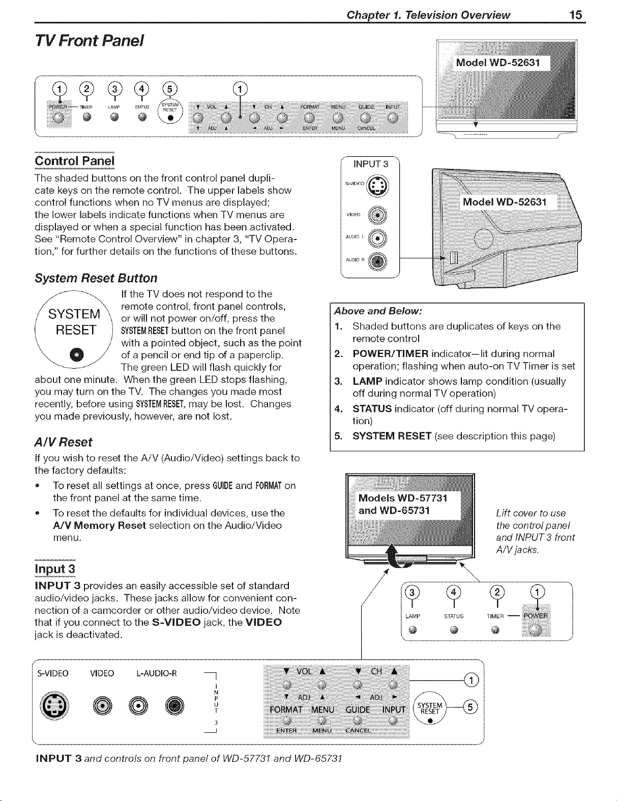
Control Panel
The shaded buttons on the front control panel dupli-
cate keys on the remote control. The upper labels show
control functions when no TV menus are displayed;
the lower labels indicate functions when TV menus are
displayed or when a special function has been activated.
See "Remote Control Overview" in chapter 3, "TV Opera-
tion," for further details on the functions of these buttons.
System Reset Button
If the TV does not respond to the
remote control, front panel controls,
or will not power on/off, press the
SYSTEMRESETbutton on the front panel
with a pointed object, such as the point
of a pencil or end tip of a paperclip.
The green LED will flash quickly for
about one minute. When the green LED stops flashing,
you may turn on the TV. The changes you made most
recently, before using SYSTEMRESET,may be lost. Changes
you made previously, however, are not lost.
A/V Reset
If you wish to reset the A!V (Audio/Video) settings back to
the factory defaults:
• To reset all settings at once, press GUIDEand FORMATon
the front panel at the same time.
To reset the defaults for individual devices, use the
A/V Memory Reset selection on the Audio/Video
menu.
iNPUT 3
;-VIDEO @
VIDE() @
Above and Below:
1. Shaded buttons are duplicates of keys on the
remote control
2. POWER/TIMER indicator--lit during normal
operation; flashing when auto-on TV Timer is set
3. LAMP indicator shows lamp condition (usually
off during normal TV operation)
4. STATUS indicator (off during normal TV opera-
tion)
5. SYSTEM RESET (see description this page)
Lift cover to use
the control panel
and INPUT3 front
A/V jacks.
input 3
iNPUT 3 provides an easily accessible set of standard
audio/video jacks. These jacks allow for convenient con-
nection of a camcorder or other audio/video device. Note
that if you connect to the S=VIDEO jack, the VIDEO
jack is deactivated.
VIDEO
@
iNPUT 3 and controls on front panel of WD-57731 and WD-65731
L-AUDIO-R
@
I
N
P
U
T
3
I_ STATUES
@
16 Chapter 1. Television Overview
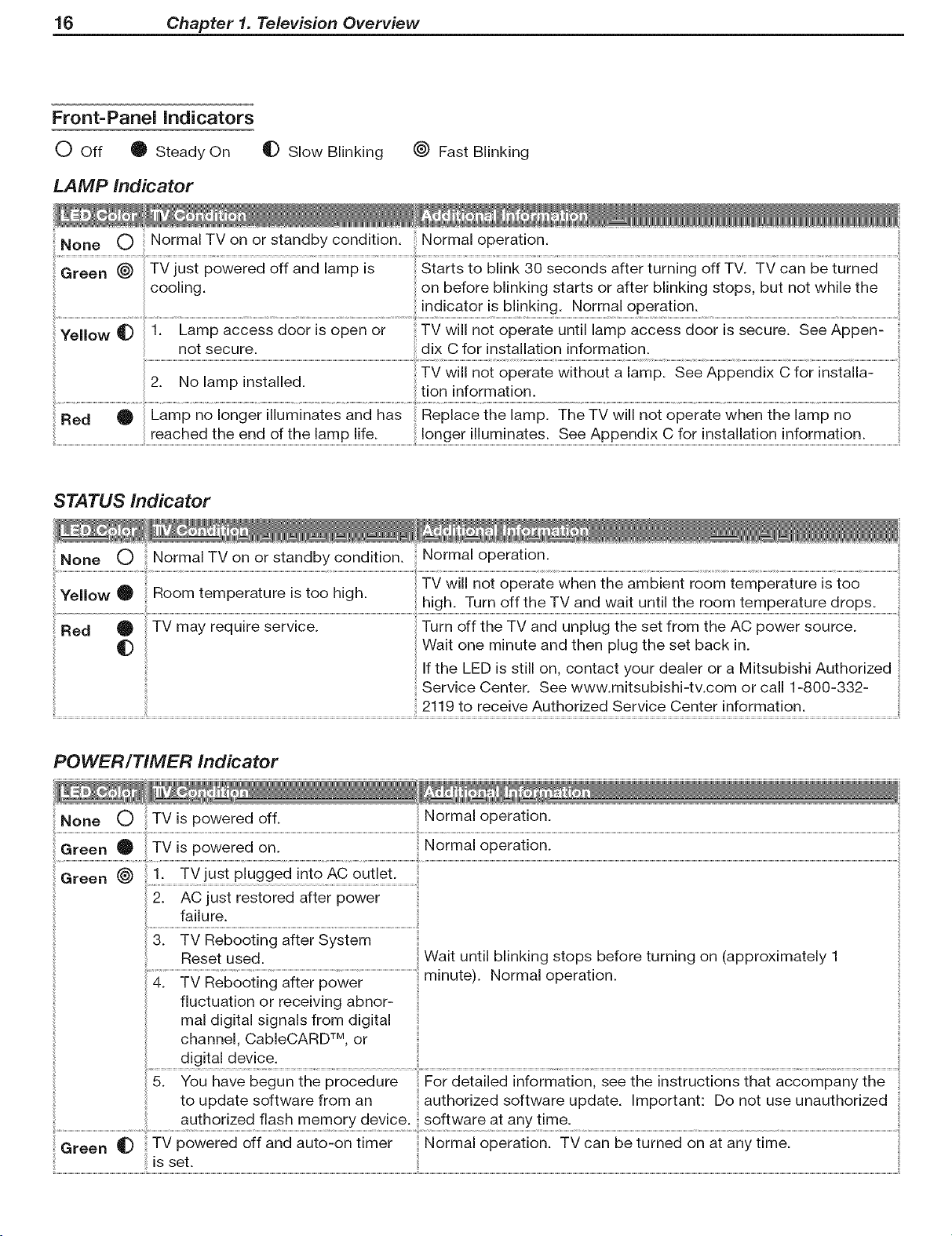
Front=Panel indicators
O Off O Steady On
qD Slow Blinking (_ Fast Blinking
LAMP Indicator
Green _ TV just powered off and lamp is Starts to blink 30 seconds after turning off TV. TV can be turned
cooling, on before blinking starts or after blinking stops, but not while the
indicator is blinking. Normal operation.
Ye"ow_ i: Eampac_es_doo;isopenoi.........T_wiiinoiop_;aieuni"ia_pac_ssdo_;issecuie:Se_Appen:
not secure, dix C for installation information.
2. No namp nnstalleu. ...... "
.................................................................................................reached!h endo!!h !am#!!!e:.........................................!onge!um!Pa!e SeA#Pend! C1o!np!a!!a!!£!P[trma!!£.....................................
STATUS Indicator
None O Normal TV on or standby condition. Normal operation.
Yellow O _oom temperature s too n gn
Red _ TV may require service. Turn off the TV and unplug the set from the AC power source.
_D Wait one minute and then plug the set back in.
, , TV w not operate when the amb ent room temperature s too
_lon ,n_orma[_on.
hugh. Turn off the TV and want until the room temperature drops. :_
If the LED is still on, contact your dealer or a Mitsubishi Authorized
Service Center. See www.mitsubishi-tv.com or call 1-800-332-
2119 to receive Authorized Service Center information.
POWER/TIMER Indicator
Green _)
1. TVjust plugged into AC outlet.
restored after power ........................................
failure.
Reset used.
4. TV Rebooting after power
fluctuation or receiving abnor-
mal digital signals from digital
channel, CableCARD TM, or
.............................digital device _
5. You have begun the procedure For detailed information, see the instructions that accompany the
to update software from an authorized software update. Important: Do not use unauthorized
authorized flash memory device, software at any time.
Wait until blinking stops before turning on (approximately 1
minute). Normal operation.
CableCARD TM Technology
(models WD=57731 and WD-65731)
CableCARD is a nationwide system standard that allows
your local cable TV provider to supply you with an access
card customized to your account. This card allows your
TV to receive, decode, and unscramble the premium
digital channels included in your cable TV subscription
without the use of a cable box. When you move to a
new cable provider's area, return the CableCARD to the
original cable provider and get a new card from your new
provider.
Please note that CableCARD is a relatively new technology
and your local cable provider may not currently be offer-
ing this service. As time passes, this system will become
broadly supported by most cable providers.
The CableCARD system is unidirectional, meaning your
cable provider can send updates to the TV, but the TV
cannot send signals back. As a result, certain advanced
and interactive digital cable services, such as requests for
video-on-demand and pay-per-view programs, a cable
operator's enhanced program guide, and data-enhanced
television services may require use of a set-top box
instead. For more information, call your local cable opera-
tor.
Digital cable channels authorized by the CableCARD are
available on the Firewire® IEEE 1394 network and can be
shared by other products on the network. You may be
unable to record or copy some digital programs, however,
because of copy restrictions set by the content or copy-
right owners.
Chapter 1. Television Overview 17
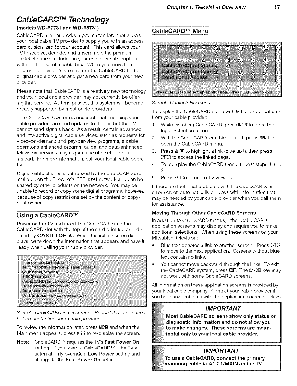
CabieCARD TM Menu
Sample CableCARD menu
To display the CableCARD menu with links to applications
from your cable provider:
1. While watching CableCARD, press INPUTto open the
Input Selection menu.
2. With the CableCARD icon highlighted, press MENUto
open the CableCARD menu.
3. Press A Y to highlight a link (blue text), then press
ENTERto access the linked page.
4. To redisplay the CableCARD menu, repeat steps 1 and
2.
5. Press EXITto return to TV viewing.
If there are technical problems with the CableCARD, an
error screen automatically displays with information that
may be needed by your cable provider when you call them
for assistance.
Using a CabieCARD TM
Power on the TV and insert the CabieCARD into the
CableCARD slot with the top of the card oriented as indi-
cated by CARD TOP A. When the initial screen dis-
plays, write down the information that appears and have it
ready when calling your cable provider.
Sample CableCARD initial screen. Record the information
before contacting your cable provider.
To review the information later, press MENUand when the
Main menu appears, press 9 99to re-display the screen.
Note: CableCARD TM requires the TV's Fast Power On
setting. If you insert a CableCARD TM, the TV will
automatically override a Low Power setting and
change to the Fast Power On setting.
Moving Through Other CableCARD Screens
In addition to CableCARD menus, other CableCARD
application screens may display and require you to make
additional selections. When using these screens on your
Mitsubishi television:
• Blue text denotes a link to another screen. Press ENTER
to move to the next application. Screens without blue
text contain no links.
You cannot move backward through the links. To exit
the CableCARD system, press EXIT.The CANCELkey may
not work with some CableCARD screens.
All information on these application screens is provided by
your local cable company. Contact your cable provider if
you have any problems with the application screen displays.
18 Chapter 1. Television Overview
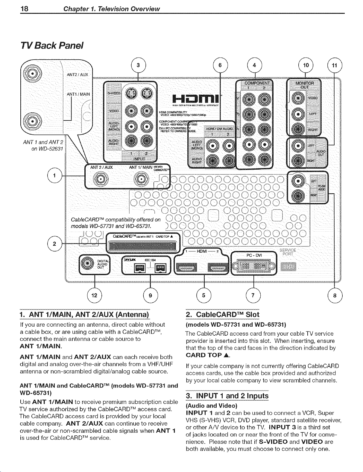
TV Back Panel
ANT2 / AUX
H :3m|
ANT 1
on WD-52631
ANT1 I MAIN
@@
/
ANT 1/MAIN
HDMI COMPATIBILITY
VIDEO: 480V480c 720cJ1080i/1 OS0c
1. ANT l/MAIN, ANT 2/AUX (Antenna)
If you are connecting an antenna, direct cable without
a cable box, or are using cable with a CableCARD TM,
connect the main antenna or cable source to
ANT l/MAIN.
ANT 1/iVlAIN and ANT 2/AUX can each receive both
digital and analog over-the-air channels from a VHF/UHF
antenna or non-scrambled digital/analog cable source.
ANT l/MAIN and CableCARD TM (models WD=57731 and
WD-65731)
Use ANT l/MAIN to receive premium subscription cable
TV service authorized by the CableCARD TM access card.
The CableCARD access card is provided by your local
cable company. ANT 2/AUX can continue to receive
over-the-air or non-scrambled cable signals when ANT 1
is used for CableCARD TM service.
2. CabieCARD TM Slot
(models WD=57731 and WD=65731)
The CableCARD access card from your cable TV service
provider is inserted into this slot. When inserting, ensure
that the top of the card faces in the direction indicated by
CARD TOP A.
If your cable company is not currently offering CableCARD
access cards, use the cable box provided and authorized
by your local cable company to view scrambled channels.
3. iNPUT 1 and 2 inputs
(Audio and Video)
iNPUT 1 and 2 can be used to connect a VCR, Super
VHS (S-VHS) VCR, DVD player, standard satellite receiver,
or other A/V device to the TV. INPUT 3 isa third set
of jacks located on or near the front of the TV for conve-
nience. Please note that if S=VIDEO and VIDEO are
both available, you must choose to connect only one.
Chapter 1. Television Overview 19
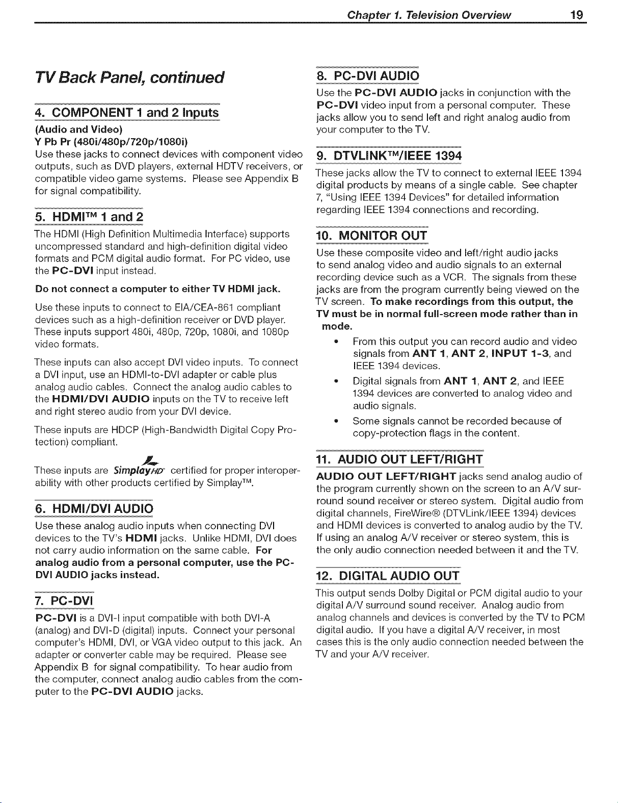
TV Back Panel, continued
4. COMPONENT 1 and 2 inputs
(Audio and Video)
Y Pb Pr (480i/480p/720p/1080i)
Use these jacks to connect devices with component video
outputs, such as DVD players, external HDTV receivers, or
compatible video game systems. Please see Appendix B
for signal compatibility.
5. HDMF M 1 and 2
The HDMI (High Definition Multimedia Interface) supports
uncompressed standard and high-definition digital video
formats and PCM digital audio format. For PC video, use
the PC=DVl input instead.
Do not connect a computer to either TV HDMI jack.
Use these inputs to connect to EIA/CEA-861 compliant
devices such as a high-definition receiver or DVD player.
These inputs support 480i, 480p, 720p, 1080i, and 1080p
video formats.
These inputs can also accept DVl video inputs. To connect
a DVl input, use an HDMI-to-DVl adapter or cable plus
analog audio cables. Connect the analog audio cables to
the HDMI/DVl AUDIO inputs on the TV to receive left
and right stereo audio from your DVl device.
These inputs are HDCP (High-Bandwidth Digital Copy Pro-
tection compliant.
These inputs are ._implay/-/D certified for proper interoper-
ability with other products certified by Simplay TM.
6. HDMI/DVl AUDIO
Use these analog audio inputs when connecting DVI
devices to the TV's HDMI jacks. Unlike HDMI, DVl does
not carry audio information on the same cable. For
analog audio from a personal computer, use the PC=
DVl AUDIO jacks instead.
7. PC=DVI
PC=DVI is a DVI-I input compatible with both DVI-A
(analog) and DVI-D (digital) inputs. Connect your personal
computer's HDMI, DVI, or VGA video output to this jack. An
adapter or converter cable may be required. Please see
Appendix B for signal compatibility. To hear audio from
the computer, connect analog audio cables from the com-
puter to the PO=DVl AUDIO jacks.
8. PC=DVI AUDIO
Use the PC=DVI AUDIO jacks in conjunction with the
PC=DVl video input from a personal computer. These
jacks allow you to send left and right analog audio from
your computer to the TV.
9. DTVLINKTM/IEEE 1394
These jacks allow the TV to connect to external IEEE 1394
digital products by means of a single cable. See chapter
7, "Using IEEE 1394 Devices" for detailed information
regarding IEEE 1394 connections and recording.
10. MONITOR OUT
Use these composite video and left/right audio jacks
to send analog video and audio signals to an external
recording device such as a VCR. The signals from these
jacks are from the program currently being viewed on the
TV screen. To make recordings from this output, the
TV must be in normal full=screen mode rather than in
mode.
= From this output you can record audio and video
signals from ANT 1, ANT 2, iNPUT 1=3, and
IEEE 1394 devices.
• Digital signals from ANT 1, ANT 2, and IEEE
1394 devices are converted to analog video and
audio signals.
Some signals cannot be recorded because of
copy-protection flags in the content.
11. AUDIO OUT LEFT/RIGHT
AUDIO OUT LEFT/RIGHT jacks send analog audio of
the program currently shown on the screen to an A/V sur-
round sound receiver or stereo system. Digital audio from
digital channels, FireWire® (DTVLink/IEEE 1394) devices
and HDMI devices is converted to analog audio by the TV.
If using an analog A/V receiver or stereo system, this is
the only audio connection needed between it and the TV.
12. DiGiTAL AUDIO OUT
This output sends Dolby Digital or PCM digital audio to your
digital A/V surround sound receiver. Analog audio from
analog channels and devices is converted by the TV to PCM
digital audio. If you have a digital A/V receiver, in most
cases this is the only audio connection needed between the
TV and your A/V receiver.
TV Connections
Before You Begin
Choosing a Language for Menus .......................... 22
ClearThought® Easy Connect Auto input Sensing ............... 22
Digital Video and Home Recording ........................ 23
Connection Types ................................... 24
HDTV Cable Box or Satellite Receiver with Component Video .... 25
Standard Cable Box, Satellite Receiver, or Other Device with
S=Video .......................................... 25
Wall Outlet Cable (no cable box) .......................... 26
Antenna with a Single Lead ............................ 27
Antennas with Separate UHF and VHF Leads ................ 27
VCR to an Antenna or Wall Outlet Cable ................... 28
VCR to a Cable Box (Audio & Video) ...................... 29
HDMI Device (Cable Box, Satellite Receiver, DVD Player, or
Other Device) ......................................... 30
DVl Video Device (Cable Box, Satellite Receiver, DVD Player,
or Other Device) .................................... 30
DVD Player with Component Video ....................... 31
A/V Receiver (Stereo System) .......................... 31
Older Cable Box .................................... 32
Camcorder ........................................ 32
22 Chapter 2. TV Connections
Before You Begin
Choosing a Language for Menus
When you power on the TV for the first time, you can
select either English or Spanish for all menus. You can
later change the language through the Setup menu.
3_
Press EXITto close the screen. If you connected
several devices at the same time, the screen for the
next connection will open.
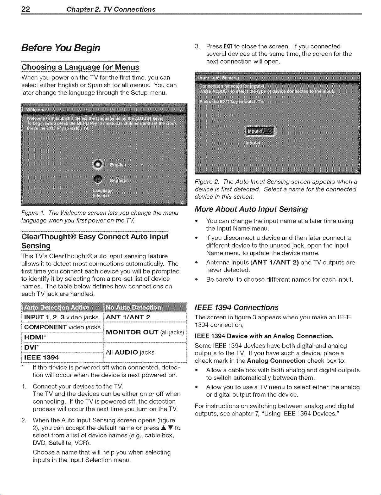
Figure 2. The Auto Input Sensing screen appears when a
device is first detected. Select a name for the connected
device in this screen.
Figure 1. The Welcome screen lets you change the menu
language when you first power on the TV.
ClearThought® Easy Connect Auto input
Sensing
This TV's ClearThought® auto input sensing feature
allows it to detect most connections automatically. The
first time you connect each device you will be prompted
to identify it by selecting from a pre-set list of device
names. The table below defines how connections on
each TV jack are handled.
INPUT 1, 2, 3 video jacks ANT l/ANT 2
......................................................................................................................................................................................................MONITOR OUT (alljaCKS)
IEEE 1394
* If the device is powered off when connected, detec-
tion will occur when the device is next powered on.
Connect your devices to the TV.
The TV and the devices can be either on or off when
connecting. Ifthe TV is powered off, the detection
process will occur the next time you turn on the TV.
When the Auto Input Sensing screen opens (figure
2), you can accept the default name or press A Y to
select from a list of device names (e.g., cable box,
DVD, Satellite, VCR).
Choose a name that will help you when selecting
inputs in the Input Selection menu.
More About Auto Input Sensing
• You can change the input name at a later time using
the Input Name menu.
• If you disconnect a device and then later connect a
different device to the unused jack, open the Input
Name menu to update the device name.
• Antenna inputs (ANT l/ANT 2) and TV outputs are
never detected.
• Be careful to choose different names for each input.
IEEE 1394 Connections
The screen in figure 3 appears when you make an IEEE
1394 connection,
iEEE 1394 Device with an Analog Connection.
Some IEEE 1394 devices have both digital and analog
outputs to the TV. If you have such a device, place a
check mark in the Analog Connection check box to:
• Allow a cable box with both analog and digital outputs
to switch automatically between them.
• Allow you to use a TV menu to select either the analog
or digital output from the device.
For instructions on switching between analog and digital
outputs, see chapter 7, "Using IEEE 1394 Devices."
Chapter 2. TV Connections 23
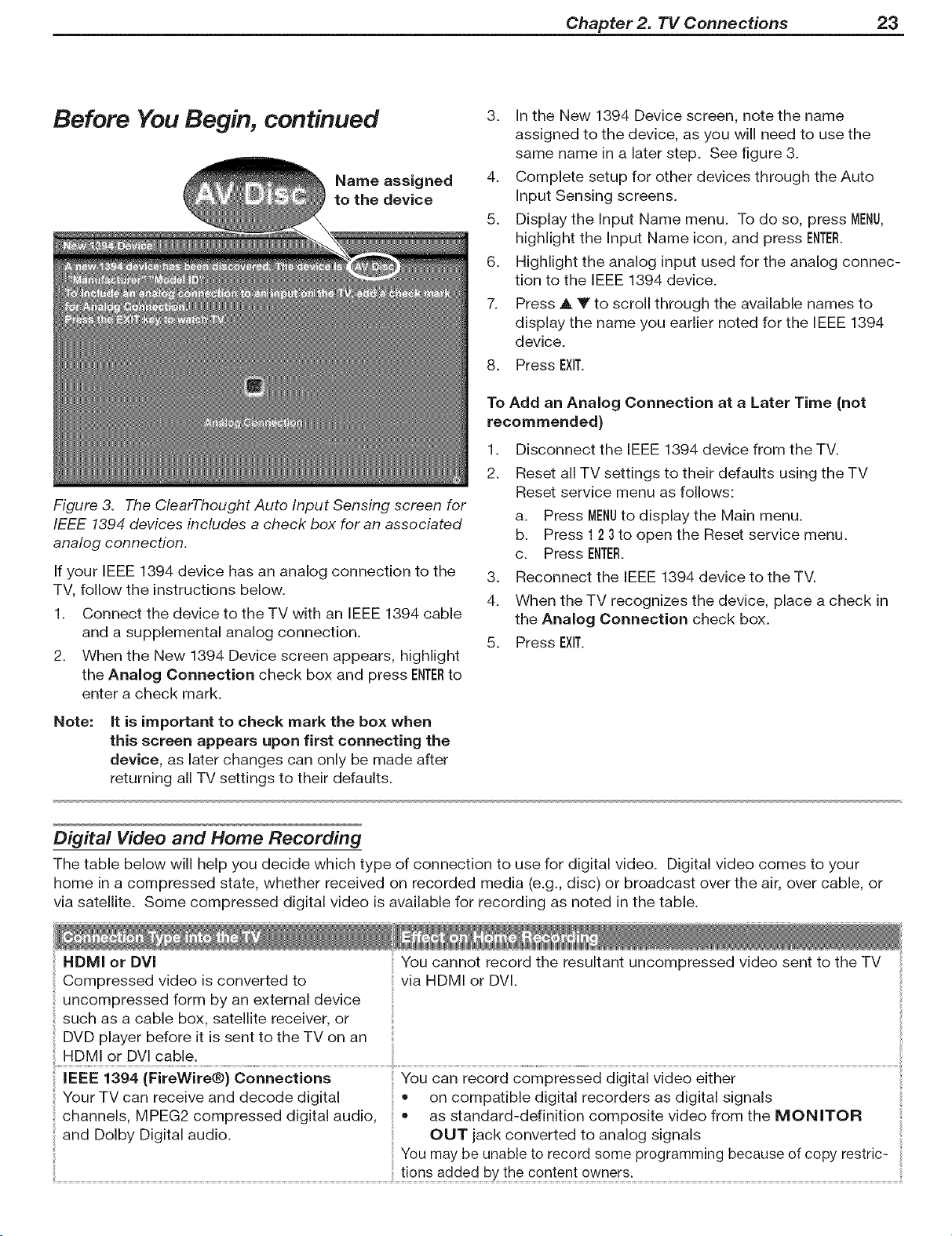
Before You Begin, continued
Name assigned
to the device
Figure 3. The ClearThought Auto Input Sensing screen for
IEEE 1394 devices includes a check box for an associated
analog connection.
If your IEEE 1394 device has an analog connection to the
TV, follow the instructions below.
1. Connect the device to the TV with an IEEE 1394 cable
and a supplemental analog connection.
2. When the New 1394 Device screen appears, highlight
the Analog Connection check box and press ENTERto
enter a check mark.
3. In the New 1394 Device screen, note the name
assigned to the device, as you will need to use the
same name in a later step. See figure 3.
4. Complete setup for other devices through the Auto
Input Sensing screens.
5. Display the Input Name menu. To do so, press MENU,
highlight the Input Name icon, and press ENTER.
6. Highlight the analog input used for the analog connec-
tion to the IEEE 1394 device.
7. Press A Y to scroll through the available names to
display the name you earlier noted for the IEEE 1394
device.
8. Press EXIT.
To Add an Analog Connection at a Later Time (not
recommended)
1. Disconnect the IEEE 1394 device from the TV.
2. Reset all TV settings to their defaults using the TV
Reset service menu as follows:
a. Press MENUto display the Main menu.
b. Press 1 23to open the Reset service menu.
c. Press ENTER.
3. Reconnect the IEEE 1394 device to the TV.
4. When the TV recognizes the device, place a check in
the Analog Connection check box.
5. Press EXIT.
Note: it is important to check mark the box when
this screen appears upon first connecting the
device, as later changes can only be made after
returning all TV settings to their defaults.
Digflal Video and Home Recording
The table below will help you decide which type of connection to use for digital video. Digital video comes to your
home in a compressed state, whether received on recorded media (e.g., disc) or broadcast over the air, over cable, or
via satellite. Some compressed digital video is available for recording as noted in the table.
HDMI or DVl You cannot record the resultant uncompressed video sent to the TV
Compressed video is converted to via HDMI or DVl.
uncompressed form by an external device
such as a cable box, satellite receiver, or
DVD player before it is sent to the TV on an
HDMI or DVl cable.
IEEE 1394 (FireWire®} Connections You can record compressed digital video either
Your TV can receive and decode digital • on compatible digital recorders as digital signals
channels, MPEG2 compressed digital audio, • as standard-definition composite video from the MONITOR
and Dolby Digital audio. OUT jack converted to analog signals
You may be unable to record some programming because of copy restric-
24 Chapter 2. 71/Connections
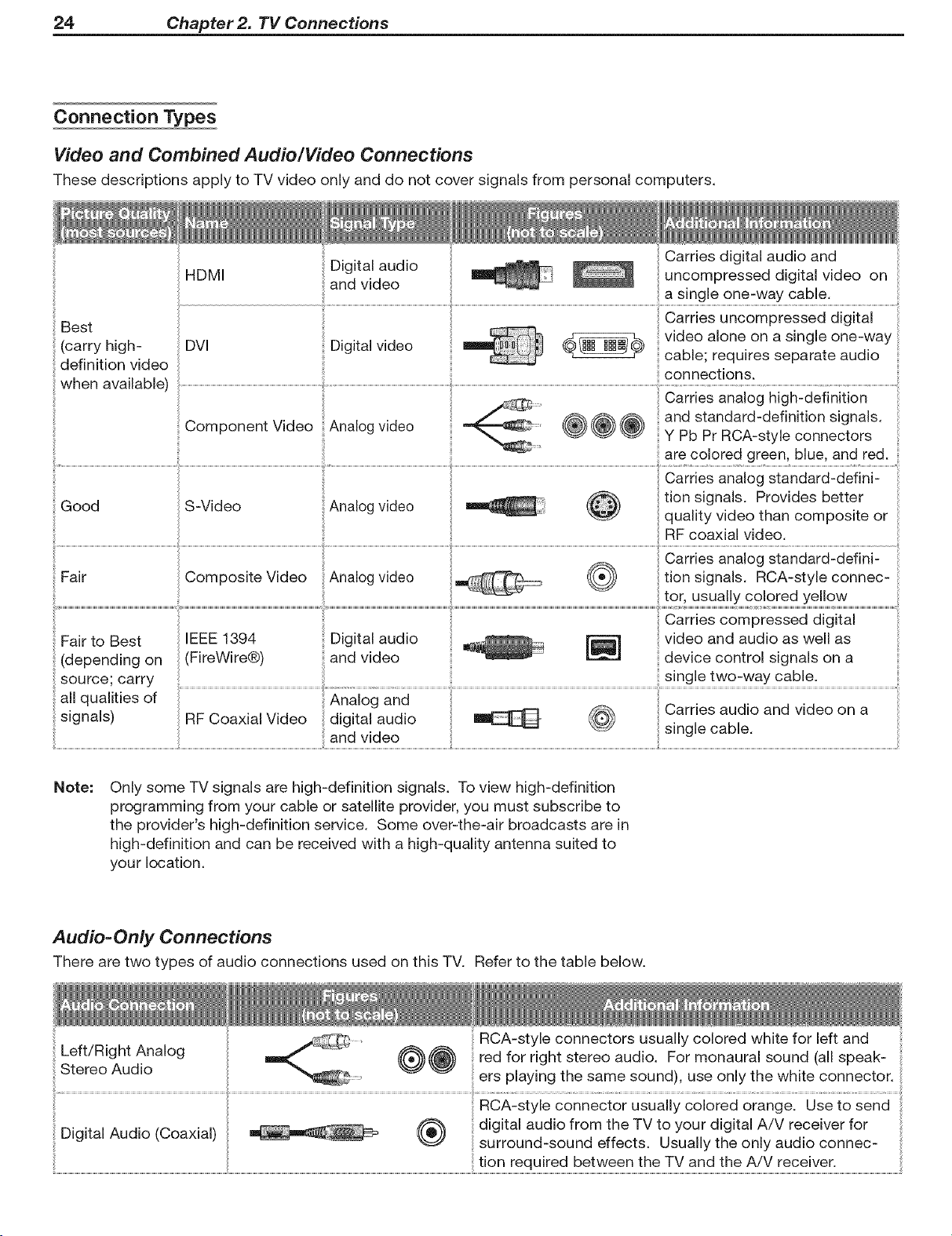
Connection Types
Video and Combined Audio/Video Connections
These descriptions apply to TV video only and do not cover signals from personal computers.
Digital audio
and video
Digital video
Carries uncompressed digital
video alone on a single one-wa_
cable; requires separate audio
connections.
Best
(carry high-
definition video
when available)
HDMI
DVl
Carries analog high-definition
and standard-definition signals.
Component Video Analog video @@@ Y Pb Pr ROA-style connectors
are colored green, blue, and red.
Good S-V u_u ,_._ uu vu_u "
.___ ^ .... ._^^ _ _ t on s gna s Prov des better
...... _ quality video than composite or
RF coaxial video.
Fair to Best IEEE 1394 Digital audio [_ video and audio as well as
(depending on (FireWire®) and video device control signals on a
source; carry single two-way cable.
all qualities of fig and ...........................................................................i.............................................i.........................i........................................................................................
• , , ,, , , , , _ _ _Jarres aug o and v (::leo on a
signals) RF Coaxial vlueo digital audio _ _ . _
; single CaDle,
and video
Note:
Only some TV signals are high-definition signals. To view high-definition
programming from your cable or satellite provider, you must subscribe to
the provider's high-definition service. Some over-the-air broadcasts are in
high-definition and can be received with a high-quality antenna suited to
your location.
Audio=Only Connections
There are two types of audio connections used on this TV. Refer to the table below.
Left/Right Analog
Stereo Audio ers playing the same sound), use only the white connector.
i
........ _ digital audio from the TV to your digital A/V receiver for
LJIglIal _ualo [L,oaxla U _
RCA-style connectors usually colored white for left and
red for right stereo audio. For monaural sound (all speak-
RCA-style connector usually colored oiangel use to send
surround-sound effects. Usually the only audio connec-
i
Chapter 2. TV Connections 25
HDTV Cable Box or Satellite
Receiver with Component Video
If your cable box or satellite receiver has HDMI or DVI
outputs, use the connections for HDMI or DVI video
devices described later in this chapter.
Required: RCA component video cables, left/right
analog audio cables.
A coaxial splitter, available at most electronic supply
stores, may be required to complete this installation.
Connect the cable from the outside cable or satel-
lite service to CABLE iN or SATELLITE iN on
the cable box or satellite receiver. See your device's
owner's guide for instructions and cable compatibility.
SATELLITE iN
To
receiver t.
trial antenna or cable service (not satellite) to ANT
l/MAIN on the TV back panel. A coaxial splitter,
available at most electronics supply stores, may be
required to complete this installation.
Note: To receive the benefits of digital surround sound, con-
nect the digital audio output from your cable box or
satellite receiver directly to your digital A/V receiver.
Standard Cable Box, Satellite
Receiver, or Other Device with
S=Video
Required: S-Video cable and left/right analog stereo
audio cables.
1. Connect the cable from the outside cable or satellite
service to CABLE iN or SATELLITE IN on the
cable box or satellite receiver.
2. Connect an S-Video cable from VIDEO OUT on the
cable box or satellite receiver back panel to INPUT
S=VIDEO on the TV back panel.
3. Connect left (white) and right (red) audio cables from
AUDIO OUT on the cable box or satellite receiver to
INPUT/AUDIO LEFT and AUDIO RIGHT on the
TV back panel.
Note: Refer to the cable box or satellite receiver Owner's
Guide for cable or dish antenna connections to the
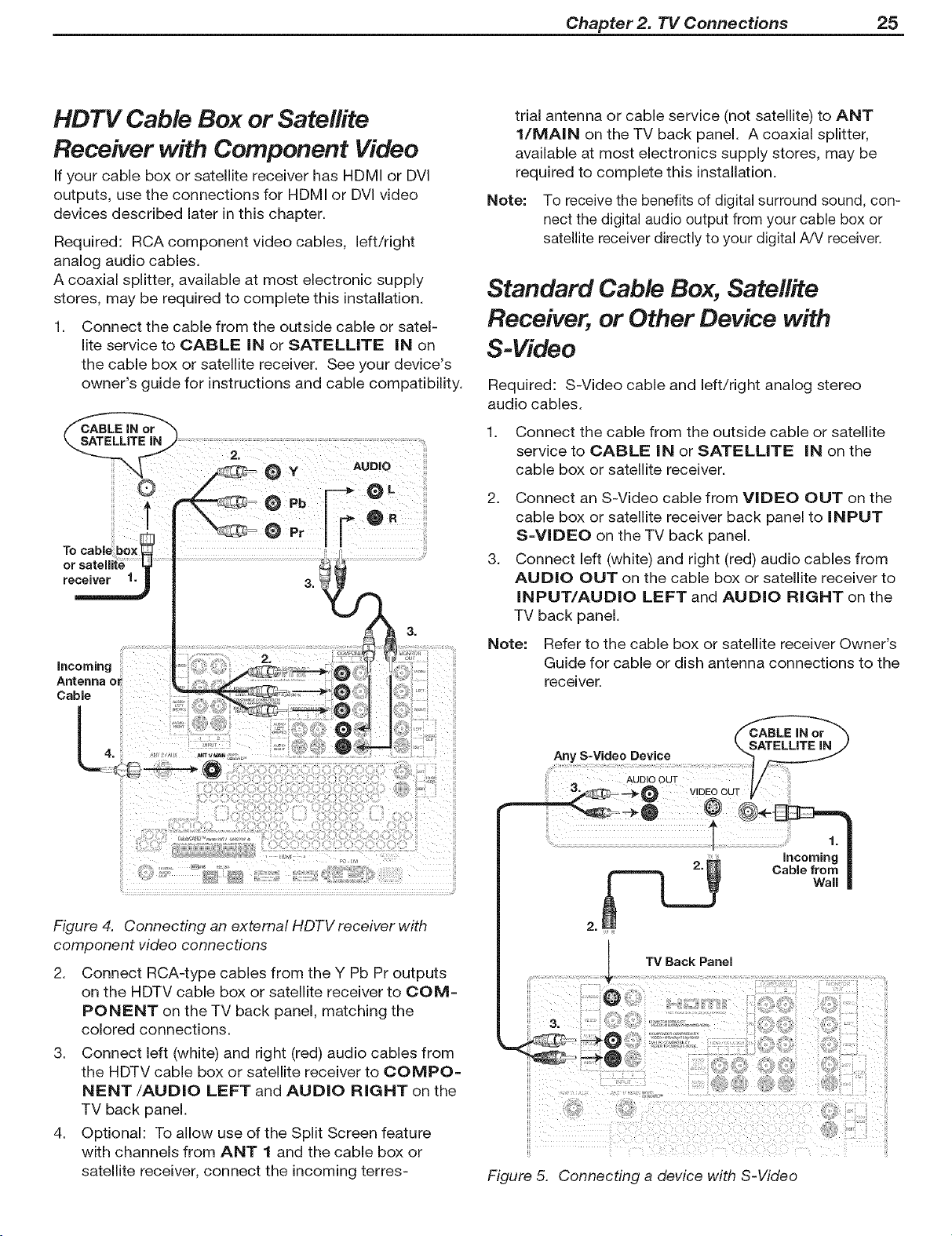
receiver.
Figure 4. Connecting an external HDTV receiver with
component video connections
2. Connect RCA-type cables from the Y Pb Pr outputs
on the HDTV cable box or satellite receiver to COM=
PONENT on the TV back panel, matching the
colored connections.
3. Connect left (white) and right (red) audio cables from
the HDTV cable box or satellite receiver to COMPO=
NENT/AUDIO LEFT and AUDIO RIGHT on the
TV back panel.
4. Optional: To allow use of the Split Screen feature
with channels from ANT 1 and the cable box or
satellite receiver, connect the incoming terres-
!i¸
Jill: I¸¸ i_i_ii!!iii!ii:!¸¸I/:¸¸iiii_iiii!!iii _! ilili
Figure 5. Connecting a device with S-Video
26 Chapter 2. TV Connections
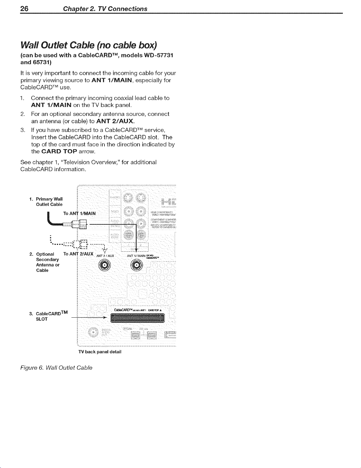
Wall Outlet Cable (no cable box)
(can be used with a CableCARD TM, models WD=57731
and 65731)
It is very important to connect the incoming cable for your
primary viewing source to ANT 1/MA|N, especially for
CableCARD TM use.
1. Connect the primary incoming coaxial lead cable to
ANT 1/MA|N on the TV back panel.
2. For an optional secondary antenna source, connect
an antenna (or cable) to ANT 2/AUX.
3. If you have subscribed to a CableCARD TM service,
Insert the CableCARD into the CableCARD slot. The
top of the card must face in the direction indicated by
the CARD TOP arrow.
See chapter 1, "Television Overview," for additional
CableCARD information.
1. Primary Wall
Outlet Cable
To ANT I/MAIN
=== i=
2. Optional To ANT 2/AUX
Secondary
Antenna or
Cable
3. CableCARD TM
SLOT
TV back panel detail
Figure 6. Wall Outlet Cable
l ...............
ANT 2/AUX ANT 1/MAIN _¢_13 _
CaI_AP, DTM _ _r • C._RDTOPA

Chapter 2. TV Connections 27
Antenna with a Single Lead
A. For an antenna with fiat twin leads
A 300-ohm-to-75-ohm transformer is required, This is not
included with the TV, but is available at most electronics
stores.
A1. For an antenna with flat twin leads, connect the 300-
ohm twin leads to the 300-ohm-to-75-ohm trans-
former.
A2. Push the 75-ohm side of the transformer onto ANT 1
on the TV back panel.
B. For cable or antenna with coaxial lead
Connect the coaxial lead directly to ANT 1 on the TV
back panel,
Antennas with Separate UHF and
VHF Leads
Required: UHF/VHF combiner
This is not included with the TV, but is available at most
electronics stores,
1, Connect the UHF and VHF antenna leads to the UHF/
VHF combiner,
2, Push the combiner onto ANT 1/MA|N on the TV
back panel,
VHF Antenna UHF Antenna
(Channels 2-13) (Channels 14-69)
-- Fiat Twin Lead_
External
Antenna
or Cable
ANT 1/MAI[_ i
Optional 300-Ohm-
to-75-Ohm
Matching Transformer
Figure Z Connecting a Single Antenna
[ 3%°o%t°-
ornbiner 2,
i Baek Side
View View
TV back panel
To ANT 1/IVIAiN
1.
Figure 8. Connecting separate UHF and VHF Antennas
28 Chapter 2. TV Connections
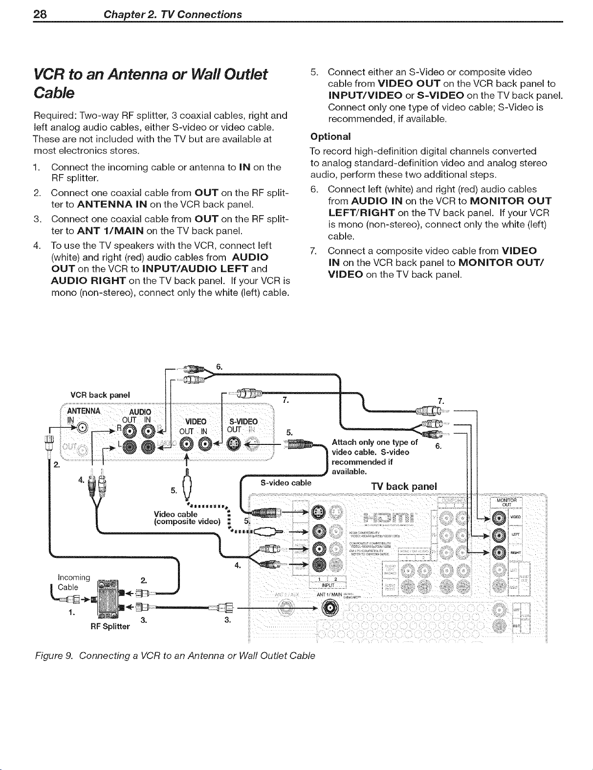
VCR to an Antenna or Wall Outlet
Cable
Required: Two-way RF splitter, 3 coaxial cables, right and
left analog audio cables, either S-video or video cable.
These are not included with the TV but are available at
most electronics stores.
1. Connect the incoming cable or antenna to IN on the
RF splitter.
2. Connect one coaxial cable from OUT on the RF split-
ter to ANTENNA IN on the VCR back panel.
3. Connect one coaxial cable from OUT on the RF split-
ter to ANT l/MAIN on the TV back panel.
4. To use the TV speakers with the VCR, connect left
(white) and right (red) audio cables from AUDIO
OUT on the VCR to INPUT/AUDIO LEFT and
AUDIO RIGHT on the TV back panel, If your VCR is
mono (non-stereo), connect only the white (left) cable,
5.
Connect either an S-Video or composite video
cable from VIDEO OUT on the VCR back panel to
INPUT/VIDEO or S=VlDEO on the TV back panel.
Connect only one type of video cable; S-Video is
recommended, if available.
Optional
To record high-definition digital channels converted
to analog standard-definition video and analog stereo
audio, perform these two additional steps.
6. Connect left (white) and right (red) audio cables
from AUDIO IN on the VCR to MONITOR OUT
LEFT/RIGHT on the TV back panel. If your VCR
is menu (non-stereo), connect only the white (left)
cable.
7. Connect a composite video cable from VIDEO
IN on the VCR back panel to MONITOR OUT/
VIDEO on the TV back panel.
VCR back panel
Incoming
Cable
1.
RF Splitter
Figure 9. Connecting a VCR to an Antenna or Wall Outlet Cable
MONITOR
OUT
_.® 0to
Chapter 2. TV Connections 29
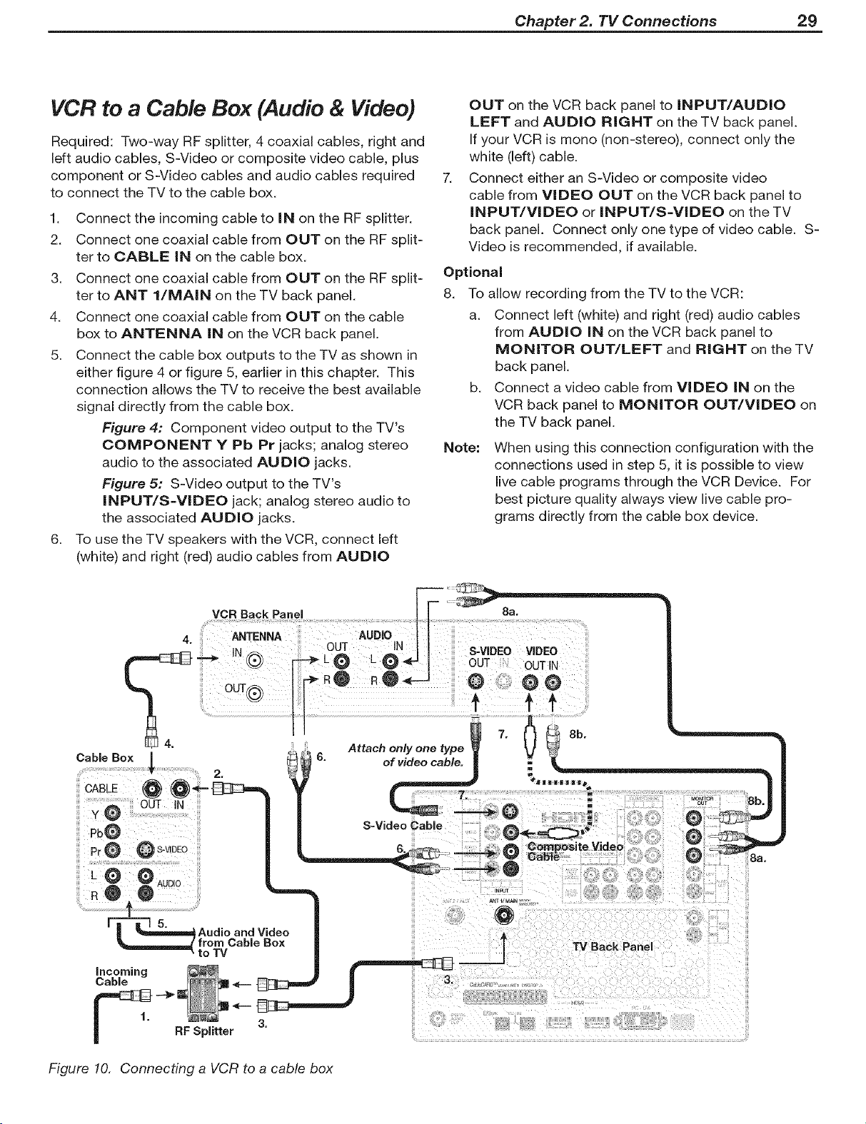
VCR to a Cable Box (Audio & Video)
Required: Two-way RF splitter, 4 coaxial cables, right and
left audio cables, S-Video or composite video cable, plus
component or S-Video cables and audio cables required
to connect the TV to the cable box.
1. Connect the incoming cable to iN on the RF splitter.
2. Connect one coaxial cable from OUT on the RF split-
ter to CABLE iN on the cable box.
3. Connect one coaxial cable from OUT on the RF split-
ter to ANT l/MAIN on the TV back panel.
4. Connect one coaxial cable from OUT on the cable
box to ANTENNA iN on the VCR back panel.
5. Connect the cable box outputs to the TV as shown in
either figure 4 or figure 5, earlier in this chapter. This
connection allows the TV to receive the best available
signal directly from the cable box.
Figure 4: Component video output to the TV's
COMPONENT Y Pb Pr jacks; analog stereo
audio to the associated AUDIO jacks.
Figure 5: S-Video output to the TV's
INPUT/S=VlDEO jack; analog stereo audio to
the associated AUDIO jacks.
6. To use the TV speakers with the VCR, connect left
(white) and right (red) audio cables from AUDIO
OUT on the VCR back panel to INPUT/AUDIO
LEFT and AUDIO RIGHT on the TV back panel.
If your VCR is mono (non-stereo), connect only the
white (left) cable.
7.
Connect either an S-Video or composite video
cable from VIDEO OUT on the VCR back panel to
INPUT/VIDEO or INPUT/S-VIDEO on the TV
back panel. Connect only one type of video cable. S-
Video is recommended, if available.
Optional
8. To allow recording from the TV to the VCR:
a. Connect left (white) and right (red) audio cables
from AUDIO iN on the VCR back panel to
MONITOR OUT/LEFT and RIGHT on the TV
back panel.
b. Connect a video cable from VIDEO iN on the
VCR back panel to MONITOR OUT/VIDEO on
the TV back panel.
Note: When using this connection configuration with the
connections used in step 5, it is possible to view
live cable programs through the VCR Device. For
best picture quality always view live cable pro-
grams directly from the cable box device.
6. of video cable.
Aodioo°dVidoo
Incoming
Cable
5.
_===,,=,,=,,=,,=,,=Jfrom Cable Box
1.
• to TV
RFSplitter
3.
Figure 10. Connecting a VCR to a cable box
Attach only one type
S-Video Cable
7.
m
7.
TV Back Panel

30 Chapter 2. 71/Connections
HDMI Device (Cable Box, Satellite
Receiver, DVD Player, or Other Device)
Required: HDMI-to-HDMI cable. This is not included
with the TV.
Connect an HDMI cable from the TV back panel to the
HDMI device output. HDMI devices provide video and
audio through this cable, so no other connection is
required. You can connect two HDMI devices to the TV
back panel through the HDMI connections.
TV Back Panel
HDMI Device
Figure 11. Connecting an HDMI device.
DV! Video Device (Cable Box,
Satellite Receiver, DVD Player, or
Other Device)
Analog stereo audio cables and a DVI=to=HDMI cable or
DVl/HDMI adapter and HDMI cable are required. These
are not included with the TV. They may be available at
your local electronics retailer.
1. Connect the DVI=to=HDMI cable (recommended) or
HDMI cable with DVl/HDMI adapter from the DVI
device's back panel to the TV back panel.
NOTE: If you are using a DVl/HDMI adapter, it is impor-
tant to connect the adapter to the DVI device for
best performance.
2. Connect a set of audio cables from AUDIO OUT
on the DVI device back panel to the HDMI/DVl
AUDIO on the TV back panel. Connect the red
cable to the RIGHT jack and the white cable to the
LEFT jack.
NOTE:
The HDMI connection supports copy protection
(HDCP).
Some devices require connecting to an analog
input first, in order to view on-screen menus and
to select DVl as the ouput. Please review your
equipment instructions for DVl connectivity and
compatibility.
Note: HDMI inputs are Simplay/-/z_ certified for proper
interoperability with other products certified by Sim-
playTM.
IMPORTANT
To connect a personal computer to the TV,
see chapter 6, "Using the TV with a Personal
Computer."
The NDIVll input processes signals as standard
motion video and is not designed to process
computer resolutions.
Figure 12. Connecting a DVI device
Chapter 2. TV Connections 31
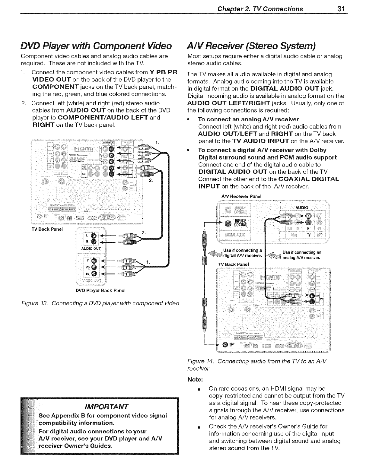
DVD Player with Component Video
Component video cables and analog audio cables are
required. These are not included with the TV.
1. Connect the component video cables from Y PB PR
VIDEO OUT on the back of the DVD player to the
COMPONENT jacks on the TV back panel, match-
ingthe red, green, and blue colored connections.
2. Connect left (white) and right (red) stereo audio
cables from AUDIO OUT on the back of the DVD
player to COMPONENT/AUDIO LEFT and
RIGHT on the TV back panel.
A/V Receiver (Stereo System)
Most setups require either a digital audio cable or analog
stereo audio cables,
The TV makes all audio available in digital and analog
formats. Analog audio coming into the TV is available
in digital format on the DIGITAL AUDIO OUT jack.
Digital incoming audio isavailable in analog format on the
AUDIO OUT LEFT/RNGHTjacks. Usually, only one of
the following connections is required:
• To connect an analog A/V receiver
Connect left (white) and right (red) audio cables from
AUDIO OUT/LEFT and RIGHT on the TV back
panel to the TV AUDIO iNPUT on the A/V receiver.
To connect a digital A/V receiver with Dolby
Digital surround sound and PCM audio support
Connect one end of the digital audio cable to
DIGITAL AUDIO OUT on the back of the TV.
Connect the other end to the COAXIAL DIGITAL
INPUT on the back of the A/V receiver.
AN Receiver Panel
TV Back Panel
DVD Player Back Panel
Figure 13. Connecting a DVD player with component video
IN
i Use if connecting a _, Use if connecting an
I_
Figure 14. Connecting audio from the TV to an A/V
receiver
Note:
[]
On rare occasions, an HDMI signal may be
copy-restricted and cannot be output from the TV
as a digital signal. To hear these copy-protected
signals through the A/V receiver, use connections
for analog A/V receivers.
Check the A/V receiver's Owner's Guide for
information concerning use of the digital input
and switching between digital sound and analog
stereo sound from the TV.
32 Chapter 2. TV Connections
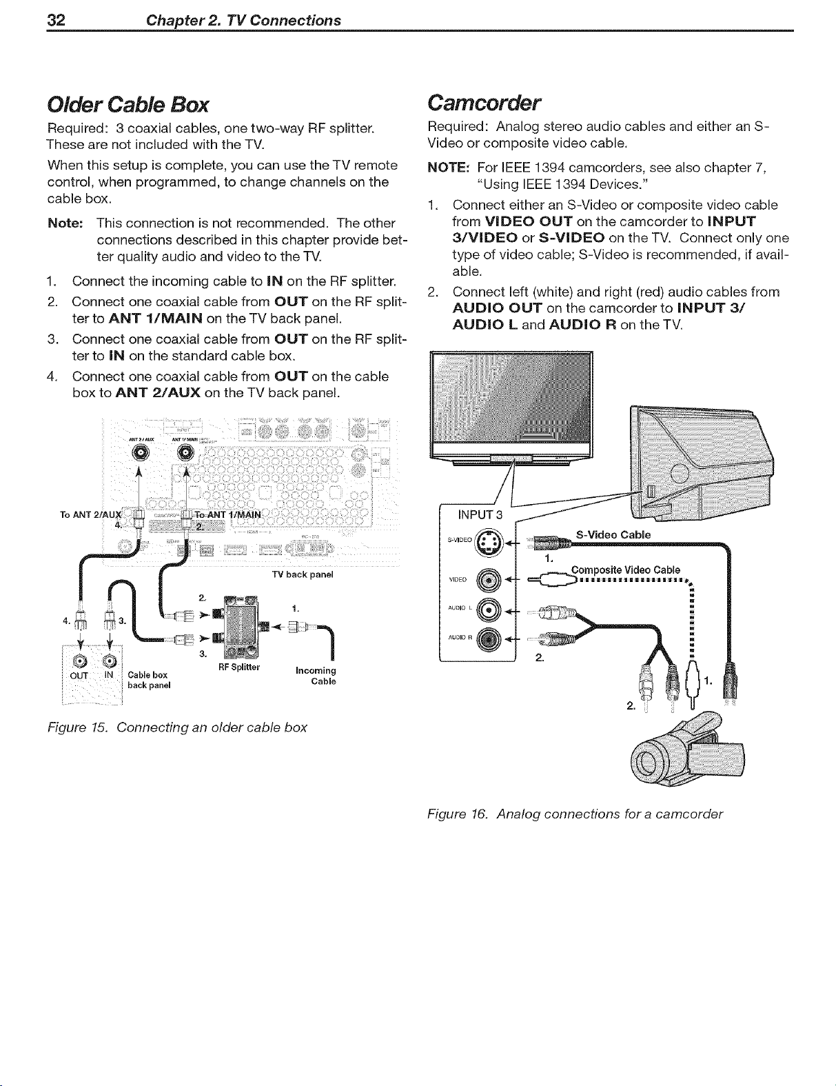
Older Cable Box
Required: 3 coaxial cables, one two-way RF splitter.
These are not included with the TV.
When this setup is complete, you can use the TV remote
control, when programmed, to change channels on the
cable box.
Note: This connection is not recommended. The other
connections described in this chapter provide bet=
ter quality audio and video to the TV.
1. Connect the incoming cable to iN on the RF splitter.
2. Connect one coaxial cable from OUT on the RF split=
ter to ANT l/MAIN on the TV back panel.
3. Connect one coaxial cable from OUT on the RF split=
ter to IN on the standard cable box.
4. Connect one coaxial cable from OUT on the cable
box to ANT 2/AUX on the TV back panel.
Camcorder
Required: Analog stereo audio cables and either an S-
Video or composite video cable.
NOTE: For IEEE 1394 camcorders, see also chapter 7,
"Using IEEE 1394 Devices."
1. Connect either an S-Video or composite video cable
from VIDEO OUT on the camcorder to iNPUT
3/VIDEO or S=VIDEO on the TV. Connect only one
type of video cable; S-Video is recommended, if avail-
able.
2. Connect left (white) and right (red) audio cables from
AUDIO OUT on the camcorder to iNPUT 3/
AUDIO L and AUDIO R on the TV.
Figure 15. Connecting an older cable box
S-Video Cable
1.
omposite Video Cable
m
w
2. 2 1.
Figure 16. Analog connections for a camcorder
 Loading...