

Mitsubishi WD-62627, WD-52627 Owner’s Manual
DIGITAL TELEVISlrlNB"
HIGH DEFINITION MULTIMEDmA _NTER_ACE
_Lin( °
TV Unformation:
Use this space to record the model and serial numbers of
your television. This information is on the back of your TV
Model number
Serial number
v_s_t our bs_t÷
RISK OF ELECTRmC SHOCK
DO NOT OPEN
CAUTION: TO REDUCE THE RISK OF ELECTRIC SHOCK, DO NOT REMOVE COVER (OR
BACK). NO USER SERVICEABLE PARTS INSIDE. REFER SERVICING TO QUALIFIED SERVICE
PERSONNEL.
The exclamation point within an equiHateraHtriangHe is intended to aHertthe user to the presence of
important operating and maintenance (servicing) instructions in the Hiterature accompanying the appHiance.
This TV is heavy! Exercise extreme care when lifting or moving. Lifting or moving the TV requires a
minimum of two adults. To prevent damage to your TV, your TV shouUd not be jarred or moved whiRe it is
turned on. Power off your TV before moving it.
Portions of the advanced circuitry of this TV must continue to operate even when the TV is turned off.
Some of these circuits therefore need to be cooled at all times. A low power standby fan may be heard in
a quiet environment. This is normal operation.
Custom cabinet installation must allow for proper air circulation around the television.
TV Guide On Screen® Access Requirements
TV Guide On Screen listings are not provided by Mitsubishi Digital Electronics America, Inc. Operation of TV Guide
On Screen requires over-the-air or cable access to stations carrying TV Guide On Screen program listings. If listings
are not available in your area or become discontinued by the local provider, TV Guide On Screen will not operate. TV
Guide On Screen does not provide program listings for satellite TV systems.
Stand Requirement
CAUTION: Mitsubishi TV model WD-52627 is for use only with Mitsubishi stand model MB-52527. Mitsubishi TV
model WD-62627 is for use only with Mitsubishi stand model MB-62527. Use with other stands is capable of resulting
in instability causing possible injury.
Lamp Repmacement
The image on this TV is produced by a high-brightness lamp that will operate for many hours. Eventually, however, this
lamp will need to be replaced. It is designed to be easily replaced by the TV owner. Front panel indicators and/or on-
screen messages will assist you in determining when the lamp needs to be replaced. Please see Appendix H for details
on lamp replacement.
To order a new lamp:
While Under Warranty
Call (800) 332-2119. Please have model number, serial
number, and TV purchase date available.
WARNING: TO REDUCE THE RISK OF FIRE OR ELECTRIC SHOCK, DO NOT EXPOSE THIS APPLIANCE TO RAIN OR
MOISTURE.
Call (800) 553-7278. Order lamp part number
After Warranty t
915P026010.
CAUTION: TO PREVENT ELECTRIC SHOCK, MATCH WIDE BLADE OF PLUG TO WIDE SLOT, FULLY INSERT.
NOTE TO CATV SYSTEM iNSTALLER: THIS REMINDER iS PROVIDED TO CALL THE CATV SYSTEM INSTALLER'S
ATTENTION TO ARTICLE 820-40 OF THE NEC THAT PROVIDES GUIDELINES FOR THE PROPER GROUNDING AND,
IN PARTICULAR, SPECIFIES THAT THE CABLE GROUND SHALL BE CONNECTED TO THE GROUNDING SYSTEM OF
THE BUILDING, AS CLOSE TO THE POINT OF CABLE ENTRY AS PRACTICAL.
FCC Declaration of Conformity
Product:
ModeUs:
Projection Television Receiver
WD-52627, WD-62627
ResponsibUe Party: Mitsubishi DigitaU EUectronics America, Rnc.
9351 Jeronimo Road
Rrvine, CA 92618-1904
Telephone:
This device compHies with Part 15 of the FCC RuHes. Operation is subject to the following two conditions:
(1)This device may not cause harmfuH interference, and
(2) this device must accept any interference received, incHuding interference that may cause undesired operation.
Note: This equipment has been tested and found to compHy with the Himitsfor a CHassB digitaH device, pursuant to
part 15of the FCC Rules. These limits are designed to provide reasonable protection against harmful interference in
a residential installation. This equipment generates, uses and can radiate radio frequency energy and, if not installed
and used in accordance with the instructions, may cause harmful interference to radio communications. However,
there is no guarantee that interference will not occur in a particular installation. If this equipment does cause harmful
interference to radio or television reception, which can be determined by turning the equipment off and on, the user
is encouraged to try to correct the interference by one or more of the following measures:
949-465-6000
Reorient or relocate the receiving antenna.
Increase the separation between the equipment and the receiver.
Connect the equipment into an outlet on a circuit different from that to which the receiver is connected.
Consult the dealer or an experienced radioiTV technician for help.
Changes or modifications not expressly approved by lViitsubishi could cause harmful interference and would
void the user's authority to operate this equipment.
IMPORTANT SAFEGUARDS
PUease read the foHowJncj safeguards for your TV and retain for future reference. AUways follow aH
wamJncjs and instructions marked on the teUevJsJon.
1.
Read, Retain and Follow All mnstructions
Read aH safety and operating instructions before operating the TV. Retain the safety and operating instructions
for future reference. Follow aft operating and use instructions.
2.
Heed Warnings
Adhere to aHwarnings on the appHiance and in the operating instructions.
3.
Cleaning
Unplug the TV from the wall outlet before cleaning. Do not use liquid, abrasive or aerosol cleaners. Cleaners can
permanently damage the cabinet and screen. Use a lightly dampened cloth for cleaning.
4.
Attachments and Equipment
Never add any attachments and/or equipment without approval of the manufacturer as such additions may result
in the risk of fire, electric shock or other 3ersonal injury.
5.
Water and Moisture
Do not use the TV where contact with or ummersion in water is possible. Do not use near bath tubs, wash bowls,
kitchen sinks, laundry tubs, swimming pools, etc.
6. Accessories
serious injury to a child or adult and serious damage to the TV. Use only with a cart, stand,
tripod, bracket or table recommended by the manufacturer, or sold with the TV. Any mounting
of the TV should follow the manufacturer's instructions, and should use mounting accessories
recommended by the manufacturer.
Do not place the TV on an unstable cart, stand, tripod, or table. The TV may fall, causing
An appliance and cart combination should be moved with care. Quick stops, excessive force,
and uneven surfaces may cause the appliance and cart combination to overturn.
Ventilation
7.
Slots and openings in the cabinet are provided for ventilation and to ensure reliable operation of the TV and to
protect it from overheating. Do not block these openings or aflow them to be obstructed by placing the TV on a
bed, sofa, rug, or other similar surface. Nor should it be placed over a radiator or heat register, ifthe TV is to be
placed in a rack or bookcase, ensure that there is adequate ventilation and that the manufacturer's instructions
have been adhered to.
8.
Power Source
This TV should be operated only from the type of power source indicated on the marking label. If you are not sure
of the type of power supplied to your home, consult your appliance dealer or local power company.
g.
Grounding or Polarization
This TV is equipped with a polarized alternating current line plug having one blade wider than the other. This plug
will fit into the power outlet only one way. Ifyou are unable to insert the plug fully into the outlet, try reversing the
plug. If the plug should still fail to fit, contact your electrician to replace your obsolete outlet. Do not defeat the
safety purpose of the polarized plug.
10.
Power-Cord Protection
Power-supply cords should be routed so that they are not likely to be walked on or pinched by items placed
upon or against them, paying particular attention to cords at plugs, convenience receptacles, and the point
where they exit from the TV.
11.
Lightning
For added protection for this TV during a lightning storm, or when it is left unattended and unused for long
period of time, unplug it from the wall outlet and disconnect the antenna or cable system. This will prevent
damage to the TV due to lightning and power-line surges.
4
IMPORTANT SAFEGUARDS, continued
12.
Power Lines
An outside antenna system shouid not be ]ocated in the vicinity of overhead power Hinesor other ebctrb Hightor
power circuits, or where it can fall into such power Hinesor circuits. When k_staHing an outside antenna system,
extreme care should be taken to keep from touching such power lines or circuits as contact with them might be
fatal.
13.
Overloading
Do not overload wall outlets and extension cords as this can result in a risk of fire or electric shock.
14.
Object and Liquid Entry
Never push objects of any kind into this TV through openings asthey may touch dangerous voltage points or short-
out parts that could result in fire or electric shock. Never spill liquid of any kind on or into the TV.
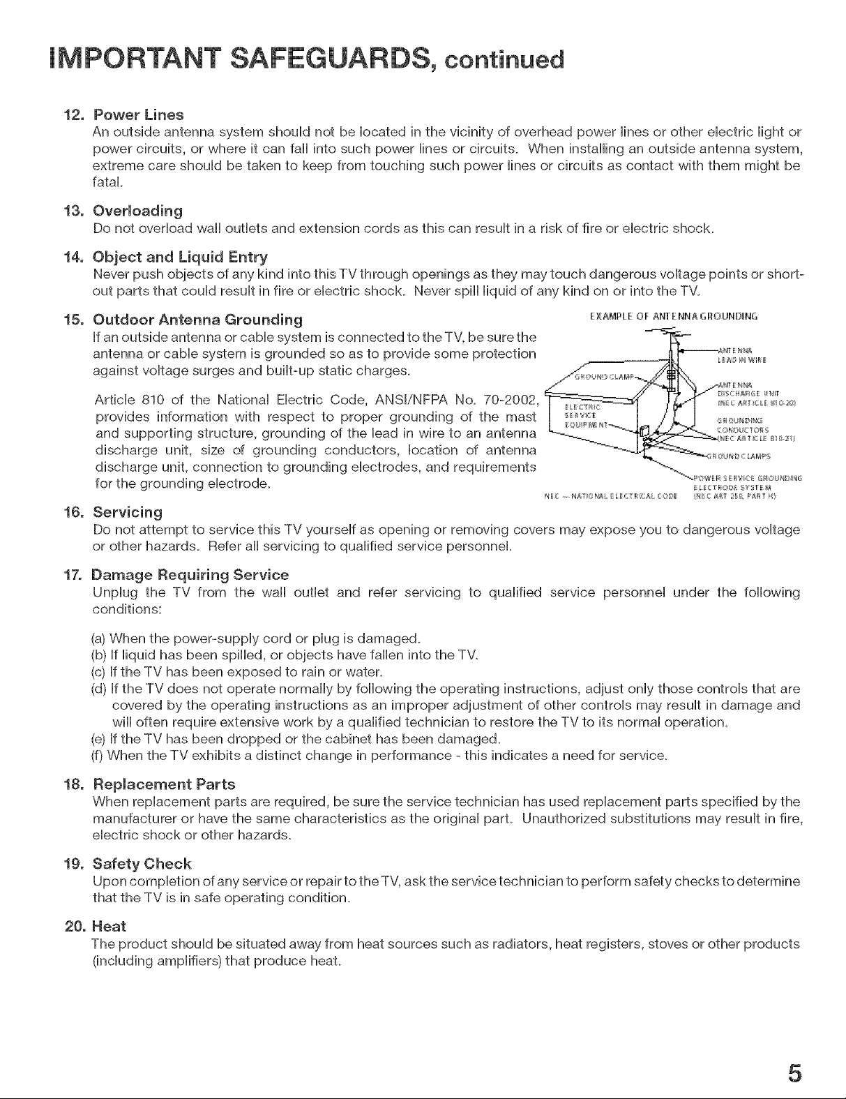
15.
Outdoor Antenna Grounding
If an outside antenna or cable system is connected to the TV, be sure the
antenna or cable system is grounded so as to provide some protection
against voltage surges and built-up static charges.
Article 810 of the National Electric Code, ANSI/NFPA No. 70-2002,
provides information with respect to proper grounding of the mast
and supporting structure, grounding of the lead in wire to an antenna
discharge unit, size of grounding conductors, location of antenna
discharge unit, connection to grounding electrodes, and requirements
for the grounding electrode.
EXAMPLE OF ANT ENNA GI:IOIJNDING
16.
Servicing
Do not attempt to service this TV yourself as opening or removing covers may expose you to dangerous voltage
or other hazards. Refer aii servicing to qualified service personnel.
17.
Damage Requiring Service
Unplug the TV from the wall outlet and refer servicing to qualified service personnel under the following
conditions:
(a) When the power-supply cord or plug is damaged.
(b) If liquid has been spilled, or objects have fallen into the TV.
(c) If the TV has been exposed to rain or water.
(d) If the TV does not operate normally by following the operating instructions, adjust only those controls that are
covered by the operating instructions as an improper adjustment of other controls may result in damage and
wiii often require extensive work by a qualified technician to restore the TV to its normal operation.
(@If the TV has been dropped or the cabinet has been damaged.
(f) When the TV exhibits a distinct change in performance - this indicates a need for service.
18.
Replacement Parts
When replacement parts are required, be sure the service technician has used replacement parts specified by the
manufacturer or have the same characteristics as the original part. Unauthorized substitutions may result in fire,
electric shock or other hazards.
19.
Safety Check
Upon completion of any service or repair to the TV, ask the service technician to perform safety checks to determine
that the TV is in safe operating condition.
20.
Heat
The product should be situated away from heat sources such as radiators, heat registers, stoves or other products
(including amplifiers) that produce heat.
5
Chapter 1: Television Overview
TV Accessories ..................................................................... 10
Special Features .................................................................... 11
Front Control Panel ................................................................. 12
Remote Control
Overview ....................................................................... 14
Battery Installation .............................................................. 15
Care ........................................................................... 15
Sleep Timer ..................................................................... 15
TV Back Panel ...................................................................... 16
Media Card Slots ................................................................... 18
Front-Panel Input 3 .................................................................. 18
Using the System Reset Button ....................................................... 19
Using the Reset Menu to Reset the TV ................................................ 19
Chapter 2: Connecting
External Devices and NetCommand® Setup ........................................... 22
CableCARD TM Technology ........................................................... 23
Wall Outlet Cable ................................................................... 24
Standard Cable Box ................................................................. 24
Antenna with a Single Lead .......................................................... 25
Antennas with Separate UHF and VHF Leads .......................................... 25
VCR to an Antenna or Wall Outlet Cable (Audio & Video) ................................. 26
VCR to a Cable Box (Audio & Video) ................................................... 27
A/V Receiver (Stereo System) ........................................................ 28
Satellite Receiver or Other Device with SWideo ........................................ 28
DVD Player with Component Video ................................................... 29
DVI Device ......................................................................... 29
HDTV Cable Box or Satellite Receiver with Component Video ........................... 30
HDMI Device ....................................................................... 30
Computer with an HDMI Monitor Output ............................................... 31
Computer with a DVI Monitor Output .................................................. 31
IR Emitter NetCommand® ........................................................... 32
Compatible IEEE 1394 Devices ....................................................... 33
Helpful Hints ....................................................................... 35
Chapter 3: NetCommand® Setup and Editing
NetCommand® Introduction ......................................................... 38
Using the Remote Control with NetCommand® ........................................ 39
NetCommand® Setup On-Screen Buttons ............................................. 40
3D Graphical _11_1_i11[Menu System ................................................... 41
NetCommand® Initial Setup ......................................................... 42
Edit NetCommand®: Add an A/V Receiver ............................................ 45
Edit NetCommand®: Add Devices ................................................... 48
Edit NetCommand®: Change or Delete Devices ....................................... 52
Chapter 4: IEEE 1394 Devices and NetCommand@-Controlled Recordings
IEEE 1394 Devices and NetCommand® Control ........................................ 54
Adding IEEE 1394 Devices Automatically .............................................. 55
Device Selection Menu .............................................................. 57
Using the Device Menu Button to Display Menus ....................................... 58
Using the GUIDE Button to Display ChanneIView TM and Menus .......................... 59
NetCommand@-Controlbd Recordings ............................................... 60
Chapter 5: TV Menu Screen Operations
Main Menu ......................................................................... 64
Setup Menu ....................................................................... 65
NetCommand® Menu .............................................................. 67
Record Menu ....................................................................... 68
Channel Menu ..................................................................... 70
Captions Menu ..................................................................... 72
V-Chip Lock Menu .................................................................. 74
Audio/Video Menu .................................................................. 77
A/V Setting Descriptions: Audio ...................................................... 78
A/V Setting Descriptions: Video ...................................................... 79
Chapter 6: Add#ional Features
Operation of PIP .................................................................... 82
TV Display Formats ................................................................. 83
PC Viewing ......................................................................... 85
PC Display Formats ................................................................. 86
MediaCommand TM and Media Card Playback .......................................... 87
Chapter 7: Troubteshootin 9 ........................................................ 89
Appendices
Appendix
Appendix
Appendix
Appendix
Appendix
Appendix
Appendix
Appendix H: Lamp Cartridge Replacement ........................................... 109
A: Bypassing the V-Chip Lock .............................................. 97
B: Specifications .......................................................... 99
C: Remote Control Programming Codes .................................... 101
D: Device Control with NetCommand@ ..................................... 104
E: NetCommand@ Specialized Device Keys ................................. 106
F: On-Screen Information Displays ......................................... 107
G: Cleaning and Service .................................................. 108
Trademark and License Information ............................................. 111
Index .................................................................................. 113
Mitsubishi DLP TM Projection Television Limited Warranty .................... 115
Thanks...
Thank you for choosing Mitsubishi as your premier Home Entertainment provider
This Owner's Guide describes the features and functions of your Mitsubishi
widescreen, high definition TV. We urge you to examine this Owner's Guide to
become familiar with the innovative features and operations this unique television
offers.
The very core of our corporate philosophy is to provide our customers with the
very best. Our development team at Mitsubishi has worked to provide you with
a television that defines "state-of-the-art," with the capability to meet your needs
now and in the future.
8
Whether this is your first Mitsubishi electronic product, or an addition to your
Mitsubishi coflection, we believe you and your family will continue to enjoy your
Mitsubishi home theater for many years.
Thank you,
Mitsubishi DigitaJ EJectronics America, Inc.
R m m A m
,(eV(S(On uverv(ew
TV Accessories ..................................... 10
SpeciaU Features .................................... 11
Front Control Pane) .................................. 12
Remote ControU
Overview ........................................ 14
Battery Installation .................................. 15
Care ........................................... 15
S(eep Timer ...................................... 15
TV Back PaneU ..................................... 16
Media Card SUots ................................... 18
Front-PaneU Input 3 .................................. 18
Using the System Reset Button ......................... 19
Using the Reset Menu to Reset the TV .................... 19
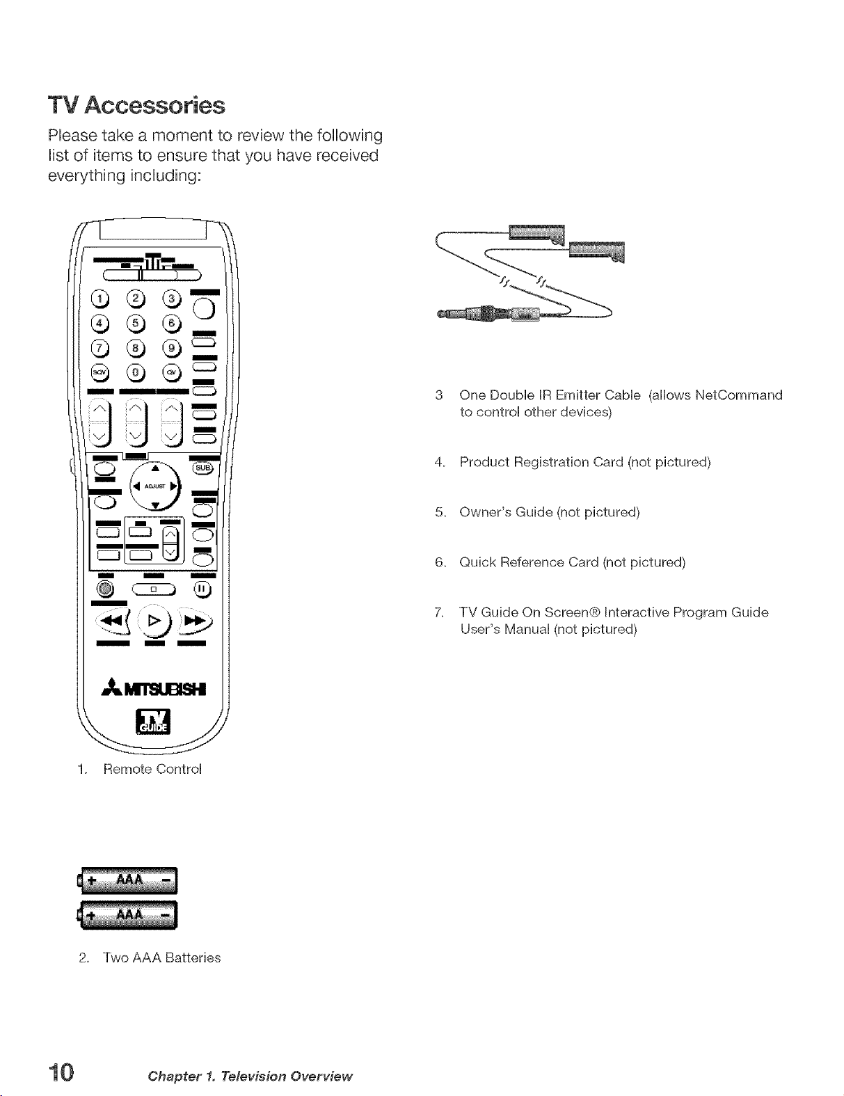
TV Accessories
Phase take a moment to review the following
Uistof items to ensure that you have received
everything incUuding:
3 One Doubb BREmitter Cabb (allows NetCommand
to controi other devices)
4. Product Registration Card (not pictured)
IIIIIIIII m
m
1. Remote Control
@
5. Owner's Guide (not pictured)
6. Quick Reference Card (not pictured)
7_
TV Guide On Screen@ Interactive Program Guide
User's Manual (not pictured)
2. Two AAA Batteries
10 Chapter 1. Television Overview
SpeciaJ Features
Your new High Definition widescreen television has many speciaJ features that make it the perfect center of
your home entertainment system, incRuding:
High Definition DLP TM DispJay System
Your widescreen MitsubisM HDTV uses Texas hstruments most advanced DigitaHLight Processing TM technoHogy
for rear projection teHevisions. This TV is truHya high-performance muHtimedia monitor uniqueHy capaMe of both
stunning high-definition video images and clear, detailed, high-resolution PC images. Your TV is able to accept
video signals from an antenna or direct cable in standard video scanning rates of 480i, 480p, 720p, 1080i and
1080p. It is also able to accept, through the HDMI 2 connection, signals with PC resolutions from VGA (640 x 480)
through XGA (1024 x 768). When used with a compatible graphics card and controlling software, this TV is also
able to accept the custom PC resolution of 720p (1280 x 720). When connecting a PC to HDMI you will need a PC
video card with DVJor HDMI output. Also, so the TV can apply the correct PC signal processing, you will need to
set up the TV to receive the PC signals through the HDMI 2 input by using the NetCommand setup system. All of the
compatible video and PC signals will be converted to 1080p for final display; some signals will, however, add black
side bars, top and bottom bars, or both to fill the screen, and some signals will display standard video overscan.
TV Guide On Screen@ interactive Program Guide System
An eight-day on-screen program guide that can be used with cable, over-the-air and CableCARD TM reception. The
subscription-free guide system lists regular, digital and high-defintion programming. This system allows multiple
sorting options and easy program recording. Program listings are downloaded while your TV is turned off, so that
you have current program information available every day. Note that when the system is first set up, it may take up
to 24 hours to begin to receive TV program listings. It may take one week to receive all eight days of TV program
listings.
DigitaJ CabJe Ready (CabJeOARD TM)
Your widescreen Mitsubishi HDTV is "Plug-and-Play" ready, it can descramble a cable provider's one-way digital
signals with the use of a CableCARD security module. The CableCARD is used in place of a traditional cable box
to access digital cable programming (including high definition). Contact your local cable provider for availability
information and service details.
NetCommand ® Home Network ControJ System
Your widescreen Mitsubishi HDTV offers a new level of networking to combine selected older products with new
and future digital products. NetCommand supports IEEE 1394 connections, Audio Video Control system (AViC),
5C copy protection and IR control of selected older products such as VCRs, DVD players, cable boxes or satellite
receivers. NetCommand includes the ability to learn remote control signals directly from many devices, allowing you
to customize the NetCommand system in a way that works best for your viewing
16:9 Widescreen Picture Format
Enjoy a full theatrical experience in the comfort of your home. View pictures as film directors intended them. Digital
TV broadcasts, DVDs and newer video game consoles support this widescreen format.
Media Cards
You can display a slide show of your favorite JPEG pictures or listen to MP3 or WMA audio selections that have been
recorded on compatible media cards
Chapter 1. Television Overview
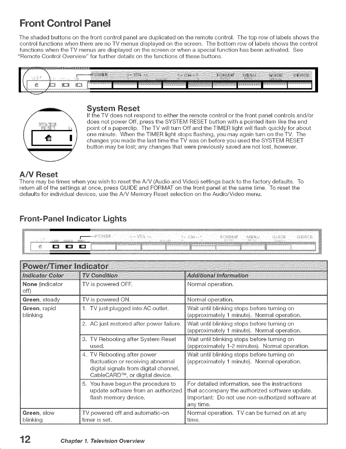
Front Control Panel
The shaded buttons on the front control panel are duplicated on the remote control. The top row of labels shows the
control functions when there are no TV menus displayed on the screen. The bottom row of labels shows the control
functions when the TV menus are displayed on the screen or when a special function has been activated. See
"Remote Control Overview" for further details on the functions of these buttons.
System Reset
If the TV does not respond to either the remote controi or the front panei controis and/or
does not power Off, press the SYSTEM RESET button with a pointed item like the end
point of a paperclip. The TV wiii turn Off and the TIMER light wiii flash quickly for about
one minute. When the TIMER light stops flashing, you may again turn on the TV. The
changes you made the last time the TV was on before you used the SYSTEM RESET
button may be lost; any changes that were previously saved are not lost, however.
A/V Reset
There may be times when you wish to reset the AiV (Audio and Video) settings back to the factory defaults. To
return all of the settings at once, press GUIDE and FORMAT on the front panel at the same time. To reset the
defaults for individual devices, use the AiV Memory Reset selection on the Audio/Video menu.
Front-PaneJ indicator Lights
TV is powered OFR Normal operation.
off)
Green, steady TV is powered ON. Normal operation.
Green, rapid 1. TV just plugged into AC outlet. Wait until blinking stops before turning on
blinking (approximately 1 minute). Normal operation.
2. AC just restored after power failure. Wait until blinking stops before turning on
(approximately 1 minute). Normal operation.
3. TV Rebooting after System Reset Wait until blinking stops before turning on
used. (approximately 1-2 minutes). Normal operation.
4. TV Rebooting after power Wait until blinking stops before turning on
fluctuation or receiving abnormal (approximately 1 minute). Normal operation.
digital signals from digital channel,
CableCARD TM, or digital device.
5. You have begun the procedure to For detailed information, see the instructions
update software from an authorized that accompany the authorized software update.
flash memory device. Important: Do not use non-authorized software at
any time.
Green, slow TV powered off and automatic-on Normal operation. TV can be turned on at any
blinking timer is set. time.
2 Chapter 1, Television Overview
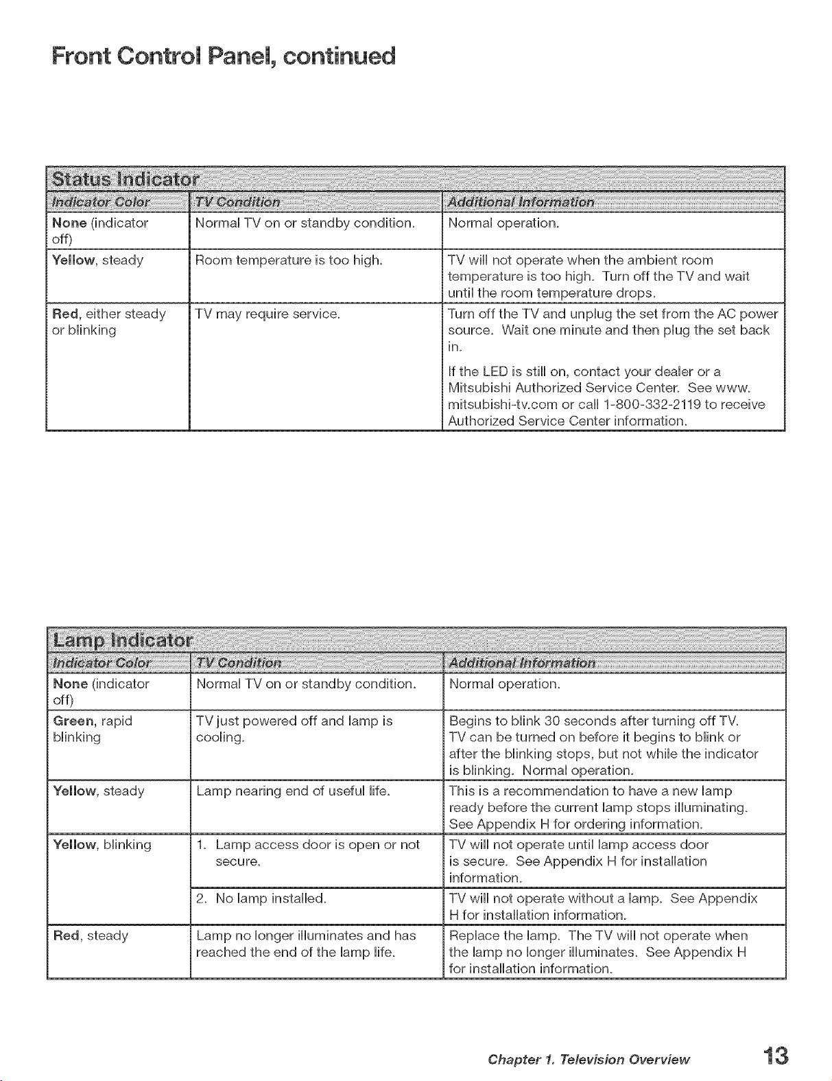
Front Control Panel, continued
None (indicator Normal TV on or standby condition. Normal operation.
off)
Yellow, steady Room temperature is too high.
TV may require service.Red, either steady
or blinking
TV wiii not operate when the ambient room
temperature is too high. Turn off the TV and wait
until the room temperature drops.
Turn off the TV and unplug the set from the AC power
source. Wait one minute and then plug the set back
in.
If the LED is still on, contact your dealer or a
Mitsubishi Authorized Service Center. See www.
mitsubishi-twcom or call 1-800-332-2119 to receive
Authorized Service Center information.
None (indicator Normal TV on or standby condition. Normal operation.
off)
Green, rapid TV just powered off and lamp is Begins to blink 30 seconds after turning off TV_
blinking cooling. TV can be turned on before it begins to blink or
after the blinking stops, but not while the indicator
is blinking. Normal operation.
Yellow, steady Lamp nearing end of useful life. This is a recommendation to have a new lamp
ready before the current lamp stops illuminating.
See Appendix H for ordering information.
1_ Lamp access door is open or not TV wiii not operate untii lamp access door
secure, is secure. See Appendix H for installation
information_
2. No lamp installed. TV wiii not operate without a lamp. See Appendix
Hfor installation information.
Red, steady Lamp no longer illuminates and has Replace the lamp. The TV wiii not operate when
reached the end of the lamp life. the lamp no longer illuminates. See Appendix H
for installation information.
Chapter 1. Television Overview
Remote ControJ
Overview
F/gure 1, following page
1. Slide Switch: SeHects AiV product to be controlled
by the remote control SeHect TV for NetCommand@
device control
2. Numbers: Individually seHectchanneHs or enter
information into menus.
3. POWER: Turns power on and off for TV and other
AiV products.
4m
GUmDE: Displays or removes TV Guide On Screen or
ChannelView for ANT-1 and 2. Displays Track List for
AiV Disc. Displays program guide for satellite receiver,
or DVD Disc menu. Displays thumbnails or play lists
for media card files.
5. SQV (SuperQuickViewTM): Scans through
memorized lists of favorite channels.
6. QV {QuickViewTM): Switches between the current
channeH and HastchanneH viewed.
7. SLEEP: Sets the TV to turn off within 2 hours. See
next page for setup instructions.
m
VmDEO:SeHects and adjusts individuaH video settings.
9.
DEVICE: DispHaysthe Device SeHection menu to
seHectthe device to view (ANT-1 and ANT-2, or
devices connected to the TV's inputs, incHuding IEEE
1394 devices).
10. DH(ANNEL)/PAGE: Scans up or down through
memorized channeHs. When used with TV Guide
On Screen@ and ChanneWiew, pages up and down
through screens.
11. VOLUME: Changes sound level.
12. AUDIO: Selects and adjusts individual audio settings.
13. MUTE: Turns sound on or off.
14. Light: Located on the left side of the remote control,
this feature illuminates buttons or labels.
15. ENTER/EXCN: Selects a channel number or menu
item. Exchange PIP and main TV picture. If PIP is
displayed, it must be cancelled before using the on-
screen menus for devices.
16. ADJUST: Press ,& V _ _ to navigate TV Guide On
Screen, menus, change settings, and move the PIP
on-screen location. Operates many NetCommand
functions.
18. TV MENU: Displays ,ViewPoiglon-screenmenusystem.
19. DEVICE MENU: DispIays or removes the options menu
for TV Guide On Screen. Displays the menu for devices
connected to the TV, including CabIeCARDTM. For VCR
or DVDs, the first press displays the transport menu, the
second press displays the VCR or DVD menu.
20. V-CNmP: Turns On or Off the V-Chip Lock.
21. PIP: Turns on PIP and cycles through PIP display
choices.
22. PIP OH: Scrolls up or down through memorized
channels for PIP
23. HOME: Exits TV on-screen menus and the TV Guide
On Screen system and returns to TV viewing.
24. FORMAT: Changes the shape and size of the main TV
picture.
25. PIP DEWCE: Displays PIP Selection menu to select
the PIP image source device
26. INFO: First press displays an on-screen summary
of the current device used and any broadcast
information available (including current V-Chip
information). See Appendix D for details. While in the
TV Guide On Screen system, press the info button to
cycle through the available info box sizes.
27. RED (Record}/CONNECT: Displays the Record
menu for setting up recordings. Records with a VCR,
sets up recordings for DVCR, IEEE 1394 devices, or
while in ChanneWiew. When Listings screen for TV
Guide On Screen is displayed, will start a recording.
CONNECT: Initiates IEEE 1394 peer-to-peer
connections.
28. STOP: Stops a VCR, DVD, AiV Disc or media card file.
29. PAUSE: Pauses a live TV picture when no PIP image is
displayed. When PIP image is visible, pauses that image.
Pauses a VCR, DVD or A/V Disc, media card file.
30. REW/REV: Rewinds a VCR. Reverses scan with a DVD,
A/V Disc or media card file.
31. PLAY: Plays a VCR, DVD, A/V Disc or media card file.
32. FF/FWD: Fast forward a VCR or media card file, or fast
play a DVD.
17. SUB/CANCEL: Clears SQV and some menu entries
and cancels recordings. For digital channels, adds
separator between major and sub channel numbers.
Chapter 1. Television Overview
Remote Control, continued
Care
For Best Results from the Remote Control:
Be within 20 feet of the equipment.
Do not press two or more buttons at the same time
unless instructed.
DEVICE CHANNEL VOLUME
CANCEL
°
CONNECT
REW/REV FF/FWDPLAY
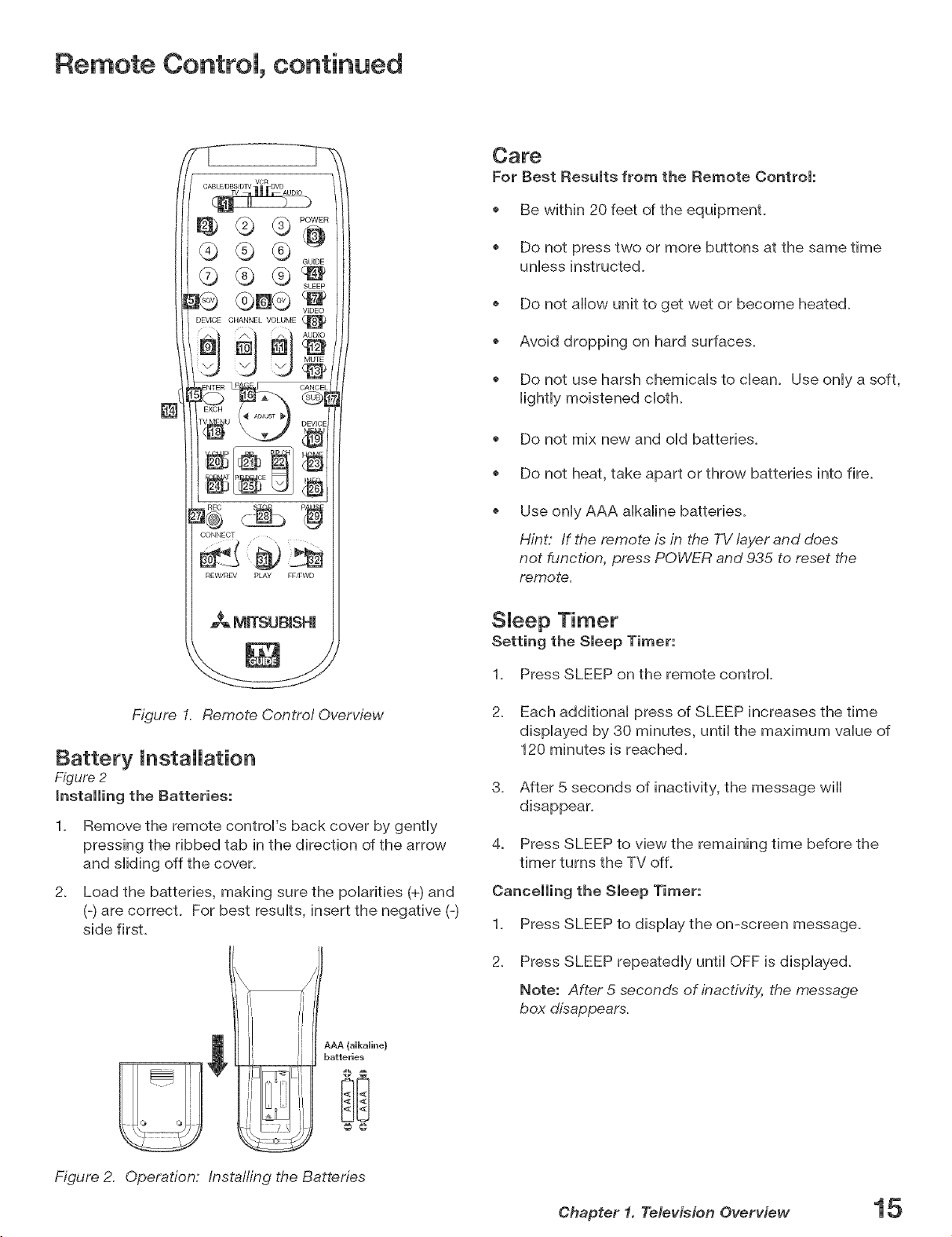
Figure 1. Remote Control Overview
Battery Installation
Figure 2
Remove the remote control's back cover by gently
pressing the ribbed tab in the direction of the arrow
and sliding off the cover.
2_
Load the batteries, making sure the polarities (+) and
(-) are correcL For best results, insert the negative (-)
side firsL
o Do not allow unit to get wet or become heated.
Avoid dropping on hard surfaces.
Do not use harsh chemicals to dean. Use only a soft,
lightly moistened cloth.
Do not mix new and old batteries.
Do not heat, take apart or throw batteries into fire.
Use only AAA alkaline batteries.
Hint: If the remote is in the TV layer and does
not function, press POWER and 935 to reset the
remote.
SJeep Timer
Setting the Sleep Timer:
1_ Press SLEEP on the remote control
2_ Each additional press of SLEEP increases the time
displayed by 30 minutes, until the maximum value of
120 minutes is reached.
3_ After 5 seconds of inactivity, the message wi[[
disappear.
4. Press SLEEP to view the remaining time before the
timer turns the TV ofL
Cancelling the Sleep Timer:
1_ Press SLEEP to display the on-screen message.
_AA (aUkaUine)
batteries
Figure 2. Operation: installing the Batteries
2_ Press SLEEP repeatedly until OFF is disp[ayed.
Note: After 5 seconds of inactivity, the message
box disappears.
Chapter 1. Tetevision Overview
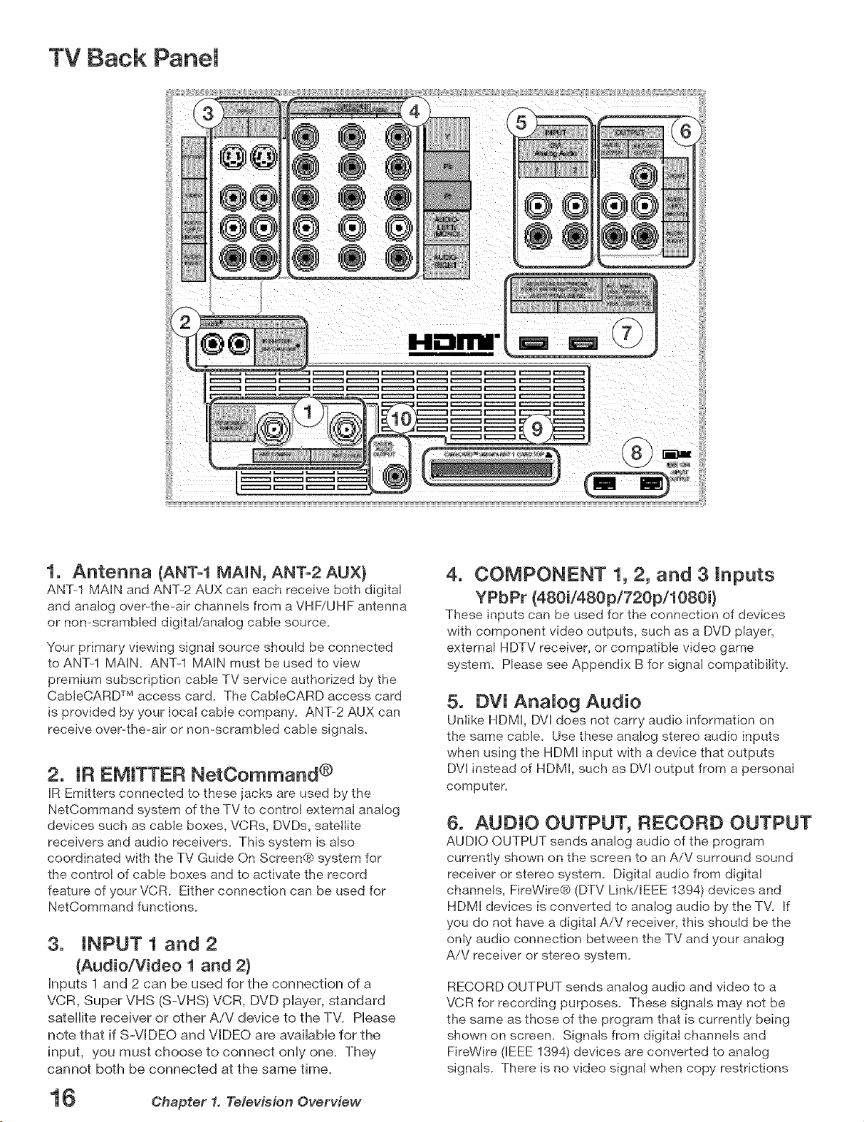
TV Back Panem
1. Antenna (ANTe1 MAIN, ANTe2 AUX)
ANT-1 MAIN and ANT-2 AUX can each receive both digital
and analog over-the-air channels from a VHF/UHF antenna
or non-scrambled digital/analog cable source.
Your primary viewing signal source should be connected
to ANT-1 MAIN. ANT-1 MAIN must be used to view
premium subscription cable TV service authorized by the
CabteCARD TM access card. The CableCARD access card
is provided by your IocaI cable company. ANT-2 AUX can
receive over-the-air or non-scrambled cable signals.
2. IR EMITTER NetOommand ®
IR Emitters connected to these jacks are used by the
NetCommand system of the TV to control external analog
devices such as cable boxes, VCRs, DVDs, satellite
receivers and audio receivers. This system is also
coordinated with the TV Guide On Screen® system for
the control of cable boxes and to activate the record
feature of your VCR. Either connection can be used for
NetCommand functions.
3. INPUT 1 and 2
(Audio/Video 1 and 2)
Inputs 1 and 2 can be used for the connection of a
VCR, Super VHS (S-VHS) VCR, DVD player, standard
satellite receiver or other AiV device to the TV. Please
note that if S-VIDEO and VIDEO are available for the
input, you must choose to connect only one. They
cannot both be connected at the same time.
4. COMPONENT 1, 2, and 3 inputs
YPbPr (480i/480p/720pi1080i}
These inputs can be used for the connection of devices
with component video outputs, such as a DVD piayer,
external HDTV receiver, or compatible video game
system. Please see Appendix B for signal compatibility.
5. DVJ AnaJog Audio
Uniike HDMI, DVl does not carry audio information on
the same cable. Use these analog stereo audio inputs
when using the HDMI input with a device that outputs
DVl instead of HDMI, such as DVl output from a personaI
computer.
6. AUDIO OUTPUT, RECORD OUTPUT
AUDIO OUTPUT sends analog audio of the program
currently shown on the screen to an A/V surround sound
receiver or stereo system. Digital audio from digital
channels, FireWire® (DTV Link/EEE 1394) devices and
HDMI devices is converted to analog audio by the TV. If
you do not have a digital A/V receiver, this should be the
only audio connection between the TV and your analog
A/V receiver or stereo system.
RECORD OUTPUT sends analog audio and video to a
VCR for recording purposes. These signals may not be
the same as those of the program that is currently being
shown on screen. Signals from digital channels and
FireWire (IEEE 1394) devices are converted to analog
signals. There is no video signal when copy restrictions
16 Chapter 1. Television Overview

TV Back Pane[, continued
are in effect. Audio alone is output when Component 1, 2,
or 3, or the HDMI input is selected for recording.
7. HDM[ TM 1 and 2
The HDMI (High Definition Multimedia interface)
supports uncompressed standard and high-definition
digital video formats and PCM digital audio format.
Use these inputs to connect to EIA/CEA=861 compliant
devices such as a high=definition receiver or DVD player.
These inputs support 480i, 480p, 720p and 1080i video
formats.
These inputs can also be used as a DVl connection with
separate analog audio inputs. An optionaI HDM[=to=DV[
adaptor or cable is necessary to make this connection
and may be available from your Iocal electronics retailer.
When using the optional HDMI=to=DVI adapter, the DV[
analog audio inputs on your TV allow you to receive left
and right audio from your DVl device.
This input is HDCP (High=Bandwidth Digital Copy
Protection) compliant.
HDM[ 2
HDM[ 2 also allows the TV to display DVl or HDMI output
from a PC. To view PC video on the TV, you must activate
the PC option in NetCommand. You can do this during
initial NetCommand setup (in the Device Setup screen),
or at any time afterwards by using the NetCommand Add
function.
access card customized to your account. This card
allows the TV to receive, decode and unscramble the
premium digital channels included in your cable TV
subscription without the use of a cable box. See page
23 for additional CabieCARD information and activation
instructions.
If your cable company is not currently offering
CabIeCARD access cards, you will need to use a
cable box provided and authorized by your local cable
company to view scrambled channels.
10. Digital Audio Output
This output sends Dolby® Digital or PCM digita[ audio to
your digital A/V surround sound receiver. Analog audio
from analog channels and devices is converted by the
TV to PCM digital audio. In most cases, this should be
the only audio connection between the TV and your A/V
receiver. If you have MP3 audio sources, however, you
need to connect the TV's analog AUDIO OUTPUT (left
and right) to your A/V receiver.
If you want audio from a PC when using PC DVl output,
you must connect the PC audio output to the TV INPUT/
DV[ Analog Audio 2, located above the HDMI 2 input.
8, DTV LinkTM/[EEE 1394
These jacks a[Iow the TV to connect to external IEEE 1394
digital products by means of a single cable. Two jacks
are provided for this purpose, which allow for a high
degree of flexibility for connecting your NetCommand
controlled system. Detailed information regarding IEEE
1394 connection requirements are in Chapter 4.
9. Cab[eOARD TM Slot
The CabIeCARD access card from your cable TV service
provider is inserted into this slot. The top of the card
should face in the direction indicated by CARD TOP _,.
CabIeCARD is a nationwide standard system that allows
your local cable TV provider to supply you with an
Chapter 1. Television Overview 17
Media Card Slots and FrontoPanei Inputs
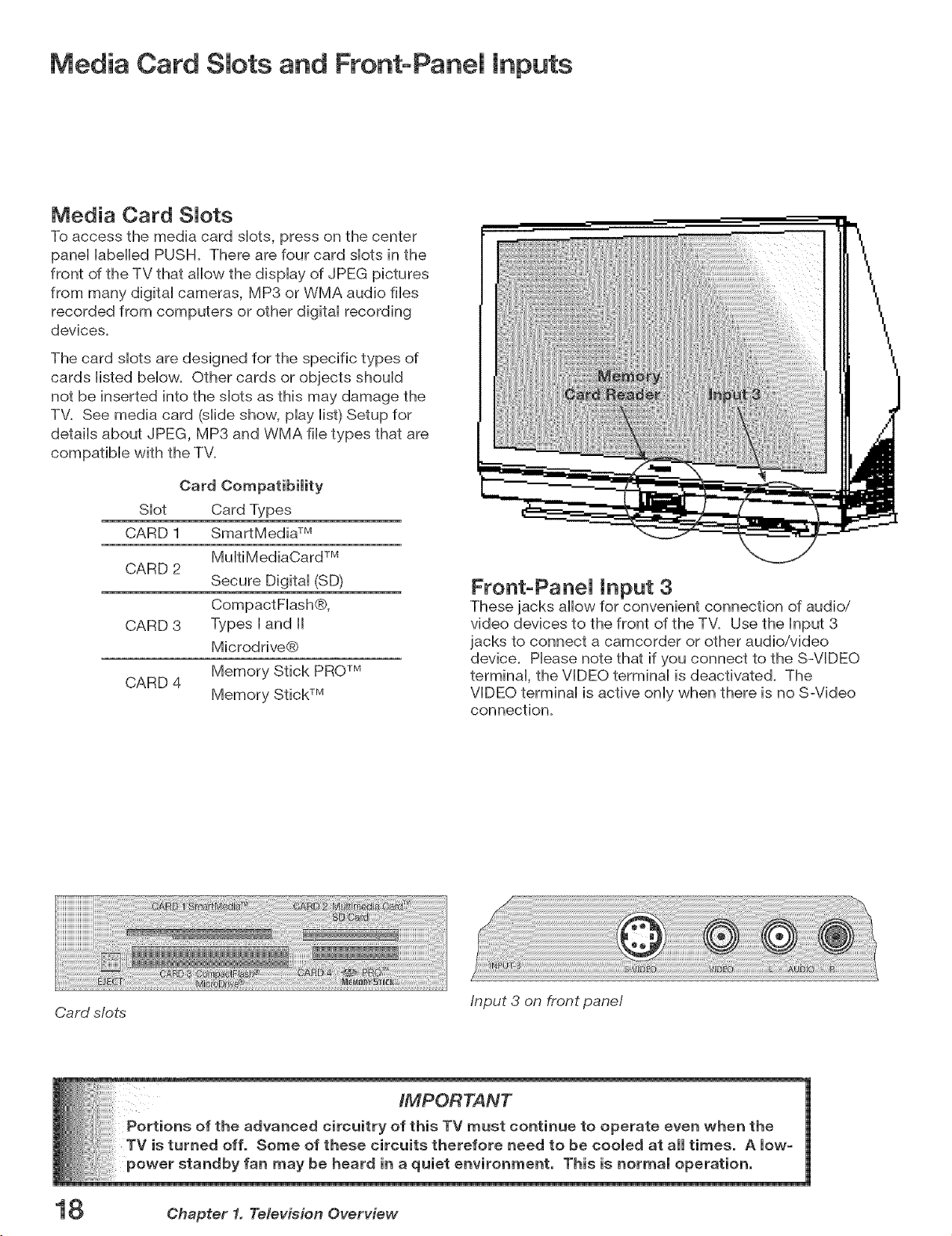
Media Card Slots
To access the media card slots, press on the center
panel labelled PUSH. There are four card slots in the
front of the TV that allow the display of JPEG pictures
from many digital cameras, MP3 or WMA audio files
recorded from computers or other digital recording
devices.
The card slots are designed for the specific types of
cards listed below. Other cards or objects should
not be inserted into the slots as this may damage the
TV. See media card (slide show, play list) Setup for
details about JPEG, MP3 and WMA file types that are
compatible with the TV.
Card Compatibility
Slot Card Types
CARD 1 SmartMedia TM
CARD 2
CARD 3 Types [ and [[
CARD 4
Mu[tiMediaCard TM
Secure Digital (SD)
CompactF[ash®,
Microdrive®
Memory Stick PROTM
Memory Stick TM
Front-Panel Input 3
These jacks allow for convenient connection of audio/
video devices to the front of the TM Use the Input 3
jacks to connect a camcorder or other audio/video
device. Please note that if you connect to the S-VIDEO
terminal, the VIDEO terminal is deactivated. The
VIDEO terminal is active only when there is no S-Video
connection.
Card s/ots
18 Chapter 1. Television Overview
Input 3 on front panel
Additional Information
Using the System Reset Button
If the TV doesn't respond to either the remote controH
or the front paneHcontroHs or will not power off, press
the SYSTEM RESET button on the front paneHwith a
pointed item such as the point of a bah point pen or
end tip of a papercHip.
The TV will turn off and the green LED will flash
quicMy for about one minute. When the green LED
stops flashing, you may turn on the TV again. The
changes you made wNe the TV was most recently
on, before you used the SYSTEM RESET button may
be Host;the changes you made previousHy, however,
are not Host. OnHythose changes since the Hastpower
On may be Hostwhen the system reset button is
pressed. All other settings are retained.
Using the Reset Menu to Reset the
TV
Read on-screen warnings before
proceeding, as some user data or
settings may be erased.
1_ Select any device from the Device Selection
menu. Press TV MENU followed by 1,2,3 to see
the RESET SERVICE MENU to reset the TV.
2_ Select Reset System Defaults (CAUTION: All
settings, except V-Chip, will be reset to the
Demo Mode
This TV has a demo mode for use in retail stores. To turn the demo mode On/Off, press the following buttons in
sequence:
MENU, O,QV, 0
Chapter 1. Television Overview 19

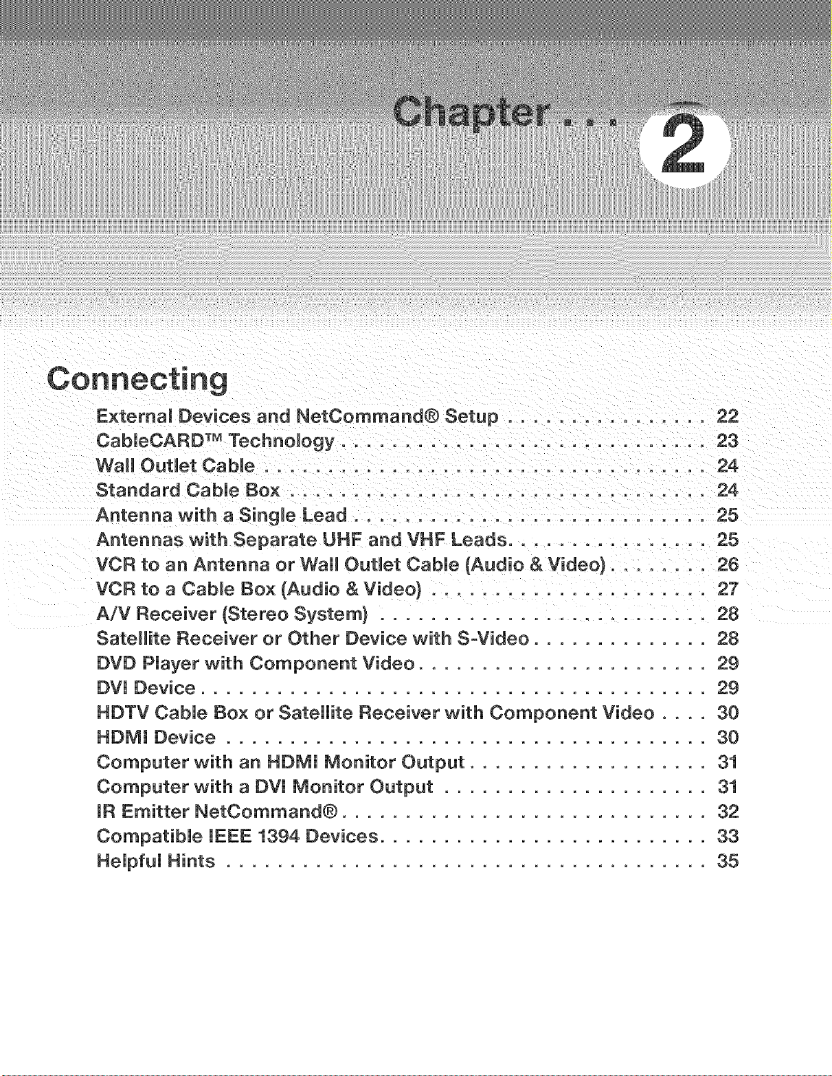
Connecting
E×temaU Devices and NetCommand® Setup ................ 22
CabieCARD TM TechnoUogy ............................. 23
WaUt OutUet CabUe ................................... 24
Standard Cable Box ................................. 24
Antenna with a Single Lead ............................ 25
Antennas with Separate UHF and VHF Leads ................ 25
VCR to an Antenna or Wall OutUet Cable (Audio & Video} ........ 26
VCR to a CabUe Box (Audio & Video} ...................... 27
A/V Receiver (Stereo System} .......................... 28
Satellite Receiver or Other Device with S-Video .............. 28
DVD PJayer with Component Video ....................... 2g
DVl Device ........................................ 2g
HDTV CabJe Box or Satellite Receiver with Component Video .... 30
HDMI Device ...................................... 30
Computer with an HDMI Monitor Output ................... 31
Computer with a DVI Monitor Output ..................... 31
IR Emitter NetCommand® ............................. 32
CompatibJe IEEE 1394 Devices .......................... 33
HeJpfuJ Hints ...................................... 35
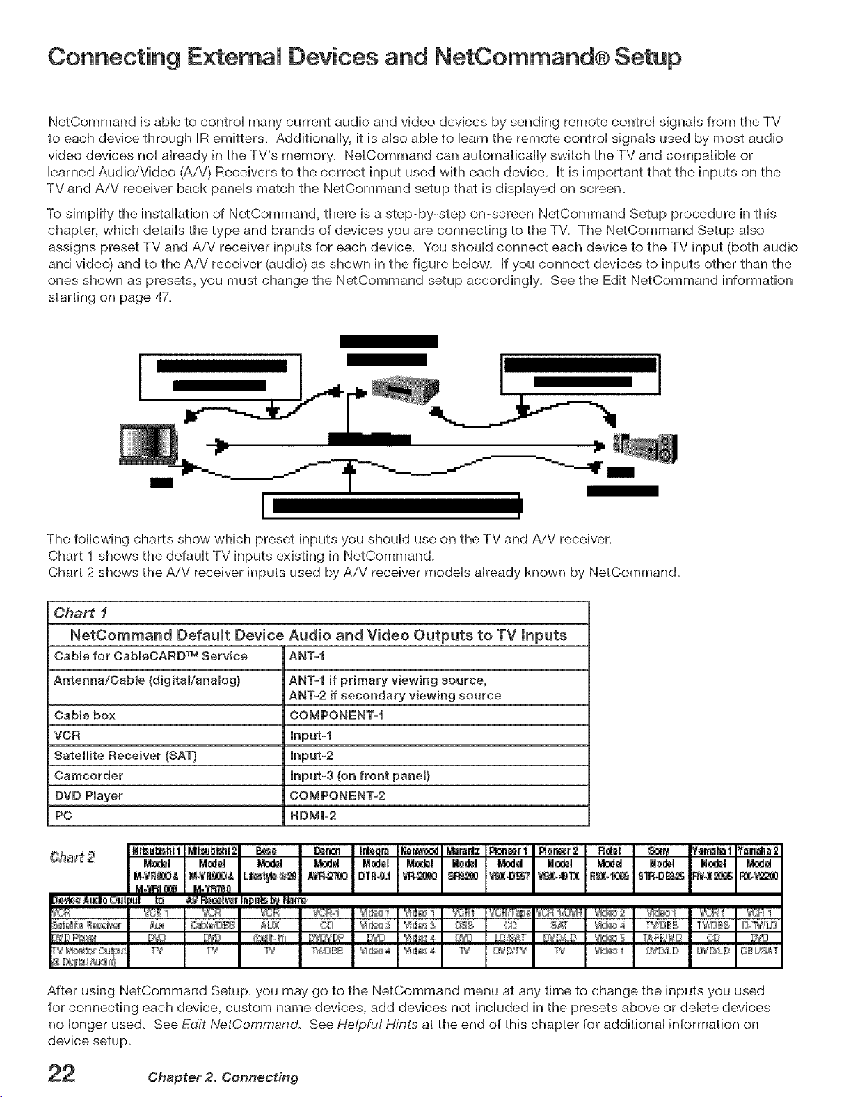
Connecting E×temai Devices and NetCommand® Setup
NetCommand is able to control many current audio and video devices by sending remote control signals from the TV
to each device through IR emitters. Additionally, it is also able to barn the remote control signals used by most audio
video devices not already in the TV's memory. NetCommand can automatically switch the TV and compatible or
learned Audio/'Video (A/V) Receivers to the correct input used with each device. It is important that the inputs on the
TV and AiV receiver back panels match the NetCommand setup that is displayed on screen.
To simplify the installation of NetCommand, there is a step-by-step on-screen NetCommand Setup procedure in this
chapter, which details the type and brands of devices you are connecting to the TV. The NetCommand Setup also
assigns preset TV and AiV receiver inputs for each device. You should connect each device to the TV input (both audio
and video) and to the AiV receiver (audio) as shown in the figure below. If you connect devices to inputs other than the
ones shown as presets, you must change the NetCommand setup accordingly. See the Edit NetCommand information
starting on page 47.
I
I I
The following charts show which preset inputs you should use on the TV and AiV receiver.
Chart 1 shows the default TV inputs existing in NetCommand.
Chart 2 shows the AiV receiver inputs used by AiV receiver models already known by NetCommand.
Chart 1
NetCommand Default Device Audio and Video Outputs to TV mnputs
Cable for CabmeCARD TM Service ANT=f
Antenna/Cable (digitaVanamog) ANT=I if primary viewing source,
ANT=2if secondary viewing source
Cable box COMPONENT=f
VCR lnput=f
Satellite Receiver (SAT) input-2
Camcorder input-3 (on front panel)
DVD Player COMPONENT=2
PC HDMI=2
After using NetCommand Setup, you may go to the NetCommand menu at any time to change the inputs you used
for connecting each device, custom name devices, add devices not included in the presets above or delete devices
no longer used. See Edit NetCommand. See He/pfu! Hints at the end of this chapter for additional information on
device setup.
Chapter 2. Connecting
CabieCARE) TM Technology
CabJeCARD TechnoJogy
CableCARD is a nationwide system standard that
allows your local cable TV provider to supply you with
an access card customized to your account. This card
allows your TV to receive, decode and unscramble the
premium digital channels included in your cable TV
subscription without the use of a cable box. It also
allows your cable provider to automatically update
and change your subscription. When you move to
a new cable provider's area, you simply return the
CableCARD to the original cable provider and get a
new card from your new cable provider.
Please note that CableCARD is a new technology and
your local cable provider may not currently be offering
this service. As time passes, this system will become
broadly supported by most cable providers.
The CableCARD system is "unidirectional" which
means your cable provider can send updates to the
access card and TV, however, the TV cannot send
back signals such as requests for Video-On-Demand
or Pay-pePView programs by remote control.
Digital cable channels authorized by the CableCARD
will be available on the Firewire® IEEE 1394 network
and can be shared by other products on the network.
Some digital channels or programs may not be copied
or recorded because of copy restriction limits set by
the content owners or copyright holders.
The digital television is capable of receiving analog
basic, digital basic and digital premium cable
television programming by direct connection to
a cable system providing such programming. A
security card (CableCARD) provided by your cable
operator is required to view encrypted digital
programming. Certain advanced and interactive
digital cable services such as video-on-demand, a
cable operator's enhanced program guide and data-
enhanced television services may require the use of a
set-top box. For more information call your local cable
operator.
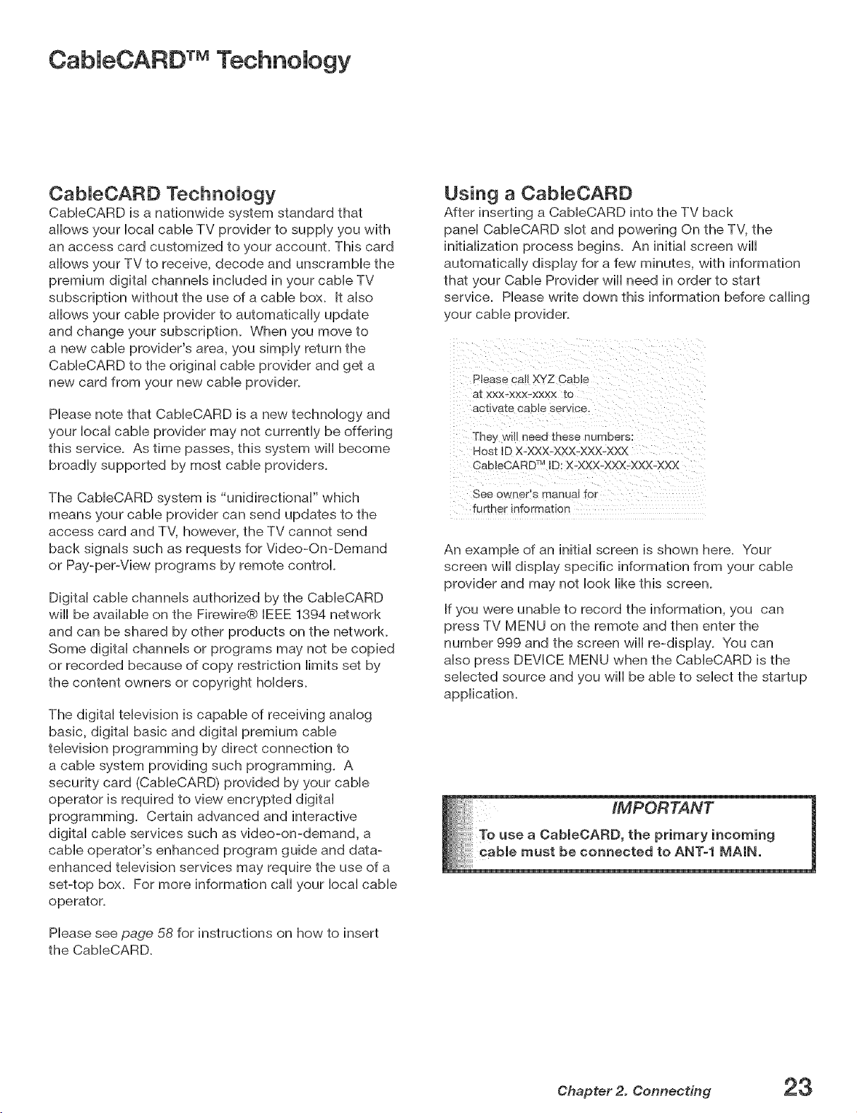
Using a CabJeCARD
After inserting a CableCARD into the TV back
panel CableCARD slot and powering On the TV, the
initialization process begins. An initial screen will
automatically display for a few minutes, with information
that your Cable Provider will need in order to start
service. Please write down this information before calling
your cable provider.
Please call XYZ Cable
at xxx-xxx-xxxx to
actwate caele service.
They wm neeo these numeers:
Host ID X-XXX-XXX-XXX-XXX
CableCARD 7MID: X-XXX-XXX-XXX-YOCX
See owner's manual for
further information
An example of an initial screen is shown here. Your
screen will display specific information from your cable
provider and may not look like this screen.
If you were unable to record the information, you can
press TV MENU on the remote and then enter the
number 999 and the screen will re-display. You can
also press DEVICE MENU when the CableCARD is the
selected source and you will be able to select the startup
application.
Please see page 58 for instructions on how to insert
the CableCARD.
Chapter 2. Connecting 23
Connecting a Wail Outlet Cable or Cable Box
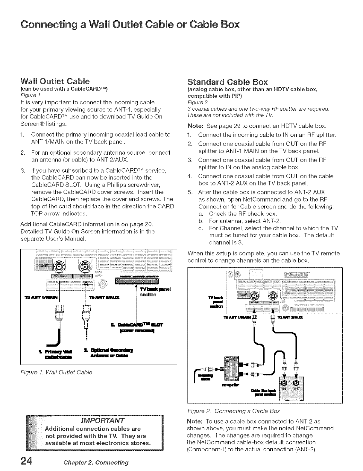
Wall OutJet CabJe
(can be used with a CabJeOARDTM)
Figure 1
It is very important to connect the incoming cabb
for your primary vbwing source to ANT-l, especially
for CabbCARD TM use and to downioad TV Guide On
Screen® iistings.
Connect the primary incoming coaxiai Headcabb to
ANT l/MAIN on the TV back panel.
2.
For an optional secondary antenna source, connect
an antenna (or cable) to ANT 2/AUX.
3.
If you have subscribed to a CableCARD TM service,
the CableCARD can now be inserted into the
CabieCARD SLOT. Using a Phillips screwdriver,
remove the CableCARD cover screws. Insert the
CableCARD, then replace the cover and screws. The
top of the card should face in the direction the CARD
TOP arrow indicates.
Additional CableCARD information is on page 20.
Detailed TV Guide On Screen information is in the
separate User's Manual.
Standard Cable Box
(analog cable box, other than an HDTV cable box,
compatiMe with PIP)
Figure 2
3 coaxial cables and one two-way RFsplitter arerequired,
Theseare not included with the T_/I
Note: See page 29 to connect an HDTV cable box.
1. Connect the incoming cable to IN on an RF splitter.
2. Connect one coaxial cable from OUT on the RF
splitter to ANT-1 MAIN on the TV back panel.
3. Connect one coaxial cable from OUT on the RF
splitter to IN on the analog cable box.
4. Connect one coaxial cable from OUT on the cable
box to ANT-2 AUX on the TV back panel.
5. After the cable box is connected to ANT-2 AUX
as shown, open NetCommand and go to the RF
Connection for Cable screen and do the following:
a. Check the RF check box.
b. For antenna, select ANT-2.
c. For Channel, select the channel to which the TV
must be tuned for your cable box. The default
channel is 3.
When this setup is complete, you can use the TV remote
control to change channels on the cable box.
I
T_T_
II I
II
Figure I. Waft Outlet Cable
Chapter 2. Connecting
III1_ i!111111_
J
n
roll
_m
Figure 2. Connecting a CaMe Box
Note: To use a cable box connected to ANT-2 as
shown above, you must make the noted NetCommand
changes. The changes are required to change
the NetCommand cable-box default connection
(Componentq) to the actual connection (ANT-2).
Connecting an Antenna with a Single Lead or Antennas with
Separate UHF and VHF Leads
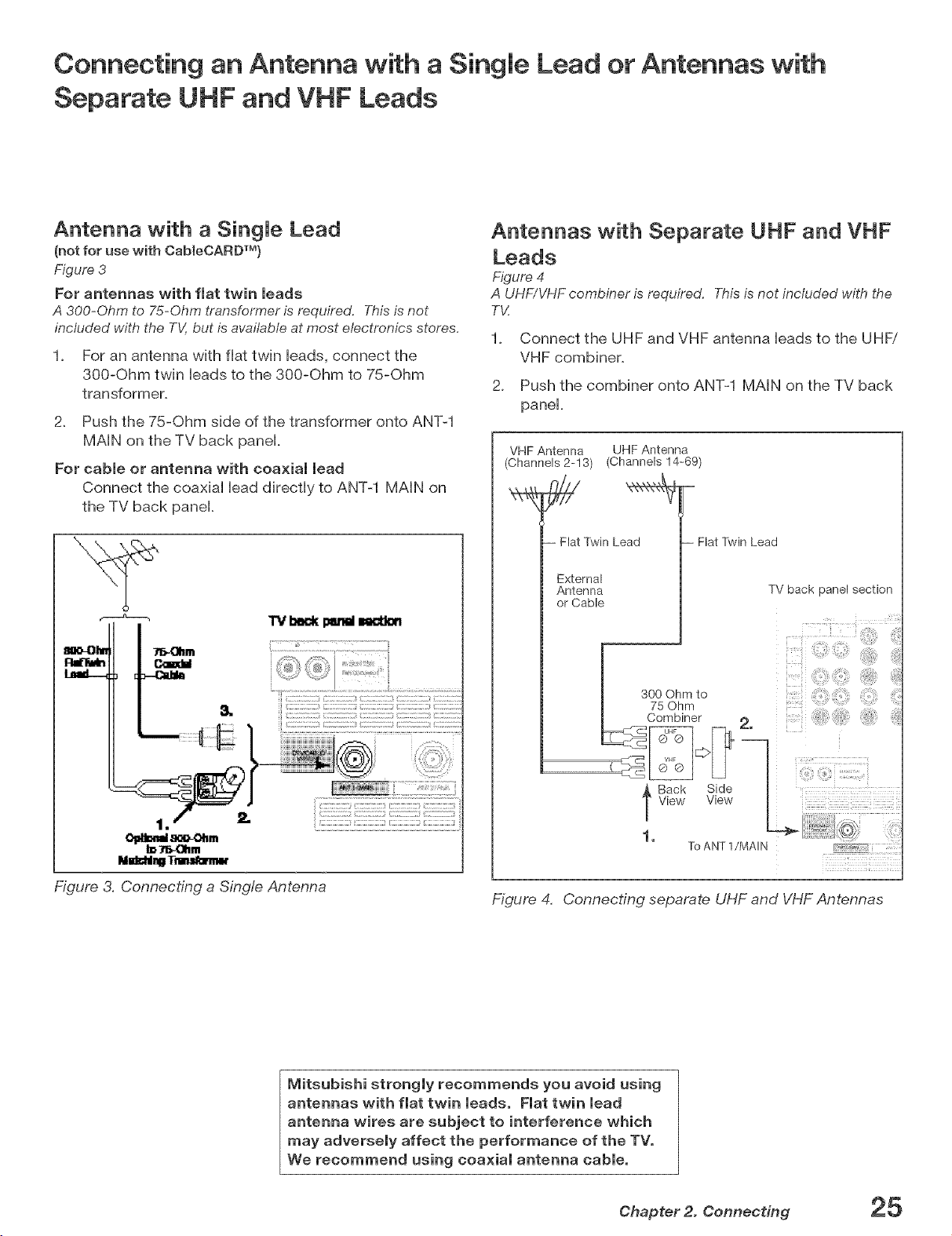
Antenna with a Single Lead
(notfor use with CabIeCARDTM}
Figure 3
For antennas with flat twin leads
A 300-Ohm to 75-Ohm transformeris required. Thisisnot
included with the TV,but is available at most electronics stores,
1. For an antenna with flat twin leads, connect the
300-Ohm twin leads to the 300-Ohm to 75-Ohm
transformer.
2. Push the 75-Ohm side of the transformer onto ANT-1
MAIN on the TV back panel.
For cable or antenna with coaxial lead
Connect the coaxial lead directly to ANT-1 MAIN on
the TV back panel.
TV I_ect(Ixltm N_n
81H,-OI_r "J_-_hm
Antennas with Separate UHF and VHF
Leads
Figure 4
A UHF/VHFcombiner is required, Thisis not included with the
T_:
1_ Connect the UHF and VHF antenna leads to the UHFi
VHF combiner,
2_ Push the combiner onto ANT-1 MAIN on the TV back
panel,
VHF Antenna UHF Antenna
(Channels 2-13) (Channels 14-69)
- Flat Twin Lead
External
Antenna
or Cable
-- Flat Twin Lead
TV back panel section
-7 TM -•n _
Figure 3. Connecting a Single Antenna
lVlitsubishi strongly recommends you avoid using
antennas with flat twin leads. Flat twin lead
antenna wires are subject to interference which
may adversely affect the performance of the TV.
We recommend using coaxial antenna cable.
00Ohmto :
I 75 Ohm
Combiner 2,
Back Side
.TView View
To ANT 1/MAIN
Figure 4, Connecting separate UHF and VHF Antennas
Chapter 2. Connecting 25
Connecting a VCR to an Antenna or Wail OutJet CabJe
Connecting VCR Audio and Video to the TV
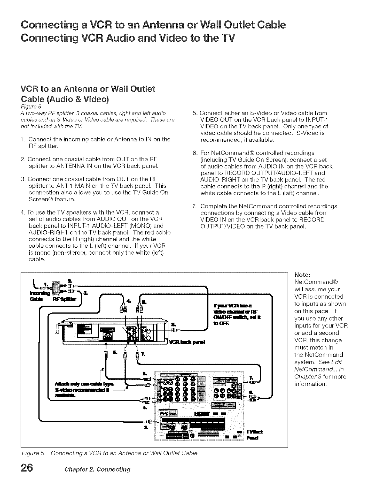
VCR to an Antenna or Wall OutJet
CabJe {Audio & Video)
Figure 5
5_
A two-way RF spfitter, 3 coaxial cables, right and left audio
cables and anS-Video or Videocable are required, These are
not included with the T_:
1. Connect the incoming cable or Antenna to IN on the
RF splitter.
2. Connect one coaxial cable from OUT on the RF
splitter to ANTENNA IN on the VCR back panel.
3. Connect one coaxial cable from OUT on the RF
splitter to ANT-1 MAIN on the TV back panel. This
connection also allows you to use the TV Guide On
Screen® feature.
4. To use the TV speakers with the VCR, connect a
set of audio cables from AUDIO OUT on the VCR
back panel to INPUT-1 AUDIO-LEFT (MONO) and
AUDIO-RIGHT on the TV back panel. The red cable
connects to the R (right) channel and the white
cable connects to the L (left) channel. If your VCR
is mono (non-stereo), connect only the white (left)
cable.
Connect either an S-Video or Video cable from
VIDEO OUT on the VCR back panel to INPUT-1
VIDEO on the TV back panel. Only one type of
video cable should be connected. S-Video is
recommended, if available.
6_
For NetCommand® controlled recordings
(including TV Guide On Screen), connect a set
of audio cables from AUDIO IN on the VCR back
panel to RECORD OUTPUT/AUDIO-LEFT and
AUDIO-RIGHT on the TV back panel. The red
cable connects to the R (right) channel and the
white cable connects to the L (left) channel.
7_
Complete the NetCommand controlled recordings
connections by connecting a Video cable from
VIDEO IN on the VCR back panel to RECORD
OUTPUT/VIDEO on the TV back panel.
"rl/IJ:ik
Note:
NetCommand®
will assume your
VCR is connected
to inputs as shown
on this page. If
you use any other
inputs for your VCR
or add a second
VCR, this change
must match in
the NetCommand
system. See Edit
NetCommand... in
Chapter 3 for more
information.
Figure 5. Connecting a VCR to an Antenna or Wail Outlet Cable
26 Chapter 2. Connecting
Connecting a VCR to a CabJe Box (Audio & Video)
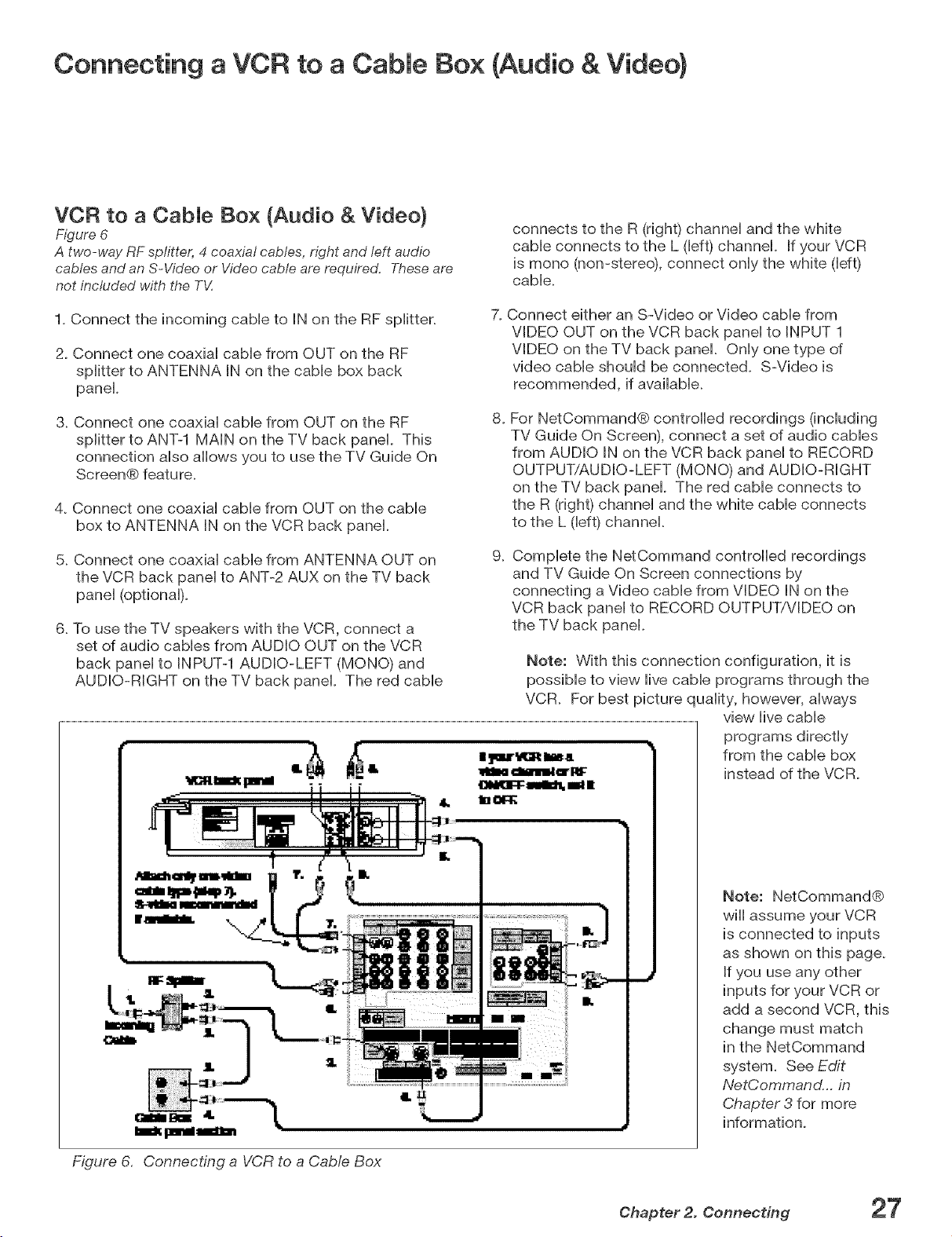
VCR to a Cable Box (Audio & Video)
Figure 6
A two-way RF splitter, 4 coaxial cables, n_Thtand left audio
cables and anS-Video or Video cable are required, Theseare
not included with the TV,
1. Connect the incoming cable to IN on the RF splitter.
2. Connect one coaxial cable from OUT on the RF
splitter to ANTENNA IN on the cable box back
panel
3. Connect one coaxial cable from OUT on the RF
splitter to ANT-1 MAIN on the TV back panel. This
connection also allows you to use the TV Guide On
Screen@ feature.
4. Connect one coaxial cable from OUT on the cable
box to ANTENNA IN on the VCR back panel.
5. Connect one coaxial cable from ANTENNA OUT on
the VCR back panel to ANT-2 AUX on the TV back
panel (optional).
6. To use the TV speakers with the VCR, connect a
set of audio cables from AUDIO OUT on the VCR
back panel to INPUT-1 AUDIO-LEFT (MONO) and
AUDIO-RIGHT on the TV back panel The red cable
connects to the R (right) channel and the white
cable connects to the L (left) channel. If your VCR
is mono (non-stereo), connect only the white ([eft)
cable.
7. Connect either an S-Video or Video came from
VIDEO OUT on the VCR back panel to INPUT 1
VIDEO on the TV back panel. Only one type of
video cable should be connected. S-Video is
recommended, if available.
8_
For NetCommand@ controlled recordings (including
TV Guide On Screen), connect a set of audio cables
from AUDIO IN on the VCR back panel to RECORD
OUTPUT/AUDIO-LEFT (MONO) and AUDIO-RIGHT
on the TV back panel The red cable connects to
the R (right) channel and the white cable connects
to the L (left) channel.
g_
Complete the NetCommand controlled recordings
and TV Guide On Screen connections by
connecting a Video cable from VIDEO IN on the
VCR back panel to RECORD OUTPUT/VIDEO on
the TV back panel.
Note: With this connection configuration, it is
possible to view live cable programs through the
VCR. For best picture quality, however, always
view live cable
programs directly
from the cable box
instead of the VCR.
Figure 6. Connecting a VCR to a CaMe Box
Note: NetCommand@
wiii assume your VCR
is connected to inputs
as shown on this page.
If you use any other
inputs for your VCR or
add a second VCR, this
change must match
in the NetCommand
system. See Edit
NetCommand.., in
Chapter 3 for more
information.
Chapter 2. Connecting 27
Connecting an A/V Receiver (Stereo System}
Connecting a Satellite Receiver or Other Device with S -Video
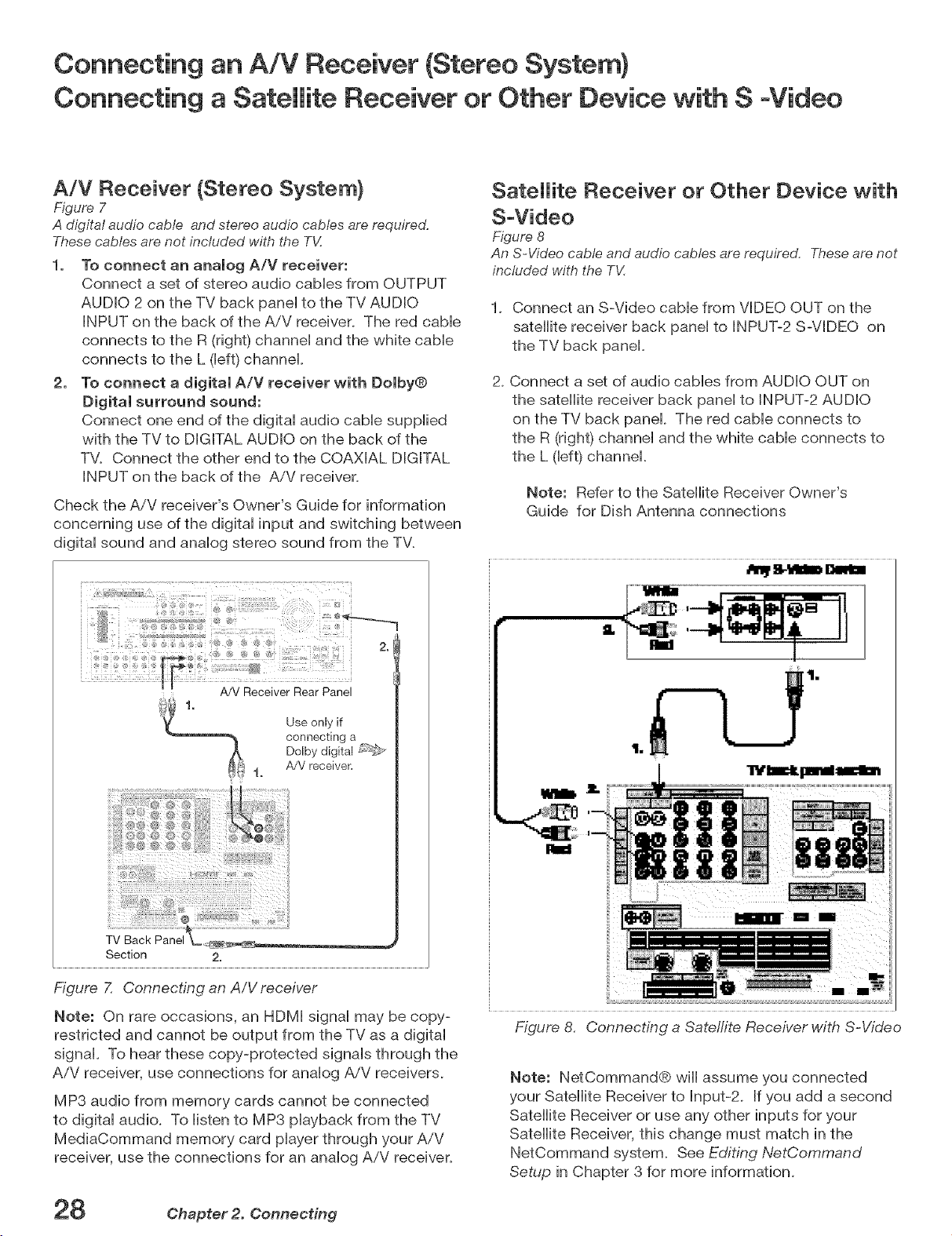
A/V Receiver (Stereo System}
Figure 7
A digital audio cable and stereo audio cables are required.
These cables are not included with the TV.
1, To connect an analog A/V receiver:
Connect a set of stereo audio caMes from OUTPUT
AUDIO 2 on the TV back paneHto the TV AUDIO
INPUT on the back of the AiV receiver. The red cabHe
connects to the R (right) channeH and the white cabHe
connects to the L (Heft)channel
2. To connect a digital A/V receiver with Dolby®
Digital surround sound:
Connect one end of the digitaH audio cabHesuppHied
with the TV to DIGITAL AUDIO on the back of the
TV. Connect the other end to the COAXIAL DIGITAL
INPUT on the back of the AiV receiver.
Check the A/V receiver's Owner's Guide for information
concerning use of the digital input and switching between
digital sound and analog stereo sound from the TV.
Satellite Receiver or Other Device with
S-Video
Figure 8
An S-Video cable and audio cables are required. Theseare not
included with the T_I
1_ Connect an S-Video cable from VIDEO OUT on the
satellite receiver back panel to INPUT-2 S-VIDEO on
the TV back panel.
2_Connect a set of audio cables from AUDIO OUT on
the satellite receiver back panel to INPUT-2 AUDIO
on the TV back panel The red cable connects to
the R (right) channel and the white cable connects to
the L (left) channel.
Note: Refer to the Satellite Receiver Owner's
Guide for Dish Antenna connections
A/V Receiver Rear Panel
Use only if
connecting a
Dolby digital F_';_
A/V receiver=
t.
Section 2.
Figure 7. Connecting an A/V receiver
Note: On rare occasions, an HDMI signal may be copy-
restricted and cannot be output from the TV as a digital
signal. To hear these copy-protected signals through the
AiV receiver, use connections for analog AiV receivers.
MP3 audio from memory cards cannot be connected
to digital audio. To listen to MP3 playback from the TV
MediaCommand memory card player through your A/V
receiver, use the connections for an analog AiV receiver.
iii!
iiii_
Figure 8.
Note: NetCommand® will assume you connected
your Satellite Receiver to Input-2. Ifyou add a second
Satellite Receiver or use any other inputs for your
Satellite Receiver, this change must match in the
NetCommand system. See Editing NetCommand
Setup in Chapter 3 for more information.
Connecting a Sate!rite Receiver with S-Video
Chapter 2. Connecting
Connecting a DVD Pmayerwith Component Video
Connecting a DVl Device
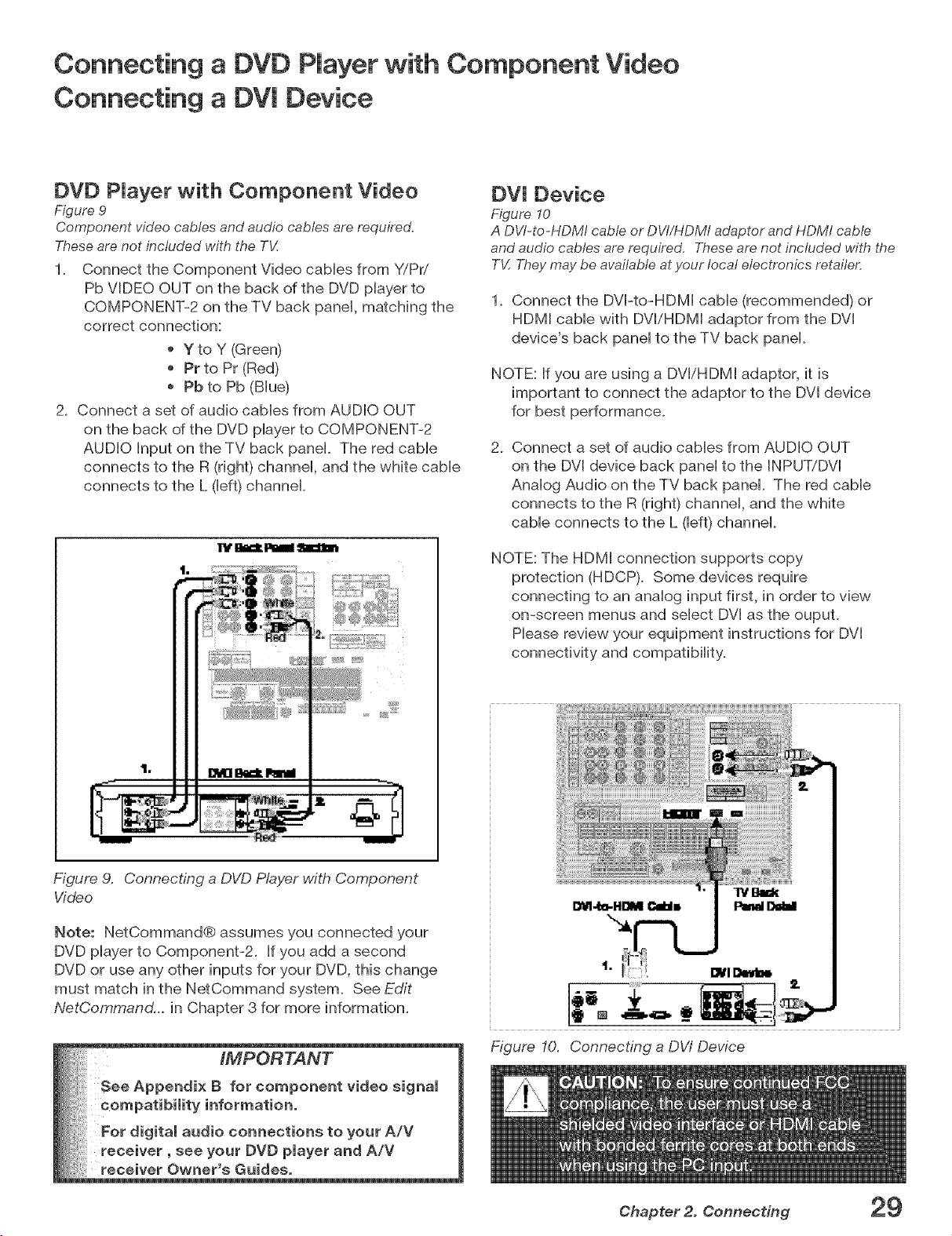
DVD PJayer with Component Video
Figure 9
Component video cables and audio cables are required,
Theseare not included with the TV,
1_ Connect the Component Video cabHes from Y/Pd
Pb VIDEO OUT on the back of the DVD pHayerto
COMPONENT-2 on the TV back panel matching the
correct connection:
Y to Y (Green)
Pr to Pr (Red)
Pb to Pb (BHue)
2_ Connect a set of audio cabHesfrom AUDIO OUT
on the back of the DVD pHayerto COMPONENT-2
AUDIO Input on the TV back panel The red came
connects to the R (right) channeH, and the white came
connects to the L (Heft)channel
DVl Device
Figure 10
A DV/-to-HDMI cable or DVI/HDMI adaptor and HDM/cable
and audio cables are required, Theseare not included with the
TV,Theymay be available at your local electronics retailer,
1. Connect the DVI-to-HDMI cabHe(recommended) or
HDMI cabHewith DVliHDMI adaptor from the DVI
device's back panel to the TV back panel.
NOTE: If you are using a DVI/HDMI adaptor, it is
important to connect the adaptor to the DVI device
for best performance.
2. Connect a set of audio cables from AUDIO OUT
on the DVI device back panel to the INPUT/DVI
Analog Audio on the TV back panel. The red cable
connects to the R (right) channel, and the white
cable connects to the L (left) channel.
NOTE: The HDMI connection supports copy
protection (HDCP). Some devices require
connecting to an analog input first, in order to view
on-screen menus and select DVI as the ouput.
Please review your equipment instructions for DVI
connectivity and compatibility.
Figure 9. Connecting a DVD Player with Component
Video
Note: NetCommand® assumes you connected your
DVD pHayerto Component-2. If you add a second
DVD or use any other inputs for your DVD, this change
must match in the NetCommand system. See Edit
NetCommand... in Chapter 3 for more information.
Figure 10. Connecting a DW Device
Chapter 2. Connecting 29
Connecting an HDTV Cable Box or Satellite Receiver with
Component Video
Connecting an HDMI Device
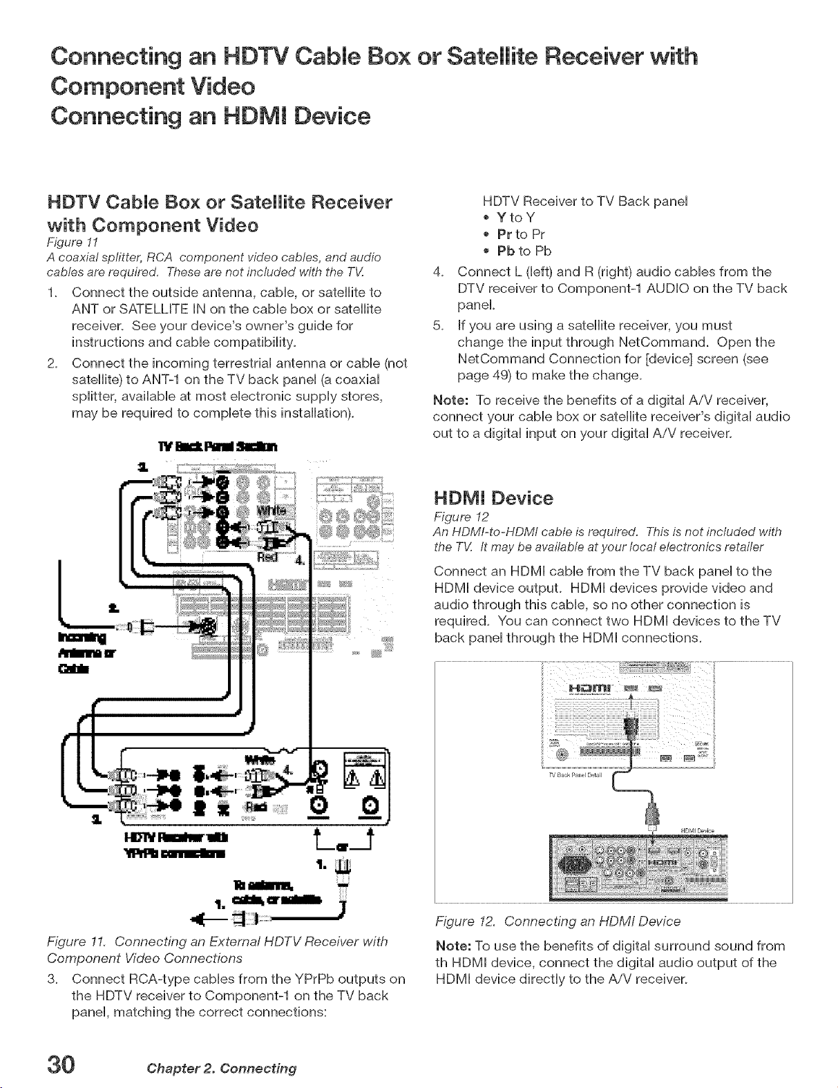
HDTV CabJe Box or Satellite Receiver
with Component Video
Figure 11
A coaxial spfitter, RCA component video cables, and audio
cables are required, These are not included with the T_/:
1. Connect the outside antenna, cabHe,or satellite to
ANT or SATELLITE IN on the came box or satellite
receiver. See your device's owner's guide for
instructions and cabHecompatibiHity.
2. Connect the incoming terrestrial antenna or cable (not
satellite) to ANT-1 on the TV back panel (a coaxial
splitter, available at most electronic supply stores,
may be required to complete this installation).
HDTV Receiver to TV Back panel
YtoY
Pr to Pr
Pb to Pb
4_
Connect L (left) and R (right) audio cables from the
DTV receiver to Component-1 AUDIO on the TV back
panel.
5_
If you are using a satellite receiver, you must
change the input through NetCommand. Open the
NetCommand Connection for [device] screen (see
page 49) to make the change.
Note: To receive the benefits of a digital A/V receiver,
connect your cable box or satellite receiver's digital audio
out to a digital input on your digital AiV receiver.
HDMI Device
Figure 12
An HDMI-to-HDMI cable is required. This is not included with
the TV. /t maybe available at your local electronics retailer
Connect an HDMI cable from the TV back panel to the
HDMI device output. HDMI devices provide video and
audio through this cable, so no other connection is
required. You can connect two HDMI devices to the TV
back panel through the HDMI connections.
"_llllb cmrE_!
Figure 11. Connecting an External HDTV Receiver with
Component Video Connections
3. Connect RCA-type cables from the YPrPb outputs on
the HDTV receiver to Component-1 on the TV back
panel, matching the correct connections:
30 Chapter 2. Connecting
..... ............................................. i
Figure 12. Connecting an HDM/ Device
Note: To use the benefits of digital surround sound from
th HDMI device, connect the digital audio output of the
HDMI device directly to the AiV receiver.
 Loading...