

Page 1

Projection Television Models
TM
TM
TM
WD-52627, WD-62627
Owner’s Guide
TV Information:
Use this space to record the model and serial numbers of
your television. This information is on the back of your TV
Model number
Serial number
visit our website at
www.mitsubishi-tv.com
Page 2
CAUTION
RISK OF ELECTRIC SHOCK
DO NOT OPEN
CAUTION: TO REDUCE THE RISK OF ELECTRIC SHOCK, DO NOT REMOVE COVER (OR
BACK). NO USER SERVICEABLE PARTS INSIDE. REFER SERVICING TO QUALIFIED SERVICE
PERSONNEL.
The lightning flash with arrowhead symbol within an equilateral triangle is intended to alert the user of
the presence of uninsulated “dangerous voltage” within the product’s enclosure that may be sufficient
magnitude to constitute a risk of electric shock.
The exclamation point within an equilateral triangle is intended to alert the user to the presence of
important operating and maintenance (servicing) instructions in the literature accompanying the appliance.
This TV is heavy! Exercise extreme care when lifting or moving. Lifting or moving the TV requires a
minimum of two adults. To prevent damage to your TV, your TV should not be jarred or moved while it is
turned on. Power off your TV before moving it.
Portions of the advanced circuitry of this TV must continue to operate even when the TV is turned off.
Some of these circuits therefore need to be cooled at all times. A low power standby fan may be heard in
a quiet environment. This is normal operation.
Custom cabinet installation must allow for proper air circulation around the television.
TV Guide On Screen® Access Requirements
TV Guide On Screen listings are not provided by Mitsubishi Digital Electronics America, Inc. Operation of TV Guide
On Screen requires over-the-air or cable access to stations carrying TV Guide On Screen program listings. If listings
are not available in your area or become discontinued by the local provider, TV Guide On Screen will not operate. TV
Guide On Screen does not provide program listings for satellite TV systems.
Stand Requirement
CAUTION: Mitsubishi TV model WD-52627 is for use only with Mitsubishi stand model MB-52527. Mitsubishi TV
model WD-62627 is for use only with Mitsubishi stand model MB-62527. Use with other stands is capable of resulting
in instability causing possible injury.
Lamp Replacement
The image on this TV is produced by a high-brightness lamp that will operate for many hours. Eventually, however, this
lamp will need to be replaced. It is designed to be easily replaced by the TV owner. Front panel indicators and/or onscreen messages will assist you in determining when the lamp needs to be replaced. Please see Appendix H for details
on lamp replacement.
To order a new lamp:
While Under Warranty After Warranty
Call (800) 332-2119. Please have model number, serial
number, and TV purchase date available.
Call (800) 553-7278. Order lamp part number
915P026010.
WARNING: TO REDUCE THE RISK OF FIRE OR ELECTRIC SHOCK, DO NOT EXPOSE THIS APPLIANCE TO RAIN OR
MOISTURE.
CAUTION: TO PREVENT ELECTRIC SHOCK, MATCH WIDE BLADE OF PLUG TO WIDE SLOT, FULLY INSERT.
NOTE TO CATV SYSTEM INSTALLER: THIS REMINDER IS PROVIDED TO CALL THE CATV SYSTEM INSTALLER’S
ATTENTION TO ARTICLE 820-40 OF THE NEC THAT PROVIDES GUIDELINES FOR THE PROPER GROUNDING AND,
IN PARTICULAR, SPECIFIES THAT THE CABLE GROUND SHALL BE CONNECTED TO THE GROUNDING SYSTEM OF
THE BUILDING, AS CLOSE TO THE POINT OF CABLE ENTRY AS PRACTICAL.
Page 3

FCC Declaration of Conformity
Product: Projection Television Receiver
Models: WD-52627, WD-62627
Responsible Party: Mitsubishi Digital Electronics America, Inc.
9351 Jeronimo Road
Irvine, CA 92618-1904
Telephone: 949-465-6000
This device complies with Part 15 of the FCC Rules. Operation is subject to the following two conditions:
(1) This device may not cause harmful interference, and
(2) this device must accept any interference received, including interference that may cause undesired operation.
Note: This equipment has been tested and found to comply with the limits for a Class B digital device, pursuant to
part 15 of the FCC Rules. These limits are designed to provide reasonable protection against harmful interference in
a residential installation. This equipment generates, uses and can radiate radio frequency energy and, if not installed
and used in accordance with the instructions, may cause harmful interference to radio communications. However,
there is no guarantee that interference will not occur in a particular installation. If this equipment does cause harmful
interference to radio or television reception, which can be determined by turning the equipment off and on, the user
is encouraged to try to correct the interference by one or more of the following measures:
• Reorient or relocate the receiving antenna.
• Increase the separation between the equipment and the receiver.
• Connect the equipment into an outlet on a circuit different from that to which the receiver is connected.
• Consult the dealer or an experienced radio/TV technician for help.
CAUTION: To ensure continued FCC compliance, the user must use a shielded video interface
or HDMI cable with bonded ferrite cores at both ends when using the PC input.
Changes or modifications not expressly approved by Mitsubishi could cause harmful interference and would
void the user’s authority to operate this equipment.
Page 4

IMPORTANT SAFEGUARDS
Please read the following safeguards for your TV and retain for future reference. Always follow all
warnings and instructions marked on the television.
1. Read, Retain and Follow All Instructions
Read all safety and operating instructions before operating the TV. Retain the safety and operating instructions
for future reference. Follow all operating and use instructions.
2. Heed Warnings
Adhere to all warnings on the appliance and in the operating instructions.
3. Cleaning
Unplug the TV from the wall outlet before cleaning. Do not use liquid, abrasive or aerosol cleaners. Cleaners can
permanently damage the cabinet and screen. Use a lightly dampened cloth for cleaning.
4. Attachments and Equipment
Never add any attachments and/or equipment without approval of the manufacturer as such additions may result
in the risk of fire, electric shock or other personal injury.
5. Water and Moisture
Do not use the TV where contact with or immersion in water is possible. Do not use near bath tubs, wash bowls,
kitchen sinks, laundry tubs, swimming pools, etc.
6. Accessories
Do not place the TV on an unstable cart, stand, tripod, or table. The TV may fall, causing
serious injury to a child or adult and serious damage to the TV. Use only with a cart, stand,
tripod, bracket or table recommended by the manufacturer, or sold with the TV. Any mounting
of the TV should follow the manufacturer’s instructions, and should use mounting accessories
recommended by the manufacturer.
An appliance and cart combination should be moved with care. Quick stops, excessive force,
and uneven surfaces may cause the appliance and cart combination to overturn.
7. Ventilation
Slots and openings in the cabinet are provided for ventilation and to ensure reliable operation of the TV and to
protect it from overheating. Do not block these openings or allow them to be obstructed by placing the TV on a
bed, sofa, rug, or other similar surface. Nor should it be placed over a radiator or heat register. If the TV is to be
placed in a rack or bookcase, ensure that there is adequate ventilation and that the manufacturer’s instructions
have been adhered to.
8. Power Source
This TV should be operated only from the type of power source indicated on the marking label. If you are not sure
of the type of power supplied to your home, consult your appliance dealer or local power company.
9. Grounding or Polarization
This TV is equipped with a polarized alternating current line plug having one blade wider than the other. This plug
will fit into the power outlet only one way. If you are unable to insert the plug fully into the outlet, try reversing the
plug. If the plug should still fail to fit, contact your electrician to replace your obsolete outlet. Do not defeat the
safety purpose of the polarized plug.
10. Power-Cord Protection
Power-supply cords should be routed so that they are not likely to be walked on or pinched by items placed
upon or against them, paying particular attention to cords at plugs, convenience receptacles, and the point
where they exit from the TV.
11. Lightning
For added protection for this TV during a lightning storm, or when it is left unattended and unused for long
period of time, unplug it from the wall outlet and disconnect the antenna or cable system. This will prevent
damage to the TV due to lightning and power-line surges.
4
Page 5
IMPORTANT SAFEGUARDS, continued
ANT E NN A
LE AD I N W IR E
ANT E NN A
DIS C HA R GE UN IT
(NE C AR T IC LE 810-2 0)
G R O UN DIN G
C OND UC TO R S
(NE C AR T IC LE 810-2 1)
G R O UN D C L AMP S
P OW ER S E R VI CE G R OU NDIN G
E LE C TR O DE S YS T E M
(NE C AR T 25 0, P AR T H)
G R O UN D C L AMP
E LE C TR I C
S E R VIC E
E QU IP ME NT
NE C — NA TIO NA L E L E CT R IC AL C O DE
E X AMP L E O F A NT E N NA G R OU ND ING
12. Power Lines
An outside antenna system should not be located in the vicinity of overhead power lines or other electric light or
power circuits, or where it can fall into such power lines or circuits. When installing an outside antenna system,
extreme care should be taken to keep from touching such power lines or circuits as contact with them might be
fatal.
13. Overloading
Do not overload wall outlets and extension cords as this can result in a risk of fire or electric shock.
14. Object and Liquid Entry
Never push objects of any kind into this TV through openings as they may touch dangerous voltage points or shortout parts that could result in fire or electric shock. Never spill liquid of any kind on or into the TV.
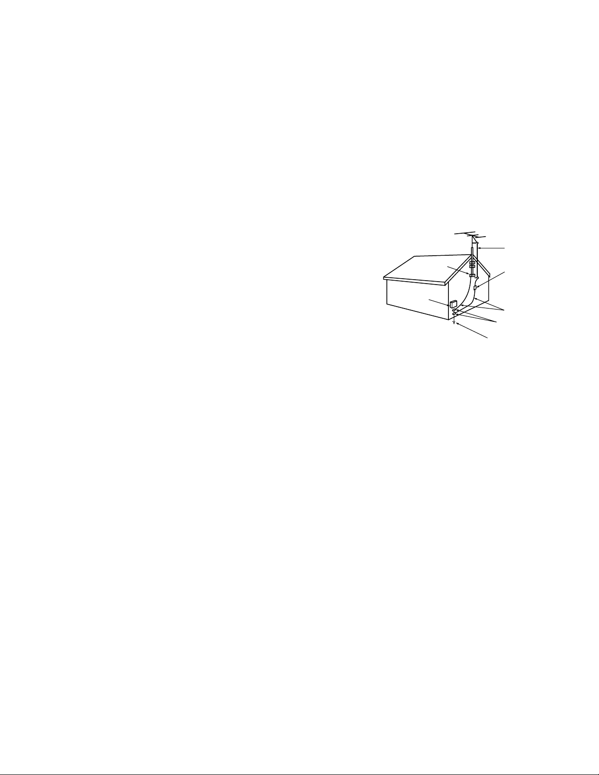
15. Outdoor Antenna Grounding
If an outside antenna or cable system is connected to the TV, be sure the
antenna or cable system is grounded so as to provide some protection
against voltage surges and built-up static charges.
Article 810 of the National Electric Code, ANSI/NFPA No. 70-2002,
provides information with respect to proper grounding of the mast
and supporting structure, grounding of the lead in wire to an antenna
discharge unit, size of grounding conductors, location of antenna
discharge unit, connection to grounding electrodes, and requirements
for the grounding electrode.
16. Servicing
Do not attempt to service this TV yourself as opening or removing covers may expose you to dangerous voltage
or other hazards. Refer all servicing to qualified service personnel.
17. Damage Requiring Service
Unplug the TV from the wall outlet and refer servicing to qualified service personnel under the following
conditions:
(a) When the power-supply cord or plug is damaged.
(b) If liquid has been spilled, or objects have fallen into the TV.
(c) If the TV has been exposed to rain or water.
(d) If the TV does not operate normally by following the operating instructions, adjust only those controls that are
covered by the operating instructions as an improper adjustment of other controls may result in damage and
will often require extensive work by a qualified technician to restore the TV to its normal operation.
(e) If the TV has been dropped or the cabinet has been damaged.
(f) When the TV exhibits a distinct change in performance - this indicates a need for service.
18. Replacement Parts
When replacement parts are required, be sure the service technician has used replacement parts specified by the
manufacturer or have the same characteristics as the original part. Unauthorized substitutions may result in fire,
electric shock or other hazards.
19. Safety Check
Upon completion of any service or repair to the TV, ask the service technician to perform safety checks to determine
that the TV is in safe operating condition.
20. Heat
The product should be situated away from heat sources such as radiators, heat registers, stoves or other products
5
(including amplifiers) that produce heat.
Page 6

Contents
Chapter 1: Television Overview
TV Accessories . . . . . . . . . . . . . . . . . . . . . . . . . . . . . . . . . . . . . . . . . . . . . . . . . . . . . . . . . . . . . . . . . . . . . 10
Special Features . . . . . . . . . . . . . . . . . . . . . . . . . . . . . . . . . . . . . . . . . . . . . . . . . . . . . . . . . . . . . . . . . . . . 11
Front Control Panel . . . . . . . . . . . . . . . . . . . . . . . . . . . . . . . . . . . . . . . . . . . . . . . . . . . . . . . . . . . . . . . . . 12
Remote Control
Overview . . . . . . . . . . . . . . . . . . . . . . . . . . . . . . . . . . . . . . . . . . . . . . . . . . . . . . . . . . . . . . . . . . . . . . . 14
Battery Installation . . . . . . . . . . . . . . . . . . . . . . . . . . . . . . . . . . . . . . . . . . . . . . . . . . . . . . . . . . . . . . 15
Care . . . . . . . . . . . . . . . . . . . . . . . . . . . . . . . . . . . . . . . . . . . . . . . . . . . . . . . . . . . . . . . . . . . . . . . . . . . 15
Sleep Timer . . . . . . . . . . . . . . . . . . . . . . . . . . . . . . . . . . . . . . . . . . . . . . . . . . . . . . . . . . . . . . . . . . . . . 15
TV Back Panel . . . . . . . . . . . . . . . . . . . . . . . . . . . . . . . . . . . . . . . . . . . . . . . . . . . . . . . . . . . . . . . . . . . . . . 16
Media Card Slots . . . . . . . . . . . . . . . . . . . . . . . . . . . . . . . . . . . . . . . . . . . . . . . . . . . . . . . . . . . . . . . . . . . 18
Front-Panel Input 3 . . . . . . . . . . . . . . . . . . . . . . . . . . . . . . . . . . . . . . . . . . . . . . . . . . . . . . . . . . . . . . . . . . 18
Using the System Reset Button . . . . . . . . . . . . . . . . . . . . . . . . . . . . . . . . . . . . . . . . . . . . . . . . . . . . . . . 19
Using the Reset Menu to Reset the TV . . . . . . . . . . . . . . . . . . . . . . . . . . . . . . . . . . . . . . . . . . . . . . . . 19
Chapter 2: Connecting
External Devices and NetCommand® Setup . . . . . . . . . . . . . . . . . . . . . . . . . . . . . . . . . . . . . . . . . . . 22
CableCARD™ Technology . . . . . . . . . . . . . . . . . . . . . . . . . . . . . . . . . . . . . . . . . . . . . . . . . . . . . . . . . . . 23
Wall Outlet Cable . . . . . . . . . . . . . . . . . . . . . . . . . . . . . . . . . . . . . . . . . . . . . . . . . . . . . . . . . . . . . . . . . . . 24
Standard Cable Box . . . . . . . . . . . . . . . . . . . . . . . . . . . . . . . . . . . . . . . . . . . . . . . . . . . . . . . . . . . . . . . . . 24
Antenna with a Single Lead . . . . . . . . . . . . . . . . . . . . . . . . . . . . . . . . . . . . . . . . . . . . . . . . . . . . . . . . . . 25
Antennas with Separate UHF and VHF Leads . . . . . . . . . . . . . . . . . . . . . . . . . . . . . . . . . . . . . . . . . . 25
VCR to an Antenna or Wall Outlet Cable (Audio & Video) . . . . . . . . . . . . . . . . . . . . . . . . . . . . . . . . . 26
VCR to a Cable Box (Audio & Video) . . . . . . . . . . . . . . . . . . . . . . . . . . . . . . . . . . . . . . . . . . . . . . . . . . . 27
A/V Receiver (Stereo System) . . . . . . . . . . . . . . . . . . . . . . . . . . . . . . . . . . . . . . . . . . . . . . . . . . . . . . . . 28
Satellite Receiver or Other Device with S-Video . . . . . . . . . . . . . . . . . . . . . . . . . . . . . . . . . . . . . . . . 28
DVD Player with Component Video . . . . . . . . . . . . . . . . . . . . . . . . . . . . . . . . . . . . . . . . . . . . . . . . . . . 29
DVI Device . . . . . . . . . . . . . . . . . . . . . . . . . . . . . . . . . . . . . . . . . . . . . . . . . . . . . . . . . . . . . . . . . . . . . . . . . 29
HDTV Cable Box or Satellite Receiver with Component Video . . . . . . . . . . . . . . . . . . . . . . . . . . . 30
HDMI Device . . . . . . . . . . . . . . . . . . . . . . . . . . . . . . . . . . . . . . . . . . . . . . . . . . . . . . . . . . . . . . . . . . . . . . . 30
Computer with an HDMI Monitor Output . . . . . . . . . . . . . . . . . . . . . . . . . . . . . . . . . . . . . . . . . . . . . . . 31
Computer with a DVI Monitor Output . . . . . . . . . . . . . . . . . . . . . . . . . . . . . . . . . . . . . . . . . . . . . . . . . . 31
IR Emitter NetCommand® . . . . . . . . . . . . . . . . . . . . . . . . . . . . . . . . . . . . . . . . . . . . . . . . . . . . . . . . . . . 32
Compatible IEEE 1394 Devices . . . . . . . . . . . . . . . . . . . . . . . . . . . . . . . . . . . . . . . . . . . . . . . . . . . . . . . 33
Helpful Hints . . . . . . . . . . . . . . . . . . . . . . . . . . . . . . . . . . . . . . . . . . . . . . . . . . . . . . . . . . . . . . . . . . . . . . . 35
Chapter 3: NetCommand® Setup and Editing
NetCommand® Introduction . . . . . . . . . . . . . . . . . . . . . . . . . . . . . . . . . . . . . . . . . . . . . . . . . . . . . . . . . 38
Using the Remote Control with NetCommand® . . . . . . . . . . . . . . . . . . . . . . . . . . . . . . . . . . . . . . . . 39
NetCommand® Setup On-Screen Buttons . . . . . . . . . . . . . . . . . . . . . . . . . . . . . . . . . . . . . . . . . . . . . 40
3D Graphical Menu System . . . . . . . . . . . . . . . . . . . . . . . . . . . . . . . . . . . . . . . . . . . . . . . . . . . 41
NetCommand® Initial Setup . . . . . . . . . . . . . . . . . . . . . . . . . . . . . . . . . . . . . . . . . . . . . . . . . . . . . . . . . 42
Edit NetCommand®: Add an A/V Receiver . . . . . . . . . . . . . . . . . . . . . . . . . . . . . . . . . . . . . . . . . . . . 45
Edit NetCommand®: Add Devices . . . . . . . . . . . . . . . . . . . . . . . . . . . . . . . . . . . . . . . . . . . . . . . . . . . 48
Edit NetCommand®: Change or Delete Devices . . . . . . . . . . . . . . . . . . . . . . . . . . . . . . . . . . . . . . . 52
Page 7

Chapter 4: IEEE 1394 Devices and NetCommand®-Controlled Recordings
IEEE 1394 Devices and NetCommand® Control . . . . . . . . . . . . . . . . . . . . . . . . . . . . . . . . . . . . . . . . 54
Adding IEEE 1394 Devices Automatically . . . . . . . . . . . . . . . . . . . . . . . . . . . . . . . . . . . . . . . . . . . . . . 55
Device Selection Menu . . . . . . . . . . . . . . . . . . . . . . . . . . . . . . . . . . . . . . . . . . . . . . . . . . . . . . . . . . . . . . 57
Using the Device Menu Button to Display Menus . . . . . . . . . . . . . . . . . . . . . . . . . . . . . . . . . . . . . . . 58
Using the GUIDE Button to Display ChannelView™ and Menus . . . . . . . . . . . . . . . . . . . . . . . . . . 59
NetCommand®-Controlled Recordings . . . . . . . . . . . . . . . . . . . . . . . . . . . . . . . . . . . . . . . . . . . . . . . 60
Chapter 5: TV Menu Screen Operations
Main Menu . . . . . . . . . . . . . . . . . . . . . . . . . . . . . . . . . . . . . . . . . . . . . . . . . . . . . . . . . . . . . . . . . . . . . . . . . 64
Setup Menu . . . . . . . . . . . . . . . . . . . . . . . . . . . . . . . . . . . . . . . . . . . . . . . . . . . . . . . . . . . . . . . . . . . . . . . 65
NetCommand® Menu . . . . . . . . . . . . . . . . . . . . . . . . . . . . . . . . . . . . . . . . . . . . . . . . . . . . . . . . . . . . . . 67
Record Menu . . . . . . . . . . . . . . . . . . . . . . . . . . . . . . . . . . . . . . . . . . . . . . . . . . . . . . . . . . . . . . . . . . . . . . . 68
Channel Menu . . . . . . . . . . . . . . . . . . . . . . . . . . . . . . . . . . . . . . . . . . . . . . . . . . . . . . . . . . . . . . . . . . . . . 70
Captions Menu . . . . . . . . . . . . . . . . . . . . . . . . . . . . . . . . . . . . . . . . . . . . . . . . . . . . . . . . . . . . . . . . . . . . . 72
V-Chip Lock Menu . . . . . . . . . . . . . . . . . . . . . . . . . . . . . . . . . . . . . . . . . . . . . . . . . . . . . . . . . . . . . . . . . . 74
Audio/Video Menu . . . . . . . . . . . . . . . . . . . . . . . . . . . . . . . . . . . . . . . . . . . . . . . . . . . . . . . . . . . . . . . . . . 77
A/V Setting Descriptions: Audio . . . . . . . . . . . . . . . . . . . . . . . . . . . . . . . . . . . . . . . . . . . . . . . . . . . . . . 78
A/V Setting Descriptions: Video . . . . . . . . . . . . . . . . . . . . . . . . . . . . . . . . . . . . . . . . . . . . . . . . . . . . . . 79
Chapter 6: Additional Features
Operation of PIP . . . . . . . . . . . . . . . . . . . . . . . . . . . . . . . . . . . . . . . . . . . . . . . . . . . . . . . . . . . . . . . . . . . . 82
TV Display Formats . . . . . . . . . . . . . . . . . . . . . . . . . . . . . . . . . . . . . . . . . . . . . . . . . . . . . . . . . . . . . . . . . 83
PC Viewing . . . . . . . . . . . . . . . . . . . . . . . . . . . . . . . . . . . . . . . . . . . . . . . . . . . . . . . . . . . . . . . . . . . . . . . . . 85
PC Display Formats . . . . . . . . . . . . . . . . . . . . . . . . . . . . . . . . . . . . . . . . . . . . . . . . . . . . . . . . . . . . . . . . . 86
MediaCommand™ and Media Card Playback . . . . . . . . . . . . . . . . . . . . . . . . . . . . . . . . . . . . . . . . . . 87
Chapter 7: Troubleshooting . . . . . . . . . . . . . . . . . . . . . . . . . . . . . . . . . . . . . . . . . . . . . . . . . . . . . . . . 89
Appendices
Appendix A: Bypassing the V-Chip Lock . . . . . . . . . . . . . . . . . . . . . . . . . . . . . . . . . . . . . . . . . . . . . . 97
Appendix B: Specifications . . . . . . . . . . . . . . . . . . . . . . . . . . . . . . . . . . . . . . . . . . . . . . . . . . . . . . . . . . 99
Appendix C: Remote Control Programming Codes . . . . . . . . . . . . . . . . . . . . . . . . . . . . . . . . . . . . 101
Appendix D: Device Control with NetCommand® . . . . . . . . . . . . . . . . . . . . . . . . . . . . . . . . . . . . . 104
Appendix E: NetCommand® Specialized Device Keys . . . . . . . . . . . . . . . . . . . . . . . . . . . . . . . . . 106
Appendix F: On-Screen Information Displays . . . . . . . . . . . . . . . . . . . . . . . . . . . . . . . . . . . . . . . . . 107
Appendix G: Cleaning and Service . . . . . . . . . . . . . . . . . . . . . . . . . . . . . . . . . . . . . . . . . . . . . . . . . . 108
Appendix H: Lamp Cartridge Replacement . . . . . . . . . . . . . . . . . . . . . . . . . . . . . . . . . . . . . . . . . . . 109
Trademark and License Information . . . . . . . . . . . . . . . . . . . . . . . . . . . . . . . . . . . . . . . . . . . . . 111
Index . . . . . . . . . . . . . . . . . . . . . . . . . . . . . . . . . . . . . . . . . . . . . . . . . . . . . . . . . . . . . . . . . . . . . . . . . . . . . . . . . . 113
Mitsubishi DLP™ Projection Television Limited Warranty . . . . . . . . . . . . . . . . . . . . 115
Page 8

Our Thanks...
Thank you for choosing Mitsubishi as your premier Home Entertainment provider
This Owner’s Guide describes the features and functions of your Mitsubishi
widescreen, high definition TV. We urge you to examine this Owner’s Guide to
become familiar with the innovative features and operations this unique television
offers.
The very core of our corporate philosophy is to provide our customers with the
very best. Our development team at Mitsubishi has worked to provide you with
a television that defines “state-of-the-art,” with the capability to meet your needs
now and in the future.
Whether this is your first Mitsubishi electronic product, or an addition to your
Mitsubishi collection, we believe you and your family will continue to enjoy your
Mitsubishi home theater for many years.
Thank you,
Mitsubishi Digital Electronics America, Inc.
8
Page 9

Chapter . . .
Television Overview
TV Accessories . . . . . . . . . . . . . . . . . . . . . . . . . . . . . . . . . . . . 10
Special Features . . . . . . . . . . . . . . . . . . . . . . . . . . . . . . . . . . . . 11
Front Control Panel . . . . . . . . . . . . . . . . . . . . . . . . . . . . . . . . . . 12
Remote Control
Overview . . . . . . . . . . . . . . . . . . . . . . . . . . . . . . . . . . . . . . . . 14
Battery Installation . . . . . . . . . . . . . . . . . . . . . . . . . . . . . . . . . . 15
Care . . . . . . . . . . . . . . . . . . . . . . . . . . . . . . . . . . . . . . . . . . . 15
Sleep Timer . . . . . . . . . . . . . . . . . . . . . . . . . . . . . . . . . . . . . . 15
1
TV Back Panel . . . . . . . . . . . . . . . . . . . . . . . . . . . . . . . . . . . . . 16
Media Card Slots . . . . . . . . . . . . . . . . . . . . . . . . . . . . . . . . . . . 18
Front-Panel Input 3 . . . . . . . . . . . . . . . . . . . . . . . . . . . . . . . . . . 18
Using the System Reset Button . . . . . . . . . . . . . . . . . . . . . . . . . 19
Using the Reset Menu to Reset the TV . . . . . . . . . . . . . . . . . . . . 19
Page 10
TV Accessories
108&3
)0.&
1"64&
3&$
'''8%3&83&7 1-":
4501
27
70-6.&
*/'0
&9$)
&/5&3
57.&/6
%&7*$&
.&/6
7$)*1
'03."5
1*1$)
427
%&7*$&
4-&&1
7*%&0
"6%*0
.65&
$)"//&-
"%+645
1*1
1*1%&7*$&
$"/$&-
57
"6%*0
$"#-&%#4%57 %7%
7$3
(6*%&
46#
$0//&$5
1"(&
AA A
AA A
Please take a moment to review the following
list of items to ensure that you have received
everything including:
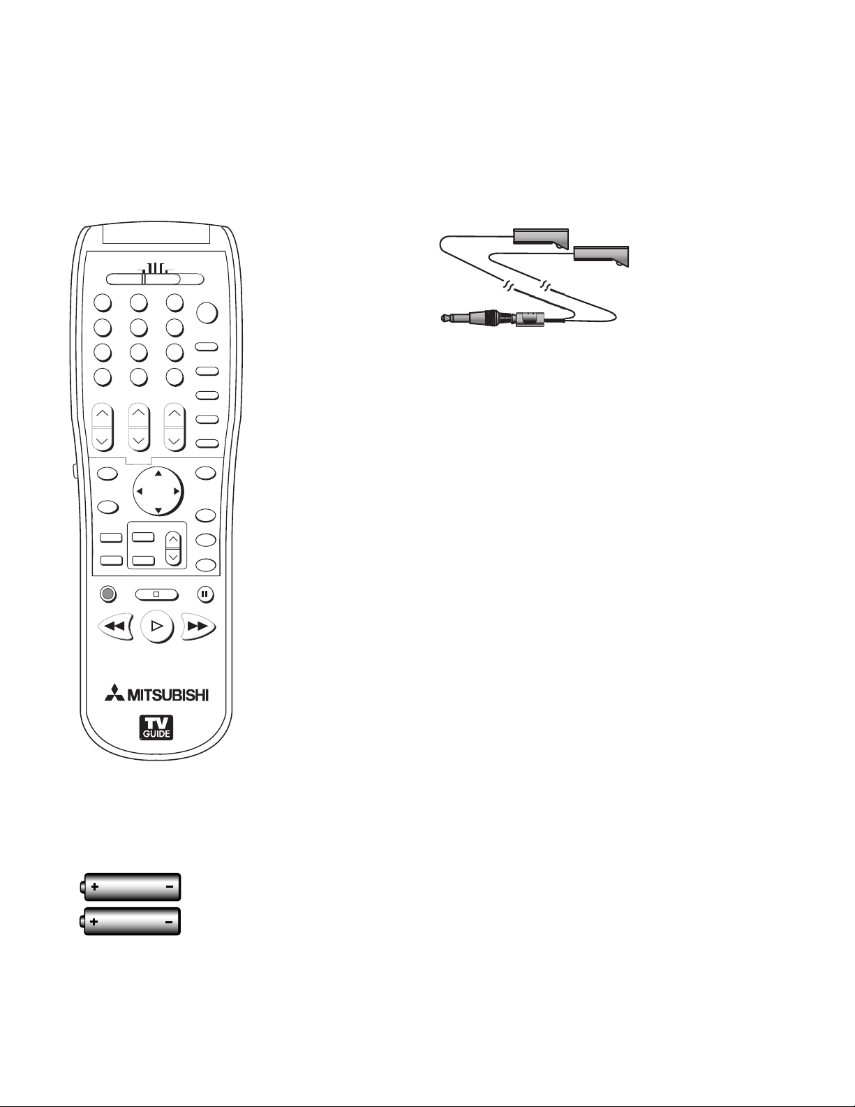
3 One Double IR Emitter Cable (allows NetCommand
to control other devices)
4. Product Registration Card (not pictured)
5. Owner’s Guide (not pictured)
1. Remote Control
2. Two AAA Batteries
6. Quick Reference Card (not pictured)
7. TV Guide On Screen® Interactive Program Guide
User’s Manual (not pictured)
10 Chapter 1. Television Overview
Page 11

Special Features
Your new High Definition widescreen television has many special features that make it the perfect center of
your home entertainment system, including:
High Definition DLP™ Display System
Your widescreen Mitsubishi HDTV uses Texas Instruments most advanced Digital Light Processing™ technology
for rear projection televisions. This TV is truly a high-performance multimedia monitor uniquely capable of both
stunning high-definition video images and clear, detailed, high-resolution PC images. Your TV is able to accept
video signals from an antenna or direct cable in standard video scanning rates of 480i, 480p, 720p, 1080i and
1080p. It is also able to accept, through the HDMI 2 connection, signals with PC resolutions from VGA (640 x 480)
through XGA (1024 x 768). When used with a compatible graphics card and controlling software, this TV is also
able to accept the custom PC resolution of 720p (1280 x 720). When connecting a PC to HDMI you will need a PC
video card with DVI or HDMI output. Also, so the TV can apply the correct PC signal processing, you will need to
set up the TV to receive the PC signals through the HDMI 2 input by using the NetCommand setup system. All of the
compatible video and PC signals will be converted to 1080p for final display; some signals will, however, add black
side bars, top and bottom bars, or both to fill the screen, and some signals will display standard video overscan.
TV Guide On Screen® Interactive Program Guide System
An eight-day on-screen program guide that can be used with cable, over-the-air and CableCARD™ reception. The
subscription-free guide system lists regular, digital and high-defintion programming. This system allows multiple
sorting options and easy program recording. Program listings are downloaded while your TV is turned off, so that
you have current program information available every day. Note that when the system is first set up, it may take up
to 24 hours to begin to receive TV program listings. It may take one week to receive all eight days of TV program
listings.
Digital Cable Ready (CableCARD™)
Your widescreen Mitsubishi HDTV is “Plug-and-Play” ready. It can descramble a cable provider’s one-way digital
signals with the use of a CableCARD security module. The CableCARD is used in place of a traditional cable box
to access digital cable programming (including high definition). Contact your local cable provider for availability
information and service details.
NetCommand® Home Network Control System
Your widescreen Mitsubishi HDTV offers a new level of networking to combine selected older products with new
and future digital products. NetCommand supports IEEE 1394 connections, Audio Video Control system (AV/C),
5C copy protection and IR control of selected older products such as VCRs, DVD players, cable boxes or satellite
receivers. NetCommand includes the ability to learn remote control signals directly from many devices, allowing you
to customize the NetCommand system in a way that works best for your viewing
16:9 Widescreen Picture Format
Enjoy a full theatrical experience in the comfort of your home. View pictures as film directors intended them. Digital
TV broadcasts, DVDs and newer video game consoles support this widescreen format.
Media Cards
You can display a slide show of your favorite JPEG pictures or listen to MP3 or WMA audio selections that have been
recorded on compatible media cards
Chapter 1. Television Overview 11
Page 12
Front Control Panel
<
DEVICEGUIDE
CANCEL
MENU
ENTER
MENUFORMAT
– CH –
<
>
ADJUST
– VOL –
<
>
>
< >
POWER
SYSTEM
RESET
LAMP STATUS TIMER
<
ENTER
– CH –
<
>
ADJUST
– VOL –
<
>
>
< >
POWER
SYSTEM
RESET
LAMP STATUS TIMER
<
DEVICEGUIDE
CANCEL
MENU
ENTER
MENUFORMAT
– CH –
<
>
ADJUST
– VOL –
<
>
>
< >
POWER
SYSTEM
RESET
LAMP STATUS TIMER
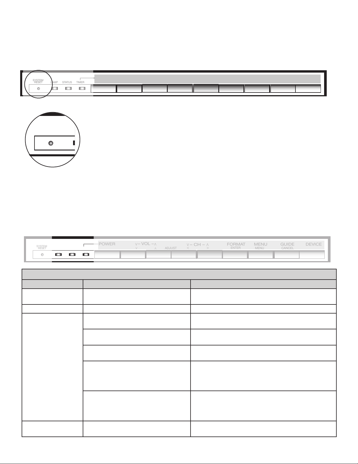
The shaded buttons on the front control panel are duplicated on the remote control. The top row of labels shows the
control functions when there are no TV menus displayed on the screen. The bottom row of labels shows the control
functions when the TV menus are displayed on the screen or when a special function has been activated. See
“Remote Control Overview” for further details on the functions of these buttons.
System Reset
If the TV does not respond to either the remote control or the front panel controls and/or
does not power Off, press the SYSTEM RESET button with a pointed item like the end
point of a paperclip. The TV will turn Off and the TIMER light will flash quickly for about
one minute. When the TIMER light stops flashing, you may again turn on the TV. The
changes you made the last time the TV was on before you used the SYSTEM RESET
button may be lost; any changes that were previously saved are not lost, however.
A/V Reset
There may be times when you wish to reset the A/V (Audio and Video) settings back to the factory defaults. To
return all of the settings at once, press GUIDE and FORMAT on the front panel at the same time. To reset the
defaults for individual devices, use the A/V Memory Reset selection on the Audio/Video menu.
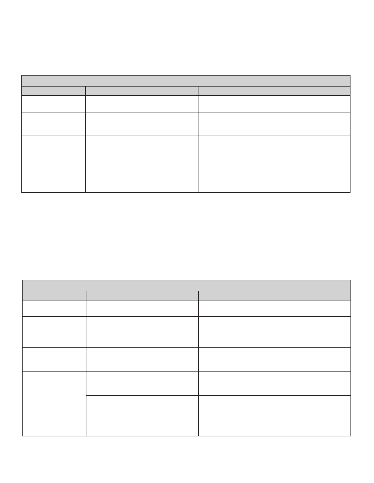
Front-Panel Indicator Lights
Power/Timer Indicator
Indicator Color TV Condition Additional Information
None (indicator
TV is powered OFF. Normal operation.
off)
Green, steady TV is powered ON. Normal operation.
Green, rapid
blinking
1. TV just plugged into AC outlet. Wait until blinking stops before turning on
(approximately 1 minute). Normal operation.
2. AC just restored after power failure. Wait until blinking stops before turning on
(approximately 1 minute). Normal operation.
3. TV Rebooting after System Reset
used.
4. TV Rebooting after power
fluctuation or receiving abnormal
Wait until blinking stops before turning on
(approximately 1-2 minutes). Normal operation.
Wait until blinking stops before turning on
(approximately 1 minute). Normal operation.
digital signals from digital channel,
CableCARD™, or digital device.
5. You have begun the procedure to
update software from an authorized
flash memory device.
For detailed information, see the instructions
that accompany the authorized software update.
Important: Do not use non-authorized software at
any time.
Green, slow
blinking
TV powered off and automatic-on
timer is set.
Normal operation. TV can be turned on at any
time.
12 Chapter 1. Television Overview
Page 13
Front Control Panel, continued
Status Indicator
Indicator Color TV Condition Additional Information
None (indicator
off)
Yellow, steady Room temperature is too high. TV will not operate when the ambient room
Red, either steady
or blinking
Normal TV on or standby condition. Normal operation.
temperature is too high. Turn off the TV and wait
until the room temperature drops.
TV may require service. Turn off the TV and unplug the set from the AC power
source. Wait one minute and then plug the set back
in.
If the LED is still on, contact your dealer or a
Mitsubishi Authorized Service Center. See www.
mitsubishi-tv.com or call 1-800-332-2119 to receive
Authorized Service Center information.
Lamp Indicator
Indicator Color TV Condition Additional Information
None (indicator
off)
Green, rapid
blinking
Yellow, steady Lamp nearing end of useful life. This is a recommendation to have a new lamp
Yellow, blinking 1. Lamp access door is open or not
Red, steady Lamp no longer illuminates and has
Normal TV on or standby condition. Normal operation.
TV just powered off and lamp is
cooling.
secure.
2. No lamp installed. TV will not operate without a lamp. See Appendix
reached the end of the lamp life.
Begins to blink 30 seconds after turning off TV.
TV can be turned on before it begins to blink or
after the blinking stops, but not while the indicator
is blinking. Normal operation.
ready before the current lamp stops illuminating.
See Appendix H for ordering information.
TV will not operate until lamp access door
is secure. See Appendix H for installation
information.
H for installation information.
Replace the lamp. The TV will not operate when
the lamp no longer illuminates. See Appendix H
for installation information.
Chapter 1. Television Overview 13
Page 14

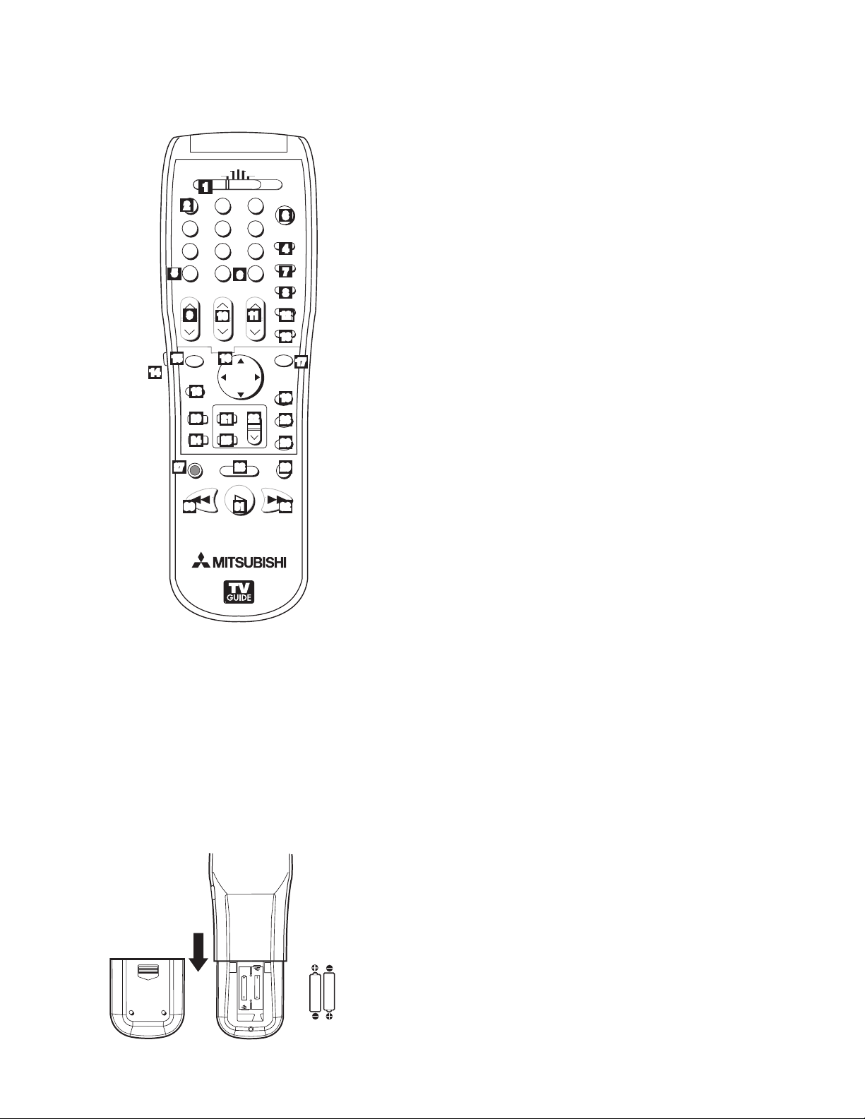
Remote Control
Overview
Figure 1, following page
1. Slide Switch: Selects A/V product to be controlled
by the remote control. Select TV for NetCommand®
device control.
2. Numbers: Individually select channels or enter
information into menus.
3. POWER: Turns power on and off for TV and other
A/V products.
4. GUIDE: Displays or removes TV Guide On Screen or
ChannelView for ANT-1 and 2. Displays Track List for
A/V Disc. Displays program guide for satellite receiver,
or DVD Disc menu. Displays thumbnails or play lists
for media card files.
5. SQV (SuperQuickView™): Scans through
memorized lists of favorite channels.
6. QV (QuickView™): Switches between the current
channel and last channel viewed.
7. SLEEP: Sets the TV to turn off within 2 hours. See
next page for setup instructions.
8. VIDEO: Selects and adjusts individual video settings.
9. DEVICE: Displays the Device Selection menu to
select the device to view (ANT-1 and ANT-2, or
devices connected to the TV’s inputs, including IEEE
1394 devices).
10. CH(ANNEL)/PAGE: Scans up or down through
memorized channels. When used with TV Guide
On Screen® and ChannelView, pages up and down
through screens.
11. VOLUME: Changes sound level.
12. AUDIO: Selects and adjusts individual audio settings.
13. MUTE: Turns sound on or off.
14. Light: Located on the left side of the remote control,
this feature illuminates buttons or labels.
15. ENTER/EXCH: Selects a channel number or menu
item. Exchange PIP and main TV picture. If PIP is
displayed, it must be cancelled before using the onscreen menus for devices.
16. ADJUST: Press to navigate TV Guide On
Screen, menus, change settings, and move the PIP
on-screen location. Operates many NetCommand
functions.
18. TV MENU: Displays on-screen menu system.
19. DEVICE MENU: Displays or removes the options menu
for TV Guide On Screen. Displays the menu for devices
connected to the TV, including CableCARD™. For VCR
or DVDs, the first press displays the transport menu, the
second press displays the VCR or DVD menu.
20. V-CHIP: Turns On or Off the V-Chip Lock.
21. PIP: Turns on PIP and cycles through PIP display
choices.
22. PIP CH: Scrolls up or down through memorized
channels for PIP
23. HOME: Exits TV on-screen menus and the TV Guide
On Screen system and returns to TV viewing.
24. FORMAT: Changes the shape and size of the main TV
picture.
25. PIP DEVICE: Displays PIP Selection menu to select
the PIP image source device
26. INFO: First press displays an on-screen summary
of the current device used and any broadcast
information available (including current V-Chip
information). See Appendix D for details. While in the
TV Guide On Screen system, press the info button to
cycle through the available info box sizes.
27. REC (Record)/CONNECT: Displays the Record
menu for setting up recordings. Records with a VCR,
sets up recordings for DVCR, IEEE 1394 devices, or
while in ChannelView. When Listings screen for TV
Guide On Screen is displayed, will start a recording.
CONNECT: Initiates IEEE 1394 peer-to-peer
connections.
28. STOP: Stops a VCR, DVD, A/V Disc or media card file.
29. PAUSE: Pauses a live TV picture when no PIP image is
displayed. When PIP image is visible, pauses that image.
Pauses a VCR, DVD or A/V Disc, media card file.
30. REW/REV: Rewinds a VCR. Reverses scan with a DVD,
A/V Disc or media card file.
31. PLAY: Plays a VCR, DVD, A/V Disc or media card file.
32. FF/FWD: Fast forward a VCR or media card file, or fast
play a DVD.
17. SUB/CANCEL: Clears SQV and some menu entries
and cancels recordings. For digital channels, adds
separator between major and sub channel numbers.
14 Chapter 1. Television Overview
Page 15
Remote Control, continued
108&3
)0.&
1"64&
3&$
'''8%3&83&7 1-":
4501
27
70-6.&
*/'0
&9$)
&/5&3
57.&/6
%&7*$&
.&/6
7$)*1
'03."5
1*1$)
427
%&7*$&
4-&&1
7*%&0
"6%*0
.65&
$)"//&-
"%+645
1*1
1*1%&7*$&
$"/$&-
57
"6%*0
$"#-&%#4%57 %7%
7$3
(6*%&
46#
$0//&$5
1"(&
"""BMLBMJOF
CBUUFSJFT
" " "
" " "
1
2
5
9
10
15 16
14
18
20
21
25
24
27 29
6
28
3130
3
4
7
8
12
11
12
13
17
19
22
23
26
32
Care
For Best Results from the Remote Control:
• Be within 20 feet of the equipment.
• Do not press two or more buttons at the same time
unless instructed.
• Do not allow unit to get wet or become heated.
• Avoid dropping on hard surfaces.
• Do not use harsh chemicals to clean. Use only a soft,
lightly moistened cloth.
• Do not mix new and old batteries.
• Do not heat, take apart or throw batteries into fire.
• Use only AAA alkaline batteries.
Hint: If the remote is in the TV layer and does
not function, press POWER and 935 to reset the
remote.
Battery Installation
Figure 2
Installing the Batteries:
1. Remove the remote control’s back cover by gently
pressing the ribbed tab in the direction of the arrow
and sliding off the cover.
2. Load the batteries, making sure the polarities (+) and
(-) are correct. For best results, insert the negative (-)
side first.
Figure 1. Remote Control Overview
Sleep Timer
Setting the Sleep Timer:
1. Press SLEEP on the remote control.
2. Each additional press of SLEEP increases the time
displayed by 30 minutes, until the maximum value of
120 minutes is reached.
3. After 5 seconds of inactivity, the message will
disappear.
4. Press SLEEP to view the remaining time before the
timer turns the TV off.
Cancelling the Sleep Timer:
1. Press SLEEP to display the on-screen message.
2. Press SLEEP repeatedly until OFF is displayed.
Note: After 5 seconds of inactivity, the message
box disappears.
Figure 2. Operation: Installing the Batteries
Chapter 1. Television Overview 15
Page 16
COMPONENT
YPbPr (480i/480p/720p/1080i)
INPUT
1
2
S-VIDEO
VIDEO
AUDIO-
LEFT/
(MONO)
AUDIORIGHT
DTV/CABLE/
VHF/UHF
ANT 1 / MAIN
ANT 2 / AUX
DIGITAL
AUDIO
OUTPUT
CableCARD™
USE WITH ANT 1 CARD TOP
1
2
Y
Pb
Pr
AUDIO-
LEFT/
(MONO)
AUDIO-
RIGHT
OUTPUT
AUDIO
OUTPUT
RECORD
OUTPUT
DVI
Analog Audio
1
2
VIDEO
AUDIO-
LEFT/
(MONO)
AUDIORIGHT
MONITORLINK™/HDMI
VIDEO 480i/480p/720p/1080i
AUDIO PCM LINEAR
1
2
IEEE 1394
INPUT/
OUTPUT
Net Command
IR EMITTER
¸
',INK
¸
INPUT
PC - 60Hz
VGA, W-VGA,
SVGA, W-SVGA,
XGA, 1280 X 720
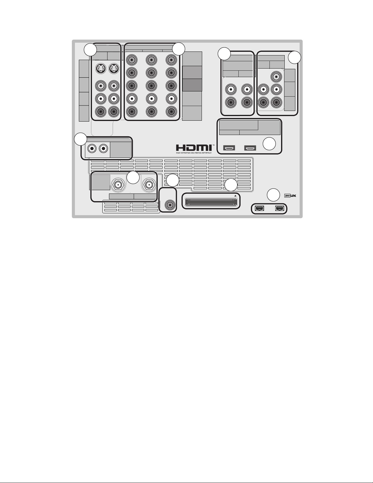
TV Back Panel
10
4
5
6
7
9
3
2
1
8
1. Antenna (ANT-1 MAIN, ANT-2 AUX)
ANT-1 MAIN and ANT-2 AUX can each receive both digital
and analog over-the-air channels from a VHF/UHF antenna
or non-scrambled digital/analog cable source.
Your primary viewing signal source should be connected
to ANT-1 MAIN. ANT-1 MAIN must be used to view
premium subscription cable TV service authorized by the
CableCARD™ access card. The CableCARD access card
is provided by your local cable company. ANT-2 AUX can
receive over-the-air or non-scrambled cable signals.
2. IR EMITTER NetCommand
IR Emitters connected to these jacks are used by the
NetCommand system of the TV to control external analog
devices such as cable boxes, VCRs, DVDs, satellite
receivers and audio receivers. This system is also
coordinated with the TV Guide On Screen® system for
the control of cable boxes and to activate the record
feature of your VCR. Either connection can be used for
®
NetCommand functions.
3. INPUT 1 and 2
(Audio/Video 1 and 2)
Inputs 1 and 2 can be used for the connection of a
VCR, Super VHS (S-VHS) VCR, DVD player, standard
satellite receiver or other A/V device to the TV. Please
note that if S-VIDEO and VIDEO are available for the
input, you must choose to connect only one. They
cannot both be connected at the same time.
16 Chapter 1. Television Overview
4. COMPONENT 1, 2, and 3 Inputs
YPbPr (480i/480p/720p/1080i)
These inputs can be used for the connection of devices
with component video outputs, such as a DVD player,
external HDTV receiver, or compatible video game
system. Please see Appendix B for signal compatibility.
5. DVI Analog Audio
Unlike HDMI, DVI does not carry audio information on
the same cable. Use these analog stereo audio inputs
when using the HDMI input with a device that outputs
DVI instead of HDMI, such as DVI output from a personal
computer.
6. AUDIO OUTPUT, RECORD OUTPUT
AUDIO OUTPUT sends analog audio of the program
currently shown on the screen to an A/V surround sound
receiver or stereo system. Digital audio from digital
channels, FireWire® (DTV Link/IEEE 1394) devices and
HDMI devices is converted to analog audio by the TV. If
you do not have a digital A/V receiver, this should be the
only audio connection between the TV and your analog
A/V receiver or stereo system.
RECORD OUTPUT sends analog audio and video to a
VCR for recording purposes. These signals may not be
the same as those of the program that is currently being
shown on screen. Signals from digital channels and
FireWire (IEEE 1394) devices are converted to analog
signals. There is no video signal when copy restrictions
Page 17

TV Back Panel, continued
are in effect. Audio alone is output when Component 1, 2,
or 3, or the HDMI input is selected for recording.
7. HDMI™ 1 and 2
The HDMI (High Definition Multimedia Interface)
supports uncompressed standard and high-definition
digital video formats and PCM digital audio format.
Use these inputs to connect to EIA/CEA-861 compliant
devices such as a high-definition receiver or DVD player.
These inputs support 480i, 480p, 720p and 1080i video
formats.
These inputs can also be used as a DVI connection with
separate analog audio inputs. An optional HDMI-to-DVI
adaptor or cable is necessary to make this connection
and may be available from your local electronics retailer.
When using the optional HDMI-to-DVI adapter, the DVI
analog audio inputs on your TV allow you to receive left
and right audio from your DVI device.
This input is HDCP (High-Bandwidth Digital Copy
Protection) compliant.
access card customized to your account. This card
allows the TV to receive, decode and unscramble the
premium digital channels included in your cable TV
subscription without the use of a cable box. See page
23 for additional CableCARD information and activation
instructions.
If your cable company is not currently offering
CableCARD access cards, you will need to use a
cable box provided and authorized by your local cable
company to view scrambled channels.
10. Digital Audio Output
This output sends Dolby® Digital or PCM digital audio to
your digital A/V surround sound receiver. Analog audio
from analog channels and devices is converted by the
TV to PCM digital audio. In most cases, this should be
the only audio connection between the TV and your A/V
receiver. If you have MP3 audio sources, however, you
need to connect the TV’s analog AUDIO OUTPUT (left
and right) to your A/V receiver.
HDMI 2
HDMI 2 also allows the TV to display DVI or HDMI output
from a PC. To view PC video on the TV, you must activate
the PC option in NetCommand. You can do this during
initial NetCommand setup (in the Device Setup screen),
or at any time afterwards by using the NetCommand Add
function.
If you want audio from a PC when using PC DVI output,
you must connect the PC audio output to the TV INPUT/
DVI Analog Audio 2, located above the HDMI 2 input.
8. DTV Link™/IEEE 1394
These jacks allow the TV to connect to external IEEE 1394
digital products by means of a single cable. Two jacks
are provided for this purpose, which allow for a high
degree of flexibility for connecting your NetCommand
controlled system. Detailed information regarding IEEE
1394 connection requirements are in Chapter 4.
9. CableCARD™ Slot
The CableCARD access card from your cable TV service
provider is inserted into this slot. The top of the card
should face in the direction indicated by CARD TOP .
CableCARD is a nationwide standard system that allows
your local cable TV provider to supply you with an
Chapter 1. Television Overview 17
Page 18
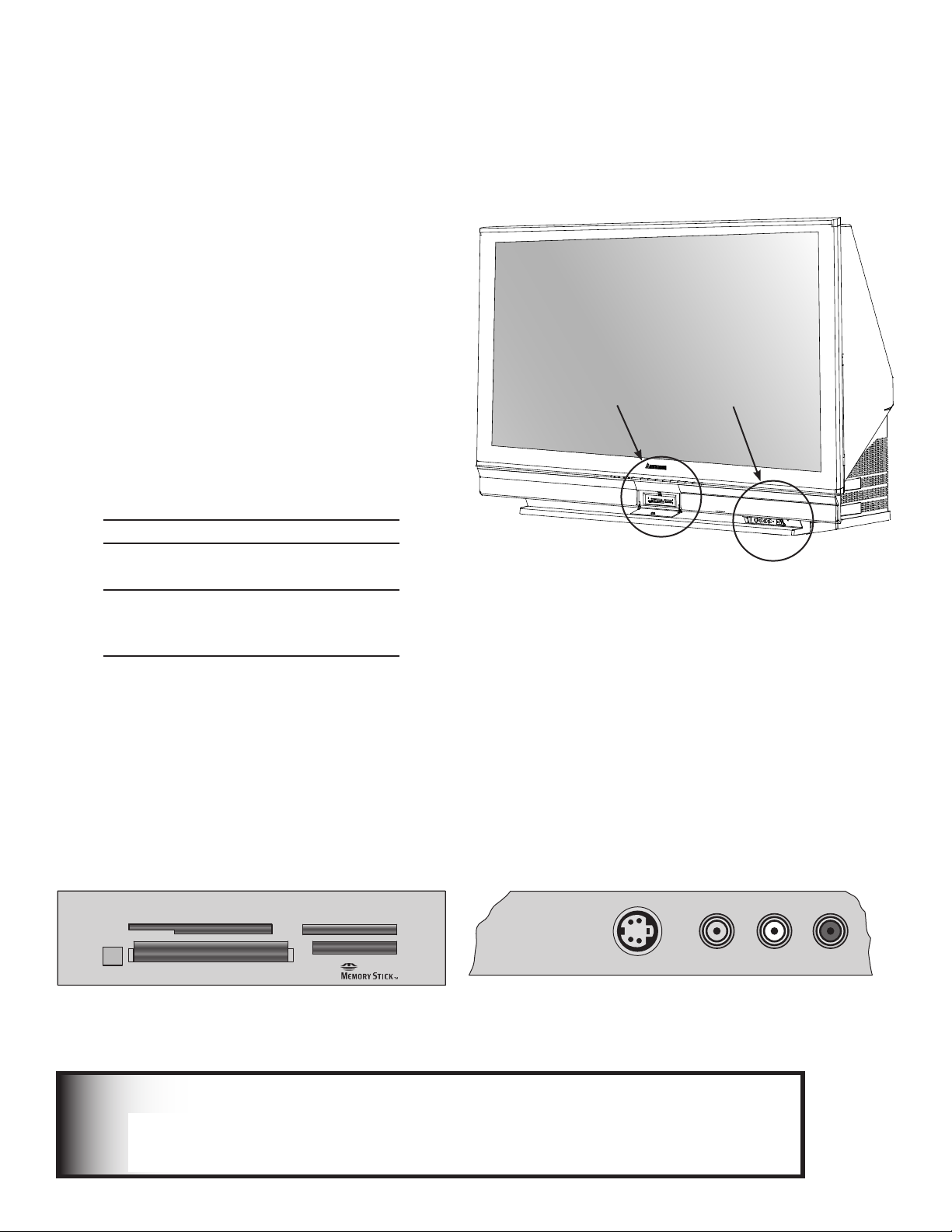
Media Card Slots and Front-Panel Inputs
$"3%4NBSU.FEJB
5.
$"3% $PNQBDU'MBTI
¥
.JDSP%SJWF
¥
$"3%130
5.
%*%#4
$"3% .VMUJNFEJB$BSE
5.
4%$BSE
36)$%/
).054
6)$%/ ,!5$)/2
Media Card Slots
To access the media card slots, press on the center
panel labelled PUSH. There are four card slots in the
front of the TV that allow the display of JPEG pictures
from many digital cameras, MP3 or WMA audio files
recorded from computers or other digital recording
devices.
The card slots are designed for the specific types of
cards listed below. Other cards or objects should
not be inserted into the slots as this may damage the
TV. See media card (slide show, play list) Setup for
details about JPEG, MP3 and WMA file types that are
compatible with the TV.
Card Compatibility
Slot Card Types
CARD 1 SmartMedia™
CARD 2
CARD 3
CARD 4
MultiMediaCard™
Secure Digital (SD)
CompactFlash®,
Types I and II
Microdrive®
Memory Stick PRO™
Memory Stick™
Front-Panel Input 3
These jacks allow for convenient connection of audio/
video devices to the front of the TV. Use the Input 3
jacks to connect a camcorder or other audio/video
device. Please note that if you connect to the S-VIDEO
terminal, the VIDEO terminal is deactivated. The
VIDEO terminal is active only when there is no S-Video
connection.
Memory
Card Reader Input 3
Card slots
Portions of the advanced circuitry of this TV must continue to operate even when the
TV is turned off. Some of these circuits therefore need to be cooled at all times. A lowpower standby fan may be heard in a quiet environment. This is normal operation.
18 Chapter 1. Television Overview
Input 3 on front panel
IMPORTANT
Page 19

Additional Information
Using the System Reset Button
If the TV doesn’t respond to either the remote control
or the front panel controls or will not power off, press
the SYSTEM RESET button on the front panel with a
pointed item such as the point of a ball point pen or
end tip of a paperclip.
The TV will turn off and the green LED will flash
quickly for about one minute. When the green LED
stops flashing, you may turn on the TV again. The
changes you made while the TV was most recently
on, before you used the SYSTEM RESET button may
be lost; the changes you made previously, however,
are not lost. Only those changes since the last power
On may be lost when the system reset button is
pressed. All other settings are retained.
Using the Reset Menu to Reset the TV
Read on-screen warnings before
proceeding, as some user data or
settings may be erased.
1. Select any device from the Device Selection
menu. Press TV MENU followed by 1,2,3 to see
the RESET SERVICE MENU to reset the TV.
2. Select Reset System Defaults (CAUTION: All
settings, except V-Chip, will be reset to the
original factory defaults).
Demo Mode
This TV has a demo mode for use in retail stores. To turn the demo mode On/Off, press the following buttons in
sequence:
MENU, 0, QV, 0
IMPORTANT
Do not attempt to update the software of this TV with software or cards that are not provided
by or authorized by Mitsubishi Digital Electronics America, Inc. Non-authorized software may
damage the TV and will not be covered by the warranty.
Chapter 1. Television Overview 19
Page 20

Page 21

Chapter . . .
Connecting
External Devices and NetCommand® Setup . . . . . . . . . . . . . . . . 22
CableCARD™ Technology . . . . . . . . . . . . . . . . . . . . . . . . . . . . . 23
Wall Outlet Cable . . . . . . . . . . . . . . . . . . . . . . . . . . . . . . . . . . . 24
Standard Cable Box . . . . . . . . . . . . . . . . . . . . . . . . . . . . . . . . . 24
Antenna with a Single Lead . . . . . . . . . . . . . . . . . . . . . . . . . . . . 25
2
Antennas with Separate UHF and VHF Leads . . . . . . . . . . . . . . . . 25
VCR to an Antenna or Wall Outlet Cable (Audio & Video) . . . . . . . . 26
VCR to a Cable Box (Audio & Video) . . . . . . . . . . . . . . . . . . . . . . 27
A/V Receiver (Stereo System) . . . . . . . . . . . . . . . . . . . . . . . . . . 28
Satellite Receiver or Other Device with S-Video . . . . . . . . . . . . . . 28
DVD Player with Component Video . . . . . . . . . . . . . . . . . . . . . . . 29
DVI Device . . . . . . . . . . . . . . . . . . . . . . . . . . . . . . . . . . . . . . . . 29
HDTV Cable Box or Satellite Receiver with Component Video . . . . 30
HDMI Device . . . . . . . . . . . . . . . . . . . . . . . . . . . . . . . . . . . . . . 30
Computer with an HDMI Monitor Output . . . . . . . . . . . . . . . . . . . 31
Computer with a DVI Monitor Output . . . . . . . . . . . . . . . . . . . . . 31
IR Emitter NetCommand® . . . . . . . . . . . . . . . . . . . . . . . . . . . . . 32
Compatible IEEE 1394 Devices . . . . . . . . . . . . . . . . . . . . . . . . . . 33
Helpful Hints . . . . . . . . . . . . . . . . . . . . . . . . . . . . . . . . . . . . . . 35
Page 22
Connecting External Devices and NetCommand® Setup
Model
M-VR800 &
M-VR1000
Model
M-VR900 &
M-VR700
Model
Lifestyle®28
Model
AVR-2700
Model
DTR-9.1
Model
VR-2080
Model
SR8200
Model
VSX-D557
Model
VSX-49TX
Model
RSX-1065
Model
STR-DE825
Model
RV-X2095
Model
RX-V2200
Device Audio Output to AV Receiver Inputs by Name
VCR
VCR 1 VCR VCR VCR-1 Video 1 Video 1 VCR1
VCR/Tape
VCR 1/DVR Video 2 Video 1 VCR 1 VCR 1
Satellite Receiver Aux
Cable/DBS AUX CD Video 3 Video 3 DSS CD SAT Video 4 TV/DBS TV/DBS D-TV/LD
DVD Player
DVD DVD (built-in) DVDVDP DVD Video 4 DVD LD/SAT DVD/LD Video 5 TAPE/MD CD DVD
TV Monitor Output
(& Digital Audio)
TV TV TV TV/DBS Video 4 Video 4 TV DVD/TV TV Video 1 DVD/LD DVD/LD CBL/SAT
Chart 2
Mitsubishi 1 Mitsubishi 2 Bose Denon Integra Kenwood Marantz Pioneer 1 Pioneer 2 Rotel Sony Yamaha 1 Yamaha 2
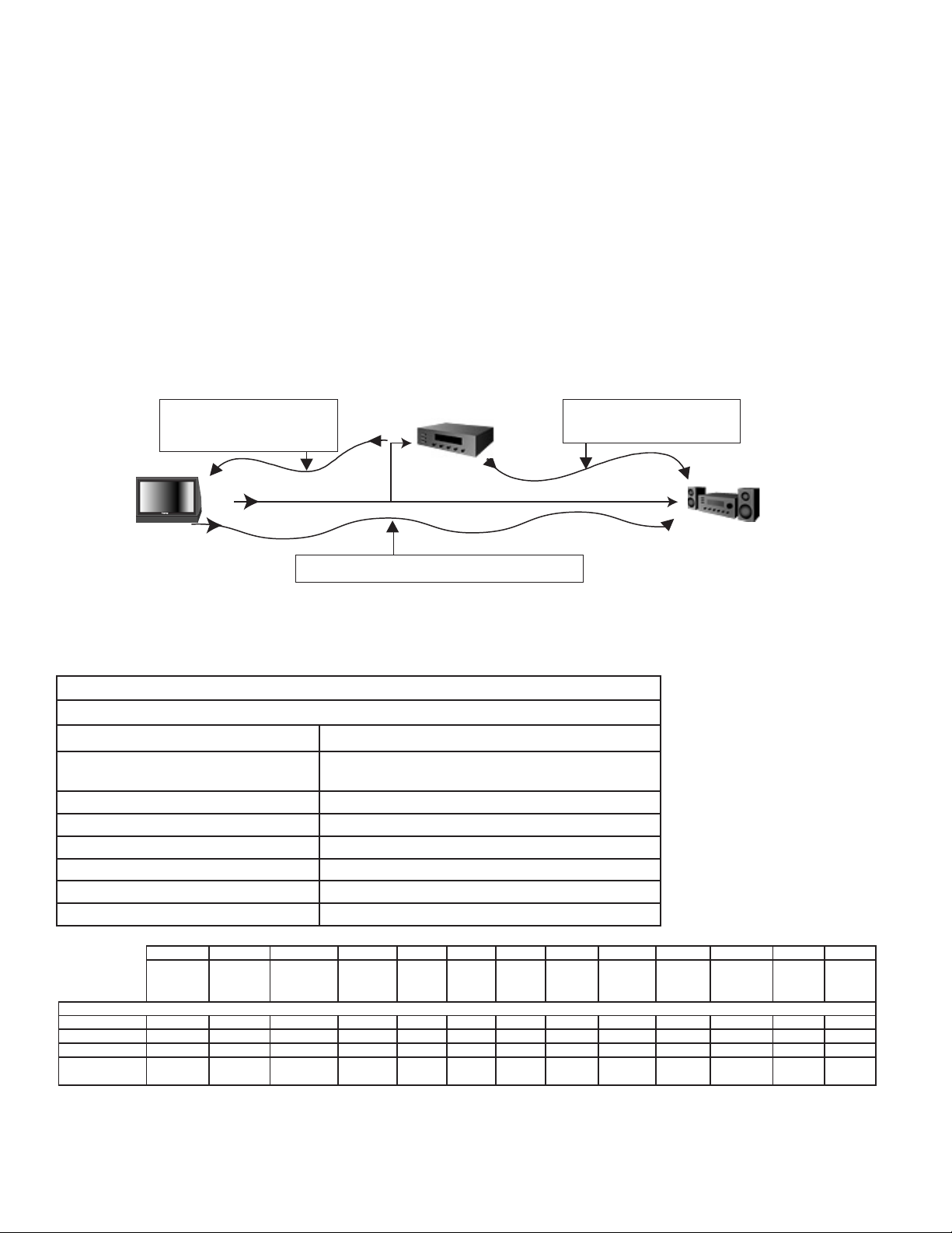
AV
Receiver
TV
Device to be
connected
stereo and/or digital
audio cables
video and stereo
audio cables
stereo and/or digital audio cables
*3&NJUUFST
NetCommand is able to control many current audio and video devices by sending remote control signals from the TV
to each device through IR emitters. Additionally, it is also able to learn the remote control signals used by most audio
video devices not already in the TV’s memory. NetCommand can automatically switch the TV and compatible or
learned Audio/Video (A/V) Receivers to the correct input used with each device. It is important that the inputs on the
TV and A/V receiver back panels match the NetCommand setup that is displayed on screen.
To simplify the installation of NetCommand, there is a step-by-step on-screen NetCommand Setup procedure in this
chapter, which details the type and brands of devices you are connecting to the TV. The NetCommand Setup also
assigns preset TV and A/V receiver inputs for each device. You should connect each device to the TV input (both audio
and video) and to the A/V receiver (audio) as shown in the figure below. If you connect devices to inputs other than the
ones shown as presets, you must change the NetCommand setup accordingly. See the Edit NetCommand information
starting on page 47.
The following charts show which preset inputs you should use on the TV and A/V receiver.
Chart 1 shows the default TV inputs existing in NetCommand.
Chart 2 shows the A/V receiver inputs used by A/V receiver models already known by NetCommand.
Chart 1
NetCommand Default Device Audio and Video Outputs to TV Inputs
Cable for CableCARD™ Service ANT-1
Antenna/Cable (digital/analog) ANT-1 if primary viewing source,
Cable box COMPONENT-1
VCR Input-1
Satellite Receiver (SAT) Input-2
Camcorder Input-3 (on front panel)
DVD Player COMPONENT-2
PC HDMI-2
After using NetCommand Setup, you may go to the NetCommand menu at any time to change the inputs you used
for connecting each device, custom name devices, add devices not included in the presets above or delete devices
no longer used. See Edit NetCommand. See Helpful Hints at the end of this chapter for additional information on
device setup.
22 Chapter 2. Connecting
ANT-2 if secondary viewing source
Page 23

Please call XYZ Cable
at xxx-xxx-xxxx to
activate cable service.
They will need these numbers:
Host ID X-XXX-XXX-XXX-XXX
CableCARDTMID: X-XXX-XXX-XXX-XXX
See owner's manual for
further information
CableCARD™ Technology
CableCARD Technology
CableCARD is a nationwide system standard that
allows your local cable TV provider to supply you with
an access card customized to your account. This card
allows your TV to receive, decode and unscramble the
premium digital channels included in your cable TV
subscription without the use of a cable box. It also
allows your cable provider to automatically update
and change your subscription. When you move to
a new cable provider’s area, you simply return the
CableCARD to the original cable provider and get a
new card from your new cable provider.
Please note that CableCARD is a new technology and
your local cable provider may not currently be offering
this service. As time passes, this system will become
broadly supported by most cable providers.
The CableCARD system is “unidirectional” which
means your cable provider can send updates to the
access card and TV, however, the TV cannot send
back signals such as requests for Video-On-Demand
or Pay-per-View programs by remote control.
Digital cable channels authorized by the CableCARD
will be available on the Firewire® IEEE 1394 network
and can be shared by other products on the network.
Some digital channels or programs may not be copied
or recorded because of copy restriction limits set by
the content owners or copyright holders.
The digital television is capable of receiving analog
basic, digital basic and digital premium cable
television programming by direct connection to
a cable system providing such programming. A
security card (CableCARD) provided by your cable
operator is required to view encrypted digital
programming. Certain advanced and interactive
digital cable services such as video-on-demand, a
cable operator’s enhanced program guide and dataenhanced television services may require the use of a
set-top box. For more information call your local cable
operator.
Using a CableCARD
After inserting a CableCARD into the TV back
panel CableCARD slot and powering On the TV, the
initialization process begins. An initial screen will
automatically display for a few minutes, with information
that your Cable Provider will need in order to start
service. Please write down this information before calling
your cable provider.
An example of an initial screen is shown here. Your
screen will display specific information from your cable
provider and may not look like this screen.
If you were unable to record the information, you can
press TV MENU on the remote and then enter the
number 999 and the screen will re-display. You can
also press DEVICE MENU when the CableCARD is the
selected source and you will be able to select the startup
application.
IMPORTANT
To use a CableCARD, the primary incoming
cable must be connected to ANT-1 MAIN.
Please see page 58 for instructions on how to insert
the CableCARD.
Chapter 2. Connecting 23
Page 24
Connecting a Wall Outlet Cable or Cable Box
0QUJPOBM4FDPOEBSZ
"OUFOOBPS$BCMF
1SJNBSZ8BMM
0VUMFU$BCMF
$BCMF$"3%
5.
4-05
DPWFSSFNPWFE
DTV/CABLE/
VHF/UHF
ANT 1 / MAIN
ANT 2 / AUX
DIGITAL
AUDIO
OUTPUT
CableCARD™
USE WITH ANT 1 CARD TOP
5P"/5."*/
5P"/5"69
57CBDLQBOFM
TFDUJPO
DTV/CABLE/
VHF/UHF
ANT 1 / MAIN
ANT 2 / AUX
DIGITAL
AUDIO
OUTPUT
CableCARD™ USE WITH ANT 1 CARD TOP
*/ 065
*/
065
065
5808":41-*55&3
57CBDL
QBOFM
TFDUJPO
*ODPNJOH
$BCMF
$BCMF#PYCBDL
QBOFMTFDUJPO
3'4QMJUUFS
5P"/5."*/
5P"/5"69
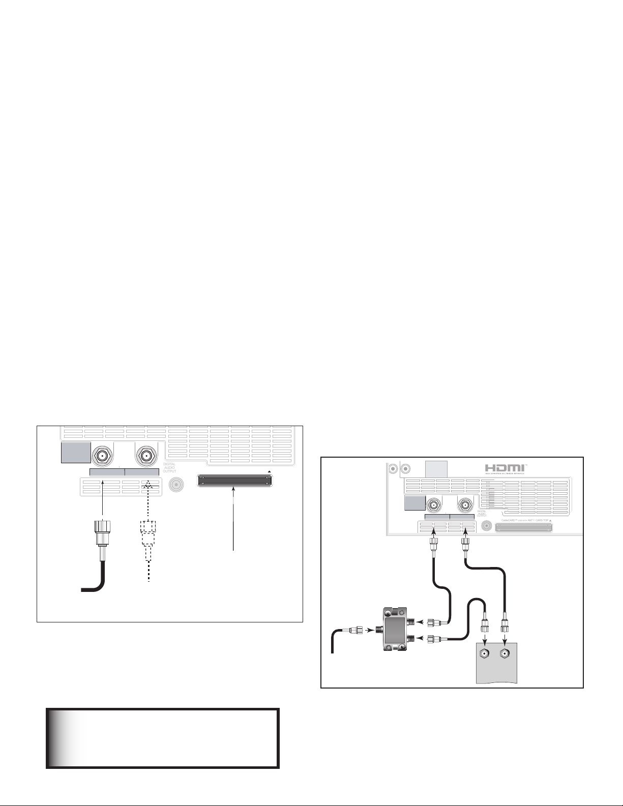
Wall Outlet Cable
(can be used with a CableCARD™)
Figure 1
It is very important to connect the incoming cable
for your primary viewing source to ANT-1, especially
for CableCARD™ use and to download TV Guide On
Screen® listings.
1. Connect the primary incoming coaxial lead cable to
ANT 1/MAIN on the TV back panel.
2. For an optional secondary antenna source, connect
an antenna (or cable) to ANT 2/AUX.
3. If you have subscribed to a CableCARD™ service,
the CableCARD can now be inserted into the
CableCARD SLOT. Using a Phillips screwdriver,
remove the CableCARD cover screws. Insert the
CableCARD, then replace the cover and screws. The
top of the card should face in the direction the CARD
TOP arrow indicates.
Additional CableCARD information is on page 20.
Detailed TV Guide On Screen information is in the
separate User’s Manual.
Standard Cable Box
(analog cable box, other than an HDTV cable box,
compatible with PIP)
Figure 2
3 coaxial cables and one two-way RF splitter are required.
These are not included with the TV.
Note: See page 29 to connect an HDTV cable box.
1. Connect the incoming cable to IN on an RF splitter.
2. Connect one coaxial cable from OUT on the RF
splitter to ANT-1 MAIN on the TV back panel.
3. Connect one coaxial cable from OUT on the RF
splitter to IN on the analog cable box.
4. Connect one coaxial cable from OUT on the cable
box to ANT-2 AUX on the TV back panel.
5. After the cable box is connected to ANT-2 AUX
as shown, open NetCommand and go to the RF
Connection for Cable screen and do the following:
a. Check the RF check box.
b. For antenna, select ANT-2.
c. For Channel, select the channel to which the TV
must be tuned for your cable box. The default
channel is 3.
When this setup is complete, you can use the TV remote
control to change channels on the cable box.
Figure 1. Wall Outlet Cable
24 Chapter 2. Connecting
IMPORTANT
Additional connection cables are
not provided with the TV. They are
available at most electronics stores.
Figure 2. Connecting a Cable Box
Note: To use a cable box connected to ANT-2 as
shown above, you must make the noted NetCommand
changes. The changes are required to change
the NetCommand cable-box default connection
(Component-1) to the actual connection (ANT-2).
Page 25
COMPONENT
YPbPr (480i/480p/720p
INPUT
1
2
S-VIDEO
VIDEO
AUDIO-
LEFT/
(MONO)
AUDIO-
RIGHT
DTV/CABLE/
VHF/UHF
ANT 1 / MAIN
ANT 2 / AUX
DIGITAL
AUDIO
OUTPUT
1
2
Net Command
IR EMITTER
¸
',INK
¸
&YUFSOBM
"OUFOOB
PS$BCMF
#BDL
7JFX
4JEF
7JFX
'MBU5XJO-FBE
6)'"OUFOOB
$IBOOFMT
7)'"OUFOOB
$IBOOFMT
0INUP
0IN
$PNCJOFS
'MBU5XJO-FBE
6)'
7)'
57CBDLQBOFMTFDUJPO
4O!.4-!).
Connecting an Antenna with a Single Lead or Antennas with
DTV/CABLE/
VHF/UHF
ANT 1 / MAIN
ANT 2 / AUX
DIGITAL
AUDIO
OUTPUT
Net Command
IR EMITTER
¸
¸
0IN
'MBU5XJO
-FBE
0QUJPOBM0IN
UP0IN
.BUDIJOH5SBOTGPSNFS
0IN
$PBYJBM
$BCMF
57CBDLQBOFMTFDUJPO
Separate UHF and VHF Leads
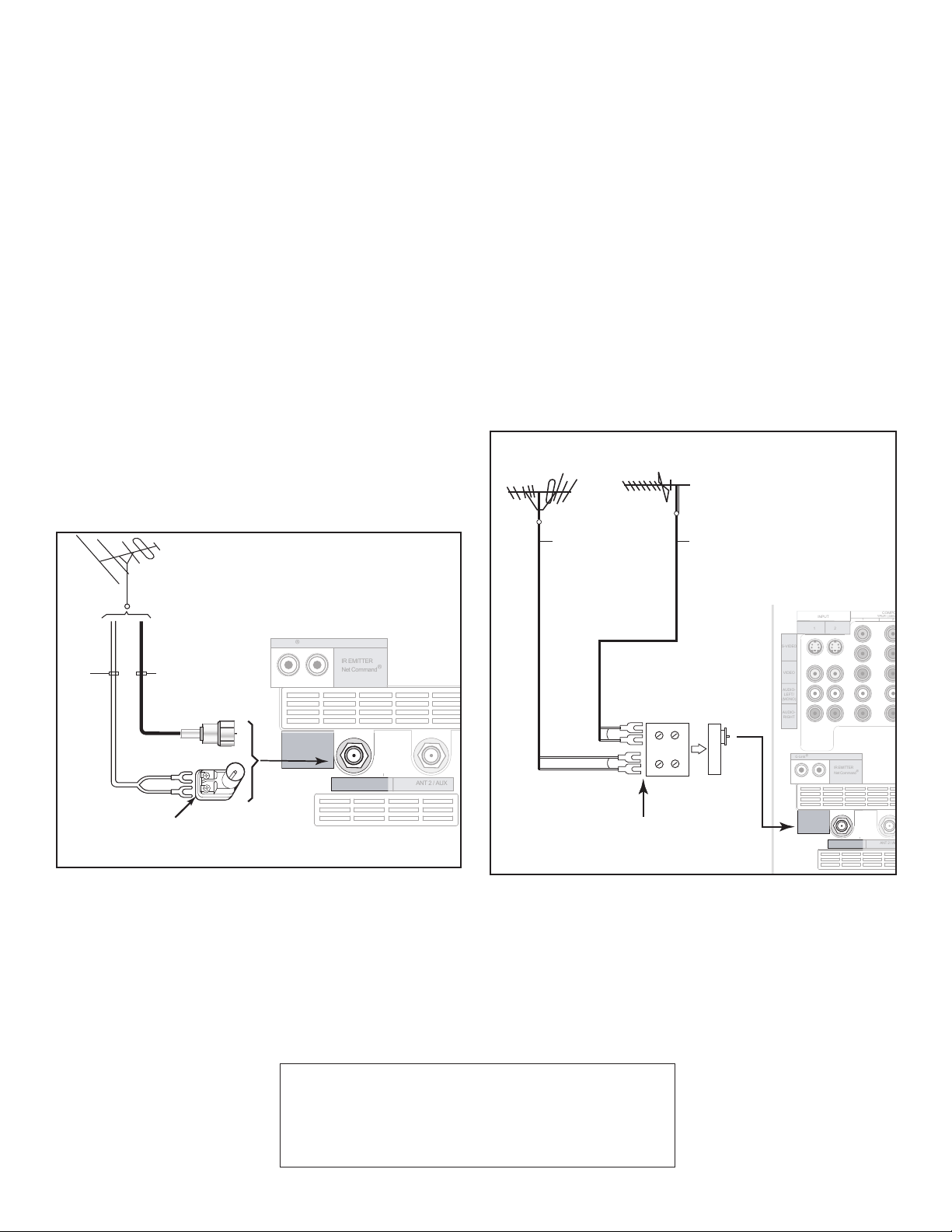
Antenna with a Single Lead
(not for use with CableCARD™)
Figure 3
For antennas with flat twin leads
A 300-Ohm to 75-Ohm transformer is required. This is not
included with the TV, but is available at most electronics stores.
1. For an antenna with flat twin leads, connect the
300-Ohm twin leads to the 300-Ohm to 75-Ohm
transformer.
2. Push the 75-Ohm side of the transformer onto ANT-1
MAIN on the TV back panel.
For cable or antenna with coaxial lead
Connect the coaxial lead directly to ANT-1 MAIN on
the TV back panel.
Antennas with Separate UHF and VHF
Leads
Figure 4
A UHF/VHF combiner is required. This is not included with the
TV.
1. Connect the UHF and VHF antenna leads to the UHF/
VHF combiner.
2. Push the combiner onto ANT-1 MAIN on the TV back
panel.
Figure 3. Connecting a Single Antenna
Chapter 2. Connecting 25
Mitsubishi strongly recommends you avoid using
antennas with flat twin leads. Flat twin lead
antenna wires are subject to interference which
may adversely affect the performance of the TV.
We recommend using coaxial antenna cable.
Figure 4. Connecting separate UHF and VHF Antennas
Page 26
Connecting a VCR to an Antenna or Wall Outlet Cable
COMPONENT
YPbPr (480i/480p/720p/1080i)
INPUT
1
2
S-VIDEO
VIDEO
AUDIOLEFT/
(MONO)
AUDIORIGHT
DTV/CABLE/
VHF/UHF
ANT 1 / MAIN
ANT 2 / AUX
DIGITAL
AUDIO
OUTPUT
CableCARD™
USE WITH ANT 1 CARD TOP
1
2
Y
Pb
Pr
AUDIO-
LEFT/
(MONO)
AUDIORIGHT
OUTPUT
AUDIO
OUTPUT
RECORD
OUTPUT
DVI
Analog Audio
1 2
VIDEO
AUDIOLEFT/
(MONO)
AUDIORIGHT
MONITORLINK™/HDMI
VIDEO 480i/480p/720p/1080i
AUDIO PCM LINEAR
1
2
IEEE 1394
INPUT/
OUTPUT
Net Command
IR EMITTER
¸
',INK
¸
INPUT
PC - 60Hz
VGA, W-VGA,
SVGA, W-SVGA,
XGA, 1280 X 720
)46
*/
065
065
5808":41-*55&3
*ODPNJOH
$BCMF
3'4QMJUUFS
7$3CBDLQBOFM
*GZPVS7$3IBTB
WJEFPDIBOOFMPS3'
0/0''TXJUDITFUJU
UP0''
"UUBDIPOMZPOFDBCMFUZQF
4WJEFPSFDPNNFOEFEJG
BWBJMBCMF
46"ACK
0ANEL
Connecting VCR Audio and Video to the TV
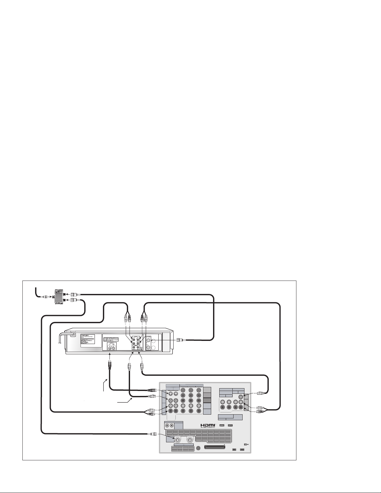
VCR to an Antenna or Wall Outlet Cable (Audio & Video)
Figure 5
A two-way RF splitter, 3 coaxial cables, right and left audio
cables and an S-Video or Video cable are required. These are
not included with the TV.
1. Connect the incoming cable or Antenna to IN on the
RF splitter.
2. Connect one coaxial cable from OUT on the RF
splitter to ANTENNA IN on the VCR back panel.
3. Connect one coaxial cable from OUT on the RF
splitter to ANT-1 MAIN on the TV back panel. This
connection also allows you to use the TV Guide On
Screen® feature.
4. To use the TV speakers with the VCR, connect a
set of audio cables from AUDIO OUT on the VCR
back panel to INPUT-1 AUDIO-LEFT (MONO) and
AUDIO-RIGHT on the TV back panel. The red cable
connects to the R (right) channel and the white
cable connects to the L (left) channel. If your VCR
is mono (non-stereo), connect only the white (left)
cable.
5. Connect either an S-Video or Video cable from
VIDEO OUT on the VCR back panel to INPUT-1
VIDEO on the TV back panel. Only one type of
video cable should be connected. S-Video is
recommended, if available.
6. For NetCommand® controlled recordings
(including TV Guide On Screen), connect a set
of audio cables from AUDIO IN on the VCR back
panel to RECORD OUTPUT/AUDIO-LEFT and
AUDIO-RIGHT on the TV back panel. The red
cable connects to the R (right) channel and the
white cable connects to the L (left) channel.
7. Complete the NetCommand controlled recordings
connections by connecting a Video cable from
VIDEO IN on the VCR back panel to RECORD
OUTPUT/VIDEO on the TV back panel.
Figure 5. Connecting a VCR to an Antenna or Wall Outlet Cable
26 Chapter 2. Connecting
Note:
NetCommand®
will assume your
VCR is connected
to inputs as shown
on this page. If
you use any other
inputs for your VCR
or add a second
VCR, this change
must match in
the NetCommand
system. See Edit
NetCommand... in
Chapter 3 for more
information.
Page 27
COMPONENT
YPbPr (480i/480p/720p/1080i)
INPUT
1
2
S-VIDEO
VIDEO
AUDIO-
LEFT/
(MONO)
AUDIORIGHT
DTV/CABLE/
VHF/UHF
ANT 1 / MAIN
ANT 2 / AUX
DIGITAL
AUDIO
OUTPUT
CableCARD™ USE WITH ANT 1 CARD TOP
1
2
Y
Pb
Pr
AUDIO-
LEFT/
(MONO)
AUDIO-
RIGHT
OUTPUT
AUDIO
OUTPUT
RECORD
OUTPUT
DVI
Analog Audio
1 2
VIDEO
AUDIOLEFT/
(MONO)
AUDIORIGHT
MONITORLINK™/HDMI
VIDEO 480i/480p/720p/1080i
AUDIO PCM LINEAR
1
2
IEEE 1394
INPUT/
OUTPUT
Net Command
IR EMITTER
¸
',INK
¸
INPUT
PC - 60Hz
VGA, W-VGA,
SVGA, W-SVGA,
XGA, 1280 X 720
)46
$BCMF#PY
CBDLQBOFMTFDUJPO
*/
065
065
5808":41-*55&3
*/
065
*ODPNJOH
$BCMF
3'4QMJUUFS
7$3CBDLQBOFM
*GZPVS7$3IBTB
WJEFPDIBOOFMPS3'
0/0''TXJUDITFUJU
UP0''
"UUBDIPOMZPOFWJEFP
DBCMFUZQFTUFQ
4WJEFPSFDPNNFOEFE
JGBWBJMBCMF
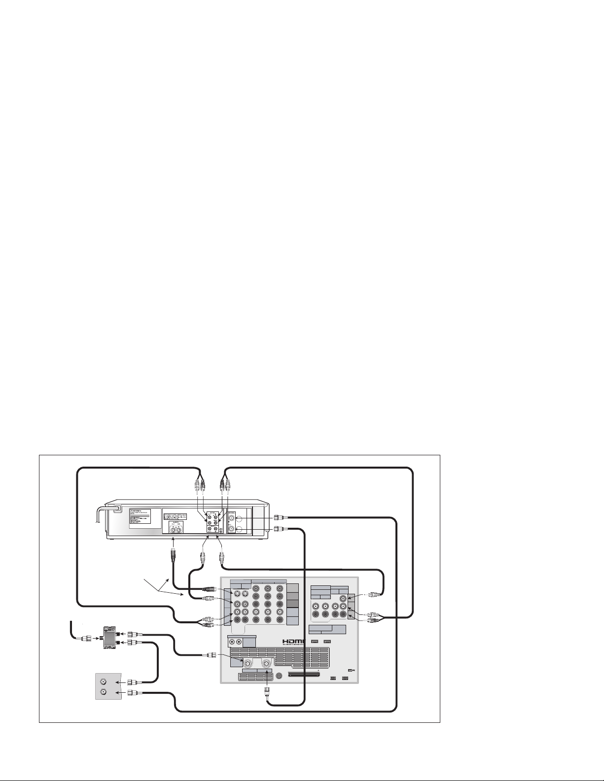
Connecting a VCR to a Cable Box (Audio & Video)
VCR to a Cable Box (Audio & Video)
Figure 6
A two-way RF splitter, 4 coaxial cables, right and left audio
cables and an S-Video or Video cable are required. These are
not included with the TV.
1. Connect the incoming cable to IN on the RF splitter.
2. Connect one coaxial cable from OUT on the RF
splitter to ANTENNA IN on the cable box back
panel.
3. Connect one coaxial cable from OUT on the RF
splitter to ANT-1 MAIN on the TV back panel. This
connection also allows you to use the TV Guide On
Screen® feature.
4. Connect one coaxial cable from OUT on the cable
box to ANTENNA IN on the VCR back panel.
5. Connect one coaxial cable from ANTENNA OUT on
the VCR back panel to ANT-2 AUX on the TV back
panel (optional).
6. To use the TV speakers with the VCR, connect a
set of audio cables from AUDIO OUT on the VCR
back panel to INPUT-1 AUDIO-LEFT (MONO) and
AUDIO-RIGHT on the TV back panel. The red cable
connects to the R (right) channel and the white
cable connects to the L (left) channel. If your VCR
is mono (non-stereo), connect only the white (left)
cable.
7. Connect either an S-Video or Video cable from
VIDEO OUT on the VCR back panel to INPUT 1
VIDEO on the TV back panel. Only one type of
video cable should be connected. S-Video is
recommended, if available.
8. For NetCommand® controlled recordings (including
TV Guide On Screen), connect a set of audio cables
from AUDIO IN on the VCR back panel to RECORD
OUTPUT/AUDIO-LEFT (MONO) and AUDIO-RIGHT
on the TV back panel. The red cable connects to
the R (right) channel and the white cable connects
to the L (left) channel.
9. Complete the NetCommand controlled recordings
and TV Guide On Screen connections by
connecting a Video cable from VIDEO IN on the
VCR back panel to RECORD OUTPUT/VIDEO on
the TV back panel.
Note: With this connection configuration, it is
possible to view live cable programs through the
VCR. For best picture quality, however, always
view live cable
programs directly
from the cable box
instead of the VCR.
Figure 6. Connecting a VCR to a Cable Box
Chapter 2. Connecting 27
Note: NetCommand®
will assume your VCR
is connected to inputs
as shown on this page.
If you use any other
inputs for your VCR or
add a second VCR, this
change must match
in the NetCommand
system. See Edit
NetCommand... in
Chapter 3 for more
information.
Page 28
*/ */ */ */ */ */ */ */065 065 065 065
"69 $% 5"1& 5"1& 7$3 7$3 57 %7%
.0/*5037$37$357%7%
.0/*5037$37$357%7%
065
065
*/*/*/*/*/*/*/*/065 065
065 065
$&/5&3
46#
800'&3
'30/5463
3&$
4063$&
-*/&065
13&065
463306/%
41&",&347 .*/
'30/5
41&",&34"7 .*/
'30/5
41&",&34#7 .*/
$&/5&3
7.*/
-
-
-
-
3
-
3
3
3
5)*4%&7*$&$0.1-*&48*5)1"350'5)&
'$$36-&401&3"5*0/*446#+&$5505)&
'0--08*/(580$0/%*5*0/45)*4%&7*$&
.":/05$"64&)"3.'6-*/5&3'&3&/$&"/%
5)*4%&7*$&.645"$$&15"/:*/5&3'&3&/$&
3&$&*7&%*/$-6%*/(*/5&3'&3&/$&5)"5.":
$"64&6/%&4*3&%01&3"5*0/
."/6'"$563&%6/%&3-*$&/4&'30.%0-#:-"#03"503*&4-*$&/4*/(
$03103"5*0/%0-#:130-0(*$"/%5)&%06#-&%4:.#0-"3&
53"%&."3,40'%0-#:-"#03"503*&4$03103"5*0/
$01:3*()5%0-#:-"#03"503*&4*/$"--3*()54
3&4&37&%
*/165
015*$"-
*/165
$0"9*"-
*/165
$0"9*"-
%*(*5"-"6%*0
48*5$)&%
6/48*5$)&%
"$7)[
505"-8"."9
"$065-&54
.*546#*4)*
"6%*07*%&03&$&*7&3
.0%&-.73
108&34611-:
108&3$0/46.15*0/
7)[
87"
%*453*#65&%#:
.*546#*4)*$0/46.&3&-&$530/*$4".&3*$"
*/$
"5-"/5*$#-7%."%&*/
+"1"/
/03$3044("'"#3*26&&/
+"1"/
"7*4
3*426&%&$)0$&-&$530/26&
/&1"4&/-&7&3
3*4,0'&-&$53*$4)0$,
%0/0501&/
"/5&//"
7
7
'.
".
(/%
"560
45"/%#:
0/
0''
S
T
47*%&0
7*%&0
"6%*0
8"3/*/(
*/
57
-
3
*/165
$0"9*"-
COMPONENT
YPbPr (480i/480p/720p/1080i)
INPUT
1
2
S-VIDEO
VIDEO
AUDIO-
LEFT/
(MONO)
AUDIO-
RIGHT
DTV/CABLE/
VHF/UHF
ANT 1 / MAIN
ANT 2 / AUX
DIGITAL
AUDIO
OUTPUT
CableCARD™ USE WITH ANT 1 CARD TOP
1
2
Y
Pb
Pr
AUDIO-
LEFT/
(MONO)
AUDIO-
RIGHT
OUTPUT
AUDIO
OUTPUT
RECORD
OUTPUT
DVI
Analog Audio
1 2
VIDEO
AUDIO-
LEFT/
(MONO)
AUDIO-
RIGHT
MONITORLINK™/HDMI
VIDEO 480i/480p/720p/1080i
AUDIO PCM LINEAR
1
2
IEEE 1394
INPUT/
OUTPUT
Net Command
IR EMITTER
¸
',INK
¸
INPUT
PC - 60Hz
VGA, W-VGA,
SVGA, W-SVGA,
XGA, 1280 X 720
6TFPOMZJG
DPOOFDUJOHB
%PMCZEJHJUBM
"7SFDFJWFS
"73FDFJWFS3FBS1BOFM
57#BDL1BOFM
4FDUJPO
COMPONENT
YPbPr (480i/480p/720p/1080i)
INPUT
1
2
S-VIDEO
VIDEO
AUDIOLEFT/
(MONO)
AUDIO-
RIGHT
DTV/CABLE/
VHF/UHF
ANT 1 / MAIN
ANT 2 / AUX
DIGITAL
AUDIO
OUTPUT
CableCARD™ USE WITH ANT 1 CARD TOP
1
2
Y
Pb
Pr
AUDIO-
LEFT/
(MONO)
AUDIORIGHT
OUTPUT
AUDIO
OUTPUT
RECORD
OUTPUT
DVI
Analog Audio
1
2
VIDEO
AUDIOLEFT/
(MONO)
AUDIORIGHT
MONITORLINK™/HDMI
VIDEO 480i/480p/720p/1080i
AUDIO PCM LINEAR
1
2
IEEE 1394
INPUT/
OUTPUT
Net Command
IR EMITTER
¸
',INK
¸
INPUT
PC - 60Hz
VGA, W-VGA,
SVGA, W-SVGA,
XGA, 1280 X 720
:$
-
3
-
3
7*%&0065
"6%*0065
"6%*0*/
57CBDLQBOFMTFDUJPO
"OZ47JEFP%FWJDF
8IJUF
3FE
8IJUF
3FE
Connecting an A/V Receiver (Stereo System)
Connecting a Satellite Receiver or Other Device with S -Video
A/V Receiver (Stereo System)
Figure 7
A digital audio cable and stereo audio cables are required.
These cables are not included with the TV.
1. To connect an analog A/V receiver:
Connect a set of stereo audio cables from OUTPUT
AUDIO 2 on the TV back panel to the TV AUDIO
INPUT on the back of the A/V receiver. The red cable
connects to the R (right) channel and the white cable
connects to the L (left) channel.
2. To connect a digital A/V receiver with Dolby®
Digital surround sound:
Connect one end of the digital audio cable supplied
with the TV to DIGITAL AUDIO on the back of the
TV. Connect the other end to the COAXIAL DIGITAL
INPUT on the back of the A/V receiver.
Check the A/V receiver’s Owner’s Guide for information
concerning use of the digital input and switching between
digital sound and analog stereo sound from the TV.
Satellite Receiver or Other Device with S-Video
Figure 8
An S-Video cable and audio cables are required. These are not
included with the TV.
1. Connect an S-Video cable from VIDEO OUT on the
satellite receiver back panel to INPUT-2 S-VIDEO on
the TV back panel.
2. Connect a set of audio cables from AUDIO OUT on
the satellite receiver back panel to INPUT-2 AUDIO
on the TV back panel. The red cable connects to
the R (right) channel and the white cable connects to
the L (left) channel.
Note: Refer to the Satellite Receiver Owner’s
Guide for Dish Antenna connections
Figure 7. Connecting an A/V receiver
Note: On rare occasions, an HDMI signal may be copyrestricted and cannot be output from the TV as a digital
signal. To hear these copy-protected signals through the
A/V receiver, use connections for analog A/V receivers.
MP3 audio from memory cards cannot be connected
to digital audio. To listen to MP3 playback from the TV
MediaCommand memory card player through your A/V
receiver, use the connections for an analog A/V receiver.
28 Chapter 2. Connecting
Figure 8. Connecting a Satellite Receiver with S-Video
Note: NetCommand® will assume you connected
your Satellite Receiver to Input-2. If you add a second
Satellite Receiver or use any other inputs for your
Satellite Receiver, this change must match in the
NetCommand system. See Editing NetCommand
Setup in Chapter 3 for more information.
Page 29

Connecting a DVD Player with Component Video
COMPONENT
YPbPr (480i/480p/720p/1080i)
INPUT
1
2
S-VIDEO
VIDEO
AUDIO-
LEFT/
(MONO)
AUDIO-
RIGHT
DTV/CABLE/
VHF/UHF
ANT 1 / MAIN
ANT 2 / AUX
DIGITAL
AUDIO
OUTPUT
CableCARD™
USE WITH
ANT 1 CARD TOP
1
2
Y
Pb
Pr
AUDIO-
LEFT/
(MONO)
AUDIO-
RIGHT
OUTPUT
AUDIO
OUTPUT
RECORD
OUTPUT
DVI
Analog Audio
1 2
VIDEO
AUDIO-
LEFT/
(MONO)
AUDIO-
RIGHT
MONITORLINK™/HDMI
VIDEO 480i/480p/720p/1080i
AUDIO PCM LINEAR
1
2
IEEE 1394
INPUT/
OUTPUT
Net Command
IR EMITTER
¸
',INK
¸
INPUT
PC - 60Hz
VGA, W-VGA,
SVGA, W-SVGA,
XGA, 1280 X 720
57#BDL1BOFM4FDUJPO
7*%&0
4
:
$
#
$
3
7*%&0065
#*5453&".1$.$)463306/% $)
-
3
$&/5&3
46#800'&3 463306/% '30/5 $0"9*"- 015*$"-
"6%*0065
"$*/
.*546#*4)*
%7%1-":&3
.0%&-
%%
108&34611-:7_)[
108&3$0/46.15*0/8
.*546#*4)*%*(*5"-&-&$530/*$4
%*453*#65&%#:
+&30/*.030"%
*37*/&$"
."%&*/+"1"/
".&3*$"*/$
4&3*"-/0
."/6'"$563&%
%7%#BDL1BOFM
3FE
8IJUF
8IJUF
3FE
!.4
#!",%
3!4%,,)4%
46/54
!5$)/
2
,
$6)/54
%7*%FWJDF
COMPONENT
YPbPr (480i/480p/720p/1080i)
INPUT
1
2
S-VIDEO
VIDEO
AUDIO-
LEFT/
(MONO)
AUDIO-
RIGHT
DTV/CABLE/
VHF/UHF
ANT 1 / MAIN
ANT 2 / AUX
DIGITAL
AUDIO
OUTPUT
CableCARD™ USE WITH ANT 1 CARD TOP
1
2
Y
Pb
Pr
AUDIO-
LEFT/
(MONO)
AUDIO-
RIGHT
OUTPUT
AUDIO
OUTPUT
RECORD
OUTPUT
DVI
Analog Audio
1 2
VIDEO
AUDIO-
LEFT/
(MONO)
AUDIO-
RIGHT
MONITORLINK™/HDMI
VIDEO 480i/480p/720p/1080i
AUDIO PCM LINEAR
1
2
IEEE 1394
INPUT/
OUTPUT
Net Command
IR EMITTER
¸
',INK
¸
INPUT
PC - 60Hz
VGA, W-VGA,
SVGA, W-SVGA,
XGA, 1280 X 720
%7*UP)%.*$BCMF
57#BDL
1BOFM%FUBJM
Connecting a DVI Device
DVD Player with Component Video
Figure 9
Component video cables and audio cables are required.
These are not included with the TV.
1. Connect the Component Video cables from Y/Pr/
Pb VIDEO OUT on the back of the DVD player to
COMPONENT-2 on the TV back panel, matching the
correct connection:
• Y to Y (Green)
• Pr to Pr (Red)
• Pb to Pb (Blue)
2. Connect a set of audio cables from AUDIO OUT
on the back of the DVD player to COMPONENT-2
AUDIO Input on the TV back panel. The red cable
connects to the R (right) channel, and the white cable
connects to the L (left) channel.
DVI Device
Figure 10
A DVI-to-HDMI cable or DVI/HDMI adaptor and HDMI cable
and audio cables are required. These are not included with the
TV. They may be available at your local electronics retailer.
1. Connect the DVI-to-HDMI cable (recommended) or
HDMI cable with DVI/HDMI adaptor from the DVI
device’s back panel to the TV back panel.
NOTE: If you are using a DVI/HDMI adaptor, it is
important to connect the adaptor to the DVI device
for best performance.
2. Connect a set of audio cables from AUDIO OUT
on the DVI device back panel to the INPUT/DVI
Analog Audio on the TV back panel. The red cable
connects to the R (right) channel, and the white
cable connects to the L (left) channel.
NOTE: The HDMI connection supports copy
protection (HDCP). Some devices require
connecting to an analog input first, in order to view
on-screen menus and select DVI as the ouput.
Please review your equipment instructions for DVI
connectivity and compatibility.
Figure 9. Connecting a DVD Player with Component
Video
Note: NetCommand® assumes you connected your
DVD player to Component-2. If you add a second
DVD or use any other inputs for your DVD, this change
must match in the NetCommand system. See Edit
NetCommand... in Chapter 3 for more information.
See Appendix B for component video signal
compatibility information.
For digital audio connections to your A/V
receiver , see your DVD player and A/V
receiver Owner’s Guides.
Chapter 2. Connecting 29
IMPORTANT
Figure 10. Connecting a DVI Device
CAUTION: To ensure continued FCC
compliance, the user must use a
shielded video interface or HDMI cable
with bonded ferrite cores at both ends
when using the PC input.
Page 30
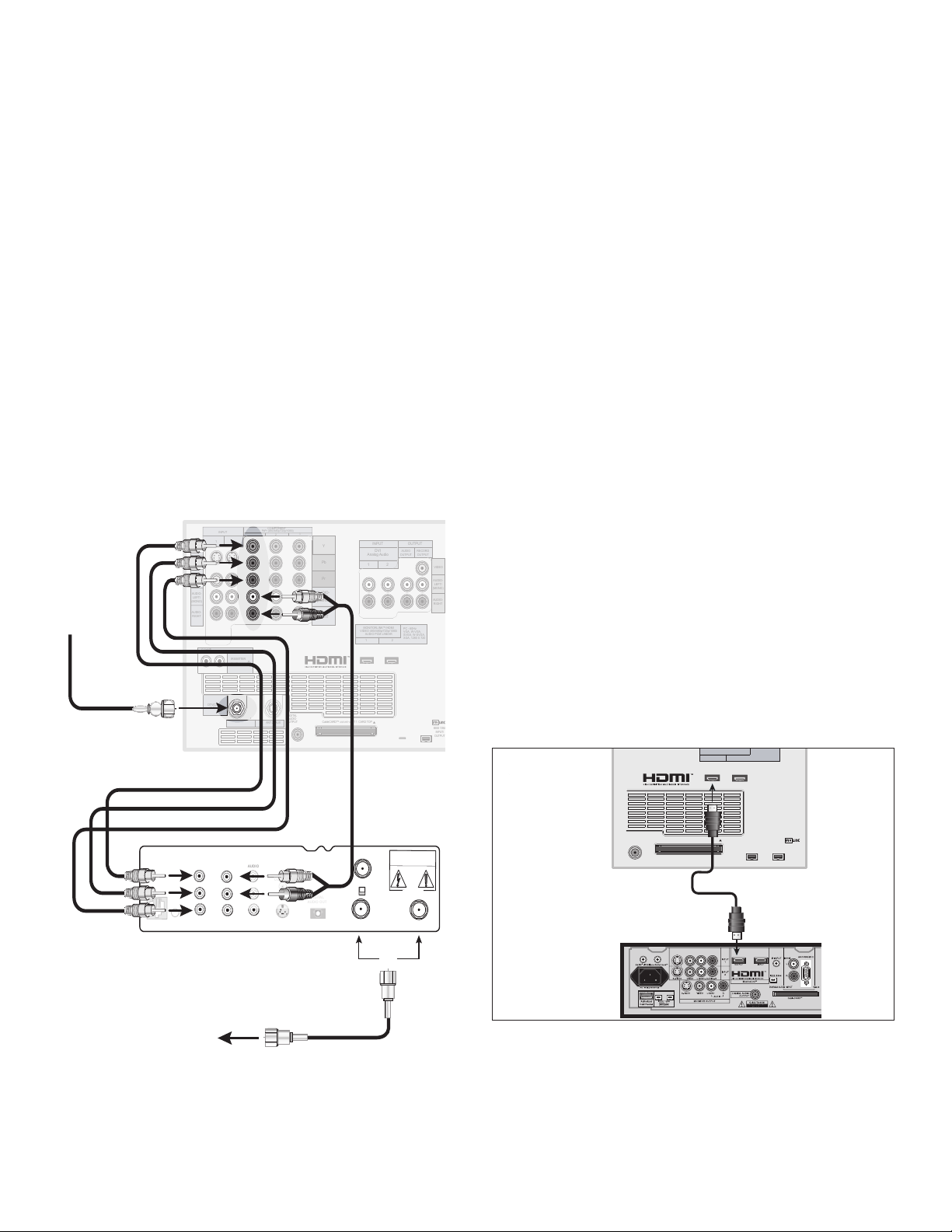
Connecting an HDTV Cable Box or Satellite Receiver with
COMPONENT
YPbPr (480i/480p/720p/1080i)
INPUT
1
2
S-VIDEO
VIDEO
AUDIO-
LEFT/
(MONO)
AUDIO-
RIGHT
DTV/CABLE/
VHF/UHF
ANT 1 / MAIN
ANT 2 / AUX
DIGITAL
AUDIO
OUTPUT
CableCARD™
USE WITH
ANT 1 CARD TOP
1
2
Y
Pb
Pr
AUDIO-
LEFT/
(MONO)
AUDIO-
RIGHT
OUTPUT
AUDIO
OUTPUT
RECORD
OUTPUT
DVI
Analog Audio
1 2
VIDEO
AUDIO-
LEFT/
(MONO)
AUDIO-
RIGHT
MONITORLINK™/HDMI
VIDEO 480i/480p/720p/1080i
AUDIO PCM LINEAR
1
2
IEEE 1394
INPUT/
OUTPUT
Net Command
IR EMITTER
¸
',INK
¸
INPUT
PC - 60Hz
VGA, W-VGA,
SVGA, W-SVGA,
XGA, 1280 X 720
7*%&0
:
1S
1C
47*%&0
7$3
$0/530-
1)0/&+"$,
3'
3&.05&
0655057
$)
$)
$"65*0/
3*4,0'&-&$53*$"-4)0$,
%0/0501&/
%*(*5"-
"6%*0065
4"5&--*5&*/
*/'30."/5
"6%*0
-
3
"6%*0
-
3
7*%&0
57#BDL1BOFM4FDUJPO
3FE
8IJUF
*ODPNJOH
"OUFOOBPS
$BCMF
)%573FDFJWFSXJUI
:1S1CDPOOFDUJPOT
5PBOUFOOB
DBCMFPSTBUFMMJUF
PS
3FE
8IJUF
CableCARD™ USE WITH ANT 1 CARD TOP
MONITORLINK™/HDMI
VIDEO 480i/480p/720p/1080i
AUDIO PCM LINEAR
1
2
IEEE 1394
INPUT/
OUTPUT
PC - 60Hz
VGA, W-VGA,
SVGA, W-SVGA,
XGA, 1280 X 720
DIGITAL
AUDIO
OUTPUT
)%.*%FWJDF
57#BDL1BOFM%FUBJM
Component Video
Connecting an HDMI Device
HDTV Cable Box or Satellite Receiver with Component Video
Figure 11
A coaxial splitter, RCA component video cables, and audio
cables are required. These are not included with the TV.
1. Connect the outside antenna, cable, or satellite to
ANT or SATELLITE IN on the cable box or satellite
receiver. See your device’s owner’s guide for
instructions and cable compatibility.
2. Connect the incoming terrestrial antenna or cable (not
satellite) to ANT-1 on the TV back panel (a coaxial
splitter, available at most electronic supply stores,
may be required to complete this installation).
HDTV Receiver to TV Back panel
• Y to Y
• Pr to Pr
• Pb to Pb
4. Connect L (left) and R (right) audio cables from the
DTV receiver to Component-1 AUDIO on the TV back
panel.
5. If you are using a satellite receiver, you must
change the input through NetCommand. Open the
NetCommand Connection for [device] screen (see
page 49) to make the change.
Note: To receive the benefits of a digital A/V receiver,
connect your cable box or satellite receiver’s digital audio
out to a digital input on your digital A/V receiver.
HDMI Device
Figure 12
An HDMI-to-HDMI cable is required. This is not included with
the TV. It may be available at your local electronics retailer
Connect an HDMI cable from the TV back panel to the
HDMI device output. HDMI devices provide video and
audio through this cable, so no other connection is
required. You can connect two HDMI devices to the TV
back panel through the HDMI connections.
Figure 11. Connecting an External HDTV Receiver with
Component Video Connections
3. Connect RCA-type cables from the YPrPb outputs on
30 Chapter 2. Connecting
the HDTV receiver to Component-1 on the TV back
panel, matching the correct connections:
Figure 12. Connecting an HDMI Device
Note: To use the benefits of digital surround sound from
th HDMI device, connect the digital audio output of the
HDMI device directly to the A/V receiver.
Page 31

1$XJUI)%.*0VUQVU
57#BDL1BOFM
COMPONENT
YPbPr (480i/480p/720p/1080i)
INPUT
1
2
S-VIDEO
VIDEO
AUDIO-
LEFT/
(MONO)
AUDIO-
RIGHT
DTV/CABLE/
VHF/UHF
ANT 1 / MAIN
ANT 2 / AUX
DIGITAL
AUDIO
OUTPUT
CableCARD™ USE WITH ANT 1 CARD TOP
1
2
Y
Pb
Pr
AUDIO-
LEFT/
(MONO)
AUDIO-
RIGHT
OUTPUT
AUDIO
OUTPUT
RECORD
OUTPUT
DVI
Analog Audio
1 2
VIDEO
AUDIO-
LEFT/
(MONO)
AUDIO-
RIGHT
MONITORLINK™/HDMI
VIDEO 480i/480p/720p/1080i
AUDIO PCM LINEAR
1
2
IEEE 1394
INPUT/
OUTPUT
Net Command
IR EMITTER
¸
',INK
¸
INPUT
PC - 60Hz
VGA, W-VGA,
SVGA, W-SVGA,
XGA, 1280 X 720
)%.*
Connecting a Computer with an HDMI or DVI Monitor Output
"6%*0065
-&'5
3*()5
1$XJUI%7*0VUQVU
$6)/54
57#BDL1BOFM
COMPONENT
YPbPr (480i/480p/720p/1080i)
INPUT
1
2
S-VIDEO
VIDEO
AUDIO-
LEFT/
(MONO)
AUDIO-
RIGHT
DTV/CABLE/
VHF/UHF
ANT 1 / MAIN
ANT 2 / AUX
DIGITAL
AUDIO
OUTPUT
CableCARD™ USE WITH ANT 1 CARD TOP
1
2
Y
Pb
Pr
AUDIO-
LEFT/
(MONO)
AUDIO-
RIGHT
OUTPUT
AUDIO
OUTPUT
RECORD
OUTPUT
DVI
Analog Audio
1 2
VIDEO
AUDIO-
LEFT/
(MONO)
AUDIO-
RIGHT
MONITORLINK™/HDMI
VIDEO 480i/480p/720p/1080i
AUDIO PCM LINEAR
1
2
IEEE 1394
INPUT/
OUTPUT
Net Command
IR EMITTER
¸
',INK
¸
INPUT
PC - 60Hz
VGA, W-VGA,
SVGA, W-SVGA,
XGA, 1280 X 720
%7*UP)%.*$BCMF
)%.*
"VEJP
Computer with an HDMI Monitor Output
Figure 13
An HDMI-to-HDMI cable is required. This is not included with
the TV. It may be available at your local electronics retailer
Connect an HDMI cable from HDMI 2 on the TV
back panel to the PC’s HDMI output. HDMI devices
provide video and audio through this cable, so no other
connection is required.
Computer with a DVI Monitor Output
Figure 14
A DVI-to-HDMI cable or DVI/HDMI adaptor and HDMI cable and
audio cables are required. These are not included with the TV.
They may be available at your local electronics retailer.
1. Connect the DVI-to-HDMI cable (recommended) (or
DVI/HDMI adaptor with an HDMI cable) from the PC
DVI output to HDMI 2 on the TV back panel.
NOTE: If you are using a DVI/HDMI adaptor, it is
important to connect the adaptor to the DVI device
for best performance.
2. Connect a set of audio cables from AUDIO OUT on
the PC back panel to INPUT/DVI Analog Audio 2 on
the TV back panel. The red cable connects to the R
(right) channel, and the white cable connects to the
L (left) channel.
NOTE: The HDMI connection supports copy protection
(HDCP). Some devices require connecting to an
analog input first, in order to view on-screen menus
and select DVI as the ouput. Please review your
equipment instructions for DVI connectivity and
compatibility.
Figure 13. Connecting a Computer with an HDMI Monitor
Output
To view PC video on the TV, you must activate
the PC option in NetCommand. You can
do this during initial NetCommand setup
(in the Device Setup screen), or at any time
afterwards by using the NetCommand Add
function.
Chapter 2. Connecting 31
IMPORTANT
CAUTION: To ensure continued FCC
compliance, the user must use a
shielded video interface or HDMI cable
with bonded ferrite cores at both ends
when using the PC input.
Figure 14. Connecting a Computer with DVI Monitor
Output
Page 32

Connecting the IR Emitter NetCommand®
%* (* 5" -
46330 6/%
4
$)
57CBDL
QBOFMEFUBJM
0UIFS"7EFWJDF
"7SFDFJWFS
IR Emitter NetCommand®
Figure 15
An IR emitter cable is included with the TV.
The emitters connected to these jacks are used by the
NetCommand system to control other devices such as
VCRs, DVD players, Cable boxes and Satellite receivers.
1. Connect the plug end of the supplied IR Emitter
Cable to either one of the IR Output NetCommand
jacks on the TV back panel.
2. Run the cable for each of the emitter ends under,
along side or over the top of each device to be
controlled to the area of the front where the remote
control sensor is located.
3. Place the emitter end in front of the remote control
sensor of the device to be controlled. The emitter
bulb should face the remote control sensor. This
bulb emits infrared light in a cone shaped pattern.
The bulb needs to be placed far enough from the
remote control sensor to allow the cone pattern to
include the sensor.
• With some devices, the emitter works better facing
downward from the top of the device. Some
experimentation may be needed.
• The emitter end being used can be secured in place
using double stick tape.
• If you are not going to be using all emitter ends, place
the unused ends behind the devices so that they
cannot send signals to the remote control sensors.
The remote control sensor is usually behind the
plastic window of the front display panel. It is
sometimes visible when you look through the
display plastic using a flashlight and is normally a
round or square cutout behind the plastic. If you
cannot see the sensor and the device’s Owner’s
Guide does not specify the location, you can find it
by using the device’s remote control.
a. Hold the remote about 1/2 inch from the front of
the device. Starting from one end of the display
window plastic, press the POWER button.
b. If the device does not respond, move the remote
control 1 inch toward the center and try again.
c. Repeat this until the device responds.
d. Note this location and then start over from the
other end of the display window plastic, repeating
until the device responds again.
The remote control sensor will be somewhere
between these two positions. This is usually
enough accuracy for the placement of the IR
emitters.
Figure 15. Connecting IR Emitter NetCommand
IMPORTANT
If a single emitter end can be placed in a
position that will operate more than one device,
do not use a separate emitter end for the
additional device. A single device receiving
remote control signals from too many emitters
or remote controls may not respond at all.
32 Chapter 2. Connecting
Page 33

Connecting Compatible IEEE 1394 Devices
Compatible IEEE 1394 Devices
It is possible to connect devices to the TV that have IEEE
1394 connectors but are not compatible with the TV or with
the NetCommand® control system. Areas of compatibility
to consider are:
1. Digital Video Signals
The TV is able to decode MPEG2 video. Other types
of digital video, such as DV video provided by some
camcorders, must be decoded by the source device
and sent to the TV as analog video, or S-video. If the
camcorder uses a compatible digital control system,
the IEEE 1394 cable can still provide control for the
camcorder while the TV is viewing the analog video or
S-Video signals.
2. Digital Audio Signals
When received with video signals, the TV is able to
decode Dolby Digital signals and MPEG audio signals.
Other types of digital audio as provided by some digital
recording devices, such as MP3 audio and DTS audio,
cannot be decoded by the TV when received over IEEE
1394
The TV may not be able to pass incompatible digital
audio signals on the coaxial digital audio output,
however these signals may pass on the IEEE 1394 cable
to other devices.
3. Digital Control Signal
The TV is able to act as the control center for IEEE 1394
audio/video devices, such as VCRs, A/V Discs, tuners,
cable boxes and amplifiers that are compatible with the
following IEEE 1394 control standards.
• EIA-775 is designed for tuning devices such as cable
boxes allowing the device to send simple graphics.
However, this standard does not allow the TV to
control the cable box by IEEE 1394.
When Connecting IEEE 1394 Devices
• Do not loop the last device in the chain back
to the TV. When the device chain is looped,
the TV may not be able to work with the other
devices.
• Place devices that have only a mechanical (two-
position) power switch at the end of the chain
or leave the power switch in the On position.
When turned Off, IEEE 1394 signals may not
be able to pass through the device to other
devices.
• Place devices with the slowest communication
speed at the end of the chain. Sometimes
the communication speed will be marked
near the IEEE 1394 connector with an “S”
number. The higher the number, the faster
the communication speed. This TV has a
communication speed of S400. Devices with
slow communication speed can interfere
with IEEE 1394 signals from faster devices.
When using NetCommand to set up a digital
recording between a faster and slower device,
the slower device should be the source and the
faster device should be the recorder.
• Do not use an IEEE 1394 cable longer than 15
feet between each device.
• This TV is an IEEE 1394a device. It can be used
with a 1394b system when an IEEE 1394a to
1394b convertor is used. 1394b systems enable
longer distance and multi-room applications.
• AV/C (Audio Video Control) is designed to provide
basic controls such as play, stop, channel selection
and volume, as appropriate for the device.
Some devices may be a combination of two or more
types of devices. For example, there may be a
recording device that is also a tuning device. Each
portion of the device is called a sub-unit. When you
select a device on the Device Selection menu that
has sub-units, a pop-up menu will appear so you can
select which sub-unit section you wish to use.
Chapter 2. Connecting 33
Page 34

6 pin to 4 pin adaptor
4 pin connector
6 pin connector
Digital
DVD
Digital
VCR
TV
Digital
DVD #1
Digital
VCR #1
D
I
G
I
T
A
L
S
U
R
R
O
U
N
D
S
C
H
Digital DVD #2
Digital VCR #2
Other 1394 Device #2
1394
Monitor
Digital
VCR #3
Other
1394 Device #1
TV
Connecting Compatible IEEE 1394 Devices, continued
Connection Styles
There are two different connection styles that can be
used when connecting IEEE 1394 devices. Use the
style that fits your network of audio/video products.
Direct Device-To-Device Style
The IEEE 1394 offers you the capability to chain
devices, unlike previous audio and video connections
where you had to individually connect each device
directly to the TV. For example, you can connect your
D-VHS to your 1394 DVD Player and then connect the
1394 DVD Player to the TV. The resulting IEEE 1394
chain will allow you to add more devices to the chain.
You will be able to see each video device on the TV’s
Device Selection Menu and send information from
any IEEE 1394 device to other compatible devices.
Hub Connection Style
4-Pin Style vs. 6-Pin Style Connectors
There are two different types of connectors used for
IEEE 1394 terminals and cables, a 4-pin and a 6-pin
style.
The 4-pin connector sends
digital audio signals, digital video
signals and digital control signals
back and forth between devices.
Your TV has three 4-pin type
connection jacks available. One is
on the front panel and two are on
the back.
The 6-pin connector is capable
of sending the same digital audio,
video and control signals as the
4-pin connector, but the 6-pin
connector is also able to send low
voltage electrical power. This TV
does not have 6 pin connectors.
The purpose of this low voltage electrical power is to
provide the needed operating power to a device that
is not connected directly to the household AC power
such as a camcorder. A device with a 6-pin connector
can send this electrical power to another device, or
receive electrical power from another device, or simply
use a 6-pin connector without using the two additional
pins.
The IEEE 1394 also offers you the capability to
connect your devices using the TV as a hub within
the audio/video network. Each device can send
information, which may include audio and video, to
any other device in the network.
34 Chapter 2. Connecting
A 6-pin connector cannot be
connected directly to a 4-pin
jack, and vice versa. To connect
a 6-pin device to a 4-pin device,
you will need to obtain a 6-pin to
4-pin adaptor or adaptor cable.
These cables are available from
electronic and computer stores.
When connecting a 6-pin device (such as a camcorder)
to the TV, (if it is designed to receive electrical power
from another 6-pin device) you will need to connect
the camcorder directly to the household AC, or use the
camcorder’s battery for power. If this is not possible,
then the camcorder will need to be connected directly
to another 6-pin device in the network that can provide
the electrical power.
Page 35

Helpful Hints
Q. My VCR (or other device) does not have two sets of stereo audio outputs. How can I connect this device’s
audio to both the TV and the A/V Receiver?
A. Connect the single set of stereo audio outputs to the TV only. Use Edit NetCommand® to change the setup of this
device. In the Connection screen of “Change” make sure both audio and video for the TV input are check marked
and neither the audio or the video for the AVR input are check marked. This will allow the NetCommand system to
use the TV outputs to transfer the device’s audio to the A/V Receiver. See Edit NetCommand in the next chapter for
details.
Q. I have both the TV stereo audio output and TV digital audio output connected to the same input
designations on my A/V Receiver. How do I switch between analog audio and digital audio?
A. In most setups, analog audio is also output as digital audio, so no switching is required, and there is no need to
connect the analog output. In some circumstances, however, you may also need analog audio from the TV. For
example, MP3 audio is only output in analog format, so you must connect the TV’s analog AUDIO OUTPUT to the
A/V Receiver if you want to hear MP3 audio through the A/V receiver. Refer to your A/V Receiver user’s guide to
find out how analog/digital audio switching works.
• If your A/V Receiver’s remote control has an Analog/Digital Audio key, you can use the GUIDE key with the
following models to control switching:
Mitsubishi M-VR900 Integra DTR-9.1
Denon AVR-2700 Kenwood VR-2080
To make the switch, press the Device key on the TV’s remote control, and from the Device Selection menu,
press the Audio key. Then, with the A/V Receiver highlighted, press the GUIDE key to make the switch.
• If you have some other A/V Receiver model, use the TV’s learn function to learn the analog/digital audio code
for the GUIDE key. Follow the instructions above for using the GUIDE key.
• If your A/V Receiver has an Analog/Digital selection key on the front panel only, and not on the remote, then
your only option is to use that key to perform switching.
Q. The front panel of my A/V Receiver is too tall or too convex for the IR emitter signal to reach the remote
control sensor of the A/V Receiver. What can I do?
A. There are several possible solutions.
1. Mount the IR Emitter on the top, front edge of the A/V Receiver over the remote control sensor. Use tape to
secure it in place.
2. Mount the IR Emitter on the underside of the shelf above the A/V Receiver (if the A/V Receiver is in a cabinet).
Use double sided tape to secure it in place.
3. Some small stick-on emitters from other manufacturers may be compatible with this TV’s IR Emitter jacks.
These may be used instead of the supplied IR Emitters.
Q. I occasionally need to see the menu from my A/V Receiver. How can I connect it to the TV for this purpose?
A. You can connect the video output of the A/V Receiver to an unused input on the TV. Then use Edit NetCommand
to “Add” this as an “Other” device, not an A/V Receiver. On the “Connection” screen, indicate which TV input was
used and check mark the video box. Make sure the TV input audio box and both the audio and video boxes for
the AVR input are not check marked. You should also name this device so you can easily identify it on the Device
Selection Menu. You can also use Input 3 on the front panel.
Q. I have a high definition receiver I would like to connect and it also has an S-video output I would like to be
able use as well. Is there any way to connect this receiver both ways?
A. Yes, this item will appear twice in the Device Selection Menu. Just add this unit once using the Component-1 and
once using one of the S-video inputs. Make sure you indicate that this is the same manufacturer for both. We
suggest that you connect stereo audio outputs with the S-video to the TV so that you do not need to use two inputs
on the A/V Receiver. If this is a NetCommand compatible HDTV receiver and HD or SD outputs can be switched by
remote control, see Edit NetCommand in the next chapter for NetCommand control of this feature.
Chapter 2. Connecting 35
Page 36

Page 37

Chapter . . .
NetCommand® Setup and Editing
NetCommand® Introduction . . . . . . . . . . . . . . . . . . . . . . . . . . . 38
Using the Remote Control with NetCommand® . . . . . . . . . . . . . 39
NetCommand® Setup On-Screen Buttons . . . . . . . . . . . . . . . . . . 40
3D Graphical Menu System . . . . . . . . . . . . . . . . . . . . . . . 41
NetCommand® Initial Setup . . . . . . . . . . . . . . . . . . . . . . . . . . . 42
3
Edit NetCommand®: Add an A/V Receiver . . . . . . . . . . . . . . . . . 45
Edit NetCommand®: Add Devices . . . . . . . . . . . . . . . . . . . . . . . 48
Edit NetCommand®: Change or Delete Devices . . . . . . . . . . . . . 52
Page 38

NetCommand® Introduction
Welcome To NetCommand
NetCommand makes your TV the heart of your Home Theater
NetCommand® is an intelligent control system that makes your Mitsubishi TV the heart of your home theater. With
NetCommand, the TV sends signals to the other devices in the system, telling them to play, record, change inputs,
adjust volume, change channels and many more functions. All of this is accomplished with one remote control and
without changing control layers.
IR Learning and IEEE 1394 Support
The IR “Learning” feature of NetCommand allows the TV to learn the remote control signals for new devices that the TV
is not preprogrammed to operate. NetCommand® also includes the capability to control IEEE 1394 devices by sending
control signals on a FireWire® cable.
Using NetCommand is completely optional
When you first turn on the TV, the NetCommand Setup Wizard launches. If you decide to use NetCommand, follow
the on-screen instructions. If you choose not to use it right away, simply quit the Setup Wizard and NetCommand will
remain inactive. Later, if you decide to use NetCommand, you can easily access the Setup Wizard.
NetCommand and Levels of Control
When you set up NetCommand, you decide how much control you want the TV to have over your home theater system.
You have the choice of performing a basic, limited, or complete NetCommand setup.
• Basic Setup
In a basic setup, NetCommand will:
◊ automatically switch to the correct TV input when you want to view programming from a different device. All
you do is select the device from the on-screen device selection menu. This saves you from having to search for
the correct input every time you want to change devices. Unused inputs are automatically deactivated so that
you don’t see them in the menu.
◊ show an on-screen icon for each device connected to the TV so you always know what devices are available.
Note that with a basic setup, you still need to use the remote control specific to each device.
• Limited Setup
In a limited setup, you get the benefits of the basic setup plus NetCommand control over the specific devices you
have chosen. Use this type of setup if you:
◊ only want NetCommand to control a few devices, such as the TV, a playback device (like a DVD player), and a
cable box. With this setup, you can use the TV’s remote to control these devices.
◊ want to use TV Guide On Screen® to control your cable box and VCR and/or A/V disc. After performing this
setup, you can use the TV’s remote to control these devices.
• Full Setup
Perform a full setup if you want NetCommand to:
◊ control a surround sound A/V receiver.
◊ automatically change input selections for the A/V receiver.
◊ control all devices with the TV’s remote, including the A/V receiver.
NetCommand Helps You Manage Your Home Theater
With the NetCommand Review screen you can:
• view a summary of all devices connected to the TV and the input used for each device.
• deactivate or turn off unused input connections; reactivate or turn them on.
If you need to change your setup, the NetCommand sub-menu lets you easily
• add new devices.
• deleted devices you have disconnected.
• change device and input selections.
38 Chapter 3. NetCommand Setup and Editing
Page 39

Using the Remote Control with NetCommand®
Below is a list of several manufacturers’ devices tested and shown to be compatible with NetCommand. These devices
can be controlled without changing the setting of the remote control from TV to another product. NetCommand may be
able to operate additional models since many manufacturers use the same control signals to operate some or all of the
models they offer. This chart lists only the models that have been tested with NetCommand. The NetCommand Learning
feature is able to learn the remote control signals of most Audio Video devices. For devices not listed in the table, or
if your device does not operate using the same remote control as the models listed below, use the learning feature by
selecting “Other” at the [Device] screen. See the Edit NetCommand section of this Guide.
NOTE: There are many different types of remotes and not all of them may be compatible with the learning feature. Bright
light near the TV screen can also adversely affect the learning feature. If it is not possible to learn a device, you will need
to use the original remote control of the device, or program the TV remote to operate these devices in the traditional
manner.
NetCommand Pre-Memorized Devices
DEVICE
A/ V receiver Cable Box SAT Satellite
M
Mitsubishi M-VR800,
A
Bose Lifestyle® 28 Lifestyle® 28
N
Denon AVR-2700
Echostar 6000
U
Funai F260LA
F
General
Instruments
A
Hitachi DV-P415U VT-FX665A
C
Hughes HIRD-E45,
T
Integra DTR-9.1 DPS-9.1
U
Jerrold Not
R
JVC XV-S65GD HR-VP 650U
E
Kenwood VR2080
Marantz SR8200
R
Microsoft XBox™ (requires the DVD kit from
Motorola DCT2244
Panasonic TU-HDS20 DVD-A310 PV-8662
Philips VR620CAT
Pioneer VSX-D557,
RCA DRD480RE,
Rotel RSX-1065
Scientific Atlanta 8600
Sharp VC-H810U
Sony STR-DE825 SAT-A55 DVP-S500D, PlayStation® 2
Toshiba DTS-3000 SD-9200, SD-5109 W-717
Yamaha RX-V2095,
Zenith DTV1080
M-VR900
CFT2200
specified
VSX-49TX
RX-V2200
Receiver
SR-HD5 DD-6000, DD-8020 HS-U795, HS-
HIRD-E86
DTC-100
DVD Player VCR
U778
Microsoft)
DV-414
SLV-778HF
(Playstation® 2 requires the DVD
Remote Controller kit from Sony; DVD
Player software disc version 2.10)
DVD-S520, DVD-C996
Chapter 3. NetCommand Setup and Editing 39
Page 40

NetCommand® Setup On-Screen Buttons
To use the TV’s NetCommand feature, you need to provide some detailed information during the setup of your
Mitsubishi TV. You must define the manufacturer of the devices that are connected to the television, or learn the IR
code remote control signals for the device connected. For each device, the input to the TV and A/V receiver, and the
names for the device are pre-set during Initial NetCommand setup. You may change those inputs or names using
the Edit NetCommand or Learn screens. The buttons described below will help you navigate the screens.
On your remote control, the ADJUST or buttons allow
you to navigate left and right to different selections on the
screen. The ADJUST or buttons allow you to:
• Change the radio button
• Change current text box selection
• Navigate up and down on the screen
The ENTER button allows you to:
• Confirm the selected character when naming a
device
• Add or delete check marks in check boxes
• Select on-screen buttons to change screens
Text Box
Press ADJUST or to make a selection.
Check Box
Control Buttons
Much like the software on your computer, you will use
graphic buttons to navigate through the NetCommand
Setup screen. Highlight the button and press ENTER to
select the function.
<Back Button
Use the <Back button to navigate back to the previous
screen.
Next> Button
Use the Next> button to navigate forward to the next
screen.
Cancel Button
Check marks indicate the item or input is added or turned
On. Press ENTER when the Check box is highlighted to
add or delete a check mark. When viewing the Review
screen, a Check box reflects which devices are turned
On or Off, or connected to the TV.
Radio Buttons
The setting changes when one of the choices is
highlighted.
40 Chapter 3. NetCommand Setup and Editing
The Cancel button will cancel out any changes you
are currently making without saving them into memory.
When you select the Cancel key, NetCommand will
prompt you to confirm that you want to cancel the
changes you are currently making. If you select Cancel
during Initial Setup, you can setup NetCommand later by
selecting the NetCommand menu, then choosing Initial.
Page 41

108&3
)0.&
27
70-6.&
*/'0
&9$)
&/5&3
57.&/6
%&7*$&
.&/6
7$)*1
'03."5
1*1$)
427
%&7*$&
4-&&1
7*%&0
"6%*0
.65&
$)"//&-
"%+645
1*1
1*1%&7*$&
$"/$&-
57
"6%*0
$"#-&%#4%57 %7%
7$3
(6*%&
46#
1"(&
3D Graphical Menu System
Your TV also has Mitsubishi’s exclusive 3D Graphical on-screen operating system, which provides
on-screen information for menu choices and changes, using the TV’s remote control.
Menu Screens
A picture (icon) will be highlighted on the
menu screen when selected with the ADJUST
arrows. You may then make changes within
the menu or access sub-menus, if available.
You can also access sub-menus from a button.
Sometimes when you select a button, an
automatic function begins.
The system includes the following special
features:
• The currently selected icon or button is
highlighted with a yellow outline; the text color is
yellow.
• On-screen instructions, shown in the message
line at the bottom of the menu, provide feature
selection and adjustment information.
• Some on-screen menu options must be set
before other options are available.
Remote Control Buttons
The following buttons on your remote control help you
navigate within the system :
1. ADJUST or to select the menu item you want to
change.
2. ADJUST or to change the settings.
3. ENTER to enter into a menu, start an automatic
function or select a check box.
4. TV MENU to display the main menu or move back
one menu screen at a time.
5. CANCEL to clear a setting or stop an automatic
function.
6. HOME to exit all menus and return to TV viewing.
3
2
5
1
Main Menu: This screen will always be the first screen that
appears when you press the remote’s TV MENU button.
4
1
2
6
Press ADJUST or to change text boxes. Some
text boxes have preset labels. Other boxes allow you
to select letters, numbers or characters to customize
names.
Chapter 3. NetCommand Setup and Editing 41
Page 42

NetCommand® Initial Setup
The initial setup screens that appear when you first
power on your new Mitsubishi TV guide you through
setup of NetCommand and the TV Guide On Screen®
system. Most IR remote control signal formats can be
learned by NetCommand.
Welcome Screen
Figure 1
When you first turn on your TV, the NetCommand
Welcome screen displays and asks you to select either
English or Spanish as the language for the on-screen
menus. The default language is English. To change
Language later, select Setup in the Main Menu. Selecting
Cancel at this screen will cause the default language
(English) to be selected.
Figure 1. Welcome screen
If the NetCommand Setup is cancelled before it’s
completed, you can restart the NetCommand setup
from the Setup Reminder screen (see below) or by
doing the following:
1. Press TV MENU on the remote control to display
the TV Main menu.
2. Select NetCommand. The available options will be
Add, Review, Guide or Initial. Change and Delete
will be grayed out.
3. Press ADJUST to select Initial.
4. Press ENTER. The Device Setup screen (shown
on the next page) displays.
Setup Reminder
Figure 3
This screen only appears if you did not set up
NetCommand when the TV was first turned on. The
Setup Reminder screen displays for the next six times
you power on the TV.
If you would like to set up NetCommand and/or the
TV Guide On Screen system, select Next and press
ENTER. If you do not wish to set up NetCommand
and/or the TV Guide On Screen system, then select
Cancel and press ENTER.
NetCommand (Information) Screen
Figure 2
The NetCommand (Information) Screen describes how
to start or delay the initial NetCommand and TV Guide
On Screen setup. This screen displays automatically the
first time you power On your new TV, after the Welcome
screen.
Figure 2. Information screen
Select Next> and press ENTER to start the initial setup.
42 Chapter 3. NetCommand Setup and Editing
Figure 3. Setup Reminder screen
IMPORTANT
You may use your TV without setting up
NetCommand or the TV Guide On Screen®
system. To set up at a later time, choose the
NetCommand menu from the Main menu,
then select Initial. The TV Guide On Screen
system is set up from the NetCommand
menu.
Page 43

NetCommand® Initial Setup, continued
Device Setup Screen
Figure 4
If the devices connected to the TV are already in
NetCommand memory, you can quickly select them
at this screen. Press ADJUST or to move to each
device type. Press ADJUST or to select the
manufacturer. Select “Other” if the manufacturer is not
listed. Later, you can use the Change setting in the Edit
NetCommand menu to learn the remote control signals
for this device. Select “None” for device types that are
not connected.
For the A/V Receiver, if the manufacturer is not listed, you
cannot select “Other”. Instead, select “None”. Later, you
can use the “Add” feature in the NetCommand menu to
have the TV add and learn the remote control signals for
this device.
If you have a camcorder connected, check the
Camcorder box. NetCommand will not be able to
control it, but will reserve the front input to use with
the camcorder. Check the PC box if you have a PC
connected. After completing your choices, select Next>
and press ENTER.
TV Guide On Screen® System Setup
Figure 5
The TV Guide On Screen option allows you to select
whether you want to enable the TV Guide On Screen
system and, if so, which devices you want to include.
In order to get the correct listings for your area, you
will need to enter your five-digit ZIP code.
You can select one over-the-air source and one cable
source for TV Guide On Screen. If, however, you have
multiple cable sources, the channel-number assignments
may not match up correctly. See the table below for the
preferred connection combinations.
If One Source Is: The Other Source Can Be:
Ant-1 over-the-air
reception
Ant-2 over-the-air
reception
For detailed information on using the TV Guide On
Screen system, please see the separate TV Guide On
Screen Interactive Program Guide User’s Manual.
• Cable box (on any input)
• Ant-2 channels memorized
via cable
• Cable box (on any input)
• CableCARD™ on Ant-1
• Ant-1 channels memorized
via cable
Figure 4. Device Setup screen
Note: If you selected “Other” for any of the
device names, you can direct the TV to “Learn”
the connected device by following the Edit
NetCommand instructions. For many device
types, non-listed models will operate in the same
way as the listed models and you can still use the
pre-loaded setting.
IMPORTANT
NetCommand must be set up and the IR
emitters properly placed for your cable box
and VCR so the TV Guide On Screen system
can control these devices.
Chapter 3. NetCommand Setup and Editing 43
Figure 5. TV Guide On Screen
Note:
• Inputs to TV Guide On Screen can include:
- Only one over-the-air source
- Only one cable source
• If your cable box is connected using HDMI or
IEEE-1394, we recommend you also connect an
antenna.
• If your cable box is connected to Component 1 or 2,
you should make sure the box is set to send analog
channels as 480i. If this is not possible, add an
antenna.
Page 44

NetCommand® Initial Setup, continued
Review Screen
Figure 6
After you have made your device choices, the Review
Screen will display. It is important to review the settings
to ensure that they are correct. If necessary, you can
use <Back to return to the Device Setup screen to make
changes.
Figure 6. Review screen
Note: The Review screen lists the TV input and A/V
receiver input used with each device. You must
correctly identify the inputs you used when you
connected the devices. If you have not connected
your devices, write down these inputs as a guide. If
you cannot use these inputs, or if you would like to
change the name of a device, use the instructions in
Edit NetCommand to make necessary changes.
Note: If you select Next> on the Review screen, all
selections made are finalized.
Finish Screen
Figure 7
To complete the NetCommand setup, select Finish
from the Finish screen.
If you wish to change any of the pre- configured
inputs or names for the devices, or add devices not in
the pre-configured setup, select Edit to display Edit
NetCommand menu.
If your A/V receiver was not listed, select Edit to add
the AVR and then assign all devices to new AVR inputs.
Figure 7. Finish screen
It may still be necessary to memorize the available
channels for Antenna-1 (and Antenna-2, if used).
You may do that by going to the TV Main menu and
selecting Setup. Instructions to memorize channels are
found in the Setup menu section.
On the Review screen, adding or deleting check marks
will turn the adjacent devices or inputs On or Off. 1394
device names only appear on the Review screen when
the devices are connected to the TV.
44 Chapter 3. NetCommand Setup and Editing
Page 45

Edit NetCommand®: Add an A/V Receiver
A/V Receiver Screen
Figure 8
If your A/V Receiver manufacturer was not listed, and you
selected “None” during the initial NetCommand setup,
you may add the A/V Receiver and have NetCommand
learn its remote control’s functions. Either select Edit
from the Finish screen or, if you have finished the initial
setup, go to the Main menu, select NetCommand, then
press ENTER. The Edit NetCommand screen will display.
Select Add.
However, NetCommand will not be able to control
this device. Later you may use the “Change” option
in the NetCommand menu to learn the remote control
signals.
After selecting Next>, the screens that follow are: the A/V
Receiver Input screen (Figure 8), Name screen (Figure 11),
Audio Output to AVR screen (Figure 12), ending with the
Finish screen (Figure 13).
Figure 8. A/V receiver screen
Choose ONE of these options:
• Select a recognized manufacturer. The model
number optimized for NetCommand will display at
the bottom of the screen. If a number follows the
manufacturer’s name, (example: Mitsubishi 1), this
indicates additional models are optimized for that
manufacturer. For many device types, non-listed
models will operate in the same way as the listed
models and you can still use the pre-loaded setting.
After selecting Next>, the screens that follow are:
the Name Screen (Figure 12), Audio Output to AVR
screen (Figure 13), ending with the Finish screen
(Figure 14).
• Select “Other”, then highlight “Learn” and press
ENTER. This will allow you to have NetCommand
learn the remote control signals of this new device.
After selecting “Learn” and pressing ENTER, the
screens that follow are: the A/V receiver Inputs
screen (Figure 9), A/V Receiver Input Learn screen
(Figure 10), A/V Receiver Learn screen (Figure 11),
Name screen (Figure 12), Audio Output to AVR
screen (Figure 13), ending with the Finish screen
(Figure 14).
A/V Receiver Inputs
Figure 9
If you select “Other” as the manufacturer and then
“Learn,” you will see the A/V Receiver Input screen. After
selecting the number of inputs, this screen will not appear
again.
Depending on your A/V Receiver’s capability, you may
connect up to seven A/V inputs. Select the number of
inputs by pressing ADJUST or .
If the number of connected inputs changes, you will need
to delete the A/V receiver through Edit NetCommand and
add it again, as described above.
Figure 9. A/V receiver Input screen
• Select “Other,” skip Learn and select Next>. This
will allow the device to appear and will allow
NetCommand to switch inputs to use this device.
Chapter 3. NetCommand Setup and Editing 45
Page 46

Edit NetCommand®: Add an A/V Receiver, continued
A/V Receiver (AVR) Input Learn Screen
Figure 10
NetCommand can now learn the remote control signals
used to select each input on the A/V receiver.
1. Press ADJUST or on the TV remote to select the
check box for each function to be learned.
2. Press ENTER and the function name will begin to
flash to confirm the ready-to-learn status.
3. Press the button on the A/V receiver’s remote control
that corresponds to the selected function. A check
mark will appear and the function name will stop
flashing. This confirms the signal learned status.
4. To test the learned command, press ENTER on the TV
remote. The A/V receiver will perform the selected
function. The A/V receiver needs to be turned on
and the IR emitters properly placed for the test to be
successful (see page 32 for IR emitter placement).
5. To customize the input names, press ADJUST to
move to the Input Name text box and then press
ADJUST or and ENTER to select each letter of
the name. These names will appear on the Review
screen as the A/V receiver’s input names, and should
match the names the A/V receiver shows in its own
display.
A/V Receiver (AVR) Learn Screen
Figure 11
1. Press ADJUST or on the TV remote to select the
check box for each function to be learned.
2. Press ENTER and the function name will begin to flash
to confirm the ready-to-learn status.
3. Press the button on the A/V receiver’s remote control
that corresponds to the selected function, A check
mark will appear and the function name will stop
flashing. This confirms the signal learned status.
4. To test the learned command, press ENTER on the TV
remote. The A/V receiver will perform the selected
function. The A/V receiver needs to be turned on
and the IR emitters properly placed for the test to be
successful (see page 32 for IR emitter placement).
5. Repeat for each function to be learned.
6. To erase a learned function, highlight the check box
for that function and press CANCEL.
7. When the function signals have been learned, press
ADJUST to select Next> and move to the Name
screen.
6. To erase the learned input signal, highlight the check
box for that input and press CANCEL.
7. Repeat for each connected input.
8. When the input selection signals have been learned
and the inputs named, press ADJUST to select
Next> and move to the A/V receiver Learn screen.
Figure 10. A/V receiver Input Learn screen
Figure 11. A/V receiver Learn screen
IMPORTANT
When learning remote control signals, point
the device’s remote at the TV screen
46 Chapter 3. NetCommand Setup and Editing
Page 47

Edit NetCommand®: Add an A/V Receiver, continued
Name Screen
Figure 12
The Name screen allows you to change the default name
for the A/V receiver to a custom name of up to eight
characters (including a blank space), selecting from
letters, numbers, and nine different characters. Using
the TV’s remote, press ADJUST or to select each
letter, then press ENTER to move to the next position.
Press CANCEL to delete the current letter and move back
one character position. When in the first position, the
CANCEL button will return the name to the default name.
Figure 12. Name screen
Finish Screen
Figure 14
To finalize your selections and complete the A/V
receiver setup, select Finish from the Finish screen.
Note: If you connected the audio output of other
devices directly to the A/V Receiver, you must use
the “Change” function of the Edit NetCommand
menu and select each device to assign the correct
A/V Receiver input to be used with each device.
Figure 14. Finish screen
Audio Output to AVR Screen
Figure 13
Use this screen to select which A/V Receiver input is
connected to AUDIO OUTPUT on the TV back panel.
Press ADJUST to select Next> and move to the Finish
screen.
Figure 13. Audio Output to AVR screen
Note: To change any of the inputs or names for the
devices, or add devices not included in the initial
settings, select Edit to display the Edit NetCommand
menu.
IMPORTANT
NetCommand does not allow you to delete
an A/V receiver or change the connections
for a device (such as the TV or a DVD player)
if the A/V receiver is currently being used.
To delete or change the A/V receiver
connections, you must be listening to the TV
speakers.
Chapter 3. NetCommand Setup and Editing 47
Page 48

Edit NetCommand®: Add Devices
Mitsubishi’s NetCommand allows you to edit your home theater configuration. You can add new devices, change
device settings and connections, delete devices and learn remote control IR signals not already in NetCommand
memory.
Edit NetCommand Screen
Figure 15
If you selected Edit when you were at the Finish screen,
the Edit NetCommand screen displays. Your choices are:
Add:
Add a new device to the NetCommand setup. See Figure
15 for more information.
Change:
Change the brand/model, input connections, or name
of a device already listed in the configuration. Learn the
remote control signals of devices listed as “Other” brands.
See Figure 24 for more information.
Guide:
Edit TV Guide On Screen® ZIP code and input selections.
See the separate TV Guide On Screen Interactive
Program Guide User’s Manual for more information about
customizing the Guide.
Review:
View a list of all devices and input connections in the
NetCommand home theater configuration, including the
A/V receiver. This is also where you can turn On or Off
unused TV inputs or devices. See Figure 5 for more
information.
Add Screen
Figure 16
Select “Add” from the Edit NetCommand screen, and the
New Device screen will display. Select the Device type
that you would like to add. You may add your A/V receiver
(if not added in Initial setup) Cable Box, Camcorder, SAT
(satellite), DVD, Laser Disc, PC and VCR.
At the next screen, choose the manufacturer. If you
choose “Other” for the manufacturer, the device (A/V
receiver, Cable, SAT, DVD or VCR) can be learned. For
device types Laser Disc, Camcorder, Game and PC, the
“Learn” screen is skipped. There is no NetCommand
support or learning for these devices.
At the next screen, you can keep the default Name or
select a custom Name for the device, using ADJUST
or to select letters A–Z, numbers 0-9, and/or symbols
(!.&’/:*- and blank) for each character of the name you
would like for the selected channel.
Delete:
Remove a device or erase the complete NetCommand
home theater configuration. The learned remote control
signals are erased when the associated device is deleted.
See Figure 25 for more information.
Initial:
Start the setup at the beginning. This button only
becomes available after deleting the complete
configuration, or if NetCommand was not set up when
the TV was first powered On. See Figure 2 for more
information.
Figure 15. NetCommand Menu, Edit NetCommand Option
Figure 16. Add screen
Hint: The cable box and satellite receiver learn screens
include PVR functions.
48 Chapter 3. NetCommand Setup and Editing
Page 49

Edit NetCommand®: Add Devices, continued
[Device] Screen
Figure 17
If you selected “None”, during initial setup, then you can
add a device. If you have added a new device, select
“Other” as the manufacturer and use this screen to start
learning.
Our examples show the choices for adding a VCR,
however, the same type of screens will appear for any
satellite, DVD player, or Cable Box.
Figure 17. [Device] screen
Choose ONE of these options:
However, NetCommand will not be able to control
this device. Later you may use the “Change” option
in the Setup menu to learn the remote control signals.
After selecting Next>, the screens that follow are: the
Name Screen (Figure 20), Connection screen (Figure
21) and specialized device screens (Figures 22-24),
ending with the Finish screen (Figure 27).
[Device] Learn Screen
Figure 18
Shown only if “Learn” was selected
1. Press ADJUST to select the check box for
each function to be learned.
2. Press ENTER and the function name will begin to
flash to confirm the ready-to-learn status.
3. Press the button on the device’s remote control that
corresponds to the selected function. A check mark
will appear and the function name will stop flashing.
This confirms the signal learned status.
• Select a recognized manufacturer. The model
number optimized for NetCommand will display at
the bottom of the screen. If a number follows the
manufacturer’s name, (example: Mitsubishi 1), this
indicates additional models are optimized for that
manufacturer. For many device types, non-listed
models will operate in the same way as the listed
models and you can still use the pre-loaded setting.
After selecting Next>, the screens that follow are: the
Name Screen (Figure 20), Connection screen (Figure
21) and specialized device screens (Figures 22-24),
ending with the Finish screen (Figure 27).
• Select “Other”, then highlight “Learn” and press
ENTER. This will allow you to have NetCommand
learn the remote control signals of this new device.
After selecting “Learn” and pressing ENTER, the
screens that follow are: [Device] Learn screen (Figure
18), [Device] Advanced Learn screen (Figure 19),
Name screen (Figure 20), Connection screen, (Figure
21) and specialized device screens (Figures 22-24),
ending with the Finish screen (Figure 27).
• Select “Other”, skip Learn and select Next>. This
will allow the device to appear and will allow
NetCommand to switch inputs to use this device.
4. To test the learned command, press the ENTER
button on the TV remote while the learned function
is still highlighted. The device should perform the
selected function. The device needs to be turned on
and the IR emitters properly placed for the test to be
successful (see page 32 for IR emitter placement).
5. Repeat for each function to be learned.
6. To erase a learned function, highlight the check box
for that function and press CANCEL.
7. When the function signals have been learned, press
ADJUST to select Next> and move to the [Device]
Advanced Learn screen.
NOTE: When learning the device’s remote control
signals, point the device’s remote control at the TV
screen.
Hint: If the device’s remote control uses a single button
for both Power On and Power Off, don’t learn the Power
Off function.
Chapter 3. NetCommand Setup and Editing 49
Page 50

Edit NetCommand®: Add Devices, continued
to delete the current letter and move back one character
position. When in the first position, the CANCEL button
will return the name to the default name.
Figure 18. [Device] Learn screen
[Device] Advanced Learn Screen
Figure 19
After learning the basic device keys, the [Device]
Advanced Learn screen allows you to learn any special
keys for your device. Most common IR remote control
signal formats can be learned by NetCommand.
A table of specialized device keys is shown in Appendix
E. You only need to learn the functions your devices
respond to and can ignore the functions that do not apply
to your device.
Figure 19. [Device] Advanced Learn screen
Figure 20. Name screen
Connection for [Device] Screen
Figure 21
Select the TV and A/V receiver inputs that the device is
connected to. Connecting only audio to the A/V receiver
is recommended. The A/V receiver may need configuring
for digital audio.
Name Screen
Figure 20
The Name screen allows you to change the default
name for each device to a custom name of up to eight
characters (including a blank space), selecting from
letters, numbers and nine different characters. Press
ADJUST or to select each letter, then press ENTER to
move to the next position. Press CANCEL on the remote
50 Chapter 3. NetCommand Setup and Editing
Figure 21. Connection for [Device] screen
Page 51

Edit NetCommand®: Add Devices, continued
The screens described below may not be necessary for your device setup. If they do not
display automatically on screen, they are not required.
VCR for Recordings Screen
Figure 22
Select the VCR to use for making analog recordings
through NetCommand or the TV Guide On Screen®
system. The VCR inputs must be connected to RECORD
OUT on the TV, which outputs analog signals converted
from digital.
Figure 22. VCR for Recordings screen
RF Connection for Cable Screen
Figure 23
The RF Connection for Cable screen displays only when
adding or changing a Cable Box. If your Cable Box is
connected to a TV Antenna input, check the RF check
box. Select the TV antenna input that is used with the
Cable Box. Select the channel number used for output
by your cable box from the choices listed (003, 004, 005).
If the Cable Box is also connected to a VCR for recording,
select that VCR.
IR Code for [Device] Screen
Figure 24
This screen only displays if an added device has the
same IR code as a previously added device of the same
type and manufacturer. You can specify the IR setting for
the new device. For example, for the second Mitsubishi
VCR you can specify the IR Code setting to VCR-B, if the
primary Mitsubishi VCR is using the VCR-A IR code.
Figure 24. IR Code for [Device] screen
If your Cable box is connected using Audio/Video or
component cables, make sure the RF check box is
unchecked. Then the next screen will be Connection
(Figure 20), to allow the selection of the TV input used
with the Cable Box.
Figure 23. RF Connection for Cable screen
Chapter 3. NetCommand Setup and Editing 51
Page 52

Edit NetCommand®: Change or Delete Devices
Change Device Screen
Figure 25
Selecting Change from the Setup menu screen, displays
the Change screen. To change a device, select the device
by name, not type. You can change the name or input
connections to the TV and A/V receiver. If “Other” was
selected for the manufacturer then you can also “Learn”.
The rest of the screens that follow are the same as when
you Add a device.
Figure 25. Change screen
Delete Device Screen
Figure 26
Selecting Delete from the Setup menu, displays the Delete
screen. You can choose to delete a single device by
selecting the device you would like to delete, or you can
delete the entire NetCommand configuration. After you
have chosen the device, or the entire configuration, you
will be prompted to confirm your choice to delete. If you
select the Entire Configuration, the Initial button becomes
available on the Edit NetCommand screen. If you delete a
device that you learned the remote control signals for the
learned signals are erased.
Finish Screen
Figure 27
To finalize your selections and complete the NetCommand
setup, select Finish from the Finish screen.
Note: To change any of the inputs or names for the
devices, or add devices not included in the initial
settings, select Edit to display the Edit NetCommand
menu.
Figure 27. Finish screen
IMPORTANT
NetCommand does not allow you to delete
a device or change the connections for a
device (like a VCR or a DVD player) if the
device (input) is currently being displayed by
the TV.
Switch the TV to a different device from the
one you are changing or deleting. To change
the A/V receiver, you need to be listening to
the TV speakers.
Figure 26. Delete screen
52 Chapter 3. NetCommand Setup and Editing
IMPORTANT
NetCommand must be set up and the IR
emitters properly placed for your cable box
and VCR so the TV Guide On Screen system
can control these devices.
Page 53

Chapter . . .
4
IEEE 1394 Devices and NetCommand®Controlled Recordings
IEEE 1394 Devices and NetCommand® Control . . . . . . . . . . . . . . 54
Adding IEEE 1394 Devices Automatically . . . . . . . . . . . . . . . . . . . 55
Device Selection Menu . . . . . . . . . . . . . . . . . . . . . . . . . . . . . . . 57
Using the Device Menu Button to Display Menus . . . . . . . . . . . . . 58
Using the GUIDE Button to Display ChannelView™ and Menus . . . 59
NetCommand®-Controlled Recordings
Page 54

IEEE 1394 Devices and NetCommand® Control
See pages 30-31 for information regarding compatible IEEE 1394 devices and connection styles. The TV is not able to
control IEEE 1394 devices that use other types of control protocols. Incompatible digital audio, video and/or control
information will still be able to pass from one device through the TV to another device on the network. These incompatible
devices may not appear on the Device Selection menu or in the Review screen of the Edit NetCommand menu.
NetCommand Control of Digital Devices Using the “Learn” Feature.
Some IEEE 1394 devices such as cable boxes or satellite receivers will not have compatible digital control signals
or require the use of the device’s own remote control. Some of these IEEE 1394 devices will not display on-screen
information through the IEEE 1394 connection and will require using an analog connection for on-screen displays. In
many cases, to control these digital devices, the Learning feature of NetCommand can be used.
1. Place an IR Emitter for NetCommand in front of the device’s remote control sensor (see IR Emitters, page 32).
2. On the Name for 1394 Device screen (Figure 2, page 55) use ADJUST and ENTER to check mark the Analog
Connection box.
3. Select the device type on the IEEE 1394 Device Type screen (Figure 3, page 56) of SAT or similar tuning device
4. If desired, using the ADJUST buttons enter a custom Name on the Name screen (Figure 20, page 50).
5. At the Device screen, Select “Other” as a manufacturer and then highlight “Learn” and press Next (Figure 4, page
43).
6. Follow the device learning instructions found on the screen(s) or in the Edit NetCommand section of Chapter 3.
7. The Connection screen (Figure 5, page 56) follows the learning screens. If analog connections are used, select the
correct inputs. If only digital connections are used, do not check the video or audio boxes.
8. Proceed with the Finish screen.
This will allow NetCommand to use the learned remote control signal to control these IEEE 1394 devices.
Note: When using the NetCommand learning feature for IEEE 1394 devices that do not have analog connections,
the GUIDE function will require pressing GUIDE twice. The first press of GUIDE will display the TV’s digital channel
guide. The second press will display the program guide for the device if an IEEE 1394 Guide is available.
54 Chapter 4. IEEE 1394 Devices and NetCommand-Controlled Recordings
Page 55

Adding IEEE 1394 Devices Automatically
Adding IEEE 1394 Devices
Automatically
When an IEEE 1394 device is connected into the
TV network and is powered On, the new device will
automatically announce its presence. This process is
called device discovery and can take up to 1 minute.
Some non-audio/video or non-compatible IEEE 1394
devices, such as Personal Computers (PCs), may not
announce their presence to the TV. The TV will not
be able to show these devices in the Device Selection
menu, however, they can coexist and will still be available
to other devices on the IEEE 1394 network that are
compatible with these non-audio/video devices.
IEEE 1394 cable boxes and satellite receivers may require
that you use the remote control that came with those
devices. For some compatible devices, the Cable/SAT/
DTV position of the TV remote control may be able to
control operation.
New 1394 Device Screen
Figure 1
When your TV discovers a new IEEE 1394 device, the
New 1394 Device screen will appear. Selecting “Add”
will include the device in the Device Selection menu.
Selecting “Do Not Add” will not add the device to the
Device Selection menu. If the IEEE 1394 device does not
provide audio and video, you may not want to add that
device to the TV’s Device Selection menu. Devices that
were discovered but not added to the Device Selection
menu will still be listed in the Review screen of the Edit
NetCommand® menu.
Name for 1394 Device Screen
Figure 2
If you choose to add the discovered IEEE 1394 device,
the Name for 1394 Device screen will appear. Name the
device or use the default name that appears automatically.
Some IEEE 1394 digital devices, such as some DVCRs,
can also operate as analog devices. For example, some
DVCRs can record and play as VHS or S-VHS, in addition
to D-VHS. This allows you to play analog rental tapes or
analog tapes from your established library or make analog
recordings from antenna or cable systems. To use the
analog capability, check the Analog Connection box.
Figure 2. Name for 1394 Device screen
Figure 1. New 1394 Device screen
Chapter 4. IEEE 1394 Devices and NetCommand-Controlled Recordings 55
Page 56

Adding IEEE 1394 Devices Automatically, continued
IEEE 1394 Device Type Screen
Figures 3 and 4
If the new IEEE 1394 device is also connected using
analog inputs, you will need to define the device type.
Select the type of device, such as a VCR.
Figure 3. IEEE 1394 Device Type screen
Once the device type is selected, then the Device screen
is displayed so the manufacturer can be selected. If the
manufacturer is listed, then you may be able to control
this device while it is operating as an analog VCR. For
example, if the IEEE 1394 device you have added is
a Mitsubishi DVCR, and you have selected an analog
connection as a second connection, then you will select
Mitsubishi for the manufacturer. If the manufacturer is
not listed, select “Other” and use the Learn screens
Connection Screen
Figure 5
Select the TV input that you used when you connected
the video or S-Video cables. You may also select the TV
or A/V receiver input you used when you connected the
stereo audio cables.
The playback and record control of some DV camcorders
may still operate by the IEEE 1394 cable automatically,
even though you must use the video or S-video cable
for the picture. In this case, when you select the
Camcorder, be sure to select analog (not digital) from the
pop up when a camcorder is selected from the Device
Selection menu. Then the picture is shown via the analog
connection but control is from IEEE 1394.
Figure 5. Connection screen
Be sure to place an IR Emitter in front of the remote
control sensor, just as you have done for other
NetCommand® devices. It is necessary to use the IR
Emitter only when the DVCR is being used as an S-VHS
or VHS VCR. When the DVCR is playing or recording
digital signals in D-VHS, the TV will control the VCR
through the IEEE 1394 cable.
Figure 4. Device screen
Finish Screen
Figure 6
To finalize your selections and complete the
NetCommand setup, select Finish from the Finish
screen.
Figure 6. Finish screen
56 Chapter 4. IEEE 1394 Devices and NetCommand-Controlled Recordings
Page 57

Device Selection Menu
When you press DEVICE on the TV’s remote control, the Device Selection menu (Figure 7) displays. If NetCommand®
has not been set up, the Device Selection menu allows you to select an input for viewing. If NetCommand is set up, the
Device Selection menu allows you to select the device for viewing, select audio from the TV speakers or A/V receiver,
power compatible devices On or Off, and verify the destination of signals. On the Device Selection menu, the device or
input currently displayed appears as a gold-colored icon.
Video
Section
Device
Section
Figure 7. Device Selection Menu with NetCommand
Connection
Section
Audio
Section
Power On/Off Devices
Devices that have separate On and Off remote control
buttons will power On automatically when you select
the device and will power Off when you turn off the TV.
For devices that do not power On or Off automatically,
display the Device Selection menu, press ADJUST
or to highlight the device icon and press POWER on
the remote control. For the A/V receiver, press AUDIO
to move the navigation to the Audio Section. Highlight
the A/V receiver icon and press POWER. If you
press POWER on the remote control when the Device
Selection menu is not displayed, the TV will turn Off.
Audio Section
When a NetCommand pre-memorized or learned IR
controlled A/V receiver has been connected to the TV
and added to NetCommand Setup, an AVR icon will
appear in the audio section. Press AUDIO to change
navigation to the audio section. Then press ADJUST
to select the TV speakers icon or the A/V
receiver icon. Press ENTER to change the audio
selection. Press DEVICE to return the navigation to the
Device Section.
PIP Device Selection Menu
Figure 8
The PIP Selection menu displays when you press the
PIP DEVICE button on the remote control. This menu
has the same general format as the Device Selection
menu. The source for the Video Section is the sub
picture and the Audio and Connection Sections are not
available.
Use ADJUST to move the highlight to the
device to show in the PIP screen, then press ENTER.
Device icons that are grayed out are not available for
use as PIP sources or with the current source.
Video
Section
Device Section
To select another device or input, press ADJUST
on the TV’s remote to move the highlight.
Press ENTER to select the device to view and
hear. The TV inputs are automatically changed. If
NetCommand is set up, the inputs on compatible A/V
receivers are automatically changed at the same time.
Video Section
The destination of the device highlighted in the Device
Section is displayed here as a TV icon.
Connection Section
The Connection Section shows the recording in
progress and the device that is recording from the
source. For example, if the Digital VCR (D-VCR) is
currently recording, when you move the highlight
to the Ant-1 icon, the D-VCR icon will appear in the
Connection Section. This icon will disappear when
you move the highlight to another icon, press CANCEL
to stop recording.
Chapter 4. IEEE 1394 Devices and NetCommand-Controlled Recordings 57
Device
Section
Figure 8. PIP Device Selection Menu
IMPORTANT
If a device does not respond to separate On or
Off remote control signals, the manufacturer
has not provided that ability for the device.
Page 58

Press HOME key to exit
Using the Device Menu Button to Display Menus
Device Menu
If the input is a VCR or DVD, and NetCommand is set up,
the first press of DEVICE MENU displays the transport
menu of the current device. Another press of the DEVICE
MENU button will display menu for the current device
source, if available.
Figure 9. Transport menu
When used with the TV Guide On Screen, DEVICE
MENU displays or removes TV Guide’s menu
information. See the TV Guide On Screen Interactive
Program Guide User’s Manual for detailed information.
IR Controlled Devices
For a NetCommand compatible traditional IR
controlled device, pressing DEVICE MENU once or
twice will display the menu for that device. While the
menu for the device is displayed, press ADJUST
and ENTER to navigate the screen. For
some NetCommand traditional devices you will also be
able to use the number buttons and other additional
buttons on the TV remote. For traditional DVD players,
DEVICE MENU is also known as the setup menu.
then press ENTER to access the linked page. Pressing
DEVICE MENU will return to the CableCARD menu
screen and pressing HOME will return to TV viewing. The
screen shown is an example of the type of screen that
may display. Specific screen menus are sent by your
cable provider.
If there are technical problems with the CableCARD, an
error screen will automatically display with information
that may be needed by your Cable provider when you call
them for assistance.
Moving Through Other CableCARD Screens
In addition to CableCARD menus, other CableCARD
application screens may display and require you to make
additional selections. While CableCARD application
screens are customized in each area, some general rules
apply in using these screens on your Mitsubishi television.
1. Blue text denotes a link to another screen. Press
ENTER to move to the next application. When
screens do not have blue text, there are no more
links.
2. You cannot move backward through the links. If you
want to exit the CableCARD system, press HOME to
exit and return to TV viewing. CANCEL may not work
with some CableCARD screens.
CableCARD™ Menu
Figure 10
Figure 10. Possible Device Menu for CableCARD
When using a CableCARD, pressing DEVICE MENU will
display a list of up to 8 links to applications that contain
basic CableCARD information made available from your
cable provider. Press ADJUST or to move through
the application links. To select a link (blue text) to an
application, press ADJUST or to highlight the link,
All information on these application screens is provided
by your local cable company. Please contact your cable
provider if you have any problems with the application
screen displays.
IMPORTANT
Most CableCARD screens are status or
diagnostic in nature and do not allow you to
make changes. These screens are meaningful
only to your local cable provider.
58 Chapter 4. IEEE 1394 Devices and NetCommand-Controlled Recordings
Page 59

Using the GUIDE Button to Display ChannelView™ and Menus
The GUIDE Button
Please refer to the separate TV Guide On Screen® User’s Guide for details about using the GUIDE button with TV
Guide On Screen. When you are not using the GUIDE for the TV Guide screens, pressing GUIDE allows you to see
NetCommand® controlled program guides or menus.
GUIDE and Devices (1394 or IR Controlled)
For NetCommand compatible satellite receivers and
some cable boxes, GUIDE will display the on-screen
programming guide for the receiver or cable box. Press
ADJUST and ENTER to navigate the displayed
Guide. For NetCommand compatible satellite receivers,
you may also be able to use the number or other
additional buttons.
For NetCommand compatible DVD players, GUIDE will
display the DVD disc “top” menu (not the setup menu).
For A/V Discs, pressing GUIDE will display the Track List
screen For IEEE 1394 devices with digital connections,
press GUIDE twice to display the device’s Guide. For
media cards, pressing GUIDE displays a JPEG thumbnail
menu (video) or a Play list menu (audio).
GUIDE and the Device Selection Menu
For compatible traditional VCRs, pressing GUIDE when
the VCR is highlighted on the Device Selection menu will
change the VCR’s input.
When the A/V Receiver icon is highlighted in the Audio
Section, pressing GUIDE switches the A/V Receiver from
analog audio to digital audio and vice versa, if supported.
GUIDE and the Record To Menu
When in the Record To menu, pressing GUIDE will display
the current list of programmed recordings. Please see
Record List, page 57 for more information.
Recording a Current Program
To record a current program, press REC (record) when
your program choice is highlighted on the program list
in ChannelView. A red “R” will be added after the input
name. The TV will immediately switch to the selected
channel and start recording.
Figure 11. ChannelView screen, current programs
Recording Future Programs
To record a future program, press ADJUST or to
select the channel you want to record from. For detailed
program information, press ADJUST , to return to basic
information press ADJUST . Press REC (record) when
your choice is highlighted. A red “R” will be added after
the input name. The message, The recording has been
added to the Record List will display. To view, change or
cancel a recording, use the Record List (page 57).
GUIDE and ChannelView
Figures 11 and 12
ChannelView is available for antenna inputs not
associated with TV Guide. Press GUIDE while viewing
ANT-1 or ANT-2 to display a list of available memorized
digital channels (D) and analog (A) channel information
(if available from the broadcaster). This list is called
ChannelView™
ChannelView for digital channels will show the major and
sub-channels (or bitstreams). Analog channel information
will display as sent. Press ADJUST or to scan
through the all the channels in memory one by one. To
cycle through the choices quickly, press CH or .
For detailed program information, press ADJUST
, to return to basic information press ADJUST . This
information is sent by the broadcaster. If limited data
is shown or no program data appears, it is because the
broadcaster is not sending the information. This is not a
defect of your TV.
Chapter 4. IEEE 1394 Devices and NetCommand-Controlled Recordings 59
Figure 12. ChannelView screen, future programs
IMPORTANT
F i g u r e 11.
For complete ChannelView information to be
refreshed daily, the TV must be powered Off from
5 to 15 minutes a day, depending on the number
of channels in memory. If the TV loses power, the
program listings will be temporarily lost.
Page 60

NetCommand®-Controlled Recordings
Setting up Recordings
Figure 13
Through NetCommand, you can automatically start and
stop recordings and send signals from one playback
device to a recording device. Recordings can be made
on recordable devices connected to the TV.
The TV can convert digital channels and IEEE 1394
device signals to analog signals that can be recorded on
NetCommand compatible analog VHS and S-VHS VCRs
You can schedule the recording to take place at a later
time and program the recording duration for a minimum
of 30 minutes and a maximum of 6 hours (in 30 minute
increments). The default is 1 hour. During the recording,
the TV can be powered Off. If the TV is powered On, it
will be tuned to the source that is being recorded. The
TV should remain on this source to ensure the recording
continue without interruption.
Figure 13. Record to screen
Recording Now
Can be used when viewing Antenna 1 or 2, an IEEE 1394
device, or a non-recording traditional device.
To initiate recording now:
1. Press REC (record) on the TV remote.
2. In the “Record to” section, review the destination
device and duration. Use ADJUST or to change,
if necessary.
3. Press a second time and the recording will start.
Time-Delayed Recording
1. Press REC (record) on the TV remote.
2. Press ADJUST or to select the Record to device,
duration time, start time (press ENTER after selecting
hour, minutes and AM or PM to set the time) and day,
using ADJUST or to change,. For devices that
can select channels, select the channel.
3. Select Add and press ENTER to add the recording
to the record list. If your selection is successful, a
confirmation message will be displayed. If you pick
overlapping times, day(s), or destination devices, you
will see a message stating there is a conflict.
4. To exit, press HOME on the TV remote after all
recordings have been added.
60 Chapter 4. IEEE 1394 Devices and NetCommand-Controlled Recordings
Page 61

Record List, Peer-to-Peer Connections
Record List
Figure 14
Press GUIDE while viewing the Record To screen to see a
list of all currently programmed recordings. A maximum
of 32 recordings can be scheduled.
To cancel a recording on the Record List, press ADJUST
or to select the recording, then press CANCEL. To page
through the list, press CH or .
Figure 14. Record List screen
Peer-to-Peer Connections
A peer-to-peer connection allows the IEEE 1394 devices
in your TV network to talk to each other without the
further need of TV intervention once the peer-to-peer
connection is established. For example, the TV can
setup a connection for an A/V Disc or DVCR that sends
a recorded program to an IEEE 1394 monitor in another
room. NetCommand will establish the connection
between the two devices. Once the connection has been
established, the TV can be turned off or used to watch
another device. Recording from digital channels to a
DVCR is also a peer-to-peer connection. In this case, the
TV is one of the devices in the peer-to peer connection.
NOTE: Multiple peer-to-peer connections can occur
simultaneously, sometimes with the same source
device
Setting up a Peer-to-Peer Connection
A peer-to-peer connection is a current connection and
cannot be setup as a delayed connection.
To establish a peer-to-peer connection:
1. Tune to source.
TV Guide On Screen® and the Record
List
Programs scheduled through TV Guide On Screen will
not appear on this record list. Refer to the separate
TV Guide On Screen® User’s Guide for information
regarding Recording and Schedules with TV Guide On
Screen.
If there is a conflict between recordings scheduled
through TV Guide On Screen and the Record List, the TV
Guide On Screen recording will be used.
Cancel Current Recordings
To cancel a recording in progress, press DEVICE to
display the Device Selection menu and highlight the
source of the recording. Confirm that the icon for VCR (or
recording device) is in the Connection Section next to the
TV icon. Press the CANCEL button. The icon for the VCR
(or recording device) will disappear from the Connection
Section to confirm the cancellation.
2. Press CONNECT or REC/CONNECT on the TV remote.
3. In the “Record to” section, review the destination
device (example: DVCR) and duration. Change if
necessary.
4. Press CONNECT or REC/CONNECT a second time to
initiate recording.
NOTE: Multiple peer-to-peer connections can
occur simultaneously, sometimes with the same
source device. Also, please note that peer-to-peer
connections are NOT listed on the Record List screen.
Canceling a Peer-to-Peer Connection
After a peer-to-peer connection has been established,
you can cancel it by highlighting the source device in
the Device Selection menu. Confirm that the on-screen
icon for the peer-to-peer connection is in the Connection
Section next to the TV icon, then press CANCEL. The
connection will end and the destination icon will be
removed. If there is more than one peer-to-peer
connection for the same device, all of the connections
will all be canceled.
Chapter 4. IEEE 1394 Devices and NetCommand-Controlled Recordings 61
Page 62

Using A/V Discs
Direct VCR Recording from an Antenna or Cable Source
Copy-Protected Material and Restrictions for Traditional VCRs
Using A/V Discs
A/V Disc Search
NetCommand is able to search to a specific time in a
recording on an IEEE 1394 A/V Disc.
1. Start the desired track’s playback on the A/V disc.
2. Use the number buttons to enter the time code
position of hours followed by minutes. For example,
to enter one hour and twenty-two minutes (1:22) into
the track, enter 1, 2, 2.
3. Press ENTER to skip to the time code position.
4. To cancel the request or to start over, press CANCEL
instead of ENTER.
Track List Screen
Figure 15
When viewing an A/V Disc, press GUIDE to display its
Track List. The time and date it was added, the duration
and title will be displayed. Tracks will be listed in date and
time order and will vary in size. Press ADJUST or to
navigate through the Track List. To play a track, select it
on the list, then press ENTER. To change pages, press
CH or . To delete a track, select it on the list and
press CANCEL.
Direct VCR Recording from an
Antenna or Cable Source:
When your VCR is the recording device, pressing REC
(record) on the TV’s remote control will function the same
way as pressing the record button on the VCR’s remote
control or front panel.
To record directly from antenna or cable:
1. Press DEVICE on the TV’s remote to display the
Device Selection menu. Highlight the traditional VCR
and press POWER to turn on the VCR. If necessary,
press GUIDE to select the input the VCR is on, such
as Antenna input (or line input).
2. Press ENTER to switch the TV to the VCR.
3. Select the correct channel for recording on the VCR
and then press REC to start recording. You will
need to manually stop the recording at the end of the
program
OR...
With the VCR as the selected recording device, press
the DEVICE MENU button to display the VCR’s menu, in
which you can schedule a delayed recording directly from
antenna or cable.
Figure 15. Track List screen
Using the Remote Control with an A/V Disc after
selecting from the Device Selection menu:
GUIDE: displays the Track List of recorded programs.
PLAY: resumes playback of paused program.
PAUSE: pauses or resumes playback of program.
FF/FWD: forward picture search, multiple presses increase
the speed.
REW/REV: reverse picture search, multiple presses increase
the speed.
ADJUST : skip backward 12 seconds per press.
ADJUST : skip forward 30 seconds per press.
ADJUST : skip to the end of the track.
ADJUST : skip to the beginning of the track.
REC: Display the Record Menu to schedule recordings
To record from ANT-1, ANT-2 or other devices, see
NetCommand Controlled Recordings or refer to the TV
Guide On Screen® User’s Guide.
Copy-Protected Material
When attempting to record copy-protected material,
the Record functions of the NetCommand and IEEE
1394 systems may be prevented or stopped. If you
have a recording that is tagged “Record Once”,
NetCommand will change the tag to “Record No More.”
Restrictions for Traditional VCRs
• Your VCR should be connected directly to the
RECORD/OUT and VIDEO outputs.
• The VCR must be set manually to “Line Input.”
Display the Device Selection menu, highlight the VCR
and press GUIDE to change VCR inputs.
• If NetCommand is set up, the TV can select channels
on compatible cable boxes for recordings. Leave the
cable box turned on.
• If the source device or recording device does not have
separate power On and Off features, then leave that
device powered On.
• You cannot record from source devices connected to
the TV Component 1–3 or HDMI 1 or 2 connections.
62 Chapter 4. IEEE 1394 Devices and NetCommand-Controlled Recordings
Page 63

Chapter . . .
TV Menu Screen Operations
Main Menu . . . . . . . . . . . . . . . . . . . . . . . . . . . . . . . . . . . . . . . . 64
Setup Menu . . . . . . . . . . . . . . . . . . . . . . . . . . . . . . . . . . . . . . . 65
NetCommand® Menu . . . . . . . . . . . . . . . . . . . . . . . . . . . . . . . . 67
Record Menu . . . . . . . . . . . . . . . . . . . . . . . . . . . . . . . . . . . . . . 68
Channel Menu . . . . . . . . . . . . . . . . . . . . . . . . . . . . . . . . . . . . . 70
5
Captions Menu . . . . . . . . . . . . . . . . . . . . . . . . . . . . . . . . . . . . . 72
V-Chip Lock Menu . . . . . . . . . . . . . . . . . . . . . . . . . . . . . . . . . . 74
Audio/Video Menu . . . . . . . . . . . . . . . . . . . . . . . . . . . . . . . . . . 77
A/V Setting Descriptions: Audio . . . . . . . . . . . . . . . . . . . . . . . . 78
A/V Setting Descriptions: Video . . . . . . . . . . . . . . . . . . . . . . . . . 79
Page 64

Main Menu
Setup Menu
Figure 1
Use the Setup menu to select English or Spanish as
the language for the menus and on-screen displays.
Memorize the available channels for antennas or cable
connected to the ANT-1 and ANT-2 inputs. Manually
set the time for the TV, or select Auto and the TV will
automatically set the time based upon Extended Data
Service (XDS) time data. This time data is usually
broadcast by your local PBS station. This menu is also
used to set the TV timer, and reset the lamp reminder.
The TV’s software version is displayed on this screen.
Figure 1. Main menu, Setup selected
NetCommand Menu
Figure 2
Add, change, review or delete NetCommand® settings
and devices. Change TV Guide On Screen ZIP code and
input selection settings. Change the order of icons on
the Device Selection menu. Turn the transport menu off.
Channel Menu
Figure 4
Edit channels for ANT-1 and ANT-2. After memorization,
if a channel displays as digital and analog, you can
choose to see the channel digitally every time it is
selected. Manually add or delete channels from memory,
name channels or add your favorite channels to a SQV
(SuperQuickView™) list. Displays signal strength of
currently tuned digital channels.
Figure 4. Main menu, Channel selected
Captions Menu
Figure 5
Display Closed Captions if sent by the broadcaster,
select settings for analog or digital captions.
Figure 5. Main menu, Captions selected
V-Chip Lock Menu
Figure 6
Block or allow programing based upon rating signals sent
by the broadcast station, lock by time, or lock the front
panel buttons.
Figure 2. Main menu, NetCommand selected
Record Menu
Figure 3
Set up and view recordings and recording defaults. View
your customized Record List. If you have more than one
digital recording device connected, use this menu to
change the default digital Record To device. Set analog
recording size and quality.
Figure 3. Main menu, Record selected
64 Chapter 5. TV Menu Screen Operations
Figure 6. Main menu, V-Chip Lock selected
Audio/Video Menu
Figure 7
Reset the A/V Memory to return to the original factory
A/V settings for a selected device. Customize the
individual audio and video settings. Display a blue
screen when viewing a device with no signal, enhance
the darker parts of bright pictures or turn the TV
speakers On or Off.
Figure 7. Main menu, Audio/Video selected
Page 65

Setup Menu
Setup Menu
Figure 8
Figure 8. Setup Menu, Language Option
Language
Display the on-screen menus in either English or Spanish
(Español). The first time you powered On your TV, you
were requested to select an on-screen menu language.
If you choose to change the selection, all menu text will
immediately switch to the language of your choice.
To listen to audio in other languages (when available), see
the section of this Owner’s Guide covering audio settings.
After memorizing channels, the channels in memory
can be accessed in ascending or descending order by
pressing CH or . Select the Channel Menu to access
further channel-editing features such as channel add or
delete, channel name, and SQV custom favorite channel
memories.
When you use a CableCARD™, the complete list of
available channels is provided through the CableCARD.
As a result, the Ant-1 channel-memorization options are
not available and are shown grayed out on the screen.
In the TV Guide On Screen® system, the channels
displayed and the order in which they are displayed in
the Guide is independent of the channel-memorization
process. Refer to the TV Guide On Screen Interactive
Program Guide User’s Manual for detailed instructions
on editing channels shown in this guide.
Clock
You may choose to manually or automatically set
the clock that your TV will use for recording or timer
functions.
Memorize Channels
For Antenna 1 (Main) or Antenna 2 (Aux)
To start channel memorization, first select an input
according to the table below.
Input Condition
Ant-1 Air
Ant-2 Air
Ant-1 Cable
Ant-2 Cable
Press ENTER to start the automatic channel-memorization
process. The memorization process is started separately
for each antenna selection.
During the memorization process, all possible channels
on the selected antenna are scanned twice. Analog
channels are scanned first and then the process is
repeated for digital channels.
To stop the automatic channel-memorization process
before the process is completed, press CANCEL.
Channels memorized before you pressed CANCEL are
retained in memory. If you start the memorization process
again, all previously memorized channels for the selected
antenna input are erased and the process starts over from
the beginning.
When connected to an indoor/
outdoor antenna
When connected to direct cable
Manual
Figure 9
To manually set the clock, you need to select the
current time, current date, time zone for your area and
the Daylight Savings time setting.
Figure 9. Time Menu, Manual Clock Setting
Time
Press ADJUST or repeatedly to slowly select the
hour or press and hold to quickly select the hour. Press
ENTER to move to the minutes options. Press ADJUST
or to select minutes.
Chapter 5. TV Menu Screen Operations 65
Page 66

Setup Menu, continued
Date
Press ADJUST or to select the correct date.
Time Zone
Select your correct time zone. Press ADJUST or to
select the time zone (Atlantic, Eastern, Central, Mountain,
Pacific, Alaska or Hawaii) for your area. Then press
ADJUST to move to the Daylight Savings time option.
Daylight Savings Time
Select the Daylight Savings time (DST) option that your
state uses. Press ADJUST or to select Applies if
your state or area uses DST, or Ignore if DST does not
apply.
Auto
Select the Time Zone and Daylight Savings time setting,
as noted above. You may then tune to a channel (on
ANT-1 or ANT-2) that uses Extended Data Service (XDS)
time data, typically a PBS channel. The Auto selection
will automatically retrieve the correct time and date
information from this channel. Be aware that if a channel
displays incorrect time information, it is because of
information sent from the broadcaster and is not a defect
of the TV.
Timer On/Off
Figure 10
The timer allows you to set up a time when the TV will
change the channel and turn on the TV On. You will
need to select the time and day to turn the TV On and the
device and channel to display. At your preselected time,
the timer will turn the TV On, and this message will be
displayed: “Press a button for the TV to stay on”. Press
any button on the remote control within 5 minutes or the
TV will turn itself Off.
Set Day
Select the day or days that the TV will turn on
automatically. Press ADJUST or to select Daily,
Mon-Fri (Monday through Friday), or the individual days
of the week.
Set Time
Press ADJUST repeatedly to slowly select the hour or
press and hold to quickly select the hour. Press ENTER
to move to the minutes options. Press ADJUST or to
select minutes.
Device
Press ADJUST or to select the device to use when
the timer turns on the TV. If the TV is already on, the
timer will turn the TV to this selected device.
Channel
When an antenna is the selected device, you may select
any memorized channel. Press ADJUST or to
select the channel and the TV will tune to this channel in
memory when the timer turns it on. This includes subchannels for digital choices.
Lamp Reminder
Select to reset the lamp reminder message after you
have changed the lamp cartridge. Press ENTER to reset
the lamp reminder. To have an accurate reminder that
the lamp cartridge may soon need replacement, reset the
lamp reminder only when you replace the lamp cartridge.
See Appendix H for detailed information about changing
the lamp.
Software Version
For some service related issues, it may be necessary
to know which software version is in your TV. This
information is displayed on the Setup menu screen.
Figure 10. Timer Menu (Timer On/Off)
66 Chapter 5. TV Menu Screen Operations
Page 67

NetCommand® Menu
Main Picture
108&3
)0.&
1"64&
3&$
'''8%3&83&7 1-":
4501
27
70-6.&
*/'0
&9$)
&/5&3
1"(&
57.&/6
%&7*$&
.&/6
7$)*1
'03."5
1*1$)
427
%&7*$&
4-&&1
7*%&0
"6%*0
.65&
$)"//&-
"%+645
1*1
1*1%&7*$&
46#$"/$&-
57
"6%*0
$"#-&%#4%57 %7%
7$3
(6*%&
$0//&$5
NetCommand Menu
Figure 11
Figure 11. NetCommand Menu
Edit
Detailed information regarding setting up and editing
the NetCommand menu is found in Chapter 3. The Edit
NetCommand screens allow you to add new devices and
change traditional and IEEE 1394 devices. You can also
set up the TV Guide On Screen® system or turn it on or
off. Turn devices and unused inputs On or Off, delete a
single device or delete the entire setup configuration.
If you choose to delete the entire configuration, or if
the NetCommand setup was cancelled, deleted or not
completed, you can start at the Initial NetCommand
screen. The Review screen shows all devices connected
to the TV.
Icon Order
Figure 12
The Icon Order screen allows you to arrange the device
icon order on the Device Selection menu to a different
sequence, for ease of selection and operation.
To change the order, press ADJUST , , , to
Figure 12. Icon Order Menu
highlight the icon to be moved and then press ENTER.
Press ADJUST , , , to move the icon to the
desired position and then press ENTER to select the
icon.
Transport Menu
Figure 13
Figure 13. Transport Menu
NetCommand uses the Transport menu to control
VCRs, DVDs, IEEE 1394 A/V Discs, digital VCRs, and
similar devices. If you choose to turn off this menu when
viewing the devices, the transport buttons (rewind, play
forward, stop, pause and record) on the TV’s remote
control will continue to operate these devices. In the
Device Selection menu selecting a VCR or DVD Player will
automatically display the Transport menu. You can redisplay this menu by pressing DEVICE MENU.
Select Transport menu functions by pressing ADJUST
, , , and then ENTER. For example, to pause
playback, press ADJUST or to move to PAUSE,
then press ENTER. If a function is not possible, such as
record for a DVD Player, the Transport menu button will be
grayed out.
Remote Control Transport Buttons
Transport buttons
(rewind, play forward,
stop, pause and record)
on the remote control
are located in the
bottom section of the
remote control.
Chapter 5. TV Menu Screen Operations 67
Page 68

Record Menu
Record
Figure 14
The Record menu allows you to setup recordings, view
the record list and set defaults for your recording devices.
Figure 14. Record Menu
During the recording, the TV can be powered Off.
To prevent recording of unwanted material while
recording to a VCR or A/V disc, press PAUSE to
temporarily stop recording. Press PAUSE again to
resume recording.
You cannot record from an analog channel or device or a
VHS or S-VHS VCR to a digital recording device such as
a DVCR or A/V Disc.
Recording Now
Can be used when viewing Antenna 1 or 2, an IEEE 1394
device, or a non-recording traditional device.
Recording Setup
Figure 15
Figure 15. Recording Setup screen
The recording Setup menu is where you tell the TV what,
where, and when to record. There are two ways to open
the Recording Setup menu:
• by selecting Record from the Record menu.
• by pressing REC on the remote control.
Your TV is able to start and stop recordings automatically
and send the signals from one external playback device
to another external recording device. It is also able to
convert digital channels and IEEE 1394 device signals to
analog signals that can be recorded on NetCommandcompatible analog VHS and S-VHS VCRs connected to
the record audio and video outputs on the back of the TV.
You can schedule the recording to take place at a later
time and program the recording duration for a minimum
of 30 minutes and a maximum of 6 hours (in 30-minute
increments). The default is 1 hour.
When a digital recording is being made, the TV will either
direct the signals to the recording device using the IEEE
1394 cable. In the case of an analog recording (as to a
VCR) the TV converts the digital signals to analog format
and sends the analog output to the VCR through the
RECORD OUTPUT jacks.
To initiate recording now:
1. Press REC (record) on the TV remote or press
ENTER if the Record menu is displayed.
2. Review the Record To (destination) device (VCR) and
duration. Change if necessary.
3. Press REC a second time to initiate recording.
Time-Delayed Recording
To initiate a time-delayed recording:
1. Press REC (record) on the TV remote or press
ENTER if the Record menu is displayed.
2. Press ADJUST or to select the channel, device
to record to, duration time, start time (press ENTER
after selecting hour and minutes to set the time) and
day.
3. Select Add and press ENTER to add the recording
to the record list. If your selection is successful, a
confirmation message will be displayed. If you pick
overlapping times, day(s), or destination devices,
you will see a message stating there is a conflict.
4. To exit, press HOME on the TV remote after all
recordings have been added.
IMPORTANT
Recordings scheduled on this screen are
independent of recordings scheduled
through TV Guide On Screen®. Recordings
scheduled with TV Guide On Screen have
priority if there is a conflict between the
two recording schedules.
68 Chapter 5. TV Menu Screen Operations
Page 69

Record Menu, continued
Record List
Figure 16
To see a list of all currently programmed recordings, select
the record list option on the Record menu or press GUIDE
while viewing the Recording setup screen. A maximum
of 32 recordings can be scheduled. To cancel a recording
on the Record List, press ADJUST or to select the
recording, then press CANCEL. To page through the list,
press CH or .
Figure 16. Record List screen
Cancel Current Recordings
To remove a recording from the record list, use or
to highlight the scheduled recording and then press
CANCEL.
Default Digital (Record) Device
If multiple recording devices are available in
NetCommand, this setting allows you to choose the
device to use when recording digital programs. A
digital recording can be made on either a digital or
analog device although the quality will not be as good if
recorded on an analog device. For best playback quality,
record digital programs on a digital recording device.
If multiple devices were not connected and then
added in the NetCommand setup, this setting will be
unavailable (grayed out). Analog recordings can only be
made on the one analog device connected to RECORD
OUTPUT (usually a VCR) and are not affected by this
setting. This feature is most useful when recording from
ChannelView™ (page 53) or when set up from TV Guide
On Screen® using the REC key..
Analog Recordings
When you record a 16:9 digital channel to an analog VCR
or recording device, there is a mismatch of the picture
shape between the 16:9 ratio of the source and the
narrower 4:3 ratio of the analog recorder.
• For anamorphic playback on this widescreen TV,
choose the anamorphic picture display and ensure
that the TV screen format is set to standard (see the
section on TV formats in this Owner’s Guide).
• For cropped playback on an older style 4:3 TV,
choose the cropped display to remove the top
and bottom sections. This setting does not affect
recording from analog devices, analog channels, or
4:3 digital channels.
Setting Up Analog Recordings with TV
Guide On Screen®
When setting up a recording using TV Guide On Screen,
note that:
• You must select the desired recording device in the
TV Guide On Screen Record Options menu.
• Analog programs can only be recorded to an analog
recording device, such as a VCR.
• Analog programs cannot be recorded to digital
devices such as A/V discs or DVCRs.
• The destination recording device for analog programs
must be the analog device connected to the TV’s
RECORD OUTPUT jacks.
IMPORTANT
When setting up analog recordings in
TV Guide On Screen, you must set the
destination recording device as the analog
device connected to the TV’s RECORD
OUTPUT jacks.
Chapter 5. TV Menu Screen Operations 69
Page 70

Channel Menu
Channel
Figure 17
Figure 17. Channel Menu
Antenna
Select the antenna for the channels you want to edit. You
can select Ant-1 (main) or Ant-2 (Aux).
Prefer Digital
When a memorized channel number is available as both
analog and digital, a check mark in the Prefer Digital box
will allow digital channels to display and analog channels
to be hidden (when using CH or ). Removing the
check mark will show both analog and digital choices.
Memory
After the available channels have been memorized with
Memorize Channels on the Setup menu, weaker channels
can be added or unwanted channels can also be deleted.
Press CH or on the remote control to see the
channels in memory. Press ADJUST or to select
Added or Deleted for the channel shown in the Channel
number box.
Name
Analog channels shown on Antenna-1 or Antenna-2 can
be named (up to four characters). After you enter a
name, it will appear on the TV screen, next to the channel
number.
1. Press ADJUST or to select each letter.
2. Press ENTER to set the letter and move to the
next letter position.
3. Press CANCEL to move back one position.
Digital channels are automatically named if the
broadcaster sends the information.
Channel
Channels can be changed in 3 ways:
• By pressing ADJUST or to select the channel.
• By pressing CH or for channels already in
memory.
• Directly entering the number. With so many current
and potential channels, the number range is greatly
expanded. Channels can be one part, analog or
digital (up to the number 16383) or two part, for digital
channels (these use a separator). For a two part
digital channel, you may press SUB/CANCEL on the
remote to enter a separator after the first, second or
third number, depending on the broadcaster’s channel
information.
For digital channels, when the broadcaster has sent a
virtual channel number, the virtual channel number is
shown in the text box and the original digital channel
is shown below on-screen, as a reference.
70 Chapter 5. TV Menu Screen Operations
Page 71

Channel Menu, continued
SQV (SuperQuickView™)
Using The Menu Screen
Figure 17
SQV (SuperQuickView™) allows you to put together lists
of your favorite channels from Antenna 1 and Antenna
2. You can store channels in any of the 9 different SQV
memory banks. You can also store the same channel in
multiple memory banks. Once you have added a channel
to an SQV memory, “SQV” and the memory bank
number will appear under the tuned channel number on
the TV screen.
Adding SQV Channels
1. Select the channel using the “Channel” option box or
press CH or .
2. Highlight the bank (SQV1-SQV9).
3. Press ENTER to check mark the selected SQV memory
bank.
4. Repeat for additional channels or banks.
Removing SQV Channels
1. Highlight the box for the SQV bank number.
2. Press ENTER to remove the check mark.
SQV (SuperQuickView™)
Using The Remote Control
Viewing and changing SQV banks using the remote
control:
1. Press the SQV button.
2. To change memory banks, press a number button
within 5 seconds of pressing the SQV button.
3. Press the SQV button repeatedly to cycle through the
channels available in that bank.
Adding SQV channels using the remote control:
1. Press CH , , or number buttons to select the
channel you want to add to the current SQV memory
bank.
2. Press and hold the SQV button for about 2 seconds.
When “SQV” and the memory bank number
appear under the channel number, the channel has
successfully been added.
Removing SQV channels using the remote control:
1. Press the SQV button and then the memory bank
number.
2. Press the SQV button repeatedly until you see the
desired channel.
3. While the channel number and SQV indicator (with
correct bank number) are still displayed on the
screen, press the CANCEL button. If the CANCEL
button is not pressed before the SQV indicator
disappears automatically, the channel will not be
removed.
4. When the SQV indicator disappears, the channel
has successfully been removed only from that bank.
“Other” banks remain unchanged.
Signal Strength
Displays the approximate signal strength of the currently
tuned digital channel. Use to adjust the antenna direction
to optimize signal strength. The higher the bar, the
stronger the signal. Does not apply to analog channels.
You can change the tuned channel while in this menu
so that you can see the effects of antenna adjustments.
Highlight the channel box, press CH or ADJUST
to display the desired channel number, and press ENTER.
Chapter 5. TV Menu Screen Operations 71
Page 72

Captions Menu
Captions Menu
Figure 18
For analog channels, broadcasters can send either
Standard or Text closed captioning. Standard Closed
Captions follows the dialogue of the characters on screen
and displays in a small section of the screen. Text Closed
Captions often contain information such as weather or
news and covers a large portion of the screen.
On digital channels, broadcasters can send up to six
different captioning selections or can send analog
captions the same as the analog station sound. Each TV
station may broadcast only one or two types of captions
or none at all. The TV cannot decode Closed Captions
received on COMPONENT 1–3 or HDMI 1 or 2.
Figure 18. Captions Menu
Analog Captions
The TV can display one of the following captions for
Analog sources:
• CC1, CC2, CC3, or CC4. ( Standard closed
captioning signals).
Background
To make the analog closed captions easier to read, you
can choose to display the background color as either
black or gray behind the captions.
Digital Captions
The TV can display one of the following Captions for
Digital sources:
• Captions 1-6. Sent by broadcaster.
• On if Mute. Closed captions when mute. When
selected, the captioning signal (Caption 1) will turn
on/off by pressing MUTE on the TV remote control.
• Off. No closed captions.
Note: If the broadcaster is only sending analog
captions converted to digital, then the analog
captions settings apply.
Appearance
Closed Captions provider selects the Default options
when sending digital closed captions. You may select
the Custom option to override and customize Closed
Captions appearance. These settings do not apply to
analog Closed Captioning converted to digital.
Digital Settings
Figure 19
Select Digital Settings by moving the ADJUST buttons
and pressing ENTER allows you to customize the
Closed Caption settings that are sent by the broadcaster.
Digital settings do not apply to analog closed captions
converted to digital.
• Text1, Text2, Text3, or Text4. (Text closed
captioning signals).
• On if mute. Closed captions when mute. When
selected, the standard closed captioning signal
(CC1) will turn on/off by pressing MUTE on the TV
remote control.
• Off. No closed captions.
IMPORTANT
When analog text closed captioning is
selected, a large black or gray box appears
on your TV screen if no signal is broadcast.
72 Chapter 5. TV Menu Screen Operations
Figure 19. Closed Captions Menu Digital Settings
Page 73

Captions Menu, continued
Fonts
You can customize the text of digital captions by
selecting the font of your choice. The available Font
options are as follows:
• Default—Selected by the Closed Captions
provider
• Font 1—Monospaced font with Serifs
• Font 2—Proportional spaced font with Serifs
• Font 3—Monospaced font without Serifs
• Font 4—Proportionally spaced without Serif
• Font 5—Casual font
• Font 6—Cursive font
• Font 7—Small Capitals font
Size
You can also customize the text of digital captions
by selecting your desired size of font. Large is the
recommended font size.
Color
You can customize the text of digital captions by
selecting the font color. The available font colors are
listed below. Black text is available only when the
background is a color other than black.
• White • Yellow
• Black • Green
• Magenta • Cyan
• Red • Blue
Background
To make the digital closed captions easier to read,
you can choose the background color. The available
background colors are listed below. White background is
available only when the text is a color other than white.
Opacity (Font)
You can customize the visibility of your fonts using the
following categories:
• Translucent—TV program is faintly visible behind the
text
• Transparent—See-through text reveals the TV
program
• Opaque—Solid color text; blocks the TV program
• Flashing—Text flashing in intervals
Background Opacity
You can customize the background for digital captions
using the following categories:
• Translucent—TV program is dimly visible behind the
background
• Transparent—See-through background reveals the TV
program
• Opaque—Solid background; blocks TV program
• Flashing—Background flashing in intervals
IMPORTANT
We recommend you use contrasting colors
between captions and background. In
particular, Black background with translucent
opacity and White font are easy to read.
Care must be exercised when selecting
customized colors. Your choice may change
the legibility or readability of captions.
• White • Yellow
• Black • Green
• Magenta • Cyan
• Red • Blue
NOTE: Make the font color different from the
background color. If both are the same color, the
captions text will be invisible.
Chapter 5. TV Menu Screen Operations 73
The content of captions is determined by the
broadcaster. If your captions show strange
characters, misspellings or odd grammar, it is
not a malfunction of the TV.
IMPORTANT
Page 74

V-Chip Lock Menu
Channel is locked.
V-Chip locked the program because the rating is
TV-PG DSLV
To watch the program, Enter your passcode.
– – – –
Use the NUMBER buttons and press ENTER.
V-CHIP is OFF.
The rating is set to
TV-PG
To turn V-Chip on, enter new passcode.
– – – –
Use the NUMBER buttons and press ENTER.
V-Chip
Select V-Chip Lock to perform the functions listed below.
V-Chip allows you to Block or Allow programs based
upon rating signals sent by the broadcaster. The TV
comes from the factory with the V-Chip Lock in the Off
setting.
You can turn the V-Chip on within the V-Chip Menu or
you can use the V-CHIP button on the remote control to
conveniently turn the V-CHIP on or off.
The factory preset is TV-PG for TV ratings or PG for
movie ratings, allowing only programs rated TV-PG/PG
or lower. You can change the blocking level to various
TV ratings and lettered categories or movie ratings. After
changing channels or devices, there may be up to a 5
second delay before the V-Chip lock takes effect.
IMPORTANT
If you forget your four-digit Pass code,
see Appendix A.
Entry
Figures 20 and 21
You will see the screen shown in Figure 20 when you
press V-CHIP on the remote control, the first time you
select the V-Chip Lock menu, or after you have canceled
your pass code. To use the Lock, input a four-digit pass
code with the number buttons on the remote control, then
press ENTER. You can delete a number and move back
one space by pressing CANCEL. You can exit without
inputting a pass code by pressing MENU or HOME.
To view a V-Chip blocked program or to watch the
program during a scheduled lock time, you must enter
your four-digit pass code or change the channel to an
unlocked program. Once you have entered the pass
code, the V-Chip block for that channel or Lock by Time
will remain released until the TV is powered Off and then
On again.
Figure 21. V-Chip pass code screen
V-Chip Start Time and V-Chip Stop
Time
Figure 22
Select the times you would like the V-Chip to be active.
By setting the V-Chip Start Time and V-Chip Stop Time to
the same time, the V-Chip will be active 24 hours a day.
Press ADJUST or to slowly select the time, starting
with the hours. Press and hold ADJUST or to
quickly select the hours, press ADJUST to select the
minutes.
After setting a pass code, the V-Chip Lock is active. The
next time you select V-Chip Lock you will see “...enter
your pass code” instead of “...enter a new pass code.”
Figure 20. V-Chip Entry screen
74 Chapter 5. TV Menu Screen Operations
Figure 22. V-Chip Menu, Start & Stop Time
Page 75

V-Chip Lock Menu: V-Chip Definitions
V-Chip Signal Information
When provided by the broadcaster, V-Chip ratings can be used to control which programs can be viewed or will be
blocked. When V-Chip ratings are sent, you will see the ratings when you change the channel or when you press the
INFO button on the remote control. Both TV and Movie ratings will display. TV ratings apply to programs and movies
developed for TV and may have supplemental blocking by content categories. Movie ratings use MPAA ratings for
movies released in theaters.
V-CHIP EXCEPTIONS:
1. V-Chip is not effective for programs viewed on devices connected to component inputs or HDMI.
2. Videotapes, laser discs and DVDs may not contain V-Chip rating signals. If they don’t contain the V-Chip signal,
V-Chip cannot block the program or movie.
3. Broadcasters are not currently required to include V-Chip rating signals at this time. If the broadcaster does not
include the V-Chip rating signal, V-Chip cannot block the program.
TV Ratings:
Used with TV programs and Made-for-TV movies.
TV-Y Youth, for children under the age of 7.
TV-Y7 Youth, 7 years old and older. For children 7 years old and older.
TV-G General Audience. For the entire family to view.
TV-PG Parental Guidance. Parental Guidance is recommended, may not
be suitable for some children.
TV-14 Adolescent 14 years old and older. Not recommended for
children under the age of 14.
TV-MA Mature Audience. For adults only.
TV Rating FV D L S V
TV-Y
TV-Y7 X
TV-PG X X X X
TV-14 X X X X
TV-MA X X X
Content Categories:
Used in association with the TV ratings above.
FV Fantasy Violence—applies to TV-Y7 only.
D Sexual Dialog—applies in different degrees to TV-PG and TV-14.
L Adult Language—applies in different degrees to TV-PG, TV-14, and TV-MA.
S Sexual Situations—applies in different degrees to TV-PG, TV-14, and TV-MA
V Violence (graphic or realistic)—applies in different degrees to TV-PG, TV-14, and TV-MA.
When you select a TV rating, you are selecting the least-restrictive program level that can be viewed. For
example, if you select TV-PG, you are allowing programs rated TV-Y, TV-Y7, TV-G and TV-PG to be seen and
blocking programs rated TV-14 and TV-MA. When you select a TV Content category, you will block all TV
programs that have the same content category listing. For example, if you select to block V (Violence) at the
TV-14 level, you will also block any program that has the V category listing at the TV-PG rating level as well.
Movie Ratings:
Used with theater released movies and direct-to-video movies.
G General Audience—Designed for the entire family to view.
PG Parental Guidance—Parental Guidance is recommended, may not be suitable for some children.
PG-13 Parental Guidance 13 years old and older—Not recommended for children under the age of 13.
R Restricted—Restricted in the theater to 17 years old and older unless accompanied by an adult.
NC-17 No Children—Restricted in the theater to 18 years old and older.
X Adult—Designed for and restricted in the theater to adult audiences only.
When you select a movie rating, you are selecting the least-restrictive program level that can be viewed. For
example, if you select a movie rating of PG-13, you are
allowing movies rated G, PG and PG-13 to be seen and
blocking movies rated R, NC-17, and X.
Programs Not Rated: Used for programs that are not rated,
such as news, sports, weather, emergency bulletins, or movies
prior to or without MPAA Ratings. This does not include
programs without V-Chip signals.
If you select to block programs that carry the
V-Chip rating “Programs Not Rated,” you may
block News or Emergency Bulletins, when “None”
or “NR” Not Rated V-Chip rating is included. Use
care when blocking programming that is not
rated.
IMPORTANT
Chapter 5. TV Menu Screen Operations 75
Page 76

V-Chip Lock Menu, continued
Lock By Time
Figure 23
Lock by Time allows you to lock the entire TV during
specific hours. During the Lock Time, you must use your
pass code to view the TV. To enable the lock:
Press ADJUST or to select On or Off, then press
ADJUST to move to the Lock Time box. Press ENTER.
Press ADJUST or to select Lock Time.
Press ADJUST or repeatedly to slowly select the
hour or press and hold to quickly select the hour. Press
ENTER to move to the minutes options. Press ADJUST
or to select minutes, then press ENTER to select AM or
PM
Setting the Lock Time and Unlock Time to the same time
will make the Lock by Time active 24 hours a day.
Front Button Lock
Front Button Lock lets you disable controls on the front
panel to prevent anyone from changing settings by
accident.
Select ON to lock out the operations of the front panel
buttons and select OFF to restore the operations of the
front panel buttons.
If the front panel buttons have been locked and you
misplaced the remote control, you can restore the
function of the front panel buttons by pressing and
holding the MENU button on the front panel for more
than 8 seconds. If the TV is already on, a message will
be displayed to confirm the release of the Front Button
Lock.
Figure 23. V-Chip Menu, Lock by Time
76 Chapter 5. TV Menu Screen Operations
Page 77

Audio/Video Menu
Audio/Video
Figure 24
Figure 24. Audio/Video Menu, Settings
A/V Memory Reset
A/V Memory Reset allows you to select the device which
will have the A/V Settings returned to the original factory
settings. To return a device’s memory to the original
factory settings, select the device and then press ENTER.
Settings
Each device has its own A/V memory. Select the device
in A/V Memory Reset, then select Audio or Video to
adjust the device’s individual settings. Press ENTER,
and the menu is removed and the individual settings are
displayed.
Use ADJUST or to select the individual settings
to be adjusted. Use ADJUST or to make the
adjustment. For descriptions of the individual A/V
settings see A/V Setting Descriptions, pages 78 and 79.
TV Speakers
When an A/V receiver has not been set up in
NetCommand, this selection will turn the TV’s internal
speakers on or off. You may select Off when sending
the sound through a separate stereo system or surround
sound A/V receiver.
This option is unavailable (grayed out) when
NetCommand® is enabled and you have selected the A/V
receiver icon from the Device Selection menu. In that
case, Netcommand automatically turns the TV speakers
off. See the NetCommand information for further
instructions.
Note: To prevent damage from a sudden increase in
volume, make sure the TV volume is set to low before
setting speakers to On.
Using the AUDIO or VIDEO Button on
the Remote Control
To adjust individual Audio or Video settings directly with
the remote control:
1. Press AUDIO or VIDEO to cycle through the available
settings.
Video Mute
Video Mute lets you display a blue background when no
signal is being received on Inputs 1–3 and COMPONENT
1–3.
2. Press ADJUST or to adjust the setting. After
5 seconds of inactivity, the setting display will
disappear.
Film Mode
Auto is the default setting and will automatically detect
and apply film decoding correction for signals that
originated on 24 frames per second film cameras and
then were converted for broadcast to 30 frames per
second video.
When the original signals originated on 30 frames per
second video cameras, the Auto setting will automatically
apply video decoding, the same as used with the Off
setting. Try the Off setting when the TV seems to have
difficulties and adds too many jagged edges to the
images.
Film Mode is not effective for high definition signals.
Chapter 5. TV Menu Screen Operations 77
Page 78

A/V Setting Descriptions: Audio
NOTE: The effects of the Audio Settings of Bass, Treble, Balance and Surround affect the sound heard through the
TV speakers only.
Analog and Digital Audio Settings
A slider displays on screen for most settings. When the
slider is displayed, it has a numeric value, so that 63 is
the maximum, 31 is the mid-point, and 0 is the minimum.
◊ Bass
Enhances or reduces low-pitched sound.
◊ Treble
Enhances or reduces high-pitched sound.
◊ Balance
Adjusts the level of sound between the left and right
speakers.
◊ Surround
Creates simulated stereo and surround effects
through the TV speakers. Your choices are:
• Off: No surround effects.
• Simulated Stereo: Your TV will create a simulated
stereo effect when watching a non-stereo
program.
• Surround Sound: Your TV will create a simulated
surround effect when watching a stereo program.
such as a sound track in a foreign language,
or unrelated to the program you are watching,
such as a weather report. If an SAP signal is
broadcast, the letters “SAP” will be displayed
when you tune to the channel.
• Mono: Reduces background noise and should be
used when receiving a weak stereo audio signal.
All audio will be played mono with this setting.
Listen to is not available for devices connected to the TV
Inputs, component inputs or 1394 devices.
Digital-Only Audio Settings
◊ Language
Determines what possible language you will hear.
Your choices are:
• English • Portuguese
• French • Spanish
• German • “Other”
• Italian
◊ Level Sound
Turn On or Off to automatically equalize the
volume level of programs containing significant
level differences from one segment to another (for
example, regular programming to commercials). To
receive the best fidelity with music programs, you
can turn this setting to Off. When connecting to an
A/V receiver, set level sound to OFF and turn the TV
speakers off to send full dynamics to the A/V receiver.
Analog-Only Audio Settings
◊ Listen to
Determines how your TV will receive a broadcast
audio signal and play back the sound you hear.
Your choices are:
• Stereo: Default setting. The TV will play stereo
broadcasts in stereo and mono broadcasts in
mono. The word “Stereo” will be displayed when
you tune to a channel broadcasting stereo.
• SAP (Second Audio Program): Additional
monaural sound track that you cannot hear
during normal TV viewing. The SAP signal might
be related to the program you are watching,
IEEE 1394 Amplifier Settings
◊ Balance
Adjusts the level of sound between the left and right
speakers. The slider range is 0 - 254, with 127 at the
center.
◊ Loudness
Set to On to make the audio level more uniform.
◊ Preset
Select the mode that matches the audio source.
Your choices are:
• Off • Classical Music
• Jazz • Movie
• Rock • Speech
◊ Equalizer
Equalize the sound.
78 Chapter 5. TV Menu Screen Operations
Page 79

A/V Setting Descriptions: Video
Video Settings
Press the VIDEO key repeatedly to cycle through Video
options to the one you want to change. Use ADJUST
to change settings.
Bright/Natural Modes
Bright and Natural modes are available for some settings
and allow you to optimize the image for a brighter
(daytime) or dimmer (nighttime) viewing environment. To
do this, your TV remembers two independent Contrast,
Brightness, and Color Temperature settings, one for each
of the two modes. Whenever you change settings for
Contrast, Brightness, or Color Temperature, first check
which of the two modes (Bright/Natural) is active.
◊ Contrast (Bright/Natural)
Provides a slider to adjust the white-to-black level.
Low contrast shows a variety of shades in darker
images, while high contrast shows darker images
more uniformly black and makes colors appear more
vibrant. In most home lighting situations, a medium
contrast looks best. High contrast is good for
brightly lit environments.
◊ Brightness (Bright/Natural)
Provides a slider to adjust the overall brightness of
the picture.
◊ Color
Provides a slider to adjust the color intensity.
◊ Tint
Provides a slider to adjust the ratio of red to green.
◊ Sharpness
Provides a slider to adjust the detail and clarity.
◊ Color Temp (Bright/Natural)
Allows you to adjust how white images are displayed.
Your choices are:
• Low: White images will have a warm cast to them.
This adjustment is an average and can vary due
to ambient room lighting, video scene brightness
and the TV’s age.
• High: White images will have a cool cast to them.
This setting may provide the most realistic picture
under bright lighting.
◊ PerfectColor™
Adjusts any or all of six colors (Magenta, Red, Yellow,
Green, Cyan and Blue) to create color balance.
When you select PerfectColor and press ENTER
you can adjust the colors automatically or manually
(individually).
Individual sliders for each color will be displayed.
Highlighted text will show which slider you are
adjusting. Each TV input or device has a memory for
PerfectColor. While using the PerfectColor option,
press CANCEL if you want to reset the colors to the
default settings.
◊ Video Noise
Use to reduce minor noise (graininess) in the
broadcast received on Ant-1 and Ant-2, Inputs 1-3,
and Component 1–3. Use standard with good-
quality signals.
NOTE: A slider displays on screen for most settings.
When the slider is displayed, it has a numeric value,
where 63 is the maximum, 31 is the mid-point
and 0 is the minimum. For a Currently Viewed PC
Connected to HDMI-2
The Bright and Natural Color Temp adjustments have high
and low settings. Natural/Color Temp at the low setting
displays video at the 6500K industry standard for NTSC
pictures.
Chapter 5. TV Menu Screen Operations 79
Page 80

A/V Setting Descriptions: Video, continued
◊ Auto Position
Press ENTER to automatically center the position of
the PC video. This can be used whether the PC video
is on the main or PIP screen.
◊ HorizPosition (Horizontal Position)
Manually adjust the horizontal position of the PC,
either on the main or PIP screen. This selection
overrides the Auto Position selection.
◊ VertPosition (Vertical Position)
Manually adjust the vertical position of the PC, either
on the main or PIP screen. This selection will override
the Auto Position selection.
◊ Fine Detail
Manually adjust the picture quality of the PC, either
on the main or PIP screen. This selection overrides
the Auto Position selection.
80 Chapter 5. TV Menu Screen Operations
Page 81

Chapter . . .
Additional Features
Operation of PIP . . . . . . . . . . . . . . . . . . . . . . . . . . . . . . . . . . . . 82
TV Display Formats . . . . . . . . . . . . . . . . . . . . . . . . . . . . . . . . . . 83
PC Viewing . . . . . . . . . . . . . . . . . . . . . . . . . . . . . . . . . . . . . . . 85
PC Display Formats . . . . . . . . . . . . . . . . . . . . . . . . . . . . . . . . . 86
MediaCommand™ and Media Card Playback . . . . . . . . . . . . . . . 87
6
Page 82

MAIN
PICTURE
Side-by-Side
PIP Ant-1 17
Ant-1 2 XXXX
Standard
StereoSAP
TV-PG DLSV
SQV1
PIP
Ant-1 2 XXXX
Standard
Stereo SAP
TV-PG DLSV
SQV1
Operation of PIP
You can display programs from analog channels, analog inputs, or devices as Picture-In-Picture (PIP). The TV has
a second analog tuner for non-scrambled analog channels received on ANT-1 and will display them as the PIP subpictures. Digital channels and devices can be shown as the main picture but cannot be the sub-picture. PC screens can
be viewed as the main picture with large PIP.
Press PIP to activate the PIP option. With each press of
the PIP button on the TV remote control (within seconds
of each other), the PIP will cycle through the following
display options:
• Side-by-side
pictures
• PIP
(available for PC
viewing)
• PIP off
shown as the main picture. PC images can only be the
main image.
Moving PIP Image
If no menus are on screen, press ADJUST , , , or to
move the PIP display anywhere on the main screen.
Freezing the PIP and Side-by-Side
Pictures
Press PAUSE to freeze the PIP and side-by-side images.
Press PAUSE again to return to a “live” image.
To turn PIP off, wait at least 10 seconds and then press
PIP. The next time you activate PIP, the last-used PIP
option will be displayed.
Changing PIP Device
When PIP is displayed, press PIP DEVICE to change the
PIP picture source device. A menu similar to the Device
Selection menu will be displayed.
Changing PIP/Side-by-Side Channels
Press PIP CH to scroll up and down through memorized
channels on ANT-1 and ANT-2.
Exchanging Program Images
Press EXCH to exchange the main picture and the PIP
picture. Pictures from digital channels can only be
82 Chapter 6. Additional Features
IMPORTANT
• The side-by-side option cannot show the
same channel or device on both sides.
• If ANT-1 or ANT-2 is the main picture, ANT2 is not available as a PIP or side-by-side
image.
• PIP is not compatible with signals from
media cards.
• You can view only one HDMI input at a
time with the PIP or side-by-side feature.
Page 83

TV Display Formats
This is a widescreen TV, also known as a 16:9 TV. This shape reflects the new types of images available from HDTV
and many DVDs. There are still many older style narrow-screen images (called 4:3 aspect ratio) you will encounter.
While there will never be a perfect solution for displaying a narrow image on a wide screen, Mitsubishi offers several
display formats from which to choose.
Press FORMAT on the TV remote control to cycle
through the available display formats. The last-used
format for each device is used when you return to that
device.
Note: Not all formats are available for PIP.
Side-by-Side is only available in Standard and
Expand formats. PC formats vary depending
on PC signal.
DVD Definitions:
Anamorphic (or Enhanced for Wide-Screen TV’s):
These DVDs are recorded in a special way to properly
show wide-screen images on 16:9 TV sets in the
Standard format mode. This is the recommended
choice.
Non-Anamorphic (or 4:3, 1:33:1, Letter box or Full
Screen):
These DVDs are recorded for use with traditional
shaped TVs. They may be full screen (4:3 or 1:33:1)
which crops movies to fit the narrow TV, or Letter
boxed, which adds black top and bottom bars.
This information may or may not be listed on the DVD
case. Some DVDs support both types of recordings.
Signal and Format Definitions:
480i Signals: Traditional analog interlaced signals from
or through ANT-1 and 2, INPUT 1 and 2, COMPONENT
1-3, and HDMI 1 and 2.
480p Signals: Progressive-scan analog DVD signals on
COMPONENT 1-3 and HDMI 1 and 2.
Standard: This is the full-screen format. HDTV
signals use this format. This format is useful for
displaying Anamorphic DVDs that have 1.78:1 or 1.85:1
aspect ratios. Anamorphic DVDs that have a 2.35:1
aspect ratio are displayed with black bars at the top
and bottom, but show the entire image correctly.
Narrow (4:3) images are stretched evenly from side to
side. Available for all signals.
Expand: This enlarges the picture to fill the screen,
cropping off some of the image at the top and
bottom. This is useful for reducing the letter box top
and bottom bars of non-anamorphic DVD images.
Available for analog 480i, 480p and digital SD 4:3
signals only.
Zoom: This enlarges the picture, cropping off some
of the image at each side and top and bottom. This
is useful for removing or reducing the black top and
bottom bars on anamorphic DVDs with a 2.35:1 aspect
ratio. Available for analog 480i and 480p and SD 4:3
signals only.
Stretch: This format stretches a narrow (4:3) image
across the screen, however, there is less stretch in
the center than at the sides. This allows the entire
narrow image to be displayed across the screen with
less distortion than is seen in the Standard format.
Available for analog 480i and 480p and SD 4:3 signals
only.
Stretch Plus: Similar to stretch mode, however,
to minimize distortions on the side, the picture is
expanded to crop off portions of the top and bottom.
When no PIP is displayed, you can press ADJUST up
or down to vertically adjust the position of the picture.
Available for analog 480i and 480p and SD 4:3 signals
only.
720p & 1080i Signals: High-definition analog signals
received through COMPONENT 1-3, and HDMI 1 and 2.
These signals are always 16:9 (wide screen).
SD 4:3: Standard-definition narrow-screen format
signals from digital channels and IEEE 1394 devices.
SD 16:9: Standard-definition wide-screen format signals
from digital channels and IEEE 1394 devices.
HD: High-definition wide-screen format signals from
digital channels and IEEE-1394 devices. These signals
are always 16:9 (wide screen).
Chapter 6. Additional Features 83
Narrow: This format will display narrow (4:3) images in
their original shape, and add stationary black side bars
to fill the screen. Available for 480i, 480p and digital
SD 4:3 signals only.
Wide Expand: Enlarges the picture, cropping some of
the image on both sides. This Expand format is useful
to remove or reduce black side bars added to narrow
images that are converted to 16:9 signals for digital
broadcast. Available for analog 1080i, 720p, digital SD
16:9 and digital HD signals.
Page 84

03*(*/"-4*(/"-
/POBOBNPSQIJDPS4%
03*(*/"-4*(/"-
"OBNPSQIJD%7%
57%JTQMBZ
4UBOEBSE
OPUSFDPNNFOEFEEJTUPSUFE
4USFUDI
OPUBWBJMBCMFGPS
)%4%PS
BOBMPHQJ
SFDPNNFOEFEGPSTUBOEBSECSPBEDBTU
4UBOEBSE
SFDPNNFOEFE
57%JTQMBZ
/BSSPX
4USFUDI1MVT
OPUBWBJMBCMFGPS
)%4%PS
BOBMPHQJ
SFDPNNFOEFEGPSTUBOEBSECSPBEDBTU
4UBOEBSE
0SJHJOBM)%PS4%
QPSJ
XJUITJEFCBSTJOCSPBEDBTU
&YQBOE
OPUBWBJMBCMFGPS
)%4%PS
BOBMPHQJ
;PPN
OPUBWBJMBCMFGPS
)%4%PS
BOBMPHQJ
OPUSFDPNNFOEFEEJTUPSUFE
&YQBOE
OPUBWBJMBCMFGPS
)%4%PS
BOBMPHQJ
OPUSFDPNNFOEFEEJTUPSUFE
;PPN
OPUBWBJMBCMFGPS
)%4%PS
BOBMPHQJ
SFDPNNFOEFEGPSBOBNPSQIJD
4USFUDI
OPUBWBJMBCMFGPS
)%4%PS
BOBMPHQJ
OPUSFDPNNFOEFEEJTUPSUFE
4USFUDI1MVT
OPUBWBJMBCMFGPS
)%4%PS
BOBMPHQJ
OPUSFDPNNFOEFEEJTUPSUFE
/BSSPX
OPUBWBJMBCMFGPS
)%4%PS
BOBMPHQJ
OPUSFDPNNFOEFEEJTUPSUFE
8JEF&YQBOE
BWBJMBCMFPOMZGPS
EJHJUBM4%)%
BOBMPHJPSQ
SFDPNNFOEFEUPSFNPWFTJEFCBST
)
%
%
*
(
*
5
"
-
SFDPNNFOEFEGPSMFUUFSCPYFE
TV Display Formats
84 Chapter 6. Additional Features
Page 85

PC Viewing
1.
2.
3.
4.
5.
Figure 1
To display your PC screen on the TV, first connect
the PC to the HDMI 2 input on the TV’s back panel
(see Chapter 2). You must then activate the PC
option in NetCommand. You can do this during initial
NetCommand setup (in the Device Setup screen), or
at any time afterwards by using the NetCommand Add
function. You will then be able to select the PC through
the Device Selection Menu. For the correct screen
resolution (pixels), use the PC’s Control Panel settings.
Your Mitsubishi TV can display resolutions from standard
VGA (640 x 480) through XGA 60-Hz refresh rates only.
See Appendix B in this book for more screen resolutions.
The instructions below are for most PCs.
1. In the PC’s “Start” menu, select “Settings.”
Use the Screen area slider or use the Screen Resolution
slider to adjust the resolution.
You may need to restart the PC for this change to take
effect.
2. Select “Control Panel.”
3. Select “Display.”
4. Choose the “Settings” tab.
5. Depending on your PC, either:
Hint: You may want to set the computer’s screen saver
to a pattern, to display after several minutes, as a
reminder that the TV is still powered on and time is
being added to the lamp’s elapsed hours. Even if the
screen appears dark, if the TV’s power is on, the lamp
is in use.
Figure 1. PC resolution XGA selection
Chapter 6. Additional Features 85
Page 86

PC Display Formats
Signal Format
Original Pixel Counts
VGA
640 X 480
WVGA
848 X 480
SVGA
800 X 600
WSVGA
16 X 9 Standard 4 X 3 Standard
1696 X 960 1280 X 960
1696 X 960 1280 X 960
1702 X 960 1280 X 960
1064 X 600
Signal Format
Original Pixel Counts
XGA
1024 X 768
PC720p
1280 X 720
1702 X 960 1280 X 960
Standard Zoom
1024 X 768
1280 X 960
86 Chapter 6. Additional Features
1280 X 720
1706 X 960
Page 87

MediaCommand™ and Media Card Playback
For Slideshow, press PLAY.
For Thumbnails , press GUIDE.
To redisplay this menu or to
setup, press DEVICE MEN U.
For Playlist, press AUDIO.
Warning: Some media cards available on the market are not properly certified to follow the card type
specifications noted below and cannot be used by the Card Reader. If you experience problems with the
reading of your file, please transfer your files to a properly certified card.
Media Card Slots
Inserting a media card
1. Insert a card into a matching card slot on the front of
the TV. Be sure to use the correct card slot.
• Card 1 accepts SmartMedia™.
• Card 2 accepts MultiMediaCard™ and SD Media
Card.
Card 3 accepts CompactFlash® and
MicroDrive®.
• Card 4 accepts MEMORY STICK™ and Memory
Stick Pro. Cards up to 1GB, with a file format of
FAT 16 (block size = 1024 or 2048) are supported.
Normally the label side should be up, but if the card
does not fit, try turning the card over and insert again.
When properly inserted, the light next to the slot
lights up.
2. Press DEVICE on the remote control to display the
Device Selection Menu and then select the correct
card slot from the list, using ADJUST .
3. The Media Dialog box (figure 2) will automatically
display. Use the AUDIO button to switch from JPEG
Picture Slide show setup to MP3 or WMA7 Audio Play
list setup or use the VIDEO button on the remote to
switch from the MP3 or WMA Audio Play list setup to
JPEG Picture Slide show setup.
Don’t pull the media card out while it is playing.
Remote Control Buttons for Controlling the Playback
For JPEG Pictures Slide show:
PLAY: begins or resumes slide show playback
PAUSE: pauses or resumes playback while in the
automatic advance mode.
FF: skips to the next slide.
REW: returns to the previous slide.
FORMAT: single press rotates the slide 90˚. Multiple
presses continue to rotate the slide.
STOP: Stop slide show, return to media card screen.
For MP3 or WMA Audio Playback
PLAY: begins or resumes play list playback.
PAUSE: pauses or resumes playback.
FF: skips to the next track/song.
REW: skips to the previous track/song.
STOP: Stop playback and returns to media card
screen.
Using the Picture Thumbnail Menu or Audio Play list
Menu
For JPEG Picture Thumbnail Menu:
Figure 3
1. Press GUIDE on the remote to display the JPEG
picture Thumbnail menu.
2. Press ADJUST to move the highlight to
different images (CH up/down will change pages of
the Thumbnail menu). Use REW to go to the first slide
and FF to go to the last slide on the page.
3. Press FORMAT to rotate the selected image 90˚
(pressing FORMAT four times will rotate the image
completely around to the original position).
4. Press PLAY to begin playback of the Slide show from
the selected image. The Thumbnail menu will be
taken down.
Figure 2. Media Dialog Box
4. On the remote control, press:
PLAY: to start the slide show or play audio.
GUIDE: to display the JPEG Thumbnail menu (Figure 3)
or Audio track play list (Figure 4)
DEVICE
MENU: to display the Media Setup menu (Figure 5).
Figure 3. JPEG Thumbnails
Chapter 6. Additional Features 87
Page 88

Media Command™ and Media Card Playback, continued
For MP3 or WMA7 Play list Menu:
Figure 4
1. Press GUIDE to display the Play list menu.
2. Press ADJUST or to select different tracks (CH
up/down will change pages of the Play list).
3. Press PLAY to begin playback. The Play list menu
will be taken down. The song currently playing will be
highlighted.
Figure 4. Audio Play list
COMPATIBLE PICTURE OR AUDIO FILES:
NOTE: During MP3 or WMA7 audio playback,
audio from the cards will be sent to the A/V
receiver as analog audio. Digital out is not
available.
Media Setup Menu
Figure 5
Press DEVICE MENU at any time to display the Media
Setup screen, where you can adjust the Slide show
Display, Frequency, Interval or Play list Frequency.
For JPEG Picture Slide show Setup
• For JPEG picture Slide show playback, select
Automatic or Manual advance. For manual operation,
press PLAY or ENTER on the remote control to
advance each slide.
• For automatic advance, select the frequency or
number of times to show the complete slide show,
Once, Twice or Continuously.
• For automatic advance, select the interval time
each slide is shown, for example, 5 seconds, or 30
seconds
For JPEG Pictures up to 1 GB:
1. Still images recorded on digital cameras using the
Exchangeable Image File Format, version 2.1 (EXIF
2.1) standard for digital still cameras and Design
Rules for Camera File Systems version 1.0 (DCF 1.0)
Some images opened and resaved on a computer
may not play back or may not be able to display a
picture in the thumbnail list because the computer
program that opened and resaved the images
changed the file to an incompatible format.
2. Standard digital images with a maximum size of
5-megapixels for each image, or 2560 x 1920 pixels.
Pictures will be scaled to the TV display. Some
pictures may be cropped to fit.
3. Full path file names can be no longer than 50
characters and must end in a .jpg extension. Not all
50 characters will display.
Images larger than 256MB can take a longer initial
time to display.
For MP3 or WMA7 Audio files:
• Files recorded with sampling rates of 32 kHz, 44.1
kHz or 48 kHz.
• Files recorded with fixed bit rates
• File names with .mp3 or .wma extensions
For MP3 or WMA7 Audio Play list Setup
• Select the frequency or number of times to play the
complete play list. Once, Twice or Continuously.
To exit, press DEVICE MENU on the remote control to
redisplay the media card screen.
Figure 5. Media Setup Menu
IMPORTANT
JPEG images cannot be edited through the TV.
Only name changes should be made on your PC
to avoid file incompatibility problems.
MP3’s must have at least 32 kHz sampling rate.
88 Chapter 6. Additional Features
Page 89

Chapter . . .
Troubleshooting
7
Page 90

Troubleshooting
Problem Possible Solution
1. The TV remote control does not work.
2. The TV takes several seconds to respond.
3. Cable provider needs information to start
CableCARD™ service.
• Check that the batteries are installed correctly.
• Check that the selected switch is set to “TV.”
• Be no more than 20 feet from the TV when using the remote control.
• Program the remote control to operate the TV (Appendix C).
• It is normal for digital channels to take longer to tune in.
• Press ENTER after a channel number to avoid delays.
• Use a 4-digit number for an over-the-air digital channel.
• Use a 6-digit number for cable digital channels.
• On the remote control, press TV MENU and then enter the numbers 999 to
display the Host ID and CableCARD™ ID information.
4. You cannot access a channel.
5. On-screen displays appear each time you
change a function.
6. You cannot program the TV to turn on
automatically (timer function)
7. There is no sound even when the volume is
turned up.
8. NetCommand unable to learn specific device
keys.
9. You have forgotten your V-Chip pass code.
10. Lamp indicator light is a constant red.
11. Lamp indicator light is a constant yellow.
12. Lamp indicator light is a flashing yellow.
13. Status indicator light is a constant yellow.
14. Status indicator light is a constant/flashing red.
15. PIP does not display a picture.
16. Digital channels do not appear in PIP.
17. The sound does not match the screen picture.
• Use number keys instead of CHANNEL up/down.
• Be sure the channel you want to view is in memory. See page 65.
• Check that the TV is turned to the correct device or antenna for that channel by
pressing the DEVICE button.
• Make sure the V-Chip lock is off.
• If tuned to Digital channels, have physical channel in memory.
• This is part of normal TV operation.
• The TV may be locked.
• The clock may not be set.
• Check audio source in Device Menu.
• Check to see if the MUTE button is on.
• The TV’s “Listen to:” setting may be set to SAP.
• Check that the “TV Speakers” setting is On in the Audio/Video menu.
• Device does not use IR format for remote control signal. ITT and RF formats
cannot be learned.
• Room lighting may affect the signal. Have the remotes very close (6 inches or
less) to the TV during Learning.
• If using a Mitsubishi remote control, make sure slide switch is not set to TV
position.
• Some, but not all, device key functions can be learned by NetCommand. For
example, POWER and PLAY may be learned, but other functions may not
• The signal from the remote control may not be strong enough. Insert fresh
batteries and try Learning again.
• See Appendix A, Bypassing the V-Chip Lock.
• Turn the TV off for at least 2 minutes. Turn back on. If light is still red, the lamp
has failed. Replace it. See Appendix H for lamp replacement information.
• Lamp may fail soon. Purchase a new lamp. See Appendix H for lamp
replacement information.
• Lamp cover door is open or lamp cartridge is not secure. See Appendix H for
lamp replacement information.
• Room temperature has exceeded proper levels. Cool the room.
• Service is required. Contact your dealer or a Mitsubishi Authorized Service
Center to arrange for a service evaluation. Listings of Mitsubishi Authorized
Service locations can be obtained from our web site, www.mitsubishi-tv.com or
by calling 1-800-332-2119.
• Make sure the V-Chip lock is off.
• Not all inputs can be displayed as a PIP.
• Normal PIP operation.
• NetCommand® is set up incorrectly.
• The TV’s “Listen to:” setting may be set to SAP.
• If using stereo or A/V receiver speakers, check their input selection.
• If using stereo or A/V receiver, check that AUDIO OUTPUT on TV’s back panel is
connected to the A/V receiver.
90 Chapter 7. Troubleshooting
Page 91

Troubleshooting, continued
Problem Possible Solution
18. There is a large black or gray rectangle on the
screen.
19. You cannot see a picture when playing a VHS
tape.
20. V-Chip is not working.
21. The TV will not turn on after being plugged in.
22. TV functions do not respond to the remote
control or to front panel control and will not
Power Off.
23. Name options not available for some channels.
24. When viewing a stopped VCR, white lines are
rolling on the screen.
25. TV turned itself Off and the light on the front
panel started to blink.
26. When a device is selected from the Device
Selection menu, the screen is blue (no signal
source).
27. The device does not respond to button presses
from the remote.
28. The A/V Receiver is the selected audio source
but there is no sound.
29. The TV Speaker icon or A/ V Receiver icon is
grayed out and not selectable.
• The TV’s analog closed captioning has been set to “text” mode in the Captions
menu. Turn off because there is no text information being broadcast.
• Display the Device Selection menu and select the correct VCR.
• Check your VCR’s owner’s guide for further troubleshooting.
• Make sure that V-Chip is On.
• If V-Chip Hours are currently set to disable the V-Chip lock, the V-Chip will not
block programming.
• If green light on front panel is blinking, wait for at least one minute for the light to
turn off, then press Power again.
• Use the System Reset button .
• Only memorized analog channels can be named.
• Turn off video mute for the VCR.
• Begin playing the tape.
• Change the VCR input to the antenna input.
• Momentary power fluctuation caused the TV to turn off to prevent damage. Wait
for the green light to stop flashing and turn On again.
• If the TV does not stay turned On, use the System Reset button. If this happens
frequently, obtain an AC line power conditioner/surge protector.
• An unusual digital signal may have been received, triggering a protection
circuit. Wait for the light to stop flashing and turn TV on.
• Make sure the selected device is turned on.
• From the Edit NetCommand® menu select Review setting. Verify that the
inputs are actually connected to the TV . If they are not, either change the
physical connections on the back panel, or select the Change setting on the
Edit NetCommand menu to change the TV NetCommand’s settings for the
connection.
• Begin play of the VCR.
• Remote has not been set up for NetCommand® use.
• The incorrect manufacturer was selected during setup. Select the Change setting
from the Setup menu and then the device to display the manufacturer selection.
Change if necessary.
• The device is not supported and keys have not been learned.
• The requested function is not supported by NetCommand. Verify that the
function is supported or keys are learned.
• The IR emitter is incorrectly placed. Make sure the IR emitter is facing the IR
sensor in the device.
• The IR emitter is not plugged into the IR emitter Output NetCommand.
• The IR emitter is facing the TV screen, causing double signals. Be sure that the IR
emitter cannot send to the TV.
• Check to see if the A/V Receiver power is turned on. After the power is turned on,
redisplay the Device Selection menu and press ENTER to allow NetCommand to
correctly select the A/V Receiver input.
• From the Setup Menu, select Review setting. Check the Review screen to see
if the A/V Receiver inputs and device correspond to the actual connections on
the A/V Receiver. If they do not match, either change the physical connections
or change the Netcommand setup. To change the NetCommand setup, select a
different program source and then change the audio source to the TV speakers.
Next select the Change option on the Edit NetCommand menu to change the
device on the Connection screen.
• Select the Change setting from the Edit NetCommand menu, and then select the
device (for example VCR). Once the Connection screen is displayed, check if the
audio check box is selected for the TV input and/or AVR input.
Chapter 7. Troubleshooting 91
Page 92

Troubleshooting, continued
Problem Possible Solution
30. Devices are grayed out in the Device Selection
menu or the PIP Selection menu.
31. Cannot see the A/V Receiver menu.
32. Screen is black when trying to view digital
channels or IEEE 1394 device.
33. The REC button is not working, or, on the
Transport menu the record key is grayed out and
not available.
34. A program recorded on your TV is distorted when
played on a 4:3 TV.
35. Excessive digital artifacts when viewing an IEEE
1394 device.
36. Cannot see a picture from a DV Camcorder.
37. DVCR analog/digital problems.
38. D-VHS recordings for digital cable have dropouts (loss of picture or sound), or no playback.
39. There is no audio and video from the IEEE 1394
device.
40. The IEEE 1394 Device is not listed in the Device
Selection menu.
41. The IEEE 1394 device cannot be selected.
42. DEVICE MENU button does not display a menu.
• A recording is in progress requiring the use of RECORD OUTPUT jacks. Cancel
the recording to select the device.
• Digital channels and media cards cannot display in the PIP.
• The A/V Receiver is not connected to any input of the TV. To check the A/V
Receiver menu, temporarily plug into an unused input of the TV. Then select
Review from the Setup Menu, turn the input On to view the A/V Receiver menu.
• The PerfectColor™ color balance has been incorrectly set. Use the Advanced
menu to reset the color balance.
• The device does not support recording, such as a DVD player.
• Recordings cannot be initiated from the Transport menu when using an IEEE
1394 device. Press REC instead. The Record menu displays allowing setup of a
recording.
• TV was set to Anamorphic when program was recorded. Record programs in
Cropped mode if playing back on a 4:3 TV.
• The IEEE 1394 cable is too long (15 feet between devices is the maximum length).
• There may be a slow device in the middle of the IEEE 1394 network. Move the
slow devices to the end so that connections for faster devices do not pass
through them.
• Go to Device Selection menu and select analog connection.
• Connect the DV Camcorder to analog input (for example, Input-3). Select Setup
from the main menu, then Change. At the Change screen, select the camcorder.
On the Name screen, check Analog Connection. Select the device and on the
following screen, select which analog input was used, and check audio and/or
video.
• If the tape is currently playing but no picture displays, there may be a mismatch of
the media with the display. Press DEVICE to display the Device Selection menu.
Press ENTER for the DVCR device. If digital is selected, try analog, or if analog is
selected, try digital.
• Digital cable signals on IEEE 1394 can exceed the data rate standards supported
by DVCR.
• The device is not turned on. Turn the device power on.
• No media (tape or disc) is inserted into the device.
• The media is blank (has no recording).
• The play command failed - Try pressing play again on the device’s remote control
or front panel.
• The device is already in use (for example, the device is currently recording).
• The source is copy-protected or violates copy protection.
• The device’s digital video signal is not supported by the TV, such as DV video,
common with camcorders. Use analog connections instead, if available.
• The device is not an audio/video device.
• Too many other devices are already communicating over IEEE 1394. Remove or
stop some devices and try again.
• The device is unchecked in the Review screen. Select the NetCommand menu.
Through Review, verify the device is checked.
• The IEEE 1394 plug is disconnected or loose.
• The IEEE 1394 Device has not been powered On. Turn on.
• The device has not been discovered.
• The device is not an Audio/Video device
• The device may be busy, either recording or a peer-to-peer connection has been
established. Cancel the recording or peer-to-peer connection.
• The IEEE 1394 device does not provide a menu.
• The TV cannot support IEEE 1394 menus. See page 59.
92 Chapter 7. Troubleshooting
Page 93

Troubleshooting, continued
Problem Possible Solution
43. All IEEE 1394 devices disappear.
44. Cannot rediscover a deleted IEEE 1394 device.
45. An IEEE 1394 device has been plugged in but
does not appear in the Device Selection menu
(not discovered).
46. Cannot record to or from the IEEE 1394 device,
including dubbed recordings.
47. Cannot control the IEEE 1394 device from the
Transport Menu.
48. When ChannelView™ list is displayed,
information appears incomplete
49. Program to be recorded was correctly selected
from ChannelView, however, incorrect program
was recorded.
50. Incomplete ChannelView program recorded.
51. ChannelView program recording failed.
52. TV is not responding after pulling out a memory
card during playback.
53. TV can’t play or stop a media card.
54. Can’t see a thumbnail picture in the JPEG menu,
or can’t see a track/song name in the Play list
menu.
• The connected devices must not be in a loop that returns to the TV. Make sure a
device is connected at the end.
• Disconnect all the cables and devices from the TV. Replace them one by one to
locate the problem device or cable
• Use System Reset (front control panel).
• The device has been disconnected. Plug it in.
• The device is unchecked in the Review screen. Select NetCommand from the
Main menu, then select Review. Check the device.
• Remove IEEE 1394 plug. Go to the Edit NetCommand menu. Delete the IEEE
1394 device. Plug the device in again so it can be discovered again.
• The IEEE 1394 connection to the TV or another device is not secure or is loose.
• The IEEE 1394 device is not powered on.
• A device in the IEEE 1394 chain is not powered on. Turn on all the devices.
• The device discovery can take as long as a minute to initiate.
• IEEE 1394 cable is too long (maximum of 15 feet between devices).
• The IEEE 1394 device uses an incompatible protocol and will not be discovered
• To initiate a recording to IEEE 1394 device, press the REC key. The Record menu
displays allowing setup of the recording.
• The source device for the recording is not powered on.
• When dubbing, the destination device for the recording is not powered on.
• The wrong medium (analog tape for digital recording, or digital tape for the analog
recording) is in the device.
• The program is copy protected.
• The program has already been recorded once and the copy protection only
allows one recording.
• Unapproved source device for copy protected material.
• The recording device can not decode the copyright signal included in the signal
source (try another device if available).
• The playing device (for dubbing) does not support copyrighted material.
• Source for recording is copyrighted
• Too many IEEE 1394 devices in network. Insufficient bandwidth available.
Disconnect unused devices.
• Source Device has higher speed (S 400) than record device. If possible, reverse
devices, play in the slower device and record in the faster device.
• Device may not support the command.
• Selected function is gray (such as Record for a DVD, which does not support the
Record function).
• Available information is sent from the broadcaster or cable provider. No other
data is available.
• The broadcaster supplied program information that was incorrect and/or was
changed after a recording was added to the Record List.
• Recording device may have lack of space availability and there is not enough
blank space to make a full recording.
• Connection and compatibility issues with IEEE 1394 (FireWire®) digital devices.
This may include too many Firewire devices in use at one time, or the recording
device not understanding the record command.
• Television lost power long enough to lose current clock time.
• Analog VCR power was left Off.
• Press STOP or wait until playback is complete before removing media card.
• NetCommand was not set up. Without NetCommand enabled, you can only use
ENTER to play and CANCEL on the TV remote to control the media cards.
• File does not meet file standards for playback.
Chapter 7. Troubleshooting 93
Page 94

Troubleshooting, continued
Problem Possible Solution
55. The message “Lamp will soon exceed...” keeps
displaying after the lamp has been replaced.
56. TV Guide On Screen® system shows no program
listings.
57. TV Guide On Screen system program listings
don’t match actual programs
58. TV Guide On Screen system does not change
channels on the cable box.
59. I set up a TV Guide On Screen recording to my
digital recorder and got an error message saying
it cannot record an analog program.
• Reset the lamp reminder in the setup menu.
• Program listings are downloaded while the TV is off and the cable
box is left on. It may take up to 24 hours to begin to receive TV
program listings. It may take up to one week to receive all eight days
of TV program listings.
• Invalid ZIP code was entered at the initial TV Guide On Screen
system setup. Select NetCommand from the main TV menu, then
Guide and enter the correct ZIP code.
• Check the connections between the TV and the TV Guide On Screen
input (cable, antenna or cable box and IR cable). At least one
antenna connection must be associated with the TV Guide On Screen
system to receive program listings.
• Incorrect ZIP code was entered at initial TV Guide system setup.
Select NetCommand menu, then Guide to enter the correct ZIP code.
• For cable programs, there may be more than one cable company in
your ZIP code. Refer to the TV Guide On Screen system manual for
instructions on the Setup Service.
• Cable box is not set up in NetCommand. The TV Guide On Screen
system uses NetCommand to control the cable box and VCR. To
correct, select NetCommand from the main TV menu, then select
Change or Add on the NetCommand menu and select Cable Box.
• NetCommand IR emitter is not in place or properly positioned in front
of the cable box remote sensor. See page 29.
• Analog content can only be recorded to an analog recording device,
such as a VCR. Open the TV Guide On Screen Record Options menu
and change the destination recorder to match the analog recording
device connected to the TV RECORD OUTPUT jacks.
94 Chapter 7. Troubleshooting
Page 95

Appendices
Appendix A: Bypassing the V-Chip Lock . . . . . . . . . . . . . . . . . . . 97
Appendix B: Specifications . . . . . . . . . . . . . . . . . . . . . . . . . . . . 99
Appendix C: Remote Control Programming Codes . . . . . . . . . . 101
Appendix D: Device Control with NetCommand® . . . . . . . . . . . 104
Appendix E: NetCommand® Specialized Device Keys . . . . . . . . 106
Appendix F: On-Screen Information Displays . . . . . . . . . . . . . . 107
Appendix G: Cleaning and Service . . . . . . . . . . . . . . . . . . . . . . 108
Appendix H: Lamp Cartridge Replacement . . . . . . . . . . . . . . . . 109
Page 96

Page 97

Appendix A: Bypassing the V- Chip Lock
Lock Bypass Instructions Have Been Filed for
Future Reference
Bypassing the V-Chip Lock
After you set the lock, you need your pass code to
view a V-Chip locked program, view the locked TV,
cancel the lock, or enter the V-Chip Lock menus
If you forget your pass code, you can view the locked
TV without entering your pass code. This is done
by pressing the number 9 and QV buttons on the TV
remote control at the same time, when your pass code
is requested. This process temporarily unlocks the TV
When entering the V-Chip Lock menu, this process
deletes your old pass code and prompts you to enter a
new pass code. Press HOME to exit the menu.
Bypassing Front Button Lock
If you have misplaced the remote control, you can
bypass the front button lock by pressing and holding
the MENU button on the front panel for more than 8
seconds.
IMPORTANT
Cut along the dotted line and file
bypass instructions in a safe place for
future reference.
IMPORTANT
When changing or deleting your pass
code, you must use the remote control
included with this TV. You cannot
use a Mitsubishi remote control from
another component or a “universal”
remote.
Appendices 97
Page 98

This page intentionally blank
98 Appendices
Page 99

Appendix B: Specifications
From time to time, Mitsubishi may offer software updates to expand the features or operation of this TV. When
these updates are available they will be announced on our web site, Mitsubishi-tv.com. If you return your Owner’s
registration card, with your model and serial number, you may receive written notification of available software
updates.
TV Specifications
Projection System DLP, 0.843” chip, 1920 x 1080 pixels with Smooth Picture™
Lamp 120 watt VIP type
Channel Frequency Reception Over-the-Air: VHF 2 - 13, UHF 14 - 69
Analog Cable: 1 - 125
Digital Cable: 1 - 135
Channel Type Over the Air: Analog NTSC, Digital ATSC with sub-channels
(all 18 video formats)
Cable: Analog NTSC (non-scrambled)
Digital QAM 64 and 256 with sub-channels (non scrambled)
CableCARD™: Authorized scrambled and non-scrambled digital
channels
Note for Digital Channels: The channel numbers displayed on screen are determined by the broadcaster or cable
company and can vary from the standard frequency number. If there is no channel number information included from
the broadcaster or cable company, then the TV will create a channel number based on the frequency number as the
main channel number and the program number as the sub-channel number. When using an authorized CableCARD,
the channel numbers are determined by the cable company.
Inputs
Antenna/Cable input Qty. 2 F connector, 75-ohm
HDMI (digital video/audio), Qty. 2
Signal Type
Video/S-Video, Qty. 3 each
Signal Type
Component Video (Y/Pr/Pb) Qty. 3 sets
Signal Type
Audio Inputs: Qty. 8 pairs RCA Pin Plug 500 mV (full scale), 43 k ohm
HDMI standard connector
HDMI standards for digital audio and video.
HDMI 1: Not intended for use with personal computers.
HDMI 2: Accepts PC input.
VGA (640 x 480), 60Hz
W-VGA (848 x 480), 60 Hz
SVGA (800 x 600), 60Hz
W-SVGA (1064 x 600), 60Hz
XGA (1024 x 768), 60 Hz
1280 x 720, 60 Hz (EIA standards)
Video: RCA Pin Plug, 1.0 V p-p, 75 ohm
S-Video: Four Pin Din Plug
Y: 1.0 Vp-p 75 ohm
C: 0.286 Vp-p (burst signal), 75 ohm
NTSC 480i only
RCA Pin Plug (EIA-770.3 Standard Levels and Timing)
Y: 1.0 Vp-p (includes sync), 75 ohm
Pr: 700 mV p-p, 75 ohm
Pb: 700 mV p-p, 75 ohm
EIA-770.1 & EIA 770.2 480i, 480p, EIA 770.3 720p and 1080i (video
standards)
Appendices 99
Page 100

Outputs
Video:
Appendix B: Specifications, continued
Video, Qty. 1
Signal Type
Audio:
Output, Qty. 2 pairs RCA Pin Plug, 500 mV rms + 200 mV (full scale) for analog sources
Digital Interfaces:
Digital Audio Output, Qty. 1 RCA Pin Plug, Signal Type, Dolby Digital, PCM
IEEE 1394, Qty. 2 IEEE 1394 Four Pin type Terminal, S400
Audio/Speakers Qty. 2 woofers 5.5" x 2.2"; Qty. 2 Tweeters 1.5" round
Dimensions:
WD-52627 34" H x 49.6" W x 18.6" D, 121 lbs.
WD-62627 40.5" H x 58.3" W x 20.3" D, 133 lbs.
Power Consumption 295 watts
NetCommand® IEEE 1394 System Compatibility:
This television is designed to conform to IEEE 1394 AV/C Software standards in effect at the time of development.
This exciting new networking and control technology is designed to provide high-per formance digital connections and
product control, making the product easier to use.
Mitsubishi D-VHS VCRs are fully compatible with this TV in audio, video and control. Many DV camcorders that have
IEEE 1394 connections will be compatible with the control features of this TV, but not compatible with the audio or
video decoder.
As other manufacturers distribute products that use the IEEE 1394 AV/C standards, they will be responsible for
developing products that meet the standards of the technology, as well as compatibility testing with other products.
Mitsubishi cannot be responsible for their efforts, and therefore cannot promise compatibility with these other
products. Any compatibility problems with other manufacturers’ products should be brought to the attention of those
manufacturers.
Video: RCA Pin Plug 1.0 Vp-p, 75 ohm
NTSC 480i only
1.5 Vrms + 0.5 Vrms (full scale) for digital sources.
The HDMI input is compliant with EIA-861B standards for standard, extended and high definition video, digital audio
and HDCP copy protection. HDMI input 1, however, is not intended for use with personal computers or devices
outputting video signals with computer resolutions.
100 Appendices
 Loading...