

Mitsubishi Electric VS-50XL20U, VS-67XL20U, VS-50XLW20U Installation Manual

DLP
TM
Projector
VS-50XL20U, VS-67XL20U,
VS-50XLW20U
Set-up and Installation Manual
October 10, 2003 (REV 1.4)

VS-50XL20U, VS-67XL20U, VS-50XLW20U
Set-up and Installation Manual
2
Table of Contents
1. SET-UP AND INSTALLATION......................................................................................................4
1.1. Flowchart...............................................................................................................................4
1.2. Installation .............................................................................................................................5
1.2.1. Safety precaution ...........................................................................................................5
1.2.2. Preparation.....................................................................................................................5
1.2.3. Input board installation (When using optional input board)..............................................6
1.2.4. Color wheel unlocking ....................................................................................................7
1.2.5. Lamp cushion detaching (for VS-50XLW20U) ................................................................8
1.2.6. Installation procedure .....................................................................................................9
1.3. Connecting ..........................................................................................................................12
1.3.1. Connecting with video device .......................................................................................12
1.3.2. Control signal connection .............................................................................................12
1.3.3. Digital image signal connection ....................................................................................12
1.4. Picture outline adjustment ...................................................................................................14
1.4.1. Displaying internal test pattern......................................................................................14
1.4.2. Overscan mode ............................................................................................................14
1.4.3. Release the lock screws...............................................................................................14
1.4.4. 6-axis adjustment .........................................................................................................15
1.4.5. Adjusting procedure......................................................................................................16
1.4.6. Fixing the adjuster........................................................................................................16
1.4.7. Mirror distortion adjustment (for VS-50XL20U and VS-50XLW20U) .............................17
1.5. Initial set up .........................................................................................................................19
1.5.1. Menu operation ............................................................................................................19
1.5.2. Dipswitch setting...........................................................................................................21
1.5.3. System set up...............................................................................................................21
1.5.4. Color balance adjustment.............................................................................................26
1.5.5. Image set up.................................................................................................................30
1.6. Input memory setting (When the main unit input port is selected) ........................................33
1.6.1. Selecting input port.......................................................................................................33
1.6.2. Automatic input signal scanning ...................................................................................33
1.6.3. Signal adjustment.........................................................................................................34
1.6.4. Image quality adjustment..............................................................................................36
1.6.5. Input memory saving ....................................................................................................37
1.6.6. Input memory calling/deleting.......................................................................................37
1.7. Input memory setting (When the input board is selected) ....................................................38
1.7.1. Selecting input port.......................................................................................................38
1.7.2. Expansion setting .........................................................................................................38
1.7.3. Automatic input signal scanning ...................................................................................38
1.7.4. Signal adjustment.........................................................................................................40
1.7.5. Image quality adjustment..............................................................................................44
1.7.6. Input memory registration.............................................................................................46
1.7.7. Input memory calling/deleting.......................................................................................46
1.8. Display memory setting .......................................................................................................47
1.8.1. INPUT MEMORY..........................................................................................................47
1.8.2. H.DISPLAY POS, V.DISPLAY POS ..............................................................................47

REV 1.4
3
1.8.3. CROP...........................................................................................................................47
1.8.4. DISPLAY ......................................................................................................................48
1.8.5. DIGITAL OUT ...............................................................................................................48
1.8.6. SCREEN MODE...........................................................................................................49
1.8.7. Display memory saving ................................................................................................49
1.8.8. Display memory calling/deleting ...................................................................................49
1.9. Setting as daisy chain connection........................................................................................50
1.10. Lamp replacement ...........................................................................................................52
1.10.1. Safety precautions ....................................................................................................52
1.10.2. Procedure.................................................................................................................53
1.10.3. Auto-lamp changing function (for VS-50XLW20U) ....................................................59
1.10.4. Action in manual lamp swap (for VS-50XLW20U) .....................................................60
1.10.5. Lamp position auto calibration (for VS-50XLW20U) ..................................................60
1.10.6. Warning indication (for VS-50XLW20U) ....................................................................61
1.11. Condenser lens adjustment (for VS-50XL20U and VS-67XL20U)....................................62
1.12. Focus adjustment.............................................................................................................63
1.13. For delivery......................................................................................................................64
1.13.1. 6-axis adjuster fixing .................................................................................................64
1.13.2. Color wheel locking...................................................................................................64
1.13.3. Lamp cushion inserting (for VS-50XLW20U).............................................................65
2. FUNCTION.................................................................................................................................66
2.1. Memories.............................................................................................................................66
2.2. Menu list..............................................................................................................................66
2.2.1. Menu 1 .........................................................................................................................66
2.2.2. Menu 2 (short press) ....................................................................................................67
2.2.3. Menu 2 (press-and-hold) ..............................................................................................68
2.2.4. MEMLIST .....................................................................................................................69
2.3. Test pattern list ....................................................................................................................69
2.4. LED display .........................................................................................................................70
2.5. Cleaning ..............................................................................................................................71
2.6. Control panel.......................................................................................................................71
2.7. Terminal functions................................................................................................................72
2.7.1. RS-232C terminal.........................................................................................................72
2.7.2. CONTROL terminal ......................................................................................................72
2.8. Supported signal list (When the input board is selected)......................................................73
3. ABOUT TRADEMARKS ............................................................................................................75
4. REVISION ARCHIVE..................................................................................................................76
VS-50XL20U, VS-67XL20U, VS-50XLW20U
Set-up and Installation Manual
4
1. Set-up and installation
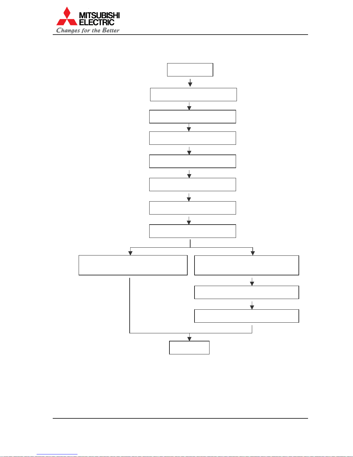
1.1. Flowchart
Start
1.5.3 System set up
Finish
1.5.2 Dipswitch setting
1.5.4 Color balance adjustment
1.8 Display memory setting
1.9 Setting as daisy chain connection
1.2 Set-up and installation
1.3 Connecting
1.6 Input memory setting (When the
main unit input port is selected)
1.4 Picture outline adjustment
1.7 Input memory setting (When the
input board is selected)
1.5.5 Image set up
REV 1.4
5
1.2. Installation
1.2.1. Safety precaution
• This product requires special installation to prevent falling or toppling. This should be done
by installation specialists.
• Be sure to read this manual and user’s manual for your safety before starting assembly or
installation.
• Be sure to use the supplied accessories for assembly or installation.
• Attach all the screws and fixtures specified in this manual securely.
• Reinforce the wall surface and floor so that it can support the total weights of the products
for a long time and resist earthquakes, possible vibrations, and external forces.
• Ensure that the safety factor is more than 10 (or ensure that the total bolts can bear ten
times the weight of the projectors and the brackets).
• Do not use the projector near a heater or in a humid, dusty or smoky location.
• Do not install the product with its intakes, exhaust slots and ventilation holes blocked. The
unit may overheat and cause a fire or breakdown.
• Be sure that lighting or sunlight does not leak into the screens.
• Inspect the mounting fixings more than once in a year as needed.
1.2.2. Preparation
Make sure that all of the following are supplied.
Supplied accessories (per unit) Q’ty Necessary tools
1. Hexagon socket head bolt (M6)
8
2. Flat washer (for M6)
8
3. Spring washer (for M6)
8
4. Joint hole seal
1
5. Power cord (1.8m)
for North America and Europe
(in VS-50XL20U and VS-67XL20U)
2
6. Control cable
1
7. User’s manual
1
1. Allen wrench 2mm/4mm/5mm
2. Phillips screwdriver #2
3. Level
4. Stepladder
5. Spacer
(1mm thickness
for VS-50XL20U and VS-50XLW20U,
2mm thickness for VS-67XL20U)
6. Wrench (for level adjuster)
Optional products Others
1. Wireless/wired remote control: R-FD10TX
2. Input board: VC‐B20KA
3. Input board: VC‐B20KV
4. Power cord (3m)
for North America: JC-PC3MA
for Europe: JC-PC3ME
for China: JC-PC3MC
1. Base stand
2. Level adjuster
3. Level adjuster fixing metal part
4. Wall fixing metal part
5. Anchor bolt
6. Hexagon socket head cap screw (M6)
VS-50XL20U, VS-67XL20U, VS-50XLW20U
Set-up and Installation Manual
6
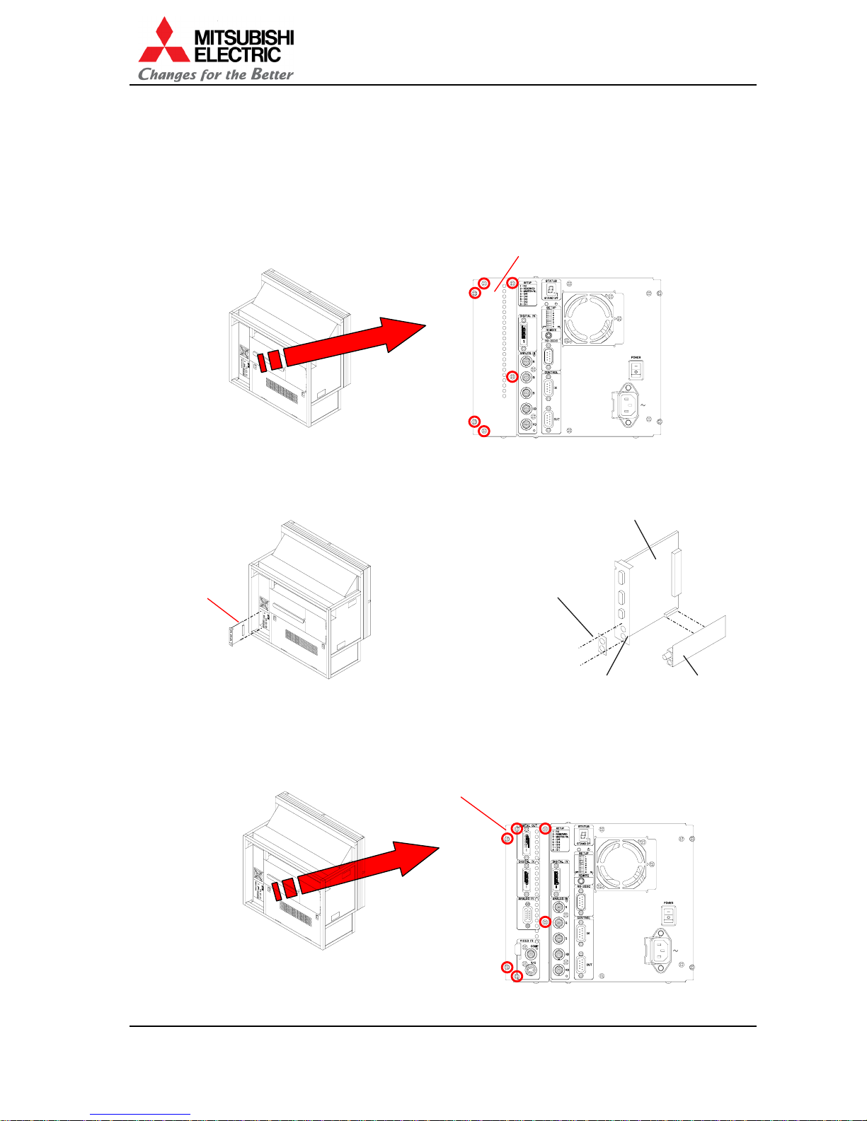
1.2.3. Input board installation (When using optional input board)
When using the optional input board, VC-B20KA, VC-B20KV, install it into the projector according
to the following steps.
Be sure to turn off the main power switch when you attach it.
1. Remove the panel cover in the control panel by removing the 6 screws at the positions
shown in the figure.
2. When you use VC-B20KV, stick the supplied terminal name label on VC-B20KA, and then
combine VC-B20KV and VC-B20KA with 2 supplied screws.
Firmly insert the input board through the guide rail to the end.
3. Firmly attach the input board with the 6 screws that has been removed in the step 1 at the
positions shown in the figure.
Panel cover
Input board
Input board
2. Stick the supplied
terminal name label,
and then combine
VC-B20KV and
VC-B20KA with 2
supplied screws.
Input board
(VC-B20KV)
Input board
(VC-B20KA)
1. Remove 2 hole-stoppers.
REV 1.4
7
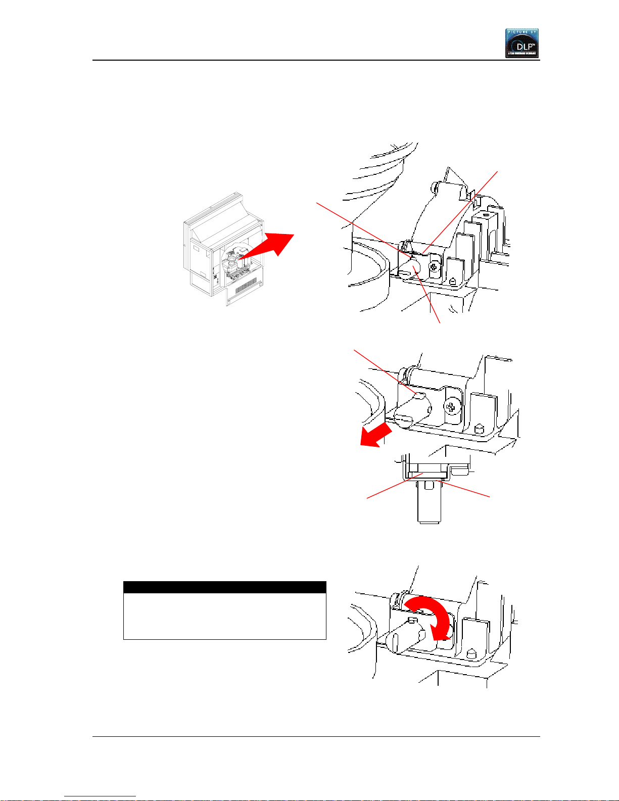
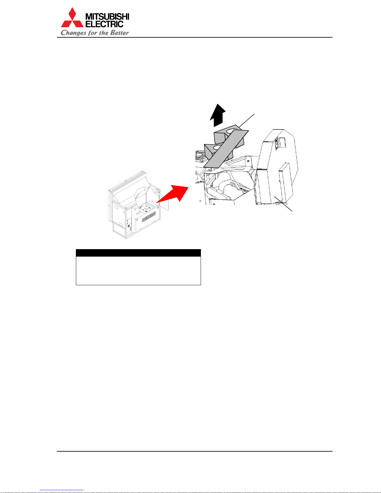
1.2.4. Color wheel unlocking
Unlock the color wheel surely before turning on the main power switch. Also for VS-50XLW20U,
detach the lamp cushion. Turning on without the unlocking or the detaching may cause damage.
1. Make sure the key slot faces
the top as you begin the
procedure.
2. Pull the color wheel cushion till
the flange hits the metal part.
• For VS-50XLW20U, pliers are
recommended to use since it is
hard to access with fingers.
3. Turn it 90 degrees clockwise.
Caution
Before shipment, be sure to lock the color
wheel (see chapter 1.13.2, on page 64).
Shipping the product without locking may
cause breakage.
Metal
Key slot
Color wheel cushion
Stopper
Flange
Metal
VS-50XL20U, VS-67XL20U, VS-50XLW20U
Set-up and Installation Manual
8
1.2.5. Lamp cushion detaching (for VS-50XLW20U)
For VS-50XLW20U, detach the lamp cushion before turning on the main power switch. Turning
on without detaching may cause smoking and catching fire.
• It should be remembered to lock the lamp cover after detaching. If you neglect to lock it, the
lamp changer may not work correctly.
Caution
Before shipment, be sure to insert the
cushion (see chapter 1.13.3, on page 65).
Shipping the product without inserting may
cause breakage.
Lamp cushion
Lamp cove
r
REV 1.4
9
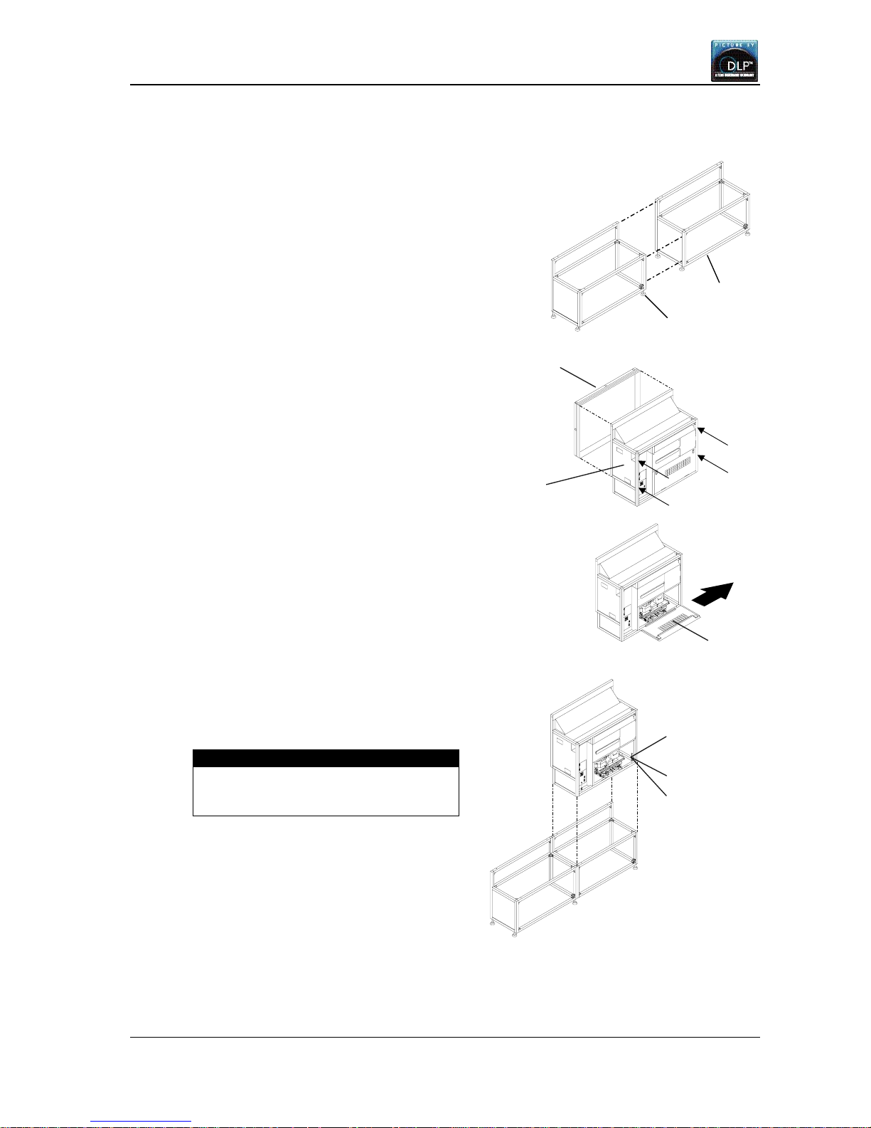
1.2.6. Installation procedure
1.2.6.1. Assembling the base stand and projector
1. Assemble base stands.
2. Adjust the level adjuster to make the base
stand both level and plumb by means of spirit
level.
3. Loosen the 4 screws per units shown by the
arrow lines in the right figure with the Allen
wrench (5 mm) to remove the screen units
from all projectors to be installed (this applies
to model VS-50XL20U and VS-50XLW20U
which are supplied with the screen fitted).
4. Open the lower door 90 degrees by pushing
down the handles. And then slide to the right
to detach. The door cannot be opened further
than 90 degrees.
5. Place the lower projector on the base stand.
6. Fix the projector at 4 points with supplied
hexagon socket head bolts, spring washers
and flat washers.
Caution
When holding up the projector, be
careful not to put your hand between the
projector and the base stand.
Lower door
Hexagon socket
head bolt
Base stand
Level adjuster
Screen unit
Cube unit
Flat washer
Spri ng washe r
VS-50XL20U, VS-67XL20U, VS-50XLW20U
Set-up and Installation Manual
10
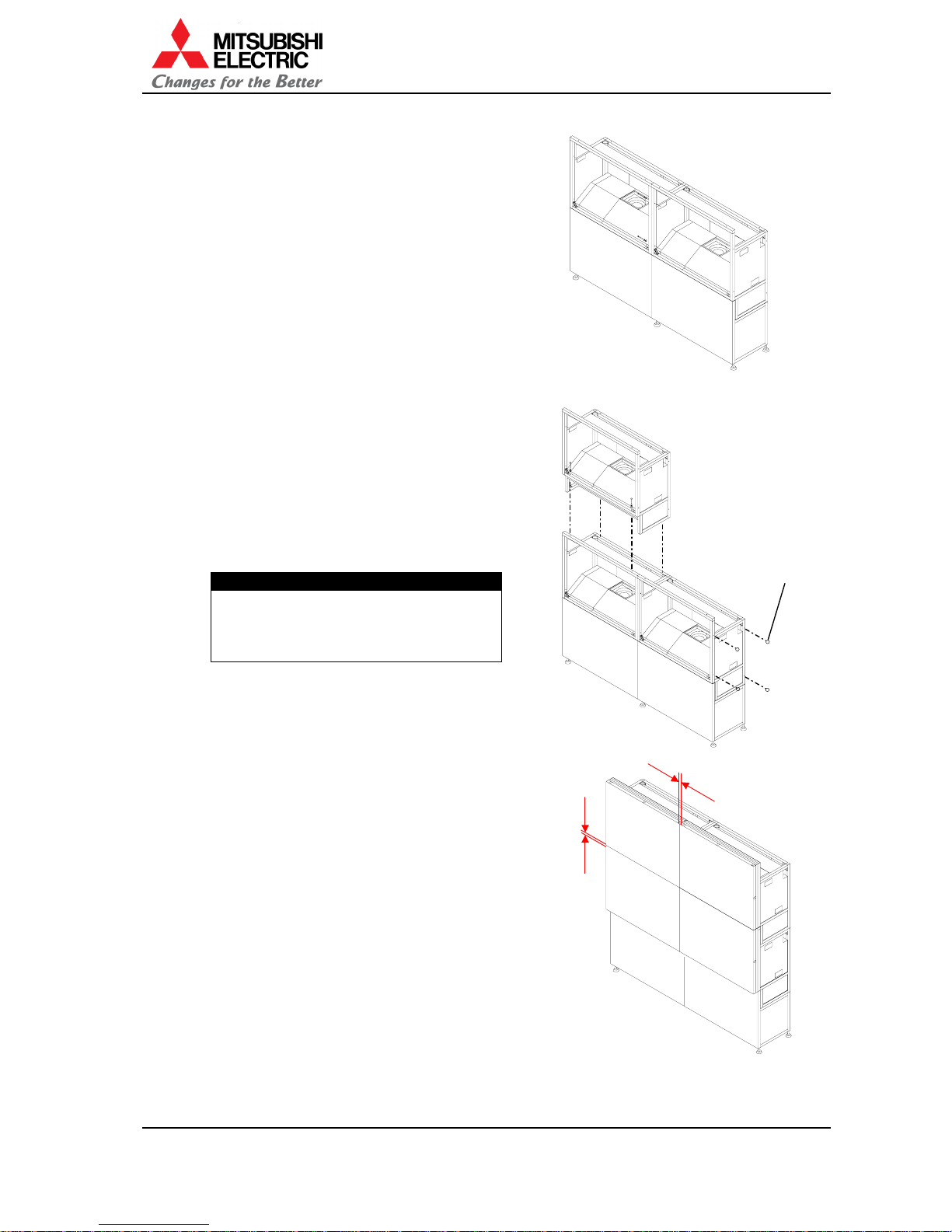
7. Place the next bottom row projector on the
base stand and fix it in the same way.
8. Join the right and left projectors at 4 points
with supplied hexagon socket head bolts,
spring washers and flat washers.
9. Place the upper projectors on the assembled
unit.
10. Fix them vertically and horizontally at 4 points
each with supplied hexagon socket head bolts,
spring washers and flat washers.
11. Stop up the holes in both sides that are not
used for multi-screen with joint hole seals.
Caution
To avoid the units from falling, measure
the horizontal and vertical degrees with
the level etc. and make sure the units
are stably assembled.
1.2.6.2. Space adjustment between the screens
1. Temporarily attach the screen units, which
were detached in the previous step (for
VS-67XL20U, the screens were supplied
separately).
2. Put the spacers between each screens and
adjust the screen gaps to be 1 mm for
VS-50XL20U/VS-50XLW20U or 2 mm for
VS-67XL20U.
3. Firmly tighten the 4 screen fixing screws.
1mm
(2mm)
1mm
(2mm)
Joint hole seal
REV 1.4
11
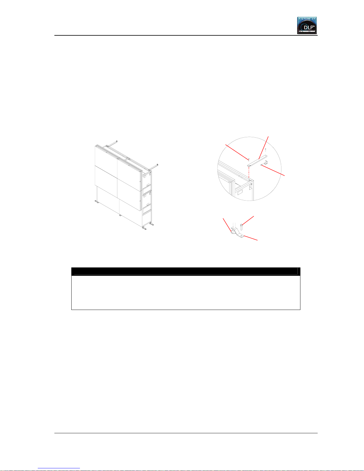
1.2.6.3. Fixing to the wall and floor
You don’t have to attach the lower door in this chapter since the picture outline has yet to be
adjusted as explained in the next chapter.
After the picture outline adjustment, attach the door in the reverse order of 1.2.6.1.
1. Attach floor fixing brackets to 4 corners of the level adjuster and fix them to the floor with the
anchor bolts.
2. Fix the back of the upper part of the projector to the wall with wall fixing brackets such as
shown in the following figure.
Caution
Make sure the whole set is assembled firmly and installed stably. To prevent the set
from falling due to unpredictable events such as earthquakes and shocks, fix the set
firmly to the wall and floor. Furthermore, carefully confirm the strength of the fixing area
of the installation place (wall and floor). The wall and floor fixing method differs
according to the number of the assembled units.
A
nchor bolt
A
djuster
A
nchor bolt
Wall fixing brackets
Floor fixing brackets
Hexagon socket head
cap screw (M6)
VS-50XL20U, VS-67XL20U, VS-50XLW20U
Set-up and Installation Manual
12
1.3. Connecting
1.3.1. Connecting with video device
Connect with image input sources adequately.
1.3.2. Control signal connection
An external controller such as a personal computer etc. can control the projector through
RS232C format communication. In the case of multi-screen, connect the external controller with
one projector via RS232C and connect CONTROL IN and CONTROL OUT terminals between
projectors with supplied control cables. Do not connect to a loop.
Each projector can be controlled separately from one controller by allocating ID numbers. Up to
32 projectors can be chained in one control line. Make sure that the dipswitch (chapter 1.5.2, on
page 21) is set adequately according to the connection.
1.3.3. Digital image signal connection
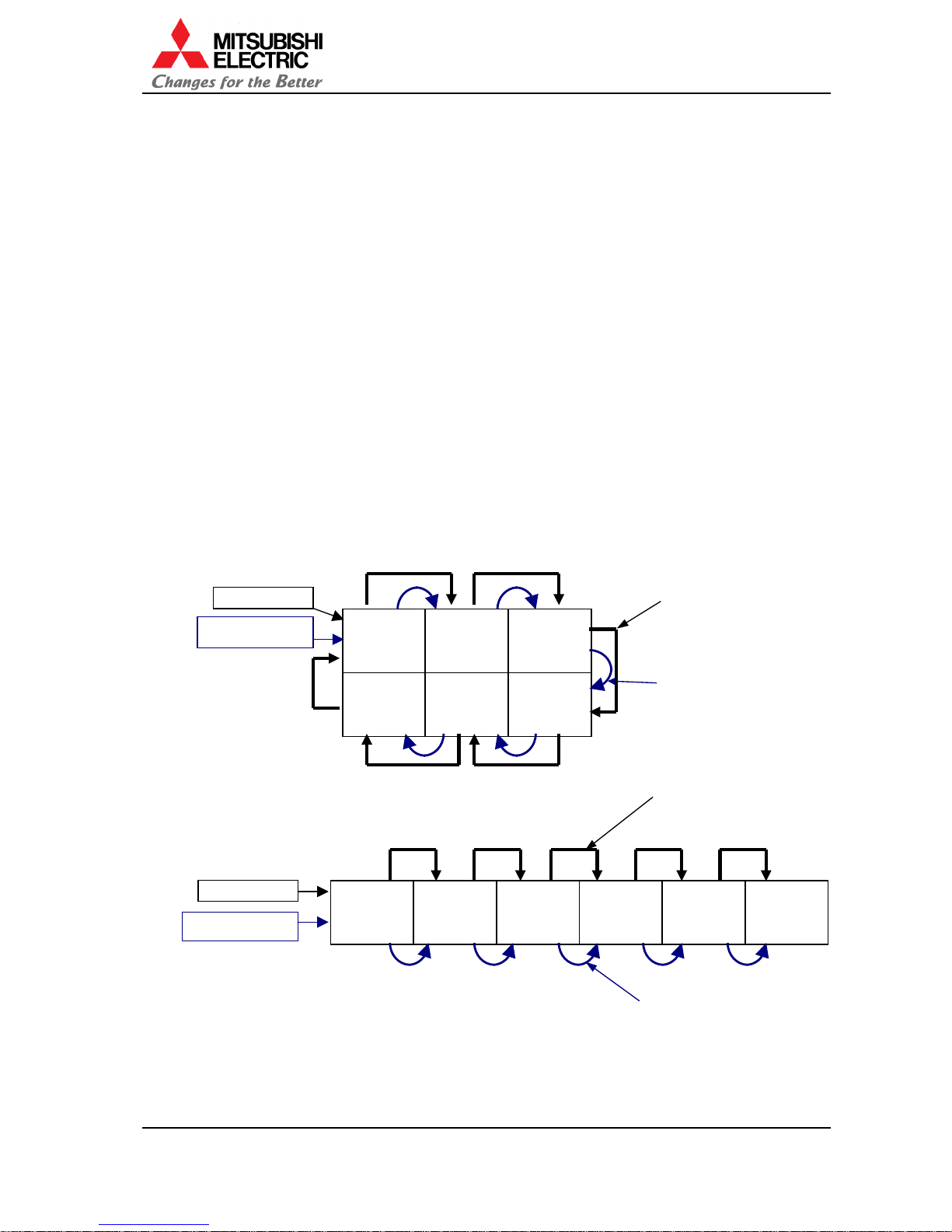
1.3.3.1. In the case of daisy chain
In the case of digital connection by daisy chain, connect DIGITAL IN and DIGITAL OUT terminals
between projectors with digital cables (DVI). The digital image signal can accept to daisy chain
up to 16.
In the case of 2 to 3
In the case of 1 to 6
(In this case, it cannot be connected to a loop.)
Panel 1 Panel 2 Panel 3
Panel 4 Panel 5 Panel 6
Panel 1 Panel 2 Panel 3 Panel 4 Panel 5 Panel 6
Video device
External controller
Supplied digital cables
(6 pcs)
Supplied control cables
(5 pcs)
Supplied digital cables
(5 pcs)
Supplied control cables
(5 pcs)
Video device
External controller
REV 1.4
13
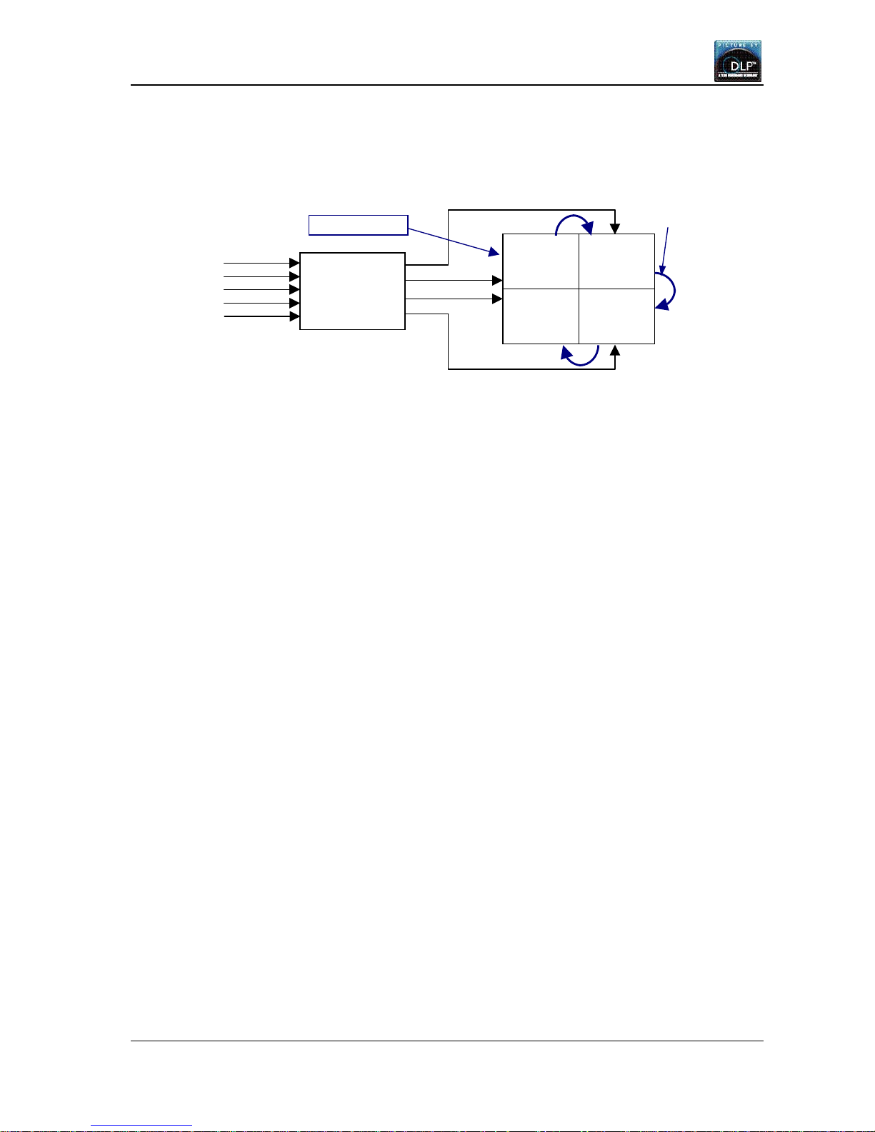
1.3.3.2. In the case of other than daisy chain
The multi-screen can be configured by connecting with matrix switch as well as daisy chain
connection.
Connecting with matrix switch
Panel 1 Panel 2
Panel 3 Panel 4
Matrix switch
Input 1
Input 2
Input 3
Input 4
Input 5
External
Supplied
VS-50XL20U, VS-67XL20U, VS-50XLW20U
Set-up and Installation Manual
14
1.4. Picture outline adjustment
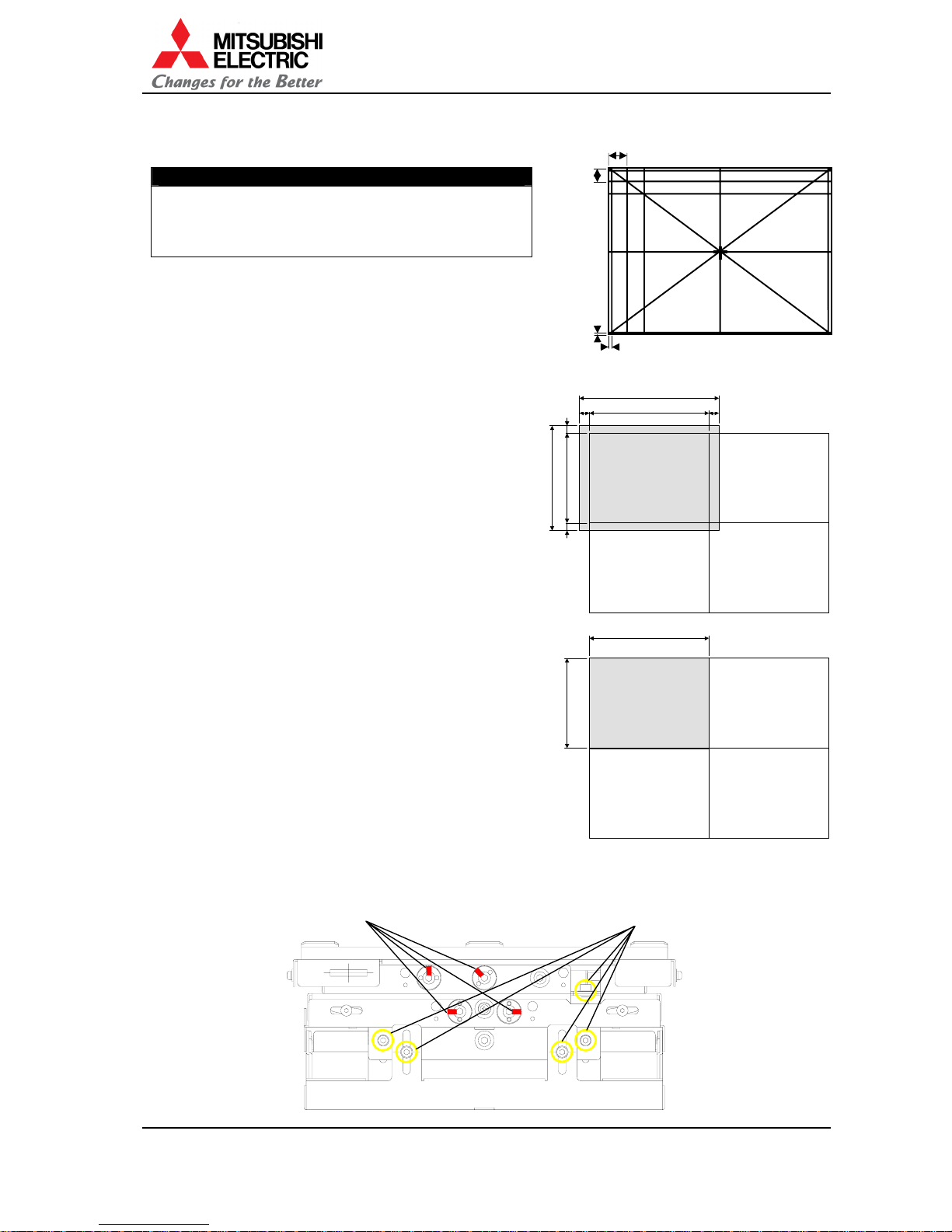
1.4.1. Displaying internal test pattern
Press [TEST] button twice to display the internal
crosshatch pattern for picture outline adjustment.
This pattern is a crosshatch with lines spaced at
16 pixels (horizontal) and 12 pixels (vertical).
There are also the adjustment lines for over scan
located 5th pixel inside from each side and 4th pixel
inside from top/bottom end.
1.4.2. Overscan mode
1.4.2.1. In the case of over scan
Adjust the picture outline so that 4 horizontal pixels
at each end and 3 vertical pixels at each end are
projected outside the screen edge.
With overlap setting (chapter 1.5.3.6, on page 22),
a black pixel-lacking area in fringe of the screen
becomes hard to see, even if the projection image
unexpectedly shifts in daisy-chained multi-screen.
The numbers of pixels per screen are;
Horizontal: 1,024-4-4=1,016 pixels
Vertical: 768-3-3=762 pixels
1.4.2.2. In the case of non-over scan
Adjust picture outline without projecting pixels
outside the screen.
The numbers of pixels per screen are;
Horizontal: 1,024 pixels
Vertical: 768 pixels
1.4.3. Release the lock screws
Before 6-axis adjustment, release the locks on the adjuster. Loosen the 4 locking screws by Allen
wrench (2mm) and 5 fixing screws in the adjuster by Allen wrench (4mm).
Caution
Before turning on, make sure again that the color
wheel has been unlocked (chapter 1.2.4, on page 7)
and, for VS-50XLW20U, the lamp cushion has been
detached (chapter 1.2.5, on page 8).
16 pixels
12 pixels
4
th
pixel
5th pixel
1024
768
1024
1008
8 8
756 6 6
768
1016
4 4
33762
5 fixing screws
4 lock screws
REV 1.4
15
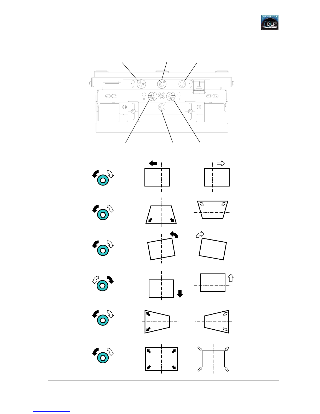
C: Tilt
D: V position
F: Zoom
View from the screen
1.4.4. 6-axis adjustment
E: H keystone
B: V keystone
A: H position
B: V keystone
E: H keystone
A: H position C: Tilt
F: Zoom D: V position
VS-50XL20U, VS-67XL20U, VS-50XLW20U
Set-up and Installation Manual
16
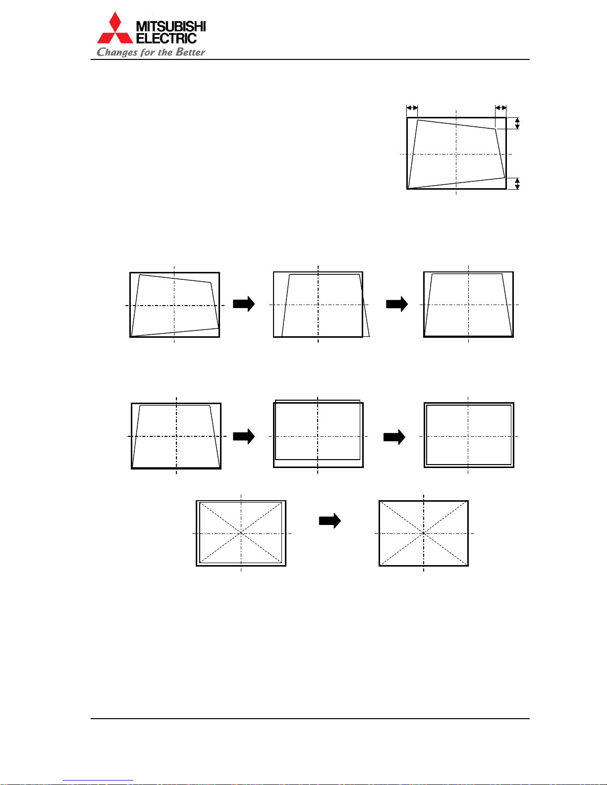
1.4.5. Adjusting procedure
Perform the picture outline adjustment by Allen wrench (5mm)
by referring to the previous chapter of “6-axis adjustment”.
1. After making the image size smaller than the outline of the
screen using the zoom axis, adjust Tilt, V position and H
position so that upper and lower spaces and right and left
spaces will be almost equalized respectively.
A=A', B=B'
2. After correcting the horizontal keystone distortion, adjust the image position to the center of
the screen with “H position”.
3. After correcting the vertical keystone distortion, adjust the image position to the center of the
screen with “V position”.
4. Adjust the image size to fit the outline of the screen.
5. After adjusting roughly on each single screen, adjust finely on the multi screen so that each
screen edge will link seamlessly.
1.4.6. Fixing the adjuster
Fix the 5 fixing screws in the reverse order of “1.4.3 Release the lock screws” on page 14.
Before shipment, in addition to above, be sure to fix the 4 lock screws of the adjuster and perform
the color wheel locking. Also for VS-50XLW20U, be sure to insert the lamp cushion (see chapter
1.13, on page 64).
A
A
'
B
B'
A
djust the horizontally
shifted image to the
center of the screen.
Correct the horizontal
keystone distortion.
Correct the vertical
keystone distortion.
A
djust the vertically
shifted image to the
center of the screen.
REV 1.4
17
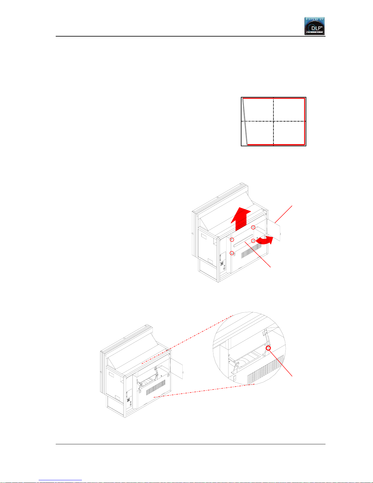
1.4.7. Mirror distortion adjustment (for VS-50XL20U and VS-50XLW20U)
1.4.7.1. Parallelogram distortion correction
If a parallelogram distortion that cannot be corrected by 6-axis adjuster appears, correct it
according to the following procedure.
1. Allign top, bottom and right lines of the crosshatch pattern
with the screen edge by 6-axis adjuster.
2. Loosen 4 screws in the rear panel.
Detach the panel with opening the upper door and lifting the panel.
3. Loosen the mirror fixing screw located in the right seeing from the rear side.
Upper
doo
r
Rear panel
Mirror fixing
screw
VS-50XL20U, VS-67XL20U, VS-50XLW20U
Set-up and Installation Manual
18
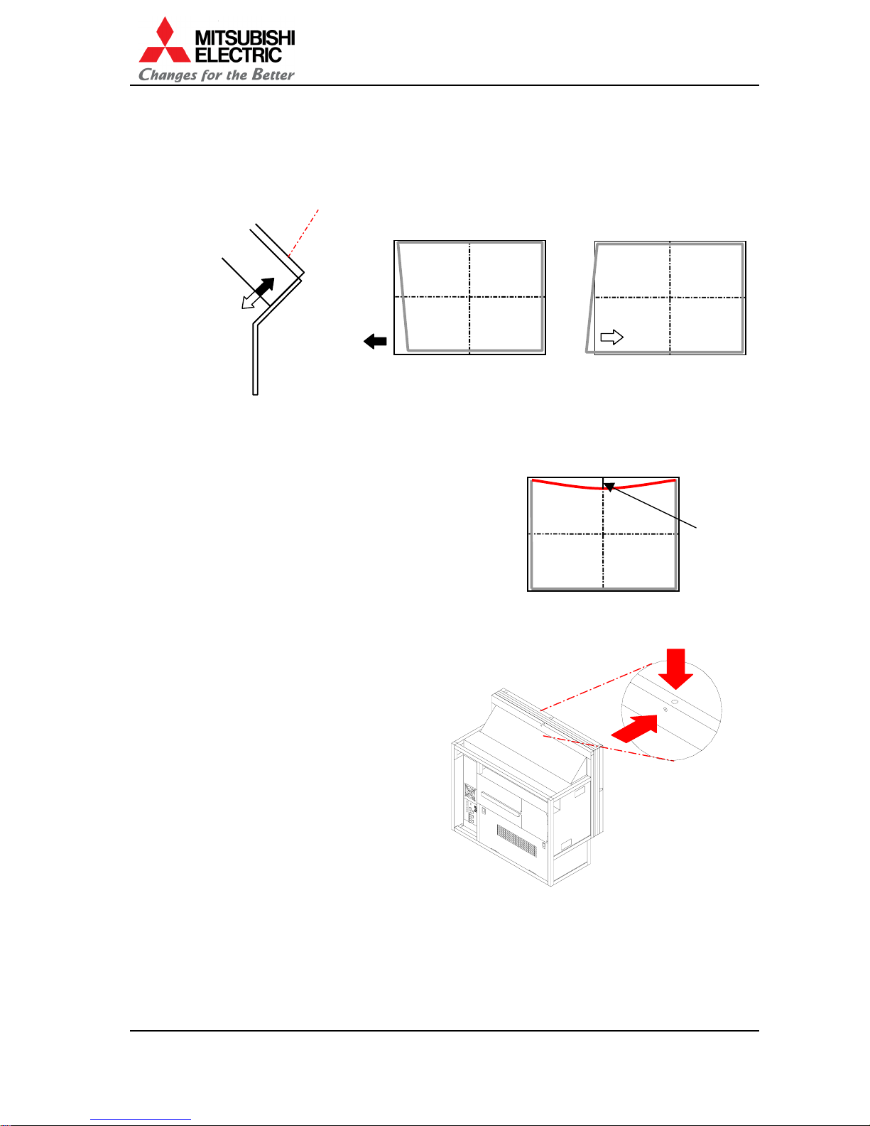
4. Correct the distortion by moving the lower part of the mirror up or down.
In the case that the lower left image is smaller: Move it upward
In the case that the lower left image is larger: Move it downward
5. Tighten the mirror fixing screw.
6. After the correcting, adjust finely by 6-axis adjuster.
1.4.7.2. Pincushion distortion correction
If pincushion distortion, which cannot be corrected by
6-axis adjuster, appears, correct it according to the
following procedure. This correction should be done
before cube stacking.
1. Allign upper left and upper right corners of the
crosshatch pattern with the screen corners by 6-axis
adjuster.
2. Loosen the fixing screw and then turn the
adjustment screw clockwise until the
distortion is corrected.
3. After the adjustment, tighten the fixing screw.
4. After the adjustment, fix the 6-axis adjuster (chapter 1.4.6, on page 16).
Mirror
In the case that the lower
left image is smaller.
In the case that the lower
left image is larger.
Pin cushion
1. Fixing screw
2. Adjustment screw
REV 1.4
19
1.5. Initial set up
1.5.1. Menu operation
1.5.1.1. Control button list
In normal mode In advanced mode
Menu OFF Menu OFF Menu ON
Remote
control
In stand-
by state
Test pattern
ON
Test pattern
OFF
Test pattern
ON
Test pattern
OFF
Test pattern
ON
Test pattern
OFF
POWER ON Turn on -
POWER OFF - Turn off
DISPLAY - Status information Status information (Press-and-hold for detail information)
PIC MUTE - - - Picture mute - Picture mute
INPUT A - - Selective input signal list
MENU1 - - Menu 1 -
MENU2 - -
Menu 2
(Press-and-hold for system
memory menu)
-
MEM LIST
- -
Input memory and display memory list
R
- -
R raster on/off R input on/off R raster on/off R input on/off
G - - G raster on/off G input on/off G raster on/off G input on/off
B - - B raster on/off B input on/off B raster on/off B input on/off
TEST - - Test pattern on – pattern rounding – test pattern off
FUNC - - Remote ID setting mode on/off
NORMAL - Normal mode/advanced mode switching Initialize
ESC - Cancel, back or test pattern off, etc.
ENTER
- -
Define
UP - - - - Menu option and cursor up
DOWN - - - - Menu option and cursor down
LEFT
- - - -
Value down
RIGHT
- - - -
Value up
Number
-
Display memory calling
-
1.5.1.2. Operation mode
• This product has two operation modes, “normal mode” and “advanced mode”. Use the
normal mode in the usual operation. Switch to the advanced mode when you set up or
adjust the projector.
• The two modes can be switched by [NORMAL] button when there is no menu on screen.
• The normal mode allows you to turn off the power by [POWER] button, to display the status
information by [DISPLAY] button, to change the operation mode by [NORMAL] button and to
call the display memory by number buttons.
• Adjustment menu cannot be called in the normal mode.
• In advanced mode, the status information described in
right figure appears on screen.
1. Status display:
• “!” mark appears when values in menu are
adjusted. It is also displayed when a value is
automatically changed by internal process.
• In VS-50XLW20U, “☀” mark appears when the
status of spare lamp is other than “NEW”.
! ANALOG NO SIGNAL ID 01
Status Input port Comment Set ID

VS-50XL20U, VS-67XL20U, VS-50XLW20U
Set-up and Installation Manual
20
LAMP TIMER 99999H
INPUT ANALOG
SYSTEM ID 01
LAMP A NEW BUSY
LAMP B USED STANDBY
NO SIGNAL
! ANALOG ID01
F/W VER P01.50A
H/W VER 12.19
SET TIMER 99999H
MASTER
L.SENSOR 125
• During lamp position auto calibration (for VS-50XLW20U) and initial sensor value
obtaining, the operating status is noticed by figures such as “3”, “4” or “7”. When
the function has worked correctly, it disappears after 5-minute displaying.
2. Input port: Displaying current input port.
3. Comment:
• “NO SIGNAL” is displayed when any image signal is not input.
• “TEST *” is displayed during internal test pattern displaying.
• “MUTE” is displayed during picture mute.
4.
Set ID: Displaying set ID.
1.5.1.3. Basic menu operation
• Adjustments should be conducted by means of the remote control in advanced mode.
• [MENU1] button displays menu 1.
• [MENU2] button displays menu 2 while the input board is attached. Press and hold the
[MENU2] button to display the system memory menu.
• If you select an item in the menu 1 or 2 and press [ENTER] button, you can adjust each item.
Some items indicate the lower menu layer.
• Up/down button selects menu item. Left/right button changes selected value.
• If you press [NORMAL] button in the adjusting item, the message “RESET OK?” appears
and it resets adjustment values after pressing [ENTER] button. By [ESC] button, you can exit
the menu without resetting.
• [FUNC] button allows remote ID setting. See chapter 1.5.1.4 for details.
• [TEST] button can select the test patterns. See chapter 2.3, on page 69 for details. Even if
any menus are being displayed on screen, the remote ID setting is available.
• [R][G][B] buttons can turn on/off the color mute. It is not available in a few test patterns.
• If 3-digit number is input by number buttons [1] to [0] while there is no menu on screen, the
display memory can be called directly. For instance, press 001 to call display memory 1.
• [DISPLAY] button shows status information.
1.5.1.4. Remote ID
Remote ID is used to operate the remote control toward specific screens in a multi-screen
system. Even if any menus are being displayed on screen, remote ID is selectable.
Remote ID can be designated the set ID, which is set in dipswitch, by 2-digit number in advanced
mode. For instance, if the set ID is one, input 01. It can be also selected by left/right button after
the [FUNC] button. The projector other than designated ID will ignore the remote control.
Pressing 00 after [FUNC] button enables remote control of all projectors regardless of the remote
ID setting.
Status information ([DISPLAY] button)
Detail status information
([DISPLAY] button press-and-hold)
Lamp status
Comment
(For
VS-50XLW20U)
Lamp operating time
Input port
Set ID
Firmware version
FPGA version
Set operating time
Master/slave setting
Luminous sensor value
REV 1.4
21
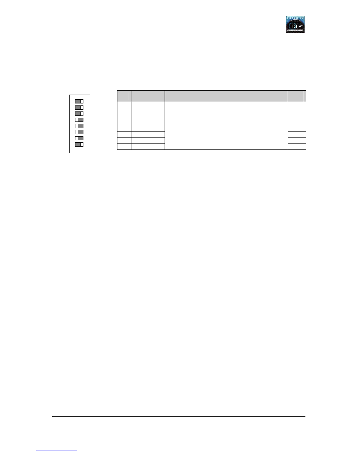
1.5.2. Dipswitch setting
Before turning on the main power switch, set the dipswitch correctly according to the system
configuration. Be sure to turn off the main power switch if you change the setting in the middle of
the operation. Only turning on the main power switch will renew the setting.
No. Name Function
Initial
setup
1 RC Enabling remote control (ON: enabled, OFF: disabled) ON
2 RESERVED Normally ON. When writing the firmware, set OFF. ON
3 MASTER MASTER/SLAVE setting (ON: MASTER, OFF: SLAVE) ON
4 ID5 OFF
5 ID4 OFF
6 ID3 OFF
7 ID2 OFF
8 ID1
Designating set ID number (1 to 32) (ON: 1, OFF: 0)
ID No.=1×(ID1)+2×(ID2)+4×(ID3)+8×(ID4)+16×(ID5)
Example:
ID No.=1: ID1=ON, ID2, ID3, ID4 and ID5=OFF
ID No.=32 :ID1, 2, 3, 4 and 5=OFF
ON
1.5.3. System set up
Set the “system memory” to suit the system as shown below. The parameters are effective for all
the input memories and display memories.
Press and hold [MENU2] button to display the system memory menu. You can exit the menu by
[ESC] button.
1.5.3.1. LAMP POWER
Used to set brightness mode.
You can select NORMAL or BRIGHT. Normally set NORMAL. BRIGHT mode can make high bright
display. In this case, the lamp life becomes shorter than NORMAL mode.
[Procedure]
1. Select LAMP POWER in MISC FUNCTION in the system menu.
2. Set NORMAL or BRIGHT.
1.5.3.2. LAMP MODE
Used to set lamp-driving system.
You can select LONG LIFE, NORMAL or F-REDUCTION. Normally set F-REDUCTION.
• F-REDUCTION: It drives with lamp flicker reduction.
• LONG LIFE: It drives with longer lamp life than F-REDUCTION mode even though the flickers
may occur.
• NORMAL: it automatically change F-REDUCTION and LONG LIFE mode.
[Procedure]
1. Select LAMP MODE in MISC FUNCTION in the system menu.
2. Set F-REDUCTION, LONG LIFE or NORMAL.
1.5.3.3. TERMINATE
Used to select the termination of analog input synchronizing signal in the main unit.
You can select 75 or 1K. Normally set 1K (1KΩ termination). If the synchronization is lost while
5-line (separate sync) signal inputs to the analog input terminal in the main unit, set this item to
75 (75Ω termination). The image may be displayed correctly.
[Procedure]
1. Select TERMINATE in MISC FUNCTION in the system menu.
2. Set 75 or 1K.
RESERVED
MASTER
ID5
ID4
ID3
RC
ID2
ID1
OFF ON
1
2
3
4
5
6
7
8
VS-50XL20U, VS-67XL20U, VS-50XLW20U
Set-up and Installation Manual
22
1.5.3.4. S.TERMINATE (When the input board is selected)
Used to select the termination of analog input synchronizing signal in the input board.
You can select 75 and 1K. Normally set 1K (1KΩ termination). If the synchronization is lost while
5-line (separate sync) signal inputs to the analog input terminal in the input board, set this item to
75 (75Ω termination). The image may be displayed correctly.
[Procedure]
1. Select S.TERMINATE in MISC FUNCTION in the system menu.
2. Set 75 or 1K.
1.5.3.5. START MEMORY
Used to designate the display memory number that is loaded at start-up. Normally set OFF. To
display a designated image source, set the registered display memory number (chapter 1.8.7, on
page 49), (or the registered input memory number when the main unit input port is selected). If it
is set OFF, the projector starts up with last loaded display memory.
[Procedure]
1. Select START MEMORY in MISC FUNCTION in the system menu.
2. Set 1 – 256 or OFF.
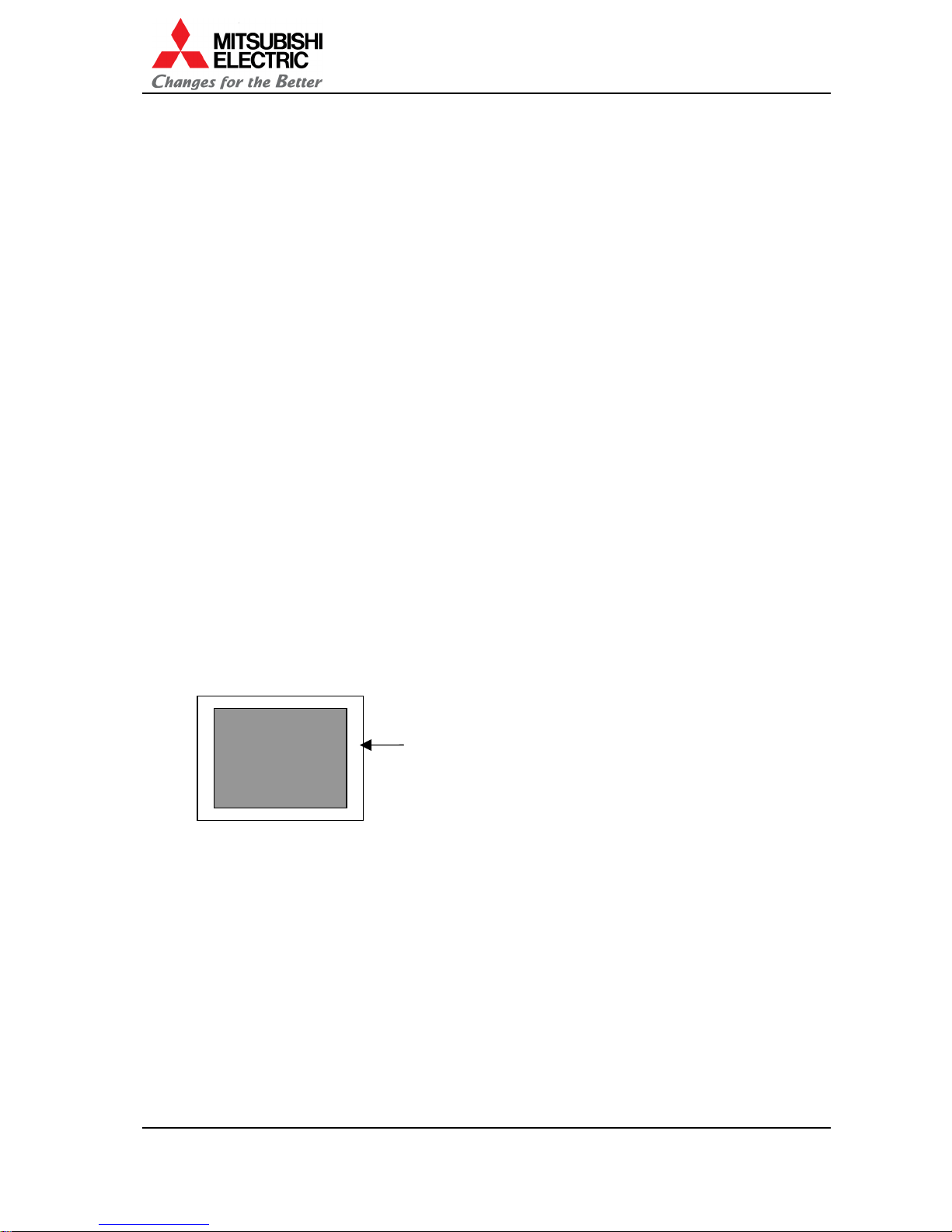
1.5.3.6. OVERLAP (When the input board is selected)
Used to set the overlap mode. In overlap mode, the projector can automatically calculate the
output size in consideration of overlapping area.
In the case of overlapping (chapter 1.4.2.1, on page 14), setting OVERLAP ON automatically
calculates the output size so as to fit the screen size and creates the overlap area that has a
width of 4 pixels each in the horizontal direction and a width of 3 pixels each in the vertical
direction.
In overlap mode, if the projection image unexpectedly shifts in daisy-chained multi-screen, a
black pixel-lacking area in fringe of the screen becomes hard to see.
In the case of a single screen or a multi-screen without the input board, normally set OFF since
blurred small characters may annoy you.
Also set OFF when the picture outline is adjusted without overlapping.
[Procedure]
1. Select OVERLAP in MISC FUNCTION in the system menu.
2. Set ON or OFF.
The screen has the overlap area with a horizontal width
of 4 pixels and a vertical width of 3 lines in overlap
mode.
Effective output
area

REV 1.4
23
1.5.3.7. OFFSET (When the input board is selected)
This adjustment is normally unnecessary.
Used to finely adjust the horizontal/vertical position and size if the picture outline is shifted after
the final 6-axis adjustment.
[Procedure]
1. Select OFFSET in MISC FUNCTION in the system menu.
2. H.POSITION: to adjust horizontal position.
3. V.POSITION: to adjust vertical position.
4. H.SIZE: to adjust horizontal size.
5. V.SIZE: to adjust vertical size.
1.5.3.8. BAUD RATE
Used to select the transmission speed of RS-232C in accordance with the external controller. You
can select 9,600bps or 19,200bps.
[Procedure]
1. Select BAUD RATE in MISC FUNCTION in the system menu.
2. Set 9600 or 19200.
1.5.3.9. SYSTEM SYNC
Used to set 60Hz or 50Hz in accordance with the vertical synchronizing signal of mainly
displayed moving pictures. Set 60Hz for NTSC signal or 50Hz for PAL signal. Make sure that all
projectors are set the same system sync setting in a multi-screen.
[Procedure]
1. Select SYSTEM SYNC in MISC FUNCTION in the system menu.
2. Set 60 or 50.
1.5.3.10. IMAGE FLIP
Used to invert the displayed image vertically or horizontally. Normally set S/W in cube projector.
• S/W: Normal image
• W/N: Vertically flip image
• S/E: Horizontally flip image
• N/E: Vertically/horizontally flip image
[Procedure]
1. Select IMAGE FLIP in MISC FUNCTION in the system menu.
2. Set S/W, W/N, S/E or N/E.
 Loading...