

Page 1

DLPTM Display Wall Cube /
LCD Display Wall
Seventy Series
Set-up Manual
REV. 1.3
January 29, 2010
Page 2
Table of Contents
1 OVERVIEW............................................................................................................................................................. 4
1.1 Product lineup................................................................................................................................................................................ 4
1.1.1 Main Products ............................................................................................................................................................................. 4
1.1.2 Optional products...................................................................................................................................................................... 5
1.2 Flowchart.......................................................................................................................................................................................... 6
1.3 Basic operation............................................................................................................................................................................... 8
1.3.1 Remote control unit................................................................................................................................................................... 8
1.3.2 Operation mode ......................................................................................................................................................................... 9
1.3.3 Menus.......................................................................................................................................................................................... 10
1.4 Control panel.................................................................................................................................................................................12
2 CUBE INSTALLATION (CUBE ).............................................................................................................................13
2.1 Safety precaution.........................................................................................................................................................................13
2.2 Preparation ....................................................................................................................................................................................14
2.2.1 Accessories.................................................................................................................................................................................14
2.2.2 Input boards installation........................................................................................................................................................ 14
2.2.3 Front attachment in 80” cabinet..........................................................................................................................................15
2.3 Engine embedding .....................................................................................................................................................................16
2.3.1 Rear ............................................................................................................................................................................................ 16
2.3.2 Front .......................................................................................................................................................................................... 17
2.4 Cube stacking ...............................................................................................................................................................................18
2.4.1 Screen demounting .................................................................................................................................................................18
2.4.2 Base stands and cubes assembling .....................................................................................................................................19
2.4.3 Screen mounting and open/close (Front ) ........................................................................................................................ 20
2.4.4 Screen gaps adjustment.........................................................................................................................................................21
2.4.5 Fixing to the wall and floor....................................................................................................................................................22
3 LCD PANEL INSTALLATION (LCD ).....................................................................................................................23
3.1 Safety precaution.........................................................................................................................................................................23
3.2 Preparation ....................................................................................................................................................................................24
3.2.1 Accessories.................................................................................................................................................................................24
3.2.2 Input boards installation........................................................................................................................................................ 24
3.3 Mounting........................................................................................................................................................................................24
3.3.1 For using commercial wall mount brackets ......................................................................................................................24
3.3.2 For using optional wall mount frame (BR-XM70KK)........................................................................................................ 26
3.3.3 Arrangement.............................................................................................................................................................................27
3.3.4 Wall mount frame attaching.................................................................................................................................................28
3.3.5 Preliminary internal cabling.................................................................................................................................................. 28
3.3.6 LCD panel mounting ...............................................................................................................................................................29
3.3.7 Panel open / close.....................................................................................................................................................................29
3.3.8 Panel gap adjustment............................................................................................................................................................. 30
3.3.9 IR receiver (R-XM70IR) attaching..........................................................................................................................................31
4 ADJUSTMENT......................................................................................................................................................32
4.1 Initial setting..................................................................................................................................................................................32
4.1.1 Connecting................................................................................................................................................................................. 32
4.1.2 Dipswitch setting...................................................................................................................................................................... 33
4.1.3 Power-on ....................................................................................................................................................................................33
4.1.4 Focus adjustment (Cube)...................................................................................................................................................... 33
4.1.5 Wallaby.......................................................................................................................................................................................34
4.2 System memory setting (basic)...............................................................................................................................................36
4.2.1 Basic adjustment items........................................................................................................................................................... 36
4.2.2 System memory saving........................................................................................................................................................... 37
4.3 Geometry adjustment ( Cube ) ................................................................................................................................................38
4.3.1 6-axis adjustment .................................................................................................................................................................... 38
4.3.2 Mirror correction.......................................................................................................................................................................41
4.4 Color balance adjustment.........................................................................................................................................................43
4.4.1 Preparation................................................................................................................................................................................ 43
4.4.2 SENSOR GAIN adjustment (LCD ) .........................................................................................................................................43
4.4.3 BLACK LEVEL adjustment .......................................................................................................................................................44
2 Seventy Series Set-up Manual
Page 3
CSC adjustment ........................................................................................................................................................................44
4.4.4
4.4.5 Light source output adjustment (LED, LCD).................................................................................................................... 45
4.4.6 WHITE BALANCE adjustment ................................................................................................................................................ 46
4.4.7 GRADATION adjustment.........................................................................................................................................................46
4.4.8 TAR GET COLOR ( Lamp ).......................................................................................................................................................... 46
4.4.9 SENSOR .......................................................................................................................................................................................47
4.5 System memory setting (custom)..........................................................................................................................................48
4.6 Input memory setting ................................................................................................................................................................54
4.6.1 Basic setting............................................................................................................................................................................... 54
4.6.2 Custom setting..........................................................................................................................................................................56
4.6.3 Input memory saving ..............................................................................................................................................................58
4.6.4 Input memory calling / deleting...........................................................................................................................................58
4.7 Display memory setting ............................................................................................................................................................59
4.7.1 Available layouts......................................................................................................................................................................59
4.7.2 Layout patterns setting........................................................................................................................................................... 60
4.7.3 Display memory saving ..........................................................................................................................................................63
4.7.4 Display memory calling / deleting .......................................................................................................................................63
5 MAINTENANCE ...................................................................................................................................................64
5.1 Lamp replacement (Lamp)......................................................................................................................................................64
5.1.1 Safety precaution ..................................................................................................................................................................... 64
5.1.2 Procedure ...................................................................................................................................................................................65
5.1.3 Auto-lamp changing function (Changer)........................................................................................................................ 66
5.2 Error indication.............................................................................................................................................................................67
5.2.1 On-screen indicator (Cube) .................................................................................................................................................. 67
5.2.2 Status indicator (Cube)..........................................................................................................................................................67
5.2.3 Side indicator (LCD )................................................................................................................................................................68
5.2.4 Internal temperature warning (LED)..................................................................................................................................68
5.3 Cleaning.......................................................................................................................................................................................... 69
5.4 Securing for delivery ( Cube )...................................................................................................................................................69
5.5 Resetting.........................................................................................................................................................................................69
5.6 About LCD panels (LCD )...........................................................................................................................................................70
6 SPECIFICATIONS .................................................................................................................................................71
6.1 Available input signals ...............................................................................................................................................................71
6.2 Menu trees .....................................................................................................................................................................................72
6.2.1 On-screen menus ..................................................................................................................................................................... 72
6.2.2 Wallaby menu...........................................................................................................................................................................75
6.3 Connectors / switches spec......................................................................................................................................................81
7 REVISION HISTORY.............................................................................................................................................82
* The symbol Changer , Front, etc. refers to lamp changer, front access models etc.
REV 1.3 3
Page 4

Product lineup
1
1
OOvveerrvviieeww
1
11..1
PPrroodduucctt lliinneeuupp
1.1.1 Main Products
Cubes Cube
A variety of cubes can be configured by combining engine units, cabinets, screen units and optional products.
With lamps Lamp
Size Access Resolution Lamp Combined name Engine unit Cabinet Screen unit
VS-50PH70U VS-PH70U
VS-50XH70U VS-XH70U
VS-50XL70U VS-XL70U
VS-50PHF70U VS-PH70U
VS-50XHF70U VS-XH70U
VS-50XLF70U VS-XL70U
VS-60PH70U VS-PH70U
VS-60XH70U VS-XH70U
VS-60XL70U VS-XL70U
VS-60PHF70U VS-PH70U
VS-60XHF70U VS-XH70U
VS-60XLF70U VS-XL70U
VS-67PH70U VS-PH70U
VS-67XH70U VS-XH70U
VS-67XL70U VS-XL70U
VS-67PHF70U VS-PH70U
VS-67XHF70U VS-XH70U
VS-67XLF70U VS-XL70U
VS-80PH75U VS-PH75U
VS-80PH70U VS-PH70U
S-5070CA SC-5070U
S-5070CAF SC-5070UF
S-6070CA SC-6070U
S-6070CAF SC-6070UF
S-6770CA SC-6770U
S-6770CAF SC-6770UF
S-8070CA SC-8070B
50”
60”
67”
80”
SXGA+
Rear
Front
Rear
Front
Rear
Front
Rear SXGA+
XGA
SXGA+
XGA
SXGA+
XGA
SXGA+
XGA
SXGA+
XGA
SXGA+
XGA
Changer
Single
Changer
Single
Changer
Single
Changer
Single
Changer
Single
Changer
Single
PH75
high brightness changer
Changer
• The product names marked in red may be delivered with the projection engine and for 50” also the screen,
already installed. 67” and 80” models always have the screen shipped separately.
4 Seventy Series Set-up Manual
Page 5
With LED light source LED
Size Access Resolution Combined name Engine unit Cabinet Screen unit
VS-50PE70U VS-PE70U
VS-50XE70U VS-XE70U
VS-50PEF70U VS-PE70U
VS-50XEF70U VS-XE70U
VS-60PE70U VS-PE70U
VS-60XE70U VS-XE70U
VS-60PEF70U VS-PE70U
VS-60XEF70U VS-XE70U
VS-67PE70U VS-PE70U
VS-67XE70U VS-XE70U
VS-67PEF70U VS-PE70U
VS-67XEF70U VS-XE70U
S-5070CAF SC-5070UF
S-6070CAF SC-6070UF
S-6770CAF SC-6770UF
S-5070CA SC-5070U
S-6070CA SC-6070U
S-6770CA SC-6770U
50”
60”
67”
Rear
Front
Rear
Front
Rear
Front
SXGA+
XGA
SXGA+
XGA
SXGA+
XGA
SXGA+
XGA
SXGA+
XGA
SXGA+
XGA
LCD panel LCD
VS-L46XM70U
1.1.2 Optional products
The main products are not equipped with any input ports. Arrange optional input boards according to input signals
to be displayed.
Optional products Product names Applicable main products
Input boards VC-B70D2 (for digital inputs)
Wireless / wired
remote control unit
Motorized adjustment tool
*
Motor units
for screen / mirror *
Power cord (3m) JC-PC3MA (for North America)
Spare lamps S-70LA (standard)
Spare color wheels S-703CW (3 segments)
Spare LED light source
module
Wall mount frame BR-XM70KK
IR receiver R-XM70IR
The combination of S-A70E and S-MA70E can be applied to the wall mount frame, which can adjust the gaps
between panels electrically.
VC-B70V2 (for video inputs)
VC-B70G2 (for analog inputs)
VC-B70DC (for daisy chain)
VC-B70SD1 (for SDI/HD-SDI input)
R-XL50TX
S-A70E
S-MA70E
JC-PC3ME (for Europe)
JC-PC3MC (for China)
S-75LA (for PH75)
S-704CW (4 segments)
S-70LE
Common
Common
For Lamp
For LED
For LCD
Product lineup
REV 1.3
5
Page 6
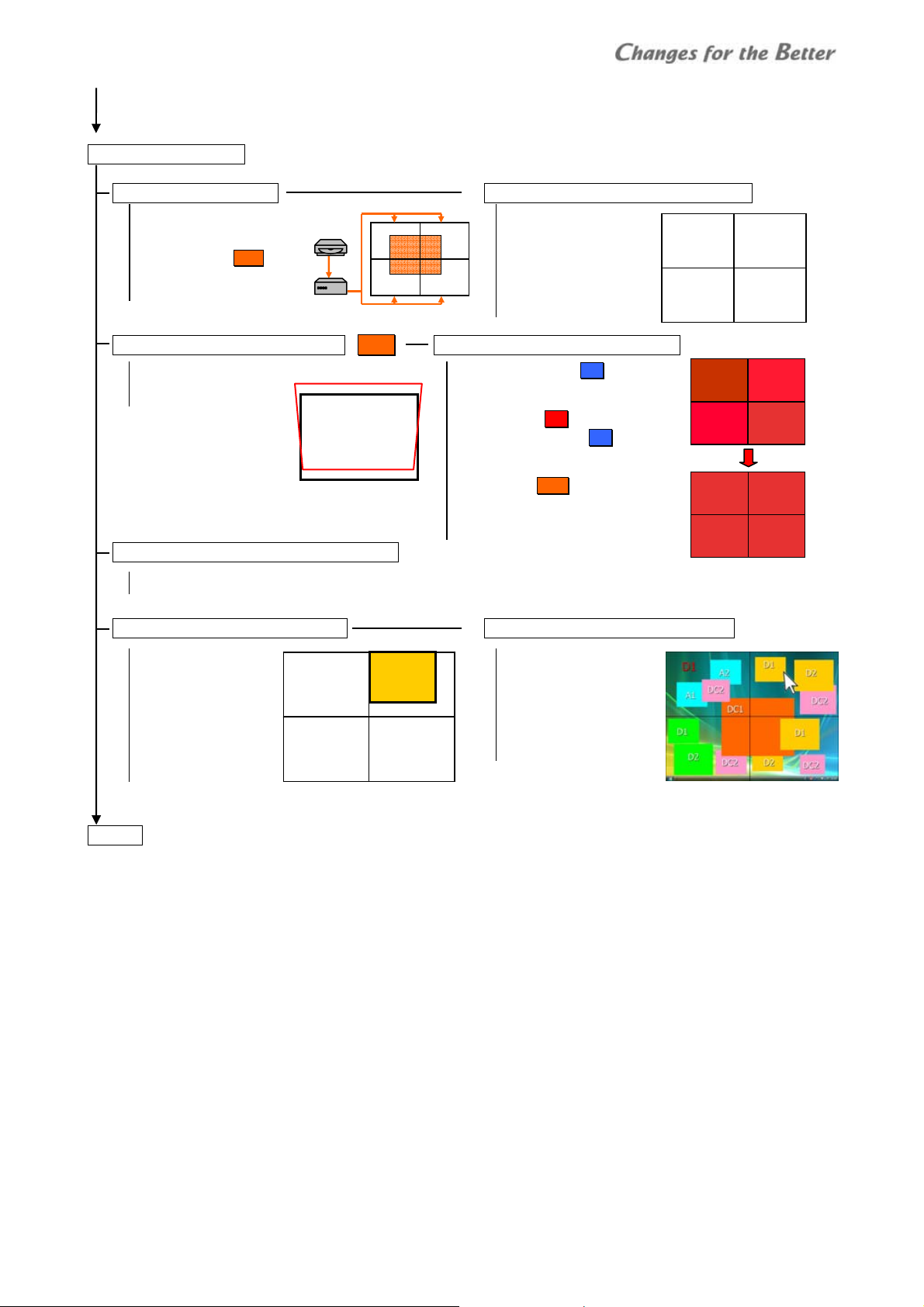
Flowchart
2
11..2
FFlloowwcchhaarrtt
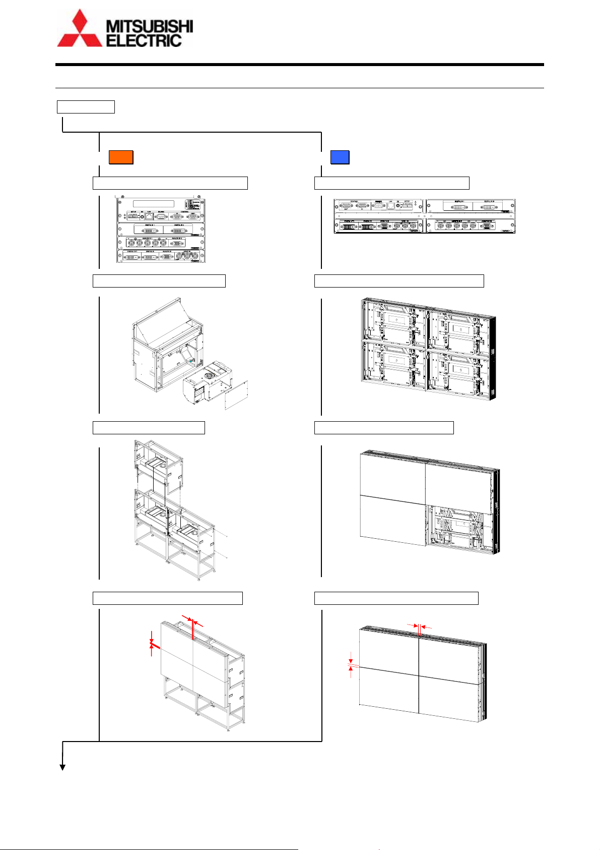
Installation
For Cube (page 13) For LCD (page 23)
Input boards installation (page
Engine embedding (page
Cube stacking (page
( Go to next page)
Screen gap adjustment (page
14) Input boards installation (page 24)
16) Wall mount frame attaching (page 26)
18) LCD panel mounting (page 29)
21) LCD panel gap adjustment (page 30)
6 Seventy Series Set-up Manual
Page 7
Adjustment (page
32)
Initial setting (page
Connecting
Dipswitch setting
Power-on
Focus adjustment Cube
32) Basic system memory setting (page 36)
A1
Unit ID assignment
IP address assignment
H. / V. LOCATION
(IMAGE FLIP)
(SYSTEM SYNC)
Geometory adjustment (page 38) (Cube) Color balance adjustment (page 43)
6-axis adjustment
Mirror correction
Sensor gain adjustment LC D
(BLACK LEVEL)
CSC
LED POWER gain LED
BACKLIGHT DIMMER gain LCD
(WHITE BALANCE)
GRADATION
TAR GET COLO R Lamp
SENSOR
Custom system memory setting (page
LAMP POWER / FRAME LOCK / REDUNDANCY / AMP. GAIN etc.
48)
Input signal adjustment (page
Input port selection
MEMORY SCAN
H. / V. POSITION
CLOCK PHASE
AMP. GAIN
etc.
54) layout pattern adjustment (page 59)
H=1, V=1
H=1, V=2
H=2, V=1
H=2, V=2
Input signal allocation
Position / size setting
Crop / zoom setting
Priority order setting
etc.
Finish
Flowchart
ID 1
MASTER
H=1, V=1
ID 3
SLAVE
H=1, V=2
ID 1
ID 3
ID 2
SLAVE
H=2, V=1
ID 4
SLAVE
H=2, V=2
ID 2
ID 4
REV 1.3 7
Page 8

Basic operation
3
11..3
BBaassiicc ooppeerraattiioonn
The cubes can be operated with the remote control unit or control software, “Wallaby” (page 34).
1.3.1 Remote control unit
In Cube , face the remote control toward the screen on each cube to control. Or facing to the MASTER cube (page
33) directs other cubes. In LCD , face to the IR receptor on the left side of the panel or to the optional IR receiver
(page 31).
It can control the imaging monitors (cubes or LCD panels) also through the cable supplied with the remote control.
Buttons
POWER Switch between power-on and standby state
DISPLAY *1
MUTE *1 -
INPUT A -
INPUT B
VIDEO -
MEM LIST - MEMORY CALL menu -
TEST - Internal test patterns *4
MENU1 - TOP menu Simple menu display
MENU2 -
ESC
ENTER - Enter
Up/down
arrows
Left/right
arrows
R, G, B - Primary color mute/display *5
numbers
NORMAL Switch between normal and advanced mode Value reset
FUNC - Remote ID switch *6
Slide switch - Switch the function between [DISPLAY] and [MUTE]
In normal
mode
Status
information
Switch the contents on the status indicator
Status
information
off
On-screen indicator off (available in light source off) Cube
Recall display memory by number
Status information (press-and-hold for advanced information)
Screen mute
Status bar off (on test patterns)
INPUT SELECT menu WINDOW PRIORITY menu (press-and-hold)
Light path calibration with [INPUT A] + [ESC] +[2-digit unit ID] Lamp
- INPUT MEMORY menu Manual lamp change with [INPUT B] + [ESC] +[2-digit unit ID] (Changer ) *2
SENSOR DATA window with [VIDEO] + [DISPLAY] LCD
SENSOR GAIN: AUTO ADJ. window with [VIDEO] + [ESC] LCD
DISPLAY MEMORY menu
SYSTEM MEMORY menu (press-and-hold)
Cancel, exit
- -
- -
- Remote ID input after [FUNC]
*1. The slide switch switches the function between [DISPLAY] and [MUTE].
*2. It is available even in standby state and blowout mode (page
*3. Specified window image will be muted off/on during DISPLAY > WINDOW 1 – 6 menu display.
*4. Every press of the button switches the test patterns to be displayed.
*5. Regardless of ID setting, the R / G / B button mutes (switches off) the red / green / blue color for the monitors.
When muted / un-muted monitors are mixed in a display wall, pressing R / G / B may just alternate the effect. To
un-mute all of the monitors, press and hold the R / G / B button.
*6. Number keys specify the ID number, or left/right buttons change the number by 1 and up/down buttons by 10.
In advanced mode
In menu off In menu on
*2
Cube
Screen mute
(Window mute)
-
Menu select,
cursor up/down
Option select,
value change
49).
*3
8 Seventy Series Set-up Manual
Page 9

1.3.2 Operation mode
For remote control, the monitors have 2 operation modes: “normal mode” and “advanced mode”. The normal mode is
for usual operation and advanced mode for set-up and adjustment. [NORMAL] button switches the modes when
there is no adjustment menu on screen. This status bar is shown on screen in the advanced mode.
Normal mode
Following operations are available in normal mode.
Button Func tion
[POWER] Switch between power-on and standby state
[DISPLAY] Status information, switch the contents on the status indicator
[ESC] Status information off
[NORMAL] Switch between normal and advanced mode
Numbers Recall a display memory (page 63) by 3-digit number. Press 001 for display memory 1.
Advanced mode
Monitor adjustments such as color balance and input signal adjustments should be done in advanced mode.
Status bar
No. Description No. Description
1 Selected display memory number (page 59)
Input memory number (page
2
foreground window
Foreground window number
3
4 Slot number and input port on foreground window 8
5
Remote ID
An individual monitor can be controlled remotely. Specify it with [FUNC] button followed by 2-digit unit ID number.
Specifying 00 means that all monitors will be controlled. To control only ID 1 monitor, press [FUNC] + [0] + [1].
• Arrow keys after [FUNC] can also specify the ID. Left/right buttons change the ID by 1 and up/down buttons by 10.
• Remote ID switch is available even when the menus are on displayed on the screen.
Test patterns
[TEST] button shows internal test patterns. Every press cycles through the patterns in the following order.
Full-bit white -> Crosshatch -> Adjustment white -> Gradation -> Color bar -> Test pattern off -> (Full-bit white)
icon is shown when the window is displayed in space
coordinates on another monitor.
Image status
• Test pattern name: in internal test pattern displaying
• SCREEN MUTE: in screen mute
• WINDOW MUTE: One of the windows is mute.
• NO SIGNAL: no signal on the foreground window
Press [ENTER] button to confirm.
1 2
3 4
5 6 7 8 9
54) and its comment on the
Redundancy (page
• : BOARD REDUNDANCY mode
• : PORT REDUNDANCY mode (The number shows the slot
6
7 Unit ID number
9
number)
• : COLOR-KEY mode
These indicators are shown when the function is set ON. The color of
indicator or changes to yellow when the signal is switched.
Remote ID indicator
* It is shown when remote controlling is available by remote ID setting.
Monitor status
: In waiting time for lamp calibration (page 52) or for initial sensor
•
data obtaining (page 47) ( Lamp).
The operation will be completed in 5 minutes and then the
indication will disappear.
• : The spare lamp status is not “NEW” (Changer).
• : Adjustment values have been changed.
* It appears when a value is changed automatically by internal
process as well as changed by remote control.
51) and color-key (page 50) setting, status
Basic operation
REV 1.3 9
Page 10
Basic operation
1.3.3 Menus
Basic menu operations
• The up/down arrow buttons on the remote control
move the yellow cursor to select menus.
• The left/right arrow buttons change the value in a
menu with left/right triangle marks.
• In a menu with “>” mark on the right, [ENTER] button
shows its lower layer menu. [ESC] button restores the
original upper menu.
• In a menu with an enter mark on the right, [ENTER]
button confirms or executes the menu.
• When values are changed in a menu,
appears. Save the change according to the necessity.
- In WINDOW PRIORITY menu, the mark appears
when an input memory in any of the windows is
changed.
- In INPUT MEMORY menu, the mark appears when
an input memory in the top window is changed.
• In the menu displaying, [MENU1] button changes the
menu GUI to the simple one. The image area behind
the menu can be observed widely. Re-pressing the
same button restores the original menu.
• Menus are not displayed when the monitors are
controlled by Wallaby.
mark
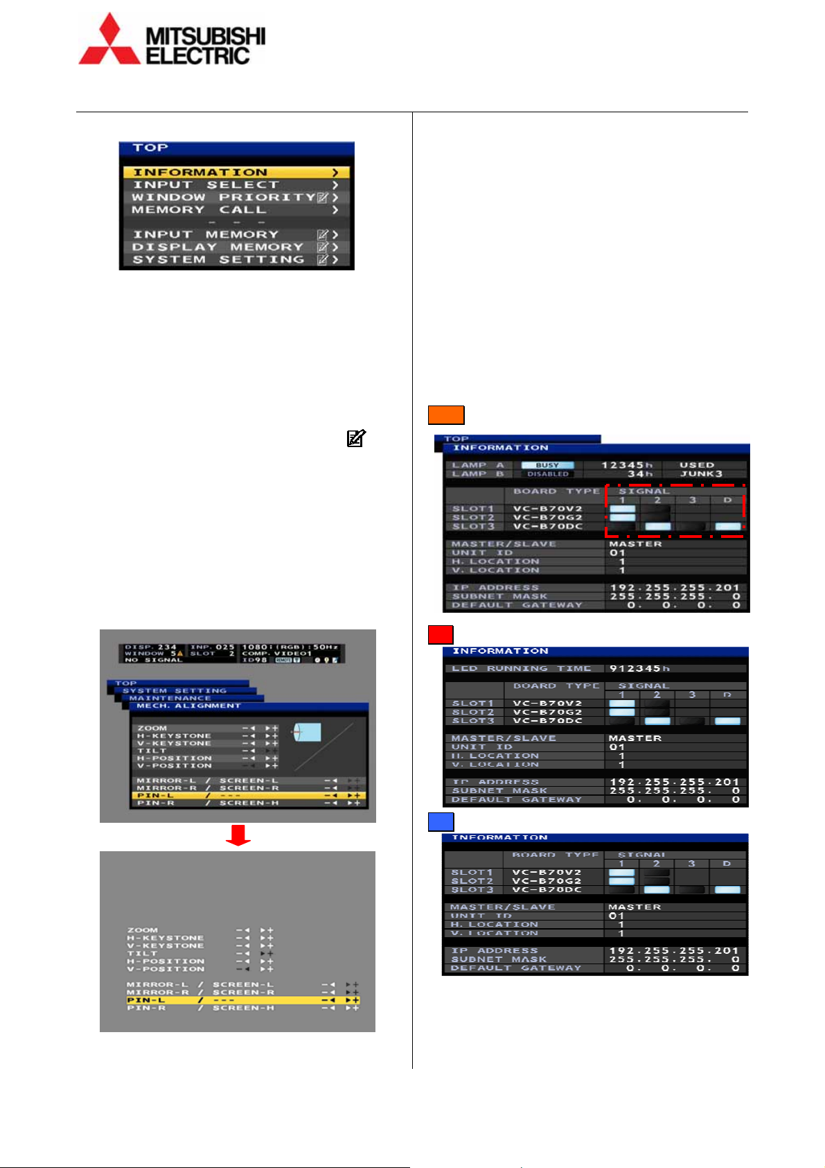
TOP menu
The TOP menu is displayed by [MENU1] button on the
remote control in the advanced mode. Starting from
the menu, which is the top of the menu tree, lower
menus can be choosen.
• Allocated short-cut buttons directly access each
menu not-through the TOP menu.
INFORMATION menu
It shows various status information on screen.
Short-cut: [DISPLAY] button
1 and 2 in SIGNAL column represent with or without
signals on each input port (The signal from the SDI
input board is shown only in 1). In the case of the daisy
chain board, it shows following signals.
1: digital in, 2: analog in, 3: video in, D: digital out
Lamp
LED
LCD
10 Seventy Series Set-up Manual
Page 11
T
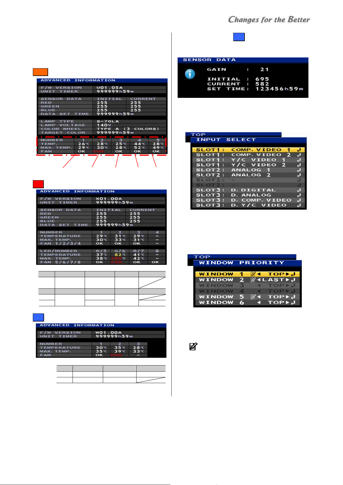
ADVANCED INFORMATION menu
Pressing-and-holding [DISPLAY] button on the status
information displays the advanced information. The
NUMBER section shows temperetures and fan status in
the following positions.
Lamp
Power PCB 1 Power PCB 2 DLP
M
chip Lamp A Lamp B
LED
No. 1 2 3 4
Tem p.
Power PCB 1 Power PCB 2
/ fan
No. 5 6 7 8
Temp. Green LED
Red LED
Fan
Green LED 1
DLPTM
chip
Blue LED
Green LED 2
LCD
No. 1 2 3
Temp. Power PCB 1 Power PCB 2 Sensor PCB
Fan Fan 2 (left) * Fan 2 (ri ght) *
* Seen from the panel front
SENSOR DATA menu LC D
Pressing [VIDEO] + [DISPLAY] button in the advanced
mode shows the light sensor data.
INPUT SELECT menu
It can select input ports to be adjusted (page 54).
Selected input signal will be displayed on top.
Short-cut: [INPUT A] button
WINDOW PRIORITY menu
It can set the window overlay priority order. The
designated window will be displayed on top or last
behind other windows.
Short-cut: Press-and-hold [INPUT A] button
It shows the priority order list and can set the order all
together, unlike PRIORITY menu (page
memory which should enter in each window menu to
set. To save the order, enter DISPLAY MEMORY menu
and save in a display memory (page
The
mark appears when an input memory in the
window is changed. To save the change, move the
window priority to the top and save the input memory.
62) in display
63).
Basic operation
REV 1.3 11
Page 12
Control panel
MEMORY CALL menu
Registered input memories / display memories can be
called (page
58, 63).
Short-cut: [MEM LIST] button
INPUT MEMORY menu
It can set input signals. See on page 54 for detail. The
setting can be memorized in 128 input memories.
Short-cut: [INPUT B] button
DISPLAY MEMORY menu
It can set display layout patterns. See on page 59 for
detail. The setting can be memorized in 256 display
memories.
Short-cut: [MENU2] button
SYSTEM SETTING menu
It can set an entire monitor / screen condition. See on
36 and 48 for detail. One condition is memorized
page
in the monitor.
Short-cut: Press-and-hold [MENU2] button.
4
11..4
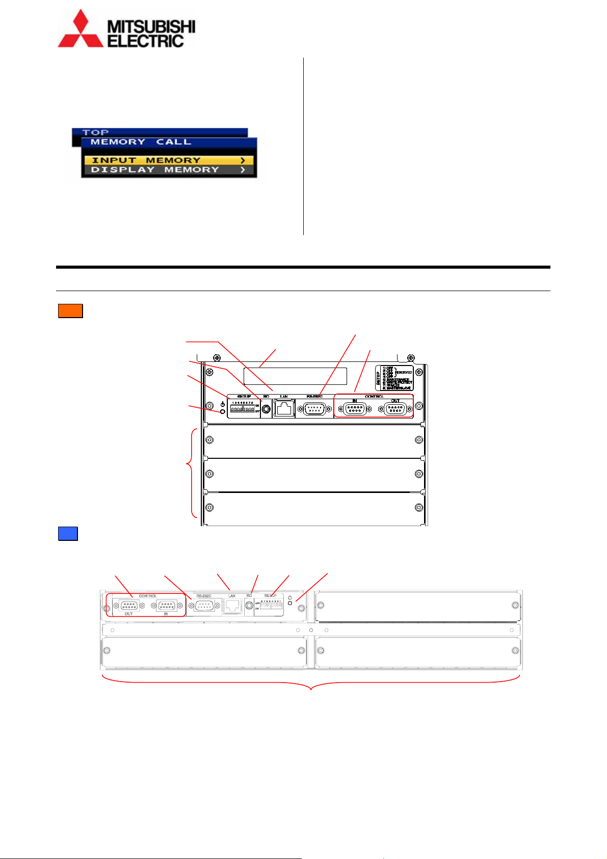
CCoonnttrrooll ppaanneell
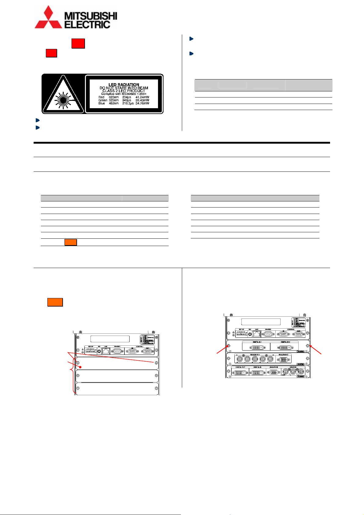
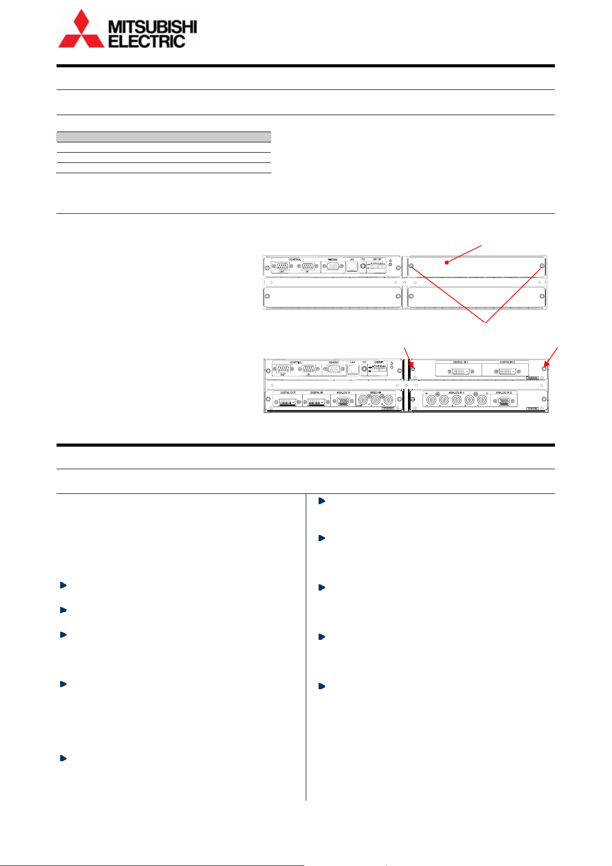
The control panel has the following functions.
Cube
Wired remote port (page 8)
Network port
(page 32)
Dipswitches
(page 32)
Standby switch
(page 33)
Status indicator”
(page 66)
RS-232 port (page 32)
Control ports (page 32)
Slot 1
Input board slots
(page 15)
Slot 2
Slot 3
LCD
Control
ports
(page 32)
RS-232
port
(page 32)
Network
port
(page 32)
Wired remote
port
(page 8)
Dipswitches
(page 32)
Standby
switch
(page 33)
Slot 1
Slot 2Slot 3
12 Seventy Series Set-up Manual
Input board slots (page 24)
Page 13
2
2
CCuubbee iinnssttaallllaattiioonn (
1
22..1
SSaaffeettyy pprreeccaauuttiioon
This product requires special installation to prevent
falling or toppling. This should be done by
installation specialists.
Be sure to read this manual and the user’s manual for
your safety before starting assembly or installation.
Be sure to use supplied accessories for assembly or
installation.
Attach all the screws and fixtures specified in this
manual securely.
Reinforce the wall surface and floor so that it can
support the total weights of the products
permanently and resist earthquakes, possible
vibrations, and external forces.
Ensure that the safety factor is more than 10 (or
ensure that the total bolts can bear ten times the
weight of products and the brackets).
Inspect the mounting fixings more than once in a
year as needed.
Do not use the product near a heater or in a humid,
dusty or smoky location.
Do not install the product with its intakes, exhaust
slots and ventilation holes blocked. The unit may
overheat and cause a fire or breakdown.
Rear
Be careful not to pinch
your fingers while sliding
the screen holding arms
(Front ).
n
Front
(
CCuubbe
e
))
Be sure that a lighting or sunlight does not leak into
the screens.
Be sure to mount/demount the screen by 2 or more
people. These works may be perilous particularly on
a height or a narrow scaffold.
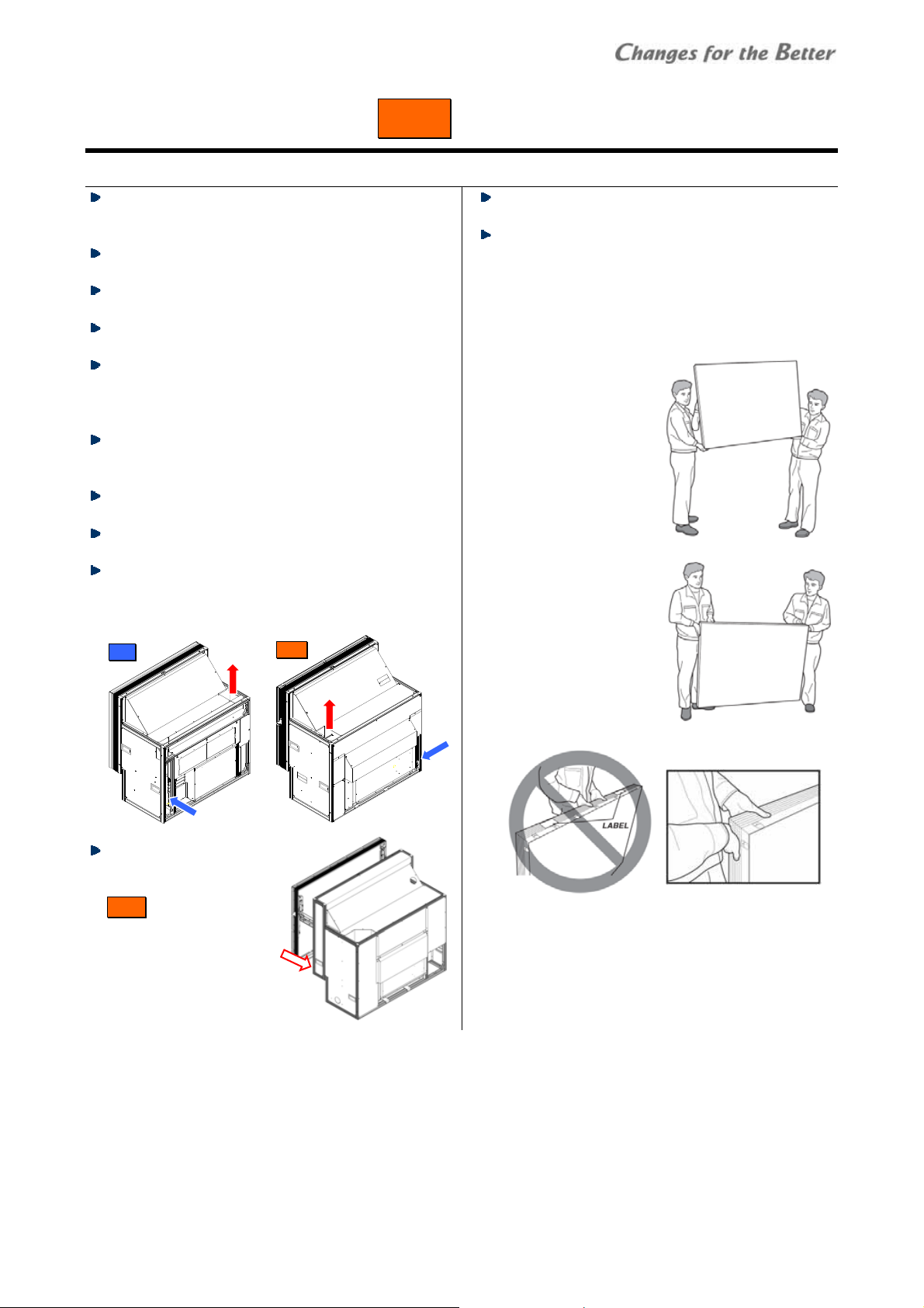
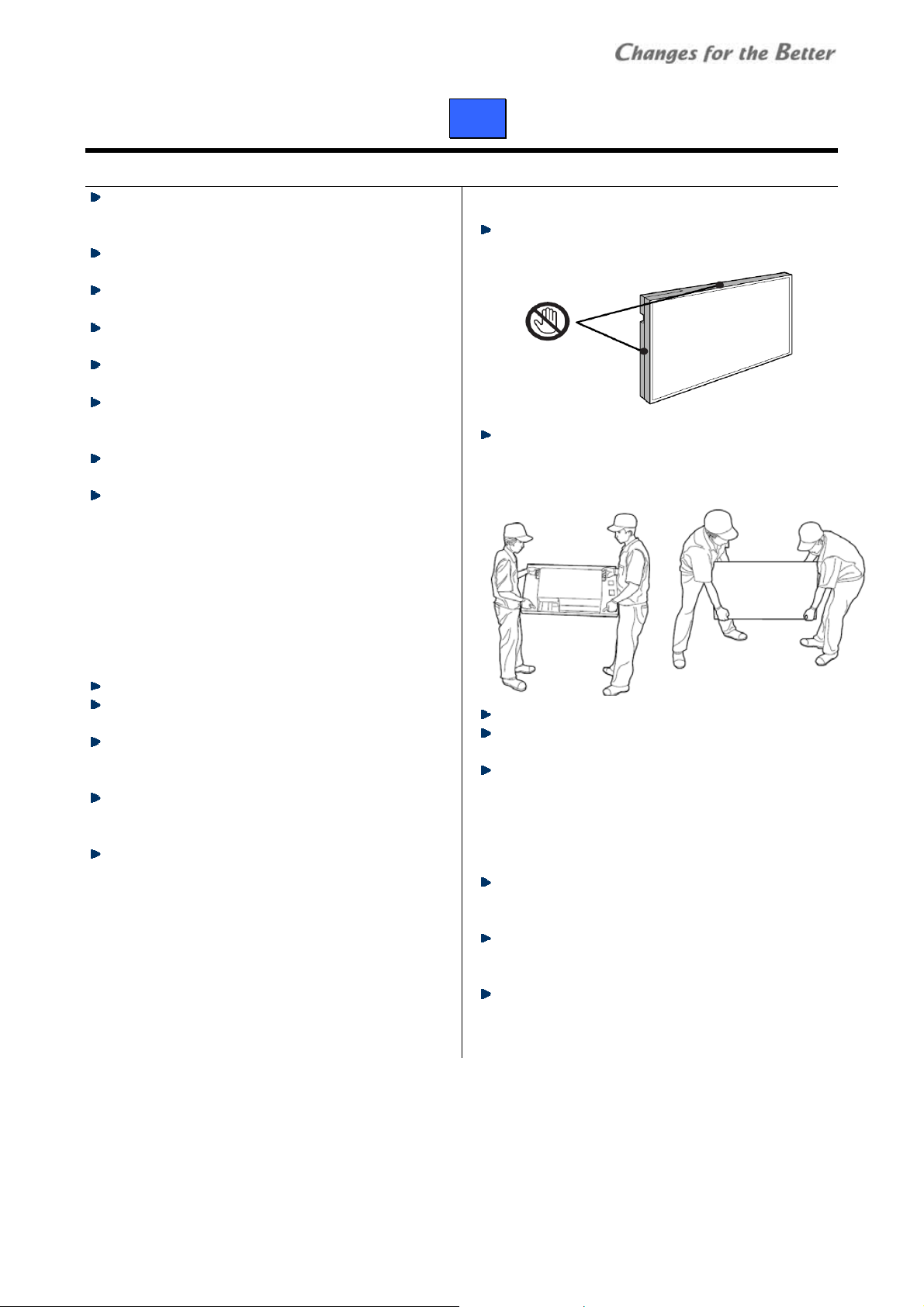
Handling instructions for 80” screen
Because 80” screens are large and heavy, the screens
should be held carefully.
• To prevent the screen
from damage or
breakage, carry the
screen by two or more
people.
• Hold the short sides of
the screen frame or the
corners when picking
up the screen. Holding
the center of the long
sides of the frame
(between labels) may
damage the screen
edge due to its heavy
weight.
• Do not lay the screen with face up on the floor or
table. The screen frames may not support the heavy
and large screen surface.
Safety precaution
REV 1.3 13
Page 14
Preparation
LED Safety LED
The LED engines are CLASS 2 LED products.
An exposure hazard may exist only if the protective
housing is removed.
Do not look into the LED light directly.
eyesight.
Use of controls, adjustments or performance of
procedures other than those specified herein may
result in hazardous radiation exposure.
• Specification of the LEDs
LED Wave length Pulse width
Red 623 nm 234 μs 41.24 mW
Green 525 nm 349 μs 26.43 mW
Blue 462 nm 218.3 μs 34.76 mW
• The LED light irradiation window is the projection
lens on the upper-center of the engine products.
Do not lens the LED light at anyone.
Looking at the LED light directly may damage
2
22..2
PPrreeppaarraattiioonn
2.2.1 Accessories
• Remove desiccant taped on the products. (no desiccant in engine integrated cubes)
• Remove a shipping protection sheet tucked in the lamp replacement door (page
• Make sure that all of the following items are supplied. • Prepare following tools.
Supplied accessories Q’ty per unit
Hex socket head bolts (M6) 8 (12 for 80”)
Flat washers (for M6) 8 (12 for 80”)
Spring washers (for M6) 8 (12 for 80”)
Seals for Joint holes 1
Control cable 1
User’s manual 1
Cable ties (Front )
6 (50”), 10 (60”, 67”)
Necessary tools
Hex keys 2mm, 2.5mm, 3mm, 4mm, 5mm
Phillips screwdrivers #0, #2
Level
Stepladder
Spacers (for screen gaps)
Wrenches (for base stands)
65).
Maximum
illumination power
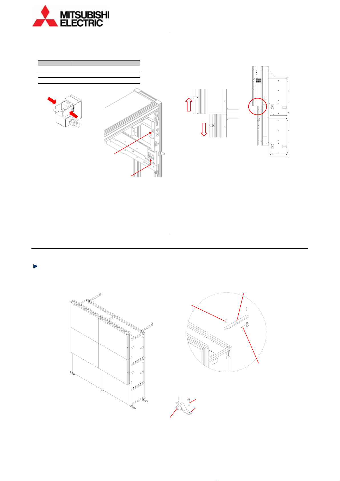
2.2.2 Input boards installation
Install input boards into the slots according to input
signal configurations.
• Be sure to turn off the main power switch before
installation.
• In Front , open the screen unit (page 20). The input
board slots are located inside the cubes.
1 Unscrew the 2 screws on the slots evenly with a hex
key (2.5mm) to remove the cover panels.
Screws
Cover panels
Input board slots
2 Insert input boards into the slots along their guide
rails.
3 Firmly fix the boards until the end by evenly and
alternately tightening the screws on both sides
removed in the step 1 (suggested torque: 0.7Nm). For
uninstalling the boards, reverse the procedure.
14 Seventy Series Set-up Manual
Page 15
2.2.3 Front attachment in 80” cabinet
This work is normally unnecessary.
When you pass the cubes through a narrow gate or
door, you can shorten the depth of the 80” cabinet by
separating the front attachment.
1 Remove the nylon washer with “C” shape on each
screen fixing bolt.
Screen fixing
bolt
2 Pull out the 4 screen fixing bolts from rear. Be sure
not to drop the washers attached to the tip of the
bolts.
Washe r
Nylon
washer
Front
attachment
3 Unscrew 4 hexagon socket head bolts (5mm) to
detach the front attachment.
Front attachment
Hexagon socket
head bolt
4 After passing through, reverse the procedure to
restore.
• Inside the front attachment, there are 4 connecting
plates which can be used as additional cube
connecting holes when making a curved display wall.
Prepare proper bolts, nuts and washers to connect
the cubes together through these holes. Unlike other
connecting plates on the main cabinet (page
19),
there is no castle nut inside the attachment.
Connecting plate
Preparation
REV 1.3 15
Page 16
Engine embedding
3
22..3
EEnnggiinnee eemmbbeeddddiinngg
Embed the engine units before cube installation (page 18) for separately supplied units.
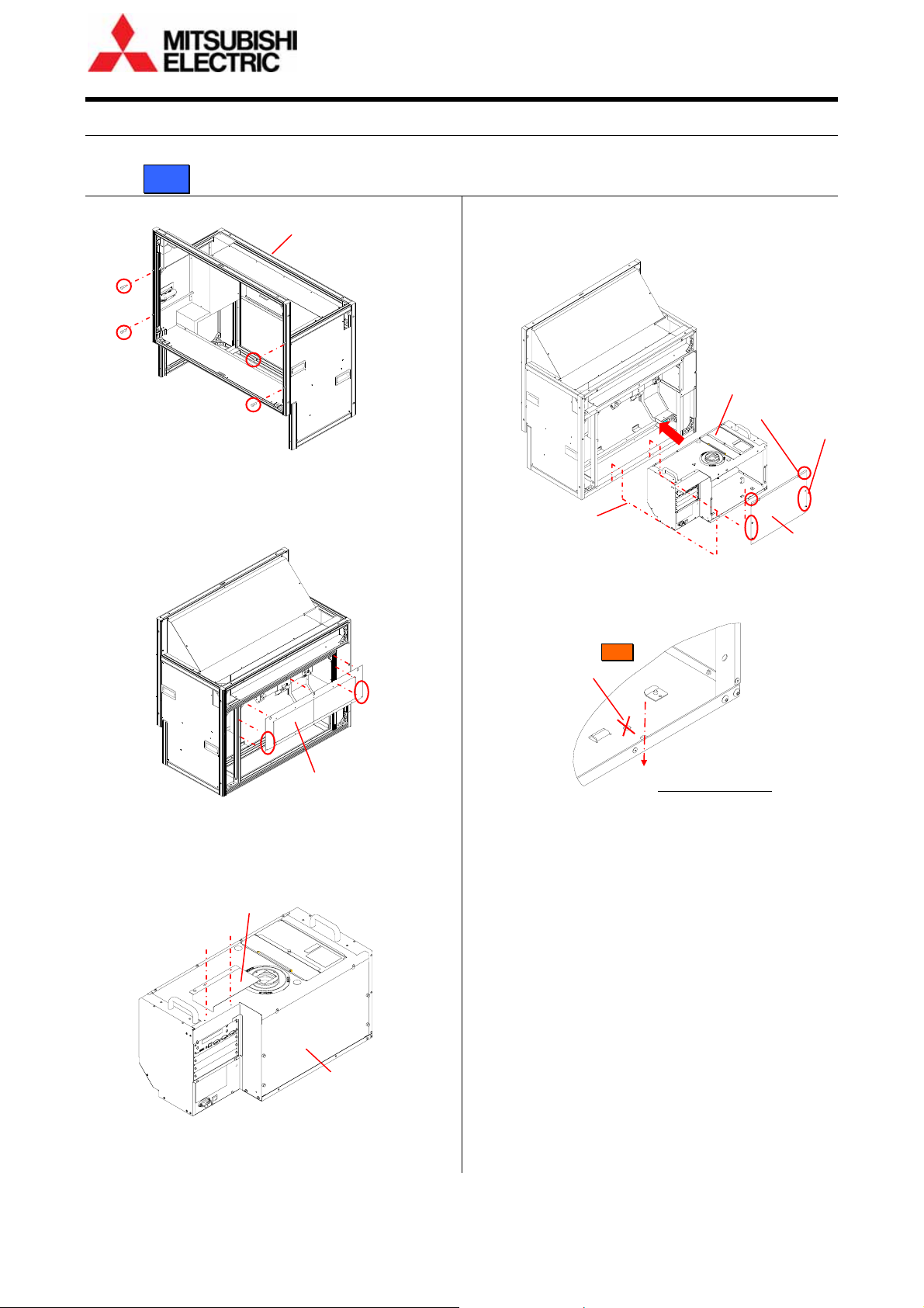
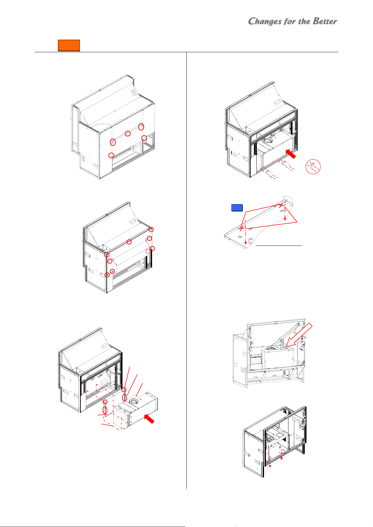
2.3.1 Rear
1 Remove 4 bolt caps from the cabinet.
Cabinet
Bolt caps
2 Loosen screws on the bottom edges of the rear panel
and lift the panel to remove.
• Three screws on the top edge are hooks and need
not to be loosened.
3 Attach a chassis cover, which is supplied with the
cabinet, on the top panel of the engine unit with 2
screws.
Chassis cover
Rear panel
Engine unit
4 Remove the rear panel of the engine unit.
Loosen 2 screws on the top edge, release 4 latches
and lift the panel to remove.
5 Insert the engine unit into the cabinet fully and fix it
with supplied 2 hex socket head bolts on both sides.
6 Put back the rear panels on both the engine unit and
the cabinet.
2 hex socket bolts
Holes for Front
(not in use)
Bottom of engine unit
Engine unit
2 screws
4 latches
Rear panel
2 hex socket bolts
(on left and right sides)
16 Seventy Series Set-up Manual
Page 17
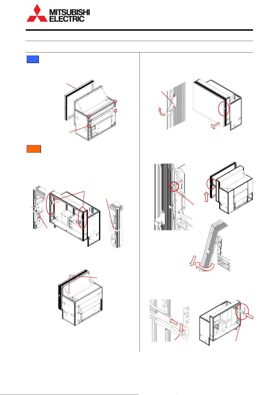
2.3.2 Front
1 Loosen screws on the rear panel and lift the panel to
remove. There is no need to unscrew them.
For 50”: Loosen 2 “A” screws and unscrew 7 “B” screws.
There is no need to unscrew “A” screws.
A
B B B
B
2 Remove the rear panel of the engine unit.
Loosen 2 screws on the top edge, release 4 latches
and lift the panel to remove.
2 screws
Rear panel
2 hex socket bolts
A
B
B
B
4 latches
Engine unit
3 Insert the engine unit into the cabinet fully and fix 2
metal brackets, which are supplied with the cabinet,
with 2 screws each.
2 brackets
Bracket shape
for 50"
4 Fix the engine with supplied 2 hex socket head bolts
on both sides.
Holes for Rear
(not in use)
2 hex socket
bolts
Bottom of engine unit
5 Put back the rear panels of both the engine unit and
the cabinet.
• The engine unit can be embedded from the screen
side as well.
1 In the same manner as above step 3, fix the 2 metal
brackets from the rear side.
2 Put the engine unit in the cabinet from the front side.
Be careful not to touch the mirror.
3 Fix the bottom of the engine unit on the cabinet in
the same manner as above step 4.
4 Put back the rear panel of the engine unit.
Engine embedding
REV 1.3 17
Page 18
T
T
Cube stacking
4
22..4
CCuubbee ssttaacckkiinngg
2.4.1 Screen demounting
Rear:
Loosen screen fixing bolts to demount the screen (in
screen integrated models).
Screen unit
Fixing
bolts
Front :
Unlocking
Release delivery locking before screen demounting /
mounting.
• Screen-holding arms (in screen separated models)
Peel off tapes from the screen-holding arms.
ape
• Shipping lock bolts (in screen integrated models)
remove 2 shipping lock bolts (M5-45mm, white hex
socket bolts).
Shipping lock bolts
Screen-holding arm
ape
Demounting
1 Pull up the screen handles on both sides to draw the
screen unit till locked and put the handles back to
the original positions.
Screen-drawing
handles
(1)
(2)
2 While pressing the release buttons on both sides to
the end, lift up the screen unit till it surely touches
the guides on both sides. Open the lower part of the
screen (about 15°) to pull it down on the skew.
Guide (on
both sides)
(2)
(1)
Release button
(on both sides)
(4)
(3)
3 Put back the screen-holding arms into the cabinet by
pressing down the slide lock lever (only on the right
side).
(2)
(1)
Slide lock lever
Screen-holding arm
18 Seventy Series Set-up Manual
Page 19
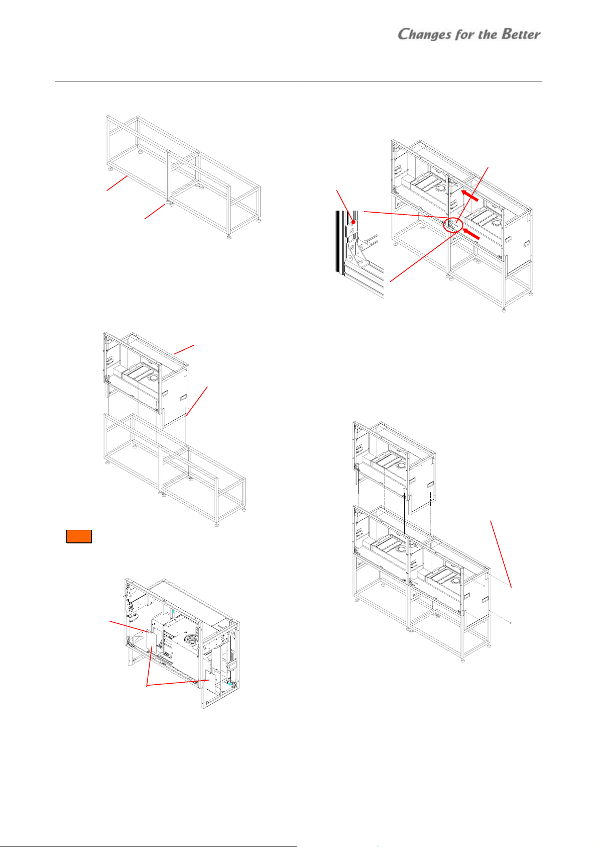
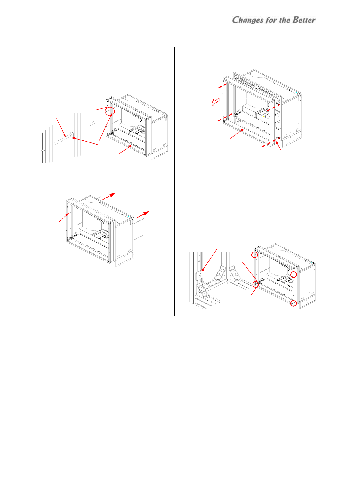
2.4.2 Base stands and cubes assembling
1 Make base stands both level and plumb by means of
a level.
2 Place a cube in the bottom row on the base stand.
3 Fix the cube at 4 points (8 points for 80”) with
4 Place a next bottom row cube on the base stand and
Base stands
Adjusters
supplied hex socket head bolts, spring washers and
flat washers.
• Tighten the bolts with appropriate force
(suggested torque: 3.9Nm).
Cube
Hex socket bolts
Spring washers
Flat washers
Front :
To access the rear fixing points, open the duct covers
on both sides by pulling the latch.
Latch
Duct covers
fix it in the same way.
5 Connect these cubes together at 4 points with
supplied hex socket head bolts, spring washers and
flat washers.
Connecting plate
Hex socket bolts
Spring washers
Flat washers
• When making a curved display wall and you have
to remove the connecting plates, put substitute
washers with equivalent strength on the holes.
6 Place other cubes for the upper row on the row of
cubes.
7 Connect these cubes vertically and horizontally in
the same manner as step 3 and 5.
Seals for Joint holes
• To prevent cubes from falling, make sure the cubes
are stably assembled by checking that they are
level.
8 After all cubes are joined together, stop up unused
holes on both sides of the cubes with supplied seals
for joint holes.
Cube stacking
REV 1.3 19
Page 20
Cube stacking
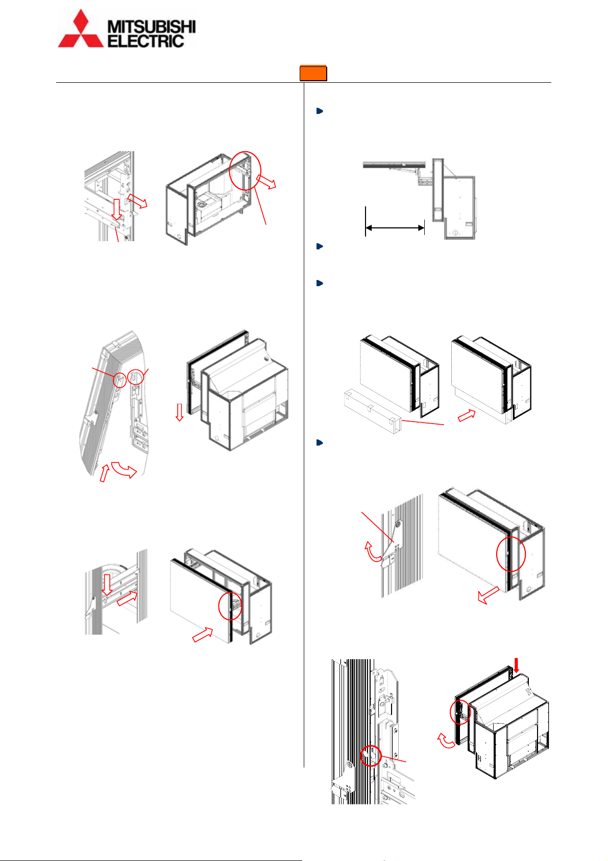
2.4.3 Screen mounting and open/close (Front )
Screen mounting
1 Draw the screen-holding arms from the cabinet till
locked while pressing down the slide lock lever (only
on the right side).
(1)
2 Mount a screen unit onto the cabinet.
Lift up the screen unit on a skew (about 15°) till the
part B surely touches the part A (guides) on both
sides. Make the screen upright rounding on the part
A to hang it on the arms.
(1)
3 Push the screen unit along the rails till the end while
pressing down the slide lock lever (only on the right
side).
(1)
(2)
Screen-holding arm
Slide lock lever
A B
(3)
(2)
(2)
Slide lock lever
Screen opening
1 Pull up the screen handles on both sides to draw the
2 Press down the open switch on the left at first which
About one-meter space is needed in front of the
screens for the opening. Prior to work, make sure
that there is no object such as steps in the working
space.
Open/close the screen units one-by-one in a display
wall with making sure if adjacent screens are surely
shut so as not to shift the center of gravity too much.
To prevent cubes from toppling during screen
open/close, use the support base contained in the
cube carton boxes when the cubes are not fixed to a
base stand or other cubes.
Support base
Be careful not to trap your fingers during the work.
screen unit till locked and put the handles back to
the original positions.
Screen-drawing
handles
(1)
(2)
will be locked. While pressing down the other open
switch on the right, pull up the lower part of the
screen to open.
Open switch
(left)
(1)
(3)
(2)
Open switch
(right)
20 Seventy Series Set-up Manual
Page 21

Screen closing
Be careful not to trap your fingers during the work.
1 Push down the lower part of the screen lightly till
locked.
2.4.4 Screen gaps adjustment
Rear:
1 Lightly fix a screen unit on the cabinet with 4
screen-fixing screws.
2 Adjust the screen gaps with spacers to be as follows:
50”: 1mm / 60”: 1.5mm / 67”: 2mm / 80”: 3mm
Screen gap
3 Tighten the 4 screen-fixing screws with appropriate
force (suggested torque: 3.9Nm).
Screen unit
Fixing screws
Screen gap
2 Push the screen unit along the rails till the end while
pressing down the slide lock lever (only on the right
side).
(1)
(2)
Slide lock lever
• The screen unit may touch adjacent screens
depending on the screen gap adjustment. Adjust the
gaps appropriately.
Front :
1 Open the screen unit.
2 Loosen 5 fixing screws for screen adjustment with a
hex key (3mm) (fixing screws: 1 for horizontal, 2 for
vertical on each side).
3 Optional motor unit (S-MA70E) allows you to adjust
the screen gaps by remote control. Connect the
motor unit to the cube in reference to “Mirror
correction (page
41).
Motor units
L
R
PR
H. fixing screw
2 V. fixing screws
(on both sides)
Drive unit
Cube stacking
REV 1.3 21
Page 22
Cube stacking
4 Snap the motor units in the screen adjustment
screws.
• The motor unit of PL is not used for the gap
adjustment.
Screw Motor unit Menu
Vertical (left) L SCREEN-L
Vertical (right) R SCREEN-R
Horizontal PR SCREEN-H
H adjusting screw
V. adjusting screws (on both sides)
5 Display SYSTEM SETTING > MAINTENANCE > MECH
ALIGNMENT menu.
6 Shift the screen position from side to side and up
and down so that the screen gaps will be as follows:
50”: 2mm / 60”: 2.5mm / 67”: 3mm
• The screen is rotated by different travel distance on
both vertical adjustment screws.
7 After the adjustment, tighten the 5 fixing screws
which have been loosened in the step 2.
• The screen unit may touch adjacent screens
depending on the gap adjustment. Adjust the
gaps appropriately.
Manual adjustment
The gaps can be adjusted manually as well. Turn the
adjustment screws with a hex key (4mm) instead of the
motor units. One turn of the screws shifts the screen
approximately 0.8mm.
Close the screen unit to check the gap and repeat the
steps until being appropriate. Tighten the 5 fixing
screws after the adjustment.
2.4.5 Fixing to the wall and floor
1 Firmly fix the base stands onto the floor by means of fixing brackets and/or anchor bolts.
2 Fix the upper back part of the cubes to the wall behind by means of fixing brackets.
To prevent the cubes from falling due to unpredictable events such as earthquakes or shocks, fix them firmly to
the wall and floor. Furthermore, carefully confirm the strength of the fixing areas (wall and floor) of the installation
room. The fixing method differs depending on the number of cubes.
Adjusters
After the completion, proceed to “Adjustment” (page
Bolts
Anchors
Floor-fixing brackets
32).
Wall-fixing brackets
Bolts
22 Seventy Series Set-up Manual
Page 23
3
3
LLCCDD ppaanneell iinnssttaallllaattiioonn (
1
33..1
SSaaffeettyy pprreeccaauuttiioon
This product requires special installation to prevent
falling or toppling. This should be done by
installation specialists.
Be sure to read this manual and the user’s manual for
your safety before starting assembly or installation.
Be sure to use supplied accessories for assembly or
installation.
Attach all the screws and fixtures specified in this
manual securely.
Do not dissolve or revamp the product except the
areas which are specified in this manual.
Do not install this product on an inclined place or
unstable place. The product may drop or fall over
which may cause injury.
Do not install this product on its side, upside down,
on its rear, face down, or in a slanting position.
Do not use the product under the following
circumstances, which may cause fire or electric
shock.
• in a dusty or humid place
• a place where airstream from something like air
conditioning directly blows to an exhaust vent in
the product.
• in a oily, smoky or damp place
• near a heater
• in a vibratory area
Do not use this product outdoors.
Inspect the mounting fixings more than once in a
year as needed.
Do not install the product with its intakes, exhaust
slots and ventilation holes blocked. The unit may
overheat and cause a fire or breakdown.
Be sure to mount/demount the screen by 2 or more
people. These works may be perilous particularly on
a height or a narrow scaffold.
Unplug immediately if there is something wrong
with your product.
n
(
LLCCD
D
))
How to handle the LCD panels
Do not touch the top surface or left-hand surface as
viewed from the front surface of the product. Doing
so may cause failure.
When carrying the product, make sure to have two
people carry it while holding onto the handles. In
addition, being careful not to tough the panel screen,
cautiously support the bottom surface of the panel.
Be careful not to twist or bend the product.
Be careful not to bump or apply pressure on the
panel.
When laying the product flat, be sure to place the
panel on a flat surface with a something soft like a
blanket underneath, and be careful not to scratch
the surface of the panel or allow the panel to be
subjected to excessive pressure. Also do not leave
the panel face-down for a long while.
Protect the panel from static electricity.
To keep static buildup to a minimum, remove the
protective sheet on the panel surface slowly.
The surface of the panel is rather fragile and can be
damaged easily. Do not push down hard on it or
scratch it.
Immediately wipe away any drops of water or oil that
adhere to the panel. Allowing water or oil to remain
on the panel for long periods of time may result in
the panel becoming stained or changing color.
Safety precaution
REV 1.3 23
Page 24
Preparation
2
33..2
PPrreeppaarraattiioonn
3.2.1 Accessories
Make sure that all of the following items are supplied.
Supplied accessories Q’ty per unit
Control cable 1
User’s manual 1
Cable ties 5
3.2.2 Input boards installation
Install input boards into the slots according to input signal configurations
• Be sure to turn off the main power switch before installation.
1 Place the panel on a flat surface with a
something soft like a mattress or blanket
underneath.
• Do not leave the panel face-down for a
long while.
2 Unscrew the 2 screws on the slots evenly
with a hex key (2.5mm) to remove the
cover panels.
3 Insert input boards into the slots along
their guide rails.
4 Firmly fix the boards until the end by
evenly and alternately tightening the
screws on both sides removed in the step 1
(suggested torque: 0.7Nm). For
uninstalling the boards, reverse the
procedure.
Slot 3
Cover panel
Slot 1
Slot 2
Screws
3
33..3
MMoouunnttiinngg
3.3.1 For using commercial wall mount brackets
The product is equipped with screw holes on its back
side to be fixed with a commercially available wall
mount brackets. You can use a bracket which is
compliant with VESA300.
Caution for installation
Mechanical structure
Be sure to read “safety precaution” in this manual
23) and follow the instruction.
(page
Be sure to read the bracket’s instruction manual and
installation procedure as well as this manual.
Use a bracket which can bear 4 times or more weight
of the product. When the strength is unsure, put a
90kg weight on the product and check if it is held
stably for 1 minute.
Before mounting, check the strength of the wall.
Mount on a wall which safety factor is more than 10
(or ensure that it can bear ten times the weight of
products and the brackets). When it is not sufficient,
reinforce the wall surface. (The weight of
VS-L46XM70U: about 30kg)
Carefully install onto the wall not to get loose due to
vibration etc. Wrong installation or installation with
insufficient strength causes the product to fall
resulting in a serious accident or injury.
The weights shall be borne by a sturdy structural
material such as a joist. Secure the bracket using
bolts, spring washers, washers, and nuts.
Don’t install the bracket directly on a wall having
insufficient strength, or don’t install it using wooden
screws or anchor screws. Also don’t install it on
wooden structural materials or blocks.
Ensure that the safety factor per bolt is more than 10
(or ensure that the total bolts bear the weight ten
times the sum of the weights of the products and the
brackets).
Install the products not to touch with adjacent
panels. The outer circumference of the panels is quite
weak and hard pressure or impact may cause
damage.
For future maintenance, it is recommended that the
product be installed so that it can be taken out of the
bracket easily.
24 Seventy Series Set-up Manual
Page 25
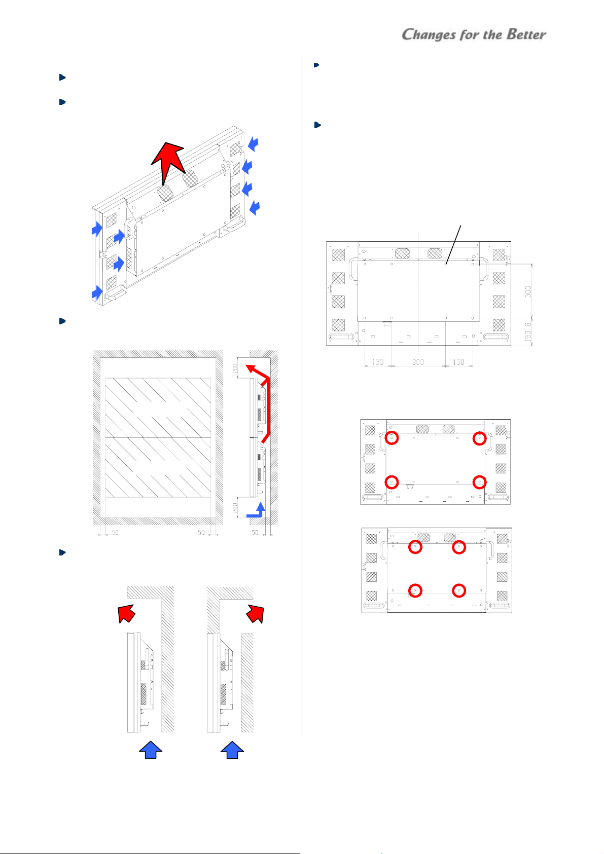
Ventilation
Refer to “Image persistence” (page 70) for ventilation
concept.
Don’t block the ventilation holes. The temperature
inside the product rises high causing a fire or
breakdown.
Exhaust
Intake
Intake
To ensure a proper airflow for cooling, create a space
around the products at least as shown below (unit:
mm).
Panel
Panel
Exhaust hot air gets stacked above the product.
Design the structure so as to release it and flow
enough fresh air in from the bottom as shown below.
Exhaust
Intake
In high configurations, the temperature condition
gets worse in the upper panels. The recommended
stack number is up to 6. When over that
configuration, it requires an additional ventilation
way to enhance the efficiency.
Operate under the range of 5 to 30 centigrade
conditions when the panels are used in BRIGHT
mode (page
48).
Mount holes for brackets
You can use a bracket which is compliant with VESA300.
Utilizing 8 screw holes (M6, 10mm depth) on the back
of the product, mount it on a bracket.
• At least use 4 screw holes to mount as shown below.
To prevent from drop-off, it is recommended to use
rest of holes as well.
4 points outside
Or 4 points inside
• Use appropriate screws with 10mm or less.
Otherwise, it may be imperfect fixing or it may
damage the nuts inside the products.
Proceed to “IR receiver attaching” (page
8 screws
31).
Mounting
REV 1.3 25
Page 26
Mounting
3.3.2 For using optional wall mount frame (BR-XM70KK)
Caution for installation
Mechanical structure
Be sure to read “safety precaution” in this manual
23) and follow the instruction.
(page
Before mounting, check the strength of the wall.
Mount on a wall which safety factor is more than 10
(or ensure that it can bear ten times the weight of
products and the wall mount frames). When it is not
sufficient, reinforce the wall surface. (The weight of
VS-L46XM70U: about 30kg, BR-XM70KK: about 25kg)
Carefully install onto the wall not to get loose due to
vibration etc. Wrong installation or installation with
insufficient strength causes the product to fall
resulting in a serious accident or injury.
The weights shall be borne by a sturdy structural
material such as a joist. Secure the wall mount frame
using bolts, spring washers, washers, and nuts.
Don’t install the wall mount frame directly on a wall
having insufficient strength, or don’t install it using
wooden screws or anchor screws. Also don’t install it
on wooden structural materials or blocks.
Ensure that the safety factor per bolt is more than 10
(or ensure that the total bolts bear the weight ten
times the sum of the weights of the products and the
wall mount frame).
Before installation, calculate cable length for external
connection and prepare them. Inappropriate length
may make the wiring difficult.
Ventilation
Refer to “Image persistence” (page 70) for ventilation
concept.
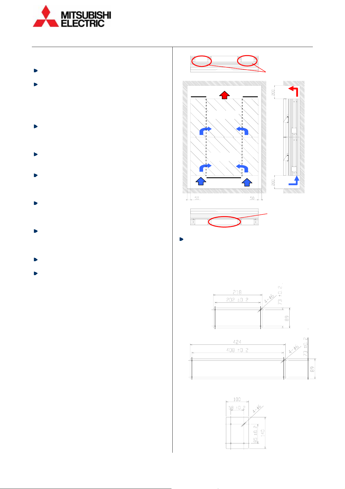
To ensure a proper airflow for cooling, create a space
around the products at least as shown in the right
top figure (unit: mm). Also block 2 exhaust vents on
each frame of the top row and one intake vent per
frame on the bottom row.
Prepare the covers by yourself in reference to the
figures below (unit: mm). They can be fixed with 4
screws (M4, 10mm or more length) through holes on
the wall mount frame (suggested torque: 0.7Nm). Do
not block other vents.
Material (example): aluminum or steel plate with
1mm thickness
• Top cover
• Bottom cover
• Side cover (if you cover unused cabling holes on
both sides of the display wall)
Panel
Panel
Blocked 2 exhaust
vents (only on the
top row)
Blocked intake
vent (only on the
bottom row)
26 Seventy Series Set-up Manual
Page 27

Exhaust hot air gets stacked above the product.
Design the structure so as to release it and flow
enough fresh air in from the bottom as shown below.
Exhaust
Intake
In high configurations, the temperature condition
gets worse in the upper panels. The recommended
stack number is up to 6. When over that
configuration, it requires an additional ventilation
way to enhance the efficiency.
3.3.3 Arrangement
1 Create following mount holes on the wall (unit: mm).
4 M6 holes for wall mount frame
Wall mount frame outline
2 Remove 6 shipping lock bolts (both sides), 2 handles
and 2 joint brackets.
2 joint brackets
2 handles
6 shipping lock bolts
3 Place the panel on a flat surface with a something
soft like a mattress or blanket underneath.
• Do not leave the panel face-down for a long while.
2 dia. 6mm guide holes
4 M6 holes
for hooks
Operate under the range of 5 to 30 centigrade
conditions when the panels are used in BRIGHT
mode (page
48).
Accessories
Make sure that all of the following items are supplied
with the wall mount frame.
Supplied accessories Q’ty per unit
Hooks 2
Hook fixing screws (M6x12) 4
Fixing bolts (M6x30) 4
Fixing washers (dia. 25mm) 4
Link bolts (M6x45) 4
Cable ties 10
User’s manual 1
Prepare following tools.
Necessary tools
Hex keys 4mm, 5mm
Phillips screwdrivers #2
Wrench (8mm)
Level
Stepladder
4 Attach the joint brackets on the panel, which
brackets have been removed in the previous step.
Use removed 3 shipping lock bolts each to fix them.
• Carefully work not to bear down on the LCD panel
hardly.
Joint bracket
(on both sides)
5 Likewise, attach the removed handles on the panel
sides with the screws that fixed them on the wall
mount frame. When attaching, contact inside the
handle with the side of the panel closely.
6 Attach the 2 hooks per panel on the wall with
suppied hook fixing screws.
Hook
Hook fixing screws
Handle
(on both sides)
Mounting
REV 1.3 27
Page 28

Mounting
3.3.4 Wall mount frame attaching
At first, attach the frame at the center of bottom row,
then its both sides and go to upper rows.
(7) (8)
(4) (5)
(1)
(1) (2)
1 Hang the frame at the center of bottom row (1) on
the hooks.
2 Shift the position of the frame to fit the guide holes
on the wall. Take a level of the frame. If M6 screw is
inserted at the bottom of each hook, it can lift the
frame to tweak the vertical position.
• Remove the screws after adjustment.
Guide hole Hook
3 Fix the frame on the wall with supplied 4 fixing bolts
and washers.
(9)
(6)
(3)
M6
screw
4 In the same manner as step 1, hang the mount
frames on the both sides ((2) and (3)) on the hooks.
Align the level and height with the center frame (1),
and fix them on the wall temporaliry.
• If M6 screw is inserted at the bottom of each hook,
it can lift the frame to tweak the vertical position.
Remove the screws after adjustment.
5 Connect these frames each other with supplied link
bolts then fix them firmly on the wall.
6 Also in the same manner, attach the frame at the
center of upper row (4). Connect with the lower
frame and fix firmly on the wall.
7 Attach the frames on the both sides of it ((5) and (6)).
Align the horizontal positions with the lower frames
and connect with them and the side frames as well.
Fix them on the wall firmly.
8 Repeat the procedure to attach all frames. Make sure
that they are aligned vertically and horizontally also
their front surfaces are in one flat plane.
3.3.5 Preliminary internal cabling
Before mountig the LCD panels, pre-arrange the cables for all panels in
reference to “Connecting” (page
located on both sides of the frames in consideration of the redundant cable
length for the panel slide distance to the front.
Divide the cable lines as appropriate according to the cable number and length.
Basically signal cables are left side and power cords are right side.
• If you clamp the cables to fix on the inside the frame with supplied cable ties,
it facilitates smooth panel open / close (page
• The cable holes on top and bottom also have a function of airflow vents.
When the cables occupy the opening, tie them in the vicinity of the hole for
space-saving.
28 Seventy Series Set-up Manual
32). Run the cables through the cable holes
29).
Cable holes
Cable holes
Cable ties
Page 29

T
p
T
p
(7)
(3) (5) (8)
3.3.6 LCD panel mounting
At first, attach the panel at the center of middle row,
then spread it out to adjacent panels on both sides and
top / bottom. Lastly attach the ones in other areas.
(1) (2)
(1)
(4) (6)
1 Press the unlock switches on both sides of the wall
mount frame.
2 Draw the front bar to the front until locked.
Unlock
switches
Front bar
3 Hang the joint brackets in the back of the panel on
the front bar so as to fit the hole and the protrusion
toghether.
• Carefully treat the panel not to touch with adjacent
panels.
(9)
Hole
Protrusion
Fixing bolts
and washers
(both sides)
4 Temporaliry fix the panel with fixing bolts and
washers which were on the joint brackets.
• Screen gaps could not be adjusted if you fix it
firmly.
5 Connect the cables to the panels.
6 Not to run the cables off the bottom edge when the
panel is closed, tie the cables with supplied cable
ties.
o clam
o clam
Power cord Cable ties
Cables
Mounting
3.3.7 Panel open / close
Panel closing
Push the panel lightly to slide till locked at the end
while turning the unlock knob clockwise located on
the right side of the wall mount frame.
• Close it carefully not to touch adjacent panels.
• Make sure that the closed panel doesn’t pinch the
internal cables.
Unlock knob
Panel opening
Pull up the handes on both sides 90 degrees to draw
the panel till locked.
Put the handles back to the original positions after
drawing.
Handles
(both sides)
REV 1.3 29
Page 30

T
T
Mounting
3.3.8 Panel gap adjustment
Flat surface shift
Utilizing optional adjustment tool (the combination of
motor units (S-MA70E) and motorized adjustment tool
(MAT: S-A70E)), the gaps between the panels can be
adjusted by remote control or Wallaby.
1 Set the slide switch to [OPE] on the drive unit of the
MAT (S-A70E).
• Switch them before connection to panels.
• No need to change the switch on the left side.
2 Loosen the screw in the lid for adjustment tool on
back side of the panel, and open the lid by 90 degree
rotation. You don’t need to remove the screw.
3 Connect the drive unit to the connector inside the lid
with a supplied cable with the MAT as well as to the
motor units.
4 Attach the motor units of R, L and PR on the
following points. By pinching metals on the motor
units, snap the tips of them into rectangular holes
beside the adjusting screws.
• The motor unit of PL is not used for the gap
adjustment.
Screw Motor unit Menu
Vertical (left) L SCREEN-L
Vertical (right) R SCREEN-R
Horizontal PR SCREEN-H
REAR WRITE OPE FRONT
Connector for MAT
o motor units
o panel
V. posi tion
(both sides)
H. position:
PR
V. posi tion : R
(other side: L)
• Not to be pinched by panel open / close, carefully
arrange the cables as below.
PR
R
L
5 Display SYSTEM SETTING > MAINTENANCE > MECH
ALIGNMENT menu.
6 Shift the panel position from side to side and up and
down to adjust the gap width.
• The panel is rotated by different travel distance on
both vertical adjustment screws.
• Keep appropriate gaps so that the panel can slide
back and forth. The wall mount frame is designed
1mm bigger (0.5mm each on 4 edges) than the
panel outer dimension.
7 After the adjustment, take out the MAT and surely
close the lid of its connection port by tightening the
screw on it.
Manual adjustment
The gaps can be adjusted manually as well. Turn the
adjustment screws with a hex key (4mm) instead of the
motor units. One turn of the screws shifts the panel
approximately 0.8mm.
Close the panel to check the gap and repeat the steps
until being appropriate.
30 Seventy Series Set-up Manual
Page 31

Front / back direction
Loosen the nuts on the adjustment screws before
adjustment. Turn the screws with a hex key (4mm).
There are 4 screws in total on both sides. One turn of
the screws shifts the panel approximately 1.5mm.
Tighten the nuts after the adjustment.
• The shifting direction is opposite on upper and
lower screws. By clockwise turning, the upper
screws shift the panel to the back and lower screws
to the front.
3.3.9 IR receiver (R-XM70IR) attaching
Optional IR receiver allows you to control the panel by
remote control wirelessy.
• There is no need to change the dipswitch setting on
the panel.
• The IR receptor on the left side of the panel cannot
receive the signal from the panel front.
• Even without the receiver, the supplied cable with
the remote control can be connected to the wired
remote control port on the panel to control it
directly.
Accessories
Make sure that all of the following items are supplied
with the IR receiver.
Supplied accessories Q’ty per unit
Cable (2m): JC-RC2M 1
Screws (M4x10) 2
Attaching
1 Connect a connect port on IR receiver and the wired
remote port on the MASTER panel (page
supplied cable. The Master panel directs other panels
through the control cables.
• The receiver has 2 ports. You can use any of them.
The other one will be a wired remore control port.
Connect ports
Acceptance surface
33) with the
Fixing bolts and washers
(both sides)
Nuts
Adjusting screws
(4 points)
After all adjustment, firmly tighten the fixing bolts and
washers on the joint brackets on both sides which have
been fixed temporarily.
2 Fix the receiver as its acceptance surface faces to the
front on a surrounding structure or at the screw
holes on each edge of the panel (There are 5 holes
on each top / bottom and 3 holes on each side) with
supplied screws. Carefully work not to put an
execcive pressure on the bezels.
IR receiver
(example)
Wired remote control port
Mounting
REV 1.3 31
Page 32

Initial setting
4
4
AAddjjuussttmmeenntt
1
44..1
IInniittiiaall sseettttiinngg
4.1.1 Connecting
Internal control cables connection
From the MASTER monitor (page 33), cascade
CONTROL OUT and CONTROL IN ports between
monitors in sequence with supplied control cables.
Communication between monitors automatically
corrects the brightness for uniformity (SENSOR
function: page
by remote control can control other SLAVE monitors
through the line.
Master
Slave
• Up to 98 monitors can be connected.
• Do not connect to a closed-loop.
• Connect the control cables even when controlling
monitors through network.
47). Also the MASTER monitor directed
To n ext CO NTROL
IN port
Slave
Slave
External control cables connection
External controllers such as personal computers in
which adjustment software, Wallaby has been installed
can control monitors.
• Through RS-232:
Connect the external controller to the MASTER monitor
33) with RS-232 cross-over cable. The controller
(page
will be able to control the monitors individually
through the internal control line.
• Through the network:
Connect external controllers to all monitors through a
network. A unique IP address can be assigned to each
monitor (page
36).
Master
Slave
Slave
Slave
192.168.100.32
192.168.100.34
192.168.100.33
192.168.100.35
Image signals connection
Connect image input sources to monitors according to
input signal configurations to be displayed. Refer to
Display memory setting” (page 59) for the detail of
“
available image window layout patterns.
Internal cabling (Front )
Run cables through the cable covers located on both
sides and top/bottom of a cabinet.
Punch a hole in the center slit of the covers at
necessary points for the cabling.
Mount
base
Clamps
(60”, 67”)
Mount
base
• To block dust, do not break the covers on the outer
sides of a display wall.
For the safety reason, do not leave a power strip
inside the cabinet.
For vertical cabling:
Draw supplied plastic cable ties through the holes in 3
units of mount bases located on the left surface inside
the cabinets and fasten the cables with them. For 60”
and 67” cabinets, fasten with 2 additional ties in the
middle of the cables in the air.
For horizontal cabling:
Draw the ties through the holes in 5 units (3 units for
50”) of mount bases on inside the skirt part and fasten
the cables with them.
Covers
32 Seventy Series Set-up Manual
Page 33

4.1.2 Dipswitch setting
Set the dipswitches
adequately according
1 2 3 4 5 6 7 8
to system
configurations.
• The switches No. 1 through 3, 5 and 6 normally don't
need to be changed. (The function of each switch is
mentioned on page
81.)
• Change the switches while the power is off. Turning
on the main power switch renews the setting.
Wireless remote control invalidation
Switch No. 7 (ON: valid, OFF: invalid, initial setting:
Cube ON, LCD OFF)
It can be used to prevent wireless remote control, i.e. to
avoid controlling the wrong monitor.
In LCD , set it ON when you use the IR receptor on the
left side of the panel. Remain OFF to use the optional IR
receiver (R-XM70IR) (page
31).
ON
OFF
MASTER / SLAVE setting
Switch No. 8 (ON: MASTER, OFF: SLAVE, initial setting:
ON)
Set a monitor as MASTER in a display wall and others as
SLAVE. The Master monitor collects information from/
directs toward SLAVE monitors.
Master
Slave
Slave
Slave
Low color temperature mode LED
Switch No. 4 (ON: low color temperature mode, OFF:
normal, initial setting: OFF)
It can display in low color temerature. Set the same
mode in all monitors in the display wall. To adjust the
temerature further, adjust it with WHITE BALANCE
menu (page
46).
Initial setting
4.1.3 Power-on
1 Turn on the main power switch underneath the
control panel. The monitor goes to standby state.
• ON setting of SYSTEM SETTING > MISC. 1 > AUTO
POWER ON automatically starts the start-up
process (page
49).
2 Press [POWER ON] button on the remote control or
press-and-hold the standby switch on the control
panel. It starts the start-up process.
4.1.4 Focus adjustment ( Cube )
Soft focus can be adjusted.
• Adjust the focus before geometry adjustment (page
38). The focus may shift the geometry.
• The focus on the engine products is adjusted for 67”
cubes.
Focus ring
Guide label
2 fixing screws
Cube will be in-service in a few ten seconds and the
status indicator shows “POWER ON”. LCD will be
in-service in over ten seconds.
Power socket
Main power switch
1 Press [TEST] button twice on the remote control in
advanced mode to show the crosshatch pattern.
2 Remove the rear panel of the engine unit.
3 Loosen 2 focus fixing screws on the projection lens
with a Phillips screwdriver (#0).
4 Turn the focus ring to balance the focus between
image center and four corners in reference to screen
size indication on the focus guide label.
• In consideration of backlash, turn the ring to the
arrow direction on the label. To go to other way,
turn to the opposite direction longer and turn back
to the arrow direction.
• In Front, close the screen unit (page 21), to check
the focus and repeat the above steps until being
appropriate.
5 Tighten the focus fixing screws on the projection
lens with appropriate force (suggested torque:
0.2Nm).
6 Restore the rear panel of the engine unit.
REV 1.3 33
Page 34

Initial setting
4.1.5 Wallaby
“Wallaby” is a software program that can adjust
Mitsubishi display walls through RS-232 or network
communication. Up to 98 monitors in a display wall can
be controlled separately without the remote controls.
Set the Wallaby in the following steps when you
control the monitors with the software.
This software works with Microsoft® Windows NT®
Version4.0, Windows® 2000, Windows XP and Windows
Vista.
Wallaby installation
Execute the “Setup.exe” file in the set-up folder on a PC
to install the Wallaby software. Follow the messages to
complete the installation.
Connection
According to “External control cables connection”
32), connect the control PC to a display wall. To
(page
connect through the network, allocate an appropriate
IP address onto the PC which can comminute with the
display wall.
192.168.100.32 192.168.100.33
192.168.100.31
(an example)
192.168.100.34
192.168.100.35
Unit ID, IP address assignment
According to “System memory setting (basic)” (page 36),
Set unit IDs and IP addresses on the monitors with
remote control in advance. Without applicable IP
addresses on monitors, Wallaby cannot communicate
with the monitors through the network.
• Once the network is established, the IP addresses can
be changed from Wallaby.
Start-up the application
Run the Wallaby software in Windows® start menu etc.
34 Seventy Series Set-up Manual
Page 35

System configuration
System > Configuration
Put the information of the monitor configuration to
Wallaby.
Display Layout
1 Model: select the monitor model to control
2 Horizontal, Vertical: set horizontal and vertical
monitor numbers respectively.
3 “Apply” button shows designated number of panels
on both panel area and monitor select area.
Panel area
Cube select area
ID and IP address
Unit IDs and IP addresses can be assigned to Wallaby,
which numbers have been set in the monitors. You can
modify them to suit the monitor setting accordingly.
• The unit IDs and IP addresses on the monitors need
to be set with remote control preliminarily (page
36).
• They are automatically allocated in a sequential order
from the upper left panel when the Display Layout
setting is applied.
ID 1
192.168.100.32
ID 2
192.168.100.33
ID 3
192.168.100.34
ID 4
192.168.100.35
Follow the procedure below if you change the
allocated preset unit IDs and IP addresses.
1 Select the upper left panel in the display wall
configuration on the panel area or monitor select
area. This panel will be the base point to allocate the
numbers.
2 Enter (or select) the ID number / IP address for the
base point panel.
3 Click “Sequential Numbering” button. The unit IDs
and the IP addresses are automatically allocated in a
sequential order from the upper left panel.
When you modify it individually, select the target panel
and enter (or select) the new ID number / IP address.
Communication
1 Choose the communication method out of “LAN” or
“RS232C”. Set COM port and communication speed
adequately when you choose “RS232C”.
2 Make sure that the main power switch on the
monitors has been turned on.
3 Check on “Connect” to connect with the monitors.
When the connection is establishment, the panels
will be blue. Other panels will be gray.
• When connected, the pixel coordinates setting (H.
LOCATION, V. LOCATION: page
37) is overwritten
on the monitors according to the configuration in
Display Layout setting in Wallaby. You need to be
careful if you assign a different configuration to
Wallaby from the real one. It may change the
monitor setting.
Initial setting
REV 1.3 35
Page 36

System memory setting (basic)
2
44..2
SSyysstteemm mmeemmoorryy sseettttiinngg ((bbaassiicc))
Monitor conditions can be adjusted in system setting
menus. The settings apply to the entire screen on the
monitor and one condition is memorized in the
monitor.
Pressing-and-holding [MENU2] button in the remote
control shows SYSTEM SETTING menu. Or select
TOP
SYSTEM SETTING
INSTALLATION
H. LOCATION Horizontal space coordinates assignment
V. LOCATION Vertical space coordinates assignment
UNIT ID Unit ID number assignment
TCP IP IP address assignment
MISC. 2
IMAGE FLIP Cube
SYSTEM SYNC. Sync. Frequency setting on monitor
SYSTEM SETTING SAVE System memory save (page 37)
Image flip setting
SYSTEM SETTING in TOP menu.
Normally, check and adjust these basic setting items in the right chart. The monitors can be customized with custom
setting items (page
48) as necessary.
• Unit IDs and IP addresses should be set with the remote control. Wallaby cannot communicate with monitors
through the network without IP address assignment. Once the network is established, they can be changed by
Wallaby later as well as with the remote control.
4.2.1 Basic adjustment items
Unit ID assignment
SYSTEM SETTING > INSTALLATION > UNIT ID
A unique ID can be
assigned on each monitor.
The ID setting enables
ID 1
Master
ID 2
Slave
communications
between monitors to
control each one
individually. The initial
ID 4
Slave
ID 3
Slave
setting is 01, and the
adjustable range is 01 to
98.
1 Make sure that the monitors to be set the ID
numbers have been cascaded with the control cables
32).
(page
2 Select AUTO ID > START? > YES on the MASTER
monitor.
3 Starting from the MASTER, unit ID numbers are
automatically assigned in the cascaded order. The
assigned numbers will be effective immediately.
• ID numbers can also be set manually.
Assign a number in UNIT ID > UNIT ID NUMBER menu.
The number will be available after system memory
saving.
In Wallaby, the unit IDs and the IP addresses are
automatically allocated in a sequential order from
the upper left panel (page
34). You can modify the
assigned IDs to suit them as needed.
IP address assignment
SYSTEM SETTING >
INSTALLATION > TCP/IP
A unique IP address can be
assigned on each monitor
for controlling through the
network.
The initial settings are as
follows.
ID 1
192.168.100.32
ID 3
192.168.100.34
ID 2
192.168.100.33
ID 4
192.168.100.35
IP ADDRESS: 192.168.100.32
SUBNET MASK: 255.255.255.0
DEFAULT GATEWAY: 0.0.0.0
1 Make sure that the monitors to be given IP addresses
already have their ID numbers.
2 Set an initial address in IP ADDRESS menu for
automatic assignment. Set the same address on all
monitors to be assigned.
3 Select IP ADDRESS AUTO SETTING > SET OK? > YES
on these monitors.
4 IP addresses are automatically assigned in the order
of the ID numbers. In the case of 192.168.100.32 as
its initial address, the last number of the address rises
32, 33, 34, 35… according to the ID number
increasing from 1 to 2, 3, 4….
The assigned addresses will be effective when the
network connection will be re-established such cases
as monitor rebooting and network cable plug out
and in after system memory saving.
5 Set subnet mask and default gateway by manual.
Assigning 0.0.0.0 in DEFAULT GATEWAY menu
invalids the default gateway.
• The IP address can be set by manual.
Assign an IP address in TCP/IP > IP ADDRESS menu.
The timing when the setting will be available is the
same as the automatic assignment.
• [NORMAL] button restores the initial value while the
value has been selected and is adjustable with
[ENTER] button.
36 Seventy Series Set-up Manual
Page 37

H. LOCATION, V. LOCATION
SYSTEM SETTING > INSTALLATION > H. LOCATION, V.
LOCATION
It can define the location of each monitor in a display
wall, so that the entire wall can be addressed as one
big monitor with pixel coordinates as shown below.
You can specify a bigger coordinate than each
monitors’ resolution. For example, even though each
monitor has a resolution of 1400 x 1050, a window can
be specified to start at 1430 pixels across and 1090
pixels down.
H. LOCATION: Assign numbers from the left column.
V. LOCATION: Assign numbers from the top row.
0 1399/1400 2799
1049
1050
2099
H=1
V=1
H=1
V=2
H=2
V=1
H=2
V=2
There is no these menus in Wallaby since the pixel
coordinates are automatically set when Display Layout
35) is applied.
(page
Unit IDs and IP addresses modification by Wallaby
Once the network is established using the unit IDs and
IP addresses which were set with remote control, they
can be changed by Wallaby later as well as with the
remote control.
IMAGE FLIP
SYSTEM SETTING > MISC. 2 > IMAGE FLIP
It can invert the displayed image vertically or
horizontally. The initial setting of the engine products is
S/W. Set S/W for Rear and N/E for Front .
SYSTEM SYNC.
SYSTEM SETTING > MISC. 2 > SYSTEM SYNC
It changes the internal V. sync according to the
contents. Set 60Hz mode when the main content is a
PC signal or NTSC. Or set 50Hz when the main content
is PAL signal. The initial setting is 60 Hz.
The frequency of the entire display wall follows the
sync setting in the Master monitor (page
• With FRAME LOCK setting (page
individual different sync signals on each monitor.
• When GEN LOCK is set ON (page
of the entire display wall follows the gen lock signal
frequency regardless of SYSTEM SYNC Setting.
• Even in PAL areas, set it 60Hz when 60Hz computer
signals are a main display.
33).
50), you could set
50), the frame rate
System memory setting (basic)
4.2.2 System memory saving
SYSTEM SETTING > SYSTEM SETTING SAVE
A change in a system memory setting shows SYSTEM SETTING SAVE menu at going back to TOP menu by [ESC]
button. Select YES to overwrite the existing memory.
In Wallaby, surely click the “Save” button after the setting is
finished in order to save the setting in the monitors.
REV 1.3 37
Page 38

)
T
T
Geometry adjustment (Cube)
3
44..3
GGeeoommeettrryy aaddjjuussttmmeenntt (
Projected images from the engine unit can be aligned to be precisely located on the screen.
(
e
CCuubbe
))
4.3.1 6-axis adjustment
Unlocking
Unlock the 6-axis adjusters before the adjustment.
Loosen 4 locking screws with a hex key (2mm) and 5
fixing screws with a hex key (4mm).
4 locking screws 5 fixing screws
Motorized adjustment tool connection
Optional motorized adjustment tool (MAT: S-A70E)
allows geometry adjustment by remote control.
• S-A70E cannot be used for conventional cubes such
as 50 series cubes.
1 Drive unit setting
1-1. Set the slide switch on the right side to [OPE].
1-2. Switch the other slide switch on the left side
according to the cube access direction.
• Switch them before connection to monitors.
2 Cable connection
Connect the drive unit to upper / lower units and to
the monitor with supplied cables.
• It can be connected to monitors even while the
monitor is powered on.
FRONT
(To motor units
for mirror
REAR WRITE OPE
To u ppe r/l ower
units
o cube
3 Mounting
3-1. Make sure the latches on the units have been
released.
3-2. Mount the upper / lower units on the 6-axis
adjuster. Push the 2 latches on each unit till they
click.
Upper
unit
Latches
Latches
Lower
unit
3-3. Mount the drive unit in the mounting area
located right side in the engine unit (left side in LED).
A tab on the floor of the engine engages with a hole
in the drive unit and a latch on the far side fixes it in
place.
Drive unit
ab
Cube connector
Drive unit
Latch
Built-in MATs
The MATs on the 6-axis adjusters can be left inside the
cabinets. Fix the upper / lower units on the adjuster
with supplied 2 screws. Shipping without tightening
may cause breakage. Also clamp the cube connecting
cables with clamps as below.
Clamp
2 fixing screws each
Clamp
38 Seventy Series Set-up Manual
Page 39

Adjustment menu
1 Select SYSTEM SETTING > MAINTENANCE > MECH.
ALIGNMENT menu.
2 Up/down buttons select axes to be adjusted and
left/right buttons adjusts. An arrow mark blinks to
show the shift direction while remote controlling.
Following 6 axes are available:
ZOOM
H-KEYSTONE
V-KEYSTONE
TILT
H-POSITION
V-POSITION
Procedure
1 Display the crosshatch in the internal test patterns
9, 76). Adjust the outermost lines to match
(page
screen edges.
• [MENU1] button switches the adjustment menu to
simple displaying.
2 Adjust the image size to almost fit the outline of the
screen by ZOOM.
3 Adjust the image position so that top/bottom and
left/right gaps will be even respectively by
H-/V-POSITION and TILT.
A=A', B=B'
4 Correct the horizontal keystone distortion and adjust
the image position to the screen center by
H-POSITION.
5 Correct the vertical keystone distortion and adjust
the image position to the screen center by
V-POSITION.
6 Repeat the steps as necessary.
7 Follow “Parallelogram correction” (page
parallelogram distortion remains.
8 Follow “Aspect ratio correction” (page
incorrect aspect ratio remains.
9 Follow “Pincushion correction” (page
pincushion distortion remains.
10 Adjust all screens individually, and tweak so that
images will seamlessly link each other in a display wall.
AA'
B
B'
41) if a
42) if an
41) if a
Geometry adjustment (Cube)
REV 1.3 39
Page 40

TILT
Geometry adjustment (Cube)
Wallaby can control the MATs and the motor units as
well as the remote control.
Trouble shooting
• Reaching the end of the moving range:
The arrow marks stop blinking and stay faint. The
image doesn’t move ahead. Turn the axis other way
and readjust it combining with other axes.
• It has over-reached the range and the axis is locked:
The adjuster and the MAT may not operate. Restore
in the following way.
1 Reconnect the cube connector to reset the error
on the MAT.
2 Demount the upper/lower units from the adjuster.
3 Turn the locked axis other way with a hex key
(5mm) to release locking.
In the case of a locked horizontal keystone on the
right end of the screen in Front, turn the axis
clockwise to release.
4 Remount the units on the adjuster.
Fixing
For demounting after the adjustment, reverse the
procedure of mounting. Be careful not to load an
excessive force to the adjuster.
Fix the 5 fixing screws in the reverse order of
Unlocking” (page 38). Light source replacement may
“
shift the projected position if not fixed.
• For delivery, fix the 4 lock screws on the adjuster as
well (page
69).
• For delivery with leaving the MATs inside the cubes,
be sure that the upper / lower units of the MAT are
screwed onto the 6-axis adjuster (page
38). It is no
need to fix the 4 lock screws. The mounted units are
substituted for the locking.
Manual adjustment
The geometry can be adjusted manually as well. Turn
the adjustment screws with a hex key (5mm) instead of
the MAT.
The adjustment screws correspond to the following
axes.
H-POSITION
V-KEYSTONE
H-KEYSTONE
• A latch is broken:
Replace the broken latch with a spare. At
replacement, put a grommet on the unit and insert a
plunger into it.
Grommet
Plunger
• A motor doesn’t spin:
Make sure the slide switch is set OPE side. Or one of
the cables may be broken. Replace them with spares.
• MECH ALIGNMENT menu cannot be selected:
Firmly connect the drive unit is connected to the
cube. And check the slide switch is set OPE side. After
checking, exit the menu once, and re-enter it.
V-KEYSTONE H-KEYSTONEZOOM
40 Seventy Series Set-up Manual
Page 41

4.3.2 Mirror correction
Parallelogram, side pincushion correction
The following procedures can correct distortions which
cannot be adjusted by 6-axis adjustment.
Parallelogram correction
Side pincushion correction
Optional motor units (S-MA70E) allow you to correct
the mirror by remote control (except top/bottom
edges). The motor units are used in combination with
an MAT (S-A70E).
1 Connect the motor units to the drive unit of an MAT.
Motor units
L
PL
2 Open slide doors on the rear panel and loosen mirror
fixing screws according to distortion areas.
For parallelogram correction:
Mirror adjusting
screw (white)
R
Drive unit
PR
Mirror fixing
screw (black)
Side view
For side pincushion correction:
Mirror adjusting
screw (white)
Mirror fixing
screw (black)
3 By pinching metals on the motor units, snap the tips
of them into rectangular holes beside the adjusting
screws.
Screw Motor unit Menu
Left bottom L MIRROR-L
Right bottom R MIRROR-R
Left edge PL PIN-L
Right edge PR PIN-R
PR
PL
L
R
4 Display SYSTEM SETTING > MAINTENANCE > MECH
ALIGNMENT menu.
5 Up/down buttons select axes to be adjusted and
left/right buttons adjusts. An arrow mark blinks to
show the direction while remote controlling
• When it reaches the end of the moving range, the
arrow mark stops blinking and stays faint. The
image doesn’t move ahead. Follow the trouble
shooting (page
40) to readjust.
6 After the correction, tighten the mirror fixing screws.
7 Readjust the 6-axis adjustment as needed.
Manual adjustment
The mirror can be corrected by manual as well. Turn the
adjustment screws with a hex key (4mm) instead of the
motor units.
• If you reset, the center position can be referred as
follows.
For parallelogram For side pincushion
Center
Center
Geometry adjustment (Cube)
REV 1.3 41
Page 42

Geometry adjustment (Cube)
Top/bottom pincushion correction
Following procedures can correct pincushion
distortions which cannot be adjusted by 6-axis
adjustment.
1 Align the both ends of a distorted edge with the
screen corners by the 6-axis adjustment.
2 Loosen 2 fixing screws, and turn the adjusting screw
to correct the distortion with a Phillips screwdriver
for the top correction or a hex key (4mm) for the
bottom.
3 After the correction, tighten the loosened fixing
screws.
For top pincushion:
• Even after cube stacking, the top distortion can be
corrected through holes in the upper cube with
screens fitted.
For bottom pincushion:
Adjusting screw (white)
Fixing screws
Adjusting screw
Aspect ratio correction
An incorrect aspect ration can be corrected in the
following procedure.
Vertically long image Horizontally long image
1 Align the top edge width of the image with the
screen by V-KEYSTONE in the 6-axis adjustment.
2 Shift the image position to the screen center by
V-POSITION and align the bottom edge width with
the screen by parallelogram correction on the mirror.
3 Finish.
Fixing screws (black)
• If you reset, the center position can be referred as
follows.
Adjusting screw
Center
Side view
42 Seventy Series Set-up Manual
Page 43

4
44..4
CCoolloorr bbaallaannccee aaddjjuussttmmeenntt
The luminance and color can be
adjusted to uniform across monitors
in a display wall by CSC (Color Space
Control) system. The adjustments of
BLACK LEVEL, WHITE BALANCE and
GRADATION can be combined with it
as needed.
The CSC technology can directly
controls the three primary colors to
align different color reproduction
ranges on each screen.
TARG ET COLOR ( Lamp) and SENSOR
can maintain the uniformity over the long term.
Save in system memory after adjustment (page
Procedure:
Lamp LED LCD
Preparation (chapter 4.4.1)
BLACK LEVEL (chapter 4.4.3) (as needed)
CSC (chapter 4.4.4)
(chapter 4.4.5) (When using ECO or BRIGHT mode)
TARGET COLOR (chapter 4.4.8)
LED POWER gain adjustment BACKLIGHT DIMMER gain adjustment
WHITE BALANCE (chapter 4.4.5) (as needed)
GRADATION (chapter 4.4.7)
SENSOR (chapter 4.4.9)
System memory saving (chapter 4.2.2)
37).
TOP
SYSTEM SETTING
INSTALLATION
BLACK LEVEL Black level adjustment
WHITE BALANCE White balance adjustment
MAINTENANCE
CSC Color balance adjustment
GRADATION Gradation adjustment
TARGET COLOR
SENSOR
MISC. 1
LED POWER > R-, G-, B-,
GAIN LED
BACKLIGHT DIMMER >
GAIN LCD
SENSOR GAIN adjustment
(chapter 4.4.2) (only at initial setting)
Color balance adjustment
Color balance target
setting
Auto-brightness correction
setting
LED light source output
setting
Backlight output setting
4.4.1 Preparation
Before the adjustment, make sure that the following items stay in their initial settings.
Menu Item Default
CONTRAST 100
BRIGHTNESS 0
COLOR MATRIX OFF
SYSTEM SETTING > INSTALLATION >
SYSTEM SETTING > MAINTENANCE > SENSOR STOP or OFF
SYSTEM SETTING > MISC. 1 >
WHITE BALANCE
BOOST Lamp
LED POWER LED
BACKLIGHT DIMMER LCD
R-GAIN 1000
G-GAIN 1000
B-GAIN 1000
OFF
NORMAL > R-GAIN: 100 / G-GAIN:100 / B-GAIN:100
NORMAL > GAIN: 100
4.4.2 SENSOR GAIN adjustment (LCD)
SENSOR GAIN adjustment is needed at first installation or at first color balance adjustment after panel replacement.
It can align the adjustable gain level of the light sensor in the panels.
1 Select BRIGHT in SYSTEM SETTING > MISC. 1 >
BACKLIGHT DIMMER menu and keep lighting for 5
minutes for brightness stabilization.
2 Press [VIDEO] button followed by [ESC] to show SENSOR
GAIN: AUTO ADJ. menu.
3 Select YES in the menu to execute the auto adjustment.
REV 1.3 43
Page 44

Color balance adjustment
4.4.3 BLACK LEVEL adjustment
SYSTEM SETTING > INSTALLATION > BLACK LEVEL
This adjustment is normally unnecessary. It can align a difference of luminance and tint in black between each
screen.
• Be careful not to deteriorate the contrast. It only makes the black luminance level higher.
1 Display the adjustment white in the internal test patterns (page
it black.
2 Adjust R-, G- or B-LEVEL in black to be uniformed.
9, 76) and press [R], [G] and [B] buttons to change
4.4.4 CSC adjustment
SYSTEM SETTING > MAINTENANCE > CSC
The CSC can be adjusted automatically and manually.
The automatic adjustment applies the optimum CSC
values to monitors calculated from the color data
retained in the monitors. If necessary, the setting can
be fine tuned manually.
A monitor has 2 memory tables, CSC1 or CSC2.
Adjusted values can be saved in either one.
Automatic CSC adjustment
1 LED, LCD : Set NORMAL in LED POWER or
BACKLIGHT DIMMER (page 45) on all monitors to be
adjusted. Also make sure its gain value(s) is (are) 100
as default.
2 Select 1 or 2 in CSC > TABLE SELECTION menu.
Adjusted values will be applied to the selected
memory table.
3 Selecting AUTO TUNING > START? > YES on the
MASTER monitor starts the automatic adjustment.
The optimum CSC values are calculated to be applied
to the selected memory table.
The brightness/color data in each monitor were
measured in the factory. The automatic adjustment
may not match precisely in the following cases, so
manual adjustment may be needed:
• Lamp: After long lamp use or lamp replacement
• Cube : With different types of screens from
Mitsubishi specified
• Changer : With the lamp B. The color data was
measured with the lamp A.
• LED, LCD : When temperature condition is different
between monitors in operation.
Manual CSC adjustment
Colors can be adjusted
manually by eyes.
1 LED, LCD : Set NORMAL in LED POWER or
BACKLIGHT DIMMER (page 45) on all monitors to be
adjusted. Also make sure its gain value(s) is (are) 100
as default
2 Display the adjustment white in the internal test
patterns (page
3 Select 1 or 2 in CSC > TABLE SELECTION menu.
Adjusted values will be applied to the selected
memory table.
• [MENU1] button switches the adjustment menu to
simple displaying (page
4 Display a single color with [R], [G] and [B] buttons.
• Regardless of ID setting, the R / G / B button mutes
(switches off) the red / green / blue color for the
monitors. When muted / un-muted monitors are
mixed in a display wall, pressing R / G / B may just
alternate the effect. To un-mute all of the monitors,
press and hold the R / G / B button.
5 Adjustment for three primary colors:
5-1 Display the single red
color on entire display wall
and align the luminance
level on all screens with the
darkest one by R–R. Then
align the tint on the single
red by R–G and R–B.
5-2 Display the single green
color to align it in the same
way by G–G, G–R and G–B.
5-3 Display the single
blue color to align it in
the same way by B–B,
B–R and B–G.
9, 76).
10).
R-G
R-B
G-R
G-B
B-G
B-R
44 Seventy Series Set-up Manual
Page 45

6 Adjustment for mid-colors and white:
6-1 Display the yellow
color (red + green) and
align it by R-GAIN and
G-GAIN.
• R-GAIN, G-GAIN and
B-GAIN don’t have
value indications.
They control the
related CSC values
with the same ratio
to change the
luminance with
maintaining their tints.
6-2 Display the cyan color (green + blue) and align it
by G-GAIN and B-GAIN.
6-3 Display the magenta color (blue + red) and align
it by B-GAIN and R-GAIN.
6-4 Display the white color (red + green + blue) and
align it by R-GAIN, G-GAIN and B-GAIN.
7 Repeat the step 5 and 6
until the luminance
and tint of all the colors
get uniformed.
Cyan
Yellow
White
Magenta
• Adjust the values so that the sums of the following
items don’t exceed 1023 respectively.
R G B Sums
R-R (1023) G-R (0) B-R (0) < 1023
R-G (0) G-G (1023) B-G (0) < 1023
R-B (0) G-B (0) B-B (1023) < 1023
• However, in case of over the range, gain optimizing
function in SENSOR RUN (page
luminance automatically to fit into the range while
still ensuring that the tint (the R G B ratios) is
maintained.
• Wallaby also can adjust the colors as well as with the
remote control. Select a target panel and adjust the
color values. “Test color” changes the color to be
displayed on monitors. When “Control all cubes” is
checked on, the colors change all together on all
monitors regardless of panel selection.
47) controls the
Color balance adjustment
4.4.5 Light source output adjustment (LED, LCD)
This adjustment is needed when ECO or BRIGHT mode
is used in LED POWER (LED) / BACKLIGHT DIMMER
(LCD ).
It compensates the light source output level on each
monitor to uniform the luminance and tint in the
display wall even if the mode is switched.
• This should be compensated after CSC adjustment in
NORMAL mode.
• The compensated values are stored in each mode
individually. When you use ECO or BRIGHT mode,
adjust the values in each mode.
LED POWER gain adjustment LED
SYSTEM SETTING > MISC.1 > LED POWER
1 Select ECO or BRIGHT mode. Set the same mode in
all monitors in the display wall.
2 Display the adjustment white in the internal test
patterns (page
3 Display a single color with [R], [G] and [B] buttons.
• [MENU1] button switches the adjustment menu to
simple displaying (page
• Regardless of ID setting, the R / G / B button mutes
(switches off) the red / green / blue color for the
monitors. When muted / un-muted monitors are
9, 76).
10).
mixed in a display wall, pressing R / G / B may just
alternate the effect. To un-mute all of the monitors,
press and hold the R / G / B button.
4 Press [NORMAL] button on each R-, G- and B-GAIN in
LED POWER menu to reset each GAIN value to 100 on
all monitors in the display wall.
5 Align the gain level on all screens with the darkest
one in each single color.
6 At last, display the adjustment white and balance the
entire color level on it.
BACKLIGHT DIMMER gain adjustment LCD
SYSTEM SETTING > MISC.1 > BACKLIGHT DIMMER
1 Select ECO or BRIGHT mode. Set the same mode in
all monitors in the display wall.
2 Display the adjustment white in the internal test
patterns (page
• [MENU1] button switches the adjustment menu
to simple displaying (page
3 Press [NORMAL] button on GAIN in BACKLIGHT
DIMMER menu to reset the value to 100 on all
monitors in the display wall.
4 Align the gain level on all screens with the darkest
one.
9, 76).
10).
REV 1.3 45
Page 46

Color balance adjustment
4.4.6 WHITE BALANCE adjustment
SYSTEM SETTING > INSTALLATION > WHITE BALANCE
This adjustment is normally unnecessary. The
luminance and tint between screens can be corrected
in CSC.
Color temperatures can be adjusted in this menu.
Adjusted values can be saved in either of 3 memory
tables, LOW, MIDDLE and HIGH.
menu can customize the temperature further.
1 Display the adjustment white in the internal test
patterns (page
9, 76)
2 Select LOW, MIDDLE or HIGH.
3 Adjust R-, G- and B-GAIN.
For lower color temperatures, keep R-GAIN higher and
decrease G-GAIN and B-GAIN values accordingly.
• LED can display in low color temerature by
dipswitch setting (page 33). This WHITE BALANCE
4.4.7 GRADATION adjustment
SYSTEM SETTING > MAINTENANCE > GRADATION
It can adjust the differences of luminance/tint levels on
the fringe of screens.
1 Display the adjustment white in the internal test
patterns (page
9, 76)
2 Select WHITE, R, G or B to open gradation menu of
each color to be adjusted.
• [MENU1] button switches the adjustment menu to
display the simple menu (page
10).
3 With considering the uniformity on each screen,
align the luminance/tint levels on the boundaries of
screens (gray area in the following figure) with
brighter areas by edge corrections.
c
b
c
Gradation adjustment areas
b b
1
a
a
a
b
b
c
2
b
b b a
4 3
c
4 Correct the differences on the 4-corner connecting
area (area “a”) by corner corrections.
5 Correct the differences on outer areas (area “b” and
“c”) by edge corrections to adjust whole edges at first,
and then put a finish by corner corrections.
6 Repeat the steps from 3 to 5 until the overall image
becomes uniform.
TOP
Edge correction
Corner correction
BOTTOM
LEFT
RIGHT
TOP/LEFT
TOP/ RIGHT
BOTTOM/LEFT
BOTTOM/RIGHT
Gradation adjustment items
• When you correct these values bigger, especially
corner values, a little distance area inside the
corrected parts or corners may be brighter. It
happens when values are over the range. Reduce the
values to improve it.
4.4.8 TARGET COLOR ( Lamp)
SYSTEM SETTING > MAINTENANCE > TARGET COLOR
TARGET COLOR keeps the same color balance even
after the replacement of lamps or color wheels.
• Set this after finishing the color balance adjustment
in a display wall.
1 Select SET TARGET COLOR > START? > YES. It
calculates the target color / brightness values for
both CSC 1 and 2, based on the current CSC values
and the data from the working lamp and color wheel.
• These target values will be stored in the monitor
when the system memory is saved (page
2 It indicates the current monitor operating hours on
screen when the calculation is finished.
3 When a lamp or color wheel is replaced, the monitor
reads out the new color / brightness data. Then it
automatically corrects the CSC values to assimilate
the new one to the color balance with referring to
the target values calculated at the TARGET COLOR
setting.
37).
• Use brand-new lamps to set the TARGET COLOR such
time as after factory shipment or after lamp
replacement. TARGET COLOR setting with an aged
lamp may correct the brightness incorrectly at next
lamp replacement. This is caused by much brightness
difference between lamp memory data measured in
the factory and current values at TARGET COLOR
setting.
• If you mistakenly set TARGET COLOR with an aged
lamp: Before next system memory saving, the
previous setting can be restored by monitor
rebooting. Be careful any other changed items in the
system memory also will be undone. After the
system memory saving, replace all lamps with new
ones at next regular maintenance etc. And re-adjust
the color balance from the beginning, then set the
TARGET COLOR again.
• AUTO CALIBRATION can be off the TARGET COLOR
function. Be careful the color balance is not
maintained after the lamp / color wheel replacement.
46 Seventy Series Set-up Manual
Page 47

4.4.9 SENSOR
While the brightness of each light source varies
individually as time passes, SENSOR RUN automatically
controls the luminance to uniform in a display wall.
• Set after all color balance is adjusted in a display wall.
Initial brightness data obtaining
SYSTEM SETTING > MAINTENANCE > SENSOR > SET
INITIAL SENSOR DATA
1 Make sure BOOST (page 52) is set OFF (Lamp ).
2 Display an image other than the full-bit white in
internal test patterns (Lamp).
3 Select SET INITIAL SENSOR DATA > SET OK? > YES on
all monitors in the display wall. It measures the
current light source brightness to be saved as the
initial value.
• It doesn’t measure in 5 minutes after monitor
turning-on in order to wait for the stability of light
source brightness.
• LED, LCD : If you have a possibility to change LED
POWER mode (LED) or BACKLIGHT DIMMER (LCD )
during the operation, obtain the initial brightness
data in each mode.
• LCD : When you re-adjust the gain value in
BACKLIGHT DIMMER under SENSOR FEEDBACK OFF,
the initial value which has been obtained in each
selecting mode (ECO, NORMAL or BRIGHT) is cleared.
SENSOR FEEDBACK
Select SYSTEM SETTING > MAINTENANCE > SENSOR >
SENSOR FEEDBACK > RUN.
Action during SENSOR FEEDBACK RUN
By communication between monitors, it compares
light source brightness in each monitor, which is
measured priodically to correct the color balance
automatically for uniformity between the monitors.
• The color balance values are under automatic control
and cannot be adjusted manually. (Cube: CSC,
GRADATION and WHITE BALANCE, also LED POWER
gain values in LED. LCD: BACKLIGHT DIMMER gain
value.)
• Even if the CSC (or BACKLIGHT DIMMER gain value in
LCD ) has been adjusted over the range or too low,
gain optimizing function in SENSOR RUN finds the
maximum luminance possible so that it always
optimizes the brightness in the range.
• A monitor which reaches a limit will be separated
from the brightness control group to avoid the
situation that the monitor makes the entire display
wall too dark. The initial setting of the limit is 45% of
the initial brightness.
Brightness
Limit
Separation
Hours
• The limit can be changed in THRESHOLD FOR
FEEDBACK menu as needed. Lower setting keeps the
brightness uniformity for a long time while the entire
display wall will be dark. You need to be careful when
you set it higher which loses the uniformity in early
stage. Available maximum value is 50% of the initial
brightness.
• The initial and current values of the light source
brightness are shown in advanced status information
on screen (page
Wallaby (page
• Lamp : When a lamp is replaced, the TARGET COLOR
function automatically corrects the color balancing,
following which the SENSOR FEEDBACK function
measures a new initial brightness in about 5 minutes
to keep the brightness uniformity ever after.
• Lamp : When the previous lamp gets back such case
as repeating the lamp change with remaining the
same lamps, it uses existing brightness data that is
saved in each lamp A or B, and doesn’t read new
initial brightness data.
11) and Information menu in
80).
Re-adjustment after SENSOR FEEDBACK RUN
If you re-adjust the color balance after the SENSOR
FEEDBACK function has been operated for a certain
time, which color was adjusted uniformly, it can be
re-adjusted as follows.
To tweak only one or a few monitors in a display
wall
1 Set SENSOR FEEDBACK > STOP on all monitors in the
display wall. The automatic control stops and it holds
the current color balance.
• Cube: The displayed values on CSC menus are
compensated values by the gain optimizing
function. It may limit the adjustment range.
2 Re-adjust the color balance.
3 Restore SENSOR FEEDBACK setting to RUN.
• TARGET COLOR is not needed to re-set. TARGET
COLOR setting with an aged lamp may correct the
brightness incorrectly at next lamp replacement
(Lamp).
To re-adjust all or most monitors in a display wall
1 Set SENSOR FEEDBACK > OFF on all monitors. The
CSC values (or BACKLIGHT DIMMER gain value in
LCD ) go back to the original adjustment.
2 Re-adjust the color balance.
3 Select SET INITIAL SENSOR DATA > SET OK? > YES in
all monitors to save new initial values.
4 Set SENSOR FEEDBACK RUN.
• TARGET COLOR is not needed to re-set except when
all lamps are new (Lamp).
Color balance adjustment
REV 1.3 47
Page 48

System memory setting (custom)
5
44..5
SSyysstteemm mmeemmoorryy sseettttiinngg ((ccuussttoomm))
The following items can be customized as necessary even though these adjustments are normally not needed.
• Set the same values on all monitors in a display wall.
• Save in system memory after adjustment (page
37).
TOP
SYSTEM SETTING
MISC. 1
LAMP POWER
LED POWER
BACKLIGHT
DIMMER
START MEMORY Display memory at start-up
SCREEN
INDICATION
AUTO POWER ON Auto-power on by main power switch
BLOWOUT
MUTE COLOR Background color setting in no signal
APERTURE Edge enhancement setting
ADV. COLOR
ADV. DARK Advanced dark setting
GAMMA Gamma curve correction
DITHER
MISC. 2
AUTO SCAN Input signal scanning setting
GEN LOCK
FRAME LOCK External signal sync setting
COLOR-KEY Background color setting for overlay
TERMINATION
HD-SDI OUT
REDUNDANCY Redundancy setting
BAUD RATE RS-232 transmission speed setting
RESOLUTION
Lamp brightness switch
Lamp
LED light source output switch
LED
Backlight output switch
LCD
On-screen indication setting
Cube
Mode setting at light source blowout
Cube
Lamp, LCD : Process setting in outside
the color range
LED : Color range expansion setting
Dithering setting
Cube
Gen lock source setting
SDI
Terminating resistance setting
Analog
HD-SDI signal through output
SDI
Resolution switch between SXGA and
PH
SXGA+
TOP
MISC. 3
BEZEL MODE Bezel width calculation mode
H. BEZEL SIZE Horizontal bezel width setting
V. BEZEL SIZE Vertical bezel width setting
ECO STANDBY Energy-saving standby mode
POWER SAVE Power save mode
FAN SPEED Fan speed setting
SCREEN SAVER Screen saver setting
SCREEN SAVER INTERVAL Screen saver interval setting
SYSTEM SETTING
INSTALLATION
COLOR MATRIX Color matrix adjustment
CONTRAST Contrast adjustment
BRIGHTNESS Brightness adjustment
BOOST
AMP. GAIN
MAINTENANCE
LAMP CHANGER
CALIBRATION Light path calibration
CHANGE MODE
HOT LAMP CHANGE
SYSTEM SETTING SAVE System memory save (page 37)
Changer
LCD
Medium colors boost
Lamp
Analog input gain correction
Analog
Auto-lamp change threshold
setting
Pre-heating setting at lamp
change
LAMP POWER Lamp
SYSTEM SETTING > MISC. 1 > LAMP POWER
Lamp brightness can be switched. The initial setting is
NORMAL. The BRIGHT mode makes the monitor
brighter and the lamp life shorter.
LED POWER LED
SYSTEM SETTING > MISC. 1 > LED POWER
The light source output can be switched to change the
brightness. The initial setting is NORMAL. The BRIGHT
mode makes the monitor brighter and the ECO mode
reduces the power consumption.
• When ECO or BRIGHT mode is used, compensate its
gain values on each mode (page
adjustment.
45) after CSC
BACKLIGHT DIMMER LCD
SYSTEM SETTING > MISC. 1 > BACKLIGHT DIMMER
The backlight output can be switched to change the
brightness. The initial setting is NORMAL. The BRIGHT
mode makes the monitor brighter and the ECO mode
reduces the power consumption.
• When ECO or BRIGHT mode is used, compensate its
gain values on each mode (page
45) after CSC
adjustment.
• When the mode is switched, it takes about 30
minutes until the brightness is stabilized.
• In BRIGHT mode, operate it under the range of 5 to
30 centigrade ambient temperatures.
• Refer to “Gentle setting for the panel” (page
70).
START MEMORY
SYSTEM SETTING > MISC. 1 > START MEMORY
A display memory number (page
start-up can be assigned. The initial setting is OFF.
• OFF setting restores the last called display memory.
59) that is loaded at
48 Seventy Series Set-up Manual
Page 49

SCREEN INDICATION Cube
SYSTEM SETTING > MISC. 1 > SCREEN INDICATION
Indications on screen can be prevented. The initial
settings are for all to be displayed.
LAMP WARNING Changer
MESSAGE & : To display both pre-announcement
of auto-lamp changing and
the spare lamp should be replaced (initial setting).
: To display the
should be replaced.
OFF: No indication of these notices
Following menus can hide the blue light on screen
67) in the following cases.
(page
mark when the spare lamp
mark which notifies
STANDBY LED
Lighting during standby state
ERROR LED
Blinking to indicate an error
BLOWOUT LED
Blinking at light source failure. This menu is available
when OPERATE is selected in BLOWOUT menu
described below.
AUTO POWER ON
SYSTEM SETTING > MISC. 1 > AUTO POWER ON
Monitors can be set to turn on automatically when the
main power is supplied. The initial setting is OFF.
• In OFF setting, the main-power-on sets the monitor
into standby state. In case of that a monitor has been
turned off with the main switch, the monitor turns
on directly.
BLOWOUT Cube
SYSTEM SETTING > MISC. 1 > BLOWOUT
It can set the daisy chain boards’ digital output
condition following light source blowout. The initial
setting is OPERATE.
OPERATE: It maintains the digital output function so
that images can be transferred to other monitors
even after light source blowout. The status indicator
shows “BLOWOUT”.
SHUTDOWN: Light source blowout shuts down the
monitor and shows “LAMP ERROR” (or “LED ERROR”)
in the status indicator.
• In LCD , when the backlight fails, it also maintains the
digital output function to transfer images to other
panels, as the same manner as “OPERATE”
MUTE COLOR
SYSTEM SETTING > MISC. 1 > MUTE COLOR
It can set the back ground color in no signal and
window mute. Initial setting is BLACK. Black or blue can
be selected.
• The background color at screen mute is always black.
APERTURE
SYSTEM SETTING > MISC. 1 > APERTURE
It can emphasize outlines of images such as characters
to be shown clearly. The initial setting is OFF. Excessive
values may cause noisy images.
ADV.COLOR
SYSTEM SETTING > MISC. 1 > ADV.COLOR
The initial setting is ON.
Lamp, LCD : It processes colors outside the color range.
ON setting makes color-saturated areas smooth and be
displayed naturally.
LED: It can set the color range expansion. ON setting
displays the colors in wide color reproduction area
which the LED light source characteristically has. OFF
setting displays in conventional natural colors.
• When COLOR MATRIX (page
colors are displayed in the wider color range
regardless of ADV.COLOR setting.
51) is set USER, the
ADV.DARK
SYSTEM SETTING > MISC. 1 > ADV.DARK
It can correct image contrast to suit bright ambient
lighting. ON setting increases apparent contrast to
improve bleached images due to room lighting. The
initial setting is OFF.
GAMMA
SYSTEM SETTING > MISC. 1 > GAMMA
It can correct the gamma curve. Smaller values increase
the perceived contrast and greater values make middle
tone areas brighter. The initial setting is 1.
DITHER Cube
SYSTEM SETTING > MISC. 1 > DITHER
It can set dithering. The initial setting is ON, which can
increase gray-scale rendering.
AUTO SCAN
SYSTEM SETTING > MISC. 2 > AUTO SCAN
It can set automatic input signal scanning for each
input port. The ON setting scans input signals to
display precisely whenever input signals are switched
over. The initial setting is OFF.
• Even in OFF setting, signals are automatically
scanned once at input port switching in INPUT
SELECT (page
individually at any time in MEMORY SCAN in input
memory (page
54). Also signals can be scanned
55).
System memory setting (custom)
REV 1.3 49
Page 50

System memory setting (custom)
GEN LOCK SDI
SYSTEM SETTING > MISC. 2 > GEN LOCK
It can synchronize a window frame rate with a gen lock
signal. The initial setting is OFF.
The Master monitor with the SDI input board(s) can set
the entire SDI-cascaded display wall. Designate the slot
number with the gen lock signal-provided SDI input
board.
In ON setting, the frame rate of the entire display wall
follows the gen lock signal frequency regardless of
SYSTEM SYNC. setting (page
• This function is available in the following products
and the models with the following engines.
- VS-L46XM70U
- VS-PE70U and VS-XE70U engines
- VS-PH75U engine (serial no. xxxxxxx or later)
- VS-PH70U engine (serial no. xxxxxxx or later)
- VS-XH70U engine (serial no. xxxxxxx or later)
- VS-XL70U engine (serial no. xxxxxxx or later)
• Even in other Seventy Series cubes than listed above,
it can synchronize with the gen lock signal when GEN
LOCK is selected in the next FRAME LOCK menu.
In this case, the sync signal that is provided through
the control cables remains to follow SYSTEM SYNC
setting. To synchronize the entire display wall with
the gen lock signal, it should be provided to each
monitor. Or it is another solution to provide a gen
lock synchronized-SDI signal to all the monitors.
37).
FRAME LOCK
SYSTEM SETTING > MISC. 2 > FRAME LOCK
The frame rate of a monitor image can be locked to
synchronize with an input signal. ON setting may
improve frame tearing or field skips in moving images
between screens. Specify an input signal which the
monitor will be synchronized to. The initial setting is
OFF.
• Even in OFF setting, it can be set in FRAME LOCK in
input memory (page
• GEN LOCK option cannot be selected in FRAME LOCK
in input memory.
57) as well.
COLOR-KEY
SYSTEM SETTING > MISC. 2 > COLOR-KEY
It can set the method to overlay image windows on
screen. The initial setting is OFF.
OFF: Windows are displayed in forced overlay
method. Designated windows are forcibly overlaid
on lower tier windows.
ON: Windows are displayed in chroma-key overlay
method (page
chroma-key color areas.
Indicator is shown in the status bar (page
This method is effective for displaying base images
such as a computer image. A mouse cursor is not
hidden by overlaid windows.
Chroma-key color can be assigned in ON setting. The
initial setting is magenta. Recognition ranges of each
R, G and B can be set for the color.
• For analog inputs, set the ranges wider in
consideration of image noises. Excessive wide
ranges adversely may overlay windows on
unintended similar colors.
For digital inputs, it is recommended to set the
same value for both upper and lower limits. Assign
colors which can be displayed on the computers.
• Set the chroma-key color after the input memory
adjustment for the base image. CONTRAST or
BRIGHTNESS adjustment in input memory may
shift the chroma-key color.
60). Windows are overlaid on
9).
50 Seventy Series Set-up Manual
TERMINATION Analog
SYSTEM SETTING > MISC. 2 > TERMINATION
Terminal impedance can be set for each analog input
port. The initial setting is 1KΩ. 75Ω termination may
improve incorrect synchronization images on 5-line
(separate sync) analog inputs.
Page 51

HD-SDI OUT SDI
It enables the signal through output from the SDI input
board in each slot. The initial setting is OFF. ON setting
can transfer the SDI through output signal to other
monitors.
• Set it OFF when through output is not used.
• Set it OFF on the last monitor in the through output
connection chain.
REDUNDANCY
SYSTEM SETTING > MISC. 2 > REDUNDANCY
It can set to switch to another input automatically
when a signal disappears, which is mentioned “no
signal” hereafter. The initial setting is OFF.
• Backup windows take over the priority order (page
62) of the main windows.
• The signal recovery automatically restores the
original window.
• ON setting hides the backup windows until the main
windows detects “no signal”. Adjust the images on
the backup windows in OFF setting.
• It is recommended to configure both the main and
backup windows identically.
BOARD REDUNDANCY: “No signal” on any window in
slot 1 automatically switches all windows in slot 1 to
the windows in slot 2.
Slot 1
Slot 2
• It is available when the boards in slot 1 and 2 are
the same.
• It doesn’t switch when any of inputs in slot 2
detects “no signal”.
• It doesn’t switch when a pair of inputs (window 1
and 3, or 2 and 4) both detect “no signal”.
• Indicator is shown in the status bar (page
The color changes to yellow when the slot is
switched.
PORT REDUNDANCY: “No signal” in port 1
automatically switches to the signal in port 2.
Port 1 Port 2
• It is available with all input boards except the daisy
chain board and the SDI input board.
• Indicator is shown in the status bar (page
The number shows the corresponding slot number.
The color changes to yellow when the port is
switched.
Window 1, 2
Window 3, 4
9).
9).
BAUD RATE
SYSTEM SETTING > MISC. 2 > BAUD RATE
For controlling monitors from an external device
through RS-232, the transmission speed can be set to
19,200bps or 9,600bps. The initial setting is 19,200bps.
In Wallaby, it can be set in System > Configuration >
RS232C > Speed.
RESOLUTION PH
SYSTEM SETTING > MISC. 2 > RESOLUTION
The resolution can be switched between SXGA and
SXGA+. This switching will be effective when the
system memory is saved and the monitor is rebooted
with the main power switch. The initial setting of the
engine products is SXGA+.
SXGA: SXGA resolution image (1280 x 1024 pixels) is
displayed. Black outer margins would be shown on
an SXGA+ cube.
SXGA+: SXGA+ resolution image (1400 x 1050 pixels)
is displayed. Images on outer edges would be
missing on an SXGA cube.
COLOR MATRIX
SYSTEM SETTING > INSTALLATION > COLOR MATRIX
Hue of colors can be adjusted as needed. It is applied
to the entire monitor. The initial setting is COMPUTER.
COMPUTER: suitable colors for computer images
VIDEO: suitable colors for video moving images
OFF: not applicable
USER: customized colors
Menu Range - +
RED -20 –20 red purple <- red -> orange
YELLOW -20 –20 orange <- yellow -> yellow green
GREEN -20 –20 yellow green <- green -> cyan
CYAN -20 –20 green <- cyan -> blue
BLUE -20 –20 cyan <- blue -> bluish purple
MAGENTA -20 –20 bluish purple <- magenta -> red purple
SATURATION -5 – 5 Faint <- -> vivid
CONTRAST
SYSTEM SETTING > INSTALLATION > CONTRAST
Image contrast on an entire monitor can be adjusted.
The initial setting is 100.
• CONTRAST in input memory (page
56) adjusts the
contrast of each window.
• In LCD , refer to “Gentle setting for the panel” (page
70).
BRIGHTNESS
SYSTEM SETTING > INSTALLATION > BRIGHTNESS
Image brightness on an entire monitor can be adjusted.
The initial setting is 0.
• BRIGHTNESS in input memory (page
image brightness of each window.
• In LCD , refer to “Gentle setting for the panel” (page
70).
56) adjusts the
System memory setting (custom)
REV 1.3 51
Page 52

System memory setting (custom)
BOOST Lamp
SYSTEM SETTING > INSTALLATION> BOOST
The brightness of cyan (or white), yellow and magenta
in images can be boosted utilizing boundary of color
segments in color wheels. The initial setting is OFF.
BOOST should be set OFF, when SENSOR FEEDBACK
47) is set RUN. ON setting may cause color
(page
mismatching between monitors.
AMP. GAIN Analog
SYSTEM SETTING > INSTALLATION > AMP. GAIN
Uneven analog input gain levels can be aligned. The
uneven level makes colors different between monitors,
even if the color balance adjustment with internal test
patterns is appropriate.
• Appropriate values are different on each window
(input port) even if the same source signal is
provided to the windows. Set it on each window.
• The system memory stores the adjustments of up to
6 windows to be displayed on a monitor.
• An analog signal in the daisy chain board can be
adjusted when it is displayed on an even number
window.
• Input memory has a similar AMP. GAIN menu (page
55). The setting in input memory has a priority to the
one in system memory.
Use AMP. GAIN in system memory to adjust one analog
signal provided through switchers or distributers.
System memory:
Use AMP. GAIN in input memory to adjust uneven
levels of analog signal from an external source such as
a processor with multi-graphic boards.
Input memory:
A1
A1
• Input an optimum full-white signal. An incorrect
input signal whose level exceeds the adjustment
range or a signal other than full white may show an
error message.
• It can be adjusted manually. Adjust R/G/B-GAIN
respectively in special cases such as a full-white
signal cannot be input. Normally AUTO ADJUSTMENT
is recommended.
• [NORMAL] button restores the initial setting.
LAMP CHANGER Changer
SYSTEM SETTING > MAINTENANCE > LAMP CHANGER
CALIBRATION
It calibrates the light path to the suitable position to
maximize the brightness.
Selecting START? > YES starts the calibration.
• Normally it is automatically calibrated at
auto-lamp changing (page
• In Single, it is calibrated when you press [INPUT A]
+ [ESC] + [2-digit unit ID number] buttons
consecutively with the remote control in the
advanced mode.
CHANGE MODE
The lower limit to start lamp changing due to
brightness deterioration can be changed (page
The initial setting is NORMAL.
NORMAL: At 50% of the initial brightness
LONG: At 30% of the initial brightness
OFF: The lamp continues in use until it eventually
fails.
Brightness
100%
50%
30%
HOT LAMP CHANGE
You can set not to raise the power consumption at
lamp swap. The initial setting is ENABLE.
ENABLE: The power consumption briefly rises at
lamp swap. Be careful when all lamps in a display
wall are swapped all at once.
DISABLE: The power consumption doesn’t rise. It
makes the interval longer to recover an image.
66).
66).
Lamp change
NORMAL LONG OFF Hours
1 Bring the window to be adjusted to the top overlay
order.
2 Display a full-white signal on the full window from an
actual input source to be displayed.
3 Select AUTO ADJUSTMENT > START? > YES. The
optimum value will be automatically set.
52 Seventy Series Set-up Manual
Page 53

BEZEL MODE LCD
SYSTEM SETTING > MISC.3 > BEZEL MODE
It can change the compensation method for a window
which is displayed across the panel boundaries. The
initial setting is ASPECT. It works when bezel width
compensation setting (page
ON. An image behind the bezel is not shown.
ASPECT: It maintains the window’s original aspect ratio.
SIZE: It maintains the window imaging size on the
panels. The image is a bit stretched.
The SIZE setting facilitates the control the size of
overlay windows and chroma-key area on a base image
such as a computer desktop.
600
600
63) in display memory is
800
10
810
10
BEZEL SIZE LCD
SYSTEM SETTING > MISC.3 > H. BEZEL SIZE / V. BEZEL
SIZE
It can set the bezel width by pixel to be compensated.
The size of 1 pixel is 0.7455mm. The initial setting is 10.
It works when the bezel width compensation setting
63) is ON.
(page
POWER SAVE LCD
SYSTEM SETTING > MISC.3 > POWER SAVE
It sets power save mode which automatically turns off
the backlight to reduce the power consumption when
no input signals are detected. The initial setting is OFF.
It is applied in 1 minute after the detection.
• It is not turned off while on-screen menus are
displayed.
• It is immediately restored by input signal detection,
remote control operation or command receiving.
• It takes for a while until the brightness is stabilized.
• Refer to “Gentle setting for the panel” (page
70).
FAN SPEED LCD
SYSTEM SETTING > MISC.3 > FAN SPEED
It can change fan spinning speed. The initial setting is
AUTO. This setting automatically changes the fan speed
according to the internal temperature. HIGH setting
always spins the fans rapidly.
• The fan speed is fixed HIGH mode when BACKLIGHT
DIMMER (page
• Refer to “Gentle setting for the panel” (page
48) is BRIGHT.
70).
SCREEN SAVER LCD
SYSTEM SETTING > MISC.3 > SCREEN SAVER
It enables the screen saver function. The initial setting
is OFF. ON setting shifts the entire image in the panel
by 1 pixel at the interval which is set in SCREEN SAVER
INTERVAL menu in the MASTER panel. The shifting area
is 4 pixels from side to side and up and down.
• According to the shift, it sometimes shows 3-pixel
width black areas at most on the top and left edges.
Likewise, it sometimes lacks 3-pixel imaging areas on
the right and bottom edges.
• Refer to “Gentle setting for the panel” (page
70).
System memory setting (custom)
ECO STANDBY LCD
SYSTEM SETTING > MISC.3 > ECO STANDBY
It can set energy-saving standby mode. The initial
setting is OFF. ON setting represses the standby power
requirement. It shifts to the energy-saving standby
mode when nothing is operated for 30 seconds in
normal standby mode.
Any external commands are not accepted during the
energy-saving standby mode. By a trigger such as
packet receiving through the network, a command
from the remote control or pressing the standby switch,
it wakes up and returns to the normal standby state
that can take external commands.
SCREEN SAVER INTERVAL LCD
SYSTEM SETTING > MISC.3 > SCREEN SAVER INTERVAL
It can change the interval of image shifting in the
screen saver function. The initial setting is 900 seconds
(15 minutes). The range is 5 to 900s.
• It works with the MASTER panel setting. The setting
in other slave panels is nothing to do with it.
REV 1.3 53
Page 54

Input memory setting
6
44..6
IInnppuutt mmeemmoorryy sseettttiinngg
Input memory menus can adjust each input signal in a
window displayed top overlay priority. The settings can be
memorized in 128 input memories.
[INPUT B] button in the remote control shows INPUT
MEMORY menu. Or select INPUT MEMORY in TOP menu.
• A window can be brought top overlay priority in input
port select (in the next chapter) or overlay priority order
setting (page
the status bar (page
62). The top window number is shown in
9).
4.6.1 Basic setting
Normally, check and adjust these basic setting items.
The monitors can be customized with custom setting
items (page
56) as necessary.
TOP
INPUT SELECT Input port selection
INPUT MEMORY
WINDOW ARRANGEMENT Window auto-arrangement
MEMORY SCAN Input signal auto-scanning
CLOCK PHASE
AMP. GAIN
INPUT MEMORY SAVE Input memory save (page 58)
Sampling clock phase adjustment
Analog
Analog input gain correction
Analog
Input port select
Select input ports to be adjusted. [INPUT A] button in
the remote control shows INPUT SELECT menu. Or
select INPUT SELECT in TOP menu. Selected input
signal will be displayed on top.
• A window may not be displayed on screen
depending on the window position and size.
Reselecting TILE or DOT BY DOT restores the image in
full screen display in the next chapter.
• Be careful windows also are not displayed when the
screen or windows are muted.
• Each input port corresponds to window numbers
61).
(page
In Wallaby, it can be selected in Input > Input Selection.
Full screen display
INPUT MEMORY > WINDOW ARRANGEMENT
Select TILE or DOT BY DOT to display the input signal
on a full screen for easy adjustment. SET OK? > YES
arranges the window automatically. The initial setting
is TILE.
TILE: Selected input signal is displayed with resizing
to fit the width on the single screen (to fit the height
in LCD ).
• When aspect ratio setting (page
memory is FREE, the aspect ratio is modified to
display the signal on a full screen.
DOT BY DOT: The signal is displayed with its native
resolution size.
0 1399/1400 2799
H=1, V=1
1049
1050
H=1, V=2
2099
0 1399/1400 2799
1049
1050
2099
H=1, V=1
H=1, V=2
XGA
H=2, V=1
H=2, V=2
HD
H=2, V=1
H=2, V=2
0 1399/1400 2799
H=1, V=1
H=1, V=2
62) in display
UXGA
UXGA
H=2, V=1
H=2, V=1
H=2, V=2
54 Seventy Series Set-up Manual
Page 55

RESET: The signal is displayed full-screen on the top
left monitor (H=1, V=1) in a display wall.
0 1399/1400 2799
H=2, V=1
H=2, V=2
1049
1050
2099
H=1, V=1
H=1, V=2
• Be sure H. / V. LOCATION in system memory (page
37) has been set.
• Other than on the top left monitor (H=1, V=1),
signals will be arranged in virtual space outside the
monitors. Be careful the image may be hidden. The
icon will be displayed in the status bar in this
case. Reselecting TILE or DOT BY DOT restores the
image.
• Same as TILE, the displayed window size varies
according to aspect ratio setting (page
62) in
display memory.
MEMORY SCAN
INPUT MEMORY > MEMORY SCAN
Input signals can be scanned at any time if incorrect
images are displayed.
• Normally, ON setting of AUTO SCAN (page
49) in
system memory automatically scans input signals to
display precisely.
• The auto-scan searches to display a signal with a
suitable sync frequency among the preset signal list
71) and registered input memories.
(page
• Every execution of the MEMORY SCAN switches
displaying images when the input signal matches
multiple similar signals. Execute the function several
times until the correct image will be displayed.
CLOCK PHASE
INPUT MEMORY > CLOCK PHASE Analog
Noise on analog images can be minimized.
• Appropriate values are different on each window
(input port) even if the same source signal is
provided to the windows. Set it on each window.
• The system memory stores the adjustments of up to
6 windows to be displayed on a monitor.
AMP. GAIN
INPUT MEMORY > AMP. GAIN Analog
Uneven analog input gain levels can be aligned. The
initial setting is to refer to AMP. GAIN values in system
memory (page
priority over the one in system memory.
• Appropriate values are different on each window
(input port) even if the same source signal is
provided to the windows. Set it on each window.
• The system memory stores the adjustments of up to
6 windows to be displayed on a monitor.
Use AMP. GAIN in input memory to adjust uneven
levels of analog signal from an external source such as
a processor with multi-graphic boards.
• The procedure is the same as AMP. GAIN (page
system memory.
• [NORMAL] button restores the initial setting.
• In Wallaby, it can be set in Input > Other Setting >
Gain.
52). Setting in input memory has
A1
52) in
Input memory setting
REV 1.3 55
Page 56

Input memory setting
4.6.2 Custom setting
The following items can be customized as necessary even though these adjustments are normally not needed.
• Set the same values on all monitors in a display wall.
• The items with
are automatically adjusted optimally at input signal auto-scanning. Adjust when an
incorrect image is displayed after the auto-scan. (FILM MODE always selects an optimal value regardless of the
auto-scanning.)
TOP
INPUT MEMORY
H. POSITION
V. P OSITI ON
H. SIZE
V. S IZE
H. TOTAL
CONTRAST Contrast setting
BRIGHTNESS Brightness setting
SHARPNESS
COLOR
TINT
DETAIL
ASPECT RATIO
SIGNAL TYPE
INTERLACE
FIELD JUDGEMENT
VIDEO FORMAT
SCALING FILTER Scaling filter setting
LOW PASS FILTER
CLAMP START
CLAMP WIDTH
MASK START
MASK END
FRAME LOCK External signal sync setting
FILM MODE
INPUT MEMORY SAVE Input memory save (page 58)
Digital, Analog
Digital, Analog
Digital, Analog
Analog
Video
Video
Video
Video
Analog
Analog
Analog
Analog
Analog
SDI
Horizontal signal position adjustment
Vertical signal position adjustment
Horizontal size adjustment
Vertical size adjustment
Horizontal sampling number adjustment
Sharpness setting
Color depth setting
Hue of image setting
Input signal aspect ratio setting
Analog signal format setting
Interlace signal conditioning
Interlace signal field swap judgement
Video signal format setting
Analog signal low pass filter setting
Clamp start position setting
Clamp width setting
V. sync mask start position setting
V. sync mask end position setting
Film mode setting
H. POSITION, V. POSITION
INPUT MEMORY > H. POSITION, V. POSITION
An incorrect image position in a window can be
adjusted with reference to the top left corner of input
images.
H. SIZE, V. SIZE
INPUT MEMORY > H. SIZE, V. SIZE
The size of imaging area can be adjusted when
incorrect image size is displayed even after H. TOTAL
and H. / V. POSITION adjustment.
H. TOTAL
INPUT MEMORY > H. TOTAL Analog
Total horizontal sampling number in input signals can
be adjusted. Incorrect H. TOTAL value generates vertical
striped noises or jitter noises on the image. Also whole
imaging area is not displayed even after H. POSITION
adjustment.
Arrange a window with DOT BY DOT to display with its
native resolution and adjust to eliminate vertical stripe
noises. Readjust H. POSITION when the horizontal
position shifts by the adjustment.
CONTRAST
INPUT MEMORY > CONTRAST
Image contrast on each window can be adjusted. The
initial setting is 100.
• CONTRAST in system memory (page
51) adjusts the
contrast of an entire monitor screen.
BRIGHTNESS
INPUT MEMORY > BRIGHTNESS
Image brightness on each window can be adjusted.
The initial setting is 0.
• BRIGHTNESS in system memory (page
51) adjusts the
image brightness of an entire monitor.
SHARPNESS
INPUT MEMORY > SHARPNESS Video
An image can be adjusted to sharpen or soften. The
initial setting is 0. An excessive value may cause noise
on images.
56 Seventy Series Set-up Manual
Page 57

COLOR
INPUT MEMORY > COLOR Video
Color depth of images can be adjusted. The initial
setting is 0.
TINT
INPUT MEMORY > TINT Video
Hue of images can be adjusted. The initial setting is 0. It
is effective only for NTSC signals.
ASPECT RATIO
INPUT MEMORY > DETAIL > ASPECT RATIO
Aspect ratio of input signals can be set among AUTO,
4:3, 5:4 and 16:9. The AUTO setting displays images
with the ratio set in H. SIZE, V. SIZE menus (page
The initial setting is AUTO.
• Even if the imaging area in original input signals is
16:9, the image will be processed as 4:3 when it is set
4:3 in this menu.
56).
SIGNAL TYPE
INPUT MEMORY > DETAIL > SIGNAL TYPE Digital,
Analog
Signal types can be selected from RGB, YPbPr and
YCbCr according to input signals.
INTERLACE
INPUT MEMORY > DETAIL > INTERLACE Digital,
Analog
Scan mode in interlace signals can be selected as
needed.
STATIC: for static images in interlace signals
MOTION: for motion images in interlace signals
OFF: for non-interlace signals
FIELD JUDGEMENT
INPUT MEMORY > DETAIL > FIELD JUDGEMENT
Digital, Analog
Even / odd fields in interlace signals can be reversed
when cross lines on an image are jagged.
• It is available when INTERLACE menu is set to STATIC
or MOTION.
VIDEO FORMAT
INPUT MEMORY > DETAIL > VIDEO FORMAT Video
Signal types can be selected according to input video
signals. The initial setting is AUTO.
SCALING FILTER
INPUT MEMORY > DETAIL > SCALING FILTER
Scaling filters can be set. The initial setting is OFF. “1”
or “2” setting makes jagged character outlines smooth.
“2” makes it softer.
LOW PASS FILTER
INPUT MEMORY > DETAIL > LOW PASS FILTER Analog
Low pass filters can be set for analog inputs. The initial
setting is OFF. The greater the value is, the softer the
images will be.
CLAMP START, CLAMP WIDTH
INPUT MEMORY > DETAIL > CLAMP START, CLAMP
WIDTH Analog
Clamp pulse start positions and the widths can be
adjusted in accordance with the timing of input signals.
Incorrect CLAMP setting makes whole image darkened
and horizontal uneven tone lines appear on the image.
MASK START, MASK END
INPUT MEMORY > DETAIL > MASK START, MASK END
Analog
V. sync mask start / end position can be adjusted. In
3-line (sync on green) or 4-line (composite sync) input,
curved images on the upper or lower part can be
improved.
FRAME LOCK
INPUT MEMORY > DETAIL > FRAME LOCK
The frame rate of a monitor image can be locked to
synchronize with an input signal. The initial setting is
OFF.
• Normally, set it in FRAME LOCK menu in system
memory (page
syncronization setting follows the system momory
regardless of the input memory setting.
• Specify one input signal to which the monitor will be
synchronized. All images on the monitor will be
synchronized with the signal. When multiple signals
are specified, all images are syncronized with any of
those signals.
50). When this menu is ON, the
FILM MODE
INPUT MEMORY > DETAIL > FILM MODE SDI
It can set film mode in SDI signals. The initial setting is
AUTO.
AUTO: It automatically detects 2-3 / 2-2 pull-down
signals and treats it optimally.
OFF: It ignores 2-3 / 2-2 pull-down signals
Input memory setting
REV 1.3 57
Page 58

Input memory setting
4.6.3 Input memory saving
INPUT MEMORY > INPUT MEMORY SAVE
The adjusted values can be saved in an input memory. There are 128 memories available.
A change in an input memory shows INPUT SETTING SAVE menu, when going back to the TOP menu by [ESC]
button. Select YES and designate a memory number to save in. The current setting will be saved in the memory.
When the number has already been registered, the overwrite confirmation message will be displayed.
In Wallaby, when you finish the adjustment, surely click “Save” button to
store the setting in each monitor.
The “Save” button shows the “Save Input Memory” window. A suitable
signal type is displayed in the comment field. This commend is editable
and you can leave 16 letters. Specify the input memory number to save
the setting in, and click “Save”.
4.6.4 Input memory calling / deleting
Registered input memories can be called or deleted when needed.
[MEM LIST] button in the remote control shows MEMORY CALL menu. Or
select MEMORY CALL in TOP menu.
Call: Bring the target window on top and select INPUT MEMORY >
MEMORY CALL. Designate a memory number to be called.
In Wallaby, select the input port to display the image and double-click the
input memory to be called in the input memory list.
Delete: Select INPUT MEMORY > MEMORY DELETE and designate a memory
number to be deleted. ”DELETE OK?” > YES deletes the memory.
In Wallaby, right-click the input memory to delete in the input memory list
and click “Delete”.
In Wallaby, the following right-click menus change the display method in the memory list. “Refresh” updates the list.
Details Icons List Small Icons
58 Seventy Series Set-up Manual
Page 59

7
T
44..7
DDiissppllaayy mmeemmoorryy sseettttiinngg
Display memory menus can allocate a variety of
window layoouts in a display wall. Adjusted settings
for each layouts can be memorized in 256 display
memories in a monitor.
[MENU 2] button in the remote control shows DISPLAY
MEMORY menu. Or select DISPLAY MEMORY in TOP
menu.
The entire display wall can be treated as one big
resolution monitor with pixel coordinates regardless of
number of monitors (page
0 1399/1400 2799
1049
1050
37).
TOP
DISPLAY MEMORY
WINDOW 1 – 6
WINDOW ARRANGEMENT Window auto-arrangement
PRIORITY Window priority order setting
ENABLED Window non-display setting
INPUT Input signal allotment
H. POSITION, V. POSITION Window position setting
H. SIZE, V. SIZE Window size setting
ASPECT RATIO Aspect ratio maintaining setting
BEZEL LCD
DIGITAL OUT Digital out setting for daisy chain
CROP Crop area setting
DISPLAY MEMORY SAVE Display memory save (page 63)
Bezel width compensation setting
In Wallaby, the windows can be located with drag &
drop.
Display memory setting
4.7.1 Available layouts
In each screen
Two windows can be displayed from an input board (1
window from the SDI input board). Each monitor can
display up to 6 windows (= 2 windows x 3 slots).
With daisy chain connection
An image can be displayed across the screen
boundaries with the daisy chain board. Cascade
DIGITAL OUT and DIGITAL IN ports between the boards
sequentially with supplied digital (DVI-D) cables.
o next DIGITAL
IN port
• Image signals can be transferred across 16 monitors.
• One daisy chain board transfers one signal from one
of the input signals to the next monitor to make a
chain.
• Any signals for other slots cannot be transferred.
• A signal is not displayed correctly when a signal from
a daisy chain board is input to a digital input board.
One image
input
REV 1.3 59
Page 60

Display memory setting
Supplied digital cables
DC1
Chroma-key overlay method
Windows are overlaid on chroma-key color areas in this
method (COLOR-KEY: page
hidden by overlaid windows on a computer
background image.
50). A mouse cursor is not
The port 1 in slot 1 signal can be specified as the base
image. Four windows from slot 2 and 3 can be overlaid
on the base image.
• Set the priority order of the base image the last
SDI through output connection
An SDI /HD-SDI singal can be displayed across the
screen boundaries with the SDI input board. Cascade
HD-SDI OUT and HD-SDI IN ports between the boards
sequentially with commercially-available 75 ohm BNC
cables (the 5C-FB cable is recommended).
To next HD-SDI
IN port
• SD-SDI, HD-SDI signals can be transferred across up
to 16 monitors. 3G-SDI signal can be up to 9.
• Any signals for other slots cannot be transferred.
Without using daisy chain connection
An image provided to all inputs via a switcher or
distributor can also be displayed across monitor
boundaries.
A1
behind.
• Create an area (areas) with the chroma-key color on
the base image.
• Display the base image with monitor native
resolutions. A scaled base image may not show
details accurately and creates ambiguous boundaries
for overlay areas in the chroma-key color, which may
cause incorrect displaying.
• Likewise, video signals cannot be used for the base
image. They don’t define the overlay areas correctly.
4.7.2 Layout patterns setting
Window select
DISPLAY MEMORY > WINDOW 1 – 6
Select a window to adjust among 1 to 6.
In Wallaby, click the target panel in the monitor select
area (a-1), and select the target window in the window
select area (a-2). Or you can select the target window
directly in the panel area (b). The selected window is
displayed on top.
60 Seventy Series Set-up Manual
b
a-1
a-2
Page 61

Full screen display
DISPLAY MEMORY > WINDOW 1 – 6 > WINDOW
ARRANGEMENT
It displays an input signal full screen on the monitor for
convenience when starting to make the layout. The
initial setting is RESET.
• More details on page
54, INPUT MEMORY > WINDOW
ARRANGEMENT, which is the same function as here.
Input signals allotment
DISPLAY MEMORY > WINDOW 1 – 6 > INPUT
Allocate input signals to each window. Input ports or
registered input memory numbers can be selected.
Select them with let / right arrow buttons and press
[ENTER] button to confirm.
In Wallaby, after selecting the window, select an input
memory number or an input port.
• Each port corresponds to window numbers.
Slot Port Window
1 1
1
1 3
2
1 5
3
• With the daisy chain boards, the window numbers
can be chosen between the 2 numbers in the slot.
• Specify the port 1 in slot 1 signal as the base image in
chroma-key overlay method.
• In AUTO SCAN ON setting (page
which is allocated an input port as its input signal,
the signal scanning automatically runs whenever it
detects the input signal is changed.
Even if you have chosen an input port as the input
signal, it may automatically change to an input
memory as a result of the scanning. Make sure that
your intended input signal is allocated when you
save the display memory (page
• One input signal can be allocated to a window, not
two (except the daisy chain board (VC-B70DC)).
2 2
2 4
2 6
1
49) on the window
63).
2
• Either COMPOSITE or Y/C on a port in the video input
board (VC-B70V2) can be allocated on a window.
1 2
• With the daisy chain board, two of the three inputs
(one digital, one analog and one video) can be
displayed in different windows. One of these 3
signals can also be transferred to other monitors by
the digital daisy chain output.
1 2
3 x 3 switcher
- One input signal can be allocated on 2 windows
and the digital out at a time.
- Either COMPOSITE or Y/C is available for them at a
time.
- Two windows with different input memories from
one signal are displayed with the input memory
setting in the later-displayed window.
Digital out setting for daisy chain
DISPLAY MEMORY > WINDOW 1 – 6 > DIGITAL OUT
It can assign the signal output from the DIGITAL OUT
port on the daisy chain boards. The initial setting is OFF.
WINDOW: the input signal allocated on the assigned
window number.
D. DIGITAL / D. ANALOG / D. COMP VIDEO / D. Y/C
VIDEO: Through out signal from each port.
INP. 001 – INP. 128: an input signal in the registered
input memories. Adjusted settings in the memory
are reflected on the output signal.
OFF: No output
• Different video input signals (COMPOSITE and Y/C)
cannot be allocated on the screen and the digital
out.
• One signal with different input memories for both
the screen and the digital out is displayed with the
input memory setting in the on-screen window.
Display memory setting
REV 1.3 61
Page 62

Display memory setting
Window position and size
DISPLAY MEMORY > WINDOW 1 – 6 > H. POSITION, V.
POSITION / H. SIZE, V. SIZE
It can set window positions and sizes.
0 1399/1400 2799
Position
1049
1050
2099
Size
Left/right buttons shift windows by screen size. [ENTER]
button enables the fine tuning mode which shifts by
pixel, or by 10 pixels with pressing-and-holding the
arrow buttons. [ESC] button cancels the mode.
When you display a window on multiple monitors, set
the same position and size of the windows in each
monitor. The RESET menu in WINDOW ARRANGEMENT
61) set the same position / size values for the
(page
selected all monitors.
In Wallaby, the window position and size can be
In Wallaby, you can designate the area in cropping pad
with drag & drop as well as with sliders and number
inputting. The “Reset” button cancels the area
definition.
Overlay priority order
DISPLAY MEMORY > WINDOW 1 – 6 > PRIORITY
It can set the window overlay priority order.
TOP: The window will be brought to the top.
LAST: The window will be sent behind the others.
• The order for all windows can be set at a time in TOP
> DISPLAY PRIORITY menu as well.
• In chroma-key overlay, always set the order of the
base image behind the others.
In Wallaby, the order can be assigned directly.
changed with drag & drop.
When you drag one of the multiple selected windows,
these windows will beconbined together so that you
can locate the window across the monitor boundaries.
Window non-display
DISPLAY MEMORY > WINDOW 1 – 6 > ENABLED
It can switch the windows to non-displayed. The initial
setting is ON (display).
• The priority order and non-display setting are shown
in TOP > DISPLAY MEMORY menu. Order 1 means top
and order 6 means last.
Aspect ratio
DISPLAY MEMORY > WINDOW 1 – 6 > ASPECT RATIO
It can switch window aspect ratio maintaining setting.
The initial setting is KEEP.
Cropping/zoom
DISPLAY MEMORY > WINDOW 1 – 6 > CROP
It can clip / zoom in a partial area in an input singal.
Specify the area position and size. The Procedure is the
same as “Window position and size”. The minimum size
to be cliped is 16-pixel width and 8-pixel height.
Displaying windows Priority order
In Wallaby, you can switch it by checking on and off
each window in Window Enable menu. The check
boxes in the window select area also have the same
function.
Window select area
62 Seventy Series Set-up Manual
Page 63

Bezel width compensation LCD
DISPLAY MEMORY > WINDOW 1 – 6 > BEZEL
It can set the compensation of the hidden area (bezel)
between the panels on each window when the
windows are displayed across the panel boundaries.
The initial setting is OFF.
OFF: All signal area is displayed without lacking (real
picture mode). The image is split so that the bezel
doesn’t hide any image. BEZEL MODE (page
setting doesn’t affect the display result.
ON: The image is naturally displayed across the
53)
varies the display result.
600
An example at ASPECT in BEZEL MODE
600
An example at SIZE in BEZEL MODE
800
10
810
10
boundaries (natural picture window). An image
4.7.3 Display memory saving
DISPLAY MEMORY > DISPLAY MEMORY SAVE
The adjusted layout pattern can be saved in a display memory. There are 256 memories available.
A change in a display memory shows DISPLAY SETTING SAVE menu when going back to the TOP menu by [ESC]
button.
Select YES and designate a memory number to save in. The current setting will be saved in the memory. When the
number has already been registered, an overwrite confirmation message will be displayed.
In Wallaby, when you finish the adjustment, surely click “Save” button to
store the setting in each monitor.
The “Save” button shows the “Save Display Memory” window. You can
leave 16 letters in the comment field. Specify the display memory
number to save the setting in, and click “Save”.
behind the bezel is not shown. BEZEL MODE setting
Display memory setting
4.7.4 Display memory calling / deleting
Registered display memories can be called or deleted when needed.
[MEM LIST] button in the remote control shows MEMORY CALL menu. Or
select MEMORY CALL in TOP menu.
Call: Select DISPLAY MEMORY > MEMORY CALL and designate a
memory number to be called. Or it also can be called by 3-digit
number with the remote control. Press 001 for display memory 1 (page
9).
In Wallaby, double-click the display memory to be called in the display
memory list.
• On a window which is allocated an “input port” with
AUTO SCAN ON (page
automatically runs. If a window is allocated an “input
memory”, it is displayed with the input memory setting
regardless of AUTO SCAN setting.
Delete: Select DISPLAY MEMORY > MEMORY DELETE and
designate a memory number to be deleted. ”DELETE OK?”
> YES deletes the momory.
In Wallaby, right-click the display memory to delete in the display memory list and click “Delete”.
In Wallaby, the right-click menus change the display method in the memory list, the same manner as input memory
58). “Refresh” updates the list.
(page
49), the signal scanning
Display memory list
REV 1.3 63
Page 64

Lamp replacement (Lamp)
5
5
MMaaiinntteennaannccee
TOP
SYSTEM SETTING
MAINTENANCE
LAMP CHANGER CALIBRATION Automatic light path alignment
Changer
LAMP TIMER RESET / LED TIMER RESET Cube
MAX. TEMPERATURE RESET Internal temperature peak value reset
MISC. 2
MEMORY INITIALIZE Factory default restoring
HOT LAMP CHANGE Pre-heating setting at lamp change
Light source operating time reset
1
55..1
LLaammpp rreeppllaacceemmeenntt (
This product is equipped with a lamp to display images. The lamp is a consumable. It may burn out or the brightness
may decrease during operation. In such cases, replace the lamp with a new one as soon as possible.
• When Changer detects lamp failure or brightness deterioration, the lamp will be swapped for a spare lamp
automatically (Auto-lamp changing function: page 66). After the swapping, “ ” mark starts blinking on the screen
once in 5 seconds to give notice of that the lamp should be replaced. Replace the swapped lamp with a new one
soon.
• When the lamp (or both lamps in Changer) doesn’t illuminate, a blue light blinks on the screen and the status
indicator on the control panel shows “BLOWOUT (or LAMP ERROR)” (page 67).
• Be sure to use optional lamps specified for the products.
S-70LA (standard)
S-75LA (for PH75)
(
LLaammp
p
))
5.1.1 Safety precaution
A high-pressure mercury lamp is used as the light source of this product. The high-pressure mercury lamp can
explode or fail to illuminate permanently because of an impact, scratch, or deterioration through use. The period
of time until explosion or permanent failure to illuminate varies considerably from lamp to lamp depending on
operation conditions, etc. Therefore, the lamp may explode soon after you use it for the first time.
The lamp gets very hot during / right after operation. Do not replace the lamp immediately after operation
because you may get burned or injured.
Before replacing the lamp of Single, be sure to power off the product using the remote control or standby switch
on the control panel first and then turn off the main power. If you directly turn off with the main power switch,
you cannot remove the lamp.
In Single , turn off the main power switch, unplug the power cord, and wait at least one hour to allow the lamp to
cool down enough to the touch. Lamp replacement without turning off the main power may result in electric
shock.
Wear thick gloves when you replace the lamp.
Insert the lamp firmly. When the lamp isn’t installed properly, it won’t illuminate. Improper installation may result
in fire.
When you open the doors or lamp cover for the purpose of lamp replacement, do not touch any parts inside that
are not necessary for lamp replacement because you may get injured or a failure may occur.
Do not remove screws other than specified. Removal of unspecified screws may result in a failure.
Do not put metals or flammable objects into the product. Using the product with any foreign objects inside may
result in electric shock or fire.
This product uses a lamp that contains mercury. Disposal of the lamp or the product with the lamp may be
regulated due to environmental considerations. For disposal or recycling information, please contact your local
authorities or Electronic Industries Alliance: www.eiae.org. (For US only)
64 Seventy Series Set-up Manual
Page 65

T
T
5.1.2 Procedure
It is recommended to turn off the main power switch
and unplug the power cord from the wall outlet and
wait until the lamp will be cold enough.
Wear gloves during the work.
1 Rear: Open the slide door on the rear panel.
Front : Open the screen unit (page 20).
2 Pull up the thumb lug to open the lamp replacement
door.
Lamp replacement door
3 Loosen the 2 lamp fixing screws.
• You cannot replace the lamps when their
corresponding small indicator is red, which is
mechanically locked.
• In Single, changing to the standby state unlocks
the lamp.
Lamp B
Small
indicator
Lamp A
Changer Single
Lamp fixing screws
4 Hold the handle and pull out the lamp.
Do not touch the glass envelope of the lamp or
around the lamp storage. It may cause burns.
Small indicator
humb lug
Small
indicator
Lamp
Handle
5 Insert a new lamp into the lamp cavity to the end.
Do not touch the glass envelope of the lamp with
your fingers. The oil on your fingers may cause
damage or explosion of the lamp.
6 Tighten the 2 lamp fixing screws.
Lamp fixing screws
7 Close the lamp replacement door and push the
thumb lug in.
humb lug
Lamp replacement door
8 Rear: Close the slide door on the rear panel.
Front : Close the screen unit (page 21).
9 After the replacement, perform “Color balance
adjustment” (page
38) as needed.
(page
• TARGE T COLOR ( pag e
43) or “Geometry adjustment”
46) automatically adjusts the
color to be optimal at lamp replacement.
• SENSOR RUN (page
47) automatically adjusts the
brightness to be uniformed in entire display wall.
• To illuminate a lamp in a waiting position, move it
to the lighting position by manual lamp swap
(page 66) (Changer ).
• Lamp timer resetting is not needed at lamp
replacement. The lamp operating time will be
automatically updated.
Lamp replacement (Lamp)
REV 1.3 65
Page 66

Lamp replacement (Lamp)
5.1.3 Auto-lamp changing function (Changer)
Changer is equipped with the auto-lamp changing
function that can detect a lamp failure or a brightness
advanced mode also calibrate the light path. This
function is available in Single as well.
deterioration and swap it automatically for a spare
lamp.
Manual lamp swap
The lamp can be swapped at any time.
Lamp status
The lamp status is designated as following types.
NEW New or non-deteriorated lamp
USED Dark lamp below the threshold
JUNK 1/2/3 Blowout / ignition failure / faded away
Brightness
NEW
USED
JUNK
Lamp change
Hours
Action during brightness deterioration
Brightness deterioration automatically swaps the lamp
for a spare one.
1 When the brightness reaches below the threshold,
the lamp status will be changed to “USED”.
2 The auto-lamp changing is pre-announced on screen
and the lamp swap starts 5 minutes later, assuming
that the spare lamp status is “NEW”.
3 When the spare lamp status is “USED” or “JUNK”, the
current lamp keeps lighting without auto-lamp
changing.
• The threshold to start lamp changing can be
changed in SYSTEM SETTING > MAINTENANCE >
LAMP CHANGER >CHANGE MODE menu (page
52).
Action in lamp blowout (or explosion)
The lamp failure detection automatically swaps the
lamp for a spare one.
1 When a lamp fails, the lamp status will be “JUNK”.
2 The auto-lamp changing starts when the spare lamp
status is “NEW” or “USED”.
3 When the spare lamp status is “JUNK”, the monitor
tries to ignite the current lamp once without
auto-lamp changing. If it succeeds to ignite, it
continues to light.
Even in the “JUNK” status, the auto-lamp changing
starts if the power has been recycled during this
status. If it succeeds to ignite, it continues to light.
Press [INPUT B] + [ESC] + [2-digit unit ID number]
buttons consecutively in the remote control.
Specifying [00] as a unit ID swaps all lamps regardless
of unit ID setting.
Or press-and-hold the standby switch on the control
panel while “LAMP CHANGE MODE” is on the status
indicator, which indication is displayed by pressing
the standby switch several times.
In Wallaby, click System > Maintenance > Lamp
Changer > Execute Lamp Change button.
• When the manual swap is performed at standby
state, it automatically turns on the power to swaps
the lamps, and then goes back to the standby state.
• The power consumption briefly rises at manual lamp
swap or at lamp swap due to brightness
deterioration. Be careful when you swap all lamps in
a display wall all at once.
• You can set not to raise the power consumption at
lamp swap. Select SYSTEM SETTING > MAINTENANCE
> LAMP CHANGER > HOT LAMP CHANGE > DISABLE.
It makes the interval longer to recover an image.
Lamp change notice
When the lamp is automatically swapped, the
mark appears on the right top of screen to signify the
spare lamp should be replaced. It blinks once in 5
seconds. Replacing the spare lamp with a “NEW” status
lamp erases the indication.
• The mark can be hidden temporarily. Press [DISPLAY]
button to display the status information once,
followed by [ESC] button to hide the mark as well as
the information. This hidden setting is available until
the main power is switched off. [DISPLAY] button
restores the indication.
• The mark can be set not to displayed in SYSTEM
SETTING > MISC. 1 > SCREEN INDICATION > LAMP
WARNING menu (page
• The mark also can be erased by lamp timer resetting
of the spare lamp (page
changes the lamp status to NEW.
49).
69). Be careful it forcibly
4 In other cases, the status indicator shows “BLOWOUT
(or LAMP ERROR)”.
Pre-announcement of auto-lamp changing
The following message appears when brightness
Lamp position auto-calibration
Five minutes after the lamp swap, the light path is
automatically calibrated to the best position to
maximize the brightness. The calibration result is
maintained until next lamp swap.
• It can be calibrated at any time in SYSTEM SETTING >
MAINTENANCE > LAMP CHANGER > CALIBRATION
menu (page
• Consecutive pressing [INPUT A] + [ESC] + [2-digit unit
ID number] buttons with the remote control in the
52).
deterioration is detected. After 10 seconds, the blue
bar and the background disappear, leaving the text
message. The lamp change starts about 5 minutes later.
• The pre-announcement can be set no to display in
SYSTEM SETTING > MISC. 1 > SCREEN INDICATION >
LAMP WARNING menu (page
49).
66 Seventy Series Set-up Manual
Page 67

2
55..2
EErrrroorr iinnddiiccaattiioonn
Cube : The monitors indicates current status to users with both “on-screen indicator” which lights in blue on the
screen and the status indicator on the control panel.
LCD : The current status is shown on the side indicator in the left side of the panel.
5.2.1 On-screen indicator (Cube)
A blue light blinks on screen indicating a failure.
• [ESC] button can temporarily hide the light. This hidden setting is effective until the main power is switched off.
[DISPLAY] button restores the indication.
• The status indicator on the control panel shows the detailed information.
• The light can be inhibited in SCREEN INDICATION menu (page
On-screen indicator Status
on Standby state
On 1 sec, off 1 sec
On 5 sec, off 1 sec
On 1 sec, off 5 sec
Light source failure
Lamp ballast board failure
Color wheel failure
Lamp changing failure
Fan stop
Abnormal internal temperature
Formatter board failure
Power failure
49).
Error indication
5.2.2 Status indicator (Cube)
Status indication
The current status is displayed for 90 seconds in the status indicator on
the control panel when a monitor status changes.
• [DISPLAY] button on the remote control or standby switch on the
control panel also shows the indications. It works during standby state
as well.
Indication Status Description
STAND BY Standby state
START UP # Starting-up process # : counting up according to the process
POWER ON In-service
BLOWOUT In blowout mode Transition to blowout mode after light source failure
FAN COOLING Shutting-down process
Every press of the above button/switch during status indication switches the contents as follows.
Indication Description
WIN. 1 2 3 4 5 6
SIG. * - * *
LAMP A 00000h
BUSY USED
LAMP B 00000h
DISABLED JUNK1
LAMP CHANGE MODE
LED 00000h
IP ADDRESS
192.168.200.1
SUBNET MASK
255.255.255.0
Input signals on/off in each window
Lamp A status ( Lamp )
Lamp B status ( Changer )
Lamp change mode ( Changer )
LED light source operating time ( LED )
IP address
Subnet mask
[*] with signal, [-] no signal, [ (blank)] no input board
(It is displayed during power-on and blowing mode.)
Lamp operating time
Operating state (BUSY, STANDBY, DISABLED)
Lamp status (NEW, USED, JUNK1, JUNK2, JUNK3, EMPTY)
During this display, pressing-and-holding the standby switch swaps the
lamps
Standby switch
Status indicator
REV 1.3 67
Page 68

Error indication
Error indicaiton
Indication Error
LED ERROR LED light source error
LAMP ERROR <-
LAMP AND BALLAST MISMATCHED
LAMP A AND B MISMATCHED Lamp A and B are different.
LAMP EMPTY Both lamps are not inserted.
BALLAST A ERROR <-
BALLAST B ERROR <COLOR WHEEL ERROR (Type #) <- # : [A] 3-segment, [B] 4-segment
LAMP CHANGE ERROR <POWER ERROR # <- # : defective position
FAN STOP # <- # : defective position
DMD COOLING ERROR DLPTM chip cooling error
FORMATTER MEMORY ERROR <-
FORMATTER ASIC ERROR <CPU MEMORY ERROR <-
IIC ERROR I2C bus lock
TEMPERATURE # Abnormal internal temperature # : defective position
A lamp and correspondent ballast
board are mismatched
Changer
Changer
Changer
On-screen
indicator
on 1 sec
off 1 sec
on 5 sec
off 1 sec
on 1 sec
off 5 sec
Lamp /
LED
LED
Lamp
common
• Ignore error indications that appear briefly. The real error shows continuously.
• An error may detect a secondary failure and not indicate the primary cause.
5.2.3 Side indicator (LCD )
In LCD , the side indicator, located on the left side of the panel, shows the current status.
Green indicator Orange indicator Status
Off On Standby state
On Off In-service or starting-up process
on 1 sec, off 1 sec On The main program boot failure
On on 1 sec, off 1 sec Backlight error
Off on 5 sec, off 1 sec Fan stop or power failure
Off on 1 sec, off 5 sec Abnormal internal temperature or I2C bus lock
Green
indicator
Orange
indicator
5.2.4 Internal temperature warning (LED)
Warning
The following warning message appears on screen
when the temperature of the LED light source becomes
higher. It indicates for 5 seconds in every 5 minutes.
Check surrounding ambient temperature or vents.
Shutdown pre-announcement
If the LED light source temperature rises further and
reaches abnormally high, a flashing warning appears
on screen and the monitor will shut down in 1 minute.
Abnormal internal temperature error will be shown on
both on-screen indicator and the error indicator.
68 Seventy Series Set-up Manual
Page 69

3
55..3
CClleeaanniinng
g
Screen front surface Cube
• Wipe with a lint free soft and dry cloth or with a
damp cloth using water or alcohol.
• Do not use solvents including acid/alkali ingredients
or abrasive. Do not scrub hard with a dry hard cloth.
LCD Panel surface LCD
• Since the LCD panel surface is vulnerable to damage
and scratches, do not push or rub it with a solid
object and handle it with care.
• Take care to prevent finger print stains on the LCD
panel surface. If the panel surface gets soiled, gently
wipe it using a dry and soft cloth. Use a clean cloth
and do not use the same cloth repeatedly.
• It is recommended to clean the panel using water,
IPA, and hexane.
Cleaning
• Do not use ketone-type materials (such as acetone),
ethyl alcohol, toluene, ethyl acid, or methyl chloride.
• If you use a solvent, remove it completely after
cleaning.
• If a solvent or water splash enters inside the product
or gets on the surface except for the LCD panel, the
product may be broken.
• The damaged surface of the LCD panel can't be
repaired.
Cabinet
• Wipe with a lint free soft and dry cloth, or with a
damp cloth if necessary. Then add a finish the
cleaning with a dry cloth.
• Do not use solvents like thinner or benzene. It may
cause the coating to degenerate or peel off.
4
55..4
SSeeccuurriinngg ffoorr ddeelliivveerryy (
Before shipment, be sure to fix the following locks.
Shipping the product without locking may cause
breakage.
• 6-axis adjusters:
Fix the adjusters with the 5 fixing screws and 4 lock
screws (suggested torques: 3.2Nm for fixing screws
and 0.7Nm for lock screws) in the reverse order of
“Release lock screws” (page
5
55..5
RReesseettttiinng
These operations are normally unnecessary. The
following items can be reset as needed.
g
38).
(
e
CCuubbe
)
)
Light source timer reset Cube
SYSTEM SETTING > MAINTENANCE > LAMP TIMER
RESET / LED TIMER RESET
Operating time of the light source in lighting position
can be reset.
• Light source timer resetting is not needed at light
source replacement. The light source operating time
will be automatically updated.
• In Changer , light source timer resetting of the spare
light source can erase the mark, which notifies
the spare light source should be replaced. Be careful
it forcibly changes the light source status to NEW.
Peak-hold value reset in heat sensors
SYSTEM SETTING > MAINTENANCE > MAX.
TEMPERATURE RESET
Heat sensors in the unit always monitor the internal
temperature. You can reset the peak-hold values.
• The peak and current values in heat sensors are
shown in advanced status information on screen
11) and Information menu in Wallaby (page
(page
80).
• MATs:
When the MATs are left inside the monitors, be sure
that the upper / lower units of the MAT are screwed
onto the 6-axis adjuster (page
• Screens:
In Front screen integrated models, fix the screen
with the shipping lock bolts in the reverse order of
“unlocking” (page
Lamp
LED
LCD
Power PCB 1 Power PCB 2 DLPTM chip Lamp A Lamp B
18).
Power PCB 1 Power PCB 2 DLPTMchip
Red LED Green LED Blue LED
Power PCB 1 Power PCB 2 Main PCB
Fan 1 (left ) Fan 2 (ri ght)
38).
(2nd fan for green LED)
Factory default restoring
SYSTEM SETTING > MISC. 2 > MEMORY INITIALIZE
You can restore the all factory default setting in system
memory, input memory and display memory.
Select INITIALIZE OK? > YES. The monitor replies “ARE
YOU SURE?” to make sure. Be careful all your adjusted
values will be gone.
REV 1.3 69
Page 70

About LCD panels (LCD)
6
55..6
AAbboouutt LLCCDD ppaanneellss ((LLCCDD)
)
Image persistence
LCD technology may experience an “image persistence”
phenomenon that is not a malfunction. It is a residual
previous image which had been displayed for a long
time and remains visible on the screen.
Although it may fade way by frequent image changing,
constant static image displaying for a long period
should be avoided.
Also high temperature on the panel may easily cause
the image persistence. Take care of the ambient
temperature.
Gentle setting for the panel
• Set ON in POWER SAVE (page 53) (for low temp.).
• Set HIGH in FAN SPEED (page
• Set ON in SCREEN SAVER (page
images).
• Set ECO in BACKLIGHT DIMMER (page
temp.).
• Decrease gain values in BACKLIGHT DIMMER (for low
temp.).
• Decrease CONTRAST in SYSTEM SETTING (page
(to lower the contrast ratio).
• Increase BRIGHTNESS in SYSTEM SETTING (page
(to lower the contrast ratio).
53) ((for low temp.).
53) (to avoid static
48) (for low
51)
51)
Gentle operation for the panel
• Turn it off in unused period. The appropriate
operating time is 20 hours a day or less.
• Do not display the same image for a long time (such
as changing displayed contents periodically, using
screen-saver or power save function in a PC and so
on).
• Keep the room temperature appropriately.
The backlight
The backlight used for the LCD panel has a lifetime.
The brightness of the backlight decreases with the
duration of use.
Characteristics
Though the display status changes depending on the
ambient temperature, this symptom is caused by the
characteristics of the LCD panel and is not a
malfunction.
Pixel defects
The LCD panel is made using very precise techniques
and has effective pixels of 99.99% or more. However,
0.01% or less of the pixels may be dead or always lit.
Such symptom is not a malfunction.
Installation location
Do not install the LCD panel where it is exposed to
direct sunlight.
Do not get the liquid crystals in your mouth.
If the LCD panel is damaged and the liquid crystals leak
out, do not inhale or swallow them because they are
highly toxic. If you should accidentally get them in your
eyes or mouth, rinse with water and see a doctor
immediately.
If the liquid crystals get on your skin or clothes, wipe
them off using alcohol and then rinse with water.
Disposal
The LCD panel uses a backlight which contains mercury.
Disposal of the product may be regulated due to
environmental considerations. For disposal or recycling
information, please contact your local authorities.
70 Seventy Series Set-up Manual
Page 71

6
6
SSppeecciiffiiccaattiioonnss
1
66..1
AAvvaaiillaabbllee iinnppuutt ssiiggnnaalls
• RGB signals
Computer /
signal
VESA
PC
Mac
Unix 1280 x 1024
HDTV *2
Resolution
640 x 350 37.9 85.1
640 x 400 37.9 85.1
640 x 480 *1
720 x 400 37.9 85.0
800 x 600
848 x 480 31.0 60.0
1024 x 768
1152 x 864 67.5 75.0
1280 x 720 45.0 60.0
1280 x 768 47.8 59.9
1280 x 800 49.7 59.8
1280 x 960 60.0 60.0
1280 x 1024
1360 x 768 47.7 60.0
1366 x 768 47.7 59.8
1400 x 1050
1440 x 900 55.9 59.9
1600 x 1200 75.0 60.0
1680 x 1050 65.3 60.0
1920 x 1080 67.5 60.0
1920 x 1200 74.0 60.0
640 x 400
1152 x 864
1280 x 960 75.0 75.0
1280 x 1024 63.4 60.0
1400 x 1050 64.0 60.0
640 x 480 35.0 66.7
832 x 624 49.7 74.5
1024 x 768 60.2 74.9
1152 x 870 68.6 75.0
1280 x 720
1920 x 1080
s
Line rate
(KHz)
31.5 59.9
37.9 72.8
37.5 75.0
43.3 85.0
35.2 56.3
37.9 60.3
48.1 72.2
46.9 75.0
53.7 85.1
48.4 60.0
56.5 70.1
60.0 75.0
68.7 85.0
64.0 60.0
80.0 75.0
91.1 85.0
64.7 59.9
65.3 60.0
82.3 74.9
31.5 70.1
37.9 84.1
63.9 70.0
77.5 85.1
64.6 59.9
75.1 71.2
78.1 72.0
81.1 76.1
37.5 50.0
45.0 59.9
28.1 50.0
33.7 59.9
Frame rate
(Hz)
• Component video signals (YCbCr (YPbPr))
Computer /
signal
1125p/1080p 1920 x 1080
1125i/1080i
750p/720p 1280 x 720
625p/576p 720 x 576 31.3 50.0
525p/480p
Resolution
*2
1920 x 1080
*1
720 x 480 31.5 59.9
Line rate
(KHz)
56.3 50.0
67.4 59.9
28.1 50.0
33.7 59.9
37.5 50.0
45.0 59.9
Frame rate
(Hz)
• To display component video signals, utilize converter
cables to input to the analog input ports (HD15 or R,
G and B in 5 BNCs).
• The component video signals are displayed with over
scanned.
• The following signals may be selected incorrectly in
automatic signal scanning because the pairs of
signals have the same scan rate. The signal is
displayed with improper colors when it’s wrong.
Redo the signal scanning (MEMORY SCAN: page
55)
to reselect another candidate.
*1: 640x480@59.9Hz in RGB signals and 480p format
in component video signals
*2: HDTV format in RGB signals and 1080i (or 720p)
format in component video signals
Available input signals
REV 1.3 71
Page 72

Menu trees
2
66..2
MMeennuu ttrreeeess
6.2.1 On-screen menus
The products have following adjustment menus. For other menus, you can refer to “Menus” on page 4.
Menu Description
System memory menu
Input memory menu
Display memory menu
• For entire monitor / screen setting
• 1 memory in an entire monitor
• For each input signal setting.
• 128 input memories
• For each layout pattern setting.
• 256 display memories
System memory
Menu Range (default) Description Page
SYSTEM SETTING
MAINTENANCE
CSC TABLE SELECTION OFF, 1, 2 (OFF) Color balance adjustment 44
AUTO TUNING
MANUAL TUNING
GRADATION TUNING COLOR WHITE, RED, GREEN, BLUE (WHITE) Gradation adjustment 46
TOP, BOTTOM -128 – 127 (cube: 0, LCD: 32)
LEFT, RIGHT -128 – 127 (cube: 0, LCD: 48)
TOP/LEFT, TOP/RIGHT -128 – 127 (0)
BOTTOM/LEFT, BOTTOM/RIGHT
TARGET COLOR AUTO CALIBRATION OFF, ON (ON) Color balance target setting 46
SET TARGET COLOR
Lamp
SENSOR SENSOR FEEDBACK OFF, STOP, RUN (OFF) Auto-brightness correction setting 47
SET INITIAL SENSOR DATA
DATA SETTING TIME
THRESHOLD FOR FEEDBACK 0 – 50 (45)
LAMP CHANGER CALIBRATION Light path calibration 52
CHANGE MODE OFF, NORMAL, LONG (NORMAL) Auto-lamp change threshold setting 52
Changer
MECH ALIGNMENT
MIRROR-L/SCREEN-L, MIRROR-R/SCREEN-R, Screen / mirror adjustment 21, 41
LAMP TIMER RESET
LED TIMER RESET
MAX. TEMPERATURE
RESET
INSTALLATION
BLACK LEVEL R-, G-, B-LEVEL 0 – 127 (0) Black level adjustment 43
WHITE BALANCE LOW, MIDDLE, HIGH (MIDDLE) White balance adjustment 46
R-, G-, B-GAIN 0 – 1000
COLOR MATRIX OFF, COMPUTER, VIDEO, USER (COMPUTER) Color matrix setting 51
RED, YELLOW, GREEN, CYAN, BLUE, MAGENTA
-20 – 20 (0)
SATURATION -5 – 5 (0)
CONTRAST 0 – 150 (100) Contrast adjustment 51
BRIGHTNESS -50 – 50 (0) Brightness adjustment 51
BOOST Lamp
H. LOCATION 1 – 98 (1)
V. LOCATION 1 – 98 (1) Vertical space coordinates assignment
UNIT ID UNIT ID NUMBER 01 – 98 (01) Unit ID number assignment 36
AUTO ID
TCP IP IP ADDRESS
SUBNET MASK
DEF. GATEWAY 0.0.0.0 – 255.255.255.254 (0.0.0.0)
IP ADDRESS AUTO SETTING
AUTO ADJUSTMENT Analog input gain correction 52
AMP. GAIN Analog
DATA SETTING TIME
HOT LAMP CHANGE ENABLE, DISABLE (ENABLE) Pre-heating setting at lamp change 66
ZOOM, H-KEYSTONE, V-KEYSTONE, TILT, H-POSITION, V-POSITION
Cube
PIN-L / --- Cube, PIN-R / SCREEN-H
Lamp
LED
Peak-hold values reset in heat sensors
OFF, ON (OFF) Medium colors boost 52
R-, G-, B-GAIN 0 – 2047
Light source operating time reset 69
0.0.0.1 – 255.255.255.254
(192.168.100.32)
0.0.0.0 – 255.255.255.255
(255.255.255.0)
• TOP > SYSTEM SETTING
• Short-cut: [MENU2] button press-and-hold
• TOP > INPUT MEMORY
• Short-cut: [INPUT B] button
• TOP > DISPLAY MEMORY
• Short-cut: [MENU2] button
Lower limit setting for sensor
feedback
6-axis adjustment 39
Horizontal space coordinates
assignment
IP address assignment
69
37
36
72 Seventy Series Set-up Manual
Page 73

(Continued)
Menu Range (default) Description Page
SYSTEM SETTING
MISC. 1
LAMP POWER Lamp
LED POWER ECO, NORMAL, BRIGHT (NORMAL) 48
LED
BACKLIGHT DIMMER ECO, NORMAL, BRIGHT (NORMAL) 48
LCD
START MEMORY OFF, DISP.001 – DISP.256 Display memory at start-up 48
SCREEN INDICATION LAMP WARNING
Cube
ERROR LED OFF, ON (ON)
BLOWOUT LED OFF, ON (ON)
AUTO POWER ON OFF, ON (OFF)
BLOWOUT Cube
MUTE COLOR BLACK, BLUE (BLACK)
APERTURE OFF, 1, 2, 3, 4 (OFF) Edge enhancement setting 49
ADV. COLOR OFF, ON (ON)
ADV. DARK OFF, ON (OFF) Advanced dark setting 49
GAMMA 1 – 5 (1) Gamma curve correction 49
DITHER Cube
MISC. 2
IMAGE FLIP Cube
AUTO SCAN
GEN LOCK
FRAME LOCK
SYSTEM SYNC. 50Hz, 60Hz (60Hz) Sync. Frequency setting on monitor 37
COLOR-KEY COLOR-KEY OFF, ON (OFF) Background color setting for overlay 50
R-, G-, B-MAX 0 – 255 (255)
R-, G-, B-MIN 0 – 255 (255)
TERMINATION
HD-SDI OUT SLOT 1 – 3
REDUNDANCY BOARD REDUNDANCY OFF, ON (OFF) Redundancy setting 51
PORT REDUNDANCY SLOT 1 – 3 OFF, ON (OFF)
BAUD RATE 9600bps, 19200bps (19200bps) RS-232 transmission speed setting 51
RESOLUTION
MEMORY INITIALIZE Factory default restoring 69
MISC. 3 LCD
BEZEL MODE ASPECT, SIZE (ASPECT) Bezel width calculation mode 53
H. BEZEL SIZE 0 – 255 (10) Horizontal bezel width setting
V. BEZEL SIZE 0 – 255 (10) Vertical bezel width setting
ECO STANDBY OFF, ON (OFF) Energy-saving standby mode 53
POWER SAVE OFF, ON (OFF) Power save mode 53
FAN SPEED AUTO, HIGH (AUTO) Fan speed setting 53
SCREEN SAVER OFF, ON (OFF) Screen saver setting 53
SCREEN SAVER
INTERVAL
SYSTEM SETTING SAVE YES, NO (YES) System memory save 37
NORMAL, BRIGHT (NORMAL) Lamp brightness switch 48
LED light source output switch /
R-, G-, B-GAIN 50 – 100 (100)
GAIN 50 – 100 (100)
Changer
STANDBY LED OFF, ON (ON)
OPERATE, SHUTDOWN (OPERATE) Mode setting at light source blowout 49
OFF, ON (ON) Dithering setting 49
N/E, N/W, S/E, S/W (S/W) Image flip setting 37
--, DIGITAL 1/2, ANALOG 1/2, VIDEO
1/2, D.DIGITAL, D.ANALOG,
D.VIDEO, HD-SDI
SDI
SLOT 1 – 3 x
ANALOG 1 – 2
5 – 900 (900) Screen saver interval setting 53
Analog
SDI
SXGA+
MESSAGE & , , OFF
(MESSAGE & )
OFF, ON (OFF) Input signal scanning setting 49
OFF, SLOT 1 – 3 (OFF) Gen lock source setting 50
OFF, DIGITAL 1/2, ANALOG 1/2,
VIDEO 1/2, D.DIGITAL, D.ANALOG,
D.VIDEO, HD-SDI, GEN LOCK (OFF)
75Ω, 1KΩ (1KΩ) Terminating resistance setting 50
OFF, ON (OFF) HD-SDI signal through output 51
SXGA, SXGA+ (SXGA+)
setting
Backlight output switch / setting
On-screen indication setting
Auto-power on by main power
switch
Background color setting in no
signal
Lamp, LC D : Process setting in
outside the color range
LED : Color range expansion setting
External signal sync setting 50
Resolution switch in SXGA and
SXGA+
45
45
49
49
49
49
51
53
Menu trees
REV 1.3 73
Page 74

Menu trees
Input memory
Menu Range (default) Description Page
INPUT MEMORY
WINDOW
ARRANGEMENT
MEMORY SCAN Input signal auto-scanning 55
H. POSITION 0 – 1920
V. POSITION 0 – 1200 Vertical signal position adjustment
H. SIZE 640 – 1920 Horizontal size adjustment 56
V. SIZE 200 – 1200 Vertical size adjustment
CLOCK PHASE -64 – 63
H. TOTAL 700 – 2640
CONTRAST 0 – 150 (100) Contrast setting 56
BRIGHTNESS -50 – 50 (0) Brightness setting 56
SHARPNESS -8 – 8 (0)
COLOR -8 – 8 (0)
TINT -8 – 8 (0)
AMP. GAIN AUTO ADJUSTMENT
R-, G-, B-GAIN 0 – 2047
DETAIL ASPECT RATIO AUTO, 4:3, 5:4, 16:9 (AUTO) Input signal aspect ratio setting 57
SIGNAL TYPE RGB, YPbPr, YCbCr (RGB) Analog signal format setting 57
INTERLACE OFF, STATIC, MOTION (OFF)
FIELD JUDGEMENT NORMAL, REVERSE (NORMAL)
VIDEO FORMAT
SCALING FILTER OFF, 1, 2 (OFF)
LOW PASS FILTER OFF, 1 – 3 (OFF)
CLAMP START 1 – 255 (8)
CLAMP WIDTH 1 – 30 (16)
MASK START -32 – 0 (0)
MASK END 0 – 31 (0)
FRAME LOCK OFF, ON (OFF) External signal sync setting 57
FILM MODE OFF, AUTO (AUTO)
INPUT MEMORY
SAVE
RESET, TILE, DOT BY DOT (TILE) Window auto-arrangement
Horizontal signal position
adjustment
Sampling clock phase adjustment 55
Horizontal sampling number
adjustment
Sharpness setting 56
Color depth setting 57
Hue of image setting 57
Analog input gain correction 55
Interlace signal conditioning 57
Interlace signal field swap
judgement
Scaling filter setting 57
Analog signal low pass filter setting 57
Clamp start position setting 57
Clamp width setting
V. sync mask start position setting 57
V. sync mask end position setting
Film mode setting 57
SELECT MEMORY
NUMBER
Analog
Analog
Video
Video
Video
Analog
Digital, Analog
Digital, Analog
AUTO, NTSC, PAL, SECOM,
NTSC4.4 3, PAL- M, PAL- N, PAL- 60
(AUTO)
INP.001 – INP.128 (INP.001) Input memory save
Video signal format setting 57
Analog
Analog
Analog
Analog
Analog
Analog
SDI
54
56
56
57
58
Display memory
Menu Range (default) Description Page
DISPLAY MEMORY
WINDOW 1 - 6
PRIORITY TOP, LAST (TOP) Window priority order setting 62
ENABLED OFF, ON (ON) Window non-display setting 62
INPUT
H. POSITION -188160 – 188159 (0) Window horizontal position setting 61
V. POSITION -117600 – 117599 (0) Window vertical position setting
H. SIZE 16 – 188160 Window width setting
V. SIZE 8 – 117600 Window height setting
ASPECT RATIO KEEP, FREE (KEEP) Aspect ratio maintaining setting 62
DIGITAL OUT OFF, WINDOW1, 2, D.DIGITAL, INP.001 – 128 Digital out setting for daisy chain 61
CROP H. POSITION 0 – 1919 (0) Horizontal crop position setting 62
V. POSITION 0 – 1199 (0) Vertical crop position setting
H. SIZE 16 – 1920 Crop width setting
V. SIZE 8 – 1200 Crop height setting
DISPLAY MEMORY
SAVE
WINDOW
ARRANGEMENT
BEZEL LCD
SELECT MEMORY
NUMBER
RESET, TILE, DOT BY DOT (RESET) Window auto-arrangement
ANALOG 1, 2, DIGITAL 1, 2
COMP VIDEO 1, 2, Y/C VIDEO 1, 2
D.DIGITAL, D.ANALOG
D.COMP VIDEO, D.Y/C VIDEO, HD-SDI
INP.001 – 128
OFF, ON (OFF) Bezel compensation setting 63
DISP.001 – DISP.256 Display memory save
Input signal allotment
60
61
63
74 Seventy Series Set-up Manual
Page 75

6.2.2 Wallaby menus
Main window
Menu bar
Panel area
Monitor select area
Window select area Input memory list Display memory list Adjustment menus
Menu trees
Menu bar
File menu
• Save Configuration
It saves configuration data set in System >
Configuration (page
file with .cfg extension will be created.
• Open Configuration
It reads a data saved in Save Configuration menu to
apply the system configuration to the software.
• Read and Save Memories
It reads all memories from selected monitors to save in
a designated folder. Files as many as selected monitors
will be created with .bku extension in the folder.
35). Name an arbitrary file name. A
• Open and Send Memories
It sends back the memory data saved in Read and Save
Memories menu to designated monitors. It can confine
the memory types to be sent with check boxes in
Target Memories.
• Exit
It quits the software.
REV 1.3 75
Page 76

Menu trees
Edit menu
• Read Parameters
It reads out the selected monitors to update the data in
the software. It is normally not needed. Wallaby
accordingly updates necessary data once it establishes
the connection with monitors. This menu can be used
to read all information in advance when the RS-232
communication takes much time, which tries to access
to monitors every time you select a panel.
View menu
• Log window
It displays a communication log window. The send
commands and their responses from monitors can be
traced.
Test Patterns menu
It displays internal test patterns on selected monitors.
Version menu
• Help
It displays the help file.
• About Wallaby
It displays the software version.
Adjustment menus
System
It sets the system memory (page 36, 48).
• Configuration
• Maintenance
76 Seventy Series Set-up Manual
Page 77

LCD
Installation
Menu trees
REV 1.3 77
Page 78

Menu trees
Installation > White Balance > Detail
Installation > Color Matrix > User Setting
• Misc. 1 Cube
• Misc. 1 LCD
• Misc. 2
78 Seventy Series Set-up Manual
Page 79

• Misc. 3 LCD
Input
It sets the input memory (page 54).
Input > A/D Setting > Other Setting
Display
It sets the display memory (page 59).
Menu trees
LCD
REV 1.3 79
Page 80

Menu trees
Information
It displays detailed status information (page 10).
• System status
• Error information
80 Seventy Series Set-up Manual
Page 81

T
3
66..3
CCoonnnneeccttoorrss // sswwiittcchheess ssppeecc.
Connectors / switches spec.
.
RS-232C connector
Connector: D-sub 9 pins male
Cable: An RS-232 cross-over cable to connect with an
external controller.
Pin assignment:
Pin No. I/O Signal
1 –
2 Input RD (Receive Data)
3 Output SD (Send Data)
4 Output ER (Equipment Ready)
5 – SG (Signal Ground)
6 Input DR (Data Set Ready)
7 – N.C.
8 – N.C.
9 – N.C.
Control connectors
Connector: D-sub 9 pins female (both IN and OUT)
Cable: Supplied control cables (male – male) to
connect between monitors
Pin assignment:
I/O Signal Pin
No.
IN OUT IN OUT
1 Input Output EXVIN EXVOUT
2 Output Output TXDS2 TXDM2
3 Input Input RXDS2 RXDM2
4 Output Input GND GND
Input /
5
Output
6 Input Output RCIN RCOUT
7 Output Output TXDS1 TXDM1
8 Input Input RXDS1 RXDM1
9 Output NC NC NC
Input /
Output
UP/BUSY UP/BUSY
Diagram:
1
2
3
4
5
6
CONT ROL IN
7
8
9
9
8
7
6
5
4
3
2
1
1
2
3
4
5
6
7
CONTROL OUT
8
9
Dipswitches
1 2 3 4 5 6 7 8
No. Name Function Default
1 RESERVED Reserved OFF
2 RESERVED Reserved OFF
3 RESERVED Reserved OFF
Lamp, LC D : Reserved
4 RESERVED
5 MAINTENANCE For maintenance ROM usage OFF
6 WRITE PROTECT Seed program write protection ON
7 REMOTE
8 MASTER
LED : Low color temperature
mode
For wireless remote control
on / off
MASTER / SLAVE setting
(ON: MASTER, OFF: SLAVE)
ON
OFF
OFF
Cube: ON
LCD : OFF
ON
Connector / slide switch for MAT (S-A70E)
It is used for upgrading the firmware of the MAT unit.
Set the slide switch WRITE (right side) when upgrading.
Connector: D-sub 9 pins male
Cable: An RS-232 cross-over cable to connect with an
external controller.
Pin assignment: same as RS-232 connector on monitor
REAR WRITE OPE FRON
REV 1.3 81
Page 82

7
7
RReevviissiioonn hhiissttoorryy
Description Revision date
• Added the LED products.
• Added the description of center position of mirror correction (page 41).
• Changed the procedure to adjust BACKLIGHT DIMMER gain menu after CSC adjustment LCD (page 43).
• Changed the initial value of SCREEN SAVER INTERVAL menu to 900s LCD (page 53)
• Added the component video signals input method (page 71).
• Added the LCD product, VS-L46XM70U.
• Added the SDI input board, VC-B70SD1.
• Added Wallaby (page 34).
• Changed the Front screen mount structure (page 18, 20).
• Added the 80” models (page 14).
• Changed the appearance of available input signal list (page
• Added the technical description on “Sensor” and “Target color” (page
Issued the first edition
About trademarks
DLP and the DLP medallion are trademarks of Texas Instruments.
Microsoft, Windows and Windows NT are registered trademarks of Microsoft Corporation in the
United States and/or other countries.
The names of other products or companies mentioned are registered trademarks or corporate
trademarks of the companies written herein.
Jan. 29, 2010 (Rev. 1.3)
Dec. 07, 2009 (Rev. 1.2)
Aug. 27, 2009 (Rev. 1.1)
71).
46, 47).
Feb. 23, 2009 (Rev. 1.0)
Seventy Series Set-up Manual
82
Page 83

(M E M O)
REV 1.3 83
Page 84

 Loading...