

Page 1
LOSSNAY
HANDBOOK
MODELS
VL-50S2-E
July 2017 No. U224-A
VL-50ES
VL-50SR
Filter
(Optional)
P-50F2-E
P-50HF
Pipe
(Optional)
2-E
P-50P-E
P-50PJ-E
2-E
2-E
Nameplate
Hood
(Optional)
P-50VSQ5-E
Warning:
Repair work must be performed by the manufacturer, its service
agent or a similarly qualified person in order to avoid hazards.
Page 2

Contents
1. Safety precautions
2. Changed points
....................................................................
...........................................................................
3. Names and functions of components
4. Specifications
5. Outside dimensions
6. Electrical wiring diagrams
7. Circuit board diagrams
8. Principles of operation
9. Troubleshooting
10. Before receiving repair requests
11. Service inspection list
12. Overhauling procedures
12-1 VL-50S2-E, VL-50ES2-E
12-2 VL-50SR
...............................................................................
...................................................................
............................................................
..........................................................
...............................................................
....................................................................
...............................................
................................................................
.......................................................
....................................................................
......................................................................................
2-E
3-4
..........................................
7-8
10-11
13-17
18-31
18-24
25-31
4
5
6
9
12
17
18
13. Parts catalog
VL-50S
2-E
VL-50ES
VL-50SR
.........................................................................
.......................................................................
....................................................................
2-E
....................................................................
2-E
32-44
33-36
37-40
41-44
Page 3
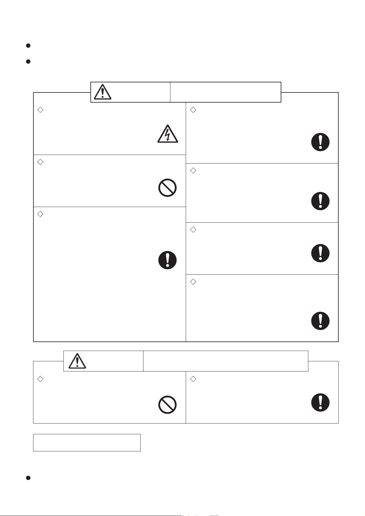
1. Safety precautions
Warning
Caution
Caution against
electric shock
Be sure to follow
this instruction.
Be sure to follow
this instruction.
Be sure to follow
this instruction.
Be sure to follow
this instruction.
Be sure to follow
this instruction.
Be sure to follow
this instruction.
Read the following precautions thoroughly before the maintenance, and then inspect and repair the product in a
safe manner.
The types and levels of danger that may arise if the product is handled incorrectly are described with the warning
symbols shown below.
Improper handling of the product may
result in serious injury or death.
Electric shock
If you must inspect the circuitry while the power is
on, do not touch the live parts.
(Failure to observe this warning may
result in electric shock.)
Modification is prohibited
Do not modify the unit.
(
Failure to observe this warning may
result in electric shock, fire and/or injury.
)
Prohibited
Proper electric work
Use the electric wires designated for electric work,
and conduct electric work in accordance with your
local electric work regulations and the installation
manual.
(Improper connection or wiring installation
may result in electric shock and/or fire.)
Turn off the power supply
Be sure to unplug the power cord, or shut off the
circuit breaker before disassembling the unit for
repair.
(Failure to observe this warning may
result in electric shock.)
Use proper parts and tools
For repair, be sure to use the parts listed in the parts
catalog of the applicable model and use the proper
tools.
(Failure to observe this warning may
result in electric shock, fire and/or injury.)
Replace damaged and/or degraded parts
Be sure to replace the power cord and lead wires if
they are damaged and/or degraded.
(Failure to observe this warning may
result in electric shock and/or fire.)
Check insulation
Upon completing repair work, always measure the
insulation resistance. Verify that it is at least 10 MΩ
(with a 500 V DC insulation resistance tester), and
then turn on the power.
(Inadequate insulation may result in
electric shock.)
Improper handling of the product may result in slight injury
or damage to properties including buildings and equipment.
Caution for injury
Do not work at a location where you do not have a
Wear gloves
Wear a pair of gloves when servicing.
sure footing.
(Failure to observe this caution may
(
Failure to observe this caution may result
in a fall.
)
Prohibited
result in injury to your hands from sharp
metal or other edges.)
Notes for servicing
●
Make sure that an earth leakage breaker and an overload protection device are installed, if they are not installed, recommend the customer to install one.
Make sure that the product operates properly upon completion of repair. Clean the product and the surrounding
area, and then notify the customer of the completion of repair.
─ 3 ─
Page 4
Precautions for soldering
Lead-free solder is used for the circuit boards of this product, and " " is marked on the circuit boards.
Observe the following precautions.
● When making repairs on these circuit boards, lead-free solder must be used.
● Make sure to use dedicated soldering irons to lead-free solder. (Do not use soldering irons that are used for
Sn-Pb [tin-lead] eutectic solder)
● It is recommended to use soldering irons having power consumption of 40 W or more.
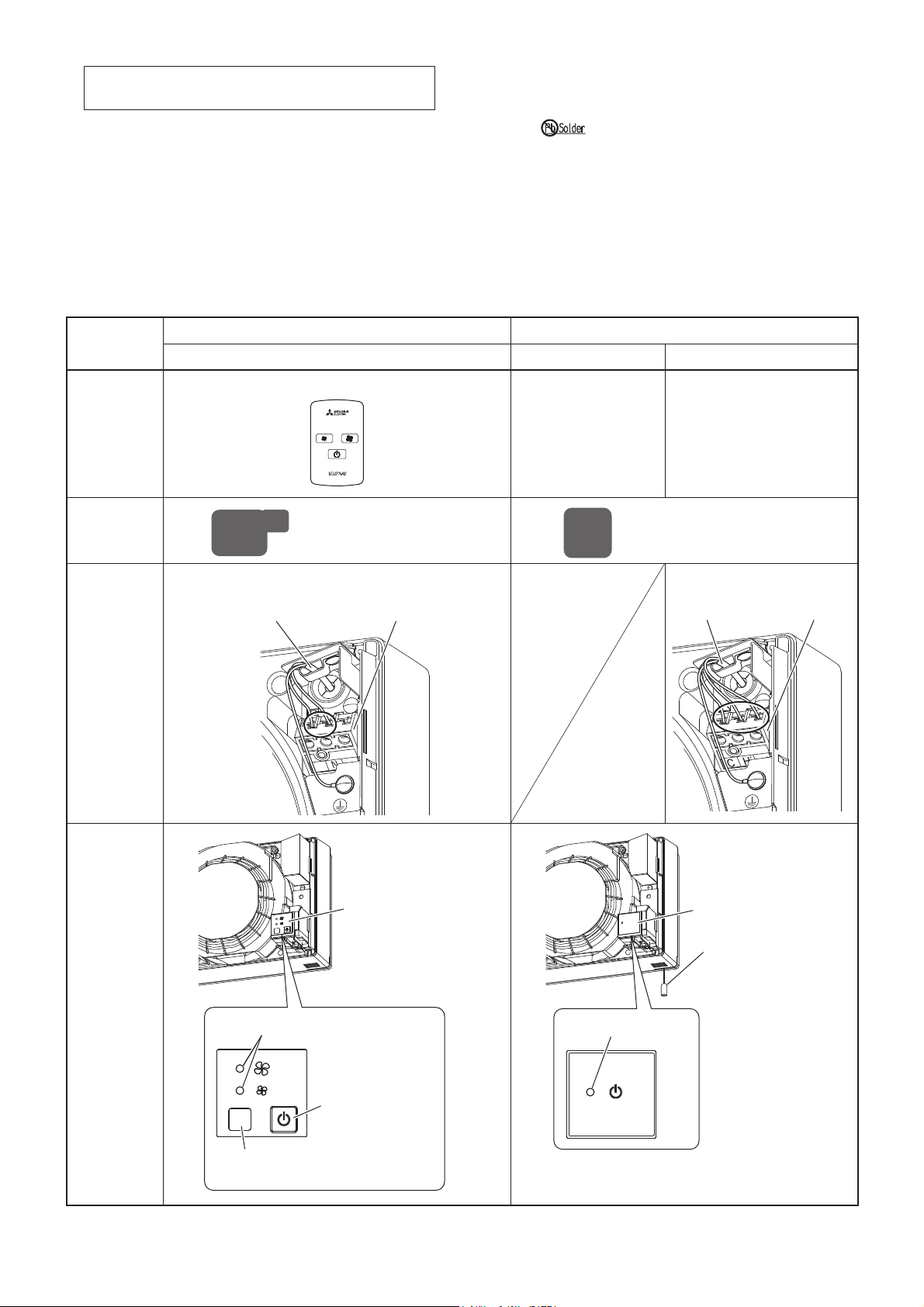
2. Changed points
Item
Operation
means
Shape of
main circuit
board
Wiring for
terminal
block
New model Previous model
VL-50SR2-E VL-50S2-E VL-50ES2-E
Remote controller
Pull cord switch
80x129 mm 80x80 mm
Two wires Three wires
Terminal blockPower cable
L
Control switch
(Wall switch)
Terminal blockPower cable
Display
Operation lamp
Operating mode
selection switch
Remote controller
receiver
Display
─ 4 ─
Operation lamp
Display
Pull cord
(VL-50S
2-E only)
Page 5
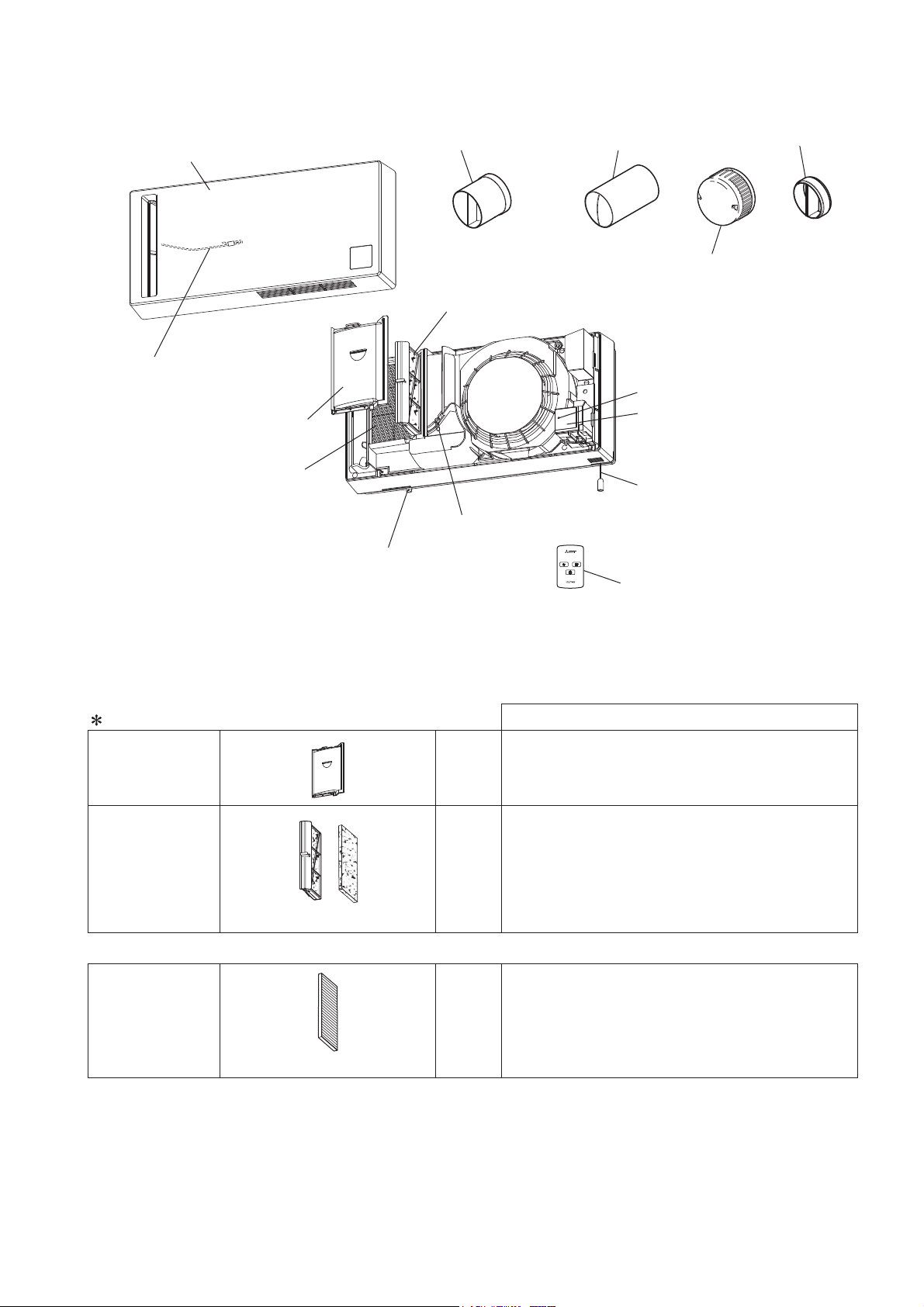
3. Names and functions of components
Panel
<Front panel>
Wire (fall prevention)
Exhaust air filter
<Filter>
Lossnay Core
(Heat exchanger)
Vertical mounting joint C
<Joint pipe>
Outside air filter
<Filter>
Hook
Shutter knob
Air supply/exhaust pipes A
<Pipe> (2 pcs.)
Weather cover
Operation lamp
Display
(Remove the provided
protective sheet.)
Pull cord
<Switch>
(VL-50S
2-E only)
Joint pipe B
<Joint pipe>
Note:
The names in the angle brackets < >
show the part names in the parts catalog.
About the filters
For
Exhaust air filter
Outside air filter
(Replacement filter: P-50F2-E)
Outside air filter can be replaced with the following high performance filter.
High performance
filter
(Optional parts)
(P-50HF2-E)
Exhaust
For
Supply
For
Supply
The filter prevents clogging of the internal components.
air
When Lossnay takes in outside air to a room, the
filter collects dust, sand, pollen or the likes from
outside air.
Note: Some fine particles or tiny insects may pass
air
air
through the filter. The high performance filter
is recommended for higher collecting effect.
The filter collects dust more efficiently than the
outside air filter.
Remote controller
(VL-50SR
2-E only)
Features
─ 5 ─
Page 6
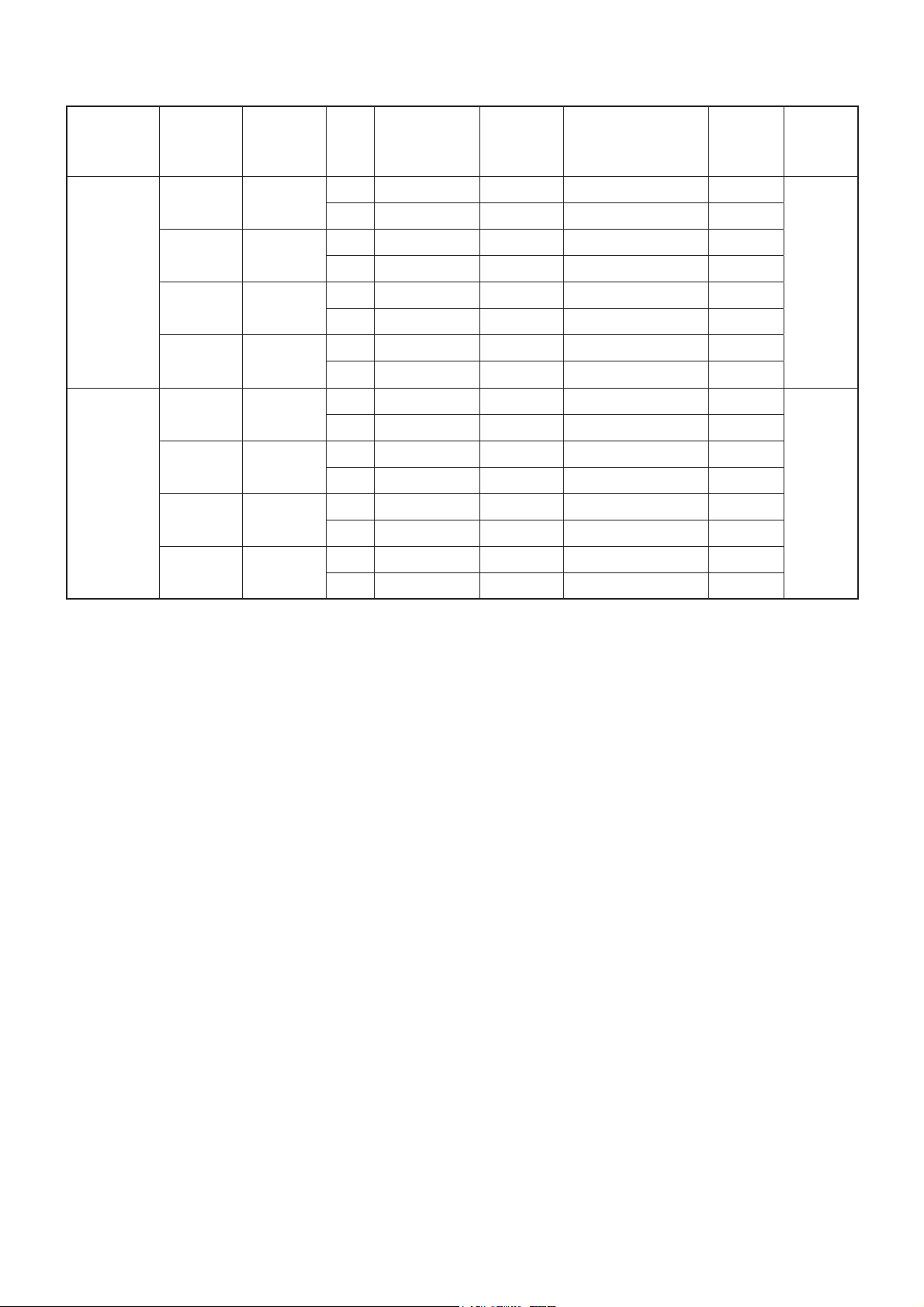
4. Specifications
Model
VL-50S
VL-50ES2-E
VL-50SR
2-E
2-E
Supply
voltage (V)
220 50
230 50
240 50
220 60
220 50
230 50
240 50
220 60
Frequency
(Hz)
Power
Notch
consumption
(W)
HI 19 51 70 36.5
LO 4 15 86 14
HI 20 52.5 69 37
LO 4.5 16 85 15
HI 21 54 68 37.5
LO 5 17 84 15.5
HI 21 54 68 37.5
LO 5.5 17 84 15.5
HI 19 51 70 36.5
LO 4.5 15 86 14
HI 20 52.5 69 37
LO 5 16 85 15
HI 21 54 68 37.5
LO 5.5 17 84 15.5
HI 21 54 68 37.5
LO 6 17 84 15.5
Air volume
3
/h)
(m
Temperature
exchange efficiency
(%)
Noise
(dB)
Weight
(kg)
6.2
6.2
* Noise values may be higher than those listed depending on the structure of the room.
─ 6 ─
Page 7
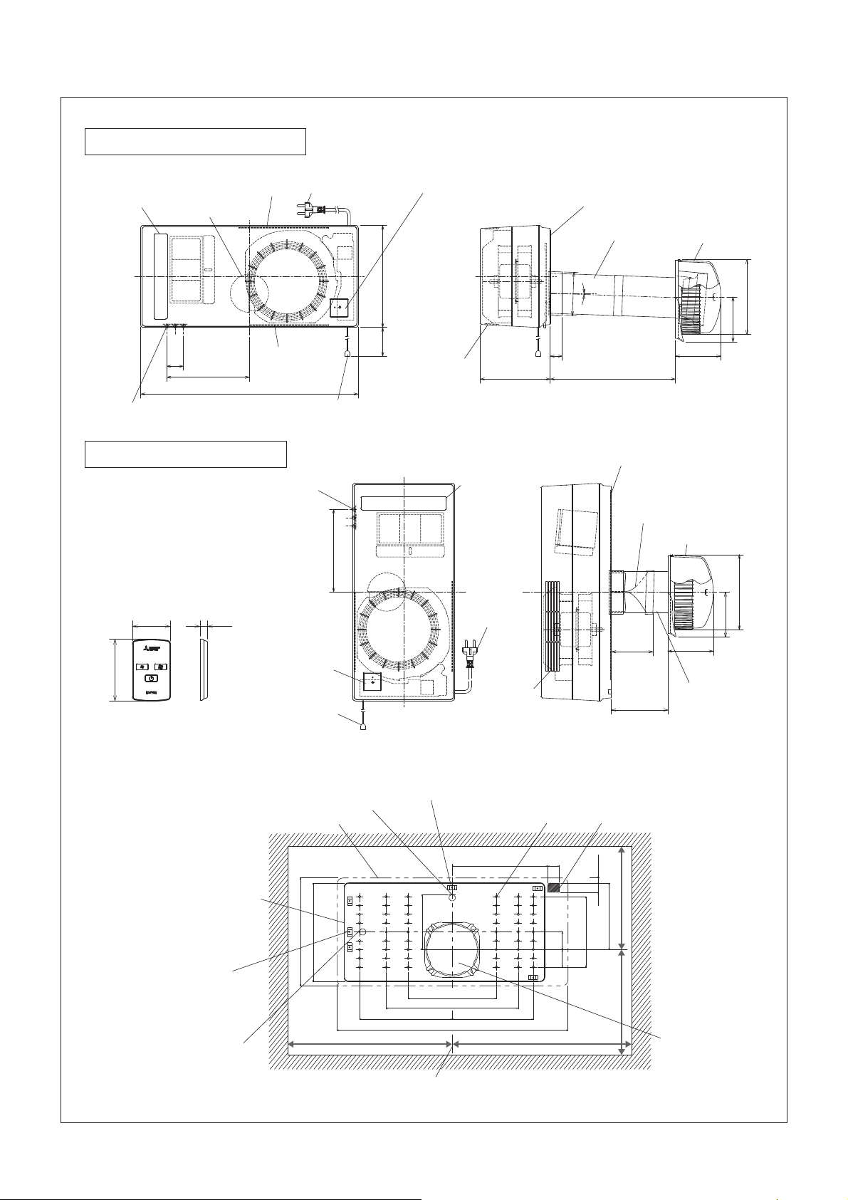
5. Outside dimensions
VL-50S2-E, VL-50ES2-E, VL-50SR2-E
For horizontal mounting
Indoor air
Air supply
hole
Shutter knob
Air supply/
exhaust hole
40
exhaust hole
198.5
522
For vertical mounting
* For vertical mounting, the
display comes to the lower
side. (The unit cannot be
mounted upside down.)
Ŷ Remote controller
(VL-50SR2-E only)
1054
Indoor air
exhaust hole
Shutter
knob
Power cable
(VL-50S
Pull cord
(VL-50S
198.5
2-E only)
2-E only)
245
About
400
Display
(The figure shows
VL-50S
Indoor air
exhaust hole
2-E/VL-50ES2-E.)
Air supply
hole
Power cable
(VL-50S2-E only)
168
Mounting plate
Air supply/exhaust
pipe
114
°
φ
2
28
Wall thickness
50 to 650
Mounting plate
Attach the twisted part of
the vertical mounting joint C
toward the indoor side.
Weather cover
108
109
Weather cover
180
φ
108
180
φ
88
Pull cord
(VL-50S2-E only)
Display
Indoor air
exhaust hole
Ŷ Mounting position diagram (seen from inside)
Mounting plate temporary
fixing hole position (For horizontal mounting)
Edge of main unit Mounting hole 53 – ø6
Mounting plate
245
223.5
Unit hanging screw
position
(For vertical mounting)
Mounting plate
temporary fixing hole
position
(For vertical mounting)
Unit hanging screw position
(For horizontal mounting)
125
200
210.5
min. min.
310 360
Center line
300
522
216
184
26.5
96.5
Wall
thickness
120 to 730
Power and connection
cable pullout area
(VL-50ES
11.5
21
2-E only)
min.
193
151.5
40.539.5
20×8=160
min.
182
109
Air supply/exhaust
pipe
Air supply/exhaust
hole
(ø120 wall hole)
─ 7 ─
Unit (mm)
Page 8
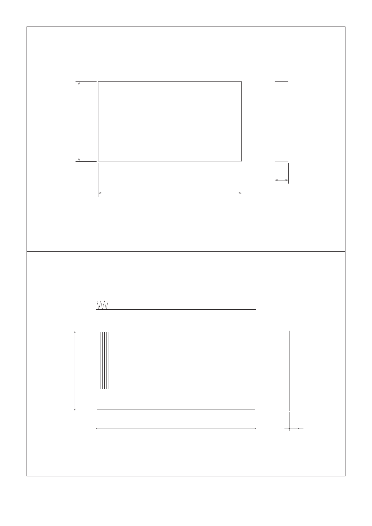
P-50F2-E
76
13
154
P-50HF
2-E
76
153
Unit (mm)
8
─ 8 ─
Unit (mm)
Page 9
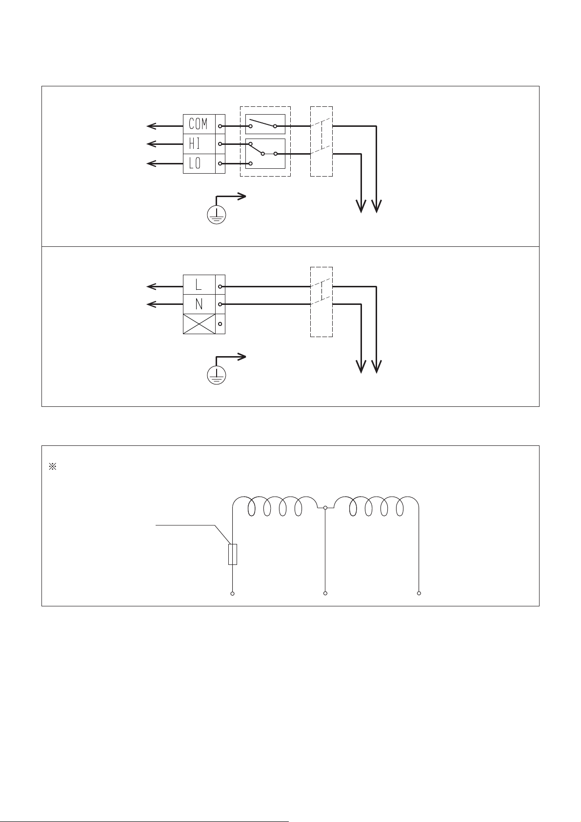
6. Electrical wiring diagrams
(1) Switch wiring diagrams
VL-50ES2-E
Red
White
Blue
Terminal block Switch Circuit breaker
220/230/240 VAC 50 Hz
220 VAC 60 Hz
VL-50SR
2-E
Red
White
Terminal block Circuit breaker
(2) Motor coil diagram
VL-50S2-E, VL-50ES2-E, VL-50SR2-E
Coil resistance at a temperature of 30°C
Thermal fuse
145Υ
220/230/240 VAC 50 Hz
220 VAC 60 Hz
0FRLOȍ6FRLOȍ
White
─ 9 ─
Black
Red
Page 10

7. Circuit board diagrams
Circuit board diagrams and check points
(1) VL-50S
AC power supply input
220/230/240 VAC 50 Hz
220 VAC 60 Hz
White connector
Phase advance capacitor
White connector
2-E (Pull cord type)
Power cord
Motor
White connector
2 ȝF
Operation lamp
(green)
Not in use
<Display circuit board>
VL-35-B
Voltage-dividing capacitor
<Main circuit board>
VL-35-A
Blue
White
Red
ȝ)ȝ)
White connector
Switch with a pull cord
(2) VL-50ES2-E (Wall switch type)
AC power supply input
220/230/240 VAC 50 Hz
220 VAC 60 Hz
Control switch
Terminal block
Not in use
Motor
White connector
Phase advance capacitor
2 ȝF
White connector
<Display circuit board>
Red
Operation lamp
(green)
VL-35-B
Voltage-dividing capacitor
ȝ)ȝ)
White connector
Blue
White
<Main circuit board>
VL-35-A
─ 10 ─
Not in use
Page 11
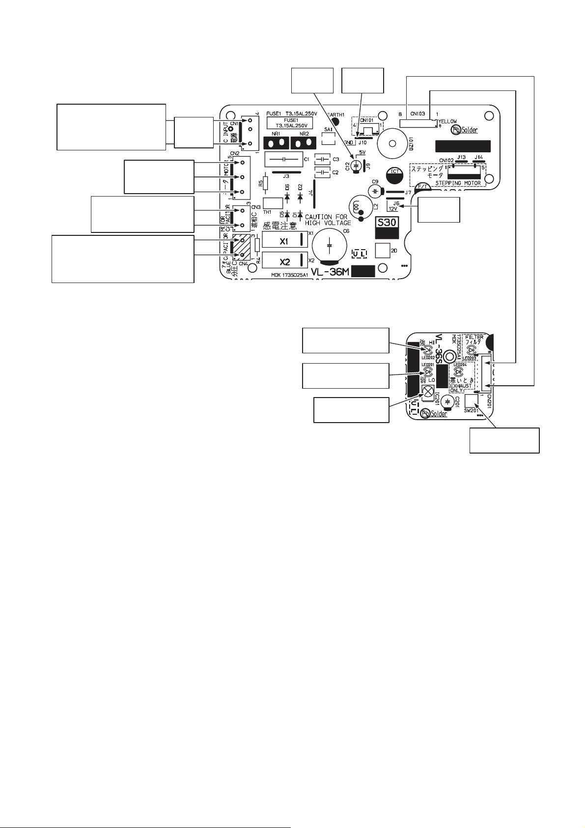
(3) VL-50SR2-E (Remote controller type)
AC power supply input
220/230/240 VAC 50 Hz
220 VAC 60 Hz
White connector
White connector
Phase advance capacitor
2 ȝF
White connector
Voltage-dividing capacitor
ȝ)
(1ȝF and 2ȝF capacitors in series)
Blue connector
Motor
Terminal
block
5 V DC
(C12 (+))
<Main circuit board>
VL-36M
GND
(J10)
12 V DC
(J6)
<Display circuit board>
VL-36S
High operation lamp
(Green)
Low operation lamp
(Green)
Remote control
signal receiver IC
Operating mode
selection switch
─ 11 ─
Page 12
8. Principles of operation
(1) VL-50S2-E (Pull cord type)
• Operating mode (fan speed) can be switched from HI (High) to LO (Low) to OFF by using the switch with a
pull cord.
<Lighting status of the operation lamp under each operating mode>
Operating mode of the fan OFF HI LO
Operation lamp (LED1) Off Lit Lit
(2) VL-50ES2-E (Wall switch type)
• Operating mode (fan speed) can be switched by using the control switch. Operations may vary depending
on the switches installed.
220/230/240 V is applied between HI and COM2
220/230/240 V is applied between LO and COM2
<Lighting status of the operation lamp under each operating mode>
Operating mode of the fan OFF HI LO
Operation lamp (LED1) Off Lit Lit
HI (High)
LO (Low)
(3) VL-50SR2-E (Remote controller type)
• Operating mode (fan speed) can be selected from HI (High), LO (Low), and Power ON/OFF by using the
remote controller.
• Operating mode (fan speed) can be switched from HI (High) to LO (Low) to OFF by using the operating
mode selection switch on the main unit.
<Lighting status of the operation lamps under each operating mode>
Operating mode of the fan OFF HI LO
Operation lamp (LED201) Off Off Lit
Operation lamp (LED202) Off Lit Off
─ 12 ─
Page 13
9. Troubleshooting
Work precautions
• When servicing, be sure to recreate the malfunction two or three times before starting repairs.
• When servicing, always take care to keep proper footing.
• Before starting the service, always unplug the power cord from the outlet, or turn off the circuit breaker
when no power cord plug is provided. Sufficient care must be taken to avoid electric shock or injury.
• Make sure to connect the power supply wires correctly.
• When removing the circuit board, always hold it at both ends and remove carefully so as not to apply force
to the surface mounted parts.
• When removing the circuit board, be careful of the metal edges on the board.
• When removing or inserting the connectors for the circuit board, hold the entire housing section. Never pull
on the lead wires.
• When circuit board failure is considered to be a cause, check closely for any broken section on the copper
foil patterns, burning or discoloration of parts.
• After replacing a circuit board, make sure to restore the same settings as before the replacement.
The part names in the text are standardized with the part names in the parts catalog. (There are some
exceptions.)
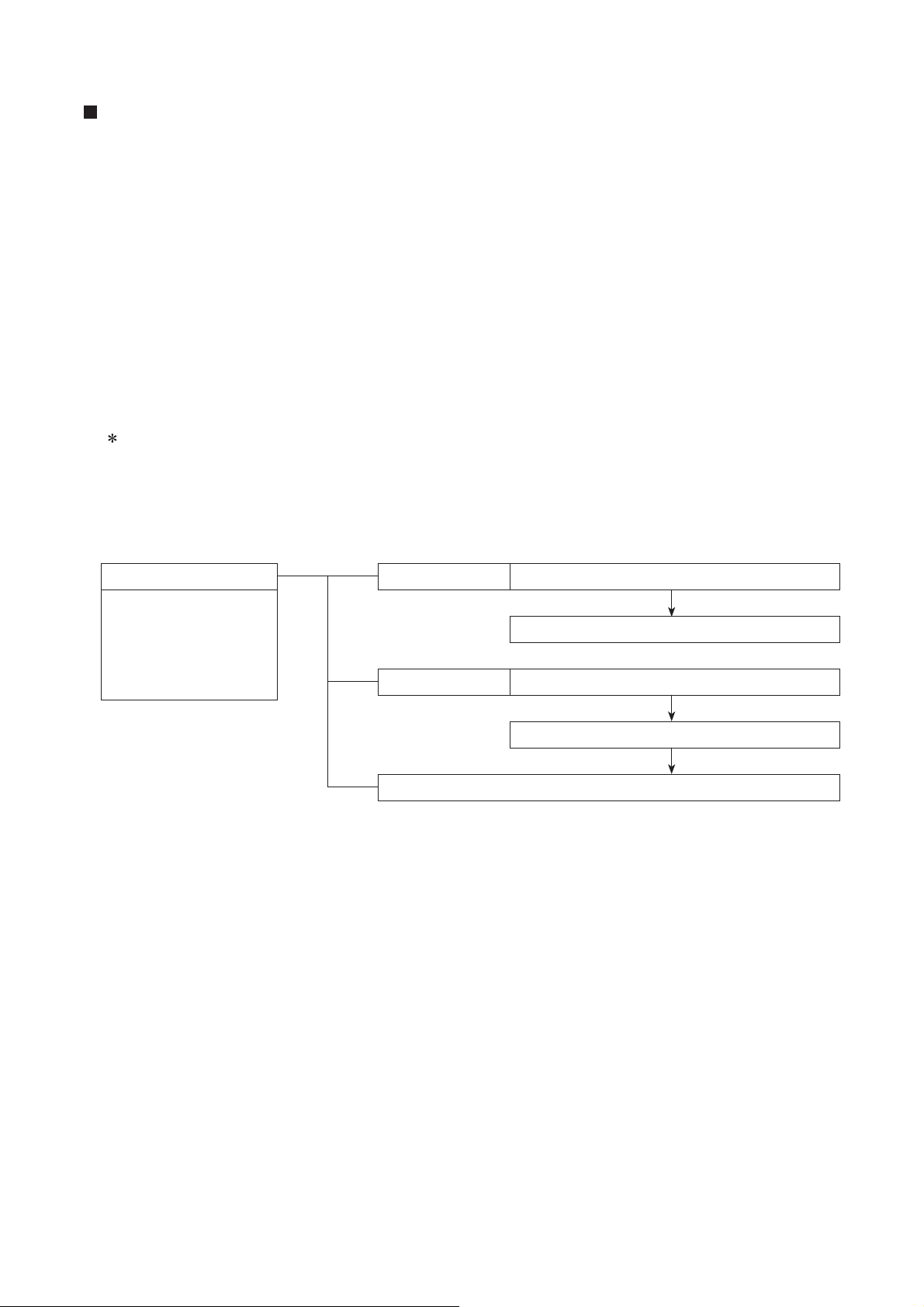
(1) Service Flowchart
After checking the preliminary check items below, follow troubleshooting 1 and 2 for servicing.
Preliminary check items
1. Condition of trouble
2. Frequency of trouble:
The date of starting
operation and occurrence of trouble
Troubleshooting 1 Lossnay does not operate, or it stops by itself.
Check (2) Initialization checklist.
Troubleshooting 2 Lossnay operates abnormally.
Check (3) Lossnay checklist.
Check "10. Before receiving repair requests."
─ 13 ─
Page 14
(2) Initialization checklist
Troubleshooting 1 Lossnay does not operate, or it stops by itself.
No.
Error Cause Action
1 Lossnay does
not operate.
<VL-50S
• Is the power plug connected to the
power source of the rated voltage?
<VL-50ES2-E, VL-50SR2-E>
2-E>
Supply the rated voltage 220/230/240 VAC.
If a power failure has occurred, wait for power
failure recovery.
• Is the rated voltage 220/230/240 VAC
supplied to the terminal block?
<VL-50ES
2-E, VL-50SR2-E>
Are there any poor connections of the
Check that the circuit breaker is ON.
Connect the lead wires securely.
terminal block?
<VL-50S
Is the following power supply connec-
2-E, VL-50SR2-E>
Connect the connector securely.
tor on the main circuit board securely
connected?
VL-50S2-E: CN2
VL-50SR2-E: CN1
Is the current fuse on the main circuit
board blown?
If the current fuse is blown, determine the
cause of the failure (abnormal voltage applica-
tion or wrong connection), and eliminate the
cause. Then, replace the main circuit board
together with the display circuit board.
Are there any problems with the main
circuit board or display circuit board?
Diagnose the problems of the circuit boards
by checking the Basic checklist for the major
components (Table 1). (See page 16.)
<VL-50S
Is the power cord properly plugged into
2-E>
Plug the power cord properly.
the wall outlet?
<VL-50S
Is the switch with a pull cord turned
2-E>
Turn ON the switch with a pull cord.
ON?
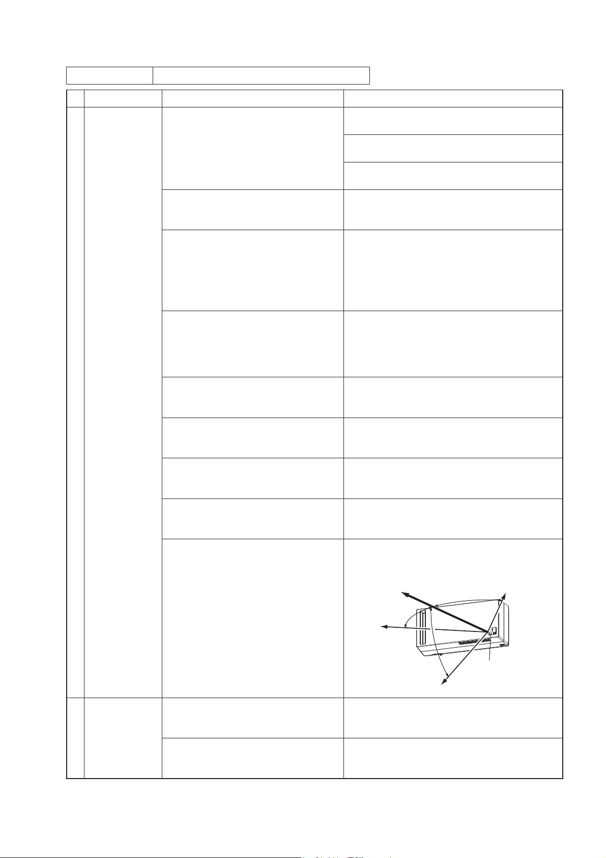
<VL-50SR
2-E>
Is the battery exhausted? Replace it with a commercially available lithium
battery (CR2025).
<VL-50SR
• Is the remote controller operated at
the position too far away from the
main unit?
• Is the remote controller case installed
outside the remote control signal
receiving range?
2-E>
The remote control signal receiving range is
shown below.
Front: 4 m
Left: 3 m
45°
45°
Right: 3 m
2 Lossnay stops
by itself.
<VL-50ES2-E, VL-50SR2-E>
Are there any poor connections of the
terminal block?
Are there any problems with the main
circuit board or display circuit board?
─ 14 ─
45°
Downward: 3 m
Receiver
Connect the lead wires securely.
Diagnose the problems of the circuit boards
by checking the Basic checklist for the major
components (Table 1). (See page 16.)
Page 15

(3) Lossnay checklist
Troubleshooting 2 Lossnay operates abnormally.
No.
Error Cause Action
1 The shutters
do not open or
close.
2 The fans do not
rotate.
3 The fans do not
stop.
4 Operating mode
(fan speed) cannot be switched.
5 An unusual
noise comes
from the fans.
6 The operation
lamp does not
illuminate.
Is there any foreign matter or obstruction
Remove it.
around the shutters?
Are the shutters detached from guide rails
Attach the shutters properly.
of the casing?
Are the following connectors on the main
Connect the connectors securely.
circuit board securely connected ?
VL-50S2-E, VL-50ES2-E: CN3, CN4, CN5
VL-50SR2-E: CN2, CN3, CN4
Do the fan blades touch other components?
Is there any foreign matter around the fans?
Check for any abnormal area.
Replace any abnormal or defective parts.
Remove it.
Are there any problems with the motor? Diagnose the problems of the motor by
checking the Basic checklist for the major
components (Table 1). (See page 16.)
Is the voltage 220/230/240 V AC output
from the main circuit board?
Disconnect the following motor connector to
check the output voltage.
VL-50S
2-E, VL-50ES2-E: CN3
VL-50SR2-E: CN2
(See page 16.)
<VL-50S
Do the fans continue operating even if the
switch with a pull cord is turned OFF?
<VL-50S
Is the switch with a pull cord caught on
2-E>
If the fans do not stop operating, replace the
switch.
2-E>
Eliminate the cause of catching.
some components?
<VL-50S
Does the switch with a pull cord work
properly?
2-E>
Operate the switch to check whether it ob-
tains click feeling. If there are any prob-
lems, replace the switch.
Are there any problems with the main
circuit board or display circuit board?
Diagnose the problems of the circuit boards
by checking the Basic checklist for the major
components (Table 1). (See page 16.)
Is there any foreign matter around the fans?
Are there any odd feelings when rotating
the fan?
Does the motor generate abnormal
noise?
Remove it.
If there are any odd feelings, replace the
motor.
Diagnose the problems of the motor by
checking the Basic checklist for the major
components (Table 1). (See page 16.)
Are the Lossnay core and filters properly
Install the Lossnay core and filters properly.
installed? (Check the installation directions and positions.)
Is the LED on the display circuit board
tilted?
Is the following connector on the display
Attach the LED case cover so that the LED is
positioned in the hole of the LED case cover.
Connect the connector securely.
circuit board securely connected?
VL-50S
VL-50SR
Are there any problems with the main
circuit board or display circuit board?
2-E, VL-50ES2-E: CN1
2-E: CN201
Diagnose the problems of the circuit boards
by checking the Basic checklist for the major
components (Table 1). (See page 16.)
─ 15 ─
Page 16

No.
7 The front
8 Cold air or wind
Error Cause Action
Are the Lossnay core and filters properly
panel cannot be
closed.
installed? (Check the installation directions and positions.)
Are the shutters being kept open when
comes into the
the fans are stopped?
room.
Basic checklist for the major components (Table 1)
No.
Components Judging instructions
1 Motor Check the coil resistance.
Disconnect the following connector from the main circuit board, and then measure
the resistance between the motor lead wires.
VL-50S
2-E, VL-50ES2-E: CN3
VL-50SR2-E: CN2
See Chapter 6. (2) Motor coil diagram (page 9) for the resistance values.
In the case of an open circuit or short circuit, replace the motor.
2 Switch with a pull
cord
(VL-50S
2-E only)
Remove the switch from the main unit. Measure the resistance at the weld for the
wire connection on the backside of the switch.
If the resistance differs from the values listed below, replace the switch.
Install the Lossnay core and filters properly.
Move the shutter knob to the CLOSE posi-
tion.
Color of wires
Red - White High
Red - Blue Low
3 Display circuit
board
[1] Check the appearance.
• Check whether the circuit name is proper.
VL-50S2-E, VL-50ES2-E: VL-35-B
VL-50SR2-E: VL-36S
• Check if any parts are damaged.
• Check if any parts are stained with sticking liquid or the like.
• Check if the solder is cracked.
• Check if the circuit board is cracked.
[2] Check the operating mode selection switch (VL-50SR
• Are the connectors CN201 on the display circuit board and CN103 on the main
circuit board securely connected?
• If the operating mode selection switch does not work, even though the remote controller is operable, replace the display circuit board together with the main circuit
board.
If any of the above items is not satisfied, replace the display circuit board together
with the main circuit board.
4 Main circuit board [1] Check the appearance.
• Check whether the circuit name is proper.
VL-50S
2-E, VL-50ES2-E: VL-35-A
VL-50SR2-E: VL-36M
• Check if any parts are damaged.
• Check if any parts are stained with sticking liquid or the like.
• Check if the solder is cracked.
• Check if the circuit board is cracked.
• Check if the varistors NR1 and NR2 are damaged.
( If they are damaged, it is due to application of an abnormal voltage. (Wrong instal-
lation work))
Operating mode
(fan speed)
Resistance
Short-circuited
2-E only)
─ 16 ─
Page 17

No.
Components Judging instructions
4 Main circuit board [2] Check the motor drive.
• Motor: Measure the voltage between the pins of the following connector.
VL-50S
VL-50SR
2-E, VL-50ES2-E: CN3
2-E: CN2
At high fan speed output: Between 1 and 5 pins: 220/230/240 V AC ± 5 V
At low fan speed output: Between 1 and 5 pins: 80 V AC or more
For details of the above checkpoints, see Chapter 7. Circuit board diagrams.
If any of the above items is not satisfied, replace the main circuit board together with
the display circuit board.
5 Remote controller
(VL-50SR
2-E only)
• Check if the battery is old. (Battery voltage 2.9 V or more is required.)
• If the remote controller does not work, even though the operating mode selection
switch is operable, the remote controller might be broken.
( Take a digital photo of the transmitter part on the remote controller to check
whether infrared rays are emitted from the remote controller.)
10. Before receiving repair requests
Frequently asked question Response
The incoming air feels cold. Has the outside air temperature dropped?
If the outside air temperature has dropped, switch the operating mode to
"Exhaust only mode," or stop the operation and close the shutters.
When switching the operating
mode or adjusting the shutter knob,
there is a noise inside the product.
The product does not operate. [1]
The operation sound becomes
louder.
The air volume is low. If the filters are clogged, clean them in accordance with the operating
No air is coming from the product.
Not much air is coming from the
product.
The front panel cannot be closed. If Lossnay core and filters are not properly installed, reinstall them prop-
When adjusting the shutter knob,
there is a noise inside the product.
Cold air or wind comes in more
than usual when the product is
stopped.
Operation sensitivity of the remote controller is low.
(VL-50SR
2-E only)
This sound is the operation sound of the motor or shutters in the product.
It is not a malfunction.
The power plug is almost detached from the wall outlet. (VL-50S2-E only)
[2] The circuit breaker on the distribution board is OFF.
[3] A power failure has occurred.
[1] If the front panel or the filters are almost detached (or tilted), reinstall
them properly.
[2] If the shutters are closed, adjust the shutter knob to the OPEN position.
[3] If the filters are clogged, clean them in accordance with the operating
instructions.
instructions.
If the shutters are closed, adjust the shutter knob to the OPEN position.
erly. (For example, a component is out of position or inserted backwards.)
This sound is the operation sound of the shutters in the product. It is not a
malfunction.
If the shutters are being kept open, adjust the shutter knob to the CLOSE
position.
[1] Check if the battery is weak. (Replace it with a commercially available
lithium battery (CR2025).)
[2] Check if the remote controller is operated at the position too far away
from the product, or at the improper angle. (See page 14.)
Operation sensitivity of the infrared remote controller can be affected by
[3]
strong light such as sunlight or room illumination. It is not a malfunction.
[4] Electromagnetic waves can affect the operation sensitivity at the loca-
tions in close proximity of electronic devices such as a television. It is
not a malfunction.
─ 17 ─
Page 18

11. Service inspection list
Front panel
Hook
Wire
Front panel
Wire
Hook
Front panel
Front panel
Location Inspection Item Check Result
Electric
wiring
Are the power lead wires securely connected to the terminal block?
(VL-50ES
Is the wiring correct?
Is the product securely mounted?
Does Lossnay operate as described in the operating Instructions when operating the switch?
2-E and VL-50SR2-E only)
Appliance
Is the fan rotating?
Are the connectors securely connected?
Do the shutters work?
Does Lossnay operate without abnormal vibration or noise?
12. Overhauling procedures
Work precautions
• Before replacing parts, follow the instructions described in the troubleshooting.
• When servicing, always keep proper footing.
• When servicing, always unplug the power cord from the outlet, or turn off the circuit breaker. Pay sufficient
attention to avoid electric shock or injury.
• Always connect the power wires properly.
• Pay attention not to drop the parts or components.
• After completing repairs, check that the product operates properly.
Always wear a pair of gloves when servicing.
The part names in the text are standardized with the part names in the parts catalog. (There are some exceptions.)
12-1 VL-50S2-E, VL-50ES2-E
(1) Turn off the power.
[1] Stop the operation by turning off the switch.
[2] Turn off the circuit breaker on the distribution board, or unplug the power cord.
(2) Remove the front panel.
[1] Hold both ends of the front panel, and pull it forward.
[2] Suspend the detached front panel by using the wire.
Precautions
• When removing the front panel from the main unit, hold the hook to disengage the wire.
• Do not shake the suspended front panel. (The wallpaper could be damaged.)
<When the unit is installed vertically><When the unit is installed horizontally>
─ 18 ─
Page 19

Terminal block
Bush
Ground cable
Ground screw
Cord clamp
Lead-in opening
Power cable
Mounting
plate
Main unit
PCB case cover
(3) Dismount the main unit.
For VL-50ES2-E
[1] Remove the PCB case cover.
Unscrew the screws (one PTT screw 4×8, indicated by
Reassembly precaution
Tightening torque for the screws: 1.1 N.m
[2] Disconnect the power cable and ground cable
from the main unit.
, and one PP screw 3×8, indicated by ).
For both models
[3] Unscrew the screws (four special screws 4x10.5,
indicated by ), and dismount the main unit.
Precaution
Pay attention to unhook the main unit from the
unit fixing screw (one special screw 4x10.5, indicated by
) on the mounting plate.
Reassembly precaution
Tightening torque for the screws: 1.1 N.m
* The figure shows VL-50ES2-E.
─ 19 ─
Page 20

(4) Remove the display circuit board (VL-35-B).
[1] Unscrew the screw (one PTT screw 4x12, indi-
cated by
parts together with the LED case cover and LED
case.
Reassembly precaution
Tightening torque for the screw: 1.1 N.m
[2] Remove the LED case cover, and unscrew the
screw (one PPT screw 3x8, indicated by ).
Reassembly precaution
Tightening torque for the screw: 0.7 N.m
), and remove the display circuit board
LED case cover
LED case
[3] Disconnect the connector from the display circuit
board, and remove the circuit board (VL-35-B).
Reassembly precaution
Securely connect the connector to the display
circuit board.
ConnectorDisplay circuit board (VL-35-B)
─ 20 ─
Page 21

Insert
Fan side
Lossnay Core
Guide
Marking
Guide rail
Marking on the
Lossnay core
Exhaust air filter
Outside air filter
Filter frame
Tab
Outside air filter
bb
aa
Tab
Press
Lossnay Core
(5) Remove the Lossnay core and filters.
[1] Remove the exhaust air filter from the main unit.
a. Hold the filter as shown in the figure.
b. Unhook the top part of the filter, and pull for-
ward to remove it.
[2] Hold the knob of the outside air filter to pull it out,
and remove it from the main unit.
[3] Remove the outside air filter from the filter frame.
a. Press the tabs (two locations) to open the filter
frame.
b. Remove the outside air filter.
[4] Pull out the Lossnay core.
Reassembly precautions
• When installing the Lossnay core, pay attention
not to curl the packing.
• Deeply insert the Lossnay core.
• Reinstall the Lossnay core as before.
* To install the Lossnay core in the correct direc-
tion, check the marking on the Lossnay core:
Insert" and " Fan side."
"
* Insert the guide of the Lossnay core into the
guide rails of the main unit.
─ 21 ─
Page 22

PCB cover
PCB case
(6) Remove the fan guard and fan casing (front).
[1] Unscrew the screws (three PTT screws 4x25,
indicated by
), and remove the fan guard.
Reassembly precaution
Tightening torque for the screws: 1.1 N.m
[2] Unscrew the screws (two PTT screws 4x14, indi-
cated by ), and remove the fan casing (front).
Reassembly precautions
• When attaching or removing the fan casing
(front), make sure to prevent it from contacting
with the part of the PCB box indicated by
.
• Tightening torque for the screws: 1.1 N.m
Reassembly precaution
When attaching the fan casing (front), fit its hole
onto the damper shaft that is assembled on the
fan casing.
Fan casing (front)
Fan casing (front)
Hole of the fan
casing (front)
Damper shaft
PCB box
Fan guard
(7) Remove the main circuit board (VL-35-A).
[1] Disengage the PCB box from the hook parts of
the casing (two locations, indicated by ).
[2] Unscrew the screw (one PT screw 4x8, indicated
), and remove the PCB cover.
by
Reassembly precaution
Tightening torque for the screw: 1.1 N.m
Damper
PCB box
─ 22 ─
* The figure shows VL-50S
2-E.
Page 23

[3] Remove the rivets (four pieces, indicated by ),
and remove the main circuit board (VL-35-A).
Reassembly precautions
• Fasten the motor lead tube, ground wire for the
motor, and power cord with the lead wire clip.
• Make sure that the lead wires for the display
circuit board come out from the cutout of the
PCB case (indicated by
).
Motor lead tube
Ground wire
for the motor
Power cord
Lead wire clip
PCB case
For VL-50S2-E
Reassembly precaution
The pull cord for the switch must be drawn out
to the left side of the spacer as shown in the
picture.
(8) Remove the centrifugal fans and motor.
[1] Remove the damper.
Main circuit board
(VL-35-A)
* The figure shows VL-50S
Lead wires for the
display circuit board
Pull cord
2-E.
Spacer
[2] Unscrew the clamping screw for the motor fix
plate (one PTT screw 4x12, indicated by
).
Reassembly precaution
Tightening torque for the screw: 1.1 N.m
─ 23 ─
Damper
Motor fix plate
Page 24

Centrifugal fan
(Air exhaust fan)
Centrifugal fan
(Air supply fan)
Motor
Lead cover
White
Black
Shutter (for supply air)
Casing
Shutter (for exhaust air)
Reassembly precautions
• Attach the damper to the fan casing so that the damper shaft is not tilted.
•
Insert the protrusion of the damper shaft (indicated by ) into the hole of the fan casing (front). (See page 22.)
Damper
[3] Remove the special nut (M8) and tab washer (one
each, indicated by ), and remove the centrifugal fan together with the special washer (8) (one
each, indicated by ).
Reassembly precaution
Tightening torque for the nut: 2.0 N.m
[4] Unscrew the screws (two PTT screws 4x10, indi-
cated by ), and remove the lead cover.
Reassembly precautions
• Insert the lead cover
under the motor when
attaching it. (Indicated by
)
• Tightening torque for the screws: 1.6 N.m
[5] Unscrew the screws (four PTT screws 4x10, indi-
cated by
Reassembly precaution
Tightening torque for the screws: 1.6 N.m
), and remove the motor.
Lead cover
Fan casing
Damper
(9) Remove the shutters.
• Remove the shutters (for supply/exhaust air) from
the casing.
Reassembly precautions
• Make sure that the shutter (for exhaust air) is
securely hooked on the claws and hollows of
the casing. (Three locations, indicated by
• Make sure that the shutter (for supply air) is securely hooked on the claws and protrusions of
the casing and shutter (for exhaust air). (Three
locations, indicated by )
When reassembling
Reassemble the unit in the reverse order of disassembly.
After reassembly, always make a test run to make
sure that the unit operates properly.
)
─ 24 ─
Page 25

12-2 VL-50SR2-E
Front panel
Hook
Wire
Front panel
Wire
Hook
Front panel
Front panel
Terminal block
Bush
Ground cable
Ground screw
Cord clamp
Lead-in opening
Power cable
PCB case cover
(1) Turn off the power.
[1] Stop the operation.
[2] Turn off the circuit breaker on the distribution board.
(2) Remove the front panel.
[1] Hold both ends of the front panel, and pull it forward.
[2] Suspend the detached front panel by using the wire.
Precautions
• When removing the front panel from the main unit, hold the hook to disengage the wire.
• Do not shake the suspended front panel. (The wallpaper could be damaged.)
<When the unit is installed vertically><When the unit is installed horizontally>
(3) Dismount the main unit.
[1] Remove the PCB case cover.
Unscrew the screws (one PTT screw 4×8, indicated by , and one PP screw 3×8, indicated by ).
Reassembly precaution
Tightening torque for the screws: 1.1 N.m
[2] Disconnect the power cable and ground cable
from the main unit.
─ 25 ─
Page 26

Mounting
plate
Main unit
[3] Unscrew the screws (four special screws 4x10.5,
indicated by ), and dismount the main unit.
Precaution
Pay attention to unhook the main unit from the
unit fixing screw (one special screw 4x10.5, indicated by
Reassembly precaution
Tightening torque for the screws: 1.1 N.m
) on the mounting plate.
(4) Remove the display circuit board (VL-36S).
[1] Unscrew the screw (one PTT screw 4x12, indi-
cated by
parts together with the LED case cover and LED
case.
Reassembly precaution
Tightening torque for the screw: 1.1 N.m
[2] Remove the LED case cover, and unscrew the
screw (one PPT screw 3x8, indicated by ).
Reassembly precaution
Tightening torque for the screw: 0.7 N.m
), and remove the display circuit board
LED case cover
LED case
[3] Disconnect the connector from the display circuit
board, and remove the circuit board (VL-36S).
Reassembly precaution
Securely connect the connector to the display
circuit board.
─ 26 ─
ConnectorDisplay circuit board (VL-36S)
Page 27

Insert
Fan side
Lossnay Core
Guide
Marking
Guide rail
Marking on the
Lossnay core
Exhaust air filter
Outside air filter
Filter frame
Tab
Outside air filter
bb
aa
Tab
Press
Lossnay Core
(5) Remove the Lossnay core and filters.
[1] Remove the exhaust air filter from the main unit.
a. Hold the filter as shown in the figure.
b. Unhook the top part of the filter, and pull for-
ward to remove it.
[2] Hold the knob of the outside air filter to pull it out,
and remove it from the main unit.
[3] Remove the outside air filter from the filter frame.
a. Press the tabs (two locations) to open the filter
frame.
b. Remove the outside air filter.
[4] Pull out the Lossnay core.
Reassembly precautions
• When installing the Lossnay core, pay attention
not to curl the packing.
• Deeply insert the Lossnay core.
• Reinstall the Lossnay core as before.
* To install the Lossnay core in the correct direc-
tion, check the marking on the Lossnay core:
Insert" and " Fan side."
"
* Insert the guide of the Lossnay core into the
guide rails of the main unit.
─ 27 ─
Page 28

PCB cover
PCB case
(6) Remove the fan guard and fan casing (front).
[1] Unscrew the screws (three PTT screws 4x25,
indicated by
Reassembly precaution
Tightening torque for the screws: 1.1 N.m
[2] Unscrew the screws (two PTT screws 4x14, indi-
cated by ), and remove the fan casing (front).
Reassembly precautions
• When attaching or removing the fan casing
(front), make sure to prevent it from contacting
with the part of the PCB box indicated by
• Tightening torque for the screws: 1.1 N.m
Reassembly precaution
When attaching the fan casing (front), fit its hole
onto the damper shaft that is assembled on the
fan casing.
), and remove the fan guard.
.
Fan casing (front)
Fan casing (front)
Hole of the fan
casing (front)
Damper shaft
PCB box
Fan guard
(7) Remove the main circuit board (VL-36M).
[1] Disengage the PCB box from the hook parts of
the casing (two locations, indicated by ).
[2] Unscrew the screw (one PT screw 4x8, indicated
by ), and remove the PCB cover.
Reassembly precaution
Tightening torque for the screw: 1.1 N.m
Damper
PCB box
─ 28 ─
Page 29

[3] Turn over the insulator sheet
Lead wires for
the display circuit board
Insulator
sheet
Motor
lead tube
Ground wire
for the motor
Lead wire clip
Insulator sheet
[4] Remove the rivets (six pieces, indicated by ),
and remove the main circuit board (VL-36M).
Reassembly precaution
Make sure that the lead wires for the display circuit board come out from the cutout of the PCB
case (indicated by
).
Reassembly precaution
Fasten the motor lead tube and ground wire with
the lead wire clip.
Main circuit board
(VL-36M)
PCB case
Lead wires for the
display circuit board
─ 29 ─
Page 30

Centrifugal fan
(Air exhaust fan)
Centrifugal fan
(Air supply fan)
Motor
Lead cover
White
Black
(8) Remove the centrifugal fans and motor.
[1] Remove the damper.
[2] Unscrew the clamping screw for the motor fix
plate (one PTT screw 4x12, indicated by
Reassembly precaution
Tightening torque for the screw: 1.1 N.m
Reassembly precautions
Attach the damper to the fan casing so that the damper shaft is not tilted.
•
•
Insert the protrusion of the damper shaft (indicated by
(See page 28.)
).
) into the hole of the fan casing (front).
Damper Motor fix plate
Damper
[3] Remove the special nut (M8) and tab washer (one
each, indicated by
), and remove the centrifugal fan together with the special washer (8) (one
each, indicated by
).
Reassembly precaution
Tightening torque for the nut: 2.0 N.m
[4] Unscrew the screws (two PTT screws 4x10, indi-
cated by
), and remove the lead cover.
Reassembly precautions
• Insert the lead cover
under the motor when
attaching it. (Indicated by
)
Lead cover
• Tightening torque for the screws: 1.6 N.m
[5] Unscrew the screws (four PTT screws 4x10, indi-
cated by
Reassembly precaution
), and remove the motor.
Tightening torque for the screws: 1.6 N.m
─ 30 ─
Fan casing
Damper
Page 31

Shutter (for supply air)
Casing
Shutter (for exhaust air)
(9) Remove the shutters.
• Remove the shutters (for supply/exhaust air) from
the casing.
Reassembly precautions
• Make sure that the shutter (for exhaust air) is
securely hooked on the claws and hollows of
the casing. (Three locations, indicated by
• Make sure that the shutter (for supply air) is securely hooked on the claws and protrusions of
the casing and shutter (for exhaust air). (Three
locations, indicated by )
When reassembling
Reassemble the unit in the reverse order of disas-
sembly.
After reassembly, always make a test run to make
sure that the unit operates properly.
)
─ 31 ─
Page 32

13. Parts catalog
Please note the following when using the parts catalog.
1. When ordering parts, always indicate the part number, part name, and the number of
parts required.
2. It may take time for you to receive the parts. Make an inquiry about a rush order.
3. No further notice if the specification changes.
4. Parts marked with and are critical for safety.
5. To maintain safety and performance, always replace the parts with the parts prescribed.
Description of screw abbreviations
Screw
Abbreviation Description
PC screw Cross recess fl at head machine screw
PRC screw Cross recess oval head machine screw
PP screw Cross recess pan head machine screw
SW · PP screw Cross recess pan head screw with spring washer
PPT screw Cross recess tapping screw
PCT screw Cross recess fl at head tapping screw
PTT screw Cross recess truss head tapping screw
PT screw Cross recess truss head machine screw
SET screw Slotted head stop screw
SQ · SET screw Square head stop screw
P · SET screw Pan head stop screw
PMT screw Primer truss head screw
HS · SET screw Hexagon head stop screw
P · R · W screw Cross recess round wood screw
4
×
Screw diameter Length
16
P · C · W screw Cross recess fl at head wood screw
P · R · C · W screw Cross recess round and fl at wood screw
R · W screw Slotted round wood screw
PW · PP screw Cross recess pan head screw with small washer
SW-PW · PP screw Cross recess pan head machine screw with spring washer and fl at washer
─ 32 ─
Page 33

20
22 23
14
15
16
17
8
9
1
2
3
4
5
6
7
18
19
1615
21
24
25
26
e
e
a
(
2 pcs.
)
b
f
d
g
(
3 pcs.
)
(
6 pcs.
)
(
5 pcs.
)
c
1 pc.
3 pcs.
5 pcs.6 pcs.
(
2 pcs.
)
VL-50S2-E
<Standard screws>
Symbol Screw name
a PTT screw 4x14
b PTT screw 4x8
c PTT screw 4x12
d PTT screw 3x8
e PTT screw 4x12
f PP screw 3x8
g PTT screw 4x25
VL-50S2-E
─ 33 ─
shows accessory parts.
Page 34

VL-50S2-E
Q'ty
pcs/unit
1 Front panel Y36 011 719 1
2 Wire M36 357 343 1
3 Special washer M34 225 091 1
4 Filter M36 357 718 1 Exhaust air
5 Lossnay core Y36 011 710 1
6 Filter Y36 013 717 1 Supply air
7 Filter frame M36 357 717 1 Supply air
8 Fan guard Y36 011 717 1
9 PCB case cover Y36 011 706 1
14 Casing M36 428 830 1
15 Special screw 3.5x32 M34 863 045 6
16 Special screw 4x10.5 M36 182 045 5
17 Mounting plate M36 169 706 1
18 Power cord Y36 011 220 1 3200mm
19 Cord clip Y36 011 223 1
20 Pipe M36 428 313 2 (Air supply/Exhaust)
21 Flange M36 169 719 1
22 Packing (flange) M36 172 718 1 153X5mm
23 Aluminium tape M36 428 389 3 450mm
24 Weather cover Y36 011 720 1
25 Joint pipe Y36 011 313 1
26 Joint pipe Y36 011 712 1
Critical
for
safety
RemarksNo. Name of part Parts No.
─34─
Page 35

31
32
33
34
34
35
36
37
39
38
40
41
42
43
44
45
46
48
49
47
52
53
31
32
44
54
55
50
51
51
56
58
59
57
Air supply fan
Air exhaust fan
For exhaust air
For supply air
61
60
62
j
m
(
4 pcs.
)
m (2 pcs.
)
c
b
(
2 pcs.
)
b (2 pcs.
)
(
4 pcs.
)
p
p
p
k
c
h
<Standard screws>
Symbol Screw name
b PTT screw 4x8
c PTT screw 4x12
h PTT screw 3x8
j PP screw 4x10
k PTT screw 4x30
m PTT screw 4x10
p PT screw 4x8
VL-50S2-E
─ 35 ─
Page 36

VL-50S2-E
No. Name of part Parts No.
31 Special nut (M8) Y36 011 067 2
32 Tab washer M36 130 077 2
33 Centrifugal fan M36 357 481 1 φ170・Black
34 Special washer (8) M34 365 080 2 φ16 (Outer dia.)
35 Motor fix plate M36 357 704 1
36 Lead cover M36 357 705 1
37 Motor Y36 011 453 1
38 Centrifugal fan M36 357 480 1 φ170・Natural
39 Damper M36 357 715 1
40 Fan casing M36 360 830 1
41 Shutter M36 357 716 1
42 Shutter M36 360 715 1
43 Drain pan M36 360 721 1
44 Fix piece M36 230 345 2
45 PCB cover Y36 011 708 1
46 Spacer Y36 011 095 1
47 Switch Y36 004 255 1 With a pull cord
48 Circuit board Y36 011 171 1 VL-35-A・35-B
49 Insulator sheet Y36 011 390 1
50 PT screw 4x6 BS H00 009 008 2
51 Spring washer (4) H00 056 075 2
52 Lead wire clip M30 409 356 1
53 Capacitor cover M35 275 652 1
54 Capacitor Y36 013 231 1 2.0 μF・250 VAC
55 Capacitor case M35 768 653 1
56 Cord bush M45 649 226 1
57 Rivet M35 744 095 4
58 Capacitor assembly Y36 011 232 1 1.0 μF/2.0 μF
59 PCB case Y36 011 707 1
60 Decoration sheet Y36 011 369 1
61 LED case cover Y36 011 711 1
62 LED case Y36 011 709 1
Q'ty
pcs/unit
Critical
for
safety
Remarks
─36─
Page 37

14
15
16
17
8
9
1
2
3
4
5
6
7
18
20 21
1615
19
22
23
24
a
(
2 pcs.
)
b
f
d
g
(
3 pcs.
)
(
6 pcs.
)
(
5 pcs.
)
e
e
1 pc.
3 pcs.
5 pcs.6 pcs.
(
2 pcs.
)
VL-50ES2-E
<Standard screws>
Symbol Screw name
a PTT screw 4x14
b PTT screw 4x8
c PTT screw 4x12
d PTT screw 3x8
e PTT screw 4x12
f PP screw 3x8
g PTT screw 4x25
VL-50ES2-E
─ 37 ─
shows accessory parts.
Page 38

VL-50ES2-E
No. Name of part Parts No.
1 Front panel Y36 011 719 1
2 Wire M36 357 343 1
3 Special washer M34 225 091 1
4 Filter M36 357 718 1 Exhaust air
5 Lossnay core Y36 011 710 1
6 Filter Y36 013 717 1 Supply air
7 Filter frame M36 357 717 1 Supply air
8 Fan guard Y36 011 717 1
9 PCB case cover Y36 012 706 1
14 Casing M36 357 830 1
15 Special screw 3.5x32 M34 863 045 6
16 Special screw 4x10.5 M36 182 045 5
17 Mounting plate M36 169 706 1
18 Pipe M36 428 313 2 (Air supply/Exhaust)
19 Flange M36 169 719 1
20 Packing (flange) M36 172 718 1 153X5mm
21 Aluminium tape M36 428 389 3 450mm
22 Weather cover Y36 011 720 1
23 Joint pipe Y36 011 313 1
24 Joint pipe Y36 011 712 1
Q'ty
pcs/unit
Critical
for
safety
Remarks
─38─
Page 39

31
32
33
34
34
35
36
37
39
38
40
41
42
43
44
45
46
47
50
51
31
32
44
52
53
48
49
54
57
56
55
58
59
61
60
Air supply fan
Air exhaust fan
For exhaust air
For supply air
48
49
63
62
64
j
m
(
4 pcs.
)
m (2 pcs.
)
c
b
(
2 pcs.
)
b (2 pcs.
)
(
4 pcs.
)
k
k
k
k
k
c
h
<Standard screws>
Symbol Screw name
b PTT screw 4x8
c PTT screw 4x12
h PTT screw 3x8
j PP screw 3x20
k PT screw 4x8
m PTT screw 4x10
VL-50ES
2-E
─ 39 ─
Page 40

VL-50ES2-E
No. Name of part Parts No.
31 Special nut (M8) Y36 011 067 2
32 Tab washer M36 130 077 2
33 Centrifugal fan M36 357 481 1 Φ170・Black
34 Special washer (8) M34 365 080 2 φ16 (Outer dia.)
35 Motor fix plate M36 357 704 1
36 Lead cover M36 357 705 1
37 Motor Y36 011 453 1
38 Centrifugal fan M36 357 480 1 Φ170・Natural
39 Damper M36 357 715 1
40 Fan casing M36 360 830 1
41 Shutter M36 357 716 1
42 Shutter M36 360 715 1
43 Drain pan M36 360 721 1
44 Fix piece M36 230 345 2
45 PCB cover Y36 011 708 1
46 Circuit board Y36 011 171 1 VL-35-A・35-B
47 Insulator sheet Y36 011 390 1
48 PT screw 4X6 BS H00 009 008 2
49 Spring washer (4) H00 056 075 2
50 Lead wire clip M30 409 356 1
51 Capacitor cover M35 275 652 1
52 Capacitor Y36 013 231 1 2.0 μF・250 VAC
53 Capacitor case M35 768 653 1
54 Cord bush M45 649 226 1
55 Rivet M35 744 095 4
56 PCB case Y36 012 707 1
57 Capacitor assembly Y36 011 232 1 1.0 μF/2.0 μF
58 Bush M35 460 225 1
59 TB fix plate Y36 012 708 1
60 Cord clip H00 143 223 1
61 Terminal block Y36 005 242 1 3P
62 Decoration sheet Y36 011 369 1
63 LED case cover Y36 011 711 1
64 LED case Y36 011 709 1
Q'ty
pcs/unit
Critical
for
safety
Remarks
─40─
Page 41

※
※
※
10
11
12
13
8
9
1
2
3
4
5
6
7
17
19 20
1211
18
21
22
23
15
14
16
(2 pcs.
)
a
(
2 pcs.
)
b
f
d
g
(
3 pcs.
)
(
6 pcs.
)
(
5 pcs.
)
e
e
1 pc.
3 pcs.
5 pcs.6 pcs.
(
2 pcs.
)
VL-50SR2-E
<Standard screws>
Symbol Screw name
a PTT screw 4x14
b PTT screw 4x8
c PTT screw 4x12
d PTT screw 3x8
e PTT screw 4x12
f PP screw 3x8
g PTT screw 4x25
VL-50SR2-E
─ 41 ─
shows accessory parts.
Page 42

VL-50SR2-E
No. Name of part Parts No.
1 Front panel Y36 011 719 1
2 Wire M36 357 343 1
3 Special washer M34 225 091 1
4 Filter M36 357 718 1 Exhaust air
5 Lossnay core Y36 011 710 1
6 Filter Y36 013 717 1 Supply air
7 Filter frame M36 357 717 1 Supply air
8 Fan guard Y36 011 717 1
9 PCB case cover Y36 012 706 1
10 Casing M36 357 830 1
11 Special screw 3.5x32 M34 863 045 6
12 Special screw 4x10.5 M36 182 045 5
13 Mounting plate M36 169 706 1
14 Remote controller Y36 013 171 1
15 Controller case M33 342 572 1
16 PRW screw 4.5×20 H00 059 030 2
17 Pipe M36 428 313 2 (Air supply/Exhaust)
18 Flange M36 169 719 1
19 Packing (flange) M36 172 718 1 153X5mm
20 Aluminium tape M36 428 389 3 450mm
21 Weather cover Y36 011 720 1
22 Joint pipe Y36 011 313 1
23 Joint pipe Y36 011 712 1
Q'ty
pcs/unit
Critical
for
safety
Remarks
─42─
Page 43

31
32
33
34
34
35
36
37
39
38
40
41
42
43
44
45
46
47
50
51
31
32
44
52
53
48
49
54
57
56
55
58
59
61
60
Air supply fan
Air exhaust fan
For exhaust air
For supply air
48
49
63
62
64
j
m (4 pcs.
)
m (2 pcs.
)
c
b
(
2 pcs.
)
b (2 pcs.
)
(
6 pcs.
)
k
k
k
k
k
c
h
<Standard screws>
Symbol Screw name
b PTT screw 4x8
c PTT screw 4x12
h PTT screw 3x8
j PP screw 3x20
k PT screw 4x8
m PTT screw 4x10
VL-50SR
2-E
─ 43 ─
Page 44

VL-50SR2-E
No. Name of part Parts No.
31 Special nut (M8) Y36 011 067 2
32 Tab washer M36 130 077 2
33 Centrifugal fan M36 357 481 1 φ170・Black
34 Special washer (8) M34 365 080 2 φ16 (Outer dia.)
35 Motor fix plate M36 357 704 1
36 Lead cover M36 357 705 1
37 Motor Y36 011 453 1
38 Centrifugal fan M36 357 480 1 φ170・Natural
39 Damper M36 357 715 1
40 Fan casing M36 360 830 1
41 Shutter M36 357 716 1
42 Shutter M36 360 715 1
43 Drain pan M36 360 721 1
44 Fix piece M36 230 345 2
45 PCB cover Y36 011 708 1
46 Circuit board Y36 013 172 1 VL-36M・36S
47 Insulator sheet Y36 013 390 1
48 PT screw 4X6 BS H00 009 008 3
49 Spring washer (4) H00 056 075 3
50 Lead wire clip M30 409 356 1
51 Capacitor cover M35 275 652 1
52 Capacitor Y36 013 231 1 2.0 μF・250 VAC
53 Capacitor case M35 768 653 1
54 Cord bush M45 649 226 1
55 Rivet M35 744 095 6
56 PCB case Y36 013 706 1
57 Capacitor assembly Y36 013 232 1 1.0 μF/2.0 μF
58 Bush M35 460 225 1
59 TB fix plate Y36 012 708 1
60 Cord clip H00 143 223 1
61 Terminal block Y36 013 233 1 3P・With leads
62 Decoration sheet Y36 013 369 1
63 LED case cover Y36 011 711 1
64 LED case Y36 011 709 1
Q'ty
pcs/unit
Critical
for
safety
Remarks
─44─
 Loading...