

LOSSNAY
HANDBOOK
MODELS
VL-220CZGV-E
VL-220CZGV-EB
April 2016 No. U209
Nameplate
Remote controller (Optional)
PZ-61DR-E
PZ-43SMF-E
Filter (Optional)
P-220SHF-E
P-220EMF-E
P-220F-E
Warning:
Repair work must be performed by the manufacturer, its service
agent or a similarly qualified person in order to avoid hazards.

Contents
1. Safety precautions
2. Specifications
3. Names and functions of components
4. Outside dimensions
5. Electrical wiring diagram
6. Circuit board diagrams
7. Troubleshooting
8. Before receiving repair requests
9. Service inspection list
10. Overhauling procedures
11. Parts catalog
VL-220CZGV-E
VL-220CZGV-EB
........................................................................
.......................................................................
...............................................................................
...................................................................
.............................................................
..........................................................
....................................................................
...............................................
................................................................
.......................................................
...............................................................
.............................................................
..........................................
6-8
10-11
12-28
30-38
39-55
40-47
48-55
3
4
5
9
29
29
1. Safety precautions
Read the following precautions thoroughly before the maintenance, and then inspect and repair the product in a
safe manner.
The types and levels of danger that may arise if the product is handled incorrectly are described with the warning
symbols shown below.
Incorrect handling of the product may
Warning
result in serious injury or death.
Electric shock
If you must inspect the circuitry while the power is
on, do not touch the live parts.
(Failure to heed this warning may result
in electric shock.)
Caution against
electric shock
Modification is prohibited
Do not modify the unit.
(Failure to heed this warning may result
in electric shock, fire and/or injury.)
Prohibited
Proper electric work
Use the electric wires designated for electric work,
and conduct electric work in accordance with your
local "Electric Installation Engineering Standard",
the "Indoor Wiring Regulations" and the installation
instructions.
(Improper connection or wiring installation
may result in electric shock and/or fire.)
Be sure to follow
this instruction.
Turn off the power supply
Be sure to shut off the power supply isolator before
disassembling the unit for repair.
(Failure to heed this warning may result
in electric shock.)
Be sure to follow
this instruction.
Use proper parts and tools
For repair, be sure to use the parts listed in the
service parts catalog of the applicable model and
use the proper tools.
(Failure to heed this warning may result in
electric shock, fire and/or injury.)
Be sure to follow
this instruction.
Replace damaged and/or degraded parts
Be sure to replace the power cord and lead wires if
they are damaged and/or degraded.
(Failure to heed this warning may result
in electric shock and/or fire.)
Be sure to follow
this instruction.
Check insulation
Upon completing repair work, always measure the
insulation resistance. Verify that it is at least 10 MΩ
(with a 500-V DC insulation resistance tester), and
then turn on the power.
(Inadequate insulation may result in
electric shock.)
Be sure to follow
this instruction.
Incorrect handling of the product may result in injury or
Caution
Caution for injury
Do not work at a location where you do not have a
damage to properties including buildings and equipment.
Wear gloves
Wear gloves when servicing.
sure footing.
(Failure to heed this caution may result in
(Failure to heed this caution may result in
a fall.)
Prohibited
injury to your hands from sharp metal or
other edges.)
Be sure to follow
this instruction.
Notes for servicing
● Inspect the earth condition, and repair it if it is incomplete. Make sure that a power supply isolator or an overload protection device is installed, if it is not installed, recommend the customer to install one.
Make sure that the product operates properly upon completion of repair. Clean the product and the surrounding
area, and then notify the customer of the completion of repair.
─ 3 ─
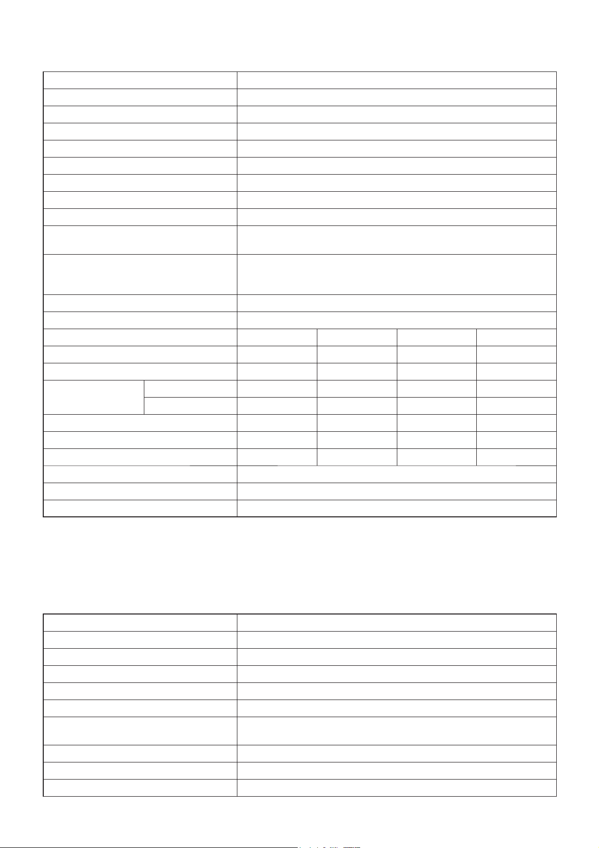
2. Specifications
Model name VL-220CZGV-E, VL-220CZGV-EB
Heat exchange system Heat recovery ventilating system
Heat exchanger material Water-resistant paper sensible heat exchanger
Cladding Galvanized steel sheet
Heat insulation material Noncombustibility polyethylene foam
Motor EC motor
Filter Non-woven fabrics filter (Gravitational method 82%, EN779: 2012: G3)
Surrounding air condition Shall be between 0°C and 40°C, 80%RH or less
Suction air condition Shall be lower than 40°C, 95%RH
Supply fan operation under low outdoor
temperature
Function
Electrical power supply 220-240 V/50 Hz, 220 V/60 Hz
Ventilation mode Heat recovery mode
Fan speed Fan speed 4 Fan speed 3 Fan speed 2 Fan speed 1
0°C to -5°C: Intermittent operation 24 min ON, 6 min OFF
-5°C or less: Continuous supply air stopped
Heat recovery ventilation/ Bypass ventilation, Fan speed 1,2,3,4
( When the optional motorized damper (P-133DUE-E) is used, bypass
ventilation mode can be switched.)
Running current (A) 0.60 0.29 0.18 0.11
Input power (W) 80 35 18.5 8.5
3
/h) 230 165 120 65
(m
Air volume
(L/S) 64 46 33 18
External static pressure (Pa) 164 84 44 13
Temperature exchange efficiency (%) 82 84 85 86
Noise (dB) 31 25 19 14
Weight (kg) VL-220CZGV-E: 31, VL-220CZGV-EB: 32
Insulation resistance 10 MΩ or more
Dielectric strength 1000 V AC 1 minute
Attention:
The running current, the input power, the efficiency and the noise are based on the rating air volume, and 230 V/50 Hz.
•
The noise is measured at 1.5 m under the center of the unit in an anechoic chamber.
• Temperature exchange efficiency (%) is based on winter condition.
• Mitsubishi Electric measures figures in the chart according to Japan Industrial Standard (JIS B 8628), therefore
the characteristic curves are measured by chamber method.
Model name PZ-61DR-E
Power supply requirement 12 V DC (Supplied from Lossnay unit)
Power consumption 0.3 W
2
Transmission cable Non polarized 2-wire (0.3 mm
(AWG22) sheathed cable)
Total wiring length 200 m maximum
Number of controllable Lossnay units 15 Lossnay units maximum (Max. 2 remote controllers installable)
Environmental condition
Temperature: 0 to 40°C, Humidity: 30% to 90% relative humidity (no
condensation)
Size 120 x 120 x 19 mm
Weight 0.25 kg
Color Munsell 1.0Y9.2/0.2
─ 4 ─
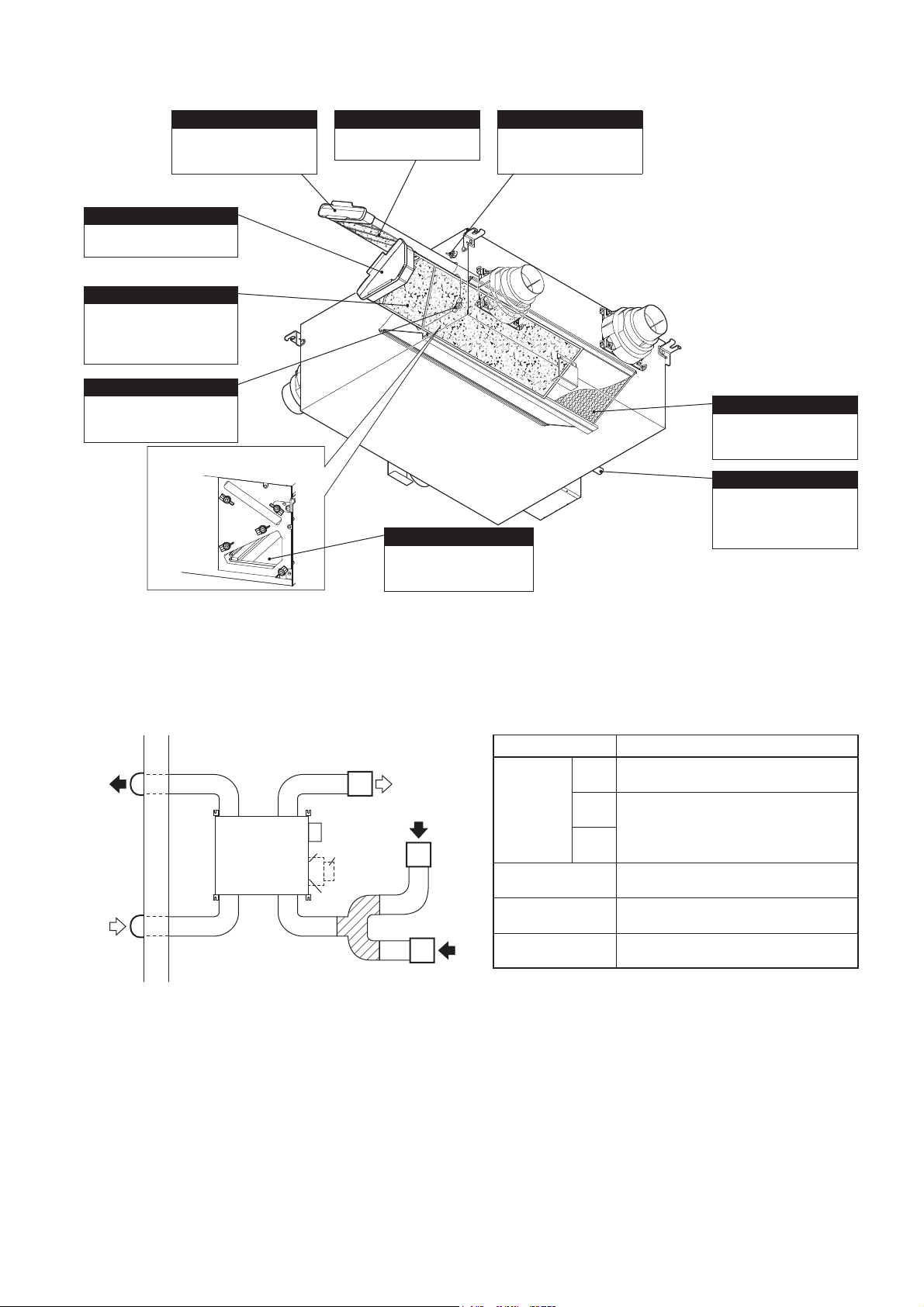
3. Names and functions of components
Exhaust air fi lter case
It holds the exhaust air
fi lter or medium ef
exhaust air fi lter.
Supply air fi lter case
It holds the supply air fi lter or
high effi ciency supply air fi lter.
Supply air fi lter
It removes insects, pollen,
dirt, dust, and other particles
from the outside air that is
taken into the room.
Supply air fi lter fi xing knob
Release it to remove the
supply air fi lter case.
(3 locations)
After the supply air fi lter case is
removed
fi ciency
Exhaust air fi lter
It prevents Lossnay core
from clogging.
Drain pan (supply air side)
It holds dew condensation
water that occurs inside the
Lossnay unit.
Exhaust air fi lter fi xing knob
Release it to remove the
exhaust air fi lter case.
(2 locations)
RA 1
OA
Lossnay core
Lossnay core exchanges
heat between the supply air
and the exhaust air.
Drain outlet
It is for discharging dew
condensation water that has
built up in the drain pan to
outside the room.
Piping example
• When connecting the RA (return air) to a bathroom, be
sure to branch the pipe into two lines and intake return
air from two locations, the bathroom and living room
(kitchen/dining room).
Outdoor
side
EA
(exhaust air)
OA
(outside air)
Indoor
side
Lossnay
RA3
RA2
RA1
(return air)
SA
(supply air)
Air duct
switching damper
(P-133DUE-E)
(Optional)
Bath
(Bathroom)
Kitchen /
dining room
Name of Connection Point
For intake from living room, toilet, wash
RA1
basin, bathroom, etc.
RA
(Return air)
EA
(Exhaust air)
OA
(Outside air)
SA
(Supply air)
For optional air duct switching damper
RA2*
(P-133DUE-E)
Exclusive for intake from living room, toilet,
RA3*
wash basin, bathroom, etc.
For exhaust air of inside air
For intake of outside air
For air supply opening to living room
Connection Location
* When RA2 and RA3 are used, use grills equipped with fi lter.
─ 5 ─
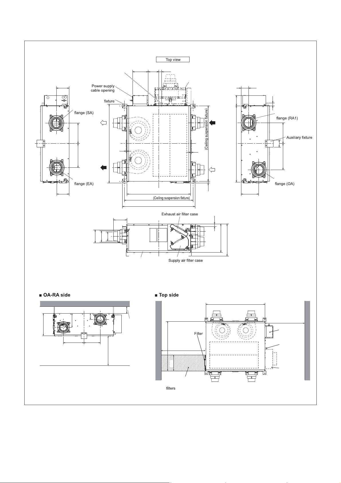
4. Outside dimensions
VL-220CZGV-E
Lossnay unit
139
Ceiling suspension
Duct connecting
SA
(supply
air)
229
271
EA
(exhaust
Duct connecting
air)
146
ij
Drain outlet
885
98
124
ij
ij
151
8
174 119 33
720
775
815
Air duct switching damper
(Optional)
RA1
(return air)
8
848
OA
(outside air)
20
31
320
362
116850
86143
31
Duct connecting
234
80
295
Duct connecting
199
Drain pan
Working space (required space around Lossnay unit)
86
234295
Leave at least
650 mm of space
RA1
Leave at least
100 mm of space
Leave at least
720
900 mm of space
245
Space required for
removing and inserting
320
OA
199
850
EA SA
OA RA1
Leave at least
700 mm of space
Circuit
Drain outlet
Air duct
switching damper
(Optional)
Unit (mm)
─ 6 ─
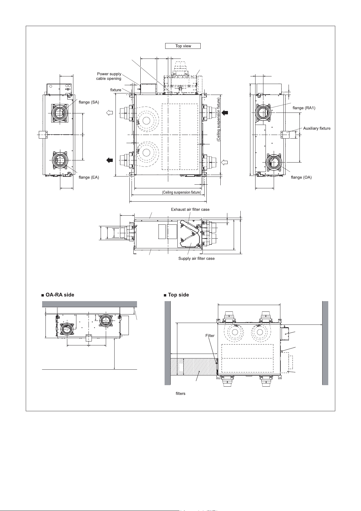
VL-220CZGV-EB
Lossnay unit
139
Ceiling suspension
Duct connecting
SA
(supply
air)
229
271
EA
(exhaust
Duct connecting
air)
Drain outlet
885
151
8
17420119 33
720
775
815
Insulation
Air duct switching damper
(Optional)
RA1
(return air)
8
848
OA
(outside air)
10
20
31
20
116850
86143
31
Duct connecting
234
80
295
Duct connecting
199
124
146
ij 98
ij
ij
Drain pan
Working space (required space around Lossnay unit)
OA
199
320 20
86
234295
Leave at least
650 mm of space
RA1
Leave at least
100 mm of space
Leave at least
720
900 mm of space
245
Space required for
removing and inserting
320
362
850
EA SA
OA RA1
Leave at least
700 mm of space
Circuit
Drain outlet
Air duct
switching damper
(Optional)
Unit (mm)
─ 7 ─
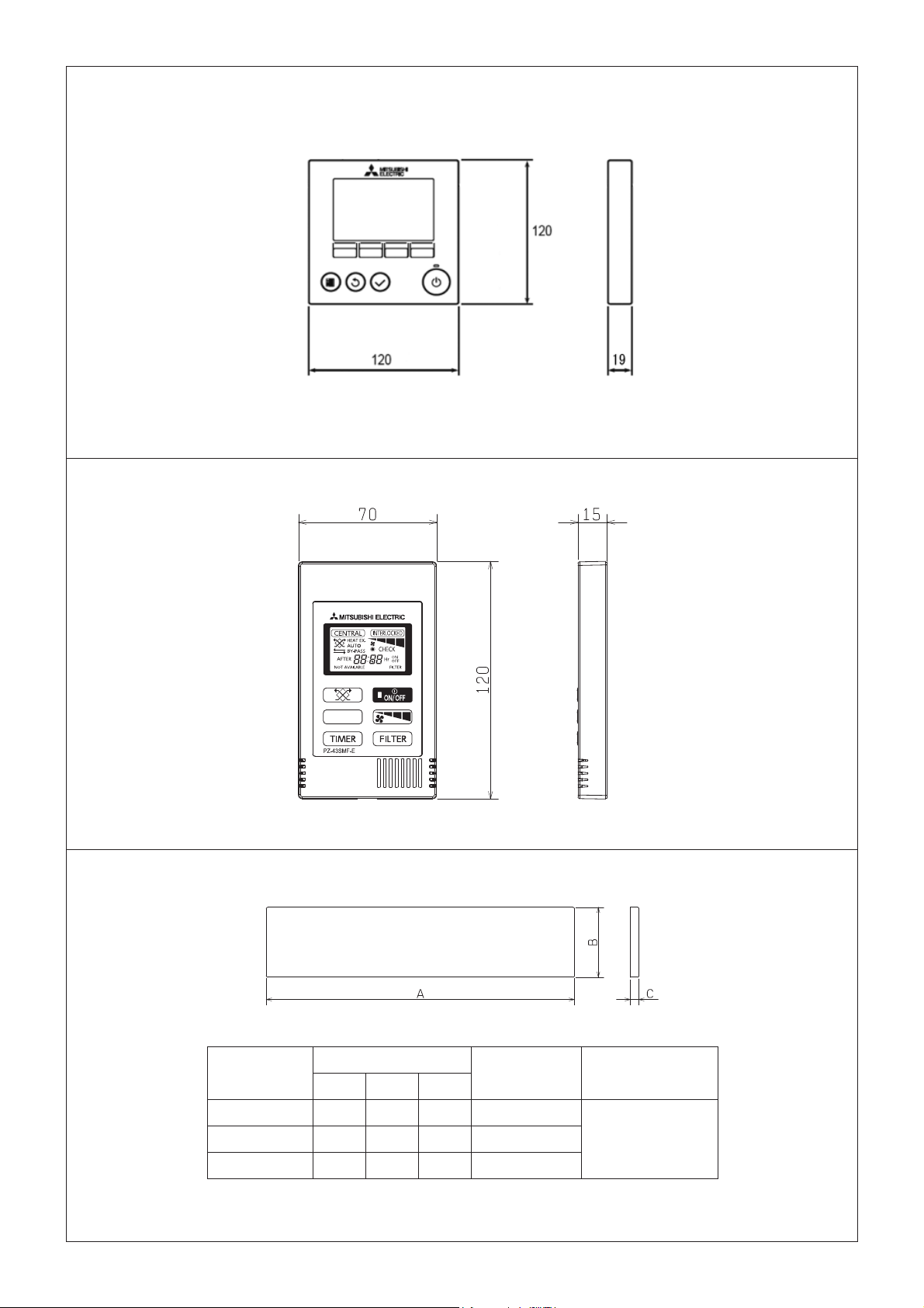
PZ-61DR-E
PZ-43SMF-E
Unit (mm)
P-220SHF-E, P-220EMF-E, P-220F-E
Model
Dimension
ABC
The number of
filters per set
P-220SHF-E 362 189 15 2
P-220EMF-E 353 183 15 2
P-220F-E 355 184 15 2
Note:
• Lossnay unit is provided with one set of the fi lters.
─ 8 ─
Unit (mm)
Applicable model
VL-220CZGV-E
VL-220CZGV-EB
Unit (mm)
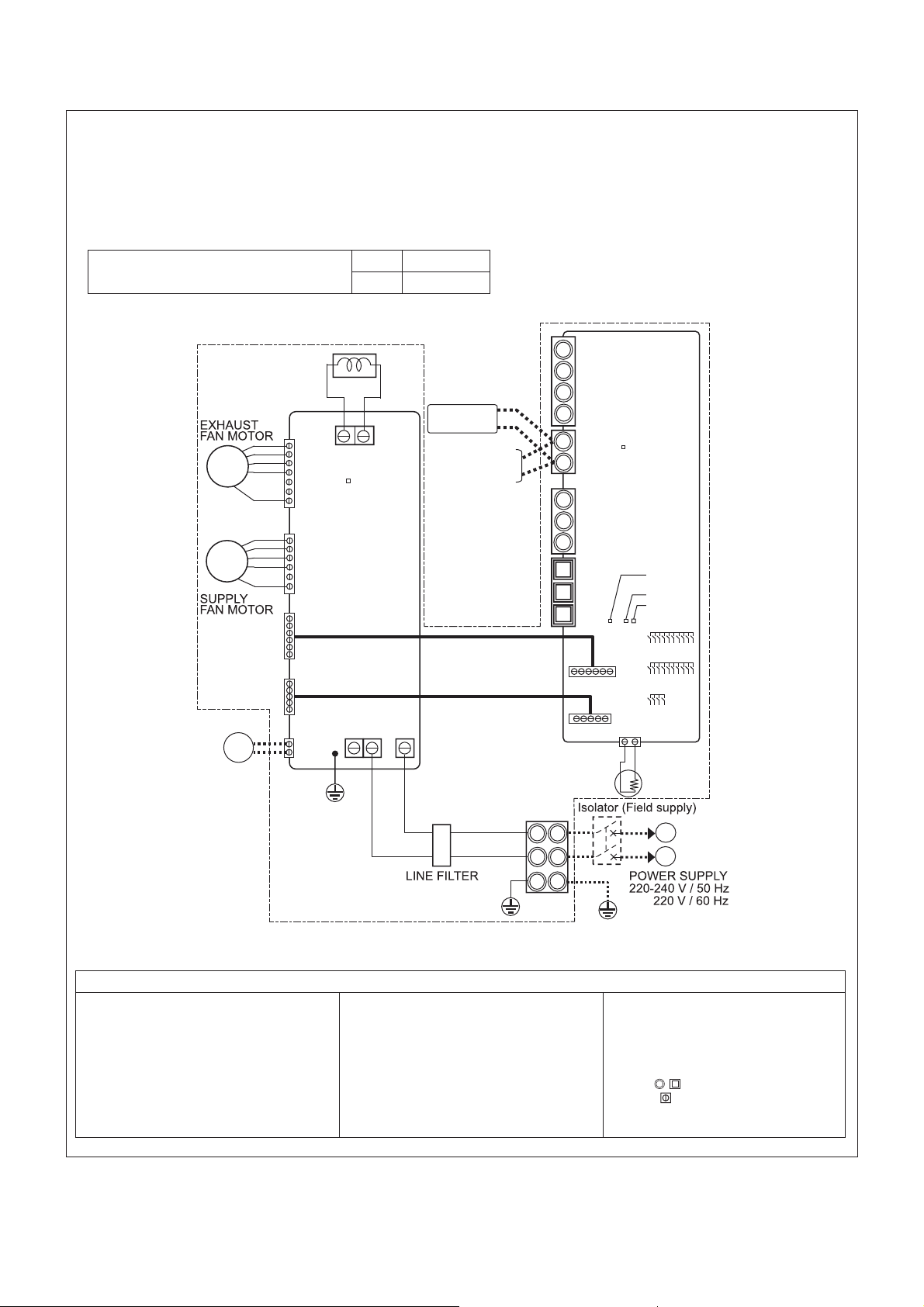
5. Electrical wiring diagram
VL-220CZGV-E, VL-220CZGV-EB
* TM1, TM4 shown in dotted lines are fi eld work.
* CN7 (DAMPER) is optional.
* Be sure to connect the earth wire.
* A power supply isolator must be installed.
* Always use an isolator for the main switch power connection.
* Select proper circuit breaker according to the electrical current information in the chart below.
Inrush current after power supply ON
REACTOR
M
1
M
2
GM
DAMPER
(Option)
10 ms 6.1 A
100 ms 3.6 A
TAB3,4
CN9
LED6
Lower Printed
Circuit Board
(Power circuit board)
CN10
CN119
CN118
TAB2TAB5 TAB1
CN7
PZ-61DR-E
PZ-43SMF-E
2nd Lossnay unit
(Max. 2 units)
TM3
7
8
9
10
1
TM4
2
Upper Printed
Circuit Board
(Control circuit board)
A
TB5
B
S
TM2
1
2
3
CN19
CN18
LED3
LED4
LED2
LED1
SW6
CN22
TH1(OA)
SW2
SW5
M1: Motor for exhaust fan
M2: Motor for supply fan
GM: Motor for By-pass damper
TH1: Thermistor for outside air
SW2,5: Switch (Function selection)
SW6: Switch (Motorized damper (option) selector)
TM1: Terminal block (Power supply)
TM2: Not in use
TM3: Not in use
TM4: Terminal block (Transmission cable)
L
N
PE
TM1
Defi nition of symbols
TB5: Not in use
TAB1, TAB2, (TAB5): Connector (Power supply)
TAB3,TAB4: Connector (Reactor)
CN7: Connector (Motor for By-pass damper)(Option)
CN9: Connector (Fan motor)
CN10: Connector (Fan motor)
CN18: Connector
CN118: Connector
─ 9 ─
L
N
CN19: Connector
CN119: Connector
CN22: Connector (Thermistor OA)
LED1: Inspection indicator lamp
LED3:
Remote controller power supply indicator lamp
LED4, LED6: Power supply indicator lamp
SYMBOL
: Terminal block
: Connector on PCB
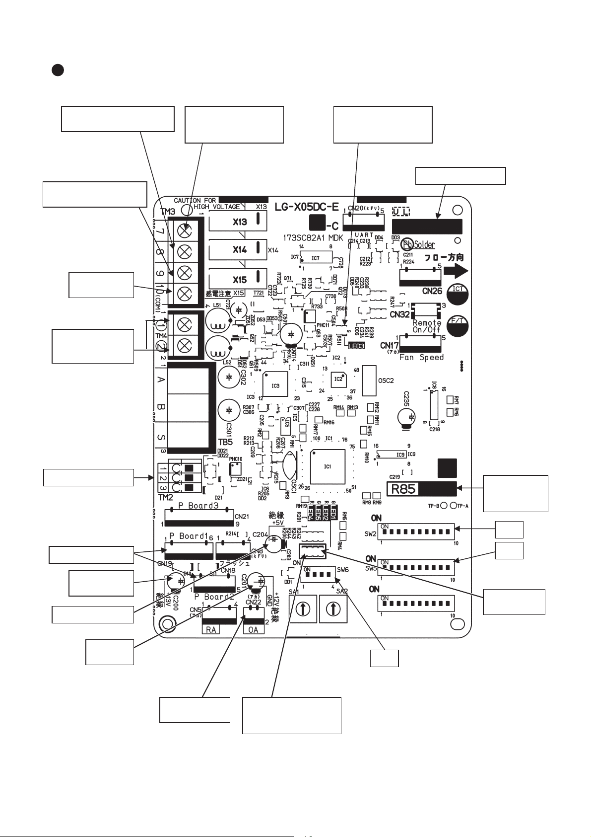
1s digit10s digit
Fed with power: lit
Not fed with power: unlit
Lot number indication
Remote controller
power supply indicator
(LED3 Green)
Bypass monitor output
Pre-heater output
(Between 7 and 0)
During bypass mode: 0 ȍ
During heat recovery mode: ȍ
Malfunction monitor output
(Between 8 and 0)
Error: 0 ȍ
Normal: ȍ
Operation monitor output
(Between 9 and 0)
When Lossnay is operating: 0 ȍ
When Lossnay is stopped:
ȍ
Monitor output
COM
Remote controller
(PZ-61DR-E, etc.)
10 to 13 V DC
External control input
Power circuit board
5 V DC (Insulated)
Power for the circuit
12 to 14 V DC
(Insulated)
GND
(Insulated)
Fed with power: lit
Not fed with power: unlit
SW6
Air duct switching damper selector
(Only when the air duct
switching damper (P-133DUE-E)
is installed)
SW2
SW5
Function selection
switch
Indication of the
microcomputer
software version
Error indicator
(LED1 Green)
Normal: unlit
Error: blinking
During delay operation: lit
Power supply indicator
for the circuit
(LED4 Red)
Outdoor air (OA)
thermistor
6. Circuit board diagrams
Circuit board diagram and check points
(1)
Control circuit board
─ 10 ─
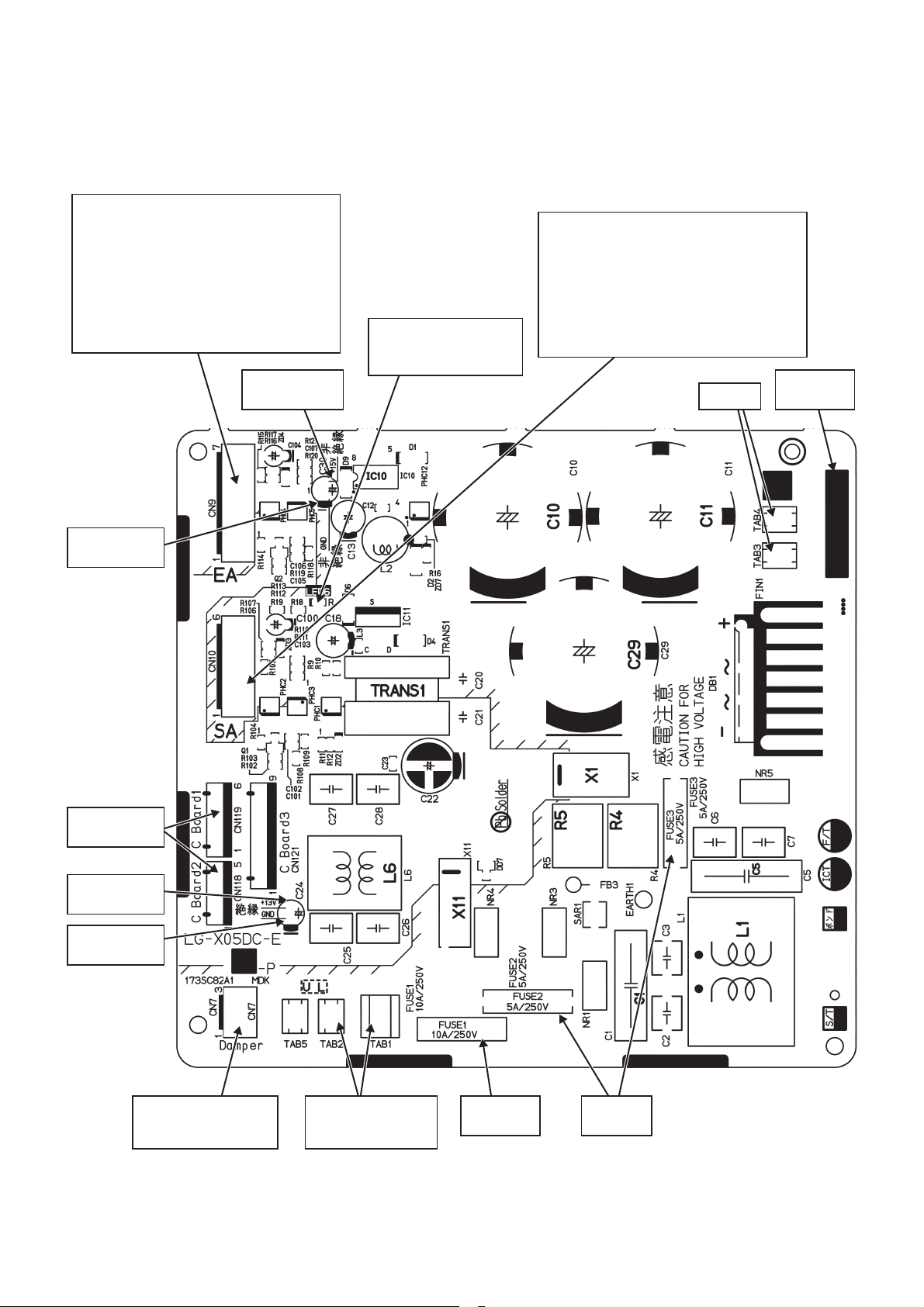
(2)
Power circuit board
Caution:
The power circuit board is not insulated from the power line (high voltage part), except for the connection part
(CN118 and CN119) with the control circuit board. Also, even when the power supply is cut off, the capacitor is
charged. Therefore, wait for at least five minutes before starting work.
Exhaust fan motor (CN9)
Pin No. of the connector
1Power for the motor: 280 to 360 V DC
2Not used
3Not used
4GND
5Power for motor control: 14 to 16 V DC
6Speed command voltage: 0 to 6 V DC
7Rotational speed pulse
14 to 16 V DC
(Not insulated)
Power supply indicator
for motor control
(LED6 Red)
Fed with power: lit
Not fed with power: unlit
Supply fan motor (CN10)
Pin No. of the connector
1Power for the motor: 280 to 360 V DC
2Not used
3GND
4Power for motor control: 14 to 16 V DC
5Speed command voltage: 0 to 6 V DC
6Rotational speed pulse
Reactor
Lot number
indication
GND
(Not insulated)
Control circuit
board
12 to 14 V DC
(Insulated)
GND
(Insulated)
Damper motor output
220 to 240 V/50 Hz
220 V/60 Hz
(Only when the air duct
switching damper (P-133DUE-E)
is installed)
Power supply input
220 to 240 V/50 Hz
220 V/60 Hz
Fuse
10 A/250 V
─ 11 ─
Fuse
5 A/250 V
7. Troubleshooting
Work precautions
•
When removing or touching the cables, circuit board or other parts, make sure to turn off the power supply isolator.
• Even after the power supply isolator is turned off, the capacitor on the circuit board retains high voltage for a
while. Therefore, before servicing, wait for at least five minutes, and then use a tester to check that the voltage has dropped.
•
Once the power supply is turned off, be sure to wait for at least five minutes before turning the power back on again.
• When servicing, be sure to recreate the malfunction two or three times before starting repairs.
• When servicing, always take care to keep proper footing.
• Before starting the service, always turn off the power supply isolator. Sufficient care must be taken to avoid
electric shock or injury.
• Make sure to connect the power supply wires correctly.
• When removing the circuit board, always hold it at both ends and remove carefully so as not to apply force
to the surface mounted parts.
• When removing the circuit board, be careful of the metal edges on the board.
• When removing or inserting the connectors for the circuit board, hold the entire housing section. Never pull
on the lead wires.
• If it is thought that there is a circuit board malfunction, check for disconnected wires in the print pattern,
burnt parts or discoloration.
•
If the circuit board is replaced, make sure that the switch settings on the new board are the same as the old board.
The part names in the texts are standardized with the part names in the parts catalog. (There are some
exceptions.)
7-1 Service flowchart
After checking the check items below, follow the troubleshooting for servicing.
Applicable Device Applicable Model
Lossnay Heat Recovery Ventilator VL-220CZGV-E, VL-220CZGV-EB
Lossnay Remote Controller PZ-61DR-E, PZ-43SMF-E
Air Duct Switching Damper
(Lossnay Heat Recovery Ventilator System Component)
Note: This device (VL-220CZGV-E, VL-220CZGV-EB) is not compatible with M-NET. When connected to
M-NET, a malfunction may occur or an error code may be displayed.
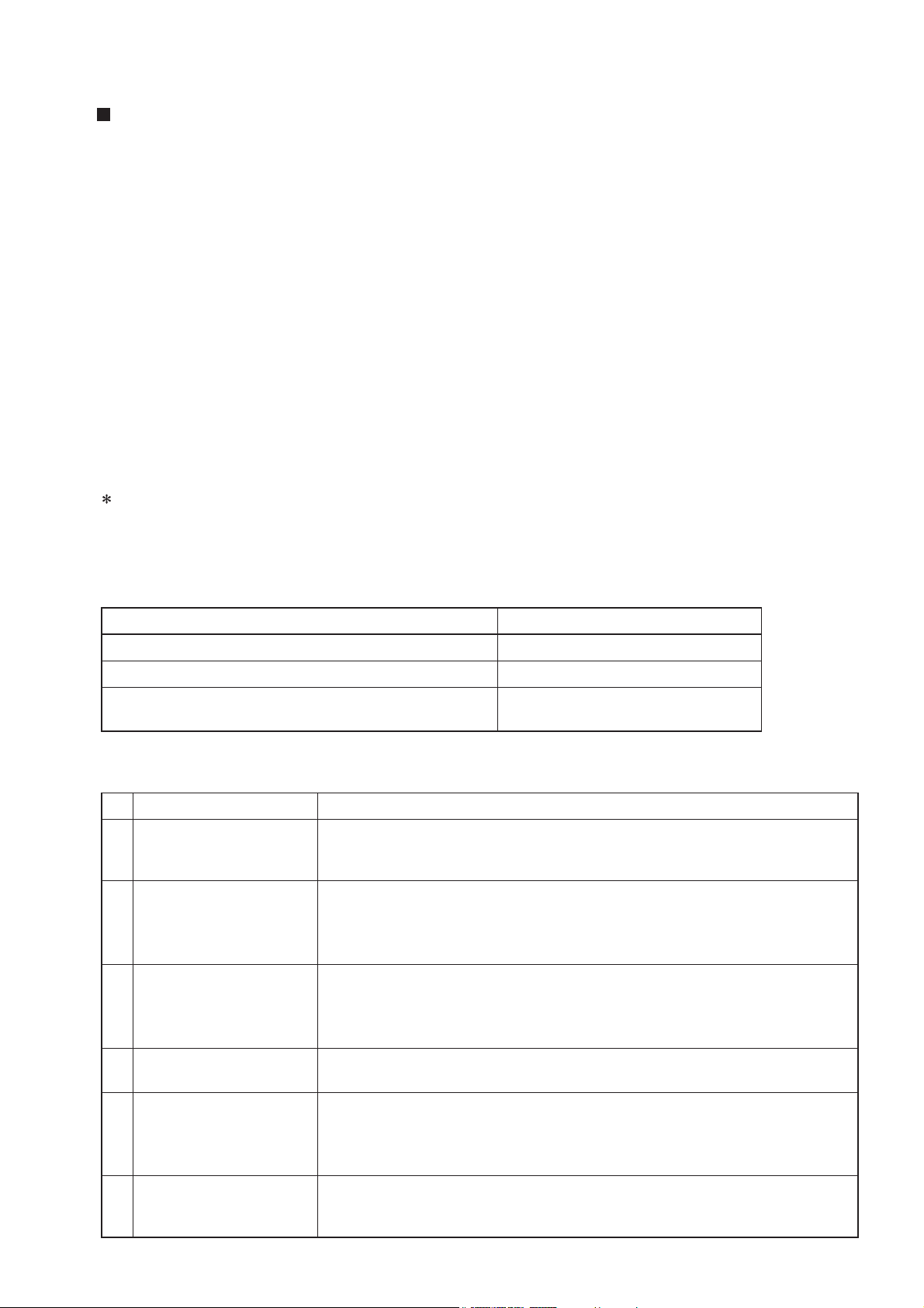
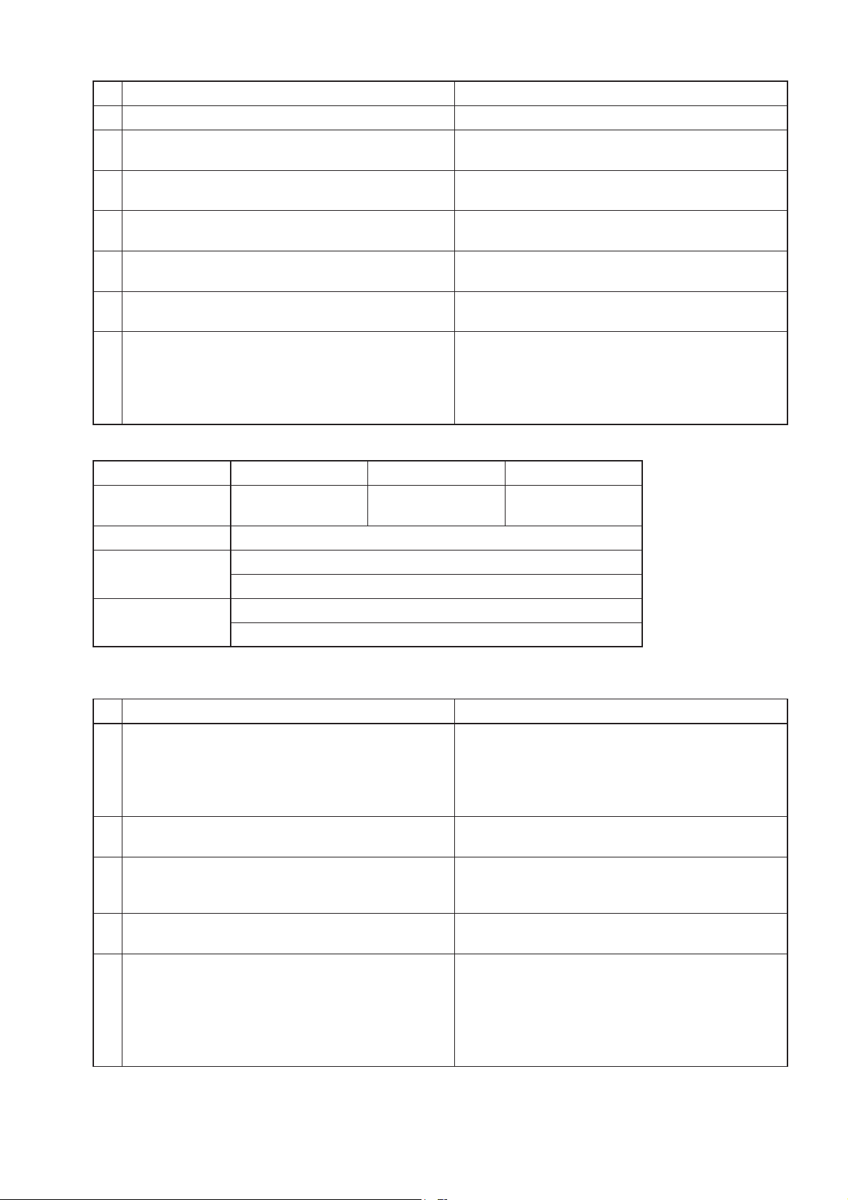
No. Preliminary check item Details
1 Product information • Model name of the product
• Serial number of the product, manufacturing lot number of the circuit board
• Microcomputer software version marked on the circuit board
2 Fault status • Fault status (For example, the fan does not operate.)
• Error code display on the remote controller
• Operation setting of the remote controller (ventilation mode setting, fan
speed setting, etc.)
3 Frequency of fault occur-
rence
4 Timing of fault occurrence • Remote controller operation performed before fault occurrence
5 System settings • Function selection switch settings of the product
6 System drawings • System Configuration
• Frequency of fault occurrence (frequency of date and time of occurrence,
regularity of occurrence, etc.)
• Operating time up to fault occurrence
• Date of start of use, date of fault occurrence
• Operating status, etc.
• Model name of the Lossnay remote controller, and whether the air duct
switching damper is installed or not
• Function settings on PZ-61DR-E when PZ-61DR-E is used
• Wiring
• Record of the Lossnay function setting statuses
─ 12 ─
P-133DUE-E
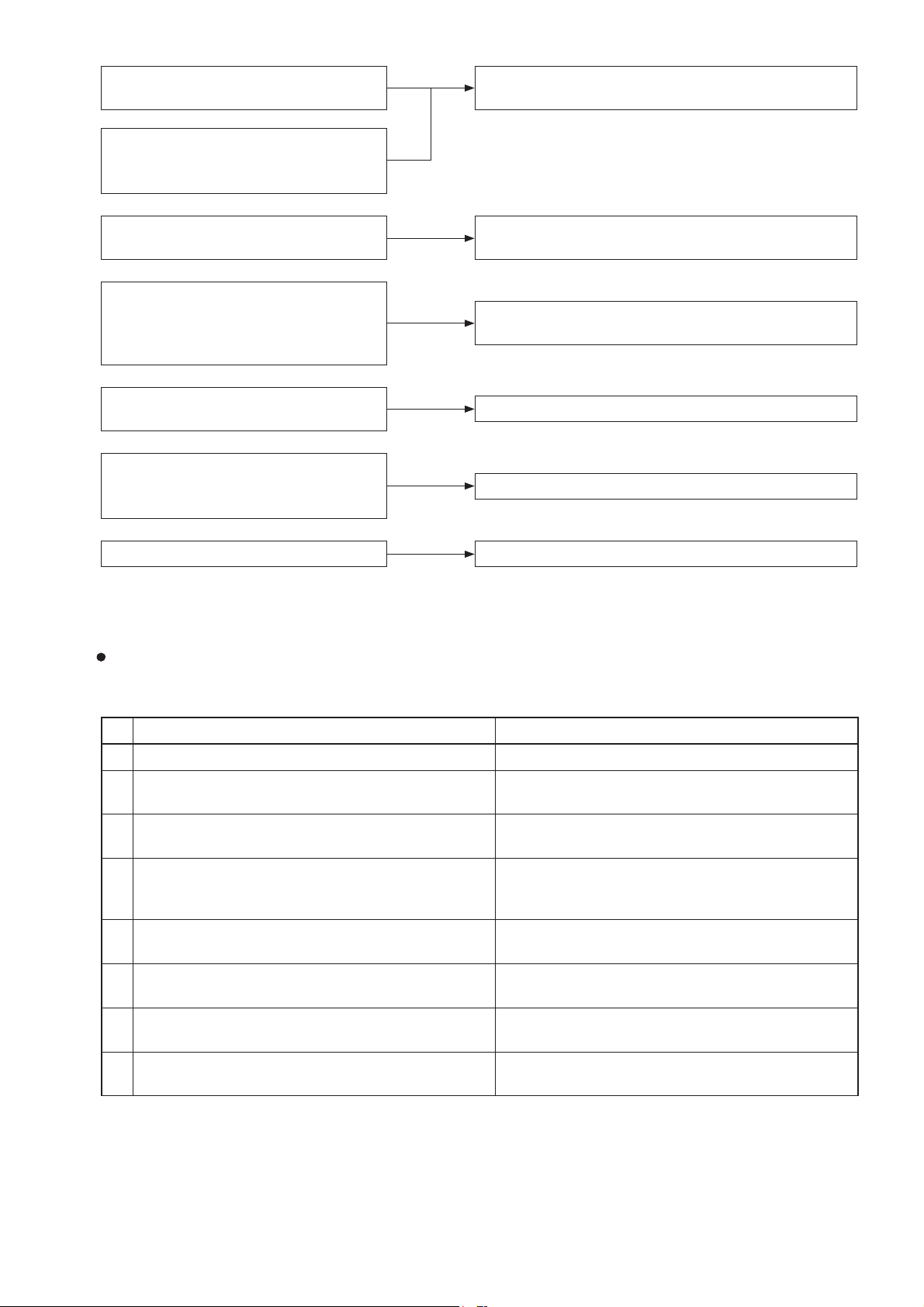
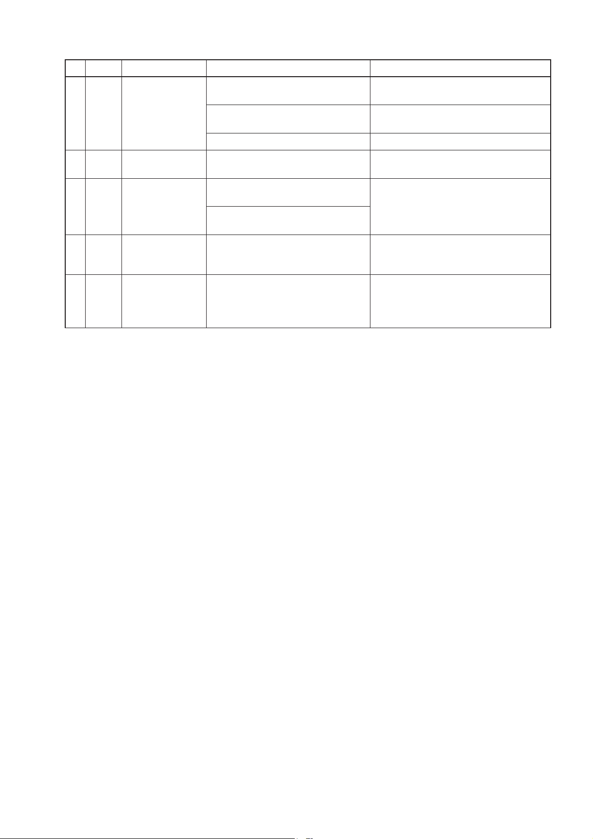
Lossnay does not work after installation
is completed.
Lossnay does not work in the trial operation after installation is completed, or
Lossnay works abnormally during use.
(1) Failure mode 1: Lossnay does not work, or
Lossnay works abnormally.
The remote controller does not work
after installation is completed.
Operations such as ON/OFF, fan speed
or ventilation mode switching are
disabled on the remote controller after
installation is completed.
Lossnay does not work properly after
installation is completed.
• An error code is displayed on the
remote controller.
• LEDs on the circuit board blink or light.
Water leaks from the Lossnay unit. (6) Failure mode 6:
(2) Failure mode 2: The remote controller does not
(3) Failure mode 3: Operations on the remote control-
(4) Failure mode 4:
(5) Failure mode 5: Error code and LED display
7-2 Check Details
(1) Failure mode 1: Lossnay does not work.
Initial Check Items
Check the following details if Lossnay does not work after installation is completed.
work.
ler are disabled.
Lossnay does not work properly.
Water leaks from the Lossnay unit.
1 Power supply
No. Check Item Corrective action
1 Is the main power supply on? Turn the main power supply on.
2 Is the current capacity of the power supply isolator
appropriate?
3 Is the designated cable used for the power supply
cable?
4 Is the specified power supply supplied to the power
supply terminal (TM1)?
220-240 V/50 Hz, 220 V/60 Hz
5 Is the power supply cable incorrectly wired, is there
a faulty connection or are screws loose?
6 Is there a faulty connection on the power supply
terminals (TM1, TAB1, and TAB2)?
7 Is there a faulty connection on the reactor terminals
(TAB3 and TAB4)?
8 Are the power supply indicator lamps (LED4 and
LED6, red) lit?
Use an appropriate power supply isolator.
Use the designated cable.
Supply the designated power supply.
Connect the cable securely and correctly, and
tighten the screws firmly.
Connect the lead wires securely.
Connect the lead wires securely.
Check the above items.
─ 13 ─
2 Transmission cables (remote controller transmission cable, and external input/output signal cable)
No. Check Item Corrective action
1 Are the designated cables used for the remote control-
Use the designated transmission cables.
ler transmission cable? (See Table 2-1.)
2 Are the designated cables used for the external input/
Use the designated cables.
output signal cable? (See Table 2-2.)
3 Are the transmission cables wired using multicore
Use the designated transmission cables.
cables?
4 Are multiple transmission cables wired in the same pip-
ing duct?
5 Is the power supply cable wired at least 5 cm away
from transmission cables?
6 Are the transmission cables connected to the desig-
nated terminal block? (See Table 2-1.)
7 Are the transmission cables incorrectly wired, is there a
faulty connection or are screws loose?
8 Is the wiring length of the transmission cable within the
Wire the transmission cable away from one
another.
Wire the power supply cable at least 5 cm away
from the transmission cables.
Connect the transmission cables to the designated terminal blocks.
Connect the cable securely and correctly, and
tighten the screws firmly.
Wire the cables within the regulations.
regulations? (See Table 2-1.)
9 Does the external input signal match the specifica-
Input the signal that matches the specifications.
tions? (See Table 2-2.)
10 Is the external input signal input to the Lossnay set as
the main Lossnay?
11 Is the function selection for the external output signal
set correctly?
Input the signal to the Lossnay set as the main
Lossnay (SW5-10 ON).
Set the function selection switches (SW2-8, 5-2,
and 5-6) on the circuit board correctly.
Set the function settings (No. 57 and 58) of PZ61DR-E correctly.
Table 2-1
Remote controller transmission cable specifications
Cable
PZ-61DR-E or PZ-43SMF-E
transmission cable
Type Sheathed cable
Number of cores 2-core cable
2
Cable diameter 0. 3 mm
(AWG22)
Total extension 200 m
Terminal block
TM4 12
─ 14 ─
Table 2-2 External input/output specifications
Function Name
External control input
(volt-free contact)
External control input
(12 V DC, 24 V DC)
Remote/local switching
Remote ON/OFF input
Fan speed 4 input (volt-free contact)
Fan speed 3 input (volt-free contact)
Fan speed 2 input (volt-free contact)
Fan speed 1 input (volt-free contact)
Bypass mode input (volt-free contact)
*Only when P-133DUE-E is installed
Fan speed switching input
(0 to 10 V DC)
Terminal or
connector on
the circuit board
TM2 13
TM2 12
CN32 13
CN32 12
CN17 12
CN17 13
CN17 14
CN17 15
CN26 12
CN26 45
Signal
specifications
Level/pulse
(Note 1)
Level/pulse
(Note 1)
Level
(Note 1)
Level
(Note 1)
Analog
Materials Used
Single-lead 0.8 to 1.2 mm dia. or
twisted lead 0.5 to 1.5 mm
2
Single-lead 0.8 to 1.2 mm dia. or
twisted lead 0.5 to 1.5 mm
2
Remote ON/OFF adaptor
(PAC-SE55RA-E)
Remote display adaptor
(PAC-SA88HA-E)
Total
extension
500 m
(Note 2)
10 m
<Caution>
• When connecting two Lossnay units and using external input/output, input the signals to the Lossnay (SW510 ON, with the smallest address setting) set as the main Lossnay.
(Note 1) The input signal must conform to the following specifications:
Level signal Volt-free contact, 12 V DC, 24 V DC, the duration of ON and OFF should be 10-second
or more.
Pulse signal Volt-free contact, 12 V DC, 24 V DC, the duration of ON should be 200 msec. or more,
and minimum 10-second absence is necessary to the next pulse .
In the case of relay contact input, use a relay having a contact rating of 15 V DC/0.1 A or higher and a
minimum applicable load of 1 mA or less.
(Note 2) Check the specifications of the external device.
─ 15 ─
3 Monitor output signal cable
No. Check Item Corrective action
1 Is the signal cable wired by multicore cable? Wire the cable using a 2-core cable.
2 Are the signal cables and transmission cables wired
in the same piping duct?
3 Is the power supply cable wired at least 5 cm away
from signal cables?
4 Is the signal cable connected to the designated
terminal block? (See Table 3-1.)
5 Is the signal cable incorrectly wired, is there a faulty
connection or are screws loose?
6 Is the output capacity of the signal cable within rat-
Wire the signal cables away from the transmission
cables.
Wire the power supply cable at least 5 cm away
from the signal cables.
Connect the signal cable to the designated terminal
block.
Connect the cable securely and correctly, and
tighten the screws firmly.
Use the signal cable within rating.
ing? (See Table 3-1.)
7 Is the function selection for the external output
signal set correctly?
Set the function selection switches (SW2-8, 5-2,
and 5-6) on the circuit board correctly.
Set the function settings (No. 57 and 58) of PZ61DR-E correctly.
(See the Lossnay technical manual.)
Table 3-1 Monitor Output Specifications
Terminal block
Function Name
TM3 90 TM3 80 TM3 70
Operation monitor
After-heater
Malfunction monitor Bypass monitor
Signal specifications Volt-free contact
240 V AC, 1 A
Output rating
24 V DC, 1 A
220 V AC, 100 mA
Min. applicable load
5 V DC, 100 mA
4 Function setting (See the Lossnay technical manual for details.)
No. Check Item Corrective action
1 Is the main Lossnay set correctly? Check the function selection switch (SW5-10) on
the circuit board.
When an external signal is input to two Lossnay
units, set one of the units as the main Lossnay
(SW5-10 ON).
2 Are the function selection switches on the circuit
board set correctly to suit the required application?
3 Is the applicable model used as the Lossnay re-
mote controller?
Set the function selection switches (SW2 and SW5)
on the circuit board correctly.
Use PZ-61DR-E or PZ-43SMF-E.
(The air conditioner remote controller including
PAR-31MAA cannot be used.)
4 When PZ-61DR-E is used, are the function selec-
Set the function selections correctly.
tions set correctly to suit the required application?
5 Was a function set with the function selection
switches on the circuit board after the function is set
with PZ-61DR-E?
Set the function again with PZ-61DR-E.
For the function that can be set with both PZ61DR-E and the function selection switches, if the
function is set to other than "DIP-SW priority" with
PZ-61DR-E, setting with the function selection
switches is disabled.
─ 16 ─
5 LED Indications on the circuit board
No. LED Contents Check Item Corrective action
1 LED1
(green)
Lossnay main unit
error indicator
Blinking: Starting up, or error occurred
See Failure Mode 5.
Lit: During delay operation Lossnay operates after the delay time
has passed.
Unlit: Other than above It is normal.
2 LED2
(red)
3 LED3
(green)
4 LED4
(red)
M-NET System
error indicator
Remote controller power supply
indicator
Power supply
indicator (control
Unlit It is normal.
Lit: Power supplied to the remote
controller (Main Lossnay)
Unlit: Power not supplied to the
remote controller (Sub Lossnay)
The LED goes out when power is supplied to the remote controller from another Lossnay unit in the case of using
two Lossnay units.
Check that this LED is lit The LED lights while power is being
supplied to the control circuit board.
circuit board)
5 LED6
(red)
Power supply
indicator (power
circuit board)
Check that this LED is lit The LED lights while power is being
supplied to the power circuit board.
(Do not touch components on the circuit
board when the LED is lit.)
─ 17 ─
 Loading...