

Page 1

VENTILATING FAN
MODEL:
MANUAL AND INSTALLATION PROCEDURE
PRODUCT APPEARANCE
ADDITIONAL PART
SCREW (9 PCS)
REMARK : IS THE ALPHABET OF DEVELOPEMENT NUMBER
CAREFULLY READ INSTALLATION MANUAL AND THE PRODUCT
SHOULD BE INSTALLED BY THE SPECIALIZED TECHNICIAN.
Page 2
ESSENTIAL SAFETY PRECAUTIONS
WARNING
FAILURE TO COMPLY DEATH OR BODILY INJURY MAY RESULT.
1. Do not use the ventilator when damages found on wire or other components. This may
cause fire and electric shock.
2. Do not switch on the ventilator when the assembling is not completed with all
components such as airguide and propeller as bodily injury may result.
3. Do not use the ventilator or its electrical components when they are wet as injury from
PROHIBITED
electric shock may result.
4. Do not contact the ventilator or its electrical components when your hands are wet.
5. Do not modify the ventilator as severe injury may result.
6. Be sure to unplug the ventilator from the main supply prior to cleaning or repairing the
ventilator.
CAUTIONS
FAILURE TO COMPLY BODILY INJURY OR PROPERTY DAMAGE MAY RESULT.
1. It is dangerous to insert fingers or object into the ventilator propeller or rotating component.
2. Do not use harsh cleaners or solvents on the ventilator as this may cause deforming on plastic
components and damaging other components.
3. Do not install the ventilator at the location of heat source such as gas/electric fire nearby; location of
high humidity, location of solvent dampness, as fan damage or fire may result.
4. The appliance is not intended for use by young children or infirm persons unless they been adequately
supervised by a responsible person to ensure that can use the appliance safety.
INSTALLATION
INSTALLATION CAUTIONS
1. Before installation and assembling the Ventilator, please study the manual.
2. The installation might be suggestion from Service Center or Sales Agency.
3. To be install with stable ceiling to bear the weight and vibration of Ventilator.
4. To be installed metal pipe by do not install metal parts contact with conductive material which
be coated on the wooden.
5. The Accessory pipe hood more available to protect insect or bird and rains.
6. Do not install the ventilator and control switch in bathroom or high humidity area may cause electric
short-circuit.
7. Do not install the fan in:
- Area containing high amount of oil, chemical, dust.
- The back-flow of gases into the room the open fuel of gas or other open fire appliances.
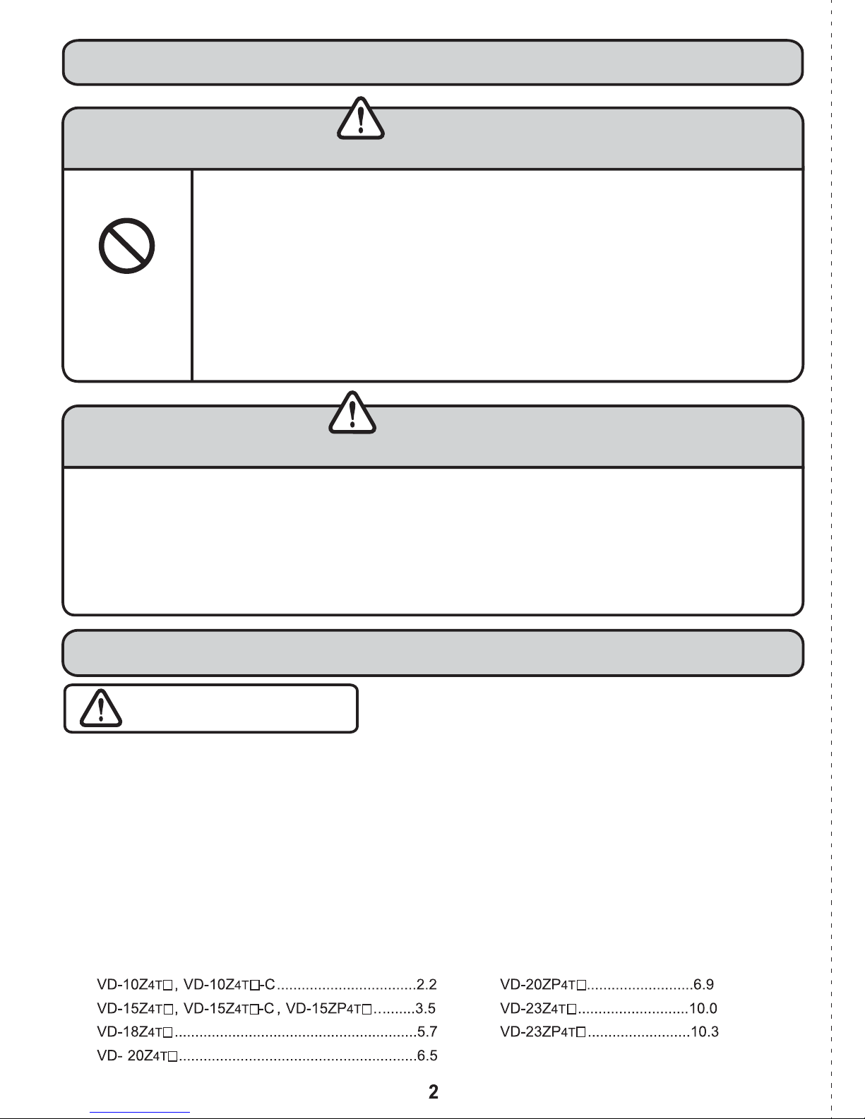
8. The Installation area might be stable ceiling to bear the weight of ventilator in each model as;
Kg Kg
Kg
Kg
Kg
Kg
Kg
Page 3
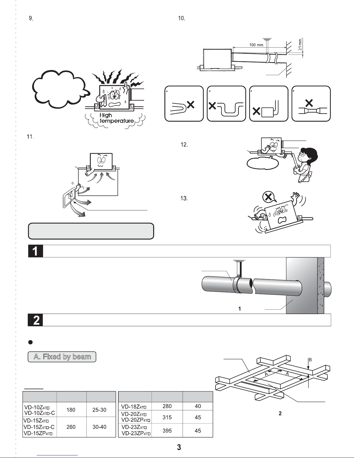
In case of installation at high temperature area, the
capacity of insulator parts such as motor, capacity
might drop and be cause of electric leakage.
Moreover, not well-done lubricated shaft might be
hotter as well as motor. To protect those conditions
do not install the product at the high temperature
area.
Watch out!!
It’s Electric leaking
In the closed building or unable to exhaust the
air area, the hole should be installed to drain in
the fresh air.
Should avoid pipe bending as belows:
SHARP BENDS
Should inclined install smoke pipe by additional duct
higher than smoke pipe on the wall
1mm/100mm to protect the rain water.
WALL
MANY BENDS
The installed
ceiling should be
easy to check
from opened gap.
BEND RIGHT BY
THE AIR OUTLET
OPENED GAP
VERY NARROW
CONNECTION
In case of loosen
AIR DRAIN IN GAP
installation, It’s
might occur
vibration or loud
noise.
INSTALLATION
TO SELECT INSTALLATION AREA AND WALL FOR DRILLING THE AIR-EXHAUSTED HOLE
To Install duct from the air-exhausted hole to
additional duct by fixing it with ceiling to protect the
overload. Diameter of duct is 100 mm(VD-10/15) or
150 mm (VD-18/20/23) made from vinyl chloride,
aluminium, steel. Before Installation Please carefully
read Installation of caution.
VENTILATING FAN INSTALLATION
There are two methods to install the product.
To prevent the contact with the propeller, install the ventilating fan above 2.3 m from the floor.
A. Fixed by beam
DUCT
Figure.
BEAM
WALL
(A1) To make a frame with beam and sub beam as
Figure.2 and dimension in Table 1.
Table.1
Model
Dimension A Dimension B
Model
Dimension A Dimension B
SUB BEAM
Figure.
Unit : mm.
Page 4
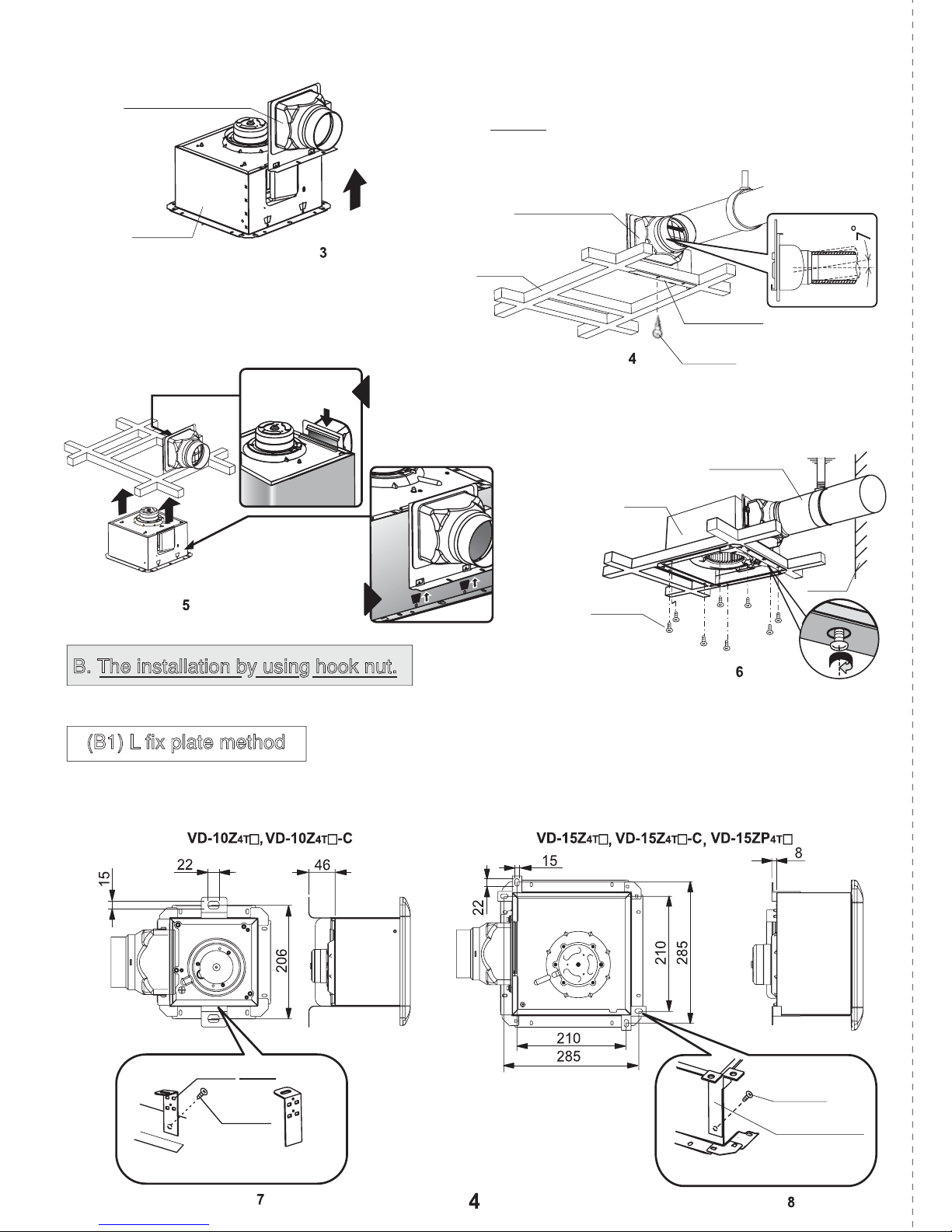
(A2) To take off additional duct as the arrow
direction as Figure.3
(A3) To install the wing of additional duct under sub
beam and fix additional duct with main duct. Then
fix additional duct with sub beam at “A” position with
ADDITIONAL DUCT
screw as Figure.4
Remark
In case of vinyl chloride duct, the inclination from the
product to ended-duct should not greater than 7 degree.
ADDITIONAL
BODY
Push up
DUCT
Figure.
(A4) To install the product with additional duct and
BEAM
push product until lock point of additional duct
lock hook of product as Figure.5
To lock
product with
upper
additional duct.
(A5) To check the completeness and install
product with beam by screwing with 8 screws.
as Figure.6
Figure.
LETTER “A”
HOLE
SCREW
ADDITIONAL
DUCT
BODY
To lock product
with lower
additional duct
Figure.
as picture.
B. The installation by using hook nut.
There are two methods, using L fix plate, and sub frame
SCREW
Figure.
WALL
SCREW
(LETTER “A” HOLE)
(B1) L fix plate method
(B1.1) To set hook nut with ceiling and install L fix plate with the product as the Figure.7, 8 and 9
Model : Model :
L fix plate
SCREW
Q.14UL3)BEEJUJPOBM!QBSU*
Figure.
SCREW
L fix plate
Q.16UL)BEEJUJPOBM!QBSU*
Figure.
Page 5

Table shown dimension of position of “L” Fix plate
each model as followed
MODEL
DimensionADimensionBDimension
C
Unit:mm.
As shown at Figure.9
L fix plate
P-08TK (ADDITIONAL PART)
(B1.2) To fix the product with hook nut and
horizontal install the product as right
picture. as Figure.10
SCREW
L FIX PLATE
Figure.
HOOK NUT
NUT
WASHER
(B2) To use SUB FRAME
(B2.1) Install HOOK NUT with the ceiling and
install sub frame with the Body.
The sub frame of model
Figure.11
Caution
2 Central holes to be use.
HOLE
Table shown each SUB FRAME model dimension
MODEL
Figure.
The sub frame of model
SUB FRAME
Dimension
A
Dimension
RUBBER
WASHER
Figure.12
HOLE
Figure.
DimensionCDimension
B
D
Unit :mm.
Figure.
Unit:mm.
Page 6

(B2.2) To set 2 wooden parts with sub frame
by using screws as the Figure.13
(B2.3) To Install sub frame to ceiling with Hook nut as
the Figure.14
Caution
SCREW
as Figure.15.
ADDITIONAL
DUCT
BODY
:Do not obstruct hook nut-hole on sub frame.
Figure.
SUB FRAME
WOODEN
PUSH UP
Figure.
HOOK-NUT
SUB FRAME
Figure.
(B2.5)
To set the product by turning the front to open air hole to
exhaust the air from the wall and fix the additional duct
with sub frame by screwing through “A” letter hole as
Figure.16
ADDITIONAL DUCT
SCREW
HOOK NUT
WOODEN
SUB FRAME
Figure.
(B2.6) To set the product with additional duct with
hook of product and additional duct Figure.17
SUB FRAME
BODY
ADDITIONAL DUCT
Figure.
as Figure.19
SUB FRAME
MODEL NAME
as Figure.18
SUGGESTION
ADDITIONAL
DUCT
WOODEN
Figure.
SCREW
(B2.9) After installed ceiling board, to hammer from the
inside for protecting the slide of sub frame and
ceiling as Figure.20
SUB FRAME
WOODEN
BEAM
TAPE
Figure.
Unit:mm.
NAIL NAIL
SUB FRAME
Figure.
Page 7

TO INSTALL PIPE FROM BODY TO WELL EXHAUST PIPE
To adhere aluminium tape at connecting point
between exhaust pipe and additional duct to
protect air leakage as Figure.21
TAPE
DUCT
Figure.
ADDITIONAL PART(NOT INCLUDE ON PRODUCT)
“L” fix plate, Sub frame, Duct (Iron, plastic, Aluminium, Stainless steel), Hood.
TO INSTALL LEAD WIRE SHOULD BE DONE AS NECESSARY
LEAD WIRE INATALLATION CAUTION
1.Fan and lead wire installation should be suggested by service center or specialize
technician.
2.Before installation and Assembling the fan please read installation manual carefully.
3.Installation leadwire carefully, in case missing occure may cause circuit-shorten.
4.Installing lead wire in pipe should be use the standard piping accesories (available from
hardware store),and then connect to the terminal.
TERMINAL DIAGRAM AND LEAD WIRE CONNECTION
Separate each model group as followed
VENTILATOR MAIN UNIT
VVF
LEAD WIRE
1.6 mm or
2.0 mm
Thermal
fuse
WALL
SWITCH
CIRCUIT
BREAKER
*
VVF
LEAD WIRE
1.6 mm or
2.0 mm
VENTILATOR MAIN UNIT VENTILATOR MAIN UNIT
Thermal
fuse
WALL
*
SWITCH
CIRCUIT
BREAKER
VVF
LEAD WIRE
1.6 mm or
2.0 mm
Thermal
fuse
WALL
SWITCH
CIRCUIT
BREAKER
*
Figure.
Page 8

VENTILATOR MAIN UNIT
Thermal
fuse
VVF
LEAD WIRE
1.6 mm or
2.0 mm
WALL
*
SWITCH
157
HOOK
SLIDE COVER
*
WALL SWITCH is obtained from hardware store.
Remark :
1. Installation location of circuit breaker should be easy
to operation and shut off.
2. The circuit breaker shall have a contact separation in
all poles and provide full disconnection under
overvoltage category III condition in accordance
with the wiring rules.
CIRCUIT
BREAKER
Pay attention to connect the wire,1 wire
from power supply especially common
wire connect with the “N(COM)” terminal.
Figure.
CAUTION
Continue
Leadwire size for installation
1. Must use indoor wiring VVF cable Ø1.6 mm or Ø2.0 mm
2
2
2. In case of install ground wiring must install ground at least
1.0 mm and must install to Industrial Standard
Ground Rod by specialized technician.
2
General connector and electric line procedure
Do not connect the ground wire to Gas duct, Water pipe
Lightning rod or Telephone line because may
occur electric shock.
To peel off lead wire 10 mm.
To pull wiring approx. 150 mm from the product.
To separate wiring from connecting board, then push
red button on connecting board and pull each wiring
with Screw Driver.
Lead wire connector method
Figure.
CAUTION
LEAD WIRE
CONDUCTOR
Insert the tip of the flathead
screwdriver here.
SCREW
TERMINAL
COVER
STRIPPED WIRE
Model :
(1) Remove screw and unlock cover, weave VVF (Ø1.6, Ø2.0)
through rubber button until it can be completely passed.
(2) The product is used in high humidity area, the ground wiring
should be installed.
(3) To lock the cover and fix to screw.
Model :
(1) Remove screw and unlock cover, weave VVF (Ø1.6, Ø2.0)
through rubber button until it can be completely passed.
(2) The product is used in high humidity area, the ground wiring
should be installed.
(3) To lock the cover and fix to screw.
(as Figure. )
as Figure.
GROUND
TERMINAL
TERMINAL
COVER
LEAD WIRE
GROUND
TERMINAL
TERMINAL
Figure.
SCREW
STRIPPED WIRE
TERMINAL
Figure.
Page 9

Model:
as Figure.
(1) Remove screw and unlock cover, weave VVF (Ø1.6, Ø2.0)
through rubber button until it can be completely passed.
(2) The product is used in high humidity area, the ground wiring
should be installed.
(3) To lock the cover and fix to screw.
GROUNDING
TERMINAL
STRIPPED WIRE
SCREW
TERMINAL
COVER
LEAD WIRE
Figure.
Model:
as Figure.
(1) Remove screw and unlock cover, weave VVF (Ø1.6, Ø2.0)
through rubber button until it can be completely passed.
(2) The product is used in high humidity area, the ground wiring
should be installed.
(3) To lock the cover and fix to screw.
GROUNDING
TERMINAL
STRIPPED WIRE
TO INSTALL CEILING BOARD AND CEILING
Caution
To leave a gap between the product and
ceiling board approx. 2-3 mm.
Figure.
BEAM
CEILING
To prevent the contact with the propeller,
install the ventilating fan above 2.3 m from
the floor.
2-3 mm.
SCREW
TERMINAL
COVER
LOW
HIGH
COM
Figure.
More than 2.3 m
from the floor.
FLOOR.
TO INSTALL GRILLE
To hold grille’s spring of both side and insert to
elliptical hole of product then, release spring and
push cover to fix with the product as Figure.29.
Remarks:
Grille of VD-10Z4T -C, VD-15Z4T -C, VD-18Z4T ,
VD-20Z
4T , VD-20ZP4T , VD-23Z4T , VD-23ZP4T
can be reverse 90 ° by changing SPRING.
Spring grille assembling
MODELMODEL
Put SPRING in
Insert
SPRING
Insert PIN
Twist to CLOSE
locking with PLIERS
Figure.
ELLIPTICAL
HOLE
SPRING
GRILLE
Figure.
MODEL
SPRING
PLIERS
CATCH
Page 10

USAGE
4T
For VD-10Z
, VD-10Z
CAUTION USAGE
In case of installed in restroom having hot bathtub,
after draining the hot water, please cover bathtub
to prevent the evaporation of hot stream.
Be Quick
Close it
Figure. Figure.
OPERATING PROCEDURE
Switch boarded exclude the product, Use switch which be sold generally.
4T
-C, VD-15Z
Yep
4T ,
VD-15Z
4T
-C, VD-15ZP
Various parts are made from plastic material, do not
bring flammable objects to be near them that they
might possibly be deformed or melted.
4T
.
Remark : Installation location
of switch should be easy to
operate and shut off.
Air volume selector is available
Only this followed model
VD-20ZP4T2,VD23Z4T2,VD-23ZP4T2
START TO EXHAUST THE AIR
Switch on the wall. Switch on the wall.
OFF
SET THE AIR VOLUME SELECTOR
SWITCH TO “HIGH.”
LOW
ON
HIGH
STOP TO EXHAUST THE AIR
OFF
SET THE AIR VOLUME SELECTOR
SWITCH TO “LOW.”
LOW
ON
HIGH
MAINTENANCE
1. Be always turn switch off or pull the circuit breaker down before cleaning and
musn’t wet the motor or other electrical parts.
2. Cleaning the dirty part with water/neutral detergent damped-cloth to protect
water driping into electrical part, and then wipe with a dry cloth.
3. Do not use any chemical to clean the plastic part it may cuase damage to
product.
4. In case of intensive dirt on the grille, the air blow will be less causing loud
noise. To protect such condition, should often clean the grille.
5. To remove the grille, pull the grille, then squeeze the spring and take it from
the elliptical hole of fix spring as Figure.29 in page 9.
6. Disconnect the power when not in use.
Page 11

REPAIRING PRODUCT
1. This product must not be assembled under any circumstances. Only authorized repair technicians are
qualified to conduct diassembly and repairs.
(Failure to heed this warning may result infire, electric shock or injury.)
2. Must use genuine spare part from Service center or Sales Agency.
3. Do not modify any electric part, if failure to heed this warning may cause injury.
DIMENSIONS
NPEFM!;
HOLE FOR FIX
SCREW(8POINT)
LEAD WIRE
Unit : mm.
INSERT HOLE
NPEFM!;
Unit : mm.
NPEFM!;
HOLE FOR FIX
SCREW(8POINT)
LEAD WIRE
INSERT HOLE
Unit : mm.
Dimension table was shown
at Page.12
HOLE FOR FIX
SCREW(8POINT)
LEAD WIRE
INSERT HOLE
Page 12

TABLE:
No.
Each part dimension of
PART NAME
PART NAME
PICTURE
PLASTIC
MODEL
METAL
ADDITIONAL
DUCT
BODY
PROPELLER
FAN
AIR GUIDE
ORIFICE
GRILLE
ALL MODEL
ALL MODEL
REMARK :
NOT HAVE ORIFICE (No. 5) IN THIS FOLLOWED MODEL
K0588N41401
 Loading...