

Page 1

AUTOMATIC
TRANSMISSION
V5A51
CONTENTS
GENERAL INFORMATION 23E-0-3................................................
1. SPECIFICATIONS 23E-1-1...................................................
TRANSMISSION MODEL TABLE 23E-1-1....................................
GENERAL SPECIFICATIONS 23E-1-2.......................................
SERVICE SPECIFICATIONS 23E-1-3........................................
VALVE BODY SPRING IDENTIFICATION 23E-1-4.............................
TORQUE SPECIFICATIONS 23E-1-5.........................................
SNAP RING, THRUST RACE, SPACER AND PRESSURE PLATE
FOR ADJUSTMENT 23E-1-7................................................
SEALANTS 23E-1-12.......................................................
LUBRICANTS 23E-1-13.....................................................
2. SPECIAL TOOLS 23E-2-1....................................................
3. TRANSMISSION AND TRANSFER 23E-3-1.....................................
4. TRANSFER CASE ADAPTER 23E-4-1.........................................
5. TRANSMISSION 23E-5-1.....................................................
6. REVERSE AND OVERDRIVE CLUTCH 23E-6-1.................................
7. SECOND BRAKE 23E-7-1....................................................
8. LOW/REVERSE ANNULUS GEAR 23E-8-1.....................................
9. CENTER SUPPORT 23E-9-1..................................................
10. UNDERDRIVE CLUTCH 23E-10-1..............................................
11. VALVE BODY 23E-11-1.......................................................
12. DIRECT ANNULUS GEAR 23E-12-1............................................
13. DIRECT CLUTCH 23E-13-1....................................................
14. OUTPUT SHAFT SUPPORT 23E-14-1..........................................
15. TRANSFER 23E-15-1.........................................................
16. TRANSFER CASE PLATE 23E-16-1............................................
17. INPUT GEAR 23E-17-1........................................................
18. COUNTER GEAR 23E-18-1....................................................
19. REAR OUTPUT SHAFT 23E-19-1..............................................
20. FRONT OUTPUT SHAFT 23E-20-1.............................................
21. TRANSFER DRIVE SHAFT 23E-21-1...........................................
22. SHIFT RAIL DRIVE GEAR 23E-22-1............................................
23. 2-4WD SHIFT RAIL AND H-L SHIFT RAIL 23E-23-1..............................
23E-0-1
E
Mar. 2000Mitsubishi Motors Corporation
AddedPWEE8920-I
Page 2

23E-0-2
NOTES
E
Mar. 2000Mitsubishi Motors Corporation
AddedPWEE8920-I
Page 3

V5A51 -
General Information
23E-0-3
GENERAL INFORMATION
This transmission is the newly developed 5-speed automatic transmission that merges advanced electronic
technology and mechanical technology.
(1) A hydraulic balance mechanism is incorporated for the transmission clutch, allowing speed changes
at ultra-high speeds to be handled.
(2) The weight has been reduced by using precision sheet metal pressing of the clutch retainer, etc.,
and using aluminum die cast for the oil pump housing, etc.
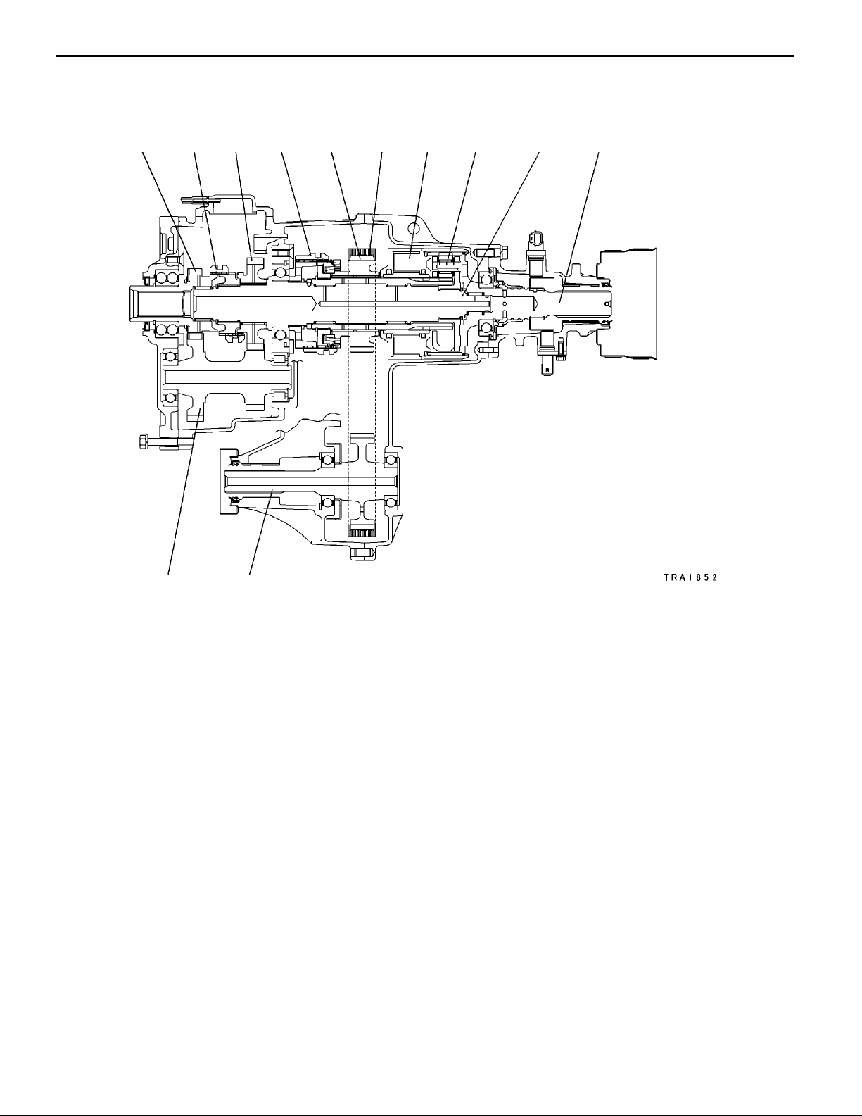
SECTIONAL VIEW <TRANSMISSION>
12345678910111213
19
18
14
17
15
16
1. Torque converter clutch
2. Torque converter
3. Oil pump
4. Overdrive clutch
5. Reverse clutch
6. Overdrive planetary carrier
7. Second brake
8. Output planetary carrier
9. Low/reverse brake
10. One-way clutch
E
Mar. 2000Mitsubishi Motors Corporation
11. Center support
12. Underdrive clutch
13. Output shaft support
14. Parking gear
15. Output shaft
16. One-way clutch
17. Direct clutch
18. Valve body
19. Input shaft
AddedPWEE8920-I
Page 4
23E-0-4
V5A51 -
SECTIONAL VIEW <TRANSFER>
1 2 3 4 5 6 7 8 9 10
General Information
12
1. Transfer input gear
2. H-L clutch
3. Low speed gear
4. 2-4WD clutch sleeve
5. Drive sprocket
6. Chain
11
7. Viscous coupling
8. Center differential planetary carrier
9. Transfer drive shaft
10. Rear output shaft
11. Front output shaft
12. Counter shaft gear
E
Mar. 2000Mitsubishi Motors Corporation
AddedPWEE8920-I
Page 5
V5A51 -
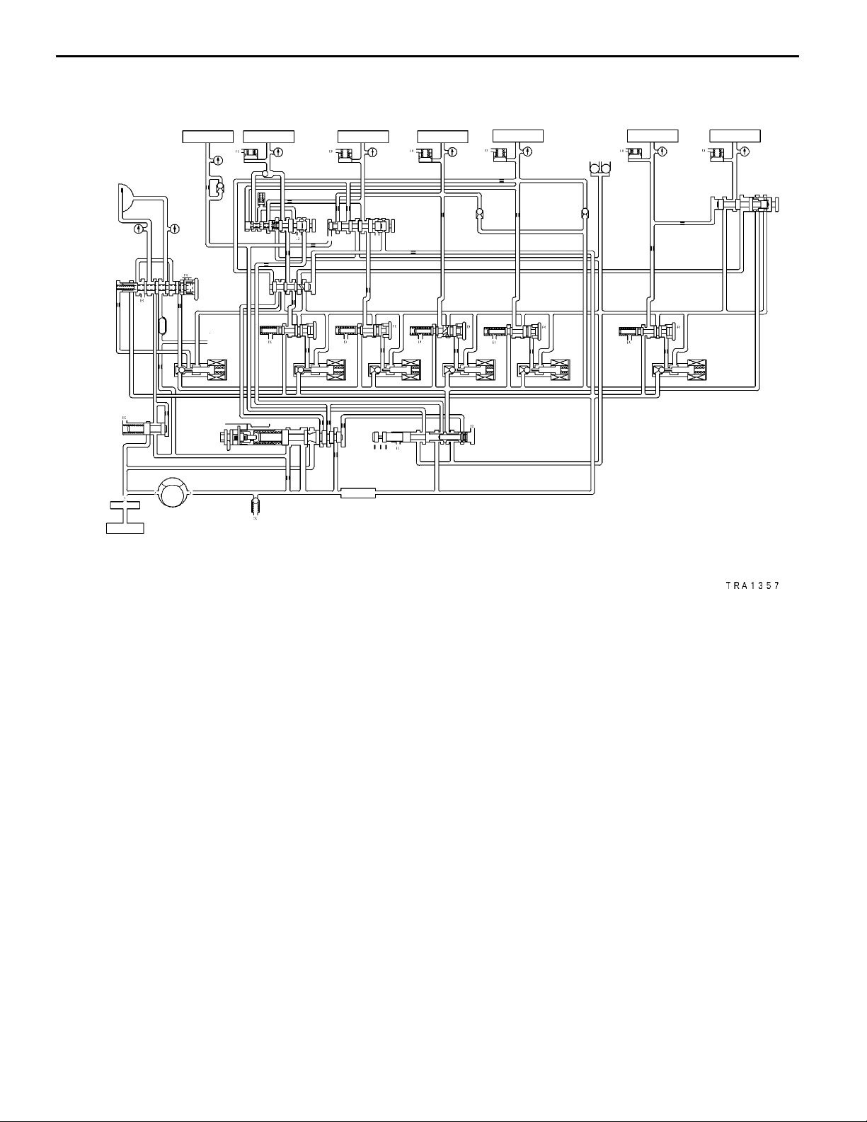
HYDRAULIC CONTROL SYSTEM
General Information
23E-0-5
25
24
21
12 3 4 5
28
6
7
9
10
8
29
30
11
22
16
12
13
14
17 18
19
23
15
20
31
32
26
27
1. Reverse clutch
2. Low/reverse brake
3. Second brake
4. Underdrive clutch
5. Overdrive clutch
6. Torque converter clutch
7. Fail-safe valve A
8. Fail-safe valve B
9. Torque converter clutch control valve
10. Switching valve
11. Cooler
12. Low-reverse brake pressure control
valve
13. Second brake pressure control valve
14. Underdrive clutch pressure control
valve
15. Overdrive clutch pressure control
valve
16. Torque converter clutch control solenoid valve
17. Low-reverse brake solenoid valve
18. Second brake solenoid valve
19. Underdrive clutch solenoid valve
20. Overdrive clutch solenoid valve
21. Torque converter pressure control
valve
22. Regulator valve
23. Manual valve
24. Oil filter
25. Oil pan
26. Oil pump
27. Oil strainer
28. Reduction brake
29. Direct clutch
30. Fail-safe valve C
31. Reduction brake pressure control
valve
32. Reduction brake solenoid valve
E
Mar. 2000Mitsubishi Motors Corporation
AddedPWEE8920-I
Page 6
V5A51 -
Specifications
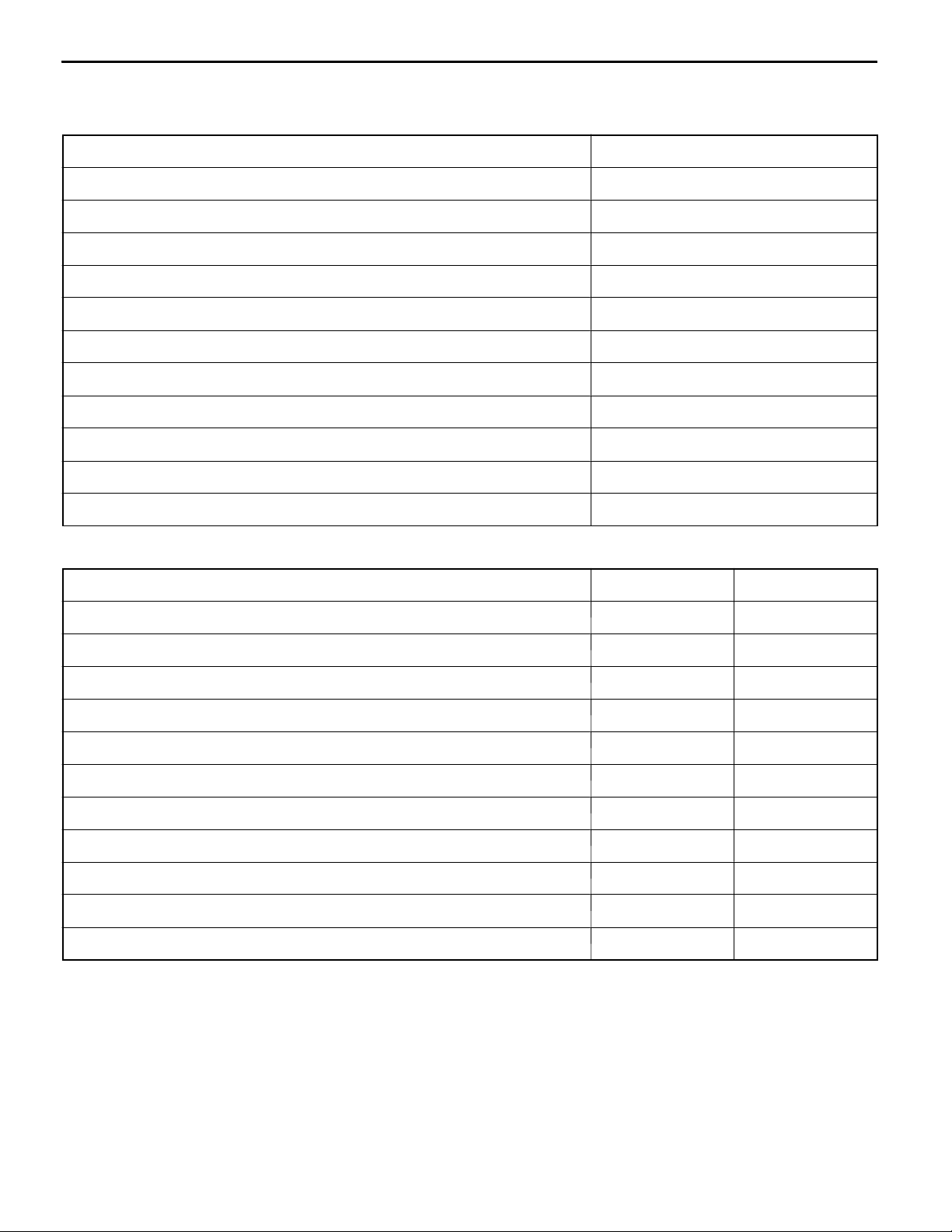
1. SPECIFICATIONS
TRANSMISSION MODEL TABLE - MODEL 2001
Transmission models Vehicle model Engine model
EUR V5A51-7-ACA V65W, V75W 6G74
V5A51-7-SDA V68W, V78W 4M41
EXP V5A51-7-CCA1 V75W 6G74
V5A51-7-CCA2 V65W, V75W 6G74
V5A51-7-SDA1 V78W 4M41
23E-1-1
E
Mar. 2000Mitsubishi Motors Corporation
AddedPWEE8920-I
Page 7
23E-1-2
V5A51 -
Specifications
GENERAL SPECIFICATIONS
Item V5A51
Torque converter Type 3-element, with torque converter clutch
Transmission Type 5-speed, fully automatic
Gear ratio 1st 3.789
2nd 2.057
3rd 1.421
4th 1.000
5th 0.731
Reverse 3.865
Transfer Type 2-speed constant mesh
Gear ratio High 1.000
Low
1.900
E
Mar. 2000Mitsubishi Motors Corporation
AddedPWEE8920-I
Page 8
V5A51 -
Specifications
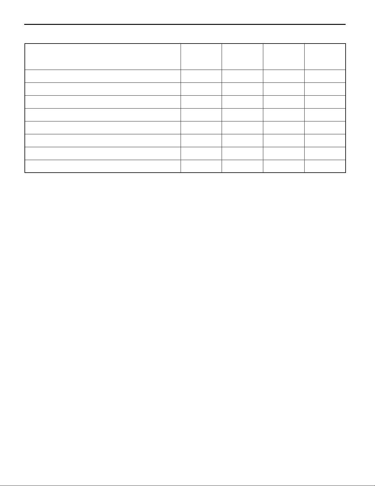
SERVICE SPECIFICATIONS
TRANSMISSION
Item Standard value
Direct planetary carrier mm 0.25 - 0.55
Underdrive clutch end play mm 1.6 - 1.8
Input shaft end play mm 0.25 - 0.81
Direct clutch end play mm 1.0 - 1.2
Overdrive clutch end play mm 2.0 - 2.2
Overdrive clutch return spring retainer end play mm 0 - 0.09
Second brake end play mm 1.49 - 1.95
Center support end play mm 0 - 0.16
Brake reaction plate end play mm 0 - 0.16
Reverse clutch end play mm 1.5 - 1.7
23E-1-3
Low/reverse brake end play mm 1.65 - 2.11
TRANSFER
Item Standard value Limit
Input gear bearing end play mm 0 - 0.06 -
Countershaft gear end play mm 0 - 0.15 -
Countershaft gear bearing end play mm 0 - 0.08 -
2-4WD clutch hub end play mm 0 - 0.08 -
H-L clutch hub end play mm 0 - 0.08 -
Rear output shaft preload mm 0.12 - 0.24 -
Rear output shaft end play mm 0 - 0.12 -
Rear output shaft bearing end play mm 0 - 0.08 -
Rear output shaft annulus gear end play mm 0 - 0.08 -
Differential lock hub end play mm 0 - 0.08 -
Clearance between outer synchronizer ring and drive sprocket mm - 0.3
E
Mar. 2000Mitsubishi Motors Corporation
AddedPWEE8920-I
Page 9
23E-1-4
V5A51 -
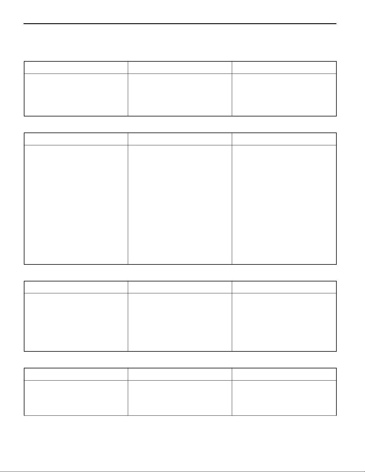
VALVE BODY SPRING IDENTIFICATION
Specifications
Item Wire
diameter
mm
Orifice check ball spring 0.5 4.5 15.4 15
Torque converter clutch control valve spring 0.7 5.9 28.1 19
Damping valve spring 1.0 7.7 35.8 17
Torque converter pressure control valve spring 1.6 11.2 29.4 9.5
Fail-safe valve A spring 0.7 8.9 21.9 9.5
Pressure control valve spring 0.7 7.6 37.7 25
Line relief valve spring 1.0 7.0 17.3 10
Regulator valve spring 1.3 13.3 44.6 10.5
Outside
diameter
mm
Free
height
mm
Number of
loops
E
Mar. 2000Mitsubishi Motors Corporation
AddedPWEE8920-I
Page 10

V5A51 -
Specifications
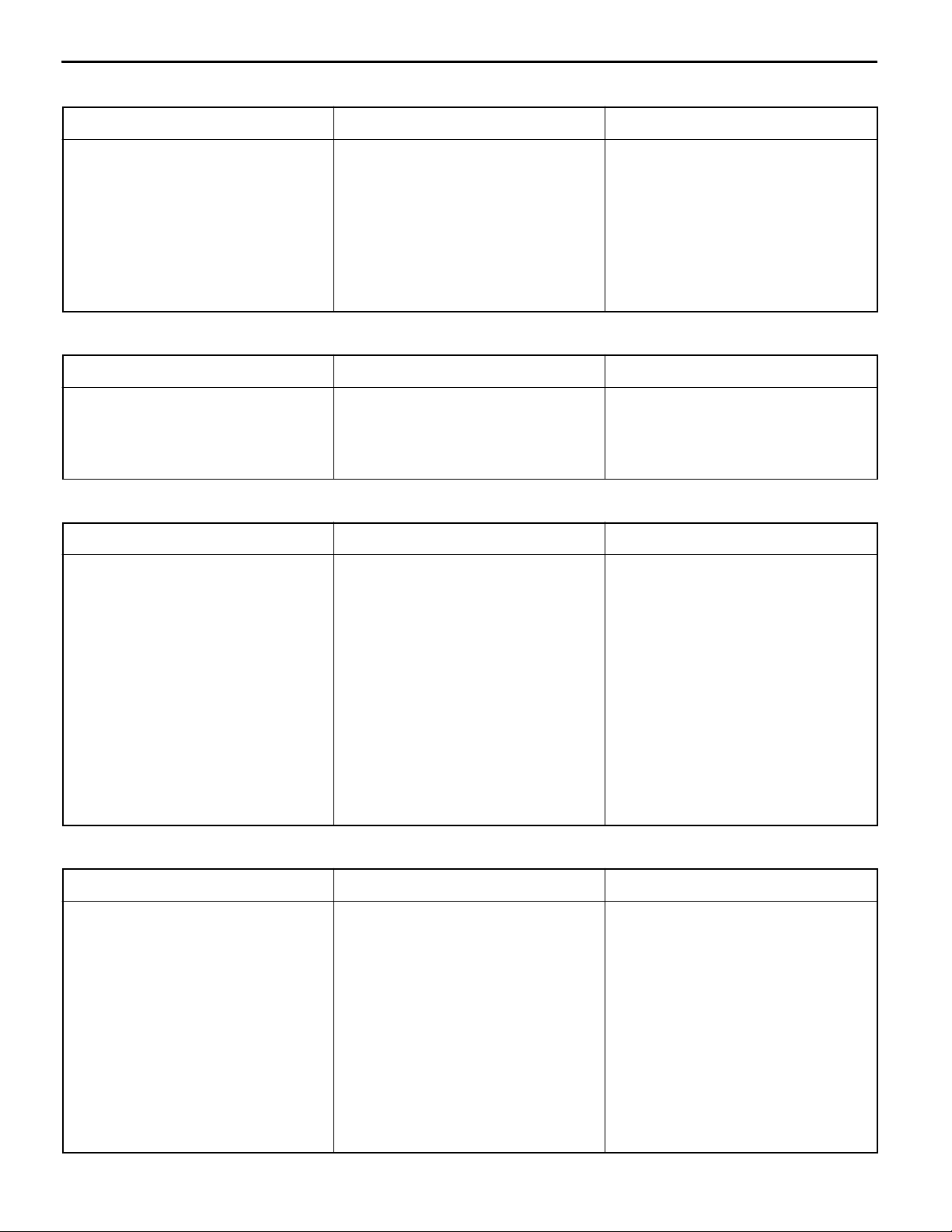
TORQUE SPECIFICATIONS
TRANSMISSION
Item Torque Nm
Output shaft support mounting bolt 23 ± 3
Upper valve body mounting bolt 11 ± 1
Park/neutral position switch mounting bolt 11 ± 1
Anchor plug 98 ± 15
Oil pan mounting bolt 11 ± 1
Oil filter mounting bolt 6 ± 1
Oil pump mounting bolt 23 ± 3
Cable end bracket mounting bolt 48 ± 6
Converter housing to transmission case tightening bolt 48 ± 6
Output shaft speed sensor mounting bolt 11 ± 1
23E-1-5
Reduction brake piston nut 19 ± 3
Separating plate mounting bolt 6 ± 1
Solenoid support mounting bolt 6 ± 1
Transfer to transfer case adapter tightening bolt 35 ± 6
Transmission case to transfer case adapter tightening bolt 48 ± 6
Input shaft speed sensor mounting bolt 11 ± 1
V alve body mounting bolt 11 ± 1
Detent spring mounting bolt 6 ± 1
Manual control lever mounting nut 22 ± 3
Lower valve body mounting bolt 11 ± 1
Lower valve body cover mounting bolt 11 ± 1
E
Mar. 2000Mitsubishi Motors Corporation
AddedPWEE8920-I
Page 11

23E-1-6
V5A51 -
Specifications
TRANSFER
Item Torque Nm
Dynamic damper 35 ± 6
Transfer case cover tightening bolt 19 ± 2
Input gear bearing retainer mounting bolt 20 ± 2
Transfer case to chain cover tightening bolt 35 ± 6
Rear bearing retainer mounting bolt 20 ± 2
Transfer case plate to transfer case tightening bolt and nut 35 ± 6
Rear cover to chain cover tightening bolt 35 ± 6
Shift actuator mounting bolt 11 ± 1
4LLC switch 35 ± 6
2WD switch 35 ± 6
Center differential lock switch 35 ± 6
4H switch 35 ± 6
2WD-4WD switch 35 ± 6
Vehicle speed sensor mounting bolt 11 ± 1
Front outoput sensor mounting bolt 11 ± 1
Rear output sensor mounting bolt 11 ± 1
E
Mar. 2000Mitsubishi Motors Corporation
AddedPWEE8920-I
Page 12
V5A51 -
Specifications
23E-1-7
SNAP RING, THRUST RACE, SPACER AND PRESSURE PLATE FOR ADJUSTMENT
TRANSMISSION
Thrust race (for adjustment of direct planetary carrier end play)
Thickness mm Identification symbol Part number
1.6
1.8
2.0
2.2
2.3
None
None
None
None
None
MR276705
MR276706
MR276707
MR276708
MR276709
Snap ring (for adjustment of underdrive clutch and overdrive clutch end play)
Thickness mm Identification symbol Part number
1.6
1.7
1.8
1.9
2.0
2.1
2.2
2.3
2.4
2.5
2.6
2.7
2.8
2.9
3.0
Brown
None
Blue
Brown
None
Blue
Brown
None
Blue
Brown
None
Blue
Brown
None
Blue
MD759960
MD759961
MD759962
MD758892
MD750841
MD750842
MD750843
MD750844
MD750845
MD750846
MD750847
MD750848
MD750849
MD750850
MD750851
Thrust race (for adjustment of input shaft end play)
Thickness mm Identification symbol Part number
1.4
1.6
1.8
2.0
2.2
2.4
2.6
None
None
None
None
None
None
None
MD723063
MD707267
MD723064
MD707268
MD723065
MD724358
MD754798
Snap ring (for adjustment of overdrive clutch return spring retainer end play)
Thickness mm Identification symbol Part number
1.48
1.53
1.58
1.63
Brown
Black
None
Brown
MR336158
MR336159
MR336160
MR336161
E
Mar. 2000Mitsubishi Motors Corporation
AddedPWEE8920-I
Page 13
23E-1-8
V5A51 -
Specifications
Pressure plate (for adjustment of second brake end play)
Thickness mm Identification symbol Part number
1.6
1.8
2.0
2.2
2.4
2.6
2.8
3.0
F
E
D
C
B
A
0
1
MR336390
MR336391
MR336392
MR336393
MR336394
MR336395
MR336396
MR336397
Snap ring (for adjustment of center support and brake reaction plate end play)
Thickness mm Identification symbol Part number
2.2
2.3
2.4
2.5
None
Blue
Brown
None
MD756784
MD756785
MD758552
MD758553
Snap ring (for adjustment of reverse clutch end play)
Thickness mm Identification symbol Part number
1.6
1.7
1.8
1.9
2.0
2.1
2.2
2.3
2.4
2.5
2.6
2.7
2.8
None
Blue
Brown
None
Blue
Brown
None
Blue
Brown
None
Blue
Brown
None
MD761088
MD761089
MD761090
MD758947
MD756690
MD756691
MD756692
MD756693
MD756694
MD756695
MD756696
MD756697
MD756698
Snap ring (for adjustment of direct clutch end play)
Thickness mm Identification symbol Part number
1.9
2.0
2.1
2.2
2.3
2.4
2.5
2.6
2.7
2.8
2.9
3.0
E
Mar. 2000Mitsubishi Motors Corporation
Brown
None
Blue
Brown
None
Blue
Brown
None
Blue
Brown
None
Blue
MD758946
MD753397
MD753398
MD753399
MD753400
MD753401
MD753402
MD753403
MD753404
MD753405
MD753406
MD753497
AddedPWEE8920-I
Page 14
V5A51 -
Specifications
Snap ring (for adjustment of low/reverse brake end play)
Thickness mm Identification symbol Part number
23E-1-9
1.8
2.0
2.2
2.4
2.6
2.8
3.0
E
D
C
B
A
0
1
MD759425
MD759426
MD759427
MD759428
MD759429
MD759430
MD759431
TRANSFER
Spacer (for adjustment of input gear bearing end play)
Thickness mm Identification symbol Part number
2.30
2.35
2.40
2.45
2.50
None
Red
White
Blue
Green
MD704199
MD704200
MD704201
MD704202
MD704203
Spacer (for adjustment of countershaft gear end play)
Thickness mm Identification symbol Part number
1.77
1.91
2.05
2.19
2.33
None
Blue
Brown
White
Red
MB896728
MB896729
MB896730
MB896731
MB896732
Snap ring (for adjustment of countershaft gear bearing end play)
Thickness mm Identification symbol Part number
1.48
1.62
Blue
None
MB919176
MB919177
Snap ring (for adjustment of H-L clutch hub end play)
Thickness mm Identification symbol Part number
2.18
2.25
2.32
2.39
None
None
None
None
MR410928
MR410929
MR410930
MR410931
E
Mar. 2000Mitsubishi Motors Corporation
AddedPWEE8920-I
Page 15
23E-1-10
V5A51 -
Specifications
Snap ring (for adjustment of differential lock hub end play)
Thickness mm Identification symbol Part number
2.56
2.63
2.70
2.77
2.84
2.91
2.98
None
Red
White
Blue
Yellow
Green
Brown
MD738386
MD738387
MD738388
MD738389
MD738390
MD738391
MD738392
Snap ring (for adjustment of 2-4WD clutch hub end play)
Thickness mm Identification symbol Part number
2.56
2.63
2.70
2.77
2.84
None
Red
White
Blue
Yellow
MD738393
MD738394
MD738395
MD738396
MD738397
Snap ring (for adjustment of rear output shaft bearing end play)
Thickness mm Identification symbol Part number
2.26
2.33
2.40
2.47
None
Red
White
Blue
MD73431 1
MD734312
MD734313
MD734314
Snap ring (for adjustment of rear output shaft annulus gear end play)
Thickness mm Identification symbol Part number
1.90
1.94
1.98
2.02
2.06
2.10
None
None
None
None
None
None
MR305024
MR305025
MR305026
MR305027
MR305028
MR305029
E
Mar. 2000Mitsubishi Motors Corporation
AddedPWEE8920-I
Page 16
V5A51 -
Specifications
Snap ring (for adjustment of rear output shaft preload)
Thickness mm Identification symbol Part number
23E-1-11
1.57
1.63
1.69
1.75
1.81
1.87
1.93
1.99
2.05
2.11
2.17
2.23
2.29
2.35
2.41
2.47
2.53
2.59
2.65
2.71
None
None
None
None
None
None
None
None
None
None
None
None
None
None
None
None
None
None
None
None
Spacer (for adjustment of rear output shaft end play)
MR486340
MR486341
MR486342
MR486343
MR486344
MR486345
MR486346
MR486347
MR477935
MR477936
MR477937
MR477938
MR477939
MR477940
MR477941
MR477942
MR477943
MR477944
MR477945
MR477946
Thickness mm Identification symbol Part number
2.57
2.63
2.69
2.75
2.81
2.87
2.93
2.99
3.05
3.11
3.17
3.23
3.29
3.35
3.41
3.47
3.53
3.59
3.65
3.71
3.77
3.83
3.89
3.95
None
None
None
None
None
None
None
None
None
None
None
None
None
None
None
None
None
None
None
None
None
None
None
None
MR477950
MR477951
MR477952
MR477953
MR477954
MR477955
MR477956
MR477957
MR477958
MR477959
MR477960
MR477961
MR477962
MR477963
MR477964
MR477965
MR477966
MR477967
MR477968
MR486348
MR486349
MR486350
MR486351
MR486352
E
Mar. 2000Mitsubishi Motors Corporation
AddedPWEE8920-I
Page 17

23E-1-12
V5A51 -
Specifications
SEALANTS
TRANSMISSION
Item Specified sealant
Oil pan MITSUBISHI genuine sealant part No. MR166584 or
equivalent
Transfer case adapter (transmission side) MITSUBISHI genuine sealant part No. MR166584 or
equivalent
TRANSFER
Item Specified sealant
Bearing retainer mounting bolt MITSUBISHI genuine sealant part No. MD997740 or
equivalent
Chain cover MITSUBISHI genuine sealant part No. MD997740 or
equivalent
Transfer case cover MITSUBISHI genuine sealant part No. MD997740 or
equivalent
Rear cover MITSUBISHI genuine sealant part No. MD997740 or
equivalent
Sealing cap 3MTMAAD part No. 8672 or equivalent
Transfer case plate MITSUBISHI genuine sealant part No. MD997740 or
equivalent
Mar. 2000Mitsubishi Motors Corporation AddedPWEE8920-I
E
E
Mar. 2000Mitsubishi Motors Corporation
AddedPWEE8920-I
Page 18
V5A51 -
Specifications
23E-1-13
FORM-IN-PLACE GASKET (FIPG)
The transmission has several areas where the form-in-place gasket (FIPG) is in use. To ensure that
the gasket fully serves its purpose, it is necessary to observe some precautions when applying the gasket.
Bead size, continuity and location are of paramount importance. Too thin a bead could cause leaks.
Too thick a bead, on the other hand, could be squeezed out of location, causing blocking or narrowing
of the fluid feed line. To eliminate the possibility of leaks from a joint, therefore, it is absolutely necessary
to apply the gasket evenly without a break, while observing the correct bead size.
Since the FIPG used in the transmission hardens as it reacts with the moisture in the atmospheric air,
it is normally used in the metallic flange areas.
Disassembly
The parts assembled with the FIPG can be easily disassembled without use of a special method. In
some cases, however, the sealant between the joined surfaces may have broken by lightly striking with
a mallet or similar tool. A flat and thin gasket scraper may be lightly hammered in between the joined
surfaces. In this case, however, care must be taken to prevent damage to the joined surfaces.
Surface preparation
Thoroughly remove all substances deposited on the gasket application surfaces, using a gasket scraper
or wire brush. Check to ensure that the surfaces to which the FIPG is to be applied is flat. Make sure
that there are no oils, greases and foreign substances deposited on the application surfaces. Do not
forget to remove the old FIPG remaining in the bolt holes.
Form-in-place gasket application
When assembling parts with the FIPG, you must observe some precautions, but the procedures is very
simple as in the case of a conventional precut gasket.
Applied FIPG bead should be of the specified size and without breaks. Also be sure to encircle the
bolt hole circumference with a completely continuous bead. The FIPG can be wiped away unless it is
hardened. While the FIPG is still moist (in less than 15 minutes), mount the parts in position. When
the parts are mounted, make sure that the gasket is applied to the required area only. In addition, do
not apply any oil or water to the sealing locations or start the engine until a sufficient amount of time
(about one hour) has passed after installation is completed.
The FIPG application procedure may vary on different areas. Observe the procedure described in the
text when applying the FIPG.
LUBRICANTS
TRANSFER
Item Specified lubricant
Lip of transfer case oil seal MITSUBISHI genuine grease part No. 0101011 or
equivalent
Lip of transfer case plate oil seal
Lip of rear cover oil seal
E
Mar. 2000Mitsubishi Motors Corporation
AddedPWEE8920-I
Page 19
V5A51 -
Special Tools
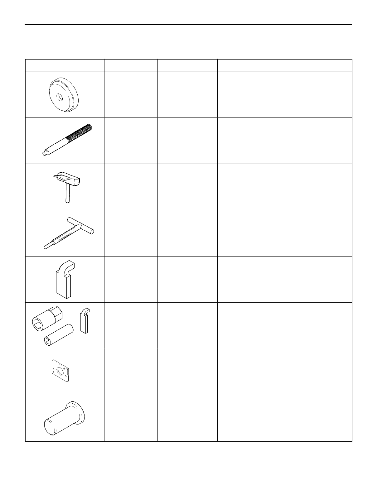
2. SPECIAL TOOLS
TRANSMISSION
Tool Number Name Use
MB990929 Installer adapter Installation of transfer case adapter oil seal
MB990938 Handle Use with installer adapter
MD998727 Oil pan remover Removal of oil pan
23E-2-1
MD998333 Oil pump remover Removal of oil pump
MB991693 Reduction brake
stopper
MB991633 Reduction brake
wrench set
MB991603 Bearing installer
stopper
Adjustment reduction brake piston
Adjustment reduction brake piston
Measurement of direct planetary carrier and
center support end plays
MD998304 Oil seal installer Measurement of direct planetary carrier end
play
E
Mar. 2000Mitsubishi Motors Corporation
AddedPWEE8920-I
Page 20
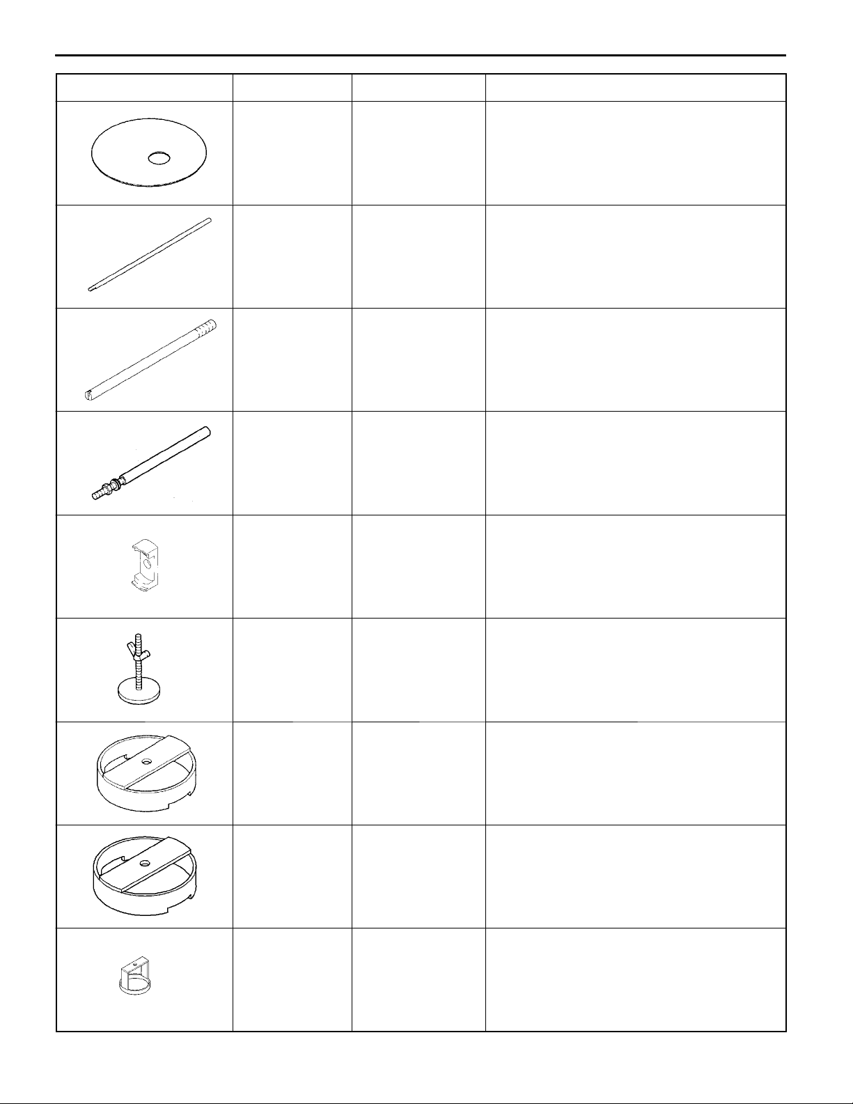
23E-2-2
Tool UseNameNumber
V5A51 -
Special Tools
MB991632 Clearance dummy
plate
MD998913 Dial gauge exten-
sion
MD998412 Guide Installation of oil pump
MD998316 Dial gauge support Measurement of input shaft end play
Measurement of brake reaction plate, second
brake and low/reverse brake end plays
Measurement of brake reaction plate, second
brake and low/reverse brake end plays
MD999590 Spring compressor Removal and installation of reverse and
overdrive clutch spring retainer snap ring
MD998924 Spring compressor
retainer
MB991629 Spring compressor Measurement of overdrive clutch and under-
MB991789 Spring compressor Adjustment reverse clutch end play
Use with spring compressor
drive clutch end plays
MB991630 Spring compressor Removal and installation of center support
snap ring and direct clutch snap ring
E
Mar. 2000Mitsubishi Motors Corporation
AddedPWEE8920-I
Page 21

Tool UseNameNumber
MD998907 Spring compressor Removal and installation of underdrive clutch
V5A51 -
Special Tools
spring retainer snap ring
23E-2-3
E
Mar. 2000Mitsubishi Motors Corporation
AddedPWEE8920-I
Page 22
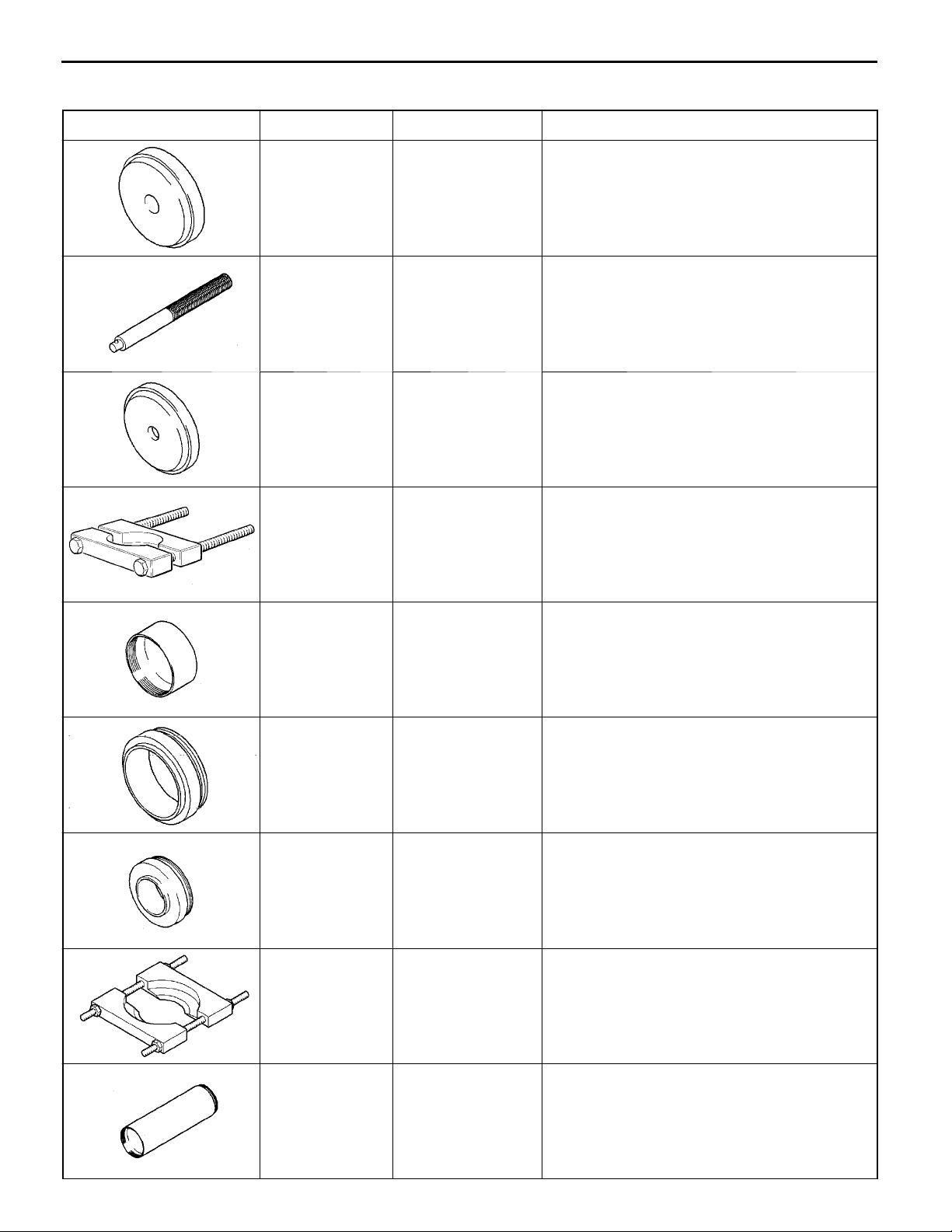
23E-2-4
V5A51 -
Special Tools
TRANSFER
Tool Number Name Use
MB990932 Installer adapter Installation of oil seal
MB990938 Handle Use with installer adapter
MB990936 Installer adapter Installation of oil seal
MD998801 Bearing remover Removal and installation of bearing
MD998812 Installer cap Use with installer and installer adapter
MD998826 Installer adapter
(52)
MD998818 Installer adapter
(38)
Installation of transfer input gear bearing
Installation of countershaft gear bearing, front
output shaft bearing
MD998917 Bearing remover Removal and installation of bearing
MD998814 Installer-200 Use with installer cap and installer adapter
E
Mar. 2000Mitsubishi Motors Corporation
AddedPWEE8920-I
Page 23
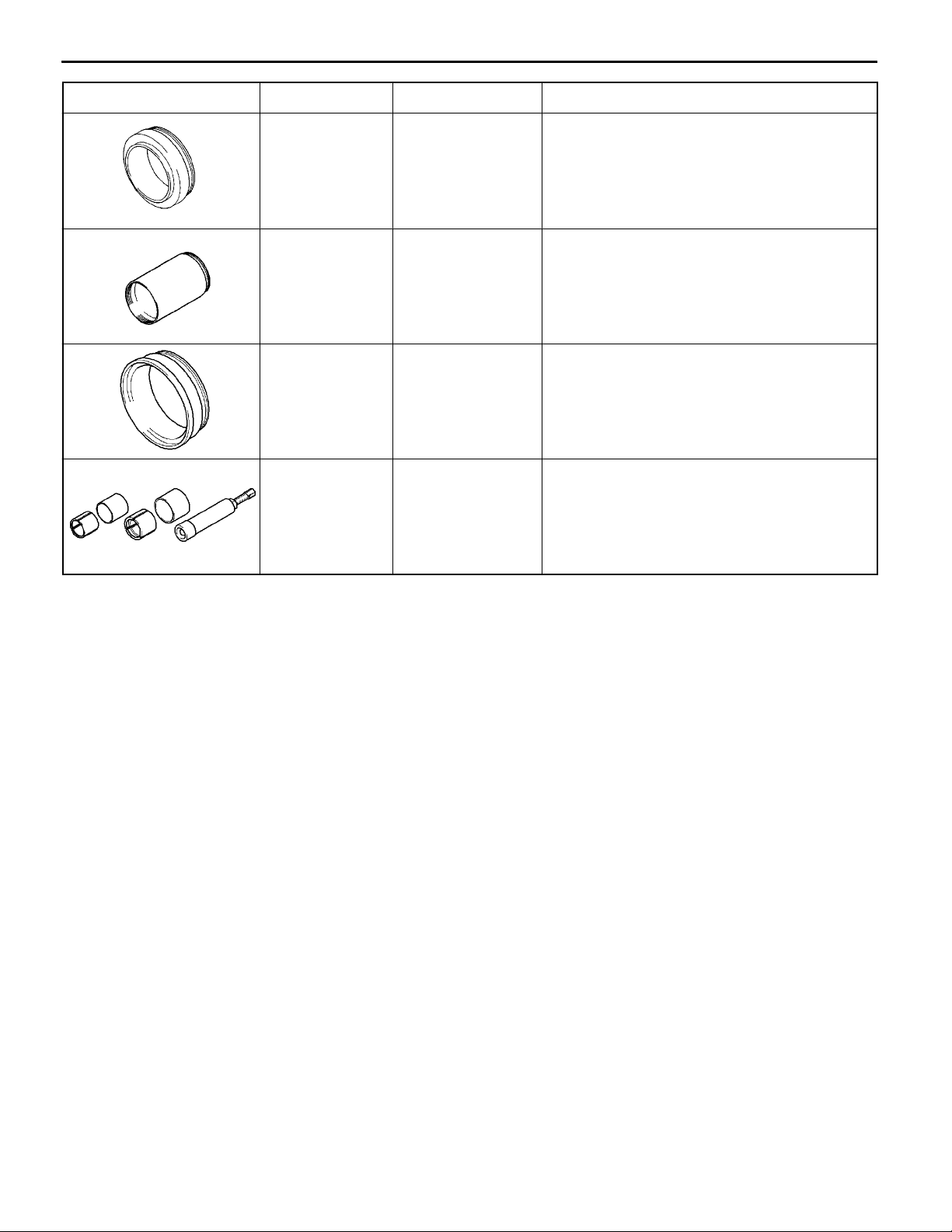
Tool UseNameNumber
V5A51 -
Special Tools
23E-2-5
MD998824 Installer adapter
(50)
MD998813 Installer-100 Use with installer cap and installer adapter
MD998830 Installer adapter
(66)
MD998192 Bearing puller Installation of transfer drive shaft bearing
Installation of rear output shaft bearing
Installation of transfer drive shaft bearing
E
Mar. 2000Mitsubishi Motors Corporation
AddedPWEE8920-I
Page 24
V5A51 -
Transmission and Transfer
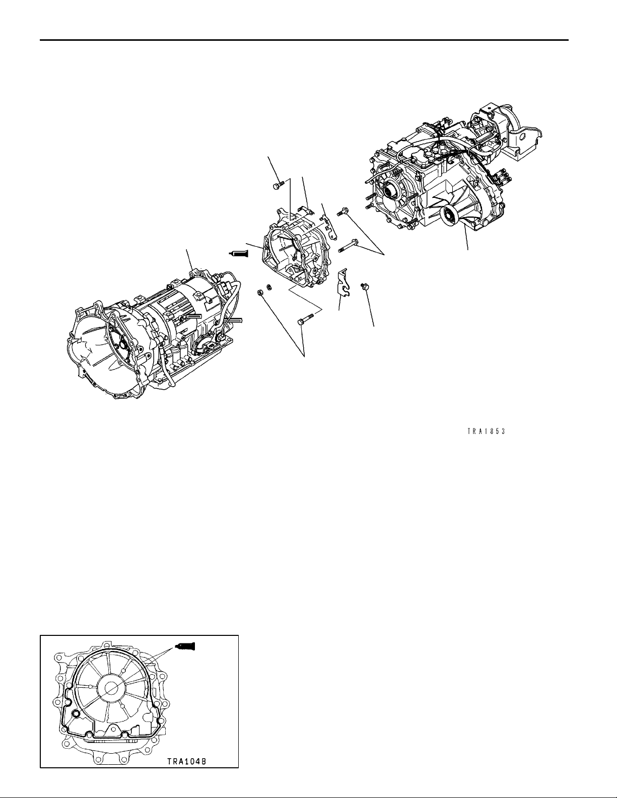
3. TRANSMISSION AND TRANSFER
DISASSEMBLY AND ASSEMBLY
35±6Nm
4
23E-3-1
3
6
Disassembly steps
1. Transfer
2. Cable end bracket
3. Harness bracket
4. Harness bracket
"AA 5. Transfer case adapter
6. Transmission
5
48±6Nm
1
2
48±6Nm
35±6Nm
ASSEMBLY SERVICE POINT
"AA
After squeezing out and applying sealant on the transfer case
3mm
diameter
adapter at the section indicated in the illustration, install onto
the transmission case.
Specified sealant:
Caution
D
E
Mar. 2000Mitsubishi Motors Corporation
TRANSFER CASE ADAPTER INSTALLATION
MITSUBISHI genuine sealant part No. MR166584 or
equivalent
Evenly squeeze out and apply the sealant so that
it is not excessive and does not ooze out.
AddedPWEE8920-I
Page 25
V5A51 -
Transfer Case Adapter
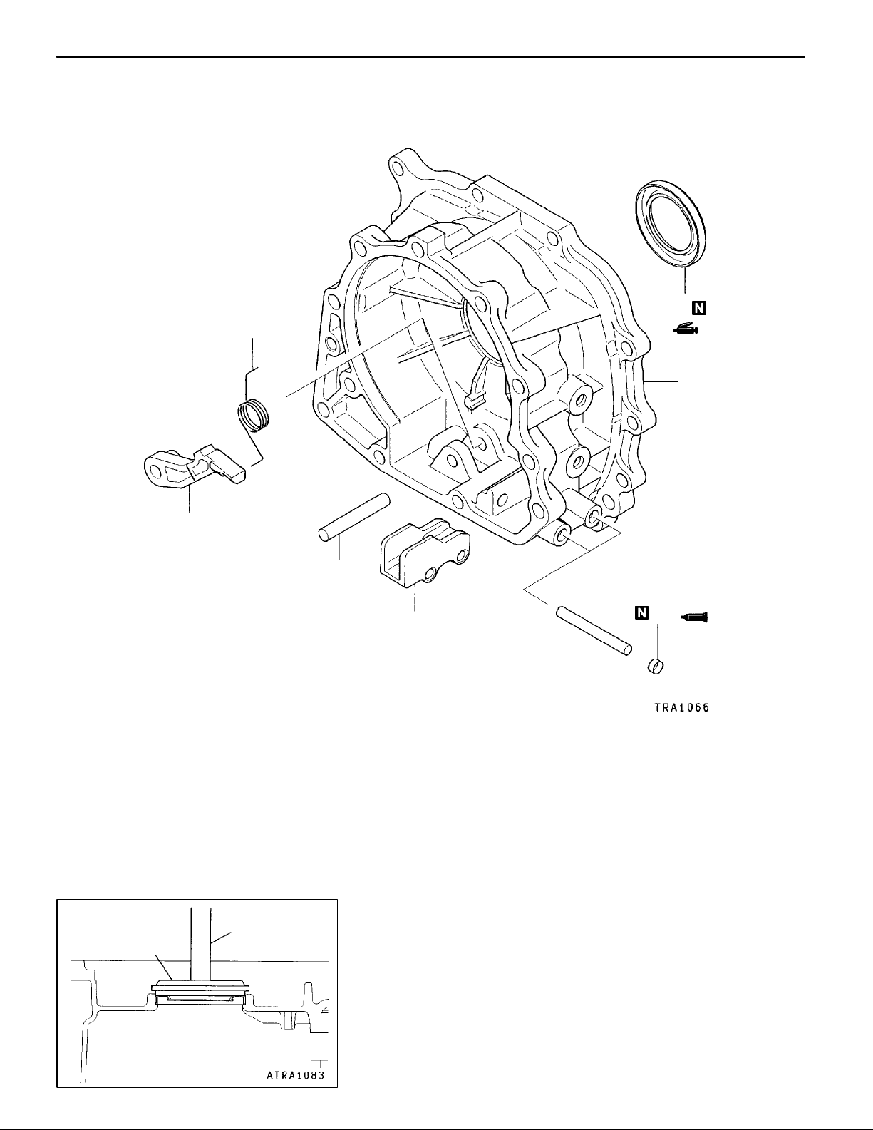
4. TRANSFER CASE ADAPTER
DISASSEMBLY AND ASSEMBLY
2
23E-4-1
7
8
3
Disassembly steps
1. Parking sprag shaft
"CA 2. Parking sprag spring
3. Parking sprag
"BA 4. Sealing cap
5. Parking roller support shaft
6. Parking roller support
"AA 7. Oil seal
8. Transfer case adapter
MB990938
MB990929
1
6
ASSEMBLY SERVICE POINTS
"AA
Use the special tools to install the oil seal.
OIL SEAL INSTALLATION
5
4
E
Mar. 2000Mitsubishi Motors Corporation
AddedPWEE8920-I
Page 26
23E-4-2
V5A51 -
Transfer Case Adapter
Sealing cap
1.5 mm
1.5 mm
"BA
SEALING CAP INSTALLATION
1. Press the sealing caps into the dimensions shown in
the illustration so that they are not slanted.
2. Apply sealant as shown in the illustration.
Specified sealant:
TM
"CA
3M
PARKING SPRAG SPRING INSTALLATION
AAD part No. 8672 or equivalent
Attach the end of the spring to the position shown in the
illustration.
E
Mar. 2000Mitsubishi Motors Corporation
AddedPWEE8920-I
Page 27
V5A51 -
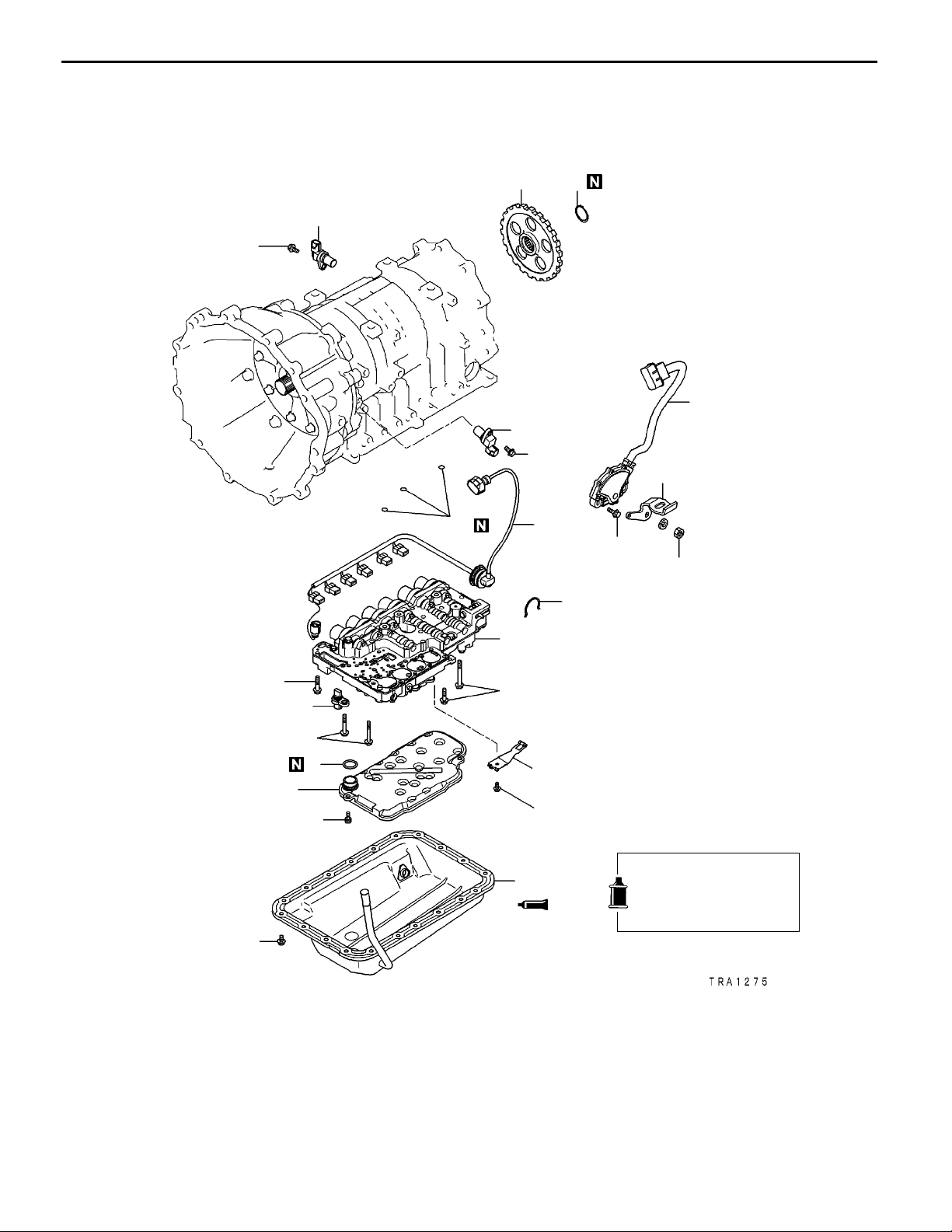
5. TRANSMISSION
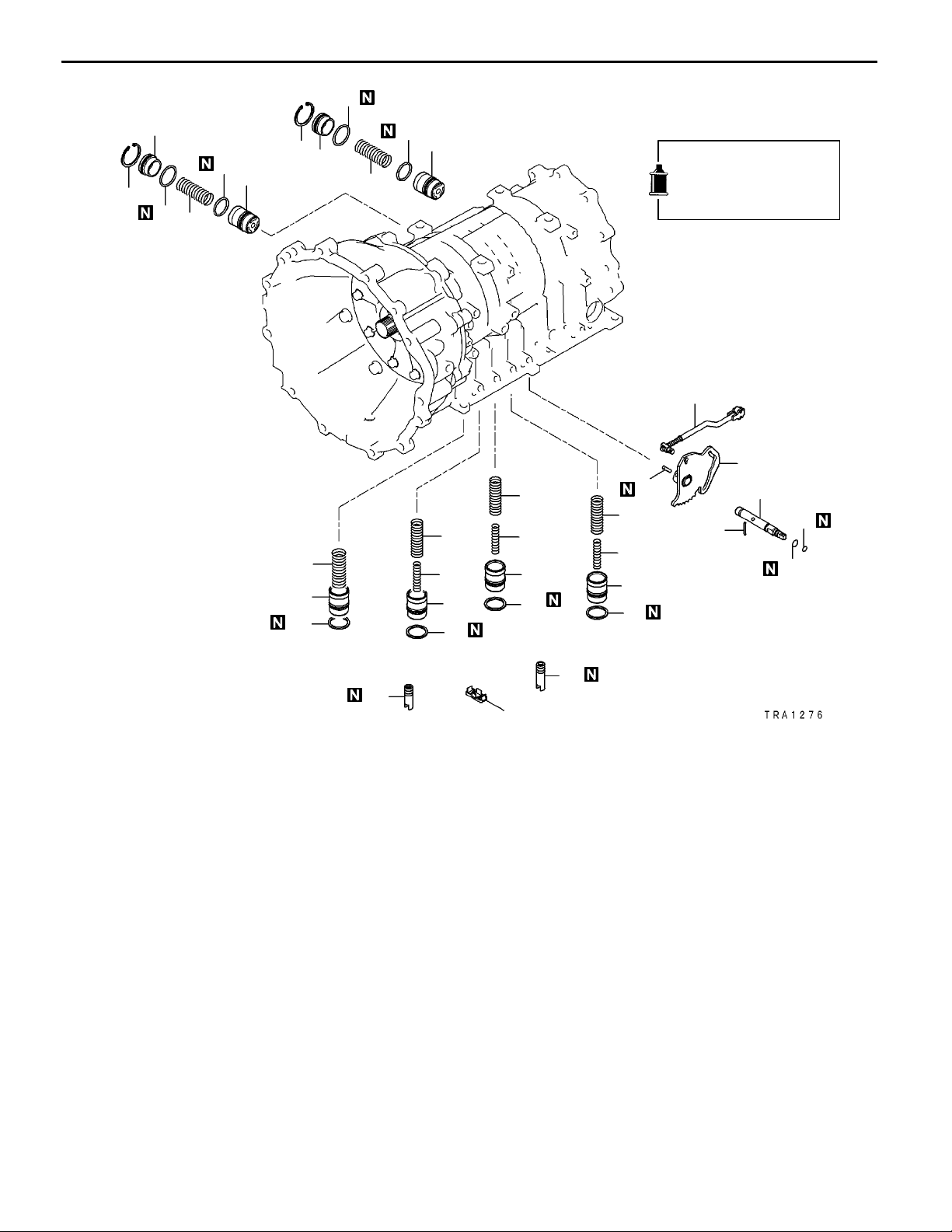
DISASSEMBLY AND ASSEMBLY
Transmission
23E-5-1
11±1Nm
6
5
2
4
1
11±1Nm
3
13
15
11±1Nm
22±3Nm
14
11±1Nm
11
11±1Nm
9
8
6±1Nm
11±1Nm
1. Input shaft speed sensor
2. Output shaft speed sensor
3. Manual control lever
4. Park/neutral position switch
5. Snap ring
6. Parking gear
7. Oil pan
8. Oil filter
12
11±1Nm
10
6±1Nm
7
Apply automatic
transmission fluid to
all moving parts
before installation.
9. O-ring
10. Detent spring
11. Oil temperature sensor
12. Valve body
13. O-ring
14. Snap ring
15. Solenoid valve harness
E
Mar. 2000Mitsubishi Motors Corporation
AddedPWEE8920-I
Page 28
23E-5-2
V5A51 -
33
Transmission
31
32
33
34
37
36
31
21
20
19
32
34
37
35
27
24
26
23 25
22
19
19
30
29
28
19
Apply automatic
transmission fluid to
all moving parts
before installation.
44
38
39
43
40
41
42
16. Oil seal
17. Oil seal
18. Oil strainer
19. Seal ring
20. Accumulator piston
(for overdrive clutch)
21. Accumulator spring
22. Accumulator piston
(for second brake)
23. Inner spring
24. Outer spring
25. Accumulator piston
(for low/reverse brake)
26. Inner spring
27. Outer spring
28. Accumulator piston
(for underdrive clutch)
29. Inner spring
17
16
18
30. Outer spring
31. Snap ring
32. Accumulator cover
33. O-ring
34. Accumulator spring
35. Accumulator piston
(for reduction brake)
36. Accumulator piston
(for direct clutch)
37. Seal ring
38. Spring pin
39. Pin
40. Manual control shaft
41. O-ring
42. O-ring
43. Detent lever
44. Parking roller rod
E
Mar. 2000Mitsubishi Motors Corporation
AddedPWEE8920-I
Page 29
48±6Nm
45
23±3Nm
V5A51 -
46
Transmission
47
23E-5-3
52
50
51
48
49
45. Converter housing
46. Oil pump
47. Oil pump gasket
48. Thrust race No.1
49. Thrust bearing No.2
50. Reverse and overdrive clutch
51. Thrust bearing No.3
53
57
56
55
54
Apply automatic
transmission fluid to
all moving parts
before installation.
52. Overdrive clutch hub
53. Thrust bearing No.4
54. Reverse sun gear
55. Snap ring
56. Second brake
57. Return spring
E
Mar. 2000Mitsubishi Motors Corporation
AddedPWEE8920-I
Page 30
23E-5-4
V5A51 -
Transmission
58
60
65
59
66
61
62
64
63
68
69
Apply automatic
transmission fluid to
all moving parts
before installation.
67
58. Pressure plate
59. Brake plate
60. Brake disc
61. Low/reverse annulus gear
62. Thrust bearing No.7
63. Snap ring
E
Mar. 2000Mitsubishi Motors Corporation
64. Reaction plate
65. Snap ring
66. Brake plate
67. Brake disc
68. Pressure plate
69. Wave spring
AddedPWEE8920-I
Page 31

Apply automatic
transmission fluid to
all moving parts
before installation.
V5A51 -
74
75
Transmission
98±15 Nm
91
94
23E-5-5
23±3Nm
70
77
71
72
76
73
78
88
89
90
95
92
85
19±3Nm
82
93
87
86
84
83
81
80
79
70. Snap ring
71. Center support
72. Thrust race No.8
73. Thrust bearing No.9
74. Direct annulus gear
75. Thrust bearing No.12
76. Direct planetary carrier
77. Seal ring
78. Seal ring
79. Snap ring
80. Reduction brake cover
81. O-ring
82. Snap ring
83. Reduction brake piston nut
84. Reduction brake piston
85. Seal ring
86. Reduction brake piston adjusting rod
87. Reduction brake spring
88. Direct clutch
89. Thrust bearing No.13
90. Reduction brake band
91. Anchor plug
92. O-ring
93. Output shaft support
94. Output shaft support gasket
95. Transmission case
E
Mar. 2000Mitsubishi Motors Corporation
AddedPWEE8920-I
Page 32

23E-5-6
V5A51 -
DISASSEMBLY
Caution
D
D
D
D
D
Transmission
Because the automatic transmission is manufactured
from high-precision parts, sufficient care must be
taken not to scratch or damage these parts during
disassembly and reassembly.
During the work, always use bare hands or vinyl
gloves. Do not use cotton gloves. Use nylon cloth
or paper towels when necessary. Do not use shop
towel.
Parts which have been disassembled should all be
cleaned. Metal parts can be cleaned with normal
detergent, but they should be dried completely using
compressed air.
Clutch discs, plastic thrust race and rubber parts
should be cleaned with ATF automatic transmission
fluid so that they do not become dirty.
If the transmission body has been damaged,
disassemble and clean the cooler system also.
Manual control lever
1. Remove the input shaft speed sensor.
2. Remove the output shaft speed sensor.
3. Remove the manual control lever, and then remove the
park/neutral position switch.
Park/neutral position
switch
E
Mar. 2000Mitsubishi Motors Corporation
AddedPWEE8920-I
Page 33

Snap ring
Parking gear
MD998727
V5A51 -
4. Remove the snap ring, and remove the parking gear
5. Remove the twenty oil pan mounting bolts and then
Transmission
23E-5-7
using a puller (corresponding load approximately 9,800
N).
NOTE
The parking gear may be removed without using a puller.
remove the oil p an using the special tool.
Caution
D
Carefully hammer the special tool so that the oil
pan mounting surface is not damaged.
O-ring
Oil filter
6. Remove the oil filter and O-ring.
7. Remove the detent spring.
8. Disconnect the harness connectors of the valve body.
E
Mar. 2000Mitsubishi Motors Corporation
AddedPWEE8920-I
Page 34

23E-5-8
Oil temperature
sensor
O-rings
V5A51 -
9. Remove the twenty valve body mounting bolts a n d then
Transmission
remove the valve body, three O-rings and oil temperature
sensor.
NOTE
The twenty valve body mounting bolts are plated bolts.
NOTE
The O-rings are mounted on the transmission case side
as shown in the illustration. However there may be cases
where they will come off with the valve body.
Oil seals
Oil strainer
Snap ring
10. Remove the snap ring and disconnect the solenoid valve
harness.
11. Remove the oil strainer and two oil seals.
12. Remove each accumulator piston, seal ring and spring.
Remove the snap ring, then remove the accumulator
cover, O-ring and spring.
No. Name
1 For overdrive clutch
2 For second brake
3 For low/reverse brake
4 For underdrive clutch
5 For reduction brake
1234
E
Mar. 2000Mitsubishi Motors Corporation
6 For direct clutch
AddedPWEE8920-I
Page 35

V5A51 -
Transmission
23E-5-9
NOTE
To make assembly easier, attach an identification tag
on the removed accumulator piston.
6
Spring pin
Parking
roller rod
5
Pin
Manual
control shaft
Detent
lever
13. Remove the detent lever spring pin.
14. Remove the pin, and then remove the manual control
shaft, two O-rings, detent lever an d parking roller rod.
15. Remove the eight converter housing mounting bolts, an d
then converter housing.
16. Remove the te n oil pump mounting bolts.
17. Install the special tool into the bolt hole shown in the
illustration.
E
Mar. 2000Mitsubishi Motors Corporation
AddedPWEE8920-I
Page 36

23E-5-10
MD998333
V5A51 -
18. While screwing in the special tool evenly, remove the
19. Remove the oil pump gasket.
Transmission
oil pump.
Thrust
bearing
No.2
Reverse and overdrive
clutch
Overdrive
clutch hub
Thrust race
No.1
Thrust
bearing No.3
20. Remove t he reverse a nd overdrive clutch, thrust race
No.1 an d thrust bearing No.2.
NOTE
The thrust race No.1 may be attached to the oil pump.
21. Remove the overdrive clutch hub and thrust bearing No.3.
22. Remove the thrust bearing No.4.
NOTE
The thrust bearing No.4 may be attached to the overdrive
clutch hub.
23. Remove the reverse sun gear.
E
Mar. 2000Mitsubishi Motors Corporation
AddedPWEE8920-I
Page 37

V5A51 -
24. Remove the snap ring.
25. Remove the second brake an d return spring.
Transmission
23E-5-11
Thrust
bearing
No.7
26. Remove the pressure plate, brake plates and brake discs.
27. Remove the low/reverse annulus gear.
28. Remove the thrust bearing No.7.
NOTE
The thrust bearing No.7 may be attached to the
low/reverse annulus gear.
E
Mar. 2000Mitsubishi Motors Corporation
AddedPWEE8920-I
Page 38

23E-5-12
V5A51 -
29. Remove the snap ring.
30. Remove the reaction plate and one brake disc.
Transmission
31. Remove the snap ring.
32. Remove the brake plates, brake discs, and pressure plate.
33. Remove the wave spring.
E
Mar. 2000Mitsubishi Motors Corporation
AddedPWEE8920-I
Page 39

Snap ring
Center support
V5A51 -
34. Remove the snap ring and center support.
Transmission
23E-5-13
Thrust bearing
No.9
Direct planetary
carrier
35. Remove the thrust race No.8 and thrust bearing No.9.
NOTE
The thrust race No.8 may be attached to the center
support.
Thrust race
No.8
36. Remove the direct annulus gear.
37. Remove the thrust bearing No.12 and direct planetary
carrier.
NOTE
The thrust bearing No.12 may be attached to the direct
annulus gear.
E
Seal rings
Thrust bearing
No.12
Seal
rings
Mar. 2000Mitsubishi Motors Corporation
38. Remove the two large and two small seal rings from the
direct planetary carrier.
AddedPWEE8920-I
Page 40

23E-5-14
V5A51 -
Transmission
Snap ring
Reduction brake
piston cover
Snap ring
Reduction brake
piston
39. Remove the snap ring and then the reduction brake piston
cover and O-ring.
40. Remove the snap ring and then the nut, reduction brake
piston, seal ring, adjusting rod and spring.
41. Remove the direct clutch.
42. Remove the thrust bearing No.13.
NOTE
The thrust bearing No.13 may be attached to the direct
clutch.
43. Remove the reduction brake band.
E
Mar. 2000Mitsubishi Motors Corporation
AddedPWEE8920-I
Page 41

Output shaft
support
V5A51 -
44. Remove the anchor plug and the O-ring.
45. Remove the eight output shaft support mounting bolts,
Transmission
23E-5-15
and then remove the output shaft support and gasket.
E
Mar. 2000Mitsubishi Motors Corporation
AddedPWEE8920-I
Page 42

23E-5-16
V5A51 -
ASSEMBLY
Caution
D
D
D
D
D
D
D
Transmission
Never reuse the gasket, O-ring, oil seal, etc. Always
replace with a new one when reassembling.
Never use grease other than blue petrolatum jelly
and white Vaseline.
Apply ATF to friction components, rotating parts, and
sliding parts before installation. Immerse a new clutch
disc or brake disc in ATF for at least two hours before
assembling them.
Never apply sealant or adhesive to gaskets.
When replacing a bushing, replace the assembly
which it belongs to.
During the work, always use bare hands or vinyl
gloves. Do not use cotton gloves. Use nylon cloth
or paper towels when necessary. Do not use shop
towel.
Change the oil in the cooler system.
Output shaft
support
1. Install a new gasket and output shaft support.
Caution
D
Never reuse a gasket.
2. Tighten the eight output shaft support mounting bolts
to the specified torque.
E
Mar. 2000Mitsubishi Motors Corporation
AddedPWEE8920-I
Page 43

V5A51 -
Transmission
Identification of thrust bearings and thrust races
23E-5-17
No.1 No.2 No.3 No.4 No.5 No.6 No.7 No.8 No.9 No.10 No.11 No.12 No.13
Symbol OD mm ID mm Thickness mm Part No.
No.1 48.9 37 1.4 MD723063
1.6 MD707267
1.8 MD723064
2.0 MD707268
2.2 MD723065
2.4 MD724358
2.6 MD754798
No.2 59 37 2.8 MR305718
No.3 57 38.5 4.12 MD758556
No.4 57 38.5 4.12 MD758556
No.5 54.4 38.5 3.3 MD761683
No.6 57 38.5 4.12 MD758556
No.7 70 48.8 4.0 MR222902
E
Mar. 2000Mitsubishi Motors Corporation
AddedPWEE8920-I
Page 44

23E-5-18
Symbol OD mm ID mm Thickness mm Part No.
No.8 73 60 1.6 MR276705
No.9 71.4 57 2.78 MR276587
No.10 71.9 48 4.6 MR263281
No.11 54.1 34 3.83 MR276588
No.12 57 38.5 4.62 MR222936
No.13 58 37.5 4.8 MD758555
V5A51 -
Transmission
1.8 MR276706
2.0 MR276707
2.2 MR276708
2.4 MR276709
Anchor bracket hole
Anchor plug
Apply bracket
Reduction brake piston
adjusting rod hole
3. Install a new O-ring on the anchor plug and tighten the
anchor plug to the specified torque.
4. Install the reduction brake band.
Fit the anchor bracket hole of the brake band onto the
anchor plug tip, and then insert the apply bracket part
into the hole for reduction brake piston adjusting rod.
E
Mar. 2000Mitsubishi Motors Corporation
AddedPWEE8920-I
Page 45

V5A51 -
Transmission
23E-5-19
Thrust bearing
No.13
Direct clutch
retainer
Thrust bearing
No.13
5. Install the thrust bearing No.13 onto the direct clutch
retainer.
Caution
D
Take care not to mistake the thrust bearing No.13
mounting direction.
6. Install the direct clutch.
Caution
D
Take care that the reduction brake band does not
come off the anchor plug and the hole for the
reduction brake piston adjusting rod.
7. Install th e reduction brake spring.
8. Screw the reduction brake piston adjusting rod into the
reduction brake piston manually to the full.
9. Install new seal ring on the piston.
E
Mar. 2000Mitsubishi Motors Corporation
AddedPWEE8920-I
Page 46

23E-5-20
Snap ring
Reduction brake piston
V5A51 -
10. Press the reduction brake piston into the transmission
11. Tighten the reduction brake piston adjusting rod manually
Transmission
case, and then install the snap ring.
NOTE
Set the open of the snap ring at indicated location.
to th e full.
MB991693
MB991633
(Socket)
12 Adjust the reduction brake piston by the following
procedure.
(1) Mount the special tool so that the reduction brake
piston does not rotate.
(2) Mount the torque wrench to the special tool (Socket),
and after repeating tightening and turning back with
a torque of 10 Nm twice, tighten the reduction brake
piston adjusting rod to the specified torque of 5 Nm.
Then turn the reduction brake piston adjusting rod
1
/2to 53/4turns back.
5
(3) Remove the special tool and tighten the reduction
brake piston nut manually.
E
Mar. 2000Mitsubishi Motors Corporation
AddedPWEE8920-I
Page 47

V5A51 -
Transmission
23E-5-21
MB991633
(Socket)
MB991633
(Wrench)
Snap ring
Reduction brake
piston cover
Seal
rings
(small)
(4) Tighten the reduction brake piston nut to the specified
torque of 19 ± 3 Nm using the special tool (Wrench)
while fixing the special tool (Socket) so as not to
rotate.
13. Install a new O-ring on the reduction brake piston cover,
and then install the cover and the snap ring on the
transmission case.
14. Install new seal rings (two large pieces) onto the front
end of the direct planetary carrier, and new seal rings
(two small pieces) onto the shaft of the direct planetary
carrier.
15. Insert the direct planetary carrier into the output shaft
support.
Seal rings (large)
Thrust bearing No.12
Direct
planetary
carrier
16. Apply Vaseline or petrolatum jelly on the thrust bearing
No.12, and then install on the front end of the direct
planetary carrier.
Caution
D
Take care not to mistake the thrust bearing No.12
mounting direction.
E
Mar. 2000Mitsubishi Motors Corporation
AddedPWEE8920-I
Page 48

23E-5-22
V5A51 -
17. Install the direct annulus gear.
18. Apply Vaseline or petrolatum jelly to the thrust bearing
Transmission
Caution
D
Confirm that the thrust bearing No.10 in the direct
annulus gear is still at the specified location.
No.9, and then install on the direct annulus gear.
Thrust
bearing No.9
Direct annulus
gear
Thrust race No.8
Caution
D
Take care not to mistake the thrust bearing No.9
mounting direction.
19. Apply Vaseline or blue petrolatum jelly on the thrust race
No.8 removed, and then install it on the rear side of the
center support.
Caution
D
Measure and record the thickness of the thrust
race No.8 before assembling.
20. Install the center support.
Caution
D
Install the center support so that the oil hole shown
in the illustration faces the lower side of the
transmission case.
D
Use care that the thrust race No.8 attached to
the rear side of the center support does not fall
off.
E
Mar. 2000Mitsubishi Motors Corporation
AddedPWEE8920-I
Page 49

MB991603
Cable end
bracket
V5A51 -
21. Using the transfer case adapter bolt, install special tool
Transmission
23E-5-23
MB991603.
Caution
D
Install the cable end bracket together with the
special tool.
Direct planetary
carrier
MB991603
Thrust race
No.8
End play
MD998304
Direct
annulus
gear
Thrust
bearing No.9
22. Select the thrust race No.8 with the following procedure:
(1) Fix a dial gauge to the special tool.
(2) Push the direct planetary carrier and direct annulus
gear in alternately, and measure the end play of th e
direct planetary carrier.
NOTE
(1) When pushing in the direct planetary carrier, make
sure that the center support does not move.
(2) When pushing in the direct annulus gear, use
the special tool.
(3) Replace the thrust race No.8 installed in step 19 with
a suitable one which can bring th e end play of the
direct planetary carrier to the standard value. Then,
reassemble.
NOTE
Refer to the thickness recorded in step 19.
Standard value: 0.25 - 0.55 mm
(4) Measure the end play again, and confirm that it is
within the standard value.
NOTE
Carry this step out with the special tool and dial gauge
installed.
Snap ring
E
23. Using the following steps, select a suitable snap ring
for fixing the center support.
(1) Install the snap ring which has been used for fixing
the center support.
Mar. 2000Mitsubishi Motors Corporation
AddedPWEE8920-I
Page 50

23E-5-24
V5A51 -
Transmission
Direct planetary
carrier
MB991603
Standard value
Snap ring
Low/reverse
brake piston
Center support
Center support
(2) Alternately push in the direct planetary carrier an d
center support, and measure the end play of the
center support.
NOTE
Be sure to push the direct planetary carrier in fully
until the center support contacts the snap ring.
(3) Replace the snap ring for fixing the center support
installed in step 23 (1) with a suitable one so that
the end play of the center support is at the standard
value. Then, reassemble.
Standard value: 0 - 0.16 mm
(4) Measure the end play again, and confirm that it is
within the standard value.
24. Using the following steps, select a snap ring for adjusting
the brake reaction plate end play an d second brake end
play, and a pressure plate for adjusting the low/reverse
brake e nd play.
(1) Install the wave spring onto the low/reverse brake
piston.
MB991632
MB991632
E
MD998913
Snap ring
Snap ring
End play
Mar. 2000Mitsubishi Motors Corporation
(2) Install the special tool in the position shown in the
illustration instead of the pressure plate for the
low/reverse brake. Install the brake discs, brake plates
and snap ring.
(3) Install the reaction plate and snap ring that was used.
Caution
D
Take care to the assembly direction of the
reaction plate.
(4) Install a dial gauge onto special tool (MD998913)
so that the tool end contacts the brake reaction plate.
Measure the end play by moving special tool
(MB991632).
(5) Replace the snap ring installed in step 24 (3) with
a suitable one so that the end play may fall within
the standard value. Then, reassemble.
Standard value: 0 - 0.16 mm
(6) Measure the end play again, and confirm that it is
within the standard value.
AddedPWEE8920-I
Page 51

Second brake
Snap ring
V5A51 -
Transmission
23E-5-25
(7) Next, install the special tool instead of the pressure
plate for the second brake. Install the four brake discs
and three brake plates.
Caution
D
MB991632
Return
spring
A
(8) Install the return spring, second brake and snap ring.
(9) Install a dial gauge onto special tool (MD998913)
MD998913
so that the end contacts the special tool (MB991632).
Move special tool (MB991632) and measure the
moving amount.
Select a pressure plate with a thickness that
MB991632
Moving
amount
corresponds to the measured moving amount from
the following table.
End play standard value (reference):
Moving amount mm Pressure plate
Thickness mm ID Symbol Part No.
Take care to the shape and assembly direction
of the brake plates installed at section “A”
shown in the illustration.
1.49 - 1.95 mm
1.2 or more - less than 1.4 1.6 F MR336390
1.4 or more - less than 1.6 1.8 E MR336391
1.6 or more - less than 1.8 2.0 D MR336392
1.8 or more - less than 2.0 2.2 C MR336393
2.0 or more - less than 2.2 2.4 B MR336394
2.2 or more - less than 2.4 2.6 A MR336395
2.4 or more - less than 2.6 2.8 0 MR336396
2.6 or more - less than 2.8 3.0 1 MR336397
(10)Remove the snap ring, second brake, return spring
and special tool installed in step (8).
(11) Install the pressure plate selected in step (9), and
install the return spring, second brake and snap ring
again.
(12)Install a dial gauge onto special tool (MD998913)
MD998913
so that the end contacts the special tool (MB991632).
Move special tool (MB991632) and measure the
moving amount.
Select a pressure plate with a thickness that
corresponds to the measured moving amount from
the following table.
A
MB991632
End play standard value (reference):
1.65 - 2.11 mm
E
Mar. 2000Mitsubishi Motors Corporation
AddedPWEE8920-I
Page 52

23E-5-26
Moving amount mm Pressure plate
1.5 or more - less than 1.7 1.8 E MD759425
1.7 or more - less than 1.9 2.0 D MD759426
1.9 or more - less than 2.1 2.2 C MD759427
2.1 or more - less than 2.3 2.4 B MD759428
2.3 or more - less than 2.5 2.6 A MD759429
2.5 or more - less than 2.7 2.8 0 MD759430
2.7 or more - less than 2.9 3.0 1 MD759431
V5A51 -
Thickness mm ID symbol Part No.
Transmission
(13)Remove the parts installed in steps 24 (1) to (12).
Thrust
bearing No.7
Thrust bearing
No.7
25. Apply Vaseline or petrolatum jelly on the thrust bearing
No.7, a n d then install the bearing on the rear side of
the low/reverse annulus gear.
Caution
D
Take care not to mistake the thrust bearing No.7
mounting direction.
26. Install the low/reverse annulus gear.
Caution
D
Make sure that the thrust bearing No.7 attached
to the rear side of the low/reverse annulus gear
does not fall off.
E
Mar. 2000Mitsubishi Motors Corporation
AddedPWEE8920-I
Page 53

V5A51 -
27. Install the reverse sun gear.
28. Install the wave spring onto the low/reverse brake piston.
Transmission
23E-5-27
29. Install the pressure plate selected in step 24 (12), brake
discs and brake plates.
30. Install the snap ring.
31. Install the reaction plate.
Caution
D
Take care not to mistake the reaction plate
installation direction.
E
Mar. 2000Mitsubishi Motors Corporation
AddedPWEE8920-I
Page 54

23E-5-28
Reaction
plate
Pressure plate
Brake plate
V5A51 -
32. Install the snap ring selected in step 24 (5).
33. Install the brake discs, brake plates and pressure plate
Transmission
selected in step 24 (9).
Caution
D
Take care not to mistake the brake plate (reaction
plate side) installation direction.
Second brake
Return spring
Flat side
34. Install the return spring a n d second brake.
Caution
D
Install the return spring so that the flat side faces
the back of the transmission.
35. Install the snap ring.
E
Mar. 2000Mitsubishi Motors Corporation
AddedPWEE8920-I
Page 55

V5A51 -
Transmission
23E-5-29
Thrust bearing
No.4
Thrust
bearing
No.4
Overdrive
clutch hub
Thrust
bearing
No.3
36. Apply Vaseline or petrolatum jelly on the thrust bearing
No.4, and then install on the reverse sun gear.
Caution
D
Take care not to mistake the thrust bearing No.4
installation direction.
37. Apply Vaseline or petrolatum jelly on the thrust bearing
No.3, and then install on the overdrive clutch hub.
38. Install the overdrive clutch hub.
Thrust
bearing
No.3
Reverse and overdrive clutch
Thrust bearing No.2
E
Caution
D
Take care not to mistake the thrust bearing No.3
mounting direction.
39. Install the reverse and overdrive clutch.
40. Apply Vaseline or petrolatum jelly on the thrust bearing
No.2, and then install on the reverse and overdrive clutch.
Mar. 2000Mitsubishi Motors Corporation
AddedPWEE8920-I
Page 56

23E-5-30
Thrust bearing No.2
V5A51 -
Transmission
Caution
D
Take care not to mistake the thrust bearing No.2
mounting direction.
MD998316
Thrust race
No.1
MD998412
41. Apply Vaseline or petrolatum jelly on the thrust race No.1,
and then install on the oil pump.
42. Install the special tool at the position shown in the
illustration, and using this as a guide, install the oil pump
and gasket.
Caution
D
Never reuse the gasket.
43. Tighten the ten oil pump mounting bolts to the specified
torque.
44. Using the special tool, set a dial gauge as shown in the
illustration. Measure the end play of the input shaft, and
replace the thrust race installed in step 41 with a suitable
one so that the end play may meet the standard value.
Then, reassemble.
Standard value: 0.25 - 0.81 mm
45. Measure the end play again, and confirm that it is within
the standard value.
46. Install the converter housing.
47. Tighten the eight converter housing mounting bolts to
the specified torque.
E
Mar. 2000Mitsubishi Motors Corporation
AddedPWEE8920-I
Page 57

Parking roller rod
O-rings
Detent
lever
V5A51 -
48. Install the parking roller rod to the detent lever.
49. Install two new O-rings to the manual control shaft, and
Transmission
23E-5-31
assemble onto the transmission case together with the
detent lever and parking roller rod.
Manual
control
shaft
50. Install the pin.
Pin
51. Hammer in the spring pin so that its slit is perpendicular
to the axial direction of the manual control shaft.
Spring pin
E
Mar. 2000Mitsubishi Motors Corporation
AddedPWEE8920-I
Page 58

23E-5-32
Inner springs
Outer springs
V5A51 -
Transmission
52. Install a new seal ring onto each accumulator piston.
53. Install each accumulator piston a nd spring, then install
accumulator cover with O-ring and snap ring.
NOTE
(1) Install the accumulator pistons to the original positions
following the identification tags attached when they
were removed.
1, 5, 6234
(2) The springs are identified by paint application position
as shown below. Assemble following this table.
No. Name Identification paint
application position
1 For overdrive
clutch
2 For second
brake
1234
6
5
3 For
low/reverse
brake
4 For underdrive
clutch
5 For reduction
brake
6 For direct
clutch
None
Inner Applied on all surfaces
including both ends
Outer Applied on half of surface
including both ends
Inner Applied on half of surface
including both ends
Outer Applied on entire surface
of one side
Inner Applied on half of surface
including both ends
Outer Applied on half of surface
including both ends
None
None
54. Install the oil strainer an d two new oil seals. Install the
Oil seals
oil seals so that the notched section is oriented as shown
in the illustration.
Caution
D
Take care to the installation direction of the oil
seal.
Oil strainer
E
Mar. 2000Mitsubishi Motors Corporation
AddedPWEE8920-I
Page 59

V5A51 -
Transmission
23E-5-33
Manual
valve pin
O-ring
Snap ring
55. Install the solenoid valve harness, and then secure the
snap ring to connector groove.
NOTE
Install the harness so that it is oriented as shown in the
illustration.
56. Install new three O-rings onto the transmission case at
the positions shown in the illustration.
57. Install the valve body while inserting the manual valve
pin into the detent lever groove.
Oil temperature
sensor
E
D
E
Detent lever
58. Install the oil temperature sensor.
59. Tighten the twenty valve body mounting bolts to the
specified torque.
D
Bolt Length mm
A 25
B
B 30
C
D
A
DC
Mar. 2000Mitsubishi Motors Corporation
C 40
D 45
E 55
AddedPWEE8920-I
Page 60

23E-5-34
V5A51 -
60. Connect the connector to the valve body.
61. Install the detent spring.
62. Tighten the detent spring mounting bolt to the specified
Transmission
torque.
O-ring
3 mm diameter
Oil filter
63. Install the oil filter and a new O-ring.
64. Apply sealant on the oil pan.
Specified sealant:
MITSUBISHI genuine sealant part No. MR166584
or equivalent
Caution
D
Evenly squeeze out the sealant so that it is not
insufficient or excessive.
65. Install the oil pan.
66. Tighten the oil pan mounting bolts to the specified torque.
E
Mar. 2000Mitsubishi Motors Corporation
AddedPWEE8920-I
Page 61

Transmission
side
Snap ring
Parking
gear
V5A51 -
67. Install the parking gear and snap ring.
Transmission
23E-5-35
Caution
D
Install the parking gear so that the side without
the spline cut faces the transmission side.
D
Heat the parking gear to 160 - 180_C, and shrink
fit up to the stepped section of the output shaft.
Manual control lever
Park/neutral
position switch
68. Install the park/neutral position switch and manual control
lever.
69. Install the output shaft speed sensor.
70. Install the input shaft speed sensor.
E
Mar. 2000Mitsubishi Motors Corporation
AddedPWEE8920-I
Page 62

V5A51 -
Reverse and Overdrive Clutch
6. REVERSE AND OVERDRIVE CLUTCH
DISASSEMBLY AND ASSEMBLY
23E-6-1
Apply automatic
transmission fluid to
all moving parts
before installation.
22
1
3
10
21
19
20
14
17
12
13
15
18
16
6
2
8
9
4
5
7
11
Disassembly steps
1. Seal ring
2. Snap ring
3. Input shaft
"HA 4. Snap ring
"GA 5. Reaction plate
"GA 6. Clutch disc
"GA 7. Clutch plate
"FA 8. Snap ring
"EA 9. Reaction plate
"EA 10. Clutch disc
"EA 11. Clutch plate
17
14
8
10
22
21
20
6
15
12
18
12
13
3
16
19
AA""DA 12. Snap ring
11
9
13. Spring retainer
"AA 14. D-ring
"CA 15. Return spring
16. Overdrive clutch piston
"AA 17. D-ring
"BA 18. Reverse clutch piston
"AA 19. D-ring
"AA 20. D-ring
"AA 21. D-ring
22. Reverse clutch retainer
4
5
7
E
Mar. 2000Mitsubishi Motors Corporation
AddedPWEE8920-I
Page 63

23E-6-2
V5A51 -
Reverse and Overdrive Clutch
MD999590
Hole “A”
MD998924
Snap ring
Hole “B”
DISASSEMBLY SERVICE POINT
AA"
1. Set the special tools as shown in t he illustration.
2. Compress the return spring, and remove the snap ring.
SNAP RING REMOVAL
ASSEMBLY SERVICE POINTS
"AA
1. Apply ATF to the D-ring.
2. Install the D-rings in the reverse clutch retainer, piston,
"BA
Align the holes (“A” and “B”) in t he reverse clutch piston
and reverse clutch retainer and then assemble.
D-RING INSTALLATION
overdrive clutch piston and spring retainer grooves. Make
sure that they are not twisted or damaged when installing.
REVERSE CLUTCH PISTON INSTALLATION
MD999590
E
MD998924
Snap ring
Mar. 2000Mitsubishi Motors Corporation
"CA
RETURN SPRING INSTALLATION
Align the two return spring holes with the two projections
on the overdrive clutch piston, and then assemble the return
springs.
"DA
SNAP RING INSTALLATION
1. Set the special tools as shown in t he illustration.
2. Tighten the special tool nut, and press the spring retainer
against the reverse clutch retainer.
3. Install the thickest snap ring that can be fitted in the
snap ring groove of the reverse clutch retainer.
4. Confirm that clearance between the snap ring and spring
retainer is the standard value.
Standard value: 0 - 0.09 mm
AddedPWEE8920-I
Page 64

V5A51 -
Reverse and Overdrive Clutch
23E-6-3
Clutch plates
Clutch discs
MD998924
Rounded edge
Reaction
plate
“R1”
stamp
MB991629
"EA
CLUTCH PLATE / CLUTCH DISC / REACTION
PLATE INSTALLATION
1. Alternately assemble the clutch discs and clutch plates
in the reverse clutch piston.
2. Install the reaction plate so that it is oriented as shown
in the illustration.
"FA
SNAP RING INSTALLATION
1. Install the snap ring in the reverse clutch piston groove.
2. Set the special tools as shown in the illustration, and
compress the clutch element.
3. Confirm that the clearance between the snap ring and
reaction plate (overdrive clutch end play) is the standard
value. If the clearance is not at the standard value, select
a suitable snap ring and adjust so that the clearance
is within the standard value.
Standard value: 2.0 - 2.2 mm
Clutch
plates
Reaction plate
A
Rounded edge
Snap ring
End play
B
Reaction
plate
“R” stamp
"GA
CLUTCH PLATE / CLUTCH DISC/REACTION
PLATE INSTALLATION
1. Alternately assemble the clutch plates and clutch discs
in the reverse clutch retainer.
When assembling th e clutch plates, align the section
having no teeth (A in the illustration) with the reverse
clutch retainer hole (B in the illustration).
2. Install the reaction plate so that it is oriented as shown
in the illustration.
Assemble in the same manner as the clutch plate so
that the section with no teeth (“A” in the illustration)
matches the retainer hole (“B” in the illustration).
Clutch discs
E
Mar. 2000Mitsubishi Motors Corporation
AddedPWEE8920-I
Page 65

23E-6-4
V5A51 -
Reverse and Overdrive Clutch
End play
MB991789
MD998924
"HA
SNAP RING INSTALLATION
1. Install the snap ring in the reverse clutch retainer groove.
2. Set the special tools as shown in the illustration, and
compress the clutch element.
3. Check that the clearance between the snap ring and
reaction plate (reverse clutch end play) is the standard
value.
If the clearance is not at the standard value, select a
suitable snap ring an d adjust so that the clearance is
within the standard value.
Standard value: 1.5 - 1.7 mm
E
Mar. 2000Mitsubishi Motors Corporation
AddedPWEE8920-I
Page 66

V5A51 -
7. SECOND BRAKE
DISASSEMBLY AND ASSEMBLY
4
1
Second Brake
23E-7-1
Disassembly steps
1. Second brake retainer
2. Second brake piston
"AA 3. D-ring
"AA 4. D-ring
2
3
ASSEMBLY SERVICE POINT
"AA
1. Apply ATF to the D-ring.
2. Install the D-ring in the groove on the outer an d inner
E
Mar. 2000Mitsubishi Motors Corporation
D-RING INSTALLATION
periphery of the piston. Make sure that the D-ring is not
twisted or damaged when installing.
AddedPWEE8920-I
Page 67

V5A51 -
Low/reverse Annulus Gear
8. LOW/REVERSE ANNULUS GEAR
DISASSEMBLY AND ASSEMBLY
Apply automatic
transmission fluid to
all moving parts
before installation.
23E-8-1
7
8
2
3
1
Disassembly steps
1. Snap ring
2. Overdrive planetary carrier
"DA 3. Thrust bearing No.5
4. Underdrive sun gear
"CA 5. Thrust bearing No.6
6. Output planetary carrier
"BA 7. Stopper plate
"AA 8. One-way clutch
9. Snap ring
10. Low/reverse annulus gear
4
9
10
5
6
ASSEMBLY SERVICE POINTS
"AA
Install the one-way clutch so that the arrow stamp is oriented
as shown in the illustration.
Arrow
E
Mar. 2000Mitsubishi Motors Corporation
ONE-WAY CLUTCH INSTALLATION
AddedPWEE8920-I
Page 68

23E-8-2
V5A51 -
Low/reverse Annulus Gear
Stopper
plate
Claw
Groove
Output planetary
carrier side
"BA
STOPPER PLATE INSTALLATION
Install the stopper plate onto the low/reverse annulus gear.
Make sure that the stopper plate claws are securely engaged
in the annulus gear groove.
"CA
THRUST BEARING NO.6 INSTALLATION
Apply Vaseline or petrolatum jelly on the thrust bearing No.6,
and then install on the output planetary carrier.
Caution
D
Take care not to mistake the thrust bearing No.6
mounting direction.
"DA
THRUST BEARING NO.5 INSTALLATION
Overdrive
planetary
carrier side
Apply Vaseline or petrolatum jelly on the thrust bearing No.5,
and then install on the overdrive planetary carrier.
Caution
D
Take care not to mistake the thrust bearing No.5
mounting direction.
E
Mar. 2000Mitsubishi Motors Corporation
AddedPWEE8920-I
Page 69

V5A51 -
9. CENTER SUPPORT
DISASSEMBLY AND ASSEMBLY
Apply automatic
transmission fluid to
all moving parts
before installation.
5
Center Support
23E-9-1
3
2
1
Disassembly steps
AA""CA 1. Snap ring
2. Plate
3. One-way clutch inner race
"BA 4. O-ring
5. Spring retainer
4
9
8
7
6
6. Return spring
7. Low/reverse brake piston
"AA 8. D-ring
"AA 9. D-ring
10. Center support
10
E
Mar. 2000Mitsubishi Motors Corporation
AddedPWEE8920-I
Page 70

23E-9-2
V5A51 -
Center Support
MD998924
MB991630
Snap
ring
DISASSEMBLY SERVICE POINT
AA"
1. Set the special tools as shown in the illustration so that
2. Screw in the special tool nut, and lightly press against
3. Remove the snap ring.
SNAP RING REMOVAL
they are pressed against the inner race of the one-way
clutch.
the inner race of the one-way clutch.
ASSEMBLY SERVICE POINTS
"AA
1. Apply ATF to the D-ring.
2. Install the D-ring in the groove on the outer an d inner
"BA
Install the O-ring onto the center support at the position shown
in the illustration.
D-RING INSTALLATION
periphery of the piston. Make sure that the D-ring is not
twisted or damaged when installing.
O-RING INSTALLATION
O-ring
MD998924
MB991630
Snap
ring
"CA
SNAP RING INSTALLATION
1. Set the special tools as shown in t he illustration.
2. Screw in the special tool nut, and lightly press against
the inner race of the one-way clutch.
3. Install the snap ring.
E
Mar. 2000Mitsubishi Motors Corporation
AddedPWEE8920-I
Page 71

V5A51 -
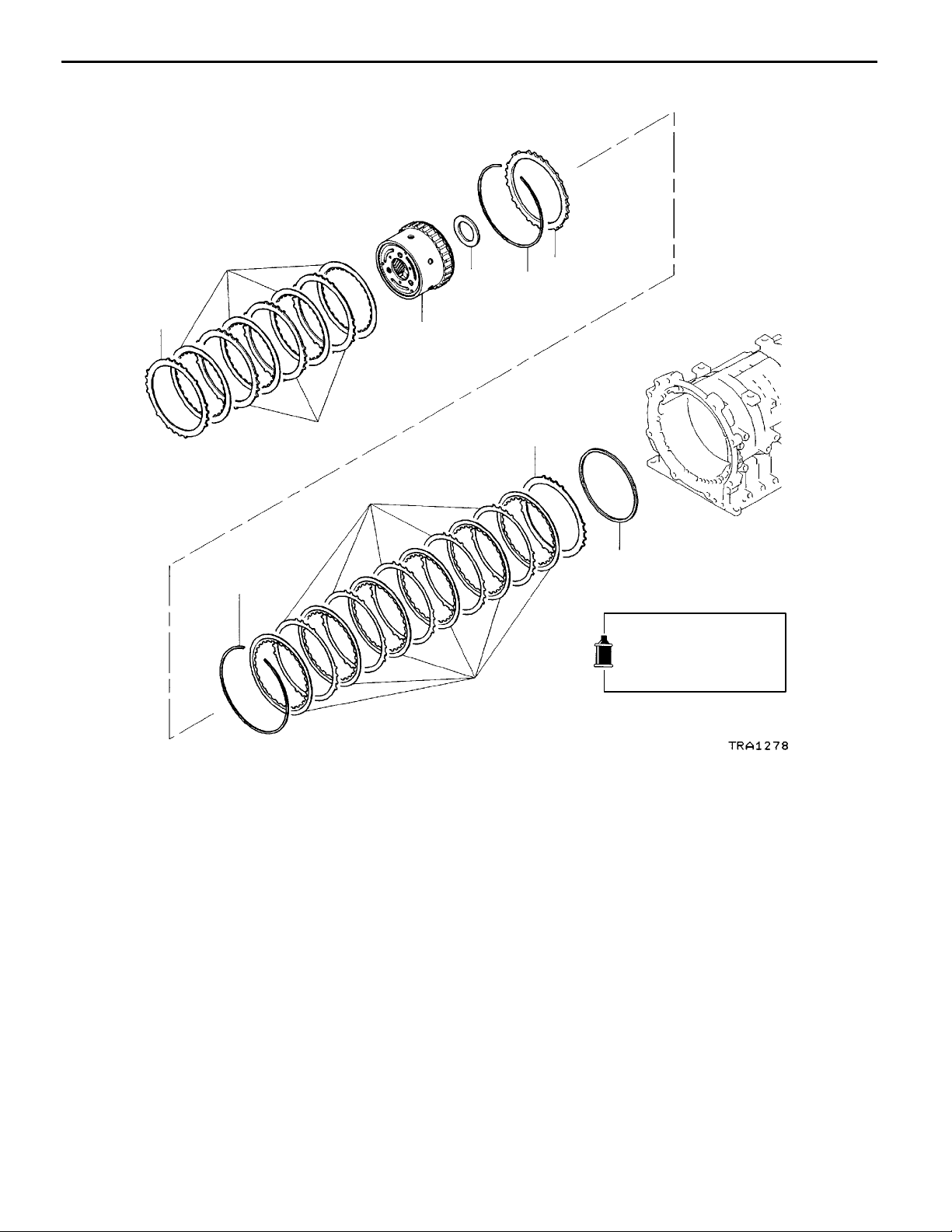
10. UNDERDRIVE CLUTCH
DISASSEMBLY AND ASSEMBLY
Apply automatic
transmission fluid to
all moving parts
before installation.
2
1
Underdrive Clutch
4
3
23E-10-1
11
12
10
9
8
7
1
5
6
5
11
3
7
10
8
13
12
9
6
2
4
E
Mar. 2000Mitsubishi Motors Corporation
13
AddedPWEE8920-I
Page 72

23E-10-2
Disassembly steps
"EA 1. Snap ring
"DA 2. Reaction plate
"DA 3. Clutch disc
"DA 4. Clutch plate
AA""CA 5. Snap ring
6. Snap retainer
"AA 7. D-ring
V5A51 -
Underdrive Clutch
"BA 8. Return spring
9. Underdrive clutch piston
"AA 10. D-ring
"AA 11. D-ring
"AA 12. D-ring
13. Underdrive clutch retainer
MD998924
Snap ring
MD998907
DISASSEMBLY SERVICE POINT
AA"
1. Set the special tools as shown in t he illustration.
2. Compress the return spring, and remove the snap ring.
SNAP RING REMOVAL
ASSEMBLY SERVICE POINTS
"AA
1. Apply ATF to the D-ring.
2. Install th e D-ring in the groove of the underdrive clutch
"BA
Align the two return spring holes with the two projections
on the underdrive clutch piston, and then assemble the return
springs.
D-RING INSTALLATION
retainer and spring retainer. Make sure that the D-ring
is not twisted or damaged when installing.
RETURN SPRING INSTALLATION
MD998924
MD998907
"CA
SNAP RING INSTALLATION
1. Set the special tools as shown in t he illustration.
2. Compress the return spring, and install the snap ring.
Snap ring
E
Mar. 2000Mitsubishi Motors Corporation
AddedPWEE8920-I
Page 73

V5A51 -
Underdrive Clutch
23E-10-3
“W”
stamp
Reaction
plate
MD998924
MB991629
A
Clutch discs
B
"DA
CLUTCH PLATE / CLUTCH DISC / REACTION
PLATE INSTALLATION
1. Alternately assemble the clutch plates and clutch discs
in the underdrive clutch retainer.
When assembling the four clutch plates, align the seciton
having no teeth (A in the illustration) with the underdrive
clutch retainer hole (B in the illustration).
Clutch platesRounded edge
2. Install the reaction plate so that it is oriented as shown
in the illustration.
Assemble in the same manner as the clutch plate so
that the section with no teeth (“A” in the illustration)
matches the retainer hole (“B” in the illustration).
"EA
SNAP RING INSTALLATION
1. Install the snap ring in the groove of the underdrive clutch
retainer.
2. Set the special tools as shown in the illustration, and
compress the clutch element.
3. Confirm that the clearance between the snap ring and
reaction plate (underdrive clutch end play) is the standard
value. If the clearance is not at the standard value, select
a suitable snap ring and adjust so that the clearance
is within the standard value.
Snap ring
End play
Standard value: 1.6 - 1.8 mm
Reaction
plate
E
Mar. 2000Mitsubishi Motors Corporation
AddedPWEE8920-I
Page 74

11. VALVE BODY
DISASSEMBLY AND ASSEMBLY
V5A51 -
Valve Body
23E-11-1
11±1Nm
Apply automatic
transmission fluid to
all moving parts
before installation.
8
6±1Nm
9
11±1Nm
1
5
7
6
4
2
3
10
11
12
14
Disassembly steps
"GA 1. Manual valve pin
"FA 2. Damping valve
"FA 3. Seal ring
"FA 4. Damping valve spring
"FA 5. Ball (orifice check ball)
"FA 6. Steel ball (orifice check ball)
"FA 7. Spring
8. Upper valve body gasket
14
13
13
11±1Nm
15
9. Separating plate
10. Lower valve body gasket
"EA 11. Steel ball (line relief)
"EA 12. Spring
"DA 13. Knock bushing
"CA 14. Knock bushing
"BA 15. Dowel pin
E
Mar. 2000Mitsubishi Motors Corporation
AddedPWEE8920-I
Page 75

23E-11-2
6±1Nm
16
21
20
19
V5A51 -
18
Valve Body
17
38
22
Apply automatic
transmission fluid to
all moving parts
before installation.
Disassembly steps
16. Solenoid support
AA""AA 17. Low/reverse brake solenoid valve
AA""AA 18. Reduction brake solenoid valve
AA""AA 19. Second brake solenoid valve
AA""AA 20. Underdrive clutch solenoid valve
AA""AA 21. Overdrive clutch solenoid valve
AA""AA 22. Torque converter clutch control sole-
noid valve
23. Stopper plate
24. Stopper plug
25. Switching valve
26. Stopper plate
27. Fail-safe valve A sleeve
37
36
24
25
23
32
30
29
35
33
28
31
34
28. Fail-safe valve A
29. Fail-safe valve A spring
30. Fail-safe valve A
31. Stopper plate
32. Fail-safe valve B sleeve
33. Fail-safe valve B
34. Stopper plate
35. Stopper plug
36. Torque converter pressure control
valve
37. Torque converter pressure control
valve spring
38. Upper valve body
2
1
27
26
E
Mar. 2000Mitsubishi Motors Corporation
AddedPWEE8920-I
Page 76

55
51
52
47
53
48
54
V5A51 -
49
44
50
40
Valve Body
41
42
45
46
23E-11-3
43
39
59
56
60
61
Apply automatic
transmission fluid to
all moving parts
before installation.
Disassembly steps
39. Manual valve
40. Roller
41. Low/reverse brake pressure control
valve sleeve
42. Low/reverse brake pressure control
valve
43. Low/reverse brake pressure control
valve spring
44. Stopper plate
45. Fail-safe valve C sleeve
46. Fail-safe valve C
47. Roller
48. Reduction brake pressure control
valve sleeve
49. Reduction brake pressure control
valve
50. Reduction brake pressure control
valve spring
51. Roller
52. Second brake pressure control valve
sleeve
53. Second brake pressure control valve
54. Second brake pressure control valve
spring
55. Roller
56. Underdrive clutch pressure control
valve sleeve
57
58
62
11±1Nm
73
72
74
67
66
71
65
70
69
68
11±1Nm
57. Underdrive clutch pressure control
valve
58. Underdrive clutch pressure control
valve spring
59. Roller
60. Overdrive clutch pressure control
valve sleeve
61. Overdrive clutch pressure control
valve
62. Overdrive clutch pressure control
valve spring
63. Stopper plate
64. Regulator valve adjusting screw
65. Regulator valve sleeve
66. Regulator valve spring
67. Regulator valve
68. Roller
69. Torque converter clutch control valve
sleeve
70. Torque converter clutch control valve
71. Torque converter clutch control valve
spring
72. Cover
73. Cover gasket
74. Lower valve body
63
64
E
Mar. 2000Mitsubishi Motors Corporation
AddedPWEE8920-I
Page 77

23E-11-4
V5A51 -
Valve Body
DISASSEMBLY SERVICE POINT
AA"
Before removing the solenoid valves, make marks with white
paint, etc., so that these valves can be reinstalled in the
original positions.
SOLENOID VALVE REMOVAL
ASSEMBLY SERVICE POINTS
"AA
1. Apply ATF, petrolatum jelly or Vaseline to O-rings, and
2. Following the marks made during removal, install each
SOLENOID VALVE INSTALLATION
install them to solenoid valves.
solenoid valve.
Dowel pin
6mm
"BA
DOWEL PIN INSTALLATION
Install the dowel pin at the specified position on the lower
valve body.
"CA
KNOCK BUSHING INSTALLATION
Install the knock bushing onto the lower valve body position
shown in the illustration.
9mm
E
Mar. 2000Mitsubishi Motors Corporation
AddedPWEE8920-I
Page 78

V5A51 -
Valve Body
23E-11-5
4.5 mm
Steel ball
"DA
KNOCK BUSHING INSTALLATION
Install the knock bushing onto the lower valve body position
shown in the illustration.
"EA
SPRING / STEEL BALL (LINE RELIEF)
INSTALLATION
Install the spring (7 mm in diameter, 17.3 mm in length) and
the steel ball (6.4 mm in diameter) onto the lower valve body
position shown in the illustration.
Seal ring
Spring
Ball
(rubber)
Steel
ball
"FA
SPRING / STEEL BALL (ORIFICE CHECK BALL)
/ BALL (ORIFICE CHECK BALL) / DAMPING
VALVE SPRING / SEAL RING / DAMPING VALVE
INSTALLATION
1. Install the spring (4.5 mm in diameter, 15.4 mm in length)
and the steel ball (6.4 mm in diameter) onto the upper
valve body position shown in the illustration.
2 Install the ball (rubber) (6.4 mm in diameter) onto the
upper valve body position shown in the illustration.
3. After installing the seal ring onto the damping valve, install
together with the damping valve spring (7.7 mm in
diameter, 35.8 mm in length) onto the upper valve body
position shown in the illustration.
Damping
valve
E
Damping
spring
Spring
Mar. 2000Mitsubishi Motors Corporation
AddedPWEE8920-I
Page 79

23E-11-6
V5A51 -
Valve Body
Manual
valve
Manual valve pin
"GA
MANUAL VALVE INSTALLATION
Fit the manual valve pin into the groove of the manual valve.
E
Mar. 2000Mitsubishi Motors Corporation
AddedPWEE8920-I
Page 80

V5A51 -
12. DIRECT ANNULUS GEAR
DISASSEMBLY AND ASSEMBLY
Apply automatic
transmission fluid to
all moving parts
before installation.
4
Direct Annulus Gear
23E-12-1
2
3
1
Disassembly steps
1. Snap ring
2. Output flange
"BA 3. Thrust bearing No.10
4. Underdrive clutch hub
7
5
"AA 5. Thrust bearing No.11
6
6. Underdrive clutch
7. Direct annulus gear
Thrust bearing No.11
E
ASSEMBLY SERVICE POINTS
"AA
Apply vaseline or petrolatum jelly on the thrust bearing No.11,
and then install on the underdrive clutch.
Caution
D
Mar. 2000Mitsubishi Motors Corporation
THRUST BEARING NO.11 INSTALLATION
Take care not to mistake the thrust bearing No.11
mounting direction.
AddedPWEE8920-I
Page 81

23E-12-2
V5A51 -
Direct Annulus Gear
Thrust bearing No.10
"BA
THRUST BEARING NO.10 INSTALLATION
Apply vaseline or petrolatum jelly on the thrust bearing No.10,
and then install on the underdrive clutch hub.
Caution
D
Take care not to mistake the thrust bearing No.10
mounting direction.
E
Mar. 2000Mitsubishi Motors Corporation
AddedPWEE8920-I
Page 82

V5A51 -
13. DIRECT CLUTCH
DISASSEMBLY AND ASSEMBLY
Apply automatic
transmission fluid to
all moving parts
before installation.
2
1
Direct Clutch
23E-13-1
4
3
Disassembly steps
"DA 1. Snap ring
"CA 2. Reaction plate
"CA 3. Clutch disc
"CA 4. Clutch plate
AA""BA 5. Snap ring
6. Spring retainer
"AA 7. D-ring
8. Return spring
9. Direct clutch piston
"AA 10. D-ring
"AA 11. D-ring
12. Direct clutch retainer
12
3
10 11
11
10
9
8
7
5
6
5
12
1
4
2
678
9
E
Mar. 2000Mitsubishi Motors Corporation
AddedPWEE8920-I
Page 83

23E-13-2
V5A51 -
Direct Clutch
MB991630 MD998924
Snap ring
MB991630 MD998924
DISASSEMBLY SERVICE POINT
AA"
1. Set the special tools as shown in t he illustration.
2. Compress the return spring, and remove the snap ring.
SNAP RING REMOVAL
ASSEMBLY SERVICE POINTS
"AA
1. Apply ATF to the D-ring.
2. Install the D-ring in the direct clutch piston and spring
"BA
1. Set the special tools as shown in t he illustration.
2. Compress the return spring, and install the snap ring.
D-RING INSTALLATION
retainer groove. Make sure that the D-ring is not twisted
or damaged when installing.
SNAP RING INSTALLATION
A
Clutch plates
Rounded edge
Snap ring
B
Reaction
plate
“R”
stamp
"CA
CLUTCH PLATE / CLUTCH DISC / REACTION
PLATE INSTALLATION
1. Alternately assemble the clutch plates and clutch discs
in the reverse clutch retainer. Align the section having
no teeth of the clutch plates (A in t he illustration) with
the reverse clutch retainer hole (B in the illustration).
2. Install the reaction plate so that it is oriented as shown
in the illustration. Assemble in the same manner as the
clutch plate so that the section with no teeth (A in the
illustration) matches the retainer hole (B in the illustration).
Clutch discs
E
Mar. 2000Mitsubishi Motors Corporation
AddedPWEE8920-I
Page 84

V5A51 -
Direct Clutch
23E-13-3
Snap ring
Snap ring
Standard value
Reaction
plate
"DA
SNAP RING INSTALLATION
1. Install the snap ring in the direct clutch retainer groove.
2. Press the entire periphery of the reaction plate with a
force of 49 N, a n d confirm that the clearance between
the snap ring and reaction plate (direct clutch e nd play)
is the standard value. If the clearance is not at the standard
value, select a suitable snap ring and adjust so that the
clearance is within the standard value.
Standard value: 1.0 - 1.2 mm
E
Mar. 2000Mitsubishi Motors Corporation
AddedPWEE8920-I
Page 85

V5A51 -
Output Shaft Support
14. OUTPUT SHAFT SUPPORT
DISASSEMBLY AND ASSEMBLY
Apply automatic
transmission fluid to
all moving parts
before installation.
2
1
23E-14-1
Disassembly steps
1. Snap ring
"AA 2. One-way clutch
4
3
3. Seal ring
4. Output shaft support
Output shaft
support
Identification
groove
One-way
clutch
E
ASSEMBLY SERVICE POINT
"AA
Install the one-way clutch in such a way that it will be oriented
in the direction shown.
Mar. 2000Mitsubishi Motors Corporation
ONE-WAY CLUTCH INSTALLATION
AddedPWEE8920-I
Page 86

15. TRANSFER
DISASSEMBLY AND ASSEMBLY
V5A51 -
Transfer
23E-15-1
1
35±6Nm
2
3
4
17
18
35±6Nm
5
6
7
19±2Nm
11±1Nm
19
10
25
35±6Nm
8
9
35±6Nm
Apply gear oil to all
moving parts before
installation.
11±1Nm
11
12
13
35±6Nm
14
15
29
28
16
30
24
11±1Nm
20
22
23
11±1Nm
35±6Nm
26
27
21
35±6Nm
31
E
Mar. 2000Mitsubishi Motors Corporation
AddedPWEE8920-I
Page 87

23E-15-2
"WA 2. 4LLC switch
"WA 5. 2WD switch
"WA 8. Center differential lock switch
"WA 11. 4H switch
"WA 14. 2WD-4WD switch
Disassembly steps
1. Vacuum hose
3. Gasket
4. Steel ball
6. Gasket
7. Steel ball
9. Gasket
10. Steel ball
12. Gasket
13. Steel ball
15. Gasket
16. Steel ball
V5A51 -
Transfer
"VA 17. Transfer case cover
"UA 18. Shift rail drive gear
"UA 19. Shift rail drive gear
20. Dust seal guard
21. Dynamic damper
22. Vehicle speed sensor
23. O-ring
24. Rear output sensor
25. O-ring
26. Front output sensor
27. O-ring
"TA 28. Shift actuator
29. O-ring
"TA 30. Main shift rail
31. Under guard (EXP)
E
Mar. 2000Mitsubishi Motors Corporation
AddedPWEE8920-I
Page 88

Apply gear oil to all
moving parts before
installation.
48
50
45
43
V5A51 -
41
42
Transfer
35±6Nm
39
36
37
40
35
38
34
23E-15-3
33
35±6Nm
32
51
49
Disassembly steps
"SA 32. Rear cover
"RA 33. Oil seal
34. Snap ring
35. Sensor rotor
36. Steel ball
37. Oil guide
"QA 38. Spacer
39. Snap ring
"PA 40. Snap ring
"OA 41. Chain cover
"NA 42. Rear output shaft
43. O-ring
44. Bearing
45. Snap ring
46. Center differential planetary carrier
47. Viscous coupling
AA""MA 48. Chain
AA""MA 49. Front output shaft
66
47
44
46
65
62
64
56
63
61
60
"MA 50. Drive sprocket
51. Bearing
"LA 52. Synchronizer inner ring
"LA 53. Synchronizer cone
"LA 54. Synchronizer outer ring
55. Synchronizer spring
"KA 56. Snap ring
57. 2-4WD clutch hub
AA" 58. Sun gear
59. Bearing
60. Wave spring
"JA 61. 2-4WD clutch sleeve
"JA 62. 2-4WD shift fork
"IA 63. Spacer
"IA 64. Steel ball
"HA 65. Snap ring
66. Differential lock hub
57
59
58
52
53
54
55
E
Mar. 2000Mitsubishi Motors Corporation
AddedPWEE8920-I
Page 89

23E-15-4
Apply gear oil to all
moving parts before
installation.
35±6Nm
67
71
68
72
73
74
76
V5A51 -
75
Transfer
83
78
77
20±2Nm
82
81
35±6Nm
Disassembly steps
"GA 67. Transfer case plate
68. Bearing
69. Counter shaft gear
"FA 70. Spacer
"EA 71. H-L clutch sleeve
"EA 72. H-L shift fork
"DA 73. Snap ring
74. H-L clutch hub
75. Low speed gear
69
70
80
79
76. Bearing
"CA 77. Rear bearing retainer
78. Transfer drive shaft
79. Dust seal guard
"BA 80. Oil seal
AB""AA 81. Oil pool cover
82. Oil guide
83. Transfer case
E
Mar. 2000Mitsubishi Motors Corporation
AddedPWEE8920-I
Page 90

V5A51 -
Transfer
23E-15-5
DISASSEMBLY SERVICE POINTS
AA"
Remove the chain, front output shaft and sun gear as a set
from the transfer case.
CHAIN / FRONT OUTPUT SHAFT / SUN GEAR
REMOVAL
MB990932
2mm
MB990938
5mm
AB"
OIL POOL COVER REMOVAL
Unstake the positions shown in the illustration to remove
the oil pool cover.
Caution
D
The oil pool cover normally does not require
disassembly. Once it is removed, the transfer case
cannot be reused.
ASSEMBLY SERVICE POINTS
"AA
Install the oil pool cover on a new transfer case. Stake the
projecting portions of the transfer so that the dimensions
will be as illustrated.
"BA
1. Use the special tools to install the oil seal on the transfer
2. Apply grease to the lip of t he oil seal.
OIL POOL COVER INSTALLATION
OIL SEAL INSTALLATION
case.
Specified grease:
MITSUBISHI genuine grease part No. 0101011 or
equivalent
"CA
REAR BEARING RETAINER INSTALLATION
The bolts used for mounting the rear bearing retainer are
pre-coated ones.
When they are to be reused, apply sealant to the threaded
portion before installation.
Specified sealant:
MITSUBISHI genuine sealant part No. MD997740 or
equivalent
E
Mar. 2000Mitsubishi Motors Corporation
AddedPWEE8920-I
Page 91

23E-15-6
V5A51 -
Transfer
Solder
"DA
SNAP RING INSTALLATION
Select a proper snap ring so that the end play of the H-L
clutch hub will have the standard value, and install the snap
ring on the transfer drive shaft.
Standard value: 0 - 0.08 mm
"EA
H-L SHIFT FORK / H-L CLUTCH SLEEVE
INSTALLATION
Apply grease to the H-L shift fork shaft inserting portion, and
install the H-L shift fork and H-L clutch sleeve in combined
state in the transfer case.
Specified grease:
MITSUBISHI genuine grease part No. 0101011 or
equivalent
"FA
SPACER INSTALLATION
1. Put pieces of solder (approx. 10 mm long and 1.6 mm
in diameter) at th e illustrated positions of the transfer
case.
2. Install the countershaft gear and transfer case plate an d
tighten the bolts to the specified torque.
3. If the pieces of solder are not crushed, pu t thicker pieces
of solder and perform Steps 1 and 2.
4. Measure the thickness of the crushed pieces of solder
with a micrometer, and select a spacer of proper thickness
so that the end play will have the standard value.
Standard value: 0 - 0.15 mm
"GA
TRANSFER CASE PLATE INSTALLATION
1. Apply grease to t he illustrated position of the high/low
shift rail inserting portion of the transfer case plate.
Specified grease:
MITSUBISHI genuine grease part No. 0101011 or
equivalent
E
Mar. 2000Mitsubishi Motors Corporation
AddedPWEE8920-I
Page 92

V5A51 -
Transfer
23E-15-7
2. Face the notched portion of the input gear in the illustrated
direction (in the direction of the countershaft gear bearing
hole).
3. Apply sealant to the illustrated position of the transfer
case.
Specified sealant:
MITSUBISHI genuine sealant part No. MD997740
or equivalent
Caution
D
Squeeze sealant out evenly to make sure that it
is not broken or excessively supplied.
4. While making sure that the notched portion of the input
gear positioned in Step 2 is in alignment with the gear
portion of the countershaft, install the transfer case plate.
Caution
D
If the sub gear does not readily come in mesh
with the countershaft gear, rotate the transfer drive
shaft, etc. to securely engage it.
"HA
SNAP RING INSTALLATION
Select a proper snap ring so that the end play of the differential
lock h u b will have the standard value, an d install it on the
transfer drive shaft.
Standard value: 0 - 0.08 mm
Steel ball
"IA
Install the steel ball in the illustrated position of the transfer
STEEL BALL / SPACER INSTALLATION
drive shaft and install the spacer with its oil groove toward
the chain cover.
E
Mar. 2000Mitsubishi Motors Corporation
AddedPWEE8920-I
Page 93

23E-15-8
V5A51 -
Transfer
"JA
2-4WD SHIFT FORK / 2-4WD CLUTCH SLEEVE
INSTALLATION
Apply grease to the 2-4WD shift fork shaft inserting portion
and install the 2-4WD shift fork and 2-4WD clutch sleeve
in combined state in the transfer case.
Specified grease:
MITSUBISHI genuine grease part No. 0101011 or
equivalent
"KA
SNAP RING INSTALLATION
Select a proper snap ring so that the end play of the 2-4WD
clutch hub will have the standard value, and install it on the
sun gear.
Standard value: 0 - 0.08 mm
"LA
SYNCHRONIZER OUTER RING / SYNCHRONIZER
CONE / SYNCHRONIZER INNER RING
INSTALLATION
1. Combine the synchronizer outer ring, synchronizer cone
and synchronizer inner ring, press them against the drive
sprocket, and measure the dimension shown in the
illustration.
Limit: 0.3 mm
2. If the dimension is out of the limit value, replace them
with a synchronizer ring set.
3. Apply gear oil to the synchronizer outer ring and
synchronizer inner ring.
4. Line up the notched portion of the 2-4WD clutch hub
with t he projecting portion of the synchronizer ring and
install the ring on the 2-4WD clutch hub.
"MA
DRIVE SPROCKET / FRONT OUTPUT SHAFT /
CHAIN INSTALLATION
1. Set the chain in mesh with the drive sprocket a nd front
output shaft sprocket and install them in the transfer case.
E
Mar. 2000Mitsubishi Motors Corporation
AddedPWEE8920-I
Page 94

V5A51 -
Transfer
23E-15-9
2. Install the drive sprocket so that its illustrated holes will
match the projecting portions of the synchronizer cone.
"NA
REAR OUTPUT SHAFT INSTALLATION
Apply grease to the O-ring at the illustrated position and install
the rear output shaft.
Specified grease:
MITSUBISHI genuine grease part No. 0101011 or
equivalent
"OA
CHAIN COVER INSTALLATION
1. Apply grease to the indicated 2-4WD shift rail inserting
portion.
Specified grease:
MITSUBISHI genuine grease part No. 0101011 or
equivalent
2. Apply a bead of sealant to the illustrated position of the
chain cover.
Specified sealant:
MITSUBISHI genuine sealant part No. MD997740
or equivalent
Caution
D
Squeeze the sealant out evenly to make sure that
it is not broken or excessively supplied.
"PA
SNAP RING ISNTALLATION
1. Install the snap ring in the bearing groove of the rear
output shaft.
2. With the rear output shaft pressed against the chain cover,
measure the clearance between the chain cover and snap
ring.
3. Select a snap ring whose thickness is the dimension of
the measured clearance plus the standard value.
Standard value: 0.12 - 0.24 mm
E
Mar. 2000Mitsubishi Motors Corporation
AddedPWEE8920-I
Page 95

23E-15-10
V5A51 -
Transfer
4. Remove the snap ring from the bearing groove of the
rear output shaft, install the selected snap ring, and
reinstall the removed snap ring in the bearing groove
of the rear output shaft.
Concave
portion
Projection
MB990938
MB990932
"QA
SPACER INSTALLATION
1. With the rear output shaft pressed toward the chain cover,
measure the projection of the bearing from the chain
cover.
Caution
D
Measure the projection with the snap ring
installed.
2. Measure the dimension of the rear cover concave portion
at the illustrated position.
3. Subtract the measured value in Step 1 from the measured
value in Step 2 to calculate the clearance between the
bearing and rear cover. Select a proper spacer so that
the clearance will have the standard value.
Standard value: 0 - 0.12 mm
"RA
OIL SEAL INSTALLATION
1. Use the special tools to install the oil seal in the rear
cover.
2. Apply grease to the lip of t he oil seal.
Specified grease:
MITSUBISHI genuine grease part No. 0101011 or
equivalent
"SA
REAR COVER INSTALLATION
Apply sealant to the illustrated position of the chain cover.
Specified sealant:
MITSUBISHI genuine sealant part No. MD997740 or
equivalent
Caution
D
Squeeze the sealant out evenly to make sure that
it is not broken or excessively supplied.
E
Mar. 2000Mitsubishi Motors Corporation
AddedPWEE8920-I
Page 96

V5A51 -
Transfer
23E-15-11
Mark
Third gear
"TA
MAIN SHIFT RAIL / SHIFT ACTUATOR
INSTALLATION
1. Apply grease to the O-ring.
Specified grease:
MITSUBISHI genuine grease part No. 0101011 or
equivalent
2. Combine the main shift rail key with actuator key and
insert them in the transfer case.
"UA
SHIFT RAIL DRIVE GEAR INSTALLATION
Install the shift rail drive gear with its marked tooth in mesh
with the third gear groove of each shift rail.
"VA
TRANSFER CASE COVER INSTALLATION
Apply sealant to the illustrated position of the transfer case
cover.
Specified sealant:
MITSUBISHI genuine sealant part No. MD997740 or
equivalent
Caution
D
Squeeze the sealant out evenly to make sure that
it is not broken or excessively supplied.
A
D
E
B
C
"WA
Install th e switches in the right positions.
SWITCH INSTALLATION
Switch name
A 4LLC switch Black Brown
B 2WD switch Black Black
C Center differential
lock switch
D 4H switch Blue White
E 2-4WD switch Blue Black
Tube color Connector color
Blue Brown
INSPECTION
SWITCHES
Check for the continuity between the connector terminal and
switch body. Replace the switch if found faulty.
Switch state Continuity
Switch end pressed No
Switch end released Yes
E
Mar. 2000Mitsubishi Motors Corporation
AddedPWEE8920-I
Page 97

V5A51 -
16. TRANSFER CASE PLATE
DISASSEMBLY AND ASSEMBLY
Apply gear oil to all
moving parts before
installation.
Transfer Case Plate
6
23E-16-1
20±2Nm
1
2
3
Disassembly steps
"BA 1. Bolt
2. Bearing retainer
3. Transfer input gear
"AA 4. Oil seal
5. Baffle plate
6. Transfer case plate
MB990938
MB990936
5
4
ASSEMBLY SERVICE POINTS
"AA
1. Use the special tool to install the oil seal.
2. Apply grease to the lip of t he oil seal.
OIL SEAL INSTALLATION
Specified grease:
MITSUBISHI genuine grease part No. 0101011 or
equivalent
E
Mar. 2000Mitsubishi Motors Corporation
AddedPWEE8920-I
Page 98

23E-16-2
V5A51 -
Transfer Case Plate
"BA
BOLT INSTALLATION
Apply sealant to the threads.
Specified sealant:
MITSUBISHI genuine sealant part No. MD997740 or
equivalent
NOTE
New bolts are precoated with sealant, so sealant does not
need to be applied.
E
Mar. 2000Mitsubishi Motors Corporation
AddedPWEE8920-I
Page 99

17. INPUT GEAR
DISASSEMBLY AND ASSEMBLY
V5A51 -
Input Gear
23E-17-1
Apply gear oil to all
moving parts before
installation.
2
1
Disassembly steps
"BA 1. Snap ring
AA""AA 2. Ball bearing
3. Snap ring (some model)
4. Cone spring (some model)
5. Sub gear (some model)
6. Transfer input gear
5
4
3
6
DISASSEMBLY SERVICE POINT
MD998801
AA"
Use the special tool to remove the ball bearing.
BALL BEARING REMOVAL
ASSEMBLY SERVICE POINTS
MD998812
"AA
Use the special tools to install the ball bearing.
MD998826
E
Mar. 2000Mitsubishi Motors Corporation
BALL BEARING INSTALLATION
AddedPWEE8920-I
Page 100

23E-17-2
V5A51 -
Input Gear
"BA
SNAP RING INSTALLATION
1. Install the thickest snap ring that can be fitted in the
snap ring groove of the input gear.
2. Make sure that the ball bearing end play meets the
standard value.
Standard value: 0 - 0.06 mm
E
Mar. 2000Mitsubishi Motors Corporation
AddedPWEE8920-I
 Loading...