

Mitsubishi V45CB WD-82CB1, V45CA WD-73CA1, V45C WD-73C11, WD-92840, WD-73740 User Manual
...Page 1
ECHNICAL
RAINING
T
2011
Technical Training Manual
Including…
Down-to-1
High Speed Troubleshooting
V46
L75-A94
2012
V45
Chassis
DLP
®
V46
Chassis
HOME CINEMA TV
V45C V45 V45CA
WD-73C11 WD-73640 WD-73CA1
V45+
V45++ V45CB
WD-73740 WD-73840 WD-82CB1
WD-82740
WD-82840
WD-92840
Copyright © 2011 Mitsubishi Electric Visual Solutions America, Inc.
All Rights Reserved
Page 2

Page 3

MITSUBISHI ELECTRIC
2011-2012
Technical Training Manual
Table of Contents
Introduction ........................................................................................................................... 5
Product line ......................................................................................................................... 5
Features and Technologies .................................................................................................. 6
New Technologies .............................................................................................................. 8
Chapter 1 - LASERVUE ...................................................................................................... 15
Safety ................................................................................................................................ 15
Disassembly and Parts Replacement ................................................................................ 17
Service Procedures ............................................................................................................ 23
Down-to-1 Troubleshooting ............................................................................................. 31
Chapter 2 - DLP
Disassembly and Parts Replacement ................................................................................ 35
Service Procedures ............................................................................................................ 23
Down-to-1 Troubleshooting ............................................................................................. 57
Circuit Block Diagrams .................................................................................................... 61
®
HOME CINEMA ..................................................................................... 35
3
Page 4

4
Page 5
Introduction
Introduction
DLP
®
HOME CINEMA
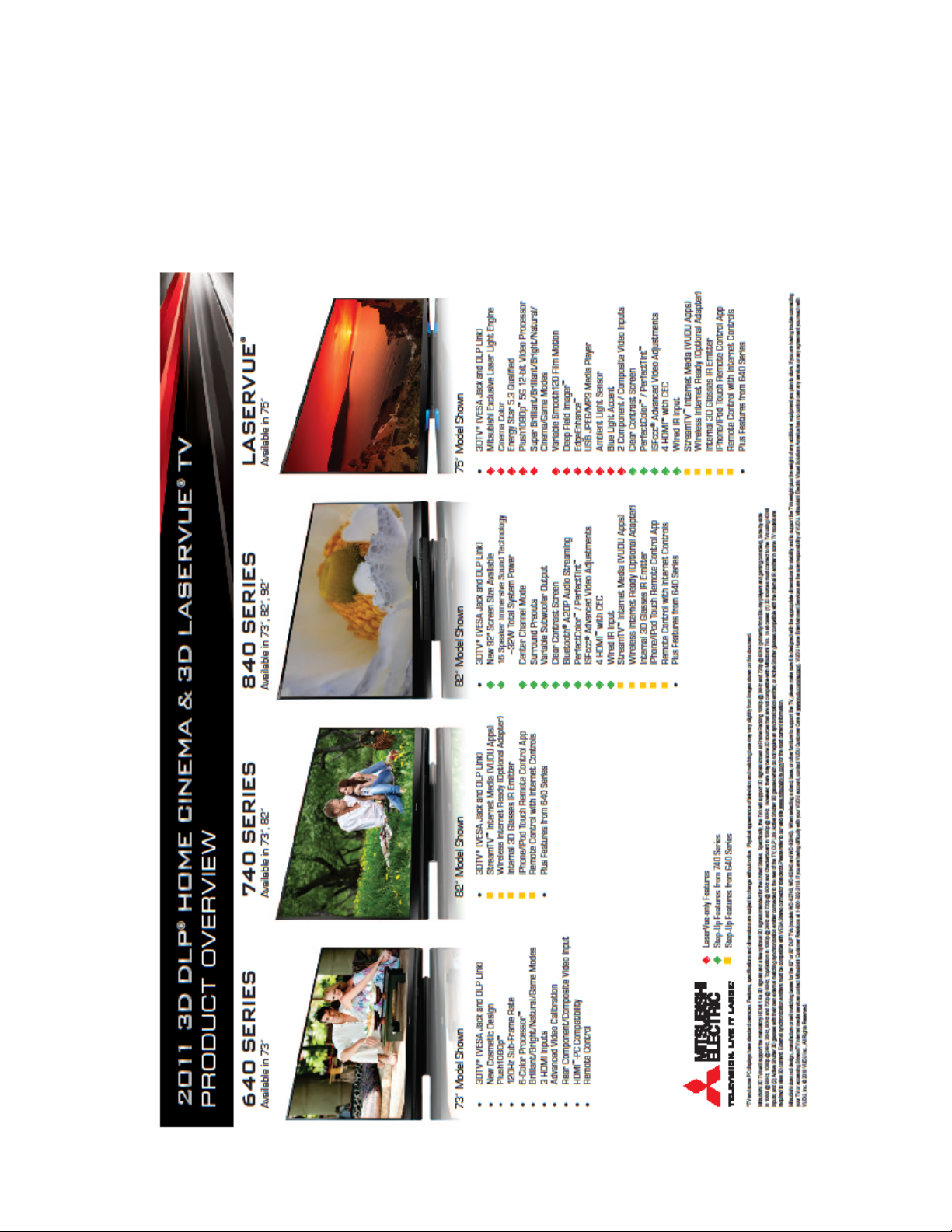
This training manual will cover Mitsubishi’s 2011-2012 TV Product Line shown below broken down by
category, chassis, display technology and light source.
Product Category Chassis Display Technology Light Source
LASERVUE V46 Rear Projection DLP RGB Lasers
DLP Home Cinema V45 Rear Projection DLP High Pressure Discharge Lamp
The full TV Product Line is shown below by size, sub-chassis and model.
LASERVUE
SIZE V46
75” L75-A94
DLP Home Cinema
SIZE V45C V45 V45CA V45+
73” WD-73C11 WD-73640 WD-73CA1 WD-73740
82” WD-82740
92”
5
V45++
WD-73840
WD-82840
WD-92840
V45CB
WD-82CB1
Page 6
Introduction
This Introduction will discuss some of the newest features and technologies. The remainder of the manual is
divided into 2 sections to cover the
LASERVUE and DLP Home Cinema product categories separately. While
this manual can be used as a service aid, always refer to the Service Manual for complete service information
and safety instructions.
FEATURES and TECHNOLOGIES
A matrix of many of the features included in the 2011-2012 product line follows. Also, several of the newest
6
Page 7

Introduction
TECHNOLOGIES
Mitsubishi’s 2011-2012 TV product line includes several technologies either new to the market place or
introduced in the recent past. These technologies include:
3D with built in IR synchronization emitters.
Stream TV™ Internet Media
Wireless Internet Ready and Built-in Wireless Internet
Bluetooth
iPhone
®
A2DP Audio Streaming
®
Remote Control App
In addition, Mitsubishi’s Reliability and Service Technologies have evolved yet again. These technologies
will be discussed further.
3D
2011-2012 Mitsubishi TVs will support the mandatory HDMI 1.4a 3D signals intended for the United
States. However, there may be some 3D sources that are not compatible with the TVs. Specifically, the
TVs will support the 3D signals known as:
Frame Packing 1080p/24Hz and 720p/60Hz (primarily from Blu-ray players and gaming consoles).
Side-by-Side in 1080i/60Hz, 1080p/24Hz/30Hz/60Hz and 720p/60Hz.
Top/Bottom in 1080p/24Hz and 720p/60Hz.
Checkerboard 1080p/60Hz.
In all cases:
(1) 3D sources must connect to the TV using the HDMI inputs or via StreamTV™ Internet Media.
(2) Active Shutter 3D glasses are required in order to view 3D content. They must be synchronized
using either IR or DLP-Link. IR synchronization must use either the TV’s internal IR emitter or an
external IR emitter connected to the rear of the TV.
7
Page 8

Introduction
Stream TV™ Internet Media
Introduced last year, internet media capabilities have been expanded to many more models this year by including an Ethernet port and wireless ready or wireless internet connections. This permits instant access to
an extensive library of high quality entertainment and social media content. StreamTV provides consumers
with over 100 different applications.
Internet services provided by VUDU™ Apps let you access many popular on-line applications. In addition
to free content, VUDU’s movie service lets you buy and rent movies through the TV. Visit VUDU.com to
learn more about available movie titles, prices, and services offered. For a list of recommended routers
and switches, see the Support > FAQ section at VUDU.com.
Requirements for StreamTV internet media:
Broadband internet service (at least 2 Mbps for SD, • 4 Mbps for HD, and 8 Mbps for 1080p HDX)
Internet connection (wired or wireless).
Computer access to the VUDU.com website (required for initial account activation).
A credit card for rental and purchase transactions from VUDU’s movie service.
Wired Internet, Wireless Internet Ready and Built-in Wireless Internet
These technologies are exactly what they say they are. Requirements are as follows:
Wired: Category-5 (CAT-5) Ethernet cable connected from the LAN Port of the TV from either a
router or modem providing high speed internet service.
Wireless Ready: Azurewave AW-NU231 USB wireless adapter plugged into the TV’s USB port.
Note: At this time, these are the only wireless adaptors available on the market that can be used.
More options may be available in the future.
Wireless and Built-in Wireless: IEEE 802.11n compliant wireless network router providing highspeed internet service.
Bluetooth® A2DP Audio Streaming
The Bluetooth specification for basic audio provides a frequency response designed for voice communication. Bluetooth’s Advanced Audio Distribution Profile, or A2DP, allows high-fidelity stereo audio to be
streamed from the customer’s Bluetooth device to the TV. A A2DP enabled Bluetooth device (phone, media player, etc.) is required.
®
iPhone
Remote Control App
Owners of Apple’s iPhone or iPod Touch devices can obtain an optional App (application) that will give
the device remote control capabilities. They can then control their TV over the wireless internet connection.
From a Service Technician’s Point of View…
New technologies always present a challenge to the service technician. The customer expects the technology to work to whatever expectation he has in mind. And if it doesn’t, he expects the service technician to
wave his “magic wand” and make it all better. In most cases, problems are not due to a failure. The customer simply does not understand the feature’s use, capabilities, requirements or set-up. Since the Service
Technician’s primary job is to repair failures, the customer problems have to be eliminated first. When
receiving a customer complaint about a new technology, the best first course of action is to point the customer to Mitsubishi’s Operational Assistance department at 800-332-2119.
8
Page 9

Introduction
9
Page 10

Introduction
Reliability and Serviceability Technologies—Simplified!
If one word could be used to describe the reliability and serviceability technologies in Mitsubishi’s 20112012 TV products, it would be simplified.
LASERVUE
The second generation V42 chassis is a complete redesign of the V40. It is, well... simplified. How?
The Screen is stationary. No motors. No moving parts. No shipping screws.
The Fiber Optic Cables have been eliminated. No optical connectors.
The Mirror is flat.
DLP Home Cinema
The Chassis is held in the cabinet by only 4 screws. And, disassembly is simplified by a reduction
in the number of screws necessary to remove the PWB-MAIN. Comparing the base models V43
to V41 shows a screw reduction of more than 42%. The high end models screw reduction is more
than 32%. And the V41 seemed simple!
The Optical Engine assembly has been redesigned to a more compact design and is held in the
cabinet by only 3 screws.
The PWB-BALLAST is held in place by a single clip.
The screw on DVI Cable has been replaced by a finger locking LVDS Ribbon Cable.
DLP Home Cinema
The Self Diagnostics feature is self activated when the set is in the shut down condition. No pro-
cedure necessary to obtain an Error Code.
The Error Code read-out is now color coded. It’s now simplified to the point where a customer
can read the Error Code.
Software updates can be performed on-line automatically (Internet Media models).
Bluetooth circuit is on a separate PWB to simplify troubleshooting.
Features, specifications and dimensions are subject to change without notice.
Digital Light Processing, Digital Micro mirror Device, and DLP are trademarks or registered trademarks of Texas Instruments.
ENERGY STAR and the ENERGY STAR mark are registered marks owned by the U.S. government. Dolby, Dolby Digital and
Dolby Pro Logic are registered trademarks of Dolby Laboratories. HDMI, the HDMI logo and High-Definition Multimedia
Interface are trademarks or registered trademarks of HDMI Licensing, LLC. “x.v.Color” is a trademark of Sony Corporation.
Bluetooth and the Bluetooth trademarks are owned by Bluetooth SIG, Inc. iPhone is a registered trademark of Apple Inc.
is a registered trademark of Textron.
6-Color Processor™, DeepField Imager™, Easy Connect™, Net Command®, PerfectColor™, PerfecTint™, Plush 1080p®,
EdgeEnhance™, Smooth120Hz™, True120Hz™. True240Hz™, StreamTV™,
Solutions America, Inc.
LASERVUE™ are Mitsubishi Electric Visual
TORX
10
Page 11

Chapter 1
SIZE V46
75” L75-A94
SAFETY
Like the first generation V40 LASERVUE chassis, the V46 chassis includes laser technologies that have
safety requirements that are separate and different than those in other TVs. Prior to servicing this type
product, it is important to read and understand all safety requirements. The V40 Technical Training Manual includes a section on the Fundamentals of Laser and Laser Safety. It is available for download from
new.3diamonds.com. In addition, the laser safety requirements specific to the V46 chassis are repeated
from the Service Manual here. Refer to the Service Manual for all other safety instructions.
11
Page 12
SAFETY PRECAUTIONS
NOTICE: Observe all cautions and safety related notes located inside the receiver cabinet and on the receiver
chassis.
WARNING:
1. Operation of this receiver with the covers removed presents both a shock hazard and a hazard from laser ra diation. Work on the receiver should not be attempted by anyone who is not thoroughly familiar with the precautions necessary when working on high voltage and laser based equipment.
2. When service is required, observe the original lead dress. Where a short-circuit has occurred, replace those
components that indicate evidence of overheating.
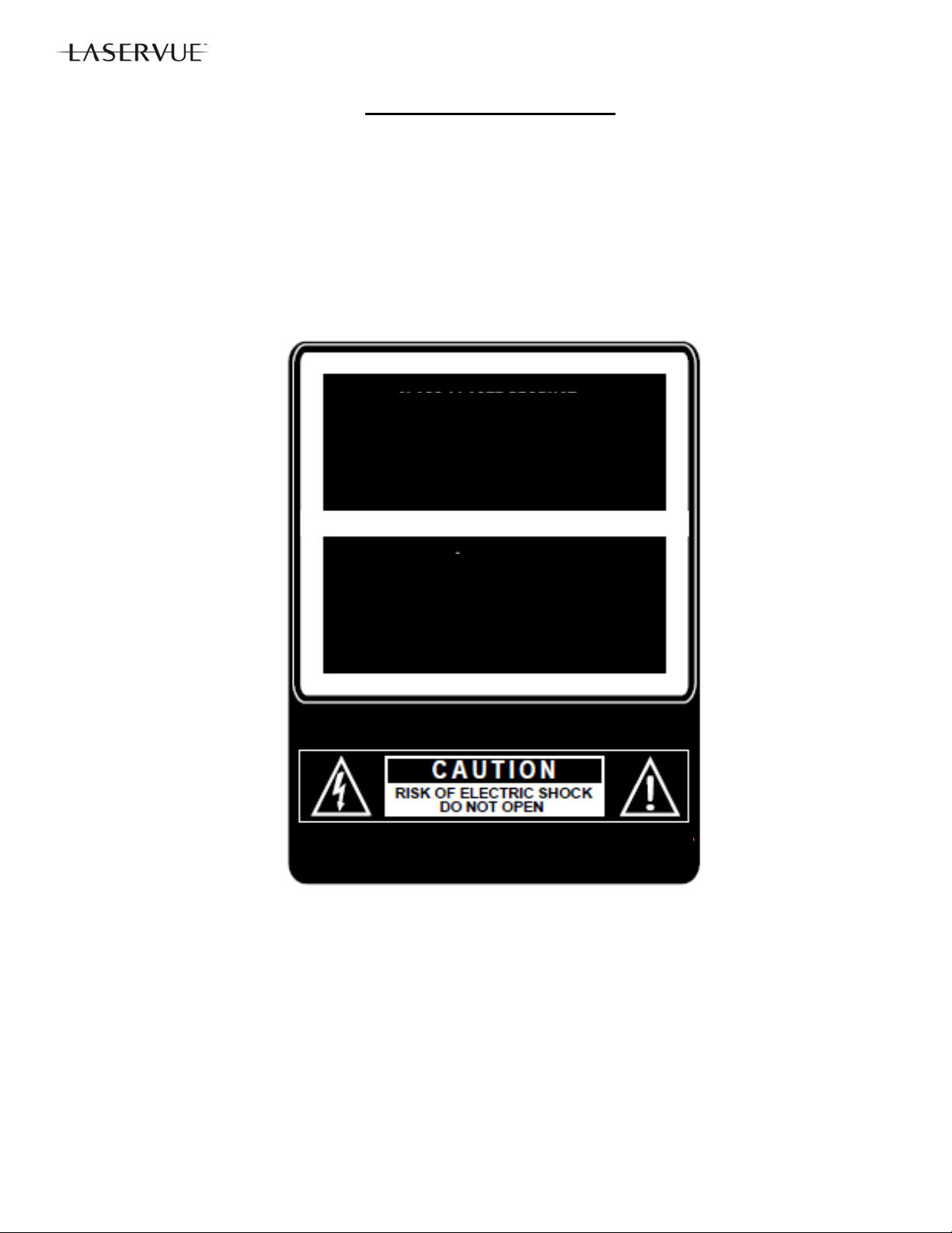
CAUTION:
This TV is a CLASS 1 laser product. This TV poses no risk to eyes or skin during normal use. An exposure hazard
may exist only if the protective housing is removed.
This TV contains a CLASS 4 laser device, which by itself may be hazardous. However, this TV incorporates a protective housing, optics and electronics such that there should be no exposure to unsafe levels of laser light during normal
operation and proper service.
This TV is in compliance with the requirements of IEC 60825-1 Ed. 2(2007).
CLASS 1 LASER PRODUCT
Complies with FDA performance standards
for laser products except for deviations
pursuant to Laser Notice No. 50, dated June
24th, 2007.
APPAREIL À LASER DE CLASS 1
Se conforme aux norms de rendement du
FDA relatives aux produits laser sauf en ce
qui concerne les déviations conformément à
La Notice Laser No 50 du 24 Juin 2007
AVIS: Risque de choc electrique. Ne pas ouvrir.
12
Page 13
Caution: Use of controls or adjustments or performance of procedures other than those specified herein may result in
hazardous radiation exposure. Use external or remote controls to operate the product. Connection to signal sources
and power are accomplished through the external connectors.
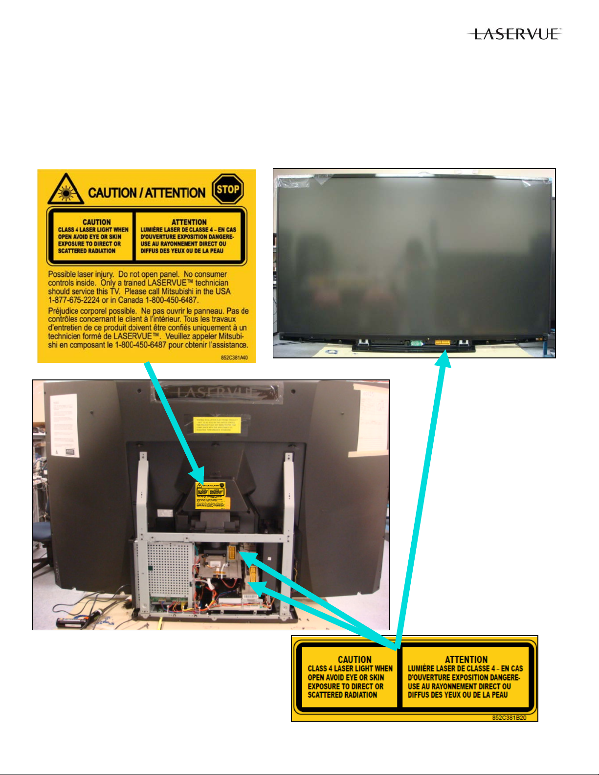
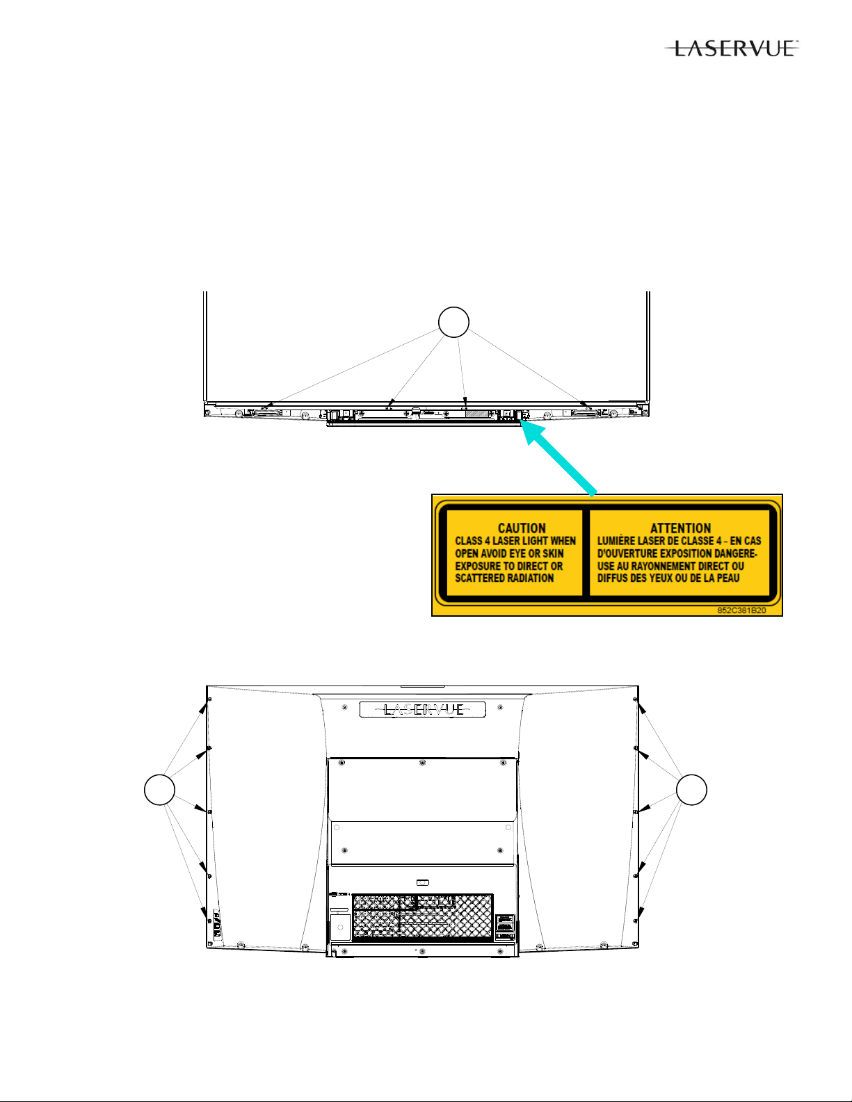
1. The following precautions must be taken to avoid exposure to hazardous laser radiation during service.
Prior to removing items marked with either of the two labels shown below, AC power mu st be removed. AC power
must not be re-applied until the cover(s) are replaced back into their original position and all screws are in place.
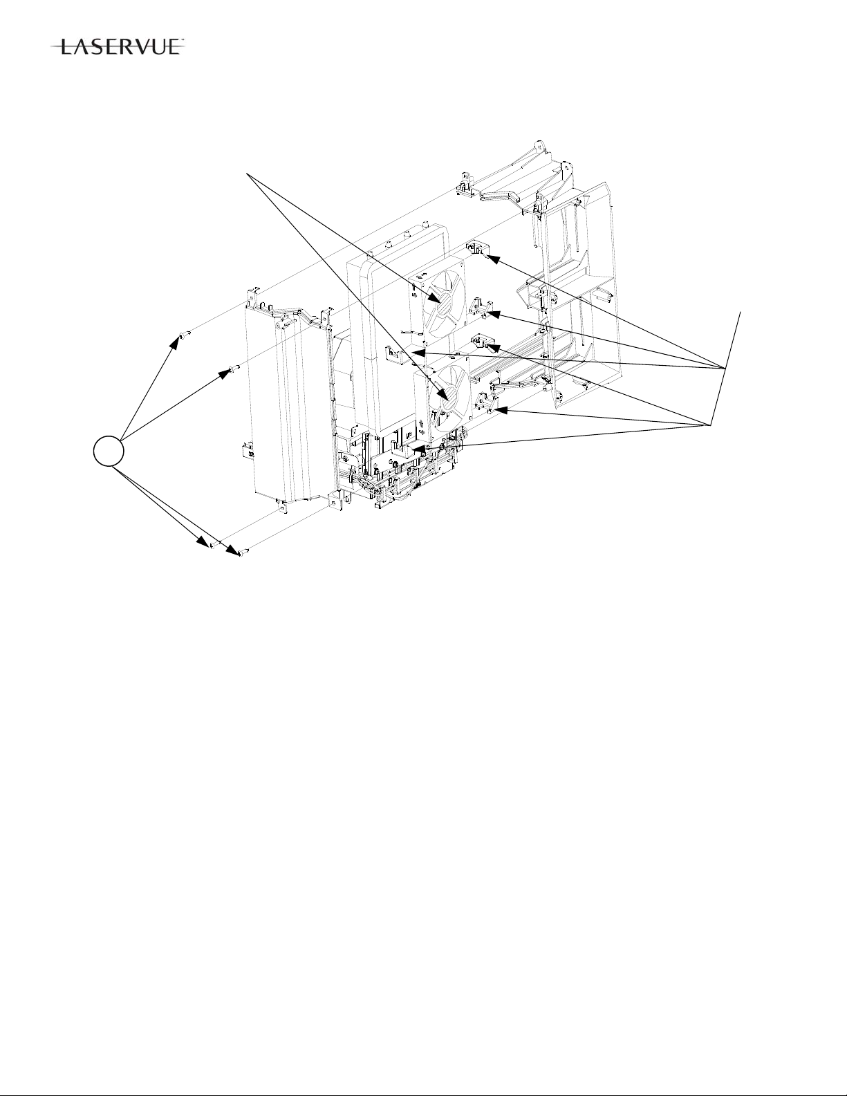
The specific Class 4 areas in the V46 chassis include the Scre en Assembly, the Light Source Unit and the Optical
Engine, indicated below.
13
Page 14

DISASSEMBLY & PARTS REPLACEMENT
CAUTION: Prior to disassembly, remove AC power. Do not re-apply AC power until the set
has been fully re-assembled and inspected for safety as described on page 12.
IMPORTANT NOTES:
1. Disassembly beyond what is shown in this manual is not recommended.
2. The following assemblies are replacement items that should not be disassembled:
Electrical Chassis—Replacement is supplied complete with PWBs. However PWBs can be replaced
individually.
Light Source Unit—Replacement is supplied complete with fans and ducts. However Exhaust Fans can
be replaced individually.
Optical Engine—Replacement is supplied complete with the DMD fan. However the DMD Fan can be
replaced individually.
3. Do not allow the rear of the screen to come into contact with any other surface including cleaning cloths or
fingers. Remove dust or other debris by blowing with a dry air source.
Back Cover Removal
1. Remove screws (A) from the back cover (Star Head/TORX® T20).
2. Remove the back cover from the TV.
A
A
A
A
A
A
14
Page 15
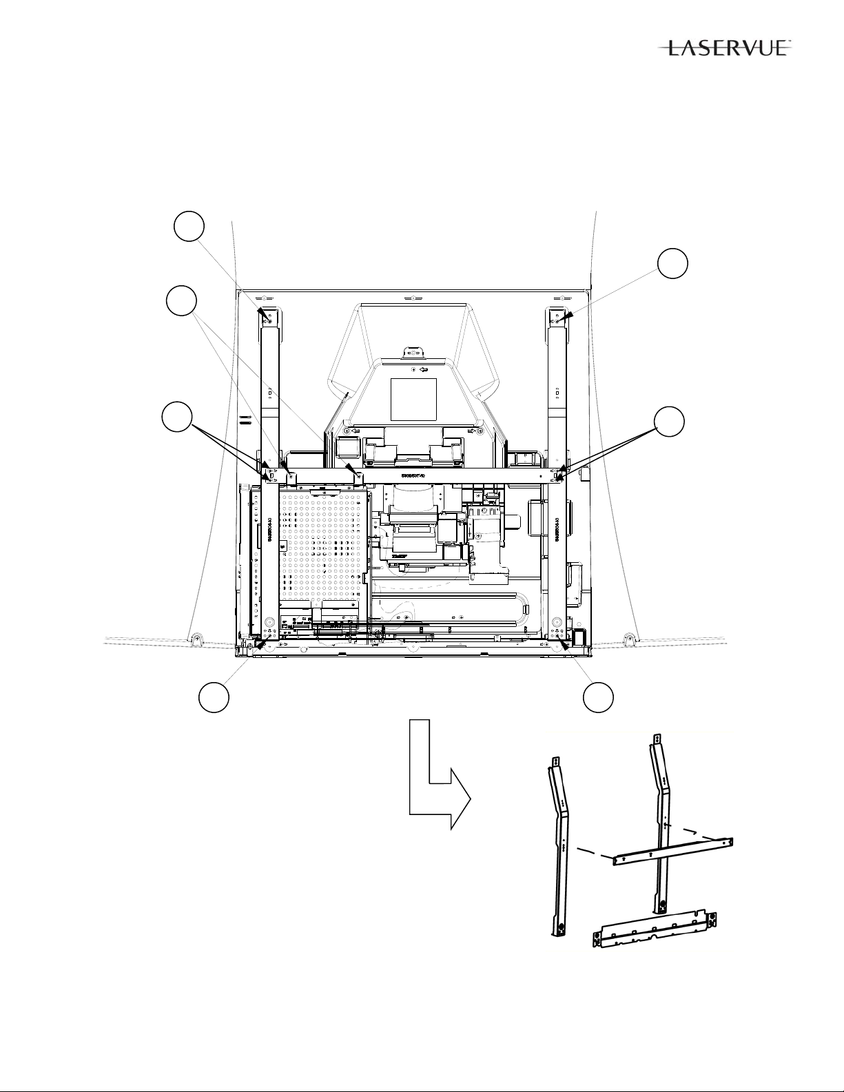
Rear Cabinet Frame Removal
1. Remove screws (A) from the Rear Cabinet Frame.
2. Remove the Rear Cabinet Support Frame from the TV.
A
A
A
A
A
A
A
15
Page 16
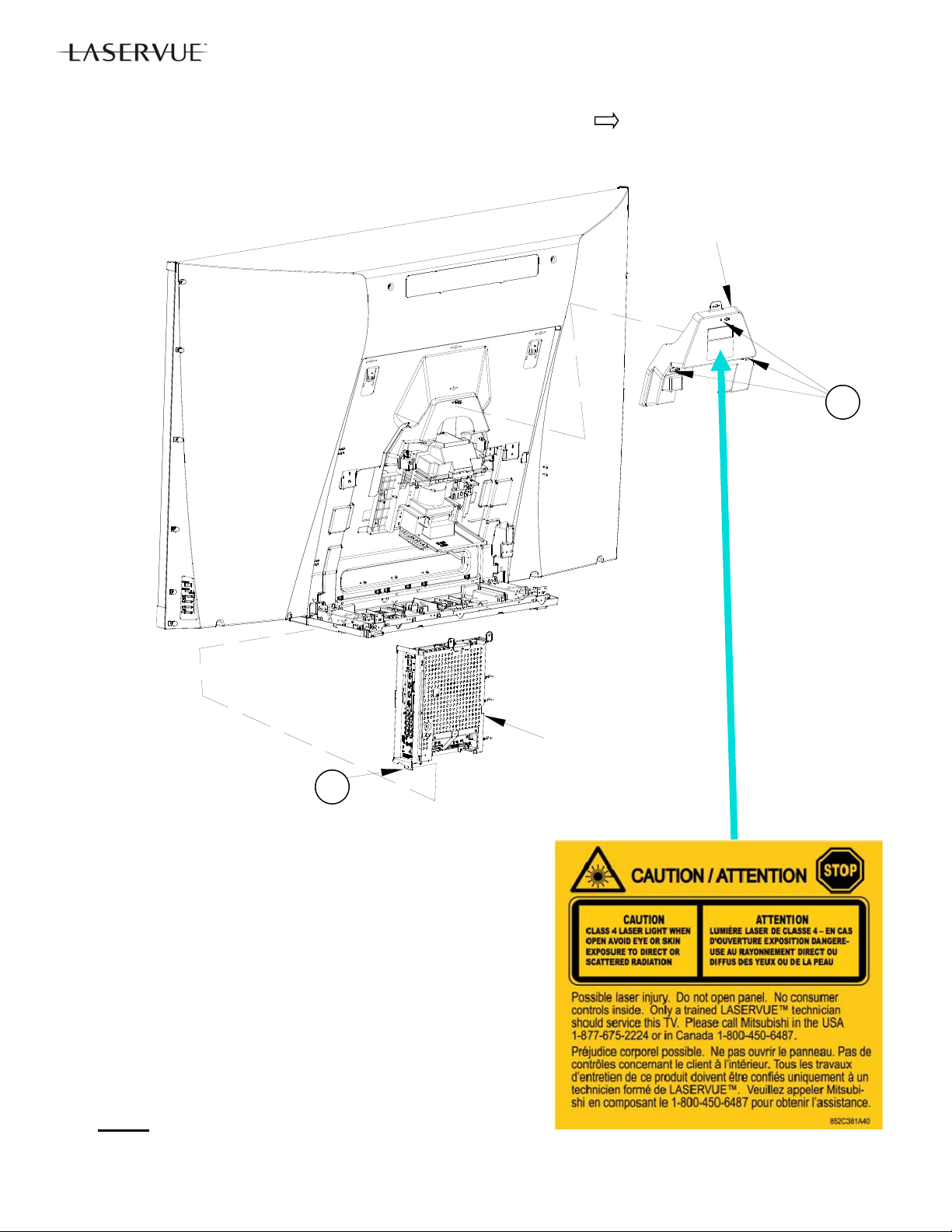
Service Cover Removal (For Light Source Unit and Optical Engine Replacement)
1. Remove screws (A) indicated on the Service Cover by the arrows
2. Remove the Service Cover in the direction indicated.
SERVICE
COVER
A
B
Electrical Chassis Removal
1. Disconnect all cables connecting to the chassis.
2. Remove screw (B).
3. Slide the chassis up and out of the cabinet.
Note: After replacing either the Electrical Chassis or PWB-MAIN,
see Data Transfer section and perform the following procedure s:
1. Restore Engine Data From Backup
2. Restore Geometry Data From Backup.
3. Restore ISF Settings From Backup (Only if backup USB
memory device is available).
IMPORTANT REPLACEMENT NOTE: If the customer has subscribed to VUDU (Internet program provider), the customer must be
instructed to contact VUDU to re-activate their account after a replacement CHASSIS or PWB-MAIN has been installed. The original
part cannot
bishi per policy.
be installed in another TV. It must be returned to Mitsu-
16
ELECTRICAL
CHASSIS
Page 17
A
A
A
B
A
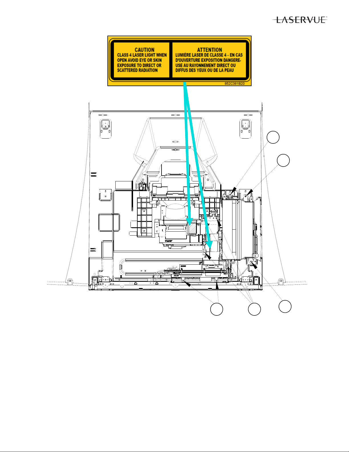
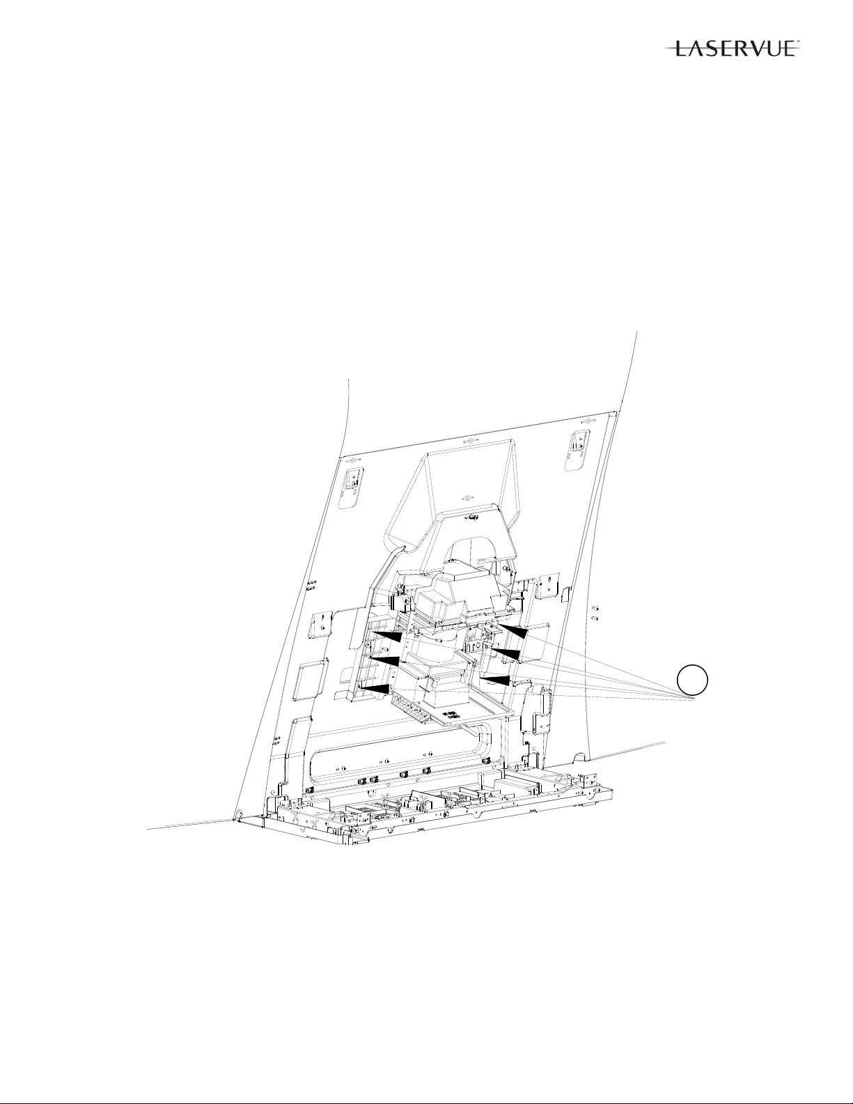
Light Source Unit Removal
NOTE: The Light Source Unit is supplied complete with fans and ducts. However the Exhaust Fans can be replaced
individually.
1. Disconnect all cables connecting to the Light Source Unit.
2. Remove Screws (A) and (B).
3. Remove the Light Source Unit from the cabinet.
Light Source Unit Replacement
1. After a new Light Source Unit is installed, perform the “Select Calibration Table” procedure as described in
the Service Adjustments section.
17
Page 18
A
Fan Labels
Facing Out
Corner
Cushions
3 Per Fan
Light Source Exhaust Fan Removal
NOTE: Disassemble Duct Assembly for Fan replacement only. Otherwise order the complete Light
Source Unit.
1. Remove Screws (A).
2. Separate the Front and Rear Air Ducts.
IMPORTANT: Do not disassemble the Light Source Unit any further.
18
Page 19
Optical Engine Removal
1. Remove Screws (A).
2. Remove the Optical Engine from the cabinet.
IMPORTANT: Do not disassemble the Optical Engine further than DMD Fan replacement.
Optical Engine Replacement
After a new Optical Engine is installed, perform the following procedures:
1. TSP Alignment as described in the Service Adjustments section.
2. “Save Engine and Geometry Setting to Backup” procedure as described in the Data Transfer section of the
Service Adjustments.
19
A
Page 20
COVER-FRONT Removal
1. Remove Back Cover and remove Screw (A).
2. Remove Screws (B).
3. Pull COVER-FRONT away from the front of the cabinet.
B B
A
COVER-FRONT
(Example)
20
Page 21
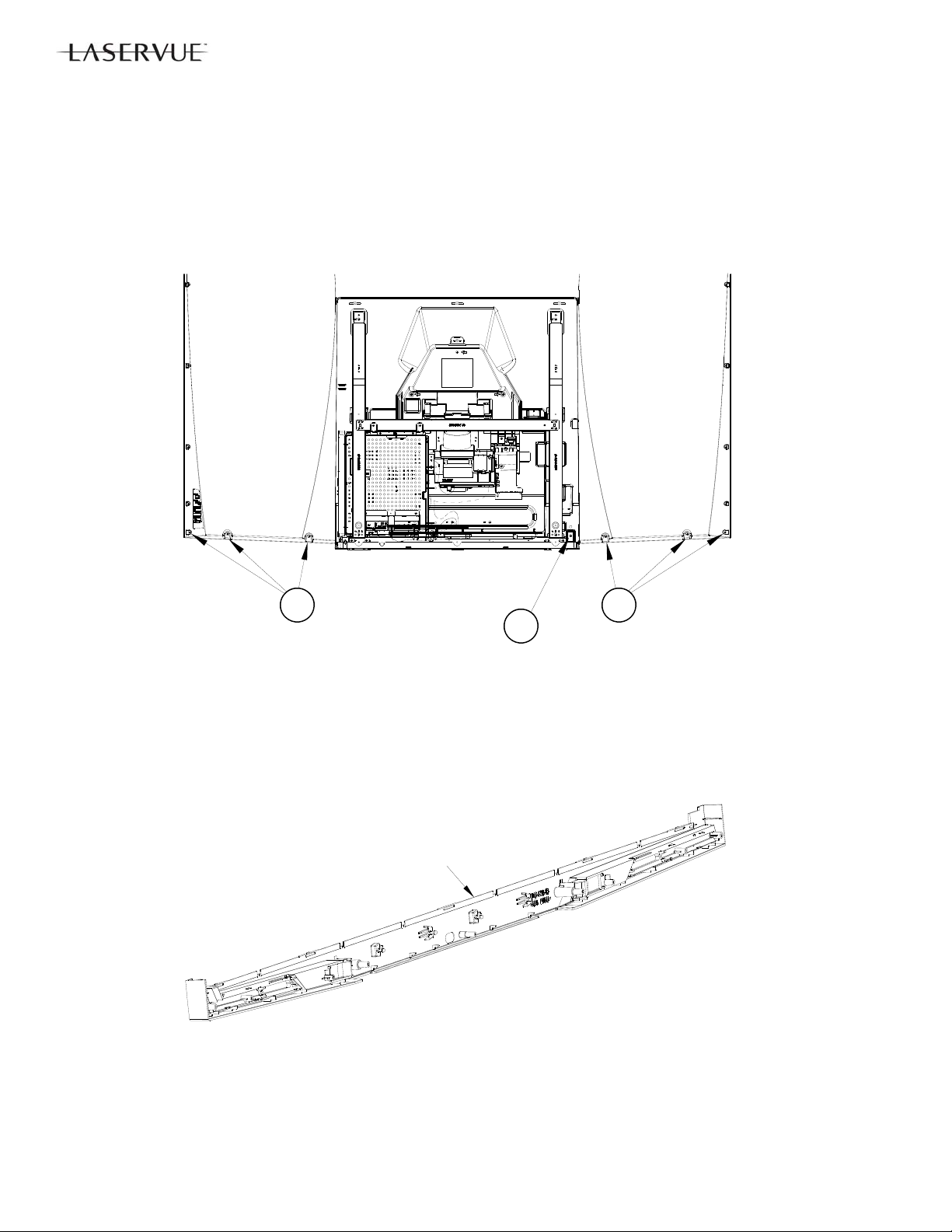
Screen Assembly Removal -
Note: The Screen Assembly and screens are not considered to be field replaceable items.
1. Remove the COVER-FRONT.
2. Remove Screws (A) from the bottom front.
3. Remove Screws (B) from the rear sides.
4. Remove the Screen Assembly from the cabinet.
IMPORTANT: Do not allow the rear of the screen to come into contact with any other surface including cleaning cloths or fingers. Remove dust or other debris by blowing with a dry air source.
IMPORTANT: Do not disassemble the Screen Assembly.
A
B B
21
Page 22
SERVICE PROCEDURES
REMOTE CONTROL USE FOR SERVICE
Many service functions and adjustments are accessed using the Remote Control. See below.
22
Page 23

OPTION MENU
OPTION MENU
1. Press the <MENU> button on the remote control.
2. Press the buttons <2-4-7-0>. The screen will display the Option Menu.
Option Me nu
<MENU><2-4-7-0>
Ini tia lize
Deactivate VUDU
Power Restore OFF
Production Mode OFF
Digital Signal Streng th <1~ 9>
DM Sof twa re Vxx xx x.xx
TV MAC Address xx:xx:xx:xx:xx:xx
Wireless LAN Device ON
Total ho urs of use xxx
Light Sensor xxx
APC Ratio xxx,xxx,xxx
DAC Ratio xxx,xxx,xxx
LM ONTIME [m] xxx
Laser ONTIME R [m] xxx
Laser ONTIM E G [m] xxx
Laser ONTIME B [m] xxx
TEMP [C] xx.xx
Peltier DAC [%] xx.xx
SERVICE LEVEL INITIALIZATION
Service Level Initialization is used to restore all customer menu, video and audio settings to the original factory default
condition.
1. Enter the Option Menu <MENU><2-4-7-0>
2. Select “Initialize” and <ENTER>.
DEACTIVATE VUDU
This feature will deactivate the customer’s VUDU on-line subscription. It should be used before TV ownership is
changed. NOTE: This feature is independent of the Initialize function.
1. Enter the Option Menu <MENU><2-4-7-0>.
2. Select “Deactivate VUDU” and <ENTER>.
3. The “Vudu Reset” text will momentarily turn red.
4. Press <EXIT> to quit.
5. The TV will register as deactivated the next time it is connected to the internet.
23
Page 24

DIGITAL SIGNAL STRENGTH
1. Tune to a Digital Channel.
2. From the Option Menu, scroll down and highlight “Digital Signal Strength.”
3. Press <ENTER>. The screen will display the Digital Signal Strength Menu.
Digital S i gna l S trength Menu
"Di gi t al Si gnal S trength" <E NTER>
Tuner
Frequenc y(MHz) 749
Signal Level <1~9>
Modulation 8VSB Air
Ca rrier Loc k Loc ked
SNR 29.09
Correc t a ble erro rs 0
Un C orrec t a ble errors 0
SNR Recommended Levels:
8VSB = 16 to 33
64 QAM = 22 to 35
256 QAM = 27 to 38
24
Page 25

RESET / INITIALIZATION
SERVICE TIP:
Many symptoms that are customer generated, intermittent or cannot be verified can be resolved by using the various
Reset and Initialization options. Before visiting the customer’s home ask the customer to 1st perform a System Reset by
pressing the <POWER> button on the side panel and holding it for 8 seconds. If this does not resolve the issue, they
can perform an A/V Reset by pressing the side panel <INPUT> + <VOL > buttons at the same time and holding for 10
seconds. Then, if necessary, perform a user level Initialization by pressing <MENU><1-2-3> <ENTER> with the remote.
The customer should be made aware when settings and/or options will be reset. For more information, see the chart.
Reset Name When to use Resulting Action
Remote Control
Reset
A/V Memory
Reset, by individual input
A/V Reset, all
inputs
System Reset To reset the TV when it does not turn
Initialize -
User Level
Initialize -
Service Level
Deactivate
Vudu
V-Chip Password Bypass
Unlock Side
Panel
Returns the remote control to normal
operation.
When the audio or video performance
or settings for a single input seem to
be incorrect.
When the audio or video performance
or settings for more than one input
seem to incorrect.
on or off, does not respond to the
remote control, side panel buttons or
has other unusual symptoms.
To reset all customer settings except
V-Chip
To reset all customer settings
To deactivate the customer’s on-line
Vudu subscription when TV ownership is changed.
If V-Chip password is not known Press <LAST>+<9> at the same time. Password will be bypassed.
To unlock the side panel if it has been
locked in the V-Chip Menu.
1) Press and hold <POWER> until it flashes twice then release.
2) Enter <0-0-0-0-0>. The <POWER> button will flash twice
<MENU> “Audio/Video” “AV Reset” <ENTER> All Audio and Video settings
While viewing the TV, press the side panel buttons <INPUT> +
<VOL > at the same time and hold for 10 sec.
Press and hold the side panel <POWER> button for 8 seconds.
Press <MENU><1-2-3><ENTER> All customer menu options
<MENU><2-4-7-0> Select "INITIALIZE" <ENTER>
<MENU><2-4-7-0> Select "Deactivate VUDU" <ENTER>
Press and hold the side panel <INPUT> button for 10 seconds.
How to use
The remote control is reset.
for the individual input are
reset except for the Listen
To, Language, Balance and
Closed Caption settings.
All Audio and Video settings
are reset to the factory default settings. No other
menu options are changed.
TV Micro Re-boots. Note:
The changes made during
the current TV-On period
may be lost. All other previous user settings are not
lost.
and A/V settings except VChip, locked ISF & Vudu
subscription are reset to
factory default.
All customer menu options
and A/V settings except
Vudu subscription are reset
to factory default.
Vudu subscription is deactivated.
If in the V-Chip menu, enter
a new password.
Side Panel becomes operational. Other V-Chip settings
not changed. Note: Cannot
be performed while in the
Low Power mode and the
set is Off.
25
Page 26

LED INDICATIONS AND SELF DIAGNOSTICS
The front panel Power LED provides an indication of the set’s operation and the possible cause of a malfunction.
NORMAL INDICATIONS
STATUS LED Indication Condition
Off Off (Standby)
Green Power On
Slow Blinking Green Power Off with Timer Set. Power On normally
Fast Blinking Green 1 to 3 minutes after Power
Restored from AC interrupt, Power On, System
Reset or Software update.
ABNORMAL INDICATIONS
STATUS LED Indication Condition
Blinking Red then Blinking Yellow Circuit Failure (See Self Diagnostics)
Boot-up. Wait for blinking to stop to Power On.
SELF DIAGNOSTICS
A blinking red and yellow Status LED will indicate an Error Code that can help determine the cause of a circuit
failure.
The number of Red blinks indicates the value of the MSD (tens digit) of the Error Code.
The number of Yellow blinks indicates the value of the LSD (ones digit) of the Error Code.
Example: If the Error Code is “37”, the LED will continuously blink Red three times, followed by blinking Yellow
seven times.
See the following page for a list of Error Codes.
To perform a System Reset, press and hold the Power button for 10 seconds. Or, unplug the set for 10 seconds
then restore power.
Number of Red Blinks Number of Yellow Blinks
3 7
Error Code: 37
26
Page 27

ERROR CODES
Error Codes, descriptions and corrective actions for the error are listed below:
Error
Code
12
13 Cover-4 (Laser Unit) i s open. Contact MDEA Technical S upp ort 1-800-552-832 4
15 Strobe signal abnormal detection
17
18 ASIC-ready from engine is not detected.
23 Cover-1 (Back Cover) is open. Contact MDEA Technica l Su pport 1- 800-552-832 4
25 Abnormal High ambient temperature Check and Clean Air Vents / Replace PWB-TEMP2 if defective
26 Laser FAN1 or 2 sto p
29
33 Cover-2 (Front Cover) is open. C ont act MDEA Technica l Su pport 1- 800-552-832 4
37 DMD- FAN stops.
38* Laser uni t tem peratu re is abn ormall y high. Check and Clean A ir Path / Repla ce Las er Unit
39
45 Diffuser motor stops. Check JS ci rcu itry / Replace Engin e
46 Peltier temperature is abnormally high.
No serious erro r sinc e last main pow er on or
last micro initialization.
Engine I2C bus commun ica tion er ror is detected
Com m un ica tion er ror betw een Laser micro
and temp sensor (ambient, peltier, heat pipe)
Com m un ica tion er ror betw een Laser micro
and EEPROM
Com m un ica tion er ror betw een Laser micro
and LASER module therm istor.
Abnormal low ambient temperature
Description Corrective Actions
Check J V-J 6C00 circuitry or its Lea d Wir e / Ch eck if Flat cable is damaged / Repla ce Engine or Chassis
Check J V-J 6C00 circuitry or its Lea d Wir e / Ch eck if Flat cable is damaged / Repla ce Engine or Chassis
Check PE–PE circuitry or its lead wire / Check JV-J6C00 circuitry or its
Lead Wire / C heck if Flat cable is damag ed / R eplace Engine or Chassis
Check L D X or LD Y ci rcuitry & wirin g / Replace Laser Unit Fans if defective
Check communication as follows:
Ambient temp sensor : Check LE-ST2 circuitry & wiring / Replace PWBTEMP2
Peltier temp sensor : Check ST-ST1 circuitry & wiring / Replace PWBTEMP1
EEPR O M : C heck FA-FA circuitry & wiring / R eplace Laser Un its
LASER module ther m istor : Che ck FB-FB circuitry & wiri ng / R eplace
Laser U nit
Check JM circuitry & wiring / Replace DMD FAN if defective / Replace
Engine.
All ow TV t o warm to room te m per atur e / Replac e PWB-TEMP 2 if defective
Check and Clean Air Path / Check FA-FA circuitry & wiring (PEL_EN) /
Repl a ce Laser Un i t
48 P-ON shor t Replace Chassis
49* Laser abnormal brightness (more than limit) Replace Laser Unit
56
57
66* Laser abnormal brightness (less than limit) Check FB-FB connector or its Lead Wire / Replace Laser Unit
67 Peltier control abnormal Check FA-FA circuitry & wiring (PEL_EN) / Replace Laser Unit
68 Cover-3 (Service Cover above Engine) open. Contact MDEA Technical S upp ort 1-800-552-832 4
FPGA communication error with laser micro
FPGA configuration failure
Com m un ica tion er ror betw een TV micro and
Laser micr o
Check J V-J 6C00 circuitry or its Lea d Wir e / Ch eck if Flat cable is damaged / Repla ce Laser U nit or Chassis
Replace Chassis
* After 3 occurrences, the TV will be locked out and will not respond to Power On commands. After repair, use
the following procedure to unlock the TV.
1. Perform a System Reset by removing and re-applying AC.
2. Press and hold the side panel <INPUT> + <VOL > buttons at the same time un t il the Status LED returns
to normal (about 5 seconds).
27
Page 28

ERROR CODE LOG
The Error Code Log may be helpful to retrieve the code for an error that occurred in the past.
To access the Error Code Log: Press <MENU> <3-5-6-4>
Error Code Log
<MENU> <3-5-6-4>
***** PAGE (001/001) *****
CURRENT TIME: 01455 HOURS
USAGE TIME CODE STATUS
00413 HRS 56 HAPPENE D
00716 HRS 57 HAPPENE D Press U p to Prev ious Page
Press Dow n to Next Page
Press Right to Top Page
Press Left to Last Page
Press CAN CEL to Erase
Error Code Log Definitions
PAGE - Current page number
CURRENT TIME - total hours of operational use.
USAGE TIME - usage hours when the error occurred.
CODE - the specific Error Code that occurred.
STATUS: HAPPENED - Indicates an error was recorded.
Press <CANCEL> to erase the Log.
Press M ENU t o Exit
NOTE: The Error Code Log is intended as a reference tool and is not meant to be used as a final determination of a
defective part.
28
Page 29

SERVICE ADJUSTMENTS
There are 2 Types of Service Adjustments, electrical and mechanical:
Electrical Adjustments
Horizontal and Vertical Centering Adjustment
Index Delay Adjustment
Geometry Alignment
Data Transfer Functions
Mechanical Adjustment
Top Mirror Adjustment
ELECTRICAL ADJUSTMENTS
Overview—Specific Adjust Procedures follow
Service adjustments are performed using the remote control.
The Service Menu is used for all service adjustments.
Test Patterns are generated internally.
1. Activating the Service Menu
1. Press the <MENU> button on a remote control. (The “MENU” display will appear.)
2. Press the buttons <2-4-5-7>. (The Service Menu On Screen Display will appear.)
If no display appears, press <EXIT> and repeat steps 1 and 2.
2. Test Pattern Activation
1. When in the Service Menu, press Play <> to activate the internal test patterns (no indication will be displayed initially). Use FWD <
2. Press Play <
3. Press Play <
3. Adjustment Selection
When in the Service Menu use the <VIDEO> button to toggle to the adjustment desired as indicated by the number and abbreviation displayed on screen, i.e. “1.HVPOS.”
4. Adjusting Data
After selecting an adjustment item, use the Navigation <> buttons to perform the adjustment.
5. Saving Data
Press <ENTER> to save the adjustment data. The menu display will turn red for approximately one se con d.
Note: If the circuit adjustment mode is terminated without pressing <ENTER>, changes in adjustment data
are not saved.
6. Data Transfer & Geometry Menu
While in the Service Menu, press the <0> button to activate the Data Transfer & Geometry Menu.
7. Exiting the Service Menu
Press <EXIT> to quit.
SERVICE MENU <MENU><2-4-5-7>
Adjustment
SERVICE
TVM
Data (HPOS)
1.HVPOS
> and RWD <> to toggle between patterns.
> a second time and use FWD <> and RWD <> to access additional patterns.
> again to toggle back to the previous patterns.
-3
4
Data (VPOS)
29
Page 30

Horizontal and Vertical Position Adjustment
D
A
t
D
1. Enter the Service Menu <MENU><2-4-5-7 > .
2. Select the Geometry Test Pattern shown
Play <
> Rewind <> x2.
3. If necessary, select the adjustment, “1.HVPOS”
<VIDEO>.
4. After selecting the HVPOS adjustment item,
use the Navigation <
> buttons to center
the display.
• If a Up/Down <
> button is pressed,
the vertical position and VPOS adjustment
data changes.
• If a Left/Right <
>button is pressed, the
horizontal position and HPOS adjustment
data changes.
5. Press <ENTER> to save the adjustment data.
TSP Alignment (after Optical Engine replacement)
1. Enter the Service Menu <MENU-<2-4-5-7 >.
2. Select the TSP Test Pattern by pressing
PLAY <
<
shown appears.
3. Use the <VIDEO> button to select
“2.TSP”.
4. Use the DIRECTION <
straighten the horizontal lines, see example.
5. Press <ENTER> to save the adjustment.
> once, then FAST FORWARD
> or REWIND <> until the pattern
> buttons to
SERVICE
TVM
1.HVPOS -3
djustmen
ata (HPOS)
ata (VPOS)
4
Before
Adjustment
After
Adjustment
30
Page 31

Select Calibration Table (after Light Source Unit replacement)
1. In the Customer’s Video Settings Menu select COLOR TEMP: HIGH
2. Enter the Service Menu <MENU-<2-4-5-7>.
3. Use the <VIDEO> button to select the adjustment, “61.BCMH” and note the data value (0, 1, 2, 3 or 4).
4. Select the Green Double Ramp Pattern by pressing PLAY <
REWIND <
5. Check the pattern for smoothness of graduation from dark to light and for the presence any vertical contour
lines.
6. Use the DIRECTION <
As necessary, press PLAY <
twice to return to the pattern.
7. Select the data value 0, 1, 2, 3 or 4 that gives the best results. No higher data value should be used.
8. Press <ENTER> to save the adjustment.
> until the pattern below appears.
> buttons to alternately change the Data Value of “61.BCMH” to 0, 1, 2, 3 or 4.
> once to observe the Service Menu on screen display and press PLAY <>
> twice, then FAST FORWARD <> or
Before
Adjustment
After
Adjustment
Manual Geometry Alignment
1. Activate the Service Mode <MENU><2-4-5-7>. From the Service Menu, press the <0> button. The Data Tran sfer & Geometry Menu will appear.
2. Use the <
3. The Manual Geometry Alignment Pattern will appear. See below.
4. Prepare for the alignment by resetting the geometry data. Press <1> then <ENTER>. The previous men u will be
displayed. Select “MANUAL GEOMETRY ALIGNMENT” and press <ENTER> again to proceed.
Note 1: Upon entering the Manual Geometry Alignment Mode the first time, the geometry may appear distorted
because all factory geometry correction is automatically disabled. Press <EXIT> to quit and re-ena ble
the factory geometry correction. Pressing <1> <ENTE R> and <EXIT> will cause the TV to operate with
out factory geometry correction (distortion will be present).
Note 2: At any time the original factory geometry data can be restored from backup:
> buttons to select “MANUAL GEOMETRY ALIGNMENT” and press <ENTER>.
From the Data Transfer & Geometry Menu <MENU><2-4-5-7><0>, select “RESTORE GEOMETRY
DATA FROM BACKUP” <ENTER>.
31
Page 32

RESTORE ENGINE DATA FROM BACKUP
RESTORE GEOMETRY DATA FROM BACKUP
MANUAL GEOMETRY ALIGNMENT
SAVE ENGINE AND GEOME TRY SETTING TO BACKUP
BACKUP AND RESTORE ISF SETTINGS
RED ONLY AND GREEN ONLY
Cursor
+
+
Adjustment Points
(20 Total)
Al i gn Cursor + Flush Wit h B ezel Edge
Phase 1 - 20 Point Geometry Alignment
1. 20 Adjustment Points are indicated by white dots around the edge of the raster. The adjustment positio n is
indicated by a + cursor.
2. Starting from the upper left corner, use the <
flush with the bezel as a reference. See example above.
Note: Only the cursor will move. The Geometry Pattern will not change.
3. After adjusting each point, use the <
all 20 points have been adjusted.
4. After all 20 points are adjusted and the cursor is returned to the original starting point, press <ENTER>.
Correction will be automatically calculated and saved and the Manual Geometry Alignment will be terminated.
5. Press <ENTER> to re-activate the Manual Geometry Alignment. The geometry pattern will appear with th e
corrections applied.
> button to shift the cursor to the next point clockwise and repeat until
> buttons to align the + at each point in a straight line,
32
Page 33

Phase 2 - 4:3 and 16:9 Alignment
1. With the Manual Geometry Alignment activated, press <VIDEO> to enter the Left 4:3 Alignment Mode. The
pattern below will be displayed.
Note: Pressing <VIDEO> will toggle between the Left 4:3, Right 4:3, Top 16:9, Bottom 16:9 and the 20 Point
Geometry Alignment modes.
2. In the Left 4:3 Alignment Mode, pressing <
12 preset amounts of correction. Toggle through them until you find the one with the straightest Blue 4:3 Line.
It may help to count the patterns as you cycle through them. When you find the pattern with the straightest
Blue 4:3 Line, press <VIDEO>. The pattern will be displayed with a Right Blue 4:3 Line.
> or <> will cause the geometry pattern to be displayed with
4:3 MODE
Select Straightest Blue Line
3. In the Right 4:3 Alignment Mode, pressing <> or <> will cause the geometry pattern to be displayed
with 12 preset amounts of correction. Toggle through them until you find the one with the straightest Blue 4:3
Line. Again, count the patterns as you cycle through them. When you find the pattern with the straightest
line, press <VIDEO>. The Top Red Line will be displayed in the pattern.
4:3 MODE
Select Straightest Blue Line
33
Page 34

4:3 MODE
Select Straightest Re d L ine (Top )
4. In the Top 16:9 Alignment Mode, pressing <> or <> will cause the geometry pattern to be displayed
with 30 different preset amounts of correction to the Top Red Line. Toggle through them until you find the one
with the straightest Red Line. Again, count the patterns as you cycle through them. When you find the pattern with the straightest line, press <VIDEO>. The Center Red Line will be displayed in the pattern.
Select Straightest R ed Lin e (Center)
5. In the Center 16:9 Alignment Mode, pressing <
> or <> will cause the geometry pattern to be displayed
with 30 different preset amounts of correction to the Center Red Line. Toggle through them until you find the
one with the straightest Red Line. Again, count the patterns as you cycle through them. When you find the
pattern with the straightest line, press <VIDEO>. The Bottom Red Line will be displayed in the pattern.
4:3 MODE
Select Straightest Re d L ine (Bo t to m)
6. In the Bottom 16:9 Alignment Mode, pressing <
> or <> will cause the geometry pattern to be dis-
played with 30 different preset amounts of correction to the Bottom Red Line. Toggle through them until you
find the one with the straightest Red Line. When you find the pattern with the straightest line, press
<VIDEO>. Press <ENTER> then <EXIT> to exit and save the 4:3 and 16:9 data.
7. Select the Geometry Test Pattern (See HVPOS). If Geometry is acceptable, press <EXIT> to quit.
34
Page 35

Data Transfer
Service Data is duplicated and stored in separate EEPROMs in two locations.
PWB-MAIN - Working data for TV operation
OPTICAL ENGINE - Backup data
Procedure:
1. Enter the Service Mode <MENU><2-4-5-7> Select the Data Transfer & Geometry Menu <0>
Da t a Transfer & Geo met ry Menu
RESTORE ENGINE DATA FROM BACKUP
RESTORE GEOMETRY DATA FROM BACKUP
MANUAL GEOMETRY ALIGNMENT
SAVE E NG INE AND G E OM ETR Y S E TTI N G TO BACKUP
BACKUP AND RESTORE ISF SETTINGS
RED ONLY AND GREEN ONLY
Warning
- Only use "SAVE ENGINE AND GEOMETRY SETTING TO BACKUP"
after Optical Engine replacement.
<MENU><2-4-5-7><0>
Note: Besides MANUAL GEOMETRY ALIGNMENT, six data transfer choices are listed on screen.
RESTORE ENGINE DATA FROM BACKUP - copies backup factory adjustments HVPOS, White Balance
and Index Delay from the Optical Engine to the PWB-MAIN.
RESTORE GEOMETRY DATA FROM BACKUP -
the Optical Engine to the PWB-MAIN.
SAVE ENGINE AND GEOMETRY SETTING TO BACKUP
into backup memory on the Optical Engine.
BACKUP AND RESTORE ISF SETTINGS - allows the ISF (ADV) video settings to be backed up and
restored using an external USB memory device.
RED ONLY AND GREEN ONLY - displays the video in red or green only.
2. Use the <
3. Follow on-screen instructions if given.
4. Press <EXIT> to quit.
After Optical Engine Replacement:
1.
Save Engine and Geometry Setting to Backup
After Electrical Chassis (PWB-MAIN) Replacement:
1.
Restore Engine Data From Backup
2. Restore Geometry Data From Backup.
3. Restore ISF Settings From Backup
> buttons to select the item and press <ENTER>.
(Only if backup USB memory device is available).
copies backup factory Geometry Alignment data from
- copies all working data from the PWB-MAIN
35
Page 36

MECHANICAL ADJUSTMENTS
Top Mirror Adjustment
Note: After Top Mirror Adjustment, perform the Manual Geometry Alignment procedure.
1. Activate the Service Menu <MENU><2-4-5-7>. From the Service Menu, press PLAY <
internal test patterns (no indication will be given), then use
Pattern (see Horizontal and Vertical Position Adjustment).
2. Press the <0> button. The Data Selection Menu will appear.
3. Use the <
The Manual Geometry Alignment Pattern will appear.
4. Perform a reset - Press <1> <ENTER>. This will null all correction data, exit the Manual Geometry
Alignment and return to the Geometry Test Pattern. Use the Geometry Test Pattern for the remainder of the
Top Mirror Adjustment procedure.
5. To remove the Top Mirror Adjustment Cover from the rear of the TV, gently release the points indicated.
> buttons to select “MANUAL GEOMETRY ALIGNMENT” and press <ENTER>.
<> or <> to select the Geometry Test
> to activate the
6. Loosen the 3 locking screws (A).
A A A
Release Points for
Top Mirror Adjustment Cover
36
Page 37

B
B
7. Rotate the Mirror Adjustment Screws (B) in the direction indicated so the geometry is as square as possible in
relation to the bottom edge of the bezel.
8. After adjustment, tighten the 3 Mirror Locking Screws and replace the Top Mirror Adjustment Cover.
9. Perform the Manual Geometry Alignment procedure.
37
Page 38

Down to 1 TROUBLESHOOTING
The Down to 1 strategy is to have set troubleshooting methods that will best ensure an accurate diagnosis
as quickly as possible. The following troubleshooting methods will help the service technician gain the
Down to 1 advantage.
USER LEVEL RESETS AND INITIALIZATION
As in previous models, many symptoms (customer generated or intermittent) may be resolved by performing a reset or initialization. Many of these functions are available to the customer. Asking the user
to perform these resets may eliminate the need for a service call. If the exact nature of a symptom is unknown, it’s best to have the customer perform the procedures in a specific order to minimize the number
of settings that will be affected. The procedures, order and method are:
1. System Reset - Press and hold the <POWER> button for 8 seconds. Or remove and re-apply
power.
2. A/V Reset by Input - Select the Input to be reset. Press remote <MENU> Select “Audio/Video”
Select “AV Reset “ <ENTER>
3. A/V Reset all Inputs - Press side panel <INPUT> and <VOL > buttons at the same time and
hold for 10 seconds.
4. Initialize (User Level) - Press remote <MENU><1-2-3><ENTER>.
If a user level reset does not correct the problem, it may be necessary to perform a Service Level Initialization from the Option Menu as part of a service call.
PICTURE PERFORMANCE COMPLAINTS
Like many Mitsubishi models, the V46 chassis has a “Test Picture” that can be accessed from the customer menu. Press <MENU> select “Global” then “Test Picture.” A photograph of the “Lady” will be
displayed. If a TV picture performance problem exists, it should be evident. Otherwise, the test picture
will have demonstrated that the set is capable of a quality display and the problem is likely due to a signal source or other external cause.
38
Page 39

Chapter 2
DLP® HOME CINEMA
DLP
SIZE V45C V45 V45CA V45+
73” WD-73C11 WD-73640 WD-73CA1 WD-73740
82” WD-82740
92”
DISASSEMBLY & PARTS REPLACEMENT
®
HOME CINEMA
DLP Home Cinema
BACK COVER REMOVAL
C
V45++
WD-73840
WD-82840
WD-92840
V45CB
WD-82CB1
Back Cover Removal
1. Remove screws (A) and remove the Lamp Cover.
2. Remove screws (B) from behind the Lamp Cover.
3. Remove Screws (C).
4. Remove the back cover from the TV.
ASSEMBLY LOCATIONS
CHASSIS
C
A B
OPTICAL ENGINE ASSEMBLY
DMD FAN LAMP PWB-BALLAST
39
Page 40

DLP® HOME CINEMA
CHASSIS - REMOVAL & DISASSEMBLY
Chassis Removal
1. Remove screws (A).
2. Slide the chassis back and disconnect all cables.
3. Remove the chassis from the cabinet.
A
Rear Terminal Cover Removal (To Replace PWB-MAIN)
1. Remove nut (A) from the ANT input.
2. Remove screws (B) and (C).
3. Disconnect the connectors to the PWB-SOUND (V45++).
4. Remove the Terminal Cover from the chassis.
PWB-SOUND
CONNECTORS
(ON REAR)
V45++ Only
C
V45++ Only
B
A
40
Page 41

PWB-POWER Removal
1. Disconnect all cables from the PWB-POWER.
2. Remove screws (A).
3. Pinch the Retainer to release the PWB.
4. Lift the PWB-POWER from the chassis.
A
A
DLP® HOME CINEMA
Retainer
(Pinch)
A
PWB-MAIN Removal
1. Disconnect all cables to PWB-MAIN.
2. Remove screws (A) from the bottom of the PWB-MAIN.
3. Lift the PWB-MAIN from the chassis.
A
A
A
A
After PWB-MAIN Replacement
See Data Transfer in Service Procedures section.
1. V45C, V45 & V45CA: Perform “Restore Engine Data From Backup.”
2. V45+, V45++ & V45CB: Perform “Restore Engine Data From Backup” and “Restore Geometry Data From
Backup.”
V45+, V45++, V45CB IMPORTANT REPLACEMENT NOTE: If the customer has subscribed to VUDU (Internet
program provider), the customer must be instructed to contact VUDU to re-activate their account after the replacement PWB has been installed. The original PWB cannot
bishi per policy.
be installed in another TV. It must be returned to Mitsu-
41
Page 42

DLP® HOME CINEMA
PWB-BALLAST REMOVAL
Note: To remove the PWB-BALLAST, it is not necessary to remove the Engine or Lamp Cartridge.
1. Release the Latch to lift the PWB-BALLAST up from the mounting bracket.
2. Slide the PWB-BALLAST out of the Engine Assembly.
3. Disconnect the electrical locking connectors indicated.
4. To reinstall, first connect the connectors. Then slide the PWB under the Retaining Hooks. Then press the re ar
edge of the PWB down onto the guide pins to engage the latch.
RETAINING
HOOKS
CJ4 (HV to Lamp)
CJ3 (Lamp Control)
CJ1 (Lamp Power)
LATCH
OPTICAL ENGINE ASSEMBLY - REMOVAL & DISASSEMBLY
OPTICAL ENGINE ASSEMBLY REMOVAL
1. Disconnect the PL connector from the side of the PWB-POWER.
2. Disconnect the FB connector from the side of the PWB-MAIN.
3. Loosen the wiring harnesses from the looms.
PL (Lamp Power)
FB
(Lamp Control and Lamp Door Switch)
42
Page 43

OPTICAL ENGINE ASSEMBLY REMOVAL (Continued)
1. Disconnect the PE and J12 connectors from the Engine.
2. Remove screws (A).
3. Slide the Engine Assembly back out of the cabinet.
J12 (LVDS)
DLP® HOME CINEMA
PE
(Engine Power)
A
A
OPTICAL ENGINE ASSEMBLY - Disassembly
1. Loosen screw (A) to remove the Lamp Cartridge.
2. Remove screws (B) and the lamp top cover.
3. Remove screws (C) and the Engine Plate
4. Disconnect the Exhaust and Sirocco Fan Connectors (J4 and J8) from the back of the Engine and loosen the
wiring harnesses from the looms.
5. Release the Latches to remove the Fan Holder.
C
LATCH
ENGINE PLATE
FAN HOLDER
B
J8
(Sirocco Fan)
LATCH
J4
(Exhaust Fan)
C
A
43
Page 44

DLP® HOME CINEMA
Duct Interior Components
Duct Interior Components are shown below.
Notes:
When replacing the Optical Engine, transfer all Duct and Duct Interior Components from the ol d Engine to the
new Engine.
The Exhaust Fan must be installed so the Label is facing inside the Duct.
The Sirocco Fan must be installed so the Label is facing up with the Flanges aligned onto the Guide Pins.
Sirocco Fan Flanges
Align Onto Guide Pins
SIROCCO FAN
(Label Facing Up)
EXHAUST FAN
(Label Facing In)
44
PWB-LAMP DOOR SW
Page 45

Lower Duct Removal
1. Remove the Lamp Cartridge, Top Cover, Exhaust Fan and Sirocco Fan.
2. Disconnect the HV Lamp Wiring from the Ballast and loosen it from the guides.
3. Remove screw (A) on the rear of the lower duct.
4. Carefully remove the Lower Duct from the Engine.
LOWER DUCT
DLP® HOME CINEMA
A
OPTICAL ENGINE REPLACEMENT
1. Install Lower Duct and components on the new Engine.
2. Connect the HV Lamp Wiring to the Ballast and dress the wiring through the guides as shown.
3. Remove the Protective Lens Cover from the face of the Lens and place it on the old Engine for return.
4. Install the Engine Assembly in the cabinet.
5. After a new Engine is installed, as necessary perform the Horizontal and Vertical Centering Adjustment and
Manual Geometry Alignment as described in the Service Adjustments section of the Service Procedures.
6. Perform the following procedures as described in the Data Transfer section of the Service Procedures:
“Restore Index Delay”
“Save Engine and Geometry Setting to Backup”
HV LAMP WIRING
Dress Through Guides as Shown
Add Vinyl Clamp at center Guide.
45
Page 46

DLP® HOME CINEMA
PROJECTION LENS REPLACEMENT
CAUTION: Any dust or fingerprints in the optics can cause abnormalities in the picture.
This procedure should be performed in a dust free environment.
Wear lint free cotton or rubber gloves while performing this procedure.
1. Remove Optical Engine Assembly.
2. Remove screw (A) and remove the Lens Collar.
3. Remove screws (B).
4. Lift out the Projection Lens.
5. Install the replacement lens so the key is oriented towards the top as shown.
A
LENS
COLLAR
B
B
B
B
46
KEY
LENS
Page 47

DLP® HOME CINEMA
COLOR WHEEL REPLACEMENT
CAUTION: This procedure should be performed in a dust free environment.
Any dust entering into the optical compartment can cause abnormalities in the picture.
1. Remove the Optical Engine Assembly.
2. Remove the Lens Collar and cover the projection lens to protect it from scratches. See previous page.
3. Disconnect the 2 connectors, J6 & J7, from the front side of the Light Engine. Note the orientation of the
ribbon cable for re-assembly (Silver Contacts towards the Lens).
4. Access the optical compartment by removing screws (A) and the Engine Base from the bottom of the Optical Engine
LENS COLLAR
A
J6 & J7
(Opposite Side of Formatter PWB)
ENGINE BASE
5. Remove the 3 screws (B) from the Color Wheel Assembly.
6. Use the metal Handle to lift the Color Wheel from the compartment.
7. For installation, reverse the procedure above.
CAUTION: Avoid touching or scratching the Color Wheel.
8. After re-assembly, perform the Index Delay Adjustment described in the
Service Adjustments section.
IMPORTANT: If part return is required, prevent damage by packing the
color wheel the same way the replacement part was sent to you.
HANDLE
47
B
Page 48

DLP® HOME CINEMA
SCREEN REPLACEMENT 73” Models
Screen Assembly Removal and Replacement
1. V45C, V45, V45+ - Remove the Screw Caps to access scre w s (A ).
2. V45++ - Remove the ORNAMENT LEFT & RIGHT first by pinching up and pulling away from the bottom.
Then remove the ORNAMENT CENTER using the same method.
3. Remove screws (A).
4. Remove screws (B) around the rear edge of the screen bezel.
5. During re-assembly replace screws in their original locations.
V45C,V45, V45+ (73”)
V45++ (73”)
A A A
ORNAMENT
CENTER
(Speaker Cover)
A
B
Number and Location of
Screws Varies by Model
B
B
ORNAMENT RIGHT ORNAMENT LEFT
73 INCH
B
B
48
Page 49

SCREEN REPLACEMENT 73” Models (continued)
Screen Removal From the Bezel-Front
1) Remove screws (A) and remove the top, bottom and side rails.
NOTE: The number and location of screws vary by model.
2) Lift the Fresnel Lens and Lenticular screen from the Bezel-Front.
3) During re-assembly replace screws in their original locations.
A
DLP® HOME CINEMA
A
Example Diagrams. The number and location of screws varies by model.
73 INCH
(Rear View)
A
49
Page 50

DLP® HOME CINEMA
SCREEN REPLACEMENT 73” Models (continued)
CAUTION: Wear gloves when handling the Lenticular Screen and Fresnel Lens.
This prevents cuts and finger prints. Do not place Fresnel Lens in the sun.
This may cause fire and heat related injuries.
Lenticular Screen and Fresnel Lens Removal
1. After removing the top, bottom and side HOLDER-SCREEN rails and their cushions from the Bezel, lift the
screens as a single unit from the frame.
2. Separate the Lenticular Screen and Fresnel Lens.
Note: When separating the Lenticular Screen from the Fresnel Lens, use caution
while prying the Screen and Lens apart. Use a slot type screw driver, and
remove the pressure sensitive double sided tape.
Lenticular Screen and Fresnel Lens Replacement
1. Apply LENS-TAPE along the rear top edge of the Lenticular Screen.
2. Place the Fresnel Lens on top of the Lenticular Screen, and apply pressure along the top edge.
3. Place the screens in the screen frame and reinstall the cushions, top, bottom and side rails.
NOTE: The Lenticular Screen label must face the front and the Fresnel Lens labe l face the rea r.
4. Reverse the Screen Removal Procedure and insert the screens in the Bezel.
LENTICULAR
LENS
FRESNEL
SCREEN
LENS-TAPE
BEZEL FRONT
HOLDER-SCREEN-T
SPACER-SCREEN-T
COVER-HOLDER-T
LABEL
LABEL
HOLDER-SCREEN-B
SPACER-SCREEN-S
HOLDER-SCREEN-S
SPACER-SCREEN-B
50
Page 51

DLP® HOME CINEMA
SCREEN REPLACEMENT 82” & 92” Models
Screen Assembly Removal
1. Remove screws (A) around the bottom rear edge.
2. (V45+) Remove the Pedestal cover and remove screws (B).
3. (V45++) Pull off ornamental Front Covers and Speaker Grill.
4. Remove the Speaker Box and Pedestal by removing screws (B).
5. Remove screws (C) from the bottom front of the screen assembly.
6. Remove screws (D) from the top rear edge of the cabinet.
NOTE: Leave one screw secured at the top. Then support the assembly to prevent it from falling while
removing the remaining screw.
V45+
WD-82740
WD-82CB1
A A
V45++
WD-82840
WD-92840
B
PEDESTAL
D D D
SPEAKERBOX
B
A A
B
B
C
PEDESTAL
51
Page 52

DLP® HOME CINEMA
SCREEN REPLACEMENT 82” & 92” Models (continued)
CAUTION: Wear gloves when handling the Lenticular Screen and Fresnel Lens.
This prevents cuts and finger prints. Do not place Fresnel Lens in the sun.
This may cause fire and heat related injuries.
Lenticular Screen and Fresnel Lens Removal
1. Remove four screws (A) in all four corners of the Screen Bezel.
2. Remove the Screen Bezel components from the Screen/Lens Assembly.
A X4
CORNER-S-T
CORNER-CAP
TOP-L
HOLDER-SCREEN
S-L
CORNER
B-L
SCREEN/LENS
ASSEMBLY
FRONT
HOLDER-SCREEN-B
COVER-HOLDER-T
CORNER-S-T
CORNER-CAP
TOP-R
HOLDER-SCREEN
S-R
LABEL
CORNER
B-R
52
Page 53

SCREEN REPLACEMENT 82” & 92” Models (continued)
Lenticular Screen and Fresnel Lens Disassembly
1. Remove the HOLDER-SCREEN from the top, bottom and sides.
2. Separate the Lenticular Screen and Fresnel Lens.
HOLDER-SCREEN
DLP® HOME CINEMA
LENTICULAR
SCREEN
HOLDER-SCREEN
(TOP/BOTTOM)(SIDES)
FRESNEL
LENS
LENS
FRONT
Label Position
(Facing Outside)
Lenticular Screen and Fresnel Lens Replacement
1. Place the Fresnel Lens on top of the Lenticular Screen with the labels facing outside as shown.
2. Install the HOLDER-SCREEN, top, bottom and sides as shown above.
3. Reverse the disassembly procedure to reassemble and install the screen frame assembly.
NOTE: The Lenticular Screen must face the front and the Fresnel Lens must face the rear.
LENTICULAR
SCREEN
53
Page 54

DLP® HOME CINEMA
MIRROR REPLACEMENT
MIRROR REPLACEMENT - 73” Models
1. To access the Mirror for replacement, remove the Screen Assembly (See Screen Assembly Removal).
2. The Mirror slides down into the Left, Right and Bottom Brackets inside the cabinet.
3. Then a Top Bracket is installed.
4. See the Mirror Parts section for instructions on preparing a replacement mirror.
TOP BRACKET
(73" Models)
SUPPORT
BRACKETS
MIRROR REPLACEMENT - 82” & 92” Models
1. To access the Mirror for replacement, remove screws (A) and lift away the Mirror Cover(s). Note: 82” cover is
1 piece, 92” cover is 2 pieces.
2. The Mirror rests in place below the Mirror Cover.
3. See the Mirror Parts section for instructions on preparing a replacement mirror.
A
(2 Piece Cover)
A
92"
MIRROR
(Below Cover)
A
54
Page 55

SERVICE PROCEDURES
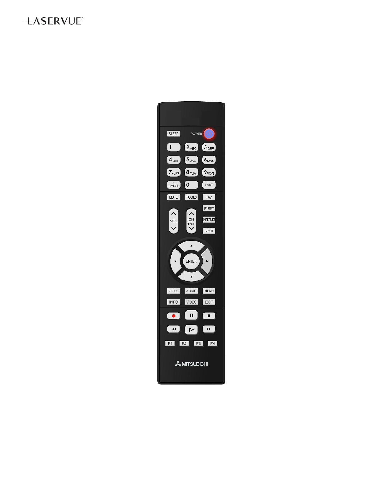
REMOTE CONTROL
NOTE: The Remote Controls differ between Type 1 and the Type 2 models.
DLP® HOME CINEMA
TYPE 1
V45C V45 V45CA
WD-73C11 WD-73640 WD-73CA1
REMOTE CONTROL USE FOR SERVICE
Many service functions and adjustments are accessed using the Remote Control. The Type 1 remote does not have
buttons such as PLAY, FWD and RVW that are associated with operating connected devi ces. Service Pro c edures are
described assuming a Type 1 remote is being used. However, if a Type 2 remote is being used, buttons can optionally
be substituted as follows:
TYPE 2
V45+ V45++ V45CB
WD-73740 WD-73840 WD-82CB1
WD-82740
WD-82840
WD-92840
Type 1
V45C / V45 / V45CA
V45+ / V45++ / V45CB
TYPE1 TYPE 2
<2> <2> or <PLAY>
<CH-UP> <CH-UP> or <FWD>
<CH-DOWN> <CH-DOWN> or <RVW>
Type 2
55
Page 56

DLP® HOME CINEMA
OPTION MENU
OPTION MENU
1. Press the <MENU> button on the remote control.
2. Press the buttons <2-4-7-0>. The screen will display the Option Menu.
Option Menu
<MENU><2-4-7-0>
Initialize
Power Restore OFF
Production Mode OFF
Digital Signal Strength <1~9>
NetCommand Software Vxx xxx.xx
Total hours of use 0
SERVICE LEVEL INITIALIZATION
Service Level Initialization is used to restore all customer menu, video and audio settings to the original fa ctory default
condition.
1. Enter the Option Menu <MENU><2-4-7-0>
2. Select “Initialize” and <ENTER>.
Option Menu
<MENU><2-4-7-0>
Initialize
Power Restore OFF
Production Mode OFF
Digital Signal Strength <1~9>
NetCommand Software Vxx xxx.xx
Total hours of use 0
56
Page 57

DIGITAL SIGNAL INFORMATION
Information on the currently selected digital channel can be displayed on screen.
1. Enter the Option / Service Menu <MENU><2-4-7-0>.
Option Menu
<MENU><2-4-7-0>
Initialize
Power Restore OFF
Production Mode OFF
Digital Signal Strength <1~9>
NetCommand Software Vxx xxx.xx
Total hours of use 0
DLP® HOME CINEMA
1. Select “Digital Signal Strength” and <ENTER>.
Digital Signal Information
“Digital Signal Strength” <ENTER>
Tuner
Frequency(MHz) 749
Signal Level <1~9>
Modulation 8VSB Air
Carrier Lock Locked
SNR 29.09
Correctable errors 0
Un Correctable errors 0
57
Page 58

DLP® HOME CINEMA
SERVICE ADJUSTMENTS
Service Adjustments include Adjustment Procedures and Data Transfer Functions.
Electrical Adjustments (there are no mechanical adjustments)
• Horizontal and Vertical Centering Adjustment
• Index Delay Adjustment
• Geometry Alignment
• Data Transfer Functions
Test Equipment and Test Patterns
• Remote Control
• Internally generated Test Patterns
• No external test equipment or pattern generators are required.
SERVICE MENU
The Service Menu is used for all service adjustments.
Service adjustments can only be performed using the remote control.
1. Activating the Service Menu
1. Press the <MENU> button on a remote control. (The Customer Menu will app ear.)
2. Press the buttons <2-4-5-7>. (The Service Menu will appear. )
2. Test Pattern Activation
When in the Service Menu, press the <2> or <
indication will be displayed initially). Use <CH-UP/CH-DOWN> or <
<2> or <
Press <2> or <
3. Adjustment Overview—Specific adjustment procedures follow.
1. When in the Service Menu use the <VIDEO> button to toggle to adjustment desired indicated by the
number and abbreviation displayed on screen.
2. For Geometry, from the Service Menu press <0> and select “Manual Geometry Alignment” <ENTER>.
4. Adjusting Data
After selecting an adjustment item, use the Navigation arrows or other button s indicated in the adjustment
procedure to perform the adjustment.
5. Saving Data
Press <ENTER> to save the adjustment data. The menu display will turn red for approximately one second.
Note: If the circuit adjustment mode is terminated without pressing <ENTER>, changes in adjustment data
are not saved.
6. Exiting the Service Menu
Press <EXIT> to quit.
> a second time and use <CHAN-UP/CHAN-DOWN> or </> to access additional patterns.
> again to toggle back to the previous patterns.
Service Menu
<MENU> <2-4-5-7>
SERVICE
TVM
1. HVPOS
> key on the remote to activate the internal test patterns (no
-3
4
/> to toggle between patterns. Press
58
Page 59

DLP® HOME CINEMA
ADJUSTMENT PROCEDURES
Horizontal and Vertical Position Adjustment
1. Enter the Service Menu <MENU><2-4-5-7>.
4
<> x2.
<> x2
Data (HPOS)
Data (VPOS)
> buttons to center the display.
2. Select the Geometry Test Pattern shown <2> <CH-DOWN>or
3. If necessary, use the <VIDEO> button to select the adjustment, “1.HVPOS”.
4. After selecting the HVPOS adjustment item, use the Navigation <
5. Press <ENTER> to save the adjustment data. The on-screen display will flash red while the data is sa ved.
Vertical & Horizontal Position Adjustment
<MENU><2-4-5-7> <2> <CH-DOWN> or
Adjustment
SERVICE
TVM
1.HVPOS
-3
Index Delay Adjustment (Perform after color wheel replacement)
1. Enter the Service Menu <MENU><2-4-5-7>.
2. Select the Ramp Pattern shown below <2> <CH-DOWN> or
3. Use the <VIDEO> button to select the adjustment, “60.IDL”.
4. After selecting the IDL adjustment item, use the Navigation <
bars for the smoothest transition from dark to bright.
5. Press <ENTER> to save the adjustment data. The on-screen display will turn red while the data is saved.
Index Delay Adjustment
<MENU><2-4-5-7> <2> <CH-DOWN> or <> x3 <VIDEO>
Adjustment
SERVICE
TVM
60.IDL
201
<> x3.
Data
> buttons to adjust the ramp pattern color
59
Page 60

DLP® HOME CINEMA
Manual Geometry Alignment
1. Entering the Manual Geometry Alignment Mode
1. Activate the Service Mode <MENU><2-4-5-7>.
2. From the Service Menu, press the <0> button. The Data Transfer & Geometry Menu will appear.
3. Use the <
Alignment Pattern will appear.
Type 2 Data Transfer & Geometry Menu <MENU><2-4-5-7><0>
RESTORE ENGINE DATA FROM BACKUP
RESTORE GEOMETRY DATA FROM BACKUP
MANUAL GEOMETRY ALIGNMENT
RESTORE INDEX DELAY
SAVE ENGINE AND GEOMETRY SETTING TO BACKUP
BACKUP AND RESTORE ISF SETTINGS
RED ONLY AND GREEN ONLY
> buttons to select “MANUAL GEOMETRY ALIGNMENT” <ENTER>. The Manual Geometry
Manual Geometry Alignment
<MENU><2-4-5-7><0> “MANUAL GEOMETRY ALIGNMENT”<ENTER>
60
Page 61

DLP® HOME CINEMA
C
r
2. Manual Geometry Alignment
Note: Upon entering the Manual Geometry Alignment Mode the first time, the geometry may appear distorted
because all factory geometry correction is automatically disabled. Press <EXIT> to quit and re-ena ble
the factory geometry correction. Pressing <1> <ENTER> and <EXIT> will cause the TV to operate with
out factory geometry correction (distortion will be present).
Note: At any time the original factory geometry data can be restored from backup:
From the Data Transfer & Geometry Menu <MENU><2-4-5-7><0>, select “RESTORE
GEOMETRY DATA FROM BACKUP” <ENTER>.
+
urso
+
Adjustm ent Points
(16 Total)
Align Cursor + Flush With Bezel Edge
Phase 1 - 16 Point Geometry Alignment
1. 16 Adjustment Points are indicated by white dots around the edge of the raster. The adjustment position is
indicated by a + cursor.
2. Starting from the upper left corner, use the <
flush with the bezel as a reference. See example above.
Note: Only the cursor will move. The Geometry Pattern will not change.
3. After adjusting each point, use the <CH-UP> or <
and repeat until all 16 points have been adjusted.
4. After all 16 points are adjusted and the cursor is returned to the original starting point, press <ENTER> the n
<EXIT>. Correction will be automatically calculated and saved and the Manual Geometry Alignment will be
terminated.
5. Re-activate the Manual Geometry Alignment. The geometry pattern will appear with the corrections applied. If
Geometry is acceptable, press <EXIT> to quit. To touchup the raster geometry, proceed to Phase 2.
Phase 2 - Geometry Touch-up Alignment
1. If additional correction is necessary after performing the Manual Geometry Alignment, re-enter the Manual
Geometry Alignment mode.
2. Use the <CH-UP/CH-DOWN> or <
3. Use the <
point. Note: Only the cursor will move. The Geometry Pattern will not change.
4. Press the <INFO> button to apply the correction. The Geometry Pattern will now show the correction.
5. Repeat steps 2, 3 and 4 as needed.
6. Press <ENTER> then <EXIT> to save your changes. The Manual Geometry Alignment will be terminated.
7. To proceed to Phase 3, re-activate the Manual Geometry Alignment.
> buttons to indicate the direction and amount of correction necessary at the particular
/> buttons to shift the cursor to the point needing correction.
> buttons to align the + at each point in a straight line,
> button to shift the cursor to the next point clockwise
61
Page 62

DLP® HOME CINEMA
Phase 3 - 4:3 and 16:9 Alignment
1. With the Manual Geometry Alignment activated, press <VIDEO> to enter the 4:3 Alignment Mode. The pattern below will be displayed.
Note: Pressing <VIDEO> will toggle between the 4:3,16:9 (top, top-center, center & bottom) and 16 Point Ge-
ometry Alignment modes.
2. In the 4:3 Alignment Mode, pressing <CH-UP/CH-DOWN> or <
displayed with 11 preset amounts of correction. Toggle through them until you find the one with the straightest Blue 4:3 Lines. It may help to count the patterns as you cycle through them. When you find the pattern
with the straightest Blue 4:3 Lines, press <VIDEO>. The Top 16:9 Alignment Mode will then be activated as
indicated by the Top Red 16:9 Line displayed in the pattern.
4:3 MODE
/> will cause the geometry pattern to be
Select Straightest Blue Lines
3. In the 16:9 Alignment Mode, pressing <CH-UP/CH-DOWN> or </> will cause the geometry pattern to be
displayed with 15 different preset amounts of correction to the Red Line. Toggle through them until you find
the one with the straightest Red Line. Again, count the patterns as you cycle through them. When you find
the pattern with the straightest line, press <VIDEO>. The Top-Center Red Line will be displayed in the pattern.
4:3 MODE
Select Straightest Red Line (Top)
62
Page 63

DLP® HOME CINEMA
4. Repeat the process of pressing <CH-UP/CH-DOWN> or </> to display the 15 different preset amounts
of correction to the Top-Center Red Line. When you find the pattern with the straightest line, press
<VIDEO> to proceed to the Center Red Line. Repeat the process for the Center Line, followed by the Bottom Line. Press <ENTER> then <EXIT> to exit and save the 4:3 and 16:9 data.
5. Select the Geometry Test Pattern (See HVPOS). If Geometry is acceptable, press <EXIT> to quit.
Select Straight est Red Line ( Top- C ent er)
Select Strai ght est Red Line (Cent er)
4:3 MODE
Select Straightest Red Line (Bottom)
63
Page 64

DLP® HOME CINEMA
DATA TRANSFER FUNCTIONS
Data Transfer
Service Data is duplicated and stored in separate EEPROMs in two locations.
PWB-MAIN - Working Service Data for TV operation
OPTICAL ENGINE - Backup Service Data
The Optical Engine also includes data for the Index Delay setting for color wheel timing determined at the factory.
The PWB-MAIN also includes User and/or ISF settings. The User/ISF data is not backed up on the Engine. However if used, it can
be backed up onto a USB flash drive.
Data Transfer Procedures should be followed…
After PWB-MAIN Replacement:
1. Restore Engine Data From Backup.
2. Restore Geometry Data From Backup.
3. Restore ISF Settings From Flash Drive
After OPTICAL ENGINE Replacement:
1. Restore Index Delay.
2. Save Engine and Geometry Setting to Backup
Geometry Adjustments).
. (Only if backup USB flash drive is available).
(After performing any necessary H&V Position and
Data Transfer Procedure:
1. Enter the Service Mode <MENU><2-4-5-7> Select the Data Transfer & Geometry Menu <0>
Note: Besides MANUAL GEOMETRY ALIGNMENT, six data transfer choices are listed on screen.
RESTORE ENGINE DATA FROM BACKUP - copies backup factory adjustments HVPOS, White Balance
RESTORE GEOMETRY DATA FROM BACKUP -
RESTORE INDEX DELAY -
SAVE ENGINE AND GEOMETRY SETTING TO BACKUP - copies all working data from the PWB-MAIN
BACKUP AND RESTORE ISF SETTINGS - allows the ISF (ADV) video settings to be backed up and
RED ONLY AND GREEN ONLY - displays the video in red or green only during ISF Calibrat ion.
2. Use the <
3. Follow on-screen instructions if given.
4. Press <EXIT> to quit.
Data Transfer & Geometry Menu <MENU><2-4-5-7><0>
RESTORE ENGINE DATA FROM BACKUP
RESTORE GEOMETRY DATA FROM BACKUP
MANUAL GEOMETRY ALIGNMENT
RESTORE INDEX DELAY
SAVE ENGINE AND GEOMETRY SETTING TO BACKUP
BACKUP AND RESTORE ISF SETTINGS
RED ONLY AND GREEN ONLY
Warning: Only use “SAVE ENGINE AND GEOMETRY SETTING TO BACKUP”
after Optical Engine Replacement.
and Index Delay from the Optical Engine to the PWB-MAIN.
copies backup factory Geometry Alignment data from
the Optical Engine to the PWB-MAIN.
copies factory Index Delay Adjustment data from the Optical Engine to the
PWB-MAIN.
into backup memory on the Optical Engine.
restored using an external USB flash drive.
> buttons to select the item and press <ENTER>.
64
Page 65

DLP® HOME CINEMA
RESET / INITIALIZATION
SERVICE TIP:
Many symptoms that are customer generated, intermittent or cannot be verified can be resolved by using the various
Reset and Initialization options. Before visiting the customer’s home ask the customer to 1st perform a System Reset. If
this does not resolve the issue, they can perform an A/V Reset. Then, if necessary, perform a user level Initialization.
The customer should be made aware when settings and/or options will be reset. For more information, see the chart
below.
Reset Name When to use How to use Resulting Action
Remote Control
Reset
TYPE 1 Only
Returns the remote control to normal
operation.
1)
Press and hold the <POWER> button until it flashes twice
then release the button.
2)
Enter the code <0-0-0-0-0>. The <POWER> button will flash
twice
The remote control is reset.
Remote Control
TV Layer Reset
TYPE 2 Only
Remote Control
TV Volume/
Mute functions
A/V Memory
Reset, by individual input
A/V Reset, all
inputs
System Reset To reset the TV when it does not turn
Returns the remote control TV layer
to normal operation.
Returns the volume and mute functions of the remote control to TV volume and mute for TV, Cable/Sat,
VCR and DVD layers after the Audio
Lock for AV Receiver feature has
been used.
When the audio or video performance
or settings for a single input seem to
be incorrect.
When the audio or video performance
or settings for more than one input
seem to incorrect.
on or off, does not respond to the
remote control, front panel buttons or
has other unusual symptoms.
1)
Select the remote control TV mode.
2)
Press and hold the <POWER> button until it flashes twice
then release the button.
3)
Enter the code <0-0-9-3-5>. The <POWER> button will flash
twice
1)
Select the remote control TV mode.
2)
Press and hold the <POWER> button until it flashes twice
then release the button.
3)
Enter the code <9-9-3>< VOL >. The <POWER> button
will flash four times.
<MENU> “Audio/Video” “AV Reset” <ENTER> All Audio and Video settings
While viewing the TV, press the front panel buttons <INPUT> +
<VOL > at the same time and hold for 10 sec.
Press the <POWER> button on the front panel and hold it for 8
seconds.
The remote control TV layer
is reset.
The remote will now operate
the TV's volume and mute
when the slide switch is in
the TV, CABLE/SAT, VCR
or DVD positions.
for the individual input are
reset except for the Listen
To, Language, Balance and
Closed Caption settings.
All Audio and Video settings
are reset to the factory default settings. No other
menu options are changed.
TV Micro Re-boots. Note:
The changes made during
the current TV-On period
may be lost. All other previous user settings are not
lost.
Initialize User
Level
Initialize - Service Level
V-Chip Password Bypass
Unlock Front
Panel
To reset all customer settings except
V-Chip
To reset all customer settings <MENU><2-4-7-0> "INITIALIZE" <ENTER> All customer menu options
If V-Chip password is not known Press <LAST>+<9> at the same time. Password will be bypassed.
To unlock the front panel if it has
been locked in the V-Chip Menu.
Press <MENU><1-2-3><ENTER> All customer menu options
Press and hold the front panel <ENTER>
button for 8 seconds.
and A/V settings except VChip & locked ISF are reset
to factory default.
and A/V settings are reset
to factory default.
If in the V-Chip menu, enter
a new password.
Front Panel becomes operational. Other V-Chip
settings not changed. Note:
Cannot be performed while
in the Low Power mode and
the set is Off.
65
Page 66

DLP® HOME CINEMA
LED INDICATIONS AND SELF DIAGNOSTICS
The front panel Status LED provides an indication of the set’s operation and the possible cause of a malfunction.
NORMAL INDICATIONS
STATUS LED Indication Condition
Off Off (Standby)
Green Power On
Slow Blinking Green Power Off with Timer Set. Power On normally
Fast Blink Green 80 seconds after Power Off Power Off Lamp cooling. Wait for blinking to
stop to Power On.
Fast Blinking Green 1 to 3 minutes after Power
Restored from AC interrupt, Power On, System
Reset or Software update.
ABNORMAL INDICATIONS
STATUS LED Indication Condition
Steady Red Lamp Failure (See Error Code 66)
Steady Yellow DMD Temperature Excessive
Blinking Yellow Lamp Cover Open (See Error Code 32)
Blinking Red then Blinking Yellow Circuit Failure (See Self Diagnostics)
Boot-up. Wait for blinking to stop to Power On.
SELF DIAGNOSTICS
A blinking red and yellow Status LED will indicate an Error Code that can help determine the cause of a circuit
failure.
The number of Red blinks indicates the value of the MSD (tens digit) of the Error Code.
The number of Yellow blinks indicates the value of the LSD (ones digit) of the Error Code.
Example: If the Error Code is “37”, the LED will continuously blink Red three times, followed by blinking Yellow
seven times.
See the following page for a list of Error Codes.
To perform a System Reset, press and hold the Power button for 10 seconds. Or, unplug the set for 10 seconds
then restore power.
Number of Red Blinks Number of Yellow Blinks
3 7
Error Code: 37
66
Page 67

DLP® HOME CINEMA
ERROR CODES
Error Codes, descriptions and the most likely cause of failure are listed below:
ERROR CODES
Code Description Most Likely Cause
Loss of 12V from PWB-POWER to Engine /
17 I2C Communication loss between TV Micro and Engine
Engine will not accept data
18
(ASIC-READY signal from Engine is not detected)
Lamp Cover is open.
32*
Lamp turns Off while the TV is playing.
34**
66**
Lamp Failure
Lamp Enable signal from engine is lost.
36 Exhaust Fan rotation not detected Check Exhaust Fan / Check J4 circuitry
37 Engine (DMD) fan rotation not detected Check DMD Fan / Check J5 circuitry
42 Sirocco fan (Lamp fan) rotation not detected Check Sirocco Fan / Check J8 circuitry
44 LVDS cable between PWB-MAIN and Engine not detected Check LVDS Cable & circuitry
48 PON-SHORT 3.3V or 5V switched supply short PWB-MAIN Failure
57 Ballast communication problem (ballast to chassis)
16 LAMP-EN Detection
Lamp did not turn on at P-ON sequence
(No Lamp inserted)
(Disconnected cable between ballast and lamp)
(Lamp-Enable goes to PWB-MAIN but not to Ballast)
Check PE & PE2 circuitry
Engine Failure, PWB-MAIN Failure
LDVS circuitry
Engine Failure
Check CD connector
Lamp Cartridge Failure
Loss of 340V from PWB-POWER to Ballast /
Check PL & CJ1 circuitry
Loss of communications between PWB-MAIN
and Ballast / Check FB & CJ3 circuitry
Ballast Failure
Check Color Wheel / Check J6 & J7 circuitry /
Engine Failure
Check CJ4 circuitry
No Lamp Inserted.
HV connection or lead wire to lamp.
Lamp Cartridge Failure
* Error Code 32 is indicated by a flashing Yellow Status LED. The code is stored in the Error co de Log. See below.
** Error Codes 34 & 66 are indicated by a steady Red Status LED. The code is stored in the Error code Log. See
below.
ERROR CODE LOG
The Error Code Log can be used to retrieve the code for an error that occurred in the past.
To access the Error Code Log: Press < MENU> <3-5-6-4>
Error Code Log Definitions
PAGE - Current page number
CURRENT TIME - total hours of operational
use.
USAGE TIME - usage hours when the error
occurred.
CODE - the specific Error Code that oc-
curred.
STATUS: HAPPENED - Indicates an error
was recorded.
Press <CANCEL> to erase the Log.
NOTE: The Error Code Log is intended as a ref-
erence tool and is not meant to be used as a final
determination of a defective part.
Error Code Log
<MENU><3-5-6-4>
***** PAGE (001/001) *****
CURRENT TIME: 01455 HOURS
USAGE TIME CODE STATUS
00413 HRS 44 HAPPENED
00716 HRS 57 HAPPENED Press Up to Previous Page
Press Down to Next Page
Press Right to Top Page
Press Left to Last Page
Press CANCEL to Erase
Press MENU to Exit
67
Page 68

DLP® HOME CINEMA
SPEAKER TRANSDUCER AND SPEAKER FREQUENCY TEST (V45++ Only)
These procedures will test the TV’s speakers using an internal tone generator.
1. Press the <MENU> button on the remote control. The Customer Menu will appear.
2. Press the <2-4-5-7> buttons. The Service Menu will appear.
3. Press the <0> button. The Data Transfer & Geometry Menu will appear. See below.
4. Use the <
Test Menu will be displayed. A tone will automatically cycle from one speaker to the next as indicated on
screen. Follow the instructions to manually cycle the tone.
5. From the Data Transfer & Geometry Menu, use the <
The Speaker Frequency Test Menu will be displayed. A tone will automatically cycle from one frequency
to the next as indicated on screen. Follow the instructions to manually cycle the frequency tone.
6. Press <EXIT> to exit.
Data Transfer & Geometry Menu <MENU><2-4-5-7><0>
RESTORE ENGINE DATA FROM BACKUP
RESTORE GEOMETRY DATA FROM BACKUP
MANUAL GEOMETRY ALIGNMENT
RESTORE INDEX DELAY
SAVE ENGINE AND GEOMETRY SETTING TO BACKUP
SPEAKER TEST
SPEAKER FREQUENCY TEST
BACKUP AND RESTORE ISF SETTINGS
RED ONLY AND GREEN ONLY
> buttons to select “SPEAKER TEST” and press <ENTER>. The Speaker Test Transducer
> buttons to “SPEAKER FREQUENCY TEST.”
68
Page 69

CIRCUIT BLOCK DIAGRAMS
DLP® HOME CINEMA
69
Page 70

DLP® HOME CINEMA
CIRCUIT BLOCK DIAGRAMS
70
Page 71

DLP® HOME CINEMA
71
Page 72

DLP® HOME CINEMA
72
Page 73

DLP® HOME CINEMA
73
Page 74

DLP® HOME CINEMA
74
Page 75

 Loading...