

Page 1
Version 3.0 10/13/11
2011
Service
Manual
DLP PROJECTION HDTV
V45C
V45 V45CA
WD-73C11 WD-73640 WD-73CA1
V45+
V45++ V45CB
WD-73740 WD-73840 WD-82CB1
WD-82740
WD-82840
WD-92840
CAUTION:
Before servicing this chassis, it is important that the service person read the "SAFETY PRECAUTIONS" and
"PRODUCT SAFETY NOTICE" contained in this manual.
SPECIFICATIONS
• Power Input : AC 120V, 60Hz
• Light Engine : DLP™ (1080p)
• Light Source : VIP Lamp
• Antenna Input : RF 75unbalanced
• Tuning : NTSC/ATSC/QAM
: Analog Cable - 1~125
Digital Cable - 1~135
• Speakers : 10W x 2 (except V45++)
: 2W x 16 (V45++)
• See Page 5 for additional specifications.
• Design specifications are subject to change without notice.
• Analog Input
Level (RCA Type)
Y/Video: 1.0 Vp-p, Cr, Cb: 700mVp-p
75 unbalanced
: AUDIO IN JACK (RCA Type)
-4.7dBm 43k unbalanced
• Analog Output : AUDIO / SUBWOOFER OUT JACK
Level (RCA Type)
-4.7dBm 4.7kunbalanced
• Digital : AC-3/PCM Digital Audio Output
Inputs/Outputs (RCA Type)
: HDMI™
:
: PC - use HMDI™
:
: Ethernet (V45CB, V45+, V45++)
: Bluetooth (V45++)
: Composite/Component
USB
Wired IR Input/Output (V45++)
MITSUBISHI ELECTRIC VISUAL SOLUTIONS AMERICA, INC.
9351 Jeronimo Road, Irvine, CA 92618-1904
Copyright © 2011 Mitsubishi Electric Visual Solutions America, Inc.
All Rights Reserved
Page 2

Page 3

MODELS: WD-73640 / WD-73740 / WD-73840 / WD-73C11 / WD-73CA1 /
WD-82740 / WD-82840 / WD-82CB1 / WD-92840
CONTENTS
INTRODUCTION .................................................................................................................................. 5
Dimensions, weight, power usage, etc. ............................................................................................ 5
PRODUCT SAFETY NOTICE .............................................................................................................. 5
SAFETY PRECAUTIONS .................................................................................................................... 6
DISASSEMBLY & PARTS REPLACEMENT ...................................................................................... 7
Back Cover Removal ........................................................................................................................ 7
Chassis Removal ............................................................................................................................ 8
Rear Terminal Cover Removal ......................................................................................................... 8
PWB-POWER Removal ................................................................................................................... 9
PWB-MAIN Removal ........................................................................................................................ 9
PWB-BALLAST Removal ............................................................................................................... 10
Optical Engine Assembly Removal & Disassembly ....................................................................... 10
Optical Engine Replacement .......................................................................................................... 13
Projection Lens Replacement ........................................................................................................ 14
Color Wheel Replacement ............................................................................................................. 15
Screen Replacement ...................................................................................................................... 16
Mirror Replacement ........................................................................................................................ 20
SERVICE PROCEDURES ................................................................................................................. 23
Remote Control .............................................................................................................................. 23
Option Menu ................................................................................................................................... 24
Reset and Initialization ................................................................................................................... 26
LED Indications & Self Diagnostics ................................................................................................ 27
Error Codes .................................................................................................................................... 28
Error Code Log ............................................................................................................................... 28
Sound Projector Transducer Test .................................................................................................. 29
Service Adjustments
Equipment & Test Signals ..................................................................................................... 30
Service Menu ........................................................................................................................ 30
Horizontal & Vertical Position Adjustment ............................................................................. 31
Index Delay Adjustment ........................................................................................................ 31
Manual Geometry Alignment ................................................................................................. 32
Data Transfer Functions ................................................................................................................. 36
Using Lead Free Solder ................................................................................................................. 37
Chip Parts Replacement ................................................................................................................ 38
REPLACEMENT PARTS ................................................................................................................... 39
Safety Critical Parts Designation .................................................................................................... 39
Fuse Replacement Warning ........................................................................................................... 39
Parts Quick Reference ................................................................................................................... 40
Service Parts List ........................................................................................................................... 41
Screen Parts ................................................................................................................................... 46
Mirror Kits & Preparation ................................................................................................................ 48
CIRCUIT BLOCK DIAGRAMS .......................................................................................................... 50
SCHEMATIC DIAGRAMS ................................................................................................................. 56
....................................................................................................................... 30
Version 3.0
Page 3
Page 4

MODELS: WD-73640 / WD-73740 / WD-73840 / WD-73C11 / WD-73CA1 /
WD-82740 / WD-82840 / WD-82CB1 / WD-92840
Version 3.0
Digital Light Processing®, Digital Micro Mirror Device and DLP® are Trademarks of Texas Instruments.
HDMI, the HDMI logo and High-Definition Multimedia Interface are trademarks or registered trademarks of HDMI Licensing, LLC..
Page 4
Page 5
MODELS: WD-73640 / WD-73740 / WD-73840 / WD-73C11 / WD-73CA1 /
WD-82740 / WD-82840 / WD-82CB1 / WD-92840
INTRODUCTION
This service manual provides service instructions for the V45C, V45, V45CA, V45+, V45CB and V45++ chassis
types. The specific models for each chassis type, dimensions and weight are listed below. Service personnel should
read this manual thoroughly before servicing these chassis.
This service manual includes:
1. Disassembly & replacement instructions for cabinet and chassis components.
2. Replacing the Lenticular Screen, Fresnel Lens and Mirror.
3. Initial setup and troubleshooting.
4. Service adjustments.
5. Using lead free solder.
6. Chip parts replacement procedures.
7. Replacement part Instructions
8. Replacement parts list
9. Circuit block diagrams
10. Schematic diagrams
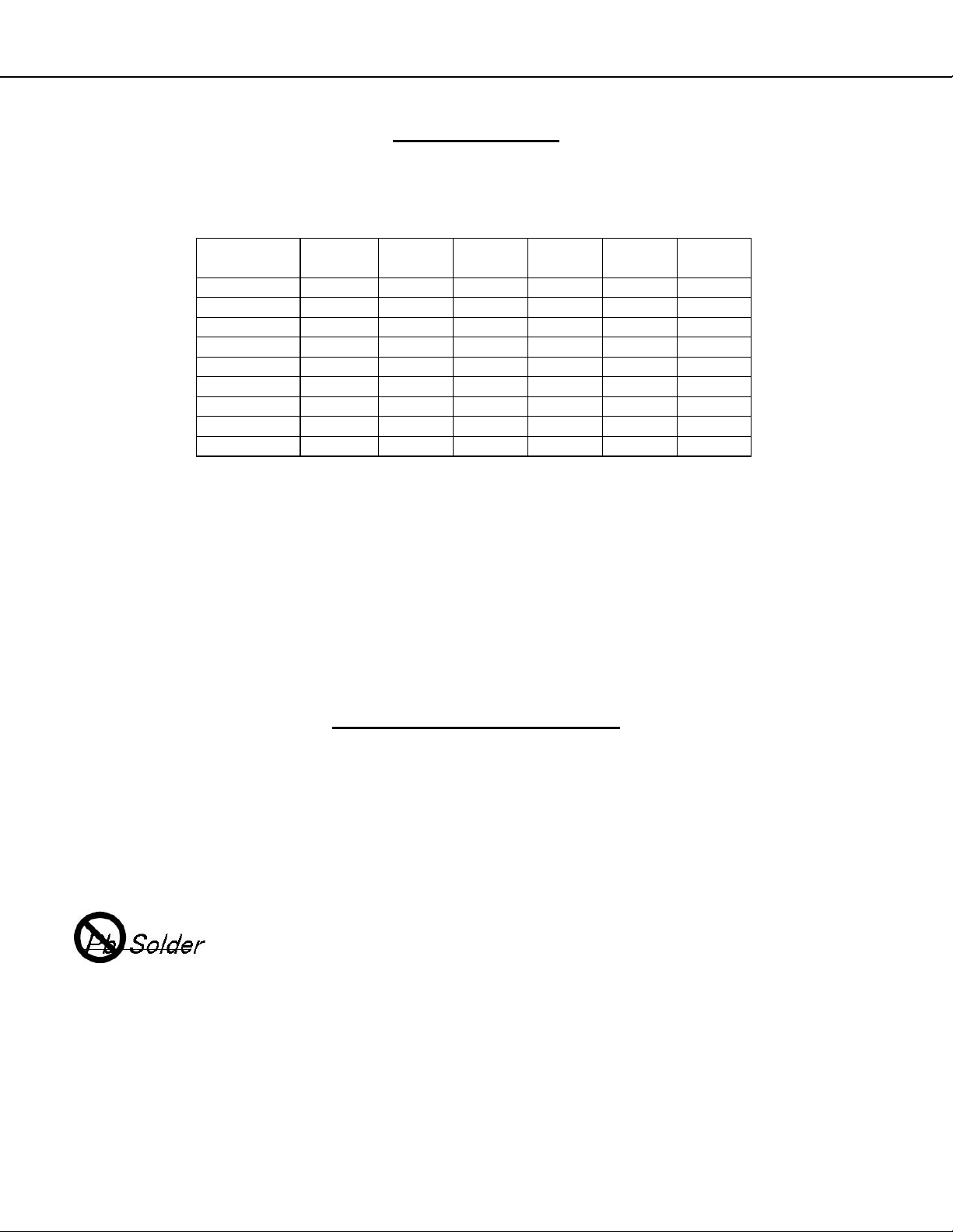
MODEL CHASSIS HEIGHT WIDTH DEPTH WEIGHT
WD-73C11 V45C 43.6" 65.0" 17.5" 77.9 lbs 260W
WD-73640 V45 43.6" 65.0" 17.5" 77.9 lbs 260W
WD-73CA1 V45CA 43.6" 65.0" 17.5" 77.9 lbs 270W
WD-73740 V45+ 43.6" 65.0" 17.5" 77.9 lbs 270W
WD-82740 V45+ 48.7" 73.3" 19.8" 129.9 lbs 270W
WD-82CB1 V45CB 48.7" 73.3" 19.8" 129.9 lbs 270W
WD-73840 V45++ 43.6" 65.2" 17.5" 83.6 lbs 290W
WD-82840 V45++ 48.7" 73.2" 19.8" 133.6 lbs 275W
WD-92840 V45++ 54.8" 82.1" 22.0" 195.1 lbs 290W
POWER
USAGE
PRODUCT SAFETY NOTICE
Many electrical and mechanical parts in television receivers have special safety related characteristics. These characteristics are often not evident from visual inspection nor can the protection afforded by them necessarily be obtained by using replacement components rated for higher voltage, wattage, etc.
Replacement parts which have special safety characteristics are identified on the schem atic diagrams and parts list
of this service manual. The replacement for any safety critical part should be identical in value and character-
istics.
Version 3.0
The PWBs used in this chassis are constructed using Lead-Free Solder. When servicing use
only recommended Lead-Free Solder. Refer to the section “Using Lead Free Solder.”
Page 5
Page 6
MODELS: WD-73640 / WD-73740 / WD-73840 / WD-73C11 / WD-73CA1 /
WD-82740 / WD-82840 / WD-82CB1 / WD-92840
SAFETY PRECAUTIONS
NOTICE:
Observe all cautions and safety related notes located inside the receiver cabinet and on the receiver chassis.
WARNING:
1. Operation of this receiver outside the cabinet or with the cover removed presents a shock hazard from the
receiver's power supplies. Work on the receiver should not be attempted by anyone who is not thoroughly
familiar with the precautions necessary when working on high volta ge equipment.
2. When service is required, observe the original lead dress. Where a short-circuit has occurred, replace those
components that indicate evidence of overheating.
SAFETY PRECAUTION
To protect your eyes, do not look directly into the lamp, or light coming directly from the lamp, lens or
mirror.
Leakage current check
Before returning the receiver to the customer, it is recommended that leakage current be measured according to the
following methods.
1. Cold Check
With the alternating current (AC) plug removed from the AC source, place a jumper across the two AC plug
prongs. Connect one lead of an ohm meter to the AC plug and touch the other lead to each exposed metal
part (i.e. antennas, handle bracket, metal cabinet, screw heads, metal overlay, control shafts, etc.), particularly
any exposed metal part that has a return path to the chassis. The resistance of the exposed metal parts having a return path to the chassis should be a minimum of 1Meg Ohm. Any resistance below this value indicates an abnormal condition and requires corrective action.
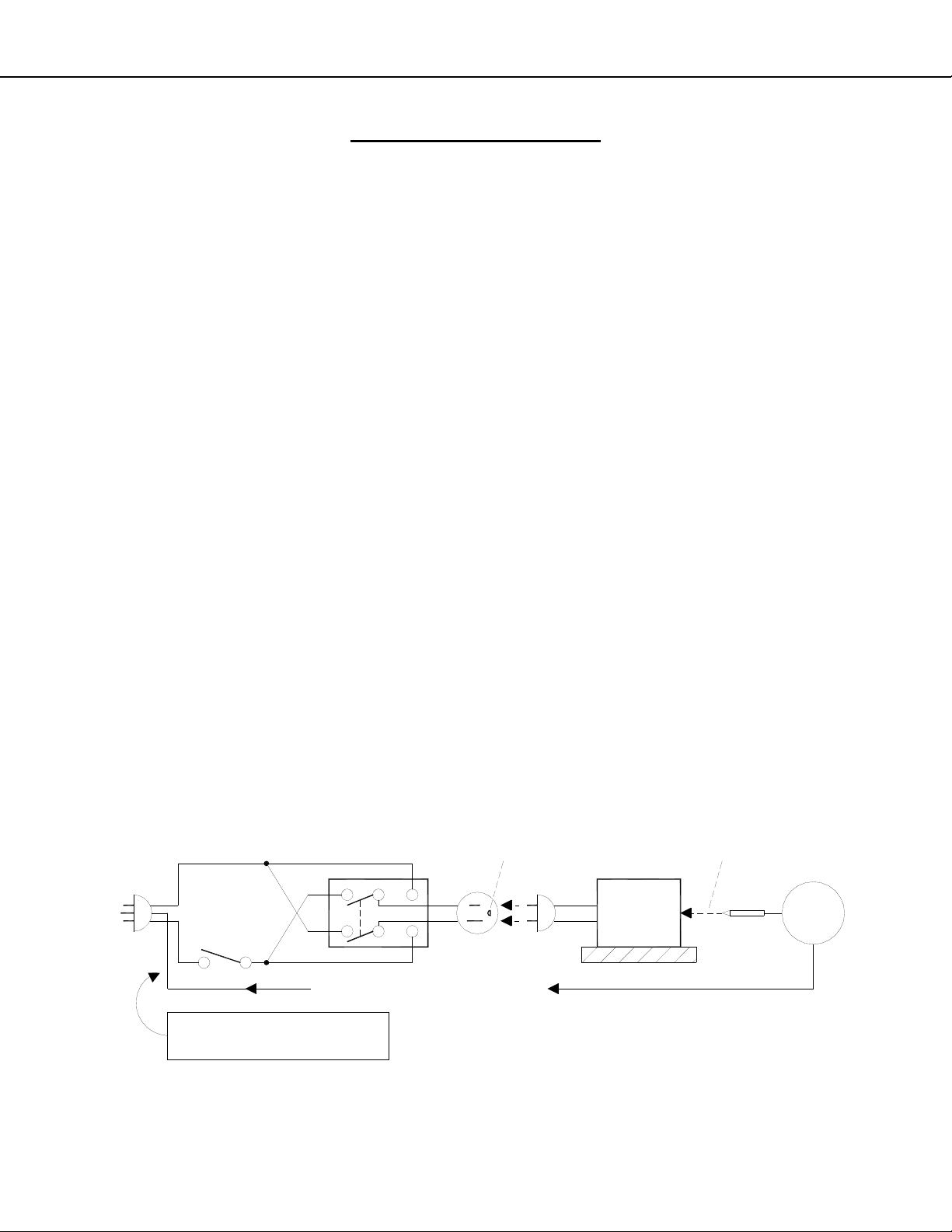
2. Hot Check ...Use the circuit shown below to perform the hot check test.
1. Keep switch S1 open and connect the receiver to the measuring circuit. Immediately after connection,
and with the switching devices of the receiver in their operating positions, measure the leakage current
for both positions of switch S2.
2. Close switch S1, energizing the receiver. Immediately after closing switch S1, and with the switching
devices of the receiver in their operating positions, measure the leakage current for both positions of
switch S2. Repeat the current measurements of items 1 and 2 after the receiver has reached therm al
stabilization. The leakage current must not exceed 0.5 milliampere (mA).
Version 3.0
S1
SUPPLY CONNECTOR GROUND
GWG - Green Wire Ground
(Earth Ground)
S2
OPEN
GROUND
L
N
Page 6
TOUCH ALL
EXPOSED
METAL PARTS
RECEIVER
AC MA
METER
INSULATED TABLE
Page 7
MODELS: WD-73640 / WD-73740 / WD-73840 / WD-73C11 / WD-73CA1 /
WD-82740 / WD-82840 / WD-82CB1 / WD-92840
DISASSEMBLY & PARTS REPLACEMENT
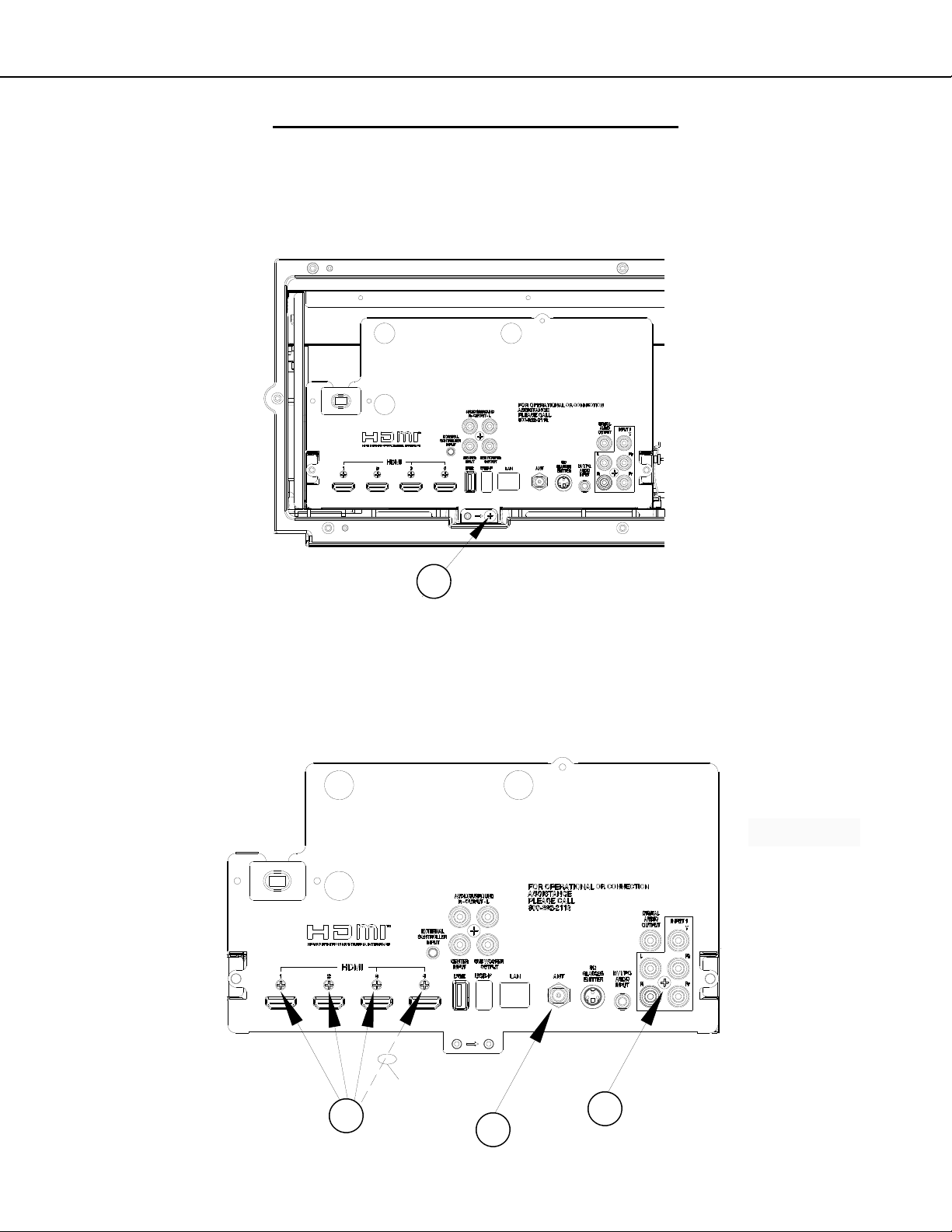
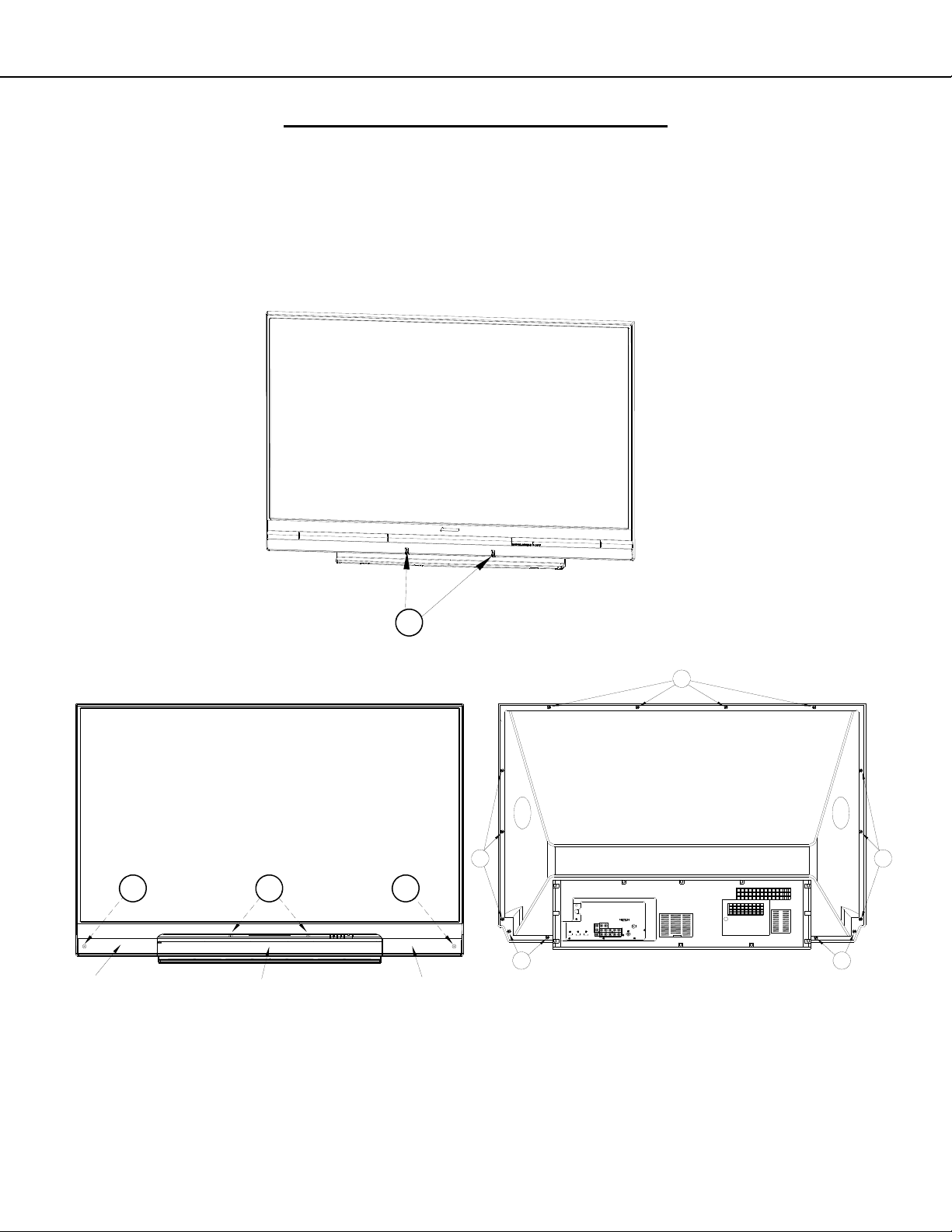
BACK COVER REMOVAL
C
Back Cover Removal
1. Remove screws (A) and remove the Lamp Cover.
2. Remove screws (B) from behind the Lamp Cover.
3. Remove Screws (C).
4. Remove the back cover from the TV.
Version 3.0
C
B
A
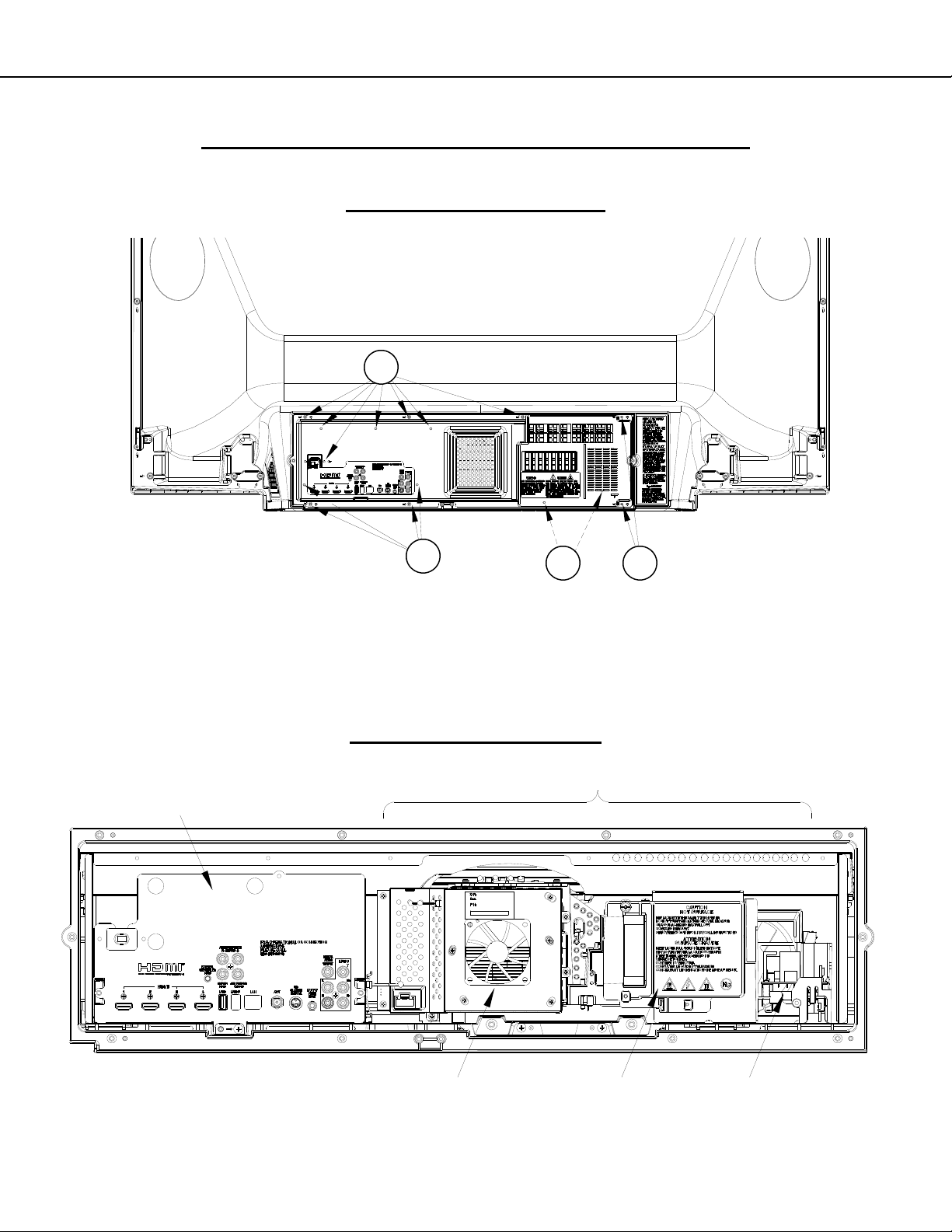
CHASSIS
ASSEMBLY LOCATIONS
OPTICAL ENGINE ASSEMBLY
DMD FAN LAMP PWB-BALLAST
Page 7
Page 8
MODELS: WD-73640 / WD-73740 / WD-73840 / WD-73C11 / WD-73CA1 /
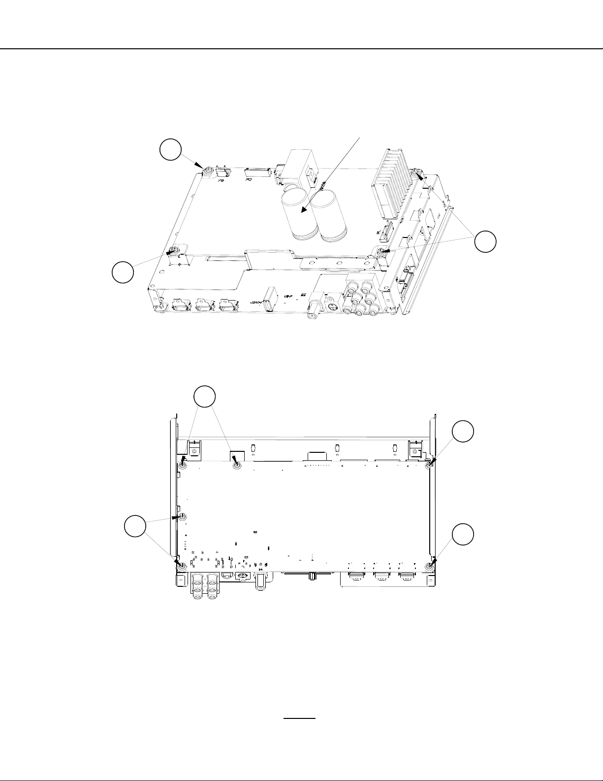
Chassis Removal
1. Remove screws (A).
2. Slide the chassis back and disconnect all cables.
3. Remove the chassis from the cabinet.
WD-82740 / WD-82840 / WD-82CB1 / WD-92840
CHASSIS - REMOVAL & DISASSEMBLY
Version 3.0
A
Rear Terminal Cover Removal (To Replace PWB-MAIN)
1. Remove nut (A) from the ANT input.
2. Remove screws (B) and (C).
3. Disconnect the connectors to the PWB-SOUND (V45++).
4. Remove the Terminal Cover from the chassis.
PWB-SOUND
CONNECTORS
(ON REAR)
V45++ Only
C
V45++ Only
B
A
Page 8
Page 9
MODELS: WD-73640 / WD-73740 / WD-73840 / WD-73C11 / WD-73CA1 /
WD-82740 / WD-82840 / WD-82CB1 / WD-92840
PWB-POWER Removal
1. Disconnect all cables from the PWB-POWER.
2. Remove screws (A).
3. Pinch the Retainer to release the PWB.
4. Lift the PWB-POWER from the chassis.
A
A
Retainer
(Pinch)
Version 3.0
A
PWB-MAIN Removal
1. Disconnect all cables to PWB-MAIN.
2. Remove screws (A) from the bottom of the PWB-MAIN.
3. Lift the PWB-MAIN from the chassis.
A
A
A
A
After PWB-MAIN Replacement
See Data Transfer in Service Procedures section.
1. V45C, V45 & V45CA: Perform “Restore Engine Data From Backup.”
2. V45+, V45++ & V45CB: Perform “Restore Engine Data From Backup” and “Restore Geometry Data From
Backup.”
V45+, V45++, V45CB IMPORTANT REPLACEMENT NOTE: If the customer has subscribed to VUDU (Internet
program provider), the customer must be instructed to contact VUDU to re-activate their account after the replacement PWB has been installed. The original PWB cannot
bishi per policy.
be installed in another TV. It must be returned to Mitsu-
Page 9
Page 10
MODELS: WD-73640 / WD-73740 / WD-73840 / WD-73C11 / WD-73CA1 /
WD-82740 / WD-82840 / WD-82CB1 / WD-92840
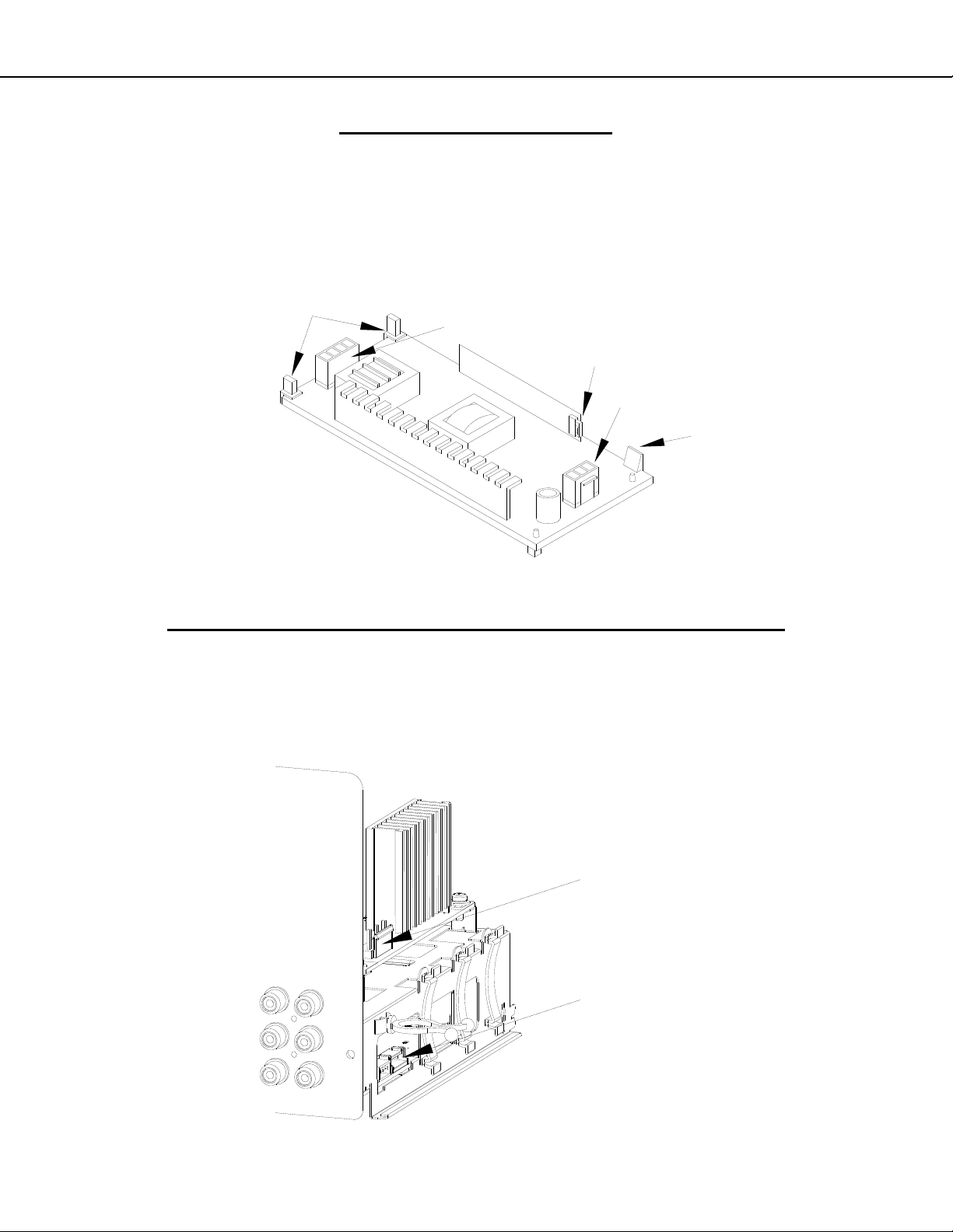
PWB-BALLAST REMOVAL
Note: To remove the PWB-BALLAST, it is not necessary to remove the Engine or Lamp Cartridge.
1. Release the Latch to lift the PWB-BALLAST up from the mounting bracket.
2. Slide the PWB-BALLAST out of the Engine Assembly.
3. Disconnect the electrical locking connectors indicated.
4. To reinstall, first connect the connectors. Then slide the PWB under the Retaining Hooks. Then press the rear
edge of the PWB down onto the guide pins to engage the latch.
RETAINING
HOOKS
CJ4 (HV to Lamp)
CJ3 (Lamp Control)
CJ1 (Lamp Power)
LATCH
Version 3.0
OPTICAL ENGINE ASSEMBLY - REMOVAL & DISASSEMBLY
OPTICAL ENGINE ASSEMBLY REMOVAL
1. Disconnect the PL connector from the side of the PWB-POWER.
2. Disconnect the FB connector from the side of the PWB-MAIN.
3. Loosen the wiring harnesses from the looms.
PL (Lamp Power)
FB
(Lamp Control and Lamp Door Switch)
Page 10
Page 11
MODELS: WD-73640 / WD-73740 / WD-73840 / WD-73C11 / WD-73CA1 /
WD-82740 / WD-82840 / WD-82CB1 / WD-92840
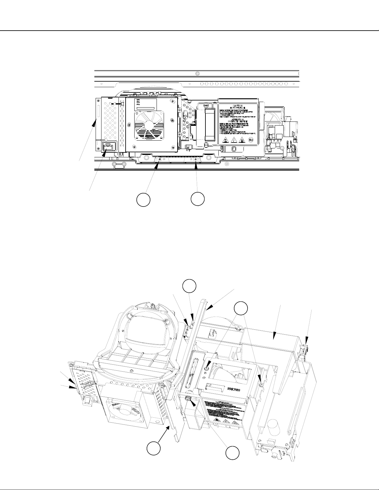
OPTICAL ENGINE ASSEMBLY REMOVAL (Continued)
1. Disconnect the PE and J12 connectors from the Engine.
2. Remove screws (A).
3. Slide the Engine Assembly back out of the cabinet.
J12 (LVDS)
Version 3.0
PE
(Engine Power)
A
A
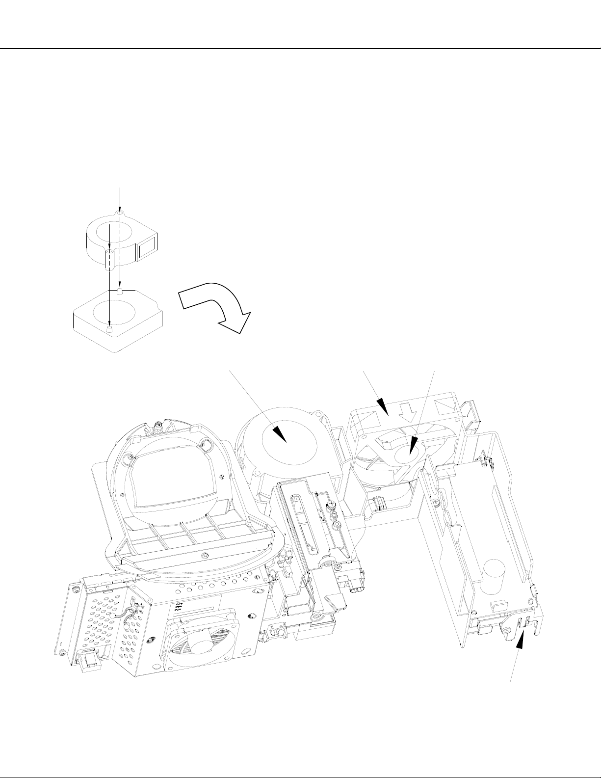
OPTICAL ENGINE ASSEMBLY - Disassembly
1. Loosen screw (A) to remove the Lamp Cartridge.
2. Remove screws (B) and the lamp top cover.
3. Remove screws (C) and the Engine Plate
4. Disconnect the Exhaust and Sirocco Fan Connectors (J4 and J8) from the back of the Engine and loosen the
wiring harnesses from the looms.
5. Release the Latches to remove the Fan Holder.
C
LATCH
ENGINE PLATE
FAN HOLDER
B
J8
(Sirocco Fan)
LATCH
J4
(Exhaust Fan)
C
Page 11
A
Page 12
MODELS: WD-73640 / WD-73740 / WD-73840 / WD-73C11 / WD-73CA1 /
WD-82740 / WD-82840 / WD-82CB1 / WD-92840
Duct Interior Components
Duct Interior Components are shown below.
Notes:
When replacing the Optical Engine, transfer all Duct and Duct Interior Components from the old Engine to the
new Engine.
The Exhaust Fan must be installed so the Label is facing inside the Duct.
The Sirocco Fan must be installed so the Label is facing up with the Flanges aligned onto the Guide Pins.
Sirocco Fan Flanges
Align Onto Guide Pins
Version 3.0
SIROCCO FAN
(Label Facing Up)
EXHAUST FAN
(Label Facing In)
Page 12
PWB-LAMP DOOR SW
Page 13
MODELS: WD-73640 / WD-73740 / WD-73840 / WD-73C11 / WD-73CA1 /
WD-82740 / WD-82840 / WD-82CB1 / WD-92840
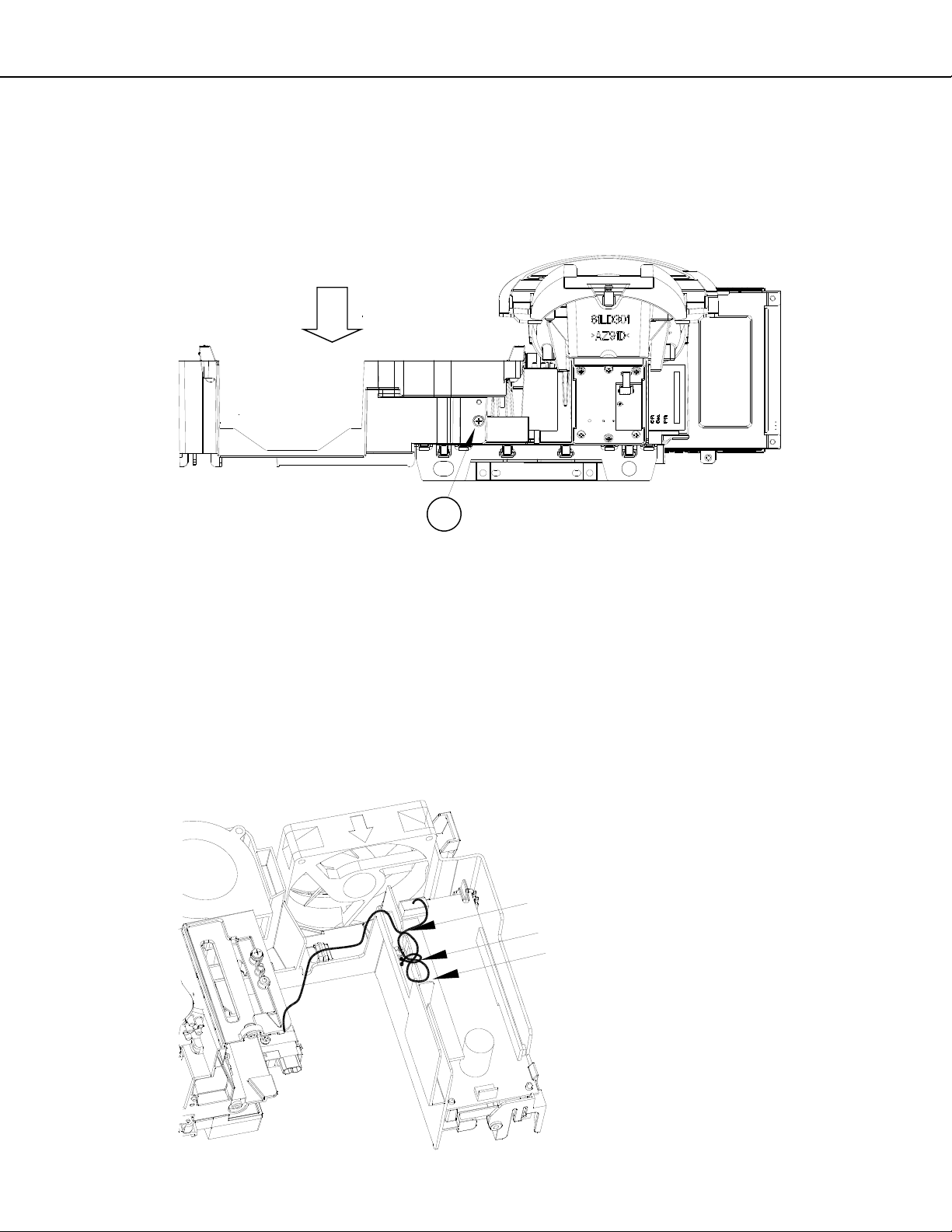
Lower Duct Removal
1. Remove the Lamp Cartridge, Top Cover, Exhaust Fan and Sirocco Fan.
2. Disconnect the HV Lamp Wiring from the Ballast and loosen it from the guides.
3. Remove screw (A) on the rear of the lower duct.
4. Carefully remove the Lower Duct from the Engine.
LOWER DUCT
Version 3.0
A
OPTICAL ENGINE REPLACEMENT
1. Install Lower Duct and components on the new Engine.
2. Connect the HV Lamp Wiring to the Ballast and dress the wiring through the guides as shown.
3. Remove the Protective Lens Cover from the face of the Lens and place it on the old Engine for return.
4. Install the Engine Assembly in the cabinet.
5. Perform the following procedures as described in the Data Transfer section of the Service Procedures:
“Restore Index Delay”
“Save Engine and Geometry Setting to Backup”
6. As necessary, perform the Horizontal and Vertical Centering Adjustment and Manual Geometry Alignment as
described in the Service Adjustments section of the Service Procedures.
HV LAMP WIRING
Dress Through Guides as Shown
Add VINAL CLAMP at center Guide.
Page 13
Page 14
MODELS: WD-73640 / WD-73740 / WD-73840 / WD-73C11 / WD-73CA1 /
WD-82740 / WD-82840 / WD-82CB1 / WD-92840
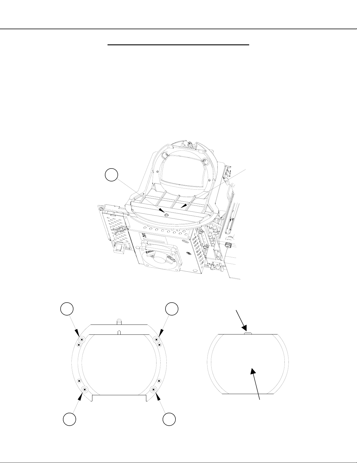
PROJECTION LENS REPLACEMENT
CAUTION: Any dust or fingerprints in the optics can cause abnormalities in the picture.
This procedure should be performed in a dust free environment.
Wear lint free cotton or rubber gloves while performing this procedure.
1. Remove Optical Engine Assembly.
2. Remove screw (A) and remove the Lens Collar.
3. Remove screws (B).
4. Lift out the Projection Lens.
5. Install the replacement lens so the key is oriented towards the top as shown.
LENS
A
COLLAR
Version 3.0
B
B
B
B
Page 14
KEY
LENS
Page 15
MODELS: WD-73640 / WD-73740 / WD-73840 / WD-73C11 / WD-73CA1 /
WD-82740 / WD-82840 / WD-82CB1 / WD-92840
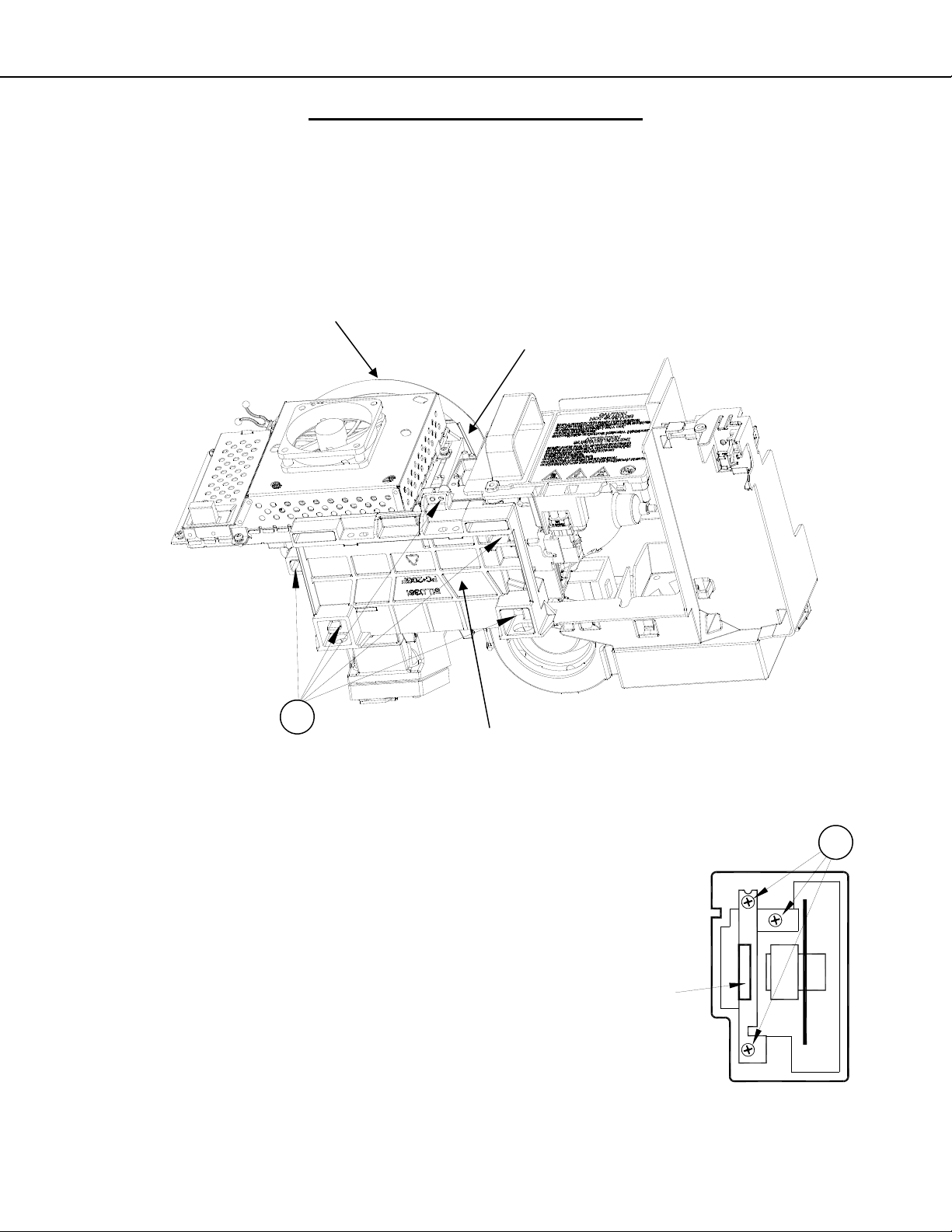
COLOR WHEEL REPLACEMENT
CAUTION: This procedure should be performed in a dust free environment.
Any dust entering into the optical compartment can cause abnormalities in the picture.
1. Remove the Optical Engine Assembly.
2. Remove the Lens Collar and cover the projection lens to protect it from scratches. See previous page.
3. Disconnect the 2 connectors, J6 & J7, from the front side of the Light Engine. Note the orientation of the
ribbon cable for re-assembly (Silver Contacts towards the Lens).
4. Access the optical compartment by removing screws (A) and the Engine Base from the bottom of the Optical Engine
Version 3.0
LENS COLLAR
A
J6 & J7
(Opposite Side of Formatter PWB)
ENGINE BASE
5. Remove the 3 screws (B) from the Color Wheel Assembly.
6. Use the metal Handle to lift the Color Wheel from the compartment.
7. For installation, reverse the procedure above.
CAUTION: Avoid touching or scratching the Color Wheel.
8. After re-assembly, perform the Index Delay Adjustment described in the
Service Adjustments section.
IMPORTANT: If part return is required, prevent damage by packing the
color wheel the same way the replacement part was sent to you.
Page 15
HANDLE
B
Page 16
MODELS: WD-73640 / WD-73740 / WD-73840 / WD-73C11 / WD-73CA1 /
WD-82740 / WD-82840 / WD-82CB1 / WD-92840
SCREEN REPLACEMENT 73” Models
Screen Assembly Removal and Replacement
1. V45C, V45, V45+ - Remove the Screw Caps to access screws (A).
2. V45++ - Remove the ORNAMENT LEFT & RIGHT first by pinching up and pulling away from the bottom.
Then remove the ORNAMENT CENTER using the same method.
3. Remove screws (A).
4. Remove screws (B) around the rear edge of the screen bezel.
5. During re-assembly replace screws in their original locations.
V45C,V45, V45+ (73”)
Version 3.0
V45++ (73”)
A A A
ORNAMENT
CENTER
(Speaker Cover)
A
B
Number and Location of
Screws Varies by Model
B
B
ORNAMENT RIGHT ORNAMENT LEFT
73 INCH
B
B
Page 16
Page 17
MODELS: WD-73640 / WD-73740 / WD-73840 / WD-73C11 / WD-73CA1 /
WD-82740 / WD-82840 / WD-82CB1 / WD-92840
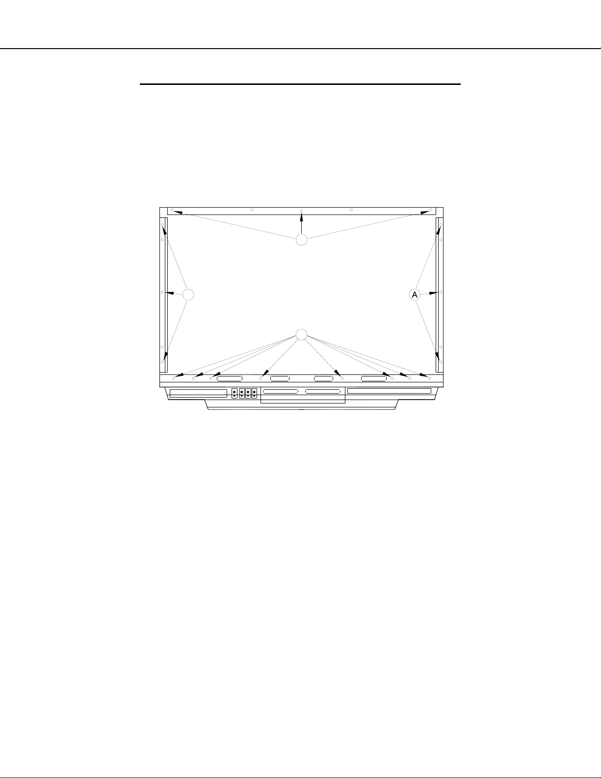
SCREEN REPLACEMENT 73” Models (continued)
Screen Removal From the Bezel-Front
1) Remove screws (A) and remove the top, bottom and side rails.
NOTE: The number and location of screws vary by model.
2) Lift the Fresnel Lens and Lenticular screen from the Bezel-Front.
3) During re-assembly replace screws in their original locations.
A
Version 3.0
A
Example Diagrams. The number and location of screws varies by model.
73 INCH
(Rear View)
A
Page 17
Page 18

MODELS: WD-73640 / WD-73740 / WD-73840 / WD-73C11 / WD-73CA1 /
WD-82740 / WD-82840 / WD-82CB1 / WD-92840
SCREEN REPLACEMENT 73” Models (continued)
CAUTION: Wear gloves when handling the Lenticular Screen and Fresnel Lens.
This prevents cuts and finger prints. Do not place Fresnel Lens in the sun.
This may cause fire and heat related injuries.
Lenticular Screen and Fresnel Lens Removal
1. After removing the top, bottom and side HOLDER-SCREEN rails and their cushions from the Bezel, lift the
screens as a single unit from the frame.
2. Separate the Lenticular Screen and Fresnel Lens.
Note: When separating the Lenticular Screen from the Fresnel Lens, use caution
while prying the Screen and Lens apart. Use a slot type screw driver, and
remove the pressure sensitive double sided tape.
Lenticular Screen and Fresnel Lens Replacement
1. Apply LENS-TAPE along the rear top edge of the Lenticular Screen.
2. Place the Fresnel Lens on top of the Lenticular Screen, and apply pressure along the top edge.
3. Place the screens in the screen frame and reinstall the cushions, top, bottom and side rails.
NOTE: The Lenticular Screen label must face the front and the Fresnel Lens label face the rear.
4. Reverse the Screen Removal Procedure and insert the screens in the Bezel.
Version 3.0
LENTICULAR
LENS
FRESNEL
SCREEN
LENS-TAPE
BEZEL FRONT
HOLDER-SCREEN-T
SPACER-SCREEN-T
COVER-HOLDER-T
LABEL
LABEL
HOLDER-SCREEN-B
SPACER-SCREEN-S
HOLDER-SCREEN-S
SPACER-SCREEN-B
Page 18
Page 19

MODELS: WD-73640 / WD-73740 / WD-73840 / WD-73C11 / WD-73CA1 /
WD-82740 / WD-82840 / WD-82CB1 / WD-92840
SCREEN REPLACEMENT 82” & 92” Models
Screen Assembly Removal
1. Remove screws (A) around the bottom rear edge.
2. (V45+) Remove the Pedestal cover and remove screws (B).
3. (V45++) Pull off ornamental Front Covers and Speaker Grill.
4. Remove the Speaker Box and Pedestal by removing screws (B).
5. Remove screws (C) from the bottom front of the screen assembly.
6. Remove screws (D) from the top rear edge of the cabinet.
NOTE: Leave one screw secured at the top. Then support the assembly to prevent it from falling while
removing the remaining screw.
V45+
WD-82740
WD-82CB1
Version 3.0
A A
V45++
WD-82840
WD-92840
B
PEDESTAL
D D D
SPEAKERBOX
B
A A
B
B
C
PEDESTAL
Page 19
Page 20

MODELS: WD-73640 / WD-73740 / WD-73840 / WD-73C11 / WD-73CA1 /
WD-82740 / WD-82840 / WD-82CB1 / WD-92840
SCREEN REPLACEMENT 82” & 92” Models (continued)
CAUTION: Wear gloves when handling the Lenticular Screen and Fresnel Lens.
This prevents cuts and finger prints. Do not place Fresnel Lens in the sun.
This may cause fire and heat related injuries.
Lenticular Screen and Fresnel Lens Removal
1. Remove four screws (A) in all four corners of the Screen Bezel.
2. Remove the Screen Bezel components from the Screen/Lens Assembly.
A X4
Version 3.0
CORNER-S-T
CORNER-CAP
TOP-L
HOLDER-SCREEN
S-L
CORNER
B-L
SCREEN/LENS
ASSEMBLY
FRONT
HOLDER-SCREEN-B
COVER-HOLDER-T
CORNER-S-T
CORNER-CAP
TOP-R
HOLDER-SCREEN
S-R
LABEL
CORNER
B-R
Page 20
Page 21

MODELS: WD-73640 / WD-73740 / WD-73840 / WD-73C11 / WD-73CA1 /
WD-82740 / WD-82840 / WD-82CB1 / WD-92840
SCREEN REPLACEMENT 82” & 92” Models (continued)
Lenticular Screen and Fresnel Lens Disassembly
1. Remove the HOLDER-SCREEN from the top, bottom and sides.
2. Separate the Lenticular Screen and Fresnel Lens.
HOLDER-SCREEN
Version 3.0
LENTICULAR
SCREEN
HOLDER-SCREEN
(TOP/BOTTOM)(SIDES)
FRESNEL
LENS
LENS
FRONT
Label Position
(Facing Outside)
Lenticular Screen and Fresnel Lens Replacement
1. Place the Fresnel Lens on top of the Lenticular Screen with the labels facing outside as shown.
2. Install the HOLDER-SCREEN, top, bottom and sides as shown above.
3. Reverse the disassembly procedure to reassemble and install the screen frame assembly.
NOTE: The Lenticular Screen must face the front and the Fresnel Lens must face the rear.
LENTICULAR
SCREEN
Page 21
Page 22

MODELS: WD-73640 / WD-73740 / WD-73840 / WD-73C11 / WD-73CA1 /
WD-82740 / WD-82840 / WD-82CB1 / WD-92840
MIRROR REPLACEMENT
MIRROR REPLACEMENT - 73” Models
1. To access the Mirror for replacement, remove the Screen Assembly (See Screen Assembly Removal).
2. The Mirror slides down into the Left, Right and Bottom Brackets inside the cabinet.
3. Then the Top Bracket is installed.
4. See the Mirror Parts section for instructions on preparing a replacement mirror.
TOP BRACKET
(73" Models)
SUPPORT
BRACKETS
Version 3.0
MIRROR REPLACEMENT - 82” & 92” Models
1. To access the Mirror for replacement, remove screws (A) and lift away the Mirror Cover(s). Note: 82” cover is
1 piece, 92” cover is 2 pieces.
2. The Mirror rests in place below the Mirror Cover.
3. See the Mirror Parts section for instructions on preparing a replacement mirror.
A
(2 Piece Cover)
A
92"
MIRROR
(Below Cover)
A
Page 22
Page 23

MODELS: WD-73640 / WD-73740 / WD-73840 / WD-73C11 / WD-73CA1 /
WD-82740 / WD-82840 / WD-82CB1 / WD-92840
SERVICE PROCEDURES
REMOTE CONTROL
NOTE: The Remote Controls differ between Type 1 and the Type 2 models.
TYPE 1
V45C V45 V45CA
WD-73C11 WD-73640 WD-73CA1
REMOTE CONTROL USE FOR SERVICE
Many service functions and adjustments are accessed using the Remote Control. The Type 1 remote does not have
buttons such as PLAY, FWD and RVW that are associated with operating connected devices. Service Proc edures are
described assuming a Type 1 remote is being used. However, if a Type 2 remote is being used, buttons can optionally
be substituted as follows:
TYPE 2
V45+ V45++ V45CB
WD-73740 WD-73840 WD-82CB1
WD-82740
WD-82840
WD-92840
Type 1
V45C / V45 / V45CA
V45+ / V45++ / V45CB
TYPE1 TYPE 2
<2> <2> or <PLAY>
Type 2
Version 3.0
<CH-UP> <CH-UP> or <FWD>
<CH-DOWN> <CH-DOWN> or <RVW>
Page 23
Page 24

MODELS: WD-73640 / WD-73740 / WD-73840 / WD-73C11 / WD-73CA1 /
WD-82740 / WD-82840 / WD-82CB1 / WD-92840
OPTION MENU
OPTION MENU
1. Press the <MENU> button on the remote control.
2. Press the buttons <2-4-7-0>. The screen will display the Option Menu.
Option Menu
<MENU><2-4-7-0>
Initialize
Power Restore OFF
Production Mode OFF
Digital Signal Strength <1~9>
NetCommand Software Vxx xxx.xx
Total hours of use 0
Version 3.0
SERVICE LEVEL INITIALIZATION
Service Level Initialization is used to restore all customer menu, video and audio settings to the original factory default
condition.
1. Enter the Option Menu <MENU><2-4-7-0>
2. Select “Initialize” and <ENTER>.
Option Menu
<MENU><2-4-7-0>
Initialize
Power Restore OFF
Production Mode OFF
Digital Signal Strength <1~9>
NetCommand Software Vxx xxx.xx
Total hours of use 0
Page 24
Page 25

MODELS: WD-73640 / WD-73740 / WD-73840 / WD-73C11 / WD-73CA1 /
WD-82740 / WD-82840 / WD-82CB1 / WD-92840
DIGITAL SIGNAL INFORMATION
Information on the currently selected digital channel can be displayed on screen.
1. Enter the Option / Service Menu <MENU><2-4-7-0>.
Option Menu
<MENU><2-4-7-0>
Initialize
Power Restore OFF
Production Mode OFF
Digital Signal Strength <1~9>
NetCommand Software Vxx xxx.xx
Total hours of use 0
1. Select “Digital Signal Strength” and <ENTER>.
Digital Signal Information
Version 3.0
“Digital Signal Strength” <ENTER>
Tuner
Frequency(MHz) 749
Signal Level <1~9>
Modulation 8VSB Air
Carrier Lock Locked
SNR 29.09
Correctable errors 0
Un Correctable errors 0
Page 25
Page 26

MODELS: WD-73640 / WD-73740 / WD-73840 / WD-73C11 / WD-73CA1 /
WD-82740 / WD-82840 / WD-82CB1 / WD-92840
RESET / INITIALIZATION
SERVICE TIP:
Many symptoms that are customer generated, intermittent or cannot be verified can be resolved by using the various
Reset and Initialization options. Before visiting the customer’s home ask the customer to 1st perform a System Reset. If
this does not resolve the issue, they can perform an A/V Reset. Then, if necessary, perform a user level Initialization.
The customer should be made aware when settings and/or options will be reset. For more information, see the chart
below.
Reset Name When to use How to use Resulting Action
Remote Control
Reset
TYPE 1 Only
Returns the remote control to normal
operation.
Press and hold the <POWER> button until it flashes twice
1)
then release the button.
Enter the code <0-0-0-0-0>. The <POWER> button will flash
2)
twice
The remote control is reset.
Version 3.0
Remote Control
TV Layer Reset
TYPE 2 Only
Remote Control
TV Volume/
Mute functions
A/V Memory
Reset, by individual input
A/V Reset, all
inputs
System Reset To reset the TV when it does not turn
Returns the remote control TV layer
to normal operation.
Returns the volume and mute functions of the remote control to TV volume and mute for TV, Cable/Sat,
VCR and DVD layers after the Audio
Lock for AV Receiver feature has
been used.
When the audio or video performance
or settings for a single input seem to
be incorrect.
When the audio or video performance
or settings for more than one input
seem to incorrect.
on or off, does not respond to the
remote control, front panel buttons or
has other unusual symptoms.
Select the remote control TV mode.
1)
Press and hold the <POWER> button until it flashes twice
2)
then release the button.
Enter the code <0-0-9-3-5>. The <POWER> button will flash
3)
twice
Select the remote control TV mode.
1)
Press and hold the <POWER> button until it flashes twice
2)
then release the button.
Enter the code <9-9-3>< VOL >. The <POWER> button
3)
will flash four times.
<MENU> “Audio/Video” “AV Reset” <ENTER> All Audio and Video settings
While viewing the TV, press the front panel buttons <INPUT> +
<VOL > at the same time and hold for 10 sec.
Press the <POWER> button on the front panel and hold it for 8
seconds.
The remote control TV layer
is reset.
The remote will now operate
the TV's volume and mute
when the slide switch is in
the TV, CABLE/SAT, VCR
or DVD positions.
for the individual input are
reset except for the Listen
To, Language, Balance and
Closed Caption settings.
All Audio and Video settings
are reset to the factory default settings. No other
menu options are changed.
TV Micro Re-boots. Note:
The changes made during
the current TV-On period
may be lost. All other previous user settings are not
lost.
Initialize User
Level
Initialize - Service Level
V-Chip Password Bypass
Unlock Front
Panel
To reset all customer settings except
V-Chip
To reset all customer settings <MENU><2-4-7-0> "INITIALIZE" <ENTER> All customer menu options
If V-Chip password is not known Press <LAST>+<9> at the same time. Password will be bypassed.
To unlock the front panel if it has
been locked in the V-Chip Menu.
Press <MENU><1-2-3><ENTER> All customer menu options
Press and hold the front panel <INPUT>
button for 10 seconds.
and A/V settings except VChip & locked ISF are reset
to factory default.
and A/V settings are reset
to factory default.
If in the V-Chip menu, enter
a new password.
Front Pan
erational. Other V-Chip
settings not changed. Note:
Cannot be performed while
in the Low Power mode and
the set is Off.
e
l becomes op-
Page 26
Page 27

MODELS: WD-73640 / WD-73740 / WD-73840 / WD-73C11 / WD-73CA1 /
WD-82740 / WD-82840 / WD-82CB1 / WD-92840
LED INDICATI ONS AND SELF DIAGNOSTICS
The front panel Status LED provides an indication of the set’s operation and the possible cause of a malfunction.
NORMAL INDICATIONS
STATUS LED Indication Condition
Off Off (Standby)
Green Power On
Slow Blinking Green Power Off with Timer Set. Power On normally
Fast Blink Green 80 seconds after Power Off Power Off Lamp cooling. Wait for blinking to
stop to Power On.
Version 3.0
Fast Blinking Green 1 to 3 minutes after Power
Restored from AC interrupt, Power On, System
Reset or Software update.
ABNORMAL INDICATIONS
STATUS LED Indication Condition
Steady Red Lamp Failure (See Error Code 66)
Steady Yellow DMD Temperature Excessive
Blinking Yellow Lamp Cover Open (See Error Code 32)
Blinking Red then Blinking Yellow Circuit Failure (See Self Diagnostics)
Boot-up. Wait for blinking to stop to Power On.
SELF DIAGNOSTICS
A blinking red and yellow Status LED will indicate an Error Code that can help determine the cause of a circuit
failure.
The number of Red blinks indicates the value of the MSD (tens digit) of the Error Code.
The number of Yellow blinks indicates the value of the LSD (ones digit) of the Error Code.
Example: If the Error Code is “37”, the LED will continuously blink Red three times, followed by blinking Yellow
seven times.
See the following page for a list of Error Codes.
To perform a System Reset, press and hold the Power button for 10 seconds. Or, unplug the set for 10 seconds
then restore power.
Number of Red Blinks Number of Yellow Blinks
3 7
Error Code: 37
Page 27
Page 28

MODELS: WD-73640 / WD-73740 / WD-73840 / WD-73C11 / WD-73CA1 /
WD-82740 / WD-82840 / WD-82CB1 / WD-92840
ERROR CODES
Error Codes, descriptions and the most likely cause of failure are listed below:
ERROR CODES
Code Description Most Likely Cause
Loss of 12V from PWB-POWER to Engine /
17 I2C Communication loss between TV Micro and Engine
Engine will not accept data
18
(ASIC-READY signal from Engine is not detected)
Lamp Cover is open.
32*
Lamp turns Off while the TV is playing.
34**
Lamp Failure
Lamp Enable signal from engine is lost.
36 Exhaust Fan rotation not detected Check Exhaust Fan / Check J4 circuitry
37 Engine (DMD) fan rotation not detected Check DMD Fan / Check J5 circuitry
42 Sirocco fan (Lamp fan) rotation not detected Check Sirocco Fan / Check J8 circuitry
44 LVDS cable between PWB-MAIN and Engine not detected Check LVDS Cable & circuitry
48 PON-SHORT 3.3V or 5V switched supply short PWB-MAIN Failure
57 Ballast communication problem (ballast to chassis)
16 LAMP-EN Detection
Lamp did not turn on at P-ON sequence
66**
(No Lamp inserted)
(Disconnected cable between ballast and lamp)
(Lamp-Enable goes to PWB-MAIN but not to Ballast)
Check PE & PE2 circuitry
Engine Failure, PWB-MAIN Failure
LDVS circuitry
Engine Failure
Check CD connector
Lamp Cartridge Failure
Loss of 340V from PWB-POWER to Ballast /
Check PL & CJ1 circuitry
Loss of communications between PWB-MAIN
and Ballast / Check FB & CJ3 circuitry
Ballast Failure
Check Color Wheel / Check J6 & J7 circuitry /
Engine Failure
Check CJ4 circuitry
No Lamp Inserted.
HV connection or lead wire to lamp.
Lamp Cartridge Failure
Version 3.0
* Error Code 32 is indicated by a flashing Yellow Status LED. The code is stored in the Error code Log. See below.
** Error Codes 34 & 66 are indicated by a steady Red Status LED. The code is stored in the Error code Log. See
below.
ERROR CODE LOG
The Error Code Log can be used to retrieve the code for an error that occurred in the past.
To access the Error Code Log: Press <MENU> <3-5-6-4>
Error Code Log Definitions
PAGE - Current page number
CURRENT TIME - total hours of operational
use.
USAGE TIME - usage hours when the error
occurred.
CODE - the specific Error Code that oc-
curred.
STATUS: HAPPENED - Indicates an error
was recorded.
Press <CANCEL> to erase the Log.
NOTE: The Error Code Log is intended as a ref-
erence tool and is not meant to be used as a final
Error Code Log
<MENU><3-5-6-4>
***** PAGE (001/001) *****
CURRENT TIME: 01455 HOURS
USAGE TIME CODE STATUS
00413 HRS 44 HAPPENED
00716 HRS 57 HAPPENED Press Up to Previous Page
Press Down to Next Page
Press Right to Top Page
Press Left to Last Page
Press CANCEL to Erase
determination of a defective part.
Press MENU to Exit
Page 28
Page 29

MODELS: WD-73640 / WD-73740 / WD-73840 / WD-73C11 / WD-73CA1 /
WD-82740 / WD-82840 / WD-82CB1 / WD-92840
SPEAKER TRANSDUCER AND SPEAKER FREQUENCY TEST (V45++ Only)
These procedures will test the TV’s speakers using an internal tone generator.
1. Press the <MENU> button on the remote control. The Customer Menu will appear.
2. Press the <2-4-5-7> buttons. The Service Menu will appear.
3. Press the <0> button. The Data Transfer & Geometry Menu will appear. See below.
Note: Before activating the SPEAKER TEST, be sure that the SOUND is not in STEREO mode.
Use SURROUND, MUSIC or NIGHT m ode.
4. Use the <> buttons to select “SPEAKER TEST” and press <ENTER>. The Speaker Test Transducer
Test Menu will be displayed. A tone will automatically cycle from one speaker to the next as indicated on
screen. Follow the instructions to manually cycle the tone.
5. From the Data Transfer & Geometry Menu, use the <> buttons to “SPEAKER FREQUENCY TEST.”
The Speaker Frequency Test Menu will be displayed. A tone will automatically cycle from one frequency
to the next as indicated on screen. Follow the instructions to manually cycle the frequency tone.
Data Transfer & Geometry Menu <MENU><2-4-5-7><0>
RESTORE ENGINE DATA FROM BACKUP
RESTORE GEOMETRY DATA FROM BACKUP
MANUAL GEOMETRY ALIGNMENT
RESTORE INDEX DELAY
SAVE ENGINE AND GEOMETRY SETTING TO BACKUP
SPEAKER TEST
SPEAKER FREQUENCY TEST
BACKUP AND RESTORE ISF SETTINGS
RED ONLY AND GREEN ONLY
Version 3.0
Page 29
Page 30

MODELS: WD-73640 / WD-73740 / WD-73840 / WD-73C11 / WD-73CA1 /
WD-82740 / WD-82840 / WD-82CB1 / WD-92840
SERVICE ADJUSTMENTS
Service Adjustments include Adjustment Procedures and Data Transfer Functions.
Electrical Adjustments (there are no mechanical adjustments)
• Horizontal and Vertical Centering Adjustment
• Index Delay Adjustment
• Geometry Alignment
• Data Transfer Functions
Test Equipment and Test Patterns
• Remote Control
• Internally generated Test Patterns
• No external test equipment or pattern generators are required.
SERVICE MENU
The Service Menu is used for all service adjustments.
Service adjustments can only be performed using the remote control.
1. Activating the Service Menu
1. Press the <MENU> button on a remote control. (The Customer Menu will appear.)
2. Press the buttons <2-4-5-7>. (The Service Menu will appear.)
2. Test Pattern Activation
When in the Service Menu, press the <2> or <> key on the remote to activate the internal test patterns (no
indication will be displayed initially). Use <CH-UP/CH-DOWN> or <
<2> or <> a second time and use <CHAN-UP/CHAN-DOWN> or <
Press <2> or <> again to toggle back to the previous patterns.
3. Adjustment Overview—Specific adjustment procedures follow.
1. When in the Service Menu use the <VIDEO> button to toggle to adjustment desired indicated by the
number and abbreviation displayed on screen.
2. For Geometry, from the Service Menu press <0> and select “Manual Geometry Alignment” <ENTER>.
4. Adjusting Data
After selecting an adjustment item, use the Navigation arrows or other buttons indicated in the adjustment
procedure to perform the adjustment.
5. Saving Data
Press <ENTER> to save the adjustment data. The menu display will turn red for approximately one second.
Note: If the circuit adjustment mode is terminated without pressing <ENTER>, changes in adjustment data
are not saved.
6. Exiting the Service Menu
Press <EXIT> to quit.
Service Menu
<MENU> <2-4-5-7>
SERVICE
TVM
1. HVPOS
4
-3
/> to toggle between patterns. Press
/> to access additional patterns.
Version 3.0
Page 30
Page 31

MODELS: WD-73640 / WD-73740 / WD-73840 / WD-73C11 / WD-73CA1 /
WD-82740 / WD-82840 / WD-82CB1 / WD-92840
ADJUSTMENT PROCEDURES
Horizontal and Vertical Position Adjustment
1. Enter the Service Menu <MENU><2-4-5-7>.
2. Select the Geomet ry Test Pattern shown <2> <CH-DOWN>or <
3. If necessa ry, use the <VIDEO> button to select the adjustment, “1.HVPOS”.
4. After selecting the HVPOS adjustm ent item, use the Navigation <> buttons to center the display.
5. Press <ENTER> to save the adjustment data. The on-screen display will flash red whil e the data is saved.
Vertical & Horizontal Position Adjustment
<MENU><2-4-5-7> <2> <CH-DOWN> or <
Adjustment
SERVICE
TVM
1.HVPOS
-3
4
> x2.
> x2
Data (HPOS)
Data (VPOS)
Version 3.0
Index Delay Adjustment (Perform after color wheel replacement)
1. Enter the Service Menu <MENU><2-4-5-7>.
2. Select the Ramp Pattern shown below <2> <CH-DOWN> or <
3. Use the <VIDEO> button to select the adjustment, “60.IDL”.
4. After selecting the IDL adjustment item, use the Navigation <> buttons to adjust the ramp pattern color
bars for the smoothest transition from dark to bright.
5. Press <ENTER> to save the adjustment data. The on-screen display will turn red while the data is saved.
Index Delay Adjustment
<MENU><2-4-5-7> <2> <CH-DOWN> or <
Adjustment
SERVICE
TVM
60.IDL
201
> x3.
> x3 <VIDEO>
Data
Page 31
Page 32

MODELS: WD-73640 / WD-73740 / WD-73840 / WD-73C11 / WD-73CA1 /
WD-82740 / WD-82840 / WD-82CB1 / WD-92840
Manual Geometry Alignment
1. Entering the Manual Geometry Alignment Mode
1. Activate the Service Mode <MENU><2-4-5-7>.
2. From the Service Menu, press the <0> button. The Data Transfer & Geometry Menu will appear.
3. Use the <> buttons to select “MANUAL GEOMETRY ALIGNMENT” <ENTER>. The Manual Geometry
Alignment Pattern will appear.
Type 2 Data Transfer & Geometry Menu <MENU><2-4-5-7><0>
RESTORE ENGINE DATA FROM BACKUP
RESTORE GEOMETRY DATA FROM BACKUP
MANUAL GEOMETRY ALIGNMENT
RESTORE INDEX DELAY
SAVE ENGINE AND GEOMETRY SETTING TO BACKUP
BACKUP AND RESTORE ISF SETTINGS
RED ONLY AND GREEN ONLY
Manual Geometry Alignment
Version 3.0
<MENU><2-4-5-7><0> “MANUAL GEOMETRY ALIGNMENT”<ENTER>
Page 32
Page 33

MODELS: WD-73640 / WD-73740 / WD-73840 / WD-73C11 / WD-73CA1 /
C
r
WD-82740 / WD-82840 / WD-82CB1 / WD-92840
2. Manual Geometry Alignment
Note: Upon entering the Manual Geometry Alignment Mode the first time, the geometry may appear distorted
because all factory geometry correction is automatically disabled. Press <EXIT> to quit and re-enable
the factory geometry correction. Pressing <1> <ENTER> and <EXIT> will cause the TV to operate with
out factory geometry correction (distortion will be present).
Note: At any time the original factory geometry data can be restored from backup:
From the Data Transfer & Geometry Menu <MENU><2-4-5-7><0>, select “RESTORE
GEOMETRY DATA FROM BACKUP” <ENTER>.
+
urso
+
Adjustment Points
(16 Total)
Version 3.0
Align Cursor + Flush With Bezel Edge
Phase 1 - 16 Point Geometry Alignment
1. 16 Adjustment Points are indicated by white dots around the edge of the raster. The adjustment position is
indicated by a + cursor.
2. Starting from the upper left corner, use the <> buttons to align the + at each point in a straight line,
flush with the bezel as a reference. See example above.
Note: Only the cursor will move. The Geometry Pattern will not change.
3. After adjusting each point, use the <CH-UP> or <
and repeat until all 16 points have been adjusted.
4. After all 16 points are adjusted and the cursor is returned to the original starting point, press <ENTER> then
<EXIT>. Correction will be automatically calculated and saved and the Manual Geometry Alignment will be
terminated.
5. Re-activate the Manual Geometry Alignment. The geometry pattern will appear with the corrections applied. If
Geometry is acceptable, press <EXIT> to quit. To touchup the raster geometry, proceed to Phase 2.
Phase 2 - Geometry Touch-up Alignment
1. If additional correction is necessary after performing the Manual Geometry Alignment, re-enter the Manual
Geometry Alignment mode.
2. Use the <CH-UP/CH-DOWN> or <
3. Use the <> buttons to indicate the direction and amo unt of correction necessary at the particular
point. Note: Only the cursor will move. The Geometry Pattern will not change.
4. Press the <INFO> button to apply the correction. The Geometry Pattern will now show the correction.
5. Repeat steps 2, 3 and 4 as needed.
6. Press <ENTER> then <EXIT> to save your changes. The Manual Geometry Alignment will be terminated.
7. To proceed to Phase 3, re-activate the Manual Geometry Alignment.
/> buttons to shift the cursor to the point needing correction.
> button to shift the cursor to the next point clockwise
Page 33
Page 34

MODELS: WD-73640 / WD-73740 / WD-73840 / WD-73C11 / WD-73CA1 /
WD-82740 / WD-82840 / WD-82CB1 / WD-92840
Phase 3 - 4:3 and 16:9 Alignment
1. With the Manual Geometry Alignment activated, press <VIDEO> to enter the 4:3 Alignment Mode. The pattern below will be displayed.
Note: Pressing <VIDEO> will toggle between the 4:3,16:9 (top, top-ce nter, center & bottom) and 16 Point Ge-
ometry Alignment modes.
2. In the 4:3 Alignment Mode, pressing <CH-UP/CH-DOWN> or <
/> will cause the geometry pattern to be
displayed with 11 preset amounts of correction. Toggle through them until you find the one with the straightest Blue 4:3 Lines. It may help to count the patterns as you cycle through them. When you find the pattern
with the straightest Blue 4:3 Lines, press <VIDEO>. The Top 16:9 Alignment Mode will then be activated as
indicated by the Top Red 16:9 Line displayed in the pattern.
4:3 MODE
Version 3.0
Select Straightest Blue Lines
3. In the 16:9 Alignment Mode, pressing <CH-UP/CH-DOWN> or </> will cause the geometry pattern to be
displayed with 15 different preset amounts of correction to the Red Line. Toggle through them until you find
the one with the straightest Red Line. Again, count the patterns as you cycle through them. When you find
the pattern with the straightest line, press <VIDEO>. The Top-Center Red Line will be displayed in the pattern.
4:3 MODE
Select Straightest Red Line (Top)
Page 34
Page 35

MODELS: WD-73640 / WD-73740 / WD-73840 / WD-73C11 / WD-73CA1 /
WD-82740 / WD-82840 / WD-82CB1 / WD-92840
4. Repeat the process of pressing <CH-UP/CH-DOWN> or </> to display the 15 different preset amounts
of correction to the Top-Center Red Line. When you find the pattern with the straightest line, press
<VIDEO> to proceed to the Center Red Line. Repeat the process for the Center Line, followed by the Bottom Line. Press <ENTER> then <EXIT> to exit and save the 4:3 and 16:9 data.
5. Select the Geometry Test Pattern (See HVPOS). If Geometry is acceptable, press <EXIT> to quit.
Version 3.0
Select Straightest Red Line (Top- Center)
Select Straightest Red Li ne (Center)
4:3 MODE
Select Straightest Red Line (Bottom)
Page 35
Page 36

MODELS: WD-73640 / WD-73740 / WD-73840 / WD-73C11 / WD-73CA1 /
WD-82740 / WD-82840 / WD-82CB1 / WD-92840
DATA TRANSFER FUNCTIONS
Data Transfer
Service Data is duplicated and stored in separate EEPROMs in two locations.
PWB-MAIN - Working Service Data for TV operation
OPTICAL ENGINE - Backup Service Data
The Optical Engine also includes data for the Index Delay setting for color wheel timing determined at the factory.
The PWB-MAIN also includes User and/or ISF settings. The User/ISF data is not backed up on the Engine. However if
used, it can be backed up onto a USB flash drive.
Data Transfer Procedures should be followed…
After PWB-MAIN Replacement:
1. Restore Engine Data From Backup.
2. Restore Geometry Data From Backup.
3. Restore ISF Settings From Flash Drive. (Only if backup USB flash drive is available).
After OPTICAL ENGINE Replacement:
1. Restore Index Delay.
Version 3.0
Data Transfer Procedure:
1. Enter the Service Mode <MENU><2-4-5-7> Select the Data Transfer & Geometry Menu <0>
Note: Besides MANUAL GEOMETRY ALIGNMENT, six data transfer choices are listed on screen.
RESTORE ENGINE DATA FROM BACKUP - copies backup factory adjustments HVPOS, White Balance
RESTORE GEOMETRY DATA FROM BACKUP - copies backup factory Geometry Alignment data from
RESTORE INDEX DELAY - copies factory Index Delay Adjustment data from the Optical Engine to the
SAVE ENGINE AND GEOMETRY SETTING TO BACKUP - copies all working data from the PWB-MAIN
BACKUP AND RESTORE ISF SETTINGS - allows the ISF (ADV) video settings to be backed up and
RED ONLY AND GREEN ONLY - displays the video in red or green only during ISF Calibration.
2. Use the <> buttons to select the item and press <ENTER>.
3. Follow on-screen instructions if given.
4. Press <EXIT> to quit.
Data Transfer & Geometry Menu <MENU><2-4-5-7><0>
RESTORE ENGINE DATA FROM BACKUP
RESTORE GEOMETRY DATA FROM BACKUP
MANUAL GEOMETRY ALIGNMENT
RESTORE INDEX DELAY
SAVE ENGINE AND GEOMETRY SETTING TO BACKUP
BACKUP AND RESTORE ISF SETTINGS
RED ONLY AND GREEN ONLY
Warning: Only use “SAVE ENGINE AND GEOMETRY SETTING TO BACKUP”
and Index Delay from the Optical Engine to the PWB-MAIN.
the Optical Engine to the PWB-MAIN.
PWB-MAIN.
into backup memory on the Optical Engine.
restored using an external USB flash drive.
Page 36
Page 37

MODELS: WD-73640 / WD-73740 / WD-73840 / WD-73C11 / WD-73CA1 /
WD-82740 / WD-82840 / WD-82CB1 / WD-92840
Using Lead Free Solder
Pb Solder
The symbol shown above indicates Lead (Pb) Free Solder was used during the construction of PWBs. Only Lead Free
Solder should be used when servicing these PWBs.
Solder must be compatible with that used by the manufacturer. Leaded solder can not be used on PWBs manufactured
with Pb-free solder. The Mitsubishi standard for service requires the use of Tin-Silver-Copper (Sn-96.5, Ag-3.0, Cu-0.5).
It can be obtained through the Parts Department.
Order part number: PB FREE SOLDER
Lead Free Solder has a higher melting point, and does not “wet” as well as leaded solder. This means it does not adhere as readily to the solder iron tip and the surface to be soldered. To counteract this, the flux used is more corrosive.
The following cautions must be taken when using Pb Free Solder.
Higher temperatures can cause the PWB to warp, detaching surface mount components.
Higher temperatures may cause thermal damage to components.
Higher temperatures can cause plastics such as connectors, relays, LEDs, electrolytic capacitors to melt or warp.
Higher temperatures can cause surface oxidation resulting in poor solder spread-ability and wet-ability.
The flux is more corrosive.
The time required for a good solder connection may take longer.
Poor wet-ability can cause solder balls.
Higher temperatures can cause flux spattering.
Soldering iron tip life is shortened.
Dull finish solder joints (not shiny) can appear to be a “cold” solder joint.
In general a tip temperature of 700° F will usually provide good results.
Displays used to indicate Pb-free
PWBs will be marked, indicating the level of Pb-free construction. Table 1 defines the levels by phase and shows the
different symbols that will be displayed on the PWB. Additionally, a PWB constructed using Pb-free solder may be simply
marked LFS.
When possible, the indication will be placed close to the part number that is screened onto the PCB (not the part label).
Version 3.0
Pb-Free
Phase Definition Display
Phase-1 PCB's constructed using
Pb-free solder.
Pb Solder
Phase-2 Solder, PCB surface
Phase-3 Solder, PCB surface
finishing and component
lead plating is Pb-free.
Components may have
internal Pb.
finishing and components
are Pb-free. (100% Pbfree)
Table 1: Pb-Free Phases and Symbols
Pb Joints
Pb PCA
Page 37
Short Display (When the
area is too small)
Pb S
Pb J
Pb P
Page 38

MODELS: WD-73640 / WD-73740 / WD-73840 / WD-73C11 / WD-73CA1 /
WD-82740 / WD-82840 / WD-82CB1 / WD-92840
Chip Parts Replacement
Some resistors, shorting jumpers (0 Ohm resistors), ceramic capacitors, transistors and diodes are chip parts. The following precautions should be taken when replacing these part s.
Cautions:
1. Use a fine tipped, well insulated soldering iron and tweezers.
2. Melt the solder and remove the chip parts carefully so as not to tear the copper foil from the printed circuit
board.
3. Discard removed chips; do not reuse them.
4. Do not apply heat for more than 3 (three) seconds to new chip parts.
5. Avoid using a rubbing stroke when soldering
6. Take care not to scratch, or damage the chip parts when soldering.
7. Supplementary cementing is not required.
Chip Parts Removal (Resistors, Capacitors, etc.)
1. Grasp the part with tweezers.
2. Melt the solder at both sides alternately, and remove one side of the part with a twisting motion.
3. Melt the solder at the other side and remove the part.
Chip Parts Removal (Transistors)
1. Melt the solder of one lead and lift the side of that lead upward.
2. Simultaneously melt the solder of the other two leads and lift the part from the PCB.
Replacement
1. Pre-solder the contact points on the circuit pattern.
2. Press the part downward with tweezers and apply the soldering iron as shown.
Version 3.0
Page 38
Page 39

MODELS: WD-73640 / WD-73740 / WD-73840 / WD-73C11 / WD-73CA1 /
WD-82740 / WD-82840 / WD-82CB1 / WD-92840
REPLACEMENT PARTS
Safety Critical Parts Designation
Safety Critical Components are indicated in the Parts List by Bold Type and a
They are indicated in the schem atic diagrams by a red hatch and a
The replacement for any safety critical part should be identical in value and characteristics.
Fuse Replacement Warning
Caution: For continued protection against risk of fire, replace only with the same type fuse. See parts list.
PWB-POWER
V45C, V45, V45CA, V45+, V45CB
F9000
F9004
F9003
125V 10A
125V 5A
125V 5A
Symbol.
symbol.
Version 3.0
F9A01
24V 6.3A
F9003
F9005
F9000
V45++
125V 5A
125V 10A
125V 10A
F9001
125V 5A
PWB-MAIN
Page 39
Page 40

MODELS: WD-73640 / WD-73740 / WD-73840 / WD-73C11 / WD-73CA1 /
WD-82740 / WD-82840 / WD-82CB1 / WD-92840
[ # ] Model Legend: (a) WD-73640, (b) WD-73740, (c) WD-73840, (d) WD-73C11, (e) WD-7 3CA1, (f) WD-82740,
(g) WD-82840, (h) WD-82CB1, (i) WD-92840
Safety Critical Part - Use exact replacement only
Parts Quick Reference
Description Part Number #
PWB-MAIN 934C407001 ad
PWB-MAIN 934C407002 bf
PWB-MAIN 934C407003 cgi
PWB-MAIN 934C407016
PWB-MAIN 934C407017
PWB-POWER 934C409001 ade
PWB-POWER 934C409002 bfh
PWB-POWER 934C409003 cgi
PWB-SOUND 934C408001 cgi
PWB-CONTROL 934D162001 abdefh
PWB-CONTROL 934D162002 cgi
PWB-PREAMP 934D163001 ade
PWB-PREAMP 934D163002 bcfghi
PWB-SW-LAMP 934D164001
PWB-AUX 934D165001 cgi
BLUETOOTH-MODULE 938P213010 cgi
OPTICAL-ENGINE 938P197040
OPTICAL-ENGINE 938P197060 fgh
OPTICAL-ENGINE 938P197070 i
ASSY-PWB-BALLAST 938P198010
LAMP-CARTRIDGE 915B455011
COLOR-WHEEL 938P215010
PROJECTION-LENS 491P245010
FAN-SCIROCCO 299P321020
EXHAUST-FAN 299P356010
DMD-FAN 299P382010
REMOTE-CONTROL 290P187010 ade
REMOTE-CONTROL 290P187040 bcfghi
SCREEN-LENTICULAR 491P243030 abcde
SCREEN-LENTICULAR 491P243040 fh
SCREEN-LENTICULAR 491P231020 g
SCREEN-LENTICULAR 491P247010 i
LENS-FRESNEL 491P242060 abcde
LENS-FRESNEL 491P232010 fgh
LENS-FRESNEL 491P248010 i
MIRROR 73” KIT-MIR V45 73 abcde
MIRROR 82” KIT-MIR V45 82 fgh
MIRROR 92” KIT-MIR V45 92 i
e
h
abcde
Version 3.0
Page 40
Page 41

MODELS: WD-73640 / WD-73740 / WD-73840 / WD-73C11 / WD-73CA1 /
WD-82740 / WD-82840 / WD-82CB1 / WD-92840
[#] Model Legend: (a) WD-73640, (b) WD-73740, (c) WD-73840, (d) WD-73C11, (e) WD-73CA1, (f) WD-82740, (g) WD-82840, (h) WD-82CB1, (i) WD-92840
[] Safety Critical Part - Use exact replacement only
Ref # Part # Part Name & Description
INTEGRATED CIRCUITS
IC1B01 271P349010 IC - MIC2005-0.5YM6
IC1B05 271P349010 IC - MIC2005-0.5YM6 cgi
IC1B06 276P578020 IC-C-MOS - MM3376A33NRE cgi
IC1F01 276P963010 IC-C-MOS - Si2153-A40-GM
IC2A01 276P726020 IC-C-MOS - 276P726
IC3A00 271P348010 IC - YDA164 abdefh
IC3F01 276P515010 IC-C-MOS - DIR9001PWR cgi
IC3G01 276P513010 IC-C-MOS - D708E001BRFP266 cgi
IC3H01 276P907010 IC-C-MOS - W9864G6JH-6 cgi
IC3J01 271P326020 IC - NJM2831F05 cgi
IC3J02 271P355010 IC - NJM2781V cgi
IC3J03 271P345010 IC - NJM2753V cgi
IC3J04 276P503010 IC-C-MOS - AK5358AETP cgi
IC3L01 276P828010 IC-C-MOS - PCM1681PWPR cgi
IC3L02 276P828010 IC-C-MOS - PCM1681PWPR cgi
IC3L03 276P741010 IC-C-MOS - AK4420ETP cgi
IC3L05 276P741010 IC-C-MOS - AK4420ETP cgi
IC3M01 276P930010 IC-C-MOS - LM48410SQ cgi
IC3M02 276P930010 IC-C-MOS - LM48410SQ cgi
IC3M03 276P930010 IC-C-MOS - LM48410SQ cgi
IC3M04 276P930010 IC-C-MOS - LM48410SQ cgi
IC3N01 276P930010 IC-C-MOS - LM48410SQ cgi
IC3N02 276P930010 IC-C-MOS - LM48410SQ cgi
IC3N03 276P930010 IC-C-MOS - LM48410SQ cgi
IC3N04 276P930010 IC-C-MOS - LM48410SQ cgi
IC3P01 271P254010 IC - ISL6545ACBZ-TS2698 cgi
IC4A01 276P742020 IC-C-MOS - PST8428NR
IC4A02 276P687030
IC4F01 276P744010 IC-C-MOS - NT5TU64M16DG-AC
IC4F02 271P033020 IC - LP2996LQNOPB
IC4F03 276P744010 IC-C-MOS - NT5TU64M16DG-AC
IC4G01 271P251040 IC - MM1662FHBE
IC4J01 276P950020 IC-C-MOS - TC58NVG0S3ETA00
IC7A01 276P576010
IC7D01 276P962010
IC9010 267P324010 HIC - STR-W6754
IC9020 271P142010 IC - RT9H301C
IC9030 271P315010 HIC - ST R-A6159
IC9031 271P142010 IC - RT9H301C
IC9A01 271P381010 IC - IR3842AMTRPbF
IC9A02 270P950020 IC - NJM78M05DL1A - TE1
IC9A03 271P379010 IC - TPS54326PWPR
IC9A04 271P379010 IC - TPS54326PWPR
IC9A05 271P380010 IC - TPS54426PWPR
IC9A07 271P321010 IC - PST8242NR
IC9A08 276P578020 IC-C-MOS - MM3376A33NRE
IC9A09 270P950010 IC - NJM78M09DL1A(TE1) bcfghi
IC9G80 271P349010 IC - MIC2005-0.5YM6
CHIP Type Transistors (Listed by Part No.)
261P842080 2SC3052-T112-1E;F
Q9012 261P227010 TR - FQPF27P06 bcfghi
261P844010 RT1N436C-T112-1
261P845010 RT1P241C-T1112-1
261P874010 FDS8896 cgi
261P875010 FDS8984
261P876010 FDS6298 cgi
261P877010 FDC655BN
261P878010 RT3Y97M-T111-1 cgi
261P937010 2SC3440-T112-F bcfghi
IC-C-MOS - BCM3549SLKFSB5G(B2)
IC-C-MOS - UPD78F1178GF(S)-GAT-AX
IC-C-MOS - uPD78F9500MA(S)-CAC-E2-A
TRANSISTORS
TRANSISTORS
Conventional Transistors (By Ref #)
[#]
bcfghi
Ref # Part # Part Name & Description
DIODES
D2A11 262P904070 DIODE-CHIP - DZ2J051M0L
D2A12 262P830010 D-CHIP - MC2850-T111-1
D2A13 262P830010 D-CHIP - MC2850-T111-1
D2A21 262P904070 DIODE-CHIP - DZ2J051M0L
D2A22 262P830010 D-CHIP - MC2850-T111-1
D2A23 262P830010 D-CHIP - MC2850-T111-1
D2A31 262P904070 DIODE-CHIP - DZ2J051M0L
D2A32 262P830010 D-CHIP - MC2850-T111-1
D2A33 262P830010 D-CHIP - MC2850-T111-1
D2A41 262P904070 DIODE-CHIP - DZ2J051M0L cgi
D2A42 262P830010 D-CHIP - MC2850-T111-1 cgi
D2A43 262P830010 D-CHIP - MC2850-T111-1 cgi
D4A05 262P830010 D-CHIP - MC2850-T111-1
D4A06 262P830010 D-CHIP - MC2850-T111-1
D7A04 262P828020 D-CHIP - MC2836-T112-1
D7E00 262P830010 D-CHIP - MC2850-T111-1 cgi
D8000 264P584020 DIODE-LE - SML1216W-C,D
D8305 262P230020 DIODE-LE - SID1G307C bcfghi
D8306 262P230020 DIODE-LE - SID1G307C bcfghi
D8307 262P230020 DIODE-LE - SID1G307C bcfghi
D9005 262P170010 DIODE - SARS01
D9006 262P203070 DIODE - UF4007
D9009 262P201060 DIODE - 1N4006
D9010 262P201060 DIODE - 1N4006
D9013 262P084010 DIODE - 31DQ06
D9014 264P774020 DIODE - MTZJ4.7A,B,CQLF
D9015 262P085010 DIODE - 11EFS2N-TA2B5
D9018 264P045080 DIODE - 1S2076A/1S2471OM
D9019 264P045080 DIODE - 1S2076A/1S2471OM
D9020 264P045080 DIODE - 1S2076A/1S2471OM
D9022 264P775080 DIODE - MTZJ6.2CQLF
D9023 262P085010 DIODE - 11EFS2N-TA2B5
D9024 262P085010 DIODE - 11EFS2N-TA2B5
D9026 262P208010 DIODE - FCHS10A12-15A
D9207 262P200010 DIODE - D6SB80-7001
D9A03 262P828010 D-CHIP - MC2838-T112-1
D9A04 262P900020 DIODE - FLZ5V6C T&R 2500/reel
D9A05 262P809010 D-CHIP - M1FS4-5063
D9A06 262P900010 DIODE - FLZ3V9A T&R 2500/reel
D9A08 262P900010 DIODE - FLZ3V9A T&R 2500/reel
D9A09 262P900010 DIODE - FLZ3V9A T&R 2500/reel
D9A12 262P828010 D-CHIP - MC2838-T112-1
D9A15 262P828010 D-CHIP - MC2838-T112-1
COILS
L1B01 409P975010 CHIP BEADS - MPZ2012S221A
L1B02 409P975010 CHIP BEADS - MPZ2012S221A
L1B03 409P985010 FILTER - MCZ1210AH900TA0G
L1B04 409P975010 CHIP BEADS - MPZ2012S221A cgi
L1B05 409P975010 CHIP BEADS - MPZ2012S221A cgi
L1B06 409P985010 FILTER - MCZ1210AH900TA0G cgi
L1B07 409P975010 CHIP BEADS - MPZ2012S221A cgi
L1B09 409P975010 CHIP BEADS - MPZ2012S221A cgi
L1D01 409P974010 CHIP BEADS - MMZ1608S601A bcfghi
L1F01 325C509020 COIL-CHIP - SDCL1005CR27JTDF
L1F02 325C509010 COIL-CHIP - SDCL1005CR22JTDF
L1F03 409P975010 CHIP BEADS - MPZ2012S221A
L1F04 409P975010 CHIP BEADS - MPZ2012S221A
L1F05 409P974010 CHIP BEADS - MMZ1608S601A
L1F06 409P974010 CHIP BEADS - MMZ1608S601A
L1F07 409P974010 CHIP BEADS - MMZ1608S601A
L2A01 409P974010 CHIP BEADS - MMZ1608S601A
L2A92 409P975010 CHIP BEADS - MPZ2012S221A
[#]
Page 41
Version 3.0
Page 42

MODELS: WD-73640 / WD-73740 / WD-73840 / WD-73C11 / WD-73CA1 /
WD-82740 / WD-82840 / WD-82CB1 / WD-92840
[#] Model Legend: (a) WD-73640, (b) WD-73740, (c) WD-73840, (d) WD-73C11, (e) WD-73CA1, (f) WD-82740, (g) WD-82840, (h) WD-82CB1, (i) WD-92840
[] Safety Critical Part - Use exact replacement only
Ref # Part # Part Name & Description
L3A01 409P974010 CHIP BEADS - MMZ1608S601A abdefh
L3A02 409P974010 CHIP BEADS - MMZ1608S601A abdefh
L3A25 351P317070
L3A26 351P317070
L3A27 351P317070
L3A28 351P317070
L3F05 409P974010 CHIP BEADS - MMZ1608S601A cgi
L3F14 409P974010 CHIP BEADS - MMZ1608S601A cgi
L3F24 409P974010 CHIP BEADS - MMZ1608S601A cgi
L3G08 409P975010 CHIP BEADS - MPZ2012S221A cgi
L3G27 409P974010 CHIP BEADS - MMZ1608S601A cgi
L3H01 409P974010 CHIP BEADS - MMZ1608S601A cgi
L3J01 409P974010 CHIP BEADS - MMZ1608S601A cgi
L3J02 409P974010 CHIP BEADS - MMZ1608S601A cgi
L3J03 409P974010 CHIP BEADS - MMZ1608S601A cgi
L3J04 409P974010 CHIP BEADS - MMZ1608S601A cgi
L3K36 409P974010 CHIP BEADS - MMZ1608S601A cgi
L3L02 409P974010 CHIP BEADS - MMZ1608S601A cgi
L3L03 409P974010 CHIP BEADS - MMZ1608S601A cgi
L3L08 409P974010 CHIP BEADS - MMZ1608S601A cgi
L3L09 409P974010 CHIP BEADS - MMZ1608S601A cgi
L3L13 409P974010 CHIP BEADS - MMZ1608S601A cgi
L3L43 409P974010 CHIP BEADS - MMZ1608S601A cgi
L3M06 409P975020 CHIP BEADS - MPZ2012S102A cgi
L3M07 409P975020 CHIP BEADS - MPZ2012S102A cgi
L3M09 409P975020 CHIP BEADS - MPZ2012S102A cgi
L3M10 409P975020 CHIP BEADS - MPZ2012S102A cgi
L3M16 409P975020 CHIP BEADS - MPZ2012S102A cgi
L3M17 409P975020 CHIP BEADS - MPZ2012S102A cgi
L3M19 409P975020 CHIP BEADS - MPZ2012S102A cgi
L3M20 409P975020 CHIP BEADS - MPZ2012S102A cgi
L3M26 409P975020 CHIP BEADS - MPZ2012S102A cgi
L3M27 409P975020 CHIP BEADS - MPZ2012S102A cgi
L3M29 409P975020 CHIP BEADS - MPZ2012S102A cgi
L3M30 409P975020 CHIP BEADS - MPZ2012S102A cgi
L3M36 409P975020 CHIP BEADS - MPZ2012S102A cgi
L3M37 409P975020 CHIP BEADS - MPZ2012S102A cgi
L3M39 409P975020 CHIP BEADS - MPZ2012S102A cgi
L3M40 409P975020 CHIP BEADS - MPZ2012S102A cgi
L3N06 409P975020 CHIP BEADS - MPZ2012S102A cgi
L3N07 409P975020 CHIP BEADS - MPZ2012S102A cgi
L3N09 409P975020 CHIP BEADS - MPZ2012S102A cgi
L3N10 409P975020 CHIP BEADS - MPZ2012S102A cgi
L3N16 409P975020 CHIP BEADS - MPZ2012S102A cgi
L3N17 409P975020 CHIP BEADS - MPZ2012S102A cgi
L3N19 409P975020 CHIP BEADS - MPZ2012S102A cgi
L3N20 409P975020 CHIP BEADS - MPZ2012S102A cgi
L3N26 409P975020 CHIP BEADS - MPZ2012S102A cgi
L3N27 409P975020 CHIP BEADS - MPZ2012S102A cgi
L3N29 409P975020 CHIP BEADS - MPZ2012S102A cgi
L3N30 409P975020 CHIP BEADS - MPZ2012S102A cgi
L3N36 409P975020 CHIP BEADS - MPZ2012S102A cgi
L3N37 409P975020 CHIP BEADS - MPZ2012S102A cgi
L3N39 409P975020 CHIP BEADS - MPZ2012S102A cgi
L3N40 409P975020 CHIP BEADS - MPZ2012S102A cgi
L3P01 409P975010 CHIP BEADS - MPZ2012S221A cgi
L3P02 409P975010 CHIP BEADS - MPZ2012S221A cgi
L3P03 409P975010 CHIP BEADS - MPZ2012S221A cgi
L3P04 409P975010 CHIP BEADS - MPZ2012S221A cgi
L3P06 409P975010 CHIP BEADS - MPZ2012S221A cgi
L3P08 409P975010 CHIP BEADS - MPZ2012S221A cgi
L3P09 409P975010 CHIP BEADS - MPZ2012S221A cgi
L3P12 351P314010
COIL-CHOKE-CHIP - PLC-1055-150S
COIL-CHOKE-CHIP - PLC-1055-150S
COIL-CHOKE-CHIP - PLC-1055-150S
COIL-CHOKE-CHIP - PLC-1055-150S
COIL-CHOKE-CHIP - MPLC1040L2R2
[#]
abdefh
abdefh
abdefh
abdefh
cgi
Ref # Part # Part Name & Description
L4A01 325C505060 COIL-CHIP - MLF2012A2R7J
L4B00 409P974010 CHIP BEADS - MMZ1608S601A
L4B01 409P974010 CHIP BEADS - MMZ1608S601A
L4B02 409P974010 CHIP BEADS - MMZ1608S601A
L4B03 409P974010 CHIP BEADS - MMZ1608S601A
L4B04 409P974010 CHIP BEADS - MMZ1608S601A
L4B05 409P974010 CHIP BEADS - MMZ1608S601A
L4B06 409P974010 CHIP BEADS - MMZ1608S601A
L4B07 409P974010 CHIP BEADS - MMZ1608S601A
L4B08 409P974010 CHIP BEADS - MMZ1608S601A
L4B09 409P974010 CHIP BEADS - MMZ1608S601A
L4B10 409P974010 CHIP BEADS - MMZ1608S601A
L4B11 409P974010 CHIP BEADS - MMZ1608S601A
L4F01 409P974010 CHIP BEADS - MMZ1608S601A
L4F02 409P974010 CHIP BEADS - MMZ1608S601A
L4G01 409P975010 CHIP BEADS - MPZ2012S221A
L4G02 409P975010 CHIP BEADS - MPZ2012S221A
L4G03 409P975020 CHIP BEADS - MPZ2012S102A
L4G04 409P975010 CHIP BEADS - MPZ2012S221A
L4G05 409P975010 CHIP BEADS - MPZ2012S221A
L4G06 409P975010 CHIP BEADS - MPZ2012S221A
L4G07 409P975010 CHIP BEADS - MPZ2012S221A
L4G08 409P975010 CHIP BEADS - MPZ2012S221A
L4G09 409P974010 CHIP BEADS - MMZ1608S601A
L4G10 409P974010 CHIP BEADS - MMZ1608S601A
L4G11 409P974010 CHIP BEADS - MMZ1608S601A
L4G12 409P974010 CHIP BEADS - MMZ1608S601A
L4G13 409P974010 CHIP BEADS - MMZ1608S601A
L4G14 409P974010 CHIP BEADS - MMZ1608S601A
L4G15 409P974010 CHIP BEADS - MMZ1608S601A
L4G16 409P974010 CHIP BEADS - MMZ1608S601A
L4G17 409P974010 CHIP BEADS - MMZ1608S601A
L4G18 409P974010 CHIP BEADS - MMZ1608S601A
L4G19 409P974010 CHIP BEADS - MMZ1608S601A
L4G20 409P974010 CHIP BEADS - MMZ1608S601A
L4G21 409P974010 CHIP BEADS - MMZ1608S601A
L4G22 409P974010 CHIP BEADS - MMZ1608S601A
L4G23 409P974010 CHIP BEADS - MMZ1608S601A
L4G24 409P974010 CHIP BEADS - MMZ1608S601A
L4G25 325C421020 COIL-CHIP - 68MH-K LOW-R
L4G26 409P974010 CHIP BEADS - MMZ1608S601A
L4G27 409P975010 CHIP BEADS - MPZ2012S221A
L7A01 409P974010 CHIP BEADS - MMZ1608S601A
L7A02 409P974010 CHIP BEADS - MMZ1608S601A
L8300 409P975010 CHIP BEADS - MPZ2012S221A
L9001 351P351010 LINE-FILTER - SC22-05-70J abdefh
L9001 351P387010 LINE-FILTER - SC22-06-60J cgi
L9002 351P351010 LINE-FILTER - SC22-06-70J abdefh
L9002 351P387010 LINE-FILTER - SC22-06-60J cgi
L9A01 351P350010
L9A03 409P975010 CHIP BEADS - MPZ2012S221A
L9A04 409P975010 CHIP BEADS - MPZ2012S221A
L9A05 351P370010
L9A07 409P975010 CHIP BEADS - MPZ2012S221A
L9A08 409P975010 CHIP BEADS - MPZ2012S221A
L9A09 351P370010
L9A10 409P975010 CHIP BEADS - MPZ2012S221A
L9A11 409P975010 CHIP BEADS - MPZ2012S221A
L9A12 409P975010 CHIP BEADS - MPZ2012S221A
L9A13 351P370010
L9A16 409P974010 CHIP BEADS - MMZ1608S601A
L9A17 409P974010 CHIP BEADS - MMZ1608S601A
L9A18 409P974010 CHIP BEADS - MMZ1608S601A
COIL-CHOKE-CHIP - CDRH105RNP-2R2NC
COIL-CHOKE-CHIP - VLP8040T-2R2N
COIL-CHOKE-CHIP - VLP8040T-2R2N
COIL-CHOKE-CHIP - VLP8040T-2R2N
[#]
Page 42
Version 3.0
Page 43

MODELS: WD-73640 / WD-73740 / WD-73840 / WD-73C11 / WD-73CA1 /
WD-82740 / WD-82840 / WD-82CB1 / WD-92840
[#] Model Legend: (a) WD-73640, (b) WD-73740, (c) WD-73840, (d) WD-73C11, (e) WD-73CA1, (f) WD-82740, (g) WD-82840, (h) WD-82CB1, (i) WD-92840
[] Safety Critical Part - Use exact replacement only
Ref # Part # Part Name & Description
L9A19 409P974010 CHIP BEADS - MMZ1608S601A
L9A20 409P974010 CHIP BEADS - MMZ1608S601A
L9A21 409P974010 CHIP BEADS - MMZ1608S601A
L9A22 409P974010 CHIP BEADS - MMZ1608S601A
L9A23 409P974010 CHIP BEADS - MMZ1608S601A
L9A26 409P974010 CHIP BEADS - MMZ1608S601A bcfghi
L9G80 409P975010 CHIP BEADS - MPZ2012S221A
L9G81 409P974010 CHIP BEADS - MMZ1608S601A
TRANSFORMERS
T1F01 339P013010
T4J01 409P984010 FILTER - MCZ2010AH121T000
T4J02 409P984010 FILTER - MCZ2010AH121T000
T4J03 409P984010 FILTER - MCZ2010AH121T000
T4J04 409P984010 FILTER - MCZ2010AH121T000
T4J05 409P984010 FILTER - MCZ2010AH121T000
T4J06 409P984010 FILTER - MCZ2010AH121T000
T9010 350P887010
T9020 350P879010
T9030 350P867010 TRANS-PWR - SRW16ESU37V014
RV9000 265P100040 VARISTOR - ERZV10D471CS
RV9001 265P100040 VARISTOR - ERZV10D471CS
103P401030 1/10W 100-J
103P400010 1/10W 10-J
103P408040 1/10W 2.2-J cgi
103P400050 1/10W 22-J
103P709050 1/16W 0 (max 1A) cgi
103P509050 1/16W 0OHM
103P692070 1/16W 1.2K-F
103P702070 1/16W 1.5K-J
103P701030 1/16W 100-J
103P501030 1/16W 100-J
103P701030 1/16W 100-J
103P501030 1/16W 100-J
103P701030 1/16W 100-J
103P697030 1/16W 100K-F
103P704090 1/16W 100K-J cgi
103P700010 1/16W 10-J cgi
103P694090 1/16W 10K-F
103P494090 1/16W 10K-F
103P694090 1/16W 10K-F
103P703070 1/16W 10K-J abdefh
103P503070 1/16W 10K-J bcfghi
103P703070 1/16W 10K-J
103P690030 1/16W 120-F
103P701040 1/16W 120-J
103P697050 1/16W 120K-F
103P705000 1/16W 120K-J
103P703080 1/16W 12K-J
103P690050 1/16W 150-F
103P703090 1/16W 15K-J cgi
103P701060 1/16W 180-J
103P495050 1/16W 18K-F
103P695050 1/16W 18K-F
103P692050 1/16W 1K-F cgi
103P492050
103P692050
103P702050 1/16W 1K-J cgi
103P502050 1/16W 1K-J cgi
TRANSFORMER - BW21S7511A01TF
TRANS-PWR - SRW2630EG-U10V015
TRANS-POWER - SRW2833EG-U06V016
VARIABLE RESISTORS
RESISTORS
CHIP Type Resistors (Listed by Value)
1/16W 1K-F
1/16W 1K-F
[#]
abdefh
cgi
Ref # Part # Part Name & Description
103P706010 1/16W 1M-J cgi
103P508040 1/16W 2.2-J cgi
103P693030 1/16W 2.2K-F
103P702090 1/16W 2.2K-J cgi
103P693050 1/16W 2.7K-F
103P703000 1/16W 2.7K-J
103P690080 1/16W 200-F
103P690090 1/16W 220-F cgi
103P501070 1/16W 220-J ade
103P705030 1/16W 220K-J cgi
103P700050 1/16W 22-J abdefh
103P695070 1/16W 22K-F
103P704010 1/16W 22K-J
103P691000 1/16W 240-F
103P701080 1/16W 270-J bcfghi
103P493070 1/16W 3.3K-F
103P703010 1/16W 3.3K-J
103P503010 1/16W 3.3K-J
103P693090 1/16W 3.9K-F
103P691020 1/16W 300-F
103P701090 1/16W 330-J
103P700070 1/16W 33-J cgi
103P696010 1/16W 33K-F abdefh
103P704030 1/16W 33K-J cgi
103P491050 1/16W 390-F
103P691050 1/16W 390-F
103P702000 1/16W 390-J
103P502000 1/16W 390-J
103P700080 1/16W 39-J
103P708080 1/16W 4.7-J cgi
103P494010 1/16W 4.7K-F
103P703030 1/16W 4.7K-J
103P694010 1/16W 4.7K-J
103P491070 1/16W 470-F
103P702010 1/16W 470-J bfh
103P502010 1/16W 470-J
103P700090 1/16W
103P696050
103P704050 1/16W 47K-J
103P504050 1/16W 47K-J bcfghi
103P694030 1/16W 5.6K-F
103P691090 1/16W 560-F
103P702020 1/16W 560-J
103P502020 1/16W 560-J
103P701000 1/16W 56-J
103P696070 1/16W 56K-F
103P504060 1/16W 56K-J
103P694040 1/16W 6.2K-F abdefh
103P694050 1/16W 6.8K-F cgi
103P692000 1/16W 620-F cgi
103P692010 1/16W 680-F
103P702030 1/16W 680-J cgi
103P501010 1/16W 68-J
103P991020 1/16W 68-JX4
103P696090 1/16W 68K-F
103P709090 1/16W 75-J
103P702040 1/16W 820-J
103P694080 1/16W 9.1K-F
103P481050 1/4W 150-J bcfghi
103P404000 1/8W 18K-J
47-J abdefh
1/16W 47K-F
[#]
Version 3.0
Page 43
Page 44

MODELS: WD-73640 / WD-73740 / WD-73840 / WD-73C11 / WD-73CA1 /
WD-82740 / WD-82840 / WD-82CB1 / WD-92840
[#] Model Legend: (a) WD-73640, (b) WD-73740, (c) WD-73840, (d) WD-73C11, (e) WD-73CA1, (f) WD-82740, (g) WD-82840, (h) WD-82CB1, (i) WD-92840
[] Safety Critical Part - Use exact replacement only
Ref # Part # Part Name & Description
CONVENTIONAL RESISTORS (By Ref #)
R9003 109P291010
R9004 109P212090 R-SURGE - 1/2W 4.7M-J
R9005 103P145080 R-CARBON - 1/2W 560K-J
R9007 103C188040 R-METAL - 2W 2.2-J
R9019 103P145000 R-CARBON - 1/2W 120K-J
R9020 103P145000 R-CARBON - 1/2W 120K-J
R9021 103C187070 R-METAL - 2W 0.56-J
R9022 103C187060 R-METAL - 2W 0.47-J cgi
R9022 103C187070 R-METAL - 2W 0.56-J abdefh
R9025 103P142060 R-CARBON - 1/2W 1.2K-J
R9027 109D151060 R-CARBON - 1/4W 68-J
R9028 109D151060 R-CARBON - 1/4W 68-J
R9036 103C184000 R-METAL - 2W 18K-J
R9042 103C184000 R-METAL - 2W 18K-J
R9060 103P145030 R-CARBON - 1/2W 220K-J
R9061 103P145030 R-CARBON - 1/2W 220K-J
R9082 103C390030 R-METAL-P - 3W 15-J
R9083 103P145060 R-CARBON - 1/2W 390K-J
R9218 109P179020 R-CEMT-PLT - 1.8 OHM-J
181P822070 16V 100M-M 105C
141P147020 B10/6.3V 1M-K
141P155030 B10V 0.33M-K cgi
141P155040 B10V 0.47M-K
141P153010 B16V 0.068M-K cgi
141P153030 B16V 0.1M-K
141P143030 B16V 0.1M-K
141P153030 B16V 0.1M-K 0cgi
189P253020 B16V 10M-M cgi
141P155020 B16V/10V 0.22M-K
141P152010 B16V/25V 0.01M-K
141P152000 B16V/25V 8200P-K cgi
141P142090 B25V 0.047M-K
141P148000 B25V 1M-K abdefh
141P151070 B25V/50V 4700P-K cgi
141P151080 B25V/50V 5600P-K cgi
141P150090 B50V 1000P-K bcfghi
141P151000 B50V 1200P-K
141P151010 B50V 1500P-K
141P151030 B50V 2200P-K abdefh
141P141030 B50V 2200P-K
141P150010 B50V 220P-K
141P151040 B50V 2700P-K
141P151050 B50V 3300P-K abdefh
141P150050 B50V 470P-K
141P150060 B50V 560P-K
189P253010 B6.3V 10M-M
141P147040 B6.3V 2.2M-K cgi
141P147060 B6.3V 4.7M-K cgi
141P155060 B6.3V/10V 1M-K
154P371030 CH/SL 25V/50V 12P-C
154P372030 CH/SL 25V/50V 33P-J
154P370060
154P363050 CH50V 100P-J
154P361000 CH50V 10P-C cgi
154P363070 CH50V 120P-J
154P361030 CH50V 12P-J cgi
154P362010 CH50V 27P-J
154P365010 CH50V 470P-J
R-CEMENT-WIRE - RGB5PS-47-OHM
CHIP Type Capacitors (Listed by Value)
CAPACITORS
CH/SL25V/50V 5
P-C
[#]
Ref # Part # Part Name & Description
C1F01 141P151070 C-CER-CHIP - B25V/50V 4700P-K
C3P03 189P256060 C-AL-ELEC - 10V 680 cgi
C9000 189P213020 C-M-P OLY - AC250/275V 0.47M-M
C9002 189P213020 C-M-P OLY - AC250/275V 0.47M-M
C9004 189P217070 C-CER - AC250V E1000P-M
C9005 189P217070 C-CER - AC250V E1000P-M
C9006 189P217090 C-CER - AC250V E2200P-M
C9007 189P217090 C-CER - AC250V E2200P-M
C9008 189P217070 C-CER - AC250V E1000P-M
C9014 142P010090 C-CER - B500V 470P-K
C9015 181P732030
C9017 185D122040 C-ELEC - H200V 820M-M
C9018 185D122040 C-ELEC - H200V 820M-M
C9019 154P260030 C-CERAMIC - R1KV 470P-K
C9020 181P784010
C9021 181P555080 C-ELEC - 50V 10M-M
C9031 142P010090 C-CER - B500V 470P-K
C9033 181P734000 C-ELEC - 16V 2200M-M 105C
C9034 181P734000 C-ELEC - 16V 2200M-M 105C
C9035 181P734000 C-ELEC - 16V 2200M-M 105C
C9047 181P555030 C-ELEC - 50V 0.47M
C9073 189P280010 C-M-PP - 7T2J333J-SM
C9074 181P555090 C-ELEC - 50V 22M-M
C9075 142P011090 C-CERAMIC - B500V 300P-K
C9086 181P732040 C-ELEC - 10V 3300M-M 105C
S8001 432P109010 SW-KEY BOARD - KSHS611BT abdefh
S8002 432P109010 SW-KEY BOARD - KSHS611BT abdefh
S8003 432P109010 SW-KEY BOARD - KSHS611BT abdefh
S8004 432P109010 SW-KEY BOARD - KSHS611BT abdefh
S8005 432P109010 SW-KEY BOARD - KSHS611BT abdefh
S8006 432P109010 SW-KEY BOARD - KSHS611BT abdefh
S8010 432P109010 SW-KEY BOARD - KSHS611BT cgi
S8012 432P109010 SW-KEY BOARD - KSHS611BT cgi
S8013 432P109010 SW-KEY BOARD - KSHS611BT cgi
S8014 432P109010 SW-KEY BOARD - KSHS611BT cgi
S8015 432P109010 SW-KEY BOARD - KSHS611BT cgi
S8016 432P109010 SW-KEY BOARD - KSHS611BT cgi
S8100 434P004010 SWITCH-INTERLOCK
246C627020 AC POWER CORD
299P321020
411D044020 CORE-FERRITE - ZCAT2032-0930 g
411D062010 CORE-FERRITE - ZCAT1518-0730 abcdefhi
480P088010 SPEAKER - 4OHM_2WATT g
480P091010 SPEAKER - 4OHM_2WATT ci
480P092020 SPEAKER - 6OHM_10WATT abdefh
485P028010 UNIT-MICROPHONE cgi
622C799010
622C800010 SP - ABSORBER - CUSHION cgi
622C800020 SP - ABSORBER-ROUND cgi
622D484010 HOLDER-LED
154P345010 CH50V 470P-J
154P365050 CH50V 680P-J
154P363010 CH50V 68P-J
154P365070 CH50V 820P-J cgi
154P363030 CH50V 82P-J
141P144020 F25V 0.1M-Z bcfghi
141P144040 F25V/16V 0.33M-Z
141P242010 GRM188B31H104KA92D abdefh
CONVENTIAL CAPACITORS (By Ref #)
C-ELEC - 10V 2200M-M 105C LOWR
C-ELECTROLYTIC - 250V 4.7M-M 105C
SWITCHES
MISCELLANEOUS
915B455011 LAMP-CARTRIDGE
FAN-SCIROCCO - BG0703-B042-00L-T3
SP - ABSORBER-RECTANGLE - 80x40x20
[#]
cgi
Page 44
Version 3.0
Page 45

MODELS: WD-73640 / WD-73740 / WD-73840 / WD-73C11 / WD-73CA1 /
WD-82740 / WD-82840 / WD-82CB1 / WD-92840
[#] Model Legend: (a) WD-73640, (b) WD-73740, (c) WD-73840, (d) WD-73C11, (e) WD-73CA1, (f) WD-82740, (g) WD-82840, (h) WD-82CB1, (i) WD-92840
[] Safety Critical Part - Use exact replacement only
Ref # Part # Part Name & Description
623D259010 SNAP-RIVET i
716C044010 BADGE-BRAND abcdefh
740B241010 BUTTON-CONTROL abdefhi
740B242010 BUTTON-CONTROL cg
750A788010 GRILL-SP cgi
761B471010 COVER-PORTHOLE
242P041010 CABLE-BALLAST/LAMP
246C660050 CABLE, LVDS
250B010050 LEAD CONNECTOR
299P356010
299P382010 DMD-FAN
938P215010 COLOR-WHEEL
AG9000 299P340010
F9000 283D161010 FUSE - 125V 10A
F9001 283P144080 FUSE - 125V 5A
F9003 283P144080 FUSE - 125V 5A
F9004 283P144080 FUSE - 125V 5A abdefh
F9005 283P144090 FUSE - 125V 10A cgi
F9A01 283P171090 FUSE-CHIP - KAB2402632NA29010
K9010 287P111060 RELAY-POWER - LKT1AF-5V
K9011 287P111060 RELAY-POWER - LKT1AF-5V
PC9010 268P132020 PHOTO-COUPLER - FOD817B
PC9030 268P132020 PHOTO-COUPLER - FOD817B
VR1B02 265P151010 VARISTOR - AVF16C225A000F405
VR1B04 265P151010 VARISTOR - AVF16C225A000F405 cgi
X1F01 285P501010
X3F07 285P485030 QTZ-CRYST - SMD-49 24.576MHZ cgi
X3G23 285P485030 QTZ-CRYST - SMD-49 24.576M HZ cgi
X4A01 285P494010 QTZ-CRYST - HC-49/U 54MHZ
X7A01 285P403020 QTZ-CRYST - DMX-26S 32.768KHZ
X7A02 285P481090 QTZ-CRYST - SMD-49 20MHZ
Z8300 938P078010 UNIT-PREAMP - ROM-V3132SY
934C407001 ASSY-PWB-MAIN ad
934C407002 ASSY-PWB-MAIN bf
934C407003 ASSY-PWB-MAIN cgi
934C407016 ASSY-PWB-MAIN e
934C407017 ASSY-PWB-MAIN h
934C408001 ASSY-PWB-SOUND cgi
934C409001 ASSY-PWB-POWER ade
934C409002 ASSY-PWB-POWER bfh
934C409003 ASSY-PWB-POWER cgi
934D162001 ASSY-PWB-CONTROL abdefh
934D162002 ASSY-PWB-CONTROL cgi
934D163001 ASSY-PWB-PREAMP ade
934D163002 ASSY-PWB-PREAMP bcfghi
934D164001 ASSY-PWB-SW-LAMP
934D165001 ASSY-PWB-AUX cgi
938P198010 ASSY-PWB-BALLAST
938P213010 BLUETOOTH MODULE cgi
COOLING-FAN - T92T12MHA7-53J811
SURGE-SUPPRESSOR - DE37-452M-A21F
CRYSTAL - SMD-49 / 24.000MHz / 8PF
PRINTED CIRCUIT BOARDS
[#]
Ref # Part # Part Name & Description
761A446020 PEDESTAL fgh
761A448010 BEZEL FRONT c
761B571030 ORNAMENT-R c
762A204010 BASE-WOOD i
761A461010 BEZEL FRONT ade
761A461020 BEZEL FRONT b
761A462010 COVER-FRONT i
761A465010 COVER-FRONT fh
761A466020 BASE-COMMON abde
761A466030 BASE-COMMON c
761A467010 BASE-COMMON fh
761A467020 BASE-COMMON g
761A467030 BASE-COMMON i
761A468010 COVER BACK-RIGHT fghi
761A468020 COVER BACK-LEFT fghi
761B568010 ORNAMENT-C cgi
761B571010 ORNAMENT-L c
761B572010 ORNAMENT-L g
761B572030 ORNAMENT-R g
761B589010 ORNAMENT-L i
761B589020 ORNAMENT-R i
761B596010 COVER-LAMP
775B174080 NAME-PLATE a
775B175010 NAME-PLATE b
775B175020 NAME-PLATE f
775B175040 NAME-PLATE c
775B175050 NAME-PLATE g
775B175060 NAME-PLATE i
775B175080 NAME-PLATE d
290P187010 REMOTE-CONTROL - V43 ade
290P187040 REMOTE-CONTROL - V46 bcfghi
853B659010 QUICK CNNCT. GUIDE ade
853B659020 QUICK CNNCT. GUIDE bcfghi
853B740010 BASIC IB ade
853B740020 BASIC IB bcfghi
COSMETIC PARTS
ACCESSORIES
[#]
Version 3.0
Page 45
Page 46

MODELS: WD-73640 / WD-73740 / WD-73840 / WD-73C11 / WD-73CA1 /
WD-82740 / WD-82840 / WD-82CB1 / WD-92840
SCREEN PARTS - 73” MODELS
REF # PART DESCRIPTION PART #
(1) SCREEN-LENTICULAR 491P243030
(2) LENS-FRESNEL 491P242060
(3) HOLDER-SCREEN-T 593B666010
(4) HOLDER-SCREEN-B 593B623030
(5) HOLDER-SCREEN-S 621B272010
(6) SPACER 622C487080
(7) SPACER-SCREEN-T 622C836030
(8) SPACER-SCREEN-B 622C709050
(9) SPACER-SCREEN-S 622C608040
(10) SPACER-SCREEN 622C489080
(11) BEZEL FRONT 761A461010
(11) BEZEL FRONT 761A461020
(11) BEZEL FRONT 761A448010
1
2
9
WD-73-640, WD-73C11, WD-73CA1
WD-73740
WD-73840
LENS-TAPE
MODELS
ALL 73”
ALL 73”
ALL 73”
ALL 73”
ALL 73”
ALL 73”
ALL 73”
ALL 73”
ALL 73”
ALL 73”
Version 3.0
11
FRONT
6
73" BEZEL
CORNERS
X 2
3
5
10
7
9
4
8
5
Page 46
Page 47

MODELS: WD-73640 / WD-73740 / WD-73840 / WD-73C11 / WD-73CA1 /
WD-82740 / WD-82840 / WD-82CB1 / WD-92840
SCREEN PARTS - 82” & 92” MODELS
REF # PART DESCRIPTION WD-82740 WD-82840 WD-82CB1 WD-92840
(1) SCREEN-LENTICULAR 491P243040 491P231020 491P243040 491P247010
(2) LENS-FRESNEL 491P232010 491P232010 491P232010 491P248010
(3) HOLDER-SCREEN 623D673010 623D513010 623D673010 623D654010
(4) HOLDER-SCREEN 623D673020 623D513020 623D673020 623D654020
(5) FRAME-SCREEN-T 711B073010 711B073020 711B073010 711B073030
(6) FRAME-SCREEN 701B575010 701B575010 701B575010 711B074050
(7) FRAME-SCREEN 701B575020 701B575020 701B575020 711B074060
(8) FRAME-SCREEN-B 711B075010 711B075010 711B075010 711B075020
(9) JOINT-S-T 635B135010 635B135010 635B135010 635B135010
(10) JOINT-S-B 635B136010 635B136010 635B136010 635B136010
(11) JOINT-S-B 635B136020 635B136020 635B136020 635B136020
(12) CORNER-CAP 761B538010 761B538010 761B538010 761B538010
(13) CORNER-CAP 761B538020 761B538020 761B538020 761B538020
Version 3.0
FRONT
FRONT
Page 47
Page 48

MODELS: WD-73640 / WD-73740 / WD-73840 / WD-73C11 / WD-73CA1 /
WD-82740 / WD-82840 / WD-82CB1 / WD-92840
MIRROR KITS (73”)
PART # REF # PART DESCRIPTION COMPONENT QTY
(1) MIRROR (Rear View) 767D091030 1
Version 3.0
KIT-MIR V45 73
2
(2) HOLDER-MIRROR-EDGE 623D439040 3
(3) HOLDER-MIRROR-EDGE 623D439080 1
(4) STIFFENER, 1100mm 601D001040 1
1
3
10 1/4"
(260mm)
4
2
EDGE
2
(Date Code)
6 1/4"
(160mm)
Place the longer side of HOLDER-MIRROR-EDGE (REF# 2 &3) towards front (SCREEN SIDE) and
shorter side towards the rear. (Date Code is printed on the rear).
REAR
LONG
SIDE
Page 48
Page 49

MODELS: WD-73640 / WD-73740 / WD-73840 / WD-73C11 / WD-73CA1 /
WD-82740 / WD-82840 / WD-82CB1 / WD-92840
MIRROR KITS (82” & 92”)
PART # REF # PART DESCRIPTION COMPONENT QTY
(1) MIRROR (Rear View) 767D089A30 1
(2) HOLDER-MIRROR-EDGE 623D512030 1
KIT-MIR V45 82
(3) HOLDER-MIRROR-EDGE 623D512040 1
(4) HOLDER-MIRROR-SIDE 623D515020 2
Version 3.0
KIT-MIR V45 92
3
(1) MIRROR (Rear View) 767D089050 1
(2) HOLDER-MIRROR-EDGE 623D512050 1
(3) HOLDER-MIRROR-EDGE 623D512060 1
(4) HOLDER-MIRROR-SIDE 623D515030 2
1
2
FRONT
3
FRONT
4
(Date Code)
Place the longer side of HOLDER-MIRROR-EDGE (REF# 2,3 & 4) towards front (SCREEN SIDE)
and the shorter side towards the rear. (Date Code is printed on the rear).
Page 49
FRONT
Page 50

MODELS: WD-73640 / WD-73740 / WD-73840 / WD-73C11 / WD-73CA1 /
WD-82740 / WD-82840 / WD-82CB1 / WD-92840
Version 3.0
Page 50
Page 51

MODELS: WD-73640 / WD-73740 / WD-73840 / WD-73C11 / WD-73CA1 /
WD-82740 / WD-82840 / WD-82CB1 / WD-92840
Version 3.0
Page 51
Page 52

MODELS: WD-73640 / WD-73740 / WD-73840 / WD-73C11 / WD-73CA1 /
WD-82740 / WD-82840 / WD-82CB1 / WD-92840
Version 3.0
Page 52
Page 53

MODELS: WD-73640 / WD-73740 / WD-73840 / WD-73C11 / WD-73CA1 /
WD-82740 / WD-82840 / WD-82CB1 / WD-92840
Version 3.0
Page 53
Page 54

MODELS: WD-73640 / WD-73740 / WD-73840 / WD-73C11 / WD-73CA1 /
WD-82740 / WD-82840 / WD-82CB1 / WD-92840
Version 3.0
Page 54
Page 55

MODELS: WD-73640 / WD-73740 / WD-73840 / WD-73C11 / WD-73CA1 /
WD-82740 / WD-82840 / WD-82CB1 / WD-92840
Version 3.0
Page 55
 Loading...