

Page 1
20062006
2006
20062006
SerSer
Ser
SerSer
vicevice
vice
vicevice
MITSUBISHI ELECTRIC
ManualManual
Manual
ManualManual
DLP PROJECTION HDTV
V33 CHASSIS
V33 Chassis
WD-52631
WD-52327
WD-52527
WD-57731
Pb Solder
CAUTION:
Before servicing this chassis, it is important that the service person read the "SAFETY PRECAUTIONS" and
"PRODUCT SAFETY NOTICE" contained in this manual.
SPECIFICATIONS
• Power Input : AC 120V, 60Hz
• Power Usage : See table on page 5
• Light Engine : DLP
• Light Source : 150W (52, 57 & 65" models)
• Channel Range : Air VHF - 2~13, UHF - 14~69
• Antenna Input : 2 RF 75Ω unbalanced
• Tuning (V33) : 1 NTSC/A TSC/QAM
• Cabinet Dimensions : See Table on page 5
• Weight : See table on page 5
• Speakers (4Ω 10W) : Two 5.75"x2.4" Oval
TM
(1920 x 1080 pixels)
Analog Cable - 1~125
Digital Cable - 1~135
1 Out of Band for CableCARD
(WD-57731 & WD-65731 Only)
TM
• Input Level : VIDEO IN JACK (RCA T ype)
• Output Level : VIDEO OUT JACK (RCA T ype)
• Digital : IEEE-1394 I/O Jacks
WD-57731
WD-65731
1.0Vp-p 75Ω unbalanced
: AUDIO IN JACK (RCA T ype)
-4.7dBm 43kΩ unbalanced
: S-VIDEO IN JACK
(Y/C separate type)
Y:1.0 Vp-p C:0.286Vp-p(BURST)
75Ω unbalanced
: COMP / Y , Cr, Cb (RCA T ype)
Y: 1.0 Vp-p Cr, Cb: 700mVp-p
1.0Vp-p 75Ω unbalanced
: AUDIO OUT JACK (RCA T ype)
-4.7dBm 4.7kΩ unbalanced
: AC-3 Digital Audio Output
(RCA T ype)
TM
: HDMI
: DVI-I
• Design specifications are subject to change without notice.
MITSUBISHI DIGITAL ELECTRONICS AMERICA, INC.
9351 Jeronimo Road, Irvine, CA 92618-1904
Copyright © 2006 Mitsubishi Digital Electronics America, Inc.
All Rights Reserved
Pb Solder
: Lead-Free solder PWBs
Page 2

Page 3

MODEL: WD-52631 / WD-57731 / WD-65731
CONTENTS
INTRODUCTION ................................................................................................................................5
Dimensions, weight, power usage, etc............................................................................................5
PRODUCT SAFETY NOTICE .............................................................................................................5
SAFETY PRECAUTIONS .................................................................................................................6
DISASSEMBL Y .................................................................................................................................. 7
Rear Cover Removal ........................................................................................................................ 7
Chassis Removal and Disassembly ................................................................................................7
Optical Engine Removal ................................................................................................................ 11
WD-52631 Front Disassembly ......................................................................................................12
WD-57731 & WD-65731 Front Disassembly ................................................................................. 13
SERVICING THE LENTICULAR LENS AND FRESNEL SCREEN..................................................... 14
Lenticular Screen and Fresnel Lens Removal and Replacement....................................................14
ADJUSTMENTS ...............................................................................................................................15
Option Menu, Remote Control and Digital Signal Strength............................................................. 15
Initialization................................................................................................................................... 16
Defaults ........................................................................................................................................17
LED Indicator Diagnostics............................................................................................................. 19
Error Codes Operational Check..................................................................................................... 19
Error Codes List................................................................................................................... 20
Lamp Troubleshooting ................................................................................................................... 20
Lamp Control diagram.......................................................................................................... 21
Lamp Switch Disabling ........................................................................................................ 21
Lamp Troubleshooting Flow Chart ........................................................................................ 22
CableCARD™ Troubleshooting ..................................................................................................... 23
Service Adjustment Mode ............................................................................................................. 24
Service Adjustment Mode Operation .................................................................................... 24
Transferring data .................................................................................................................. 25
Optical Engine Adjustment............................................................................................................ 26
T est Signal activation ........................................................................................................... 26
Preliminary .......................................................................................................................... 26
Rotation and Keystone Distortion Adjustment ...................................................................... 28
After completing Light Engine Adjustments .......................................................................... 28
Horizontal & V ertical Position............................................................................................... 29
USING LEAD FREE SOLDER .......................................................................................................... 30
CHIP P ARTS REPLACEMENT ......................................................................................................... 31
REPLACEMENT P ARTS .................................................................................................................. 32
Parts Ordering .............................................................................................................................. 32
Critical and Warranty Parts Designation........................................................................................32
Parts T olerance Codes.................................................................................................................. 32
Quick Reference List ........................................................................................................................33
SERVICE PARTS LIST .................................................................................................................... 34
SCREEN ASSEMBL Y PARTS LIST.................................................................................................. 41
CIRCUITRY BLOCK DIAGRAMS ..................................................................................................... 42
Main Power Supply....................................................................................................................... 42
Page 3
Page 4

MODEL: WD-52631 / WD-57731 / WD-65731
xHD5 Light Engine & Fan Power Supplies .................................................................................... 43
PWB-SIGNAL Video Path............................................................................................................. 43
PWB-DM Video Path .................................................................................................................... 44
Sound Select Circuitry ..................................................................................................................45
Sound Signal Path ........................................................................................................................ 46
Overall Control Circuitry ................................................................................................................ 47
Command Input Circuitry............................................................................................................... 48
Lamp Control Circuitry ..................................................................................................................49
xHD5 Engine Protect Circuitry ...................................................................................................... 50
Short Protect Circuit ..................................................................................................................... 50
Auto Input Detection ..................................................................................................................... 51
Power Distribution.........................................................................................................................52
SCHEMA TIC DIAGRAMS .....................................................................................................................
CableCARD is a trademark of Cable Television Laboratories, Inc.
Digital Light Processing, Digital Micro Mirror Device and DLP are Trademarks of Texas Instruments.
Dolby and Dolby digital are registered trademarks of Dolby Laboratories.
DTV Link is a trademark of Consumer Electronics Association
HDMI, the HDMI logo and High-Definition Multimedia Interface are trademarks or registered trademarks of HDMI Licensing, LLC.
Page 4
Page 5
MODEL: WD-52631 / WD-57731 / WD-65731
INTRODUCTION
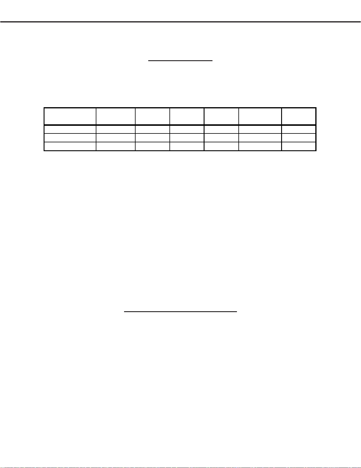
This service manual provides service instructions for the V33 chassis. The specific models for this chassis type,
dimensions and weight are listed below. Service personnel should read this manual thoroughly before servicing these
chassis.
MODEL CHASSIS HEIGHT WIDTH DEPTH WEIGHT
WD-52631
WD-57731
WD-65731
This service manual includes:
1. Assembly and disassembly instructions for cabinet and chassis components.
2. Servicing of the Lenticular Screen and Fresnel Lens.
3. Servicing printed circuit boards (PCBs).
4. Electrical and Mechanical adjustments.
6. Chip parts replacement procedures.
7. Circuit path diagrams.
The parts list section of this service manual includes:
1. Cabinet and screen parts.
2. Electrical parts.
Schematic and block diagrams of the above listed models are included in this service manual for better understanding
of the circuitry .
V33 33.3" 47.1" 17.1" 87.2 lbs 250W
" 36.3" 51.5 " 18" 96 lbs 250W
" 40.8" 58.5" 19.8" 103.7 lbs 250W
POWER
USAGE
PRODUCT SAFETY NOTICE
Many electrical and mechanical parts in television receivers have special safety related characteristics. These characteristics are often not evident from visual inspection nor can the protection afforded by them necessarily be obtained by
using replacement components rated for higher voltage, wattage, etc.
Replacement parts which have special safety characteristics are identified in this service manual.
Electrical components having such features are identified by shading on the schematic diagram and parts list of this
service manual, and by marking on the supplementary sheet for this chassis to be issued subsequently . Therefore,
the replacement for any safety part should be identical in value and characteristics.
Page 5
Page 6
MODEL: WD-52631 / WD-57731 / WD-65731
SAFETY PRECAUTIONS
NOTICE: Observe all cautions and safety related notes located inside the receiver cabinet and on the
receiver chassis.
WARNING:
1. Operation of this receiver outside the cabinet or with the cover removed presents a shock hazard
from the receiver's power supplies. Work on the receiver should not be attempted by anyone who is
not thoroughly familiar with the precautions necessary when working on high voltage equipment.
2. When service is required, observe the original lead dress. Where a short-circuit has occurred, replace
those components that indicate evidence of overheating.
SAFETY PRECAUTION
To protect your eyes, do not look directly into the lamp, or light coming directly from the lamp, lens or
mirror.
Leakage current check
Before returning the receiver to the customer, it is recommended that leakage current be measured according to the
following methods.
1. Cold Check
With the alternating current (AC) plug removed from the AC source, place a jumper across the two AC plug
prongs. Connect one lead of an ohm meter to the AC plug and touch the other lead to each exposed metal part
(i.e. antennas, handle bracket, metal cabinet, screw heads, metal overlay , control shaf ts, etc.), particularly any
exposed metal part that has a return path to the chassis. The resistance of the exposed metal parts having a
return path to the chassis should be a minimum of 1 Meg Ohm. Any resistance below this value indicates an
abnormal condition and requires corrective action.
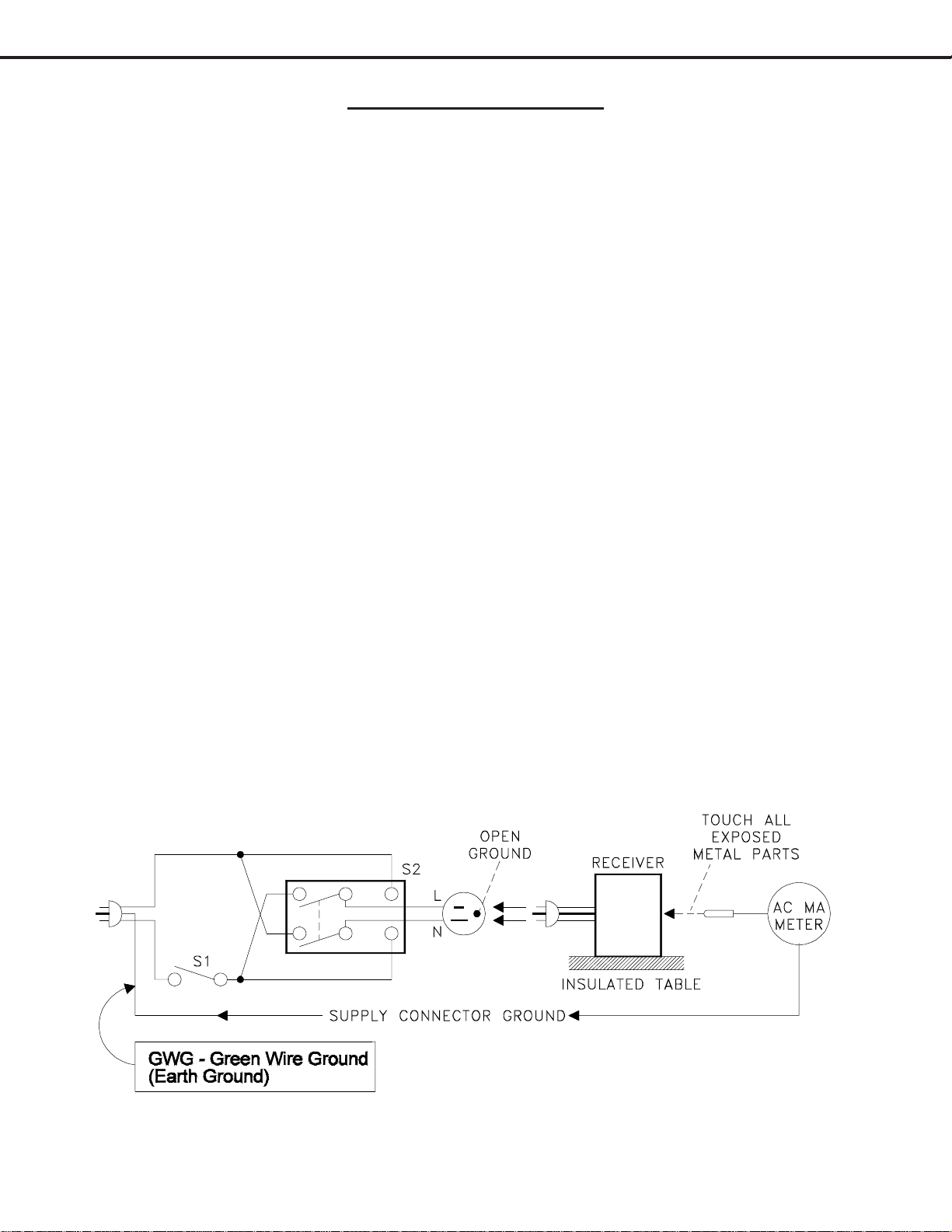
2. Hot Check ...Use the circuit shown below to perform the hot check test.
1. Keep switch S1 open and connect the receiver to the measuring circuit. Immediately after
connection, and with the switching devices of the receiver in their operating positions, measure the
leakage current for both positions of switch S2.
2. Close switch S1, energizing the receiver . Immediately after closing switch S1, and with the
switching devices of the receiver in their operating positions, measure the leakage current for both
positions of switch S2. Repeat the current measurements of items 1 and 2 after the receiver has
reached thermal stabilization. The leakage current must not exceed 0.5 milliampere (mA).
Page 6
Page 7

MODEL: WD-52631 / WD-57731 / WD-65731
Rear Cover Removal
Rear Cover Removal Procedure
1 ) Remove 8 screws (A) from the External Input frame.
2 ) Remove 10 screws (B) from the rear cover.
3 ) Pull the rear cover from the TV .
Chassis Disassembly
Chassis Removal from Cabinet
1 ) Remove two screws (a)
2 ) Disconnect all cables connecting to
the chassis.
3 ) Carefully slide the chassis out of the
Cabinet.
Img_0184.jpg
Page 7
a
a
Page 8
MODEL: WD-52631 / WD-57731 / WD-65731
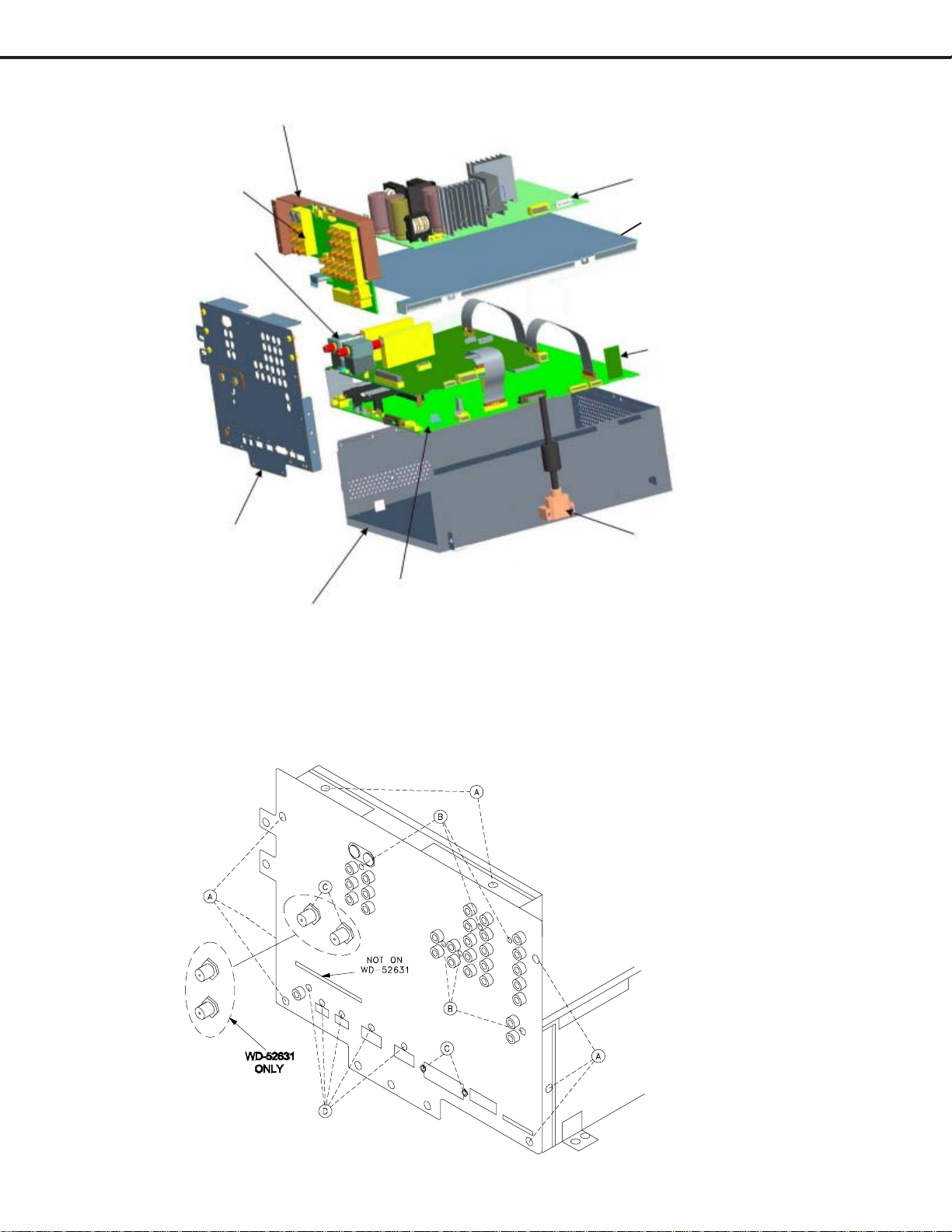
T erminal shield
Chassis (Exploded View)
PWB-TERMINAL
PWB-SIGNAL
Main T erminal cover
PWB-POWER
Chassis box cover
PWB-E2P
DVI connector
PWB-DM
Chassis box
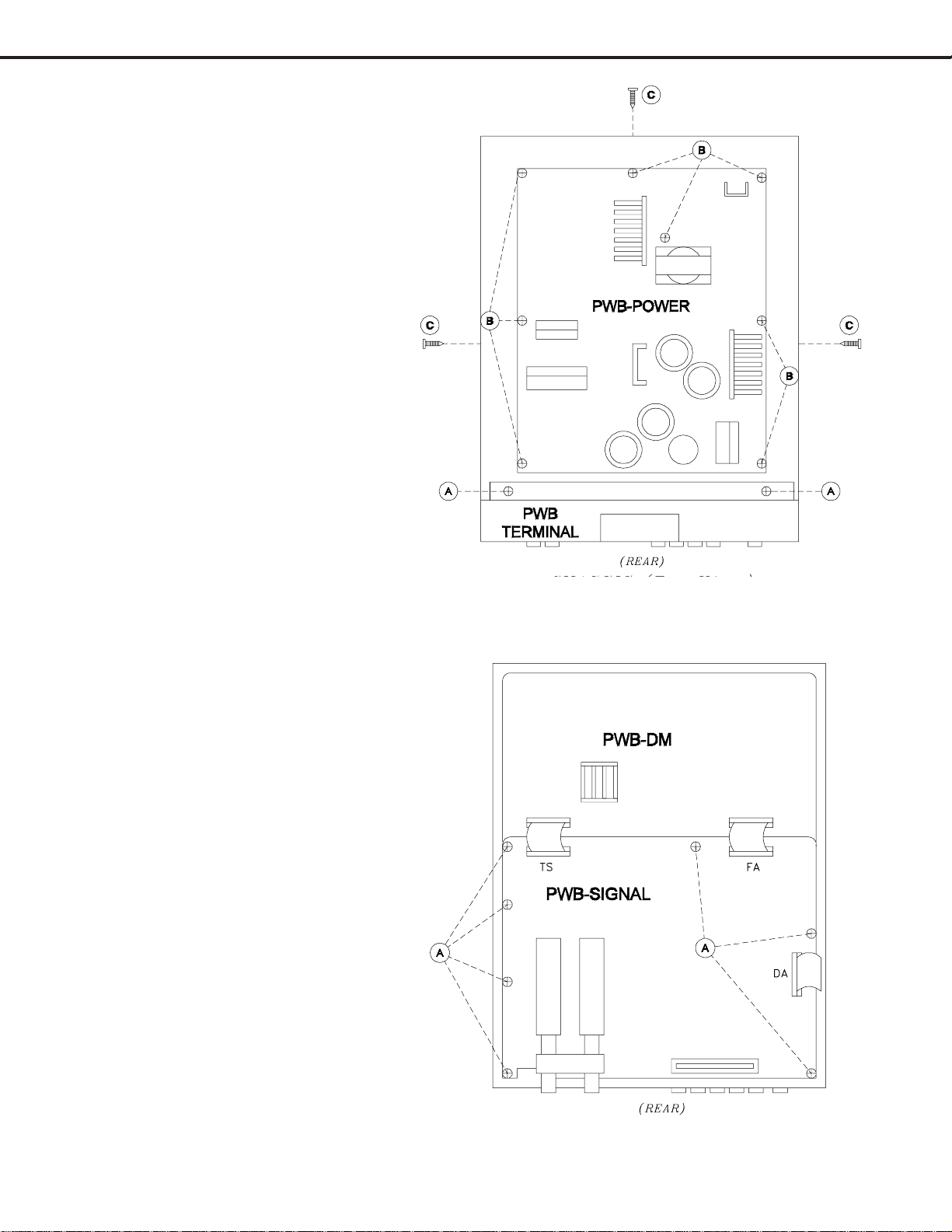
Main T erminal Shield Removal
1 ) Remove 8 screws (A), 6 screws (B) and 5 screws from the T erminal Shield.
2 ) Remove 4 nuts (C).
3 ) Pull the Terminal Shield from the chassis.
Page 8
Page 9
MODEL: WD-52631 / WD-57731 / WD-65731
PWB-TERMINAL Removal
After removing the T erminal Shield:
1 ) Remove 2 screws (A) from the
T erminal Cover .
2 ) Carefully pull upward to remove the
PWB-TERMINAL and Cover from the
chassis.
PWB-POWER Removal
1 ) Disconnect all lead to the PWB-
POWER.
2 ) Remove 8 screws (B) from the PWB-
POWER.
3 ) Lift the PWB-POWER from the
chassis..
Chassis Box Top Cover Removal
1 ) Remove 3 screws (C).
2 ) Lift the cover from the chassis box.
PWB-SIGNAL Removal
After removing the PWB-POWER and the
chassis box cover:
1 ) Remove 7 screws (A) from PWB-
SIGNAL.
2 ) Disconnect all cables going to the
PWB-SIGNAL.
3 ) Lift PWB-SIGNAL from the chassis
box.
Chassis (top view)
Page 9
Chassis (top view)
Page 10
MODEL: WD-52631 / WD-57731 / WD-65731
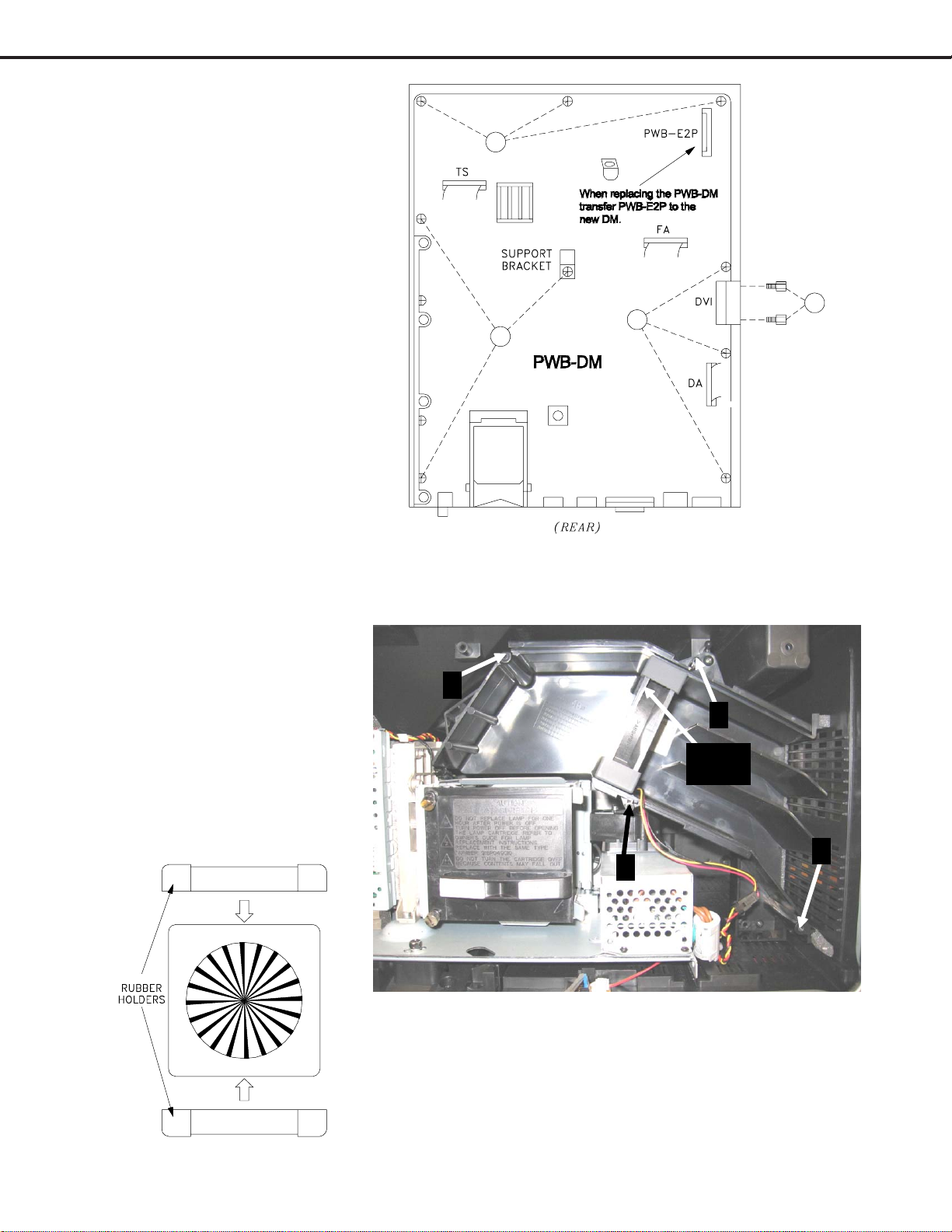
PWB-DM Removal
After removing PWB-SIGNAL:
1 ) Remove 9 screws (A) from the
PWB-DM.
2 ) Remove 2 hex screws (B) from
the DVI connector.
3 ) Lift the PWB-DM from the
chassis box.
If PWB-DM is replaced, transfer the PWB-E2P
from the old DM to the new DM.
Then perform the data transfer procedures
"Copy Light Engine E2PROM to DM"
and "Download WB Alignment to FMT"
described on page 25.
A
B
A
A
Chassis (top view)
Exhaust Fan Replacement
1 ) Remove 4 screws (A) and
remove the exhaust duct cover.
2 ) Slide the Exhaust Fan from the
duct and unplug the JF connector.
Note: Save the rubber cushions, they do not come with a
new fan.
3 ) When installing the fan ensure
the leads come out the bottom
of the fan as shown in the
picture.
A
A
Exhaust
Fan
A
A
Page 10
Page 11
MODEL: WD-52631 / WD-57731 / WD-65731
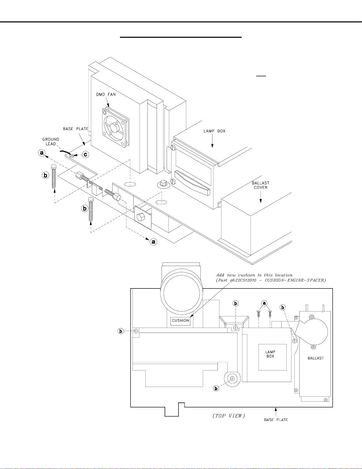
Optical Engine Removal
Engine (xHD5) Removal from cabinet
xHD5 Engine Removal Procedure
1 ) Remove 2 locking screws (b) and
ground screw (c).
2) Loosen one adjust screw (a). Less
adjustment will be required when the
Engine is installed.
3 ) Disconnect all leads to the Engine,
Lamp Box and Ballast.
4 ) Carefully slide the Engine, with the
bottom plate from the cabinet.
Engine Removal from base plate
Removing the xHD5
Engine from the Plate
1 ) Remove the 2 screws
(a), and 4 screws (b).
2 ) Carefully lift the
engine from the base
plate.
3 ) Add a new cushion
behind the lens.
After Replacing Engine
Copy Engine Data to DM
Refer to data transfer on page 24.
Note: The Engine has no individual
service parts available. Attempting
to disassemble the Engine may void
the warranty.
NOTE: After Engine replacement, verify the foam gasket around the lens is properly positioned and that it does not block
the light path. The side portholes of the cabinet can be used for visual confirmation.
Page 11
Page 12
MODEL: WD-52631 / WD-57731 / WD-65731
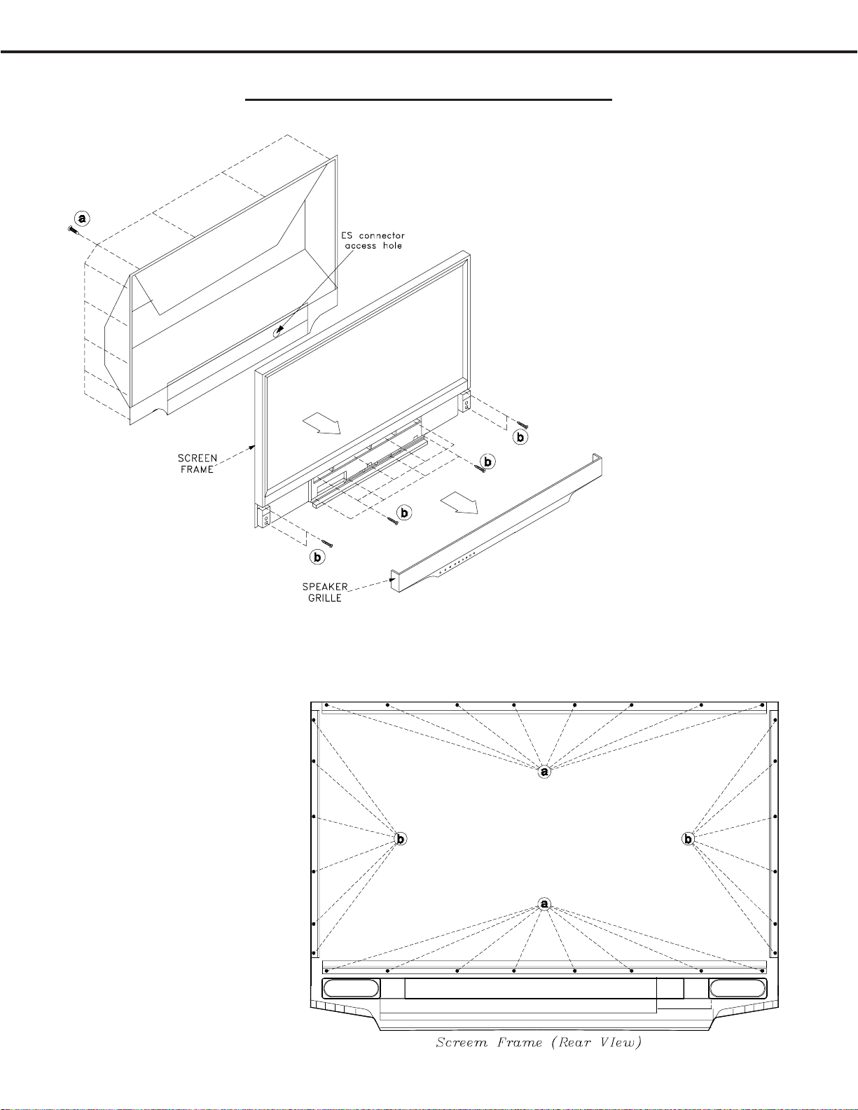
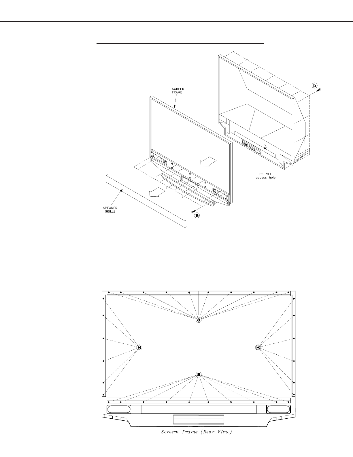
WD-52631 Models Front Disassembly
52” Models Screen Frame Removal
1 ) Pull off the Speaker Grille.
2 ) Remove all screws (a) from the upper rear
cover (except one at an upper corner).
3 ) Remove 12 screws (b) from the front of the
screen frame.
4 ) Remove the one remaining screw (a)at the
upper rear corner. Carefully pull the Screen
Frame from the TV and unplug the ES
connector..
WD-52631 Screen Removal from the Frame
1 ) From the rear of the
Screen Frame remove 16
screws (a) from the top
and bottom rails.
2 ) Remove 6 screws (b) from
each side rail.
3 ) Carefully lift the Screen
assembly from the
Frame.
Page 12
Page 13
MODEL: WD-52631 / WD-57731 / WD-65731
WD-57731 & WD-65731 Front Disassembly
57” & 65” Models Screen Frame
Removal
1 ) Pull off the Speaker Grill.
2 ) Remove all the screws (b) from the
upper rear cover (except one at an
upper corner to support the frame).
3 ) Remove 10 screws (a) from the
front of the screen frame.
4 ) Remove the remaining screw (b)
(supporting the frame). Carefully
pull the Screen Frame from the TV
and disconnect the ES and LE
connectors.
57” & 65” Models Screens Removal from Frame
1 ) From the rear of the Screen Frame remove 20 screws (a) from the top and bottom rails
2 ) Remove 6 screws (b) from each side rail.
3 ) Carefully lift the Screen assembly from the Frame.
Page 13
Page 14

MODEL: WD-52631 / WD-57731 / WD-65731
Screen Replacement
CAUTION: Wear gloves when handling the Lenticular Screen and Fresnel Lens.
This prevents cuts and finger prints. Do not place Fresnel Lens in the sun.
This may cause fire and heat related injuries.
Lenticular Screen and Fresnel Lens Removal
1 ) Remove the top, bottom and side HOLDER-SCREEN rails and their cushions from the Screen Frame.
2 ) Lift the screens as a single unit from the frame.
2. Separate the Lenticular Screen and Fresnel Lens.
Note: When separating the Lenticular Screen from the Fresnel Lens, use caution
while prying the Screen and Lens apart. Use a slot type screw driver, and
remove the pressure sensitive double sided tape.
Lenticular Screen and Fresnel Lens Replacement
1 ) Apply LENS-TAPE along the rear top edge of the Lenticular Screen.
2 ) Place the Fresnel Lens on top of the Lenticular Screen, and apply pressure along the top edge.
3 ) Place the screens in the screen frame and reinstall the cushions, top, bottom and side rails.
NOTE: The Lenticular Screen label must face the front and the Fresnel Lens label face the rear.
4 ) Reverse the Screen Removal Procedure and insert the screens in the Bezel.
Page 14
Page 15
MODEL: WD-52631 / WD-57731 / WD-65731
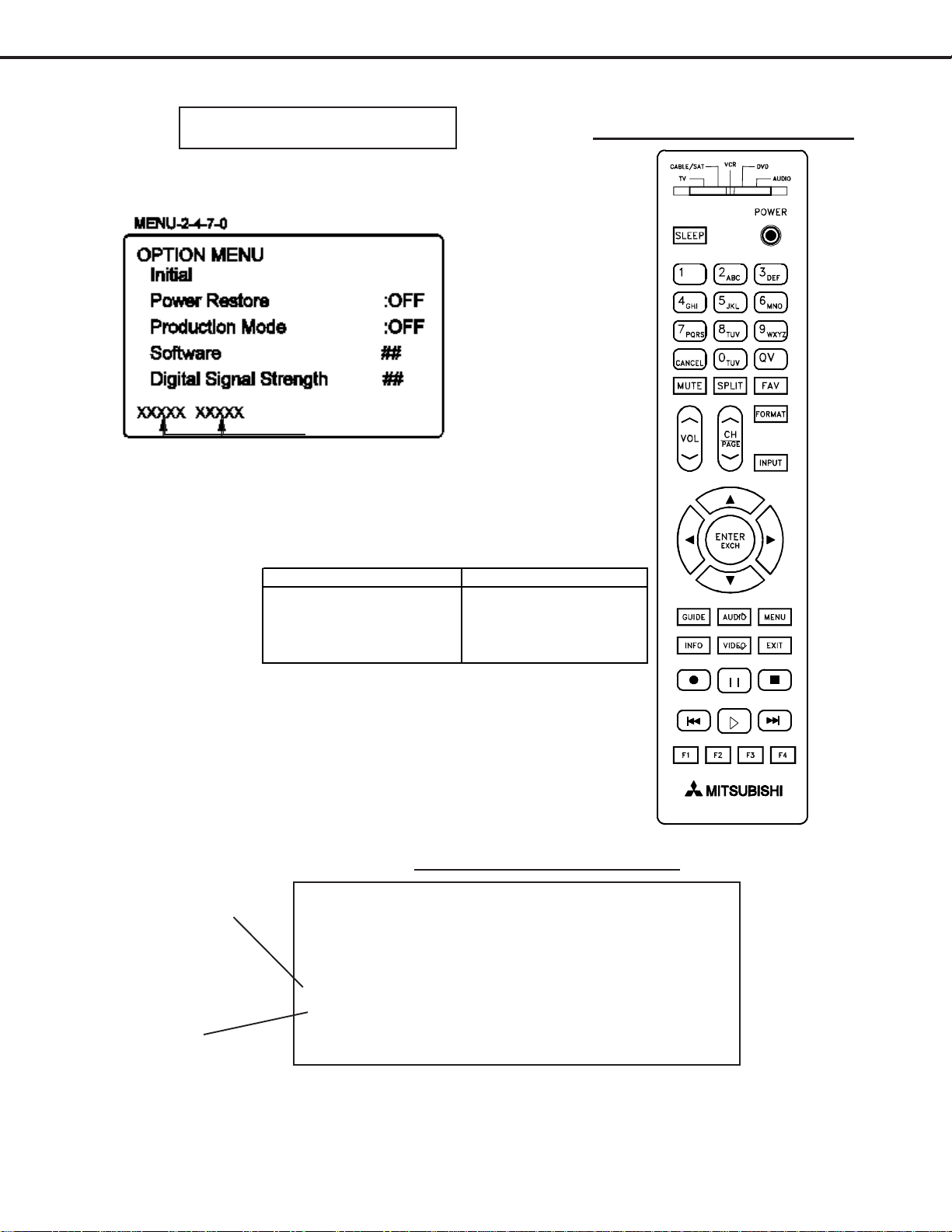
OPTION MENU
1. Press the “MENU” button on the remote hand unit.
2. Press the buttons “2”, “4”, “7” and “0” in order.
(The screen will change to the option menu.)
T otal Lamp ON Time
V33 Remote Button Name Changes
Previous Model Name New Name
HOME EXIT
PIP/POP SPLIT
SQV FAV
DEVICE INPUT
V33 REMOTE CONTROL
Digital Signal Strength
1. Tune to a Digital Channel
2. From the Option menu scroll down and highlight Digital Signal Strength
3. Press Enter
Example using CableCARD on ANT1
Signal Quality
Index (0-100)
Signal Noise
Ratio
SNR Recommended Levels:
VSB = 15 to 35
64 QAM = 22 to 34
256 QAM = 27 to 37
Frequency(MHz): 597 0 75.2
Signal Level: 8 0 0
Modulation: 256 QAM Unknown
Carrier Lock: Locked Unknown Locked
SQI: 100 0
SNR: 34.3 0 23.77
Correctable errors: 0 0
UnCorrectable errors: 0 0
Tuner 0 Tuner 1 OOB Tuner
Page 15
Page 16

MODEL: WD-52631 / WD-57731 / WD-65731
A
Front Panel Initialization (new in the V33)
While the unit is ON, pressing the FORMA T and INPUT buttons simultaneously will immediately start the Initialization
sequence. The TV will reboot once the initialization sequence is completed. Front Panel Initialization will reset ALL
user settings to the factory setting.
SERVICE TIP:
Many customer generated symptoms, intermittent symptoms or no symptom found can be resolved by system reset
or initialization. Before visiting the customer’s home ask the customer 1st to try the System Reset button on the
control panel and if this does not resolve the issue, then they can use the front panel initialization by pressing the
FORMA T and INPUT buttons simultaneously
NOTE: During Initialization, the set will
reboot. Wait until the Power LED stops
flashing before unplugging or powering
ON the TV .
RESET / INITIALIZE GUIDE
Reset Name When to use How to use Result in g Actio n
Remote Co n trol TV
Layer Reset
Returns th e rem o te c o ntro l T V
layer to normal operation.
(1)
Set the slide switch to TV posi t ion.
(2)
Press and hold the
(3)
flashes twice then release the button.
(3)
Enter the code
POWER
0 0 9 3 5
.
button until it
Once the valid code has been entered
and confirmed, the remote control has
been reset.
Remote Co n trol TV
Volume/Mute
functions
/V Memory Reset,
single in put
A/V Reset, all
inputs
System Reset To reset the TV when it does not
TV Reset To reset all customer settings
Initialize - User
Level
Returns the volume and mute
functions of the remote control to
TV volume and mute for TV,
Cable/Sat, VCR and DVD layers
after the audio lock for AV
Receivers feature has been used.
When the audio and or video
settings for a single input seems
to incorrect
To reset audio and video
adjustments for all inputs to the
original factory settings.
turn on or off, does not respond
to the remote control, front panel
buttons or has audio but no
video.
To reset all consumer adjusted
settings and memories to the
original factory defaults.
(1)
Set the slide switch to TV posi t ion.
(2)
Press and hold the
(3)
flashes twice then release the button.
(3)
Enter the code
MENU --> Audio/Video--> AV Reset All Audio and Video settings for the
While viewing the TV, press the front panel
GUIDE
buttons
time.
Press the
front panel with a pointed object such as
the point of pencil or end tip of a paperclip.
Press
Press
front control panel at the same time.
SYSTEM RESET
MENU-1-2-3-ENTER All customer settings except V-Chip are
FORMAT
POWER
9 9 3 VOL UP
FORMAT
and
INPUT
and
button until it
.
at the same
button on the
buttons on the
The remote will now operate the TV's
volume and mute when the slide switch
is in the TV, CABL E/SAT, VCR or DVD
positions.
individual input are reset except for the
Listen To
Balance
All Audio and Video settings including
Listen To
Captions
are returned to the original factory
settings.
The changes you made most recently,
before using the SYSTEM RESET, may
be lost. Changes you made previously,
howev er, are not lost .
reset.
All memories and settings outlined in
the Owner's Guide will need to be set
again.
Language,
and
Closed Caption
and
Language, Closed
and
settings and
Format
audio
settings.
settings
Initialize - Service
Level
Factory Restore To recover from data/adjustment
To reset all consumer adjusted
settings and memories to the
original factory defaults.
errors in the ISF menu
MENU + 2470
press
MENU + 2457 + 0
FACTORY DEFAULTS and press ENTER
. Highlight
ENTER
INITIALIZE
. Highlight RESTORE
and
All memories and settings outlined in
the Owner's Guide will need to be set
again. Also erases V-CHIP password
All service, user, ISF data is set back to
factory defaults.
Page 16
Page 17

MODEL: WD-52631 / WD-57731 / WD-65731
INITIAL DEFAULT SETTINGS
Setup Menu
Langua ge (Idioma) English Start Time -- Lock Time 12:00pm
Memorize Channels -- Day -- Unlock Time 12:00pm
Ant1 Air -- Record List -- Front Panel Lock Off
Ant1 Cable -- Audio/Video
Ant2 Air -- Antenna 1 A/V Memory Reset Ant-1
Ant2 Cable -- Channel 2 Settings
Clock Memory Added Audio
Clock Setting Manual Name Blank Bass 50%
Time 12:00PM FAV Blank Treble 50%
Date 1/1/2006 Signal Streng th (Depe nds on Balance 50%
Time Zone Eastern digital source) Surround Off
Daylight Savings Applies Listen To (Analog Only) Stereo
Timer Gray out Analo g Captions On if Mute Level Sound On
Timer Off Background Gray Language (Digital O nly) Englis h
Day Daily Digital Captions On if Mute Video
Time 1 2:00PM Appearance Default Picture Mode Brilliant
Device ANT-1 Digital Settings Contrast 100%
Channel 2 Font Font 3 Brightness 50%
Demo mode Grey out (mode off) Size Large Color 50%
Software Version V33 XXX.XX Color White Tint 50%
Clear Thought Menu
Edit Review Opacity Translucent Brilliant Color Temp High
Input Name -- Perfect Color Perfect color
Input-1 -- U.S Ratings (DefineEdge)
Input-2 -- US Ratings Off Video Noise Medium
Inout-3 -- TV Rating TV-PG Video Mute On
Comp-1 -- FV-Fantasy Violence unchecked TV Speakers On
Comp- 2 -- D-Sexual Dialog unch ecked Film Mode Auto
HDMI-1 -- L-A dult Language unchecked
HDMI-2 -- S-S exual Situat ions unchecked
AV Receiver Setup Off, Learn&Connect V-Violence unchecked
buttons grayed out Programs Not Rated uncheck ed
Icon Order Ant-1, Ant-2, Input-1, Movie Rating PG
Input-2, Input-3, V-Chip Time
Comp 1 & Comp-2 Start 12:00pm
PC DVI Dig ital Stop 12:0 0pm
Record Other Rati ngs
Record Other ratings Off
Channel 2 Rating Group TBD
Record to -- Rating TBD
Duration 1 hr. Lock by Time Off
Channel
Captions Menu
Back ground Bla ck Shar pness 50%
Parent Lock Menu
TV Volume
DW Source
DW Posi tion
PIP/POP Format
Format
Ant-1,2 (480I/480P)
Ant-1,2 (HD Digital)
Input-1,2,3
Comp-1,2,3
HDMI-1,2 (Video)
1394 Devices
DVI-I PC
30%
ANT 1 002
Right half
Double Window
Stretch
Standard
Standard
Standard
Standard
Standard
Standard
Page 17
Page 18

A/V DEFAULTS
MODEL: WD-52631 / WD-57731 / WD-65731
A/V Memory
Picture Mod e Brilliant Brilliant Brilliant Brilliant Brilliant n/a
Brilliant Contrast
Brilliant Brightness Center Center Center Center Center Center
Color Center Center Center Center Center n/a
Tint
Sharpness Center Center Center Center Center n/a
Colo r Te mp.
Perfect Color
Video Noise Medium Medium Medium Medium Medium n/a
Film Mode (Auto) On On On N/A On n/a
Bass
Treble Center Center Center Center Center Center
Balance Center Center Center Center Center Center
Surround
Listen To Stereo n/a n/a n/a n/a n/a
Level Sound
Language (Digital Only)
Vertical Positi on n/a n/a n/a n/a n/a Center
Horizontal Position n/a n/a n/a n/a n/a Center
Fine Detail
Ant 1
Ant 2
MAX MAX MAX MAX MAX MAX
Center Center Center Center Center n/a
High High High High High High
Manual/
Center
Center Center Center Center Center Center
Off Off Off Off Off Off
On On On On On On
English n/a n/a English n/a n/a
n/a n/a n/a n/a n/a Center
INPUT
1/2/3
Manual/
Center
COMP 1 / 2
Manual/
Center
1394
(connected)
Manual/
Center Manual/ Center
HDMI 1/2
(Video)
DVI-I(PC)
Manual/
Center
A. A/V Memory
Each of the external inputs has it’s own Audio/Video Memory. A change in an A/V setting at a specific input is
stored in memory for that specific input.
B. A/V Reset
1. Pressing the front panel “GUIDE” and “FORMA T” buttons at the same time initializes all A/V Memories.
2. The AV Reset in the user’s menu initializes only the selected input’s A/V Memory.
Page 18
Page 19
MODEL: WD-52631 / WD-57731 / WD-65731
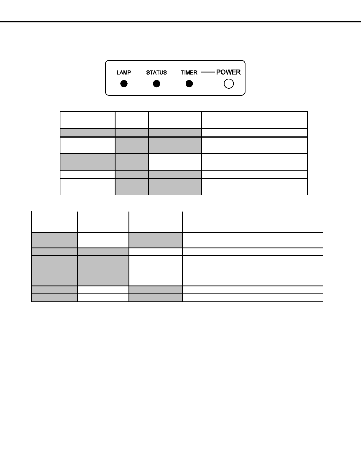
Power/Timer
Indicator
Status
Indicator
Lamp Indicator Condition
Off
Off Off Off (standby)
Blinking green
fast
Off Off Initialization (45-60 seconds)
Off
Off Blinking green
slow
Lamp cooling for 1 min after PTV
off
Green Off Off Power On
Blinking green
slow
Off Off Power On Timer is set
NORMAL LED INDICATIONS
Power/Timer
Indicator
Status Indicator Lamp Indicator Condition
High Temperature - check ventilation air flow.
Temperature sensor is disconnected.
Off Off Blinking yellow Lamp cover is open.
Lamp failure
Off
Off
Red*
Lamp fails to turn on
Lamp turns off during P-On
Lamp is broken
Off Blinking Red Off Fan Stop
Off Red. Off Circuit failure. (Run Error Code Check)
* A red Lamp LED only occurs after 3 attempts to light the lamp. Each attempt (pressing POWER)
must be at least 65 seconds apart. During each attempt ballast striking may be audible.
ABNORMAL LED INDICATIONS
Off Yellow Off
LED Indicator Diagnostics
The front panel LEDs provide an indication of the sets operation, and the possible cause of a malfunction. There are three
front panel LEDs, Power, Status and Lamp. The LED display shows the current status or indicates a possible
malfunction.
3. Error Code Operational Check
Note: The TV must be in Shut Down and not have been switched Off, to perform the Error Code Opera-
Pressing the front panel INPUT and MENU buttons at the same time, and holding for 5 seconds,
activates the Error Code Mode. The TIMER LED flashes denoting a two digit Error Code, or indicating no
problem has occurred since the last Initialization.
Note: The front panel buttons must be used, NOT those on the Remote Control.
tional Check. When the TV is switched Off, the code automatically resets to 12 No Error.
The number of flashes indicates the value of the MSD (tens digit) of the Error Code.
The flashing then pauses for approximately 1/2 second.
The LED then flashes indicating the value of the LSD (ones digit) of the Error Code.
The Error Code is repeated a total of 5 times.
Example: If the Error Code is 23, the LED will flash two times, pause, and then flash three times.
Page 19
Page 20

4. Error Codes
The Error Code designations indicating malfunction, or no malfunction, are listed below:
MODEL: WD-52631 / WD-57731 / WD-65731
ERROR CODES
Code
12
32
(1)
34
36
37
38
39
42
44
48
(2)
57
58
59
(3)
61
(4)
66
Description
No Error found
Lamp cover is open.
Lamp turns Off while the TV is playing.
(Lamp failure)
(Lamp Enable signal from engine is lost)
Lamp ballast fan failed.
Engine (DLP) fan failed.
Lamp temperature abnormally high.
Remove Lamp to check filter.
DMD temperature abnormally high.
Exhaust fan failed.
Check for disconnected DVI cable between PWB-DM and Engine.
Engine power supply short is detected.
Ballast communication problem (ballast to chassis)
Signal Short is detected
DM short is detected
No LAMP-EN output from the engine to the ballast
Lamp did not turn on at P-ON sequence
(No Lamp inserted)
(Disconnected cable between ballast and lamp)
(Lamp-Enable goes to DM but not to Ballast)
Code 34
Code 57
Code 61
Code 66
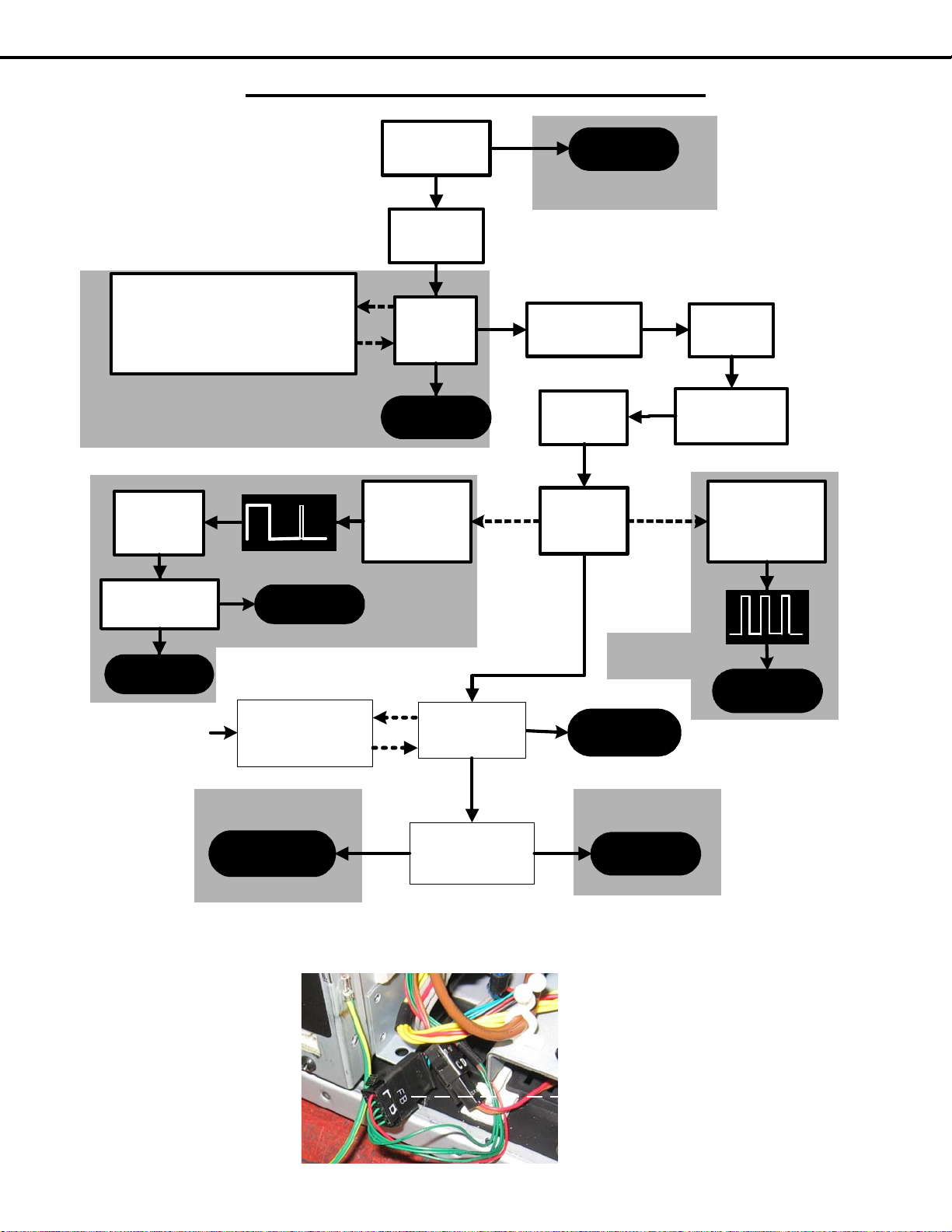
Lamp T
Use the above Error Code Table, the Lamp Control Block diagram, and the Troubleshooting flow chart on the following pages
to determine is a lamp problem is due to the Lamp, Ballast, Power Supply or Light Engine.
(1)
- Lamp Enable is generated to activate the Lamp
(2)
- Lamp Enable is generated during P-ON sequence, but no Lamplit signal is received from the Ballast.
(3)
- No Lamp Enable is received at the DM and Ballast.
(4)
- Lamp enable is received at the DM but not at the Ballast.
roubleshooting
Page 20
Page 21
MODEL: WD-52631 / WD-57731 / WD-65731
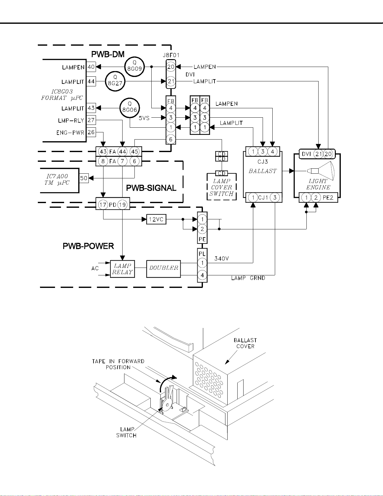
Lamp Control Block Diagram
Disabling the Lamp Switch (when the back is removed)
Page 21
Page 22
MODEL: WD-52631 / WD-57731 / WD-65731
• Install Lamp Cover with no Lamp
• Tape Lamp Switch Closed
• Monitor Ballast spark gap.
• Press "POWER'
• Spark gap arc?
Press
"POWER"
PE Connector
Pins 1 & 2=12V
Ballast
DC Supply?
Check
PWB-POWER
Replace
Lamp
Check
PWB-POWER
• H for 5 sec.
• L for 10 sec.
• H for 1 sec>
• Stays Low
PL (1to4)=340V
FB pin 3=5vs
Replace
Ballast
Replace
Engine
• H for 4 sec.
• L for 10 sec.
• Repeats
several times
Replace
Lamp
Install Lamp
& Lamp Cover
Check
Ballast
Striking
Replace
Lamp
Check
LAMP-EN
(FB pin 4)
Yes
NG
No
OK
Yes
Pulses
No
No Pulse
Pulses
Yes
Yes
ENG-PWR
(PD-17)
Check
Engine
Power
Code 61
Code 61
Code 34
Code 34
Code 57
Code 57
Check
Continuity
FB-4 to DVI-20
Check
DVI cable & DM
Open
OK
Code 66
Code 66
Lamp Lights
then goes out
Lamp does
not Light
Code 66
Code 66
Check Cable
Connections
DVI, FB & CJ3
Circuit
Problem
OK
Code 66
Code 66
Lamp T
roubleshooting Flow Chart
Page 22
FB Interconnect
Page 23
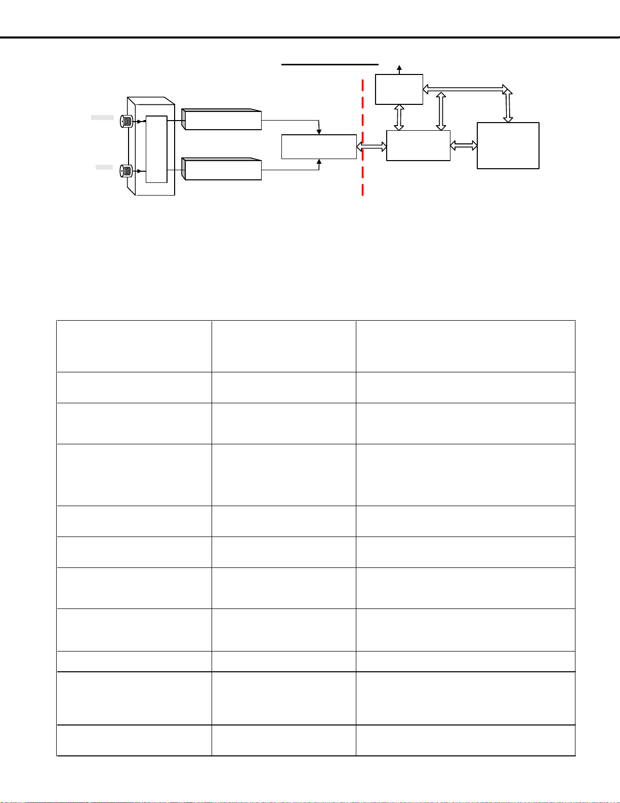
MODEL: WD-52631 / WD-57731 / WD-65731
OOB Tuner (TU-101)
Main Tuner (TU-100)
(Cable/ ATSC/NTSC)
PCMCIA
SLOT
(CableCARD)
Air
in
Cable
Matrix SW
DEMODULATOR
IC1500
POD I/F
IC8506
XILLEON
IC8001
SIGNAL-PWB DM-PWB
Data Bus
TS &
Data
TS &
Data
TS &
Data
Data
Bus
To Engine
SYMPTOM
POSSIBLE CAUSE(S)
POSSIBLE RESOLUTIONS
1
No channel map appears when pressing
guide button (TVGuide disabled)
Cable is not connected to ANT1 -orOOB data is not received correctly
1) Verify cable is connected to ANT1
2) Re-install/Replace CableCARD
3) Verify signal level and signal noise level
4) Contact Service Provider
5) Check TU101 for proper function/Replace Signal PWB
2
Channel map does not change after card
is installed. (still showing basic cable
map)
CableCARD is not ’Initialized’ within
the service providers system. Contact service provider
3 Host ID screen does not appear
Signal and information not received by
TV
1) Verify cable is connected to ANT1
2) Re-install CableCARD
3) Replace CableCARD
4) Verify signal level and signal noise level
4
Error code received on screen. Error
codes are listed such as 161-x
Communication between TV and card
is lost or disrupted
1) Pull card from TV and wait 5 minutes. Then reinstall the
card and verify it is initializing properly.
2) Press INPUT & FORMAT keys on the front panel.
3) Replace CableCARD with new card
4) Try 3rd CableCARD
5) Replace DM-PWB
5
Individual channel cannot be received.
(example HBOHD is no video and no
audio but other HBO channels are OK)
The TV has no means to block
individual channels. Proper
authorization is not received.
Contact service provider
6
Certain tier of channels is not received.
(example: Premium channels or all HD
channels not received)
Authorizations to display scrambled
channels are sent via OOB data.
Contact service provider
7
Unable to tune to a channel. (example:
Pressing 1055 has no response and
stays on current channel)
1055 is not available in the channel
map. Channel map is sent via OOB
from the service provider.
Verify OOB is locked. If OOB is locked, verify channel
should be received. If not locked, troubleshoot for OOB
failure on SIGNAL PWB and/or with service provider.
8
When using SA card channels changing
automatically and random message
about upgrade in process. (Channels are
often like 10,000 to 50,000)
CableCARD firmware is out of date
and being upgraded by service
provider.
If this process continues more than 60 minutes, contact
the service provider for updated card
9
Periodically encrypted channels become
unavailable.
Card is hung Unplug card or AC or perform initialize
10
Only Analog channels can be viewed. All
digital/encrypted channels are
unavailable
Proper authorization is not received or
TV cannot display digital video
1st test for QAM clear channel (often network channels are
provided free), if no QAM clear channel is available
remove the card and memorize channels. Verify that a
digital channel can be viewed. If known digital channel
cannot be viewed suspect SIGNAL
11
ChannelView does not list program
content or channel call letters
This information is provided in the
form of OOB data tables and is sent at
the discretion of the service provider
Contact service provider
CableCARD
Cable providers send QAM64 and/or QAM256 through
the coax cable to the TVs tuner. Once converted to IF it is
demodulated to an MPEG transport stream (TS). If a card is
present in the PCMCIA slot the TS will be passed to the card
and returned back to IC8506 and then finally sent to the Xilleon
processor. If there is no card present in the card slot and the
tuner is tuned to a QAM channel the TS will pass directly from
the POD interface IC directly to the Xilleon for processing.
Cable providers typically have both encrypted
and unencrypted channels. If the Xilleon receives an
encrypted TS it will ask the CableCARD to unscramble
the stream. The card will only unscramble the TS if it
receives the proper authorizations to do so. Those
authorizations are received via Out-of-Band data (OOB).
The OOB contains information about authorizations,
channel maps and more.
Page 23
Page 24

MODEL: WD-52631 / WD-57731 / WD-65731
SERVICE ADJUSTMENTS
There are only 4 Service Adjustment s required in these models:
T wo Electrical Adjustments
• Horizontal Centering
• Vertical Centering
T wo Mechanical Adjustments
• Picture Rotation
• Vertical Keystone Distortion
Measuring equipment and Jigs
• No additional Test Equipment is required.
• Conventional Electrical Hand T ools.
Test signal
An internally generated Test Signal is used, no additional external
signals are required.
Circuit Adjustment Mode
On these models, the Circuit Adjustment Mode is used only for:
• Test Signal activation
• Horizontal Centering
• Vertical Centering the following adjustment s may only
be performed using the remote hand unit.
1. Activating the adjustment mode
1. Press the “MENU” button on a remote hand unit.
(The “MENU” display will appear .)
2. Press the buttons “2”, “4”, “5” and “7” in that order.
(The screen will change to the adjustment mode.)
If not changed to the adjustment mode, repeat steps
1 and 2.
2. T est Signal Activation
When in the Circuit Adjustment mode, press “REWIND” on the remote control to activate the test p attern. This
pattern is used for both electrical and mechanical adjustments.
3. Adjustment Function Selection
Use the “AUDIO” button to select a specific Adjustment Function.
NOTE: The only Service Function on these chassis is the “fmt” function.
3. Adjustment Selection
Use the “VIDEO” button to select a specific electrical adjustment, “1 HPOS” or “2 VPOS”.
4. Adjusting Data
After selecting an adjustment item, use the “UP” and “DN” buttons to change adjustment data.
• If the “UP” button is pressed, the adjustment data increases.
• If the “DN” button is pressed, the adjustment data decreases.
5. Saving data
Press “ENTER” to save the adjustment data in memory .
The display characters go red for approximately one second in this step.
Note: If the circuit adjustment mode is terminated without pressing
“ENTER”, changes in adjustment data are not saved.
Page 24
Page 25

MODEL: WD-52631 / WD-57731 / WD-65731
6. T erminating the circuit adjustment mode
Press the “MENU” button on the remote hand unit twice to terminate the adjustment mode, or press “EXIT” once.
Note: The adjustment mode can be also terminated by turning the
power off.
Data Transfer
1 ) Enter the Service Adjustment Mode ... Press “MENU-2-4-5-7”
2 ) Press “0” when in the Service Mode ... Four choices appear at the top of the screen.
DATA TRANSFER
Display Description
Copy Engine E2 P R OM to DM T ransfers E ngine data to DM E2P (after DM or Engine replacem ent)
Resto r e factory data Restores f actory set values
DOWNLOAD WB ALIGNMENT TO FMT Copies WB data from E2P to FMT (aft er PWB-DM replaceme nt)_
3 ) Use the UP & DN keys to highlight the desired choice, then Press “ENTER”
Page 25
Page 26

MODEL: WD-52631 / WD-57731 / WD-65731
Optical Engine Adjustments
T est Signal Activation
1) Press “MENU-2-4-5-7” (Service Mode)
2 ) Press “FF/FWD” to activate the overscan pattern shown below.
NOTE: There are 2 sets of 16 test patterns to help evaluate the performance of the chassis. Press
FF/FWD and REW/REV to toggle through the 16 patterns in each set. Press the Play button
to toggle to the next set of patterns.
Required Tools
8mm wrench
Prelminary
The only disassembly required to perform Optical Engine mechanical adjustments is the rear cover removal.
There are two mechanical adjustments vertical keystone and picture rotation. Adjustment s are made using the internal
test pattern shown above.
VERTICAL KEYSTONE
ADJUSTMENT
ROTATION
ADJUSTMENT
Page 26
Page 27

Adjustment Procedure
1) Remove rear cover.
2 ) Tape the Lamp Switch closed (Figure 1)
2 ) Activate the internal T est Pattern
“MENU-2-4-5-7” then press “FF/FWD”.
3 ) Refer to Figure 2 and loosen Locking
Screws [A-1] through [A-4].
.
MODEL: WD-52631 / WD-57731 / WD-65731
Optical Engine Adjustments
Figure 1: Lamp Swtich
Figure 2: Locking & Adjust Screws
Page 27
Page 28

MODEL: WD-52631 / WD-57731 / WD-65731
Rotation Adjustment
• Loosen [A-4] and adjust [A-3] to rotate the picture clockwise.
• Loosen [A-3] and adjust [A-4] to rotate the picture counter clockwise.
Vertical Keystone Adjustment
Rotate [A-7] to remove any vertical keystone distortion.
• Rotate [A-7] counter clockwise to increase width at the top of the picture.
• Rotate [A-7] clockwise to increase width at the bottom of the picture.
NOTE: Picture vertical position may shift during keystone adjustment
After Making Adjustments:
1 ) Tighten locking screws [A-3] and [A-4], hand tight only .
2 ) Tighten locking screw [A-1]. Torque to 29Kg/cm (minimum).
3 ) Tighten locking screw [A-2] . Torque to 29Kg/cm (minimum).
Page 28
Page 29

Electrical Adjustments
MODEL: WD-52631 / WD-57731 / WD-65731
[Format Circuit]
Horizont/Vertical Position
Adjustment
Measuring
Test Point
Ext. Trigger
Measuring
Input Signal
Input Termi
----
------
-----Internal Test Pattern.
Video
Purpose:
Symptom:
1. Press “MENU-2-4-5-7”, activates the Service Mode..
2. Select the “FMT” function (AUDIO button).
3. Press “FF/FWD”, activates the Overscan Test Pattern
4. Select “Item 1” HPOS (VIDEO button).
5. Use the ADJUST buttons to center the picture horizontally.
6. Press ENTER to save the new setting.
7. Select “Item 2” VPOS (VIDEO button).
8. Use the ADJUST buttons to center the picture vertically.
9. Press ENTER to save the new setting.
10. Press MENU to exit the Service Mode.
T o center the picture on the screen.
Picture is off center .
Page 29
Page 30

MODELS: WD-52631 / WD-57731 / WD-65731
Using Lead Free Solder
Pb Solder
The above symbol indicates Lead (Pb) Free solder was
used during the construction of PWBs. Only Lead
Free solder should be used when servicing these
PWBs.
Solder must be compatible with that used by the
manufacturer. Leaded solder can not be used on
PWBs manufactured with Pb-free solder. The Mitsubishi standard for service requires the use of Tin-SilverCopper (Sn-96.5, Ag-3.0, Cu-0.5). It can be obt ained
through the Parts Department.
Order part number: PB FREE SOLDER
Lead Free solder has a higher melting point, and does
not “wet” as well as leaded solder. This means it does
not adhere as readily to the solder iron tip, and the
surface to be soldered. To counteract this, the flux
used is more corrosive.
The following cautions must be taken when using Pb
Free solder.
• Higher temperatures can cause the PWB to
warp, detaching surface mount
components.
• Higher temperatures may
cause thermal damage to
components.
• Higher temperatures can cause
plastics, such as connectors,
relays, LEDs electrolytic
capacitors, etc. to melt or
warp.
• Higher temperatures can cause
surface oxidation resulting in
poor solder spread-ability and
wet-ability.
Pb-Free
Phase Definition Display
Phase-1 PCB's constructed using
Pb-free solder.
Phase-2 Solder, PCB surface
finishing and component
lead plating is Pb-free.
Components may have
internal Pb.
Phase-3 Solder, PCB surface
finishin
are Pb-free. (100% Pbfree)
• The flux is more corrosive.
• The time required for a good solder connection may
take longer.
• Poor wet-ability can cause solder balls.
• Higher temperatures can cause flux spattering.
• Soldering iron tip life is shortened.
• Dull finish solder joints (not shiny) can appear to be
a “cold” solder joint.
In general a tip temperature of 700° F will usually provide
good results.
Displays used to indicate Pb-free
PCBs will be marked, indicating the level of Pb-free construction. Table 1 defines the levels by phase and shows
the different symbols that will be displayed on the PCB.
Additionally , a PCB constructed using Pb-free solder may
be simply marked LFS.
When possible, the indication will be placed close to the
part number that is screened onto the PCB (not the part
label). Figure 1 is an example of a PCB showing the
display and its location.
Short Display (When the
area is too small)
Pb Solder
Pb Joints
g and components
Table 1: Pb-Free Phas es and Symbo ls
Pb PCA
Pb S
Pb J
Pb P
Pb-Free
Display
Figure 2: Pb-Fr ee display on PWB
PAGE 30
Page 31

MODELS: WD-52631 / WD-57731 / WD-65731
CHIP PARTS REPLACEMENT
Some resistors, shorting jumpers (0 Ohm resistors),
ceramic capacitors, transistors and diodes are chip parts.
The following precautions should be taken when replacing
these parts.
Cautions:
1. Use a fine tipped, well insulated soldering iron
and tweezers.
2. Melt the solder and remove the chip parts
carefully so as not to tear the copper foil from
the printed circuit board.
3. Discard removed chips; do not reuse them.
4. Do not apply heat for more than 3 (three)
seconds to new chip parts.
5. Avoid using a rubbing stroke when soldering.
6. Take care not to scratch, or damage the chip
parts when soldering.
7. Supplementary cementing is not required.
Chip Parts Removal (Resistors, Capacitors, etc.)
1. Grasp the part with tweezers. Melt the solder
at both sides alternately , and remove one side
of the part with a twisting motion.
2. Melt the solder at the other side and remove
the part.
Chip Parts Removal (T ransistors)
1. Melt the solder of one lead and lift the side of
that lead upward.
2. Simultaneously melt the solder of the other
two leads and lift the part from the PCB.
Replacement
1. Presolder the contact points on the circuit
pattern.
2. Press the part downward with tweezers and
apply the soldering iron as shown.
PAGE 31
Page 32

MODELS: WD-52631 / WD-57731 / WD-65731
REPLACEMENT PARTS
Parts Ordering
T o expedite delivery of replacement p arts orders, specify the following:
1. Model Number/Serial Number
2. Part Number and description
3. Quantity
Note: Unless complete information is supplied, delay in processing of orders will result.
Critical and Warranty Parts Designation
Critical Electrical Components are indicated by Bold Type in the Parts List, and in the schematic
diagrams by shading.
Warranty Return Parts are indicated in the Parts List with an (*).
Parts T olerance Codes
Refer to the following chart for tolerance characteristics of electrical components.
MARK B C D F G J K
Tolerance % ± 0.1 ± 0.25 ± 0.5 ± 1 ± 2 ± 5 ± 10
MARK M N V X Z P Q
Tolerance %
MARK M N V X Z
Tolerance (pF) ± 0.1 ± 0.25 ± 0.5 ± 1 ± 2
± 20 ± 30 ± 10 + 40 + 80 + 100 + 30
-20 -20 - 0 -10
PAGE 32
Page 33

MODELS: WD-52631 / WD-57731 / WD-65731
V
QUICK REFERENCE FOR COMMON PARTS
Major PWB Assemblies
PWB PART NO MODELS
PWB-POWER
PWB-TERMINAL
PWB-SIGNAL
PWB-DM
PWB-FRONT
PWB-FRONT2
PWB-SW-LAMP
PWB-E2P
PWB-CONT2
PWB-CONT4
0
PWB-PREAMP
934C228002 WD-52631
934C228001 WD-57731 / WD-65731
934C223001 WD-52631 / WD-57731 / WD-65731
934C224003 WD-52631
934C224001 WD-57731 / WD-65731
934C225006 WD-52631
934C225001 WD-57731 / WD-65731
935D889001 WD-57731 / WD-65731
935D906001 WD-52631
935D891001 WD-52631 / WD-57731 / WD-65731
935D893001 WD-52631 / WD-57731 / WD-65731
935D902001 WD-57731 / WD-65731
935D904001 WD-52631
935D890001 WD-52631 / WD-57731 / WD-65731
OPTICAL COMPONENTS
Component Part No. Models
OPTICAL ENGINE 52" xHD5
OPTICAL ENGINE 57" xHD5
OPTICAL ENGINE 65" xHD5
BALLA ST - LAMP PWR
LAMP CARTRIDGE
MIRROR & SCREEN PARTS
MODEL MIRROR
WD-52631 767D083020 491P199050 491P202090
WD-57731
WD-65731 767D082050 491P199030 491P202030
CHASSIS
Exhaust Fan
(for Lamp)
767D083030 491P199080 491P202080
MISCELLANEOUS PARTS
938P059050 WD-52631
9
38P059010 WD-57731
938P059020 WD-65731
938P060010 WD-52 63 1 / WD-57731 / WD-65731
915P049010 WD-52 63 1 / WD-57731 / WD-65731
LENTICULAR
SCREEN
DMD Fan Ballast Fan
FRESN EL LENS
Remote
Control
33
299P288010 299P312010 299P306010 290P137010
PAGE 33
Page 34

MODELS: WD-52631 / WD-57731 / WD-65731
[#] Model Legend: (a) WD-52631, (b) WD-57731, (c) WD-65731
Ref # Part # Part Name & Description [#]
INTEGRA TED CIRCUITS
IC102 276P325010 IC-C-MOS - MAX4232AKA+T/SOT-23+
IC1500 276P322020 IC-C-MOS - T314 218T314ZGArrG
IC1502 271P216010 I C - SC4215ISTRT
IC1503 271P072040 IC - LD29150DT18R
IC1504 275P677010 IC-C-MOS - SN74LVC573APWR
IC2000 276P328010 IC-C-MOS - SiI9023CTU144
IC2001 275P981010 IC-C-MOS - 24LCS22AT/SN
IC2002 276P299010 IC - CM1213-04MR
IC2003 276P299010 IC - CM1213-04MR
IC2004 276P342010 IC-C-MOS - TMDS341PFCR
IC2005 276P343010 IC-C-MOS - SN74LVC126APWR
IC2007 276P347010 IC-C-MOS - SN74CBT3125PWR
IC2101 275P981010 IC-C-MOS - 24LCS22AT/SN
IC2102 276P299010 IC - CM1213-04MR
IC2103 276P299010 IC - CM1213-04MR
IC2201 276P299010 IC - CM1213-04MR
IC2202 276P299010 IC - CM1213-04MR
IC2203 275P981010 IC-C-MOS - 24LCS22AT/SN
IC2204 275P981010 IC-C-MOS - 24LCS22AT/SN
IC2K01 271P208010 IC - AN15870A
IC2K04 276P238010 IC-C-MOS - SN74LVC14APWR
IC2L01 276P238010 IC-C-MOS - SN74LVC14APWR
IC2M00 275P947020 IC-C-MOS - uPD64083GF-3BAA
IC2M02 271P240010 IC - EL1881CSZ-T7
IC3001 271P209010 IC - AN5832SA
IC3A04 276P146010 IC-C-MOS - CS5340-CZR
IC3A05 276P326010 IC-C-MOS - CS4351-CZZR
IC3A06 276P326010 IC-C-MOS - CS4351-CZZR
IC3E01 271P138010 IC - LV1115
IC3E02 276P271010 IC-C-MOS - MP7720DS-LF-Z
IC3E03 276P271010 IC-C-MOS - MP7720DS-LF-Z
IC3J01 271P210010 IC - MM1699XJBE
IC7A00 276P244080 IC-C-MOS - M306V7FGFP#U0-V321
IC7A02 270P706020 IC - MAX823REUK
IC7A03 275P786010 IC-C-MOS - TC7SA08FU
IC7A29 271P023010 IC - SN74CBTD1G125DBVR
IC7E01 276P360010 IC - AD9983KSTZ-80
IC7E02 270P992010 IC - BA18BC0FP
IC7G01 276P338010 IC-C-MOS - MB87Q1530PBESE1
IC7G02 270P879030 IC - SC1566I5M-2.5TR
IC7GA1 275P982020 IC-C-MOS - MT48LC2M32B2P-7
IC7GA2 275P982020 IC-C-MOS - MT48LC2M32B2P-7
IC7GA3 275P982020 IC-C-MOS - MT48LC2M32B2P-7
IC8001 276P030030 IC-C-MOS - 215H31AGA12H
IC8002 270P706020 IC - MAX823REUK
IC8006 276P174030 IC-C-MOS - AT24C64AN-10SU-2.7 bc
IC8008 276P214010 IC-C-MOS - SN74LVC2G125DCUR
IC80E1 276P174020 IC-C-MOS - AT24C256BN-10SU-1.8
IC80E2 271P150010 IC - 24LC512T-I/SM
IC80E3 276P174030 IC-C-MOS - AT24C64AN-10SU-2.7
IC8101 271P033010 IC - LP2996MRX
IC8102 276P029030 IC-C-MOS - NT5DS16M16CS-5T
IC8103 276P029030 IC-C-MOS - NT5DS16M16CS-5T
IC8104 276P029030 IC-C-MOS - NT5DS16M16CS-5T
IC8105 276P029030 IC-C-MOS - NT5DS16M16CS-5T
IC8205 276P042010 IC-C-MOS - MIC2544-1BM
IC821 1 276P029030 IC-C-MOS - NT5DS16M16CS-5T
IC8212 276P029030 IC-C-MOS - NT5DS16M16CS-5T
Ref # Part # Part Name & Description [#]
IC8280 276P215010 IC-C-MOS - DS1337U+T&R
IC8301 275P677010 IC-C-MOS - SN74LVC573APWR
IC8303 275P677010 IC-C-MOS - SN74LVC573APWR
IC8304 275P956030 IC-C-MOS - MD5811-D256-V3Q18-P
IC8305 275P677010
IC8307 276P199010 IC-C-MOS - ST16C654CQ64TR-F
IC8308 275P677010 IC-C-MOS - SN74LVC573APWR
IC8312 276P333010 IC-C-MOS - LCMX0256C3TN10C
IC8401 276P193010 IC-C-MOS - MN864620
IC8403 275P686010 IC-C-MOS - TSB41AB3PFP
IC8404 271P155010 I C - MM1661FTRE
IC8501 276P202020 IC-C-MOS - ICS443M-20LFT
IC8502 275P124040 IC-C-MOS - SN74LVC245APWR bc
IC8503 275P677010 IC-C-MOS - SN74LVC573APWR bc
IC8505 275P677010 IC-C-MOS - SN74LVC573APWR bc
IC8506 276P065030 IC-C-MOS - CIMAX SP2 PBF bc
IC8507 275P913010 IC-C-MOS - SN74LVC257APWR bc
IC8508 275P675010 IC-C-MOS - SN74LV125APWR bc
IC8511 271P171010 IC - MIC2040-1YMM bc
IC8512 271P171010 IC - MIC2040-1YMM bc
IC8513 271P171010 IC - MIC2040-1YMM bc
IC8A01 276P352010 IC-C-MOS - AD80139KSTZ
IC8A04 276P217010 IC-C-MOS - SN74LVT245BPWR
IC8F01 276P336010 IC-C-MOS - SiI7170CMSU
IC8F03 270P992030 IC - BA33BC0FP-E2
IC8G02 276P174020 IC-C-MOS - A T24C256BN-10SU-1.8
IC8G03 276P330030 IC-C-MOS - M30843FHFP#U5-V331
IC8G07 276P064010 IC-C-MOS - SN74LVC1G125DBV
IC8G08 276P214010 IC-C-MOS - SN74LVC2G125DCUR
IC8G10 276P213010 IC-C-MOS - SN74LVC1G17-DCKR
IC8H01 270P658030 IC - CXA2019AQ/T4
IC9A10 267P175010 HIC - STR-W6735
IC9A20 271P142010 IC - RT9H301C
IC9C51 271P072020 IC - LD29150DT33
IC9C60 271P072030 IC - LD29150DT50
IC9E00 271P072040 IC - LD29150DT18R
IC9E01 271P171010 IC - MIC2040-1YMM
IC9G00 271P141010 IC - TPS40071PWPR
IC9G23 271P072040 IC - LD29150DT18R
IC9G24 270P879030 IC - SC1566I5M-2.5TR
IC9G50 271P141010 IC - TPS40071PWPR
IC9G70 270P999010 IC - NJM2370R09
IC9H00 271P215010 IC - MP2355DN-LF-Z
IC9H01 271P081010 IC - BA00CC0WFP
IC9H02 271P141010 IC - TPS40071PWPR
IC9M02 271P072010 IC - LD29150DT25
IC-C-MOS - SN74LVC573APWR
TRANSISTORS
CHIP Type Transistors (Listed by Part No.)
Part No. Description
261P842030 2SC3052-T112-1G
261P842080 2SC3052-T112-1E;F
261P843080 2SA1235-T112-1E;F bc
261P844010 RT1N436C-T112-1 a
261P859010 Si7804DN-T1-E3
Conventional Transistors (By Ref #)
Ref # Part # Part Name & Description [#]
Q9A12 261P223010 TR - 2SJ651
PAGE 34
Page 35

MODELS: WD-52631 / WD-57731 / WD-65731
[#] Model Legend: (a) WD-52631, (b) WD-57731, (c) WD-65731
Ref # Part # Part Name & Description [#]
DIODES
D2001 262P828010 D-CHIP - MC2838-T1 12-1
D2002 262P828010 D-CHIP - MC2838-T1 12-1
D2003 262P828010 D-CHIP - MC2838-T1 12-1
D2021 262P840090 D-CHIP - MAZ80510H
D2101 262P828010 D-CHIP - MC2838-T1 12-1
D2102 262P828010 D-CHIP - MC2838-T1 12-1
D2103 262P828010 D-CHIP - MC2838-T1 12-1
D2121 262P840090 D-CHIP - MAZ80510H
D2202 262P828010 D-CHIP - MC2838-T1 12-1
D2203 262P828010 D-CHIP - MC2838-T1 12-1
D2204 262P840090 D-CHIP - MAZ80510H
D2205 262P828010 D-CHIP - MC2838-T1 12-1
D2301 264P882010 D-CHIP - HSB123
D2302 264P882010 D-CHIP - HSB123
D2303 264P882010 D-CHIP - HSB123
D2304 262P828020 D-CHIP - MC2836-T1 12-1
D2305 262P828010 D-CHIP - MC2838-T1 12-1
D2J01 262P163010 D-CHIP - MALS068X0L
D2J02 262P163010 D-CHIP - MALS068X0L
D2J03 262P163010 D-CHIP - MALS068X0L
D2J04 262P163010 D-CHIP - MALS068X0L
D2L41 262P163010 D-CHIP - MALS068X0L
D2L43 262P163010 D-CHIP - MALS068X0L
D2L45 262P163010 D-CHIP - MALS068X0L
D2L47 262P163010 D-CHIP - MALS068X0L
D2L49 262P163010 D-CHIP - MALS068X0L
D2L51 262P163010 D-CHIP - MALS068X0L
D2L52 262P163010 D-CHIP - MALS068X0L
D3E01 262P841010 D-CHIP - MAZ80620H
D3E02 262P087010 D-CHIP - EC21QS04-TE12L
D3E21 262P841010 D-CHIP - MAZ80620H
D3E22 262P087010 D-CHIP - EC21QS04-TE12L
D7A73 262P828010 D-CHIP - MC2838-T1 12-1
D7LC1 264P212020 D-LED - LN31GPH bc
D7LC2 264P584020 DIODE-LE - SML1216W-C,D bc
D7LC3 264P584020 DIODE-LE - SML1216W-C,D bc
D7N01 264P212020 D-LED - LN31GPH a
D7N02 264P584020 DIODE-LE - SML1216W-C,D a
D7N03 264P584020 DIODE-LE - SML1216W-C,D a
D8201 264P846010 D-CHIP - MA732
D8202 264P846010 D-CHIP - MA732
D8203 264P846010 D-CHIP - MA732
D8204 264P846010 D-CHIP - MA732
D8280 262P828010 D-CHIP - MC2838-T1 12-1
D8G09 262P828010 D-CHIP - MC2838-T112-1
D8G15 262P828010 D-CHIP - MC2838-T112-1
D8G16 262P828020 D-CHIP - MC2836-T112-1
D8G18 262P828020 D-CHIP - MC2836-T112-1
D8G20 262P828010 D-CHIP - MC2838-T112-1
D9A00 262P162010 DIODE - D3SB80
D9A02 264P045080 DIODE - 1S2076A/1S2471OM
D9A03 264P775080 DIODE-MTZJ6.2CQLF a
D9A03 264P776030 DIODE - MTZJ6.8C - LF bc
D9A04 264P045080 DIODE - 1S2076A/1S2471OM
D9A05 262P170010 DIODE - SARS01
D9A06 264P045080 DIODE - 1S2076A/1S2471OM a
D9A07 262P158010 DIODE - S3V60-5004P.15
D9A08 262P158010 DIODE - S3V60-5004P.15
Ref # Part # Part Name & Description [#]
D9A18 264P045080 DIODE - 1S2076A/1S2471OM
D9A19 264P045080 DIODE - 1S2076A/1S2471OM
D9A20 264P045080 DIODE - 1S2076A/1S2471OM
D9A22 264P775080 DIODE-MTZJ6.2CQLF a
D9A22 264P776030 DIODE - MTZJ6.8C - LF bc
D9A23 262P085010 DIODE - 11EFS2N-TA2B5
D9A24 262P085010 DIODE - 11EFS2N-TA2B5
D9A25 262P085010 DIODE - 11EFS2N-TA2B5
D9A26 264P919010 DIODE - FCH20A10
D9A31 262P084020 DIODE - 31DQ09-FC5
D9G00 264P846010 D-CHIP - MA732
D9G02 262P840060 D-CHIP - MAZ80390H
D9G03 262P828010 D-CHIP - MC2838-T112-1
D9G04 264P846010 D-CHIP - MA732
D9G05 262P828010 D-CHIP - MC2838-T112-1
D9G50 264P846010 D-CHIP - MA732
D9G52 262P840060 D-CHIP - MAZ80390H
D9G53 262P828010 D-CHIP - MC2838-T112-1
D9G54 264P846010 D-CHIP - MA732
D9H00 262P840060 D-CHIP - MAZ80390H
D9H01 262P828010 D-CHIP - MC2838-T112-1
D9H02 262P160010 D-CHIP - EC31QS04-TE12L
D9H05 262P828010 D-CHIP - MC2838-T112-1
D9H06 262P828010 D-CHIP - MC2838-T112-1
D9H07 262P828010 D-CHIP - MC2838-T112-1
D9H08 262P828010 D-CHIP - MC2838-T112-1
D9H09 262P842080 D-CHIP - MAZ83000H
D9H20 264P846010 D-CHIP - MA732
D9H22 262P843010 D-CHIP - MAZ80560H
D9H23 264P846010 D-CHIP - MA732
D9H24 262P828010 D-CHIP - MC2838-T112-1
COILS
L101 409P923060 EMI-F-CHIP - BLM21B272S b c
L101 409P923060 EMI-F-CHIP - BLM21B272S a
L102 409P923060 EMI-F-CHIP - BLM21B272S b c
L102 409P923060 EMI-F-CHIP - BLM21B272S a
L103 409P923060 EMI-F-CHIP - BLM21B272S b c
L103 409P923060 EMI-F-CHIP - BLM21B272S a
L104 409P865080 EMI-F-CHIP - BLM18PG6 a
L105 409P865080 EMI-F-CHIP - BLM18PG6 bc
L106 409P923060 EMI-F-CHIP - BLM21B272S b c
L107 409P865020 EMI-F-CHIP - BLM1 1A601S
L108 409P865020 EMI-F-CHIP - BLM1 1A601S
L1500 409P865070 EMI-F-CHIP - BLM1 1P300S
L1502 409P865070 EMI-F-CHIP - BLM1 1P300S
L1503 409P865070 EMI-F-CHIP - BLM1 1P300S
L1504 409P865070 EMI-F-CHIP - BLM1 1P300S
L1505 409P865070 EMI-F-CHIP - BLM1 1P300S
L1506 409P865070 EMI-F-CHIP - BLM1 1P300S
L1507 409P865070 EMI-F-CHIP - BLM1 1P300S
L1508 409P865070 EMI-F-CHIP - BLM1 1P300S
L1509 409P777080 EMI-F-CHIP - BLM21P221S
L1510 409P865070 EMI-F-CHIP - BLM1 1P300S
L2018 409P777080 EMI-F-CHIP - BLM21P221S
L21 18 409P777080 EMI-F-CHIP - BLM21P221S
L2201 409P777080 EMI-F-CHIP - BLM21P221S
L2215 409P777080 EMI-F-CHIP - BLM21P221S
L2216 409P777080 EMI-F-CHIP - BLM21P221S
PAGE 35
Page 36

MODELS: WD-52631 / WD-57731 / WD-65731
[#] Model Legend: (a) WD-52631, (b) WD-57731, (c) WD-65731
Ref # Part # Part Name & Description [#]
L2222 409P777080 EMI-F-CHIP - BLM21P221S
L2235 409P777080 EMI-F-CHIP - BLM21P221S
L2237 409P777080 EMI-F-CHIP - BLM21P221S
L2238 409P777080 EMI-F-CHIP - BLM21P221S
L2255 409P777080 EMI-F-CHIP - BLM21P221S
L2287 409P777080 EMI-F-CHIP - BLM21P221S
L2289 409P777080 EMI-F-CHIP - BLM21P221S
L2294 409P777080 EMI-F-CHIP - BLM21P221S
L2295 409P865020 EMI-F-CHIP - BLM11A601S
L2296 409P865020 EMI-F-CHIP - BLM11A601S
L2297 409P777080 EMI-F-CHIP - BLM21P221S
L2298 409P777080 EMI-F-CHIP - BLM21P221S
L2329 409P865040 EMI-F-CHIP - BLM11B050SA
L2330 409P865040 EMI-F-CHIP - BLM11B050SA
L2331 409P865040 EMI-F-CHIP - BLM11B050SA
L2332 409P865060 EMI-F-CHIP - BLM11B141S
L2333 409P865060 EMI-F-CHIP - BLM11B141S
L2340 409P777080 EMI-F-CHIP - BLM21P221S
L2K00 325C420070 COIL-CHIP - 10MH-K
L2K03 409P777080 EMI-F-CHIP - BLM21P221S
L2K16 325C421020 COIL-CHIP - 68MH-K LOW-R
L2K49 325C421020 COIL-CHIP - 68MH-K LOW-R
L2K77 325C420070 COIL-CHIP - 10MH-K
L2KC0 409P777080 EMI-F-CHIP - BLM21P221S
L2KD0 325C41 1030 COIL-CHIP - 10MH-J
L2KD1 321C1 14010 COIL-RF - 2200MH-J
L2KE0 325C411030 COIL-CHIP - 10MH-J
L2KF0 325C411030 COIL-CHIP - 10MH-J
L2KF1 321C1 14010 COIL-RF - 2200MH-J
L2KG0 325C411030 COIL-CHIP - 10MH-J
L2L11 409P923060 EMI-F-CHIP - BLM21B272S
L2L12 409P923060 EMI-F-CHIP - BLM21B272S
L2L13 409P923060 EMI-F-CHIP - BLM21B272S
L2L14 409P923060 EMI-F-CHIP - BLM21B272S
L2L15 409P923060 EMI-F-CHIP - BLM21B272S
L2L17 409P923060 EMI-F-CHIP - BLM21B272S
L2L18 409P923060 EMI-F-CHIP - BLM21B272S
L2L19 409P923060 EMI-F-CHIP - BLM21B272S
L2L20 409P923060 EMI-F-CHIP - BLM21B272S
L2L22 409P923060 EMI-F-CHIP - BLM21B272S
L2L23 409P923060 EMI-F-CHIP - BLM21B272S
L2L24 409P923060 EMI-F-CHIP - BLM21B272S
L2L41 409P923060 EMI-F-CHIP - BLM21B272S
L2L43 409P923060 EMI-F-CHIP - BLM21B272S
L2L45 409P923060 EMI-F-CHIP - BLM21B272S
L2L47 409P923060 EMI-F-CHIP - BLM21B272S
L2L49 409P923060 EMI-F-CHIP - BLM21B272S
L2L51 409P923060 EMI-F-CHIP - BLM21B272S
L2L52 409P923060 EMI-F-CHIP - BLM21B272S
L2L61 325C411030 COIL-CHIP - 10MH-J
L2L72 409P865020 EMI-F-CHIP - BLM11A601S
L2L80 409P865020 EMI-F-CHIP - BLM11A601S
L2M21 409P777080 EMI-F-CHIP - BLM21P221S
L2M35 325C420080 COIL-CHIP - 15MH-K LOW-R
L2M38 409P777080 EMI-F-CHIP - BLM21P221S
L2M39 409P777080 EMI-F-CHIP - BLM21P221S
L2M40 409P777080 EMI-F-CHIP - BLM21P221S
L2M41 325C41 1080 COIL-CHIP - 27MH-J
L2M45 409P777080 EMI-F-CHIP - BLM21P221S
L2M46 409P777080 EMI-F-CHIP - BLM21P221S
Ref # Part # Part Name & Description [#]
L2M50 325C41 1000 COIL-CHIP - 5.6MH-J
L2M53 409P777080 EMI-F-CHIP - BLM21P221S
L2M70 409P777080 EMI-F-CHIP - BLM21P221S
L2M71 325C41 1080 COIL-CHIP - 27MH-J
L2M81 409P777080 EMI-F-CHIP - BLM21P221S
L3001 409P865020 EMI-F-CHIP - BLM1 1A601S
L3A01 409P865080 EMI-F-CHIP - BLM18PG6
L3A07 409P865020 EMI-F-CHIP - BLM1 1A601S
L3A08 409P865020 EMI-F-CHIP - BLM1 1A601S
L3A09 409P865020 EMI-F-CHIP - BLM1 1A601S
L3A10 409P865020 EMI-F-CHIP - BLM1 1A601S
L3A11 409P865020 EMI-F-CHIP - BLM11A601S
L3A12 409P865020 EMI-F-CHIP - BLM1 1A601S
L3A14 409P865020 EMI-F-CHIP - BLM1 1A601S
L3A16 409P865020 EMI-F-CHIP - BLM1 1A601S
L3E01 409P865020 EMI-F-CHIP - BLM1 1A601S
L3E10 409P865020 EMI-F-CHIP - BLM1 1A601S
L3E12 409P777080 EMI-F-CHIP - BLM21P221S
L3E13 351P283010 COIL-CHOKE-CHIP - SLF12575T-100M5R4-PF
L3E22 409P777080 EMI-F-CHIP - BLM21P221S
L3E23 351P283010 COIL-CHOKE-CHIP - SLF12575T-100M5R4-PF
L3J36 409P777080 EMI-F-CHIP - BLM21P221S
L7A16 409P777050 EMI-F-CHIP - BLM21B201S
L7A73 409P865060 EMI-F-CHIP - BLM1 1B141S
L7A89 409P777050 EMI-F-CHIP - BLM21B201S
L7A99 409P777050
L7E01 409P777080 EMI-F-CHIP - BLM21P221S
L7E02 409P865090 EMI-F-CHIP - BLM1 1A121S
L7E04 409P777080 EMI-F-CHIP - BLM21P221S
L7E07 409P777080 EMI-F-CHIP - BLM21P221S
L7E08 325C420070 COIL-CHIP - 10MH-K
L7G01 409P777080 EMI-F-CHIP - BLM21P221S
L7G02 409P777080 EMI-F-CHIP - BLM21P221S
L7G03 409P777080 EMI-F-CHIP - BLM21P221S
L7G04 409P777080 EMI-F-CHIP - BLM21P221S
L7G05 409P777080 EMI-F-CHIP - BLM21P221S
L7G06 409P777080 EMI-F-CHIP - BLM21P221S
L7GA1 409P865080 EMI-F-CHIP - BLM18PG6
L7GA2 409P865080 EMI-F-CHIP - BLM18PG6
L7GA3 409P865080 EMI-F-CHIP - BLM18PG6
L7K01 409P777080 EMI-F-CHIP - BLM21P221S
L7T11 409P865060 EMI-F-CHIP - BLM1 1B141S
L7T12 409P865060 EMI-F-CHIP - BLM1 1B141S
L7T13 409P865060 EMI-F-CHIP - BLM1 1B141S
L7T14 409P865060 EMI-F-CHIP - BLM1 1B141S
L8001 409P865080 EMI-F-CHIP - BLM18PG6
L8002 409P865080 EMI-F-CHIP - BLM18PG6
L8003 409P865080 EMI-F-CHIP - BLM18PG6
L8004 409P865080 EMI-F-CHIP - BLM18PG6
L8005 409P865080 EMI-F-CHIP - BLM18PG6
L8006 409P865080 EMI-F-CHIP - BLM18PG6
L8007 409P865080 EMI-F-CHIP - BLM18PG6
L8008 409P865080 EMI-F-CHIP - BLM18PG6
L8009 409P777080 EMI-F-CHIP - BLM21P221S
L8011 409P865080 EMI-F-CHIP - BLM18PG6
L8013 409P865080 EMI-F-CHIP - BLM18PG6
L8204 409P777080 EMI-F-CHIP - BLM21P221S
L8205 351P265010 COIL-CHOKE-CHIP - ACM2012
L8206 409P777080 EMI-F-CHIP - BLM21P221S
L8280 409P865080 EMI-F-CHIP - BLM18PG6
EMI-F-CHIP - BLM21B201S
PAGE 36
Page 37

MODELS: WD-52631 / WD-57731 / WD-65731
[#] Model Legend: (a) WD-52631, (b) WD-57731, (c) WD-65731
Ref # Part # Part Name & Description [#]
L8306 409P865080 EMI-F-CHIP - BLM18PG6
L8307 409P865080 EMI-F-CHIP - BLM18PG6
L8308 409P865080 EMI-F-CHIP - BLM18PG6
L8309 409P865080 EMI-F-CHIP - BLM18PG6
L8310 409P865080 EMI-F-CHIP - BLM18PG6
L8313 409P865080 EMI-F-CHIP - BLM18PG6
L8314 409P865080 EMI-F-CHIP - BLM18PG6
L8318 409P865080 EMI-F-CHIP - BLM18PG6
L8320 409P865080 EMI-F-CHIP - BLM18PG6
L83B3 325C501010 COIL-CHIP - ALQM21NNR47K10
L8401 351P265020 COIL-CHIP - ACM2012-201-2P
L8402 351P265020 COIL-CHIP - ACM2012-201-2P
L8403 409P777080 EMI-F-CHIP - BLM21P221S
L8404 409P777080 EMI-F-CHIP - BLM21P221S
L8413 351P265020 COIL-CHIP - ACM2012-201-2P
L8414 351P265020 COIL-CHIP - ACM2012-201-2P
L8415 351P265020 COIL-CHIP - ACM2012-201-2P
L8416 351P265020 COIL-CHIP - ACM2012-201-2P
L8501 409P865080 EMI-F-CHIP - BLM18PG6
L8502 409P777080 EMI-F-CHIP - BLM21P221S bc
L8503 409P865080 EMI-F-CHIP - BLM18PG6 bc
L8504 409P865090 EMI-F-CHIP - BLM1 1A121S
L8505 409P865080 EMI-F-CHIP - BLM18PG6 bc
L8507 409P865080 EMI-F-CHIP - BLM18PG6 bc
L8508 409P865080 EMI-F-CHIP - BLM18PG6 bc
L8509 409P865080 EMI-F-CHIP - BLM18PG6 bc
L8510 409P865090 EMI-F-CHIP - BLM1 1A121S bc
L851 1 409P865090 EMI-F-CHIP - BLM11A121S
L8512 409P865090 EMI-F-CHIP - BLM1 1A121S
L8A01 409P777080 EMI-F-CHIP - BLM21P221S bc
L8A01 409P777080 EMI-F-CHIP - BLM21P221S a
L8A02 325C420070 COIL-CHIP - 10MH-K
L8A03 409P777080 EMI-F-CHIP - BLM21P221S bc
L8A03 409P777080 EMI-F-CHIP - BLM21P221S a
L8A04 409P777080 EMI-F-CHIP - BLM21P221S
L8A05 409P777080 EMI-F-CHIP - BLM21P221S bc
L8A05 409P777080 EMI-F-CHIP - BLM21P221S a
L8A06 409P777080 EMI-F-CHIP - BLM21P221S bc
L8A06 409P777080 EMI-F-CHIP - BLM21P221S a
L8F01 409P777080 EMI-F-CHIP - BLM21P221S
L8F02 409P777080 EMI-F-CHIP - BLM21P221S
L8F03 409P777080 EMI-F-CHIP - BLM21P221S
L8F04 409P777080 EMI-F-CHIP - BLM21P221S
L8F06 409P865060 EMI-F-CHIP - BLM1 1B141S
L8F07 409P865060 EMI-F-CHIP - BLM1 1B141S
L8F08 409P865060 EMI-F-CHIP - BLM1 1B141S
L8F09 409P865060 EMI-F-CHIP - BLM1 1B141S
L8F10 409P865060 EMI-F-CHIP - BLM1 1B141S
L8F11 409P865060 EMI-F-CHIP - BLM1 1B141S
L8F12 409P865060 EMI-F-CHIP - BLM1 1B141S
L8F13 409P865060 EMI-F-CHIP - BLM1 1B141S
L8F14 409P865060 EMI-F-CHIP - BLM1 1B141S
L8F15 409P865060 EMI-F-CHIP - BLM1 1B141S
L8G01 409P865060 EMI-F-CHIP - BLM1 1B141S
L8G02 409P865060 EMI-F-CHIP - BLM1 1B141S
L8G10 409P865060 EMI-F-CHIP - BLM1 1B141S
L8G11 409P865060 EMI-F-CHIP - BLM1 1B141S
L8G12 409P865060 EMI-F-CHIP - BLM1 1B141S
L8G13 409P865060 EMI-F-CHIP - BLM1 1B141S
Ref # Part # Part Name & Description [#]
L8G14 409P865060 EMI-F-CHIP - BLM1 1B141S
L8G35 409P777080 EMI-F-CHIP - BLM21P221S
L8G38 409P777080 EMI-F-CHIP - BLM21P221S
L8H03 409P777080 EMI-F-CHIP - BLM21P221S
L8H25 409P777080 EMI-F-CHIP - BLM21P221S
L9A20 321C140060 COIL-RF - 2.7MH-M
L9A21 321C140060 COIL-RF - 2.7MH-M
L9A34 321C141070 COIL-RF - 22MH-K
L9A35 321C141070 COIL-RF - 22MH-K
L9C51 409P777080 EMI-F-CHIP - BLM21P221S
L9D01 351P306020 LINE-FILTER - TF3020V-A602Y5R0-01
L9D02 351P266020 LINE-FILTER - ELF22V025A
L9D03 351P286010 LINE-FILTER - HF2836-353Y1R0-T01
L9E00 409P777080 EMI-F-CHIP - BLM21P221S
L9G00 321C141010 COIL-RF - 6.8MH-M
L9G01 351P277020 COIL-CHOKE-CHIP - GSRH127-4R7N
L9G02 321C141010 COIL-RF - 6.8MH-M
L9G03 321C141010 COIL-RF - 6.8MH-M
L9G50 321C141010 COIL-RF - 6.8MH-M
L9G51 351P277030 COIL-CHOKE-CHIP - GSRH127-7R6M
L9G52 321C140060 COIL-RF - 2.7MH-M
L9G53 321C140060 COIL-RF - 2.7MH-M
L9G70 409P777080 EMI-F-CHIP - BLM21P221S
L9H00 321C141010 COIL-RF - 6.8MH-M
L9H01 351P297020 COIL-CHOKE-CHIP - GSRH104R-100M
L9H02 321C140060 COIL-RF - 2.7MH-M
L9H03 351P277030 COIL-CHOKE-CHIP - GSRH127-7R6M
L9H05 321C141010 COIL-RF - 6.8MH-M
L9H06 321C141010 COIL-RF - 6.8MH-M
L9H07 321C141010 COIL-RF - 6.8MH-M
L9H09 321C141070 COIL-RF - 22MH-K
LC8709 409P945010 EMI-F-CHIP - NFL21SP506X13CD
LC8710 409P945010 EMI-F-CHIP - NFL21SP506X13CD
LC8713 409P944010 EMI-F-CHIP - NFL21SP107X1
T2001 409P961010 CHIP-FILTER - ACM2012D-9002P
T2002 409P961010 CHIP-FILTER - ACM2012D-9002P
T2003 409P961010 CHIP-FILTER - ACM2012D-9002P
T2004 409P961010 CHIP-FILTER - ACM2012D-9002P
T2101 409P961010 CHIP-FILTER - ACM2012D-9002P
T2102 409P961010 CHIP-FILTER - ACM2012D-9002P
T2103 409P961010 CHIP-FILTER - ACM2012D-9002P
T2104 409P961010 CHIP-FILTER - ACM2012D-9002P
T2201 409P961010 CHIP-FILTER - ACM2012D-9002P
T2202 409P961010 CHIP-FILTER - ACM2012D-9002P
T2203 409P961010 CHIP-FILTER - ACM2012D-9002P
T2204 409P961010 CHIP-FILTER - ACM2012D-9002P
T8F01 409P961010 CHIP-FILTER - ACM2012D-9002P
T8F02 409P961010 CHIP-FILTER - ACM2012D-9002P
T8F03 409P961010 CHIP-FILTER - ACM2012D-9002P
T8F04 409P961010 CHIP-FILTER - ACM2012D-9002P
TRANSFORMERS
T9A10 350P841010 TRAN-PWR - SRW39LECU11V1 16
V ARIABLE RESISTORS
RV9D00 265P100020 VAR - ERZV10D271CS
RV9D01 265P100020 VAR - ERZV10D271CS
PAGE 37
Page 38

MODELS: WD-52631 / WD-57731 / WD-65731
[#] Model Legend: (a) WD-52631, (b) WD-57731, (c) WD-65731
Ref # Part # Part Name & Description [#]
RESISTORS
CHIP Type Resistors (Listed by Value)
Part No. Value Part No. Value
103P509050 1/16W 0OHM 103P493010 1/16W 1.8K-F
103P409050 1/8W 0OHM 103P502080 1/16W 1.8K-J
103P408040 1/10W 2.2-J 103P493020 1/16W 2K-F
103P508040 1/16W 2.2-J 103P493030 1/16W 2.2K-F
103P791080 1/16W 5.1-F 103P502090 1/16W 2.2K-J
103P500010 1/16W 10-J 103P493050 1/16W 2.7K-F
103P990010 1/16W 10-JX4 103P503000 1/16W 2.7K-J
103P480010 1/4W 10-J 103P493060 1/16W 3K-F
103P400050 1/10W 22-J 103P493070 1/16W 3.3K-F
103P500050 1/16W 22-J 103P503010 1/16W 3.3K-J
103P990050 1/16W 22-JX4 103P493080 1/16W 3.6K-F
103P500060 1/16W 27-J 103P493090 1/16W 3.9K-F
103P500070 1/16W 33-J 103P503020 1/16W 3.9K-J
103P990070 1/16W 33-JX4 103P494000 1/16W 4.3K-F
103P793080 1/16W 36F 103P494010 1/16W 4.7K-F
103P794010 1/16W 47-F 103P503030 1/16W 4.7K-J
103P500090 1/16W 47-J 103P494020 1/16W 5.1K-F
103P990090 1/16W 47-JX4 103P494030 1/16W 5.6K-F
103P844030 1/16W 56-D 103P503040 1/16W 5.6K-J
103P501000 1/16W 56-J 103P814040 1/16W 6.2K-D
103P991010 1/16W 56-JX4 103P494040 1/16W 6.2K-F
103P501010 1/16W 68-J 103P494050 1/16W 6.8K-F
103P794060 1/16W 75-F 103P503050 1/16W 6.8K-J
103P509090 1/16W 75-J 103P503060 1/16W 8.2K-J
103P489090 1/4W 75-J 103P494090 1/16W 10K-F
103P501020 1/16W 82-J 103P403070 1/8W 10K-J
103P991030 1/16W 82-JX4 103P503070 1/16W 10K-J
103P401030 1/10W 100-J 103P994010 1/16W 10K-JX4
103P501030 1/16W 100-J 103P495010 1/16W 12K-F
103P490010 1/16W 100F 103P503080 1/16W 12K-J
103P501040 1/16W 120-J 103P495020 1/16W 13K-F
103P401050 1/10W 150-J 103P495030 1/16W 15K-F
103P810050 1/16W 150-D 103P503090 1/16W 15K-J
103P490050 1/16W 150-F 103P495050 1/16W 18K-F
103P490070 1/16W 180-F 103P504000 1/16W 18K-J
103P401070 1/10W 220-J 103P404000 1/8W 18K-J
103P490090 1/16W 220-F 103P495070 1/16W 22K-F
103P501070 1/16W 220-J 103P504010 1/16W 22K-J
103P481070 1/4W 220-J 103P504020 1/16W 27K-J
103P491000 1/16W 240-F 103P496010 1/16W 33K-F
103P491010 1/16W 270-F 103P504030 1/16W 33K-J
103P491020 1/16W 300-F 103P504050 1/16W 47K-J
103P491030 1/16W 330-F 103P496070 1/16W 56K-F
103P501090 1/16W 330-J 103P504060 1/16W 56K-J
103P491040 1/16W 360-F 103P496090 1/16W 68K-F
103P491050 1/16W 390-F 103P497000 1/16W 68K-F
103P502000 1/16W 390-J 103P504070 1/16W 68K-J
103P491070 1/16W 470-F 103P497010 1/16W 82K-F
103P502010 1/16W 470-J 103P504080 1/16W 82K-J
103P502020 1/16W 560-J 103P497030 1/16W 100K-F
103P492010 1/16W 680-F 103P504090 1/16W 100K-J
103P502030 1/16W 680-J 103P505000 1/16W 120K-J
103P502040 1/16W 820-J 103P497080 1/16W 160K-F
103P492050 1/16W 1K-F 103P505020 1/16W 180K-J
103P502050 1/16W 1K-J 103P505050 1/16W 330K-J
103P492070 1/16W 1.2K-F 103P505090 1/16W 680K-J
Ref # Part # Part Name & Description [#]
103P502060 1/16W 1.2K-J 103P506000 1/16W 820K-J
103P492090 1/16W 1.5K-F 103P506010 1/16W 1M-J
RESISTORS
Conventional Resistors (By Ref #)
Ref # Part # Part Name & Description [#]
R1510 103C398000 R-METAL-P - 3W 1-K
R9A01 109P179010 R-CEMENT-PLATE - 6.8-J
R9A02 109P179010 R-CEMENT-PLATE - 6.8-J
R9A03 109C010010 R-COMP - 1/2W 1M-K
R9A05 109C010010 R-COMP - 1/2W 1M-K
R9A06 109C010010 R-COMP - 1/2W 1M-K
R9A09 103P145030 R-CARBON - 1/2W 220K-J
R9A11 103P145030 R-CARBON - 1/2W 220K-J
R9A17 103P145020 R-CARBON - 1/2W 180K-J
R9A19 103P144070 R-CARBON - 1/2W 68K-J bc
R9A19 103P144070 R-CARBON - 1/2W 68K-J a
R9A20 103P144070 R-CARBON - 1/2W 68K-J bc
R9A20 103P144070 R-CARBON - 1/2W 68K-J a
R9A21 103C187030 R-METAL - 2W 0.27-J
R9A22 103C187030 R-METAL - 2W 0.27-J
R9A25 103P142050 R-CARBON - 1/2W 1K-J
R9A30 109D151090 R-CARBON - 1/4W 33-J
R9A42 103P145030 R-CARBON - 1/2W 220K-J
R9A43 103P145030 R-CARBON - 1/2W 220K-J
R9A77 103C392010 R-METAL-P - 3W 470-J
R9A78 103C392010 R-METAL-P - 3W 470-J
R9A82 103C390090 R-METAL-P - 3W 47-J
R9A83 103P144070 R-CARBON - 1/2W 68K-J
R9H20 103C398070 R-METAL-P - 3W 3.9-K
CAPACITORS
CHIP Type Capacitors (Listed by Value)
art No. Value Part No. Value
P
154P340060 CK50V 5P-C 141P144020 F25V 0.1M-Z
154P340070 CH50V 6P-C 141P134090 F50V 0.1M-Z
154P340090 CH50V 8P-C 141P135080 F50V/25V 0.1M-Z
154P341010 CH50V 10P-C 141P146040 B10V 0.22M-K
154P341030 CH50V 12P-J 141P138080 B25V 0.33M-K
154P341050 CH50V 15P-J 141P144040 F25V/16V 0.33M-Z
154P341070 CH50V 18P-J 141P146080 B10V 0.47M-K
154P341090 CH50V 22P-J 141P139090 B16V 0.47M-K
154P342030 CH50V 33P-J 141P133000 B50V 0.47M-K
154P342070 CH50V 47P-J 141P144050 F16V 0.47M-Z
154P342090 CH50V 56P-J 141P135020 F25V 0.47M-Z
154P345090 CH25V 1000P-J 141P147020 B10V/6.3V 1M-K
154P343050 CH50V 100P-J 141P134070 B16V 1M-K
154P353060 SL50V 100P-J 141P148000 B25V 1M-K
154P343070 CH50V 120P-J 189P245010 25V 1M
154P344030 CH50V 220P-J 141P135070 F16V 1M-Z
141P140010 B50V 220P-K 141P144060 F25V 1M-Z
154P344050 CH50V 270P-J 181P802040 16V 2.2M-M
154P344070 CH50V 330P-J 181P806020 50V 2.2M-M
141P140040 B50V 390P-K CK1608 141P147040 B6.3V 2.2M-K
154P345010 CH50V 470P-J 181P806030 50V 3.3M-M
141P140050 B50V 470P-K 141P133010 B10V 3.3M-M
154P345030 CH25V 560P-J 181P808070 16V 4.7M-M
141P140060 B50V 560P-K 181P824090 35V 4.7M-M 105C
154P345050 CH25V 680P-J 141P136080 B25V 4.7M-K
PAGE 38
Page 39

MODELS: WD-52631 / WD-57731 / WD-65731
[#] Model Legend: (a) WD-52631, (b) WD-57731, (c) WD-65731
Ref # Part # Part Name & Description [#]
141P140070 B50V 680P-K 141P147060 B6.3V 4.7M-K
154P345070 CH25V 820P-J 181P802030 16V 10M-M
141P140090 B50V 1000P-K 181P825000 35V 10M-M 105C
141P141030 B50V 2200P-K 181P822030 16V 10M-M 105C
141P141040 B50V 2700P-K 181P826050 50V 10M-M 105C
141P141070 B50V 4700P-K 189P243010 6.3V 10M
141P141080 B50V 5600P-K 189P243050 16V 10M
141P142000 B50V 8200P-K 189P243020 25V 10M
141P142010 B50V 0.01M-K 181P820010 6.3V 22M-M 105C
141P133080 B50V 0.01M-Z 189P243040 25V 22M
141P143080 F50V 0.01M-Z 181P802060 16V 47M-M
141P142050 B25V 0.022M-K 181P800030 6.3V 47M-M
141P142070 B25V 0.033M-K 181P822060 16V 47M-M 105C
141P142090 B25V 0.047M-K 181P820030 6.3V 47M-M 105C
141P144010 F50V 0.047M-Z 181P802070 16V 100M-M
141P143010 B25V 0.068M-K 181P800040 6.3V 100M-M
141P143020 B16V 0.082M-K 181P822070 16V 100M-M 105C
141P143030 B16V 0.1M-K 181P800060 6.3V 220M-M
141P139030 B25V 0.1M-K 181P828010 4V 220M-M 105C
CAPACITORS AND TRIMMERS
Conventional Capacitors (By Ref #)
Ref # Part # Part Name & Description [#]
C3E45 181P735030 C-ELEC - 25V 1000M-M 105C
C3E48 181P735030 C-ELEC - 25V 1000M-M 105C
C3E65 181P735030 C-ELEC - 25V 1000M-M 105C
C3E68 181P735030 C-ELEC - 25V 1000M-M 105C
C7K01 181P352030 C-ELEC - 16V 47M-M
C8281 189P197020 C-ELE-DBL-LA - FM0H473Z/EECS5R5T473Z
C9A00 189P185090 C-CER - AC250V E2200P-M
C9A01 189P185090 C-CER - AC250V E2200P-M
C9A02 185D122040 C-ELEC - H200V 820M-M
C9A03 185D122040 C-ELEC - H200V 820M-M
C9A05 189P185090 C-CER - AC250V E2200P-M
C9A06 189P185090 C-CER - AC250V E2200P-M
C9A08 189P185090 C-CER - AC250V E2200P-M
C9A09 189P185090 C-CER - AC250V E2200P-M
C9A10 189P185090 C-CER - AC250V E2200P-M
C9A11 189P185090 C-CER - AC250V E2200P-M
C9A13 189P152080 C-M-POLY - AC125/250V 0.015M-M
C9A14 189P152080 C-M-POLY - AC125/250V 0.015M-M
C9A15 189P185070 C-CER - AC250V E1000P-M
C9A16 189P185070 C-CER - AC250V E1000P-M
C9A18 185D122040 C-ELEC - H200V 820M-M
C9A21 181P185060 C-ELEC - 50V 10M-M 105C
C9A25 172P138020 C-POLY - 50V 5600P-J
C9A29 185D122040 C-ELEC - H200V 820M-M
C9A30 154P400050 C-CER - B1KV 1000P-K
C9A31 142P010090 C-CER - B500V 470P-K
C9A33 181P733080 C-ELEC - 16V 1000M-H 105C LOWR
C9A34 181P733080 C-ELEC - 16V 1000M-H 105C LOWR
C9A35 181P733080 C-ELEC - 16V 1000M-H 105C LOWR
C9A36 181P733080 C-ELEC - 16V 1000M-H 105C LOWR
C9A37 181P733080 C-ELEC - 16V 1000M-H 105C LOWR
C9A39 181P184070 C-ELEC - 35V 2200M-M
C9A43 172P137030 C-POLYESTER:50V 1000P-J a
C9A43 172P166030 C-TF - 50V 0.1M-J bc
C9A46 142P010090 C-CER - B500V 470P-K
Ref # Part # Part Name & Description [#]
C9A47 181P351070 C-ELEC - 10V 470M-M
C9A48 181P355010 C-ELEC - 50V 1M-M
C9A54 181P733060 C-ELEC - 16V 470M-H 105C LOWR
C9A70 154P400060 C-CER - B1KV 1500P-K
C9A71 154P400060 C-CER - B1KV 1500P-K
C9A91 172P082080 C-PLSTIC-PP - 630V 5600P-J
C9D01 189P153060 C-M-POLY-AC - AC125/250V 0.22M-M
C9D03 189P153060 C-M-POLY-AC - AC125/250V 0.22M-M
C9D07 189P153060 C-M-POLY-AC - AC125/250V 0.22M-M
C9G18 181P732000 C-ELEC - 10V 680M-M 105C
C9G62 181P732000 C-ELEC - 10V 680M-M 105C
C9G63 181P732000 C-ELEC - 10V 680M-M 105C
C9G86 181P732000 C-ELEC - 10V 680M-M 105C
C9H08 181P352070 C-ELEC - 16V 470M-M
C9H11 181P732000 C-ELEC - 10V 680M-M 105C
CF8H01 299P128010 OSC-CERAMIC - CSB500F2
SWITCHES
RE100 305P706010 SWITCH-RF TYPE BABY a
S7LA1 432P109010 SW-KEY BOARD - KSHS61 1BT bc
S7LA2 432P109010 SW-KEY BOARD - KSHS61 1BT bc
S7LA3 432P109010 SW-KEY BOARD - KSHS61 1BT bc
S7LA4 432P109010 SW-KEY BOARD - KSHS61 1BT bc
S7LA5 432P109010 SW-KEY BOARD - KSHS61 1BT bc
S7LA6 432P109010 SW-KEY BOARD - KSHS61 1BT bc
S7LA7 432P109010 SW-KEY BOARD - KSHS61 1BT bc
S7LA8 432P109010 SW-KEY BOARD - KSHS61 1BT bc
S7LA9 432P109010 SW-KEY BOARD - KSHS61 1BT bc
S7LC1 432P109010 SW-KEY BOARD - KSHS61 1BT bc
S7N01 432P109010 SW-KEY BOARD - KSHS61 1BT a
S7N02 432P109010 SW-KEY BOARD - KSHS61 1BT a
S7N03 432P109010 SW-KEY BOARD - KSHS61 1BT a
S7N04 432P109010 SW-KEY BOARD - KSHS61 1BT a
S7N05 432P109010 SW-KEY BOARD - KSHS61 1BT a
S7N06 432P109010 SW-KEY BOARD - KSHS61 1BT a
S7N07 432P109010 SW-KEY BOARD - KSHS61 1BT a
S7N08 432P109010 SW-KEY BOARD - KSHS61 1BT a
S7N09 432P109010 SW-KEY BOARD - KSHS61 1BT a
S7N10 432P109010 SW-KEY BOARD - KSHS61 1BT a
MISCELLANEOUS
S/M WD52631 SERVICE MANUAL
S/M WD57731 SERVICE MANUAL
S/M WD65731 SERVICE MANUAL
246C351070 AC POWER CORD
246C561010 CABLE-DVI
299P288010 FAN-EXHAUS (for Lamp) - 9AH0912M4D04
299P306010 FAN-BALLAST - BM6025-04W-B59
299P312010 FAN - DMD
305P705020 SWITCH-RF-TYPE 5 bc
411D044020 CORE-FERRITE - ZCAT2032-0930
41 1P029010 CORE-FERRITE - ZCA T3513S
434P004010 LAMP SWITCH
480P083010 SPEAKER - 10W
572C013010 SPRING-DOOR-FRONT bc
593B215010 HOLDER-MIRROR a
593B227010 HOLDER-MIRROR b
593B227020 HOLDER-MIRROR c
620D204010 T APE-MIRROR
PAGE 39
Page 40

MODELS: WD-52631 / WD-57731 / WD-65731
[#] Model Legend: (a) WD-52631, (b) WD-57731, (c) WD-65731
Ref # Part # Part Name & Description [#]
620D204020 T APE-MIRROR (8mm)
622C454010 COVER-LENS-FOAM
622C474090 SP ACER-GRILLE b
622D484010 HOLDER-LED
642C431010 CATCH-GRILL-STRIKERS
642C432010 STRIKER - SPEAKER GRILL
669D735010 ENGINE LOCKING SCREW
674D142010 LOCKNUT-NYLON INSERT
683D169010 ENGINE LOCKING -SPRING
704B225010 BUTTON-POWER bc
704B226010 BUTTONS-FRONT a
750A573010 BOX-MIRROR b
750A574010 BOX-MIRROR c
750A579010 BOX-MIRROR a
760A019010 INLAY TERMINAL bc
760A019040 INLAY TERMINAL a
760C789010 INLA Y -FRONT CONSOLE bc
761A326010 BASE-COMMON bc
761A333010 GRILL-SPEAKER b
761A334010 GRILL-SPEAKER c
761A337010 COVER-BACK
761A340020 GRILL-SPEAKER a
761A347010 BASE-COMMON a
761B453010 COVER - LAMP
761B455010 COVER-SIDE ACCESS
761B457010 DOOR-FRONT bc
761B461010 FRONT INPUT CONSOLE bc
761D981010 LED-INDICATOR-COVER a
761D982010 LED-INDICATOR-COVER bc
767D082050 MIRROR - 65" c
767D083020 MIRROR - 52" a
767D083030 MIRROR - 57" b
771D127010 P AD - CABINET BTM
915P049010 LAMP-CARTRIDGE
AG9D00 299P220020 SURGE-SUPPRESSOR - DSS-302M
F9A00 283P144080 FUSE - 125V 5A
F9A01 283P144080 FUSE - 125V 5A
F9A03 283P144060 FUSE - 125V 7A
F9A04 283P144060 FUSE - 125V 7A
F9D00 283D141040 FUSE - S10A 125V
F9G00 283P075090 FUSE-CHIP - FCC20252ADTP
F9G01 283P075090 FUSE-CHIP - FCC20252ADTP
F9H00 283P075090 FUSE-CHIP - FCC20252ADTP
F9H01 283P075090 FUSE-CHIP - FCC20252ADTP
J2001 452C410010 CONNECTOR-HDMI
J2101 452C410010 CONNECTOR-HDMI
J3A01 440C393030 PIN-JACK-BOARD-1P
J8401 451P246010 JACK-1394 - MINI
J8402 451P246010 JACK-1394 - MINI
J8F01
K9A10 287P11 1030 RELAY -POWER - LKS1AF-12V
K9A20 287P11 1030 RELAY -POWER - LKS1AF-12V
K9A21 287P11 1030 RELAY -POWER - LKS1AF-12V
K9A30 287P11 1030 RELAY -POWER - LKS1AF-12V a
PC9A10 268P1 15020 PHOTO-COUP - SFH615A-3
PC9A20 268P1 15020 PHOTO-COUP - SFH615A-3
PJ2J01 440C454010 PIN-JACK-BOARD-4P-2S
PJ2J02 440C453010 PIN-JACK-BOARD-5P-2S
PJ2J03 440C455020 PIN-JACK-BOARD-5P-2S
PJ2J04 440C452010 PIN-JACK-BOARD-2P-1S
452C371020 CONNECTOR-DVI
Ref # Part # Part Name & Description [#]
PJ2J05 440C452010 PIN-JACK-BOARD-2P-1S
PJ2J06 440C452010 PIN-JACK-BOARD-2P-1S
PJ2J11 440C412060 PIN-JACK-BOARD-3P-1S bc
PJ2N11 440C412060 PIN-JACK-BOARD-3P-1S a
TU100 295P540020 TUNER-NTSC/ATSC
TU101 295P540030 TUNER-NTSC/ATSC bc
X1500 285P459080 QTZ-CRYST - 25.140MHZ
X2296 285P459090 QTZ-CRYST - 28.322MHZ
X2M47 285P459050 QTZ-CRYST - SM-49 20.00MHz
X7A13 285P459040 QTZ-CRYST - 16MHZ
X7G01 285P391030 OSC - 74.175824MHZ
X7G02 285P431040 QTZ-CRYST - 27.00MHz
X8001 285P464020 QTZ-CRYST - 26.1621MHz
X8201 285P403020 QTZ-CRYST - 32.768MHZ
X8301 285P464010 QTZ-CRYST - 7.3728MHZ
X8402 285P464040 QTZ-CRYSTAL - 24.576MHz
X8403 285P464040 QTZ-CRYSTAL - 24.576MHz
X8501 285P464030 QTZ-CRYSTAL - 18.24MHz
X8G01 299P311010 CERAMIC-OSC - CSTCG24M0
299P313010 THERMAL-SENSOR (Lamp)
X8H26 285P426050 QTZ-CRYST - 10.00MHz
Z7K01 938P005010 UNIT-PREAMP - GP1UM283QK
PRINTED CIRCUIT BOARDS
934C223001 ASSY-PWB-TERMINAL
934C224001 ASSY-PWB-SIGNAL bc
934C224003 ASSY-PWB-SIGNAL a
934C225001 ASSY-PWB-DM bc
934C225006 ASSY-PWB-DM a
934C228001 ASSY-PWB-POWER bc
934C228002 ASSY-PWB-POWER a
935D889001 ASSY -PWB-FRONT bc
935D890001 ASSY-PWB-PREAMP
935D891001 ASSY-PWB-SW-LAMP
935D893001 ASSY -PWB-E2P
935D902001 ASSY -PWB-CONT2 bc
935D903001 ASSY -PWB-CONT3 bc
935D904001 ASSY -PWB-CONT4 a
935D906001 ASSY -PWB-FRONT2 a
938P059010 OPTICAL-ENGINE 57" xHD5 b
938P059020 OPTICAL-ENGINE 65" xHD5 c
938P059050 OPTICAL-ENGINE 52" xHD5 a
938P060010 BALLAST - LAMP PWR
COSMETIC P ARTS
716C044010 BADGE - BRAND a b
760A019010 INLAY TERMINAL bc
760A019040 INLAY TERMINAL a
760C789010 INLAY -FRONT CONSOLE bc
ACCESSORIES
290P137010 REMOTE-CONTROL - V33/V33+
I/B WD52631 GUIDE-OWNERS: WD-52631
I/B WD57731 GUIDE-OWNERS: WD-57731
I/B WD65731 GUIDE-OWNERS: WD-65731
I/QR WD52631 GUIDE-QUICK REF: WD-52631
I/QR WD57731 GUIDE-QUICK REF: WD-57731
I/QR WD65731 GUIDE-QUICK REF: WD-65731
PAGE 40
Page 41

MODELS: WD-52631 / WD-57731 / WD-65731
[#] Model Legend: (a) WD-52631, (b) WD-57731, (c) WD-65731
Ref # Part # Part Name & Description [#]
SCREEN ASSEMBL Y PART
WD-52631
(1) 491P199050 SCREEN-LENTICULAR
(2) 491P202090 LENS-FRESNEL
(3) 593B211020 SCREEN-HOLDER-S
(4) 593B212020 SCREEN-HOLDER-B
(5) 593B214020 SCREEN-HOLDER-T
(6) 622C455040 SCREEN-CUSHION-TOP
(7) 622C474040 SCREEN-CUSHION-BTM
(8) 622C474080 SCREEN-CUSHION-SIDE
(9) 761A339010 BEZEL-FRONT
WD-57731
(1) 491P199080 SCREEN-LENTICULAR
(2) 491P202080 LENS-FRESNEL
(3) 593B211030 SCREEN-HOLDER-S
(4) 593B213010 SCREEN-HOLDER-B
(5) 593B214030 SCREEN-HOLDER-T
(6) 622C455030 SCREEN-CUSHION-TOP
Ref # Part # Part Name & Description [#]
WD-57731 (continued)
(7) 622C474030 SCREEN-CUSHION-BTM
(8) 622C474070 SCREEN-CUSHION-SIDE
(9) 761A327010 BEZEL-FRONT
(10 622C487010 SCREEN-CUSHION-CORNER
(11)620D204020 TAPE-BEZEL
(12) 622C487020 SCREEN-SPACER-TOP-SMALL
WD-65731
(1) 491P199030 SCREEN-LENTICULAR
(2) 491P202030 LENS-FRESNEL
(3) 593B211050 SCREEN-HOLDER-S
(4) 593B213020 SCREEN-HOLDER-B
(5) 593B214040 SCREEN-HOLDER-T
(6) 622C455010 SCREEN-CUSHION-TOP
(7) 622C474020 SCREEN-CUSHION-BTM
(8) 622C474050 SCREEN-CUSHION-SIDE
(9) 761A328010 BEZEL-FRONT
(10 622C487010 SCREEN-CUSHION-CORNER
(11) 620D204020 TAPE-BEZEL
(12) 622C487020 SCREEN-SPACER-TOP-SMALL
PAGE 41
Page 42

MODEL: WD-52631 / WD-57731 / WD-65731
MAIN POWER SUPPLY
Page 42
Page 43

MODEL: WD-52631 / WD-57731 / WD-65731
xHD5 Engine & Fan Supplies
PWB-SIGNAL VIDEO PATH
Page 43
Page 44

MODEL: WD-52631 / WD-57731 / WD-65731
PWB-DM Video Path
Page 44
Page 45

MODEL: WD-52631 / WD-57731 / WD-65731
Sound Select Circuitry
Page 45
Page 46

MODEL: WD-52631 / WD-57731 / WD-65731
Sound Signal Path
Page 46
Page 47

MODEL: WD-52631 / WD-57731 / WD-65731
Overall Control Circuitry
Page 47
Page 48

MODEL: WD-52631 / WD-57731 / WD-65731
Command Input Circuit
Page 48
Page 49

MODEL: WD-52631 / WD-57731 / WD-65731
Lamp Control Circuitry
Page 49
Page 50

MODEL: WD-52631 / WD-57731 / WD-65731
Light Engine
Protect Circuitry
Short Protect Circuit
Page 50
Page 51

MODEL: WD-52631 / WD-57731 / WD-65731
Auto Input Detection
Page 51
Page 52

MODEL: WD-52631 / WD-57731 / WD-65731
Power Distribution
Page 52
Page 53

WD52631 ONLY
PG 1.....BLOCK
PWB-FRONT
IN3-L
PA-H
PAD-H
GND*
GND*
GND*
GND*
IN3-R
21108
IN3-C
IN3-Y
IN3-V
GND*
1143
CE1
CE
621214
418
51191013
73
GND*
GND*
GND*
GND*
IN3-L
IN3-R
GND*
IN3-C
IN3-Y
IN3-V
S-SW
V-SW
PWB-TERMINAL
WD57731 & WD65731 ONLY
LE2
2341
GND
KSC0
KSC1
MANRST
CONTROL2
S-SW
V-SW
1257 9
PAD-H
PA-H
PWB-FRONT2
GND*
IN3-L
IN3-R
23854112
KSC1
KSC0
4
GND
5
CE2
LED
KSC0
GND
3.3VSL
7
6
8
PA-H
MANRST
13 9
2
LE1
1
KSC0
CONTROL3
GND*
PA-H
STATUS-R
LED-G
STATUS-G
11
10
2
3
GND
IN3-C
6
LED-R
12
LE3
4
3.3VSL
GND*
LED
GND*
IN3-Y
AN
RMC
GND
STATUS-G
STATUS-R
IN3-V
9
3
8657
LED-G
5VSL
LED-R
GND*
10711
421
IRIN
PA-H
S-SW
V-SW
PWB
PREAMP
XA
TX25
1
AN
INT1-Y
GND
INT1-C
INT1-V
INT1-SSW
INT2-V
INT2-C
INT2-Y
INT2-SSW
5V-SDA
5V-SCL
MAIN-R
MAIN-L
ENCODER-R
ENCODER-L
AVR-DET
DM-L
DM-R
TUNER1-L
TUNER1-R
TUNER2-L
TUNER2-R
CMP1-Y
CMP1-Pb
S-SW
INT3-V
INT3-Y
INT3-C
LED-R
LED-G
STATUS-R
STATUS-G
3.3VSL
KSC0
KSC1
MANRST
IRIN
5VSL
MTR-CV
MUTE-MTR
1AVR-L
1AVR-R
MUTE-AVR
INPUT-DET1
INPUT-DET0
CMP3-Pr
CMP3-Pb
CMP3-Y
CMP2-Y
CMP2-Pb
CMP2-Pr
CMP1-Pr
GND
GND
GND
GND
GND
GND
GND
GND
9VS
GND
GND
GND
GND
GND
GND
GND
GND
GND
GND
GND
LED
RMC
GND
GND
GND
GND
GND
GND
GND
RMC
5VSL
IRIN
3624
1
2
3
4
5
6
7
8
9
10
11
12
13
14
15
16
17
18
19
20
21 21
22
23
24
25
26
27
28
29
30
31
32
33
34
35
36
38
39
40
41
42
43
44
45
46
47
48
49
50
51
52
53
54
55
56
57
59
60
61
62
63
64
65
66
67
68
69
70
71
72
73
74
75
76
77
78
79
80
1115
MANRST
DM FAN
INT1-Y
1
GND
2
INT1-C
3
GND
4
INT1-V
5
6
INT1-SSW
7
INT2-V
8
GND
9
INT2-C
10
GND
11
INT2-Y
12
INT2-SSW
5V-SDA
13
14
GND
15
5V-SCL
16
GND
17
MAIN-R
18
GND
19
MAIN-L
20
GND
ENCODER-R
22
ENCODER-L
23
9VS
24
AVR-DET
25
DM-L
26
GND
27
DM-R
28
GND
29
TUNER1-L
30
GND
31
TUNER1-R
32
GND
33
TUNER2-L
34
GND
35
TUNER2-R
36
GND
3737
CMP1-Y
38
GND
39
41
43
45
47
49
51
53
55
57
59
61
63
67
69
71
73
75
77
79
40
S-SW
42
INT3-V
GND
44
INT3-Y
GND
46
INT3-C
GND
48
LED-R
LED-G
50
STATUS-R
STATUS-G
52
3.3VSL
KSC0
54
KSC1
MANRST
56
LED
IRIN
58
5VSL
RMC
60
MTR-CV
GND
62
MUTE-MTR
1AVR-L
64
1AVR-R
MUTE-AVR
66
INPUT-DET1
INPUT-DET0
68
CMP3-Pr
GND
70
CMP3-Pb
72
CMP3-Y
74
CMP2-Y
76
78
80
CMP1-Pb
GND
GND
GND
GND
CMP2-Pb
GND
CMP2-Pr
GND
CMP1-Pr
TATA
LE5
7
KSC0
GND
6
LED
3.3VSL
31024
KSC1
CONTROL4
SMR
JD
SMP
JD
123
GND
FAN-VCC
FSTP-DM
XH
WD-52631
8
9
LED-G
STATUS-G
STATUS-R
PA
5
TX24
ROUT(-)
ROUT(+)
ES
LED-R
34
PA-H
LOUT(+)
LOUT(-)
12
A-GND
18VA
12VSA
A-GND
18VA
210
4
1
5
3
6
12VSA
12VSB
7
8
12VSB
12VSB
9
GND
12VSB
12
11
GND
13
PD
PWB-SIGNAL
ENG-PWR-ON
GND
GND
GND
GND
MAIN-RELAY
LAMP-RELAY
AC-OFF
20
16
14
18
17
15
19
PAD
GND
DM-IR
TVRST
DMRST
GND
2
4
15
3
RXDB
6
TXDB
7
GND
GND
10
8
9
GND
AFT-SUB-L
AFT-MAIN-L
AFT-SUB-H
AFT-MAIN-H
14
12
15
11
13
GND
DMPWRGOOD
TSSEN
TSSCLK
GND
TSSDATA
16
18
19 35
GND
I2CCLKB
GOS-TXD
GND
I2CDATB
GOS-RXD
22
21
GND
28
26 38
24
23
25
27 47
TS
FMT-PWRGOOD
LAMP-RELAY
ENGINE-PWR
OOBDRX
OOBCRX
PIC-CTS
GND
PIC-TXD
PIC-RTS
HDD-RST
PIC-RXD
GND
TV-TXD
TV-RST
TV-RXD
TV-CTS
30
34
31
33
29 49
T312-RESET
TVGOSRST
40 44
36
39
37
T314-RESET
GND
42
41
43
GND
4620
45
TSMDATA
HOTPLG1
3.3VSDA
3.3VSCL
HMRST
POWER-ON
HMINT
AVR-R
AVR-L
MN-R
MN-L
DM-R
DM-L
DM-CV
SUB-V
SUB-H
SUB-PR/C
SUB-PB
SUB-Y
MAIN-V
MAIN-H
MAIN-PR
MAIN-PB
MAIN-Y
COVER-DET
12VSB
12VSB
12VSB
12VSB
12VSB
12VSB
12VSB
12VSB
12VSB
12VSB
12VSB
12VSB
DM-SHORT
STBY-ON
TSMCLK
CARD-DET
GND
TSMEN
50174832
GND
GND
GND
GND
GND
GND
GND
GND
GND
GND
GND
GND
GND
GND
GND
GND
GND
GND
GND
GND
GND
GND
GND
GND
GND
GND
GND
GND
GND
5VS
5VS
5VS
5VS
5VS
5VS
5VS
5VS
GND
GND
GND
GND
GND
GND
S3
S2
S1
GND
GND
GND
GND
GND
GND
GND
GND
GND
GND
GND
GND
GND
FRONT 1394
* NOTES
1. DC voltages were measured from points indicated to the circuit
ground with a high-Z voltmeter
2. Wave form were taken with standard color bar signal.
3. TP13.etc. show test points.
4. CAPACITOR
J8403
1
2
1
2
3
4
5
6
7
8
9
10
11
12
13
14
15
16
17
18
19
20
21
22
23
24
DA
25
26
27
28
29
30
31
32
33
34
35
36
37
38
39
40
41
42
43
44
45
46
47
48
49
50
1
2
3
4
5
6
7
8
9
10
11
12
13
14
15
16
17
18
19
20
21
22
23
24
FA
25
26
27
28
29
30
31
32
33
34
35
36
37
38
39
40
41
42
43
44
45
46
47
48
49
50
DA
FA
1
3
5
7
9
11
13
15
17
19
21
23
25
27
29
31
33
35
37
39
41
43
45
47
49
1
3
5
7
9
11
13
15
17
19
21
23
25
27
29
31
33
35
37
39
41
43
45
47
49
MAIN-Y
2
GND
MAIN-PB
4
GND
MAIN-PR
6
GND
MAIN-H
8
GND
MAIN-V
10
GND
GND
12
GND
GND
14
GND
SUB-Y
16
GND
SUB-PB
18
GND
SUB-PR/C
20
GND
SUB-H
22
GND
SUB-V
24
GND
GND
26
GND
DM-CV
28
GND
DM-L
30
GND
DM-R
32
GND
MN-L
34
GND
MN-R
36
GND
AVR-L
38
GND
AVR-R
40
HMINT
POWER-ON
42
HMRST
3.3VSCL
44
GND
3.3VSDA
46
HOTPLG1
S1
48
S2
S3
50
GND
STBY-ON
2
DM-SHORT
12VSB
4
12VSB
12VSB
6
12VSB
12VSB
8
12VSB
12VSB
10
12VSB
12VSB
12
12VSB
12VSB
14
12VSB
GND
16
GND
GND
18
GND
GND
20
GND
GND
22
GND
GND
24
GND
GND
26
GND
5VS
28
5VS
5VS
30
5VS
5VS
32
5VS
5VS
34
5VS
GND
36
GND
GND
38
GND
GND
40
GND
GND
42
GND
ENGINE-PWR
44
LAMP-RELAY
COVER-DET
46
FMT-PWRGOOD
GND
48
GND
GND
50
GND
4
3
E2P
1234
PWB-DM
EP
EP
1234
SCL
I3.3VSA
DGND
SDA
Value Not indicated
Dielectric
strength
Not indicated : 50V
Not indicated = +/- 10%
Tolerance
G=+/-2% Q=+30%
J=+/-5%
K=+/-10%
M=+/-20%
Not indicated
Parts
Type
I
except
for
chips
TAN
Not indicated
chips
II
Characteristic
(Only ceramic
capacitor)
Not indicated : F or B (high dielrctric percentage)
CH, SL, etc. : Temperature compensaing types
5. RESITOR
Not indicated = Ohm
Value
Parts except
Wattage
for chips
Chips
Toler
ance
Type
Not indicated = +/-5%
D = +/-0.5%
F = +/-1%
Parts
except
I
for
chips
II
chips
6. This is a basic schematic diagram. Some sets may be subject
to modification according to engineering improvement
SHADED COMPONENTS HAVE SPECIAL CHARACTERISTICS
IMPORTANT TO SAFETY. BEFORE REPLACING ANY OF
THESE COMPONENTS, READ CAREFULLY THE PRODUCT
SAFETY NOTICE IN THE SERVICE MANUAL. DON’T
DEGRADE THE SAFETY OF THE RECEIVERS THROUGH
IMPROPER SERVICING.
GND
GND
CARD-DET
TSMEN
TSMCLK
TSMDATA
6
4
2
15
3
OOBCRX
OOBDRX
GND
T314-RESET
T312-RESET
TVGOSRST
10
8
12 26 38
7
9
11
13
PIC-CTS
PIC-RTS
HDD-RST
14
16
15
GND
PIC-RXD
PIC-TXD
18
19
17
TV-CTS
GND
20
TV-RST
22
21
GND
TV-RXD
TV-TXD
24
25
23
GND
TS
GOS-TXD
GND
GOS-RXD
28
27
29
GND
I2CDATB
I2CCLKB
30
31
GND
TSSCLK
34
33
TSSDATA
DMPWRGOOD
TSSEN
36
35
37
GND
AFT-SUB-L
AFT-SUB-H
40
39
GND
AFT-MAIN-L
AFT-MAIN-H
TXDB
GND
42
44
45
43
41
RXDB
GND
46
47
DM-IR
TVRST
4832
49
GND
DMRST
50
SERVICE TECHNICIAN WARNING;
X-RADIATION PRECAUTION
THIS PRODUCT INCLUES CRITICAL ELECTRICAL AND MECHANICAL
PARTS ESSENTIAL FOR X-RADIATION PRORECTION
TO AVOID POSSIBLE TO X-RADIATION TAKE RADIATION PROTECTIVE
MEASURE FOR PERSONNEL DURONG SERVICING.
SEE SERVICE INSTRUCTION FOR SPECIFIED REPLACEMENT
GND
COVER-DET
DIM
GND
LAMPEN
LAMPLITZ
1
2
5VS
4
7
6
5
3
TX2-
1 2 3 4 5 6 7 8 9 10111213141516171819202122
DIM-DVI
TX2+
TX2_SHIELD(AGND)
DLP-ASIC-READY(DLP)
TX1+
TX1-
3.3V_ENG_SDA(DLP)
3.3V_ENG_SCL(DLP)
TX1_SHIELD(AGND)
RESETZ-DVI(DLP)
FB
PA
PA
CD
BOSS
1
4
3
2
GND
12345678910111213141516171819202122
DVI-CABLE-DET
ENGINE-ID
TX0-
GND(5V&H/V-SYNC:AGND)
POWERGOOD-DVI(DLP)
J8F01
DVI CABLE
J8F01
TX0+
TX0_SHIELD(AGND)
LAMPEN-DVI(DLP)
LAMPLIT-DVI(DLP)
TXC+
TXC-
TXC_SHIELD(AGND)
23 24 25
26 27
26 27
23 24 25
28
29
TMDS
TMDS
29
28
PARTS AND SERVICE ADJUSTMENTS.
PF, for numbers more than 1
uF, for numbers less than 1
No tolerance is indicated
for electrolytic capacitor
and +/- 20%
P=+100%
-0%
Z=+80%
-20%
-10%
T=+200%
-0%
: Ceramic capacitor
MF
: Polyester capacitor
PP
: Polypropylene film capacitor
ALM
: Aluminus electrolytic capacitor
TF
: Twin film capacitor
SC
: Semiconductor Ceramic capacitor
MP
: Metalized paper
MPP
: Metalized plastic film capacitor
MMF
: Metalized polyester capacitor
: Polyester polypropylene film
MF,PP
capacitor
PS
: Styrol capacitor
or
TANT
: Tantalum capacitor
+
: Electrolytic capacitor
: Non polarized electrolytic
NP
capacitor
: Ceramic capacitor chip
+
: Electrolytic capacitor
: Non polarized electrolytic
NP
capacitor chip
K = 1,000 Ohm
M = 1,000,000 Ohm
Not indicated = 1/4W or 1/6W
Not indicated = 1/10W
J = +/-5%
K = +/-10%
Not indicated
S
: Fixed composition resistor
MB
: Metal oxide film resistor(Type B)
CE
: Cemented resistor
W
: Wire wound resistor
: Metal film resistorM
MP
: Metal plate cement resistor
ML
: Metal liner resistor
Not indicated
C=+/-0.25PF
D=+/-0.5PF
F=+/-1PF
D=+/-2PF
: Carbon resistor
: chip resistor
L_SP
R_SP
L_OUT+
L_OUT-
R_OUT-
R_OUT+
COVER-DET
PWB-SW-LAMP
SMP
PD
116515
7589
13
16
12
14
108
3
51
4
62
PAD
19
17
18
20
SMR
FB
EXHAUST FAN
SMR
JF
SMP
TX2-
TX2+
TX2_SHIELD(AGND)
DIM-DVI
3.3V_ENG_SCL(DLP)
BLP-ASIC-READY(DLP)
SR
GND
GND
GND
GND
GND
18VA
18VA
A-GND
A-GND
12VSA
12VSA
12VSB
12VSB
12VSB
12VSB
GND
MAIN-RELAY
ENG-PWR-ON
AC-OFF
LAMP-RELAY
340V
LAMP GND
1
NC
2
NC
PL
3
4
VLP
VLR
JE
VH
3
LAMP GND
2
CJ1
1
340V
VH
PWB-POWER
GND
5
GND
4
GND
3
12VC
12VC
N
3
2
PS
L
1
PE
2
1
VH
CJ3
1234
GND
LAMPLITZ
LAMP
BALLAST
5VS
5
DIM
LAMPEN
BALLAST FAN
SMR
SMP
JF
18
27
9
3
LAMP
TEMP
SMR
SMP
JA
GND
5
GND
4
3
GND
PE2
12VC
2
12VC
VH
1
TX1+
TX1-
3.3V_ENG_SDA(DLP)
TX1_SHIELD(AGND)
DMD_FAN
ENGINE-ID
RESETZ-DVI(DLP)
POWERGOOD-DVI(DLP)
GND(5V&H/V-SYNC:AGND)
LAMP
TX0-
TX0+
DVI-CABLE-DET
TX0_SHIELD(AGND)
DMD-FAN PWR
1
DMD-FAN STOP
2
GND
3
EXHAUST-FAN PWR
4
EXHAUST-FAN STOP
5
GND
6
BALLAST-FAN PWR
7
BALLAST-FAN STOP
8
GND
9
10
THERMAL SWITCH
11
GND
TXC-
TXC+
LAMPEN-DVI(DLP)
TXC_SHIELD(AGND)
LAMPLIT-DVI(DLP)
LENS
DLP ENGINE
PMD1000
xHD5
VH
CONTENTS
PG 1.....BLOCK
PG 2.....POWER
PG 3.....TERMINAL
PG 4.....SIGNAL1 [TV MICRO]
PG 5.....SIGNAL2 [AUDIO / PIC MICRO]
PG 6.....SIGNAL3 [VIDEO SWITCH / DCDC CONVERTER]
PG 7.....SIGNAL4 [3DYC / NTSC DECODER]
PG 8.....SIGNAL5 [TUNER1 / DEMOD1]
PG 9.....DM1 [DMHDMI]
PG 10....DM2 [DMCORE]
PG 11....DM3 [DMMEMA/DC]
PG 12....DM4 [ DMMEMB/USB]
PG 13....DM5 [DMROM/AV]
PG 14....DM6 [1394/DVI/F]
WD-52631 V33
PG 15....DM7 [DMPOD]
PG 16....DM8 [DMADC-MAIN]
PG 17....DM9 [DMADC-PCSUB]
PG 18....DM10 [SPA]
PG 19....DM11 [SPA2]
PG 20....DM12 [DMDCDC]
PG 21....DM13 [DVI]
PG 22....DM14 [DMAUDIO]
PG 23....DM15 [FMTMICRO]
PG 24....MISC [FRONT/CONTROL/PREAMP/E2P/SWLAMP]
WD-57731 V33
WD-65731 V33
PAGE 1
Page 54

1 131154 14103 15981216627
B
C
A
C9A00
AC250V
2200
C9A01
2200
AC250V
(TO LAMP BALLAST)
V-H
PL
14
340V
<- from to ->
+/- 340VDC
4
R9A43
220K
1/2W
D9A07
S3V60-5004P.15
D9A08
S3V60-5004P.15
1
L9D03
HF2836-353Y1R0-T01
23
R9A42
220K
1/2W
LAMP BALLAST POWER SUPPLY.
DOUBLER CIRCUIT.
200V
820U
C9A02
R9A02
1.8
10W
200V
820U
C9A03
2
S2
1
S1
LKS1AF-12V (MI)
K9A20
2
S2
1
S1
LKS1AF-12V (MI)
K9A21
3
C1
4
C2
3
C1
4
C2
COLDLIVE
D9A18
1S2076A/1S2471OM
D9A19
1S2076A/
1S2471OM
2SC3052-T112-1E,F
Q9A08
Q9A09
2SC3052-T112-1E,F
R9A40
22K
1/16W
R9A38
22K
1/16W
R9A41
3.3K
1/16W
LAMP BALLAST SWITCH
AND IN-RUSH RELAYS.
R9A39
3.3K
1/16W
C9A47
470U
10V
PG 2.....POWER
LAMP-RELAY
D
E
F
G
MAIN POWER
SUPPLY
BRIDGE DIODE
AC250V
AC250V
C9A09
2200
AC250V
D9A00
D3SB80
123
C9A11
2200
HOTGND
C9A05
2200
C9D07
0.22
AC125V/250V
C9A08
AC250V
C9A10
2200
AC250V
AC250V
2200
R9A17
C9A06
2200
180K
1/2W
2
3
1
K9A10
LKS1AF-12V
4
T9A10
C1
4
C2
1
23
S2
S1
4
MAIN POWER SUPPLY
R9A17 connected to D9A00 heatsink.
IC9A10
HOT GND
C9A15
1000
AC250V
(12VS AND
R9A01
AUDIO VCC)
1.8
10W
C9A29
820U
200V
IC9A10
STR-W6735
N/C
R9A19
68K
1/2W
R9A20
68K
1/2W
D
C9A91
5600
630V
S/GND
35241
R9A21
0.27
2W
HOT GND
VCC
C9A21
10U
50V
R9A22
0.27
2W
SS/OLP
C9A22
1U
16V
6FB7
J1
C9A27
1000U
200V
HOTGND
OCP/BD
C9A23
470
25V/50V
C9A24
0.1
25V
R9A23
1K
1/16W
C9A70
1500
1KV
1S2076A
R9A24
100
1/10W
D9A20
C9A71
1500
1KV
D9A05
SARS01
R9A25
1K
1/2W
C9A25
5600
50V
R9A82
47
3W
11EFS2N-TA2B5
C9A48
1U
50V
11EFS2N-TA2B5
R9A83
68K
1/2W
HOTGND
F9A00
125V 5A
D9A23
D9A24
11EFS2N-TA2B5
D9A25
C9A18
820U
200V
R9A30
33
1/4W
1
2
3
4
5
6
7
8
9
R9A37
1/16W
4.7K
D9A22
MTZJ6.8C@LF
SRW39LEC-UXXV117
1S2076A/1S2471OM
D9A04
*
Q9A07
Q9A01
123
J10
LKS1AF-12V
K9A30
1S12
C2
*
D9A26
FCH20A10
3
1
ET9A02
*
S2
*
3C14
*
*
C9A31
470
500V
2
C9A33
1000U
16V
F9A01
125V 5A
*
D9A06
1S2076A/1S2471OM
R9A76
3.3K
1/16W
*
AUDIO SUPPLY RELAY
R9A75
22K
FOR WD-52631
1/16W
2SC3052-T112-1E,F
C9A16
CHASSIS/ENGINE 12V SUPPLY
1000
AC250V
18
17
16
15
14
13
12
10
R9A79
22
1/10W
C9A41
0.1
50V/25V
11
2SC3052-T112-1E,F
PC9A10
SFH615A-3
R9A08
3.3K
1/16W
R9A07
22K
1/16W
D9A26 heatsink
connected to gnd.
C9A34
1000U
16V
D9A31
31DQ09-FC5
C9A46
470
500V
IC9A10 IN-RUSH RELAY.
L9A21
2.7MH
L9A20
2.7MH
J17
L9A34
22MH 9X9.5
L9A35
22MH 9X9.5
C9A35
1000U
16V
C9A36
1000U
16V
C9A39
2200U
C9A37
1000U
16V
R9A77
470
35V
3W
R9A78
470
3W
AUDIO 18V SUPPLY
R9A31
220
1/16W
R9A32
1K
1/16W
R9A33
390
1/16W
C9A17
1UF
V25
C9A54
470U
16V
MAIN-RELAY
F9A03
125V 7A
C9A56
0.01
50V
F9A04
125V 7A
MAIN-RELAY
12VSA
J11
12VSB
18VA
A-GND
12VSB
12VSC
ENG-PWR-ON
12VC
R9A61
10K
1/16W
R9A60
47K
1/16W
R9A26
47K
1/16W
R9A27
100K
1/16W
Q9A11
2SC3052-T112-1E,F
C9A60
1UF
V25
ENGINE POWER FET SWITCH
3
S
Q9A12
2SJ651
1G
D
2
C9A61
0.1
50V/25V
H
I
C9D03
0.22
AC125V/250V
4
3
C9D01
AC125V/250V
C9D00
0.1
AC125V/250V
1234
L9D02
ELF22V025AL
1
L9D01
TF3020V-A602Y5R0-01
2
0.22
R9A03
1M (UL)
1/2W
R9A09
220K
1/2W
R9A11
220K
1/2W
R9A10
18K
1/10W
D9A02
1S2076A/1S2471OM
AC-OFF DETECT.
Q9A02
2SC3052-T112-1E,F
D9A03
MTZJ6.8C@LF
HOTGND
R9A12
10K
1/10W
C9A13
0.015
AC125V/250V
R9A05
1M (UL)
1/2W
PC9A20
SFH615A-3
1
4
23
C9A14
0.015
AC125V/250V
R9A06
1M (UL)
1/2W
R9A29
C9A43
1K
1/16W
COLDLIVE
R9A97
68K
1/16W
C9A42
1U
16V
R9A98
6.8K
1/16W
IC9A20
RT9H301C
Q9A10
2SC3052-T112-1E,F
2K
3A
R9A34
50V
18K
0.1
1/16W
1
Ref
R9A35
4.7K
1/16W
12VSB
AC-OFF
AC-OFF BUFFER
12VC
18VA
18VA
A-GND
A-GND
12VSA
12VSA
12VSB
12VSB
12VSB
12VSB
ENG-PWR-ON
1 2 3 4 5 6 7 8 9 10 11 12 13 14 15 16 17 18 19 20
MAIN-RELAY
LAMP-RELAY
AC-OFF
PD
3 9 14 2021651161381810 19151 177412
(TO RISER PWB: CHASSIS)
12VC
23
1
PE
(TO DLP - ENG)
45
K
J
RV9D00
F9D00
NC
1
3
PS
(TO AC POWER CORD)
NL
RV9D01
AG9D00
DSS-302M
123
ET9A01
MODELS CHASSIS
WD-65731, WD-57731,
WD-52631 V33
V33
J10 K9A30
D9A06
Q9A07
R9A75
R9A76
EY931A
EY931B
CONTENTS
PG 1.....BLOCK
PG 2.....POWER
PG 3.....TERMINAL
PG 4.....SIGNAL1 [TV MICRO]
PG 5.....SIGNAL2 [AUDIO / PIC MICRO]
PG 6.....SIGNAL3 [VIDEO SWITCH / DCDC CONVERTER]
PG 7.....SIGNAL4 [3DYC / NTSC DECODER]
PG 8.....SIGNAL5 [TUNER1 / DEMOD1]
PG 9.....DM1 [DMHDMI]
PG 10....DM2 [DMCORE]
PG 11....DM3 [DMMEMA/DC]
PG 12....DM4 [ DMMEMB/USB]
PG 13....DM5 [DMROM/AV]
PG 14....DM6 [1394/DVI/F]
WD-52631 V33
PG 15....DM7 [DMPOD]
PG 16....DM8 [DMADC-MAIN]
PG 17....DM9 [DMADC-PCSUB]
PG 18....DM10 [SPA]
PG 19....DM11 [SPA2]
PG 20....DM12 [DMDCDC]
PG 21....DM13 [DVI]
PG 22....DM14 [DMAUDIO]
PG 23....DM15 [FMTMICRO]
PG 24....MISC [FRONT/CONTROL/PREAMP/E2P/SWLAMP]
WD-57731 V33
WD-65731 V33
PAGE 2
Page 55

B
C
A
D
E
1 131154 14103 15981216627
PG 3.....TERMINAL
INT1-SSW
INT1-Y
INT1-C
INT1-V
R2J01
75
1/16W
D2J01
MALS068X0L
R2J02
75
1/16W
R2J03
75
1/16W
R2J04
120K
1/16W
R2J05
120K
1/16W
D2J02
MALS068X0L
PJ2J01
YKC22-0827N
INPUT1 INPUT2
C1
4
2
1
Y1
3
S2
5
6
V2
7
9
8
10
11
12
13
14
TO CONTROL PWBTO PREAMP PWB
STATUS-G
BLM21B272S
BLM21B272S
L2L18
L2L17
STATUS-G
1110 12
LED-G
STATUS-R
BLM21B272S
L2L19
STATUS-R
LED-G
LED-R
BLM21B272S
L2L20
LED-R
CE
1234
INT3-L
BLM21B272S
D2L41
MALS068X0L
L2L41
R2L41
120K
1/16W
BOSS
392568174
AN
4123
GND
RMC
BLM21B272S
L2L22
RMC
5VSL
BLM21B272S
L2L23
5VSL
IRIN
BLM21B272S
L2L24
IRIN
LE1
123456789101112
LED
GND
GND
KSC1
KSC0
MANRST
BLM21B272S
BLM21B272S
L2L13
L2L12
MANRST
KSC1
BLM21B272S
L2L14
KSCO
3.3VSL
BLM21B272S
BLM21B272S
L2L15
L2L11
3.3VSL
3.3VSL
LED
IC3J01
MM1699XJBE
C3J22
C3J38
1U
10V/6.3V
C3J39
1U
10V/6.3V
C3J40
1U
10V/6.3V
C3J41
1U
10V/6.3V
C3J42
1U
10V/6.3V
22
16V
R3J26
100
1/16W
R3J25
100
1/16W
22
BIAS
23
MUTE
24
ADR
25
SDA
26
SCL
27
GND
28
ROUT4
29
LOUT4
30
ROUT3
31
LOUT3
32
ROUT2
33
LOUT2
34
ROUT1
35
LOUT1
36
VCC
37
VCC
38
L1
39
R1
40
L2
41
R2
42
L3
INPUT3
DVI3
DVI2
DVI1
MONITOR
TUNER2
MAIN
TUNER1
ENCORDER
TUNER
COMP3
COMP1
COMP2
INPUT2
INPUT1
21
R13
20
L13
19
R12
18
L12
17
R11
16
L11
15
R10
14
L10
13
R9
12
L9
11
R8
10
L8
9
R7
DM
8
L7
7
R6
6
L6
5
R5
4
L5
3
R4
2
L4
1
R3
INT2-SSW
D2J03
MALS068X0L
27Y2
25
26
28C2
24
23
V
L
R
22
21
20
19
18
17
16
15
R2J07
75
1/16W
D2J04
MALS068X0L
R2J08
75
1/16W
R2J09
120K
1/16W
R2J10
120K
1/16W
R2J06
75
1/16W
INT2-Y
INT2-C
INT2-V
5V-SDA
5V-SCL
MAIN-R
MAIN-L
ENCODER-R
ENCODER-L
9VS
L3J36
221 OHM
C3J36
16V
0.1
C3J37
47
16V
C3J21
1U
10V/6.3V
C3J20
1U
10V/6.3V
C3J03
1U
10V/6.3V
C3J02
1U
10V/6.3V
C3J01
1U
10V/6.3V
C3J19
1U
10V/6.3V
C3J18
1U
10V/6.3V
C3J17
1U
10V/6.3V
C3J16
1U
10V/6.3V
C3J15
1U
10V/6.3V
C3J14
1U
10V/6.3V
C3J13
1U
10V/6.3V
C3J12
1U
10V/6.3V
C3J11
1U
10V/6.3V
C3J10
1U
10V/6.3V
C3J09
1U
10V/6.3V
C3J08
1U
10V/6.3V
TO FRONT PWB
39
2511613810174
INT3-R
BLM21B272S
L2L43
TUNER2-R
TUNER2-L
TUNER1-R
TUNER1-L
D2L43
MALS068X0L
R2L43
120K
1/16W
DM-R
DM-L
5678
INT3-C
BLM21B272S
D2L45
MALS068X0L
L2L45
R2L45
75
1/16W
INT3-C
INT3-Y
BLM21B272S
D2L47
MALS068X0L
L2L47
R2L47
75
1/16W
INT3-Y
910
INT3-V
BLM21B272S
D2L49
MALS068X0L
L2L49
R2L49
75
1/16W
INT3-V
11
S-SW
L2L51
BLM21B272S
S-SW
12
12 13 14
D2L51
MALS068X0L
V-SW
C2L51
0.047
16V/25V/50V
D2L52
MALS068X0L
C2L52
0.047
16V/25V/50V
L2L52
BLM21B272S
14
PJ2J04 PJ2J05
L
R
R2J53
120K
1/16W
R2J51
120K
1/16W
TS T1BS
12345
YKC21-6056N YKC21-6056N
R2J57
120K
1/16W
R2J55
120K
1/16W
TS T1BS
12345
DVI-2DVI-1
C2L14
C2L13
R2L09
100
1/10W
K-1M
0.1
25V
25V/16V
R2L11
100
1/10W
VCC
R2L96
10K
1/16W
6A
R2L95
10K
1/16W
6Y
5A
R2L94
10K
1/16W
891011121314
4Y
4A
5Y
R2L12
2K
1/16W
R2L10
2K
1/16W
R2L08
2K
1/16W
R2L32
1K
1/16W
R2L30
1K
1/16W
R2L28
2K
1/16W
IC2L01
SN74LVC14APWR
1A
1Y
2A
2Y
3A
3Y
R2L04
1/16W
2K
R2L24
1K
1/16W
1/16W
R2L06
GND
2K
R2L26
1K
1/16W
R2L22
2K
1/16W
L2L61
10MH
R2L65
68K
1/16W
C2L61
10
16V
C2L65
6.3V
C2L64
6.3V
C2L62
0.1
25V/16V
100
R2L64
68
1/16W
220
1234
100 1/10WR2L01
100 1/10WR2L03
100 1/10WR2L05
R2L92
10K
1/16W
R2L91
10K
1/16W
R2L02
1/16W
R2L93
10K
1/16W
567
2K
PJ2J02
YKC21-6xxxN
CMP1-Y
R2J16
75
1/16W
CMP1-Pb
R2J17
75
1/16W
CMP1-Pr
R2J18
75
1/16W
L
R
R2J20
120K
1/16W
R2J22
120K
1/16W
COMP-1 COMP-2
Y
1
2
3
Pb
4
5
Pr
6
7
L
8
9
R
10
11
12
CMP2-Y
R2J29
120K
1/16W
R2J23
75
1/16W
R2J24
75
1/16W
R2J25
75
1/16W
R2J27
120K
1/16W
CMP2-Pb
CMP2-Pr
24
Y
23
22
Pb
21
20
Pr
19
18
17
L
16
15
R
14
13
PJ2J03
MONITOR
23
V
22
L
21
20
R
19
18
L
17
16
R
15
14
13
R2J42
47K
1/16W
R2J43
47K
1/16W
R2J44
47K
1/16W
R2J45
47K
1/16W
C2J22
2.2U
6.3V
C2J23
2.2U
6.3V
C2J24
2.2U
6.3V
C2J25
2.2U
6.3V
R2L76
68K
1/16W
2SC3052-T112-1G
R2L53
10K
1/16W
Q2L78
R2L62
100
1/10W
Q2L61
2SC3052-T112-1G
R2L63
270
1/10W
R2L68
68K
1/16W
R2L77
68K
1/16W
Q2L52
RT1N436C-T112-1
Mon-L
Mon-R
R2L61
100
1/16W
R2L60
270
1/10W
Q2L70
2SC3052-T112-1G
R2L69
68K
1/16W
R2L78
1/16W
R2L79
1/16W
Q2L79
2SC3052-T112-1G
1K
1K
R2L52
10K
1/16W
R2L74
1/16W
R2L75
1/16W
9VS
R2L70
1/16W
R2L71
1/16W
Q2L71
2SC3052-T112-1G
1K
1K
R2L51
47K
1/16W
R2L67
1K
1/16W
1K
1K
C2L80
0.1
25V/16V
C2L74
2.2U
6.3V
C2L75
2.2U
6.3V
MTR-CV
R2L66
1K
1/16W
C2L67
2.2U
6.3V
C2L72
0.1
25V/16V
1AVR-R
R2L80
10K
1/16W
Q2L80
2SA1235A-T112-1E,F
Q2L72
2SA1235A-T112-1E,F
Mute = Low
1AVR-L
L2L80
BLM18A601SN1
R2L81
4.7K
1/16W
MUTE-AVR
C2L66
2.2U
6.3V
L2L72
BLM18A601SN1
R2L72
10K
1/16W
Mon-R
R2L73
4.7K
1/16W
F
G
H
INT2-V
INT2-C
INT2-Y
5V-SDA
INT2-SSW
5V-SCL
MAIN-R
MAIN-L
ENCODER-L
ENCODER-R
Q2L51
2SA1235A-T112-1E,F
PJ2J06
R2J59
TS T1BS
120K
1/16W
R2J61
120K
1/16W
DM-L
DM-R
TUNER1-L
TUNER1-R
TUNER2-L
9VS
TUNER2-R
CMP1-Y
CMP1-Pb
CMP1-Pr
12345
YKC21-6056N
DVI-3
L
R
K
I
J
TA
GND
81
INT1-Y
123
41
42
INT3-V
S-SW
INT1-C
43
4
44
INT3-Y
INT1-V
5
45
INT1-SSW
6
46
47
INT3-C
AVR-DET
22
5VSL
19
59 60
RMC
20
MTR-CV
21
61
10
LED-R
49
9
LED-G
50
STATUS-R
11
51
STATUS-G
8
7
48
12
52
3.3VSL
13
53
KSCO
141516
54
55
KSC1
MANRST
18
17
58
56
57
LED
IRIN
62
MUTE-MTR
23
63
1AVR-L
24
64
1AVR-R
25
65
MUTE-AVR
262728
66
67
INPUT-DET0
INPUT-DET1
29 303132
68
69 70
34 35
33
71
72
74
75
73
CMP2-Y
36
76
CMP2-Pb
37
77 78
38
CMP2-Pr
39
40
GND
82
80
79
CONTENTS
PG 1.....BLOCK
PG 2.....POWER
PG 3.....TERMINAL
PG 4.....SIGNAL1 [TV MICRO]
PG 5.....SIGNAL2 [AUDIO / PIC MICRO]
PG 6.....SIGNAL3 [VIDEO SWITCH / DCDC CONVERTER]
PG 7.....SIGNAL4 [3DYC / NTSC DECODER]
PG 8.....SIGNAL5 [TUNER1 / DEMOD1]
PG 9.....DM1 [DMHDMI]
PG 10....DM2 [DMCORE]
PG 15....DM7 [DMPOD]
PG 16....DM8 [DMADC-MAIN]
PG 17....DM9 [DMADC-PCSUB]
PG 18....DM10 [SPA]
PG 19....DM11 [SPA2]
PG 20....DM12 [DMDCDC]
PG 21....DM13 [DVI]
PG 22....DM14 [DMAUDIO]
PG 23....DM15 [FMTMICRO]
PG 24....MISC [FRONT/CONTROL/PREAMP/E2P/SWLAMP]
WD-52631 V33
WD-57731 V33
WD-65731 V33
PG 11....DM3 [DMMEMA/DC]
PG 12....DM4 [ DMMEMB/USB]
PG 13....DM5 [DMROM/AV]
PG 14....DM6 [1394/DVI/F]
PAGE 3
Page 56

B
A
1 131154 14103 15981216627
PG 4.....SIGNAL1 [TV MICRO]
FREERUN
SIGNAL 4
3.3VSL
3.3VSL
C
D
E
F
G
H
SIGNAL 4
SIGNAL 3
INPUT-DET1
INPUT-DET0
SIGNAL 3
SIGNAL 2
SIGNAL 4
SIGNAL 5
DMPWRGOOD
MAIN-RELAY
3DRST
MAN-RST
MUTE-AVR
MUTE-MNT
MUTESPKR
MUTESPKR2
SIG-SHORT
STBY-ON
AVR-DET
LAMP-R
LAMP-G
STATUS-R
STATUS-G
PWRLED
SB-CCD
MN-CCD
SD-SUB
SD-MN
3.3VSL
MAIN-V
5VSCL
5VSDA
ANT-SW
AC-OFF
TVRST
TV-TXD
TV-RXD
TV-RTS
TV-CTS
DMRST
CARD-DET
KSC1
KSC0
5VSL
S2
AVR-DET
MAIN-RELAY
R7A69
100
1/16W
TEST4
69
68
TEST4
MAIN-RELAY
TEST3
67
TEST3
TEST2
66
TEST2
TEST1
R7A71
100
1/16W
71
AVR-DET
R7A17
100
1/16W
70
RS232_EN
IC7A00
M306V7FGFP#U0-V321
WDT CLK
NC
10
C7A12
0.01
25V/50V
11
R7A12
1K
1/16W
IC7A02
MAX823REUK+T
VCC
5
RST
1
GND
2
13
12
C7A13
22
50V
WDI
4
MR
3
R7A13
470
1/16W
16.000MHz
TVRST
14
X7A13
C7A10
1U
10V/16V
15
C7A15
22
50V
R7A15
4.7K
1/16W
TC7SA08FU
1
2
3
65
TEST1
3.3VST
161
C7A16
0.1
25V/16V
L7A16
3.3VSL
IC7A03
INB
INA
GND
MAIN-V
R7A64
100
1/16W
64
63
AGC-SW
VSYNC IN
18
17
R7A38
0
1/16W
VCC
OUTY
S1
R7A63
1/16W
C7A17
47
16V
100
62
199
5
4
3.3VSDA
61
EE_SDA
HSYNC IN
RMC
HM_INT
20
C7A19
25V
1000
R7A19
1K
1/16W
R7A18
8.2K
1/16W
C7A11
0.1
25V/16V
R7A68
4.7K
1/16W
R7A59
100
1/16W
60
EE_SCL
NC
21
C7A20
0.01
25V/50V
RMC
R7A66
4.7K
1/16W
59
3.3VSDA
NC
22
R7A20
100
1/16W
HM-INT
3DRST
3.3VSCL
R7A57
1/16W
R7A58
100
1/16W
58
57
3DRST
3.3VSCL
HOTPLG1
HDD-FANSTP
24
23
R7A23
100
1/16W
R7A24
1/16W
HOTPLG1
MUTESPKR2
100
56
HDMI-MUTE
HOTPLG2
25
100
R7A70
10K
1/16W
R7B56
2.2K
1/16W
R7A56
100
1/16W
55
RS232C-DET
HM_RESETn
264927
R7A26
100
1/16W
HM-RST
R7A54
10K
1/16W
54
53
ITC-TEST
FMT-PGOOD
TV-RTS
R7A27
100
1/16W
R7C27
0
1/16W
TV-RTS
100
51
52
POWER-ON
DMFANPWR
POWER-ON
R7A51
1/16W
FMTPWRGOOD
R7A53
1/16W
Tie 3.3V(UPDATE)
STBY-SHORT
GND(UPDATE)
GND(UPDATE)
TV-RXD
TV-TXD
29
30
R7A30
1/16W
R7A29
100
1/16W
R7C29
0
1/16W
1/16W
TV-RXD
TV-TXD
100
ITC-TEST
COVER-DET
BWC2
BWC1
BUS_REQ
AC_OFF
CARDDET
PON-SHORT
DMFANSTP
SIG-SHORT
CTS0-TRS0
RXD0
TXD0
LAMPLITZ
100
R7C30
0
R7A45
10K
1/16W
R7C32
2.2K
1/16W
C7A29
0.1
25V/16V
SIG-SHORT
AC-OFF
R7C31
2.2K
1/16W
R7A47
5.6K
1/16W
SIG-SHORT
DM-SHORT
C7A05
0.1
25V/16V
R7A39
1/16W
DM-SHORT
3.3VSL
0
DMFANSTP
5VS-SHORT
1/16W
10K
R7C83
CARD-DET
COVER-DET
R7A43
1K
1/16W
R7A49
100
1/16W
50
48
R7C47
10K
1/16W
47
R7A46
10K
1/16W
46
45
44
R7B42
43
5.6K
1/16W
42
R7A41
1/16W
41
40
39
R7C38
1/16W
38
R7A37
1/16W
37
R7C36
1/16W
36
1/16W
35
NCSB-CCD
34
NC
33
NC
32
31
R7B29
4.7K
1/16W
C7A43
0.1
0
25V/16V
100
100
100
R7C35
100
VCC
B GND
43
C7A44
25V/16V
R7A50
10K
1/16W
0.1
R7A40
5.6K
1/16W
C7A50
25V/16V
R7A42
100
1/16W
R7A32
10K
1/16W
0.1
R7A44
100
1/16W
OE
15
A
2
IC7A29
SN74CBTD1G125DBVR
R7A33
4.7K
1/16W
RXD0
CNVSS
RESET
8
9
GND
67
TXD0
CLK0
45
BUSY
3.3VSL
NC
1
23
KU
UPDATE CONNECTOR
(
)
100
78
ANT-SW
5V_SCL
3
R7A04
100
1/16W
S3
R7C75
0
1/16W
R7A76
R7A21
0
100
1/16W
1/16W
R7A73
100
1/16W
R7A74
100
1/16W
C7A07
C7A09
0.1
25V/16V
100
50V
72
73
DM_RESET
HDDFANPWR
8
R7A09
4.7K
1/16W
R7A11
1/16W
10K
77
ID3
76
ID2
75
ID1
74
FREERUN
SD MAIN
SD SUB
DM CTSn
5V_SDA
R7A16
10K
1/16W
4
6
5 28
R7A06
1/16W
R7A05
1/16W
TV-CTS
100
100
R7C05
0
1/16W
R7A07
100
1/16W
C7A06
100
50V
7
R7A65
R7A72
10K
10K
1/16W
3DRST
MUTESPKR
Q7A81
R7C98
10K
1/16W
LD29150DT33R
C9C53
0.1
25V/16V
C7A90
0.01
50V
2SA1235A-T112-1E,F
R7C95
10K
1/16W
C9C51
100
16V
C7A89
10
16V
LAMP-R
LAMP-G
STATUS-R
STATUS-G
STBY-ON
L7A89
R7A99
10K
1/16W
MUTESPKR
MUTESPKR2
SIG-SHORT
STBY-ON
AVR-DET
C7A91
0.01
RMC
RMC
MAIN-V
ANT-SW
AC-OFF
TVRST
TV-TXD
TV-RXD
TV-RTS
TV-CTS
DMPWRGOOD
DMRST
MAIN-RELAY
CARD-DET
Q7A85
2SA1235A-T112-1E,F
50V
L9C51
221 OHM
R7C65
2.7K
1/16W
C7A88
0.1
25V/16V
R7A93
10K
1/16W
L7A73
BLM18BB141SN1
Q7A84
2SA1235A-T112-1E,F
R7A92
330
Q7A88
1/16W
2SC3052-T112-1E,F
IC9C51
IN OUT
13
GND
2
R7C61
2.7K
1/16W
R7A79
2.7K
1/16W
R7A88
4.7K
1/16W
C9C54
0.1
25V/16V
R7A95
10K
1/16W
16V/10V
R7C62
2.7K
1/16W
C7A73
0.47
D7A73
MC2838-T112-1
25V/16V
0.1
C7A81
C7C89
25V/50V
3.3VSL
R7C63
2.7K
1/16W
Q7A83
2SA1235A-T112-1E,F
0.01
1/16W
C7A96
220
50V
LAMP-R1
LAMP-G1
SIGN1418
R7A96
1/16W
C7A94
2.2
50V
DMRST
1K
L7A99
201 OHM
C7A93
0.1
16V
R7A98
1M
1/16W
R7A83
1/16W
10K
R7C92
100
1/16W
C7A03
DMPWRGOOD
R7A84
10K
1/16W
R7A86
100
1/16W
R7A97
470
1/16W
C7A97
680
25V
C7A98
47
16V
0.1
16V
R7A01
1M
1/16W
R7A87
100
1/16W
R7A90
100
1/16W
R7A91
100
1/16W
R7A00
470
1/16W
C7A00
680
25V
R7A85
1/16W
R7A94
100
1/16W
R7A81
10K
1/16W
10K
R7A82
100
1/16W
25V/50V
R7B80
2.2K
1/16W
C7A95
1000
25V
C7A99
0.01
ANT-SW
R7A80
100
1/16W
LAMP-R
81
DM_PWR_GOOD
82
LAMP-G
83
STATUS-R
84
STATUS-G
85
MUTE-MNT
86
STBY
87
PWRLED
88
DM-TEMP
89
KSC1
90
KSC0
91
INPUT-DET1
92
HDD-TEMP
93
INPUT-DET0
94
95
96
97
98
5VST
99
MN-CCD
100
C7A01
1000
25V
R7A78
100
1/16W
C7A04
R7A02
1/16W
2.2
50V
1K
R7A10
1/16W
R7A62
100
1/16W
80
MUTE_SPKR
C7A02
220
50V
2.2K
79
MUTE-AVR
2
R7A03
1/16W
R7A14
2.2K
1/16W
K
I
J
R9C61
1/16W
S1
S2
S3
HM-RST
0
C9C60
100
16V
IC9C60
LD29150DT50R
IN OUT
13
GND
C9C61
0.1
25V/16V
2
GND
C9C62
100
16V
C9C63
0.1
25V/16V
S1
3.3VSDA
3.3VSCL
S2
S3
3.3VSDA
3.3VSCL
POWER-ON
POWER-ON
STBY-ON
FMTPWRGOOD
STBY-ON
FMTPWRGOOD
SIGNAL 3
DM-SHORT
COVER-DET
COVER-DET
DM-SHORT
HOTPLG1
HOTPLG1
HM-RST
HM-INT
HM-INT
12VSB
5VS-SHORT
5VS-SHORT
CONTENTS
PG 1.....BLOCK
PG 2.....POWER
PG 3.....TERMINAL
PG 4.....SIGNAL1 [TV MICRO]
PG 5.....SIGNAL2 [AUDIO / PIC MICRO]
PG 6.....SIGNAL3 [VIDEO SWITCH / DCDC CONVERTER]
PG 7.....SIGNAL4 [3DYC / NTSC DECODER]
PG 8.....SIGNAL5 [TUNER1 / DEMOD1]
PG 9.....DM1 [DMHDMI]
PG 10....DM2 [DMCORE]
WD-52631 V33
PG 15....DM7 [DMPOD]
PG 16....DM8 [DMADC-MAIN]
PG 17....DM9 [DMADC-PCSUB]
PG 18....DM10 [SPA]
PG 19....DM11 [SPA2]
PG 20....DM12 [DMDCDC]
PG 21....DM13 [DVI]
PG 22....DM14 [DMAUDIO]
PG 23....DM15 [FMTMICRO]
PG 24....MISC [FRONT/CONTROL/PREAMP/E2P/SWLAMP]
WD-57731 V33
WD-65731 V33
PG 11....DM3 [DMMEMA/DC]
PG 12....DM4 [ DMMEMB/USB]
PG 13....DM5 [DMROM/AV]
PG 14....DM6 [1394/DVI/F]
PAGE 4
Page 57

B
C
A
D
1 131154 14103 15981216627
PG 5.....SIGNAL2 [AUDIO / PIC MICRO]
C3E85
5600
C3E84
5600
C3E81
5600
C3E80
5600
C3E82
5600
C3E83
5600
AUDIO DEMODULATOR
GND
IC3001
AN5832SA
L-R REF
NC
1
C3002
10
16V
WB TIME
25V/16V
C3013
0.1
25V/16V
C3014
0.033
16V/25V
C3015
2.2U
6.3V
C3005
2
TU1-L
WB DET
3
SPE TIME
4
0.1
SPE DET
5
6
SPE FIL
I2C PARA
7
AGCSW
8
MODE
9
FOMO
10
MUTE
11
SIF/BB
12
NOISE DET
13
14
SAP DET
L+R REF
15
NC
16
C3003
0.33
25V/16V
C3004
3.3U
10V
C3006
0.022
16V/25V
50V
R3007
50V
50V
50V
50V
50V
330
1/16W
A-GND
NC
LOUT
ROUT
AGC DET
SCL/STID
PE
GND
SDA/SAPID
STEREO REF
SIFREF
INPUT
NC
VCC
PLL
PILOT DET
C3032
2.2U
6.3V
32
31
R3028
180K
1/16W
C3028
2.2U
6.3V
L_OUT
30
29
28
27
26
25
24
C3023
2.2U
6.3V
23
C3022
K-4.7M
B6.3V
22
21
C3019
0.1
25V/16V
20
+5VAuD
19
18
17
C3017
0.33
25V/16V
R3021
100
1/16W
R3016
3.3K
1/16W
GND
C3018
0.1
25V/16V
C3020
C3016
0.22
R3036
330
1/16W
10V
R3030
330
1/16W
16V
R3032
470
1/16W
R_OUT
R3027
100
1/16W
R3024
100
1/16W
C3021
1000
50V
10
L3001
BLM18A601SN1
R3038
470
1/16W
C3035
25V/50V
C3025
25V/50V
0.01
0.01
A-SDA
5VS
R3033
47K
1/16W
R3039
47K
1/16W
USE AUD-SW AMP
TU1-R
TU1-L
TU1-R
A-SCL
A-SDA
SIF-IN
SIGNAL 3
SIGNAL 5
SIGNAL 5
5VS
SIGNAL 1
SURROUND PROCESSOR
E
F
G
AVR-R
R3E01
100
1/16W
AVR-L
2SA1235A-T112-1E,F
R3E02
1/16W
IC3E01
LV1115M-TLM-E
GND
1
C3E15
0.1
25V/16V
R3E17
GND
3.6K
1/16W
C3E10
470
50V
C3E08
47
16V
C3E13
K-4.7M
B6.3V
1%
C3E09
0.1
25V/16V
C3E17
0.1
25V/16V
C3E21
47
16V
C3E12
1U
10V/6.3V
C3E14
5600
50V
C3E16
2700
50V
C3E19
K-4.7M
B6.3V
C3E18
0.1
25V
2
3
4
5
6
7
8
9
10
11
12 13
9V_AP
SPOUT_R
R3E22
100
1/16W
SPIN_L
SPIN_R
C3E01
47
16V
L3E01
9V_AB
R3E03
1.8K
1/16W
R3E05
470
1/16W
100
Q3E01
BLM18A601SN1
R3E06
1.8K
1/16W
R3E08
470
1/16W
Q3E02
2SA1235A-T112-1E,F
Rch-IN
R-DC1
ST1
LPFC
R-TC1
R-BC
R-BC
R-DC2
OUT-R
VREF
VCC
SET OUT
Lch-IN
L3E10
BLM18A601SN1
L-DC1
ST2
HPFC
L-TC1
L-BC
L-BC
L-DC2
OUT_L
DATA
CLK
C3E34
1U
10V/6.3V
24
23
22
21
C3E30
0.1
25V/16V
20
19
18
C3E27
17
0.1
25V/16V
16
C3E26
K-4.7M
B6.3V
15
14
R3E14
100
1/16W
R3E13
100
1/16W
C3E32
K-4.7M
B6.3V
C3E29
2700
50V
C3E28
0.1
25V/16V
C3E33
1U
10V/6.3V
C3E31
0.068
25V/16V
R3E27
3.6K
1/16W
SPOUT_L
R3E33
100
1/16W
9VS
SIGNAL 3
2 X 10W CLASS-D POWER AMP.
R3E40
100K
1/16W
R3E20
4.7K
1/16W
R3E25
4.7K
1/16W
C3E40
4.7M-K
B25V
C3E60
4.7M-K
B25V
R3E42
1/16W
R3E62
1/16W
R3E41
100K
C3E41
1/16W
10K
R3E61
1/16W
10K
100K
5600
50V
C3E54
0.1
25V/16V
R3E60
100K
1/16W
C3E61
5600
50V
C3E53
0.1
25V/16V
GND
1%
C3E25
4.7M-K
C3E20
4.7M-K
B25V
B25V
R3E32
10K
1/16W
Q3E06
2SA1235A-T112-1E,F
R3E36
10K
1/16W
C3E58
0.1
25V/16V
R3E31
10K
1/16W
Q3E05
2SC3052-T112-1E,F
C3E55
R3E34
4.7K
1/16W
2.2U
6.3V
R3E55
1.2K
1/16W
R3E53
1K
1/16W
C3E57
2.2U
6.3V
R3E54
1K
1/16W
Q3E08
2SC3052-T112-1G
Q3E07
2SC3052-T112-1G
R3E57
1.2K
1/16W
R3E56
68K
1/16W
R3E58
68K
1/16W
MUTE_SP=LOW
SPEAKER MUTE CIRCUIT
C3E42
22
50V
IC3E02
MP7720DS-LF-Z
1
PIN
2
AGND
3
4
PGND
NIN
L
VDD
EN
R3E43
0
1/16W
C3E36
5600
50V
C3E62
22
50V
IC3E03
MP7720DS-LF-Z
1
PIN
2
AGND
3
4
PGND
NIN
R
VDD
EN
R3E63
0
1/16W
C3E37
5600
50V
R3E44
82K
1%
1/16W
C3E43
0.47M-K
B50V
8
SW
7
C3E44
0.47
25V
6
BS
5
8
SW
7
6
BS
5
R3E64
82K
1/16W
MAZ80620H
C3E50
1000
50V
1%
C3E63
0.47M-K
B50V
C3E64
0.47
MAZ80620H
C3E70
1000
50V
D3E01
25V
D3E21
C3E46
C3E66
C3E45
1000U
25V
390
50V
C3E65
1000U
25V
390
50V
18V_L
R3E45
10
1/16W
R3E65
10
1/16W
L3E12
SLF12575T-100M5R4
R3E46
Cathode
10K
1/16W
Anode
D3E02
EC21QS04-TE12L
L3E22
18V_R
SLF12575T-100M5R4
R3E66
Cathode
10K
D3E22
1/16W
EC21QS04-TE12L
Anode
A-GND
L3E13
L3E23
C3E51
560
50V
C3E71
560
50V
A-GND
A-GND
C3E48
1000U
C3E47
0.47M-K
B50V
A-GND
25V
C3E68
1000U
C3E67
0.47M-K
B50V
C3E88
0.01
50V
A-GND
25V
R3E47
10
1/4W
C3E49
0.1
50V/25V
C3E89
0.01
50V
R3E67
10
1/4W
C3E69
0.1
50V/25V
A-GND
LOUT(+)
LOUT(-)
ROUT(-)
ROUT(+)
18VA
A-GND
1
2
3
4
5
SIGNAL 3
ES
TO SPEAKERS
H
I
AVR-R
AVR-L
SIGNAL 1
SIGNAL 3
1AVR-L
1AVR-R
5VSDA
5VSCL
SIGNAL 1
MUTESPKR
MUTESPKR2
5VSL
R3E30
10K
1/16W
R3E37
1/16W
C3E05
0.1
25V/16V
10K
R3E35
1K
1/16W
Q3E03
2SC3052-T112-1E,F
K
J
CONTENTS
PG 1.....BLOCK
PG 2.....POWER
PG 3.....TERMINAL
PG 4.....SIGNAL1 [TV MICRO]
PG 5.....SIGNAL2 [AUDIO / PIC MICRO]
PG 6.....SIGNAL3 [VIDEO SWITCH / DCDC CONVERTER]
PG 7.....SIGNAL4 [3DYC / NTSC DECODER]
PG 8.....SIGNAL5 [TUNER1 / DEMOD1]
PG 9.....DM1 [DMHDMI]
PG 10....DM2 [DMCORE]
PG 11....DM3 [DMMEMA/DC]
PG 12....DM4 [ DMMEMB/USB]
PG 13....DM5 [DMROM/AV]
PG 14....DM6 [1394/DVI/F]
WD-52631 V33
PG 15....DM7 [DMPOD]
PG 16....DM8 [DMADC-MAIN]
PG 17....DM9 [DMADC-PCSUB]
PG 18....DM10 [SPA]
PG 19....DM11 [SPA2]
PG 20....DM12 [DMDCDC]
PG 21....DM13 [DVI]
PG 22....DM14 [DMAUDIO]
PG 23....DM15 [FMTMICRO]
PG 24....MISC [FRONT/CONTROL/PREAMP/E2P/SWLAMP]
WD-57731 V33
WD-65731 V33
PAGE 5
Page 58

1 131154 14103 15981216627
B
C
A
D
E
F
G
H
PG 6.....SIGNAL3 [VIDEO SWITCH / DCDC CONVERTER]
L2K77
10MH
C2K74
0.1
25V/16V
GND
C2K76
C2K75
COMP1CB
COMP1CR
10V/6.3V
1U
1U
10V/6.3V
GND
75
76
74
GND
U4/SY7_in7
V4/SC7_in7
comp1
IC2K01
AN15870A
GND
R2KB8
1/16W
30
1K
GND
GND
R2K98
100
1/16W
SC2_out2
31
C2KB1
0.1
25V/16V
GND
R2K99
1K
1/16W
CV3/SY3_out3
R2K29
22
C2KB7
47
16V
L2K03
221 OHM
C2K79
100
16V
GND
COMP2CB
C2K80
1U
10V/6.3V
80
B3/U3_in8
Vin3_in8
R2K13
100
3.3K
C2K17
0.47
16V
GND
10
11
12
13
14
15
GND
16
17
18
19
20
22
23
1
R3/V3_in8
2
Vcc5
3
G2/Y2_in9
4
5
Hin2_in9
6
B2/U2_in9
7
Vin2_in9
R2/V2_in9
8
9
GND
G1/Y1_in10
Hin1_in10
B1/U1_in10
Vin1_in10
R1/V1_in10
GND
Sync_out1
Sync_in1
Vsyncsepa1
Vcc5
AFC1
21
FMonitor1
R1/V1_out5
VD1_out5
B1/U1_out5
24
25
OUT5HD
C2K02
1U
R2K20
4.7K
C2K20
4.7
16V
R2K11
100
R2K17
3.3K
C2K06
1U
10V/6.3V
C2K09
1U
10V/6.3V
R2K18
75K
C2K18
0.047
16V/25V
10V/6.3V
C2K04
1U
10V/6.3V
C2K08
1U
10V/6.3V
C2K12
1U
10V/6.3V
C2K14
1U
10V/6.3V
R2K16
C2K21
2200
50V
GND
COMP2CR
R2K08
10K
R2K10
10K
GND
C2K05
0.1
25V/16V
R2K12
10K
C2K13
33
50V
Q2K16
R2K14
10K
OUT5VD
C2K19
0.1
25V/16V
C2K01
47
16V
GND
C2K15
100
50V
L2K16
68MH
GND
Q2K17
COMP3Y
COMP3CB
COMP3CR
C2K16
10
50V
GND
GND
COMP2Y
C2K78
1U
10V/6.3V
Hin3_in8
G3/Y3_in8
DCCONT1
G1/Y1_out5
HD1_out5
26
27
777879
Vcc9
VIDEO SWITCHING 2
SC3_out3
28 29
5VSDA
5VSCL
COMP1Y
C2K73
10V/6.3V
1U
73
72
R2K72
SCL
R2K71
100
100
71
SDA
Y4/CV7_in7
CV2/SY2_out2
Vcc9
SC1/V3_out1
33 34
32
C2K32
0.1
25V/16V
GND
L2K00
10MH
R2K97
100
1/16W
GND
Q2K02
2SC3052-T112-1E,F
R2K02
390
1/16W
GND
C2KB9
0.1
25V/16V
R2KB9
4.7K
1/16W
Q2KB0
2SA1235A-T112-1E,F
INT3Y
INT3C
1U
C2K69
10V/6.3V
C2K70
1U
10V/6.3V
GND
70
35 36
R2K96
100
1/16W
R2K01
390
1/16W
6869
U5/SY6_in6
V5/SC6_in6
input3
input1
SY1/U3_out1
DCout
37
GND
Q2K01
2SC3052-T112-1E,F
R2K05
47
1/16W
INT3CV
C2K67
1U
10V/6.3V
66
67
GND
S14
CV2_in2
tuner2
Y5/CV6_in6
tuner1
CV1_in1
V7/SC4_in4
U7/SY4_in4
Y7/CV4_in4
V6/SC5_in5
U6/SY5_in5
DCCONT2
input2
Y6/CV6_in5
Sync_out2
Sync_in2
Vsyncsepa2
Vcc5
FMonitor2
G2/Y2_out4
HD2_out4
B2/U2_out4
ADR
CV1/Y3_out1
R2/V2_out4
38 39
R2K31
22
1/16W
SUB-PR/C
Q2K00
2SC3052-T112-1E,F
R2K00
390
1/16W
R2K04
47
1/16W
C2K65
1U
10V/6.3V
65
DM
S13
CV3_in3
S12
S22
S11
S21
GND
AFC2
VD2_out4
40
OUT4VD
R2K03
1/16W
STBY-ON
100
1/16W
D9H05
MC2838-T112-1
R9H21
IC9H00
MP2355DN-LF-Z
C9H02
0.01
12VSB
F9H00
FCC20252ADTP
L9H00
6.8MH 9X9.5
50V
C9H03
0.1
50V/25V
SS
1
BST
2
VIN
3
LX
4
RUN
COMP
GND
SIGNAL 12V TO 3.3V
BUCK CONVERTER
C9H13
0.1
25V/16V
F9H01
ILIM
C9H01
M-10uF
16V
L9H07
6.8MH 9X9.5
16
15VDD
14BOOST
13HDRV
12SW
11DBP
10LDRV
C9H45
56
50V
R9H43
1.8K
1/16W
D9H23
MA732
C9H46
0.1
50V
R9H41
1/16W
10
R9H44
2.2
1/16W
GSRH104R-100M
Cathode
D9H02
EC31QS04-TE12L
Anode
Cathode
Anode
L9H01
R9H47
2.2
1/16W
D9H20
MA732
C9H47
1UF
V25
R9H46
0
1/10W
C9H49
10uF
25V
C9H48
0.1
50V
R2K64
100
64
63
62
61
60
59
58
57
56
55
54
53
52
51
50
49
48
47
46
45
44
GND
43
42
41
47
C2K59
1U
10V/6.3V
C2K53
1U
10V/6.3V
R2K49
3.3K
0.047
R2K41
22
1/16W
R2K57
100
C2K54
1U
10V/6.3V
C2K51
1U
10V/6.3V
0.47
16V
C2K47
C2K45
4.7
16V
C2K40
2200
50V
C2K61
1U
10V/6.3V
C2K58
1U
10V/6.3V
C2K56
1U
10V/6.3V
C2K48
16V
R2K47
75K
R2K45
4.7K
SUB-PB
R2K62
100
L2K49
68MH
R2K48
3.3K
OUT4HD
C2K42
33
50V
C2K41
10
50V
GND
GND
R2K85
MAIN-Y
MAIN-PB
MAIN-PR
C2K49
100
50V
R2K44
10K
Q2K49
Q2K48
R2K42
GND
10K
C2K46
0.1
25V/16V
1K
R2K86
1K
MAIN-H
R2K84
R2K83
100
C2K43
0.1
25V/16V
Q2K42
2SC3052-T112-1E,F
R2K50
100
1K
SUB-Y
L2KC0
C2KC0
0.1
25V/16V
INT3SSW
INT2SSW
INT1C
INT1Y
INT1SSW
INT1CV
INT2C
INT2Y
INT2CV
R2K39
10K
R2K40
10K
Q2K43
2SA1235A-T112-1E,F
C2KG3
0.1
25V/16V
R2K43
100
OUT4VD
G+VID
6A
VCC
1A
1Y
1234
IC2K04
SN74LVC14APWR
SUB-V
R2KC8
22
1/16W
6Y
2A
OUT4HD
5A
2Y
OUT5VD
SUB-H
R2KC6
22
1/16W
4A
5Y
3A
3Y
567
R2KC3
22
1/16W
OUT5HD
R2KC4
22
1/16W
891011121314
GND
MAIN-V
4Y
TU1-CV
5VSDA
5VSCL
SIG-SHORT
STBY-ON
5VS-SHORT
SB-CCD
SD-SUB
MN-CCD
SD-MN
STBY-ON
R2KD0
470
1/16W
C2KE0
47
16V
R2KF0
470
1/16W
C2KD0
0.1
16V
L2KE0
C2KG0
47
16V
10MH
R2KE0
33K
1/16W
L2KG0
10MH
C2KD1
470
50V
R2KG0
1/16W
C2KF0
0.1
16V
33K
R2KE1
22K
1/16W
R2KE2
10K
R2KG1
22K
1/16W
C2KD2
100
16V
R2KD1
820K
C2KF1
470
50V
R2KG2
10K
C2KD3
0.01
50V
Q2KD0
R2KD3
15K
R2KD2
10K
SUB SYNC DETECT
R2KE5
100
Q2KE0
R2KE4
1.2K
R2KE3
1.5K
SUB CCD
C2KF2
100
16V
R2KF1
820K
R2KF2
10K
R2KG5
100
Q2KG0
R2KG4
1.2K
R2KG3
1.5K
MAIN CCD
C2KD4
0.047
L2KD1
16V/25V
2200MH
Q2KD1
0.1
Q2KE1
C2KF3
0.01
50V
R2KE6
100
2200MH
R2KF4
1K
R2KD7
33K
C2KE2
100
16V
L2KF1
Q2KF1
R2KE7
4.7K
1/16W
C2KF4
0.047
16V/25V
Q2KF0
R2KF3
15K
R2KD4
1K
C2KE1
25V/16V
MAIN SYNC DETECT
C2KG1
0.1
25V/16V
Q2KG1
R2KG6
100
C2KG2
100
16V
R2KF5
33K
Q2KE2
R2KG7
4.7K
1/16W
R2KD6
2.2K
R2KD5
3.3K
Q2KG2
Q2KD2
10MH
L2KD0
L2KF0
10MH
R2KF6
2.2K
R2KF7
3.3K
Q2KF2
DM-CV
L9H09
22MH 9X9.5
STBY-ON
GND
6
GND
R9H20
3.9
3W
C9H22
22
16V
BA00CC0WFP
CTL
C9H24
0.47
16V
GND
R9H30
27K
1/16W
IC9H01
NC
VCC
35241
C9H23
22
16V
OUT
R9H19
1/16W
R9H31
47K
1/16W
180
C9H25
0.33
25V
12VSA
12VSA
RISER 12V TO 5V BUCK CONVERTER
R9H35
160K
1/16W
C9H40
0.1
50V/25V
R9H36
10K
1/16W
C9H41
C9H44
8200
25V/50V
R9H40
13K
1/16W
C9H43
0.033
16V/25V
0.1
25V
R9H38
4.7K
1/16W
R9H42
680
1/16W
R9H32
180K
1/16W
Q9H02
2SC3052-T112-1E,F
C
R9H18
6.2K
1/16W
R9H17
1K
1/16W
R9H33
1K
1/16W
Q9H03
2SC3052-T112-1E,F
R9H39
2.2K
1/16W
FCC20252ADTP
C9H12
0.1
25V/16V
R9H34
160K
1/16W
IC9H02
TPS40071PWPR
1 KFF
2RT
3 LVBP
4 PGD
5 SGND
6SS
7 VFB
8 COMP 9PGND
PWP GND
R2K95
1K
1/16W
8
7
6
FB
5
R9H04
10K
1/16W
C9H11
680U
10V
Q9H10
Si7804DN-T1-E3
7
8
DRAIN
DRAIN
DRAIN
SOURCE2SOURCE3SOURCE
1
8
7
DRAIN
DRAIN
DRAIN
SOURCE2SOURCE3SOURCE
1
R9H05
15K
1/16W
6
6
R9H06
1/16W
L9H02
2.7MH
2.2K
C9H06
4700
50V
R9H07
100K
1/16W
C9H08
470U
16V
5
DRAIN
GATE
4
5
DRAIN
GATE
4
R9H45
2.2
1/10W
C9H51
680
50V
D9H06
MC2838-T112-1
C9H26
0.1
50V
C9H07
330
25V/50V
D9H00
MAZ80390H
SIG-SHORT
C9H52
10uF
25V
Q9H11
Si7804DN-T1-E3
L9H03
GSRH127-7R6M
C9H53
M-22uF
25V
D9H07
MC2838-T112-1
D9H01
MC2838-T112-1
C9H28
0.1
50V
C9H27
0.1
50V
R9H08
220
1/16W
5V, 3.5A MAX.
L9H05
6.8MH 9X9.5
L9H06
6.8MH 9X9.5
C9H54
M-22uF
25V
L7T11
BLM18BB141SN1
D9H08
MC2838-T112-1
C9H56
10uF
6.3V
L7T13
BLM18BB141SN1
C9H29
0.1
50V
L7T12
BLM18BB141SN1
L7T14
BLM18BB141SN1
R9H22
100
1/16W
R9H23
3.9K
1/16W
R9H25
0
1/16W
D9H22
MAZ80560H
ENGINE-PWR
MAIN-RELAY
LAMP-RELAY
Q9H01
2SC3052-T112-1E,F
D9H09
MAZ83000H
R9H48
220
1/16W
D9H24
MC2838-T112-1
18VA
18VA
A-GND
A-GND
12VSA
12VSA
12VSB
12VSB
12VSB
12VSB
GND
GND
GND
GND
GND
GND
AC-OFF
R9H24
1/16W
1234567891011121314151617181920
30VS
22
C9H30
10
35V
A-GND
18VA
SIGNAL 2
391420 216 511 613 818 1019 15 117 7 412
TO/FROM POWER
PD
K
I
J
3D-Y
3D-Pb
3D-H
3D-Pr
SIGNAL 4
3D-V
3D-C
3D-VID
INT1Y
INT1C
INT1CV
INT1SSW
GND
2
34
424344
GND
INT3CV
GND
INT3Y
6
5
46
45
GND
INT3C
1
GND
81
41
INT3SSW
INT2CV
7
47
GND
48
GND
8
LAMP-R
49
INT2C
9
LAMP-G
GND
10
50
STATUS-R
INT2Y
11 12
51
STATUS-G
INT2SSW
52
3.3VSL
GND
14
13
535455
KSC1
KSC0
SIGNAL 1
15
16
56
MAN-RST
GND
17 18
TX24-80R-10ST-E1E
57
IR-IN
PWRLED
COMP1Y
COMP1CB
GND
GND
23
22
21
19 20
62
5VSL
61
60
59
RMC
63
GND
1AVR-L
MUTE-MNT
58
24
64
1AVR-R
SIGNAL 2
25
65
MUTE-AVR
SIGNAL 1
GND
26
66
INPUT-DET1
27
67
INPUT-DET0
GND
293031
28
68
69 70
COMP3CR
GND
GND
GND
GND
GND
32
727374
71
GND
GND
COMP3Y
COMP3CB
TU1-CV
TU1-CV
SIGNAL 5
35
33
GND
34
COMP2Y
SIGNAL 2
75
GND
TU1-R
TU1-R
36
76
COMP2CB
TU1-L
TU1-L
37
77
GND
38
39
79 80
78
COMP2CR
SIG-SHORT
5VS-SHORT
SIG-SHORT
5VS-SHORT
GND
STBY-ON
GND
40
COMP1CR
MN-CCD
STBY-ON
82
MN-CCD
GND
SD-MN
SD-MN
SB-CCD
SB-CCD
TA
SD-SUB
SD-SUB
AVR-DET
AVR-DET
5VSDA
5VSCL
5VSCL
5VSDA
SIGNAL 1
3.3VSCL
POWER-ON
3.3VSCL
POWER-ON
S1S2S3
3.3VSDA
S1
3.3VSDA
HOTPLG1
S3
S2
HOTPLG1
MN-R
MN-L
DM-L
DM-R
HM-RST
HM-RST
HM-INT
HM-INT
MAIN-V
AVR-DET
TU1-L
TU1-R
AVR-R
SIGNAL 2
GND
12 34 5 6 7 8 9
AVR-L
S1
S2
S3
HOTPLG1
3.3VSDA
DM-CV
5VS
5VS
5VS
5VS
GND
COVER-DET
FMTPWRGOOD
1234
MN-R
MN-L
DM-R
DM-L
AVR-L
GND
HM-RST
3.3VSCL
POWER-ON
10
HM-INT
11
12
AVR-R
GND
GND
GND
GND
GND
GND
14
15
13
16
17
20
18
19
22
21
GND
24
25
23
GND
GND
262728
SUB-V
GND
29 30
SUB-H
GND
313233
SUB-PR/C
GND
34
SUB-PB
35
SUB-Y
GND
GND
GND
GND
38
36
39 40
37
MAIN-V
MAIN-H
MAIN-PR
GND
GND
GND
GND
41
44
42
43
GND
45
47
46
MAIN-PB
48 49
MAIN-Y
GND
50
DA
TO DM PWB
SIGNAL 7
G+VID
G+VID
9VS
3.3VS
SIGNAL 2
SIGNAL 4
5VS
AC-OFF
MAIN-RELAY
SIGNAL 1
12VSB
DM-SHORT
GND
GND
GND
FMTPWRGOOD
COVER-DET
5
6
LAMP-RELAY
ENG-PWR
789
GND
GND
GND
GND
GND
12
11
10
13
CONTENTS
PG 1.....BLOCK
PG 2.....POWER
PG 3.....TERMINAL
PG 4.....SIGNAL1 [TV MICRO]
PG 5.....SIGNAL2 [AUDIO / PIC MICRO]
GND
GND
GND
14
15 16
18
17
19 20
5VS
21
PG 6.....SIGNAL3 [VIDEO SWITCH / DCDC CONVERTER]
PG 7.....SIGNAL4 [3DYC / NTSC DECODER]
PG 8.....SIGNAL5 [TUNER1 / DEMOD1]
PG 9.....DM1 [DMHDMI]
PG 10....DM2 [DMCORE]
5VS
5VS
5VS
GND
GND
GND
GND
GND
GND
GND
GND
GND
24
23
22
25
262728
29
31
30
GND
33
34
32
GND
GND
353637
12VSB
38
12VSB
39
12VSB
12VSB
40 41
12VSB
42
12VSB
43
12VSB
44
12VSB
45
12VSB
46
12VSB
12VSB
47
FA
TO DM PWB
WD-52631 V33
PG 15....DM7 [DMPOD]
PG 16....DM8 [DMADC-MAIN]
PG 17....DM9 [DMADC-PCSUB]
PG 18....DM10 [SPA]
PG 19....DM11 [SPA2]
PG 20....DM12 [DMDCDC]
PG 21....DM13 [DVI]
PG 22....DM14 [DMAUDIO]
PG 23....DM15 [FMTMICRO]
PG 24....MISC [FRONT/CONTROL/PREAMP/E2P/SWLAMP]
WD-57731 V33
WD-65731 V33
48
12VSB
DM-SHORT
49
STBY-ON
50
PG 11....DM3 [DMMEMA/DC]
PG 12....DM4 [ DMMEMB/USB]
PG 13....DM5 [DMROM/AV]
PG 14....DM6 [1394/DVI/F]
PAGE 6
Page 59

A
1 131154 14103 15981216627
PG 7.....SIGNAL4 [3DYC / NTSC DECODER]
B
C
3D-Pr
3D-Pr
3D-Pb
3D-Pb
SIGNAL 3
3D-Y
3D-Y
3D-H
3D-H
3D-V
3D-V
SIGNAL 3
3D-C
3D-C
3D-VID
3D-VID
R2M21
100
1/16W
2SC3052-T112-1E,F
Q2M21
R2M22
1.5K
1/16W
R2M23
1/16W
680
C2M21
0.1
25V/16V
C2M22
25V
560
C2M23
0.1
16V
IC2M02
EL 1881CSZ-T7
CSYNCOUT
1
CVIDIN
2
VSYNCOUT
3
GND
4
VCC
ODDEVEN
RSET
BURST
SIGNAL 3
5VS
9VS
3.3VS
L2M21
C2M28
100
16V
221 OHM
8
7
6
5
R2M24
680K
1/16W
C2M24
0.1
16V
C2M25
0.1
25V/16V
5VS
5VSDA
5VSDA
5VSCL
SIGNAL 1
5VSCL
3DRST
3DRST
FREERUN
FREERUN
D
E
F
G
H
R8H21
1.5K
1/16W
R8H83
10K
1/16W
C2M01
0.1
25V/16V
R8H00
2.2K
1/16W
C8H21
120
50V
R8H84
10K
1/16W
C8H32
0.47
10V
R8H34
75
1/16W
Q8H21
2SA1235A-T112-1E,F
C8H28
0.47
10V
C8H33
4.7
16V
C8H34
0.47
10V
R8H36
100
1/16W
R8H37
100
1/16W
C8H38
R8H38
1U
100
10V/16V
1/16W
R8H39
C8H39
220
4700
1/16W
50V
R8H30
330K
1/16W
CF8H01
CSB500F2
Q8H22
2SC3052-T112-1E,F
C8H30
0.47
10V
C8H27
470
25V/50V
R8H01
330
1/16W
R8H28
15K
1/16W
31
32
33
34
35
36
37
38
39
40
X8H26
3.579545MHZ
HC-49/U 3.579545MHZ (RoHS)
C8H26
15
50V
29 25
SECAM-REF
CERA
C8H01
4.7
16V
2
C8H02
0.01
25V/50V
28
APC
AFC
30
SGND
CIN
A-PED
CVBS/Y-IN
ADRS-9EH
SCL
SDA
V-SYNC
H-SYNC
V-HOLD
1
R8H02
5.6K
1/16W
R8H26
1.5K
1/16W
27
X-358
X-443/358
IC8H01
CXA2019AQ/T4
IREF
JVCC
R8H04
10K
1/16W
C8H03
25V/16V
0.1
JGND
5226
X-NTSC
C8H25
0.1
25V/16V
SVCC[
V2-OUT
C8H04
47
16V
24
-R-Y_OUT
U2-OUT
7218
23
L8H03
221 OHM
L8H25
221 OHM
C8H24
47
16V
-B-Y_OUT
Y2-OUT
-B-Y_IN
UOUT
Y-OUT
SGND2
H-TIM
V-TIM
V2-IN
U2-IN
Y2-IN
ABLFILIN
CP-IN
9
VOUT
-R-Y_IN
SCP
103264
L2M70
0.1
R2M70
100
1/16W
C2M58
0.1
25V/16V
L2M41
27MH
C2M42
50V
22
221 OHM
R2M03
390
1/16W
R2M42
330
1/16W
L2M40
221 OHM
R2M41
390
1/16W
Q2M41
2SA1235A-T112-1E,F
R2M40
100
1/16W
R2M82
100
1/16W
2SC3052-T112-1E,F
Q2M30
2SC3052-T112-1E,F
R2M34
1.5K
1/16W
R2M33
1/16W
R2M35
1/16W
100
C2M34
0.1
25V/16V
470
Q2M31
C2M27
50V
47
R2M83
820
1/16W
R2M84
820
1/16W
C2M35
L2M35
15MH
R2M01
0
1/16W
C2M37
0.1
25V/16V
22
50V
C2M30
50V
15
R2M36
300
1/16W
C2M96
0.1
25V/16V
R2M37
1/16W
47
Q2M32
R2M38
1.5K
1/16W
C2M86
0.1
16V
C2M87
10V/16V
1U
C2M88
1U
10V/16V
C2M91
0.1
16V
C2M92
0.1
25V/16V
C2M98
10
16V
C2M80
47
16V
C2M89
47
16V
C2M95
0.1
16V
C2M85
16V
5V
3.3VS
C2M54
C2M57
0.1
25V/16V
56
57
RSTB
SLA0
EXTDYO04
EXTDYC05
EXTDYC06
L2M53
221 OHM
55
CLK8
R2M60
100
1/16W
R2M57
10K
64
DVDD
DYCO0
TEST14
TEST13
17
62
63
NSTD
EXTALTF
18
19
1/16W
ST1
EXTDYCO0
C2M65
0.1
69
DYCO5
DYCO4
TEST9
12
68
25V/16V
66
67
DYCO1
DYCO2
DYCO3
IC2M00
TEST10
TEST12
TEST11
13
14
65
16
C2M64
47
L2M81
221 OHM
75
76
77
78
80
79
C2M81
0.1
25V
81
C2M99
0.1
25V/16V
82
83
84
85
CBPY
86
87
88
AYI
89
90
91
92
93
94
VRTC
95
VRBC
96
ACI
97
AGND
98
TEST25
99
TEST26
100
DVDD
AVDD
CBPC
ACO
AYO
AGND
AGND
VCLY
CRBY
VRTY
AVDD
AVDD
C2M82
16V
0.1
0.1
C2M90
0.1
16V
C2M94
0.1
16V
DGND
DGND
1
KIL
LINE
TESTIC2
TESTIC1
2
3
RPLL
TEST1
4
5
CSI
TEST2
6
ALTF
TEST3
7
7374
DYCO9
DYCO8
TEST5
TEST4
8
16V
71
72
70
DYCO6
DYCO7
uPD64083GF-3BA-A
TEST6
TEST7
TEST8
10
11
915
6061
SDA
ST0
EXTDYCO1
EXTDYCO2
21
20
R2M59
100
1/16W
B8H
5859
SCL
EXTDYCO3
22
232425 26
25V/16V
5354
AVDD
DGND
CKMD
EXTDYC07
EXTDYCO8
EXTDYCO9
28
27
10
16V
C2M53
0.1
52
FSCI
TEST24
TEST23
TEST22
TEST21
TEST20
TEST19
TEST18
TEST17
TEST16
TEST15
DVDDRAM
DGNDRAM
DGNDRAM
29
51
AGND
FSCO
AGND
XO
XI
AVDD
DVDD
DGND
DVDIO
DVDDRAM
30
C2M51
C2M49
820
25V
L2M50
5.6MH
GND
0.047
16V/25V
C2M50
560
25V
3.3VS
3
2
C9M07
0.1
25V/16V
C9M08
47
16V
C9M11
100
16V
C2M52
0.1
16V
R2M51
R2M49
R2M50
56
X2M47
20.000MHz
C2M47
50V
22
C2M44
47
16V
L2M45
221 OHM
L2M38
221 OHM
L2M39
221 OHM
R2M46
220
1/16W
220
1/16W
Q2M50
2SA1235A-T112-1E,F
C2M48
50V
22
C9M06
0.1
25V/16V
C9M10
100
16V
360
1/16W
2.5VS
IC9M02
LD29150DT25R
VCCOUT
1
R2M04
0
1/16W
C2M43
47
16V
1/16W
C2M46
50
0.1
L2M46
25V/16V
C2M32
0.1
25V/16V
C2M45
0.1
25V
C2M40
0.1
25V/16V
C2M38
47
16V
221 OHM
49
48
47
46
45
44
43
42
41
40
39
38
37
36
35
34
33
32
31
9VS
C2M75
C2M73
47
16V
R2M75
12K
1/16W
R2M73
390
1/16W
2SC3052-T112-1E
R2M48
1K
1/16W
47
16V
Q2M43
Q2M42
R2M52
1K
1/16W
R2M47
1/16W
R2M02
390
1/16W
R2M71
390
1/16W
R2M72
330
L2M71
27MH
1/16W
C2M71
C2M72
50V
22
22
50V
16V
R2M45
56K
1/16W
C2M56
R2M44
12K
1/16W
240
C2M59
47
47
16V
R2M43
330
1/16W
C2M70
25V/16V
Q2M71
2SA1235A-T112-1E,F
C2M55
22
50V
C2M74
0.1
25V/16V
2SC3052-T112-1E,F
R8H82
100
R8T85
100
1/16W
1/16W
R8T83
100
1/16W
R8H80
100
1/16W
R8H81
100
1/16W
20
19
18
17
16
15
14
13
12
11
Q2M74
R2M81
820
1/16W
R2M79
120
1/16W
R2M80
100
1/16W
C2M78
25V/16V
2SC3052-T112-1E,F
R2M78
1K
1/16W
Q2M73
R2M77
1K
1/16W
R2M76
240
1/16W
0.1
Q2M44
R2M74
56K
1/16W
Q2M72
R2M53
120
1/16W
2SA1235A-T112-1E,F
R2M54
100
1/16W
R2M55
820
1/16W
K
I
J
CONTENTS
PG 1.....BLOCK
PG 2.....POWER
PG 3.....TERMINAL
PG 4.....SIGNAL1 [TV MICRO]
PG 5.....SIGNAL2 [AUDIO / PIC MICRO]
PG 6.....SIGNAL3 [VIDEO SWITCH / DCDC CONVERTER]
PG 7.....SIGNAL4 [3DYC / NTSC DECODER]
PG 8.....SIGNAL5 [TUNER1 / DEMOD1]
PG 9.....DM1 [DMHDMI]
PG 10....DM2 [DMCORE]
PG 11....DM3 [DMMEMA/DC]
PG 12....DM4 [ DMMEMB/USB]
PG 13....DM5 [DMROM/AV]
PG 14....DM6 [1394/DVI/F]
WD-52631 V33
PG 15....DM7 [DMPOD]
PG 16....DM8 [DMADC-MAIN]
PG 17....DM9 [DMADC-PCSUB]
PG 18....DM10 [SPA]
PG 19....DM11 [SPA2]
PG 20....DM12 [DMDCDC]
PG 21....DM13 [DVI]
PG 22....DM14 [DMAUDIO]
PG 23....DM15 [FMTMICRO]
PG 24....MISC [FRONT/CONTROL/PREAMP/E2P/SWLAMP]
WD-57731 V33
WD-65731 V33
PAGE 7
Page 60

B
C
A
D
E
F
G
H
1 131154 14103 15981216627
PG 8.....SIGNAL5 [TUNER1 / DEMOD1]
Direct
RE100
GND
B
*
Connection
SG
BLM21B272S
*
R118
0
1/16W
**
Q103
3
25V/16V
C
GND
*
*
C111
0.1
GND
NOPIN3NOPIN4NOPIN5NOPIN6NOPIN
NOPIN
1
2
L101
C101
0.01
50V
GND GND
R119
3.3K
1/16W
R120
*
2.2K
1/16W
OOB_AGC3OOB_FDC14OOB_FDC25OOB_OSC16OOB_OSC2
N/C
2
1
GND
R121
100
1/16W
**
C117
47
16V
GND
R123
0
1/16W
N/C
7
C102
10
50V
*
Q102
2SA1235A-T112-1E,F
NOPIN
7
**
**
R122
100
1/16W
****
R124
0
1/16W
TU100
115U0006AM-F
N/C9N/C10N/C11N/C12GND13RF_AGC
8
GND GND
2125
TP106
C103
**
TU101
0.01
50V
L102
BLM21B272S
NOPIN9NOPIN10NOPIN11NOPIN12GND13N/C
8
5VS
**
C115
**
L106
BLM21B272S
0.01
50V
14
14
+5V DC
15
+5V DC
15
GND
AFT
+30V DC17GND18CVBS19N/C
16
C104
220
6.3V
GND
N/C
N/C17GND18N/C19N/C
16
**
C116
100
16V
SIF_OUT21N/C22GND23MOP_IF_OUT24SDA (MOPLL)25SCL(MOPLL)26IF_AGC27IF_OUT1(ATSC)
20
2125
C106
100
16V
TP103
GND
N/C21N/C22GND23N/C24N/C25N/C26N/C27N/C28N/C
20
(Antenna2)
Antenna
In
Cable
In
(Antenna1)
30VS
5VS
ANT-SW
SIGNAL 1
BLM18PG600SN1
9VS
5VS
3.3VS
RT1N436C-T112-1
L104
2125
TP104
L107
BLM18A601SN1
LO+
LO-
L108
BLM18A601SN1
IC_OUT2(ATSC)
28
R108
0
1/16W
L103
BLM21B272S
C108
0.1
25V/16V
C109
0.1
16V
C110
0.1
16V
GND GND
R112
100
1/16W
C107
100
16V
R113
100
1/16W
100
1/16W
R114
R115
1K
1/16W
FDC_IF+
FDC_IF-
Q101
2SA1235A-T112-1E,F
GND
R116
75
1/16W
IF+
IF-
C1552
100
16V
R1510
1
3W
1.0VCORE
LD29150DT18R
C1557
C1551
0.1
25V/16V
10uF
6.3V
IC1502
SC4215ISTRT
R1511
22K
1/16W
C1553
0.1
25V/16V
GND
C1560
220
4V
GND GND GND GND
C1585
10uF
6.3V
1
2
3
4
C1564
0.1
25V/16V
NC
EN
VIN
NC
L1509
221 OHM
IC1503
VCCOUT
1
GND
2
0.5A Reg.
GND
ADJ
VO
NC
C1569
220
4V
R1534
0
1/16W
Level Shifter
Q1500
uPA672T-A-T1
S1
1
G1
2
3
D2
R1535
0
1/16W
D1
6
5
G2
4
S2
C1540
0.1
25V/16V
C1541
25V/16V
C1542
0.1
25V/16V
R1513
1/16W
C1543
0.1
25V/16V
R1518
0
1/16W
R1519
10K
1/16W
R1520
1/16W
C1544
0.1
25V/16V
AVDD
0.1
R1516
1K
1/16W
MAIN-SDA
MAIN-SCL
10K
GND
GND
GND
1.0VF
GND
25V/16V
C1583
0.1
25V/16V
GND
C1561
0.1
C1546
0.1
25V/16V
1.0VF
AVDD
3.3VS
R1524
2.2K
1/16W
1.0VF
C1545
0.1
25V/16V
R1517
10K
1/16W
1K
3.3VS
R1521
0
1/16W
AVDD
GND
121
DGND
46
GND
R1505
1K
1/16W
C1530
0.1
25V
120
DGND
VDD_3.3
MPEG_DATA2
47
C1528
0.1
25V/16V
119
118
IF_AGC
DGND
MPEG_DATA3
49
48
3.3VSF
AVDD
FDC-AGC
115
116
117
VDD1.8
AUX_AGC
FDC_AGC
IC1500
MPEG_DATA_4
MPEG_CLK
VDD1.0
52
51
50
C1531
0.1
25V/16V
VDD3.3
1.0VF
53
GND
3.3VS
GND
114
DGND
C1532
0.1
25V/16V
C1535
0.1
25V/16V
C1534
0.1
25V/16V
113
DGND
RF_AGC
MPEG DATA5
54
55
C1533
0.1
25V/16V
R1507
10K
1/16W
10K
1/16W
1.0VF
112
VDD1.0
VDD3.3
R1508
GNDGND
111
110
VREF
PDET_REF_OUT
VDD1.8
MPEG_DATA_6
56
57 58
AVDD
AVDD
1.0VF
25V/16V
0.1
C1536
GND
109
108
DGND
DGND
106
107
VDD1.0
GPIO_2/PDET_COMP_IN
MPEG_DATA_7/SER_DATA
DGND
DGND
R1522
510
1/16W
59
VDD1.0
60 61
3.3VSF
1.0VF
C1538
0.1
25V/16V
104
105
VDD3.3
VDD1.8
I2C_ADDR1
I2C_ADDR0
/POWER_RESET
MPEG_PKT_SYNC
DGND
MPEG_DATA_EN
62
63
C1537
0.1
25V/16V
GND
103
VDD3.3
GPIO_0
DGND
GPIO_3
GPIO_4
DGND
DGND
GPIO_5
VDD1.0
VDD1.8
VDD3.3
GPIO_6
GPIO_7
GPIO_8
DGND
DGND
GPIO_9
GPIO_10
VDD1.0
VDD1.8
VDD3.3
TRST
DGND
DGND
I2C_SDA
VDD1.0
VDD1.8
VDD3.3
12C_SCL
MPEG_ERR
VDD3.3
64
AGND
3.3VSF
TDO
TCK
TMS
TDI
R1536
4.7K
1/16W
GPIO_1
102
101
100
99
98
97
96
95
94
93
92
91
90
89
88
87
86
85
84
83
82
81
80
79
78
77
76
75
74
73
72
71
70
69
68
67
66
65
C1539
0.1
25V
R1537
4.7K
1/16W
3.3VSF
GND
C1529
0.1
16V
R1504
1K
1/16W
C1526
0.1
16V
GND
1.0VF
C1527
0.1
GND
L1508
C1554
0.1
25V/16V
C1556
0.1
25V/16V
BLM18PG300SN1
L1505
BLM18PG300SN1
L1506
BLM18PG300SN1
BLM18PG300SN1
BLM18PG300SN1
C1565
0.1
25V/16V
L1507
L1504
L1500
BLM18PG300SN1
C1567
0.1
25V/16V
C1566
0.1
25V/16V
C1573
0.1
25V/16V
C1570
0.1
25V/16V
C1501
0.1
25V/16V
NC
AVDD_PLL
MPEG_DATA_1
42
43
C1525
0.1
25V/16V
124125
AGND
VDD3.3
44
127
NC
POD_CRX
40 41
126
NC
MPEG_DATA_0
POD_DRX
128
C1523
0.1
25V/16V
1
VDD3.3
DGND
GND
1.0VF
SMD-49 25.140MHz, CL=10P, TAPING
X1500
3.57954MHz
C1512
8
50V
3.3VSF
AVDD_FAT
C1574
0.1
25V/16V
GND
C1506
56
50V
GND
C1514
6.3V
3.3VSF
47
GND GND
R1544
0
1/16W
R1545
0
1/16W
C1502
0.1
16V
C1504
0.1
GND
16V
AVDD_FDC
C1500
0.1
16V
C1503
0.1
16V
GND
**
C1517
**
0.1
16V
R1500
1K
1/16W
C1515
0.1
16V
**
AVDD
1.0VF
3.3VSF
C1509
0.01
25V/50V
25V/50V
C1516
8
50V
C1505
0.01
GND
C1507
0.1
16V
C1508
0.1
16V
C1519
0.1
25V/16V
25V/16V
C1518
0.1
25V/16V
C1520
AVDD
C1511
1000
25V
C1522
0.1
16V
0.1
**
C1521
0.1
**
16V
C1510
1000
25V
GND
2
3
VDD1.0
4
DGND
VDD1.8
5
6
OSC_XTAL_OUT
OSC_XTAL_IN
7
AGND
8
9
AVDD_OSC
10
FAT_INP
R1501
390
1/16W
11
FAT_INN
12
AVDD_FAT
13
AGND
14
FAT_VREF_P
AVDD_FAT
15
16
AGND
17
FAT_VREF_N
18
FDC_INP
R1565
390
**
1/16W
19
FDC_INN
20
AVDD_FDC
21
AGND
22
FDC_VREF_P
23
AVDD_FDC
AGND
24
FDC_VREF_N
25
DGND
26
AVDD_FS
27
AVDD_FS
28
AGND
29
30
AGND
31
FS_OUTP
32
FS_OUTN
33
VDD 1.8
34
DGND
35
VDD 1.0
36
DGND
37
VDD 3.3
38
VDD 3.3
39
C1524
0.1
25V/16V
1.8VDCF
C1550
C1555
0.1
C1549
0.1
25V/16V
0.1
25V/16V
25V/16V
1.8VDCF
C1568
100
C1563
0.1
25V/16V
R1533
12K
1/16W
C1571
0.1
25V/16V
C1575
0.1
25V/16V
16V
1.0VF
3
8
7
6
5
R1532
3K
1/16W
C1572
10uF
6.3V
1.8V
100
16V
C1558
1.0V
1.8VDEMOD
1.0VCORE
25V/16V
123
122
DGND
VDD1.0
T314 A21 100-CG1024
VDD1.8
VDD1.0
45
1.0VF
AVDD
SIF-IN
A-SDA
A-SCL
SIGNAL 2
SIGNAL 2
SIGNAL 2
K
I
J
BOSS
123
**
RB
BLM18PG600SN1
ANT-RELAY CONNECTOR
**
GND
GND
C112
0.1
25V/16V
L105
MAX4232AKA+T/SOT-23+
**
2SC3052-T112-1E,F
9VS
AFTMAIN
R101
3.3K
1/16W
GND
R102
3.3K
1/16W
Q104
**
L1503
GND
14
BLM18PG300SN1
BLM18PG300SN1
DMPWRGOOD
16
15
L1502
25V/16V
17
C1559
0.1
18
GND
GND
19
CARD-DET
CARD-DET
1.8VDCF
GND
GND
27
PIC-TXD
PIC-TXD
28
TV-CTS
TV-CTS
C1577
10
16V
TV-TXD
TV-RTS
AVDD
TV-RXD
29
TV-RTS
TV-RTS
30
TV-RXD
TV-RXD
TV-CTS
31
TV-TXD
TV-TXD
GND
33
32
GOS-RXD
GOS-RXD
SIGNAL 1
GND
GOS-TXD
PIC-TXD
34
GOS-TXD
PIC-RXD
35
36
TXDB
DMPWRGOOD
TXDB
DMPWRGOOD
PIC-CTS
37
TVRST
TVRST
L1510
BLM18PG300SN1
I2CCLKB
@netLa
@netLa
MPEG-EN
T314-RESET
OOBCRX
40
DMRST
DMRST
42
41
434445
RXDB
RXDB
39
38
OOBDRX
GND
GND
DM-IR
DM-IR
MPEG-EN
464748
GND
CARD-DET
49
TSMCLK
50
GND
I2CCLK
I2CDATA
T314-RESET
MPEG-DATA
R1502
1/16W
R1503
22
22
1/16W
C1576
0.1
I2CCLKB
22
25V/16V
GOS-RXD
GOS-TXD
GND
24
25
23
26
C1562
10
16V
I2CDATB
GND
20
21
TS
PIC-RXD
PIC-CTS
PIC-RXD
PIC-CTS
GND
10
GND
LEQ3Q8
11
D8
12
D6
D5
Q5
Q6
Q7
15
14
13
7
8
9
D7
56
D4
Q4
16
R1506
22
1/16W
4
3
D3
17
R1509
22
1/16W
D1
D2
Q2
Q1
19
18
R1512
22
1/16W
GND
12
OE#
IC1504
SN74LVC573APWR
VCC
20
C1584
0.1
25V/16V
GND
CONTENTS
PG 1.....BLOCK
PG 2.....POWER
PG 3.....TERMINAL
PG 4.....SIGNAL1 [TV MICRO]
PG 5.....SIGNAL2 [AUDIO / PIC MICRO]
PG 6.....SIGNAL3 [VIDEO SWITCH / DCDC CONVERTER]
PG 7.....SIGNAL4 [3DYC / NTSC DECODER]
PG 8.....SIGNAL5 [TUNER1 / DEMOD1]
PG 9.....DM1 [DMHDMI]
PG 10....DM2 [DMCORE]
WD-52631 V33
PG 15....DM7 [DMPOD]
PG 16....DM8 [DMADC-MAIN]
PG 17....DM9 [DMADC-PCSUB]
PG 18....DM10 [SPA]
PG 19....DM11 [SPA2]
PG 20....DM12 [DMDCDC]
PG 21....DM13 [DVI]
PG 22....DM14 [DMAUDIO]
PG 23....DM15 [FMTMICRO]
PG 24....MISC [FRONT/CONTROL/PREAMP/E2P/SWLAMP]
WD-57731 V33
WD-65731 V33
PG 11....DM3 [DMMEMA/DC]
PG 12....DM4 [ DMMEMB/USB]
AFT-MAIN-H
1.8VDEMOD
5v
R125
R103
2.2K
1/16W
C105
1U
16V
GND
6IN2-
7OUT2
8VDD
IC102
1 OUT1
2 IN1-
3 IN1+
R104
2.2K
1/16W
GND
AFT-MAIN-L
R117
1K
1/16W
**
GND
ANT-SW
SIGNAL 1
4 VSS 5IN2+
D101
RSB6.8S
GND
1K
1/16W
R109
2.2K
1/16W
3.14
R110
1.5K
1/16W
1.86
R111
2.2K
1/16W
GNDGND
TXDB
RXDB
DM-IR
TVRST
DMRST
GND
123
WD-52631
*
**
Installed
Not
Installed
WD-57731
WD-65731
Not
Install
Installed
TU1-CV
SIGNAL 3
GND
4
5
GND
GND
8
6
7
11 12
10
9
13
PG 13....DM5 [DMROM/AV]
PG 14....DM6 [1394/DVI/F]
PAGE 8
Page 61

1 131154 14103 15981216627
B
C
K
A
D
E
F
G
H
I
J
PG 9.....DM1 [DMHDMI]
R2021
150
TP5V0
TPWPS0
TP5V0
J2001
TP5V1
PIN
Shell
(20)
(21)
(22)
(23)
1
23
R2018
22
21
20
19
18
17
16
15
14
13
12
11
10
1K
1/16W
5V0
DGND
R0XC-A
R0XC+A
R0X0-A
9
8
R0X0+A
7
R0X1-A
6
5
R0X1+A
4
R0X2-A
3
2
R0X2+A
1
DGND
TP5V1
TPWPS1
Signal Assignment
1
T.M.D.S. Data 2+
T.M.D.S. Data 2 Shield
2
T.M.D.S. Data 2-
3
T.M.D.S. Data 1+
4
T.M.D.S. Data 1 Shield
5
T.M.D.S. Data 1-
6
7
T.M.D.S. Data 0+
8
T.M.D.S. Data 0 Shield
T.M.D.S. Data 0-
9
10
T.M.D.S. Clock+
11
T.M.D.S. Clock Shield
12
T.M.D.S. Clock-
CEC
13
Reserve
14
DDC Clock
15
DDC Data
16
17
Ground (return for +5V,
+5V Power
18
Hot Plug Detect
19
FG
Location Post (GND)
Location Post (GND)
Location Post (GND)
Location Post (GND)
R2011
1K
1/16W
1
1/10W
DGND
D2021
MAZ80510H
5V Zener
IC2001
24LCS22AT-I/SNG
NC1
1
NC2
2
WP
3
DGND
D2001
MC2838-T112-1
TPSDA0
DDC0DA
DDC0CL
ACM2012D-900-2P-T00
ACM2012D-900-2P-T00
23
22
21
20
19
18
17
16
15
14
13
12
11
10
J2101
9
8
7
6
5
4
3
2
1
1
1
TPSCL0
ACM2012D-900-2P-T00
1
23
ACM2012D-900-2P-T00
1
23
T2003
1
23
T2004
1
4
23
R2118
1K
1/16W
HOTPLUG1
DGND
DGND
VCC
8
VCLK
7
SCL
6
SDAVSS
54
EEPROM
R2025
100
1/16W
T2001
4
T2002
4
4
R2121
150
1/10W
24LCS22AT-I/SNG
R2111
1K
1/16W
DGND
5V1
DDC1DA
J2201
SD-74320-001
D2301
HSB123-E
D2302
HSB123-E
D2303
HSB123-E
DGND
3.3VSA
1
1
R2017
10K
1/16W
DGND
NC1
1
NC2
2
WP
3
TPSDA1
TPSCL1
PC-R
D2002
D2003
MC2838-T112-1
MC2838-T112-1
R2026
100
1/16W
5V Zener
D2121
MAZ80510H
EEPROM
D2101
MC2838-T112-1
1
1
L2329
PC-G
TP5V0
TPGND0
R2013
47K
1/16W
DGND
IC2002
CM1213-04MR
1
2
3
4
5
CM1213-04MR
1
2
3
4
5
IC2101
VCC
8
VCLK
7
SCL
6
SDAVSS
54
R2125
100
1/16W
ACM2012D-900-2P-T00
ACM2012D-900-2P-T00
DGND
17
18
19
20
21
22
23
24
C3
C5
C4
L2330
L2331
D2305
MC2838-T112-1
PC-B
5VS
(DM 9)
C2018
25V/16V
R2014
0.1
47K
1/16W
DGND
Line1
NC
VCC/OPEN
Line3
NC
NC
Line2
GND
NC
Line4
IC2003
Line1
Line2
NC
VCC/OPEN
Line3
NC
R2117
1/16W
1
23
ACM2012D-900-2P-T00
1
23
9
10
11
12
13
14
15
16
GND
Line4
1
1
10K
D2102
MC2838-T112-1
D2103
MC2838-T112-1
DDC1CL
R2126
100
1/16W
T2101
4
T2102
ACM2012D-900-2P-T00
1
23
T2103
1
23
T2104
4
31
1
2
3
4
5
6
7
8
C1
C5
C2
32
DGND
D2304
MC2836-T112-1
PC-H
PC-V
L2018
221 OHM
C2019
10
16V
Q2001
2SC3052-T112-1E,F
R2004
56
1/16W
10
9
8
7
DGND
6
NC
10
9
8
DGND
NC
7
6
TP5V1
TPGND1
R2113
47K
1/16W
DGND
4
4
5V2
CLK
DATA
L2333L2332
DGND
DGND
R0X1+
R2XCR2XC+
R2X0-
R2X0+
R2X2-
R2X2+
R2X1-
R2X1+
R0X1-
R2114
47K
1/16W
C2342
0.1
25V/16V
DGND
Q2000
2SA1235A-T112-1E,F
R2002
5.6K
1/16W
R2003
10K
1/16W
DGND
BLM21PG221SN1
C2118
0.1
25V
DGND
2SC3052-T112-1E,F
5VS
R2001
10K
1/16W
DSDA0
DSCL0
R0X2-
R0X2+
L2118
C2119
10
16V
R2104
56
1/16W
Q2101
CM1213-04MR
1
2
3
CM1213-04MR
1
Line1
NC
2
VCC/OPEN
3
Line3
4
NC
5
R2355
100
1/16W
Q2002
2SC3052-T112-1E,F
C2000
0.1
25V/16V
R2000
10K
1/16W
R0XC-
R0XC+
DGND
IC2102
Line1
Line2
NC
VCC/OPEN
Line3
Line4
NC
IC2103
Line2
GND
Line4
TPSCL2TPSDA2
EDIW
Q2100
2SA1235A-T112-1E,F
R2102
5.6K
1/16W
R2103
10K
1/16W
DGND
NC
10
9
GND
8
NC
74
65
NC
10
9
8
NC
7
6
3.3V
ACM2012D-900-2P-T00
R2XC+
ACM2012D-900-2P-T00
ACM2012D-900-2P-T00
ACM2012D-900-2P-T00
11
(DM 12)(DM 5)
HOTPLG1
R2101
1/16W
DGND
DGND
1
23
1
23
C2100
25V/16V
10K
1/16W
R2100
T2201
1
4
23
T2202
1
4
23
T2203
4
T2204
4
10K
0.1
R1XC-A
R1X1+A
DSDA1
R1XC+A
R1X1-A
DSCL1
R1X0-A
3.3VSA
R1X0+A
R1X2-A
R1X2+A
L2340
221 OHM
C2340
0.1
25V/16V
DGND
R2340
10K
1/16W
R2341
2.7K
1/16W
R0X0+
CM1213-04MR
CM1213-04MR
1
2
3
4
1
2
3
4
5
Line1
NC
VCC/OPEN
Line3
NC
5
R2342
10K
1/16W
DGND
R0X0-
DSDA1
IC2201
Line1
NC
VCC/OPEN
Line3
NC
IC2202
HDMI-DETN[0]
Q2300
2SC3052-T112-1E,F
DSCL1
NC
Line2
GND
NC
Line4
NC
Line2
GND
NC
Line4
(DM 1)
(DM 2)
ROPWR5V
HDMI-DETN[0-2]
R2027
47K
1/16W
ROPWR5V
HDMI-DETN[1]
R2345
10K
1/16W
R2343
10K
1/16W
61
62
63
64
65
C2003
0.1
25V/16V
C2004
0.1
25V/16V
C2005
0.1
25V/16V
C2006
0.1
25V/16V
10
9
8
7
DGND
6
66
67
68
69
70
71
72
73
74
75
76
77
78
79
80
Q2301
2SC3052-T112-1E,F
R2344
2.7K
1/16W
DGND
C2012
0.1
25V/16V
NC
VCC
GND
A34
B34
HPD2
SDA2
SCL2
GND
GND
B21
A21
VCC
B22
A22
GND
B23
A23
VCC
B24
A24
GND
VCC
HPD1
NC
SDA1
SCL1
GND
R2XC-B
R2XC+B
R2X0-B
R2X0+B
B11
1 234567891011121314151617181920
R2346
10K
1/16W
R2347
2.7K
1/16W
A33
VCC
B33
IC2004
TMDS341PFCR
A11
VCC
B12
C2007
0.1
25V/16V
R2348
10K
1/16W
GND
Q2302
2SC3052-T112-1E,F
DGND
A32
A12
DGND
HDMI-DETN[2]
C2013
0.1
25V/16V
VCC
B32
GND
B13
A13
A31
C2008
0.1
25V/16V
VCC
B31
B14
GND
A14
SCL3
GND
SDA3
R2221
1/10W
TP5V2
TPGND2
VCC
HPD3
1
1
L2215
221 OHM
VCC
SDA-SINK
SCL-SINK
VSADJ
R2306
4.3K
1/16W
R2356
330
1/16W
C2001
0.1
25V/16V
DGND
C2014
0.1
25V/16V
4142434445464748495051525354555657585960
NC
OE
HPD-SINK
GND
GND
VCC
GND
VCC
GND
PRE
NC
C2009
0.1
25V/16V
D2204
MAZ80510H
DGND
Y2
Z3
Y3
Z4
S3
S2
S1
R2304
0
1/16W
L2235
221 OHM
C2235
0.1
25V/16V
C2273
0.1
25V/16V
S2
C2234
1000
50V
DGND
CGND
73
C2274
1000
50V
343536
DVCC18
CVCC18
74
75
DGND
C2275
1000
50V
ROPWR5V
33
R0PWR5V
IOGND
76
DGND
TP5V0
(SH 12)(SH 1)
C2236
10
16V
L2237
221 OHM
C2239
C2238
C2002
1000
50V
L2238
221 OHM
C2246
0.1
25V/16V
C2237
10
16V
C2241
10
16V
C2247
1000
50V
0.1
25V/16V
C2242
0.1
25V/16V
C2244
0.1
25V/16V
C2249
0.1
25V/16V
DGND
1000
50V
C2243
1000
50V
C2245
1000
50V
C2251
1000
50V
VCCTP
40
VCC
4Y
3OE
L2255
221 OHM
C2252
0.1
25V/16V
14
C2015
0.1
25V/16V
13
12
4A
3A
3Y
DGND
11
DGND
10
9
R2359
1K
1/16W
8
D2205
MC2838-T112-1
C2253
10
16V
C2257
0.1
25V/16V
C2261
0.1
25V/16V
C2265
0.1
25V/16V
C2268
0.1
25V/16V
C2254
0.1
25V/16V
C2258
1000
50V
C2262
1000
50V
C2266
1000
50V
C2269
1000
50V
39
38
37
36
35
Z1
Y1
34
33
32
Z2
31
30
29
28
27
26
25
Y4
24
23
22
21
R2302
10K
1/16W
L2201
221 OHM150
R2303
1/16W
C2011
0.1
25V/16V
C2010
0.1
25V/16V
S3
S2
S1
IC2005
SN74LVC126APWR
1
1OE
2
1A
3
R2358
1K
1/16W
DGND
DGND
1Y
4
2OE
2A
5
2Y
6
GND
7
C2218
25V/16V
0.1
R2357
1K
1/16W
C2219
10
16V
10K
4OE
C2255
1000
50V
DGND
DGND
5VS
(SH 12)
37
PVCC0
38
AVCC
39
R0XC_
40
R0XC+
41
AGND
42
AVCC
43
R0X0_
44
R0X0+
45
AGND
AVCC
46
47
R0X1_
48
R0X1+
49
AGND
50
AVCC
51
R0X2_
52
ROX2+
AGND
53
TMDSPGND
54
PVCC1
55
RSVD_A
56
57
AVCC
R1XC-
58
59
R1XC+
60
AGND
61
AVCC
62
R1X0-
63
R1X0+
64
AGND
65
AVCC
66
R1X1-
67
R1X1+
68
AGND
69
AVCC
70
R1X2-
71
R1X2+
72
AGND
DGND
S1
TP5V1
R2028
47K
1/16W
R2030
4.7K
1/16W
31
32
DSDA0
DSCL0
R1PWR5V
IOVCC
MUTEOUT
77 78 79
R2351
0
1/16W
C2276
0.1
25V/16V
S3
SPDIF
30
(SH 5)
TPWPS2
1
D2202
R2301
100
1/16W
MC2838-T112-1
R2307
1K
1/16W
D2203
MC2838-T112-1
DGND
TP-PC
C2016
0.1
25V/16V
DGND
4A
VCC
4OE
SN74CBT3125PWR
1A
1OE
1234
1
IC2007
1Y
4Y
2OE
2A
567
3OE
891011121314
3Y
3A
R2311
GND
1K
1/16W
2Y
DGND
IC2203
24LCS22AT-I/SNG
NC1
1
EEPROM
NC2
2
WP
3
DGND
10
9
8
DGND
7
6
5V2
CLK
DATA
R2X1-B
R2X1+B
R2X2-B
R2X2+B
R2300
100
1/16W
R2029
4.7K
1/16W
R2228
100
1/16W
29
DSCL1
CVCC
80
C2278
1000
50V
DGND
SPDIF-HDMI
DGND
VCC
VCLK
DVI
SCL
SDAVSS
(DM 12)
3.3VSCL
3.3VSDA
28
27
CSCL
DSDA1
NC
CGND
82
81
C2279
0.1
25V/16V
C2307
0.1
25V/16V
8
R2314
10K
1/16W
7
6
54
R2227
100
1/16W
C2228
1000
50V
DGND
26
CSDA
NC
83
R2352
1/16W
0
C2227
0.1
25V
24
25
CGND
IOGND
IOVCC
SiI9023CTU144
WS
SD0
NC
84 85 86 87
R2353
R2354
0
0
1/16W
1/16W
I2SLRCK-HDMI
I2SSDAT-HDMI
(SH 6)
R2316
10K
1/16W
R2315
10K
1/16W
1
TPWPS3
C2224
C2223
1000
50V
C2226
1000
50V
22
23
CVCC18
CVCC18
NC
SCK
I2SSCLK-HDMI
24LCS22AT-I/SNG
R2317
1K
1/16W
0.1
25V
DGND
C2225
0.1
25V/16V
20
21
19
NC
CGND
IC2000
IOVCC
MCLK
89 90
88
C2283
1000
50V
C2281
1000
50V
DGND
IC2204
NC1
1
EEPROM
NC2
2
PC
WP
3
DGND
L2222
221 OHM
C2222
10
16V
18
17
NC
NC
IOGND
CGND
91
92
C2282
0.1
25V/16V
2SC3052-T112-1E,F
VCC
8
VCLK
7
SCL
6
SDAVSS
54
C2216
0.1
25V/16V
C2217
1000
50V
16
NC
CVCC18
93
DGND
C2284
0.1
25V/16V
DGND
L2289
221 OHM
Q2202
R2323
10K
1/16W
L2216
221 OHM
C2215
10
16V
DGND
15
14
IOVCC
IOGND
NC
SUDPVCC18
94
95
R2295
680
1/16W
C2290
18
50V
C2291
C2289
0.1
10
25V
16V
DGND
R2325
4.7K
1/16W
DGND
C2308
0.1
25V/16V
DGND
R2320
10K
1/16W
R2318
10K
1/16W
13
NC
AUDPGND
NC
XTALOUT
96
97
R2296
1M
1/16W
X2296
28.322MHz
DGND
C2292
1000
50V
R2331
10K
1/16W
R2327
10K
1/16W
2SC3052-T112-1E,F
NC
XTALIN
DGND
R2328
4.7K
1/16W
CONTENTS
PG 1.....BLOCK
PG 2.....POWER
PG 3.....TERMINAL
PG 4.....SIGNAL1 [TV MICRO]
PG 5.....SIGNAL2 [AUDIO / PIC MICRO]
PG 6.....SIGNAL3 [VIDEO SWITCH / DCDC CONVERTER]
PG 7.....SIGNAL4 [3DYC / NTSC DECODER]
PG 8.....SIGNAL5 [TUNER1 / DEMOD1]
PG 9.....DM1 [DMHDMI]
PG 10....DM2 [DMCORE]
1112
10
NC
XTALVCC
98
99
C2299
18
50V
C2293
1000
50V
NC
REGVCC
100
BLM18A601SN1
C2285
1000
50V
C2294
0.1
25V
Q2203
8
9
NC
EVNOOD
NC
RSVDL
101
DGND
L2295
C2286
0.1
25V
DGND
7
NC
RESEST#
102
HMRST
C2287
10
16V
L2294
221 OHM
C2295
10
16V
R2330
10K
1/16W
R2329
10K
1/16W
DGND
NC
SCDT
103
L2296
BLM18A601SN1
L2287
221 OHM
C2204
1000
50V
56
IOVCC
INT
104
4
IOGND
CVCC18
105
C2297
1000
50V
DGND
C2205
0.1
25V/16V
DGND
3
VSYNC
CGND
106
DGND
2
1
HSYNC
CVCC18
CGND
IOGND
IOVCC
CVCC18
CGND
IOVCC
ODCK
IOGND
CGND
CVCC18
IOVCC
CLK48B
107
108
C2298
0.1
25V/16V
C2296
0.1
25V/16V
C9E00
100
16V
DE
Q0
Q1
Q2
Q3
Q4
Q5
Q6
Q7
Q8
Q9
Q10
Q11
Q12
Q13
Q14
Q15
Q16
Q17
Q18
Q19
Q20
Q21
Q22
Q23
IOGND
L9E00
221 OHM
144
143
142
141
140
139
138
137
136
135
134
133
132
131
130
129
128
127
126
125
124
123
122
121
120
119
118
117
116
115
114
C2314
1000
113
112
50V
111
110
109
DGND
IC9E00
LD29150DT18R
1
C9E01
0.1
25V/16V
R9E01
10K
1/16W
DGND
R2313
33
1/16W
2
3
45
C2337
1000
50V
25V/16V
C2335
C2334
1000
50V
DGND
2
3
45
C2328
C2322
1000
C2309
1000
IN OUT
C2329
1000
50V
50V
2
3
45
DGND
50V
GND
2
DGND
0.1
25V/16V
DGND
2
3
45
C2323
0.1
25V/16V
DGND
R2319
33
81
7
6
C2315
0.1
25V
C2310
0.1
25V
DGND
3
C9E02
0.1
25V
IC9E01
MIC2040-1YMM TR
EN
FAULT
VLOIN
GND
4123
R9E03
270
1/16W
5
ILIM
PG 15....DM7 [DMPOD]
PG 16....DM8 [DMADC-MAIN]
PG 17....DM9 [DMADC-PCSUB]
PG 18....DM10 [SPA]
PG 19....DM11 [SPA2]
PG 20....DM12 [DMDCDC]
PG 21....DM13 [DVI]
PG 22....DM14 [DMAUDIO]
PG 23....DM15 [FMTMICRO]
PG 24....MISC [FRONT/CONTROL/PREAMP/E2P/SWLAMP]
R2312
33
1/16W
81
R2333
7
33
6
C2338
C2339
0.1
10
16V
81
R2332
2
3
45
0.1
25V
81
7
6
R2321
33
C9E03
22
16V
7
33
6
C2336
10
16V
R2326
33
81
7
6
R2308
33
1/16W
R2310
33
2
3
45
VOUT
10
VIN
9
VOUT
86
VIN
7
VBIAS
C9E04
0.1
25V/16V
L2298
221 OHM
L2297
221 OHM
HDMI-VOUT
HDMI-HOUT
HDMI-B[0]
HDMI-B[1]
HDMI-B[2]
HDMI-B[3]
HDMI-B[4]
HDMI-B[5]
HDMI-B[6]
HDMI-B[7]
HDMI-G[0]
HDMI-G[1]
HDMI-G[2]
HDMI-G[3]
HDMI-G[4]
HDMI-G[5]
HDMI-G[6]
HDMI-G[7]
HDMI-R[0]
HDMI-R[1]
HDMI-R[2]
HDMI-R[3]
HDMI-B[0-7],HDMI-G[0-7],HDMI-R[0-7]
DGND
HDMI-R[4]
HDMI-R[5]
HDMI-R[6]
HDMI-R[7]
R9E06
0
1/16W
C9E06
22
6.3V
81
7
6
C9E05
4.7
35V
(DM 10)
HDMI-ODCK
PC-DVI
(DM 10)
(DM 10)
HMINT
HMRST
POWER-ON
3.3VSA
PC-DVI
DVI L
PC H
(DM 12)
(DM 5)
WD-52631 V33
WD-57731 V33
WD-65731 V33
PG 11....DM3 [DMMEMA/DC]
PG 12....DM4 [ DMMEMB/USB]
PG 13....DM5 [DMROM/AV]
PG 14....DM6 [1394/DVI/F]
PAGE 9
Page 62

B
A
1 131154 14103 15981216627
PG 10....DM2 [DMCORE]
3.3VSA
XGPIO-SDA
DM 7
XGPIO-SCL
DM 7
SN74LVC2G125DCUR
R8054
10K
1/16W
DGND
R8069
10K
1/16W
1
2
3
4
IC8008
A0
A1
A2
VSS
L8011
VCC
WP
SCL
SDA
BLM18PG600SN1
8
7
6
DGND
C8059
0.1
25V/16V
CASBN,CSBN[0-1],DQMBN[0-3],QSB[0-3],RASBN,WEBN
5
R8043
L8001
BLM18PG600SN1
500mA
DGND
C8003
47
6.3V
C8072
0.1
25V/16V
DQB[17]
1
DQB(17)2DQB(16)3WEBb
30
DQMBb(2)
DQB[23]
DQB[25]
DQMBN[2]
DQB[31]
QSB[3]
DQB(19)
DQB[16]
DQB[19]
31
DQB[22]
DQB[24]
DQB[30]
DQMBN[3]
32
DQB(18)
WEBN
DQB[18]
QSB[2]
DQB[21]
DQB[27]
DQB[28]
RASBN
CASBN
CSBN[1]
4
CSBb
33
RASBb34AB(14)
DQB[20]
DQB[26]
AB[13]
DQB[29]
5
AB(13)
AB[14]
MEMCLKEB
CSBN[0]
CLKFBB
AB(10)
47
1.8V
1/16W
R8042
4.7K
1/16W
DQA[31]
DQA[30]
DQA[29]
DQA[28]
DQA[27]
DQA[26]
DQA[25]
DQA[24]
DQA[23]
18
DQA(26)
XMMSS
QSA[3]
DQMAN[3]
16
17
DQA(28)
45
DQA(31)46QSA(3)47DQA(25)48DQA(21)
DQA[22]
DQA[21]
19
DQA(22)
QSA[2]
DQA[20]
DQMAN[2]
20
DQMAb(2)
49
DQA(19)50WEAb
DQA[19]
DQA[18]
DQA[17]
DQA[16]
21
DQA(16)
WEAN
CASAN
RASAN
AA[14]
AA[13]
MEMCLKEA
CSAN[0]
CSAN[1]
22
CSAb(1)23AA(13)
51
CSAb(0)
52
AA(12)
AA[11]
AA[12]
AA[10]
24
CLKFBA
53
CLKAb
AA[9]
MEMCLKAN
MEMCLKA
DQA[0]
AA(8)
AA(7)
AA[8]
25
54
AA[7]
AA[6]
AA[5]
AA(4)
AA(3)
AA[4]
26
55
AA[3]
AA[2]
DQA[10]
DQA[6]
DQMAN[0]
AA(1)
AA(0)
AA[1]
27
56
AA[0]
DQMAN[1]
DQA[5]
DQA[9]
DQA(15)
DQA(13)
DQA[3]
DQA[15]
28
57
QSA[1]
DQA[13]
DQA[8]
DQA[4]
DQA(14)
DQA[2]
DQA[14]
29
58
DQA(12)
DQA[12]
DQA[11]
QSA[0]
DQA[7]
DQA[1]
2.6VS
AB[8]
AB[9]
AB[4]
AB[5]
AB[6]
AB[7]
AB[0]
AB[1]
AB[2]
AB[10]
AB[11]
AB[12]
MEMCLKB
MEMCLKBN
6
35
7
AB(8)
36
AB(9)
8
AB(4)
37
AB(5)
AB[3]
DQB[12]
9
AB(0)10DQB(12)
38
AB(1)
39
DQB(13)
DQB[13]
DQB[14]
DQB[15]
QSB[1]
DQB[11]
DQMBN[1]
DQB[6]
DQB[10]
11
DQB(10)12DQB(6)
40
DQB(11)
41
DQB(7)
DQB[7]
DQB[8]
DQB[9]
QSB[0]
DQMBN[0]
13
DQMBb(0)
42
QSB(0)
DQB[4]
DQB[5]
DQB(0)15XMMDD
DQB(1)44VREF
DQB[0]
DQB[1]
14
43
DQB[2]
DQB[3]
DQMAN[0-3],QSA[0-3],CASAN,RASAN,WEAN,CSAN[0-1]
DEVSEL,FRAME,GNT,INTA,IRDY,PAR,PERR,REQ,SERR,STOP,TRDY,REQ1,GNT1,INTB
MEMCLKB,MEMCLKBN,MEMCLKEB
MEMCLKA,MEMCLKAN,MEMCLKEA
AB[0-14]
DQB[0-31]
MEMVREF
AA[0-14]
DQA[0-31]
2.6VS
DM 4
DM 3
AD[0-31]
CBE[0-3]
PCICLK
PCICLK1
DM 4
DM 3
DM 12
C
K
D
E
F
G
H
I
J
BOOT STRAPS
BOOTROM_ENABLE
BOOTROM_SEL0
R8002
1/16W
R8013
1/16W
DM 12 DMPWRGOOD
DM 12
DM 5
SUB TUNER
DM 12
TS_POD
DM 7
VDDR3
FAD[]
10K
FAD[4]
10K
FAD[3]
DM 12
TS_ENC
TS_1394
DM 6
DMPWRGOOD
FINTR[4-5,7]
FINTR
1.5VS
1.8VS
DM-IR
FAD[0-15]
FALE[0-1],FBE[0-1],FRD,FRDYN,FWE
FLEX BUS
FCEN[0-4]
VDDR3
TSSCLK,TSSDATA,TSSEN
DGND
R8063
10K
1/16W
FBE[1]
FBE[0]
FALE[0]
FALE[1]
FRD
FWE
FRDYN
FCEN[3]
FCEN[2]
FCEN[1]
FCEN[0]
FCEN[4]
R8017
R8018
2.2K
2.2K
1/16W
1/16W
FINTR[4]
FINTR[5]
FINTR[6]
1/16W 33-JX4 RM1608X4 (3216)
FAD[15]
FAD[14]
FAD[13]
FAD[12]
1/16W 33-JX4 RM1608X4 (3216)
FAD[11]
FAD[10]
FAD[9]
FAD[8]
1/16W 33-JX4 RM1608X4 (3216)
FAD[7]
FAD[6]
FAD[5]
FAD[4]
1/16W 33-JX4 RM1608X4 (3216)
FAD[3]
FAD[2]
FAD[1]
FAD[0]
1/16W 33-JX4 RM1608X4 (3216)
1/16W 33-JX4 RM1608X4 (3216)
1/16W 33-JX4 RM1608X4 (3216)
TCLKFMENC
TSTARTFMENC
TVLDFMENC
TDATFMENC
R8019
R8020
2.2K
2.2K
1/16W
1/16W
FINTR[7]
R8021
81
2
3
7
6
45
R8022
81
2
3
7
6
45
R8023
81
2
3
7
6
45
R8024
81
2
3
7
6
45
R8025
81
2
3
7
6
45
R8026
81
2
3
7
6
45
R8027
81
2
3
45
TDATFM1394
TSTRTFM1394
TVLDFM1394
7
6
R8091
1/16W
TCLKFM1394
C8005
6.3V
59
DQB(23)
88
DQB(25)
117
QSB(3)
146
DQB(31)
1
1.5V
C8004
47
47
6.3V
DGND
CONSOLE_DETECT
FINTR[4]
FINTR[5]
FINTR[6]
FINTR[7]
R8098
4.7K
1/16W
R8097
100
1/16W
156
SMDATAA
166
NC
176
SMRSTS
186
IRRXD
196
FAD(15)
215
FAD(12)
234
FAD(8)
253
FAD(4)
272
FAD(3)
291
FAD(0)
310
FSTB
329
PCEb(5)
348
FCEb(2)
60
DQB(22)61QSB(2)
89
DQB(24)
118
DQMBb(3)
147
DQB(30)
157
SMDETECTA
167
NC
177
SMCLKS
187
SMDATAS
197
FGNTb
216
FAD(13)
235
FAD(9)
254
FAD(5)
273
FAD(2)
292
FBE(0)
311
FRDYb
330
FCEb(4)
349
FCEb(0)
90
DQB(21)
119
DQB(27)
148
DQB(28)
158
SMRSTA
168
NC
178
NC
188
SMDETECTS
198
FREQb
217
FAD(14)
236
FAD(11)
255
FAD(6)
274
FAD(1)
293
FALE(1)
312
FWE
331
FCEb(3)
350
NRSSCLKA
62
CASBb
91
DQB(20)92CSBb(0)93AB(12)
120
DQB(26)
149
DQB(29)
159
SMCLKA
169
SMCCA
179
NC
189
SMVCCS
199
IRTXD
218
FCLK
237
FAD(10)
256
FAD(7)
275
FBE(1)
294
FALE(0)
313
FRD
332
PCEb(1)
351
NC
63
CKEB
121
VDDR1
150
VDDR1
160
VDDR1
170
VDDR3
180
VDDR3
190
VDDC
200
VDDC
219
VDDR3
238
VDDR3
257
VDD18_TOP
276
VDDC
295
VDDC
314
VDDC
333
VDDR3
352
VDDR3
64
AB(11)
122
VDDR1
C8010
0.1
25V/16V
C8011
0.1
25V/16V
C8012
0.1
25V/16V
C8013
0.1
25V/16V
C8014
0.1
25V/16V
C8015
0.1
25V/16V
C8016
0.1
25V/16V
65
CLKB
94
CLKBb95AB(7)
123
VDDR1
TCLKFMPOD
367
1/16W
1/16W
NC
377
TDATA(5)
387
TDATA(1)
397
TVLDA
408
TCLKB
427
TDATB(4)
456
TDATB(0)
485
TERB
VCXO_INB
R8089 100
1/16W
543
I2SSCK_IN
I2CCLKB
I2CDATB
I2CDATA
I2CCLKA
TSSDATA
TSSEN
R80D1
0
1/16W
DGND
TSTARTFMPOD
TDATFMPOD
TSSCLK
33
TVLDFMPOD
L8002
BLM18PG600SN1
C8008
47
6.3V
C8071
0.1
25V/16V
1.8V
DGND
DGND
C8001
6
50V
C8002
6
50V
R8028
0
1/16W
X8001
SMD-49 26.1621MHz
R8029
1M
1/16W
MASD
MAWS
MASCK
R8088 100
R8090 100
GPIOA[4]
OOBEN
POD VPP3.3V
SPDIFA
MASCK,MASD,MAWS
I2SIN-C
GPIOA11
GPIOA12
DM 7
WDCLKI
1394DMAREQ
DM 6
DM 4
I2C-B
DM 4,8
I2C-A
3.3VSA
DM 7
368
TCLKA
378
TDATA(4)
388
TDATA(0)
398
TERA
409
TDATB(7)
428
457
DATB(1)
486
VCXO_INA
514
TALIN
I2SWS_IN
R8034
2.2K
1/16W
R8032
0
1/16W
DGND
TDATB(3)
515
544
R8035
2.2K
1/16W
0.1
C8069
SDA
04JL-BT-E
25V/16V
EP
369
TDATA(7)
379
TDATA(3)
389
TSTRTA
399
NC
410
TDATB(6)
429
TDATB(2)
458
VLDB
487
PWMA
516
TALOUT
I2SSD_IN
500mA
L8003
BLM18PG600SN1
SCL
1234
370
TDATA(6)
380
TDATA(2)
390
NC
400
NC
411
TDATB(5)
430
TSTRTB
459
PVDD
488
APVSS
517
WMB
545
I2SSCK_OUTA
R8033
R8036
3.3K
3.3K
1/16W
1/16W
R8038
331/16W
R8053
0
1/16W
I2S-A MONITOR OUTPUT
DM 14DM 14DM 5
546
371
VDDC
381
VDDC
391
VDDR3
401
VDDR3
412
VDDR3
3.3V
431
VDDR3
460
12SWS_OUTA
489
I2SSD_OUTA
518
I2SSOSCK_OUTA
547
I2CCLKA
234
1
I2SSCLKA
I2SSDATA
I2SMCLKA
1.5V
461
I2CCLKB
519
I2ODATAB
GPIOA(13)
5678
I2SLRCKA
C8017
0.1
25V/16V
C8018
0.1
25V/16V
1.8V
432
VDDR3
12ODATAA
490
548
R8030
2.2K
1/16W
R8031
2.2K
1/16W
R8039
2.2K
1/16W
R8049
2.2K
1/16W
C8019
0.1
25V/16V
433
VDDR3
462
GPIOA(12)
491
GPIOA(11)
520
GPIOA(9)
549
GPIOA(8)
FINTR[3]
FINTR[0]
FINTR[1]
66
AB(6)67AB(2)
124
VDDR1
C8020
0.1
25V/16V
C8021
0.1
25V/16V
GND
GND
434
VDDR3
463
GPIOA(10)
492
GPIOA(7)
521
GPIOA(6)
550
GPIOA(5)
R8041
33
FINTR[2]
FINTR
DM 5
96
AB(3)
125
VDDC
C8022
0.1
25V/16V
435
VDDC
464
GPIOA(4)
493
GPIOA(3)
522
GPIOA(2)
551
GPIOA(1)
R8037 33
234
1
TSTRTTO1394
TVLDTO1394
68
DQB(14)69DQMBb(1)70DQB(8)71DQB(4)
97
DQB(15)98QSB(1)
126
VDDC
436
VDDC
465
GPIOA(0)
494
TESTEN
523
NC
552
NC
1/16W
1
TP-DL
DGND
5678
TCLKTO1394
TDATTO1394
DM 6
R8040
TS-C
1K 1/16W
127
VDDR1
C8023
0.1
25V/16V
201
VSS
220
VSS
239
VSS
258
VSS
277
VSS
296
VSS
315
VSS
334
VSS
353
VSS
437
VDDR3
466
NC
495
NC
524
ACSYNC
553
ACBIT_CLK
5678
I2SSCLKB
I2SSDATB
VDDR1
VSS
VSS
VSS
VSS
VSS
VSS
VSS
VSS
VDDR3
ACDATA_OUT
ACDATA_IN(1)
ACDATA_IN(0)
ACRESETb
234
1
I2SLRCKB
I2SMCLKB
99
DQB(9)
128
202
221
240
259
278
VSS
297
316
335
354
C8024
0.1
25V/16V
438
467
496
525
554
R8051
33
I2S-B
DM 14
100
DQB(5)
129
VDDC
C8025
0.1
25V/16V
203
VSS
222
VSS
241
VSS
260
VSS
279
VSS
298
VSS
317
VSS
336
VSS
355
VSS
C8026
0.1
25V/16V
439
VDDC
468
ACXTAL_OUT
497
USBPB
526
USBNA
555
USBPA
656AD[3]
I2SLRCKD
656-A
DM 10
1.5V
I2SSDATD
I2SSCLKD
72
DQB(2)
101
DQB(3)
130
VDDC
204
VSS
223
VSS
242
VSS
261
VSS
280
VSS
299
VSS
318
VSS
337
VSS
356
VSS
440
VDDC
469
USBNB
498
IDE_DA(1)
527
IDE_DA(2)
556
USB_OVRCUR
USBPA
USB-OVRCUR
DM 4
USB-OVRCUR
VDDC18_RIGHT
C8027
0.1
25V/16V
C8028
0.1
25V/16V
VDDC18_LEFT
IDE_DD(13)
IDE_CSb(0)
IDE_CSb(1)
IDE_DA(0)
656ACLK
656AD[0]
USBPB
USBNA
73
DQA(30)
MEMTEST
102
MEMMODE
DQA(29)
131
C8029
0.1
25V/16V
IC8001
215H31AGA12HG
205
VSS
224
VSS
243
VSS
262
VSS
281
282
VSS
300
301
VSS
319
VSS
338
VSS
357
VSS
441
470
IDE_DD(11)
499
IDE_DD(12)
528
557
IDE_DD(14)
656AD[2]
656AD[4]
656AD[5]
656AD[6]
656AD[7]
1.8V
USBNB
USB
DM 6
I2SD IN
DM 12
74
103
132
VDDC
206
VSS
225
VSS
244
VSS
263
VSS
VSS
VSS
320
VSS
339
VSS
358
VSS
C8030
0.1
25V/16V
413
VDDC
442
VDDC
471
500
529
IDE_DD(15)
558
R8074 33
656AD[1]
OSDSEL1
DM 10
656-C OUT
DQMAb(3)
DQA(27)
VDDC
1.8V
VSS
VSS
VSS
264
VSS
283
VSS
302
VSS
321
VSS
340
VSS
359
VSS
VDDR3
VDDR3
IDE_DD(7)
IDE_DD(8)
IDE_DD(9)
IDE_DD(10)
1/16W
1/16W
R8044 33
656CCLK
BLM18PG600SN1
500mA
L8004
BLM18PG600SN1
75
104
133
207
226
245
414
443
472
501
530
559
234
1
656CD[7]
656CD[6]
L8005
BLM18PG600SN1
500mA
L8006
C8034
6.3V
DGND
76
DQA(24)77DQA(20)
105
DQA(23)
134
VDDR1
C8031
0.1
25V/16V
208
VSS
227
228
VSS
246
247
VSS
265
266
VSS
284
285
VSS
303
304
VSS
322
323
VSS
341
342
VSS
360
361
VSS
C8033
0.1
25V/16V
415
VDDR3
VDDR3
444
IDE_DD(1)
IDE_QMACLb
473
IDE_DD(3)
502
IDE_DD(4)
531
IDE_DD(5)
560
IDE_DD(6)
5678
1
R8045 33
656CD[5]
656CD[4]
656CD[3]
47
C8035
C8073
0.1
0.1
25V/16V
25V/16V
C8070
0.1
C8032
25V/16V
100
16V
106
QSA(2)
135
VDDR1
209
VSS
VSS
VSS
VSS
VSS
VSS
VSS
VSS
VSS
416
445
474
IDE_IOWb
503
IDE_ICRb
532
IDE_DD(0)
561
IDE_DD(2)
234
656CD[2]
C8037
6.3V
DGND
DGND
5678
656CD[1]
656CD[0]
C8038
0.1
47
25V/16V
78
DQA(18)
107
DQA(17)
136
VDDC
C8036
0.1
25V/16V
417
VDDC
446
VSS2D
475
RDB
504
IDE_INTRQ
533
IDE_DMARQ
562
IDE_ICRDY
R8046 33
C8074
0.1
25V/16V
DGND
79
CASAb
108
RASAb
137
VDDC
418
VDDC
447
A2VDDQ
476
VDD2DI
505
PMVSS
534
PMVDD
563
TDB
1/16W
R8082
100
RXDB
C8039
0.1
25V/16V
GND
R8081
TXDB
1/16W
33
MGLINK
CKEA
AA(14)
VDDR1
C8040
0.1
25V/16V
GND
VDDR3
A2VSSQ
A2VSSN
A2VDD
DAC5
DAC6
80
109
138
C8041
0.1
25V/16V
419
448
477
506
535
564
RXDB,TXDB
3.3V
25V/16V
25V/16V
25V/16V
25V/16V
25V/16V
25V/16V
25V/16V
25V/16V
25V/16V
COMPMON
DM 5DM 12
AA(11)
AA(10)
VDDR1
C8042
0.1
C8043
0.1
C8044
0.1
C8045
0.1
C8046
0.1
C8047
0.1
C8048
0.1
C8049
0.1
C8050
0.1
VDDR3
A2VSSN
AVSSQ
A2VDD
DAC4
R2SET
YMON
R8057
33
1/16W
R8047
1/16W
R8064
1/16W
81
110
139
420
449
478
507
536
565
680
36
CMON
R8058
33
1/16W
1.8V
421
CLKA
AA(9)
VDDR1
402
VDDP
VSSD1
VDDDI
AVDD
82
111
140
450
479
508
AVDDQ
537
DAC0
566
DAC1
83
AA(6)
112
AA(5)
141
VDDR1
151
VDDR1
161
VDDR1
171
VDDP
181
VDDP
191
VDDC
210
VDDC
229
VDDP
248
VDDP
267
FDDC18_BOTTOM
286
VDDC
305
VDDC
324
vDDC
343
VDDP
362
VDDP
372
VDDC
382
VDDC
392
VDDP
403
VDDP
422
AVSSN
451
AVSSN
480
AVDD
509
DAC3
538
DAC2
567
RSET
R8048
680
1/16W
R8065
36
1/16W
84
AA(2)
113
DQA(10)
142
DQA(6)
152
DQMAb(0)
162
DQA(0)
172
AD(3)
182
AD(7)
192
AD(10)
211
AD(14)
230
SERRb
249
TRDYb
268
AD(16)
287
CBEb(3)
306
AD(25)
325
AD(28)
344
REQb(1)
363
RESETOUTb
373
GNTb(2)
383
INTROUTb
393
PCIVREF
404
NC
423
NC
452
GPIOB(0)
481
GPIOB(5)
510
GPIOB(4)
DONOT use
539
GPIOB(18)
568
GPIOB(19)
GMAIN
RMAIN
BMAIN
R8094
33
1/16W
DQMAb(1)
114
143
DQA(5)
153
DQA(3)
163
AD(0)
173
AD(4)
183
CBEb(0)
193
AD(11) AD(12)
212
AD(15)
231
PERRb
250
IRDYb
269
AD(17)
288
AD(22)
307
AD(24)
326
AD(29)
345
REQb(0)
364
GNTb(1)
374
PCICLKOUT(2)
384
RESETb
INTRb(0)
405
424
453
GPIOB(2)
GPIOB(9)
GPIOB(13)
GPIOB(14)
GPIOB(15)
R8096
33
1/16W
C8053
0.1
25V
R8095
33
1/16W
85
DQA(9)
394
NC
NC
482
511
540
569
86
QSA(1)
115
DQA(8)
144
DQA(4)
154
DQA(2)
164
AD(1)
174
AD(5)
184
AD(8)
213
CBEb(1)
232
STOPb
251
FRAMEb
270
AD(18)
289
AD(21)
308
AD(23)
327
AD(27)
346
AD(31)
365
GNTb(0)
HDVD
375
PCICLKOUT(1)
385
PCICLKOUT(3)
395
INTRb(2)
406
TDA
425
NC
454
GPIOB(1)
483
GPIOB(17)
512
GPIOB(7)
541
GPIOB(10)
GPIOB(11)
L8007
BLM18PG600SN1
C8054
47
6.3V
C8051
0.1
25V
570
87
DQA(11)
116
DQA(7)
145
QSA(0)
155
DQA(1)
165
AD(2)
175
AD(6)
185
AD(9)
195
AD(13)
214
PAR
233
DEVSELb
252
CBEb(2)
271
AD(19)
290
AD(20)
309
IDSEL
328
AD(26)
347
AD(30)
366
REQb(2)
376
386
396
INTRb(1)
407
RDA
426
455
GPIOB(3)
GPIOB(16)
GPIOB(6)
GPIOB(8)
GPIOB(12)
L8008
BLM18PG600SN1
C8052
47
6.3V
PCICLKOUT(0)
PCICLK
NC
AFT-SUB-L
AFT-MAIN-L
AFT-SUB-H
AFT-MAIN-H
656BD[1]
484
656BD[5]
513
656BD[6]
656BD[2]
656BD[0]
542
656BD[7]
656BD[3]
656BD[4]
571
C8055
47
6.3V
DGND
AD[0]
AD[1]
AD[2]
AD[3]
AD[4]
AD[5]
AD[6]
AD[7]
CBE[0]
AD[8]
AD[9]
AD[10]
AD[11]
AD[12]
AD[13]
AD[14]
AD[15]
CBE[1]
PAR
DEVSEL
CBE[2]
AD[16]
AD[17]
AD[18]
AD[19]
CBE[3] DEVSEL
AD[22]
AD[21]
AD[20]
AD[25]
AD[24]
AD[23]
AD[28]
AD[29]
AD[27]
AD[26]
AD[31]
AD[30]
R8050
1/16W
33
1/16WR80E3 33
R8052
100K
1/16W
1/16WR8080 33
1/16WR8079 100
HDMI-DETN[2]
HDMI-DETN[1]
HDMI-DETN[0]
656BCLK
GPIOB[19]
2.6VS
SERR
PERR
STOP
TRDY
IRDY
FRAME
REQ1
GNT1
INTA
INTB
R80C1
1/16W
8.2K
FRAME
R80C2
1/16W
8.2K
TRDY
R80C3
1/16W
8.2K
IRDY
R80C4
1/16W
8.2K
R80C5
1/16W
8.2K
STOP
R80C6
1/16W
8.2K
SERR
R80C7
1/16W
8.2K
PERR
R80C8
1/16W
8.2K
REQ
R80C9
1/16W
8.2K
GNT
R80E1
1/16W
8.2K
INTA
R80E2
1/16W
8.2K
REQ
GNT
MAIN-RST
DM 5
R8066
1/16W
3.3K
C8076
C8007
1000
1000
50V
25V
C8075
0.1
25V/16V
3.3V
IC8002
MAX823REUK+T
WDI
VCC
5
RST
1
GND
2
DGND
MR
L8009
221 OHM
C8056
47
6.3V
4
3
R8070
3.3K
1/16W
Q8001
RT1N436C-T112-1
2A
R8056
1M
1/16W
R8067
0
1/16W
DGND
R8071
3.3K
1/16W
RT1N436C-T112-1
Q8002
TVRST
PON-RST
DM 12
DM 5
DGND
C8077
0.1
25V/16V
DGND
RXDA
TXDA
GPIOB[6]
GPIOB[5]
DM 5
WDCLKO
DM 12
DMRST
3.3VSA
BOOT STRAP
TXDAO
DM 15
DM 5
DGND
USBPWRCTL
1394CNA
AFT
DM 4
DM 6
HDMI-DETN[0-2]
656IN-B(GPIOB)
DM 6
DM 7
CONTENTS
DM 1
PG 1.....BLOCK
PG 2.....POWER
PG 3.....TERMINAL
PG 4.....SIGNAL1 [TV MICRO]
PG 5.....SIGNAL2 [AUDIO / PIC MICRO]
PG 6.....SIGNAL3 [VIDEO SWITCH / DCDC CONVERTER]
PG 7.....SIGNAL4 [3DYC / NTSC DECODER]
PG 8.....SIGNAL5 [TUNER1 / DEMOD1]
PG 9.....DM1 [DMHDMI]
PG 10....DM2 [DMCORE]
PG 15....DM7 [DMPOD]
PG 16....DM8 [DMADC-MAIN]
PG 17....DM9 [DMADC-PCSUB]
PG 18....DM10 [SPA]
PG 19....DM11 [SPA2]
PG 20....DM12 [DMDCDC]
PG 21....DM13 [DVI]
PG 22....DM14 [DMAUDIO]
PG 23....DM15 [FMTMICRO]
PG 24....MISC [FRONT/CONTROL/PREAMP/E2P/SWLAMP]
WD-52631 V33
WD-57731 V33
WD-65731 V33
PG 11....DM3 [DMMEMA/DC]
PG 12....DM4 [ DMMEMB/USB]
PG 13....DM5 [DMROM/AV]
PG 14....DM6 [1394/DVI/F]
PAGE 10
Page 63

1 131154 14103 15981216627
PG 11....DM3 [DMMEMA/DC]
B
C
A
D
E
F
G
H
I
DM 2
DM 2,4
CASAN,CSAN[0-1],DQMAN[0-3],QSA[0-3],RASAN,WEAN
DM 12
MEMVREF
MEMCLKA,MEMCLKAN,MEMCLKEA
AA[0-14]
DQA[0-31]
2.6VS
R8101
1/16W
MAA[0-14]
MDQA[0-31]
DQA[0-31]
R8102
1/16W 33-JX4 RM1608X4 (3216)
DQA[3]
DQA[2]
DQA[1]
DQA[0]
1.3V
C8102
C8103
220
220
4V
4V
DGNDDGND
IC8101
LP2996MRXNOPB
5
6
7
8
VTT
PVIN
C8101
10K
47
6.3V
GND2SD3VSENSE4VREF
1
DGND
DGND
AVIN
C8153
0.1
25V/16V
DGND
VDDQ
C8104
0.1
1.3V
DQA[7]
DQA[6]
DQA[5]
DQA[4]
DQA[8]
DQA[9]
DQA[10] MDQA[10]
DQA[11]
DQA[12]
DQA[13]
DQA[14]
DQA[15]
DQA[19]
DQA[18]
DQA[17]
DQA[16]
DQA[23]
DQA[22]
DQA[21]
DQA[20]
DQA[24]
DQA[25]
DQA[26]
DQA[27]
DQA[28]
DQA[29]
DQA[30]
DQA[31]
MDQA[0]
MDQA[1]
MDQA[2]
MDQA[3]
MDQA[4]
MDQA[5]
MDQA[6]
MDQA[7]
MDQA[11]
MDQA[10]
MDQA[9]
MDQA[8]
MDQA[15]
MDQA[14]
MDQA[13]
MDQA[12]
MDQA[16]
MDQA[17]
MDQA[18]
MDQA[19]
MDQA[20]
MDQA[21]
MDQA[22]
MDQA[23]
2
3
45
R8103
1/16W 33-JX4 RM1608X4 (3216)
2
3
45
R8104
1/16W 33-JX4 RM1608X4 (3216)
2
3
45
R8105
1/16W 33-JX4 RM1608X4 (3216)
2
3
45
R8106
1/16W 33-JX4 RM1608X4 (3216)
2
3
45
R8107
1/16W 33-JX4 RM1608X4 (3216)
2
3
45
R8108
1/16W 33-JX4 RM1608X4 (3216)
2
3
45
R8109
1/16W 33-JX4 RM1608X4 (3216)
2
3
45
R8110
1/16W 56-JX4 RM1608X4 (3216)
2
3
45
R8111
1/16W 56-JX4 RM1608X4 (3216)
2
3
45
R8112
1/16W 56-JX4 RM1608X4 (3216)
2
3
45
R8113
1/16W 56-JX4 RM1608X4 (3216)
2
3
45
R8114
1/16W 56-JX4 RM1608X4 (3216)
2
3
45
R8115
1/16W 56-JX4 RM1608X4 (3216)
2
3
45
MDQA[3]
81
MDQA[2]
7
MDQA[1]
6
MDQA[0]
MDQA[7]
81
MDQA[6]
7
MDQA[5]
6
MDQA[4]
MDQA[8]
81
MDQA[9]
7
6
MDQA[11]
MDQA[12]
81
MDQA[13]
7
MDQA[14]
6
MDQA[15]
MDQA[19]
81
MDQA[18]
7
MDQA[17]
6
MDQA[16]
MDQA[23]
81
MDQA[22]
7
MDQA[21]
6
MDQA[20]
MDQA[24]
81
MDQA[25]
7
MDQA[26]
6
MDQA[27]
MDQA[28]
81
MDQA[29]
7
MDQA[30]
6
MDQA[31]
81
7
6
C8105
0.1
C8106
0.1
25V/16V
25V/16V
DGND
C8107
0.1
25V/16V
81
7
6
81
7
6
81
7
6
81
7
6
81
7
6
AA[0-14]
MAA[0]
MAA[1]
MAA[2]
MAA[3]
MAA[4]
MAA[5]
MAA[6]
MAA[7]
MAA[11]
MAA[10]
MAA[9]
MAA[8]
MAA[12]
MAA[13]
MAA[14]
1/16W 10-JX4 RM1608X4 (3216)
AA[3]
AA[2]
AA[1]
AA[0]
1/16W 10-JX4 RM1608X4 (3216)
AA[7]
AA[6]
AA[5]
AA[4]
1/16W 10-JX4 RM1608X4 (3216)
AA[11]
AA[10]
AA[9]
AA[8]
1/16W 10-JX4 RM1608X4 (3216)
AA[14]
AA[13]
AA[12]
1/16W 82-JX4 RM1608X4 (3216)
1/16W 82-JX4 RM1608X4 (3216)
1/16W 82-JX4 RM1608X4 (3216)
1/16W 82-JX4 RM1608X4 (3216)
R8118
81
2
3
45
7
6
R8119
81
2
3
45
7
6
R8120
81
2
3
45
7
6
R8121
81
2
3
45
7
6
R8122
81
2
3
45
7
6
R8123
81
2
3
45
7
6
R8124
81
2
3
45
7
6
R8125
81
2
3
45
7
6
C8113
22
6.3V
DGND
MAA[3]
MAA[2]
MAA[1]
MAA[0]
MAA[7]
MAA[6]
MAA[5]
MAA[4]
MAA[11]
MAA[10]
MAA[9]
MAA[8]
MAA[14]
MAA[13]
MAA[12]
C8111
0.1
16V
C8112
0.1
16V
DGND
R8128
R8129
56
56
1/16W
R8134
1/16W
1/16W
1/16W
1/16W
1/16W
1/16W
MCLKA
MCLKA#
1/16WR8145 33
1/16WR8146 33
1/16WR8147 33
1/16WR8148 33
1/16WR8137 33
1/16WR8138 33
1/16WR8139 33
1/16WR8140 33
33
1/16WR8141 56
1/16WR8142 56
1/16WR8143 56
1/16WR8144 56
MDQMA#0
MDQMA#1
MDQMA#2
MDQMA#3
MQSA0
MQSA1
MQSA2
MQSA3
MCSA#1
81
MCSA#0
7
MRASA#RASAN
6
MCASA#
C8115
10
16V
DGND
R8126
33
MEMCLKA
MEMCLKAN
MEMCLKEA MCKENA#
DQMAN[0]
DQMAN[1]
DQMAN[2]
DQMAN[3]
QSA[0]
QSA[1]
QSA[2]
QSA[3]
CSAN[1]
CSAN[0]
CASAN
WEAN MRWEA#
MDQMA#0
MDQMA#1
MDQMA#2
MDQMA#3
MQSA0
MQSA1
MQSA2
MQSA3
1/16W
R8127
33
1/16W
R8130
33
1/16W
R8133
1/16W 33-JX4 RM1608X4 (3216)
2
3
45
R8149 56
R8150 56
R8151 56
R8152 56
C8114
0.1
25V/16V
C8116
0.1
25V/16V
DGND
C8117
0.1
25V/16V
C8118
0.1
25V/16V
MDQA[3]
MDQA[4]
MDQA[5] MDQA[10]
MDQA[6]
MDQA[7]
MDQA[0-31]
MDQA[0-31]
MDQA[16]
MDQA[17]
MDQA[18]
MDQA[19]
MDQA[20]
MDQA[21]
MDQA[22]
MDQA[23]
MQSA0
MQSA2
DGND
C8119
0.1
25V/16V
C8120
0.1
25V/16V
C8121
0.1
25V/16V
MDQMA#0
MRWEA#
MCASA#
MRASA#
MCSA#0
C8122
0.1
25V/16V
C8123
0.1
25V/16V
C8124
0.1
25V/16V
C8125
0.1
25V/16V
C8126
0.1
25V/16V
C8127
0.1
25V/16V
C8128
0.1
25V/16V
MAA[14]
MAA[13]
MAA[10]
MAA[0]
MAA[1]
MAA[2]
MAA[3]
MDQMA#2
MRWEA#
MCASA#
MRASA#
MCSA#0
MAA[14]
MAA[13]
MAA[10]
MAA[0]
MAA[1]
MAA[2]
MAA[3]
IC8102
NT5DS16M16CS-5T
1
VDD
2
DQ0
3
VDDQ
4
DQ1
5
DQ2
6
VSSQ
7
DQ3
8
DQ4
9
VDDQ
10
DQ5
11
DQ6
12
VSSQ
13
DQ7
14
NC
15
VDDQ
16
LDQS
17
NC
18
VDD
19
DNU
20
LDM
21
WE#
22
CAS#
23
RAS#
24
CS#
25
NC
26
BA0
27
BA1
28
A10/AP
29
A0
30
A1
31
A2
32
A3
33 34
VDD VSS
VSS
DQ15
VSSQ
DQ14
DQ13
VDDQ
DQ12
DQ11
VSSQ
DQ10
DQ9
VDDQ
DQ8
NC
VSSQ
UDQS
DNU
VREF
VSS
UDM
CK#
CK
CKE
NC
A12
A11
A9
A8
A7
A6
A5
A4
IC8103
NT5DS16M16CS-5T
1
VDD
2
DQ0
3
VDDQ
4
DQ1
5
DQ2
6
VSSQ
7
DQ3
8
DQ4
9
VDDQ
10
DQ5
11
DQ6
12
VSSQ
13
DQ7
14
NC
15
VDDQ
16
LDQS
17
NC
18
VDD
19
DNU
20
LDM
21
WE#
22
CAS#
23
RAS#
24
CS#
25
NC
26
BA0
27
BA1
28
A10/AP
29
A0
30
A1
31
A2
32
A3
33 34
VDD VSS
VSS
DQ15
VSSQ
DQ14
DQ13
VDDQ
DQ12
DQ11
VSSQ
DQ10
DQ9
VDDQ
DQ8
NC
VSSQ
UDQS
DNU
VREF
VSS
UDM
CK#
CK
CKE
NC
A12
A11
A9
A8
A7
A6
A5
A4
66
65
64
63
62
61
60
59
58
57
56
55
54
53
52
51
50
49
48
47
46
45
44
43
42
41
40
39
38
37
36
35
66
65
64
63
62
61
60
59
58
57
56
55
54
53
52
51
50
49
48
47
46
45
44
43
42
41
40
39
38
37
36
35
MDQA[15]MDQA[0]
MDQA[14]MDQA[1]
MDQA[13]MDQA[2]
C8129
MDQA[12]
MDQA[11]
MDQA[9]
C8130
MDQA[8]
C8131
0.1
25V/16V
MDQA[31]
MDQA[30]
MDQA[29]
MDQA[28]
MDQA[27]
MDQA[26]
MDQA[25]
C8133
MDQA[24]
C8134
0.1
25V/16V
DGND
0.1
25V/16V
MAA[12]
MAA[11]
MAA[9]
MAA[8]
MAA[7]
MAA[6]
MAA[5]
MAA[4]
0.1C8132
25V/16V
0.1
25V/16V
MAA[12]
MAA[11]
MAA[9]
MAA[8]
MAA[7]
MAA[6]
MAA[5]
MAA[4]
0.1
25V/16V
DGND
MQSA1
MDQMA#1
MCLKA#
MCLKA
MCKENA#
DGND
MQSA3
MDQMA#3
MCLKA#
MCLKA
MCKENA#
MDQA[15]
MDQA[14]
MDQA[13]
MDQA[12]
MDQA[11]
MDQA[10]
MDQA[9]
MDQA[8]
MQSA1
MDQMA#1
MDQA[31]
MDQA[30]
MDQA[29]
MDQA[28]
MDQA[27]
MDQA[26]
MDQA[25]
MDQA[24]
MQSA3
MDQMA#3
DGND
C8135
0.1
25V/16V
C8136
0.1
25V/16V
C8137
0.1
25V/16V
C8138
0.1
25V/16V
C8139
0.1
25V/16V
MRWEA#
MCASA#
MCSA#1
C8140
0.1
25V/16V
C8141
0.1
25V/16V
C8142
0.1
25V/16V
C8143
0.1
25V/16V
C8144
0.1
25V/16V
C8145
0.1
25V/16V
C8146
0.1
25V/16V
MAA[14]
MAA[13]
MAA[10]
MAA[0]
MAA[1]
MAA[2]
MAA[3]
MRWEA#
MCASA#
MRASA#
MCSA#1
MAA[14]
MAA[13]
MAA[10]
MAA[0]
MAA[1]
MAA[2]
MAA[3]
IC8104
NT5DS16M16CS-5T
1
VDD
2
DQ0
3
VDDQ
4
DQ1
5
DQ2
6
VSSQ
7
DQ3
8
DQ4
9
VDDQ
10
DQ5
11
DQ6
12
VSSQ
13
DQ7
14
NC
15
VDDQ
16
LDQS
17
NC
18
VDD
19
DNU
20
LDM
21
WE#
22
CAS#
23
RAS#
24
CS#
25
NC
26
BA0
27
BA1
28
A10/AP
29
A0
30
A1
31
A2
32
A3
33 34
VDD VSS
VSS
DQ15
VSSQ
DQ14
DQ13
VDDQ
DQ12
DQ11
VSSQ
DQ10
DQ9
VDDQ
DQ8
NC
VSSQ
UDQS
DNU
VREF
VSS
UDM
CK#
CK
CKE
NC
A12
A11
A9
A8
A7
A6
A5
A4
IC8105
NT5DS16M16CS-5T
1
VDD
2
DQ0
3
VDDQ
4
DQ1
5
DQ2
6
VSSQ
7
DQ3
8
DQ4
9
VDDQ
10
DQ5
11
DQ6
12
VSSQ
13
DQ7
14
NC
15
VDDQ
16
LDQS
17
NC
18
VDD
19
DNU
20
LDM
21
WE#
22
CAS#
23
RAS#
24
CS#
25
NC
26
BA0
27
BA1
28
A10/AP
29
A0
30
A1
31
A2
32
A3
33 34
VDD VSS
VSS
DQ15
VSSQ
DQ14
DQ13
VDDQ
DQ12
DQ11
VSSQ
DQ10
DQ9
VDDQ
DQ8
NC
VSSQ
UDQS
DNU
VREF
VSS
UDM
CK#
CK
CKE
NC
A12
A11
A9
A8
A7
A6
A5
A4
66
65
64
63
62
61
60
59
58
57
56
55
54
53
52
51
50
49
48
47
46
45
44
43
42
41
40
39
38
37
36
35
66
65
64
63
62
61
60
59
58
57
56
55
54
53
52
51
50
49
48
47
46
45
44
43
42
41
40
39
38
37
36
35
C8148
C8151
C8152
0.1
25V/16V
DGND
MDQA[0]
MDQA[1]
MDQA[2]
C8147
MDQA[3]
MDQA[4]
MDQA[5]
MDQA[6]
MDQA[7]
C8149
0.1
25V/16V
MAA[12]
MAA[11]
MDQA[16]
MDQA[17]
MDQA[18]
MDQA[19]
MDQA[20]
MDQA[21]
MDQA[22]
MDQA[23]
MAA[12]
MAA[11]
0.1
25V/16V
0.1
25V/16V
DGND
MAA[9]
MAA[8]
MAA[7]
MAA[6]
MAA[5]
MAA[4]
0.1C8150
25V/16V
0.1
25V/16V
DGND
MAA[9]
MAA[8]
MAA[7]
MAA[6]
MAA[5]
MAA[4]
MQSA0
MDQMA#0
MCLKA#
MCLKA
MCKENA#MRASA#
MQSA2
MDQMA#2
MCLKA#
MCLKA
MCKENA#
K
J
1/16W 56-JX4 RM1608X4 (3216)
MDQA[27]
MDQA[26]
MDQA[25]
MDQA[24]
1/16W 56-JX4 RM1608X4 (3216)
MDQA[31]
MDQA[30]
MDQA[29]
MDQA[28]
R8116
81
2
3
45
7
6
R8117
81
2
3
45
7
6
C8110
6.3V
22
DGND
MEM-VTT
C8108
0.1
25V/16V
DGND
C8109
0.1
25V/16V
CONTENTS
PG 1.....BLOCK
PG 2.....POWER
PG 3.....TERMINAL
PG 4.....SIGNAL1 [TV MICRO]
PG 5.....SIGNAL2 [AUDIO / PIC MICRO]
PG 6.....SIGNAL3 [VIDEO SWITCH / DCDC CONVERTER]
PG 7.....SIGNAL4 [3DYC / NTSC DECODER]
PG 8.....SIGNAL5 [TUNER1 / DEMOD1]
PG 9.....DM1 [DMHDMI]
PG 10....DM2 [DMCORE]
PG 11....DM3 [DMMEMA/DC]
PG 12....DM4 [ DMMEMB/USB]
PG 13....DM5 [DMROM/AV]
PG 14....DM6 [1394/DVI/F]
WD-52631 V33
PG 15....DM7 [DMPOD]
PG 16....DM8 [DMADC-MAIN]
PG 17....DM9 [DMADC-PCSUB]
PG 18....DM10 [SPA]
PG 19....DM11 [SPA2]
PG 20....DM12 [DMDCDC]
PG 21....DM13 [DVI]
PG 22....DM14 [DMAUDIO]
PG 23....DM15 [FMTMICRO]
PG 24....MISC [FRONT/CONTROL/PREAMP/E2P/SWLAMP]
WD-57731 V33
WD-65731 V33
PAGE 11
Page 64

A
1 131154 14103 15981216627
PG 12....DM4 [ DMMEMB/USB]
DM 3
DM12
MEMVREF
2.6VS
B
C
K
D
E
F
G
H
I
J
DM 2
DM 12
DM 2
DM 12
DM 2
DM12
DM12
DM12
5VS
USBPWRCTL
3.3VSA
USB-OVRCUR
USB
12VSB
5VS
3.3VSA
R8269
82
1/16W
C8266
1U
10V/16V
L8280
BLM18PG600SN1
X8201
DMX-26S 32.768KHZ
Active "H"
IC8205
R8202
100K
1/16W
C8280
47
6.3V
USBPA
USBNA
USBPB
USBNB
R8280
1/16W
MIC2544-1YM TR
CTL
1
FLG
2
GND
3
ILIM/Gate
4
R8268
220
1/16W
DGND
MA732
R8290
10K
1/16W
R8291
6.8K
1/16W
R8281
560
DGND
1/16W
100 10
Q8280
2SA1235A-T112-1E,F
14
32
R8201
10K
1/16W
DGND
DS1337U+T&R
USB
OUT
IN
OUT
NC
D8201
MA732
RTC
R8286
1M
1/16W
D8280
MC2838-T112-1
R8282
1/16W
C8281
0.047F
X1
X2
INTA
GND
4123
IC8280
8
7
6
5
D8202
MA732
R8293
27
1/16W
D8204
MA732D8203
DGND
SQW/INTB
DGND
C8208
0.1
25V/16V
R8292
27
1/16W
R8294
27
1/16W
R8295
27
1/16W
3.3V
VCC
8657
SCL
SDA
C8201
10uF
6.3V
R8285
10K
1/16W
USBPA
USBNA
C8252
100
16V
USBNB
USBPB D+
R8206
R8205
15K
15K
1/16W
1/16W
USBPB
USBNB
C8282
0.1
25V/16V
DGND
R8284
R8283
100
100
1/16W
1/16W
I2CDATB
DGND
I2CCLKB
L8204
221 OHM
L8205
ACM2012-121-2P
2
14
L8206
221 OHM
3
C8253
0.1
25V/16V
I2CB
DM 2
I2CCLKB,I2CDATB
MEMCLKB,MEMCLKBN,MEMCLKEB
CASBN,CSBN[0-1],DQMBN[0-3],QSB[0-3],RASBN,WEBN
DM 2
AB[0-14]
DQB[0-31]
R8241
R8240
56
56
1/16W
R8216
1/16W 33-JX4 RM1608X4 (3216)
DQB[3]
DQB[2]
DQB[1]
DQB[0]
DQB[7]
DQB[6]
DQB[5]
DQB[4]
DQB[8]
DQB[9]
DQB[10]
DQB[11]
UB
+5V
1
D-
2
3
GND
4
G
J8202
G
DQB[12]
DQB[13]
DQB[14]
DQB[15]
DQB[19]
DQB[18]
DQB[17]
DQB[16]
DQB[23]
DQB[22]
DQB[21]
DQB[20]
DQB[24]
DQB[25]
DQB[26]
DQB[27]
DQB[28]
DQB[29]
DQB[30]
DQB[31]
MDQB[0]
MDQB[1]
MDQB[2]
MDQB[3]
MDQB[4]
MDQB[5]
MDQB[6]
MDQB[7]
MDQB[11]
MDQB[10]
MDQB[9]
MDQB[8]
MDQB[15]
MDQB[14]
MDQB[13]
MDQB[12]
MDQB[16]
MDQB[17]
MDQB[18]
MDQB[19]
MDQB[20]
MDQB[21]
MDQB[22]
MDQB[23]
MDQB[27]
MDQB[26]
MDQB[25]
MDQB[24]
MDQB[31]
MDQB[30]
MDQB[29]
MDQB[28]
2
3
45
R8217
1/16W 33-JX4 RM1608X4 (3216)
2
3
45
R8218
1/16W 33-JX4 RM1608X4 (3216)
2
3
45
R8219
1/16W 33-JX4 RM1608X4 (3216)
2
3
45
R8220
1/16W 33-JX4 RM1608X4 (3216)
4
3
2
1
R8221
1/16W 33-JX4 RM1608X4 (3216)
4
3
2
1
R8222
1/16W 33-JX4 RM1608X4 (3216)
2
3
45
R8223
1/16W 33-JX4 RM1608X4 (3216)
2
3
45
R8224
1/16W 56-JX4 RM1608X4 (3216)
2
3
45
R8225
1/16W 56-JX4 RM1608X4 (3216)
2
3
45
R8226
1/16W 56-JX4 RM1608X4 (3216)
4
3
2
1
R8227
1/16W 56-JX4 RM1608X4 (3216)
4
3
2
1
R8228
1/16W 56-JX4 RM1608X4 (3216)
2
3
45
R8229
1/16W 56-JX4 RM1608X4 (3216)
2
3
45
R8230
1/16W 56-JX4 RM1608X4 (3216)
45
3
2
R8231
1/16W 56-JX4 RM1608X4 (3216)
45
3
2
81
7
6
81
7
6
81
7
6
81
7
6
5
6
7
8
5
6
7
8
81
7
6
81
7
6
81
7
6
81
7
6
5
6
7
8
5
6
7
8
81
7
6
81
7
6
6
7
81
6
7
81
C8222
6.3V
22
MDQB[10]
MDQB[11]
MDQB[12]
MDQB[13]
MDQB[14]
MDQB[15]
MDQB[19]
MDQB[18]
MDQB[17]
MDQB[16]
MDQB[23]
MDQB[22]
MDQB[21]
MDQB[20]
MDQB[24]
MDQB[25]
MDQB[26]
MDQB[27]
MDQB[28]
MDQB[29]
MDQB[30]
MDQB[31]
DGND
MDQB[3]
MDQB[2]
MDQB[1]
MDQB[0]
MDQB[7]
MDQB[6]
MDQB[5]
MDQB[4]
MDQB[8]
MDQB[9]
C8219
0.1
25V/16V
C8221
0.1
25V/16V
C8218
0.1
25V/16V
DGND
C8220
0.1
25V/16V
DGND
C8223
0.1
25V/16V
AB[3]
AB[2]
AB[1]
AB[0]
AB[7]
AB[6]
AB[5]
AB[4]
AB[11]
AB[10]
AB[9]
AB[8] MAB[8]
AB[14]
AB[13]
AB[12]
MAB[0]
MAB[1]
MAB[2]
MAB[3]
MAB[4]
MAB[5]
MAB[6]
MAB[7]
MAB[11]
MAB[10]
MAB[9]
MAB[8]
MAB[12]
MAB[13]
MAB[14]
R8232
1/16W 10-JX4 RM1608X4 (3216)
2
3
45
R8233
1/16W 10-JX4 RM1608X4 (3216)
2
3
45
R8234
1/16W 10-JX4 RM1608X4 (3216)
2
3
45
R8235
1/16W 10-JX4 RM1608X4 (3216)
2
3
45
R8236
1/16W 82-JX4 RM1608X4 (3216)
2
3
45
R8237
1/16W 82-JX4 RM1608X4 (3216)
2
3
45
R8238
1/16W 82-JX4 RM1608X4 (3216)
2
3
45
R8239
1/16W 82-JX4 RM1608X4 (3216)
2
3
45
81
7
6
81
7
6
81
7
6
81
7
6
81
7
6
81
7
6
81
7
6
81
7
6
C8226
6.3V
MAB[3]
MAB[2]
MAB[1]
MAB[0]
MAB[7]
MAB[6]
MAB[5]
MAB[4]
MAB[11]
MAB[10]
MAB[9]
MAB[14]
MAB[13]
MAB[12]
C8224
0.1
16V
C8225
0.1
16V
DGND
22
DGND
MEMCLKB MCLKB
MEMCLKBN
DQMBN[1]
DQMBN[2]
DQMBN[3]
QSB[1]
QSB[2]
QSB[3]
1/16W 33-JX4 RM1608X4 (3216)
RASBN MRASB#
CSBN[0] MCSB#0
CSBN[1]
CASBN MCASB#
MDQMB#0
MDQMB#1
MDQMB#2
MDQMB#3
MQSB0
MQSB1
MQSB2
MQSB3
1/16W
R8242
33
1/16W
R8243
33
1/16W
R8244
33
1/16W
1/16WR8259 33
1/16WR8260 33
1/16WR8261 33
1/16WR8262 33
1/16WR8251 33
1/16WR8252 33
1/16WR8253 33
1/16WR8254 33
R8247
81
2
3
45
R8263 56
R8264 56
R8265 56
R8266 56
R8248
1/16W
33
1/16W
1/16W
1/16W
1/16W
7
6
1/16WR8255 56
1/16WR8256 56
1/16WR8257 56
1/16WR8258 56
C8228
10
16V
MCLKB#
MCKENB#MEMCLKEB
DGND
MDQMB#0DQMBN[0]
MDQMB#1
MDQMB#2
MDQMB#3
MQSB0QSB[0]
MQSB1
MQSB2
MQSB3
MWEB#WEBN
C8227
0.1
25V/16V
C8229
0.1
25V/16V
DGND
MDQB[0-31]
MDQB[0]
MDQB[1]
MDQB[2]
MDQB[3]
MDQB[4]
MDQB[5]
MDQB[6]
MDQB[7]
MQSB0
MDQB[16]
MDQB[17]
MDQB[18]
MDQB[19]
MDQB[20]
MDQB[21]
MDQB[22]
MDQB[23]
MQSB2
DGND
C8230
0.1
25V/16V
C8231
0.1
25V/16V
C8232
0.1
25V/16V
C8233
0.1
25V/16V
C8234
0.1
25V/16V
MDQMB#0
MWEB#
MCASB#
MRASB#
MCSB#0
C8235
0.1
25V/16V
C8236
0.1
25V/16V
C8237
0.1
25V/16V
C8238
0.1
25V/16V
C8239
0.1
25V/16V
C8240
0.1
25V/16V
C8241
0.1
25V/16V
MAB[14]
MAB[13]
MAB[10]
MAB[0]
MAB[1]
MAB[2]
MAB[3]
MDQMB#2
MWEB#
MCASB#
MRASB#
MCSB#0
MAB[14]
MAB[13]
MAB[10]
MAB[0]
MAB[1]
MAB[2]
MAB[3]
IC8211
NT5DS16M16CS-5T
1
VDD
2
DQ0
3
VDDQ
4
DQ1
5
DQ2
6
VSSQ
7
DQ3
8
DQ4
9
VDDQ
10
DQ5
11
DQ6
12
VSSQ
13
DQ7
14
NC
15
VDDQ
16
LDQS
17
NC
18
VDD
19
DNU
20
LDM
21
WE#
22
CAS#
23
RAS#
24
CS#
25
NC
26
BA0
27
BA1
28
A10/AP
29
A0
30
A1
31
A2
32
A3
33 34
VDD VSS
VSS
DQ15
VSSQ
DQ14
DQ13
VDDQ
DQ12
DQ11
VSSQ
DQ10
DQ9
VDDQ
DQ8
NC
VSSQ
UDQS
DNU
VREF
VSS
UDM
CK#
CK
CKE
NC
A12
A11
A9
A8
A7
A6
A5
A4
IC8212
NT5DS16M16CS-5T
1
VDD
2
DQ0
3
VDDQ
4
DQ1
5
DQ2
6
VSSQ
7
DQ3
8
DQ4
9
VDDQ
10
DQ5
11
DQ6
12
VSSQ
13
DQ7
14
NC
15
VDDQ
16
LDQS
17
NC
18
VDD
19
DNU
20
LDM
21
WE#
22
CAS#
23
RAS#
24
CS#
25
NC
26
BA0
27
BA1
28
A10/AP
29
A0
30
A1
31
A2
32
A3
33 34
VDD VSS
VSS
DQ15
VSSQ
DQ14
DQ13
VDDQ
DQ12
DQ11
VSSQ
DQ10
DQ9
VDDQ
DQ8
NC
VSSQ
UDQS
DNU
VREF
VSS
UDM
CK#
CK
CKE
NC
A12
A11
A9
A8
A7
A6
A5
A4
CONTENTS
PG 1.....BLOCK
PG 2.....POWER
PG 3.....TERMINAL
PG 4.....SIGNAL1 [TV MICRO]
PG 5.....SIGNAL2 [AUDIO / PIC MICRO]
PG 6.....SIGNAL3 [VIDEO SWITCH / DCDC CONVERTER]
PG 7.....SIGNAL4 [3DYC / NTSC DECODER]
PG 8.....SIGNAL5 [TUNER1 / DEMOD1]
PG 9.....DM1 [DMHDMI]
PG 10....DM2 [DMCORE]
66
MDQB[15]
65
64
MDQB[14]
63
MDQB[13]
62
61
60
59
58
57
56
55
54
53
52
51
50
49
48
47
46
45
44
43
42
41
40
39
38
37
36
35
66
65
64
63
62
61
60
59
58
57
56
55
54
53
52
51
50
49
48
47
46
45
44
43
42
41
40
39
38
37
36
35
C8242
MDQB[12]
MDQB[11]
MDQB[10]
MDQB[9]
C8244
MDQB[8]
C8243
0.1
25V/16V
MDQB[31]
MDQB[30]
MDQB[29]
MDQB[28]
MDQB[27]
MDQB[26]
MDQB[25]
C8246
MDQB[24]
C8247
0.1
25V/16V
DGND
0.1
25V/16V
MAB[12]
MAB[11]
MAB[9]
MAB[8]
MAB[7]
MAB[6]
MAB[5]
MAB[4]
0.1C8245
25V/16V
0.1
25V/16V
MAB[12]
MAB[11]
MAB[9]
MAB[8]
MAB[7]
MAB[6]
MAB[5]
MAB[4]
0.1
25V/16V
DGND
MQSB1
MDQMB#1
MCLKB#
MCLKB
MCKENB#
DGND
MQSB3
MDQMB#3
MCLKB#
MCLKB
MCKENB#
WD-52631 V33
PG 15....DM7 [DMPOD]
PG 16....DM8 [DMADC-MAIN]
PG 17....DM9 [DMADC-PCSUB]
PG 18....DM10 [SPA]
PG 19....DM11 [SPA2]
PG 20....DM12 [DMDCDC]
PG 21....DM13 [DVI]
PG 22....DM14 [DMAUDIO]
PG 23....DM15 [FMTMICRO]
PG 24....MISC [FRONT/CONTROL/PREAMP/E2P/SWLAMP]
WD-57731 V33
WD-65731 V33
PG 11....DM3 [DMMEMA/DC]
MEM-VTT
DM 3
PG 12....DM4 [ DMMEMB/USB]
PG 13....DM5 [DMROM/AV]
PG 14....DM6 [1394/DVI/F]
PAGE 12
Page 65

1 131154 14103 15981216627
PG 13....DM5 [DMROM/AV]
B
C
A
DM 2
COMPMON
NTSC (MONITOR) OUTPUT
R83B1
75
1/16W
R83B3
1/10W
LAD[12]
LAD[11]
LAD[10]
LAD[9]
LAD[8]
NCA10
NCB10
RSVD9
A11C8
A8C7
A12D8
RSVD7
RSVE9
LOCK#E8
A9E7
NCF10
R8392
22K
1/16W
IRQ#F9
ID0F8
A10F7
NCG10
ID1G9
DMA#G8
D6G7
R8391
22K
1/16W
RSVH9
D15H8
D13H7
VSSJ9
D7J8
D12J7
D14K8
D5K7
NCL10
NCM10
FAD[15]
FAD[7]
FAD[14]
FAD[6]
FAD[13]
FAD[12]
FAD[5]
FAD[4]
L8320
WE#C6
PON-RST
RSVC5
RSVC4
LAD[4]
LAD[5]
LAD[6]
LAD[7]
C8306
47
50V
L83B3
470nH
C8309
47
50V
R83B5
75
1/16W
0
DM 12
DM-CV
LAD[1]
LAD[2]
LAD[3]
A7C3
YES
RSVD6
RST#D5
RSVD4
A6D3
A3D2
RSVE6
BUSY#E5
R8390
22K
1/16W
NCE4
A5E3
A2E2
IF_CFGF4
A4F3
A1F2
D1G4
VSSG3
A0G2
D4H6
D3H5
D9H4
OE#H3
CE#H2
VCCQJ6
VCCJ5
D10J4
0J3
CLKK6
D11K5
D2K4
D8K3
RSVJ2
BLM18PG600SN1
C8380
0.1
25V/16V
FAD[3]
FAD[11]
FAD[1]
FAD[9]
FAD[10]
FAD[2]
FAD[0]
FAD[8]
D
E
F
G
H
I
J
DM 2
DM 12
DM 2
DM 7
DM 2
DM 2
FCEN[4]
3.3VSA
FAD[0-15]
LAD[1-25]
PON-RST
FALE[0-1],FBE[0-1],FRD,FWE
DGND
10K
R8303
1/16W
3.3v
DGND
FAD[7]
FAD[6]
FAD[5]
FAD[4]
FAD[3]
FAD[2]
FAD[1]
FAD[0]
LAD[17]
LAD[16]
LAD[15]
LAD[14]
LAD[13]
LAD[12]
LAD[11]
LAD[10]
LAD[9]
LAD[19]
LAD[18]
LAD[8]
LAD[7]
LAD[6]
LAD[5]
LAD[4]
LAD[3]
LAD[2]
LAD[1]
FBE[0]
FALE[0]
FALE[1]
FRD
FBE[1]
FWE
SN74LVC573APWR
1
OE#
2
D1
3
D2
4
D3
5
D4
6
D5
7
D6
8
D7
9
10
DGND
S29AL004D70TFI010H
A15
1
A14
2
A13
3
A12
4
A11
5
A10
6
A9
7
A8
8
NC
940
R8302
10K
1/16W
FCEN[0]
FCEN[1]
NC
10
WE#
11
RP#
12
VPP
13
WP#
14
NC
15
A18
16
A17
17
A7
18
A6
19
A5
20
A4
21
A3
22
A2
23
A1
A18 is for 1MB device
IC8301
DGND
20
VCC
19
Q1
18
Q2
17
Q3
16
Q4
15
Q5
14
Q6
13
Q7
12
Q8D8
11
LEGND
C8308
47
6.3V
A16
BYTE#
VSS
DQ15/(A-1)
DQ7
DQ14
DQ6
DQ13
DQ5
DQ12
DQ4
VCC
DQ11
DQ3
0.5MB boot FLASH
DQ10
DQ2
DQ9
DQ1
DQ8
DQ0
OE#
VSS
CE#
A0
DGND
48
47
46
45
44
43
42
41
39
38
37
36
35
34
33
32
31
30
29
28
27
26
2524
C8311
0.1
25V/16V
L8306
BLM18PG600SN1
LAD[7]
LAD[6]
LAD[5]
LAD[4]
LAD[3]
LAD[2]
LAD[1]
R8304
10K
1/16W
FAD[15]
FAD[7]
FAD[14]
FAD[6]
FAD[13]
FAD[5]
FAD[12]
FAD[4]
FAD[11]
FAD[3]
FAD[10]
FAD[2]
FAD[9]
FAD[1]
FAD[8]
FAD[0]
DGND
C8315
47
6.3V
DGND
FAD[15]
FAD[14]
FAD[13]
FAD[12]
FAD[11]
FAD[10] LAD[10]
FAD[9]
FAD[8]
IC8303
SN74LVC573APWR
1
OE#
2
D1
3
D2
4
D3
5
D4
6
D5
7
D6
8
D7
9
10
20
VCC
19
Q1
DGND
18
Q2
17
Q3
16
Q4
15
Q5
14
Q6
13
Q7
12
Q8D8
11
LEGND
DGND
LAD[12]
LAD[11]
LAD[10]
LAD[9]
LAD[8]
LAD[7]
LAD[6]
LAD[5]
LAD[4]
C8377
0.1
25V/16V
DGND
L8307
BLM18PG600SN1
C8314
0.1
25V/16V
LAD[3]
LAD[2]
R8309
LAD[1]
0 1/16W
R8399
R8311
10K
22K
1/16W
1/16W
R8306
0
1/16W
R8305
0
1/16W
L8308
BLM18PG600SN1
C8316
0.1
25V/16V
LAD[15]
LAD[14]
LAD[13]
LAD[12]
LAD[11]
LAD[9]
LAD[8]
IC8304IC8302
MD5811-D256-V3Q18-P
1
RSTIN#
CE#
2
WE#
3
OE#
4
A12
5
A11
6
A10
7
A9
8
A8
9
A7
10
A6
11
12
VCC
13
VSS
A5
14
15
A4
A3
16
17
A2
A1
18
A0
19
20
BHE#
"L"=16bit
RSRVD
21
IF_CFG
22
"L"=8bit
LOCK#
23
ID0
24
IC8305
SN74LVC573APWR
1
OE#
FAD[7]
FAD[6]
FAD[5]
FAD[4]
FAD[3]
FAD[2] LAD[18]
FAD[1]
FAD[0]
2
D1
3
D2
4
D3
5
D4
6
D5
7
D6
8
D7
9
10
GND
DGND
48
47
46
45
44
43
42D11
41
40
39D8
38
37
36
35D7
34D6
33
32
31
30
29
28D0
27
26
25
R8312 0
1/16W
R8313 0
1/16W
R8314 0
1/16W
R8315 0
1/16W
R8316 0
1/16W
R8317 0
1/16W
R8318 0
1/16W
R8319 0
1/16W
BLM18PG600SN1
R8320
10K
1/16W
FAD[15]
FAD[14]
FAD[13]
FAD[12]
FAD[11]
FAD[10]
FAD[9]
FAD[8]
L8309
C8317
0.1
25V/16V
FAD[7]
FAD[6]
FAD[5]
FAD[4]
FAD[3]
FAD[2]
FAD[1]
FAD[0]
R8321
10K
1/16W
VSS
RSRVD1
D15
D14
D13
D12
D10
D9
RSRVD
VCCQ
VSS
32MB application FLASH
D5
D4
D3
D2
D1
BUSY#
ID1
VSS
DGND
20
VCC
19
Q1
18
Q2
17
Q3
16
Q4
15
Q5
14
Q6
13
Q7
12
Q8D8
11
LE
LAD[2]
DGND
L8310
BLM18PG600SN1
C8318
0.1
25V/16V
LAD[23]
LAD[22]
LAD[21]
LAD[20]
LAD[19]
LAD[17]
LAD[16]
L8313
BLM18PG600SN1
C8322
6.3V
DGND
NCA1
NCB1
NCC1
NCF1
DGND
NCG1
IC8320
MD8832-d1G-V3-X
NCL1
IC8308
SN74LVC573APWR
L8314
12345678910
OE#
D1
VCC
Q1
Q2D2
FAD[9]
FAD[8]
D3
D4
D5
D6
D7
D8
GND
Q3
Q4
Q5
Q6
Q7
Q8
LE
11 12 13 14 15 16 17 18 19 20
DGND
1/16W
C8323
0.1
25V/16V
47
R8327
10K
1/16W
R83B2
1/16W
10K
0.1C8326
25V/16V
4
10
11
12
13
14
15
16
R83B4
1
2
3
5
6
7
8
9
1/16W
10K
DSRA#
CTSA#
DTRA#
N.C.
VCC
RTSA#
INTA
CSA#
TXA
IOW#
TXB
CSB#
INTB
RTSB#
GND
DTRB#
N.C.
CTSB#
1/16W
R8331 10K
R8329 10K
63
CDA#
DSRB#
18
1/16W
R8330 10K
R8332 10K
1/16W
1/16W
RIA#
CDB#
R8334 10K
R83B6
10K
62 611760
RXA
GND
RIB#
RXB
20
19
1/16W
R8339 10K
R83B7
21
1/16W
1/16W
10K
BLM18PG600SN1
C8327
0.1
25V/16V
DGND
LAD[25]
LAD[24]
FAD[7]
FAD[6]
FAD[5]
FAD[4]
59 515864 57 56
D6
D7
D5
IC8307
ST16C654CQTRSW-F
CLKSEL
A2
A1
23
22
C8328
24
22
50V
FCEN[4]
LAD[20]
LAD[2]
LAD[3]
LAD[4]
LAD[5]
LAD[6]
C8331
0.1
FAD[3]
FAD[2]
FAD[1]
55
54
25
R8346
1/16W
D3
XTAL1
0
C8330
22
50V
D2
XTAL2
26
X8301
SMD-49 7.3728MHz
D1
RESET
R8351
D4
A0
FAD[0]
53
D0
GND
active high
2827
100
1/16W
C8378
0.1
25V/16V
DGND
52
29
25V/16V
VCC
RXC
1/16W
1/16W
R8355 10K
R8357 10K
49
50
RXD
RID#
CDD#
DSRD#
CTSD#
DTRD#
N.C.
GND
RTSD#
INTD
CSD#
TXD
IOR#
TXC
CSC#
INTC
RTSC#
VCC
DTRC#
N.C.
CTSC#
RIC#
CDC#
DSRC#
32
31
30
1/16W
1/16W
R8354 10K
1/16W
R8356 10K
R8358 10K
R8359
10K
1/16W
48
47
R83C1
10K
1/16W
46
45
44
43
42
41
40
39
38
37
36
C8334
0.1
25V/16V
35
34
33
NCM1
AADRESET
DIVCLKO
MP3OCLK
FAD[0]
FAD[1]
FAD[2]
FAD[3]
FAD[4]
FAD[5]
FAD[6]
FAD[7]
L8318
BLM18PG600SN1
C8337
6.3V
DGND
ADR0
47
ADR1
C8336
0.1
25V/16V
LAD[0]
LAD[1]
LAD[2]
LAD[3]
LAD[4]
LAD[5]
LAD[6]
C8339
0.1
25V/16V
C8340
0.1
25V/16V
C8338
1000
50V
CS-A
CS-B
CS-C
CS-D
CS4
LAD[20]
1
2
3
4
5
6
7
8
9
10
11
12
13
14
15
16
17
18
19
20
21
22
23
24
25
R8388 2.2K
1/16W
R8365 4.7K
1/16W
R8364 4.7K
1/16W
VCCIO
GND
VCCIO
GND
R8375
FCEN[3]B
100
26
33 1/16W
TMS
R8376
FCEN[3]A
99
27
RD
1/16W
33
FCEN[3]
98
I2SLRCKA
MP3REQ
0 1/16W
R83E6
92
MP3REQ
0.1C8345
25V/16V
91
VCCIO
DIVCLKO
MP3OCLK
I2SLRCK
96
97
95
93
94
GND
LCMX0256C-3TN100C
TCK
28
29
WR
TDO
31
30
0 1/16WR83E1
0 1/16WR83E2
TDI
32
0 1/16WR83E3
33
0 1/16WR83E4
34
0 1/16WR83E5
90
VCC
IC8312
VCC
35
36
0.1C8350
25V/16V
0.1C8365
25V/16V
I2SSCLKO
89
37
88
0.1C8364
VCCAUX
38
I2SSCLKI
25V/16V
87
39
MAIN-RSTN
85
86
84
83
81
82
80
78
79
76
77
GND
75
GND
74
VCCIO
73
72
71
70
69
68
67
66
65
64
63
62
GND
61
60
VCCIO
59
58
57
56
55
54
53
52
51
GND
VCCIO
GND
43
40
42
41
0.1C8363
25V/16V
44
46
45
SLEEPN
48
47
49 50
25V/16V
25V/16V
TASKSTAT
1
CVBS_SW
1
0.1C8368
0.1C8369
I2SSCLKO
I2SSCLKA
FCEN3B
FCEN3A
FCEN[3]
I2CCLKBO
I2CCLKB
SPDIFO
SPDIFA
SPDIF-HDMI
TXDAO
TXDA
WDCLKO
WDCLKI
MAIN-RST
MP3SEL
MP3RST
MP3WSEN
1394LPS
1394LKON
1394PDEN
1394STBY
1394PHYRST
1394PWRDOWN
DPMCLKON
I2SDV-SEL
PC-DVI
ADAC-RST
1394NRST
EDIW
HDD-RST
FMTRST
ENCODER-RST
VDEC-RESET
RST-CIMAX
RST-EUART
TVGOSRST
T312-RESET
T314-RESET
PLDCLK
DM 14
DM 6
DM 2
DM 7
DM 2
DM 14
DM 2
DM 1
DM 2 and 15
DM 2
DM 14
DM 6
DM 8,9,10
DM 6
DM1
DM14
DM 6
DM 1
DM 7
DM 15
DM 12
DM 7
DM 5
DM 7
DM 7
DGND
K
DM 2
FCEN[0-1]
Q8302
RT1N436C-T112-1
FINTR[0]
Q8303
RT1N436C-T112-1
FINTR[1]
Q8304
RT1N436C-T112-1
FINTR[2]
DM 2DM 2DM 2DM 2
RT1N436C-T112-1
FINTR[3]
DGND
Q8305
RXDF
CTSF
TV-TXD
RTSF
TV-RTS
TV-CTS
DM 7
TXDF
TV-RXD
RTSC
TXDC
PIC-CTS
PIC-RXD
CTSC
PIC-RTS
RXDC
PIC-TXD
DM 5
RST-EUART
DM 15
RXDD
CTSD
FMT-RTS
FMT-TXD
RTSD
FMT-CTS
TXDD
FMT-RXD
TXDE
GOS-RXD
DM 7
ASIC-CS
ASIC-CLK
ASIC-RST
ASIC-DTOM
ASIC-MTOD
DM10
RXDE
GOS-TXD
G+PIC FMT-MICROIPC
CONTENTS
PG 1.....BLOCK
PG 2.....POWER
PG 3.....TERMINAL
PG 4.....SIGNAL1 [TV MICRO]
PG 5.....SIGNAL2 [AUDIO / PIC MICRO]
PG 6.....SIGNAL3 [VIDEO SWITCH / DCDC CONVERTER]
PG 7.....SIGNAL4 [3DYC / NTSC DECODER]
PG 8.....SIGNAL5 [TUNER1 / DEMOD1]
PG 9.....DM1 [DMHDMI]
PG 10....DM2 [DMCORE]
PG 15....DM7 [DMPOD]
PG 16....DM8 [DMADC-MAIN]
PG 17....DM9 [DMADC-PCSUB]
PG 18....DM10 [SPA]
PG 19....DM11 [SPA2]
PG 20....DM12 [DMDCDC]
PG 21....DM13 [DVI]
PG 22....DM14 [DMAUDIO]
PG 23....DM15 [FMTMICRO]
PG 24....MISC [FRONT/CONTROL/PREAMP/E2P/SWLAMP]
WD-52631 V33
WD-57731 V33
WD-65731 V33
PG 11....DM3 [DMMEMA/DC]
PG 12....DM4 [ DMMEMB/USB]
PG 13....DM5 [DMROM/AV]
PG 14....DM6 [1394/DVI/F]
PAGE 13
Page 66

1 131154 14103 15981216627
PG 14....DM6 [1394/DVI/F]
B
C
A
D
E
F
G
H
DM 2
DM 5
DM 5
DM 2
DM 5
DM 2
DM 2
DM 2,5
1394CNA
1394PWRDOWN
1394LPS
1394LKON
1394STBY
1394PDEN
1394PHYRST
1394NRST
FCEN3B
1394DMAREQ
FCEN3A
1394INTN
FINTR[5]
TS TO/FROM 1394
FAD[0-15],FRD,FRDYN,FWE,LAD[1-15]
TCLKFM1394
TDATFM1394
TVLDFM1394
TSTRTFM1394
234
C8403
0.1
25V/16V
C8476
0.1
25V/16V
10K
25V/16V
25V/16V
25V/16V
25V/16V
R8401
10K
1/16W
R8417
1/16W
5678
10K
10K
10K
10K
0 1/16W
0 1/16W
10K
0 1/16W
C8401
0.1
25V/16V
C8402
0.1
25V/16V
R8406
10K
1/16W
R8407
1/16W
C8404
0.1
R8408
10K 1/16W
C8405
0.1
C8406
0.1
R8409
1/16W
R8410
1/16W
R8411
1/16W
R8412
R8413
R8405
1/16W
R8414
C8407
0.1
R8416
1/16W
C8408
0.1
25V/16V
162
VDD33
163
GND
164
VDD15
165 EXTSTA
166 EXTVALA
167
VDD33
168 GND
169 EXTCKA
170 EXTD0A
VDD33
171
NIRQ
172
NRESET
173
174
MINTEST
175 SCANTEST
176 TIN44
177
NCS1
178 DMAREQ
179
180
181 ADDT14
182 ADDT13
183
184 VDD33
185 ADDT11
186
187 ADDT9
188
189
190 NCB0
191
VDD15
192
193
ADDT6
194
ADDT5
195
196 ADDT4
VDD33
197
198 ADDT3
199 ADDT2
ADDT1
200
ADDT0
201
202
203
204
205
206
ALE
207
208 MICOMSEL0
MICOMSEL1
209
MICOMSEL2
210
TIN1
211
212
PCIMODE
213
214 DTEST
215
VDD33
216
ADDT15
TIN3
GND
ADDT7
TIN2
NRE
GND
R8402
33
1/16W
1 234
R8497
100
1/16W
GPIOA[4]
FAD[15]
FAD[14]
FAD[13]
FAD[12]
FAD[11]
FAD[10]
(PU in MB)
FAD[9]
FAD[8]
FAD[7]
FAD[6]
FAD[5]
FAD[4]
FAD[3]
FAD[2]
FAD[1]
FAD[0]
FWE
FRD
FRDYN
33
161
GND
ADDT12
ADDT10
ADDT8
GND
NWE
NDK
TEST
AD15
1
LAD[15]
160
NC
AD14
2
LAD[14]
TCLKTO1394
TDATTO1394
1
158
159
EXTD0B
EXTCKB
AD134AD12
3
LAD[13]
LAD[12]
TVLDTO1394
TSTRTTO1394
5678
C8409
0.1
25V/16V
156
157
EXTSTB
EXTVALB
AD116AD107AD9
5
LAD[11]
LAD[10]
155
VDD33
LAD[9]
154
EXTD0C
AD8
8
LAD[8]
9
EXTCKC
GND
C8411
0.1
25V/16V
153
10
C8412
0.1
25V/16V
152
GND
VDD33
VDD1511TIN0
151
12
LAD[7]
C8413
0.1
25V/16V
150
EXTVAL
AD7
R8423
10K
1/16W
R8424
100
1/16W
AXTSTC
AD6
13
LAD[6]
149
VDD33
AD5
14
LAD[5]
R8425
10K
1/16W
148
PDEN
AD4
15
C8414
0.1
25V
LAD[4]
147
16
3.3V
R8426
100
1/16W
C8415
0.1
25V/16V
146
NSTANDBY
VDD3317AD3
LAD[3]
VDD15
145
18
R8427
144
GND
AD2
LAD[2]
10K 1/16W
LKON
AD120AD0
19
LAD[1]
R8429
R8428
143
10K 1/16W
100 1/16W
R8430
LPS
10K
1/16W
100 1/16W
NPHYRESET
GND
21
R8431
R8432
22
100 1/16W
FRP
C8419
0.1
25V/16V
C8416
10
50V
140XO141XI142
X8403
24.576 MHz
1M
1/16W
23
R8435
C8418
0.1
25V/16V
139
SSP
138
VDD33
VDD33
24
R8438
10K
1/16W
C8417
12
50V
R8436
0
1/16W
C8420
0.1
25V
137
VDD15
VDD15
IC8401
MN864620
REC656OUTCLK26GND
25
R8437
33
1/16W
R8403
33
1/16W
656BCLK
136
PWRDN
REC6756D7
27
1
656BD[7]
R8439
100 1/16W
135
CNA
REC6756D
28
656BD[6]
R8441
10K
1/16W
R84E3
33
1/16W
C8422
0.1
25V/16V
R8443
R8445
10K 1/16W
10K 1/16W
132
133
134
PC1
PC2
REC6756D431VDD3332REC6756D333REC6756D2
REC6756D5
29
30
C8421
0.1
25V
5678
656BD[4]
656BD[5]
R8447
10K 1/16W
131
PC0
1234
656BD[3]
C8423
0.1
25V/16V
130
VDD33
234
656BD[2]
AVDD
C8428
270
25V/50V
129
R8451
10K
1/16W
128
AGND
REC6756D1
35
34
656BD[1]
DGND
C8425
0.1
25V/16V
CPS
REC6756D0
36
5678
R8404
33
1/16W
656BD[0]
AVDD
GND
R8464
56
1/16W
R8465
56
1/16W
R8467
5.1K
1/16W
R8456
125R0126R1127
REC656INCLK
38
37
R8453
0
1/16W
10K 1/16W
124
DOLRCK39DODAT
NTPB0
123
TPB0
DOMCK41DOBCK
40
122
C8426
0.1
25V/16V
AGND
R8454
56
1/16W
C8424
AVDD
DIDAT
118
45
117
TPBIAS0
DILRCK
R8463
46
1/16W
10K
AGND
AEXDCK
R8466
10K
1/16W
1U
16V
R8473
56
1/16W
R8474
56
1/16W
110
111
AVDD
GND
115
DIMCK49DIBCK
48
NTPB1
R8468
113
112
114
TPB1
AGND
ASRCK
50
51
1/16W
1/16W
10K
R8469
10K
C8430
0.1
25V/16V
R8470
10K
1/16W
NTPA1
VDD33
109
GND
108
TPA1
TDI
TPBIAS1
107
GND
106
VDD33
TMS
105
TCK
104
TRST
103
TDO
102
SDRCK
101
M0DT0
100
VDD15
99
M0DT1
98
M0DT2
97
M0DT3
96
95
M0DT4
VDD33
94
93M0DT5
92M0DT6
91M0DT7
90LON
89
GND
88VOUT
VDD33
87
VDD33
86
M0DT8
85
M0DT9
84
83M0DT10
82M0DT11
M0DT12
81
80M0DT13
M0DT14
79
M0DT15
78
VDD15
77
76M0BA
75M0AP
74M0AD0
M0AD1
73
72M0AD2
M0AD3
71
70GND
M0AD4
69
68M0AD5
67M0AD6
M0AD7
66
65VDD33
M0AD8
64
63M0AD9
62
M0C
61
M0RAS
60GND
VDD15
59
M0CAS
58
M0WE
57
56DQM0
R8471
53
1/16W
10K
RECMUTE
DOM1
54
R8472
10K
1/16W
55GND
LKFRP
52
DGND
116
47
R8455
56
1/16W
C8427
0.1
25V/16V
119
120
121
TPA0
NTPA0
AIDAT
VDD15
42
43
44
R8461
10K
1/16W
R8462
10K
1/16W
R8475
56
1/16W
R8476
56
1/16W
C8431
0.1
25V/16V
R8477
10K
1/16W
C8433
0.1
25V/16V
C8436
0.1
25V/16V
R8479
5.1K
1/16W
C8437
220
50V
C8438
1U
16V
R8478
22
1/16W
M0DT[0]
M0DT[1]
M0DT[2]
M0DT[3]
M0DT[4]
C8432
0.1
25V/16V
M0DT[5]
M0DT[6]
M0DT[7]
M0DT[8]
M0DT[9]
M0DT[10]
M0DT[11]
M0DT[12]
M0DT[13]
M0DT[14]
M0DT[15]
M0AD[0]
M0AD[1]
M0AD[2]
M0AD[3]
M0AD[4]
M0AD[5]
M0AD[6]
M0AD[7]
C8435
0.1
25V/16V
M0AD[8]
M0AD[9]
C8434
0.1
25V/16V
DGND
2
3
R8488
10K
C8465
1U
16V
R84D1
R84C7
56
L8401
ACM2012-201-2P
P2
S1
P1
S2
P2
S1
P1
S2
L8402
ACM2012-201-2P
R84C2
C8461
5.1K
220
1/16W
R84C3
56
1/16W
R84C4
56
1/16W
TPB2-
50V
C8462
0.1
25V/16V
50
TPA1+
5152
TPA1-
TPB1+
53
54
AVDD
TPBIAS1
TPB1-
C8464
0.1
25V/16V
44
TPBIAS0
4546
TP80+
TPA0-
TPA0+
47
4849
AVDD
AVDD
IC8403
TSB41AB3PFP-G4
C8459
1U
DGND
R8480
10K
M0DT[0]
M0DT[1]
M0DT[2]
M0DT[3]
2
3
45
R8481
M0DT[4]
M0DT[5]
M0DT[6]
M0DT[7]
M0DT[8]
M0DT[9]
M0DT[10]
M0DT[11]
M0DT[12]
M0DT[13]
M0DT[14]
M0DT[15]
2
3
45
4
3
2
1
R8482
4
3
2
1
R8483
R84A8
1/16W
10K
R84A9
1/16W
10K
R84A0
1/16W
10K
M0AD[9]
R84B1
1/16W
10K
M0AD[8]
81
7
6
M0AD[0]
M0AD[1]
M0AD[2]
M0AD[3]
M0AD[4]
M0AD[5]
M0AD[6]
M0AD[7]
81
7
6
10K
81
7
6
5
6
7
8
10K
5
6
7
8
10K
R8495
10K
81
2
3
7
6
45
R8496
10K
5
6
7
8
4
3
2
1
R84B6
0
1/16W
A3.3V
GND
C8451
0.1
25V/16V
R84B9
R84B7
6.2K
150
1/16W
1/16W
6.34K +/- 0.5%
C8452
0.1
25V/16V
C8458
25V/16V
0.1
X8402
SMD-49 24.576 MHz
C8456
15
50V
C8457
15
50V
C8453
0.1
25V/16V
C8454
0.1
25V/16V
C8455
0.1
25V/16V
61
62
63
64
65
66
67
68
69
70
71
72
73
74
75
76
77
78
79
80
AGND
AVDD
AVDD
AGND
AGND
R0
R1
DVDD
DVDD
DGND
FILTER0
FILTER1
PLLVDD
PLLGND
PLLGND
XI
XO
RESET
DVDD
DGND
16V
R84B0
56
1/16W
R84C1
56
1/16W
57
TPBIAS2
5859
TPA2+
TPA2-
60
AGND
5556
TPB2+
56
1/16W
1/16W
R84D2
R84C8
56
56
1/16W
R84C9
56
1/16W
R84C0
56
1/16W
41
4243
AGND
TP80-
1/16W
R84D3
56
1/16W
R84D4
56
1/16W
AGND
AGND
AGND
AGND
AGND
AVDD
AVDD
TESTM
DVDD
DVDD
DGND
C/LKON
DGND
R84D5
5.1K
1/16W
C8466
270
25V/50V
C8467
1U
16V
R84D6
5.1K
1/16W
C8468
270
25V/50V
40
39
38
37
36
35
34
33
SM
32
SE
31
30
29
28
27
CPS
26
ISD
25
PC2
24
PC1
23
PC0
22
21
R84D7
1K
1/16W
R84D8
1K
1/16W
R84D9
1K
1/16W
R84E1
10K
1/16W
R84E2
10K
1/16W
C8470
R84D0
10K
1/16W
DGND
0.1
25V/16V
C8469
0.1
25V/16V
L8413
ACM2012-201-2P
S1
S2
L8414
ACM2012-201-2P
S1
S2
L8415
ACM2012-201-2P
S1
S2
L8416
ACM2012-201-2P
S1 P2
S2
A3.3V
GND
4
P2
P1
3
2
P2
P1
1
J8402
4
P2
P1
3
2
P1
1
J8401
45
LREQ
SYSCLK
DGND
CTL0
CTL1
DVDD
D0
D1
VDD-5V
D2
D3
D4
D5
D6
D7
DGND
CNA
PD
LPS
R8489
10K
1
23
4
56
7
8
910
12 13
11
15 16
14
18 19
17
DGND
20
81
R84C6
2
3
7
6
45
GND
C8460
0.1
25V/16V
C8463
0.1
25V/16V
R84C5
1K
1/16W
1K
1/16W
GND
3.3V
I
J
DM4
656IN-B
DV656CLK
DM 7
R84F2
0
1/16W
I2SLRCKD
I2SD-IN
DM 2
I2SSDATD
R84F3
0
1/16W
I2SSCLKD
R84F1
0
1/16W
I2SSCLK-HDMI
I2SLRCK-HDMI
DM 1
I2SSDAT-HDMI
C8474
0.33
25V/16V
BLM21PG221SN1* (BLM21P221SG) 2012
BLM21PG221SN1* (BLM21P221SG) 2012
3.3V
3.3VSA
DM 12
IC8404
MM1661FTRE
IN OUT
13
GND
2
DGND
L8404
C8439
100
16V
L8403
C8440
100
16V
C8475
10uF
6.3V
1.5V
A3.3V
C8441
0.1
25V/16V
C8442
0.1
25V/16V
3.3V
DGND
DGND
C8447
1000
50V
C8448
1000
50V
CONTENTS
PG 1.....BLOCK
PG 2.....POWER
PG 3.....TERMINAL
PG 4.....SIGNAL1 [TV MICRO]
PG 5.....SIGNAL2 [AUDIO / PIC MICRO]
PG 6.....SIGNAL3 [VIDEO SWITCH / DCDC CONVERTER]
PG 7.....SIGNAL4 [3DYC / NTSC DECODER]
PG 8.....SIGNAL5 [TUNER1 / DEMOD1]
PG 9.....DM1 [DMHDMI]
PG 10....DM2 [DMCORE]
PG 11....DM3 [DMMEMA/DC]
PG 12....DM4 [ DMMEMB/USB]
PG 13....DM5 [DMROM/AV]
PG 14....DM6 [1394/DVI/F]
DGND
WD-52631 V33
PG 15....DM7 [DMPOD]
PG 16....DM8 [DMADC-MAIN]
PG 17....DM9 [DMADC-PCSUB]
PG 18....DM10 [SPA]
PG 19....DM11 [SPA2]
PG 20....DM12 [DMDCDC]
PG 21....DM13 [DVI]
PG 22....DM14 [DMAUDIO]
PG 23....DM15 [FMTMICRO]
PG 24....MISC [FRONT/CONTROL/PREAMP/E2P/SWLAMP]
WD-57731 V33
WD-65731 V33
PAGE 14
K
Page 67

A
1 131154 14103 15981216627
PG 15....DM7 [DMPOD]
B
C
K
D
E
F
G
H
I
J
DM 12
DM 6
FROM X226 FLEX BUS
DM 2
TO X226 TS IN A
DM 5
DM 2
DM 2
DM 12
DM 2
DM 2
DM 5
DM 5
DM 14
DM 14
DM 6
DM 5
3.3VSA
LAD[2-25]
FAD[0-7]
FBE[0-1],FRD,FRDYN,FWE
FINTR[4]
FCEN[2]
TCLKFMPOD,TDATFMPOD,TSTARTFMPOD,TVLDFMPOD
XGPIO-SDA
XGPIO-SCL
I2CCLKBO
RST-CIMAX
R85A3
0
1/16W
R85C2
0
1/16W
R85A2
0
1/16W
R85A1
0
1/16W
1234 5678910
TSMCLK
GND
CARD-DET
TSMEN
TSMDATA
T314-RESET
T312-RESET
TVGOSRST
HDD-RST
PIC-CTS
PIC-RXD
PIC-TXD
TV-CTS
TV-RTS
TV-RXD
TV-TXD
GOS-RXD
GOS-TXD
I2CCLKB
I2CDATB
TSSCLK
TSSDATA
TSSEN
DMPWRGOOD
AFT-SUB-H
AFT-SUB-L
AFT-MAIN-H
AFT-MAIN-L
TXDB
RXDB
DM-IR
TVRST
DMRST
AUDADCLK
MP3CLKIN
DV656CLK
PLDCLK
GPIOA12
5VS
OOBCRX
GND
GND
R85C3
0
1/16W
R85A4 0
1/16W
R85C4 100
1/16W
R85A5 100
1/16W
R85C5 100
1/16W
R85C6 100
1/16W
R85A7 100
1/16W
R85C7 100
1/16W
R85A8 100
1/16W
R85C8 100
1/16W
R85A9 100
1/16W
R85C9 0
1/16W
R85B1 0
1/16W
R85B2 0
1/16W
R85D1 0
1/16W
R85B3 0
1/16W
R85D2 0
1/16W
R85B4 0
1/16W
R85D3 100
1/16W
R85D4 100
1/16W
R85B5 100
1/16W
R85D5 100
1/16W
R85B6 100
1/16W
R85D6 100
1/16W
R85B7 100
1/16W
R85E3 100
1/16W
R85D7 100
1/16W
R85B8 100
1/16W
TSMCLK
TSMDATA
OOBDRX
R85D8
0
1/16W
R85D9
0
1/16W
R85C1
0
1/16W
R85B9
100
1/16W
CONNECTOR TO PWB-SIGNAL
TSMEN
TS
OOBCRX
11
T312-RESET
T314-RESET
12 13
TVGOSRST
14
HDD-RST
15
PIC-CTS
16
PIC-RTS
17
PIC-RXD
18
PIC-TXD
GND
19 20
GND
TV-CTS
21
TV-RTS
22
TV-RXD
23
TV-TXD
24
25
GND
GND
SMD-49 18.24MHz
DGND
262728 29
GOS-RXD
C8520
22
50V
GOS-TXD
X8501
C8521
22
50V
OOBDRX
GND
30
I2CDATB
I2CCLKB
R8513
330
1/16W
L8501
BLM18PG600SN1
C8501
25V/16V
R8514
1M
1/16W
31
32
33
34
GND
GND
TSSCLK
TSSDATA
IC8501
ICS443M-20LFT
1
XI
2
VCC
0.1
3
GND
4
CLK1
27MHz with SS
DGND
14.725MHz
35
TSSEN
36
DMPWRGOOD
PDTSN
CLK2
CLK3
OOBDRX
37
GND
39
38
AFT-SUB-L
AFT-SUB-H
41
40
AFT-MAIN-L
AFT-MAIN-H
(OOBEN)
IC8507
IC8502
POD-D[0]
POD-D[1]
POD-D[2]
POD-D[3]
POD-D[4]
POD-D[5]
POD-D[6]
POD-D[7]
SN74LVC245APWR
1
DIR
2
A1
3
A2
4
A3
5
A4
6
A5
7
A6
8
A7
9
A8
10
GND
VCC
G#
B1
B2
B3
B4
B5
B6
B7
B8
BLM18PG600SN1
20
19
18
16 17
15
14
13
12
11
L8503
C8508
0.1
25V/16V
FAD[0]
FAD[1]
FAD[2]
FAD[3]
FAD[4]
FAD[5]
FAD[6]
FAD[7]
FBE[0]
FBE[1]
LAD[2]
LAD[3]
LAD[4]
LAD[5]
LAD[6]
LAD[7]
DGND
R8527
100
1/16W
C8525
0.1
25V/16V
C8503
L8502
0.1
221 OHM
25V/16V
C8502
47
6.3V
DGND
R8501 0
1/16W
R8502 0
1/16W
TSMEN
R8508 0
1/16W
R8509 0
1/16W
R8510 0
1/16W
R8511 0
1/16W
R8512 0
1/16W
R8521
0
1/16W
48
42
43
46
45
44
49
47
50
DGND
TSMSYNC
DMRST
GND
GND
G-TXD
G-RXD
DM-IR
GND
TVRST
DGND
GND
TDATFMPOD
TVLDFMPOD
TSTARTFMPOD
TCLKFMPOD
TSMCLK
R8503
33
1/16W
R8596 33
1/16W
R8597 33
1/16W
R8598 33
1/16W
C8505
0.1
25V/16V
C8506
0.1
25V/16V
39
40
41
42
43
44
47
48
51
52
53
54
55
56
57
58
59
60
61
62
63
64
C8507
0.1
25V/16V
GND_TSI
MDI0
MDI1
MDI2
MDI3
MDI4
MDI5
MDI6
MDI7
MIVAL
MISTRT
MICLK
VCC_TSI
GND_TSO
MDO0
MDO1
MDO2
MDO3
MDO4
MDO5
MDO6
MDO7
MOVAL
MOSTRT
MOCLK
VCC_TSO
38
R8526
0
1/16W
37
VCC_PROC
GND_CORE
ADLE
VCC_DVB2
36
VCC_CORE
ADOE#
R8528
R8599
10K 1/16W
34
35
33
SA0
SA1
CLK
RESET
80h/81h
DATOE#
DATDIR
VCCEN
68676665
69 93
R8530
0
1/16W
1/16W
R8529
0 1/16W
0
LAD[25]
LAD[24]
LAD[23]
LAD[22]
LAD[21]
R8531
R8532
100 1/16W
100 1/16W
31
28
30 29 20
SCL
27 98765
SDA
A25
A24
A23
LAD[20]
A20
A21
A22
IC8506
109866
CD1B#
CD1A#
MDOB3
MDOA3
MDOB4
75
745073497246714570
MDOA5
MDOB5
78
MDOB6
79
80
MDOA4
76
LAD[19]
22
A19
MDOA6
81 86 9477 9089888584833282
LAD[18]
2123
A18
CE1B#
LAD[17]
LAD[16]
A17
CE1A#
LAD[15]
19
A16
MDOB7
IC8503
SN74LVC573APWR
1
OE#
2
D1
3
D2
4
D3
5
D4
6
D5
7
D6
8
D7
9
D8
10
GND
DGND
FWE
FRD
1/16W
1/16W
1/16W
0
R8534
0
R8535
0
R8533
18
16
CS
A15
RD/DIR
MDOA7
GND_DVB2
CE2B#
87
1/16W
0
R8536
WR/STR
CE2A#
VCC
Q1
Q2
Q3
Q4
Q5
Q6
Q7
Q8
LE
FRDYN
14
WAIT/ACK
OE#
1/16W
INT
IORD#
R8537
0
20
19
18
17
16
15
14
13
12
11
EXTCS
C8509
L8505
0.1
BLM18PG600SN1
25V/16V
POD-A[0]
POD-A[1]
POD-A[2]
POD-A[3]
R8581
10K
1/16W
122425
1117
10
NC
EXTINT
IOWR#
MISTRTB
MISTRTA
9291 96
R8538
33
1/16W
DGND
NC
MDIB0
GNDPROC
MDIA0
95
R8539
33
1/16W
CD2A#
GND_DVB1
MDIA1
MDIB1
R8542
33
1/16W
LAD[8]
LAD[9]
LAD[10]
LAD[11]
LAD[12]
LAD[13]
LAD[14]
CD2B#
WE#
97
SN74LVC573APWR
1
2
3
4
5
6
7
8
9
10
DGND
TSFM[1]
TSFM[2]
321426
MDOA1
MDOA2
MDOB2
MDIB2
RDY/IRQB#
MDIA2
100
981599
R8543
33
1/16W
IC8505
OE#
D1
D2
D3
D4
D5
D6
D7
D8
GND
10113102
VCC
Q1
Q2
Q3
Q4
Q5
Q6
Q7
Q8
LE
TSFM[0]
MDOB1
MDOA0
MDOB0
MOSTRTA
MOSTRTB
MOVALA
MOVALB
REG#
WAITA#
WAITB#
RSTA
RSTB
MOCLKA
MOCLKB
MDIA7
MDIB7
MDIA6
MDIB6
MDIA5
MDIB5
MICLKA
VCC_DVB1
MICLKB
MDIA4
MDIB4
MIVALA
MIVALB
MDIB3
RDY/IRQA#
MDIA3
20
9
1
18
POD-A[10]
17
POD-A[11]
16
POD-A[12]
15
POD-A[13]
14
13
12
11
128
127
124
122
119
116
112
111
106
105
103
C8515
0.1
L8507
BLM18PG600SN1
25V/16V
126
125
123
121
120
118
117
115
114
113
110
109
C8514
0.1
108
25V/16V
107
104
DGND
POD-A[4]
R8549
33
1/16W
R8550
33
1/16W
R8551
33
1/16W
R8552
33
1/16W
R8553
33
1/16W
R8554
33
1/16W
R8555
33
1/16W
POD-A[8]
OOBCRX
POD-A[9]
TSFMFRM
TSFMVLD
TSFMCLK
TSTM[7]
TSTM[6]
TSTM[5]
TSTMCLK
TSTM[4]
TSTMVLD
TSTM[3]
SN74LVC257APWR
1 *A/B
21A
31B
41Y
52A
62B
72Y
8 GND 9
DGND
VCC
3B
L8508
16
15*OE
144A
134B
124Y
113A
10
3Y
SN74LV125APWR
DGND
C8516
0.1
25V/16V
BLM18PG600SN1
IC8508
1
1OE#
1A
2
1Y
3
2OE#
4
2A
5
2Y
6
GND
7
DGND
4OE#
3OE#
CARDDET
R85F4
10K
1/16W
TSFM[2]
TSFM[1]
TSFM[0]
TSFM[7]
L8509
14
BLM18PG600SN1
VCC
C8517
13
0.1
25V/16V
12
4A
11
4Y
10
9
3A
8
3Y
POD-A[7]
TSFMFRM
TSFMVLD
R8557
33
1/16W
1
2
3
4
R8559
33
1/16W
R8560
33
1/16W
8
7
6
5
R8564
10K
1/16W
RESET
TSTM[7]
TSTM[6]
DGND
POD-A[6]
POD-A[5]
TSTM[5]
TSTM[4]
TSTM[3]
TSTM[2]
TSTM[1]
TSTM[0]
TSTMFRM
R8562
10K
1/16W
R8558
1
2
3
4
331/16W
8
7
6
5
TSFM[6]
TSFM[5]
TSFM[4]
TSFM[3]
TSFMCLK
R8583
10K
1/16W
POD-D[2]
POD-D[1]
POD-D[0]
POD-A[0]
POD-A[1]
POD-A[2]
POD-A[3]
POD-A[4]
POD-A[5]
POD-A[6]
R8573
10K
1/16W
WAIT#
C8526
0.1
25V/16V
IOWR#
IORD#
CE2#
CD1#
R8576 10K
1/16W
REG#
GPIOA11
69
GND
65 66 67 68
64
72
GGG
68
66 67
3534333231302928272625242322212019181716151413121110987654312 36 37 38 39 40 41 42 43 44 45 46 47 48 49 50 51 52 53 54 55 56 57 58 59 60 61 62 63 64 65
PB
JC22-S17D
POD-A[7]
POD-A[12]
TSTMCLK
TSTMVLD
R8572
10K
1/16W
TSFM[3]
TSFM[4]
TSFM[5]
TSFM[6]
TSFM[7]
TSTMFRM
TSTM[0]
TSTM[1]
TSTM[2]
IREQ#
WE#
R8577 33
1/16W
R8506
1/16W
100K
DGND
POD-A[13]
POD-A[8]
POD-A[9]
POD-A[11]
OE#
POD-A[10]
3.3V
IC8511
1
EN
active "H"
FAULT
2
VLOIN
3
4
5
IC8512
1
EN
2
FAULT
3
VLOIN
4
5
IC8513
1
EN
2
FAULT
3
VLOIN
4
5
VOUT
VIN
VOUT
VINGND
VBIASILIM
VOUT
VIN
VOUT
VINGND
VBIASILIM
5V
10
9
8
C8512
0.1
7
25V/16V
C8510
4.7
6
10
9
35V
3.3V
3.3V/5V switched output for card vpp
3.3V fixed output for card vcc
8
C8513
0.1
7
25V/16V
C8523
22
6.3V
6
FOR CABLE
VOUT
VIN
VOUT
VINGND
VBIASILIM
3.3V
10
9
8
7
C8511
4.7
35V
C8524
22
6.3V
6
C8519
0.1
25V/16V
DGND
R8055
10K
1/16W
IC8006
AT24C64AN-10SU-2.7
A0
1
A1
2
3
4
VCC
8
C8057
0.1
25V/16V
WP
7
I2CCLKA
6
SCLA2
I2CDATA
5
SDAVSS
3.3VSA
CONTENTS
PG 1.....BLOCK
PG 2.....POWER
PG 3.....TERMINAL
PG 4.....SIGNAL1 [TV MICRO]
PG 5.....SIGNAL2 [AUDIO / PIC MICRO]
"H" for 5V
Q8502
RT1N436C-T112-1
DGND
RT1N436C-T112-1
R8520
2.2K
1/16W
Q8501
R8505
1/16W
MIC2040-1YMM TR
R8548
10K
1/16W
10K
R8504
1K
1/16W
24.576MHz
MIC2040-1YMM TR
R8515
L8504
33
BLM18AG121SN1
1/16W
R8517
1/16W
R8518
1/16W
DGND
33
33
C8527
5
50V
L8511
BLM18AG121SN1
L8512
BLM18AG121SN1
R8523
1/16W
33
L8510
BLM18AG121SN1
R8507
10K
1/16W
R8516
1K
1/16W
MIC2040-1YMM TR
R8519
270
1/16W
DGND
XO
8
7
6
5
POD-D[7]
POD-D[6]
POD-D[5]
POD-D[4]
POD-D[3]
PG 6.....SIGNAL3 [VIDEO SWITCH / DCDC CONVERTER]
I2C-A
5V
DGND
DM 2
PG 7.....SIGNAL4 [3DYC / NTSC DECODER]
PG 8.....SIGNAL5 [TUNER1 / DEMOD1]
PG 9.....DM1 [DMHDMI]
PG 10....DM2 [DMCORE]
CE1#
123456789101112131415161718192021222324252627282930313233343536373839404142434445464748495051525354555657585960616263
G
71
70
DGND
WD-52631 V33
PG 15....DM7 [DMPOD]
PG 16....DM8 [DMADC-MAIN]
PG 17....DM9 [DMADC-PCSUB]
PG 18....DM10 [SPA]
PG 19....DM11 [SPA2]
PG 20....DM12 [DMDCDC]
PG 21....DM13 [DVI]
PG 22....DM14 [DMAUDIO]
PG 23....DM15 [FMTMICRO]
PG 24....MISC [FRONT/CONTROL/PREAMP/E2P/SWLAMP]
WD-57731 V33
WD-65731 V33
PG 11....DM3 [DMMEMA/DC]
PG 12....DM4 [ DMMEMB/USB]
PG 13....DM5 [DMROM/AV]
PG 14....DM6 [1394/DVI/F]
PAGE 15
Page 68

1 131154 14103 15981216627
TO DM 12TO DM 2
B
A
PG 16....DM8 [DMADC-MAIN]
1.8VM
L7E09
221 OHM
DGND
C7E48
0.1
25V/16V
C7E47
0.1
25V/16V
R7E53
10K
1/16W
R7E54
0
1/16W
1/16W
DGND
R7E55
0
Level Shifter
Q7E04
uPA672T-A-T1
S1
1
G1
2
3
D2
R7E51
0
1/16W
R7E57
10K
1/16W
I2CDATB
I2CCLKB
IE=4.2mA
R7E52
0
1/16W
R7E56
0
D1
1/16W
6
5
G2
4
S2
R7E58
10K
1/16W
R7E01
0
1/16W
R7E02
0
1/16W
R7E03
0
1/16W
MAIN-PR
MAIN-PB
MAIN-Y
3.3VSA
MAIN-V
MAIN-H
SUB-V
SUB-H
C
D
E
F
G
H
R7E28
0
1/16W
R7E29
0
1/16W
R7E63
0
1/16W
L7E08
10MH
C7E25
0.1
25V/16V
L7E07
221 OHM
25V/16V
IC7E02
C7E26
47
6.3V
BA18BC0FP-E2
VCC
13
NC
1.8V3.3V
OUT
2
DGND
C7E27
0.1
25V/16V
C7E28
100
16V
GND
C7E42
25V/16V
C7E45
0.1
47
6.3V
C7E43
DGND
0.1
DGND
DGND
DGND
C7E46
47
6.3V
Analog1.8V
25V/16V
25V/16V
25V/16V
25V/16V
DGND
C7E04
C7E05
C7E06
C7E07
GND
0.1
0.1
0.1
0.1
WHEN PWRDN LOW, ENTER LOW POWER MODE
MAIN_PR
MAIN_C/PB
MAIN_Y
L7E01
221 OHM
D3.3V D3.3V
C7E08
0.047
16V/25V
C7E09
0.047
16V/25V
C7E11
1000
50V
C7E10
0.047
16V/25V
C7E01
0.01
25V/50V
DGND
R7E50
1K
1/16W
C7E12
10uF
6.3V
9mA
25V/16V
0.1
C7E02
1
VD(3.3V)
2 BAIN0
3 GND
4 BAIN1
5 VD(3.3V)
6 GAIN0
GND
7
8
SOGIN0
9 VD(3.3V)
10 GAIN1
11 GND
12 SOGIN1
VD(3.3V)
13
14 RAIN0
15 GND
16 RAIN1
PWRDN/TRI-ST
17
18 REFLO
19 REFCM
20 REFHI
C7E24
0.1
25V/16V
C7E03
6.3V
80
21
47
DGND
GND
O/E FIELD
8200
C7E23
25V/50V
79
PVD(1.8V)
VSOUT/A0
22
78
23
16V
DGND
C7E21
0.082
C7E22
R7E16
1.5K
1/16W
76
77
GND
FILT
PVD(1.8V)
HSOUT24SOGOUT25DATACK
0.1
25V/16V
75
26
R7E12
0
1/16W
YES
0.1
C7E20
25V/16V
R7E14
1/16W
74
GND
PVD(1.8V)
R7E13
1K
1K
1/16W
71
72
73
CLAMP
VSYNC0
EXTCLK/COAST
IC7E01
AD80138KSTZ
ADC
GND
VDD(3.3V)
27
28
RED(7)29RED(6)30RED(5)
R7E46
0
1/16W
69
70
HSYNC0
RED(4)32RED(3)
31
VSYNC1
68
100
1/16W
33
R7E11
HSYNC1
RED(2)
66
67
SDA
SCL
RED(1)35RED(0)
34
R7E10
100
1/16W
DGND
65
GND
36NC37NC38
C7E19
25V/16V
0.1
64
VDD(3.3V)
63
NC
VDD(3.3v)39GND
62
NC
61
BLUE(0)
BLUE(1)
BLUE(2)
BLUE(3)
BLUE(5)
BLUE(6)
BLUE(7)
VDD(3.3V)
GREEN(0)
GREEN(1)
GREEN(2)
GREEN(3)
GREEN(4)
GREEN(5)
GREEN(6)
GREEN(7)
DAVDD(1.8v)
GND
40
BLUE(4)
60
59
58
57
56
55
54
53
GND
52
NC
51
NC
50
49
48
47
46
45
44
43
42
41
1.8V
GND
R7E64
0
1/16W
C7E18
25V/16V
0.1
R7E09
56
1/16W
5
6
7
8
R7E08
56
1/16W
6
7
81
L7E04
221 OHM
4
3
2
1
45
3
2
1.8V
C7E17
0.1
25V/16V
DGND
Y-MI[0]
Y-MI[1]
Y-MI[2]
Y-MI[3]
Y-MI[4]
Y-MI[5]
Y-MI[6]
Y-MI[7]
R7E43
0
1/16W
3.3VSA
MAIN-V
MAIN-H
R7E42
0
1/16W
R7E45
0
1/16W
SUB-V
SUB-H
R7E44
0
1/16W
K
I
J
HOLD-MO
TO DM 10
REFH-MO
CLAMP-MO
VS-MI
HS-MI
PLLH-MI
D3.3V
TO DM 5,9,10
DPMCLKON
R7E17
10K
1/16W
R7E04
68
1/16W
L7E02
BLM18AG121SN1
TO DM 10
R7E05
68
1/16W
DGND
CLK-MI
R7E06
C7E15
25V/16V
0.1
C-MI[0-7]
56
Y-MI[0-7]
1
C-MI[7]
C-MI[6]
5678
C-MI[5]
C-MI[4]
1234
C-MI[3]
234
C-MI[2]
C-MI[1]
5678
C-MI[0]
R7E07
56
C7E16
25V/16V
0.1
TO DM 12
SSEPH
SSEPV
CONTENTS
PG 1.....BLOCK
PG 2.....POWER
PG 3.....TERMINAL
PG 4.....SIGNAL1 [TV MICRO]
PG 5.....SIGNAL2 [AUDIO / PIC MICRO]
PG 6.....SIGNAL3 [VIDEO SWITCH / DCDC CONVERTER]
PG 7.....SIGNAL4 [3DYC / NTSC DECODER]
PG 8.....SIGNAL5 [TUNER1 / DEMOD1]
PG 9.....DM1 [DMHDMI]
PG 10....DM2 [DMCORE]
PG 11....DM3 [DMMEMA/DC]
PG 12....DM4 [ DMMEMB/USB]
PG 13....DM5 [DMROM/AV]
PG 14....DM6 [1394/DVI/F]
WD-52631 V33
PG 15....DM7 [DMPOD]
PG 16....DM8 [DMADC-MAIN]
PG 17....DM9 [DMADC-PCSUB]
PG 18....DM10 [SPA]
PG 19....DM11 [SPA2]
PG 20....DM12 [DMDCDC]
PG 21....DM13 [DVI]
PG 22....DM14 [DMAUDIO]
PG 23....DM15 [FMTMICRO]
PG 24....MISC [FRONT/CONTROL/PREAMP/E2P/SWLAMP]
WD-57731 V33
WD-65731 V33
PAGE 16
Page 69

1 131154 14103 15981216627
B
C
A
D
E
F
PG 17....DM9 [DMADC-PCSUB]
PC-B
R8A10
75
1/16W
DGND
PC-G
R8A12
DGND
DGND
75
1/16W
R8A11
75
1/16W
TO DM 1
PC-R
R8A14
0
1/16W
SUB-PB
25V/16V
DGND
2SA1235A-T112-1E,F
R8A40
150
1/16W
R8A63
2.7K
1/16W
DGND
DGND
TO DM 12 TO DM 12
C8A39
0.1
25V/16V
(C)
(Y)
L8A04
221 OHM
C8A37
8200
25V
80
GND
C8A40
0.1
Q8A01
DGND
L8A01
221 OHM
C8A15
25V/16V
0.1
L8A02
10MH
R8A39
3.3K
1/16W
C8A19
0.1
25V/16V
C8A20
0.1
25V/16V
C8A21
0.1
25V/16V
C8A22
0.1
25V/16V
R8A58
1K
1/16W
SUB-PR/C
DGND
2SA1235A-T112-1E,F
R8A47
0
1/16W
C8A14
25V/16V
0.1
DGND
DGND
R8A42
150
1/16W
R8A64
1/16W
C8A41
0.1
25V/16V
2.7K
C8A49
47
6.3V
DGND
DGND
C8A48
47
6.3V
Q8A02
DGND
DGND
R8A41
3.3K
1/16W
R8A46
1/16W
DGND
0
C8A05
0.01
25V/50V
SUB-Y
R8A44
150
1/16W
C8A26
1000
R8A66
2.7K
1/16W
DGND
C8A23
0.047
16V/25V
C8A04
0.047
16V/25V
C8A24
0.047
16V/25V
C8A03
0.047
16V/25V
C8A02
C8A25
0.047
16V/25V
C8A01
0.047
16V/25V
C8A27
10uF
6.3V
C8A42
0.1
25V/16V
DGND
1000
50V
50V
R8A43
3.3K
1/16W
DGND
1
2 BAIN0
3 GND
4 BAIN1
5 VD(3.3V)
6 GAIN0
7 GND
8 SOGIN0
9 VD(3.3V)
10 GAIN1
11 GND
12 SOGIN1
13 VD(3.3V)
14 RAIN0
15 GND
16 RAIN1
17
18 REFLO
19 REFCM
20 REFHI
Q8A03
2SA1235A-T112-1E,F
R8A02
0
1/16W
R8A13
0
1/16W
VD(3.3V)
PWRDN/TRI-ST
79
PVD(1.8V)
TO DM 12 TO DM 1
12VSB
R8A77
0
1/16W
3.3VSA
C8A11
0.1
25V/16V
DGND
C8A12
100
16V
R8A71
0
1/16W
1.8VM
R8A72
0
1/16W
1.8VSUB
1.8V
1.8V
C8A17
25V/16V
0.1
DGND
C8A36
0.082
16V
DGND
R8A37
1.5K
1/16W
76
77
78
GND
FILT
6.3V
C8A35
0.1
25V
75
PVD(1.8V)
L8A03
221 OHM
47
C8A18
R8A67
0
1/16W
R8A33
0
1/16W
R8A51
100K
1/16W
R8A68
0
1/16W
DGND
1.8V
GND
C8A34
0.1
25V
R8A01
0
70
HSYNC0
1/16W
69
VSYNC1
R8A35
1K
R8A36
1/16W
1K
1/16W
71
72
73
74
GND
PVD(1.8V)
CLAMP
VSYNC0
EXTCLK/COAST
68
HSYNC1
R8A69
1K
1/16W
R8A70
100
1/16W
66
67
SDA
SCL
ADC
IC8A01
AD80139KSTZ V33,V33Y,V33+
AD9984KSTZ-170 V34,V35
C8A33
25V/16V
0.1
R8A81
0
1/16W
D3.3V
DGND
62
63
64
65
GND
VDD(3.3V)
BLUE(0)
BLUE(1)
61
BLUE(2)
VDD(3.3V)
GREEN(0)
GREEN(1)
GREEN(2)
GREEN(3)
GREEN(4)
GREEN(5)
GREEN(6)
GREEN(7)
GREEN(8)
GREEN(9)
DAVDD(1.8v)
BLUE(5)
BLUE(6)
R8A28
56
60BLUE(3)
59BLUE(4)
58
57
56BLUE(7)
55BLUE(8)
54BLUE(9)
53
GND
5678
1/16W
234
1234
5678
1/16W
1
R8A27
56
52
51
50
49
48
47
46
45
44
43
42
41
R8A26
56
1/16W
R8A25
56
1/16W
R8A24
56
45
1/16W
1/16W
56
3
2
45
3
2
1.8V
6
7
81
6
7
81
R8A23
C8A32
25V/16V
L8A06
221 OHM
C8A31
0.1
25V/16V
CR-SIA[0]
CR-SIA[1]
CR-SIA[2]
CR-SIA[3]
CR-SIA[4]
CR-SIA[5]
CR-SIA[6]
CR-SIA[7]
DGND
0.1
Y-SIA[0]
Y-SIA[1]
Y-SIA[2]
Y-SIA[3]
Y-SIA[4]
Y-SIA[5]
Y-SIA[6]
Y-SIA[7]
Y-SIA[8]
Y-SIA[9]
R8A52
100K
1/16W
PC-H
C8A08
100
50V
PC-V
C8A07
100
50V
L8A05
221 OHM
R8A53
100K
1/16W
IC8A04
SN74LVT245BPWR
DIR
1
2
A1
3
A2
4
A3
5
A4
6
A5
7
A6
8
A7
9
A8
10 11
GND B8
DGND
AD-SCL
TO DM 15
AD-SDA
VSYNC
C8A06
0.1
R8A03
22
1/16W
R8A04
22
1/16W
25V/16V
PC-H
DGND
PC-V
VCC
20
OE
19
B1
18
B2
17
B3
16
15
B4
14
B5
13
B6
12
B7
G
H
R8A62
10K
1/16W
O/E FIELD
21
R8A18
68
1/16W
R8A45
68
1/16W
VSOUT/A0
22
23
HSOUT24SOGOUT25DATACK
C8A29
0.1
25V
R8A17
68
1/16W
HS-SI
R8A38
68
1/16W
VDD(3.3V)
26
GND
27
R8A19
56
DGND
RED(9)29RED(8)30RED(7)
28
1
C-SIA[9]
C-SIA[8]
5678
C-SIA[7]
C-SIA[6]
RED(6)32RED(5)
31
R8A20
56
RED(4)
33
234
1234
C-SIA[5]
RED(3)35RED(2)
34
C-SIA[4]
C-SIA[3]
RED(1)37RED(0)38VDD(3.3v)39GND
36
5678
R8A21
56
1/16W
C-SIA[2]
C-SIA[1]
R8A22
56
1/16W
DGND
C-SIA[0]
C8A30
25V/16V
0.1
GND
40
GND
K
I
J
SSEPV
TO DM 8
SSEPH
TO DM 10
HOLD-SO
CLAMP-SO
DPMCLKON
PLLH-SI
VS-SI
TO DM 10
HS-SI
CLK-SI
C-SIA[0-9]
TO DM 10
CR-SIA[0-7]
Y-SIA[0-9]
CONTENTS
PG 1.....BLOCK
PG 2.....POWER
PG 3.....TERMINAL
PG 4.....SIGNAL1 [TV MICRO]
PG 5.....SIGNAL2 [AUDIO / PIC MICRO]
PG 6.....SIGNAL3 [VIDEO SWITCH / DCDC CONVERTER]
PG 7.....SIGNAL4 [3DYC / NTSC DECODER]
PG 8.....SIGNAL5 [TUNER1 / DEMOD1]
PG 9.....DM1 [DMHDMI]
PG 10....DM2 [DMCORE]
PG 11....DM3 [DMMEMA/DC]
PG 12....DM4 [ DMMEMB/USB]
PG 13....DM5 [DMROM/AV]
PG 14....DM6 [1394/DVI/F]
WD-52631 V33
PG 15....DM7 [DMPOD]
PG 16....DM8 [DMADC-MAIN]
PG 17....DM9 [DMADC-PCSUB]
PG 18....DM10 [SPA]
PG 19....DM11 [SPA2]
PG 20....DM12 [DMDCDC]
PG 21....DM13 [DVI]
PG 22....DM14 [DMAUDIO]
PG 23....DM15 [FMTMICRO]
PG 24....MISC [FRONT/CONTROL/PREAMP/E2P/SWLAMP]
WD-57731 V33
WD-65731 V33
PAGE 17
Page 70

1 131154 14103 15981216627
B
C
PG 18....DM10 [SPA]
A
D
E
TO DM 1 HDMI
F
IC7G02
6
GND
3
3A Reg.
GND
42
VIN
ADJ
1
G
2.6VS
C7G70
25V/16V
SC1566I5MT-2.5.TR
0.1
C7G71
M-100
16V
DGND
H
I
HDMI-B[0-7],HDMI-G[0-7],HDMI-R[0-7]
HDMI-VOUT
HDMI-HOUT
HDMI-ODCK
5
VO
EN
C7G72
M-100
16V
1.2VS
C7G73
0.1
25V/16V
SDQ[0-95]
SDQ[89]
SDQ[90]
SDQ[91]
SDQ[83]
SDQ[82]
SDQ[81]
SDQ[80]
SDQ[92]
SDQ[93]
SDQ[94]
SDQ[95]
SDQ[71]
SDQ[70]
SDQ[69]
SDQ[68]
SDQ[72]
SDQ[73]
SDQ[74]
SDQ[75]
SDQ[67]
SDQ[66]
SDQ[65]
SDQ[64]
SDQ[76]
SDQ[77]
SDQ[78]
SDQ[79]
DGND
L7G03
221 OHM
C7G07
25V/16V
0.1
R7G49
0
HDMI-B[3]
HDMI-B[2]
HDMI-B[1]
HDMI-B[0]
HDMI-B[7]
HDMI-B[6]
HDMI-B[5]
HDMI-B[4]
HDMI-G[3]
HDMI-G[2]
HDMI-G[1]
HDMI-G[0]
HDMI-G[7]
HDMI-G[6]
HDMI-G[5]
HDMI-G[4]
HDMI-R[3]
HDMI-R[2]
HDMI-R[1]
HDMI-R[0]
HDMI-R[6]
HDMI-R[5]
HDMI-R[4]
HDMI-R[7]
CR-SIA[0]
CR-SIA[2]
CR-SIA[1]
DGND
1/16W
R7G50
0
DGND
R7G40
22
TO DM 11
SDA0
SDA10
SDA3
SDA8
SDA9
SDA12
CLKSD2
CLKSD3
R7G34
22
1/16W
SDQ[45]
SDQ[47]
SDQ[85]
PLVS1
PLVD1
CLK_SI
CR-SIA[6]
SDQ[84]
SDQ[44]
SDQ[46]
SDQ[87]
SDQ[88]
SDQ[32]
SDQ[33]
SDQ[86]
A1
VSS QIO[44] QIO[32] QIO[34] QIO[42] QIO[36] QIO[38]
B1
QIO[45]
C1
QIO[47]
D1
E1 E2
F1 F2 F3 F4 F5
QIO[80] QIO[92] QIO[93]
G1 G2
QIO[94] QIO[95] CLK_SD03 QIO[71]
H1
J1
K1 K2 K3 K4 K5 K10
L1
M1 M2 M3 M4 M5 M10 M11
N1 N2 N3
P1 P2
R1 R2 R3 R4 R5
T1 T2 T3 T4 T5 T11 T12 T13 T14 T15 T16
U1
V1 V2 V3 V4 V5
W1 W2 W3 W4 W5
Y1
AA1 AA2
AB1
AC1
AD1 AD2
AE1
AF1
A2
B2
QIO[46]
C2
QIO[87] QIO[86] QIO[43] QIO[40] QIO[63]QIO[37]
D2
QIO[84]QIO[85] QIO[88]
QIO[90]QIO[89]
QIO[82]QIO[83] QIO[81]
H2 H3 H4 H5 H22 H23 H24 H25
J2
L2
U2 U3
Y2 Y3 Y4
AB2
AC2
CR_SIB[0]CR_SIB[1] Y_SIA[1]CR_SIA[7]
CR_SIB[2] CR_SIB[6]CR_SIB[3] Y_SIA[0]
AE2 AE3
AF2
CR-SIA[5]
A3
B3
C3
D3
QIO[91]
E3
G3
QI[68]QIO[70] QIO[69] QIO[72]
J3
QIO[75]QIO[73] QIO[74] QIO[67]
QIO[64]QIO[66] QIO[65] QIO[76]
L3
QIO[79]QIO[77] QIO[78]
HS_HIPLL_HI VS_HI HOLD_HO
CB_HI[1]CB_HI[3] CB_HI[2] CB_HI[0]
P3
CB_HI[5]CB_HI[7] CB_HI[6] CB_HI[4]
Y_HI[1]Y_HI[3] Y_HI[2] Y_HI[0]
Y_HI[5]Y_HI[7] Y_HI[6] Y_HI[4]
CR_HI[1]CR_HI[3] CR_HI[2] CR_HI[0]
CR_HI[5]CLK_HI CR_HI[6] CR_HI[4]
PLLH_SI CR_HI[7]
CR_SIA[0]
AA3
CR_SIA[2] CLK_SO
CR_SIA[1]
AB3
AC3 AC4
CR_SIA[4]CR_SIA[6] CR_SIA[5] CR_SIA[3]
AD3
CR_SIB[5]VSS CR_SIB[7]CR_SIB[4]
AF3
CR-SIA[7]
CR-SIA[4]
SDQ[34]
SDQ[35]
SDQ[43]
A4
B4
C4
D4
TRST
DGND
TDO
E4 E5 E6 E7 E8 E9 E10 E11 E12
TMS
G4 G5 G22 G23 G24 G25 G26
VDE VDE
J4 J5
L4
VPD
N4 N5
P4
U4
REFH_HO
FJ_TESET
CLMP_HO
AA4
AB4 AB5
AD4 AD5 AD6
AE4 AE5
AF4
CR-SIA[3]
Y-SIA[0]
Y-SIA[1]
SDQ[42]
SDQ[41]
SDQ[40]
A5
B5
D5
VDD VDD QIO[62]
TDI
TCK
VDE
VSS
VSS
L5
VSS
VSS
DGND
VSS
P5 P10
VSS
VSS
VSS
U5
VSS
VDD
VDD
Y5 Y22
VDD
AA5
DGND
VDD
VDD VDD
AC5
Y_SIA[5]
Y_SIA[4]
Y_SIA[3]
Y_SIA[2]
AF5 AF6
Y-SIA[4]
Y-SIA[5]
Y-SIA[3]
Y-SIA[2]
SDQ[37]
Y_SIA[8]
Y_SIA[7]
Y_SIA[6]
Y-SIA[6]
Y-SIA[7]
Y-SIA[8]
SDQ[36]
A6
B6
C6
D6
AB6
AC6
AE6
PLVD2
25V/16V
C7G15
0.1
C7G16
0.1
C7G10
0.1
C7G11
0.1
C7G12
0.1
C7G13
0.1
L7G05
221 OHM
C7G61
SDQ[62]
25V/16V
C7G14
0.1
0.1
SDQ[63]
QIO[39]CLK_SD02QIO[41]QIO[35]QIO[33]
0.1
C7G17
DGND
56
SDQ[38]
SDQ[39]
SDQ[49]
SDQ[60]
SDQ[48]
A7
QIO[61] QIO[50] QIO[57] QIO[54]
QIO[60] QIO[51] QIO[56] QIO[55]
C7
QIO[48] QIO[59] QIO[52] AO[9]
D7
QIO[49] QIO[58] QIO[53] AO[8]
VDDVDD VDD VSS
25V/16V
0.1
C7G18
25V/16V
0.1
C7G06
AB7 AB8
Y_SIB[1]
Y_SIB[5]
AC7
Y_SIB[0]
Y_SIB[4]
AD7
Y_SIA[9]
Y_SIB[3]
AE7 AE8 AE9 AE10 AE11 AE12 AE13 AE14
PLVS2
Y_SIB[2]
Y-SIA[9]
L7G02
221 OHM
AF8
AF7
SDA11
2
12
34
R7G43
78
22
1/16W
SDQ[61]
SDQ[58]
SDQ[50]
SDQ[51]
SDQ[59]
SDQ[53]
A8
B8
C8
D8
AC8 AC9
AD8
A9
C9
D9
RST VSS VSSVSS VSSVSSVSS VSS VSS VDE VDE VDE VDE
25V/16V
0.1
C7G19
DGND
25V/16V
25V/16V
C7G08
0.1
0.1
C7G09
AB9
C_SIA[1]
C_SIA[0]
AD9 AD10 AD11
Y_SIB[7]
Y_SIB[6]
AF9
C-SIA[0]
SDA6
SDA7
SDA4
SDA5
R7G41
22
1
34
56
SDQ[57]
SDQ[56]
SDQ[52]
A10
D10
25V/16V
C7G20
VDD VDD VDD VDD VDD VDD VDD VDD
L10
VDD VDD VDD VDD VDDVDD VDD VDD
N10 N11 N12
R10
T10
U10 U11
25V/16V
C7G28
AB10
C_SIA[5]
AC10 AC11 AC12 AC13 AC14
C_SIA[4]
C_SIA[3]
C_SIA[2]
AF10 AF11
C-SIA[3]
C-SIA[2]
C-SIA[1]
1/16W
78
SDQ[55]
SDQ[54]
A11
B11
C11
D11
25V/16V
0.1
0.1
C_SIA[9]
C_SIA[8]
C_SIA[7]
C_SIA[6]
C-SIA[5]
C-SIA[4]
0.1
C7G21
K11 K12 K13
L11
VDDVDD VSSVSS VDDVSSVSS VDD
VSSVSS VSSVSS VSSVSSVSS VSS
P11 P12
VSSVSS VSSVSS VSSVSSVSS VSS
R11
VDEVDE VSSVSS VDEVSSVSS VDE
VDEVDE VDEVDE VDEVDEVDE VDE
25V/16V
0.1
C7G29
AB11 AB12 AB13
C-SIA[8]
C-SIA[7]
C-SIA[6]
56
A12
AO[7] AO[10] WEO CLK_SD01
B12
AO[6] AO[0] AO[2] DQMO
C12
BAO[0] AO[5] AO[1] RASO
D12
BAO[1] AO[4] AO[3] CASO
L12
M12 M13
R12 R13
U12
VDE VDEVDEVDE VDEVDEVDE VDE
C_SIB[2]
C_SIB[1]
A12 AD13 AD14
C_SIB[0]
PLVD3
AF12 AF13
221 OHM
C-SIA[9]
L7G04
C7G62
0.1
25V/16V
25V/16V
C7G22
25V/16V
C7G01
DGND
A13
C13
D13
0.1
0.1
VSSVSSVSSVSSVDEVDEVDE
C_SIB[5]
C_SIB[4]
C_SIB[3]
PLVS3
R7G28
SDA1
34
E13
1/16W
78
A14
B14
D14
E14 E15 E16 E17 E18 E19
R7G42
22
2
1
IC7G01
MB87Q1530PB-ESE1
25V/16V
L13
N13
P13 P14 P15 P16 P17 P22 P23
U13 U14
25V/16V
22
25V/16V
0.1
C7G23
C7G31
C_SIB[7]
C_SIB[6]
CLK_SYI
C7G24
K14 K15 K16
L14
M14
N14 N15 N16 N17
R14 R15
25V/16V
0.1
C7G32
AB14
HS_SI
REFH_SO
CLMP_SO
AF14
SDA2
SDWE
SDCAS
SDRAS
2
1
34
R7G44
78
56
SDQ[13]
SDQ[14]
SDQ[15]
A15
B15
C15C5
D15
0.1
L15 L16 L17 L22
M15
U15
0.1
VS_SIHOLD_SO
AB15 AB16
HOLD_MO
AC15
AD15
AE15 AE16
CLK_FRI
AF15 AF16 AF17
HOLD-MO
R7G29
A16
B16
C16
D16
25V/16V
0.1
C7G05
M16
R16 R17 R22
U16 U17
25V/16V
0.1
C7G33
C_MI[7]
AC16
C_MI[6]
AD16 AD17
C_MI[5]
CLMP_MO
CLAMP-MO
22
R7G30
22
C-MI[7]
C-MI[6]
22
1/16W
SDQ[0]
SDQ[2]
SDQ[3]
SDQ[1]
SDQ[12]
22
R7G32
25V/16V
25V/16V
C-MI[5]
SDQ[11]
A17
B17B7
C17
QIO[1] QIO[10] QIO[5] QIO[30] QIO[19]QIO[16]QIO[14] QIO[25]
D17
25V/16V
0.1
C7G26
C7G34
C-MI[4]
C7G27
K17
M17
T17 T22
25V/16V
0.1
C7G35
AB17 AB18 AB19 AB20
C_MI[4]
AC17 AC18
C_MI[3]
C_MI[2]
AE17
REFH_MO
REFH-MO
22
R7G33
C-MI[2]
C-MI[3]
SDQ[9]
SDQ[10]
A18
B18
C18
D18
QIO[11] QIO[4] QIO[31]QIO[15] QIO[0]
0.1
DGND
0.1
C_MI[1]
C_MI[0]
AD18
Y_MI[7]
AE18
Y_MI[6]
AF18
C-MI[0]
C-MI[1]
SDQ[8]
DQM_SPA
SDQ[4]
25V/16V
C7G45
Y-MI[7]
Y-MI[6]
R7G38
22
1/16W
SDQ[5]
0.1
Y-MI[5]
SDQ[6]
A19
B19B9
C19
D19
VDDVSSVSSVSS
Y_MI[5]
AC19
Y_MI[4]
AD19
Y_MI[3]
AE19
Y_MI[2]
AF19
Y-MI[4]
CLKSD1
R7G31
22
1/16W
SDQ[7]
SDQ[31]
SDQ[29]
SDQ[28]
SDQ[30]
25V/16V
0.1
C7G02
0.1
C7G25
AC20
Y_MI[1]
AD20
Y_MI[0]
AE20
CLK_MI
AF20 AF21 AF22 AF23 AF24
Y-MI[2]
Y-MI[3]
A20
B20B10
C20C10
D20
E20
25V/16V
C7G37
VDD
VDD
CLK-MI
SDQ[17]
SDQ[18]
SDQ[16]
A21
B21
C21
D21
E21 E22 E23 E24 E25 E26
25V/16V
0.1
C7G04
C7G39
0.1
C7G40
0.1
C7G41
0.1
C7G42
0.1
C7G43
0.1
C7G44
0.1
0.1
C7G30
25V/16V
0.1
0.1
C7G36
AB21
VDD
AC21 AC22 AC23
VDD
PLLH_MI
AD21
HS_MI
AE21 AE22 AE23
VS_MI
Y-MI[0]
Y-MI[1]
TO DM 5
ASIC-MTOD
ASIC-CS
ASIC-RST
R7G05
R7G06
0
1/16W
DGND
SDQ[27]
SDQ[26]
SDQ[19]
A22
B22
C22
D22
VDEVDE
0.1
C7G38
F22
VDD VDD
VDD VDD
VDD
J22 J23 J24 J25 J26
VSS
K22
VSS
VSS
M22
VSS
N22
VSS
VSS
VSS
VSS
U22
VSS
V22 V23
VDE
W22
VDE
VDE
AA22
VDE
AB22 AB23 AB24
VDD
VDD
B_OA[0]
AD22 AD23 AD24
B_OA[1]
B_OA[2]
VS-MI
HS-MI
PLLH-MI
R7G07
0
0
1/16W
1/16W
25V/16V
0.1
C7G03
SDQ[24]
SDQ[20]
SDQ[25]
A23
QIO[20] QIO[22] QIO[23]QIO[3] QIO[8] QIO[7] QIO[28] QIO[26]QIO[18]QIO[12]
B23B13
QIO[24] QIO[21]QIO[2] QIO[9] QIO[6] QIO[29] QIO[27]QIO[17]QIO[13]
C23
YC_656O[7] YC_656O[6]
D23
YC_656O[2] YC_656O[1] YC_656O[4]YC_656O[5]
F23 F24 F25
DATA_FMTI DATA_FMTOCLK_FMTI CS_FMTI
R_OB[6] R_OB[9]
K23
R_OB[2] R_OB[5]R_OB[3] R_OB[4]
L23 L24
G_OB[8] R_OB[1]G_OB[9] R_OB[0]
M23
N23
VSS
VSS
VSS
R23 R24 R25 R26
T23
B_OB[4] B_OB[1]B_OB[2]B_OB[3]
U23
B_OB[0] HS_O
W23
R_OA[9] R_OA[8]
Y23
R_OA[5]
AA23
G_OA[7]
B_OA[3]
B_OA[4] B_OA[6]
B_OA[5]
ASIC-CLK
R7G09
0
1/16W
SDQ[21]
SDQ[22]
A24
B24
C24C14
DATA_DMI CS_DMI CLK_656O
YC_656O[3] YC_656O[0]
D24
YC_656I[7] YS_656ICLK_656I
YC_656I[4] YC_656I[5] YC_656I[6]
R_OB[7] R_OB[8]
K24 K25 K26
M24
G_OB[5] G_OB[6] G_OB[7]
N24 N25
P24
G_OB[4] G_OB[3] G_OB[2]
G_OB[1]
T24
U24 U25
V24
CLK_OA YS_OAYS_OB CLK_OB
W24
Y24
R_OA[4] R_OA[3]
AA24
AC24 AC25
AE24 AE25
B_OA[7]
AA25
G_OA[3]
ASIC-DTOM
R7G08
0
1/16W
656ACLK
R7G26
22
1/16W
R7G51
SDQ[23]
A25
B25
C25
D25
L25 L26
M25
P25 P26
T25 T26
V25
VS_O
W25
Y25
AB25 AB26
AD25
AF25
G_OB[0]
R_OA[7]
G_OA[9]R_OA[1] R_OA[0]
G_OA[5]G_OA[6]
G_OA[2]
G_OA[0]
B_OA[8]
A26
VSS
B26
DATA_DMOCLK_DMI
C26
D26
F26
YC_656I[3]YC_656I[2] YC_656I[1]YC_656I[0]
H26
M26
N26
U26
V26
W26
Y26
AA26
AC26
AD26
AE26
AF26
656AD[0]
1
22
DGND
VSS
656AD[3]
78
2
G_OB[9]
B_OB[5]B_OB[6]B_OB[7]B_OB[8]
DE_O
R_OA[6]
R_OA[2]
G_OA[8]
G_OA[4]
G_OA[1]
B_OA[9]
656AD[6]
34
DGND
656ACLK,656AD[0-7]
656AD[7]
656AD[4]
56
1
0 R7G01
0 R7G03
0 R7G02
0 R7G04
TO DM 2
R7G27
656AD[5]
656AD[1]
656AD[2]
56
78
234
656CCLK,656CD[0-7]
OSDSEL1
656CCLK
656CD[7]
656CD[6]
656CD[5]
656CD[4]
656CD[3]
656CD[1]
656CD[2]
656CD[0]
FM-RD
FM-CS
FM-CLK
FM-WD
22
656-A
OSDSEL1
22 R7G36
22 R7G37
22 R7G35
22 R7G39
656-C
1
YS
TO DM 13
R7G12 22
R-OB[9]
1
2
3
4
8
R-OB[8]
7
R-OB[7]
6
R-OB[6]
5
FM-RD
FM-CS
FM-CLK
R7G13 22
1
2
3
4
8
7
6
5
R-OB[5]
R-OB[4]
R-OB[3]
R-OB[2]
FM-WD
R7G11 22
R-OB[1]
81
R-OB[0]
2
3
4
R7G10 22
1
2
3
4
R7G17 22
1
2
3
4
7
G-OB[9]
6
G-OB[8]
5
G-OB[7]
8
G-OB[6]
7
G-OB[5]
6
G-OB[2]
5
G-OB[3]
8
G-OB[4]
7
G-OB[1]
6
G-OB[0]
5
R7G24 22
B-OB[9]
1
2
3
4
8
7
6
5
B-OB[8]
B-OB[7]
B-OB[6]
R7G14 22
B-OB[5]
1
2
3
4
8
7
6
5
B-OB[4]
B-OB[3]
B-OB[2]
R7G15 22
B-OB[1]
1
2
3
4
8
7
6
5
B-OB[0]
TO DM 15
R-OB[0-9]
G-OB[0-9]
B-OB[0-9]
OUTHS
OUTVS
OUTDE
OUTCKA
R-OA[0-9]
R7G16 22
1
2
3
4
8
7
6
5
R-OA[9]
R-OA[8]
G-OA[0-9]
B-OA[0-9]
R7G25 22
R-OA[7]
1
2
3
4
8
7
6
5
R-OA[6]
R-OA[5]
R-OA[4]
R7G18 22
R-OA[3]
8
7
6
5
R-OA[2]
R-OA[1]
R-OA[0]
G-OA[9]
G-OA[8]
G-OA[7]
G-OA[6]
R7G19 22
1
2
3
4
8
7
6
5
1
2
3
4
R7G20 22
1
2
3
4
8
7
6
5
G-OA[5]
G-OA[4]
G-OA[3]
G-OA[2]
R7G21 22
1
2
3
4
8
7
6
5
G-OA[1]
G-OA[0]
B-OA[9]
B-OA[8]
R7G22 22
1
2
3
4
R7G23
1
2
3
4
8
7
6
5
22
8
7
6
5
B-OA[7]
B-OA[6]
B-OA[5]
B-OA[4]
B-OA[3]
B-OA[2]
B-OA[1]
B-OA[0]
K
J
X7G02
L7G06
221 OHM
C7G47
25V/16V
DGND
0.1
DGND
HS-SI
VS-SI
REFH-SO
CLAMP-SO
TO DM 5,8,9,10
HOLD-SO
CLK-SI
PLLH-SI
CR-SIA[0-7]
Y-SIA[0-9]
CLAMP-SO,HOLD-SO,HS-SI,REFH-SO,VS-SI
3.3VSA
C-SIA[0-9]
TO DM 9 TO DM 8
DSO751SV 27.000MHZ DSO751SV 74.175824MHZ
C7G50
25V/16V
0.1
1
2
OEorST
GND
VCC2
4
3
OUT
R7G45
22
1/16W
DGND
L7G01
221 OHM
C7G46
25V/16V
0.1
DPMCLKON
DGND
R7G47
10K
1/16W
C7G51
25V/16V
0.1
1
2
OEorST
GND
X7G01
VCC2
4
3
OUT
R7G46
22
1/16W
CLAMP-SO,HOLD-SO,HS-SI,REFH-SO,VS-SI
C-MI[0-7]
CLAMP-MO,CLK-MI,HOLD-MO,HS-MI,PLLH-MI,REFH-MO,VS-MI
Y-MI[0-7]
CONTENTS
PG 1.....BLOCK
PG 2.....POWER
PG 3.....TERMINAL
PG 4.....SIGNAL1 [TV MICRO]
PG 5.....SIGNAL2 [AUDIO / PIC MICRO]
PG 6.....SIGNAL3 [VIDEO SWITCH / DCDC CONVERTER]
PG 7.....SIGNAL4 [3DYC / NTSC DECODER]
PG 8.....SIGNAL5 [TUNER1 / DEMOD1]
PG 9.....DM1 [DMHDMI]
PG 10....DM2 [DMCORE]
PG 11....DM3 [DMMEMA/DC]
PG 12....DM4 [ DMMEMB/USB]
PG 13....DM5 [DMROM/AV]
PG 14....DM6 [1394/DVI/F]
WD-52631 V33
PG 15....DM7 [DMPOD]
PG 16....DM8 [DMADC-MAIN]
PG 17....DM9 [DMADC-PCSUB]
PG 18....DM10 [SPA]
PG 19....DM11 [SPA2]
PG 20....DM12 [DMDCDC]
PG 21....DM13 [DVI]
PG 22....DM14 [DMAUDIO]
PG 23....DM15 [FMTMICRO]
PG 24....MISC [FRONT/CONTROL/PREAMP/E2P/SWLAMP]
WD-57731 V33
WD-65731 V33
PAGE 18
Page 71

1 131154 14103 15981216627
PG 19....DM11 [SPA2]
B
C
A
TO SPA IC7G01 DM 10 TO SPA IC7G01 DM 10
CLKSD3
SDA9
SDA7
SDA6
SDA5
SDA4
SDA3
CLKSD2
SDA9
SDA8
SDA7
SDA6
SDA5
SDA4
SDA3
TO SPA IC7G01 DM 10
CLKSD1
SDA9
SDA8
SDA7
SDA6
SDA5
SDA4
SDA3
D
E
6.3V
47
C7GC6
VSS4 86
VDD1
1
C7GC3
0.1
25V/16V
L7GA2
BLM18PG600SN1
C7GD6
25V/16V
0.1
DQ15 85
DQ0
2
C7GB9
0.1
25V/16V
VSSQ8 84
VDDQ1
3
SDQ[47]
56
DQ14 83
56
SDQ[32]
SDQ[46]
2
34
78
DQ14DQ2
5
2
34
78
SDQ[33]
SDQ[45]
1
DQ13 82
1
SDQ[34]
SDQ[44]
R7GB6
47
1/16W
C7GB8
0.1
25V/16V
VDDQ8 81
VSSQ1
6
R7GB4
47
1/16W
SDQ[35]
DQ12 80
DQ37DQ4
8
DQ11 79
C7GB6
0.1
25V/16V
VSSQ7 78
VDDQ2
9
SDQ[43]
56
DQ10 77
DQ5
10
56
SDQ[36]
34
34
SDQ[42]
2
78
DQ9 76
DQ6
11
2
78
SDQ[37]
SDQ[41]
1
1
SDQ[38]
SDQ[40]
R7GB2
47
1/16W
VDDQ7 75
VSSQ2
12
R7GA0
47
1/16W
SDQ[39]
C7GB4
0.1
25V/16V
DQ8 74
DQ7
13
SDQ[63]
234
1
SDA9
NC7 73
VSS3 72
NC6 70
DQM1 71
CK 68
NC5 69
A9 66
CKE 67
MT48LC2M32B2P-7
A8 65
SDA8SDA11
SDA7
A7 64
SDA5
SDA6
A5 62
A6 63
A4 61
SDA4
SDA3
78
C7GA7
0.1
25V/16V
57
A3 60
58
NC4
DQM3 59
VSS2
DQ31 56
54
DQ30
VDDQ6 55
IC7GA2
DQ17
CAS#
DQM0
16
WE#
17
VDD2
NC1
15
14
C7GB2
0.1
25V/16V
RAS#
CS#
18
19
20
3.3VSA
NC2
21
BA1
BAO
22
23
SDA12
A10
24
SDA10
A0
25
SDA0
A2
A1
26
27
SDA2
SDA1
DQM2
28
29
C7GA0
0.1
25V/16V
VDD3
NC3
30
DQ16
31
VSSQ3
32
1
33
2
78
SDQ[48]
1
VDDQ5
SDQ[90]
SDQ[91]
234
78
48
DQ26
SDQ[89]
56
47
DQ25
SDQ[88]
R7GB8
47
1/16W
VSSQ5 46
VSS1 44
DQ24 45
VSS4 86
SDQ[94]
SDQ[77]
SDQ[78]
SDQ[79]
56
DQ15 85
VSSQ8 84
SDQ[76]
R7GC4
2
1
34
DQ14 83
78
DQ13 82
47
1/16W
C7GD5
0.1
25V/16V
VDDQ8 81
DQ11 79
DQ12 80
56
VSSQ7 78
SDQ[75]
34
DQ10 77
SDQ[74]
SDQ[73]
2
78
1
DQ9 76
SDQ[72]
R7GC2
47
1/16W
VDDQ7 75
C7GD3
0.1
25V/16V
DQ8 74
SDQ[95]
1
SDA8
SDA9
CK 68
NC5 69
NC7 73
VSS3 72
NC6 70
DQM1 71
CKE 67
A8 65
A9 66
SDA6
SDA7
A7 64
SDA5
A5 62
A6 63
MT48LC2M32B2P-7
SDA3
SDA4
C7GC0
0.1
25V/16V
57
A4 61
A3 60
58
NC4
DQM3 59
VSS2
DQ31 56
VDDQ6 55
SDQ[93]
234
78
54
DQ30
56
DQ29 53
SDQ[92]
R7GB0
47
1/16W
VSSQ6 52
51
DQ28
C7GC8
0.1
25V/16V
50
DQ27
49
IC7GA3
DQ0
2
VDDQ1
3
56
DQ14DQ2
2
34
78
DQ37DQ4
VSSQ1
5
6
1
R7GC3
47
C7GD4
0.1
25V/16V
VDDQ2
8
9
56
DQ6
DQ5
11
10
2
1
34
78
1/16W
SDQ[66]
SDQ[65]
SDQ[64]
SDQ[67]
SDQ[68]
SDQ[69]
SDQ[70]
VSSQ2
12
R7GC1
47
1/16W
SDQ[71]
DQ7
13
25V/16V
C7GD2
VDD2
NC1
14
0.1
DQM0
15
16
WE#
17
SDWE
CAS#
18
RAS#
19
CS#
NC2
20
21
BAO
22
SDA11
BA1
23
SDA12
A10
24
SDA10
A0
25
SDA0
A2
A1
26
27
SDA1
SDA2
VDD3
NC3
29
30
34
2
12
78
SDQ[80]
SDQ[81]
C7GD1
0.1
25V/16V
DQM2
28
DQ16
31
56
SDQ[82]
SDQ[83]
VSSQ3
32
1/16W
47
R7GB9
33
35
34
C7GC9
0.1
25V/16V
VDDQ3
DQ18
DQ17
DQ19
36
DQ20
37
1
SDQ[84]
38
78
SDQ[85]
VSSQ4
34
SDQ[86]
DQ21
39
56
SDQ[87]
DQ22
40
1/16W
47
R7GB7
VDDQ4
41
DQ23
42
C7GC7
0.1
25V/16V
VDD4
43
C7GC4
47
6.3V
VDD1
1
C7GC2
0.1
25V/16V
L7GA3
BLM18PG600SN1
SDQ[62]
6
DQ29 53
DQ18
34
34
SDQ[49]
SDQ[61]
SDQ[60]
5
56
SDQ[51]
SDQ[50]
R7GA7
47
1/16W
VSSQ6 52
VDDQ3
35
C7GA5
0.1
25V/16V
R7GA6
47
1/16W
36
51
DQ28
DQ19
C7GA3
0.1
25V/16V
50
DQ27
DQ20
37
49
VDDQ5
VSSQ4
38
SDQ[59]
1
48
39
1
SDQ[52]
SDQ[58]
234
78
47
DQ25
DQ26
DQ21
DQ22
40
34
2
78
SDQ[54]
SDQ[53]
SDQ[57]
56
56
SDQ[55]
SDQ[56]
R7GA3
47
1/16W
VSSQ5 46
VDDQ4
41
47
1/16W
DQ24 45
DQ23
42
C7GA1
0.1
25V/16V
R7GA1
43
VSS1 44
VDD4
C7GC5
47
6.3V
VSS4 86
VDD1
1
C7GB0
0.1
25V/16V
C7GC1
0.1
25V/16V
L7GA1
BLM18PG600SN1
56
VSSQ7 78
SDQ[11]
34
DQ10 77
SDQ[10]
2
78
SDQ[9]
12
DQ9 76
SDQ[8]
R7GB1
47
1/16W
VDDQ7 75
C7GB3
0.1
25V/16V
DQ8 74
SDQ[31]
234
1 234
SDA9
CK 68
NC5 69
NC7 73
VSS3 72
NC6 70
DQM1 71
CKE 67
MT48LC2M32B2P-7
A8 65
A9 66
SDA6
A6 63
A7 64
SDA7
SDA8
A5 62
SDA5
SDA4
SDA3
78
C7GA8
0.1
25V/16V
57
A4 61
A3 60
58
NC4
DQM3 59
VSS2
DQ31 56
54
DQ30
VDDQ6 55
DQ29 53
56
R7GA8
47
1/16W
VSSQ6 52
51
DQ28
C7GA4
0.1
25V/16V
50
DQ27
SDQ[27]
1
49
VDDQ5
SDQ[28]
SDQ[30]
SDQ[29]
78
SDQ[26]
48
DQ26
SDQ[25]
56
47
DQ25
SDQ[24]
R7GA4
47
1/16W
VSSQ5 46
DGND
VSS1 44
DQ24 45
SDQ[12]
SDQ[13]
SDQ[14]
78
DQ13 82
1
R7GB5
47
1/16W
C7GB7
0.1
25V/16V
VDDQ8 81
DQ11 79
DQ12 80
SDQ[15]
34
56
DQ15 85
DQ14 83
VSSQ8 84
IC7GA1
DQ0
2
VDDQ1
3
56
SDQ[0]
DQ14DQ2
34
SDQ[1]
5
2
78
SDQ[2]
1
SDQ[3]
VSSQ1
6
R7GB3
47
1/16W
DQ37DQ4
8
C7GB5
0.1
25V/16V
VDDQ2
9
56
SDQ[4]
DQ5
10
34
SDQ[5]
11
2
78
SDQ[6]
DQ6
1
SDQ[7]
VSSQ2
12
R7GA9
47
1/16W
DQ7
13
VDD2
NC1
14
C7GB1
0.1
25V/16V
DQM0
15
16
CAS#
WE#
17
RAS#
CS#
18
19
NC2
20
21
BAO
22
SDA11
BA1
23
SDA12
A10
24
SDA10
A0
25
SDA0
A2
A1
26
27
SDA1
SDA2
DQM2
28
C7GA9
0.1
25V/16V
29
VDD3
NC3
30
DQ16
31
VSSQ3
32
1
SDQ[16]
33
2
78
SDQ[17]
34
34
SDQ[18]
DQ18
56
SDQ[19]
VDDQ3
35
C7GA6
0.1
25V/16V
R7GA5
47
1/16W
DQ17
DQ19
36
DQ20
37
VSSQ4
38
1
SDQ[20]
DQ21
39
2
78
SDQ[21]
40
34
SDQ[22]
DQ22
56
SDQ[23]
VDDQ4
41
R7GA2
47
1/16W
DQ23
42
C7GA2
0.1
25V/16V
VDD4
43
F
G
H
3.3VSA
K
I
J
3.3VSA
SDA11 SDA8
SDQ[0-95]
TO SPA IC7G01 DM 10
SDA12
SDA10
SDA0
SDA1
SDA2
DQM_SPA
SDWE
SDCAS
SDRAS
TO SPA IC7G01 DM 10
SDA11
SDA12
SDA10
SDA0
SDA1
SDA2
TO SPA IC7G01 DM 10
CONTENTS
PG 1.....BLOCK
PG 2.....POWER
PG 3.....TERMINAL
PG 4.....SIGNAL1 [TV MICRO]
PG 5.....SIGNAL2 [AUDIO / PIC MICRO]
PG 6.....SIGNAL3 [VIDEO SWITCH / DCDC CONVERTER]
PG 7.....SIGNAL4 [3DYC / NTSC DECODER]
PG 8.....SIGNAL5 [TUNER1 / DEMOD1]
PG 9.....DM1 [DMHDMI]
PG 10....DM2 [DMCORE]
PG 11....DM3 [DMMEMA/DC]
PG 12....DM4 [ DMMEMB/USB]
PG 13....DM5 [DMROM/AV]
PG 14....DM6 [1394/DVI/F]
SDA11
SDA12
SDA10
SDA1
SDA2
SDA0
PG 15....DM7 [DMPOD]
PG 16....DM8 [DMADC-MAIN]
PG 17....DM9 [DMADC-PCSUB]
PG 18....DM10 [SPA]
PG 19....DM11 [SPA2]
PG 20....DM12 [DMDCDC]
PG 21....DM13 [DVI]
PG 22....DM14 [DMAUDIO]
PG 23....DM15 [FMTMICRO]
PG 24....MISC [FRONT/CONTROL/PREAMP/E2P/SWLAMP]
WD-52631 V33
WD-57731 V33
WD-65731 V33
PAGE 19
Page 72

1 131154 14103 15981216627
B
C
A
D
E
PG 20....DM12 [DMDCDC]
12VSB
STBY-ON
12VSB
DM 12V TO 3.3V BUCK CONVERTER
STBY-ON
R9G03
1K
1/16W
Q9G51
2SC3052-T112-1E,F
R9G09
1/16W
STBY-ON
R9G00
1/16W
R9G02
180K
1/16W
27K
Q9G00
2SC3052-T112-1E,F
R9G51
47K
1/16W
3.9K
C9G51
0.1
50V/25V
50V/25V
C9G55
8200
25V/50V
R9G10
1/16W
C9G52
13K
INTERFACE CONNECTORS FOR SIGNAL
DA
12 34 567891011121314 15 16 17 18 19 20 21 22 23 24 25 26 27 28 29 30 31 32 33 34
GND
MAIN-Y
L9G70
221 OHM
C9G75
22
16V
C9G76
0.1
25V/16V
IC9G70
NJM2370R09
8
7
NC
VIN
CONTROL2GND3NC
1
9V
5
6
NC
VOUT
NOISE BYPASS
4
25V/16V
C9G77
0.1
25V/16V
C9G78
0.1
C9G79
22
16V
DGND
DGND
Q9G52
Si7804DN-T1-E3
6
7
8
DRAIN
DRAIN
DRAIN
SOURCE2SOURCE3SOURCE
1
6
7
8
DRAIN
DRAIN
DRAIN
SOURCE2SOURCE3SOURCE
1
5
DRAIN
C9G64
10uF
25V
GATE
4
5
DRAIN
Q9G53
Si7804DN-T1-E3
DGND DGND
GATE
4
L9G01
GSRH127-4R7N
R9G15
2.2
1/10W
C9G87
680
50V
C9G15
M-22uF
25V
C9G16
M-22uF
25V
L9G52
2.7MH
L9G53
2.7MH
C9G17
10uF
6.3V
3.3V, 5.3A MAX.
D9G02
MAZ80390H
C9G93
0.1
50V/25V
3.3VSA
D9G03
MC2838-T112-1
R9G16
220
1/16W
DMSHORT
ILIM
16
15VDD
14BOOST
13HDRV
12SW
11DBP
10LDRV
L9G00
6.8MH 9X9.5
C9G22
0.1
25V/16V
C9G07
56
50V
R9G63
1.8K
1/16W
D9G54
MA732
C9G08
0.1
50V/25V
R9G19
1/16W
C9G11
10uF
25V
R9G67
0
1/10W
10
R9G64
2.2
1/16W
R9G68
2.2
1/16W
D9G00
C9G09
1UF
V25
MA732
C9G50
0.1
50V/25V
IC9G00
TPS40071PWPR
F9G00
R9G56
10K
1/16W
R9G55
160K
1/16W
R9G04
160K
1/16W
1 KFF
2RT
3 LVBP
4 PGD
FCC20252ADTP (MI)
5 SGND
0.1
6SS
7 VFB
8 COMP 9PGND
C9G54
0.022
16V/25V
PWP GND
DGND
R9G58
2.2K
1/16W
R9G12
1.8K
1/16W
DM DC/DC1
9VS
R9G80
0
1/16W
R9G81
0
1/16W
R9G82
0
1/16W
DGND
R9G87
0
1/16W
R9G88
0
1/16W
R9G89
0
1/16W
R9G90
0
1/16W
3.3VSA
DMSHORT
DM 8
DM 9
DM 8
DM 5
SHEET 12
SHEET 12
MAIN-Y
MAIN-PB
MAIN-PR
MAIN-H
MAIN-V
SUB-Y
SUB-PB
SUB-PR/C
SUB-H
SUB-V
DM-CV
STBY-ON
DMSHORT
12VSB
R87C3
0
1/16W
R87C2
1/16W
R87C1
1/16W
0
0
MAIN-Y
MAIN-PB
MAIN-PR
MAIN-H
MAIN-V
SUB-Y
SUB-PB
SUB-PR/C
SUB-H
SUB-V
LC8713
2
NFL21SP107X1C3D
3
1
DM-CV
DGND
12 34 567891011121314 15 16 17 18 19 20 21 22 23 24 25 26 27 28 29 30 31 32 33 34
STBY-ON
DMSHORT
R8748
100
1/16W
R8707
100
1/16W
STBY-ON
DMSHORT
12VSB
5VS
MAIN-PB
12VSB
GND
12VSB
MAIN-PR
12VSB
GND
12VSB
MAIN-H
12VSB
GND
12VSB
MAIN-V
12VSB
GND
12VSB
GND
12VSB
GND
12VSB
GND
12VSB
SUB-YS1SUB-PB
GND
GND
12VSB
GND
GND
GND
SUB-PR/C
SUB-H
GND
GND
SUB-V
DM-CV
GND
GND
GND
DM-L
DM-R
GND
FA
GND
GND
GND
GND
GND
GND
GND
GND
GND
GND
GND
5VS
5VS
5VS
5VS
5VS
5VS
5VS
35 36
MN-L
GND
37 38 39 404142 43 444546 47 48 49 50
MN-R
GND
AVR-L
GND
HMINT
AVR-R
GND
HMRST
POWER-ON
3.3VSCL
3.3VSDA
HOTPLG1
GND
GND
S3
S2
DGND
AVR-R
AVR-L
MN-R
MN-L
DM-R
DM-L
S3
S2
S1
HOTPLG1
3.3VSDA
3.3VSCL
HMRST
POWER-ON
HMINT
NFL21SP506X1C3D
NFL21SP506X1C3D
100
1/16W
R8722
R8717 100
R8719 100
R8759 0
R8778 0
R8721 100
R8709
100
1/16W
LC8709
LC8710
R8711
100
R8710
1/16W
1/16W
1/16W
1/16W
1/16W
1/16W
1/16W
100
1
3
2
1
3
2
S3
S2
S1
HOTPLG1
3.3VSDA
3.3VSCL
HMRST
POWER-ON
HMINT
DM-R
DM-L
AVR-R
AVR-L
MN-R
MN-L
DM 1
DM 14
DGND
35 36
37 38 39 404142 43 444546 47 48 49 50
GND
GND
GND
5VS
5VS
C8708
10uF
6.3V
GND
GND
GND
ENGINE-PWR
COVER-DET
LAMP-RELAY
FMT-PWRGOOD
GND
GND
GND
GND
GND
GND
DGND
FMT-PWRGOOD
COVER-DET
LAMP-RELAY
ENGINE-PWR
R8704
220
1/16W
R8703
0
1/16W
R8701
100
1/16W
R8702
100
1/16W
FMT-PWRGOOD
COVER-DET
LAMP-RELAY
ENGINE-PWR
SHEET15
F
G
H
STBY-ON
12VSB
STBY-ON
("H"=ON)
R9G50
27K
1/16W
12VSB
DM 12V TO 2.6V BUCK CONVERTER
R9G05
160K
1/16W
C9G01
0.1
50V/25V
R9G06
10K
C9G05
8200
25V/50V
R9G60
13K
1/16W
1/16W
C9G02
0.1
50V/25V
C9G04
8200
25V/50V
R9G62
2.7K
1/16W
R9G92
220
1/16W
R9G01
47K
1/16W
R9G52
180K
1/16W
Q9G50
2SC3052-T112-1E,F
R9G53
1K
1/16W
Q9G01
2SC3052-T112-1E,F
R9G93
5.6K
1/16W
FCC20252ADTP
R9G54
160K
1/16W
IC9G50
TPS40071PWPR
1 KFF
2RT
3 LVBP
4 PGD
5 SGND
6SS
7 VFB
8 COMP 9PGND
PWP GND
F9G01
ILIM
16
15VDD
14BOOST
13HDRV
12SW
11DBP
10LDRV
L9G50
6.8MH 9X9.5
C9G73
0.1
25V/16V
C9G57
56
50V
R9G13
1.5K
1/16W
R9G69
10
1/16W
D9G04
MA732
C9G58
0.1
50V/25V
R9G14
1/16W
DM DC/DC2
Q9G02
Si7804DN-T1-E3
5
7
DRAIN
7
DRAIN
DRAIN
DRAIN
6
DRAIN
C9G14
10uF
25V
SDRAM
2.6V
3A Reg.
C9G86
680U
GATE
4
10V
C9G63
680U
10V
DGND
5
6
DRAIN
Q9G03
Si7804DN-T1-E3
GATE
4
L9G51
GSRH127-7R6M
R9G94
2.2
1/10W
C9G13
680
50V
C9G65
M-22uF
25V
C9G66
M-22uF
25V
C9G62
680U
10V
L9G02
6.8MH 9X9.5
L9G03
6.8MH 9X9.5
C9G80
10uF
6.3V
2.6V 4.6A MAX.
D9G52
MAZ80390H
C9G19
0.1
50V/25V
D9G53
MC2838-T112-1
R9G95
220
1/16W
C9G89
0.47
10V
DGND
C9G69
0.1
25V/16V
C9G90
47
6.3V
IC9G23
LD29150DT18R
VCCOUT
1
3
GND
2
0.5A Reg.
IC9G24
SC1566I5MT-2.5.TR
6
GND
3A Reg.
1
5
VO
VIN
EN
3
GND
42
ADJ
C9G67
0.1
25V/16V
R9G65
3K
1/16W
R9G34
12K
1/16W
C9G70
M-47
6.3V
C9G68
100
16V
X226 core
1.8V
1.5V
C9G71
0.1
25V/16V
DMSHORT
DGND
DMSHORT
8
DRAIN
SOURCE2SOURCE3SOURCE
1
R9G17
0
1/10W
C9G61
10uF
25V
8
DRAIN
2.2
SOURCE2SOURCE3SOURCE
1
R9G18
2.2
1/16W
C9G59
1UF
V25
D9G50
MA732
C9G10
0.1
50V/25V
DGND
K
I
J
3.3VSA
C87A1
0.1
50V/25V
C87A2
0.1
50V/25V
C87A3
0.1
50V/25V
C87A4
0.1
50V/25V
C87A5
0.1
50V/25V
5VS
5V
C87A6
0.1
50V/25V
C87A7
0.1
50V/25V
C87A8
0.1
50V/25V
C87A9
0.1
50V/25V
C87B1
0.1
50V/25V
C87B2
0.1
50V/25V
C87B3
0.1
50V/25V
C87B4
0.1
50V/25V
C87B5
0.1
50V/25V
C87B6
0.1
50V/25V
C87B7
0.1
50V/25V
DGND DGND DGND DGND DGNDDGNDDGND DGNDDGND DGNDDGND DGNDDGND DGNDDGND DGND
2.6VS
CONTENTS
PG 1.....BLOCK
PG 2.....POWER
PG 3.....TERMINAL
PG 4.....SIGNAL1 [TV MICRO]
PG 5.....SIGNAL2 [AUDIO / PIC MICRO]
PG 6.....SIGNAL3 [VIDEO SWITCH / DCDC CONVERTER]
PG 7.....SIGNAL4 [3DYC / NTSC DECODER]
PG 8.....SIGNAL5 [TUNER1 / DEMOD1]
PG 9.....DM1 [DMHDMI]
PG 10....DM2 [DMCORE]
WD-52631 V33
PG 15....DM7 [DMPOD]
PG 16....DM8 [DMADC-MAIN]
PG 17....DM9 [DMADC-PCSUB]
PG 18....DM10 [SPA]
PG 19....DM11 [SPA2]
PG 20....DM12 [DMDCDC]
PG 21....DM13 [DVI]
PG 22....DM14 [DMAUDIO]
PG 23....DM15 [FMTMICRO]
PG 24....MISC [FRONT/CONTROL/PREAMP/E2P/SWLAMP]
WD-57731 V33
WD-65731 V33
PG 11....DM3 [DMMEMA/DC]
PG 12....DM4 [ DMMEMB/USB]
PG 13....DM5 [DMROM/AV]
PG 14....DM6 [1394/DVI/F]
PAGE 20
Page 73

A
1 131154 14103 15981216627
PG 21....DM13 [DVI]
(G)
B
C
D
E
F
G
H
DM 10
OUTHS
OUTVS
OUTDE
OUTCKA
G-OB[0]
G-OB[1]
(B)
B-OB[2]
B-OB[3]
(R)
R-OA[9]
R-OA[8]
R-OA[7]
R-OA[6]
R-OA[5]
R-OA[4]
R-OA[3]
R-OA[2]
G-OA[9]
G-OA[8]
AGND
1/16W
R8F47
0
1/16W
R8F46
0
1/16W
R8F45
0
1/16W
R8F44
0
1/16W
R8F43
0
1/16W
R8F42
0
1/16W
R8F35
0
1/16W
R8F34
0
1/16W
R8F48
0
DGND
L8F01
221 OHM
DGND
C8F02
22
6.3V
C8F29
0.1
25V/16V
DGND
C8F31
0.1
25V/16V
DGND
C8F36
100
50V
C8F33
100
50V
R8F21
0
1/16W
C8F30
0.1
25V/16V
C8F37
0.1
25V/16V
R8F20
0
1/16W
C8F35
100
50V
C8F38
100
50V
R-OB[1]
3.3V
R07
103
HSYNC
104
VSYNC
105
DE
106
GND
107
IDCK
108
VCC
109
CTL3
110
SS_CLK_OUT
111
SS_CLK_IN
112
PVCC2
113
PGND2
114
RST/ISEL
115
VCC
116
GND
117
RE15
118
RE14
119
RE13
120
RE12
121
RE11
122
RE10
123
RE9
124
RE8
125
VCC
126
GE15
127
GE14
128
102
RO6
BE4
1
R-OB[0]
101
RO5
BE5
2
100
GND
BE6
3
B-OA[0]
R04
BE7
4
B-OA[1]
9899
G07
GE4
5
96
97
G06
GE5
67
G-OA[7]
B08
GE13
95
B09
GE12
8
G-OA[6]
B-OB[4]
94
B010
GE11
9
G-OA[5]
B-OB[5]
93
B011
GE10
10
G-OA[4]
B-OB[6]
92
B012
GE9
11
G-OA[3]
B-OB[7]
B013
GE8
12
G-OA[2]
B-OB[9]
B-OB[8]
C8F25
100
50V
B014
89
B015
88
GND
9091
IC8F01
SiI7170CMSU
BE15
VCC
15
14
C8F12
22
6.3V
B-OA[9]
3.3VSA
DGND
13
DGND
25V/16V
L8F03
221 OHM
C8F15
100
50V
C8F14
GND
0.1
C8F13
22
6.3V
C8F28
0.1
25V/16V
87
VCC
BE14
16
B-OA[8]
G-OB[2]
86
G08
BE13
17
B-OA[7]
G-OB[3]
85
G09
BE12
18
B-OA[6]
G-OB[4]
84
G010
BE11
19
B-OA[5]
G-OB[5]
83
G011
BE10
20 21
B-OA[4]
G-OB[6]
82
G012
BE9
C8F16
100
50V
B-OA[3]
G-OB[7]
81
G013
BE8
22
B-OA[2]
C8F18
0.1
25V
G-OB[8]
80
G014
VCC
23
G-OB[9]
C8F27
0.1
25V/16V
C8F24
100
50V
78
79
24
G-OA[0-9]
77
GND
G015
PVCC1
PGND1
25 26 27 28 29 30 31
C8F17
100
50V
C8F19
0.1
25V/16V
C8F20
22
6.3V
L8F04
221 OHM
VCC
SCL
R-OB[2]
76
R08
MSEN
R8F14
0
1/16W
R-OB[3]
75
R09
DEPO
R-OB[4]
74
R010
SDA
R8F11
0
1/16W
R-OB[5]
73
R011
EDGE
R8F12
0
1/16W
R-OB[6]
72
R012
PIXS
R8F09
0
1/16W
B-OB[1]
69
G04
GE7
G-OA[1]
68
GND
B07
RE4
DEP1
R8F08
0
1/16W
BIT
70
71
G05
GE6
33 34 35 36 37 38
32
G-OA[0]
R8F41
100
1/16W
B-OB[0]
66
67
B06
EXT_SWING
GND
B05
SS_EN#
RE5
65
B04
R013
R014
R015
AGND
TX2+
TX2-
AVCC
TX1+
TX1-
AGND
TX0+
TX0-
AVCC
RSVD
AVCC
TXC+
TXC-
AGND
GND
VCC
CTL1
CTL2
RE6
PD
RE7
R-OB[7]
64
R-OB[8]
63
R-OB[9]
62
R8F52
AGND
AGND
C8F06
22
6.3V
1/16W
R8F53
300
1/16W
R8F54
300
1/16W
R8F55
1/16W
300
300
61
60
59
58
57
56
55
54
C8F39
100
50V
53
52
51
50
49
48
47
46
C8F23
100
50V
45
44
R8F19
0
1/16W
43
R8F18
0
1/16W
42
41
40
39
DGND
C8F10
100
50V
C8F11
100
50V
R8F01
1/16W
470
C8F22
0.1
25V/16V
R8F17
1/16W
3.3V3.3V
C8F07
0.1
25V/16V
C8F40
0.1
25V
C8F08
0.1
25V
0
DEPO
24 bit
30 bit
H
L
L8F02
221 OHM
C8F57
0.1
16V
C8F58
0.1
16V
C8F59
0.1
16V
C8F60
0.1
16V
TX2+A
TX1+A
TX0+A
TXC+A
TX2-A
TX1-A
TX0-A
TXC-A
ACM2012D-900-2P-T00
T8F01
1
23
ACM2012D-900-2P-T00
T8F02
1
23
ACM2012D-900-2P-T00
T8F03
1
23
ACM2012D-900-2P-T00
T8F04
1
23
TX2-
TX2+
4
4
TXC+
TXC-
4
4
IC8F03
C8F50
22
6.3V
BA33BC0FP-E2
OUT
C8F51
0.1
25V/16V
DGND
VCC
NC
2
5VS
13
C8F52
22
6.3V
C8F53
0.1
25V/16V
R8F26
22
1/16W
R8F25
22
1/16W
TX1+
L8F07
L8F06
BLM18BB141SN1
TX0-
TX0+
L8F08
L8F09
BLM18BB141SN1
BLM18BB141SN1
RESETZ-DVI
TX1-
L8F11
L8F10
BLM18BB141SN1
BLM18BB141SN1
BLM18BB141SN1
LAMPEN-DVI
POWERGOOD-DVI
DLP-ASIC-READY
L8F12
L8F13
BLM18BB141SN1
BLM18BB141SN1
L8F15
LAMPLIT-DVI
DIM-DVI
L8F14
BLM18BB141SN1
BLM18BB141SN1
ENGINE-ID
DVI-CABLE-DET
DIM-DVI
LAMPLIT-DVI
POWERGOOD-DVI
LAMPEN-DVI
DLP-ASIC-READY
RESETZ-DVI
3.3V-ENG-SDA
3.3V-ENG-SCL
31
1
2
3
4
5
6
7
8
C1
C5
C2
32
AGND
3.3VSA
DVI-PD
9
17
10
18
11
19
12
20
13
21
14
22
15
23
16
24
C3
C5
C4
BIT
5VS
J8F01
TO ENGINE
DM 15
I
J
G-OB[0-9]
R-OB[0-9]
B-OB[0-9]
R-OB[0-9]
G-OA[0-9]
B-OA[0-9]
R-OA[0-9]
R-OA[0-9]
R-OA[0]
R-OA[1]
CONTENTS
PG 1.....BLOCK
PG 2.....POWER
PG 3.....TERMINAL
PG 4.....SIGNAL1 [TV MICRO]
PG 5.....SIGNAL2 [AUDIO / PIC MICRO]
PG 6.....SIGNAL3 [VIDEO SWITCH / DCDC CONVERTER]
PG 7.....SIGNAL4 [3DYC / NTSC DECODER]
PG 8.....SIGNAL5 [TUNER1 / DEMOD1]
PG 9.....DM1 [DMHDMI]
PG 10....DM2 [DMCORE]
PG 11....DM3 [DMMEMA/DC]
PG 12....DM4 [ DMMEMB/USB]
PG 13....DM5 [DMROM/AV]
PG 14....DM6 [1394/DVI/F]
WD-52631 V33
PG 15....DM7 [DMPOD]
PG 16....DM8 [DMADC-MAIN]
PG 17....DM9 [DMADC-PCSUB]
PG 18....DM10 [SPA]
PG 19....DM11 [SPA2]
PG 20....DM12 [DMDCDC]
PG 21....DM13 [DVI]
PG 22....DM14 [DMAUDIO]
PG 23....DM15 [FMTMICRO]
PG 24....MISC [FRONT/CONTROL/PREAMP/E2P/SWLAMP]
WD-57731 V33
WD-65731 V33
PAGE 21
K
DM 10
Page 74

B
1 131154 14103 15981216627
PG 22....DM14 [DMAUDIO]
A
C
D
DM 12
MN-R
MN-L
R3A74
10K
1/16W
R3A32
10K
1/16W
9VS
3.3VSA
R3A36
0
1/16W
C3A20
10
DGND
0.5MNR
C3A25
1U
10V/6.3V
C3A26
0.1
25V/16V
0.5MNL
C3A27
0.1
25V/16V
C3A21
0.1
25V/16V
C3A22
K-4.7M
B6.3V
16V
C3A23
1U
10V/6.3V
C3A24
0.1
25V/16V
L3A11
BLM18A601SN1
AUDADCLK
C3A29
1U
R3A70
0
1/16W
R3A73
1K
1/16W
C3A15
0.1
25V/16V
C3A17
1U
10V/6.3V
R3A31
47
1/16W
C3A12
1U
10V/6.3V
0.5MNL
R3A27
47
1/16W
0.5MNR
R3A71
10K
1/16W
10K
1/16W
R3A28
Q3A03
1%
1%
2SC3052-T112-1E,F
1%
Q3A04
2SC3052-T112-1E,F
1%
R3A76
1K
1/16W
R3A79
10K
1/16W
R3A80
0
1/16W
R3A81
0
1/16W
10V/6.3V
5V_D
C3A28
10
16V
3.3V_A
C3A30
0.1
25V/16V
C3A31
1U
10V/6.3V
C3A32
0.1
25V/16V
R3A82
0
1/16W
DGND
MO
1
MCLK
2
3
VL
SDOUT
4
GND
5
VD
6
7
SCLK
8
LRCK
CS5340-CZZR
R3A35
5.1
1/16W
FILT+
REF_GND
AINR
AINL
RST
16
M1
15
14
13
VA
12
11
VQ
10
9
IC3A04
5VS
L3A10
BLM18A601SN1
5V_A
R3A37
100
1/16W
R3A38
0
1/16W
DGND
C3A33
10
16V
R3A39
0
1/16W
RST1
R3A59
0
1/16W
25V/16V
3.3VD_1
C3A34
0.1
IC3A05
CS4351-CZZR
1SDIN
2SCLK
3LRCK
4MCLK
5VD
6GND
7 DIF0/SDA
8 DIF1/SCL
9 DEM/AD0/CS
10 RST
R3A41
5.1
1/16W
98H
R3A46
0
1/16W
L3A07
BLM18A601SN1
C3A35
C3A36
0.1
10
DGND
DGND
R3A86
18K
1/16W
R3A42
18K
1/16W
DGND
3.3VA_1
C3A42
10
16V
R3A44
18K
1/16W
16V
R3A45
560
1/16W
R3A88
18K
1/16W
25V/16V
20VL
DGND
19AMUTEC
C3A43
3.3U
10V
18AOUTA
9VA_1
C3A37
17VA_H
0.1
25V/16V
16GND
C3A45
3.3U
10V
15AOUTB
14BMUTEC
C3A39
3.3
50V
13VQ
C3A40
3.3
50V
12VBIAS
11VA
C3A41
0.1
25V/16V
DGND
L3A08
BLM18A601SN1
R3A43
560
1/16W
C3A38
10
16V
C3A46
2200
50V
L3A09
BLM18A601SN1
3.3VSA
AVR-L
C3A44
2200
50V
AVR-R
3.3VSA
9VS
3.3VSA
5VS
AVR-L
DM 12 DM 12
AVR-R
DM 12
9VS
E
F
DM 5
DM 12
SPDIFO
C3A18
2200
DGND
50V
DIGITAL AUDIO OUTPUT
L3A01
5VS
BLM18PG600SN1
C3A01
47
6.3V
C3A02
0.1
25V/16V
R3A01
820
1/16W
R3A02
560
1/16W
C3A03
10
16V
R3A04
3.3K
1/16W
R3A05
3.3K
1/16W
R3A06
100
1/16W
2SC3052-T112-1E,F
Q3A01
R3A08
75
1/4W
R3A07
220
1/4W
C3A04
10
16V
R3A10
120K
1/16W
1
DGND
RCA JACK
J3A01
2
C3A19
2200
50V
I2SSDATB
I2SSCLKB
I2SLRCKB
I2SMCLKB
R3A47
100
1/16W
DATA
CLK
L/R_CLK
Master_CLK
R3A48
0
1/16W
DGND
C3A47
10
16V
R3A49
0
1/16W
RST2
R3A62
0
1/16W
25V/16V
3.3VD_2
C3A48
0.1
1SDIN
2SCLK
3LRCK
4MCLK
CS4351-CZZR
5VD
6GND
7 DIF0/SDA
8 DIF1/SCL
9 DEM/AD0/CS
10 RST
R3A51
5.1
1/16W
IC3A06
9AH
R3A52
0
1/16W
19AMUTEC
18AOUTA
17VA_H
16GND
15AOUTB
14BMUTEC
13VQ
12VBIAS
20VL
11VA
9VA_2
DGND
C3A59
3.3
50V
C3A53
3.3
50V
C3A55
0.1
25V/16V
DGND
25V/16V
C3A54
3.3
50V
C3A57
C3A51
0.1
C3A49
0.1
25V/16V
3.3
50V
DGND
DGND
R3A53
10K
1/16W
DGND
3.3VA_2
C3A56
10
16V
R3A55
10K
1/16W
C3A50
10
16V
R3A56
1/16W
560
L3A12
BLM18A601SN1
BLM18A601SN1
R3A54
560
1/16W
C3A52
10
16V
L3A16
C3A58
2200
50V
DM-R
C3A60
2200
50V
L3A14
BLM18A601SN1
3.3VSA
9VS
DM-L
3.3VSA
DM-L
DM 12
DM-R
DM 12
G
H
I
AUDADCLK
(I2S-C)
DM 7
MASD
DM 2
MASCK
MAWS
AADRESET
ADAC-RST
DM 5 PAGE 7
I2S-B DM 2
K
J
CONTENTS
PG 1.....BLOCK
PG 2.....POWER
PG 3.....TERMINAL
PG 4.....SIGNAL1 [TV MICRO]
PG 5.....SIGNAL2 [AUDIO / PIC MICRO]
PG 6.....SIGNAL3 [VIDEO SWITCH / DCDC CONVERTER]
PG 7.....SIGNAL4 [3DYC / NTSC DECODER]
PG 8.....SIGNAL5 [TUNER1 / DEMOD1]
PG 9.....DM1 [DMHDMI]
PG 10....DM2 [DMCORE]
PG 11....DM3 [DMMEMA/DC]
PG 12....DM4 [ DMMEMB/USB]
PG 13....DM5 [DMROM/AV]
PG 14....DM6 [1394/DVI/F]
WD-52631 V33
PG 15....DM7 [DMPOD]
PG 16....DM8 [DMADC-MAIN]
PG 17....DM9 [DMADC-PCSUB]
PG 18....DM10 [SPA]
PG 19....DM11 [SPA2]
PG 20....DM12 [DMDCDC]
PG 21....DM13 [DVI]
PG 22....DM14 [DMAUDIO]
PG 23....DM15 [FMTMICRO]
PG 24....MISC [FRONT/CONTROL/PREAMP/E2P/SWLAMP]
WD-57731 V33
WD-65731 V33
PAGE 22
Page 75

A
1 131154 14103 15981216627
PG 23....DM15 [FMTMICRO]
DM 9
FMT-AVCC
FMT-PIN91
FMT-PIN90
5VS
DVI-PD
B
C
D
E
F
G
H
I
FMTRST
FMT-CTS
FMT-RXD
FMT-TXD
DM 5
DM 13
TXDAO
RXDA
10
9
8
7
6
RG
5
4
3
2
1
FMT-RTS
DVI-PD
OUTVS
BIT
5VS
3.3VSA
DM_RXD
BUS-REQ
5V-ENG-SCL
5V-ENG-SDA
5V-RG
DM_TXD
3.3V
DGND
D8G15
MC2838-T112-1
MC2836-T112-1
DGND
D8G18
MC2836-T112-1
R8GA1 0
R8GA2 0
R8GA3
R8GA4
0
1/16W
D8G16
R8GA0
0
1/16W
ENG_SDAW
SN74LVC2G125DCUR
SDAR_AD
R8GB0
0
ADI_SCL
R8G78
1K
66
67
P26/ENG_SDAR
P25/ENG_SDAW
XIN
VSS
15
14
CSTCG24M0
X8G01
1/16W
64
65
VSS
P27/ENG_SCLR
P85/NMI
VCC
16
17
C8G16
0.1
25V/16V
1
FMT-PWRGOOD
R8G71
220
1/16W
R8G59
100
1/16W
1/16W 22-JX4 RM1608X4
1/16W
1/16W
1/16W
0
FMTRSTB
FMT-RTSB
FMT-CTSB
DGND
5V-PC-RXD
5V-PC-TXD
MC2838-T112-1
D8G20
FMT-RXDB
L8G35
221 OHM
C8G32
0.1
25V/16V
DGND
FMT-TXDB
R8G52
1/16W
R8G54
10K
1/16W
10K
R8G51
1/16W
PC-TXD
PC-RXD
10K
R8G97
0
1/16W
R8G53
10K
1/16W
R8G99
0
1/16W
FMT uP CONTROL BUS
BIT
OUTVS
R8G98
0
1/16W
R8G50
0
1/16W
PC-RXD
PC-TXD
BUS-REQ
3.3V-ENG-SDA
R8G06
2
3
45
LAMP-RELAY
ENGINE-PWR
3.3V-ENG-SCL
FMT-PWRGOOD
76
77
P1279P1180P10
P14/SCL2
P13/DLP_ASICREADY
P94
TXD3/ASIC-SDO
P93
5
4
R8G12
22
1/16W
FM-RD
FM-WD
R8GA9
0
1/16W
Q8G70
2SC3052-T112-1E,F
75
74
P17/VSYNC
P16/SDA2R
P15/SDA2W
BYTE
RXD3/ASIC-SDI
CLK/ASIC-SCL
8
6
7
R8G13
22
1/16W
C8G12
0.1
25V/16V
DGND
FM-CLK
CNVSS
9
78
81
7
6
L8G01
BLM18BB141SN1
VCC
5
IC8G07
OE
VCC
A
GND Y
DGND
5
C8G50
0.1
25V/16V
R8G09
22
1/16W
R8G04
22
1/16W
DGND
SDAW_AD
C8G02
0.1
25V/16V
VSYNC
3.3VSA
VSYNC
AD-SCL
AD-SDA
5VS
3.3VSA
FM-CLK
FM-CS
FM-RD
FM-WD
AD-SCL
AD-SDA
SN74LVC1G17-DCKR
R8G66
4.7K
1/16W
AD-SDA
R8G03
22
1/16W
IC8G10
NC
1
A
2
GND Y
34
DGND
SN74LVC1G125DBVR
1
2
34
R8G57
8.2K
1/16W
R8G92
5.6K
1/16W
C8G06
0.1
25V/16V
R8G91
1K
1/16W
D8G09
MC2838-T112-1
R8G90
100
1/16W
ENG_PROTECT
L8G38
221 OHM
C8G48
47
6.3V
R8G76
10K
1/16W
C8G47
0.1
25V/16V
25V/16V
C8G10
0.1
C8G08
0.1
25V
DGND
DGND
R8G64
0
1/16W
100
81
82
83
84
85
86
87
88
89
90
91
92
93
94
95
96
97
98
99
R8G20
10K
1/16W
VREF
P7
P6
P5
P4
P3
P2
P1
P0
P107
P106
P105
P104
AN3/SHORT
AN2/FAN_DET
P105/ENG_JUDGE
AVSS
AN0/ENG_TEMP
AVCC
P97
P96/DIM-MODE
1
Use for only
Item3, Item6
R8G19
10K
1/16W
P95
2
3
DGND
73
ENG-SCLR
69
68
P2370P2271P2172P20
P24/ENG_SCLW
IC8G03
M30843FHFP
RESET
P86
11
FMTRSTB
ENGINE-ID
XOUT
13
R8G02
0
1/16W
32
R8G15
22
1/16W
R8G93
1K
1/16W
P87/FAN_ON
10
R8G73
220
1/16W
NO
R8G10
3.3K
1/16W
R8G17
10K
1/16W
1/16W
R8G83
15K
1/16W
R8G82
1K
1/16W
DGND
C8G24
0.1
25V/16V
63
P30/DVI_CABLE_DET
INT1/DM_CTS
P83/UVSYNC
INT2/AC_OFF
201221
18
19
CTS_D
R8G80
220
1/16W
OUTVS
FMT-CTSB
R8G70
100
1/16W
R8G21
100
1/16W
R8G58
100
1/16W
59
58
P3360P3261P3162VCC
P34/DVI_PDOWN
P81/P_ON
P80/DA_DO
P77/DA_CLK
22 23 24 25 26 272829 30
C8G26
0.1
25V/16V
55
56
57
P36/DLP_RST
P35/DLP_PGOOD
P37/DVIOUT_INFO
P75
P76/DA_LD
P74/ENGINE_POWER
ENGINE-PWR
P52/LAMP-LIT-OUT
P56/DLP_LAMPEN
P73/LAMP_RELAY
R8G77
10K
1/16W
R8G22
82K
1/16W
LAMP-RELAY
FMT_CONSOLE
1
51
52
P4253P4154P40
P43_ENG_EMER_
P50/VCC_FIXED
P53/LAMPLIT
P54/BUS_REQ
P57/ASIC_CS
RTS0/DM_RTS
RX-DO/DM_RXD
TX-DO/DM_TXD
RTSI/PC_MBUSY
P72
SCL2/EEP_CL
SDA2/EEP_DA
P44
DISABLE
P45
P46
P47
P51
P55
P61
50
49
48
47
46
45
44
43
42
41
40
39
38
37
36
35
34
33
32
31
R8G69
10K
CS_ASIC
C8G18
0.1
25V/16V
PBUSY
PCLK0
DGND
RXD_PC
TXD_PC
SDA_E2P
BUS_RQ
R8G14
3.3K
1/16W
SCL_E2P
DGND
L_LIT1
R8G81
22
1/16W
R8G26
330
1/16W
R8G24
4.7K
1/16W
1
2
A1
3
Y2
4
VSS
R8G39
C8G49
0.1
25V/16V
IC8G08
1OE
22
DGND
DGND
BUS-REQ
VCC
2OE
Y1
A2
DGND
Q8G07
2SC3052-T112-1E,F
R8G33
4.7K
1/16W
FMT-RTSB
FMT-TXDB
FM-CS
8
7
6
5
R8G45
4.7K
1/16W
2SC3052-T112-1E,F
BIT
3.3V-ENG-SDA
3.3V-ENG-SCL
Q8G06
C8G03
0.1
25V/16V
DGND
R8G44
100
1/16W
BLM18BB141SN1
R8G47
22
R8G68
1K
1/16W
L8G02
R8G67
1K
1/16W
3.3V-ENG-SDA
3.3V-ENG-SCL
3.3V-ENG-SDA
R8G94
10K
1/16W
R8G35
1/16W
R8G95
10K
1/16W
2.2K
R8G48
10K
1/16W
R8G41
4.7K
1/16W
Q8G09
2SC3052-T112-1E,F
DGND
R8G36
2.2K
1/16W
R8G37
22
1/16W
R8G38
22
1/16W
Q8G27
2SC3052-T112-1E,F
DGND
R8G65
0
1/16W
R8G43
18K
1/16W
R8G42
33K
1/16W
IC8G02
AT24C256BN-10SU-1.8
8
VCC
7
WP
6
SCL
5
SDA
R8GB1
0
1/16W
R8G96
0
1/16W
R8G28
22
1/16W
BOSS
L8G10
BLM18BB141SN1
L8G11
BLM18BB141SN1
L8G12
BLM18BB141SN1
L8G13
BLM18BB141SN1
L8G14
BLM18BB141SN1
C8G21
0.1
25V/16V
1
A0
2
A1
3
A2
4
VSS
DGND
DVI-CABLE-DET
DLP-ASIC-READY
POWERGOOD-DVI
LAMPLIT-DVI
3.3V-ENG-SDA
3.3V-ENG-SCL
DGND
COVER-DET
RESETZ-DVI
LAMPEN-DVI
ENGINE-ID
LAMP_LIT
GND
5VSB
LAMP_EN
DIM
COVER_DET
GND
(DM 12)
FB
4567123
452C350-70
DM 13
K
J
ENGINE-PWR
LAMP-RELAY
FMT-PWRGOOD
VSYNC
DM DMDM
12 9
AD-SCL
AD-SDA
FM-CS
FM-CLK
10
FM-RD
FM-WD
CONTENTS
PG 1.....BLOCK
PG 2.....POWER
PG 3.....TERMINAL
PG 4.....SIGNAL1 [TV MICRO]
PG 5.....SIGNAL2 [AUDIO / PIC MICRO]
PG 6.....SIGNAL3 [VIDEO SWITCH / DCDC CONVERTER]
PG 7.....SIGNAL4 [3DYC / NTSC DECODER]
PG 8.....SIGNAL5 [TUNER1 / DEMOD1]
PG 9.....DM1 [DMHDMI]
PG 10....DM2 [DMCORE]
PG 11....DM3 [DMMEMA/DC]
PG 12....DM4 [ DMMEMB/USB]
PG 13....DM5 [DMROM/AV]
PG 14....DM6 [1394/DVI/F]
WD-52631 V33
PG 15....DM7 [DMPOD]
PG 16....DM8 [DMADC-MAIN]
PG 17....DM9 [DMADC-PCSUB]
PG 18....DM10 [SPA]
PG 19....DM11 [SPA2]
PG 20....DM12 [DMDCDC]
PG 21....DM13 [DVI]
PG 22....DM14 [DMAUDIO]
PG 23....DM15 [FMTMICRO]
PG 24....MISC [FRONT/CONTROL/PREAMP/E2P/SWLAMP]
WD-57731 V33
WD-65731 V33
PAGE 23
Page 76

B
1 131154 14103 15981216627
PG 24....MISC [FRONT/CONTROL/PREAMP/E2P/SWLAMP]
A
C
D
E
TO TERMINAL PWB TO TERMINAL PWB
LE2
412345678123
GND
KSCO
LED-R
LED-G
STATUS-R
LE3
STATUS-G
3.3VSL
GND
KSCO
PWB-CONTROL3
LED
KSC1
MANRST
PWB-PREAMP
5VSL
GND-1
4
3
RMC
AN
2
1
PWB-INTERFACE AN
Z7K01
GP1UM283QK
REMOCON
PRE-AMP
UNIT
123
R7K01
1K
L7K01
221 OHM
1/16W
PWB-SWLAMP
R7K02
3.3K
S7F01
SSCF210100
12345
4
BOSSBOSS
3
BOSS
12
CD
PWB-CONTROL2
TO PWB-INTERFACE
1/16W
C7K01
47U
16V
F
G
R7LC1
330
1/16W
SML1216W-C,D
(R)
1
LAMP
D7LC2
KSHS611BT
S7LA1
C7LC1
0.1
16V
D7LC1
LN31GPH
POWER/TIMER
R7LA1
1.5K
1/16W
R7LC3
R7LC2
330
330
1/16W
(G)
3
2
1/16W
(R)
D7LC3
SML1216W-C,D
1
2
STATUS
R7LC4
330
1/16W
(G)
3
KSHS611BT
GND
S7LC1
POWER
KSHS611BT
S7LA4
DEVICE
R7LA2
2.2K
1/16W
KSHS611BT
CH-DOWN/
GND
MAN-RESET
S7LA5
KSHS611BT
R7LA3
3.3K
1/16W
KSHS611BT
S7LA6
CH-UP/
S7LA2
MENU
KSHS611BT
R7LA4
5.6K
1/16W
KSHS611BT
S7LA7
VOL-DOWN/
ADJ-DOWNADJ-LEFT ADJ-RIGHT
S7LA3
FORMAT/
ENTER
R7LA7
56K
1/16W
R7LA5
12K
1/16W
KSHS611BT
S7LA8
VOL-UP/
ADJ-UP
R7LA6
33K
1/16W
KSHS611BT
S7LA9
GUIDE
CANCEL
PWB-FRONT
IC80E1
PJ2J11
2
4
3
1
5
GND
7
6
10
9
8
12
15
141113
AT24C256BN-10SU-1.8
R80E1
10K
1/16W
GND
1
E0
2
E1
3
E2
4
VSS
PWB-E2P
8
VCC
WC
SCL
SDA
C80E1
Z-.1
25V/16V
7
GND
6
5
SDAE
4
GND
3
GND
3.3V
SCLE
EP
2
1
TO DM PWB
IC80E2
24LC512T-I/SM
A0
1
A1
2
A2
GND
V-SW
S-SW
GND
IN3-V
GND
IN3-Y
GND
IN3-C
GND
IN3-R
GND
IN3-L
BOSS
9
10
1112
78
56
3
4
CE1
12
GND
3
VSS
4
VCC
8
C80E2
Z-0.1
25V/16V
7
WP
GND
SCL
6
SDA
5
K
H
I
J
R7N01
330
1/16W
SML1216W-C,D
(R)
1
LAMP
D7N02
TO TERMINAL PWB
AT24C64AN-10SU-2.7
LE5
11
10
LED-R
LED-G
STATUS-R
STATUS-G
LED
3.3VSL
D7N01
LN31GPH
POWER/TIMER
R7N02
R7N03
330
330
1/16W
(R)
D7N03
SML1216W-C,D
1
2
(G)
3
1/16W
(G)
3
2
STATUS
R7N04
330
1/16W
456789123
GND
KSCO
KSC1
BOSS
S11B-PASK-2
MANRST
PWB-CONTROL4
PWB-FRONT2
GND
C7N01
0.1
16V
KSHS611BT
GND
S7N04
POWER
R7N05
1.5K
1/16W
KSHS611BT
S7N05
DEVICE
KSHS611BT
MAN-RESET
R7N06
2.2K
1/16W
KSHS611BT
S7N06
ADJ-LEFT
S7N01
KSHS611BT
R7N07
3.3K
1/16W
KSHS611BT
S7N07
CH-UP/
ADJ-RIGHT
S7N02
MENU
KSHS611BT
R7N08
5.6K
1/16W
KSHS611BT
S7N08
VOL-DOWN/
ADJ-DOWN
S7N03
FORMAT/
ENTER
R7N11
56K
1/16W
R7N09
12K
1/16W
KSHS611BT
S7N09
VOL-UP/
ADJ-UP
R7N10
33K
1/16W
KSHS611BT
S7N10
GUIDECH-DOWN/
CANCEL
PJ2N11
2
4
3
1
GND
GND
V-SW
12
GND
S-SW
10
11
IN3-V
9
6
5
IN3-Y
GND
7
8
9
8
7
GND
IN3-C
GND
4
5
6
CE2
440C412-60
10
12
GND
IN3-R
3
2
IN3-L
1
15
141113
BOSS
CONTENTS
PG 1.....BLOCK
TO PWB-TERMINAL
PG 2.....POWER
PG 3.....TERMINAL
PG 4.....SIGNAL1 [TV MICRO]
PG 5.....SIGNAL2 [AUDIO / PIC MICRO]
PG 6.....SIGNAL3 [VIDEO SWITCH / DCDC CONVERTER]
PG 7.....SIGNAL4 [3DYC / NTSC DECODER]
PG 8.....SIGNAL5 [TUNER1 / DEMOD1]
PG 9.....DM1 [DMHDMI]
PG 10....DM2 [DMCORE]
PG 11....DM3 [DMMEMA/DC]
PG 12....DM4 [ DMMEMB/USB]
PG 13....DM5 [DMROM/AV]
PG 14....DM6 [1394/DVI/F]
1
2
3
4
IC80E3
A0
A1
VCC
8
C80E3
Z-.1
WP
SCLA2
SDAVSS
25V/16V
7
GND
6
5
PG 15....DM7 [DMPOD]
PG 16....DM8 [DMADC-MAIN]
PG 17....DM9 [DMADC-PCSUB]
PG 18....DM10 [SPA]
PG 19....DM11 [SPA2]
PG 20....DM12 [DMDCDC]
PG 21....DM13 [DVI]
PG 22....DM14 [DMAUDIO]
PG 23....DM15 [FMTMICRO]
PG 24....MISC [FRONT/CONTROL/PREAMP/E2P/SWLAMP]
WD-52631 V33
WD-57731 V33
WD-65731 V33
PAGE 24
TO PWB-TERMINAL
 Loading...