

Page 1

MITSUBISHI ELECTRIC
2003
™
own
HIGH SPEED TROUBLESHOOTING
V20 & V21 CHASSIS
V20 Chassis
VS-A50 WS-A48 WS-A65
VS-50111 WS-48311 WS-65311
VS-60111 WS-A55 WS-65411
WS-55311 WS-73411
WS-55411
V21 Chassis
WS-48511 WS-65511 WS-73711
WS-B55 WS-65611
WS-55511 WS-65711
WS-55711 WS-65712
to
1
MITSUBISHI DIGITAL ELECTRONICS AMERICA, INC.
9351 Jeronimo Road, Irvine, CA 92618-1904
Copyright © 2003 Mitsubishi Digital Electronics America, Inc.
All Rights Reserved
Page 2

Page 3

Down To 1 - High Speed Troubleshooting
CONTENTS
INTRODUCTION 3
SAFETY PRECAUTIONS 4
PCB FUNCTIONS AND LOCATIONS 6
TROUBLESHOOTING CHARTS
Audio 7
Video 8
Power 10
Convergence 12
ADJUSTMENT DATA
Convergence Master 13
PARTS LIST 14
PCB FUNCTIONS AND LOCATIONS 15
TROUBLESHOOTING CHARTS
Audio 16
Video 17
Power 19
Convergence 21
ADJUSTMENT DATA
Convergence Master 22
PARTS LIST 23
V20 CHASSIS
V21 CHASSIS
1
Page 4

2
Page 5

INTRODUCTION
DOWN to 1 Goal: Isolate the faulty component 9 out of 10 times.
Required tools: Signal Generator such as Sencore VP300 or VP301
DOWN to 1™ High Speed Troubleshooting
The troubleshooting of any PTV chassis involves one of two methods. The first involves an exhaustive checking of all suspect DC and AC voltages, waveforms, and the
like. This is all possible given the necessary time and equipment. The second occurs most frequently in field service, where time is often insufficient and equipment
unavailable or impractical. It is then that all of a technician’s practical experience must be brought to bear in order to make an educated guess as to where the product
failure or difficulty may lie.
This second method is the focus of this publication and the DOWN to 1 discipline.
Color, Pattern and Perception
Observation is key to an overall evaluation strategy. The details gathered from a precise observation can go a long way toward arriving at a repair solution in a timely and
efficient manner. With this understanding, MDEA has brought the combined technical expertise of its years to bear in creation of the DOWN to 1™ method. For
simplicity and easy memorization, color, pattern and perception are employed as the primary tools.
Color
• Each component has its corresponding unique color.
Pattern
• For each troubleshooting case, the component to replace is identified by an oval color pad at the terminating end of its path.
Perception
• A perceived problem provides deductive reasoning clues to its solution.
Main Power Signal Terminal 2HDW 3DYC Jungle Conv-Gen DM Assembly
3
CRT(s)
Page 6

SAFETY PRECAUTIONS
NOTICE: Observe all cautions and safety related notes located inside the receiver cabinet and on the receiver chassis.
WARNING:
X-Radiation warning
The surface of the cathode ray tubes (CRTs) may generate X-Radiation, so take proper precautions when servicing. It is recommended that a lead apron
be used for shielding while handling the CRT. Use this method if possible.
When replacing the CRTs, use only the designated replacement part since it is a critical component with regard to X-Radiation. High voltage must be set
as prescribed in the V21 Service Manual under the section titled Electrical Adjustments.
Leakage current check
Before returning the receiver to the customer, it is recommended that leakage current be measured according to the following methods.
1. Operation of this receiver outside the cabinet or with the cover removed presents a shock hazard from the receiver's power supplies.
Work on the receiver should not be attempted by anyone who is not thoroughly familiar with the precautions necessary when working
on high voltage equipment.
2. Do not install, remove or handle the picture tubes in any manner unless shatterproof goggles are worn. People not so equipped should be
kept away while the picture tube is being handled. Keep the picture tube away from the body while handling.
3. When service is required, observe the original lead dress. Extra precaution should be taken to assure correct lead dress in the high
voltage area. Where a short-circuit has occurred, replace those components that indicate evidence of overheating.
1. Cold Check
With the alternating current (AC) plug removed from the AC source, place a jumper across the two AC plug prongs. Connect one lead of an ohm
meter
to the AC plug and touch the other lead to each exposed metal part (i.e. antennas, handle bracket, metal cabinet, screw heads, metal overlay,
control shafts, ( etc.), particularly any exposed metal part that has a return path to the chassis. The resistance of the exposed metal parts having a
return path to the chassis should be a minimum of 1Mega Ohm. Any resistance below this value indicates an abnormal condition and requires
corrective action.
(continued next page)
4
Page 7
SAFETY PRECAUTIONS
(continued from preceding page)
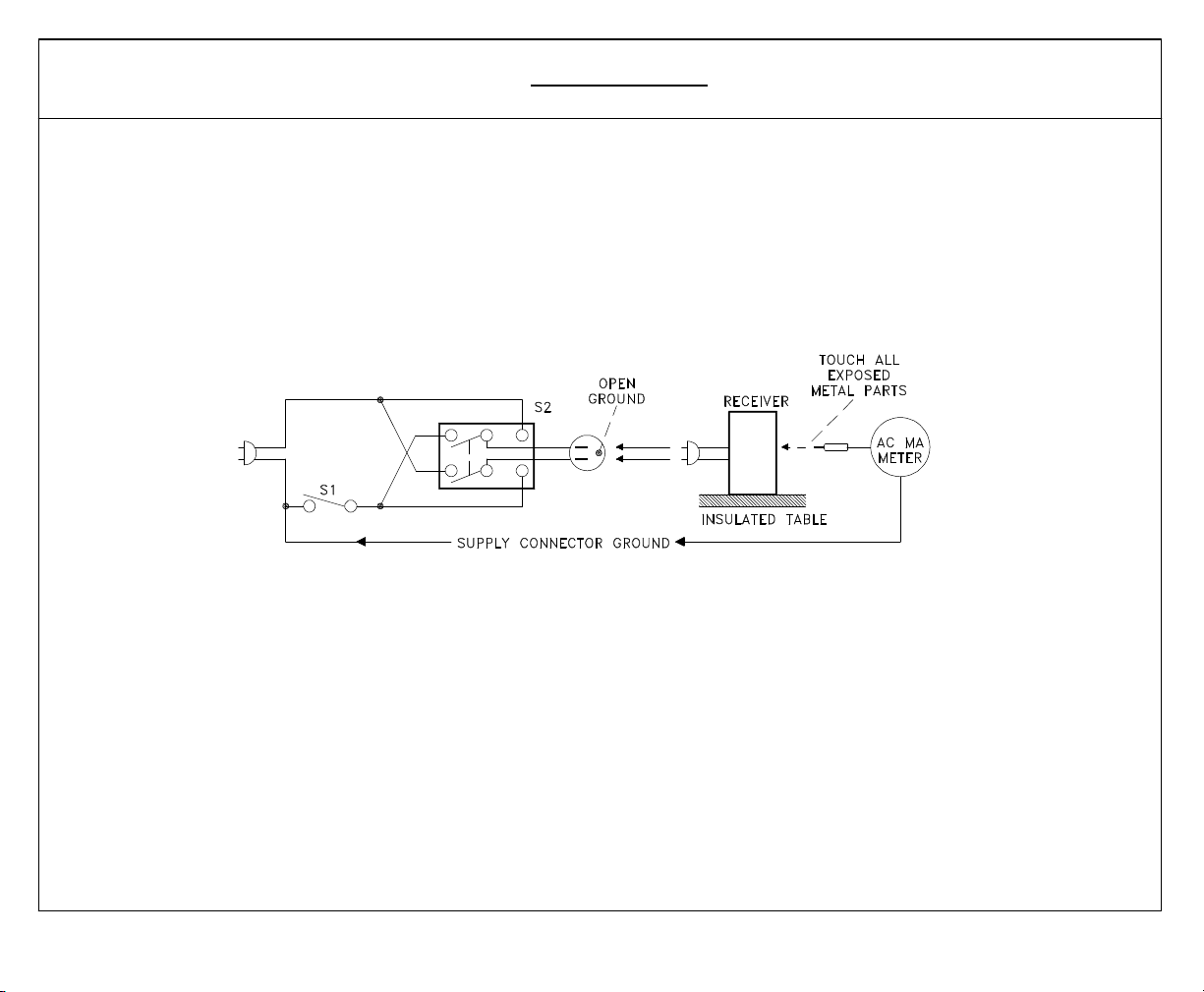
2. Hot Check ...Use the circuit shown below to perform the hot check test.
1. Keep switch S1 open and connect the receiver to the measuring circuit. Immediately after connection, and with the switching devices of
the receiver in their operating positions, measure the leakage current for both positions of switch S2.
2. Close switch S1, energizing the receiver. Immediately after closing switch S1, and with the switching devices of the receiver in their
operating positions, measure the leakage current for both positions of switch S2. Repeat the current measurements of items 1 and 2 after
the receiver has reached thermal stabilization. The leakage current must not exceed 0.5 milliampere (mA).
5
Page 8
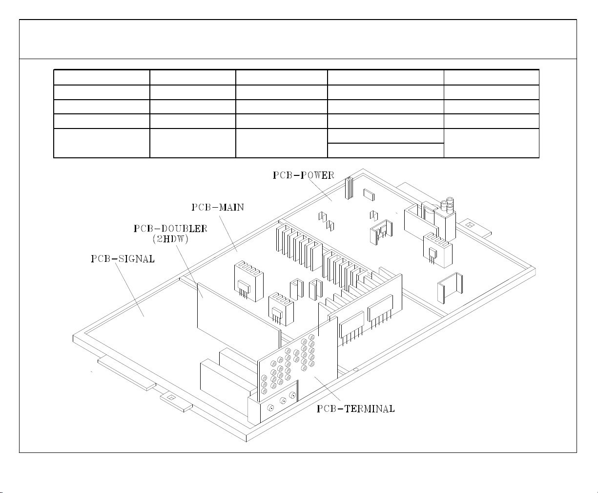
V20 Chassis - PCB Functions and Locations
PCB-Terminal PCB-Signal PCB-Doubler PCB-Main PCB-Power
A/V Inputs Control uPC PIP-POP Horizontal Defl. Power Supplies
A/V Selection Tuning Picture Format Vertical Defl. High Voltage
3D-Y/C VCJ 3:2 Pull Down Audio Amp. SVM
NTSC Video Convergence Line Double Convergence Amps.
Decoders Generator 480i to 480p DBF
6
Page 9
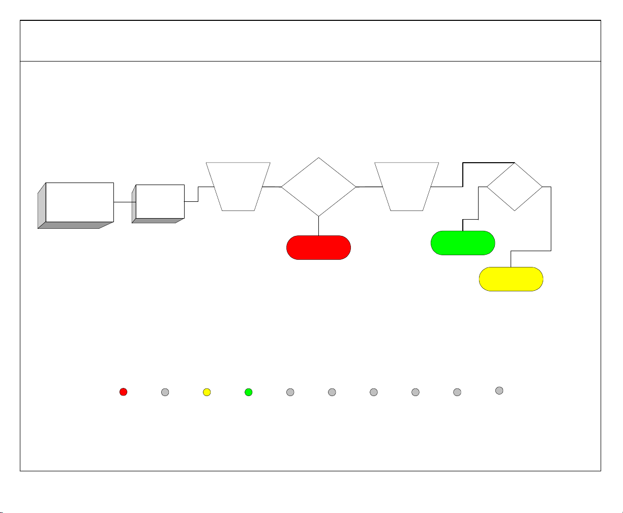
V20 Chassis - Audio Problem
Audio problem
Supply
Audio
problem any
or all NTSC
sources
Main Power Signal Terminal 2HDW 3DYC Jungle Conv-Gen DM Assembly
signal to
antenna
input.
Check Monitor
Output. Good
audio?
YES
PWB-Main
NO
Supply
signal to
different
line
inputs
NO
PWB-Terminal
Have audio
to speakers?
YES
PWB-Signal
CRT(s)
7
Page 10

No video
2HDW TEST
PWB-2HDW
YES
YES
Supply
480p signal
to
component
video input.
Component
video good?
NO
PWB-Signal
V20 Chassis - Video Problem
Video Problem - 1
Video problem
with PIP
PIP picture
Go to
2HDW
Test
NO
3DYC Test
good?
NO
YES
Compare
Main
picture to
PIP
picturet.
NO
PWB-Terminal
Main picture
good?
YES
Go to
2HDW
Test
Main Power Signal Terminal 2HDW 3DYC Jungle Conv-Gen DM Assembly
8
Page 11

V20 Chassis - Video Problem
Video Problem - 2
Video problem
all inputs
Input a
480P
signal to a
2HDW Test
Main Power Signal Terminal 2HDW 3DYC Jungle Conv-Gen DM Assembly
component
input.
PWB-2HDW
Switch screen
format
between
"Standard"
and "Narrow".
YES
Standard
format good?
NO
PWB-Signal
Both formats
YES
faulty?
NO
PWB-Signal
9
Page 12

V20 Chassis - Shut-Down Problem
Shut-Down Problem - 1
With the set OFF, Press and hold the Front Panel "Device" and "Menu" buttons for five seconds
Observe the flashing pattern of the front panel L.E.D.
Pause
Pause
Normal
Operation
X-Ray
Protect
Main Power Signal Terminal 2HDW 3DYC Jungle Conv-Gen DM Assembly
Press
POWER
Set powers up then
shuts down?
YES
Arcing at CRTs
seen or heard?
NO
PWB-Power
NO
PWB-Main
YES
CRT(s)
CRT(s)
10
Page 13

Shut-Down Problem
Shut-Down Problem - 2
With the set OFF, Press and hold the Front Panel "Device" and "Menu" buttons for five seconds
Observe the flashing pattern of the front panel L.E.D.
Pause
Pause
Main Power Signal Terminal 2HDW 3DYC Jungle Conv-Gen DM Assembly
Short-Circuit
Protect
Deflection
Disconnect 3
PWB-CRT.
Press POWER
PWB-Main
Set powers up?
YES
PWB-Signal
NO
PWB-Power
PWB-Main
CRT(s)
11
Page 14

V20 Chassis - Convergence Problem
Convergence
Main
Adjust using
charts shown at
Problem
Power Signal Terminal 2HDW 3DYC Jungle Conv-Gen DM Assembly
Convergence
Master
Convergence
problem resolved?
NO
Does picture
respond to
adjustments?
NO
PWB-Main
YES
YES
Done!
PWB-Signal
CRT(s)
12
Page 15

CONV MISC.
MENU-2-2-5-9-6
Item#
Abbrev.
Description
RangeSDHD
17
EPWP
EEPROM write protection
0~100
V20 Chassis - Convergence Master
COARSE CONV GREEN (MENU-2-2-5-9-5)
#
Abbrev.
Description
WS-55311
WS-65311
SDHDSDHDSDHDSDHDSDHDSDHDSDHDSD
HD
12
VLIN
Vert. Linearity
0000000000000000COARSE CONV RED (MENU-2-2-5-9-5)
#
Abbrev.
Description
WS-55311
WS-65311
SDHDSDHDSDHDSDHDSDHDSDHDSDHDSD
HD
11
SDBW
Side Bow
00003030303000303030303030COARSE CONV BLUE (MENU-2-2-5-9-5)
#
Abbrev.
Description
WS-55311
WS-65311
SDHDSDHDSDHDSDHDSDHDSDHDSDHDSD
HD
Data
1 HVOL HV Adjust 0~352 150 150
2 VCNT V-saw amplitude 0~127 29 29
3 VSTR V-saw start timee 0~127 0 10
4 VOFS V-saw offset 0~127 10 8
5 STLN Start line 0~127 38 26
6 FPHS Fine phase 0~352 296 288
7 CPHS Coarse phase 0~31 15 15
8 HOFS H-saw offset 0~127 22 22
9 DPHS DF coarse horiz phase 0~31 1 1
10 DOFS DF offset 0~127 34 34
11 TPHS Test Pattern phase 0~352 39 31
12 TPVD Test Pattern Vert. Position 0~127 22 39
13 ODEV Odd/Even detection 0~352 200 125
14 HRTC H-saw retrace 0~3 1 1
15 DRTC DF retrace 0~3 1 1
16 DAC External DAC selection 0~1 1 1
VS-50111 WS-65411 WS-73411
1 HSTA Horiz. Position 0 0 0 0 0 0 0 0 0 0 0 0 0 0 0 0
2 VSTA Vert. Position 0 0 0 0 0 0 0 0 0 0 0 0 0 0 0 0
3 SKEW Skew (Y axis) 0 0 0 0 0 0 0 0 0 0 0 0 0 0 0 0
4 TILT Tilt (X axis) 5 0 0 0 0 0 0 0 0 0 0 0 0 0 0 0
5 HWID Width 0 10 5 5 20 20 0 0 5 5 0 0 0 0 0 0
6 HLIN Horiz. Linearity 0 0 15 15 0 0 10 10 15 15 10 10 10 10 10 10
7 SPCC Side PC Corr. 0 0 0 0 0 0 0 0 0 0 0 0 0 0 0 0
8 HKEY Horiz. Keystone 0 17 0 0 0 17 10 10 0 0 0 0 0 0 0 0
9 TBPC Top/Bottom PC -200 -169 -150 -150 -180 -190 -200 -190 -150 -150 -200 -170 -200 -170 -200 -180
10 VKEY Vert. Keystone 0 14 0 20 0 10 15 10 0 20 15 10 15 10 15 10
11 VWID Height 11 17 40 30 20 30 30 30 40 30 30 30 30 30 30 30
WS-55411
VS-60111WS-48311
WS-48311 VS-50111 WS-55411 VS-60111 WS-65411 WS-73411
1 HSTA Horiz. Position 50 50 50 50 50 50 50 50 50 50 50 50 50 50 50 50
2 VSTA Vert. Position 0 0 0 0 0 0 0 0 0 0 0 0 0 0 0 0
3 SKEW Skew (Y axis) 0 0 0 0 0 0 0 0 0 0 0 0 0 0 0 0
4 TILT Tilt (X axis) 0 0 0 0 0 0 0 0 0 0 0 0 0 0 0 0
5 HLIN Horiz. Linearity -195 -170 -140 -125 -150 -170 -180 -170 -140 -125 -150 -150 -150 -150 -220 -190
6 HWID Width 22 30 5 0 0 0 0 0 5 0 0 0 0 0 0 0
7 VKEY Vert. Keystone -100 -85 15 -87 -70 -90 -100 -95 15 -87 -90 -70 -90 -70 -100 -110
8 VWID Height 0 16 0 0 0 0 0 0 0 0 0 0 0 0 0 0
9 VLIN Vert. Linearity 0 0 0 0 20 20 0 0 0 0 0 0 0 0 0 0
10 TBPC Top/Bottom PC -200 -169 -150 -150 20 20 20 20 -150 -150 20 20 20 20 20 20
WS-65411 WS-73411WS-48311 VS-50111 WS-55411 VS-60111
1 HSTA Horiz. Position -50 -50 -50 -50 -50 -50 -50 -50 -50 -50 -50 -50 -50 -50 -50 -50
2 VSTA Vert. Position 0 0 0 0 0 0 0 0 0 0 0 0 0 0 0 0
3 SKEW Skew (Y axis) 0 0 0 10 0 0 0 0 0 10 0 0 0 0 0 0
4 TILT Tilt (X axis) 0 0 0 0 0 0 0 0 0 0 0 0 0 0 0 0
5 HLIN Horiz. Linearity 190 165 150 160 160 175 175 170 150 160 160 150 160 150 230 200
6 HWID Width -14 -25 -20 -30 0 0 0 0 -20 -30 0 0 0 0 0 0
7 VKEY Vert. Keystone 100 90 75 75 75 80 70 75 75 75 90 65 90 65 80 90
8 VWID Height 0 0 -20 -20 0 0 0 0 -20 -20 0 0 0 0 0 0
9 VLIN Vert. Linearity 0 0 0 0 0 0 0 0 0 0 0 0 0 0 0 0
10 TBPC Top/Bottom PC 0 0 0 0 0 20 0 0 0 0 0 0 0 0 0 0
11 SDBW Side Bow 0 0 0 0 -30 -30 -30 -30 0 0 -30 -30 -30 -30 -30 -30
13
Page 16

V20 - Parts List
[#] Model Legend:
(1) VS-50111, (2) VS-60111, (3) WS-48311, (4) WS-55311, (5) WS-55411, (6) WS-65311, (7) WS-65411, (8) WS-73411, (9) VS-A50, (10) WS-A48,
(11) WS-A55, (12) WS-A65
Part # Part Name & Description Reff[#]
TUBES
251C215010 ASSY-CRT-RED 1
251C215020 ASSY-CRT-GREEN 1
251C215030 ASSY-CRT-BLUE 1
251C215040 ASSY-CRT-RED 2
251C215050 ASSY-CRT-GREEN 2
251C215060 ASSY-CRT-BLUE 2
251C216010 ASSY-CRT-RED 3
251C216020 ASSY-CRT-GREEN 3
251C216030 ASSY-CRT-BLUE 3
251C216040 ASSY-CRT-RED 4
251C216050 ASSY-CRT-GREEN 4
251C216060 ASSY-CRT-BLUE 4
251C216070 ASSY-CRT-RED 5
251C216080 ASSY-CRT-GREEN 5
251C216090 ASSY-CRT-BLUE 5
251C217010 ASSY-CRT-RED 6
251C217020 ASSY-CRT-GREEN 6
251C217030 ASSY-CRT-BLUE 6
251C217040 ASSY-CRT-RED 7
251C217050 ASSY-CRT-GREEN 7
251C217060 ASSY-CRT-BLUE 7
251C217070 ASSY-CRT-RED 8
251C217080 ASSY-CRT-GREEN 8
251C217090 ASSY-CRT-BLUE 8
251C215070 ASSY-CRT-RED 9
251C215080 ASSY-CRT-GREEN 9
251C215090 ASSY-CRT-BLUE 9
251C218070 ASSY-CRT-RED 10
251C218080 ASSY-CRT-GREEN 10
Part # Part Name & Description Reff[#]
251C218090 ASSY-CRT-BLUE 10
251C218010 ASSY-CRT-RED 11
251C218020 ASSY-CRT-GREEN 11
251C218030 ASSY-CRT-BLUE 11
251C218040 ASSY-CRT-RED 12
251C218050 ASSY-CRT-GREEN 12
251C218060 ASSY-CRT-BLUE 12
PRINTED CIRCUIT BOARDS
930B884001 ASSY-PWB-SIGNAL 3,4,6
930B884002 ASSY-PWB-SIGNAL 5,7
930B884003 ASSY-PWB-SIGNAL 1,2
930B884004 ASSY-PWB-SIGNAL 8
930B884006 ASSY-PWB-SIGNAL 9
930B884005 ASSY-PWB-SIGNAL 10,11,12
930B885001 ASSY-PWB-MAIN 3,4,5,10,11
930B885002 ASSY-PWB-MAIN 6,7,12
930B885003 ASSY-PWB-MAIN 1,2,9
930B885004 ASSY-PWB-MAIN 8
930B886001 ASSY-PWB-POWER 3,4,5,6,7,10,11,12
930B886002 ASSY-PWB-POWER 1,2,9
930B886003 ASSY-PWB-POWER 8
930B887001 ASSY-PWB-TERMINAL 3,4,5,6,7,10,11,12
930B887002 ASSY-PWB-TERMINAL 1,2,9
935C995001 ASSY-PWB-CRT
935C996001 ASSY-PWB-DOUBLER
935D619001 ASSY-PWB-PREAMP 1,2,3,4,6,9,10,11,12
935D619002 ASSY-PWB-PREAMP 5,7,8
935D620001 ASSY-PWB-FRONT
935D621001 ASSY-PWB-CONTROL
14
Page 17

V21 Chassis - PCB Functions and Locations
Convergence
NTSC Video
Tuning
Picture Format
Generator
Line Double
PCB-Terminal PCB-3DYC PCB-Signal PCB-2HDW PCB-Conv
A/V Inputs 3D-Y/C Control uPC PIP-POP
A/V Selection
Decoders VCJ 3:2 Pull Down
480i to 480p
PCB-Power PCB-Main PCB-Jungle PCB-DBF
Power Supplies Vertical Defl. Vert Drive Dyn. Focus
Audio Amp. Horizontal Defl. Horiz. Drive
Conv. Amps High Voltage
15
Page 18

V21 Chassis - Audio Problem
Audio problem
Supply
Audio
problem any
or all NTSC
sources
Main Power Signal Terminal 2HDW 3DYC Jungle Conv-Gen DM Assembly
signal to
antenna
input.
Check Monitor
Output. Good
audio?
YES
PWB-Main
NO
Supply
signal to
different
line
inputs
NO
PWB-Terminal
Have audio
to speakers?
YES
PWB-Signal
16
Page 19

No video
YES
V21 Chassis - Video Problem
Video Problem - 1
Video problem
with PIP
3DYC Test
Compare
Main
picture to
picturet.
NO
PIP
Main picture
good?
YES
PCB-2HDW
Supply
signal to
DTV
input.
Go to
2HDW
YES
DTV video
good?
NO
DM Assembly
Main Power Signal Terminal 2HDW 3DYC Jungle Conv-Gen DM Assembly
Test
PIP picture
good?
YES
PCB-3DYC
NO
17
Go to
2HDW
Test
Page 20

V21 Chassis - Video Problem
Video Problem - 2
Video problem
all inputs
Input a
480P
signal to a
2HDW Test
Main Power Signal Terminal 2HDW 3DYC Jungle Conv-Gen DM Assembly
component
input.
PWB-2HDW
Switch screen
format
between
"Standard"
and "Narrow".
YES
Standard
format good?
NO
PWB-Signal
Both formats
faulty?
NO
PWB-Signal
YES
YES
Supply
signal to
DTV
input.
DTV video
good?
NO
DM Assembly
18
Page 21

V21 Chassis - Shut-Down Problem
Shut-Down Problem - 1
With the set OFF, Press and hold the Front Panel "Device" and "Menu" buttons for five seconds
Observe the flashing pattern of the front panel L.E.D.
Pause
Pause
Normal
Operation
X-Ray
Protect
Main Power Signal Terminal 2HDW 3DYC Jungle Conv-Gen DM Assembly
Set powers up then
shuts down?
Press
POWER
PWB-Power
Set powers up then
shuts down?
YES
Arcing at CRTs
seen or heard?
NO
PWB-Main
NO
PWB-Main
YES
CRT(s)
CRT(s)
19
Page 22

V21 Chassis - Shut-Down Problem
Shut-Down Problem - 2
With the set OFF, Press and hold the Front Panel "Device" and "Menu" buttons for five seconds
Observe the flashing pattern of the front panel L.E.D.
Pause
Pause
Short-Circuit
Protect
Horizontal
Deflection
Continuous
flashing
Main Power Signal Terminal 2HDW 3DYC Jungle Conv-Gen DM Assembly
Disconnect 3
PWB-CRT.
Press POWER
PWB-Main
Unplug set.
Wait 30 seconds.
Plug set in.
Press Power.
Set powers up? PWB-Main
PWB-Power
YES
Set powers up?
YES
NO
DM Restored!
NO
PWB-Signal
DM Assembly
CRT(s)
20
Page 23

V21 Chassis - Convergence Problem
Main
Adjust using
Convergence
Problem
Power Signal Terminal 2HDW 3DYC Jungle Conv-Gen DM Assembly
charts shown at
Convergence
Master
Convergence
problem resolved?
NO
Does picture
respond to
adjustments?
NO
PWB-Power
YES
YES
Done!
PWB-Conv-Gen
CRT(s)
21
Page 24

V21 Chassis - Convergence Master
Item
Abbrev.
Data
Notes
Number
NameSDHD
CONV GREEN Items
NameSDHDSDHDSDHDSDHD
*HSTA and VSTA must not exceed ±200
CONV RED Items
NameSDHDSDHDSDHDSDHD
11
SDBW
Horizontal Side Bow
3030303030305030*HSTA and VSTA must not exceed ±200
CONV BLUE Items
NameSDHDSDHDSDHDSDHD
10
TPPC
Top/Bottom PC Correction
0
-20000-20
-20
0
11
HSBW
Horizontal Side Bow
-30
-30
-30
-30
-30
-30
-30
-30
*HSTA and VSTA must not exceed ±200
CONV MISC
1 HVOL HV Adj.
2 VCNT 29 29 Preset
3 VSTR 0 0 "
4 VOFS 25 0 "
5 STLN 45 34 "
6 FPHS 288 288 "
7 CPHS 15 15 "
8 HOFS 22 22 "
9 DPHS 0 0 "
10 DOFS 51 51 "
11 TPHS 34 36 "
12 TPVD 25 39 "
13 ODEV 200 125 "
14 HRTC 1 1 "
15 DRTC 1 1 "
16 DAC 1 1 "
17 EPWP 0 0 "
18 SCRL 25 25 "
19 SDEL 600 600 "
20 FDEL 3 3 "
* Do not change "1 HVOL" if it has been
previously set.
(MENU-2-1-5-9-6)
160
(MENU-2-1-5-9-5)
No. Abbrev. Description
1 HSTA* Horizontal Position 0 0 0 0 0 0 0 0
2 VSTA* Vertical Position -15 0 -15 0 -15 0 -20 0
3 SKEW Skew (Y axis rotation) 0 0 0 0 0 0 0 0
4 TILT Tilt (X axis rotation) 0 0 0 0 0 0 0 0
5 HWID Horisontal Width 30 30 30 30 30 30 20 20
6 HLIN Horizontal Linearity 0 0 -15 -10 -10 -20 -10 -10
7 SPCC Side Pin Cushion Correction 0 0 0 0 0 0 0 0
8 HKEY Horizontal Keystone 0 0 0 0 0 0 0 0
9 TBPC Top/Bottom PC Correction -150 -150 -200 -190 -200 -170 -220 -180
10 VKEY Vertical Keystone 15 10 15 10 0 0 10 10
11 VWID Vertical Height 0 0 0 0 0 0 0 0
12 VLIN Vertical Linearity. 0 0 0 0 0 0 0 0
No. Abbrev. Description
1 HSTA Horizontal Position 50 50 50 50 50 50 50 50
2 VSTA Vertical Position 0 0 0 0 0 0 0 0
3 SKEW Skew (Y axis rotation) 0 0 0 0 0 0 0 0
4 TILT Tilt (X axix rotation) 0 0 0 0 0 0 0 0
5 HLIN Horixontal Linearity -190 -190 -180 -170 -150 -150 -220 -190
6 HWID Horizontal Width 0 -10 0 0 10 10 10 10
7 VKEY Vertical Keystone Correction -120 -110 -100 -95 -90 -70 -100 -110
8 VWID Vertical Height 0 0 0 0 0 0 0 0
9 VLIN Vertical Linearity 0 0 0 0 0 0 0 0
10 TPPC Top/Bottom PC Correction 20 20 20 20 20 20 20 20
No. Abbrev. Description
1 HSTA Horizontal Position -50 -50 -50 -50 -50 -50 -50 -50
2 VSTA Vertical Position 0 0 0 0 0 0 0 0
3 SKEW Skew (Y axis rotation) 0 0 0 0 0 0 0 0
4 TILT Tilt (X axix rotation) 0 0 0 0 0 0 0 0
5 HLIN Horixontal Linearity 200 190 175 170 160 150 230 200
6 HWID Horizontal Width 0 -30 0 -10 0 -10 -20 -20
7 VKEY Vertical Keystone Correction 130 80 90 65 70 75 80 90
8 VWID Vertical Height 0 0 0 0 0 0 0 0
9 VLIN Vertical Linearity 0 0 0 0 0 0 0 0
48" Data
48" Data 73" Data
55" Data 65" Data
55" Data 65" Data
65" Data55" Data
73" Data48" Data
(MENU-2-1-5-9-5)
73" Data
(MENU-2-1-5-9-5)
22
Page 25

V21 - Parts List
[#] Model Legend:
(1) WS-B55, (2) WS-48511, (3) WS-55511, (4) WS-55711, (5) WS-65511, (6) WS-65611, (7) WS-65711, (8) WS-65712, (9) WS-73711
Part # Part Name & Description [#]
TUBES
251C219040 ASSY-CRT-RED 3
251C219050 ASSY-CRT-GREEN 3
251C219060 ASSY-CRT-BLUE 3
251C219070 ASSY-CRT-RED 4
251C219080 ASSY-CRT-GREEN 4
251C219090 ASSY-CRT-BLUE 4
251C220010 ASSY-CRT-RED 5
251C220020 ASSY-CRT-GREEN 5
251C220030 ASSY-CRT-BLUE 5
251C220040 ASSY-CRT-RED 6
251C220050 ASSY-CRT-GREEN 6
251C220060 ASSY-CRT-BLUE 6
251C220070 ASSY-CRT-RED 7
251C220080 ASSY-CRT-GREEN 7
251C220090 ASSY-CRT-BLUE 7
251C221010 ASSY-CRT-RED 8
251C221020 ASSY-CRT-GREEN 8
251C221030 ASSY-CRT-BLUE 8
251C221040 ASSY-CRT-RED 9
251C221050 ASSY-CRT-GREEN 9
251C221060 ASSY-CRT-BLUE 9
251C221070 ASSY-CRT-RED 1
251C221080 ASSY-CRT-GREEN 1
251C221090 ASSY-CRT-BLUE 1
251C222010 ASSY-CRT-RED 2
251C222020 ASSY-CRT-GREEN 2
251C222030 ASSY-CRT-BLUE 2
Part # Part Name & Description [#]
PRINTED CIRCUIT BOARDS
930B866012 ASSY-PWB-MAIN 8746513
930B866013 ASSY-PWB-MAIN 9
930B866014 ASSY-PWB-MAIN 2
930B879002 ASSY-PWB-POWER
930B880003 ASSY-PWB-SIGNAL 12356
930B880004 ASSY-PWB-SIGNAL 4789
955C230002 ASSY-DM
935C965003 ASSY-PWB-CRT
935C966002 ASSY-PWB-2HDW
935C967001 ASSY-PWB-TERMINAL 12356
935C967002 ASSY-PWB-TERMINAL 4789
935D521006 ASSY-PWB-DBF
935D581002 ASSY-PWB-PREAMP
935D583001 ASSY-PWB-JUNGLE 1
935D583002 ASSY-PWB-JUNGLE
935D584002 ASSY-PWB-SVM
935D585001 ASSY-PWB-CONV-GEN
935D586001 ASSY-PWB-3DYC/MD
935D587002 ASSY-PWB-CONTROL 2
935D588003 ASSY-PWB-FRONT 12356
935D588004 ASSY-PWB-FRONT 4789
935D605002 ASSY-PWB-CROSS OVER 4789
23
Page 26

24
Page 27

Page 28

 Loading...