

Page 1
LEVEL 3 SERVICE
FA9M0476
COSMO (DUAL BAND)
R V A : Création D.JUET 04/00 Rédigé par Verifié par Approuvé par
E E
V R
I S
S I
I O
O N
N S
S
Mitsubishi Electric Telecom Europe S.A. Version A
ZA le Piquet, 35370 Etrelles Date: 04/00
Phone: +33 2 99 75 71 00
Fax: +33 2 99 75 71 47
Written by Checked by Approuved by
D.JUET BT.LEGORGEU G. LEBASTARD
Page 2

Page 3
Level 3 Service Manual
COSMO
TABLE OF CONTENTS
1. FUNCTIONAL DESCRIPTION ............................................................................................................1
1.A BLOCK DIAGRAM ...............................................................................................................................1
1.B DESCRIPTION OF BLOCK DIAGRAM......................................................................................................1
1.b.1 IC 300 One-C (vWS22100). ....................................................................................................... 1
1.b.2 IC100 IPD (Rohm BH6070KUT)................................................................................................ 1
1.b.3 IC600 RF-IC (Hitachi HD155121FEB). .................................................................................... 1
1.b.4 IC601 PLLs & VCOs.................................................................................................................. 1
1.b.5 Memory system..........................................................................................................................1
1.b.6 System Clock. ............................................................................................................................ 2
2. BATTERY MANAGEMENT.................................................................................................................2
2.A BLOCK DIAGRAM ............................................................................................................................... 2
2.B DESCRIPTION. .................................................................................................................................... 2
2.C CHARGING PROCESS. .......................................................................................................................... 3
2.D MAIN CHARACTERISTICS..................................................................................................................... 4
2.E AUTONOMY CONTROL........................................................................................................................ 4
2.F POWER ON. ........................................................................................................................................ 5
2.f.1 POWER-Key is pressed (see a ):................................................................................................... 5
2.f.2 TESTPS is connected (see b): ........................................................................................................ 5
2.f.3 An EXPS accessory is connected (see c):....................................................................................... 5
2.f.4 RTC alarm interrupt:..................................................................................................................... 5
2.G POWER OFF........................................................................................................................................ 7
2.H REAL TIME CLOCK ............................................................................................................................. 7
3. RF SECTION..........................................................................................................................................8
3.A FREQUENCY RANGE............................................................................................................................ 8
3.a.1 E-GSM Frequency :....................................................................................................................... 8
3.a.2 DCS Frequency : ........................................................................................................................... 8
3.B SYNTHESISER CIRCUIT DESCRIPTION................................................................................................. 10
3.C RF BLOCK DIAGRAM....................................................................................................................... 11
3.c.1 Reception Block Diagram. ........................................................................................................... 12
3.c.2 Transmission Block Diagram. ...................................................................................................... 13
3.c.3 Output power control................................................................................................................... 14
4. SPEECH CODER................................................................................................................................. 15
4.A FEATURES........................................................................................................................................ 15
4.B FULL RATE / HALF RATE / ENHANCED FULL RATE............................................................................... 15
5. ANALOGUE AUDIO. .......................................................................................................................... 17
5.A BUZZER. .......................................................................................................................................... 17
5.B SPEAKER (RX AUDIO)....................................................................................................................... 17
5.C MICRO (TX AUDIO).......................................................................................................................... 17
6. TESTMODE SOFTWARE ................................................................................................................... 18
6.A EQUIPMENT INSTALLATION............................................................................................................... 18
6.B SOFTWARE (MTS) INSTALLATION..................................................................................................... 19
6.b.1 Simple Setup :.......................................................................................................................... 19
6.b.2 Complete Setup : ..................................................................................................................... 19
6.C SOFTWARE (MTS) DESCRIPTION ....................................................................................................... 20
6.D ENTER IN TEST MODE:....................................................................................................................... 21
6.E POWER ADJUSTMENTS ...................................................................................................................... 22
6.F RECEIVE ADJUSTMENTS .................................................................................................................... 23
7. BASIC ADJUSTMENT. ....................................................................................................................... 26
Mitsubishi Electric Telecom Europe S.A. Version A
ZA le Piquet, 35370 Etrelles Date: 04/00
Phone: +33 2 99 75 71 00
Fax: +33 2 99 75 71 47
Page 4
Level 3 Service Manual
COSMO
7.A POWER ADJUSTMENT. ...................................................................................................................... 26
7.B RSSI CONTROL. ............................................................................................................................... 29
8. SOFTWARE VERSION ...................................................................................................................... 29
Version A Mitsubishi Electric Telecom Europe S.A.
Date: 04/00 ZA le Piquet 35370 Etrelles
Phone: +33 2 99 75 71 00
Fax: + 33 2 99 75 71 47
Page 5
Level 3 Service Manual
COSMO
1. FUNCTIONAL DESCRIPTION
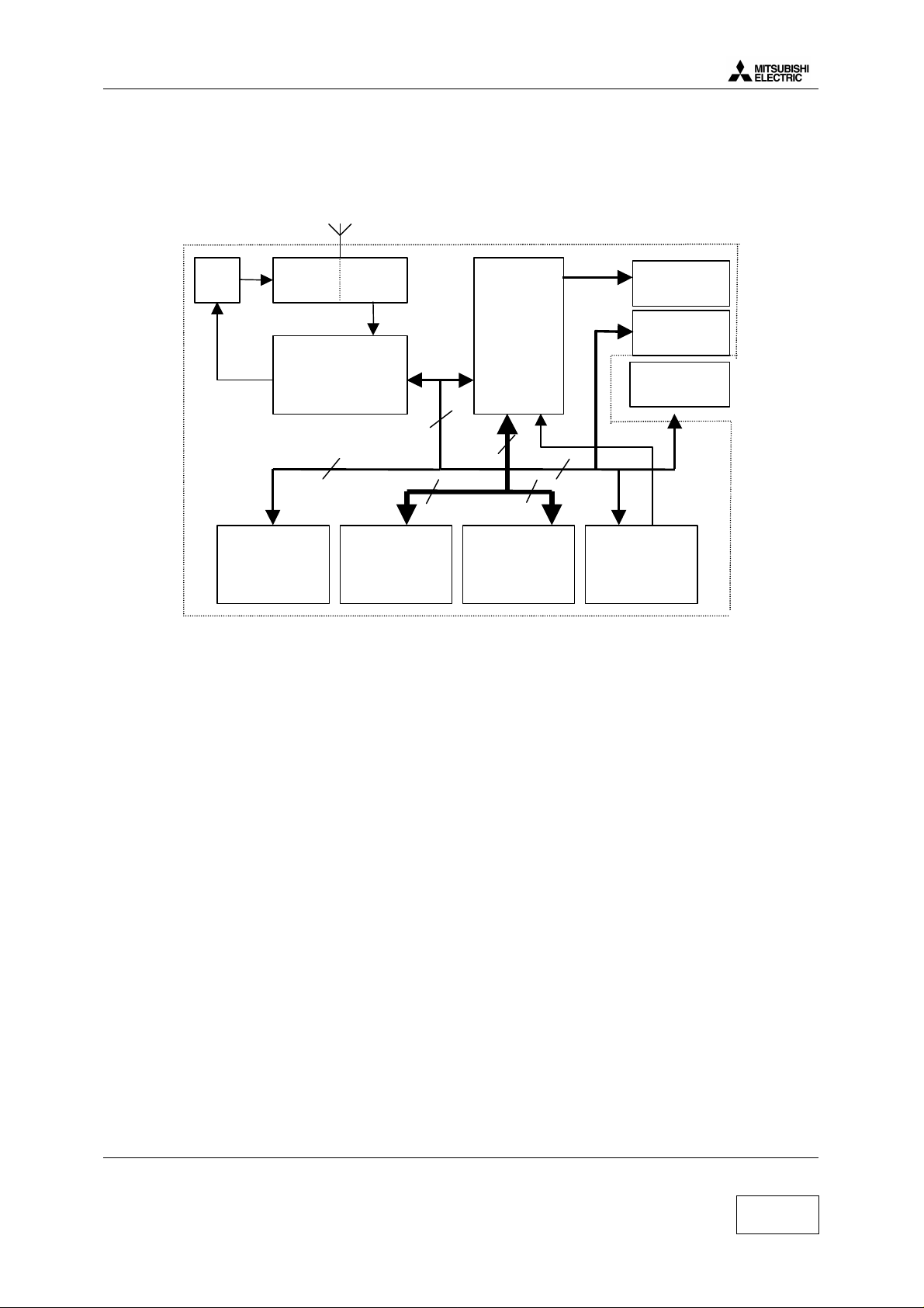
1.a Block Diagram
HPA
IC701
Serial FLASH
IC206
TX RX
SW700
RFIC
IC600
serial
LCD
FLASH
IC200
ONE-C
IC300
parallel
RAM
IC201
Row/Col
KEYBOARD
BACKLIGHT
LEDS
LCD
MODULE
reset
RFBB Board
IPD
IC100
1.b Description of Block Diagram
1.b.1 IC 300 One-C (vWS22100).
IC300 includes in one chipset Base Band part, DSP, CPU, A/D, D/A converters, TDMA frame
counters, a TX GMSK modulator, a TX power ramping circuit, RX filters. IC300 carries out the
management of the battery charging and of the audio part. It interfaces with the radio frequency part.
1.b.2 IC100 IPD (Rohm BH6070KUT).
IC100 provides the different powers supplies to RFBB board : 2.8VRTC, PSTCXO, 2.8VANA,
2.8VAUD, 2.8VD, 2.8VP, 5VSIM. It actives all L.E.D.s (red,green,LCD & keyboard) and the vibrator
inside the battery. The management of the battery charging is carried out by internal circuit of IC100.
1.b.3 IC600 RF-IC (Hitachi HD155121FEB).
Transceiver IC for E-GSM and DCS Dual Band cellular systems.
1.b.4 IC601 PLLs & VCOs
IC601 includes in one chipset 2 PLL, RF VCO and IF VCO.
1.b.5 Memory system.
IC200 : Flash ROM ( 1 M x 16 Bits ) stores the CPU program code
IC201 : RAM ( 128 k x 16 Bits ) stores data for the CPU work.
IC206 : Serial FLASH ( 2 M x 8 Bits) stores the user’s datas and hardware adjustment datas.
Mitsubishi Electric Telecom Europe S.A. Version A
ZA le Piquet, 35370 Etrelles Date: 04/00
Phone: +33 2 99 75 71 00
Fax: +33 2 99 75 71 47
1/29
Page 6
Level 3 Service Manual
Li-Ion
COSMO
1.b.6 System Clock.
The system clock for the telephone is 13 MHz TCXO, generated by X600. It is processed in IC300 to
provide serial clock for LCD, serial FLASH and IC100. The clock is buffered in IC300 One-C, and
then fed to IC100 IPD as “ CPU CLK ” . It is available on pin 56 of IC100.
During Stand-By mode, the system clock is not managed from X600 TCXO but from X300 ( “ slow
clock ” at 32.768 kHz).
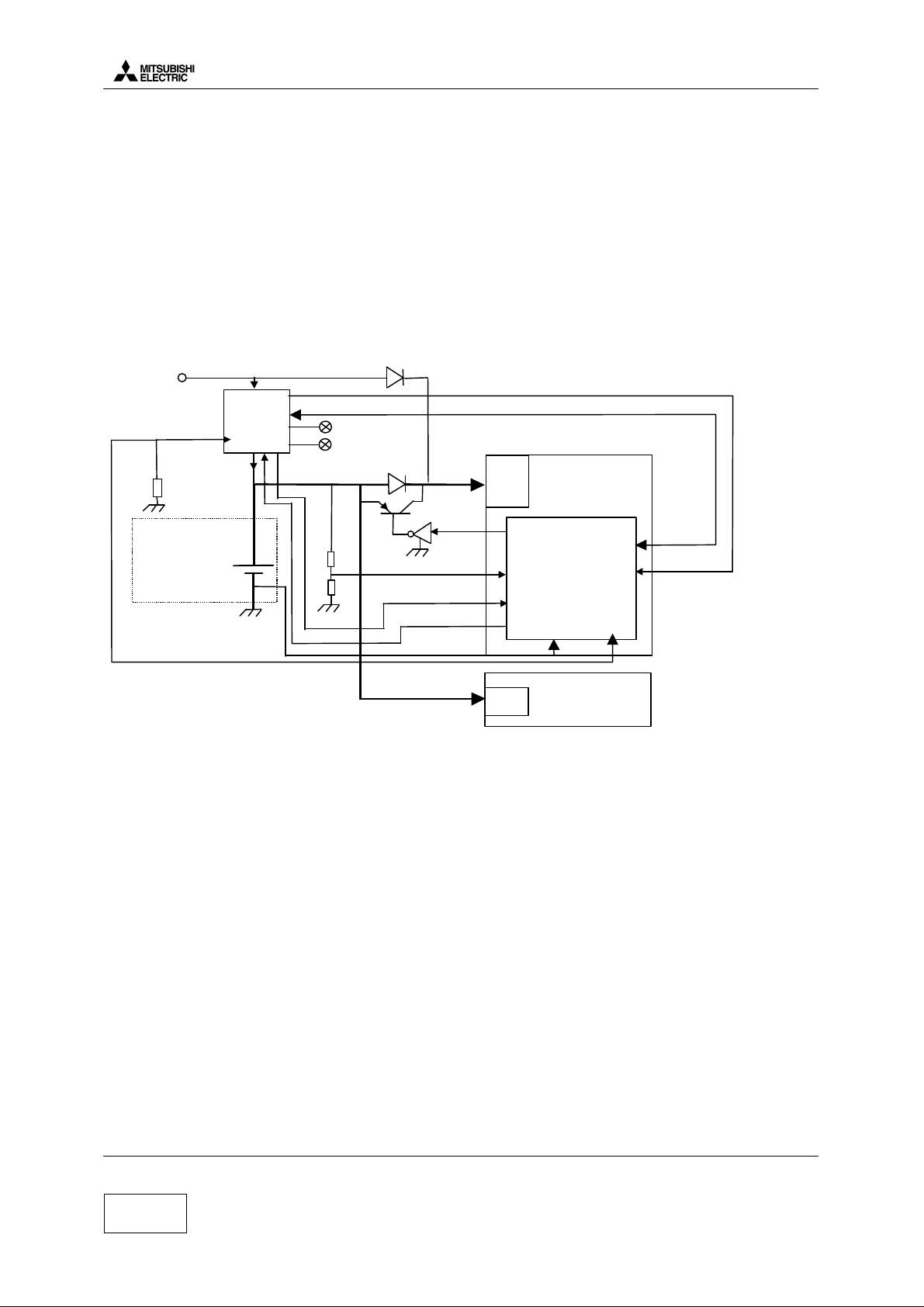
2. Battery management
2.a Block Diagram
6.5 V nominal
EXPS:
AC/DC
CLA
DTC
HF kit
TH
Thermistor
IPD
Charger
IC 100
I charge
3.7V
Green led
Red led
nominal
CHGERR
SPI interface
IPD
Regulators
IC100
Base Band
540 mAh
+
BLEV
CRLEV
BVADJ
BYPASS
BAT_SEL
TH
regulators
GPIO9
AUX_IN0
AUX_IN 2
AGC _ P
One-C
AUX_IN2
RADIO
GPIO10
Constant current :
1C : 350 mA
1/8C : 45 mA
1/20C : 17 mA
CV (adp) : 400 mA
2.b Description.
The battery is Li-Ion 540 mAh, 3.7 V nominal for Cosmo
External power supply for charging (EXPS) comes from the I/O connector at the bottom side of the
mobile (AC/DC, CLA, DTC or H/F Kit). This power supply is 6.5 V nominal. Battery presence and
battery type information are accessible in CHGM IPD register (IC100).
The battery temperature information (TH) implanted on PCB are given by threshold in IPD CHGM
register (IC100). These information is used only for charge control.
The battery level information are accessible in an A/D converter in One-C. It is also available in
CHGM IPD register (IC100), these information are given by range only for range control.
By checking CHG IPD register (IC100) , we know if EXPS is present. As described in the drawing
above, the power supply for Base Band (IC300) comes from EXPS. When EXPS is present because
EXPS level (6.5 V/ 400 mA) is always greater than battery voltage. Power supply for the radio always
comes from the battery.
The serial diode between battery and One-C (IC300) can be bypassed by software to reduce voltage
headroom. Bypass is Activated when battery is less than 3.45 V.
Version A Mitsubishi Electric Telecom Europe S.A.
Date: 04/00 ZA le Piquet 35370 Etrelles
Phone: +33 2 99 75 71 00
2/29
Fax: + 33 2 99 75 71 47
Page 7
Level 3 Service Manual
Rapid charge
COSMO
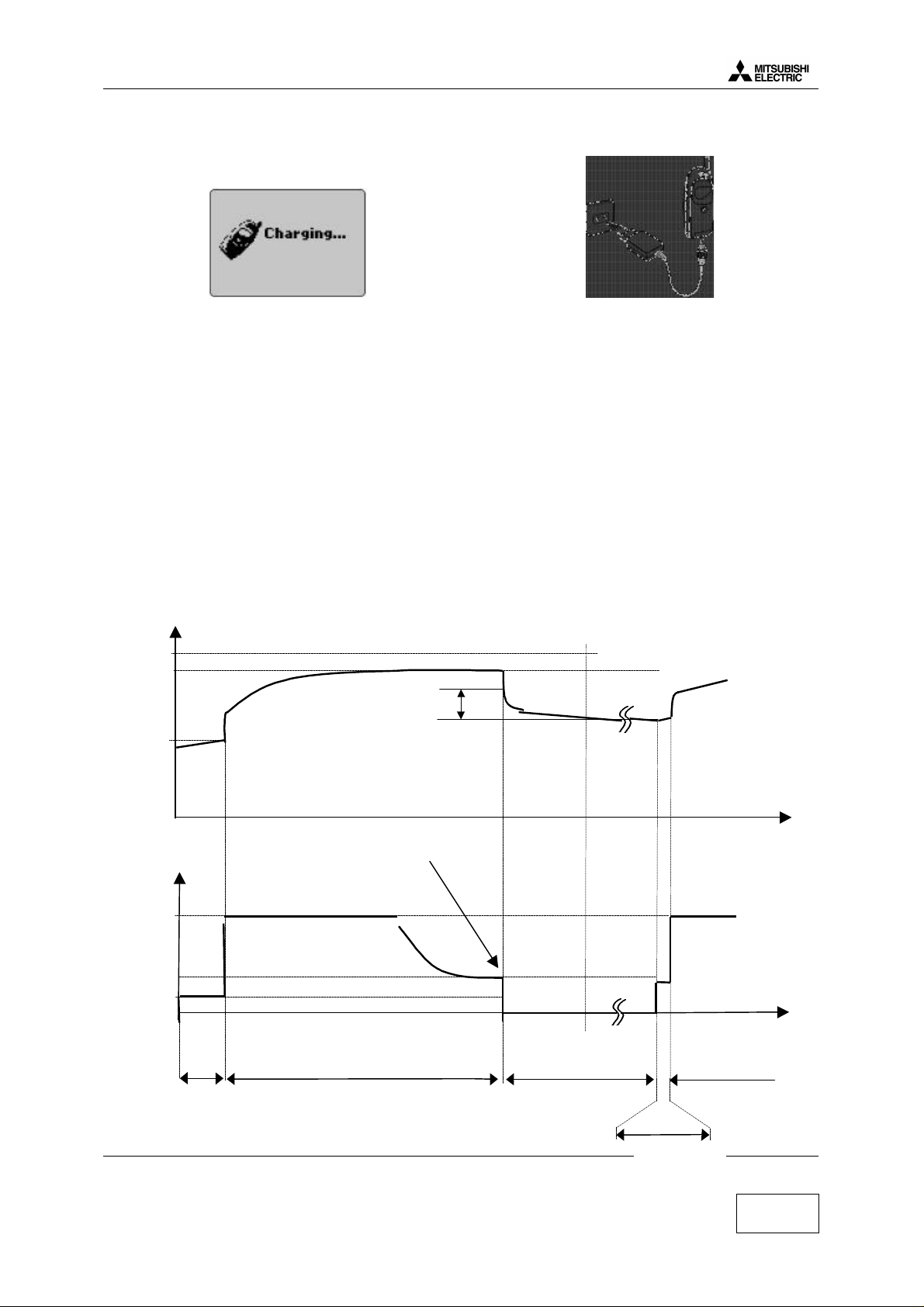
2.c Charging process.
Charging process follows these successive phases :
Pre charge:
This phase is mandatory before the rapid charge to verify that battery operation is normal (normal
battery voltage and temperature). Charge current during this phase is 45 mA (1/8 C). If the battery
voltage is less than 3.3 V the S/W starts. IPD charger in rapid charge but only if the ambient
temperature is not between 0°C and 55°C.
Rapid charge:
Charge current during this phase is 350 mA. If battery temperature becomes abnormal IPD charger
change to a low current charge 17 mA (1/20 C), while temperature comes back normal (between 0°C
and +55°C) during 15mn. Full charge detection ends Rapid charge. Full charge is detected by S/W
when charge current falls below than 50mA (full charge convergence current)
Full charge
This phase shows that the battery is fully charged by LED Green or LCD Full charge is automatically
stopped after 24 hours duration.
U battery
4.35 V Limit
4.2 V
Restart =Full charge voltage – 0.3 V
3.3 V min
Time
I charge
350 mA
51 mA
45 mA
Full charge convergence current
Time
Timer limit
(240 mn)
Precharge
Rapid
charge
Mitsubishi Electric Telecom Europe S.A. Version A
Full charge
Pre-charge
ZA le Piquet, 35370 Etrelles Date: 04/00
Phone: +33 2 99 75 71 00
Fax: + 33 2 99 75 71 47
3/29
Page 8
Level 3 Service Manual
100%
0%
COSMO
2.d Main characteristics.
The phone transmits only if the battery is attached to it, in any configuration of power supply. When
the phone is connected to H/F adapter, DTC, AC/DC, or CLA, the battery charging circuit operates.
Battery voltage (+3.7 V) is applied via TR103 or from TESTPS ( J103 pin3 ) through D124 when
using Hand Free. The main power supply is fed to the phone either from the attached battery via :
• The connector J101, or from accessories :
• H/F adapter,
• Desk Top Charger DTC,
• AC/DC adapter and CLA via the external connector J103.
R120 and R121 give an internal voltage reference Blev =(R121/R121+R120)*(Vbat-Vce). If the
battery voltage VBAT falls, then BYPASS short out the TR103 to reduce voltage drop.
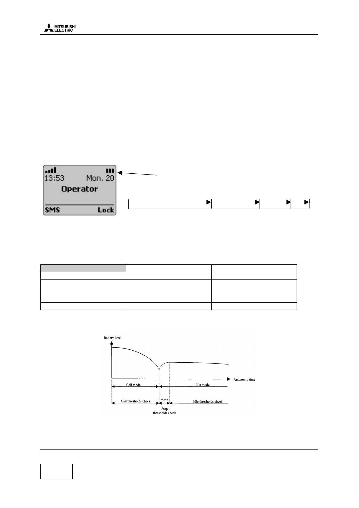
2.e Autonomy Control.
The battery energy is displayed on the LCD by 3 bars . Voltage thresholds for each bar are calculated
to have the autonomy time shared out:
battery icon
1 bar
97%
0 bar
40%
3 bars
Sharing this time by 3 equals wide -is not possible because of the very stable battery voltage level
between 20 % to 50 % autonomy time. In addition with these bars, a ”low battery alarm” is displayed
when blinks 3 bars empty.
All these thresholds are programmed in Serial FLASH by the factory and given in following thresholds
table.
Idle Mode Call Mode
Initial thresholds Battery level Battery level
3 bars → 2 bars
2 bars → 1 bars
1 bar → 0 bar
Power off 3.35 V 3.20 V
Thresholds are different according to the mode, Idle mode or Call mode. Idle mode threshold are
checked by software 25 min after the end of the call.
3.85 V 3.75 V
3.70 V 3.60 V
3.45 V 3.30 V
2 bars
80%
When battery voltage is less than 3.35 V (BAT_EMPTY level saved in serial flash is true).
The mobile is then powered off by BBPWR fall edge
Version A Mitsubishi Electric Telecom Europe S.A.
Date: 04/00 ZA le Piquet 35370 Etrelles
4/29
Phone: +33 2 99 75 71 00
Fax: + 33 2 99 75 71 47
Page 9
Level 3 Service Manual
One-C
2.8VD
RTCVCC
EN
Reg8
Power supply
COSMO
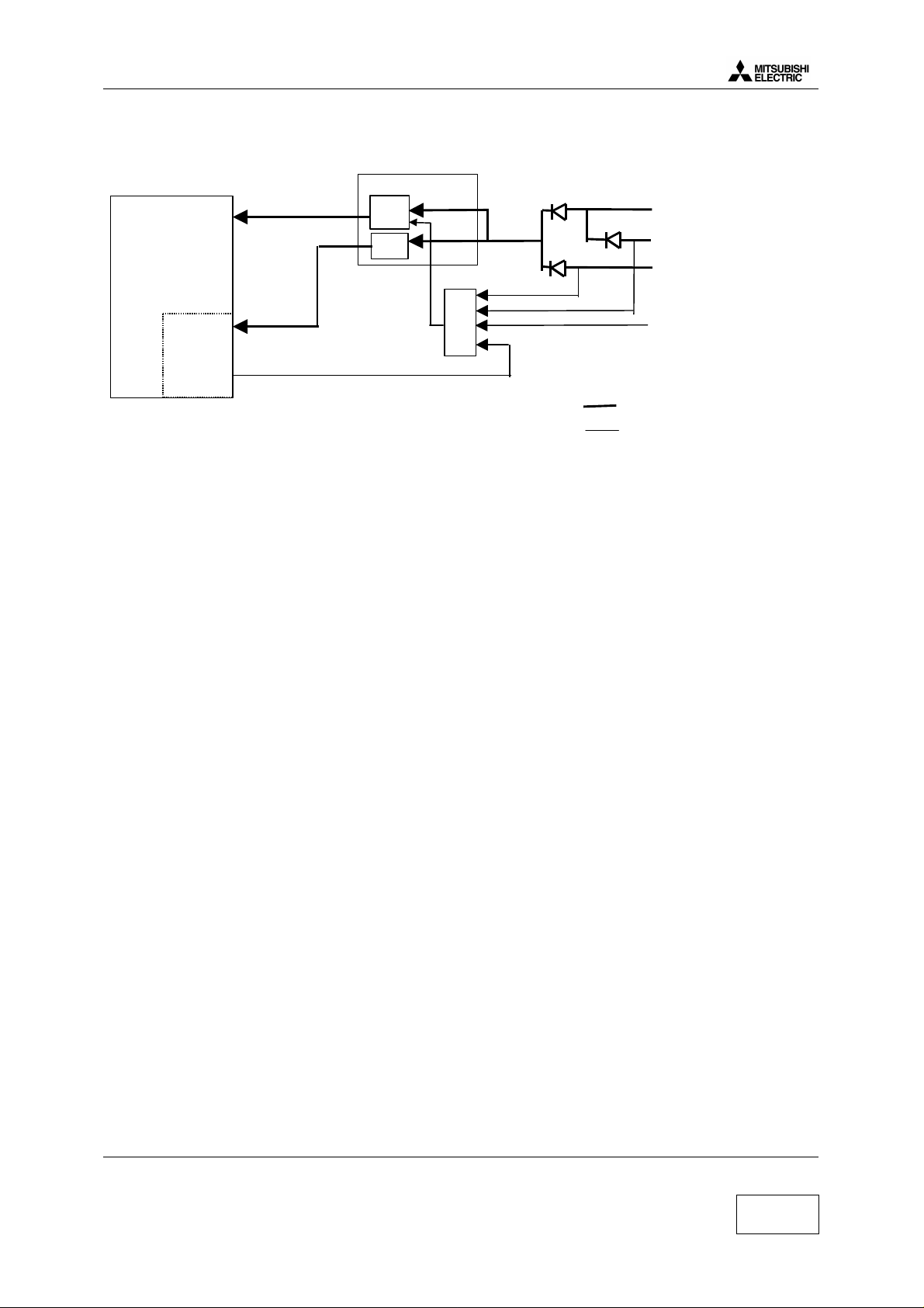
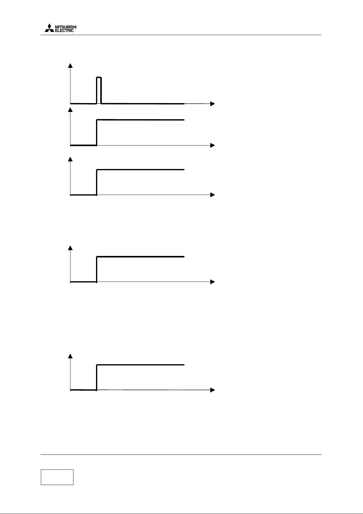
2.f Power on.
The mobile can be powered on within 4 different events:
IPD
Reg4
Battery
TESTPS
IC300
EXPS
OR
RTC
BBPWR
2.f.1 POWER-Key is pressed (see a ):
One-C power supply (2.8VD) is switched on.
SW checks if POWER-key (Row[0],Col[2]) is still pressed about 500 ms later.
Then SW activates BBPWR output to maintain One-C power supply, POWER-Key can be then
released.
SW starts the appropriate boot.(power on)
2.f.2 TESTPS is connected (see b):
One-C power supply (2.8VD) is switched on.
SW activates BBPWR output to maintain One-C power supply even if TESTPS is removed.
SW starts the appropriate boot. (“Mitsubishi M4 test mode” displayed)
2.f.3 An EXPS accessory is connected (see c):
One-C power supply (2.8VD) is switched on.
SW activates BBPWR output to maintain One-C power supply even if EXPS is removed.
SW starts the appropriate boot (“charging” displayed)
PWR Key
Control signal
2.f.4 RTC alarm interrupt:
BBPWR output is activated by RTC module.
One-C power supply (2.8VD) is switched on.
SW starts the appropriate boot.(“low battery” displayed)
Mitsubishi Electric Telecom Europe S.A. Version A
ZA le Piquet, 35370 Etrelles Date: 04/00
Phone: +33 2 99 75 71 00
Fax: + 33 2 99 75 71 47
5/29
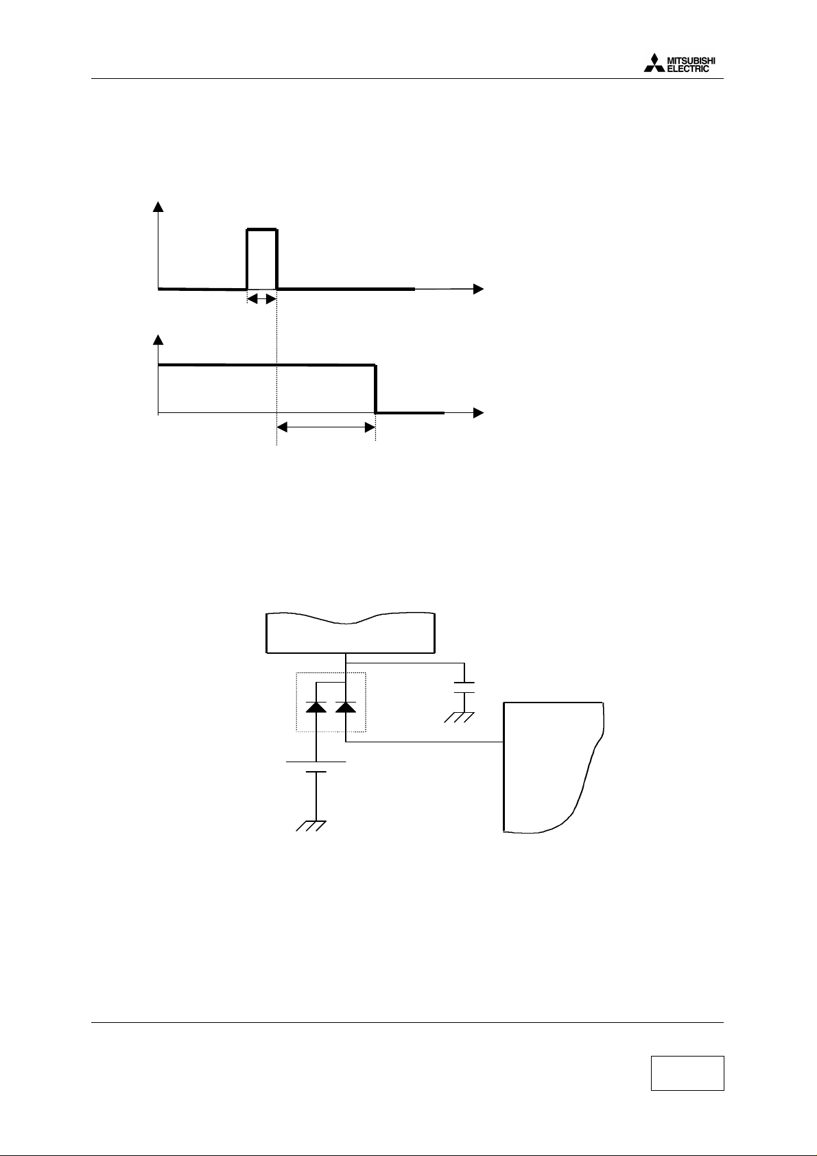
Page 10
a) With battery
PWRKEY
t
BBPWR
IC300 pin L8
t
MUPSU
IC100 pin49
t
Level 3 Service Manual
COSMO
During these mode TESTPS and EXPS equal low voltage level.
A high voltage level on MUPSU implies regulators REG 4, REG 6, REG 7, REG 8 are active.
b) With Interface and I/O connector (Testmode) :
TESTPS
J103 pin3
to t
t0= connexion I/O cable
When you connect I/O connector, MUPSU and BBPWR signals have the same waveform at
TESTPS.
During this condition PWRKEY and EXPS equal low voltage level.
c) With AC/DC Charger, Cigar Light Adapter and DeskTop Charger.
EXPS
J103 pin 2
t0
t0= connection by external power.
When you connect an accessory, MUPSU and BBPWR signals have the same waveform that
TESTPS.
During this condition PWRKEY and TESTPS equal low voltage level
Version A Mitsubishi Electric Telecom Europe S.A.
Date: 04/00 ZA le Piquet 35370 Etrelles
6/29
Phone: +33 2 99 75 71 00
Fax: + 33 2 99 75 71 47
Page 11
Level 3 Service Manual
COSMO
2.g Power off.
PWRKEY
t
1s
BBPWR
MUPSU
t
5s
SW checks if POWER-key (Row[0],Col[2]) is pressed during 1second
Then after 5 s, SW disactivates BBPWR output to switch One-C power supply off, then POWER-Key
can be released.
2.h Real Time Clock
Real time clock is in ONE C (IC300) and energy is provided:
By IC100 (pin 48) via D105, when the main battery is connected.
By BT100 (back up battery) via D105, when the main battery is empty or not connected
IC300
D105 C305
BT100
VDD_RTCVCC
IC100
REG80
Mitsubishi Electric Telecom Europe S.A. Version A
ZA le Piquet, 35370 Etrelles Date: 04/00
Phone: +33 2 99 75 71 00
Fax: + 33 2 99 75 71 47
7/29
Page 12

Level 3 Service Manual
3. RF Section.
3.a Frequency range.
3.a.1 E-GSM Frequency :
124 Channels. 1≤ N ≤124 and 50 Channels. 975 ≤ N ≤1023 and 0
Receive frequency : 925.2~959.8 MHz
RX frequency = 935.0+0.2*N for (1≤ N ≤124) and 935.0+0.2*(N-1024) for ( 975 ≤ N ≤1024)
Transmit frequency : 880.2~914.8 MHz
TX frequency = 890.0+0.2*N for (1≤ N ≤124) and 890.0+0.2*N for ( 975≤ N ≤1024)
E-GSM BAND
COSMO
880 TX
35 MHz 35 MHz
RF-PLL E-GSM BAND
1150
TX/RX
35 MHz
915 MHz
45 MHz
1185 MHz
925 RX 960 MHz
RX 1st IF is 225 MHz
RX 2nd IF is 45 MHz
3.a.2 DCS Frequency :
374 Channels. 512≤ N ≤885
Receive frequency : 1805.2~1879.2 MHz
RX frequency = 1805.2+0.2*(N-512).
Transmit frequency 1710.2~1784.8 MHz
TX frequency = 1710.2+0.2*(N-512).
DCS BAND
1710 TX
RF-PLL DCS BAND
1574.2
1785 MHz
75 MHz 75 MHz
95 MHz
TX
75 MHz
1805 RX 1880 MHz
1650.8 MHz
1580 1655 MHzRX
75 MHz
RX 1st IF is 225 MHz
RX 2nd IF is 45 MHz
Version A Mitsubishi Electric Telecom Europe S.A.
Date: 04/00 ZA le Piquet 35370 Etrelles
Phone: +33 2 99 75 71 00
8/29
Fax: + 33 2 99 75 71 47
Page 13

Level 3 Service Manual
COSMO
Examples with the usual channels and frequencies:
RX freq TX Freq RF Freq RX RF Freq TX IF Freq RX IF Freq TX
Unit MHz MHz MHz MHz MHz MHz
GSM
1 935.2 890.2 1160.2 1162.2 540 544
62 947.4 902.4 1172.4 1170.4 540 536
124 959.8 914.8 1184.8 1182.8 540 536
975 925.2 1085 1150.2 1152.2 540 544
1000 930.2 1090 1155.2 1157.2 540 544
1023 934.8 1094.6 1159.8 1161.8 540 544
37 942.4 897.4 1167.4 1169.4 540 544
DCS
512 1805.2 1710.2 1580.2 1574.2 540 544
698 1842.4 1747.4 1617.4 1611.4 540 544
885 1879.8 1784.8 1654.8 1650.8 540 536
Mitsubishi Electric Telecom Europe S.A. Version A
ZA le Piquet, 35370 Etrelles Date: 04/00
Phone: +33 2 99 75 71 00
Fax: + 33 2 99 75 71 47
9/29
Page 14

3.b Synthesiser Circuit Description
CLK
SDATA
SLE
PWD_SYNTH
PLL IF
PLL RF
VCO IF
VCO RF
IC601
Level 3 Service Manual
COSMO
IC602
/2
1080 MHz 540 MHz
1150-1185 MHz E-GSM band
1575-1655 MHz DCS band
TCXO
13 MHz
Switching between GSM and DCS band is performed by programming the SI4133G (IC601) with the
serial data in BBE from CPU.
The serial data lines are connected directly to the serial input pin of the PLL & VCO IC (IC 601), and
are used to program the 2 PLLs & 2 VCOs of the IC.
The SI4133G has two PLLs : one is variable frequency (RF PLL), and the other is fixed frequency (IF
PLL).
RF-PLL : variable frequency PLL for RX and TX for both GSM and DCS bands.
Oscillation Frequency Ranges For E-GSM Band / 1150 – 1185 MHz
For DCS TX / 1575 – 1650 MHz
For DCS RX / 1580 – 1655 MHz
IF-PLL : Fixed frequency 1080 MHz (C Version) for IF of RX and 1072 or 1088 MHz for IF of TX for
both E-GSM and DCS bands.
The signal BANDSW controls the E-GSM/DCS Band switching.
BANDSW RF BAND
0 E-GSM
1 DCS
X600
In order to achieve the channel spacing, the reference frequency is set to 200 kHz.
Version A Mitsubishi Electric Telecom Europe S.A.
Date: 04/00 ZA le Piquet 35370 Etrelles
10/29
Phone: +33 2 99 75 71 00
Fax: + 33 2 99 75 71 47
Page 15

Level 3 Service Manual
COSMO
3.c RF Block Diagram.
GSM RX : 925 - 960 MHz
FL504
TR504
FL503
DCS TX : 1710 - 1785 MHz
DCS RX : 1805 - 1880 MHz
FILTER
+
SWITCH
SW700
GSM TX : 890 – 915MHz
Z701
COUPLEUR
Z700
FILTER
FL501
COMP.
IC601
PLL & VCO
IF
PLL
RF
PLL
TCXO
13 MHz
POWER
AMPLI.
IC701
AMPLI
TR502
AT700
ATTN :
9dB GSM
8dB DCS
AT701
FILTER
FL502
IC602
/ 2
GSM : 1150 - 1185 MHz
TX DCS : 1575 – 1650 MHz
RX DCS : 1580 – 1655 MHz
TX
VCO
IC700
RX : 540 MHz
TX : 536 – 544 MHz
DEMO
IC600
MOD
GSM : 270 MHz
LOOP
FILTER
DCS: 135 MHz
RX
I/Q
TX
I/Q
APPCNT
IC710
Mitsubishi Electric Telecom Europe S.A. Version A
ZA le Piquet, 35370 Etrelles Date: 04/00
Phone: +33 2 99 75 71 00
Fax: + 33 2 99 75 71 47
11/29
Page 16

3.c.1 Reception Block Diagram.
Level 3 Service Manual
COSMO
Mecha
SW
SW700
CLK
SDATA
SLE
GSM SUPPLY
DCS SUPPLY
DCS RX : 1805 - 1880 MHz
IF
PLL
RF
PLL
TCXO
13 MHz
FL 504
GSM RX : 925 – 960 MHz
FL 501
TR503
LNA
GSM & DCS :1080MHz
RX GSM : 1150 - 1185MHz
RX DCS : 1580 – 1655MHz
FL 503TR504
FL 502
1/2
IC602
GSM & DCS : 540MHz
FL 500
FILTER
225
MHz
270 MHz
1/2 1/2
1/2
90 MHz
45 MHz
45 MHz
RX
I,Q
DEMOD
Description of Reception Block Diagram.
E-GSM band (925-960 MHz).
Incoming RF signal from aerial is filtered and switched to the RX GSM path through SW700 . The
signal is filtered by FL504 , before being amplified by TR504 , and is further filtered by FL503. Then,
the signal input sent to RF-IC (IC600) in a first mixer stage. The RF signal (925-960 MHz) is mixed
with the RF-PLL Frequency (1150-1185 MHz) coming from IC601 (PLLs & VCOs). For the channel 1,
the output signal of the mixer is 225 MHz (1150 - 925 = 225 MHz), and is filtered by FL500.
DCS band (1805-1880 MHz).
Incoming RF signal from aerial is filtered and is switched to the RX DCS path through SW700 . The
signal is filtered by FL501 , before being amplified by TR503 , and is further filtered by FL502. Then,
the signal input to RF-IC (IC600) in a first mixer stage. The RF signal (1805-1880 MHz) is mixed with
the RF-PLL Frequency (1580-1655 MHz) coming from IC601 (PLLs & VCOs) via IC602 (RF-VCO).
For the channel 1, the output signal of the mixer is 225 MHz (1805 Mhz-1575 MHz = 225 MHz), and
is filtered
by FL500.
For the E-GSM and DCS bands.
The first intermediate frequency is 225 MHz. Then, this frequency is filtered by FL 500 before input to
the second mixer stage. The first IF (225 MHz) is mixed with the 270 MHz (Fixed Frequency PLL
540 /2 = 270 MHz), to a second IF 45 MHz. The second IF is demodulated to Base Band (IC300) I/Q
phase demodulated signals. RF-IC (IC600) provides automatic gain control.
IC600 includes a quadrature demodulator. The second IF signal (45 MHz) is demodulated to I, Q
balanced signals for One-C.
Version A Mitsubishi Electric Telecom Europe S.A.
Date: 04/00 ZA le Piquet 35370 Etrelles
Phone: +33 2 99 75 71 00
12/29
Fax: + 33 2 99 75 71 47
Page 17

Level 3 Service Manual
COSMO
3.c.2 Transmission Block Diagram.
CLK
SDA
TA
SLE
Mecha
SW
SW
SW
GSM SUPPLY
DCS : 1710 - 1785MHz
DCS SUPPLY
IF
PLL
RF
PLL
TCXO
GSM : 880 – 915MHz
Z701
Coupler
Z700
Coupler
GSM & DCS :1072 or 1O88 MHz
IC602
/ 2
IC701
HPA
GSM & DCS : 536 or 544 MHz
TX GSM : 1150 - 1185MHz
TX DCS : 1575 – 1650MHz
AT700
Attn
9dB
AT701
Att
n
8dB
1/2
DCS : 1710 - 1785MHz
GSM : 880 – 915MHz
GSM
DCS : 268 OR 272 MHz
TX
VCO
DCS
sw
PHA
DET
1 / 2
GSM : 270 MHz
DCS : 135 MHz
IC600
TX
I,Q
MOD
IC710
APCCNT
Description of Transmission Block Diagram
The direct and phase shifted signals are then fed to I and Q modulators inside the IC600. I and Q data
components are fed into the IC600. The output from the two modulators is summed and fed out of
pin 11. The GMSK signal leaves the modulator of IC 600, and is amplified also inside IC600.
E-GSM Band (880-915 MHz).
A phase locked loop is created around the TXVCO IC700. The output is fed into IC600 and converted
to 270 MHz (135 MHz on DCS) by mixing with RFVCO at 1150-1185 MHz . This 270 MHz signal is
compared with the 270 MHz signal from the modulators, and the error signal is used to control the
TXVCO. Note that the error signal on TP700 will have a DC component to control frequency, and an
AC component at approx 270 kHz to control phase changes. Then the signal is filtered, amplified by
TR702, and further filtered before input to the power amplifier (IC702).From the PA, the output goes
through coupler Z701, is switched to the TX path and is filtered by SW700. The signal then goes up to
the antenna.
Mitsubishi Electric Telecom Europe S.A. Version A
ZA le Piquet, 35370 Etrelles Date: 04/00
Phone: +33 2 99 75 71 00
Fax: + 33 2 99 75 71 47
13/29
Page 18

Level 3 Service Manual
COSMO
DCS Band (1710-1785 MHz).
A phase locked loop is created around the TXVCO IC700. The output is fed into IC600 and converted
to 135 MHz (270 MHz on GSM) by mixing with RFVCO at 1575-1650 MHz. This 135 MHz signal is
compared with the 135 MHz signal from the modulators, and the error signal is used to control the
TXVCO. Note that the error signal on TP700 will have a DC component to control frequency, and an
AC component at approx 270 kHz to control phase changes. Then the signal is filtered, amplified by
TR712, and further filtered before input to the power amplifier (IC702). From the PA, the output goes
through coupler Z700, is switched to the TX path and is filtered by SW700. The signal then goes up to
the antenna.
3.c.3 Output power control.
Dual HPA (IC701)
DCS ATTN AT701
From TXCO
DCS RF OUT
(IC700)
From TXCO
GSM RFOUT
(IC700)
-8 dB
-9 dB
GSM ATTN AT700
VAPC FOR HPA
Comparison error
AMP (IC710)
Directional
Coupler
( Z700)
Directional
Coupler
( Z701)
Detecting
Circuit
(D700)
SW700
SW700
_
TX3SW
+
APCCNT
APCCNT: is the reference waveform voltage for a TX burst (provided by IC300).
TX3SW: This control signal is used to switch on/off the operational amplifier of the APC Loop (IC710).
H Level: Detecting Circuit and comparison Error AMP is active.
L Level: Detecting Circuit and comparison Error AMP is not active.
RF signal is rectified by voltage doubler Schottky barrier diodes D700. This level is compared with
APCCNT. The result of the comparison is used to vary the gain of the HPA IC701.
The APCCNT signal input from the base band circuit (IC300) contains the burst shaping information
and the power level to be set among the 15 power levels defined by the GSM, or the 16 power levels
defined by the DCS specifications. It controls the output power level by a feed-back loop (Automatic
Power Control )
E-GSM DCS
PCL 05 → + 33 dBm PCL 00 → + 30dBm
PCL 19 → + 5 dBm PCL15 → + 0 dBm
Version A Mitsubishi Electric Telecom Europe S.A.
Date: 04/00 ZA le Piquet 35370 Etrelles
Phone: +33 2 99 75 71 00
14/29
Fax: + 33 2 99 75 71 47
Page 19

Level 3 Service Manual
COSMO
4. Speech coder.
4.a Features
Audio is sampled at 8 kHz rate, and divided into 20 ms blocks of 160 samples per block. Each 20 ms
block is characterised by 260 bits i.e. 13 kbits/sec. The resulting signal is processed by a regular
pulse excitation - long term predictor (RPE - LTP) codec. This yield a digital representation of vocal
chord vibrations, together with the filter characteristics which must be applied to them to make voice
sounds.
The most significant block of 182 bits will go through error correction and become 378 bits. The less
critical group of 78 bits will not go through error correction and will just be summed with the 378 bits
which will yield 456 bits.
Voice
SPEECH CODER
error correction
block coding
378 bits
378 bits
8 blocks of 57 bits
57 57 5757 575757 57
5757 5757
time slot time slot
These 456 bits are then separated in 8 blocks of 57 data bits.
These blocks are interleaved with adjacent blocks to guard against burst errors and broken up into
blocks of 114 bits for transmission. This block of 114 bits are the data bits of the timeslot.
160 voice samples = 20 ms
260 bits (20 ms)182 bits 78 bits
78 bits
456 bits
next speech block
5757 57
Timing data is added, and the resulting bit stream is fed to the Gaussian Minimum Shift Keying
(GMSK) modulator, where the bits are taken two at a time and used to smoothly change the phase of
an RF carrier according to bit combination.
4.b Full rate / Half rate / Enhanced full rate.
The data rate of 13 kbits/s ( full rate ) is considerably lower than for direct speech digitising as in
PCM. Now more advanced voice coders cut this to 5.6 kbits/s ( half rate coding ).
The enhanced full rate, is just a full rate with a different speech coder which improves the
transmission quality.
Mitsubishi Electric Telecom Europe S.A. Version A
ZA le Piquet, 35370 Etrelles Date: 04/00
Phone: +33 2 99 75 71 00
Fax: + 33 2 99 75 71 47
15/29
Page 20

Level 3 Service Manual
COSMO
Version A Mitsubishi Electric Telecom Europe S.A.
Date: 04/00 ZA le Piquet 35370 Etrelles
16/29
Phone: +33 2 99 75 71 00
Fax: + 33 2 99 75 71 47
Page 21

Level 3 Service Manual
Speaker
Speaker
I/O connector J302 (pin 1 & 2)
COSMO
5. Analogue Audio.
The audio part is managed by the One-C circuit (IC300).
5.a Buzzer.
Diagram
2.8V bat
5.b Speaker (RX audio).
Diagram :
IC300 (One C)
PW01P
PW01N
PW02P
PW02N
IC300 (One C)
alerter
Buzzer
TR350
Internal
receiver
Head set
Hand-free
I/O connector J103 (pin 13 & 1)
5.c Micro (TX audio).
Diagram :
IC300 (One C)
VX1P
VX1N
MICREFP
MICREFN
VXI2P
VXI2N
J103 (pin 18 & 17)
J103 (pin 1 & 12)
J100 (pin 12 & 14)
Mitsubishi Electric Telecom Europe S.A. Version A
ZA le Piquet, 35370 Etrelles Date: 04/00
Phone: +33 2 99 75 71 00
Fax: + 33 2 99 75 71 47
Internal micro
Headset micro
Hand free micro
17/29
Page 22

Level 3 Service Manual
COSMO
6. Testmode Software
For M4 family, test mode is not directly possible from the mobile, indeed relevant software is
available on PC only.
Basic test mode functions (delete data user, print labels, download of settings) are available in
MSTools (7.00 and more) software (see level 2 service manual), download of mobile software is
available with IPLTrium software (see level 2 service manual).
More advanced testmode functions to test the mobile are available in MTS software. This software
can be used only with a runtime engine TEST STAND.
When making measurement on the board itself, it is possible to power the board from the M4
interface box
6.a Equipment installation
Mobile without battery
RADIOCOMMUNICATION TESTER
GPIB Connection for Autotest only
(not requested for test mode)
External supply
4.5V
1.5 A
RF Cable NN 50 OHMS 0.8
(FT7Y005610)
Serial Cable
FT7Y002110
NSMA ADAPTATOR FEMALE
(FT7Y010010)
The test mode is used to control or adjust mobile parameters.
You must have the following requirements :
• Radio-communication tester
• Cosmo RF cable
• Cosmo Interface cable
• M4 Interface Box
• Serial Cable
• Computer under Windows 95 or 98 (PII 350 MHz 64 Mb recommended)
• Resolution min: 800*600 Pixels
RF CABLE
FT7Y006110
M4 Interface Box
FT7Y009410
INTERFACE CABLE
FT7Y0117B
If you want to use autotest function which is included in MTS, then your Radio-communication tester
must be a Rohde & Schwarz CMD55 (with firmware 3.6 and GPIB interface) and your computer must
have GPIB interface. The result of autotest (measurement values) is displayed as HTML file.
Version A Mitsubishi Electric Telecom Europe S.A.
Date: 04/00 ZA le Piquet 35370 Etrelles
Phone: +33 2 99 75 71 00
18/29
Fax: + 33 2 99 75 71 47
Page 23

Level 3 Service Manual
!
COSMO
6.b Software (MTS) installation
This part describes how to install the different components of MTS depending of the functions of MTS
you want to use.
6.b.1 Simple Setup :
If you want to have only the test mode functions (control and adjust RF parameters), follow this
procedure:
Launch Setup.exe on MTS CD ROM root.
Select the Custom Setup Type in Setup Type selection window and click on
Select the component as follow :
a MTS Application
a Test Stand Engine
GPIB Software
a NI-VISA Software
Internet Explorer
Next >
Then continue the 3 setup programs before, reboot.
MTS after sale service is now available in ÿ Start .> Program.>. MTS After Sale Service
6.b.2 Complete Setup :
If you want to have all the functions of MTS (control and adjust the RF parameters, execute and
parameter the autotests), follow this procedure :
Launch Setup.exe on MTS CD ROM root.
Select the Typical Setup Type in Setup Type selection window and click on
Then continue the setup program until Reboot information window and reboot.
MTS after sale service is now available in ÿ Start > Program > MTS After Sale Service
Before you launch an autotest, you must invalidate the step : 4301 DIO initialisation
For that you have to turn the Execution mode switch on run selected step in the autotest page.
Next >
Mitsubishi Electric Telecom Europe S.A. Version A
ZA le Piquet, 35370 Etrelles Date: 04/00
Phone: +33 2 99 75 71 00
Fax: + 33 2 99 75 71 47
19/29
Page 24

6.c Software (MTS) description
When you launch MTS from start menu you the main screen is displayed :
Testmode
(click here to enter in…)
Level 3 Service Manual
COSMO
Identificatio
n
(click here to display
PCA number, IMEI,
Hardware version,
MMI Testmode interface : description of functions
TestMode
(click here to enter and
stop test mode
Autotest
Cosmo
(click here to execute
an…)
Calibration
(click here to adjust the
RF losses parameters)
Exit
(click here to exit, the
WINDOWS © commands
are not available)
Quit
(click here to exit, the
WINDOWS © commands
are not available)
Battery
(click here to measure
the voltage of the
Mobile
(click here to know the
software version )
RF
Parameters
(to activate TX or RX, to
change the band, the
channel, the PCL… )
RF
(click here to control and
adjust TX, RX, TCXO)
MMI
(click here to activate
backlight, LCD, vibrator
and RTC)
Audio
(click here to activate the
buzzer and to select
audio path)
Version A Mitsubishi Electric Telecom Europe S.A.
Date: 04/00 ZA le Piquet 35370 Etrelles
Phone: +33 2 99 75 71 00
20/29
Fax: + 33 2 99 75 71 47
Page 25

Level 3 Service Manual
COSMO
6.d Enter in test mode:
The mobile can be turned in test mode from two different ways :
Using test mode code (hold the * and enter 5472) and PC cable (FZA0056A)
or
Using the M4 interface box (FT7Y009410) and Cosmo interface cable (FT7Y0117B)
With the “Alimentation mobile” switch up & “boot RI” switch down.
When the mobile displays:
Mitsubishi
M4 Testmode
You can enter in Testmode, for that, choose Testmode> Enter menu as follow.
Information
window
When the communication is established between mobile and computer the information window
displays
Start Testmode Passed
Mitsubishi Electric Telecom Europe S.A. Version A
ZA le Piquet, 35370 Etrelles Date: 04/00
Phone: +33 2 99 75 71 00
Fax: + 33 2 99 75 71 47
21/29
Page 26

Level 3 Service Manual
COSMO
6.e Power adjustments
To enter in Power adjustments, choose RF menu, Adjustment, Adjustment TX, Adjustment burst
as follow :
Then, the Ramping parameters Window is displayed as follow :
Version A Mitsubishi Electric Telecom Europe S.A.
Date: 04/00 ZA le Piquet 35370 Etrelles
22/29
Phone: +33 2 99 75 71 00
Fax: + 33 2 99 75 71 47
Page 27

Level 3 Service Manual
COSMO
6.f Receive adjustments
To adjust RSSI (if RX level is not good, for example), you have to process to different steps :
RX SPLIT and RSSI ADJUSTMENT
For RX Split we choose :
RF menu, Adjustment, Adjustment RX, Split RX as follow :
Then we fix RX split at the right value :
For the E-GSM band the number of sub-bands is 2
L range: 975 to 110
H range: 110 to 124
Adjustments on Channels 55 and 117, the RX split window should be as follow :
Mitsubishi Electric Telecom Europe S.A. Version A
ZA le Piquet, 35370 Etrelles Date: 04/00
Phone: +33 2 99 75 71 00
Fax: + 33 2 99 75 71 47
23/29
Page 28

DCS band is split in 3 sub-bands is
We split the DCS band as follow : L range : 512 to 539
M range : 539 to 850
H range : 850 to 885
Adjustments on Channels 525, 698 and 870
The RX split window should be as follow :
Level 3 Service Manual
COSMO
Now we can adjust RSSI for each sub band
Version A Mitsubishi Electric Telecom Europe S.A.
Date: 04/00 ZA le Piquet 35370 Etrelles
24/29
Phone: +33 2 99 75 71 00
Fax: + 33 2 99 75 71 47
Page 29

Level 3 Service Manual
COSMO
For RSSI ADJUSTMENT, we choose :
RF menu, Adjustment, Adjustment RX, Adjustment RSSI (rapport AGC).
Then we get the RSSI window :
To adjust RSSI, we input a GMSK modulated signal (67.7 kHz shifted) at level and channel as follow:
Step Channel Level
1 55 -82.5
2 55 -31.5
3 117 -82.5
4 117 -31.5
5 525 -82.5
6 525 -31.5
7 698 -82.5
8 698 -31.5
9 870 -82.5
10 870 -31.5
If the RX level measurement is not good in E-GSM we adjust only the E-GSM band (step 1 and 2)
If the RX level measurement is not good in DCS we adjust only the DCS band (step 3 to 8).
Mitsubishi Electric Telecom Europe S.A. Version A
ZA le Piquet, 35370 Etrelles Date: 04/00
Phone: +33 2 99 75 71 00
Fax: + 33 2 99 75 71 47
25/29
Page 30

Level 3 Service Manual
COSMO
7. Basic Adjustment.
7.a Power Adjustment.
For the COSMO, Mitsubishi uses only IC701. Each mobile is adjusted in the factory and the TX
parameters (Power Control Level values and ramping values) are stored in the Serial Flash (IC 206)
About the adjustment value of TX Power, see the following table.
E-GSM DCS
Ch-62
PCL
5
6
7
8
9
10
11
12
13
14
15
16
17
18
19
Power Level
(dBm)
32.5 +/-2dB
31 +/-3dB
29 +/-3dB
27 +/-3dB
25 +/-3dB
23 +/-3dB
21 +/-3dB
19 +/-3dB
17 +/-3dB
15 +/-3dB
13 +/-3dB
11 +/-5dB
9 +/-5dB
7 +/-5dB
5 +/-5dB
tolerance Ch-698
PCL
0
1
2
3
4
5
6
7
8
9
10
11
12
13
14
15
Power Level
(dBm)
30 +/-2dB
28 +/-3dB
26 +/-3dB
24 +/-3dB
22 +/-3dB
20 +/-3dB
18 +/-3dB
16 +/-3dB
14 +/-3dB
12 +/-4dB
10 +/-4dB
8 +/-4dB
6 +/-4dB
4 +/-4dB
2 +/-5dB
0 +/-5dB
tolerance
Version A Mitsubishi Electric Telecom Europe S.A.
Date: 04/00 ZA le Piquet 35370 Etrelles
26/29
Phone: +33 2 99 75 71 00
Fax: + 33 2 99 75 71 47
Page 31

Level 3 Service Manual
COSMO
Example of adjustment :
E-GSM Table:
TX ramp adjustment for EGSM band
PCL_Threshold = PCL5
Level
DBm
PCL5 32.5 (Pmax of PCL15)-36 50 23 9 20 12
PCL6 31 (Pmax of PCL15)-36 50 22 10 20 12
PCL7 29 (Pmax of PCL15)-37 50 22 10 20 12
PCL8 27 (Pmax of PCL15)-37 50 22 10 19 12
PCL9 25 (Pmax of PCL15)-39 50 22 10 19 12
PCL10 23 (Pmax of PCL15)-42 50 22 10 19 12
PCL11 21 (Pmax of PCL15)-44 50 22 10 19 12
PCL12 19 (Pmax of PCL15)-44 50 22 10 19 12
PCL13 17 (Pmax of PCL15)-45 50 23 8 19 12
PCL14 15 (Pmax of PCL15)-47 50 23 9 19 12
PCL15 13 (Pmax of PCL15)-49 50 22 10 19 12
PCL16 11 (Pmax of PCL15)-52 50 21 11 19 12
PCL17 9 (Pmax of PCL15)-56 50 17 13 19 12
PCL18 7 (Pmax of PCL15)-58 50 17 11 19 12
PCL19 5 (Pmax of PCL15)-58 50 15 12 19 12
Pmin up Pmin Dn Pmin up
time
Ramp up
time
Pmin dn
time
Ramp dn
time
Mitsubishi Electric Telecom Europe S.A. Version A
ZA le Piquet, 35370 Etrelles Date: 04/00
Phone: +33 2 99 75 71 00
Fax: + 33 2 99 75 71 47
27/29
Page 32

DCS Table:
TX ramp adjustment for DCS band
Level 3 Service Manual
COSMO
Level
DBm
Pmin up Pmin Dn Pmin up
time
Ramp up
time
Pmin dn
Time
Ramp dn
time
PCL0 29.5 (Pmax of PCL12)-24 50 23 9 20 11
PCL1 28 (Pmax of PCL12)-24 45 23 9 20 11
PCL2 26 (Pmax of PCL12)-24 45 23 9 20 11
PCL3 24 (Pmax of PCL12)-24 45 22 10 19 11
PCL4 22 (Pmax of PCL12)-26 45 22 10 19 12
PCL5 20 (Pmax of PCL12)-27 45 22 10 19 12
PCL6 18 (Pmax of PCL12)-28 45 22 10 19 12
PCL7 16 (Pmax of PCL12)-28 45 22 10 19 12
PCL8 14 (Pmax of PCL12)-29 45 24 8 19 12
PCL9 12 (Pmax of PCL12)-29 45 24 8 19 12
PCL10 10 (Pmax of PCL12)-31 45 23 9 19 12
PCL11 8 (Pmax of PCL12)-32 45 23 9 19 12
PCL12 6 (Pmax of PCL12)-33 45 22 9 19 12
PCL13 4 (Pmax of PCL12)-34 45 21 10 19 12
PCL14 2.5 (Pmax of PCL12)-36 45 18 11 19 12
PCL15
1
(Pmax of PCL12)-36 45 17 11 19 12
Version A Mitsubishi Electric Telecom Europe S.A.
Date: 04/00 ZA le Piquet 35370 Etrelles
Phone: +33 2 99 75 71 00
28/29
Fax: + 33 2 99 75 71 47
Page 33

Level 3 Service Manual
COSMO
7.b RSSI control.
To control RSSI go back to page 22 of the manual.
Set your radiocommunication tester at a given reference and check RSSI:
REF Gene RSSI
-83.5 dBm 27 +/- 4
-60.5 dBm 50 +/- 4
8. Software Version .
The software version is coded with 8 digits, evolving in the following order : 0, 1, 2, ...,9, A, B, ...,Z, a,
b,...,z.
F H S V E Vf Ef Vc
F : Family ex : 1 M3, 2 M4, ….
H : Hardware ex : 1 GALAXY, 5 GEO, 3 ARIA,E WAP,J COSMO….
S : Software ex :
V : Version ex :
E, Vf, Ef, Vc are Mitsubishi Code.
Mitsubishi Electric Telecom Europe S.A. Version A
ZA le Piquet, 35370 Etrelles Date: 04/00
Phone: +33 2 99 75 71 00
Fax: + 33 2 99 75 71 47
29/29
Page 34

Level 3 Service Manual
COSMO
Mitsubishi Electric reserves the right to make changes to its products at any time to improve reliability
or manufacturability. Mitsubishi Electric does not assume any liability arising from the use of any
device or circuit described here in, nor does it convey any license under its patent rights or the rights
of others.
Version A Mitsubishi Electric Telecom Europe S.A.
Date: 04/00 ZA le Piquet 35370 Etrelles
30/29
Phone: +33 2 99 75 71 00
Fax: + 33 2 99 75 71 47
 Loading...