

Page 1
TC0169e
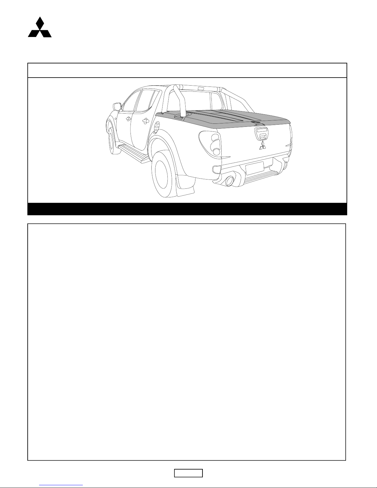
3PIECE HARD TONNEAU COVER
INSTALLATION INSTRUCTIONS
VEHICLE DESCRIPTION: Mitsubishi MN Triton onwards
PLEASE KEEP INSTRUCTIONS IN GLOVE BOX FOR FURTHER USE
29/10/10ISSUE05Page 1 of 13
PLEASE REFER TO PAGE 13, OF THIS INSTRUCTION FOR A LIST OF PARTS AND QUANTITIES.
WARNING!
When in the closed position, Tonneau Cover must be latched and tailgate must be closed! Failure to do so could result in unexpected opening of the
Tonneau Cover from sudden wind gusts, which could cause damage to the vehicle and/or your Tonneau Cover!
MAINTENANCE:
• Only use cleaners, waxes, or products that are labeled safe for use on plastics. Avoid the use of any chemicals to clean your Tonneau Cover unless
labelled safe for plastics. Avoid use of abrasive type cleansers as they may dull the finish.
• The gas struts are self lubricating and should only be cleaned occasionally with a damp cloth. Premature seal failure will result if solvents or
lubricants are used to clean struts.
• The locking mechanisms & Latches only require occasional lubrication with Graphite Powder. DO NOT use any other lubricants or oils.
Using alternative products will VOID Warranty.
• All installation hardware and fasteners must be checked every so often for tightness.
TONNEAU COVER - IMPORTANT:
• Do not stand/sit or rest heavy objects on Tonneau Cover.
• Humans or animals are not to be under the closed Tonneau Cover at any time.
• Securely latch Tonneau Cover before operating vehicle.
• Do not carry open volatile chemicals with Tonneau Cover installed.
• If contact with volatile chemicals occurs clean Tonneau Cover with mild detergent and water solution.
• Read instructions carefully before installation. It is strongly recommended that installation is conducted by an authorized dealer.
• This product must be installed exactly as specified in these instructions. Failure to do so may result in improper fit and/or retention.
• Recommend installation by 2 people.
• Approximate fitting time is 1 ½ hours.
PAINTING INSTRUCTIONS: (IF UNPAINTED)
• Prior to painting, clean all surfaces to be painted using clean water and a mild detergent, do not use lacquer thinner or any solvent based products.
Wipe completely dry.
• Best results will be achieved by wiping the areas to be painted with a tack rag just prior to painting.
• Select a top coat and clear paint that is suitable for ABS (Acrylonitrile-Butadiene-Styrene).
• Automotive paint systems, such as Acrylics or Two Packs, can be applied directly to the components. However, some paints may require a primer.
If recommendations on paint specification are not followed, cracking of the part or degradation to the material may result. In all paint systems,
aromatic hydrocarbons and alkalies are best avoided to reduce damage to the material properties.
• If using a paint system which requires baking, do not expose the product to temperatures above 70° C (155° F).
• Allow a minimum of 8 hours after baking before installation on the vehicle.
Accessory
MITSUBISHI
MOTORS
Page 2
MITSUBISHI TRITON 3 PIECE TONNEAU COVER
ISSUE05
FIG. 3
FIG. 2
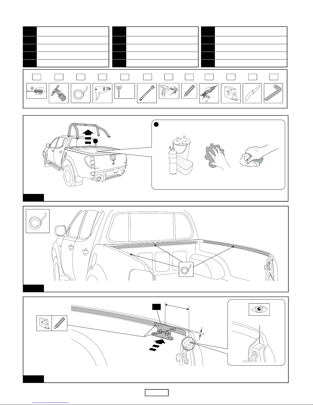
APPLY MASKING TAPE TO THE INNER BEDRAIL AS SHOWN.
FIG. 1
REMOVE SPORTS BAR AND RETAIN ALL HARDWARE. THOROUGHLY CLEAN AND DRY THE INSTALLATION AREA.
TC0169e
29/10/10Page 2 of 13
1
2
MEASURE AND MARK A LINE ON THE SIDE RAIL 108MM FROM THE REAR OF THE SIDE RAIL AS SHOWN. POSITION “FACE B ”
OF LOCK STRIKER BRACKET TO SIDE OF SIDE RAIL 18MM DOWN FROM TOP OF SIDE RAIL. ALIGN NOTCH TO PREVIOUSLY
MARKED CENTRELINE. MARK THE POSITION OF THE TWO (2) LARGER HOLES AS SHOWN. REPEAT FOR THE OTHER SIDE.
108mm
MEASURE FROM REAR
OF FLANGE
18mm
A
B
4
RECOMMENDED TOOLS LIST
TOOL NAME
Caulking Gun & Silicon
Tape Measure
Knife
Allen Key
9
10
11
12
NO.TOOL NAME
Phillips Head Screwdriver
Rivet Gun
Masking Tape
Drill
1
2
3
4
NO. TOOL NAME
Ø5mm & Ø6mm Drill Bit
Spanners & Sockets
Hammer & Centre Punch
Pencil
5
6
7
8
NO.
1 2 3 4 5 6 7 8 9 10
Ø5mm
Ø6mm
11 12
Page 3
FIG. 4
TC0169eMITSUBISHI TRITON 3 PIECE TONNEAU COVER
29/10/10Page 3 of 13
ISSUE05
FIG. 7
FIG. 6
REMOVE THE MASKING TAPE FROM THE INSIDE OF THE SIDE RAILS ONLY. APPLY RUST INHIBITOR TO ALL THE DRILLED HOLES.
FIG. 5
REMOVE MASKING TAPE
APPLY RUST INHIBITOR
1
2
23
ALIGN LOCK STRIKER BRACKETS WITH PREVIOUSLY DRILLED HOLES, ENSURING BRACKETS ARE PARALLEL WITH TOP OF
SIDE RAIL AND SECURE WITH M6 BOLTS, M6 FLAT WASHERS, M6 SPRING WASHERS AND M6 NUTS AS SHOWN.
TIGHTEN TO TORQUE 12Nm.
CENTRE PUNCH THE TWO (2) FRONT HOLE POSITIONS AND DRILL Ø5MM HOLES. CENTRE PUNCH THE TWO (2) REAR
HOLE POSITIONS AND DRILL Ø6MM HOLES. REPEAT FOR THE OTHER SIDE OF THE VEHICLE.
CENTRE PUNCH,
THEN DRILL Ø5MM
HOLES
CENTRE PUNCH,
THEN DRILL Ø6MM
HOLES
Ø5mm
Ø6mm
20mm
ENSURE BRACKET IS
PARALLEL WITH
TOP OF SIDE RAIL
A
B
7
8
9
20
MEASURE FROM THE FRONT RAIL INSIDE OF THE TUB AND MARK THE DISTANCES AS SHOWN. REPEAT FOR THE OTHER SIDE.
MEASURE FROM
FRONT RAIL
INSIDE OF THE TUB
37mm
738mm
738mm
28mm
Page 4
ATTACH THE GAS STRUT BRACKETS (BOTH SIDES) TO THE SIDE RAILS USING POP RIVETS AS SHOWN.
MEASURE THE LENGTH OF EXPOSED THREAD (X MM) FROM THE BOTTOM OF THE NUT TO THE END OF THE THREAD.
MEASURE LENGTH (X MM) ON THE RUBBER THREAD CAP AND CUT TO LENGTH AS SHOWN.
REPEAT FOR FOUR (4) RUBBER THREAD CAPS AND FIT TO THREADS.
ASSEMBLE U BOLT, WASHERS AND NUTS ONTO LOCK STRIKER AND LOCK STRIKER SUPPORT BRACKETS AS SHOWN. ADJUST
SO THE TOP OF THE U BOLT IS 13MM DOWN FROM THE TOP OF THE SIDE RAIL. LAY STRAIGHT EDGE ACROSS THE CORNER OF
THE TUBE AND TAILGATE TO ASSIST MEASUREMENT OF U BOL TS. TIGHTEN ENSURING THE 13MM TO THE TOP OF THE SIDE
RAIL IS MAINTAINED.
10
5
CENTRAL POSITION OF BED
DRIVER’S SIDE
10
5
PASSENGER’S SIDE
SIDE VIEW
MEASURE FROM TOP OF
SIDE RAIL
X (mm)
CUT AW AY
SHADED
AREA
0m
m
10
20
30
40
50
60
70
80
90
0mm 10
20
30
40
50
60
70
80
90
0mm
10 20 30
40 50
60
70
80 90
1 2 3
22
13mm 13mm
4
21
4
22
X (mm)
B
B
B
FIG. 8
TC0169eMITSUBISHI TRITON 3 PIECE TONNEAU COVER
29/10/10Page 4 of 13
ISSUE05
FIG. 11
FIG. 10
FIG. 9
23
POSITION LOCK STRIKER SUPPORT BRACKET UNDER THE LOCK STRIKER BRACKET AND ALIGN THE HOLES CLOSEST TO THE
FRONT OF THE VEHICLE AS SHOWN. MARK AND CENTRE PUNCH HOLE POSITION IN THE SIDE OF THE TUB. DRILL Ø5mm HOLE
AND APPLY RUST INHIBITOR. REPOSITION LOCK STRIKER SUPPORT BRACKET AND SECURE TO THE TUB WITH A RIVET.
ALIGN HOLES
21
21
10mm
Ø5mm
1
MARK, CENTRE PUNCH,
DRILL Ø5mm HOLE
APPLY RUST INHIBITOR
2
16
4
16
10
A
B
4
21
9
20
8
9
16
3
Page 5

FIG. 12
TC0169eMITSUBISHI TRITON 3 PIECE TONNEAU COVER
29/10/10Page 5 of 13
CENTRE PUNCH AND DRILL Ø5MM HOLES AT THE PREVIOUSLY MARKED POSITIONS.
POSITION THE BOTTOM HINGES ON THE HEADER RAIL, ALIGNING THEM WITH THE PREVIOUSLY MARKED POSITIONS AS SHOWN.
MARK THE THREE (3) HOLE POSITIONS OF EACH HINGE AND REMOVE THEM FROM THE VEHICLE.
MEASURE AND MARK THE POSITIONS AS INDICATED ABOVE FROM THE CENTRE OF THE BED FOR THE PLACEMENT OF
THE BOTTOM HINGES. WARNING:- RECHECK DIMENSIONS TO ENSURE CORRECT MEASUREMENT.
FIND THE CENTRE OF THE BED AND MARK THE POSITION.
ISSUE05
FIG. 15
FIG. 14
FIG. 13
A
B
A = B (CENTRAL POSITION)
FIND CENTRE AND
MARK POSITION
382.5mm
382.5mm
CENTRAL POSITION OF BED
MARK POSITIONS ON
TOP OF HEADER RAIL
1
ALIGN HINGE
WITH PREVIOUSLY
MARKED POSITION
MARK THREE (3)
HOLE POSITIONS
x2
11
2
11
Ø5mm
20mm
CENTRE PUNCH,
THEN DRILL Ø5MM
HOLES (x6)
Page 6

FIG. 16
TC0169eMITSUBISHI TRITON 3 PIECE TONNEAU COVER
29/10/10Page 6 of 13
PLACE RETAINER CLIPS (WITH TAG FACING LEFT) OVER FRONT OF BOTTOM HINGES. SECURE THE BOTTOM HINGES AND THE
RETAINER CLIPS TO THE HEADER RAIL USING POP RIVETS AS SHOWN.
APPLY SILICON TO THE UNDERSIDE OF THE BOTTOM HINGES AS SHOWN AND POSITION THEM ON THE HEADER RAIL.
REMOVE THE MASKING TAPE FROM THE HEADER RAIL AND APPLY RUST INHIBITOR TO DRILLED HOLES.
ISSUE05
FIG. 19
FIG. 18
FIG. 17
2
11
APPLY RUST
INHIBITOR
REMOVE
MASKING
TAPE
1
2
23
11
11
1
11
12
10
NOT SUPPLIED
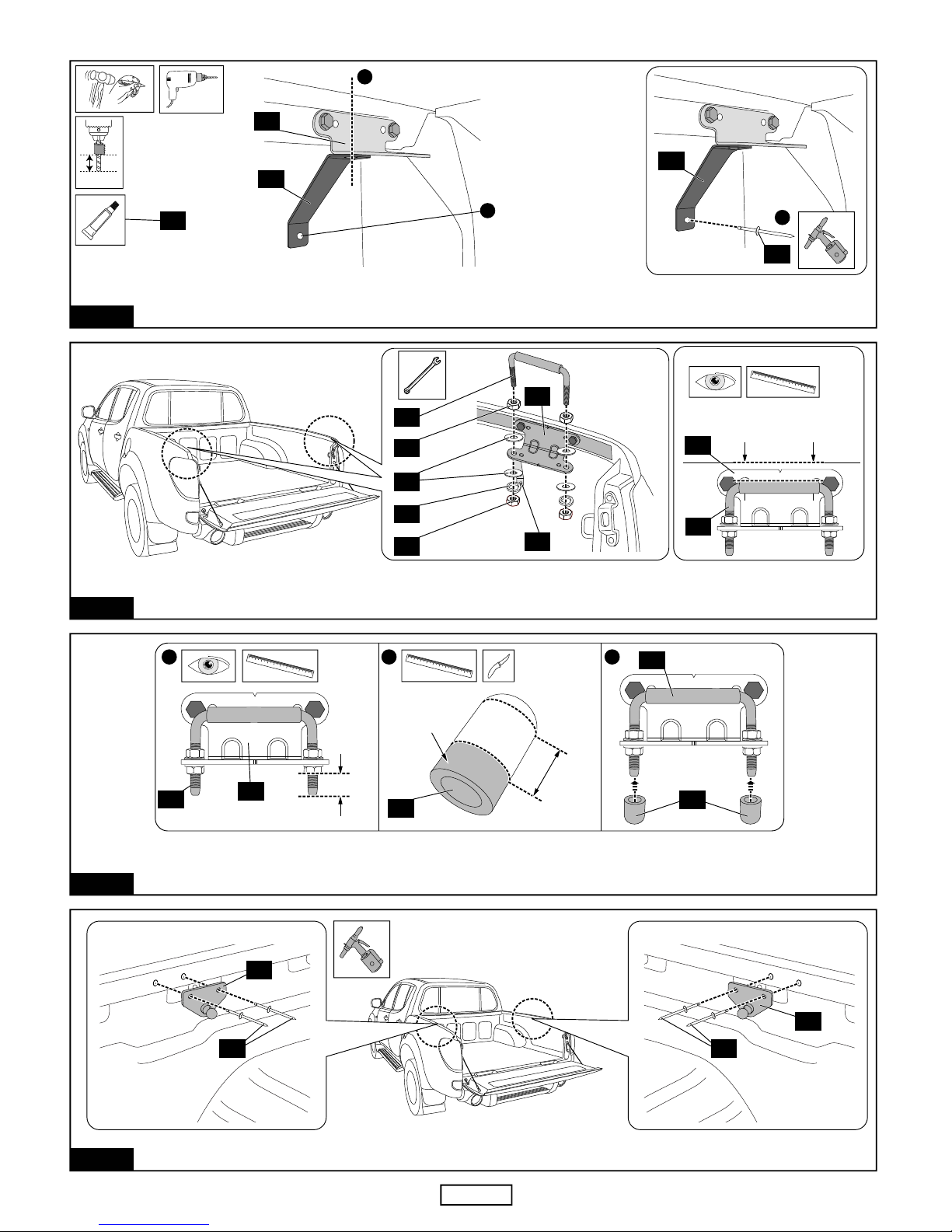
CLEAN HEADER RAIL AND HINGES (WHERE EXTRUSION WILL SIT) WITH ALCOHOL WIPES PROVIDED AND WIPE AWAY RESIDUE
WITH A DRY CLEAN CLOTH. PLACE THE EXTRUSION TAPE SEAL ALONG THE TOP OF THE HEADER RAIL WITH THE SEALING
LIP FACING TOWARDS THE TAILGATE. START THE EXTRUSION AT THE EDGE OF THE SIDE RAIL. IMPORTANT: POSITION
EXTRUSION AS CLOSE TO THE HEADER RAIL REAR RADIUS. RUB DOWN FIRMLY TO ENSURE MAXIMUM ADHESION.
18
24
11
18
12
REAR
NOTE: SEALING LIP
MUST FACE TAILGATE
REAR OF VEHICLE
START EXTRUSION
AT EDGE OF SIDE RAIL
POSITION EXTRUSION
AS CLOSE TO REAR RADIUS
18
12
11
HEADER
RAIL
Page 7

23
FIG. 20
TC0169eMITSUBISHI TRITON 3 PIECE TONNEAU COVER
29/10/10Page 7 of 13
PLACE THE CORNER PIECES OVER THE ENDS OF THE SPORTS BAR LEGS. LOOSELY ATTACH THEM TO THE SPORTS BAR USING
THE M6x40mm BOLTS, SPACERS AND LARGE M6 FLAT WASHERS AS SHOWN. DO NOT TIGHTEN FULLY AT THIS STAGE.
ISSUE05
FIG. 23
LOOSELY PRE-ASSEMBLE ONE (1) M8x50MM BOLT AND TWO (2) M8 HEX NUTS TO THE JACKING BRACKET AS SHOWN.
ALIGN JACKING BRACKET WITH PREVIOUSLY DRILLED HOLES, ENSURING BRACKET IS PARALLEL WITH TOP OF SIDE RAIL AND
SECURE WITH M6 BOLTS, M6 FLAT WASHERS, M6 SPRING WASHERS AND M6 NUTS AS SHOWN. TIGHTEN TO TORQUE 12Nm.
REPEAT FOR THE OTHER SIDE OF THE VEHICLE.
FIG. 22
CENTRE PUNCH THE TWO (2) HOLE POSITIONS AND DRILL Ø6MM HOLES. REPEAT FOR THE OTHER SIDE OF THE VEHICLE.
APPLY RUST INHIBITOR TO ALL THE DRILLED HOLES.
FIG. 21
ALIGN EDGE OF JACKING BRACKET TO EDGE OF GAS STRUT BRACKET ON SIDE RAIL AS SHOWN, 20MM DOWN FROM TOP OF
SIDE RAIL. MARK THE POSITION OF THE TWO (2) HOLES AS SHOWN. REPEAT FOR THE OTHER SIDE.
NO POWER TOOLS
20mm
ALIGN EDGE OF JACKING BRACKET
WITH EDGE OF GAS STRUT BRACKET
5
17
Ø6mm
20mm
APPLY RUST
INHIBITOR
1
2
1
CENTRE PUNCH,
THEN DRILL Ø6MM
HOLES
17
15
14
SIDE VIEW
8
9
20
17
7
2/3
19
19
27
2/3
26
26
Page 8

POSITION THE SPORTS BAR AND CORNER PIECES ON THE VEHICLE. ATTACH THE LEGS OF THE SPORTS BAR USING THE
RETAINED HARDWARE. NOTE: PUSH DOWN ON THE SPORTS BAR AND LIGHTLY TIGHTEN HARDWARE.
TC0169eMITSUBISHI TRITON 3 PIECE TONNEAU COVER
29/10/10Page 8 of 13
FIG. 24
ISSUE05
NO POWER TOOLS
SIDE VIEW
SPORTS BAR HARDWARE
SPORTS BAR
2
3
FIG. 27
FIG. 26
CLEAN THE PREVIOUSLY NOTED AREAS ON TUB WITH ALCOHOL WIPE PROVIDED AND WIPE AWAY RESIDUE WITH A DRY CLEAN
CLOTH. POSITION CLEAR ANTI-RUB PADS AT THESE AREAS ON THE TUB.
FIG. 25
NOTE THE AREA WHERE CORNER PIECE CONTACTS THE VEHICLE TUB AS SHOWN.
MARK THE EDGES AS SHOWN WITH A PENCIL OR NON-PERMANENT MARKER. REPEAT PROCESS FOR THE OTHER SIDE.
REMOVE SPORTSBAR AND CORNER PIECES FROM TUB.
RE-POSITION THE SPORTS BAR AND CORNER PIECES ON THE VEHICLE. ATTACH THE LEGS OF THE SPORTS BAR USING THE
RETAINED HARDWARE. NOTE: PUSH DOWN ON THE SPORTS BAR BEFORE TIGHTENING HARDWARE.
NO POWER TOOLS
SIDE VIEW
SPORTS BAR HARDWARE
SPORTS BAR
2
3
MARK THESE 2 EDGES
ON THE TUB
28
Page 9

TC0169eMITSUBISHI TRITON 3 PIECE TONNEAU COVER
29/10/10Page 9 of 13
FIG. 31
CHECK THAT THE SURFACES OF THE TONNEAU COVER AND CORNER PIECES ARE EVEN. ADJUST THE JACKING BOLTS
UNDERNEATH THE CORNER PIECES IF NECESSARY. ENSURE CLEARANCE BETWEEN CORNER PIECE AND TUB, ESPECIALLY
FRONT AND REAR, TO AVOID PAINT DAMAGE TO TUB.
ONCE IN THE CORRECT POSITION, LOCK THE M8 NUTS INTO
POSITION AGAINST THE BRACKET USING A SPANNER. REPEAT FOR THE OTHER SIDE OF THE VEHICLE.
IMPORTANT: TIGHTEN ALL CORNER PIECE M6 BOLTS TO 4Nm.
ISSUE05
NO POWER TOOLS
12/3
2/3
17
15
14
FIG. 28
FIG. 29
REMOVE INSPECTION COVER BY REMOVING SCRIVETS AND ROTATING COVER ANTI-CLOCKWISE. RELEASE PLASTIC RETAINER
CLIPS AND UNCLIP RODS AS SHOWN. LOOSEN THE FOUR (4) LATCH MECHANISM SCREWS, SO THE LATCH CAN MOVE FREELY
FOR TONNEAU ADJUSTMENT IN THE NEXT STEP.
INSPECTION
COVER
PLASTIC RETAINER
CLIPS
RODS
RELEASE PLASTIC
RETAINER CLIPS
REMOVE
INSPECTION
COVER
21
UNCLIP RODS FROM
PLASTIC RETAINER
CLIPS
LOOSEN SCREWS
3 4
SCREWS
FIG. 30
NEXT STEP
2
ENSURE
CLEARANCE
TO TUB
RUBBER SPACER
1
RE-TORQUE 5Nm
LOOSEN HINGE SCREWS
TO ADJUST TONNEAU
POSITION IF NECESSARY
2
IMPORTANT: THE TONNEAU COMES FITTED WITH TWO (2) RUBBER SPACERS TO ASSIST IN ALIGNMENT TO THE TUB.
CLOSE TONNEAU COVER AND CHECK THAT IT IS CENTRAL ON BED. LOOSEN HINGE SCREWS - DO NOT ADJUST HINGES WHILE
GAS STRUTS ARE CONNECTED. CHECK LH & RH LATCHES ARE ENGAGED. MOVE TONNEAU TO ENSURE EVEN CLEARANCE LHS
TO RHS BETWEEN TUB AND SPACERS. MOVE TONNEAU TO ENSURE FORE & AFT POSITION IS CORRECT BY ENSURING
CLEARANCE AT REAR OF TUB SIDE. RE-TIGHTEN (12) HINGE SCREWS WHILE TONNEAU IS IN CORRECT POSITION TO
TORQUE 5Nm. RE-TIGHTEN LATCHES WHILE TONNEAU IS IN CORRECT POSITION TO TORQUE 4Nm. IMPORTANT: ENSURE
TAILGATE REMAINS OPEN AND SPACERS ARE REMOVED AFTER ALIGNMENT IS COMPLETE.
OPEN TAILGATE. FIT THE TONNEAU COVER TO THE VEHICLE. SECURE THE HINGES USING THE HINGE PINS AS SHOWN.
IMPORTANT: ENSURE TAILGATE REMAINS OPEN. DO NOT REMOVE THE TWO (2) RUBBER SPACERS FROM THE TONNEAU
SIDES (AT THE REAR), THESE WILL BE REQUIRED FOR ALIGNMENT LATER ON.
2
1
1
RHS SHOWN
“CLICK”
3
RHS SHOWN
2
6
12
6
12
RUBBER
SPACER’S
Page 10

CLOSE TONNEAU AND INSPECT LOCKING MECHANISM. ENSURE LATCH HITS THE U BOLT CENTRALLY. IF IT DOES NOT, ADJUST THE U BOLT
ACCORDINGLY BY LOOSENING THE M6 NUTS AND MOVING THE U BOLT UP OR DOWN AS SHOWN. ONCE ADJUSTMENT IS COMPLETE, TIGHTEN
THE M6 NUTS. IMPORTANT: TONNEAU HAS 2 STAGE LOCKS. ENSURE TONNEAU ENGAGES WITH SECOND STAGE OF THE LATCH.
FIG. 33
TC0169eMITSUBISHI TRITON 3 PIECE TONNEAU COVER
29/10/10Page 10 of 13
ISSUE05
1
ATTACH GAS STRUTS. ENSURE THE NARROW END MOUNTS TO THE VEHICLE.
FIG. 32
ENSURE NARROW
END OF GAS STRUT
MOUNTS TO VEHICLE
TO REMOVE:
13
13
5
FIG. 34
OPEN TONNEAU AND ENGAGE LOCK BY PRESSING UPWARDS ON LATCH. ADJUST PULLRODS TO FIT INTO RETAINER CLIPS BY ROTATING THEM
CLOCKWISE TO SHORTEN OR ANTI-CLOCKWISE TO LENGTHEN. CLIP PULLRODS AND RETAINER CLIPS BACK INTO POSITION. TEST LOCK BY
PRESSING THE BUTTON ON TOP OF TONNEAU COVER. IF LATCH MECHANISM DOES NOT RELEASE, RETURN TO STEP 3 AND SHORTEN THE
PULLRODS. FINALLY, RE-CONFIRM THE OPEN-CLOSE-OPEN OPERATION OF TONNEAU WITH THE TAILGATE CLOSED. MAKE FURTHER
ADJUSTMENTS IF NECESSARY BY RETURNING TO FIGURE 29, 33 AND 34. FINALLY REPLACE INSPECTION COVER.
1
ENGAGE LOCK
LATCH MECHANISM
PRESS LATCH
UPWARDS
“CLICK”
2 4 6
TEST LOCKING MECHANISM
5
ROTATE PULLRODS
CLOCKWISE = SHORTEN
ANTI-CLOCKWISE = LENGTHEN
ADJUST LENGTH OF
PULLRODS BY ROTATION
3
RETAINER CLIPS
LOCK PLASTIC RETAINER
CLIPS BACK IN POSITION
REPLACE
INSPECTION COVER
INSPECTION
COVER
INCORRECT
INSPECT LATCH
ENGAGEMENT
CORRECT
2
ADJUST U-BOLT
USE A RULER TO ENSURE
U-BOLT REMAINS PARALLEL
TO LOCK STRIKER
3
TORQUE 10Nm
4
0mm102030405060708090
21
22
FIG. 35
NEXT STEP
2
1
RE-TORQUE 5Nm
LOOSEN HINGE SCREWS
TO ADJUST TONNEAU
POSITION IF NECESSARY
2
CLOSE TAILGATE AND TONNEAU COVER AND RE-CHECK CLEARANCES.
LOOSEN HINGE SCREWS AND ADJUST TONNEAU FORE & AFT IF REQUIRED.
DO NOT ADJUST HINGES WHILE GAS STRUTS ARE CONNECTED. RE-TIGHTEN HINGE SCREWS TO TORQUE 5Nm.
Page 11

TC0169eMITSUBISHI TRITON 3 PIECE TONNEAU COVER
29/10/10Page 11 of 13
ISSUE05
IMPORTANT:
HTC LATCH & STRIKER U-BOLT FREEPLAY, SHOULD BE CHECKED AND ADJUSTED
(AS PER STEPS 29, 33 & 34) AFTER 1500 Km’s (TO ACCOUNT FOR SEAL SETTLING).
KEY IDENTIFICATION CODE
XXXXX
MITSUBISHI MN TRITON ONWARDS 3 PIECE HARD TONNEAU COVER
Please write your key identification code in the boxes above and retain.
Replacement keys can be purchased from your local Mitsubishi dealer.
CLOSE TONNEAU AND CHECK CLOSING EFFORT WITH TAILGATE CLOSED. IF REQUIRED, ADJUST THE U BOLT ACCORDINGLY BY LOOSENING
THE M6 NUTS AND MOVING THE U BOLT UP OR DOWN. ONCE ADJUSTMENT IS COMPLETE, TIGHTEN THE M6 NUTS.
FIG. 36
1
ADJUST U-BOLT
USE A RULER TO ENSURE
U-BOLT REMAINS PARALLEL
TO LOCK STRIKER
TORQUE 10Nm
4
0mm102030405060708090
21
22
2
Page 12

OPEN TONNEAU COVER AND DETACH GAS STRUTS BY INSERTING A SMALL SCREW DRIVER AND ADJUSTING THE SPRING CLIP ON THE
STRUT AS SHOWN. NOTE: DO NOT REMOVE THE SPRING CLIP. ONLY A SMALL AMOUNT OF LEVERING IS REQUIRED TO DETACH.
TO REMOVE:
6
12
TC0169eMITSUBISHI TRITON 3 PIECE TONNEAU COVER
29/10/10Page 12 of 13
ISSUE05
REMOVAL OF TONNEAU COVER
FIG. 2
REMOVE HINGE PINS AND REMOVE THE TONNEAU COVER AS SHOWN.
FIG. 1
RHS SHOWN
2 3
RHS SHOWN
1
TO REPLACE THE TONNEAU COVER:
Reverse the sequence and the procedures of the two (2) Figures above.
13
13
5
6
12
Page 13

TC0169eMITSUBISHI TRITON 3 PIECE TONNEAU COVER
29/10/10Page 13 of 13
ISSUE05
1 25
10
16
Tonneau Cover
Qty - 1
PARTS IN MAIN CARTON
Lock Keys
(Attached to
Tonneau)
Qty - 2
3
RHS Corner
Piece
Qty - 1
2
LHS Corner
Piece
Qty - 1
Fitting Kit
(KIT031386)
Qty - 1
5 6 7 8 9
A
B
Gas Strut
Bracket
(CLIP2034-1)
Qty - 2
Hinge Pin
(MISC2267)
Qty - 2
M6x15 Hex
Head Bolt
(SCRW0633)
Qty - 8
M6 Flat
Washer
(WASH0153)
Qty - 24
M6Hex Nut
(NUTS0161)
Qty - 16
Pop Rivet
(FAST0505)
Qty - 12
11 12 13 14 15
21
Bottom Hinge
(CLIP1805-1)
Qty - 2
Hinge Retainer
Clip
(CLIP2673)
Qty - 2
Gas Strut
(STRT0003-2)
Qty - 2
M8x50 Hex
Head Bolt
(SCRW0789)
Qty - 2
M8Hex Nut
(NUTS0217)
Qty - 4
Jacking
Bracket
(CLIP2353-3)
Qty - 2
Extrusion
Tape Roll
(MISC2600)
Qty - 1
M6 Large
Flat Washer
(WASH0036)
Qty - 4
Striker U-Bolt
(LOCK0006)
Qty - 2
Lock Striker
Support Bracket
(CLIP2613PC)
Qty - 2
PARTS IN FITTING KIT (KIT031386)
17 18 19 20
M6 Spring
Washer
(WASH0103)
Qty - 12
PARTS CHECK SHEET MITSUBISHI TRITON 3 PIECE HARD TONNEAU COVER
4
Lock Striker
Bracket
(CLIP2499-PC)
Qty - 2
AUTOMOTIVE
SURFACE CLEANER
IMPREGNATED WITH 70% ISOPROPYL ALCOHOL
For use in cleaning painted metal,
glass and other vehicle surfaces.
For external use only.
Dispose of properly after use.
22 28
Rust Inhibitor
(MISC2776)
Qty - 1
Alcohol Wipe
(MISC0052)
Qty - 4
M6x40 Allen
Key Bolt
(SCRW0517)
Qty - 4
Anti-Rub Pad
(TAPE0011)
Qty - 2
Rubber
Thread Cap
(MISC2532)
Qty - 4
Fitting Instruction
(FIT-TC0169)
Qty - 1
23 24 26 27
Spacer
(MISC3095)
Qty - 4
Fitting
Instructions
 Loading...