

Page 1

General-Purpose AC Servo
MODEL
TM-RFM
TM-RG2M
TM-RU2M
DIRECT DRIVE MOTOR INSTRUCTION MANUAL
H
Page 2
Safety Instructions
Please read the instructions carefully before using the equipment.
To use the equipment correctly, do not attempt to install, operate, maintain or inspect the equipment until you
have read through this Instruction Manual and appended documents carefully. Do not use the equipment
until you have a full knowledge of the equipment, safety information and instructions.
In this Instruction Manual, the safety instruction levels are classified into "WARNING" and "CAUTION".
WARNING
CAUTION
Note that the CAUTION level may lead to a serious consequence according to conditions.
Please follow the instructions of both levels because they are important to personnel safety.
What must not be done and what must be done are indicated by the following diagrammatic symbols.
Indicates that incorrect handling may cause hazardous conditions,
resulting in death or severe injury.
Indicates that incorrect handling may cause hazardous conditions,
resulting in medium or slight injury to personnel or may cause physical
damage.
Indicates what must not be done. For example, "No Fire" is indicated by
Indicates what must be done. For example, grounding is indicated by
In this Instruction Manual, instructions at a lower level than the above, instructions for other functions, and so
on are classified into "POINT".
After reading this Instruction Manual, keep it accessible to the operator.
.
.
A - 1
Page 3
1. To prevent electric shock, note the following
WARNING
Before wiring and inspections, turn off the power and wait for 15 minutes or more until the charge lamp
turns off. Otherwise, an electric shock may occur. In addition, when confirming whether the charge lamp
is off or not, always confirm it from the front of the servo amplifier. Then, confirm that the voltage
between P+ and N- is safe with a voltage tester and others.
Ground the servo amplifier and direct drive motor securely.
Any person who is involved in wiring and inspection should be fully competent to do the work.
Do not attempt to wire the servo amplifier and direct drive motor until they have been installed.
Otherwise, it may cause an electric shock.
The cables should not be damaged, stressed, loaded, or pinched. Otherwise, it may cause an electric
shock.
To avoid an electric shock, insulate the connections of the power supply terminals.
2. To prevent fire, note the following
CAUTION
Install the servo amplifier, direct drive motor, and regenerative resistor on incombustible material.
Installing them directly or close to combustibles will lead to a fire or smoke generation.
Provide adequate protection to prevent screws and other conductive matter, oil and other combustible
matter from entering the servo amplifier and direct drive motor.
3. To prevent injury, note the following
CAUTION
Only the power/signal specified in the Instruction Manual should be applied to each terminal. Otherwise,
it may cause an electric shock, fire, injury, etc.
Connect cables to the correct terminals. Otherwise, a burst, damage, etc. may occur.
Ensure that polarity (+/-) is correct. Otherwise, a burst, damage, etc. may occur.
The servo amplifier heat sink, regenerative resistor, direct drive motor, etc. may be hot while power is on
or for some time after power-off. Take safety measures, e.g. provide covers, to avoid accidentally
touching the parts (cables, etc.) by hand.
During operation, never touch the rotor of the direct drive motor. Otherwise, it may cause injury.
A - 2
Page 4
4. Additional instructions
The following instructions should also be fully noted. Incorrect handling may cause a malfunction, injury,
electric shock, fire, etc.
(1) Transportation and installation
CAUTION
Transport the products correctly according to their mass.
Stacking in excess of the specified number of product packages is not allowed.
Do not hold the cables, rotor, encoder, or connector when carrying the direct drive motor. Otherwise, it
may drop.
Install the servo amplifier and the direct drive motor in a load-bearing place in accordance with the
Instruction Manual.
Do not get on or put heavy load on the equipment. Otherwise, it may cause injury.
The equipment must be installed in the specified direction.
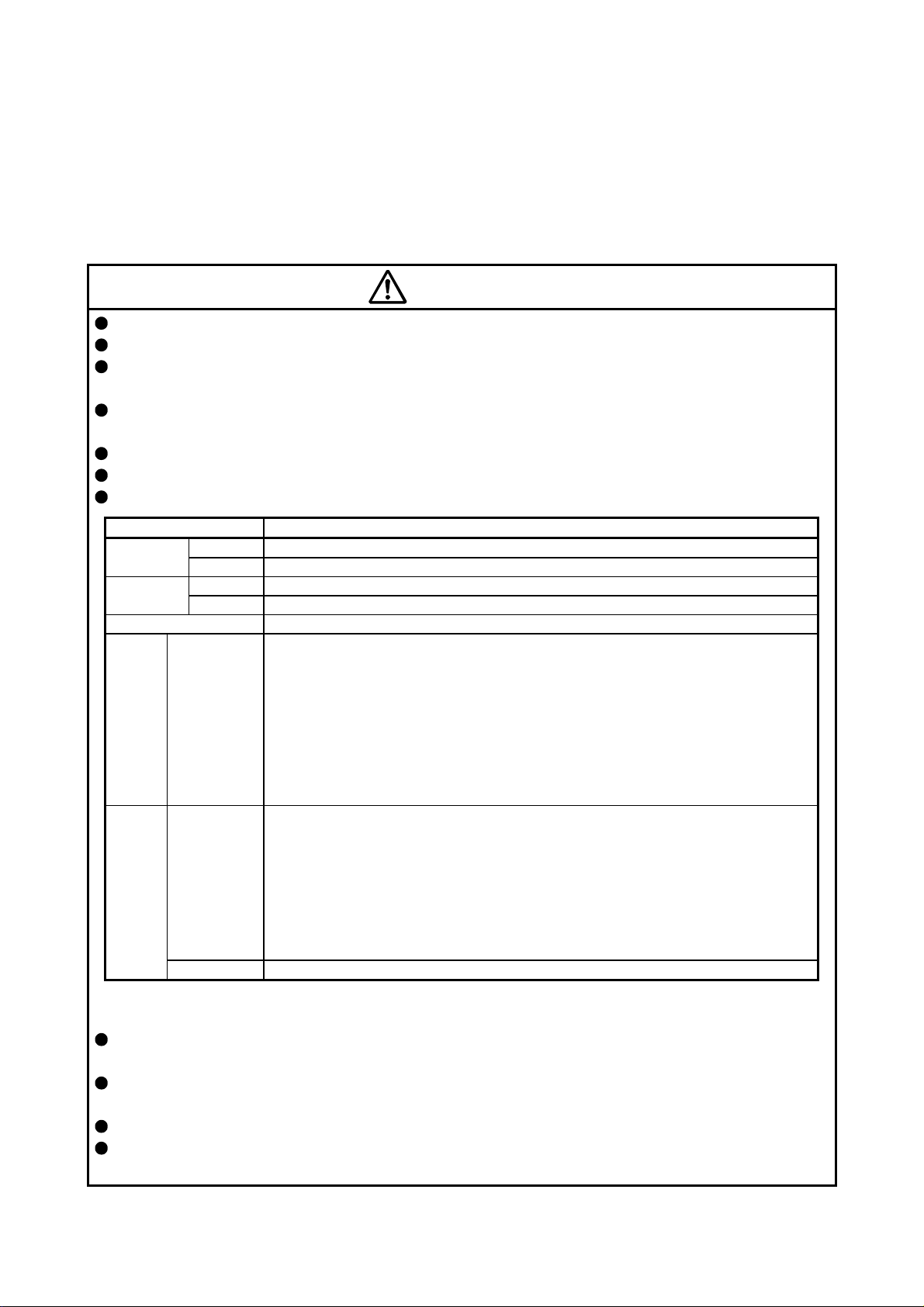
When you keep or use the equipment, please fulfill the following environment.
Ambient
temperature
Ambient
humidity
Altitude
Vibration
resistance
Note. Contact your local sales office for the altitude for options.
Securely fix the direct drive motor to the machine. If being attached insecurely, the motor may come off
during operation.
Do not install or operate a servo amplifier or direct drive motor, which has been damaged or has any
parts missing.
Do not drop or strike the direct drive motor. Otherwise, it may cause injury, malfunction, etc.
Take safety measures, e.g. provide covers, to prevent accidental access to the rotor of the direct drive
motor during operation.
Item Environment
Operation 0 °C to 40 °C (non-freezing)
Storage -15 °C to 70 °C (non-freezing)
Operation 10 %RH to 80 %RH (non-condensing)
Storage 10 %RH to 90 %RH (non-condensing)
Ambience Indoors (no direct sunlight); no corrosive gas, inflammable gas, oil mist, dust, and dirt
TM-RFM_J10
TM-RFM_C20
TM-RFM_E20
TM-RFM_G20
TM-RG2M_C30
TM-RG2M_E30
TM-RG2M_G30
TM-RU2M_C30
TM-RU2M_E30
TM-RU2M_G30
TM-RFM_C20
TM-RFM_E20
TM-RFM_G20
TM-RG2M_C30
TM-RG2M_E30
TM-RG2M_G30
TM-RU2M_C30
TM-RU2M_E30
TM-RU2M_G30
TM-RFM_J10 X, Y: 24.5 m/s2
Max. 2000 m above sea level (Note)
X, Y: 49 m/s
2
A - 3
Page 5
CAUTION
Do not apply shocks, e.g. hit with a hammer, when coupling the rotor of the direct drive motor. Otherwise,
the encoder may malfunction.
Do not subject the rotor of the direct drive motor to more than the permissible load. Otherwise, the rotor
may break.
When the product has been stored for an extended period of time, contact your local sales office.
When handling the direct drive motor, be careful about the edged parts such as corners of the direct
drive motor.
Do not strike the connector. Otherwise, it may cause a connection failure, malfunction, etc.
Be sure to check the vibration level with the direct drive motor mounted on the machine. A great vibration
may cause the early damage of a bearing and encoder. The great vibration may also cause the poor
connector connection or bolt looseness.
For the gain adjustment at the equipment startup, check the torque waveform and the speed waveform
with a measurement device to check that no vibration occurs. If the vibration occurs due to high gain, the
vibration may cause the early damage of the direct drive motor.
To prevent a fire or injury in case of an earthquake or other natural disasters, securely install, mount, and
wire the servo motor in accordance with the Instruction Manual.
(2) Wiring
CAUTION
Wire the equipment correctly and securely. Otherwise, the direct drive motor may operate unexpectedly.
Make sure to connect the cables and connectors by using the fixing screws and the locking mechanism.
Otherwise, the cables and connectors may be disconnected during operation.
Do not install a power capacitor, surge killer, or radio noise filter (FR-BIF option) on the power wire of the
direct drive motor.
To avoid a malfunction, connect the power phases (U/V/W) of the servo amplifier and the direct drive
motor correctly.
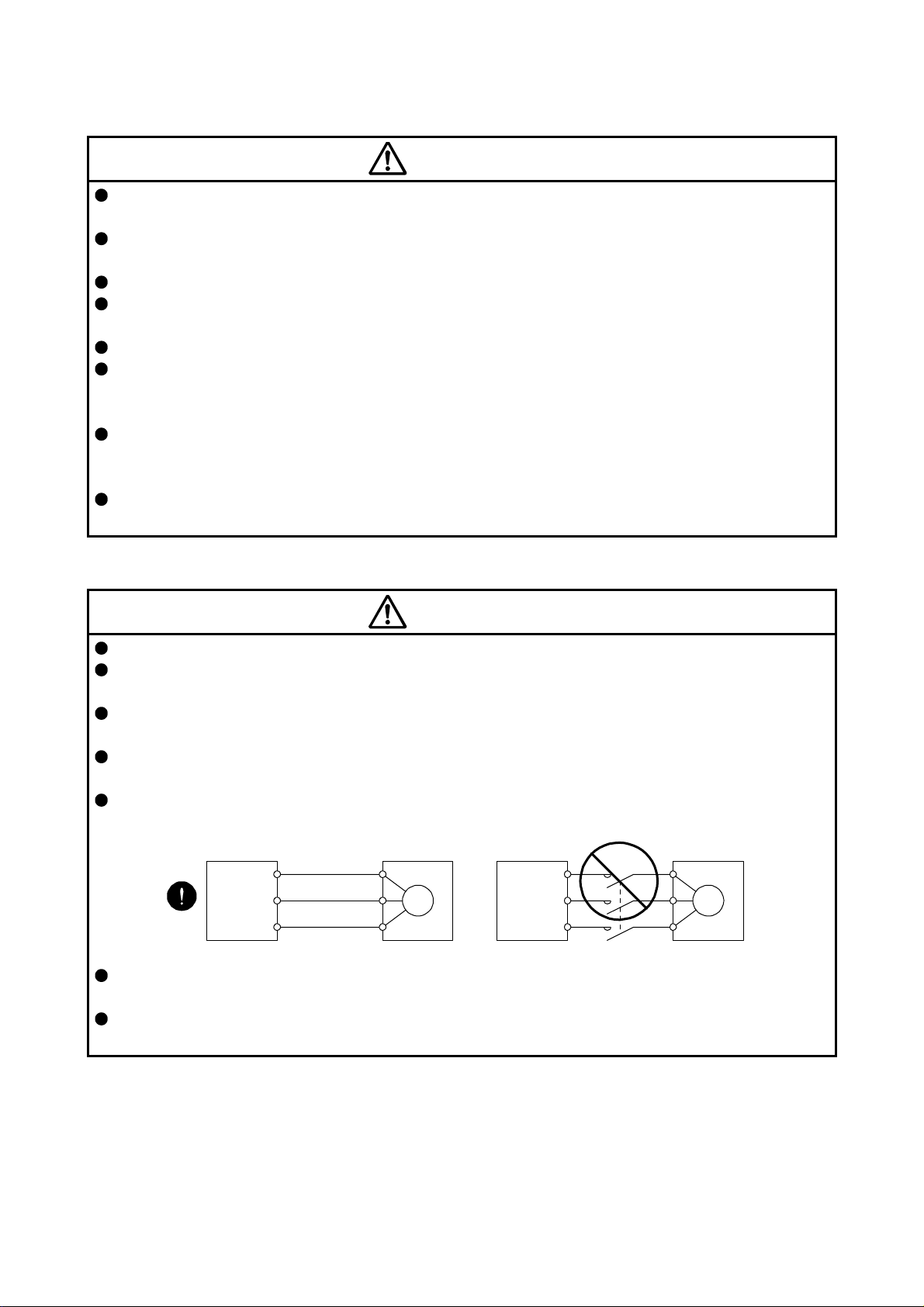
Connect the servo amplifier power output (U/V/W) to the direct drive motor power input (U/V/W) directly.
Do not let a magnetic contactor, etc. intervene. Otherwise, it may cause a malfunction.
Servo amplifier
U
V
W
Direct drive motor
U
V
M
W
Servo amplifier
U
V
W
Do not connect AC power supply directly to the direct drive motor. Otherwise, it may cause a
malfunction.
When the cable is not tightened enough to the terminal block, the cable or terminal block may generate
heat because of the poor contact. Be sure to tighten the cable with specified torque.
Direct drive motor
U
V
M
W
A - 4
Page 6
(3) Test run and adjustment
CAUTION
Before operation, check the parameter settings. Improper settings may cause some machines to operate
unexpectedly.
Never make a drastic change to the parameter values as doing so will make the operation unstable.
(4) Usage
CAUTION
Provide an external emergency stop circuit to ensure that operation can be stopped and power switched
off immediately.
For equipment in which the moving part of the machine may collide against the load side, install a limit
switch or stopper to the end of the moving part. The machine may be damaged due to a collision.
Do not disassemble, repair, or modify the product. Otherwise, it may cause an electric shock, fire, injury,
etc. Disassembled, repaired, and/or modified products are not covered under warranty.
Use the direct drive motor with the specified servo amplifier.
Wire options and peripheral equipment, etc. correctly in the specified combination. Otherwise, it may
cause an electric shock, fire, injury, etc.
If the dynamic brake is activated at power-off, alarm occurrence, etc., do not rotate the servo motor by an
external force. Otherwise, it may cause a fire.
(5) Corrective actions
CAUTION
When it is assumed that a hazardous condition may occur due to a stop or product malfunction, use a
motor with an external brake to prevent the condition.
When any alarm has occurred, eliminate its cause, ensure safety, and deactivate the alarm before
restarting operation.
Provide an adequate protection to prevent unexpected restart after an instantaneous power failure.
After an earthquake or other natural disasters, ensure safety by checking the conditions of the
installation, mounting, wiring, and equipment before switching the power on to prevent an electric shock,
injury, or fire.
A - 5
Page 7
(6) Storage
CAUTION
Note the followings when storing the direct drive motor for an extended period of time (guideline: three
months or more).
Always store the direct drive motor indoors in a clean and dry place.
If it is stored in a dusty or damp place, make adequate provision, e.g. cover the whole product.
If the insulation resistance of the winding decreases, check how to store the equipment.
Though the motor is rust-proofed before shipment using paint or rust prevention oil, rust may be
produced depending on the storage conditions or storage period.
If the direct drive is to be stored for longer than six months, apply rust prevention oil again especially to
the machine processing surfaces of the rotor, etc.
Before using the product after storage for an extended period of time, hand-turn the direct drive motor
rotor (output shaft) to confirm that nothing is wrong with the direct drive motor.
When the product has been stored for an extended period of time, contact your local sales office.
(7) General instruction
To illustrate details, the equipment in the diagrams of this Instruction Manual may have been drawn
without covers and safety guards. When the equipment is operated, the covers and safety guards must
be installed as specified. Operation must be performed in accordance with this Specifications and
Instruction Manual.
DISPOSAL OF WASTE
Please dispose a direct drive motor and other options according to your local laws and regulations.
«About the manual»
This Instruction Manual is required if you use this direct drive motor for the first time. Ensure to keep this
manual accessible to use the direct drive motor safely.
«Cables used for wiring»
The wiring cables mentioned in this Instruction Manual are selected based on the ambient temperature of
40 °C.
«U.S. customary units»
U.S. customary units are not shown in this manual. Convert the values if necessary according to the
following table.
Mass 1 [kg] 2.2046 [lb]
Length 1 [mm] 0.03937 [inch]
Torque 1 [N•m] 141.6 [oz•inch]
Moment of inertia 1 [(× 10-4 kg•m2)] 5.4675 [oz•inch2]
Load (thrust load/axial load) 1 [N] 0.2248 [lbf]
Temperature N [°C] × 9/5 + 32 N [°F]
Quantity SI (metric) unit U.S. customary unit
A - 6
Page 8

CONTENTS
1. INTRODUCTION 1 - 1 to 1 - 2
1.1 Rating plate ...................................................................................................................................... 1 - 1
1.2 Parts identification ............................................................................................................................ 1 - 1
2. INSTALLATION 2 - 1 to 2 - 8
2.1 Equipment configuration .................................................................................................................. 2 - 2
2.2 Mounting direction............................................................................................................................ 2 - 3
2.3 Load mounting/dismounting precautions ......................................................................................... 2 - 3
2.4 Permissible load for the rotor ........................................................................................................... 2 - 3
2.5 Protection from oil and water ........................................................................................................... 2 - 4
2.6 Inspection items ............................................................................................................................... 2 - 5
2.7 Parts having service life ................................................................................................................... 2 - 5
2.8 Machine accuracies ......................................................................................................................... 2 - 6
2.9 Flange size ....................................................................................................................................... 2 - 6
2.10 Restrictions when using this product at altitudes exceeding 1000 m and up to 2000 m
above sea level .............................................................................................................................. 2 - 7
2.11 Magnetic shielding ......................................................................................................................... 2 - 7
3. CONNECTORS USED FOR DIRECT DRIVE MOTOR WIRING 3 - 1 to 3 - 4
3.1 Selection of connectors ................................................................................................................... 3 - 1
3.2 Wiring connectors (connector configurations A/B/C/D/E/F) ............................................................ 3 - 2
4. CONNECTOR DIMENSIONS 4 - 1 to 4 - 4
5. CONNECTION OF SERVO AMPLIFIER AND DIRECT DRIVE MOTOR 5 - 1 to 5 - 8
5.1 Connection instructions ................................................................................................................... 5 - 2
5.2 Direct drive motor power cable wiring diagram ............................................................................... 5 - 2
5.3 Selection example of wires .............................................................................................................. 5 - 3
5.4 Servo amplifier terminal section ....................................................................................................... 5 - 4
6. WIRING OPTION 6 - 1 to 6 -10
6.1 Connector set ................................................................................................................................... 6 - 1
6.1.1 Combinations of connector set ................................................................................................. 6 - 2
6.1.2 Connector list ............................................................................................................................ 6 - 3
6.2 Encoder connector set ..................................................................................................................... 6 - 4
6.2.1 MR-J3DDCNS ........................................................................................................................... 6 - 4
6.2.2 MR-J3DDSPS ........................................................................................................................... 6 - 5
6.2.3 Combinations for the encoder cable ......................................................................................... 6 - 5
6.2.4 Fabrication of the encoder cable ............................................................................................... 6 - 6
6.3 Absolute position storage unit MR-BTAS01 .................................................................................... 6 - 9
1
Page 9

7. TM-RFM SERIES 7 - 1 to 7 -12
7.1 Model code definition ....................................................................................................................... 7 - 1
7.2 Combinations of servo amplifier and direct drive motor .................................................................. 7 - 2
7.3 Specification list ............................................................................................................................... 7 - 3
7.4 Torque characteristics ..................................................................................................................... 7 - 6
7.5 Dimensions ...................................................................................................................................... 7 - 7
8. TM-RG2M SERIES/TM-RU2M SERIES 8 - 1 to 8 -10
8.1 Model designation ............................................................................................................................ 8 - 1
8.2 Combinations of servo amplifier and direct drive motor .................................................................. 8 - 2
8.3 Specification list ............................................................................................................................... 8 - 3
8.4 Torque characteristics ..................................................................................................................... 8 - 5
8.5 Mounting method ............................................................................................................................. 8 - 5
8.6 Dimensions ...................................................................................................................................... 8 - 6
APPENDIX App. - 1 to App. - 7
App. 1 Selection example of direct drive motor ............................................................................... App. - 1
App. 2 Manufacturer list ................................................................................................................... App. - 3
App. 3 Crimping connector for CNP3_ ............................................................................................ App. - 3
App. 4 Fabrication of the encoder cable .......................................................................................... App. - 4
App. 5 Compliance with the CE marking ......................................................................................... App. - 5
App. 6 Compliance with UL/CSA standard ...................................................................................... App. - 6
2
Page 10
1. INTRODUCTION
1. INTRODUCTION
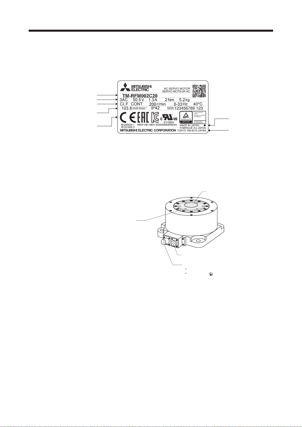
1.1 Rating plate
The following shows an example of rating plate for explanation of each item.
Input power, rated torque, and mass
Model
Insulation class, rated speed, and
maximum ambient temperature
Induced voltage constant, IP rating,
and serial number (Note 1)
(Note 2)
Note 1. Production year and month of the direct drive motor are indicated in a serial number on the rating plate.
The year and month are indicated by the last two digits of the year and one digit of the month [1 to 9, X (10), Y (11), and Z
(12)].
For January 2012, the Serial No. is like, "SER. _ _ _ _ _ _ _ _ _ 121".
2. Products approved by Certification Bodies are marked. The marks depends on the Certification Bodies.
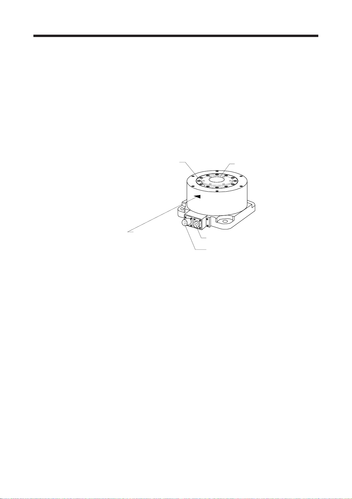
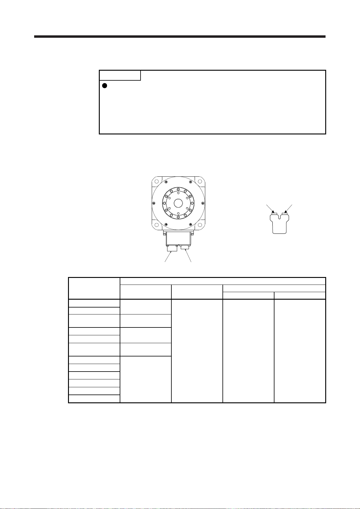
1.2 Parts identification
Rotor (output shaft)
Z-phase mark
Conforming standards,
and Country of origin
Manufacturer
Encoder connector
Power supply connector
Power supply (U/V/W)
Grounding ( )
1 - 1
Page 11

1. INTRODUCTION
MEMO
1 - 2
Page 12
2. INSTALLATION
2. INSTALLATION
WARNING
CAUTION
To prevent electric shock, ground each equipment securely.
Stacking in excess of the specified number of product packages is not allowed.
Install the direct drive motor on incombustible material. Installing them directly or
close to combustibles will lead to smoke or a fire.
Install the servo amplifier and the direct drive motor in a load-bearing place in
accordance with the Instruction Manual.
Do not get on or put heavy load on the equipment. Otherwise, it may cause injury.
Use the equipment within the specified environment. For the environment, refer to
section 7.3.
Do not drop or strike the direct drive motor as it is precision equipment.
Do not install or operate a direct drive motor, which has been damaged or has
any parts missing.
Do not hold the cables, rotor, encoder, or connector when carrying the direct drive
motor. Otherwise, it may drop.
Securely fix the direct drive motor to the machine. If being attached insecurely,
the motor may come off during operation, leading to injury.
Do not apply shocks, e.g. hit with a hammer, when coupling the rotor of the direct
drive motor. Otherwise, the encoder may malfunction.
When coupling a load to the direct drive motor, make sure to align and center the
load on the motor flange rabbet. Particularly, when a rigid coupling is used, even
a slight center deviation may reduce position accuracy or damage the rotor.
Balance the load to the extent possible. Not doing so can cause vibration during
direct drive motor operation or damage the bearings and encoder.
Take safety measures, e.g. provide covers, to prevent accidental access to the
rotor of the direct drive motor during operation.
Do not subject the rotor of the direct drive motor to more than the permissible
load. Otherwise, the rotor may break, leading to injury.
When the product has been stored for an extended period of time, contact your
local sales office.
Be sure to check the vibration level with the direct drive motor mounted on the
machine. A great vibration may cause the early damage of a bearing and
encoder. The great vibration may also cause the poor connector connection or
bolt looseness.
For the gain adjustment at the equipment startup, check the torque waveform and
the speed waveform with a measurement device to check that no vibration
occurs. If the vibration occurs due to high gain, the vibration may cause the early
damage of the direct drive motor.
Do not use the direct drive motor where the shaft-through portion may be subject
to pressure (e.g. compressed air). Applying air pressure to the inside of the direct
drive motor may cause a malfunction.
2 - 1
Page 13
2. INSTALLATION
2.1 Equipment configuration
The following shows the configuration of a direct drive motor. When using the direct drive motor, note the
following.
(1) Minimum oscillation angle
If the direct drive motor rotates repeatedly by a small angle (by 70 or less), make the direct drive motor
rotate by 90 or more at least once a day in order to keep the bearing lubricated.
(2) Z-phase position
A Z-phase pulse turns on (Z-phase mark passing) when the Z-phase mark on the rotor end of the direct
drive motor passes over the connector area. Keep the Z-phase position visible even after the direct drive
motor is installed to a machine.
Z-phase mark
Rotor (output shaft)
A Z-phase pulse turns
on when the Z-phase
mark passes over
the connector area.
Encoder connector
Power supply connector
(3) Precautions for Z-phase mark passing
After power on, the Z-phase mark of the direct drive motor must pass the connector area once. In a
system which prevents the direct drive motor from making a full rotation, install the direct drive motor in a
position where the Z-phase mark can pass over the connector area.
(4) Vertical axis (lift)
For the system where the unbalanced torque occurs, such as a vertical axis system (lift), use the direct
drive motor in the absolute position detection system. In the absolute position detection system, the
absolute position is established when the Z-phase mark passes the connector area once. Therefore, at
system startup, make the Z-phase mark pass over the connector area, and switch the servo amplifier's
power supply from off to on.
If the direct drive motor can be rotated manually, make the Z-phase mark pass over the connector area
while only the servo amplifier's control circuit power supply is on. After that, switch the servo amplifier's
power supply from off to on.
If the direct drive motor cannot be rotated manually, detect the magnetic poles while the torque is
balanced, then run the direct drive motor in the test mode to make its Z-phase mark pass over the
connector area. After that, switch the servo amplifier's power supply from off to on. After the Z-phase
mark passes over the connector area once, magnetic pole detection is not required.
2 - 2
Page 14

2. INSTALLATION
2.2 Mounting direction
The following table indicates the mounting direction of the direct drive motor.
2.3 Load mounting/dismounting precautions
POINT
During assembling, the rotor must not be hammered. Otherwise, the encoder
may malfunction.
Direct drive motor series Mounting direction
TM-RFM
TM-RG2M
TM-RU2M
All directions
(1) The direction of the encoder on the direct drive motor cannot be changed.
(2) When mounting the direct drive motor, use spring washers, etc. and fully tighten the bolts so that they do
not become loose due to vibration.
2.4 Permissible load for the rotor
Because the rigid coupling may damage the rotor, make sure to align and center
CAUTION
the load on the rotor.
For the permissible rotor load specific to the direct drive motor, refer to section 7.3.
(1) When coupling a load to the direct drive motor, the load applied to the rotor must be within the
permissible load.
(2) The load, which exceeds the permissible load, can cause the bearing life to reduce and the rotor to
break.
(3) The load indicated in this section is static load in a single direction and does not include eccentric load.
Make eccentric load as small as possible. Not doing so can cause the direct drive motor to be damaged.
2 - 3
Page 15
2. INSTALLATION
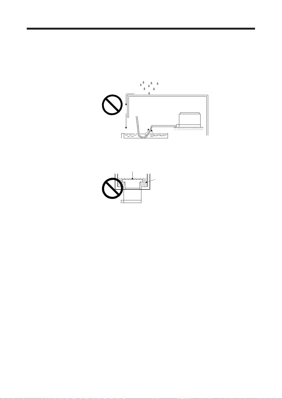
2.5 Protection from oil and water
Provide adequate protection to prevent foreign matter, such as oil and water, from entering the rotor of the
direct drive motor. When mounting the direct drive motor, consider the items in this section.
(1) Do not use the direct drive motor with its cable soaked in oil or water.
Cover
Direct drive motor
Oil/water pool
Capillary action
Provide measures so that the direct drive motor is not exposed to oil and water entering from the
machine side, rotating table, etc.
Rotary table, etc.
Lubricating oil
Direct drive motor
(3) If liquid such as coolant drops on the direct drive motor, the sealant, packing, cable and others may be
affected depending on the liquid type.
(4) In the environment where the direct drive motor is exposed to oil mist, steam, oil, water, grease, and/or
the like, a standard specification direct drive motor cannot be used. Provide measures to prevent dust
and/or water on the machine side.
2 - 4
Page 16
2. INSTALLATION
2.6 Inspection items
Before starting maintenance and/or inspection, turn off the power and wait for 15
minutes or more until the charge lamp turns off. Then, confirm that the voltage
between P+ and N- is safe with a voltage tester and others. Otherwise, an electric
WARNING
CAUTION
It is recommended that the following points to be periodically checked.
(1) Check the bearings, etc. for unusual noise.
(2) Check the cables and the like for scratches or cracks. Especially when the junction cable is movable,
perform periodic inspection according to operating conditions.
(3) Check the power connector and encoder connector connections for looseness.
2.7 Parts having service life
shock may occur. In addition, when confirming whether the charge lamp is off or
not, always confirm it from the front of the servo amplifier.
To avoid an electric shock, only qualified personnel should attempt inspections.
For repair, contact your local sales office.
Do not perform insulation resistance test on the direct drive motor. Otherwise, it
may cause a malfunction.
Do not disassemble and/or repair the equipment on customer side.
Service life of the following parts is listed below. However, the service life varies depending on operation and
environment. If any fault is found in the parts, they must be replaced immediately regardless of their service
life. For parts replacement, contact your local sales office.
Part name Life guideline Remark
Bearings
Encoder
Absolute position
storage unit
(option)
20,000 hours to
30,000 hours
20,000 hours to
30,000 hours
20,000 hours to
30,000 hours
The Guideline of Life field gives the reference
time.
If any fault is found before this time is
reached, the part must be changed.
When the motor is run at rated speed under rated load, bearings should be exchanged in 20,000 to
30,000 hours as a guideline. This differs on the operating conditions. The bearings must also be changed if
unusual noise or vibration is found during inspection.
2 - 5
Page 17
2. INSTALLATION
2.8 Machine accuracies
The following table indicates the machine accuracies of the rotor (output shaft) and the mounting area of the
direct drive motor (except special products).
Item
Runout of mounting surface to rotor
(output shaft)
Runout of fitting outer diameter of
mounting surface
Runout of rotor (output shaft) c 0.04
Runout of rotor (output shaft) end d 0.02
Reference diagram
a
A
d
A
Measuring
position
a 0.05
b 0.07
Accuracy [mm]
_
_
b
A
c
2.9 Flange size
The rated torque of the direct drive motor indicates the continuous permissible torque value that can be
generated when the motor is mounted on the aluminum flange specified in this table and used in the
environment of 0 °C to 40 °C ambient temperature.
Flange size
[mm]
TM-RG2M002C30
TM-RU2M002C30
400 × 400 × 20 TM-RFM002C20
TM-RFM004C20
TM-RFM006C20
TM-RG2M004E30
TM-RU2M004E30
550 × 550 × 35 TM-RFM006E20
TM-RFM012E20
TM-RFM018E20
TM-RG2M009G30
TM-RU2M009G30
650 × 650 × 35 TM-RFM012G20
TM-RFM048G20
TM-RFM072G20
750 × 750 × 45
950 × 950 × 50 TM-RFM240J10
Direct drive motor
TM-RFM040J10
TM-RFM120J10
2 - 6
Page 18

2. INSTALLATION
2.10 Restrictions when using this product at altitudes exceeding 1000 m and up to 2000 m above sea level
As heat dissipation effects decrease in proportion to the decrease in air density, use the product within the
effective load ratio and regenerative load ratio shown in the following figure.
[%]
100
95
Effective load ratio
0
0
Regenerative load ratio
Altitude
2.11 Magnetic shielding
Do not place the direct drive motor near magnetic sources, such as a magnet. If it is unavoidable, block the
magnetic force by installing a shielding plate, etc.
[m]
20001000
2 - 7
Page 19

2. INSTALLATION
MEMO
2 - 8
Page 20
3. CONNECTORS USED FOR DIRECT DRIVE MOTOR WIRING
3. CONNECTORS USED FOR DIRECT DRIVE MOTOR WIRING
POINT
The IP rating indicated is the connector's protection against ingress of dust and
water when the connector is connected to a servo amplifier, direct drive motor,
or absolute position storage unit.
If the IP rating of the connector, servo amplifier, direct drive motor and absolute
position storage unit vary, the overall IP rating depends on the lowest IP rating of
all components.
3.1 Selection of connectors
Use the connector configuration products given in the table as the connectors for connection with the direct
drive motor. Refer to section 3.2 for the compatible connector configuration products.
Servo amplifier
side connector
Absolute position
Encoder side
connector
storage unit
MR-BTAS01
Power supply connector Encoder connector
Direct drive motor
TM-RFM_C20
TM-RFM_E20
TM-RFM_G20
TM-RFM040J10
TM-RFM120J10
TM-RFM240J10
TM-RG2M002C30
TM-RU2M002C30
TM-RG2M004E30
TM-RU2M004E30
TM-RG2M009G30
TM-RU2M009G30
For power supply For encoder
Wiring connector
Absolute position storage unit (option) (Note)
Servo amplifier side Encoder side
Connector
configuration B
Connector
configuration C
Connector
configuration D
Connector
configuration E
Connector
configuration B
Connector
configuration A
Connector
configuration A
Connector
configuration F
Note. Used in the absolute position detection system
3 - 1
Page 21
3. CONNECTORS USED FOR DIRECT DRIVE MOTOR WIRING
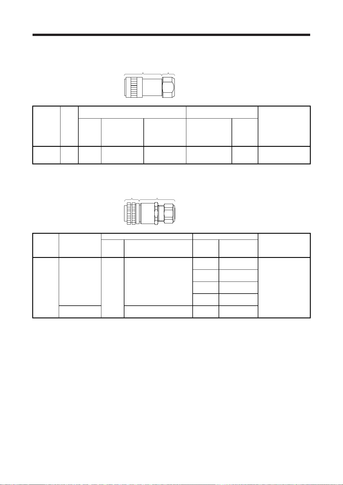
3.2 Wiring connectors (connector configurations A/B/C/D/E/F)
Cord
Plug
clamp
Plug (Hirose Electric)
Connector
configuration
Feature
Type Plug Cord clamp Model
A IP67 Straight RM15WTPZK-12S JR13WCCA-8(72)
Note 1. The connector to be mated.
2. Purchase from Toa Electric Industrial Co. Ltd., Nagoya Branch
Cable
Plug
clamp
Plug (DDK) Cable clamp
Connector
configuration
B
Feature
IP67
EN compliant
8.3 to 11.3
General environment
(Note 1)
Type Model
4 to 8
CE05-6A14S-2SD-D
Straight
Applicable wire size: AWG 22 to 16
D/MS3106B14S-2S
Applicable wire size: AWG 22 to 16
Note 1. Not comply with EN.
2. The connector to be mated.
Recommended cable
(Bando Densen)
20276
VSVPAWG#23×6P
KB-0492 (Note 2)
Cable OD
[mm]
(reference)
8 to 12
5 to 8.3
7.9 or less
(bushing ID)
Cable OD
[mm]
(reference)
8.2 RM15WTRZB-12P(72)
Model
ACS-08RL-MS14F
(Nippon Flex)
ACS-12RL-MS14F
(Nippon Flex)
YSO14-5 to 8
(Daiwa Dengyo)
YSO14-9 to 11
(Daiwa Dengyo)
D/MS3057-6A
Direct drive motor encoder
connector
or
Absolute position storage
unit connector
(servo amplifier side)
(Note 1)
Direct drive motor power
connector (Note 2)
CE05-2A14S-2PD-D
3 - 2
Page 22
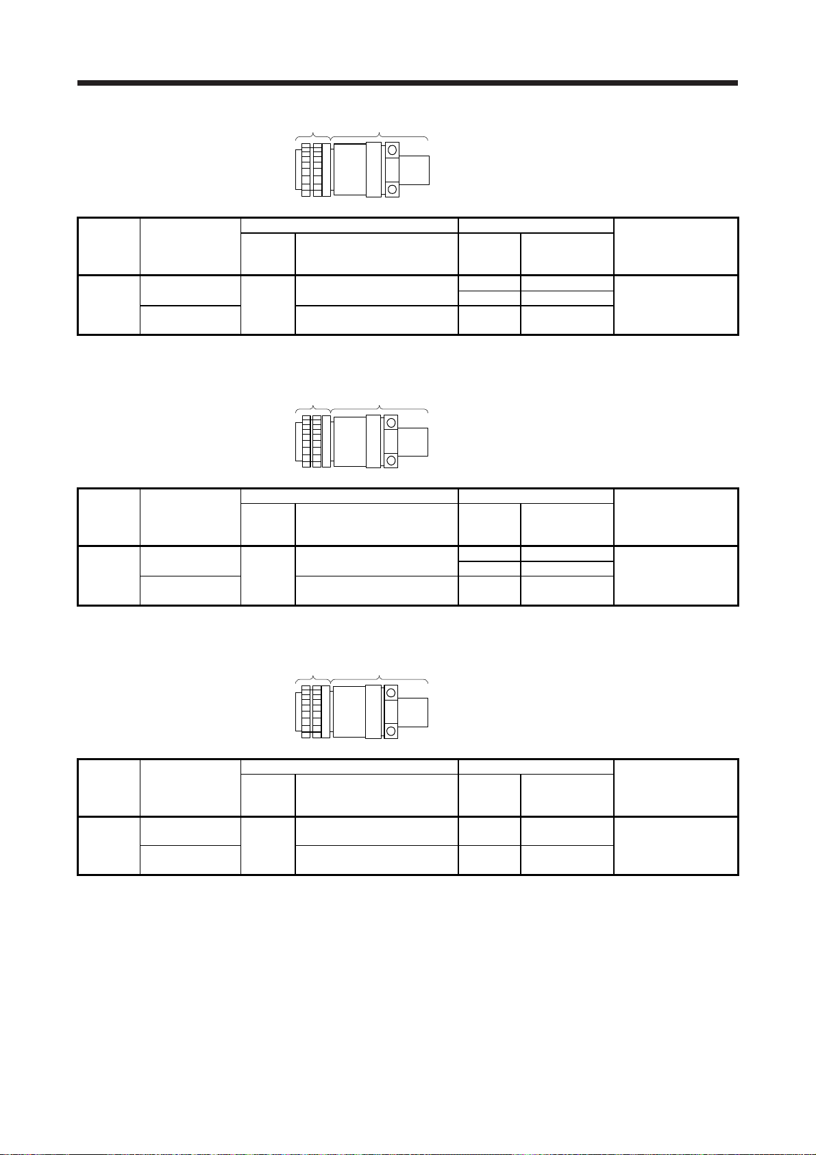
3. CONNECTORS USED FOR DIRECT DRIVE MOTOR WIRING
Connector
configuration
C
Feature
IP67
EN compliant
General environment
(Note 1)
Note 1. Not comply with EN.
2. The connector to be mated.
Connector
configuration
D
Feature
IP67
EN compliant
General environment
(Note 1)
Note 1. Not comply with EN.
2. The connector to be mated.
Plug
Cable clamp
Plug (DDK) Cable clamp (DDK)
Type Model
CE05-6A18-10SD-D-BSS
Straight
Applicable wire size: AWG 14 to 12
D/MS3106B18-10S
Applicable wire size: AWG 14 to 12
Cable clampPlug
Plug (DDK) Cable clamp (DDK)
Type Model
CE05-6A22-22SD-D-BSS
Straight
Applicable wire size: AWG 10 to 8
D/MS3106B22-22S
Applicable wire size: AWG 10 to 8
Cable clampPlug
Cable OD
[mm]
(reference)
8.5 to 11 CE3057-10A-2-D
10.5 to 14.1 CE3057-10A-1-D
14.3 or less
(bushing ID)
Cable OD
[mm]
(reference)
9.5 to 13 CE3057-12A-2-D
12.5 to 16 CE3057-12A-1-D
15.9 or less
(bushing ID)
Model
D/MS3057-10A
Model
D/MS3057-12A
Direct drive motor power
connector (Note 2)
CE05-2A18-10PD-D
Direct drive motor power
connector (Note 2)
CE05-2A22-22PD-D
Connector
configuration
E
Feature
IP67
EN compliant
General environment
(Note 1)
Note 1. Not comply with EN.
2. The connector to be mated.
Plug (DDK) Cable clamp (DDK)
Type Model
CE05-6A32-17SD-D-BSS
Straight
Applicable wire size: AWG 6 to 4
D/MS3106B32-17S
Applicable wire size: AWG 6 to 4
Cable OD
[mm]
(reference)
22 to 23.8 CE3057-20A-1-D
23.8 or less
(bushing ID)
Model
D/MS3057-20A
Direct drive motor power
connector (Note 2)
CE05-2A32-17PD-D
3 - 3
Page 23

3. CONNECTORS USED FOR DIRECT DRIVE MOTOR WIRING
Plug
Cord
clamp
Plug (Hirose Electric) Recommended cable (Bando Densen)
Connector
configuration
Feature
F IP67 Straight RM15WTPZ-12P(72) JR13WCCA-8(72)
Type Plug Cord clamp Model
Note 1. The connector to be mated.
2. Purchase from Toa Electric Industrial Co. Ltd., Nagoya Branch
20276
VSVPAWG#23×6P
KB-0492 (Note 2)
Cable OD
[mm]
(reference)
8.2 RM15WTRZB-12S(72)
Absolute position storage
unit connector
(encoder side) (Note 1)
3 - 4
Page 24
4. CONNECTOR DIMENSIONS
4. CONNECTOR DIMENSIONS
The following shows the dimensions of the connectors used for wiring the direct drive motor.
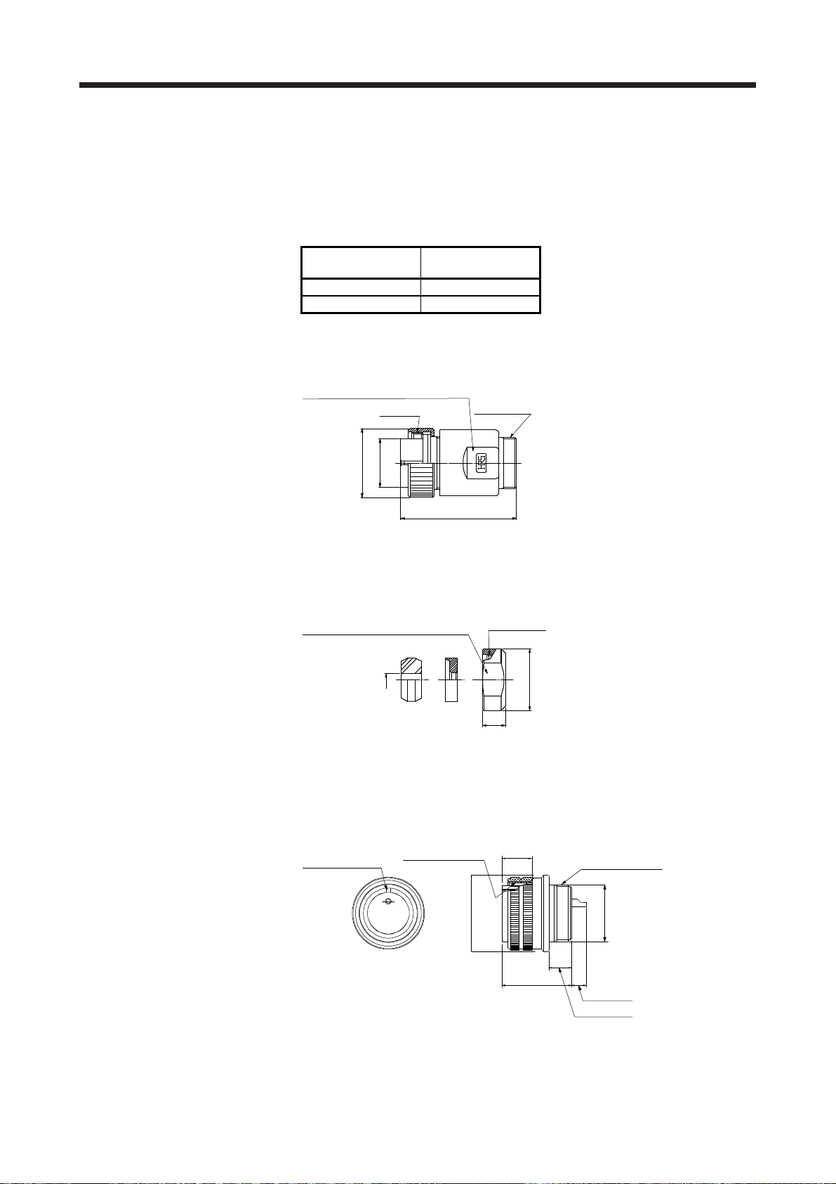
(1) Hirose Electric
(a) RM15WTPZK-12S/RM15WTPZ-12P(72)
Model
RM15WTPZK-12S A
RM15WTPZ-12P(72) F
Note. Refer to section 3.2 for the connector configuration.
Spanner hook gap dimension: 18
M19 × 1
φ15.2
φ21.5
Connector
configuration (Note)
[Unit: mm]
M16 × 0.75
(b) JR13WCCA-8(72)
Refer to the connector configurations A and F of section 3.2 for the connector configuration.
(2) DDK
(a) CE05-6A14S-2SD-D
Refer to the connector configuration B of section 3.2 for the connector configuration.
36.3
Spanner hook gap dimension: 17
8
Positioning key
7/8-20UNEF-2B
+ 0
- 0.38
[Unit: mm]
M16 × 0.75
φ20
7.5
(13.2)
[Unit: mm]
3/4-20UNEF-2A
φ28.57
φ17.0 ± 0.25
24.0 ± 1
5.6 ± 0.1
8.46 ± 0.5
4 - 1
Page 25

4. CONNECTOR DIMENSIONS
(b) CE05-6A18-10SD-D-BSS
CE05-6A22-22SD-D-BSS
CE05-6A32-17SD-D-BSS
Positioning key
[Unit: mm]
A
D
W
CE05-6A18-10SD-D-BSS 1 1/8-18UNEF-2B 34.13 32.1 57 1-20UNEF-2A C
CE05-6A22-22SD-D-BSS 1 3/8-18UNEF-2B 40.48 38.3 61 1 3/16-18UNEF-2A D
CE05-6A32-17SD-D-BSS 2-18UNS-2B 56.33 54.2 79 1 3/4-18UNS-2A E
Note. Refer to section 3.2 for the connector configuration.
(c) CE3057-10A-1-D
CE3057-10A-2-D
CE3057-12A-1-D
CE3057-12A-2-D
CE3057-20A-1-D
Model A B
A ± 0.7
V-thread
1.5
C
+0
-0.38
(D)
φB
C ± 0.8 D or less W
φC
Connector
configuration
(Note)
[Unit: mm]
φF
φB
Model
CE3057-10A1-D
CE3057-10A2-D
CE3057-12A1-D
CE3057-12A2-D
CE3057-20A1-D
Applicable
shell size
18 23.8 30.1 10.3 (41.3) 15.9
22 23.8 35 10.3 (41.3) 19
32 27.8 51.6 11.9 (43.0) 32.0 23.8 51.6 1 3/4-18UNS-2B CE3420-20-1 22.0 to 23.8 E
A B C (D) E F G V
Note. Refer to section 3.2 for the connector configuration.
G ± 0.7
(Bushing ID)
Enclosed
bushing
model
14.1
31.7 1-20UNEF-2B
11.0 CE3420-10-2 8.5 to 11
16.0
13.0 CE342012-2 9.5 to 13
1 3/16-18UNEF-
37.3
2B
CE3420-10-1 10.5 to 14.1
CE342012-1 12.5 to 16
φE
(Bushing OD)
Applicable
cable OD
(reference)
Connector
configuration
(Note)
C
D
4 - 2
Page 26

4. CONNECTOR DIMENSIONS
(d) D/MS3106B14S-2S
D/MS3106B18-10S
D/MS3106B22-22S
D/MS3106B32-17S
W or more
Y or less
Model A J L Q V W Y
D/MS3106B14S-2S 7/8-20UNEF 13.49 42.88 28.57 3/4-20UNEF 8.00 30 B
D/MS3106B18-10S 1 1/8-18UNEF 18.26 52.37 34.13 1-20UNEF 9.53 42 C
D/MS3106B22-22S 1 3/8-18UNEF 18.26 56.57 40.48 1 3/16-18UNEF 9.53 50 D
D/MS3106B32-17S 2-18UNS 18.26 61.92 56.33 1 3/4-18UNS 11.13 66 E
Note. Refer to section 3.2 for the connector configuration.
(e) D/MS3057-6A
D/MS3057-10A
D/MS3057-12A
D/MS3057-20A
Effective thread length C
L or less
V
1.6
J ± 0.12
A
0
φQ
A ± 0.12
V
-0.35
φE (Bushing ID)
G ± 0.7
[Unit: mm]
Connector
configuration
(Note)
[Unit: mm]
φD (Bushing OD)
φB ± 0.7
Connector
Model Shell size A B C D E G V Bushing
D/MS3057-6A 14S 22.2 24.6 10.3 11.2 7.9 27.0 3/4-20UNEF AN3420-6 B
D/MS3057-10A 18 23.8 30.1 10.3 15.9 14.3 31.7 1-20UNEF AN3420-10 C
D/MS3057-12A 22 23.8 35.0 10.3 19.0 15.9 37.3 1 3/16-18UNEF-2A AN3420-12 D
D/MS3057-20A 32 27.8 51.6 11.9 31.7 23.8 51.6 1 3/4-18UNS AN3420-20 E
configuration
Note. Refer to section 3.2 for the connector configuration.
4 - 3
(Note)
Page 27

4. CONNECTOR DIMENSIONS
(3) Daiwa Dengyo
[Unit: mm]
YSO14-5 to 8 4 to 8.3
YSO14-9 to
Note. Refer to the connector configuration B of section 3.2 for the connector configuration.
(4) Nippon Flex
Model
11
Applicable
cable OD
7 to 11.3
Hexagonal width
across flats D
O-ring
Hexagonal width
across flats φD2
Hexagonal width
across corners φD3
A
Hexagonal width
across corners φD1
A
L
Length before
tightening
L
Width
across
flats
D
Width
across
corners
D1
Width
across
flats
D2
Width
across
corners
D3
configuration
3/4-20UNEF-2B 44 23 25 26 28 B
(Note 1) L
(Note 1) L1
A15
(1)
(2)
E
G
Connector
(Note)
[Unit: mm]
Model Screw C
ACS-08RLMS14F
ACS-12RLMS14F
3/4-20UNEF-2B 4.0 to 8.0 7 15.0 20 22.0 6 22 24.2 6 46 41
3/4-20UNEF-2B
Applicable
cable OD
8.0 to
12.0
φd
E' × F' × G'
Screw C
Tightening nut Nipple body
A φd
7 15.0 24 26.4 6 36 28.6 6 46 41
E
Two-
face
width
F
Width
across
corners
G
Number
of
corners
E'
Two-
face
width
F'
Width
across
corners
G'
Number
of
corners
F
L L
configuration
1
Note 1. (1) indicates the reference dimension before assembling, and (2) indicates the reference dimension after assembling.
2. Refer to the connector configuration B of section 3.2 for the connector configuration.
Connector
(Note 2)
B
4 - 4
Page 28

5. CONNECTION OF SERVO AMPLIFIER AND DIRECT DRIVE MOTOR
5. CONNECTION OF SERVO AMPLIFIER AND DIRECT DRIVE MOTOR
Any person who is involved in wiring should be fully competent to do the work.
Ground the direct drive motor securely.
Do not attempt to wire the direct drive motor until it has been installed. Otherwise,
WARNING
CAUTION
it may cause an electric shock.
The cables should not be damaged, stressed, loaded, or pinched. Otherwise, it
may cause an electric shock.
To avoid an electric shock, insulate the connection areas of the power supply
terminals.
Wire the equipment correctly and securely. Otherwise, the direct drive motor may
operate unexpectedly, resulting in injury.
Connect cables to the correct terminals. Otherwise, a burst, damage, etc. may
occur.
Ensure that polarity (+/-) is correct. Otherwise, a burst, damage, etc. may occur.
Do not install a power capacitor, surge killer, or radio noise filter (FR-BIF option)
on the power line of the direct drive motor.
Do not modify the equipment.
Connect the servo amplifier power output (U/V/W) to the direct drive motor power
input (U/V/W) directly. Do not let a magnetic contactor, etc. intervene. Otherwise,
it may cause a malfunction.
Servo amplifier Servo amplifier
U
V
W
Direct drive
U
V
W
motor
M
U
V
W
Direct drive
U
V
W
motor
M
Before wiring, switch operation, etc., eliminate static electricity. Otherwise, it may
cause a malfunction.
POINT
We recommend using HIV wires to connect the servo amplifier to the direct drive
motor. Therefore, recommended wire sizes may different from those of the used
wires for the previous direct drive motors.
5 - 1
Page 29

5. CONNECTION OF SERVO AMPLIFIER AND DIRECT DRIVE MOTOR
5.1 Connection instructions
To avoid a malfunction, connect the power supply phases (U/V/W) of the servo
CAUTION
This section explains the connection of the direct drive motor power (U/V/W). Use of the optional connector
is recommended for connection between the servo amplifier and direct drive motor. Refer to chapter 6 for
details of the options.
For grounding, connect the grounding lead wire from the direct drive motor to the protective earth (PE)
terminal of the servo amplifier, and then connect the wire from the servo amplifier to the ground via the
protective earth of the cabinet. Do not connect the wire directly to the protective earth of the cabinet.
amplifier and the direct drive motor correctly.
Do not connect AC power supply directly to the direct drive motor. Otherwise, it
may cause a malfunction.
POINT
Refer to chapter 6 for the encoder cable.
Cabinet
Servo
amplifier
PE terminal
Note. The number of PE terminals of the servo amplifier differs depending on the amplifier
type.
(Note)
5.2 Direct drive motor power cable wiring diagram
Fabricate a cable as shown below.
Refer to section 5.3 for the wires used for the cable.
U
V
W
(Note)
Direct drive motor
30 m or less
Direct drive motorServo amplifier
U
V
M
W
Note. This grounding is for the MR-J4 1-axis servo amplifier. For the MR-J4 multi-axis
servo amplifier, connect the grounding lead wire to the connector for CNP3_.
5 - 2
Page 30

5. CONNECTION OF SERVO AMPLIFIER AND DIRECT DRIVE MOTOR
5.3 Selection example of wires
POINT
Wires indicated in this section are separated wires.
Selection condition of wire size is as follows.
Construction condition: Single wire set in midair.
Wire length: 30 m or less
The following shows examples for using the 600 V Grade heat-resistant polyvinyl chloride insulated wire
(HIV wire).
(1) TM-RFM series
(2) TM-RG2M series/TM-RU2M series
2
Direct drive motor
TM-RFM002C20
TM-RFM004C20
TM-RFM006C20
TM-RFM006E20 1.25 (AWG 16)
TM-RFM012E20
TM-RFM018E20
TM-RFM012G20
TM-RFM048G20
TM-RFM072G20
TM-RFM040J10 1.25 (AWG 16)
TM-RFM120J10 3.5 (AWG 12)
TM-RFM240J10 5.5 (AWG 10) (Note)
Note. Refer to each servo amplifier instruction manual for crimp terminals used for
connection with the servo amplifier.
Direct drive motor
TM-RG2M002C30
TM-RU2M002C30
TM-RG2M004E30
TM-RU2M004E30
TM-RG2M009G30
TM-RU2M009G30
Wire [mm
U/V/W/
3.5 (AWG 12)
Wire [mm
U/V/W/
0.75 (AWG 18)
]
2
]
5 - 3
Page 31

5. CONNECTION OF SERVO AMPLIFIER AND DIRECT DRIVE MOTOR
5.4 Servo amplifier terminal section
POINT
For the sizes of wires used for wiring, refer to section 5.3.
When wiring, remove the power connectors from the servo amplifier.
Insert only one wire or ferrule to each wire insertion hole.
To wire to the servo amplifier, use connectors packed with the servo amplifier or optional connectors.
The following table shows the connectors to be connected to the servo amplifiers. The numbers in the rated
output field of the table indicate the symbol filling the underline "_" in the servo amplifier model. For details of
the connectors, refer to (1) in this section. For wiring, refer to (2) in this section.
Servo amplifier
MR-J4-_A
MR-J4-_A-RJ
MR-J4-_B
MR-J4-_B-RJ
MR-J4-_GF
MR-J4-_GF-RJ
10 20 40 60 70 100 200 350 500 700 11K 15K 22K
Note. For details on the terminal block, refer to each servo amplifier instruction manual.
Servo amplifier
MR-J4-_A1
MR-J4-_A1-RJ
MR-J4-_B1
MR-J4-_B1-RJ
Rated output
10 20 40
Connector A
Servo amplifier
MR-J4W2-_B Connector C
MR-J4W3-_B Connector C
22 (222) 44 (444) 77 1010
Note. The numbers in parentheses are for the MR-J4 3-axis servo amplifier.
Rated output
Connector A Connector B None (Terminal box) (Note)
Rated output (Note)
5 - 4
Page 32

5. CONNECTION OF SERVO AMPLIFIER AND DIRECT DRIVE MOTOR
r
(1) Connector details
(a) Connector A
Servo amplifie
CNP3
Table 5.1 Connector and applicable wire
Connector Receptacle assembly
CNP3 03JFAT-SAXGDK-H7.5 AWG 18 to 14 3.9 mm or shorter 9
(b) Connector B
MR-J4-200_(-RJ)
Servo amplifier
Applicable wire
Wire size Insulator OD
Stripped
length [mm]
MR-J4-350_(-RJ)
Servo amplifier
Open tool
J-FAT-OT (N)
or
J-FAT-OT
Manufac-
turer
JST
CNP3
Connector Receptacle assembly
CNP3 03JFAT-SAXGFK-XL AWG 16 to 10 4.7 mm or shorter 11.5 J-FAT-OT-EXL JST
CNP3
Table 5.2 Connector and applicable wire
Applicable wire
Wire size Insulator OD
Stripped
length [mm]
Open tool
Manufac-
turer
5 - 5
Page 33

5. CONNECTION OF SERVO AMPLIFIER AND DIRECT DRIVE MOTOR
(c) MR-J4W_ - _B
Servo amplifier
CNP3A
CNP3B
CNP3C
(Note)
Note. For the 3-axis servo amplifier.
Table 5.3 Connector and applicable wire
Connector Receptacle assembly
CNP3A
CNP3B
CNP3C
04JFAT-SAGG-G-KK AWG 18 to 14 9 J-FAT-OT-EXL JST
(2) Cable connection procedure
(a) Fabrication on cable insulator
Refer to tables 5.1 to 5.3 for stripped length of cable insulator. The appropriate stripped length of
cables depends on their type, etc. Set the length considering their fabrication status.
Applicable wire
size
Insulator
Stripped length
[mm]
Core
Open tool Manufacturer
Stripped length
Twist strands lightly and straighten them as follows.
Loose and bent cores Twist and straighten
the cores.
5 - 6
Page 34

5. CONNECTION OF SERVO AMPLIFIER AND DIRECT DRIVE MOTOR
(b) Inserting wire
Insert the open tool as follows and push down it to open the spring.
While the open tool is pushed down, insert the stripped wire into the wire insertion hole. Check the
wire insertion depth, and make sure that the cable insulator will not be caught by the spring and that
the conductive part of the stripped wire will not be exposed.
Release the open tool to fix the wire. Pull the wire lightly to confirm that the wire is surely connected.
In addition, make sure that no conductor wire sticks out of the connector.
The following shows a connection example of the CNP3 connector for 2 kW and 3.5 kW of MR-J4 1axis servo amplifier.
1) Push down the open tool.
3) Release the open tool to fix the wire.
2) Insert the wire.
5 - 7
Page 35

5. CONNECTION OF SERVO AMPLIFIER AND DIRECT DRIVE MOTOR
MEMO
5 - 8
Page 36

6. WIRING OPTION
6. WIRING OPTION
Before connecting any option or peripheral equipment, turn off the power and wait
for 15 minutes or more until the charge lamp turns off. Then, confirm that the
WARNING
CAUTION
6.1 Connector set
voltage between P+ and N- is safe with a voltage tester and others. Otherwise, an
electric shock may occur. In addition, when confirming whether the charge lamp is
off or not, always confirm it from the front of the servo amplifier.
Use specified auxiliary equipment and options. Otherwise, it may cause a
malfunction or fire.
POINT
We recommend using HIV wires to wire the servo amplifiers, direct drive motors,
options, and peripheral equipment. Therefore, recommended wire sizes may
different from those of the used wires for the previous direct drive motors.
POINT
The IP rating indicated is the connector's protection against ingress of dust and
water when the connector is connected to a servo amplifier, direct drive motor,
or absolute position storage unit. If the IP rating of the connector, servo
amplifier, direct drive motor, and absolute position storage unit vary, the overall
IP rating depends on the lowest IP rating of all components.
For the connectors used with this direct drive motor, purchase the options indicated in this section. When
fabricating an encoder cable, refer to app. 4.
6 - 1
Page 37

6. WIRING OPTION
A
6.1.1 Combinations of connector set
MR-J4 1-axis
servo amplifier
1)
2) 3)
CNP3
(Note 1)
MR-J4 multi-axis
CNP3A
CNP3B
CNP3C
(Note 4)
Note 1. Connectors for 3.5 kW or less. For 5 kW or more, it is a terminal block.
2.
3. This connection is for the MR-J4 3-axis servo amplifier.
4. Refer to Appendix 3 for the crimp connector for CNP3_.
(Note 3)
lways make connection for use in an absolute position detection system. (Refer to section 6.3.)
CN2
or
servo amplifier
CN2A
CN2B
CN2C
(Note 3)
For incremental system
For absolute position detection system
Absolute position storage
unit MR-BTAS01 (Note 2)
4)
5)
5) 6)
Encoder
connector
Direct drive motor
Power supply
TM-RFM
TM-RG2M
TM-RU2M
connector
6 - 2
Page 38

6. WIRING OPTION
6.1.2 Connector list
No. Product Model Description Remark
1) Power connector
set
2) Power connector
set
3) Power connector
set
4) Power connector
set
5) Encoder
connector set
6) Encoder
connector set
MR-PWCNF Plug: CE05-6A14S-2SD-D (DDK)
Cable clamp: YSO14-9 to 11 (Daiwa Dengyo)
Applicable cable
Applicable wire size: 0.3 mm
2
mm
(AWG 16)
Cable outer diameter: 8.3 mm to 11.3 mm
MR-PWCNS4 Plug: CE05-6A18-10SD-D-BSS
Cable clamp: CE3057-10A-1-D
(DDK)
Applicable cable
Applicable wire size: 2 mm
(AWG 12)
Cable outer diameter: 10.5 mm to 14.1 mm
MR-PWCNS5 Plug: CE05-6A22-22SD-D-BSS
Cable clamp: CE3057-12A-1-D
(DDK)
Applicable cable
Applicable wire size: 5.5 mm
(AWG 8)
Cable outer diameter: 12.5 mm to 16 mm
MR-PWCNS3 Plug: CE05-6A32-17SD-D-BSS
Cable clamp: CE3057-20A-1-D
(DDK)
Applicable cable
Applicable wire size: 14 mm
(AWG 4)
Cable outer diameter: 22 mm to 23.8 mm
MR-J3DDCNS
For connection between servo amplifier and direct drive motor.
For connection between servo amplifier and absolute position storage unit.
Refer to section 6.2 for details.
MR-J3DDSPS
For connection between absolute position storage unit and direct drive motor.
Refer to section 6.2 for details.
2
(AWG 22) to 1.25
2
(AWG 14) to 3.5 mm2
2
(AWG 10) to 8 mm2
2
(AWG 6) to 22 mm2
For TM-RFM_C20
For TM-RFM_E20
For TM-RG2M_C30
For TM-RG2M_E30
For TM-RG2M_G30
For TM-RU2M_C30
For TM-RU2M_E30
For TM-RU2M_G30
For TM-RFM_G20
For TM-RFM040J10
For TM-RFM120J10
For TM-RFM240J10
IP67
EN
compliant
IP67
EN
compliant
IP67
EN
compliant
IP67
EN
compliant
IP67
IP67
6 - 3
Page 39

6. WIRING OPTION
6.2 Encoder connector set
POINT
The encoder cable should be fabricated by the customer. Fabricate the encoder
cable according to section 6.2.1 to section 6.2.3 and the wiring diagram in
section 6.2.4.
Fabricate the encoder cable to be 50 m or shorter between the servo amplifier
and the direct drive motor.
To configure the absolute position detection system, always connect the battery
and absolute position storage unit to the servo amplifier. For details of the
battery, refer to each servo amplifier instruction manual. Refer to section 6.3 for
details of the absolute position storage unit.
For absolute position detection system, refer to each servo amplifier instruction
manual.
For CN2, CN2A, CN2B, and CN2C side connectors, securely connect the
external conductor of the shielded cable to the ground plate and fix it to the
connector shell.
Cable
Ground plate
Screw
6.2.1 MR-J3DDCNS
This connector set is used to fabricate an encoder cable for the incremental system or the absolute position
detection system (between the servo amplifier and the absolute position storage unit).
Parts Description
Connector set MR-J3DDCNS
Servo amplifier side connector
Receptacle: 36210-0100PL
Shell kit: 36310-3200-008
(3M)
or
Connector set: 54599-1019
(Molex)
Applicable wire size: 0.25 mm2 (AWG 23) to 0.5 mm2 (AWG 20)
Encoder-side or absolute position storage
unit-side connector (connected from the
servo amplifier)
Plug: RM15WTPZK-12S
Cord clamp: JR13WCCA-8(72)
(Hirose Electric)
6 - 4
Page 40

6. WIRING OPTION
6.2.2 MR-J3DDSPS
This connector set is used to fabricate an encoder cable for the absolute position detection system (between
the absolute position storage unit and the direct drive motor).
6.2.3 Combinations for the encoder cable
(1) For incremental system
Parts Description
Connector set MR-J3DDSPS
Absolute position storage unit-side
connector
Plug: RM15WTPZ-12P(72)
Cord clamp: JR13WCCA-8(72)
(Hirose Electric)
Applicable wire size: 0.25 mm2 (AWG 23) to 0.5 mm2 (AWG 20)
MR-J4 1-axis
servo amplifier
CN2
50 m or shorter
Encoder-side connector
Plug: RM15WTPZK-12S
Cord clamp: JR13WCCA-8(72)
(Hirose Electric)
or
MR-J4 multi-axis
servo amplifier
CN2A
CN2B
CN2C
Note 1. Refer to section 6.2.4 (1) for details.
2. This connection is for the MR-J4 3-axis servo amplifier.
(2) For absolute position detection system
MR-J4 1-axis
servo amplifier
CN2
(Note 1) Encoder cable B
or
MR-J4 multi-axis
servo amplifier
3)
(Note 1) Encoder cable A
1)
(Note 2)
20 m or shorter (Note 4)
4)
2)
(Note 2) Encoder cable C
5) 6)
Direct drive motor
TM-RFM
TM-RG2M
TM-RU2M
Direct drive motor
TM-RFM
TM-RG2M
TM-RU2M
CN2A
CN2B
CN2C
Note 1. Refer to section 6.2.4 (2) for details.
2. Refer to section 6.2.4 (3) for details.
3. This connection is for the MR-J4 3-axis servo amplifier.
4. For cable of 20 m or more, contact your local sales office.
(Note 3)
Absolute position
storage unit
MR-BTAS01
6 - 5
Page 41

6. WIRING OPTION
6.2.4 Fabrication of the encoder cable
(1) Encoder cable A
(a) Connector details
Receptacle: 36210-0100PL
Shell kit: 36310-3200-008
(3M)
2
LG 8
1
P5
View seen from the wiring side.
(Note 1)
1) CN2, CN2A, CN2B, and CN2C side connector 2) Encoder-side connector
4
MRR
3
6
THM2
5
THM1
10
9
7
MR
Connector set: 54599-1019
(Molex)
4
2
or
LG
1P53
View seen from the wiring side.
(Note 1)
MRR
MR
THM2
5
THM1
86 10
7 9
Straight plug: RM15WTPZK-12S
Cord clamp: JR13WCCA-8(72)
(Hirose Electric)
Recommended cable:
20276 VSVPAWG#23×6P KB-0492
(Note 3)
(Bando Densen)
1
9 8
MRR
P5
12
10
2
LG
3
11
THM2
FG
MR
6
THM1
54
7
Note 1. Do not connect anything to the pins shown as . Especially, the pin 10 is for manufacturer adjustment. If it is
connected with any other pin, the servo amplifier cannot operate normally. Referring to POINT of section 6.2,
securely connect the external conductor of the shielded cable to the ground plate and fix it to the connector shell.
2. Do not connect anything to the pins shown as
3. Purchase from Toa Electric Industrial Co. Ltd., Nagoya Branch
(b) Cable internal wiring diagram
1) CN2, CN2A, CN2B, and
CN2C side connector
P5
LG
1
2
MR
MRR34
5
Plate
.
2) Encoder-side
connector
9
10
7
8
6
116 THM2THM2
5
View seen from the wiring side. (Note 2)
P5
LG
MR
MRR
THM1THM1
FGSD
Refer to the following table for the required wires to fabricate the encoder cable.
Core size [mm2]
0.25 63.6 or less 8.2
Conductor resistance of
one core [Ω/km]
Cable OD [mm]
6 - 6
Page 42

6. WIRING OPTION
(2) Encoder cable B
(a) Connector details
3) CN2, CN2A, CN2B, and CN2C side connector
Receptacle: 36210-0100PL
Shell kit: 36310-3200-008
(3M)
2
LG 8
1
P5
View seen from the wiring side.
(Note 1)
4
MRR
3
MR
6
THM2
5
4) Absolute position storage unit-side
connector
Connector set: 54599-1019
(Molex)
Straight plug: RM15WTPZK-12S
Cord clamp: JR13WCCA-8(72)
(Hirose Electric)
Recommended cable:
10
9
BATTHM1
7
or
4
2
MRR
LG
1P53
MR
View seen from the wiring side.
(Note 1)
THM2
5
THM1
86 10
7 9
BAT
20276 VSVPAWG#23×6P KB-0492
(Note 3)
(Bando Densen)
1
9 8
MRR
P5
12
10
2
BAT
LG
3
11
THM2
FG
MR
6
THM1
54
7
Note 1. Do not connect anything to the pins shown as . Especially, the pin 10 is provided for manufacturer
adjustment. If it is connected with any other pin, the servo amplifier cannot operate normally. Referring to POINT
of section 6.2, securely connect the external conductor of the shielded cable to the ground plate and fix it to the
connector shell.
2. Do not connect anything to the pins shown as
3. Purchase from Toa Electric Industrial Co. Ltd., Nagoya Branch
(b) Cable internal wiring diagram
View seen from the wiring side. (Note 2)
.
When the distance between the servo amplifier and the
direct drive motor is within 20 m (Note)
3) CN2, CN2A, CN2B, and
CN2C side connector
P5
LG
1
2
MR
MRR34
5
BAT
9
PlateSD
4) Absolute position storage
unit-side connector
9
P5
LG
10
MR
7
MRR
8
6
THM1THM1
116
THM2THM2
2 BAT
5FG
Note. For the cable of 20 m or longer, contact your local sales office.
Refer to the following table for the required wires to fabricate the encoder cable.
Core size [mm2]
0.25 63.6 or less 8.2
Conductor resistance of
one core [Ω/km]
Cable OD [mm]
6 - 7
Page 43

6. WIRING OPTION
(3) Encoder cable C
(a) Connector details
5) Absolute position storage unit-side
connector
Straight plug: RM15WTPZ-12P(72)
Cord clamp: JR13WCCA-8(72)
(Hirose Electric)
Recommended cable:
20276 VSVPAWG#23×6P KB-0492 (Note 2)
(Bando Densen)
1
98
MRR
P5
VB
10
7612
MR
THM1
11
THM2
5LG4
FG
2
BAT
3
6) Encoder-side connector
Straight plug: RM15WTPZK-12S
Cord clamp: JR13WCCA-8(72)
(Hirose Electric)
Recommended cable:
20276 VSVPAWG#23×6P KB-0492 (Note 2)
(Bando Densen)
1
9 8
MRR
P5
VB
10
BAT
2
LG
3
11
THM2
4
FG
7
12
MR
6
THM1
5
(b) Cable internal wiring diagram
View seen from the wiring side. (Note 1)
View seen from the wiring side. (Note 1)
Note 1. Do not connect anything to the pins shown as .
2. Purchase from Toa Electric Industrial Co. Ltd., Nagoya Branch
When the distance between the servo amplifier and
the direct drive motor is within 20 m (Note)
5) Absolute position storage
unit-side connector
P5
LG
9
10
6) Encoder-side
connector
P5
9
10
LG
MR
MRR78
BAT
FG 5 FG5
6
2
MR
7
MRR
8
THM1THM1
6
1111 THM2THM2
11VBVB
BAT
2
Note. For the cable of 20 m or longer, contact your local sales office.
Refer to the following table for the wires required to fabricate the encoder cable.
Core size [mm2]
0.25 63.6 or less 8.2
Conductor resistance of
one core [Ω/km]
Cable OD [mm]
6 - 8
Page 44

6. WIRING OPTION
6.3 Absolute position storage unit MR-BTAS01
POINT
Replacing the MR-BTAS01 absolute position storage unit will erase the absolute
position. Start up the direct drive motor again and perform home positioning
according to each servo amplifier instruction manual.
For absolute position detection system, refer to each servo amplifier instruction
manual.
[AL. 25 Absolute position erased] will occur if the encoder cable is disconnected.
(1) Connection method with the encoder cable
Refer to section 6.2.3 (2).
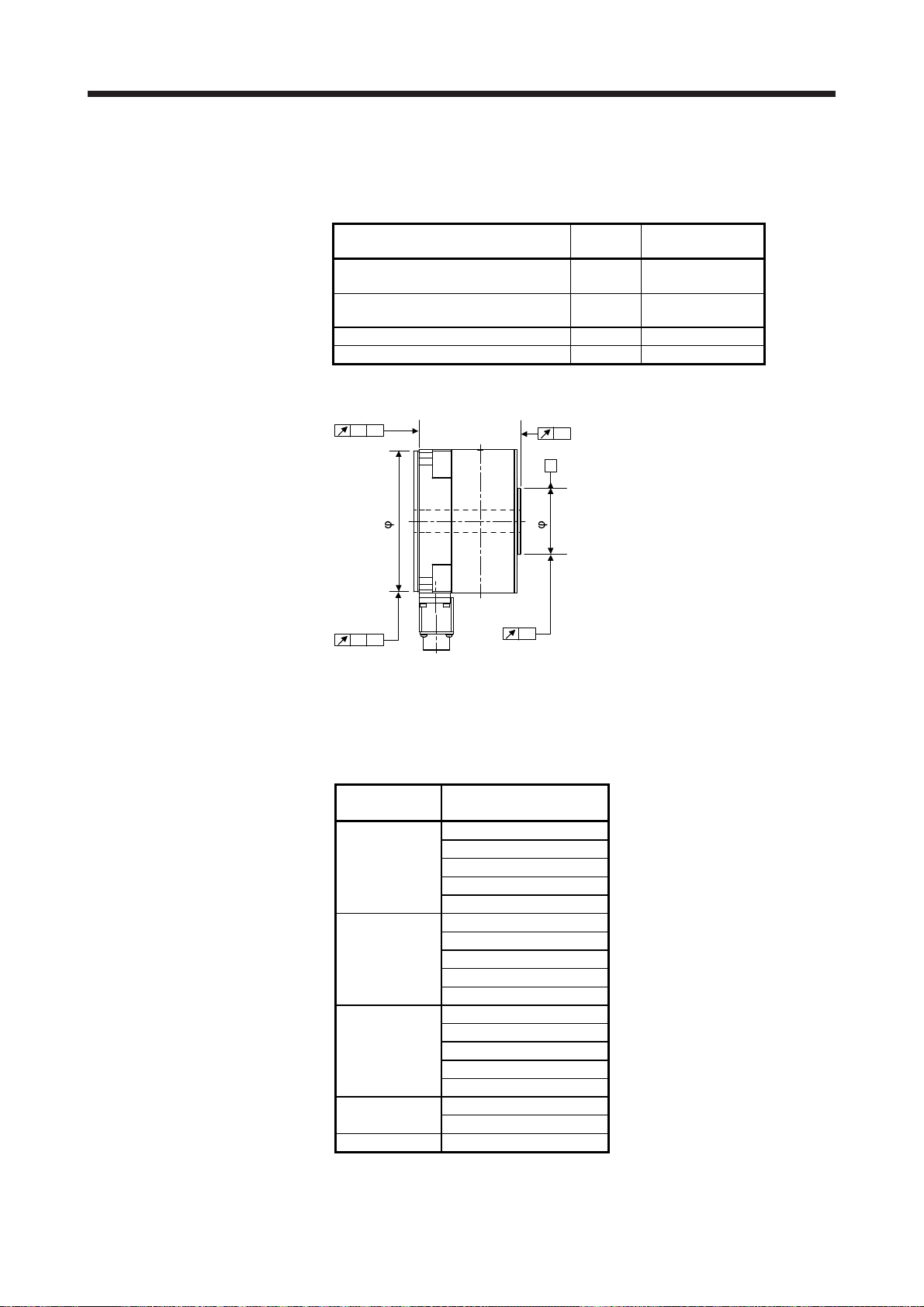
(2) Dimensions
RM15WTRZB-12P (72)
(servo amplifier side)
19 19
RM15WTRZB-12S (72)
(encoder side)
[Unit: mm]
16
2-φ6 mounting hole
63
30
5
45.2
20
22
69.855
79.8
81
Note. When mounting the unit outside the cabinet, fix the mounting surface A with four screws. When mounting the unit
inside the cabinet, you can also fix the mounting surface B with two screws.
3
R
6
5
45.2
20
Mounting surface B (Note)
15
6
R
3
(3) Environment
The following table indicates the environment for the absolute position storage unit.
Item Environment
Ambient
temperature
Ambient
humidity
Ambience
Altitude Max. 2000 m above sea level
Vibration resistance
Operation 0 ˚C to 55 ˚C (non-freezing)
Storage -20 ˚C to 65 ˚C (non-freezing)
Operation 10 %RH to 90 %RH (non-condensing)
Storage 10 %RH to 90 %RH (non-condensing)
Indoors (no direct sunlight),
free from corrosive gas, flammable gas, oil mist, dust, oil and water.
When the mounting surface A is fixed: 49 m/s
When the mounting surface B is fixed: 5.9 m/s
Mounting screw size: M5
Mounting surface A (Note)
Mass: 0.26 kg
2
(directions of X, Y, and Z axes)
2
(directions of X, Y, and Z axes)
6 - 9
Page 45

6. WIRING OPTION
MEMO
6 - 10
Page 46

7. TM-RFM SERIES
7. TM-RFM SERIES
This chapter provides information on the direct drive motor specifications and characteristics. When using
the TM-RFM series direct drive motor, always read the Safety Instructions in the beginning of this manual in
addition to this chapter.
7.1 Model code definition
The following describes what each block of a model name indicates. Note that not all the combinations of the
symbols exist.
Rated torque
Symbol
002 2
004 4
006 6
012 12
018 18
040 40
048 48
072 72
120 120
240 240
Series
C20TM-RFM 020
Rated speed
Symbol
Motor OD (Frame OD)
Symbol
Rated speed [r/min]
10 100
20 200Rated torque [N•m]
Dimensions [mm]
C φ130
E
G φ230
J φ330
φ180
Outer appearance
Z-phase mark
7 - 1
Page 47

7. TM-RFM SERIES
7.2 Combinations of servo amplifier and direct drive motor
Direct drive motor
TM-RFM002C20
TM-RFM004C20
TM-RFM006C20
TM-RFM006E20
TM-RFM012E20
TM-RFM018E20
TM-RFM012G20
TM-RFM048G20
TM-RFM072G20
TM-RFM040J10
TM-RFM120J10
TM-RFM240J10
200 V class 100 V class
MR-J4-20A
MR-J4-20A-RJ
MR-J4-20B
MR-J4-20B-RJ
MR-J4-20GF
MR-J4-20GF-RJ
MR-J4-40A
MR-J4-40A-RJ
MR-J4-40B
MR-J4-40B-RJ
MR-J4-40GF
MR-J4-40GF-RJ
MR-J4-60A
MR-J4-60A-RJ
MR-J4-60B
MR-J4-60B-RJ
MR-J4-60GF
MR-J4-60GF-RJ
MR-J4-70A
MR-J4-70A-RJ
MR-J4-70B
MR-J4-70B-RJ
MR-J4-70GF
MR-J4-70GF-RJ
MR-J4-100A
MR-J4-100A-RJ
MR-J4-100B
MR-J4-100B-RJ
MR-J4-100GF
MR-J4-100GF-RJ
MR-J4-70A
MR-J4-70A-RJ
MR-J4-70B
MR-J4-70B-RJ
MR-J4-70GF
MR-J4-70GF-RJ
MR-J4-350A
MR-J4-350A-RJ
MR-J4-350B
MR-J4-350B-RJ
MR-J4-350GF
MR-J4-350GF-RJ
MR-J4-70A
MR-J4-70A-RJ
MR-J4-70B
MR-J4-70B-RJ
MR-J4-70GF
MR-J4-70GF-RJ
MR-J4-350A
MR-J4-350A-RJ
MR-J4-350B
MR-J4-350B-RJ
MR-J4-350GF
MR-J4-350GF-RJ
MR-J4-500A
MR-J4-500A-RJ
MR-J4-500B
MR-J4-500B-RJ
MR-J4-500GF
MR-J4-500GF-RJ
1-axis
MR-J4-20A1
MR-J4-20A1-RJ
MR-J4-20B1
MR-J4-20B1-RJ
MR-J4-40A1
MR-J4-40A1-RJ
MR-J4-40B1
MR-J4-40B1-RJ
Servo amplifier
MR-J4W2-22B
MR-J4W2-44B
MR-J4W2-44B
MR-J4W2-77B
MR-J4W2-1010B
MR-J4W2-77B
MR-J4W2-1010B
MR-J4W2-77B
MR-J4W2-1010B
MR-J4W2-1010B
MR-J4W2-77B
MR-J4W2-1010B
MR-J4W2-77B
MR-J4W2-1010B
2-axis 3-axis
MR-J4W3-222B
MR-J4W3-444B
MR-J4W3-444B
7 - 2
Page 48

7. TM-RFM SERIES
7.3 Specification list
Direct drive motor
Item
Motor OD (frame OD) [mm] φ130 φ180
Power supply capacity
Continuous running
duty (Note 1)
Maximum torque [N•m] 6 12 18 18 36 54
Rated speed (Note 1) [r/min] 200
Maximum speed [r/min] 500
Instantaneous permissible speed [r/min] 575
Power rate at continuous rated torque [kW/s] 3.7 9.6 16.1 4.9 12.9 21.8
Rated current [A] 1.3 2.2 3.2 3.0 3.8 6.0
Maximum current [A] 3.9 6.6 9.6 9.0 12 18
Moment of inertia J [× 10-4 kg•m2] 10.9 16.6 22.4 74.0 111 149
Recommended load to motor inertia ratio
(Note 2)
Absolute accuracy (Note 9) [s] ±15 ±12.5
Speed/position detector (Note 3)
Thermistor Built-in
Insulation class 155 (F)
Structure Totally enclosed, natural cooling (IP rating: IP42 (Note 4))
Environment
(Note 5)
Vibration rank (Note 7) V10
Rotor permissible
load (Note 8)
Mass [kg] 5.2 6.8 8.4 11 15 18
Rated output [W] 42 84 126 126 251 377
Rated torque [N•m] 2 4 6 6 12 18
Ambient
temperature
Ambient
humidity
Ambience
Altitude Max. 2000 m above sea level (Note 10)
Vibration resistance
(Note 6)
Moment load [N•m] 22.5 70
Axial load [N] 1100 3300
Operation 0 ˚C to 40 ˚C (non-freezing)
Storage -15 ˚C to 70 ˚C (non-freezing)
Operation 10 %RH to 80 %RH (non-condensing)
Storage 10 %RH to 90 %RH (non-condensing)
TM-RFM series
002C20 004C20 006C20 006E20 012E20 018E20
Refer to "USING A DIRECT DRIVE MOTOR" of each servo amplifier instruction
manual.
50 times or less
20-bit encoder common to absolute position and incremental detection systems
(resolution per direct drive motor revolution: 1048576 pulses/rev)
Indoors (no direct sunlight),
free from corrosive gas, flammable gas, oil mist, dust, oil and water.
X: 49 m/s
2
Y: 49 m/s2
7 - 3
Page 49

7. TM-RFM SERIES
Direct drive motor
Item
Motor OD (frame OD) [mm] φ230 φ330
Power supply capacity
Continuous running
duty (Note 1)
Maximum torque [N•m] 36 144 216 120 360 720
Rated speed (Note 1) [r/min] 200 100
Maximum speed [r/min] 500 200
Instantaneous permissible speed [r/min] 575 230
Power rate at continuous rated torque [kW/s] 6.0 37.5 59.3 9.4 40.9 91.4
Rated current [A] 3.6 11 16 4.3 11 19
Maximum current [A] 11 33 48 13 33 57
Moment of inertia J [× 10-4 kg•m2] 238 615 875 1694 3519 6303
Recommended load to motor inertia ratio
(Note 2)
Absolute accuracy (Note 9) [s] ±12.5 ±10
Speed/position detector (Note 3)
Thermistor Built-in
Insulation class 155 (F)
Structure Totally enclosed, natural cooling (IP rating: IP42 (Note 4))
Environment
(Note 5)
Vibration rank (Note 7) V10
Rotor permissible
load (Note 8)
Mass [kg] 17 36 52 53 91 146
Rated output [W] 251 1005 1508 419 1257 2513
Rated torque [N•m] 12 48 72 40 120 240
Ambient
temperature
Ambient
humidity
Ambience
Altitude Max. 2000 m above sea level (Note 10)
Vibration resistance
(Note 6)
Moment load [N•m] 93 350
Axial load [N] 5500 16000
Operation 0 ˚C to 40 ˚C (non-freezing)
Storage -15 ˚C to 70 ˚C (non-freezing)
Operation 10 %RH to 80 %RH (non-condensing)
Storage 10 %RH to 90 %RH (non-condensing)
TM-RFM series
012G20 048G20 072G20 040J10 120J10 240J10
Refer to "USING A DIRECT DRIVE MOTOR" of each servo amplifier instruction
manual.
50 times or less
20-bit encoder common to absolute position and incremental detection systems
(resolution per direct drive motor revolution: 1048576 pulses/rev)
Indoors (no direct sunlight),
free from corrosive gas, flammable gas, oil mist, dust, oil and water.
X: 49 m/s
2
Y: 49 m/s2 X: 24.5 m/s2 Y: 24.5 m/s2
7 - 4
Page 50

7. TM-RFM SERIES
A
Note 1. When the power supply voltage drops, the output and the rated speed cannot be guaranteed.
2. If the load inertia moment ratio exceeds the indicated value, contact your local sales office.
3. To configure the absolute position detection system, always connect the battery and absolute position storage unit to the servo
amplifier. For details of the battery, refer to each servo amplifier instruction manual. Refer to section 6.3 for details of the
absolute position storage unit.
4. Shaft-through portion of the rotor and the connector area are excluded. IP classifies the degrees of protection provided against
the intrusion of solid objects and water in electrical enclosures.
5. In the environment where the direct drive motor is exposed to oil mist, oil, and water, a standard specification direct drive
motor cannot be used. Provide measures to prevent dust and/or water on the machine side.
6. The following figure shows the vibration direction. The indicated values are the maximum values. When the direct drive motor
stops, fretting is likely to occur at the bearing. Therefore, suppress the vibration to about the half the permissible value.
Y
X
7. V10 indicates that the amplitude of a direct drive motor alone is 10 μm or less. The following figure shows the direct drive
motor installation position for measurement and the measuring position.
Measuring position
8. Axial and moment loads, which are applied to the direct drive motor's rotor (output shaft) during operation, can be calculated
as below. The axial and moment loads must be maintained to be equal to or below the permissible value.
F (Outer force)
xial load
= F + load mass
F (Outer force)
L
Axial load
= F + load mass
Moment load
= F × L
F (Outer force)
Bearing
Axial load
= Load mass
Moment load
= F × (L + A)
Direct drive motor
L
TM-RFM002C20
A
TM-RFM004C20
TM-RFM006C20
TM-RFM006E20
TM-RFM012E20
TM-RFM018E20
TM-RFM012G20
TM-RFM048G20
TM-RFM072G20
TM-RFM040J10
TM-RFM120J10
TM-RFM240J10
Motor OD
[mm]
φ130 19.1
φ180 20.2
φ230 24.4
φ330 32.5
Dimension
A
[mm]
9. Absolute accuracy changes depending on the mounting condition of the load and the surrounding environment.
10. Follow the restrictions in section 2.10 when using this product at altitude exceeding 1000 m and up to 2000 m above sea level.
7 - 5
Page 51

7. TM-RFM SERIES
7.4 Torque characteristics
POINT
For the machine where the unbalanced torque occurs, such as a vertical axis
system (lift), use the absolute position detection system. (Refer to section 2.1
(4).) The unbalanced torque of the machine should be kept at 70% or lower of
the motor's rated torque.
Bold lines indicate the torque characteristics with the 3-phase 200 V AC power supply input or 1-phase 230
V AC power supply input to the servo amplifier. For the 1-phase 200 V AC power supply input, part of the
torque characteristic is indicated by thin lines. The 1-phase power supply input is available for: TMRFM002C20, TM-RFM004C20, TM-RFM006C20, TM-RFM006E20, TM-RFM012E20, TM-RFM018E20, TMRFM012G20, and TM-RFM040J10. For the 1-phase 100 V AC power supply, part of the torque
characteristic is indicated by the broken line.
[TM-RFM002C20]
8
[TM-RFM004C20]
16
[TM-RFM006C20]
24
[TM-RFM006E20]
24
6
4
Short-duration
Torque [N•m]
running range
2
Continuous
running range
0
100 200 300 400 5000
Speed [r/min]
[TM-RFM012E20]
40
30
Short-duration
20
running range
Torque [N•m]
10
Continuous
running range
0
0 100 200 300 400 500
Speed [r/min]
[TM-RFM072G20]
240
180
12
8
Short-duration
running range
Torque [N•m]
4
Continuous
running range
0
100 200 300 400 5000
Speed [r/min]
[TM-RFM018E20]
60
40
Short-duration
running range
20
Torque [N•m]
Continuous
running range
0
0 100 200 300 400 500
Speed [r/min]
[TM-RFM040J10]
140
120
18
Short-duration
12
running range
Torque [N•m]
6
Continuous
running range
0
0 100 200 300 400 500
Speed [r/min]
[TM-RFM012G20]
40
30
Short-duration
20
running range
Torque [N•m]
10
Continuous
running range
0
0 100 200 300 400 500
Speed [r/min]
[TM-RFM120J10]
400
300
18
Short-duration
12
running range
Torque [N•m]
6
Continuous
running range
0
0 100 200 300 400 500
Speed [r/min]
[TM-RFM048G20]
160
120
Short-duration
running range
80
Torque [N•m]
40
Continuous
running range
0
0 100 200 300 400 500
Speed [r/min]
[TM-RFM240J10]
800
600
Short-duration
running range
120
Torque [N•m]
60
Continuous
running range
0
0 100 200 300 400 500
Speed [r/min]
80
Short-duration
running range
Torque [N•m]
40
Continuous
running range
0
0 100 200
Speed [r/min]
Short-duration
running range
200
Torque [N•m]
100
Continuous
running range
0
0 100 200
Speed [r/min]
Short-duration
running range
400
Torque [N•m]
200
Continuous
running range
0
0 100 200
Speed [r/min]
7 - 6
Page 52

7. TM-RFM SERIES
7.5 Dimensions
The actual dimensions may be 1 mm to 3 mm larger. Design the machine side with some allowances.
Apply general tolerances for the dimensions without tolerances.
Model
TM-RFM002C20 42 10.9 5.2
Output
130
φ
170
58.5
529123.5
4-φ9 mounting hole
Use hexagon socket
head cap screw
3
[W]
45°
φ
1
5
0
Moment of inertia J
-4
kg•m2]
[× 10
1
.
60°
0
±
0
5
φ
Mass
[kg]
[Unit: mm]
6-M5 screw
hole depth 8
Encoder connector
RM15WTRZB-12P (72)
111.5
16
Arrow B
φ128h7
Top
116.9
B
Power supply connector
16 15
62
15
CE05-2A14S-2PD-D
W
V
Bottom
17
CD
BA
φ20
Caution plate
(PE)
Power connector
Output shaft side
U
φ60h7
φ77.5
φ130
Z-phase mark
Top
Bottom
Motor plate
BC36496A
Model
Output
[W]
Moment of inertia J
-4
kg•m2]
[× 10
TM-RFM004C20 84 16.6 6.8
Mass
[kg]
[Unit: mm]
130
529
75.5
12
4-φ9 mounting hole
Use hexagon socket
3.5
head cap screw
3
45°
φ
1
5
0
0
±
0
5
φ
6-M5 screw
hole depth 8
1
.
60°
111.5
B
Encoder connector
RM15WTRZB-12P(72)
16
Arrow B
φ
1
7
0
φ128h7
Top
17
CD
BA
Bottom
(PE)
Power connector
Output shaft side
U
116.9
15
Power supply connector
CE05-2A14S-2PD-D
W
V
16
62
φ20
Caution plate
φ60h7
φ130
φ77.5
Z-phase mark
Top
Bottom
Motor plate
BC36497A
7 - 7
Page 53

7. TM-RFM SERIES
130
φ170
529
12
92.5
Model
Output
[W]
Moment of inertia J
-4
kg•m2]
[× 10
Mass
TM-RFM006C20 126 22.4 8.4
[Unit: mm]
6-M5 screw
3.5
3
4-φ9 mounting hole
Use hexagon socket
head cap screw
45°
φ
1
5
0
φ
hole depth 8
1
.
60°
0
±
0
5
[kg]
111.5
Arrow B
B
Encoder connector
RM15WTRZB-12P (72)
16
166215
116.9
Power supply connector
CE05-2A14S-2PD-D
φ128h7
W
V
17
CD
BA
Top
Bottom
Caution plate
(PE)
Power connector
Output shaft side
U
φ20
φ60h7
φ77.5
Model
φ130
Z-phase mark
Output
[W]
Top
Bottom
Motor plate
Moment of inertia J
-4
kg•m2]
[× 10
BC35566B
Mass
[kg]
TM-RFM006E20 126 74.0 11
[Unit: mm]
180
62
529
18
4-φ14 mounting hole
Use hexagon socket
3.5
head cap screw
3
45°
1
.
0
φ
2
0
5
±
0
9
φ
60°
6-M5 screw
hole depth 8
φ
2
3
5
φ47
φ124
φ178h7
φ100h7
φ180
136.5
16
Arrow B
B
Encoder connector
RM15WTRZB-12P (72)
166215
Power supply connector
CE05-2A14S-2PD-D
141.9
Top
Bottom
Caution plate
17
W
CD
BA
V
(PE)
Power connector
Output shaft side
U
Top
Bottom
Motor plate
Z-phase mark
BC36498A
7 - 8
Page 54

7. TM-RFM SERIES
180
φ235
136.5
B
141.9
529
18
φ178h7
Model
Output
[W]
Moment of inertia J
-4
kg•m2]
[× 10
Mass
[kg]
TM-RFM012E20 251 111 15
[Unit: mm]
83
4-φ14 mounting hole
Use hexagon socket
3.5
head cap screw
3
φ47
φ124
φ180
φ100h7
45°
1
.
0
φ
2
0
5
±
0
9
φ
60°
6-M5 screw
hole depth 8
Top
Bottom
Caution plate
Top
Bottom
Z-phase mark
Motor plate
Moment of inertia J
-4
kg•m2]
[× 10
BC36499A
Mass
[kg]
16
Arrow B
166215
Encoder connector
RM15WTRZB-12P (72)
Power supply connector
CE05-2A14S-2PD-D
17
W
V
CD
BA
(PE)
Power connector
Output shaft side
U
Model
Output
[W]
TM-RFM018E20 377 149 18
[Unit: mm]
4-φ14 mounting hole
φ23
Use hexagon socket
180
5
529
φ178h7
104
18
head cap screw
3.5
3
φ47
φ124
φ100h7
φ180
1
.
0
±
φ
2
0
5
0
9
φ
60°45°
6-M5 screw
hole depth 8
136.5
16
Arrow B
B
Encoder connector
RM15WTRZB-12P (72)
166215
Power supply connector
CE05-2A14S-2PD-D
141.9
17
W
CD
BA
VU
Top
Bottom
Caution plate
(PE)
Power connector
Output shaft side
Top
Bottom
Motor plate
Z-phase mark
BC35508C
7 - 9
Page 55

7. TM-RFM SERIES
230
φ
2
9
0
2 × 2-M10 screw hole depth 19.5
69
529204
Model
Output
[W]
Moment of inertia J
-4
kg•m2]
[× 10
TM-RFM012G20 251 238 17
4-φ14 mounting hole
Use hexagon socket
head cap screw
3
45°
φ
2
6
0
1
.
0
±
0
2
1
φ
[Unit: mm]
6-M6 screw
hole depth 10
60°
Mass
[kg]
166.5
B
Arrow B
15
70
Encoder connector
RM15WTRZB-12P (72)
16
Power supply connector
CE05-2A18-10PD-D
21.5
177.5
115
φ206h7
14.5
19.5
W
CD
BA
VU
φ62
Top
Bottom
Caution plate
(PE)
Power connector
Output shaft side
φ130h7
φ164
φ230
Model
Output
[W]
Top
Bottom
Z-phase mark
Motor plate
Moment of inertia J
-4
kg•m2]
[× 10
BC36599*
Mass
[kg]
TM-RFM048G20 1005 615 36
[Unit: mm]
4-φ14 mounting hole
Use hexagon socket
2 × 2-M10 screw hole depth 19.5
230
529
20
144
head cap screw
4
3
1
.
0
±
φ
2
6
0
0
2
1
φ
60°45°
6-M6 screw
hole depth 10
φ
2
9
0
φ62
φ164
φ130h7
φ230
Top
Bottom
Motor plate
Z-phase mark
BC36503A
166.5
Arrow B
B
16
Power supply connector
CE05-2A18-10PD-D
21.5
15
70
Encoder connector
RM15WTRZB-12P (72)
177.5
φ206h7
14.5
V
115
Top
Bottom
Caution plate
19.5
CD
BA
(PE)
Power connector
Output shaft side
U
W
7 - 10
Page 56

7. TM-RFM SERIES
2 × 2-M10 screw hole depth 19.5
230
φ
2
9
0
166.5
B
21.5
15
70
Encoder connector
RM15WTRZB-12P (72)
16
Arrow B
φ206h7
177.5
Power supply connector
CE05-2A18-10PD-D
194
529
20
115
14.5
Bottom
19.5
W
VU
CD
BA
(PE)
Power connector
Output shaft side
Top
Model
Output
[W]
Moment of inertia J
-4
kg•m2]
[× 10
Mass
TM-RFM072G20 1508 875 52
[Unit: mm]
4-φ14 mounting hole
Use hexagon socket
head cap screw
4
3
φ62
φ130h7
Caution plate
φ164
φ230
0
φ
2
6
0
±
0
2
1
φ
Top
Bottom
Motor plate
60°45°
1
.
6-M6 screw
hole depth 10
Z-phase mark
BC35567A
[kg]
Model
Output
[W]
Moment of inertia J
-4
kg•m2]
[× 10
Mass
[kg]
TM-RFM040J10 838 1694 53
[Unit: mm]
88.5
6-M8 screw
hole depth 13
60°
Z-phase mark
BC36505*
240
Arrow B
φ
4
1
0
B
Encoder connector
RM15WTRZB-12P (72)
16.5
330
179532.5
2 × 2-M12 screw hole depth 25.5
254
Power supply connector
CE05-2A22-22PD-D
534257
160
φ328h7
17
W
V
Top
Bottom
31
(PE)
CD
Power connector
BA
Output shaft side
U
4-φ18 mounting hole
Use hexagon socket
5
head cap screw
φ104
φ200h7
Caution plate
φ251
φ330
45°
φ
3
7
0
±
0
8
1
φ
Top
Bottom
Motor plate
1
.
0
7 - 11
Page 57

7. TM-RFM SERIES
2 × 2-M12 screw hole depth 25.5
330
φ
4
1
0
5
φ328h7
Model
Output
[W]
Moment of inertia J
-4
kg•m2]
[× 10
Mass
[kg]
TM-RFM120J10 2513 3519 91
[Unit: mm]
162.5
60°
6-M8 screw
hole depth 13
4-φ18 mounting hole
34
25
160
7
Use hexagon socket
5
head cap screw
φ104
φ251
φ200h7
φ330
1
45°
φ
3
7
0
.
0
±
0
8
1
φ
Mass
[kg]
240
Arrow B
17
254
B
Power supply connector
32.5
17
Encoder connector
RM15WTRZB-12P (72)
16.5
95
CE05-2A22-22PD-D
W
V
31
CD
BA
Top
Bottom
Caution plate
(PE)
Power connector
Output shaft side
U
Top
Bottom
Motor plate
Z-phase mark
BC36507*
Model
Output
[W]
Moment of inertia J
-4
kg•m2]
[× 10
TM-RFM240J10 5027 6303 146
[Unit: mm]
273.5
0
.1
6-M8 screw
hole depth 13
60°
7
2 × 2-M12 screw hole depth 25.5
330
φ
4
1
0
534
25
4-φ18 mounting hole
Use hexagon socket
5
head cap screw
45°
φ
3
7
0
±
0
8
1
φ
φ104
φ251
φ200h7
φ330
Top
Bottom
Motor plate
Z-phase mark
BC36705*
240
B
Arrow B
179532.5
Encoder connector
RM15WTRZB-12P (72)
16.5
φ328h7
254.8
Power supply connector
CE05-2A32-17PD-D
160
17
Top
Bottom
31
CD
BA
(PE)
Power connector
Output shaft side
W
VU
Caution plate
7 - 12
Page 58

8. TM-RG2M SERIES/TM-RU2M SERIES
8. TM-RG2M SERIES/TM-RU2M SERIES
This chapter provides information on the direct drive motor specifications and characteristics. When using
the TM-RG2M series or TM-RU2M series direct drive motor, always read the Safety Instructions in the
beginning of this manual in addition to this chapter.
8.1 Model designation
The following describes model designation. Not all combinations of the symbols are available.
(1) Flange type
04E30MTM-RG2 0
Appearance
Rated torque
Symbol
Rated torque [N•m]
002 2.2
004 4.5
009 9
Series
Rated speed
Symbol
Motor OD (frame OD)
Symbol
Rated speed [r/min]
30 300
Dimensions [mm]
C φ130
E φ180
G φ230
(2) Table type
Rated torque
Symbol
Rated torque [N•m]
002 2.2
004 4.5
009 9
Series
Z-phase mark
04E30MTM-RU2 0
Rated speed
Symbol
Rated speed [r/min]
30 300
Motor OD (frame OD)
Symbol
Dimensions [mm]
C φ130
E φ180
G φ230
8 - 1
Page 59

8. TM-RG2M SERIES/TM-RU2M SERIES
8.2 Combinations of servo amplifier and direct drive motor
Servo amplifier
1-axis 2-axis 3-axis
Direct drive motor
TM-RG2M002C30
TM-RU2M002C30
TM-RG2M004E30
TM-RU2M004E30
TM-RG2M009G30
TM-RU2M009G30
Standard
MR-J4-20A
MR-J4-20A-RJ
MR-J4-20A1
MR-J4-20A1-RJ
MR-J4-20B
MR-J4-20B-RJ
MR-J4-20B1
MR-J4-20B1-RJ
MR-J4-20A
MR-J4-20A-RJ
MR-J4-20A1
MR-J4-20A1-RJ
MR-J4-20B
MR-J4-20B-RJ
MR-J4-20B1
MR-J4-20B1-RJ
MR-J4-40A
MR-J4-40A-RJ
MR-J4-40A1
MR-J4-40A1-RJ
MR-J4-40B
MR-J4-40B-RJ
MR-J4-40B1
MR-J4-40B1-RJ
For increasing
the rated
torque/maximum
torque (Note)
MR-J4-40A
MR-J4-40A-RJ
MR-J4-40A1
MR-J4-40A1-RJ
MR-J4-40B
MR-J4-40B-RJ
MR-J4-40B1
MR-J4-40B1-RJ
MR-J4W2-44B MR-J4W3-444B
Standard
MR-J4W2-22B
MR-J4W2-44B
MR-J4W2-22B MR-J4W2-44B MR-J4W3-222B MR-J4W3-444B
Note. The rated torque and the maximum torque can be increased by changing the servo amplifier.
For increasing
the rated
torque/maximum
torque (Note)
Standard
MR-J4W3-222B
MR-J4W3-444B
For increasing
the rated
torque/maximum
torque (Note)
8 - 2
Page 60

8. TM-RG2M SERIES/TM-RU2M SERIES
8.3 Specification list
Direct drive motor
Item
Motor OD (frame OD) [mm] φ130 φ180 φ230
Power supply capacity
Rated output
Continuous running
duty (Note 1)
Maximum torque (Note 9) [N•m] 8.8 13.5 (18) 27
Rated speed (Note 1) [r/min] 300
Maximum speed [r/min] 600
Instantaneous permissible speed [r/min] 690
Power rate at continuous rated torque
(Note 9)
Rated current (Note 9) [A] 1.2 1.3 (1.7) 2.2
Maximum current (Note 9) [A] 4.9 4.0 (5.3) 6.7
Moment of inertia J [× 10-4 kg•m2] 7.88 60.2 147
Recommended load to motor inertia ratio
(Note 2)
Absolute accuracy (Note 11) [s] ±15 ±12.5
Speed/position
detector (Note 3)
Thermistor Built-in
Insulation class 155 (F)
Structure Totally-enclosed, natural-cooling (IP rating: IP40 (Note 4))
Environment
(Note 5)
Vibration rank (Note 7) V10
Rotor permissible
load (Note 8)
Mass [kg] 2.7 5.5 8.3
(Note 9)
Rated torque
(Note 9)
Common to absolute
position/incremental
systems
Resolution per direct
drive motor revolution
Ambient
temperature
Ambient
humidity
Ambience
Altitude 2000 m or less above sea level (Note 10)
Vibration resistance
(Note 6)
Moment load [N•m] 15 49 65
Axial load [N] 770 2300 3800
[W] 69 141 (188) 283
[N•m] 2.2 4.5 (6) 9
[kW/s] 6.1 3.4 (6.0) 5.5
Operation 0 ˚C to 40 ˚C (non-freezing)
Storage -15 ˚C to 70 ˚C (non-freezing)
Operation 10 %RH to 80 %RH (non-condensing)
Storage 10 %RH to 90 %RH (non-condensing)
TM-RG2M/RU2M series
002C30 004E30 009G30
Refer to "USING A DIRECT DRIVE MOTOR" of each servo amplifier instruction
manual.
50 times or less 20 times or less
21-bit encoder 22-bit encoder
2097152 pulses/rev 4194304 pulses/rev
Indoors (no direct sunlight),
free from corrosive gas, flammable gas, oil mist, dust, oil and water.
X: 49 m/s
2
Y: 49 m/s2
8 - 3
Page 61

8. TM-RG2M SERIES/TM-RU2M SERIES
n
A
A
Note 1. When the power supply voltage drops, the output and the rated speed cannot be guaranteed.
2. If the load inertia moment ratio exceeds the indicated value, contact your local sales office.
3. To configure the absolute position detection system, always connect the battery and absolute position storage unit to the servo
amplifier. For details of the battery, refer to each servo amplifier instruction manual. For details of the absolute position storage
unit, refer to section 6.3.
4. Shaft-through portion of the rotor and the connector area are excluded. IP classifies the degrees of protection provided against
the intrusion of solid objects and water in electrical enclosures.
5. In the environment where the direct drive motor is exposed to oil mist, oil, and water, a standard specification direct drive
motor cannot be used. Provide measures to prevent dust and/or water on the machine side.
6. The vibration direction is as shown below. The indicated values are the maximum values. When the direct drive motor stops,
fretting is likely to occur at the bearing. Therefore, suppress the vibration to about the half of the permissible value.
Y
X
7. V10 indicates that the amplitude of a direct drive motor alone is 10 μm or less. The following figure shows the direct drive
motor mounting position for measurement and the measuring position.
Measuring positio
8. Axial and moment loads, which are applied to the direct drive motor's rotor (output shaft) during operation, can be calculated
as below. The axial and moment loads must be maintained to be equal to or below the permissible value.
F (external force)
xial load
= F + load mass
F (external force)
L
Axial load
= F + load mass
Moment load
= F × L
F (external force)
Bearings
Axial load
= Load mass
Moment load
= F × (L + A)
Direct drive motor
L
TM-RG2M002C30
A
TM-RU2M002C30
TM-RG2M004E30
TM-RU2M004E30
TM-RG2M009G30
TM-RU2M009G30
Motor OD
[mm]
φ130 20.6
φ180 20.7
φ230 18.0
Dimension
A
[mm]
9. The value inside ( ) applies when the torque is increased. The rated torque and the maximum torque can be increased by
changing the servo amplifier.
Refer to section 8.2 for the combinations.
10. Follow the restrictions in section 2.10 when using this product at altitude exceeding 1000 m and up to 2000 m above sea level.
11.
bsolute accuracy changes depending on the mounting condition of the load and the surrounding environment.
8 - 4
Page 62

8. TM-RG2M SERIES/TM-RU2M SERIES
8.4 Torque characteristics
POINT
For the machine where the unbalanced torque occurs, such as a vertical axis
system (lift), use the absolute position detection system. (Refer to section 2.1
(4).) The unbalanced torque should be kept at 70% or less of the rated torque.
When the power supply input of the servo amplifier is 3-phase 200 V AC or 1-phase 230 V AC, the torque
characteristic is indicated by the heavy line. For the 1-phase 100 V AC power supply, part of the torque
characteristic is indicated by the broken line.
[TM-RG2M002C30]
[TM-RU2M002C30]
12
8
Short-duration
running range
4
Torque [N•m]
Continuous
running range
0
0
400 600
200
Speed [r/min]
[TM-RG2M004E30]
[TM-RU2M004E30]
24
(Note)
16
Short-duration
running range
8
Torque [N•m]
(Note)
0
0
Continuous
running range
200
Speed [r/min]
400 600
[TM-RG2M009G30]
[TM-RU2M009G30]
30
20
Short-durat ion
running range
10
Torque [N•m]
0
0
Continuous
running range
200
Speed [r/min]
400 600
Note. The rated torque and the maximum torque can be increased by changing the servo amplifier.
Refer to section 8.2 for the combinations.
8.5 Mounting method
Direct drive motor
TM-RG2M series
Flange type (pilot) Table type (positioning pin hole)
Use the pilot to mount the
direct drive motor on the
mounting surface.
Load
Mounting screw
Mounting surface
Direct drive motor
TM-RU2M series
Load
Mounting screw
Mounting surface
Use positioning pins to mount
the direct drive motor on the
mounting surface.
Mounting precautions
If the mounting surface has low rigidity, machine resonance may occur. Securely mount the direct drive
motor on the mounting surface having high rigidity.
To ensure sufficient rigidity, fully tighten the mounting screws for the direct drive motor and rotary table.
To ensure the accuracy and heat dissipation of the direct drive motor, closely mount the motor on the
mounting surface having a sufficient heat dissipation area and high rigidity. Do not leave a gap between
the mounting surface and the bottom of the direct drive motor.
The mounting accuracy of the flange type is higher than that of the table type. If the direct drive motor
needs to be mounted with high accuracy, select the flange type.
For the machine accuracies of each direct drive motor, refer to section 2.8. For the dimension tolerance,
refer to section 8.6.
8 - 5
Page 63

8. TM-RG2M SERIES/TM-RU2M SERIES
8.6 Dimensions
The actual dimensions may be 1 mm to 3 mm larger. Design the machine side with some allowances. The
dimensions without tolerances are general tolerance.
112
Encoder connector
RM15WTRZB-12P(72)
View A
Model Output [W]
TM-RG2M002C30 69 7.88 2.7
51
130
φ
1
7
0
117.6
A
Power connector
1516
62
16
CE05-2A14S-2PD-D
26
5
14
φ128h7
17
W
VU
CD
4
3
φ20
(PE)
BA
Power connector
Output shaft side
φ72h7
φ77.5
4-φ9 mounting hole
Use hexagon socket
head cap screw.
φ130
Global standard plate
0
5
1
φ
Z-phase mark
Caution plate
Caution plate
Moment of inertia J
-4
kg•m2]
[× 10
4
5
°
Top
Bottom
Corporate logo letter height: 0.5
Motor plate
Top Bottom
Top Bottom
Top Bottom
View B
Mass [kg]
[Unit: mm]
6
0
°
6-M5 screw
depth 8
φ
5
0
±
0
.
1
BC61784A
B
8 - 6
Page 64

8. TM-RG2M SERIES/TM-RU2M SERIES
Model Output [W]
TM-RU2M002C30 69 7.88 2.7
56
130
2-φ6H7 screw depth 8
P.C.D.150 ± 0.03
31
19
4
3
4-φ9 mounting hole
Use hexagon socket
head cap screw.
Moment of inertia J
-4
kg•m2]
[× 10
4
5
°
Mass [kg]
[Unit: mm]
112
Encoder connector
RM15WTRZB-12P(72)
View A
3
7
φ
1
7
0
A
Power connector
1516
62
21
CE05-2A14S-2PD-D
°
117.6
φ20
φ130
φ77.5
φ72h7
22
W
CD
BA
VU
(PE)
Power connector
Output shaft side
0
5
1
φ
Z-phase mark
Global standard plate
Caution plate
Caution plate
Top
Bottom
Motor plate
Top Bottom
Top Bottom
Top Bottom
View B
6
0
°
B
6-M5 screw
depth 8
φ
5
0
±
0
.
1
Corporate logo letter height: 0.5
BC61785A
8 - 7
Page 65

8. TM-RG2M SERIES/TM-RU2M SERIES
Model
524
180
φ
2
3
5
φ178 h7
TM-RG2M004E30 141 (188) 60.2 5.5
Note. The value inside ( ) applies when the torque is increased.
51
4
14
3
4-φ14 mounting hole
Use hexagon socket
head cap screw.
φ47
φ126
φ115 h7
Output [W]
(Note)
φ
2
0
5
φ180
Moment of inertia J
°
5
4
[× 10
-4
kg•m2]
6
8
φ
Mass [kg]
[Unit: mm]
1
.
0
±
6
0
°
6-M5 screw
hole depth 8
137
Encoder connector
RM15WTRZB-12P(72)
16
View A
142.7
Z-phase mark
A
16 15
62
Power connector
CE05-2A14S-2PD-D
17
W
CD
BA
V
(PE)
U
Power connector
Output shaft side
TopBottom
Caution plate
Caution plate
TopBottom
Global standard plate
TopBottom
Top
Corporate logo letter height: 0.5
Bottom
Motor plate
BC45323B
8 - 8
Page 66

8. TM-RG2M SERIES/TM-RU2M SERIES
Model
2-φ6H 7 depth 8
180
φ
2
3
5
P.C.D.205 ± 0.03
3
5
°
TM-RU2M004E30 141 (188) 60.2 5.5
Note. The value inside ( ) applies when the torque is increased.
56
4
29
19
3
Output [W]
(Note)
4-φ14 mounting hole
Use hexagon socket
head cap screw.
φ
2
0
5
Moment of inertia J
°
5
4
[× 10
-4
kg•m2]
Mass [kg]
[Unit: mm]
1
.
0
±
6
8
φ
6
0
°
137
Encoder connector
RM15WTRZB-12P(72)
A
View A
φ115 h7
φ126
φ180
Z-phase mark
Top
Corporate logo letter height: 0.5
Bottom
Motor plate
6-M5 screw
hole depth 8
BC61740B
φ47
142.7
16 15
62
21
Power connector
CE05-2A14S-2PD-D
22
W
CD
BA
V
(PE)
U
Power connector
Output shaft side
TopBottom
Caution plate
Caution plate
TopBottom
Global standard plate
TopBottom
8 - 9
Page 67

8. TM-RG2M SERIES/TM-RU2M SERIES
TM-RG2M009G30 283 147 8.3
49
21
4
230
φ
2
90
5
φ206 h7
14
3
φ62
φ164
φ155 h7
Model
φ230
Output
[W]
4-φ14 mounting hole
Use hexagon socket
head cap screw.
°
5
4
φ
2
6
0
Moment of inertia J
-4
kg•m2]
[× 10
6-M5 screw
hole depth 8
Mass [kg]
[Unit: mm]
6
0
°
φ
1
4
7
±
0
.
1
Encoder connector
RM15WTRZB-12P(72)
163
View A
168.7
Top
A
Power connector
16 15
CE05-2A14S-2PD-D
62
16
17
W
CD
BA
V U
TopBottom
TopBottom
TopBottom
(PE)
Power connector
Output shaft side
Caution plate
Caution plate
Global standard plate
Model
Z-phase mark
Output
[W]
Moment of inertia J
[× 10
Corporate logo letter height: 0.5
Bottom
Motor plate
-4
kg•m2]
BC45324B
Mass [kg]
TM-RU2M009G30 283 147 8.3
[Unit: mm]
6-M5 screw
hole depth 8
6
0
°
φ
1
4
7
±
0
.
1
φ230
4-φ14 mounting hole
Use hexagon socket
head cap screw.
φ
2
°
5
4
6
0
54
2634
230
φ
2
90
2-φ6H 7 depth 8
P.C.D.260 ± 0.03
3
5
°
19
φ62
φ164
φ155 h7
Encoder connector
RM15WTRZB-12P(72)
163
A
View A
168.7
Top
Z-phase mark
Power connector
16 15
CE05-2A14S-2PD-D
62
21
22
W
CD
VU
BA
TopBottom
上下
Caution plate
Caution plate
TopBottom
上下
Global standard plate
TopBottom
上下
(PE)
Power connector
Output shaft side
Corporate logo letter height: 0.5
Bottom
Motor plate
BC61741B
8 - 10
Page 68

APPENDIX
)
2
APPENDIX
App. 1 Selection example of direct drive motor
App. 1.1 Selection conditions
(1) Machine configuration
DT
Direct drive motor
(DD motor)
(2) Direct drive motor speed
θ
N
=
o
×
360
270
=
360
t
: Settling time (Here, this is assumed to be 0.1 s.)
s
60
(t
- tp - ts)
0
×
(0.45 - 0.125 - 0.1
60
(3) Operation pattern
= 200 [r/min]
Speed
[r/min]
Table mass
Rotary table diameter
Rotation angle per cycle
Positioning time
Acceleration/deceleration time
Operation cycle
Load torque
W
D
θ
t
0
t
p
t
f
T
T
= t
L
= 19 [kg]
= 300 [mm]
= 270 [degree]
= 0.45 [s] or less
= 0.125 [s]
= t
psd
psa
= 2.0 [s]
= 0 [N•m]
00
0.125
t
psa
App. 1.2 Selection of direct drive motor
(1) Load moment of inertia
1
J
=
L
8
1
=
8
2
× D
× W
T
× (300 × 10-3)2 × 19 = 0.214 [kg•m2]
(2) Acceleration/deceleration torques of load
T
= JL × 2π ×
a
JL× N
=
60
2π
0.214 × 200
=
9.55 × 0.125
= 35.9 [N•m]
No / 60
o
t
×
p
t
p
0.125
t0 0.45
0.1
t
psdtS
1 cycle tf 2.0
Time [s]
App. - 1
Page 69

APPENDIX
(3) Temporary selection of direct drive motor
Selection conditions
Acceleration/deceleration torques of load < maximum torque of DD motor
Load moment of inertia < J
J
: Recommended load to motor inertia ratio
R
From the above, the following direct drive motor is temporarily selected.
TM-RFM018E20 (rated torque: 18 [N•m], maximum torque: 54 [N•m], moment of inertia: 149 × 10
2
[kg•m
])
(4) Acceleration/deceleration torque
Torque necessary for acceleration
T
=
Ma
(JL + JM) × N
9.55 × t
: Moment of inertia of DD motor
J
M
o
= 38.3 [N•m]
psa
Torque necessary for deceleration
Md
= -
(JL + JM) × N
9.55 × t
T
o
= - 38.3 [N•m]
psd
The torque required for acceleration/deceleration must be lower than the DD motor's maximum torque.
(5) Continuous effective load torque
Tr
ms
=
TMa2 × t
psa
+ T
: t0 - ts - t
t
c
psa
- t
psd
The continuous effective load torque must be lower than the DD motor's rated torque.
(6) Torque pattern
× moment of inertia of DD motor
R
2
× tc + T
L
t
f
2
× t
Md
Torque
[N•m]
psd
= 13.5 [N•m]
-4
38.3
0
0.125 0.125
-38.3
0.10.1
2.0
Time [s]
App. - 2
Page 70

APPENDIX
(7) Selection results
The following direct drive motor and servo amplifier are selected as the result of the calculation.
Direct drive motor
Servo amplifier
App. 2 Manufacturer list
Names given in the table are as of October 2017.
For information, such as the delivery time, price, and specifications of the recommended products, contact
each manufacturer.
App. 3 Crimping connector for CNP3_
TM-RFM018E20
MR-J4-100B
Manufacturer Contact information
DDK DDK Ltd.
Daiwa Dengyo Daiwa Dengyo Co., Ltd.
Nippon Flex Nippon Flex Co., Ltd.
JST J.S.T. Mfg. Co., Ltd.
3M 3M
Molex Molex
Hirose Electric Hirose Electric Co., Ltd.
MR-J4W_
Servo amplifier
CNP3A
1) 2)
Note. This figure shows the 3-axis servo amplifier.
CNP3B
CNP3C
(Note)
No. Name Model Description Application
1) Connector set MR-J3WCNP3D2L
2) Connector set MR-J3WCNP3D2L-20P
For CNP3A/CNP3B/CNP3C
Receptacle housing: F35FDC-04V-K
Receptacle contact: BF3F-71GF-P2.0
(JST)
Applicable wire
Wire size: 1.25 mm
Insulator OD: 2.4 mm to 3.4 mm
The crimping tool (YRF-1070) is required.
2
(AWG 6) to 2.0 mm2 (AWG 14)
Quantity: 1
For thick
wires
Quantity:
20
For thick
wires
App. - 3
Page 71

APPENDIX
App. 4 Fabrication of the encoder cable
POINT
Use recommended encoder cable connectors indicated in chapter 3 and chapter
4.
When you fabricate an encoder cable, the descriptions in this appendix should be noted to ensure reliability
of communication.
Cable fabrication
Connector selection
(1) Selection of connectors
Check the cable clamp size to select a connector indicated in chapter 3 and chapter
4.
Obtain the specification and wiring guide of the connector from the manufacturer.
Purchase an assembly jig or others as necessary.
Cable selection
(2) Selection of cables
Select a shielded twisted pair cable.
Select a cable having a diameter suitable to clamp to the connector cable clamp.
Select a cable whose length, diameter, and bending life are appropriate.
Cable assembly
(3) Assembly of the cable
Check the wiring guide of the connector manufacturer to connect the connector
properly.
Check internal wiring described in chapter 6 to connect it properly.
Perform a shielding process on the encoder cable properly.
Do not connect anything to unused pins.
For CN2, CN2A, CN2B, and CN2C side connectors, connect the external conductor
of the shielded cable to the ground plate and fix it to the connector shell.
For the direct drive motor-side connector, connect the external conductor of the
shielded cable to the SHD terminal.
Check if the pin arrangement is correct.
Connect the twisted pair cable in correct combination.
Check if the number of pairs of P5/LG wirings connected in parallel is correct.
Fix the cable to the connector with a proper clamping torque.
Inspection
(4) Inspection
After assembly, perform conduction, insulation, and other inspections to check if the
connection is correct.
Check the surface for scratches and contamination.
Check the connector pins for a distortion, bending, dent, etc.
Check the connector pins for foreign matter adhesion, contamination, and
discoloration.
Completion
App. - 4
Page 72

APPENDIX
App. 5 Compliance with the CE marking
App. 5.1 What is CE marking?
The CE marking is mandatory and must be affixed to specific products placed on the European Union. When
a product conforms to the requirements, the CE marking must be affixed to the product. The CE marking
also applies to machines and equipment incorporating servos.
A manual is available in different languages. For details, contact your local sales office.
(1) EMC directive
The EMC directive applies to the direct drive motor alone. Therefore direct drive motor is designed to
comply with the EMC directive. The EMC directive also applies to machines and equipment
incorporating direct drive motors. TM-RFM, TM-RG2M, TM-RU2M series comply with EN61800-3
Category 3. They are not intended to be used on a low-voltage public network which supplies domestic
premises; radio frequency interference is expected if it is used on such a network. The installer shall
provide a guide for installation and use, including recommended mitigation devices.
(2) Low voltage directive
The low voltage directive also applies to the direct drive motor alone. The direct drive motor is designed
to comply with the low voltage directive.
(3) Machinery directive
The direct drive motor as a single unit does not comply with the Machinery directive due to
correspondence with article1 2. (k). However, machines and equipment incorporating direct drive motors
will be complied. Please check your machines and equipment as a whole if they are complied.
App. 5.2 For compliance
Be sure to perform an appearance inspection of every unit before installation. In addition, have a final
performance inspection on the entire machine/system, and keep the inspection record.
(1) Wiring
Use wirings which complies with EN for the direct drive motor power. Complying EN products are
available as options. Refer to chapter 6 for details of the options.
(2) Performing EMC tests
When EMC tests are run on a machine and device into which the direct drive motor and direct drive
motor have been installed, it must conform to the electromagnetic compatibility (immunity/emission)
standards after it has satisfied the operating environment and electrical equipment specifications.
For EMC directive conforming methods about servo amplifiers and direct drive motors, refer to "EMC
Installation Guidelines" and each Servo Amplifier Instruction Manual.
App. - 5
Page 73

APPENDIX
App. 6 Compliance with UL/CSA standard
Use the UL/CSA standard-compliant direct drive motor. For the latest information of compliance, contact
your local sales office.
Unless otherwise specified, the handling, performance, specifications, etc. of the UL/CSA standardcompliant models are the same as those of the standard models.
(1) Flange size
The direct drive motor is compliant with the UL/CSA standard when the motor is mounted on the
aluminum flange of the same size as indicated in the following table.
The rated torque of the direct drive motor under the UL/CSA standard indicates the continuous
permissible torque value that can be generated when the motor is mounted on the flange specified in
this table and used in the environment of 0 °C to 40 °C ambient temperature. Therefore, to conform to
the UL/CSA standard, mount the direct drive motor on a flange with a heat radiating effect equivalent to
that of this flange.
Flange size
[mm]
TM-RG2M002C30
TM-RU2M002C30
400 × 400 × 20 TM-RFM002C20
TM-RFM004C20
TM-RFM006C20
TM-RG2M004E30
TM-RU2M004E30
550 × 550 × 35 TM-RFM006E20
TM-RFM012E20
TM-RFM018E20
TM-RG2M009G30
TM-RU2M009G30
650 × 650 × 35 TM-RFM012G20
TM-RFM048G20
TM-RFM072G20
750 × 750 × 45
950 × 950 × 50 TM-RFM240J10
Direct drive motor
TM-RFM040J10
TM-RFM120J10
App. - 6
Page 74
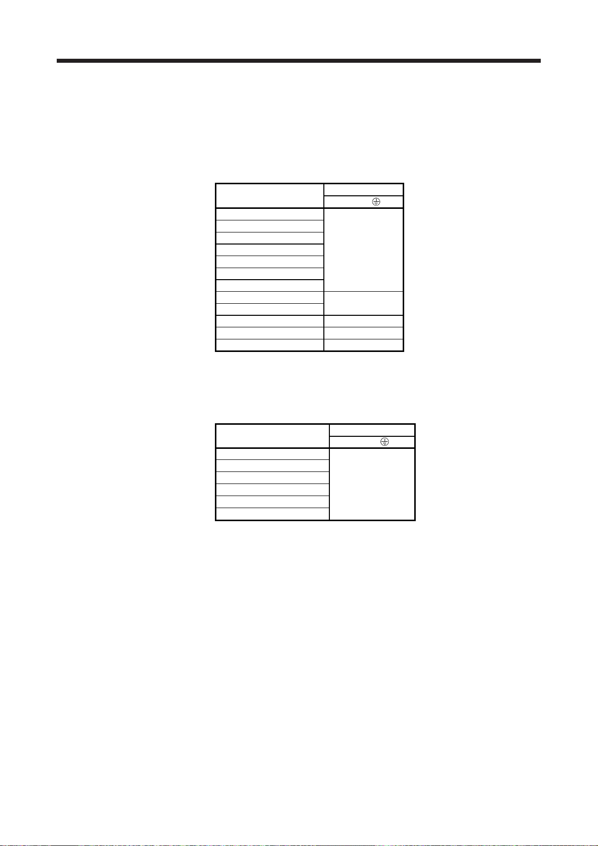
APPENDIX
(2) Selection example of wires
To comply with UL 1004-1 and CSA-C22.2 No. 100, use UL-approved copper wires rated at 75 °C for
wiring.
The following table shows the wire size [AWG] rated at 75 °C, which is used for wiring of TM-RFM, TMRG2M and TM-RU2M series.
(a) TM-RFM series
Note 1. Refer to each servo amplifier instruction manual for crimp terminals used for
2. To comply with UL 508A and NFPA 79, AWG 14 or more is required.
(b) TM-RG2M series and TM-RU2M series
Note. To comply with UL 508A and NFPA 79, AWG 14 or more is required.
Direct drive motor
TM-RFM002C20
TM-RFM004C20
TM-RFM006C20
TM-RFM006E20 16 (Note 2)
TM-RFM012E20
TM-RFM018E20
TM-RFM012G20
TM-RFM048G20
TM-RFM072G20
TM-RFM040J10 16 (Note 2)
TM-RFM120J10 12
TM-RFM240J10 10 (Note 1)
connection with the servo amplifier.
Direct drive motor
TM-RG2M002C30
TM-RU2M002C30
TM-RG2M004E30
TM-RU2M004E30
TM-RG2M009G30
TM-RU2M009G30
Wire [AWG]
U/V/W/
12
Wire [AWG]
U/V/W/
18 (Note)
App. - 7
Page 75

REVISIONS
*The manual number is given on the bottom left of the back cover.
Revision Date * Manual Number Revision
Mar. 2012 SH(NA)030112ENG-A First edition
May 2012 SH(NA)030112ENG-B Chapter 4 (3) The part of diagram is changed.
Feb. 2013 SH(NA)030112ENG-C Section 1.1
Section 2.1 (2)
Section 2.9
Chapter 5
Section 5.4
Chapter 6
Section 6.2.4 (1) to (2)
Section 7.2
Section 7.5
Jan. 2015 SH(NA)030112ENG-D 1-phase 100 V AC of servo amplifier power supply input is added to torque characteristics of
the direct drive motor.
Section 1.1
Section 5.4
Section 6.2.4 (1) to (2)
Section 7.2
Section 7.3
Section 7.4
Sep. 2015 SH(NA)030112ENG-E Torque characteristic at 1-phase 200 V AC input is added.
2. To prevent fire, note the
following
4. Additional instructions
Section 1.1
Section 1.2
Section 6.1.1
Section 6.2.4
Section 7.4
App. 2
App. 4
Feb. 2016 SH(NA)030112ENG-F Model names MR-J4-_GF of servo amplifiers are added.
Section 5.4
Section 7.2
Section 7.3
App. 2
Mar. 2017 SH(NA)030112ENG-G TM-RG2M/TM-RU2M series direct drive motors are added.
4. Additional instructions Partially changed.
Section 1.1 Changed.
Chapter 2 CAUTION is added.
Section 2.2 TM-RG2M/TM-RU2M are added.
Section 2.6 Partially changed.
Section 2.7 Partially changed.
Section 2.9 Partially changed.
Section 2.10 Added.
Section 3.1 TM-RG2M/TM-RU2M are added.
Section 5.3 TM-RG2M/TM-RU2M are added.
Section 6.1 TM-RG2M/TM-RU2M are added.
Section 6.2 POINT is changed.
Section 6.2.3 TM-RG2M/TM-RU2M are added.
Section 6.3 Partially changed.
The part of diagram is changed.
The part of sentences are changed.
The part of sentences are changed.
POINT is added.
A part is newly added, construction of sentences is changed.
POINT is added.
The part of diagram is changed.
The part of table is changed.
The part of diagram is changed.
The diagram is changed.
The table is added.
Note 1 is changed.
The part of table is changed.
Note 4 is changed.
POINT is changed. The sentences are added. The part of
diagram is changed.
Partially added.
Partially added.
The diagram is changed.
Partially changed.
Partially added.
Partially changed.
Partially added and partially changed.
Partially changed.
Added.
Model names are added.
Partially changed.
Model names are added.
Partially added.
Partially changed.
Page 76

Revision Date *Manual Number Revision
Mar. 2017 SH(NA)030112ENG-G Section 7.3 Partially changed.
Chapter 8 Added.
App. 2 Partially changed.
App. 5 Added.
App. 6 Added.
Oct. 2017 SH(NA)030112ENG-H TM-RG2M002C30/TM-RU2M002C30 direct drive motors are added.
4. Additional instructions Partially changed.
Section 2.9 Partially changed.
Section 3.1 Partially changed.
Section 5.3 TM-RG2M002C30/TM-RU2M002C30 are added.
Section 6.1.2 TM-RG2M002C30/TM-RU2M002C30 are added.
Chapter 8 TM-RG2M002C30/TM-RU2M002C30 are added.
App. 6 Partially changed.
This manual confers no industrial property rights or any rights of any other kind, nor does it confer any patent licenses.
Mitsubishi Electric Corporation cannot be held responsible for any problems involving industrial property rights which
may occur as a result of using the contents noted in this manual.
2012 MITSUBISHI ELECTRIC CORPORATION
Page 77

MEMO
Page 78

MELSERVO is a trademark or registered trademark of Mitsubishi Electric Corporation in Japan and/or other countries.
All other product names and company names are trademarks or registered trademarks of their respective companies.
Page 79

Warranty
1. Warranty period and coverage
We will repair any failure or defect hereinafter referred to as "failure" in our FA equipment hereinafter referred to as the "Product"
arisen during warranty period at no charge due to causes for which we are responsible through the distributor from which you
purchased the Product or our service provider. However, we will charge the actual cost of dispatching our engineer for an on-site
repair work on request by customer in Japan or overseas countries. We are not responsible for any on-site readjustment and/or trial
run that may be required after a defective unit are repaired or replaced.
[Term]
The term of warranty for Product is twelve (12) months after your purchase or delivery of the Product to a place designated by you or
eighteen (18) months from the date of manufacture whichever comes first (“Warranty Period”). Warranty period for repaired Product
cannot exceed beyond the original warranty period before any repair work.
[Limitations]
(1) You are requested to conduct an initial failure diagnosis by yourself, as a general rule.
It can also be carried out by us or our service company upon your request and the actual cost will be charged. However, it will not
be charged if we are responsible for the cause of the failure.
(2) This limited warranty applies only when the condition, method, environment, etc. of use are in compliance with the terms and
conditions and instructions that are set forth in the instruction manual and user manual for the Product and the caution label
affixed to the Product.
(3) Even during the term of warranty, the repair cost will be charged on you in the following cases;
(i) a failure caused by your improper storing or handling, carelessness or negligence, etc., and a failure caused by your
2. Term of warranty after the stop of production
(1) We may accept the repair at charge for another seven (7) years after the production of the product is discontinued. The
(2) Please note that the Product (including its spare parts) cannot be ordered after its stop of production.
3. Service in overseas countries
4. Exclusion of loss in opportunity and secondary loss from warranty liability
(1) Damages caused by any cause found not to be the responsibility of Mitsubishi.
(2) Loss in opportunity, lost profits incurred to the user by Failures of Mitsubishi products.
(3) Special damages and secondary damages whether foreseeable or not, compensation for accidents, and compensation for
(4) Replacement by the user, maintenance of on-site equipment, start-up test run and other tasks.
5. Change of Product specifications
6. Application and use of the Product
(1) For the use of our General-Purpose AC Servo, its applications should be those that may not result in a serious damage even if any
(2) Our General-Purpose AC Servo is designed and manufactured as a general purpose product for use at general industries.
SH(NA)030112ENG-H
hardware or software problem
(ii) a failure caused by any alteration, etc. to the Product made on your side without our approval
(iii) a failure which may be regarded as avoidable, if your equipment in which the Product is incorporated is equipped with a
safety device required by applicable laws and has any function or structure considered to be indispensable according to a
common sense in the industry
(iv) a failure which may be regarded as avoidable if consumable parts designated in the instruction manual, etc. are duly
maintained and replaced
(v) any replacement of consumable parts (battery, fan, smoothing capacitor, etc.)
(vi) a failure caused by external factors such as inevitable accidents, including without limitation fire and abnormal fluctuation of
voltage, and acts of God, including without limitation earthquake, lightning and natural disasters
(vii) a failure generated by an unforeseeable cause with a scientific technology that was not available at the time of the shipment
of the Product from our company
(viii) any other failures which we are not responsible for or which you acknowledge we are not responsible for
announcement of the stop of production for each model can be seen in our Sales and Service, etc.
Our regional FA Center in overseas countries will accept the repair work of the Product. However, the terms and conditions of the
repair work may differ depending on each FA Center. Please ask your local FA center for details.
Regardless of the gratis warranty term, Mitsubishi shall not be liable for compensation to:
damages to products other than Mitsubishi products.
Specifications listed in our catalogs, manuals or technical documents may be changed without notice.
failure or malfunction occurs in General-Purpose AC Servo, and a backup or fail-safe function should operate on an external
system to General-Purpose AC Servo when any failure or malfunction occurs.
Therefore, applications substantially influential on the public interest for such as atomic power plants and other power plants of
electric power companies, and also which require a special quality assurance system, including applications for railway companies
and government or public offices are not recommended, and we assume no responsibility for any failure caused by these
applications when used
In addition, applications which may be substantially influential to human lives or properties for such as airlines, medical treatments,
railway service, incineration and fuel systems, man-operated material handling equipment, entertainment machines, safety
machines, etc. are not recommended, and we assume no responsibility for any failure caused by these applications when used.
We will review the acceptability of the abovementioned applications, if you agree not to require a specific quality for a specific
application. Please contact us for consultation.
Page 80

MODEL
DIRECT DRIVEMOTOR
INSTRUCTIONMANUAL
MODEL
CODE
This Instruction Manual uses recycled paper.
SH(NA)030112ENG-H(1710)MEE Printed in Japan Specifications are subject to change without notice.
1CW948
HEAD OFFICE: TOKYO BLDG MARUNOUCHI TOKYO 100-8310
 Loading...