

Mitsubishi TM90SA-6 Datasheet
TM90SA-6
MITSUBISHI THYRISTOR MODULES
TM90SA-6
MEDIUM POWER GENERAL USE
NON-INSULATED TYPE
• IT (AV) Average on-state current ............ 90A
• V
RRM Repetitive peak reverse voltage
................ 300V
• V
DRM Repetitive peak off-state voltage
................ 300V
• TRIPLE ARMS
• Non-Insulated Type
APPLICATION
Welders
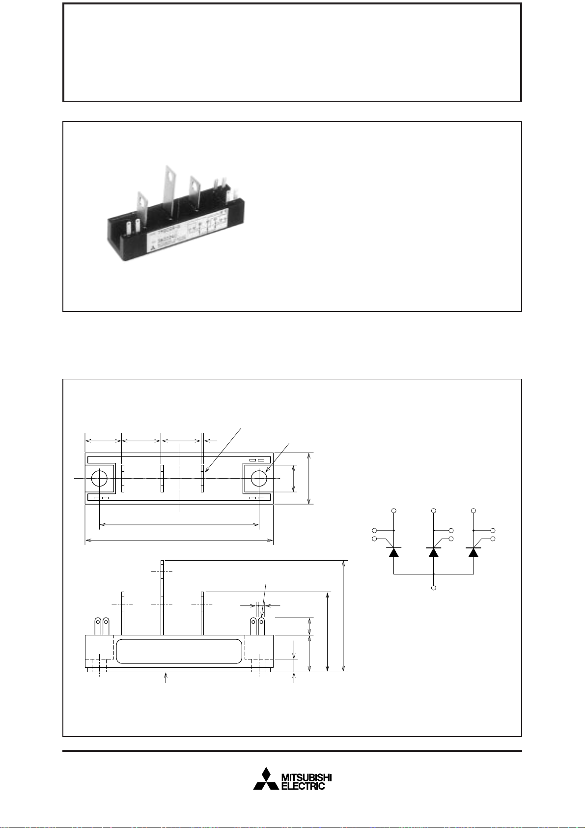
OUTLINE DRAWING & CIRCUIT DIAGRAM Dimensions in mm
3–φ6×7
18
G3K
20
K
3
3
20 1
K
2
80
93.5
LABEL
2
Tab#110,
t=0.5
2–φ6.5
13
6.5
26
9
19
41
56
K
CR
1
K
2
G
2
2
CR
1
K
CR
2
3
A
K
3
K
3
G
3
K2G
K
1
K
1G1
4 2.2
K
1
G
1
A
Feb.1999
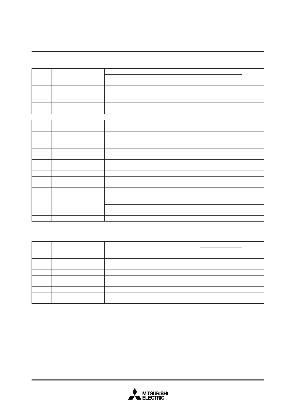
ABSOLUTE MAXIMUM RATINGS
Symbol
RRM
V
VRSM
VR (DC)
VDRM
VDSM
VD (DC)
Repetitive peak reverse voltage
Non-repetitive peak reverse voltage
DC reverse voltage
Repetitive peak off-state voltage
Non-repetitive peak off-state voltage
DC off-state voltage
Parameter
Voltage class
6
300
360
240
300
360
240
MITSUBISHI THYRISTOR MODULES
TM90SA-6
MEDIUM POWER GENERAL USE
NON-INSULATED TYPE
Unit
V
V
V
V
V
V
Symbol
T (RMS)
I
IT (AV)
ITSM
2
t
I
di/dt
GM
P
PG (AV)
VFGM
VRGM
IFGM
Tj
Tstg
RMS on-state current
Average on-state current
Surge (non-repetitive) on-state current
2
t
I
Critical rate of rise of on-state current
Peak gate power dissipation
Average gate power dissipation
Peak gate forward voltage
Peak gate reverse voltage
Peak gate forward current
Junction temperature
Storage temperature
—
Mounting torque
—
Weight
Parameter
for fusing
ELECTRICAL CHARACTERISTICS
Symbol
I
RRM
IDRM
VTM
dv/dt
GT
V
VGD
IGT
Rth (j-c)
Rth (c-f)
Repetitive peak reverse current
Repetitive peak off-state current
On-state voltage
Critical rate of rise of off-state voltage
Gate trigger voltage
Gate non-trigger voltage
Gate trigger current
Thermal resistance
Contact thermal resistance
Parameter
Conditions
Three-phase, half-wave, T
C=126°C
One half cycle at 60Hz, peak value
Value for one cycle of surge current
D=1/2VDRM, IG=1.0A, Tj=150°C
V
Main terminal screw M5
Mounting screw M6
Typical value
Test conditions
j=150°C, VRRM applied
T
j=150°C, VDRM applied
T
j=150°C, ITM=270A, instantaneous meas.
T
j=150°C, VD=2/3VDRM
T
Tj=25°C, VD=6V, RL=2Ω
j=150°C, VD=1/2VDRM
T
Tj=25°C, VD=6V, RL=2Ω
Junction to case (per 1/3 module)
Case to fin, conductive grease applied (per 1/3 module)
Min.
—
—
—
200
—
0.25
15
—
—
Ratings
140
90
1800
1.4 × 10
100
5.0
0.5
10
5.0
2.0
–40~150
–40~125
1.47~1.96
15~20
1.96~2.94
20~30
160
Limits
Typ.
—
—
—
—
—
—
—
—
—
Unit
A
A
A
4
2
s
A
A/µs
W
W
V
V
A
°C
°C
N·m
kg·cm
N·m
kg·cm
g
Max.
20
20
1.15
—
3.0
—
100
0.2
0.3
Unit
mA
mA
V
V/µs
V
V
mA
°C/W
°C/W
Feb.1999
 Loading...