

Mitsubishi SUZ-KA50VA5, SUZ-KA71VA5, SUZ-KA35VA5, SUZ-KA60VA5, SUZ-KA25 Installation Manual
...
Air-Conditioners
SUZ-KA25, KA35, KA50, KA60, KA71VA5
INSTALLATION MANUAL
For safe and correct use, read this manual and the indoor unit installation manual thoroughly before installing
the air-conditioner unit.
INSTALLATIONSHANDBUCH
Aus Sicherheitsgründen und zur richtigen Verwendung vor der Installation die vorliegende Bedienungsanleitung
und die Installationsanleitung der Innenanlage gründlich durchlesen die Klimaanlage.
MANUEL D’INSTALLATION
Avant d’installer le climatiseur, lire attentivement ce manuel, ainsi que le manuel d’installation de l’appareil
intérieur pour une utilisation sûre et correcte.
INSTALLATIEHANDLEIDING
Lees deze handleiding en de installatiehandleiding van het binnenapparaat zorgvuldig door voordat u met het
installeren van de airconditioner begint.
MANUAL DE INSTALACIÓN
Para un uso correcto y seguro, lea detalladamente este manual y el manual de instalación de la unidad interior
antes de instalar la unidad de aire acondicionado.
MANUALE DI INSTALLAZIONE
Per un uso sicuro e corretto, leggere attentamente il presente manuale ed il manuale d’installazione dell’unità
interna prima di installare il condizionatore d’aria.
EΓΧEIPIΔIO OΔHΓIΩN EΓKATAΣTAΣHΣ
Για σωστή και ασφαλή χρήση, διαβάστε προσεκτικά αυτό το εγχειρίδιο καθώς και το εγχειρίδιο εγκατάστασης
της εσωτερικής μονάδας, προτού εγκαταστήσετε τη μονάδα του κλιματιστικού.
MANUAL DE INSTALAÇÃO
Para uma utilização segura e correcta, leia atentamente este manual e o manual de instalação da unidade
interior antes de instalar o aparelho de ar condicionado.
INSTALLATIONSMANUAL
Læs af sikkerhedshensyn denne manual samt manualen til installation af indendørsenheden grundigt, før du
installerer klimaanlægget.
INSTALLATIONSMANUAL
Läs bruksanvisningen och inomhusenhetens installationshandbok noga innan luftkonditioneringen installeras
så att den används på ett säkert och korrekt sätt.
MONTAJ ELKİTABI
Emniyetli ve doğru kullanım için, klima cihazını monte etmeden önce bu kılavuzu ve iç ünite montaj kılavuzunu
tamamıyla okuyun.
FOR INSTALLER
FÜR INSTALLATEURE
POUR L’INSTALLATEUR
VOOR DE INSTALLATEUR
PARA EL INSTALADOR
PER L’INSTALLATORE
ΓΙΑ ΑΥΤΟΝ ΠΟΥ ΚΑΝΕΙ ΤΗΝ ΕΓΚΑΤΑΣΤΑΣΗ
PARA O INSTALADOR
TIL INSTALLATØREN
FÖR INSTALLATÖREN
MONTÖR İÇİN
English
Deutsch
Français
Nederlands
Español
Italiano
Eλληνικά
Português
Dansk
Svenska
Türkçe
Contents
1. The following should always be observed for safety ......................2
2. Selecting the installation location ....................................2
3. Installation diagram ...............................................3
4. Drain piping for outdoor unit ........................................3
5. Refrigerant piping work ............................................4
6. Electrical work ...................................................6
7. Maintenance ....................................................7
8. Pumping down ...................................................8
9. Specications ...................................................8
1. The following should always be observed for safety
• Please provide an exclusive circuit for the air conditioner and do not connect other electrical appliances to it.
• Be sure to read “The following should always be observed for safety” before installing the air conditioner.
• Be sure to observe the cautions specied here as they include important
items related to safety.
The indications and meanings are as follows.
•
Warning:
Could lead to death, serious injury, etc.
Caution:
Could lead to serious injury in particular environments when operated incorrectly.
Warning:
• Do not install it by yourself (customer).
Incomplete installation could cause injury due to re, electric shock, the
unit falling or leakage of water. Consult the dealer from whom you purchased the unit or special installer.
• This appliance is intended to be used by expert or trained users in shops, in
light industry and on farms, or for commercial use by lay persons.
• Install the unit securely in a place which can bear the weight of the unit.
When installed in an insufcient strong place, the unit could fall causing
injured.
• Use the specied wires to connect the indoor and outdoor units securely
and attach the wires rmly to the terminal board connecting sections so the
stress of the wires is not applied to the sections.
Incomplete connecting and xing could cause re.
• Do not use intermediate connection of the power cord or the extension cord
and do not connect many devices to one AC outlet.
It could cause a re or an electric shock due to defective contact, defective
insulation, exceeding the permissible current, etc.
Check that the refrigerant gas does not leak after installation has completed.
•
• Perform the installation securely referring to the installation manual.
Incomplete installation could cause a personal injury due to re, electric
shock, the unit falling or leakage of water.
• Use only specied cables for wiring. The wiring connections must be made
securely with no tension applied on the terminal connections. Also, never
splice the cables for wiring (unless otherwise indicated in this document).
Failure to observe these instructions may result in overheating or a re.
• Perform electrical work according to the installation manual and be sure to
use an exclusive circuit.
• After reading this manual, be sure to keep it together with the instruction
manual in a handy place on the customer’s site.
: Indicates a part which must be grounded.
Warning:
Carefully read the labels afxed to the main unit.
If the capacity of the power circuit is insufcient or there is incomplete electrical work, it could result in a re or an electric shock.
• Attach the electrical part cover to the indoor unit and the service panel to
the outdoor unit securely.
If the electrical part cover in the indoor unit and/or the service panel in the
outdoor unit are not attached securely, it could result in a re or an electric
shock due to dust, water, etc.
• Be sure to use the part provided or specied parts for the installation work.
The use of defective parts could cause an injury or leakage of water due to
a re, an electric shock, the unit falling, etc.
• Ventilate the room if refrigerant leaks during operation.
If the refrigerant comes in contact with a ame, poisonous gases will be
released.
When pumping down the refrigerant, stop the compressor before disconnect-
•
ing the refrigerant pipes. The compressor may burst if air etc. get into it.
• When installing or relocating, or servicing the air conditioner, use only the
specied refrigerant (R410A) to charge the refrigerant lines. Do not mix it
with any other refrigerant and do not allow air to remain in the lines.
If air is mixed with the refrigerant, then it can be the cause of abnormal high
pressure in the refrigerant line, and may result in an explosion and other
hazards.
The use of any refrigerant other than that specied for the system will cause
mechanical failure or system malfunction or unit breakdown. In the worst
case, this could lead to a serious impediment to securing product safety.
Caution:
• Perform grounding.
Do not connect the ground wire to a gas pipe, water pipe arrester or telephone ground wire. Defective grounding could cause an electric shock.
• Do not install the unit in a place where an inammable gas leaks.
If gas leaks and accumulates in the area surrounding the unit, it could cause
an explosion.
• Install a ground leakage breaker depending on the installation place (where
it is humid).
2. Selecting the installation location
2.1. Outdoor unit
• Where it is not exposed to strong wind.
• Where airow is good and dustless.
• Where it is not exposed to rain and direct sunshine.
• Where neighbours are not annoyed by operation sound or hot air.
• Where rigid wall or support is available to prevent the increase of operation sound
or vibration.
• Where there is no risk of combustible gas leakage.
• When installing the unit at a high level, be sure to x the unit legs.
• Where it is at least 3 m away from the antenna of TV set or radio. (Otherwise,
images would be disturbed or noise would be generated.)
• Please install it in an area not affected by snowfall or blowing snow. In areas with
heavy snow, please install a canopy, a pedestal and/or some bafe boards.
• Install the unit horizontally.
2
If a ground leakage breaker is not installed, it could cause an electric shock.
• Perform the drainage/piping work securely according to the installation
manual.
If there is a defect in the drainage/piping work, water could drop from the
unit and household goods could be wet and damaged.
• Fasten a are nut with a torque wrench as specied in this manual.
When fastened too tight, a are nut may broken after a long period and
cause a leakage of refrigerant.
Caution:
Avoid the following places for installation where air conditioner trouble is liable to occur.
• Where there is too much machine oil.
• Salty environment as seaside areas.
• Hot-spring areas.
• Where sulde gas exists.
• Other special atmospheric areas.
The outdoor unit produces condensate during the heating operation. Select
the installation place to ensure to prevent the outdoor unit and/or the grounds
from being wet by drain water or damaged by frozen drain water.
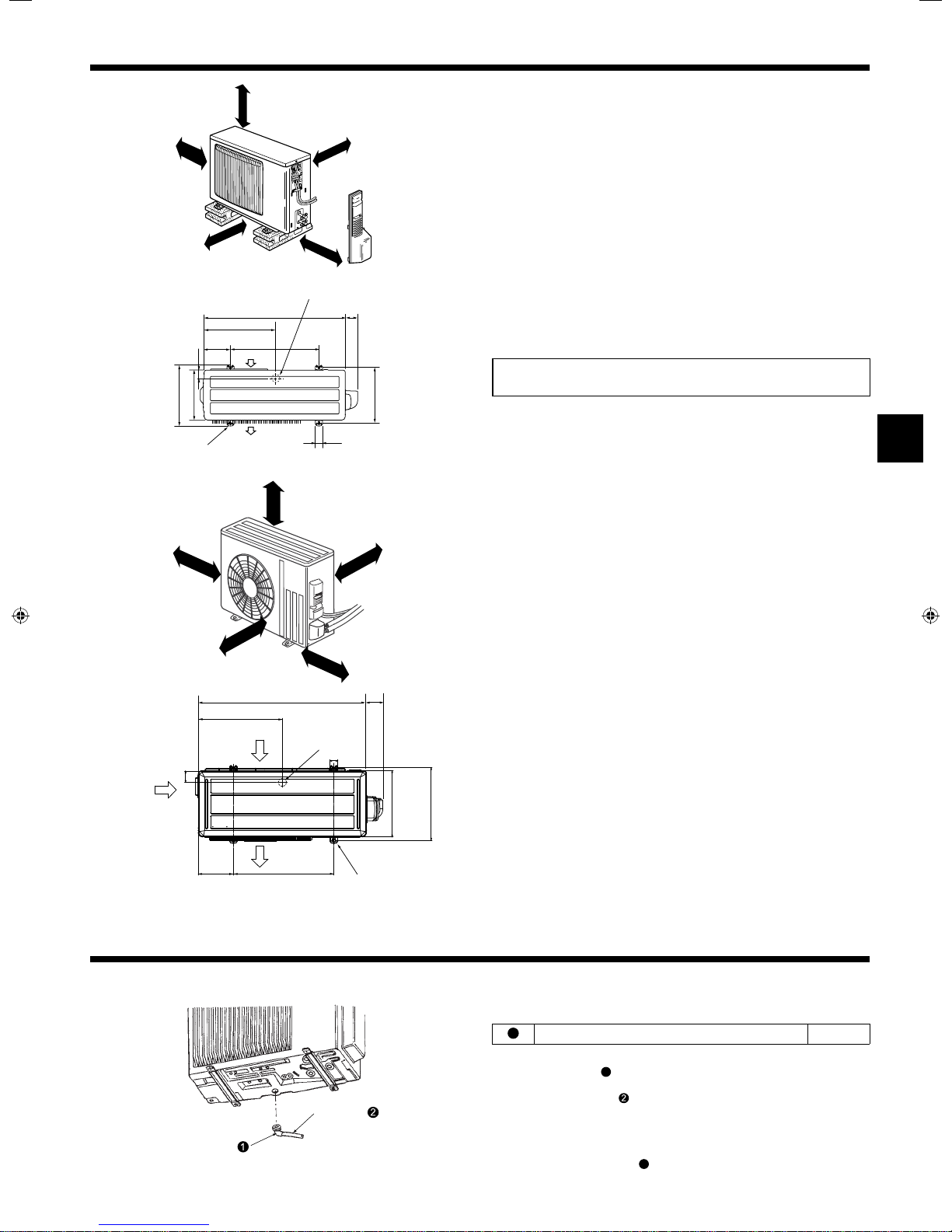
3. Installation diagram
■ SUZ-KA25VA5
SUZ-KA35VA5
2-10 mm × 21 mm slot
■ SUZ-KA50VA5
SUZ-KA60VA5
SUZ-KA71VA5
3.1. Outdoor unit (Fig. 3-1)
C
A
D
Drainage hole ({42)
(In case of Heater models {33)
800
400
344.5
150
44
285
Air inlet
500
Air outlet
A
B
69
304 - 325
40
(mm)
C
A
A
Ventilation and service space
■ SUZ-KA25VA5
SUZ-KA35VA5
100 mm or more
A
B 350 mm or more
C Basically open 100 mm or more without any obstruction in front and on both
sides of the unit.
D 200 mm or more (Open two sides of left, right, or rear side.)
■ SUZ-KA50VA5
SUZ-KA60VA5
SUZ-KA71VA5
100 mm or more
A
B 350 mm or more
C 500 mm or more
When the piping is to be attached to a wall containing metals (tin plated) or metal
netting, use a chemically treated wooden piece 20 mm or thicker between the wall
and the piping or wrap 7 to 8 turns of insulation vinyl tape around the piping.
Units should be installed by licensed contractor accordingly to local code requirement.
Note:
When operating the air conditioner in low outside temperature, be sure to follow the instructions described below.
• Never install the outdoor unit in a place where its air inlet/outlet side may be exposed directly to wind.
• To prevent exposure to wind, install the outdoor unit with its air inlet side facing
the wall.
• To prevent exposure to wind, it is recommended to install a bafe board on the air
outlet side of the outdoor unit.
C
B
81
40
330
2-10 mm × 21 mm slot
Air inlet
840
417.5
Air outlet
500175
Drainage hole
({42)
Air inlet
50
Fig. 3-1
4. Drain piping for outdoor unit (Fig. 4-1)
Drain hose
Drain socket
Fig. 4-1
360
(mm)
4.1. Accessories
Check the following parts before installation.
<Outdoor unit>
1
Drain socket
• Provide drain piping before indoor and outdoor piping connection. (It will be hard
to install drain socket
to drain piping as outdoor unit becomes immovable.)
• Connect the drain hose
shown in the gure for drainage.
• Make sure to provide drain piping with a downhill grade for easy drain ow.
Note:
Do not use the drain socket
makes the fan stop.
if indoor and outdoor piping connection is conducted prior
1
(obtainable at a store, inside diameter: 15 mm) as
in the cold region. Drain may freeze and it
1
1
3
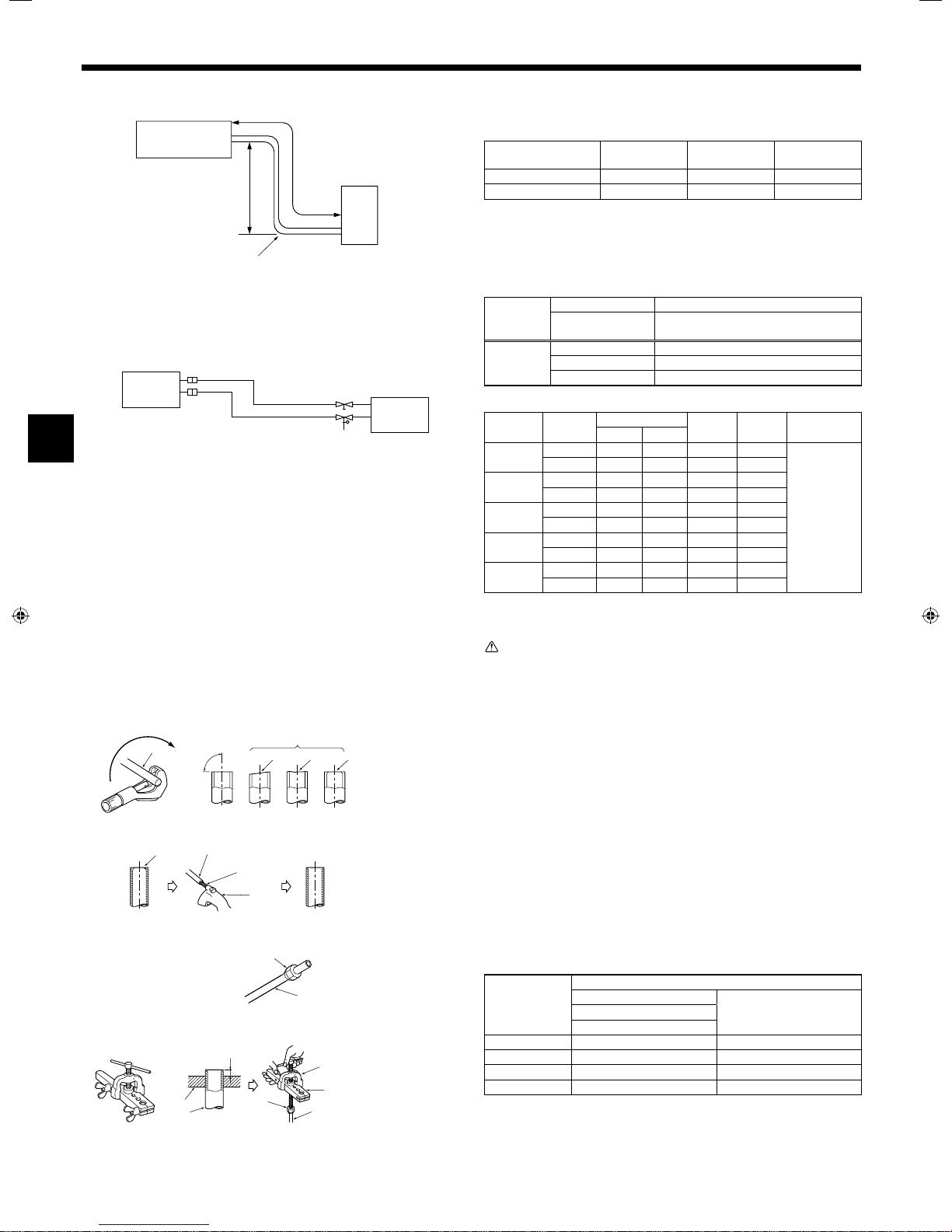
5. Refrigerant piping work
A
(B)
(C)
Fig. 5-1
A
ø9.52
ø12.7
ø15.88
ø6.35
ø9.52
Fig. 5-2
(A)
A Indoor unit
B Outdoor unit
B
A Indoor unit
B Outdoor unit
B
5.1. Refrigerant pipe (Fig. 5-1)
► Check that the difference between the heights of the indoor and outdoor
units, the length of refrigerant pipe, and the number of bends in the pipe are
within the limits shown below.
Models
SUZ-KA25/KA35 Max. 20 m Max. 12 m Max. of 10
SUZ-KA50/KA60/KA71 Max. 30 m Max. 30 m Max. of 10
• Height difference limitations are binding regardless of which unit, indoor or outdoor, is positioned higher.
• Refrigerant adjustment ... If pipe length exceeds 7 m, additional refrigerant
(R410A) charge is required.
(The outdoor unit is charged with refrigerant for pipe length up to 7 m.)
Pipe length
Refrigerant
to be added
(1) Table below shows the specications of pipes commercially available.
Model Pipe
SUZ-KA25
SUZ-KA35
SUZ-KA50
SUZ-KA60
SUZ-KA71
(2) Ensure that the 2 refrigerant pipes are well insulated to prevent condensation.
(3) Refrigerant pipe bending radius must be 100 mm or more.
SUZ-KA25/KA35 type 30 g × (refrigerant piping length (m) -7)
SUZ-KA50/KA60 type 20 g × (refrigerant piping length (m) -7)
For liquid 6.35 1/4 0.8 mm 8 mm
For gas 9.52 3/8 0.8 mm 8 mm
For liquid 6.35 1/4 0.8 mm 8 mm
For gas 9.52 3/8 0.8 mm 8 mm
For liquid 6.35 1/4 0.8 mm 8 mm
For gas 12.7 1/2 0.8 mm 8 mm
For liquid 6.35 1/4 0.8 mm 8 mm
For gas 15.88 5/8 0.8 mm 8 mm
For liquid 9.52 3/8 0.8 mm 8 mm
For gas 15.88 5/8 1.0 mm 8 mm
(A) Pipe length
(one way)
Up to 7 m No additional charge is required.
Exceeding 7 m
SUZ-KA71 type 55 g × (refrigerant piping length (m) -7)
Outside diameter
mm inch
Additional charge is required.
(Refer to the table below.)
(B) Height
difference
Min. wall
thickness
Insulation
thickness
(C) Number of
bends (one way)
Insulation
material
Heat resisting
foam plastic
0.045 specic
gravity
Caution:
Using careful insulation of specied thickness. Excessive thickness prevents
storage behind the indoor unit and smaller thickness causes dew drippage.
a Copper tubes
b Good
a
90°
dcbe f
c No good
d Tilted
e Uneven
f Burred
Fig. 5-3
a
b
c
d
a Burr
b Copper tube/pipe
c Spare reamer
d Pipe cutter
Fig. 5-4
a
a Flare nut
b
b Copper tube
Fig. 5-5
a
b
c
A
e
d
c
b
a Flaring tool
b Die
c Copper tube
d Flare nut
e Yoke
5.2. Flaring work
• Main cause of gas leakage is defect in aring work.
Carry out correct aring work in the following procedure.
5.2.1. Pipe cutting (Fig. 5-3)
• Using a pipe cutter cut the copper tube correctly.
5.2.2. Burrs removal (Fig. 5-4)
• Completely remove all burrs from the cut cross section of pipe/tube.
• Put the end of the copper tube/pipe to downward direction as you remove burrs in
order to avoid burrs drop in the tubing.
5.2.3. Putting nut on (Fig. 5-5)
• Remove are nuts attached to indoor and outdoor unit, then put them on pipe/tube
having completed burr removal.
(not possible to put them on after aring work)
5.2.4. Flaring work (Fig. 5-6)
• Carry out aring work using aring tool as shown at the right.
Pipe diameter
(mm)
6.35 0 - 0.5 9.1
9.52 0 - 0.5 13.2
12.7 0 - 0.5 16.6
15.88 0 - 0.5 19.7
Firmly hold copper tube in a die in the dimension shown in the table at above.
When the tool for R410A is used
A (mm)
Clutch type
Dimension
B
+0
-0.4
(mm)
Fig. 5-6
4
 Loading...