

Page 1
Manual No.'18 • SRK-SM-259
SERVICE MANUAL
INVERTER WALL MOUNTED TYPE
RESIDENTIAL AIR-CONDITIONERS
(Split system, air to air heat pump type)
SRK25ZSP-W
SRK35ZSP-W
SRK45ZSP-W
Page 2

Page 3

'18 • SRK-SM-259
CONTENTS
1. OUTLINE OF OPERATION CONTROL BY MICROCOMPUTER ................... 2
(1) Operation control function by wireless remote control
(2) Unit ON/OFF button
................................................................................. 3
............................. 2
................................................................................. 3(3) Auto restart function
(4) Installing two air-conditioners in the same room
...................................... 3
(5) High power operation ............................................................................... 4
(6) Economy operation
.................................................................................. 4
(7) Air flow direction adjustment .................................................................... 4
(8) Timer operation
........................................................................................ 5
(9) Outline of heating operation ..................................................................... 5
(10) Outline of cooling operation ..................................................................... 7
(11) Outline of automatic operation ................................................................. 7
(12) Protection control function
2. MAINTENANCE DATA
(1) Cautions
................................................................................................. 16
................................................................................. 16
....................................................................... 8
(2) Items to check before troubleshooting ................................................... 16
(3) Troubleshooting procedure
(If the air-conditioner does not run at all)
........ 16
(4) Troubleshooting procedure (If the air-conditioner runs)
......................... 17
(5) Self-diagnosis table ............................................................................... 18
(6) Service mode (Trouble mode access function) ..................................... 19
(7) Inspection procedures corresponding to detail of trouble ...................... 27
(8)
Phenomenon observed after short-circuit, wire breakage on sensor
(9) Checking the indoor electrical equipment
.............................................. 32
.......... 31
(10) How to make sure of wireless remote control ........................................ 33
(11) Outdoor unit inspection points ............................................................... 34
3. ELECTRICAL WIRING
(1) Indoor units
........................................................................................... 37
................................................................................. 37
(2) Outdoor units ........................................................................................ 38
4. PIPING SYSTEM
.......................................................................................... 40
-
-
1
Page 4
'18 • SRK-SM-259
1. OUTLINE OF OPERATION CONTROL BY MICROCOMPUTER
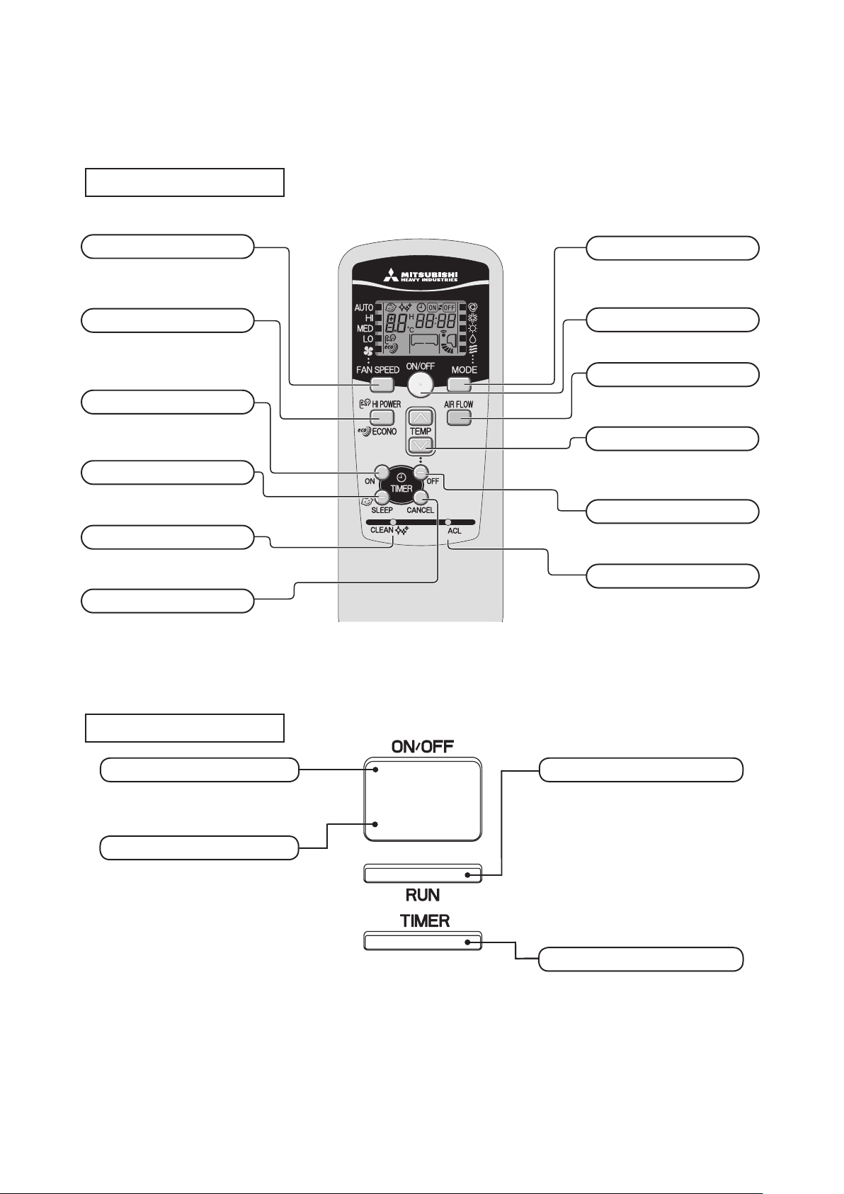
(1) Operation control function by wireless remote control
Remote control
Operation section
◆
FAN SPEED button
Each time the button is pressed, the fan
speed changes.
HI POWER/ECONO button
This button changes the HIGH POWER/
ECONOMY mode.
ON TIMER button
This button selects ON TIMER operation.
SLEEP button
This button selects SLEEP operation.
CLEAN switch
This switch selects the SELF CLEAN
mode.
CANCEL button
This button cancels the ON timer, OFF
timer, and SLEEP operation.
The above illustration shows all controls, but in
•
practice only the relevant parts are shown.
OPERATION MODE select button
Each time the button is pressed, the
mode changes.
ON/OFF (luminous) button
Press to start operation, press again to
stop.
AIR FLOW (UP/DOWN) button
This button changes the air flow
(up/down) direction.
TEMPERATURE button
These buttons set the room temperature.
(These buttons are used for setting the
current time and timer function as well.)
OFF TIMER button
This button selects OFF TIMER
operation.
ACL switch
This switch resets the program to default
state.
Unit display section
Unit ON/OFF button
This button can be used for turning on/off
the unit when a remote control is not available.
Wireless remote control signal receiver
RUN light (green)
• Illuminates during operation.
•
Blinks slowly when SELF CLEAN operation
(3 seconds ON, 1 second OFF).
• Blinks when air flow is stopped to
prevent blowing out of cold air in
heating operation. (1.5 seconds ON,
0.5 seconds OFF)
TIMER light (yellow)
Ⅰlluminates during TIMER operation.
-
-
2
Page 5
'18 • SRK-SM-259
Cut
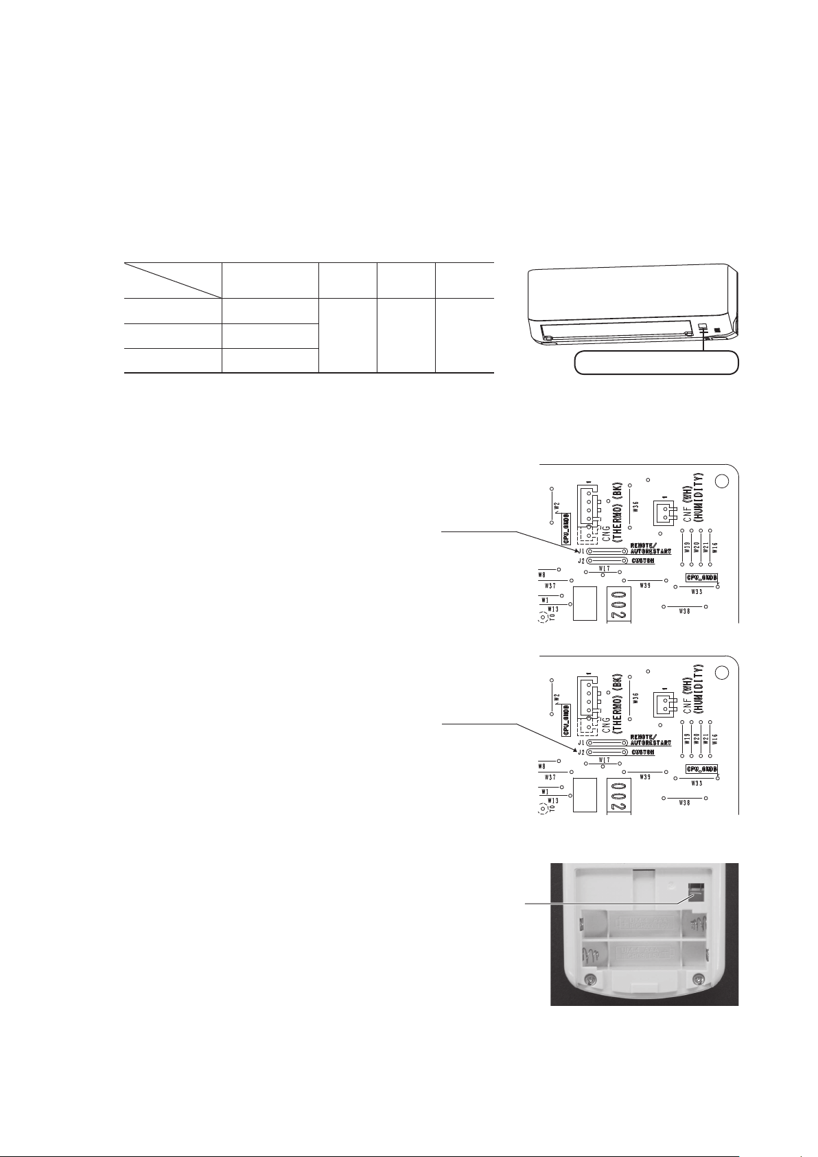
(2) Unit ON/OFF button
When the wireless remote control batteries become weak, or if the wireless remote control is lost or malfunctioning, this
button may be used to turn the unit on and off.
(a) Operation
Push the button once to place the unit in the automatic mode. Push it once more to turn the unit off.
(b) Details of operation
The unit will go into the automatic mode in which it automatically determines, from room temperature (as detected by
sensor), whether to go into the COOL, DRY or Heat modes.
Operation mode
COOL
DRY
HEAT
Function
Room temperature
setting
About 24ºC
About 24ºC
About 26ºC
Fan
speed
Flap
Auto Auto
Timer
switch
Continuous
Unit ON/OFF button
(3) Auto restart function
(a)
Auto restart function records the operational status of the air-conditioner immediately prior to be switched off by a
power cut, and then automatically resumes operations after the power has been restored.
(b) The following settings will be cancelled:
(i) Timer settings
(ii) HIGH POWER operation
Jumper wire (J1)
Notes (1) Auto restart function is set at on when the air-conditioner is shipped from the factory. Consult
with your dealer if this function needs to be switched off.
(2) When power failure ocurrs, the timer setting is cancelled. Once power is resumed, reset the timer.
If the jumper wire (J1) “AUTO RESTART” is cut, auto restart is disabled. (See the diagram at right.)
(3)
(4) Installing two air-conditioners in the same room
When two air-conditioners are installed in the room, set the wireless
remote contrrol and indoor unit as belows to prevent operating air-condi-
tioners with one wireless remote control.
(a) Setting an indoor unit’s printed circuit board
Jumper wire (J2)
(i) Take out the printed circuit board from the control box.
(ii) Disconnect jumper wire (J2) with wire cutters.
(iii) Install a printed circuit board.
(b) Setting a wireless remote control
(i) Pull out the cover and take out batteries.
(ii) Disconnect the switching line next to the battery with wire cutters.
(iii) Insert batteries. Close the cover.
-
-
3
Page 6
'18 • SRK-SM-259
(5) High power operation
(6) Economy operation
Pressing the HI POWER/ECONO button intensifies the operating power and initiates powerful cooling and heating operation for
15 minutes continuously. The wireless remote control displays HIGH POWER mark and the FAN SPEED display disappears.
(a) During the HIGH POWER operation, the room temperature is not controlled. When it causes an excessive cooling and hea-
ting, press the HI POWER/ECONO button again to cancel the HIGH POWER operation.
(b) HIGH POWER operation is not available during the DRY and the ON timer to OFF timer operations.
(c) When HIGH POWER operation is set after ON TIMER operation, HIGH POWER operation will start from the set time.
(d) When the following operation are set, HIGH POWER operation will be canceled.
① When the HI POWER/ECONO button is pressed again.
② When the operation mode is changed.
③ When it has been 15 minutes since HIGH POWER operation has started.
(e) Not operable while the air-conditioner is OFF.
Pressing the HI POWER/ECONO button initiates a soft operation with the power suppressed in order to avoid an excessive
cooling or heating. The unit operates 1.5℃ higher than the setting temperature during cooling or 2.5℃ lower than that during
heating. The wireless remote control displays ECONO mark and the FAN SPEED display disappears.
(a) It will go into ECONOMY operation at the next time the air-conditioner runs in the following cases.
① When the air-conditioner is stopped by ON/OFF button during ECONOMY operation.
② When the air-conditioner is stopped in SLEEP or OFF TIMER operation during ECONOMY operation.
③ When the operation is retrieved from CLEAN operation.
(b) When the following operation are set, ECONOMY operation will be canceled.
① When the HI POWER/ECONO button is pressed again.
② When the operation mode is changed DRY to FAN.
(c) Not operable while the air-conditioner is OFF.
(d) The setting temperature is adjusted according to the following table.
① at the start of operation.
② one hour after the start of operation.
③ two hours after the start of operation.
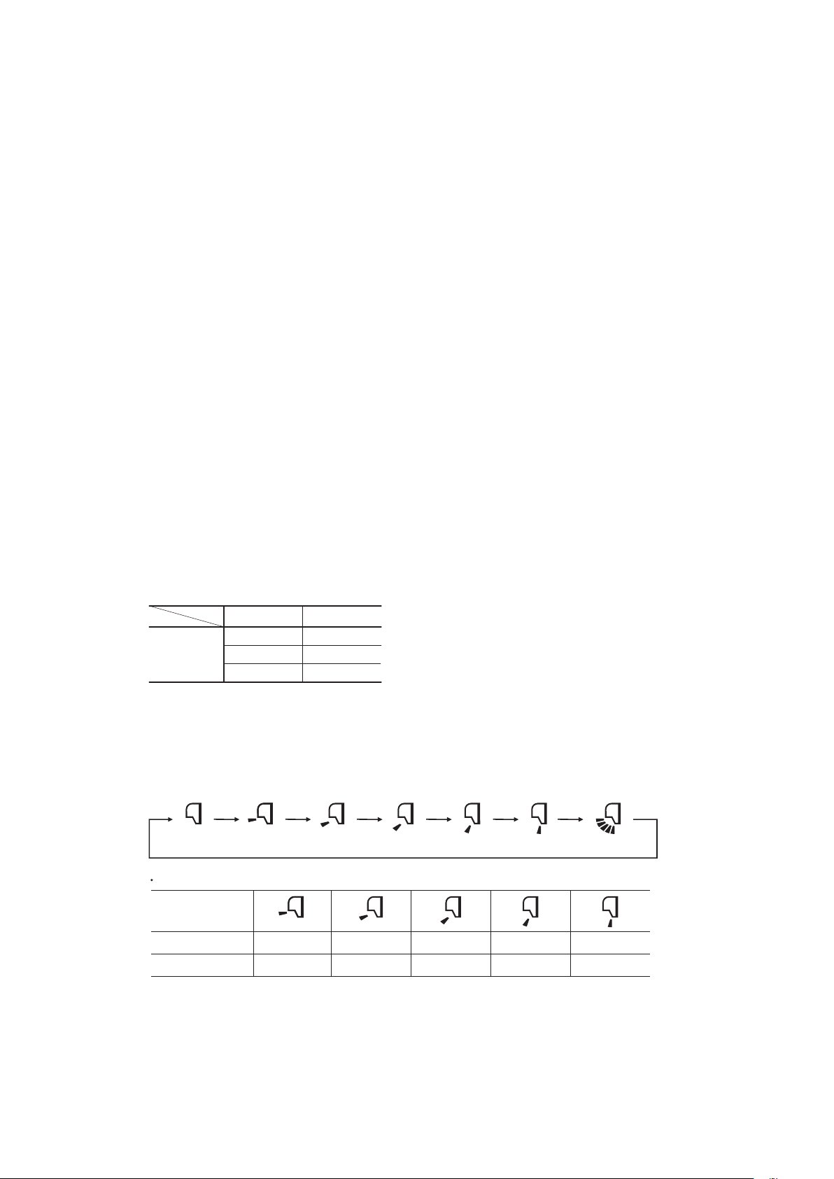
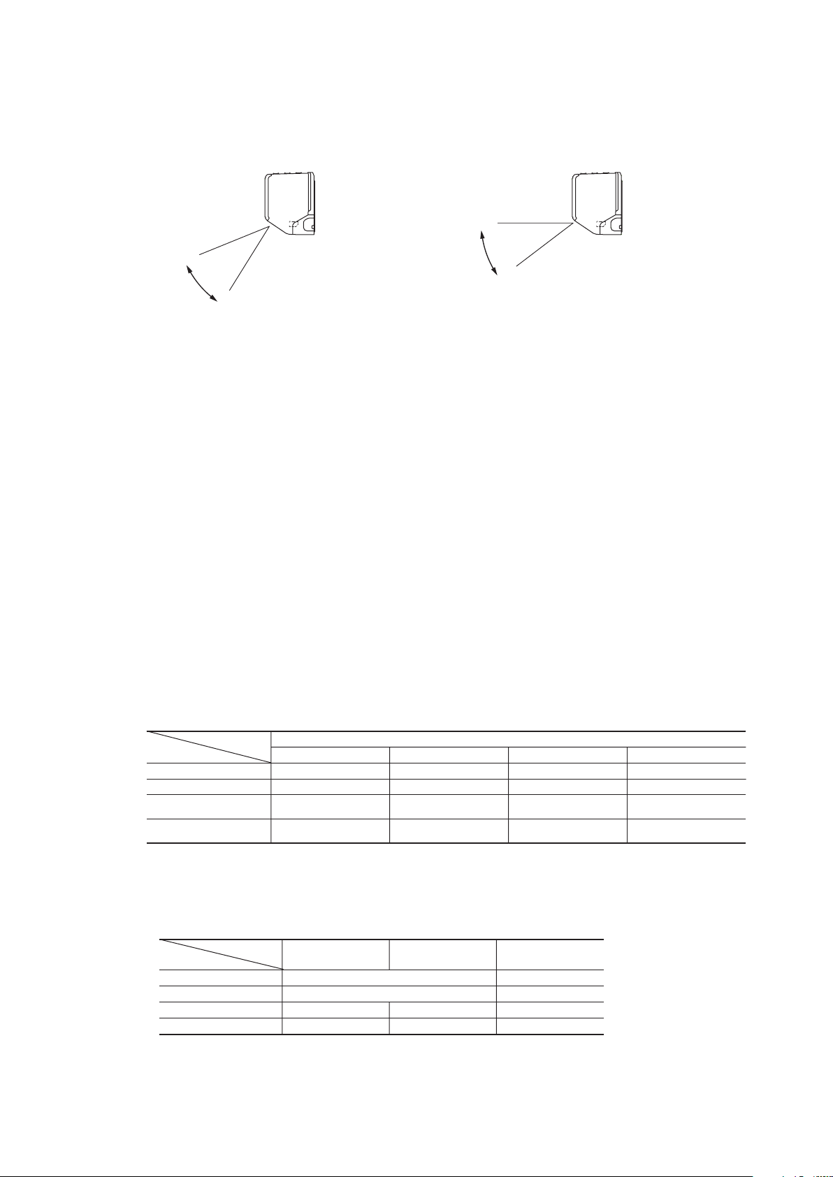
(7) Air flow direction adjustment
Air ow direction can be adjusted with by AIR FLOW
(a) Flap
Item
Temperature
adjustment
Each time when you press the AIR FLOW
Angle of flap from horizontal
Remote control
display
COOL, DRY, FAN
HEAT
Mode
(Flap stopped)
Cooling Heating
①+0.5
②+1.0 ②-2.0
③+1.5 ③-2.5
Approx. 15°
Approx. 25°
①-1.0
Approx. 25°
Approx. 35°
(UP/DOWN) button on the wireless remote control.
(UP/DOWN) button the mode changes as follows.
Approx. 35°
Approx. 50°
Approx. 45°
Approx. 59°
Approx. 59°
Approx. 65°
(Swing)
-
-
4
Page 7
'18 • SRK-SM-259
◆ In HEAT operation ◆ In COOL, DRY, FAN operation
Approx. 65°
ON OFF OFF
ON ON OFF
ON
OFF
(few minutes ON)
OFF
ON ON(HOT KEEP) OFF
OFF
OFF
(3 minutes ON)
OFF
OFF
Thermostat ON Thermostat OFF Defrost Failure
Heating
Compressor
Indoor fan motor
Outdoor fan motor
4-way valve
20-115rps 20-100rps
20
-
115rps 20-100rps
20
-
72rps 20-84rps 20-90rps
20
-
54rps 20-62rps 20-58rps
Model
Fan speed
SRK25ZSP-W SRK35ZSP-W SRK45ZSP-W
AUTO
MED
HI
LO
(b) Swing
Flap moves in upward and downward directions continuously.
Approx.
20°
Approx. 35°
Approx. 59°
(c) Memory flap
When you press the AIR FLOW (UP/DOWN) button once while the ap is operating, it stops swinging at the position.
Since this angle is memorized in the microcomputer, the ap will automatically be set at this angle when the next opera-
tion is started.
(d) When not operating
The ap returns to the position of air ow directly below, when operation has stopped.
(8) Timer operation
(a) Comfortable timer setting (ON timer)
If the timer is set at ON when the operation select switch is set at the cooling or heating, or the cooling or heating in
auto mode operation is selected, the comfortable timer starts and determines the starting time of next operation based
on the initial value of 15 minutes and the relationship between the room temperature at the setting time (temperature of
room temperature sensor) and the setting temperature.
(b) Sleep timer operation
Pressing the SLEEP button causes the temperature to be controlled with respect to the set temperature.
(c) OFF timer operation
The Off timer can be set at a specic time (in 10-minute units) within a 24-hour period.
(9) Outline of heating operation
(a) Operation of major functional components in heating mode
(b) Details of control at each operation mode (pattern)
(i) Fuzzy operation
Deviation between the room temperature setting correction temperature and the suction air temperature is calculated in
accordance with the fuzzy rule, and used for control of the air capacity and the compressor speed.
When the defrost operation, protection device, etc. is actuated, operation is performed in the corresponding mode.
-
-
5
Page 8

(ii) Hot keep operation
Outdoor heat exchanger temperature (
TH1
-20
-25
-20 -15 -10 -5 0 5 10
-15
-10
-5
0
Outdoor air temperature (℃)
TH2
Outdoor heat exchanger temperature (℃)
Defrost operation
start
Defrost operation start temperature
Model DXK15Z6-S
1) Fuzzy operation
2) Hot keep operation
ON OFF
ON ON
ON
OFF
(few minutes ON)
ON ON(HOT KEEP)
OFF
OFF
(3 minutes ON)
OFF
OFF
Thermostat ON Thermostat OFF Failure
Heating
Compressor
Indoor fan motor
Outdoor fan motor
4-way valve
(i)
1)
2)
3)
4)
−
≧
−
≦ <
30~115rps
30~115rps
30~76rps
30~46rps
SRK35ZJ-S
23~106rps
23~106rps
23~78rps
23~50rps
SRK50ZJ-S
30~115rps
30~115rps
30~72rps
30~42rps
SRK25ZJ-S
30~115rps
30~115rps
30~66rps
30~40rps
SRK20ZJ-S
Model
Fan speed
Auto
MED
HI
LO
(model DXK12 : 45)
35
35
(model DXK12 : 45)
(model DXK15 : ≧ −2 ࠉ) (model DXK15 : 10 ࠉ)
(model DXK15 : ≧
−2
ࠉ)
5)
<
− −
−
−
1) 2) 3) 5)
(model DXK15 : +10 ࠉ)
higher
met.
(model SRK50 : 35)
(model SRK50 : 35)
'09•SRK-DB-087D
(16)ࠉOutline of heating operation
(a) Operation of major functional components in heating mode
(b) Details of control at each operation mode (pattern)
(i) Fuzzy operation
(ii) Hot keep operation
ON OFF
ON ON
ON
OFF
(few minutes ON)
ON ON(HOT KEEP)*
OFF
OFF
(3 minutes ON)
OFF
OFF
Thermostat ON Thermostat OFF Failure
Heating
Compressor
Indoor fan motor
Outdoor fan motor
4-way valve
(c) Defrost operation
(i)
1)
2)
3)
4)
5)
−
Model
Fan speed
Auto
MED
HI
LO
ULO
*It can be set the indoor fan motor off or the heating thermostat OFF with connecting a wired remote control.
In the case, indoor air temperature is detected by sensor on the wired remote control.
During the heating operation, the indoor fan speed can be controlled based on the temperature of the indoor heat
exchanger (Th2) to prevent blowing out of cold air.
are satisfied.)
(Total compressor operation time)
After finish of defrost operation
C or less for 3 minutes continuously.
(Total compressor operation time)
20~115rps
20~115rps
20~86rps
20~70rps
20~44rps
SRK20ZS-S
20~115rps
20~115rps
20~104rps
20~84rps
20~54rps
SRK25ZS-S
20~115rps
20~115rps
20~108rps
20~96rps
20~60rps
SRK35ZS-S
23~106rps
23~106rps
23~82rps
23~70rps
23~37rps
SRK50ZS-S
is as following.
During the heating operation, the indoor fan speed can be controlled based on the temperature of the indoor heat ex-
changer (Th2) to prevent blowing of cold air.
(c) Defrost operation
(i)
1)
(model SRK35 : 45)
35
2)
35
(model SRK35 : 45)
3)
-
4)
follows.
TH2
•0
•
•TH2
TH2: TH2
℃≦
℃≦
15
-
<
0
<
TH2
: TH2
℃
15
-
-
℃
TH1
≧
: TH2
TH1
-
7
-
≧
Models SRK25, 35, 45ZSP-W
(ii)
1)
2)
0
℃)
-5
-10
TH1
-15
-20
-25
In case satisfied all of following conditions.
-20 -15 -10 -5 0 5 10
• Connect compressor speed 0 rps 10 times or more.
• Satisfy 1), 2) and 3) conditions above.
• Outdoor air temperature is 3°C or less.
Defrost operation start temperature
Outdoor air temperature (℃)
and 30 seconds).
●
Defrost operation
Heating operation
Depends on an operation condition, the time can be longer than 7 minutes.
≦
, TH1
℃
2/15
≧
TH1
, TH1
℃
5
-
Defrost operation
start
TH2
operation
(Mode SRK45: Max.17 minutes and 30 seconds)
Total
Total
or less
℃
7
-
13/15
≦
, TH1
℃
7
+
TH2
×
℃
5
+
TH2
≦
Max. 16 minutes and 50 seconds
-
6
-
'18 • SRK-SM-259
satisfied.
℃
7
-
TH2
×
satisfied.
(SRK45 : 10 )
16
minutes and 50 seconds (model SRK45 : 17 minutes
2-7 minutes
Hot keep operation
is as
Page 9
27.5
25.5
18.0
18
30
(10) Outline of cooling operation
ON OFF OFF
OFF OFF OFF
ON
OFF
(few minutes ON)
OFF
(few minutes ON)
ON ON ON
Thermostat ON Thermostat OFF Failure
Cooling
Compressor
Indoor fan motor
Outdoor fan motor
4-way valve
15-74rps 20-97rps
15-74rps
15-98rps
15-98rps 20-97rps
15-52rps 15-74rps 20-72rps
15-38rps 15-46rps 20-44rps
Model
Fan speed
SRK25ZSP-W SRK35ZSP-W SRK45ZSP-W
AUTO
MED
HI
LO
(a) Operation of major functional components in cooling mode
(b) Detail of control in each mode (Pattern)
(i) Fuzzy operation
During the fuzzy operation, the air ow and the compressor speed are controlled by calculating the difference between
the room temperature setting correction temperature and the suction air temperature.
'18 • SRK-SM-259
(11) Outline of automatic operation
(a) Determination of operation mode
The unit checks the indoor air temperature and the outdoor air temperature, determines the operation mode, and then
begins in the automatic operation.
Cooling
Indoor air temperature (˚C)
A
Heating
Outdoor air temperature (˚C)
Dehumidifying
(b) The unit checks the temperature every hour after the start of operation and, if the result of check is not same as the pre-
vious operation mode, changes the operation mode.
(i) If the setting temperature is changed with the remote control, the operation mode is judged immediately.
(ii) When both the indoor and the outdoor air temperatures are in the range “A”, cooling or heating is switched depending
on the difference between the setting temperature and the indoor air temperature.
(iii) When the operation mode has been judged following the change of setting temperature with the remote control, the hour-
ly judgment of operation mode is cancelled.
(c) When the unit is started again within one hour after the stop of automatic operation or when the automatic operation is
selected during heating, cooling or dehumidifying operation, the unit is operated in the previous operation mode.
(d) Setting temperature can be adjusted within the following range. There is the relationship as shown below between the
signals of the wireless remote control and the setting temperature.
Signals of wireless remote control (Display)
Setting
temperature
Cooling
Dehumidifying
Heating
–6 –5 –4 –3 –2 –1
18 19 20 21 22 23 24 25 26 27 28 29 30
19 20 21 22 23 24 25 26 27 28 29 30 31
20 21 22 23 24 25 26 27 28 29 30 31 32
0 +1 +2 +3 +4 +5 +6
±
(e) When the unit is operated automatically with the wired remote control connected, the cooling operation is controlled ac-
cording to the display temperatures while the setting temperature is compensated by +1˚C during dehumidifying or by
2˚C during heating.
+
-
-
7
Page 10

(12) Protection control function
(a) Dew prevention control Ⅰ [Cooling]
Prevents dewing on the indoor unit.
(i) Operating conditions
When the following conditions have been satised.
1) Humidity is 78% or higher.
(ii) Contents of operation
Maximum compressor speed
SRK25ZSP-W
SRK35ZSP-W
SRK45ZSP-W
68 rps
73 rps
87 rps
(iii) Reset condition
When either of the following condition is satised.
1) Humidity is 73% or less.
2) Dew prevention control Ⅱ has been satised.
(b) Dew prevention control Ⅱ [Cooling]
Prevents dewing on the indoor unit.
(i) Operating conditions
When the following conditions have been satised for more than 30 minutes after starting operation
1) Compressor speed is 32 rps or higher. (SRK25, 35)
2) Humidity is 68% or higher. (SRK45 : 60%)
(ii) Contents of operation
1) Air capacity control
'18 • SRK-SM-259
Model
Item
Upper limit of compressor speed
LO
SRK25,35ZSP-W SRK45ZSP-W
RangeA: 41rps, RangeB: 41rps RangeA: 57rps, RangeB: 39rps
Indoor fan 4th speed (SRK35 : 5th speed)
AUTO,HI,MED
Upper limit of compressor speed
Indoor fan
RangeA: 41rps, RangeB: 41rps RangeA: 57rps, RangeB: 39rps
Adaptable to compressor
speed (Lower limit 4th speed)
Note (1) Ranges A and B are as shown below.
Range B
Range A
68
73
Humidity(%)
2) When this control has continued for more than 30 minutes continuously,the following wind direction control is per-
formed.
a) When the vertical wind direction is set at other than the vertical swing,the aps change to the horizontal position.
b) When the horizontal wind direction is set at other than the horizontal swing,the louver changes to the vertical po-
sition.
(iii) Reset condition
When any of followings is satised.
1) Humidity is less than 63%. (SRK45 : 55%)
-
-
8
Page 11
'09•SRK-DB-087D
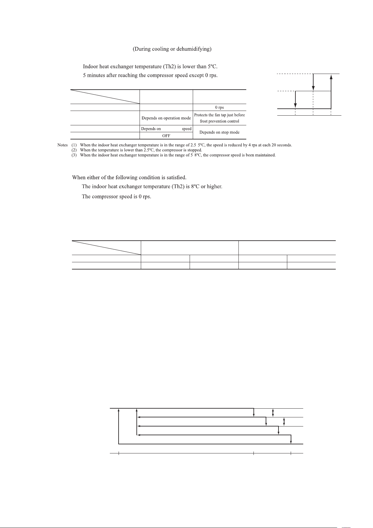
(c) Frost prevention control
A
B
C
Outdoor heat exchanger temperature(°C)
8rps
(1)
8rps
(1)
0rps
After lapse of 20 sec. or over
(3)
After lapse of 20 sec. or over
(3)
After lapse of 20 sec. or over
(3)
(Example) Fuzzy
(i) Operating conditions
1)
2)
(ii) Detail of anti-frost operation
Indoor heat exchanger
Item
Lower limit of compressor speed
Indoor fan
Outdoor fan
4-way valve
temperature
(iii) Reset conditions
1)
2)
5°C or lower 2.5°C or lower
22rps (SRK45 : 23 rps)
compressor
-
-
'18 • SRK-SM-259
compressor
speed
Lower
limit
speed
0 rps
2.55 8
Indoor heat exchanger
temperature (ºC)
(d) Cooling overload protective control
(i) Operating conditions
When the outdoor air temperature (TH2) has become continuously for 30 seconds at 41ºC or more, or 47ºC or more
with the compressor running, the lower limit speed of compressor is brought up.
Model
Item
Outdoor air temperature
Lower limit speed
SRK25, 35ZSP-W SRK45ZSP-W
41°C or more 47°C or more 41°C or more 47°C or more
30 rps 45 rps 27 rps 35 rps
(ii) Detail of operation
1) The outdoor fan is stepped up by 3 speed step. (Upper limit; 8th speed.)
2) The lower limit of compressor speed is set to 30 or 45(model SRK45 : 27 or 35) rps. However, when the thermo
OFF, the speed is reduced to 0 rps.
(iii) Reset conditions
When either of the following condition is satised.
1) The outdoor air temperature is lower than 40ºC.
2) The compressor speed is 0 rps.
(e) Cooling high pressure control
(i) Purpose
Prevents anomalous high pressure operation during cooling.
(ii) Detector
Outdoor heat exchanger sensor (TH1)
(iii) Detail of operation
-
-
9
Page 12

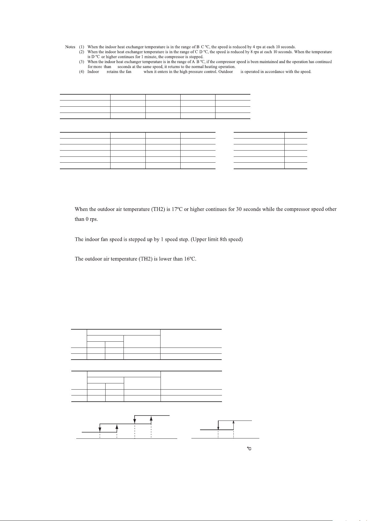
Notes (1) When the outdoor heat exchanger temperature is in the range of B-C ºC, the speed is reduced by 8 rps at each 20 seconds.
'09•SRK-DB-087D
(i) Operating conditions
(e) Cooling low outdoor air temperature protective control
(i) Operating conditions
(ii) Detail of operation
When the outdoor air temperature (TH2) is 22°C or lower continues for 20 seconds while the compressor speed is other than 0 rps.
Compressor speed: Upper/lower limit (rps)
Lower 3Upper 2Lower 2
Lower 1
Range BRange A
Upper 1Upper 3
50504430
50
445044
60
6027
Release
Release
50
SRK25, 35
SRK45
1) It controls the upper and lower limit values for the compressor speed according to the following table.
2) It checks the outdoor temperature (TH2) once every hour to judge the operation range.
'09•SRK-DB-087D
(2) When the temperature is C ºC or higher, the compressor is stopped.
(3) When the outdoor heat exchanger temperature is in the range of A-B ºC, if the compressor speed is been maintained and the operation has
●
Temperature list
Outdoor air temperature
Outdoor air temperature <
continued for more than 20 seconds at the same speed, it returns to the normal cooling operation.
SRK25, 35 SRK45
>
=
32 ºC
32 ºC
A B C A B C
53 58 63 48 53 55
40 43 46 53 58 63
(f) Cooling low outdoor air temperature protective control
'18 • SRK-SM-259
Upper limit 50 rps
ON
Lower limit 50ࠝ44ࠞ rps
EF
First time
After the
second times
Upper limit 50 rps
ON
Lower limit 44 rps
Outdoor air temperature (°C)
(iii) Reset conditions
1)
2)
(g)
Heating high pressure control
(i) Purpose
(ii) Detector
Upper limit 60 rps
ON
Lower limit 30ࠝ27ࠞ rps
CDAB
(Models SRK25, 35)
Outdoor air temperature (˚C)
ABCDEF
OFF
First time
After the
second times
Range A
Range B
Indoor air temperature ( Υ
2624
)
, E, F (Model SRK45)
Outdoor air temperature (˚C)
E FABCD
0
5721691911252228
25
(iii) Detail of operation
(Example) Fuzzy
After lapse of 10 sec. or over
After lapse of 10 sec. or over
After lapse of 10 sec. or over
A
Indoor heat exchanger temperature(°C)
(3)
(3)
lower limit
(3)
speed 30(35) rps
B
4rps
(1)
(1)
4rps
C
8rps
(2)
8rps
(2)
0rps
D
-
-
10
Page 13
'09•SRK-DB-087D
CDAB
OFF
EF
Upper limit 50 rps
Lower limit 44 rps
ON
ON
Upper limit 50 rps
Lower limit 50ࠝ44ࠞ rps
ON
Upper limit 60 rps
Lower limit 30ࠝ27ࠞ rps
Outdoor air temperature (°C)
Heating high pressure control
A
B
C
D
Indoor heat exchanger temperature(°C)
4rps
(1)
8rps
(2)
8rps
(2)
4rps
(1)
0rps
-
-
After lapse of 10 sec. or over
(3)
After lapse of 10 sec. or over
(3)
After lapse of 10 sec. or over
(3)
lower limit
speed 30(35) rps
First time
After the
second times
Outdoor air temperature (˚C)
ABCDEF
1)
2)
(Models SRK25, 35)
First time
After the
second times
Outdoor air temperature (˚C)
E FABCD
, E, F (Model SRK45)
0
5721691911252228
25
2624
Indoor air temperature ( Υ
)
Range A
Range B
'09•SRK-DB-087D
(h) Heating overload protective control
10
fan fan
●
Temperature list
Models SRK25, 35 Unit : ºC
RPSmin < 50
<
50
RPSmin < 92
=
92
<
RPSmin
=
<
=
115
speed
A B C D
47 52 54 55
47.5 55 57 61
47.5-39.0 55.0-40.0 57.0-42.0 61
-
'18 • SRK-SM-259
Model SRK45 Unit : ºC Unit : ºC
RPSmin < 30
<
30
RPSmin < 40
=
<
40
RPSmin < 80
=
<
80
RPSmin < 90
=
<
90
RPSmin < 100
=
(i) Indoor unit side
1) Operating conditions
2) Detail of operation
3) Reset conditions
(ii) Outdoor unit side
1) Operating conditions
When the outdoor air temperature (TH2) is 22 (11 or 20)ºC or higher continues for 30 seconds while the compressor
speed other than 0 rps.
2) Detail of operation
Upper and lower limits of compressor speed and the outdoor unit fan speed are restricted.
Models SRK25,35
ON1
ON2
Model SRK45
ON1
ON2
A B C
45 49 50
45-49 49-55 50-57
49 55 57
49-48 55-53 57-55
48-37 53-42 55-44
Upper limit
Upper limit
Compressor command speed (rps)
Lower limit
Range A Range B
- - - -
40 Release 60 2nd speed
Compressor command speed (rps)
Lower limit
Range A Range B
35 Release 85 It depends on compressor speed
35 35 55 2nd speed
Outdoor fan speed
Outdoor fan speed
RPSmin < 35
<
35
RPSmin < 40
=
<
40
RPSmin < 80
=
<
80
RPSmin < 95
=
<
95
RPSmin < 100
=
D
55.5
55.5-62
62
62-56
56-50.5
Protective
control
Normal
operation
OFF
ON1
10
Outdoor air temperature(°C)
3) Reset conditions
When the outdoor air temperature drops below 19 (13)ºC.
Note (1) Values in ( ) are for the model SRK45.
22 (20)21 (19)11
ON2
Range A
Range B
Indoor air temperature ( Υ
2321
)
-
-
11
Page 14

b) Detail of operation
c) Reset conditions:
10 11 19 20
Normal operation
Protective control ON1
Protective control ON2
Outdoor air temperature(°C)
21 22
Normal operation
Protective
control
Outdoor air temperature(°C)
• Model 50
i)
ii)
iii)
iv)
Taking the upper limit of compressor command speed range at 60 rps, if the output speed obtained with the fuzzy
calculation exceeds the upper limit, the upper limit value is maintained.
The lower limit of compressor command speed is set to 40 rps and even if the calculated result becomes lower than
that after fuzzy calculation, the speed is kept to 40 rps. However, when thethermo becomes OFF, the speed is
reduced to 0 prs.
rps.
a) Operating conditions :
b) Detail of operation
When the outdoor air temperature (TH2) is 11ºC or higher continues for 30 seconds while
the compressor command speed other than 0 rps.
i)
ii)
iii)
iv)
Taking the upper limit of compressor command speed range at 78 rps, if the output speed obtained with the fuzzy
calculation exceeds the upper limit, the upper limit value is maintained.
The lower limit of compressor command speed is set to 30 rps and even if the calculated result becomes lower than
that after fuzzy calculation, the speed is kept to 30 rps. However, when thethermo becomes OFF, the speed is
reduced to 0 prs.
rps.
.
c) Reset conditions:
.
30
Protective
control
NO1
NO2
Item
Compressor command speed
Low limit
30 rps
30 rps
Upper limit
78 rps
51 rps
It depends on compressor command speed
Outdoor fan speed
2nd
10
(i) Heating low outdoor temperature protective control
(i) Protective control I
1) Operating conditions
2 (-8)
lower
'18 • SRK-SM-259
2) Detail of operation
Models SRK25, 35
-10 -8 204
Outdoor air temperature(°C )
3) Reset conditions
a)
b)
Note (1) Values in ( ) are for the model SRK35.
(j) Compressor overheat protection
(i) Purpose
It is designed to prevent deterioration of oil, burnout of motor coil and other trouble resulting from the compressor over-
heat.
(ii) Detail of operation
1) Speeds are controlled with temperature detected by the sensor mounted on the discharge pipe.
(Example) Fuzzy
changed as shown in the figure below.
Lower limit 45(55) rps
Lower limit 40 rps
Lower limit 38(40) rps
Normal operation
Model SRK45
-8 -6
Outdoor air temperature(°C )
Lower limit 27 rps
Normal operation
4 (-6)
After lapse of 60 seconds. or over
After lapse of 60 seconds. or over
After lapse of 60 seconds. or over
(3)
(3)
(3)
(1)
4 rps
Lower limit
4 rps
(4)
0 rps
90 100 110
Discharge pipe temperature (˚C)
Notes (1) When the discharge pipe temperature is in the range of 100 to 110 ºC, the speed is reduced by 4 rps.
(2) When the discharge pipe temperature is raised and continues operation for 20 seconds without changing, then the speed is reduced again by 4
rps.
(3) If the discharge pipe temperature is in the range of 90-100ºC even when the compressor speed is maintained for 60 second when the tempera-
ture is in the range of 90-100ºC, the speed is raised by 1 rps and kept at that speed for 60 second. This process is repeated until the compres-
sor speed is reached.
(4) Lower limit speed
Cooling Heating
Models SRK25, 35
Model SRK45
15 rps 20 rps
20 rps 30rps
-
-
12
Page 15

'18 • SRK-SM-259
(p) Rotor lock
2) If the temperature of 110ºC is detected by the sensor on the discharge pipe, then the compressor will stop immediately.
When the discharge pipe temperature drops and 3 minutes has elapsed, the unit starts again within 1 hour but there
is no start at the third time.
(k) Current safe
(i) Purpose
Current is controlled not to exceed the upper limit of the setting operation current.
(ii) Detail of operation
Input current to the converter is monitored with the current sensor xed on the printed circuit board of the outdoor
unit and, if the operation current value reaches the limiting current value, the compressor speed is reduced.
If the mechanism is actuated when the compressor speed is less than 30 rps, the compressor is stopped immediately.
Operation starts again after 3 minutes.
(l) Current cut
(i) Purpose
Inverter is protected from overcurrent.
(ii) Detail of operation
Output current from the inverter is monitored with a shunt resistor and, if the current exceeds the setting value, the
compressor is stopped immediately. Operation starts again after 3 minutes.
(m) Outdoor unit failure
This is a function for determining when there is trouble with the outdoor unit during air-conditioning.
The compressor is stopped if any one of the following in item (i), (ii) is satised. Once the unit is stopped by this func-
tion, it is not restarted.
(i) When the input current is measured at 1 A or less for 3 continuous minutes or more.
(ii) If the outdoor unit sends a 0 rps signal to the indoor unit 3 times or more within 20 minutes of the power being turned on.
(n) Indoor fan motor protection
When the air-conditioner is operating and the indoor fan motor is turned ON, if the indoor fan motor has operated at 300
-1
or under for more than 30 seconds, the unit enters rst in the stop mode and then stops the entire system.
min
(o) Serial signal transmission error protection
(i) Purpose
(ii) Detail of operation
(q) Outdoor fan motor protection
min
-1
-
-
13
Page 16

(p) Rotor lock
(q) Outdoor fan motor protection
(r) Outdoor fan control at low outdoor temperature
(i)
min
-1
Cooling
1) Operating conditions
2) Detail of operation
Outdoor temperature > 10˚C
<
Outdoor temperature
=
10˚C
a)
b)
-
'18 • SRK-SM-259
Outdoor fan
-
c)
3) Reset conditions
a)
b)
(ii)
Heating
1) Operating conditions
2) Detail of operation
model
SRK45 : 8th speed)
SRK25, 35
ON1
ON2
Values in ( ) are for the model SRK35.
Th1<21℃
8th speed
9th(8th) speed
>
21℃
Th1
=
8th speed
8th speed
24
(model SRK45:0 )
; models SRK25, 35 : refer to belows,
ON2
ON1
OFF
-1 1 4 6
Outdoor air temperature(°C )
3) Reset conditions
a)
b)
(model SRK45:2 )
-
-
14
Page 17

(q) Outdoor fan motor protection
(r) Outdoor fan control at low outdoor temperature
Cooling
1) Operating conditions
2) Detail of operation
3) Reset conditions
Heating
1) Operating conditions
2) Detail of operation
3) Reset conditions
Outdoor temperature > 10˚C
Outdoor temperature
<
=
10˚C
Outdoor fan
a)
b)
a)
b)
a)
b)
c)
(i)
(ii)
Values in ( ) are for the model SRK35.
(model SRK45:0 )
min
-1
-
-
(model SRK45:2 )
; models SRK25, 35 : refer to belows,
model
SRK45 : 8th speed)
Th1<21℃
SRK25, 35
8th speed
9th(8th) speed
Th1
21℃
8th speed
8th speed
ON1
ON2
>
=
-1 1 4 6
Outdoor air temperature(°C )
ON1
ON2
OFF
24
(s) Refrigeration cycle system protection
(i) Starting conditions
1)
When 5 minutes have elapsed after the compressor ON or the completion of the defrost operation
2)
Other than the defrost operation
3)
When, after satisfying the conditions of 1) and 2) above, the compressor speed, indoor air temperature (Th1) and indoor
heat exchanger temperature (Th2) have satisfied the conditions in the following table for 10 (SRK45:5) minutes:
'18 • SRK-SM-259
(iii) Reset condition
Compressor speed (N)Operation mode
<
Cooling
Heating(1)
Except that the fan speed is HI in heating operation.
(ii) Contents of control
1)
When the conditions of (i) above are satisfied, the compressor stops.
2)
Error stop occurs when the compressor has stopped 3 times within 60 minutes.
50 N
=
<
50 N
=
Indoor air temperature (Th1)
<=<
10 Th1 40
=
<=<
0 Th1 40
=
When the compressor has been turned OFF.
Room temperature (Th1)/
Indoor heat exchanger temperature (Th2)
Th1−4<Th2
Th2<Th1+6
-
15
-
Page 18

2. MAINTENANCE DATA
YES
YES
YES
NO
NO
NO
NO
YES
(1) Cautions
(a) If you are disassembling and checking an air-conditioner, be sure to turn off the power before beginning. When working on
indoor units, let the unit sit for about 1 minute after turning off the power before you begin work. When working on an out-
door unit, there may be an electrical charge applied to the main circuit (electrolytic condenser), so begin work only after
discharging this electrical charge (to DC 10 V or lower).
(b) When taking out printed circuit boards, be sure to do so without exerting force on the circuit boards or package components.
(c) When disconnecting and connecting connectors, take hold of the connector housing and do not pull on the lead wires.
(2) Items to check before troubleshooting
(a) Have you thoroughly investigated the details of the trouble which the customer is complaining about?
(b) Is the air-conditioner running? Is it displaying any self-diagnosis information?
(c) Is a power source with the correct voltage connected?
(d) Are the control lines connecting the indoor and outdoor units wired correctly and connected securely?
(e) Is the outdoor unit’s service valve open?
(3) Troubleshooting procedure (If the air-conditioner does not run at all)
If the air-conditioner does not run at all, diagnose the trouble using the following troubleshooting procedure. If the air-condi-
tioner is running but breaks down, proceed to troubleshooting step (4).
Important
When all the following conditions are satised, we say that the air-conditioner will not run at all.
(a) The RUN light does not light up.
(b) The aps do not open.
(c) The indoor unit fan motors do not run.
(d) The self-diagnosis display does not function.
'18 • SRK-SM-259
Troubleshooting procedure (If the air-conditioner does not run at all)
Is the correct voltage
connected for the power
source?
With the power off, do
the aps open manually,
then close again when
the power is turned on?
Is there a reception sound
emitted from the unit
when it is operated by the
wireless remote control?
Replace the indoor unit PCB
and perform an operation
check.
Make sure the correct voltage is connected, then perform an operation check.
Is the current fuse on the indoor unit PCB blown?
Proceed to the indoor unit
PCB check.
Proceed to the wireless remote
control troubleshooting procedure.
* If the voltage is correct, it will be
within the following voltage range.
AC 198-264 V
If the package components
are not damaged, replace
the fuse and perform an operation check again.
-
16
-
Page 19

(4) Troubleshooting procedure (If the air-conditioner runs)
NO
NO
NO
NO
YES
YES
YES
YES
Conrm the contents of the customer complaint.
The cause of the trouble can
be specically identied.
'18 • SRK-SM-259
Check the self-diagnosis display.
See page 18.
Is an error code displayed by
the self-diagnosis function?
Identify the faulty component by using the check
procedure corresponding to the content of the trouble.
Eliminate the cause of the trouble and perform an
operation check.
Using the service mode, access the self-diagnosis
displays generated in the past.
See pages 19-25.
Is there a history of self-diagnosis display items?
Using the service mode, access the stop history due
to protection control generated in the past.
See pages 19-25.
Is there a history of stops due
to protection control?
(1)
Replace the faulty component, then perform an
The air-conditioning system is operating normally.
operation check.
Note (1) Even in cases where only intermittent stop data are generated, the air-conditioning system is normal. However, if the same protective operation
recurs repeatedly (3 or more times), it will lead to customer complaints. Judge the conditions in comparison with the contents of the complaints.
-
-
17
Page 20

'18 • SRK-SM-259
(5) Self-diagnosis table
When this air-conditioner performs an emergency stop, the reason why the emergency stop occurred is displayed by the ash-
ing of display lights. If the air-conditioner is operated using the wireless remote control 3 minutes or more after the emergen-
cy stop, the trouble display stops and the air-conditioner resumes operation.
(1)
Indoor unit display section
RUN
light
1‐time
flash
2‐time
flash
5‐time
flash
6‐time
flash
7‐time
flash
Keeps
flashing
Keeps
flashing
Keeps
flashing
ON
ON
ON
ON
ON
ON
TIMER
light
ON
ON
ON
ON
ON
1‐time
flash
2‐time
flash
4‐time
flash
1‐time
flash
2‐time
flash
3‐time
flash
4‐time
flash
5‐time
flash
6‐time
flash
Description
of trouble
Indoor heat exchanger
sensor error
Room
temperature
sensor error
Active filter
voltage error
Indoor fan
motor error
Refrigeration
cycle system
protective
control
Outdoor air
temperature
sensor error
Outdoor heat
exchanger
sensor error
Discharge pipe
sensor error
Current cut
Trouble of
outdoor unit
Current safe
stop
Power transistor
error
Over heat of
compressor
Error of signal
transmission
Cause Display (flashing) condition
• Broken heat exchanger sensor
wire, poor connector
connection
• Indoor unit PCB is faulty
• Broken room temperature
sensor wire, poor connector
connection
• Indoor unit PCB is faulty
• Defective active filter
• Defective fan motor, poor
connector connection
• Service valve is closed.
• Refrigerant is insufficient
• Broken outdoor air temperature
sensor wire, poor connector
connection
• Outdoor unit PCB is faulty
• Broken heat exchanger sensor
wire, poor connector
connection
• Outdoor unit PCB is faulty
• Broken discharge pipe sensor
wire, poor connector
connection
• Outdoor unit PCB is faulty
• Compressor locking, open
phase on compressor output,
shortcircuit on power
transistor, closed service valve
• Broken compressor wire
• Compressor blockage
• Overload operation
• Overcharge
• Compressor locking
• Broken power transistor
• Gas shortage, defective
discharge pipe sensor, closed
service valve
• Defective power source,
Broken signal wire, defective
indoor/outdoor unit PCB
When a heat exchanger sensor wire disconnection is detected while operation is
stopped. (If a temperature of –28ºC or lower is detected for 15 seconds, it is
judged that the wire is disconnected.)
(Not displayed during operation.)
When a room temperature sensor wire disconnection is detected while operation
is stopped. (If a temperature of –45ºC or lower is detected for 15 seconds, it is
judged that the wire is disconnected.)
(Not displayed during operation.)
When the wrong voltage connected for the power source.
When the outdoor unit PCB is faulty.
When conditions for turning the indoor unit’s fan motor on exist during airconditioner operation, an indoor unit fan motor speed of 300 min
measured for 30 seconds or longer. (The air-conditioner stops.)
When refrigeration cycle system protective control operates.
-55℃ or lower is detected for 5 seconds continuously 3 times within 40 minutes
after initial detection of this anomalous temperature.
Or -55℃ or higher is detected for within 20 seconds after power ON.
(The compressor is stopped.)
-55℃ or lower is detected for 5 seconds continuously 3 times within 40 minutes
after initial detection of this anomalous temperature.
Or -55℃ or higher is detected for within 20 seconds after power ON.
(The compressor is stopped.)
-25℃ or lower is detected for 5 seconds continuously 3 times within 40 minutes
after initial detection of this anomalous temperature.
(The compressor is stopped.)
The compressor output current (compressor motor current) exceeds the set value
during compressor start.
(The air-conditioner stops.)
When there is an emergency stop caused by trouble in the outdoor unit, or the
input current value is found to be lower than the set value.
(The air-conditioner stops.)
When the compressor speed is lower than the set value and the current safe has
operated. (The compressor is stopped.)
When there is an emergency stop caused by trouble in the outdoor unit, or the
input current value is found to be lower than the set value continuously for 3
minutes or longer.
(The compressor is stopped.)
When the value of the discharge pipe sensor exceeds the set value.
(The air-conditioner stops.)
When there is no signal between the indoor unit PCB and outdoor unit PCB for
10 seconds or longer (when the power is turned on), or when there is no signal
for 7 minutes 35 seconds or longer (during operation)
(The compressor is stopped).
-1
or lower is
7‐time
ON
ON
2‐time
flash
Note (1) The air-conditioner cannot be restarted using the wireless remote control for 3 minutes after operation stops.
flash
Keeps
flashing
2‐time
flash
Outdoor fan
motor error
Cooling high
pressure
protection
Rotor lock
• Defective fan motor, poor
connector connection
• Overload operation, overcharge
• Broken outdoor heat exchange
sensor wire
• Service valve is closed.
• Defective compressor
• Open phase on compressor
• Defective outdoor unit PCB
-
18
When the outdoor unit’s fan motor sped continues for 30 seconds or longer at
-1
or lower. (3 times) (The air-conditioner stops.)
75 min
When the value of the outdoor heat exchanger sensor exceeds the set value.
If the compressor motor’s magnetic pole positions cannot be correctly detected
when the compressor starts.
(The air-conditioner stops.)
-
Page 21

'18 • SRK-SM-259
NO
NO
(*1)
YES
YES
(6) Service mode (Trouble mode access function)
This air-conditioner is capable of recording error displays and protective stops (service data) which have occurred in the
past. If self-diagnosis displays cannot be conrmed, it is possible to get a grasp of the conditions at the time trouble occurred by checking these service data.
(a) Explanation of terms
Term
Explanation
Service mode
The service mode is the mode where service data are displayed by flashing of the display lights
when the operations in item (b) below are performed with the indoor control.
These are the contents of error displays and protective stops which occurred in the past in the airconditioner system. Error display contents and protective stop data from past anomalous
Service data
operations of the air-conditioner system are saved in the indoor unit control’s non-volatile
memory (memory which is not erased when the power goes off). There are two types of data,
self-diagnosis data and stop data, described below.
These are the data which display the reason why a stop occurred when an error display (selfdiagnosis display) occurred in an indoor unit. Data are recorded for up to 5 previous occurrences.
Data which are older than the 5th previous occurrence are erased.
Self-diagnosis data
In addition, data on the temperature of each sensor (room temperature, indoor heat exchanger,
outdoor heat exchanger, outdoor air temperature, discharge pipe), wireless remote control
information (operation switching, fan speed switching) are recorded when trouble occurs, so more
detailed information can be checked.
These are the data which display the reason by a stop occurred when the air-conditioning system
performed protective stops, etc. in the past. Even if stop data alone are generated, the system
restarts automatically. (After executing the stop mode while the display is normal, the system
Stop data
restarts automatically.) Data for up to 10 previous occasions are stored. Data older than the 10th
previous occasion are erased.
( Important) In cases where transient stop data only are generated, the air-conditioner system
may still be normal. However, if the same protective stop occurs frequently (3 or
more times), it could lead to customer complaints.
(b) Service mode display procedure
Start
Turn off the air-conditioner’s power once, then
wait 1 minute or longer.
Turn the air-conditioner’s power on again while
pressing the unit ON/OFF button.
Did a buzzer located in
the indoor unit sound?
Within 1 minute after turning the air-conditioner’s power on, signals will be sent from the
remote control.
(*2)
Count the number of times the RUN light and
TIMER light ash
(*3)
, and check the contents of the
error, etc. from the table. (See pages 22.)
Are other data displayed?
Change the wireless remote control settings based
on the instructions in the table
(*4)
. (See page 20.)
*1: If the buzzer does not sound no matter how
many times you repeat the operation, the
unit ON/OFF button may be faulty.
*2: Set the wireless remote control’s settings on
“Cooling operation,” “Fan speed: MED” and
“Set temperature: 21ºC.”
Turn off the air-conditioner’s power to terminate the
service mode. If you are going to turn the power on
again, wait 1 minute or longer after turning it off.
-
19
-
Page 22

'18 • SRK-SM-259
Remote control setting
Contents of output data
Fan speed switching
MED
HI
AUTO
LO
MED
HI
AUTO
Displays the reason for stopping display in the past (error code).
Displays the room temperature sensor temperature at the time the error code was displayed in the past.
Displays the indoor heat exchanger sensor temperature at the time the error code was displayed in the past.
Displays the remote control information at the time the error code was displayed in the past.
Displays the outdoor air temperature sensor temperature at the time the error code was displayed in the past.
Displays the outdoor heat exchanger sensor temperature at the time the error code was displayed in the past.
Displays the discharge pipe sensor temperature at the time the error code was displayed in the past.
Cooling
Operation switching
Heating
Remote control setting
Indicates the number of
occasions previous to the present
the error display data are from.
Temperature setting
21ºC
22ºC
23ºC
24ºC
25ºC
1 time previous (previous time)
2 times previous
3 times previous
4 times previous
5 times previous
Remote control setting
Fan speed
switching
Operation
switching
Displayed data
Temperature
setting
21ºC
22ºC
23ºC
24ºC
25ºC
Displays the reason for the stop (error code) the previous time an error was displayed.
Displays the reason for the stop (error code) 2 times previous when an error was displayed.
Displays the reason for the stop (error code) 3 times previous when an error was displayed.
Displays the reason for the stop (error code) 4 times previous when an error was displayed.
Displays the reason for the stop (error code) 5 times previous when an error was displayed.
Cooling MED
0.5 sec.
1.5 sec.
RUN light
(10’s digit)
TIMER light
(1’s digit)
11-second interval
0.5 sec.
OFF
ON
OFF
ON
• In the case of current cut (example: stop code “42”)
The RUN light (10’s digit) flashes 4 times and the TIMER light (1’s digit) flashes 2 times.
4 × 10 + 2 × 1 = 42 → From the table, read the instructions for error code 42, “current cut”.
*3: To count the number of ashes in the service mode, count the number of ashes after the light lights up for 1.5 second
initially (start signal). (The time that the light lights up for 1.5 second (start signal) is not counted in the number of
ashes.)
When in the service mode, when the remote control settings (operation switching, fan speed switching, temperature
*4:
setting) are set as shown in the following table and sent to the air-conditioner unit, the unit switches to display of service data.
Self-diagnosis data
①
What are Self-diagnosis data?
These are control data (reasons for stops, temperature at each sensor, wireless remote control information) from the time when
there were error displays (abnormal stops) in the indoor unit in the past. Data from up to 5 previous occasions are stored in
memory. Data older than the 5th previous occasion are erased. The temperature setting indicates how many occasions previous
to the present setting the error display data are and the operation switching and fan speed switching data show the type of data.
(Example)
-
20
-
Page 23

Stop data
②
Operation
switching
Cooling LO
Remote control setting
Fan speed
Temperature
switching
setting
21ºC
22ºC
23ºC
24ºC
25ºC
26ºC
27ºC
28ºC
29ºC
30ºC
'18 • SRK-SM-259
Displayed data
Displays the reason for the stop (stop code) the previous time when the air-conditioner was stopped by protective stop control.
Displays the reason for the stop (stop code) 2 times previous when the air-conditioner was stopped by protective stop control.
Displays the reason for the stop (stop code) 3 times previous when the air-conditioner was stopped by protective stop control.
Displays the reason for the stop (stop code) 4 times previous when the air-conditioner was stopped by protective stop control.
Displays the reason for the stop (stop code) 5 times previous when the air-conditioner was stopped by protective stop control.
Displays the reason for the stop (stop code) 6 times previous when the air-conditioner was stopped by protective stop control.
Displays the reason for the stop (stop code) 7 times previous when the air-conditioner was stopped by protective stop control.
Displays the reason for the stop (stop code) 8 times previous when the air-conditioner was stopped by protective stop control.
Displays the reason for the stop (stop code) 9 times previous when the air-conditioner was stopped by protective stop control.
Displays the reason for the stop (stop code) 10 times previous when the air-conditioner was stopped by protective stop control.
-
21
-
Page 24

'18 • SRK-SM-259
'09•SRK-DB-087D
(c) Error code, stop code table
Number of flashes when in
service mode
RUN
light
(10's digit)
(1's digit)
OFF
3time
flash
4
time
flash
5
time
flash
6
time
flash
8
time
flash
TIMER
light
OFF
5time
flash
5time
flash
6time
flash
7time
flash
8time
flash
9time
flash
2time
flash
7time
flash
8time
flash
1time
flash
7time
flash
8time
flash
9time
flash
OFF
1time
flash
2time
flash
OFF
2time
flash
4time
flash
5time
flash
6time
flash
Stop coad
or
Error coad
0 Normal
Can not receive signals for 35
05
seconds
(if communications have recovered)
Cooling high pressure control
35
36
Compressor
Outdoor heat exchanger sensor
37
is abnormal
Outdoor air temperature sensor
38
is abnormal
Discharge pipe sensor is
39
abnormal (anomalous stop)
Current cut
42
47
Active filter voltage error
Outdoor unit's fan motor is
48
abnormal
Short circuit in the power
transistor (high side)
51
Current cut circuit breakdown
Refrigeration cycle system
57
protective control
58
Current safe
Compressor wiring is unconnection
V
oltage drop
59
Low speed protective control
60
Rotor lock
Connection lines between the
61
indoor and outdoor units are
faulty
62
Serial transmission error
Indoor unit's fan motor is
80
abnormal
Indoor heat exchanger sensor
82
is abnormal (anomalous stop)
84
Anti-condensation control
85
Anti-frost control
86
Heating high pressure control
Error content Cause Occurrence conditions
overheat
110°C
Power source is faulty.
Power source cables and signal lines are improperly wired.
Indoor or outdoor unit PCB are faulty.
Cooling overload operation.
Outdoor unit fan speed drops.
Outdoor heat exchanger sensor is short circuit.
Refrigerant is insufficient.
Discharge pipe sensor is faulty.
Service valve is closed.
Outdoor heat exchanger sensor wire is
disconnected.
Connector connections are poor.
Outdoor unit PCB is faulty.
Outdoor air temperature sensor wire is
disconnected.
Connector connections are poor.
Outdoor PCB is faulty.
Discharge pipe sensor wire is
disconnected.
Connector connections are poor.
Outdoor unit PCB is faulty.
Compressor lock.
Compressor wiring short circuit.
Compressor output is open phase.
Outdoor unit PCB is faulty.
Service valve is closed.
Electronic expansion valve is faulty.
Compressor is faulty.
Defective active filter.
Outdoor fan motor is faulty.
Connector connections are poor.
Outdoor unit PCB is faulty.
Outdoor unit PCB is faulty.
Power transistor is damaged.
Service valve is closed.
Refrigerant is insufficient.
Refrigerant is overcharge.
Compressor lock.
Overload operation.
Compressor wiring is disconnected.
Power transistor is damaged.
Power source construction is defective.
Outdoor unit PCB is faulty.
Compressor is faulty.
Compressor is faulty.
Compressor output is open phase.
Electronic expansion valve is faulty.
Overload operation.
Outdoor unit PCB is faulty.
Connection lines are faulty.
Indoor or outdoor unit PCB are faulty.
Indoor or outdoor unit PCB are faulty.
Noise is causing faulty operation.
Indoor fan motor is faulty.
Connector connections are poor.
Indoor unit PCB is faulty.
Indoor heat exchanger sensor wire is
disconnected.
Connector connections are poor.
High humidity condition.
Humidity sensor is faulty.
Indoor unit fan speed drops.
Indoor heat exchanger sensor is broken wire.
Heating overload operation.
Indoor unit fan speed drops.
Indoor heat exchanger sensor is short-circuit.
When 35 seconds passes without
communications signals from either the outdoor unit or
the indoor unit being detected correctly.
When the outdoor heat exchanger sensor's value exceeds
the set value.
When the discharge pipe sensor's value exceeds the set
value.
–55°C or lower is detected for 5 seconds continuously 3 times
within 40 minutes after initial detection of this anomalous
temperature.
Or–55°C higher is detected for 5 seconds continuously
within 20 seconds after power ON.
–55°C or lower is detected for 5 seconds continuously 3 times
within 40 minutes after initial detection of this anomalous
temperature.
Or–55°C higher is detected for 5 seconds continuously
within 20 seconds after power ON.
–25°C or lower is detected for 5 seconds continuously 3 times
within 40 minutes after initial detection of this anomalous
temperature.
Compressor start fails 42 times in succession and the
reason for the final failure is current cut.
When the wrong voltage connected for the power source.
When the outdoor unit PCB is faulty.
-1
When a fan speed of 75 min
seconds or longer.
When it is judged that the power transistor was
damaged at the time the compressor started.
When refrigeration cycle system protective control
operates.
When there is a current safe stop during operation.
When the current is 1A or less at the time the
compressor started.
When the power source voltage drops during operation.
When the compressor command speed is lower than 32
rps for 60 minutes.
After the compressor starts, when the compressor stops
due to rotor lock.
When 10 seconds passes after the power is turned on
without communications signals from the indoor or
outdoor unit being detected correctly.
When 7 minutes 35 seconds passes without
communications signals from either the outdoor unit or
the indoor unit being detected correctly.
When the indoor unit's fan motor is detected to be running
at 300 min-1 or lower speed with the fan motor in the ON
condition while the air-conditioner is running.
When a temperature of –28°C or lower is sensed
continuously for 40 minutes during heating operation.
(The compressor stops.)
Anti-condensation prevention control is operating.
When the anti-frost control operates and the compressor
stops during cooling operation.
When high pressure control operates during heating
operation and the compressor stops.
or lower continues for 30
Error
display
(5 times)
(2 times)
(3 times)
(3 times)
(3 times)
(2 times)
(3 times)
(3 times)
(2 times)
Auto
recovery
-
22
-
Page 25

'18 • SRK-SM-259
0.5 sec.
1.5 sec.
RUN light
(10’s digit)
TIMER light
(1’s digit)
11-second interval
0.5 sec.
OFF
ON
OFF
ON
• In the case of current cut (example: stop code “42”)
The RUN light (10’s digit) flashes 4 times and the TIMER light (1’s digit) flashes 2 times.
4 × 10 + 2 × 1 = 42 → From the table, read the instructions for error code 42, “Current cut”.
RUN light
(Operation switching)
Display pattern when
in service mode
Operation switching
when there is an
abnormal stop
0
1
2
3
4
AUTO
DRY
COOL
FA N
HEAT
TIMER light
(Fan speed switching)
Display pattern when
in service mode
Fan speed
switching when
there is an
abnormal stop
0
2
3
4
6
7
AUTO
HI
MED
LO
HI POWER
ECONO
0.5 sec.
1.5 sec.
RUN light
(10’s digit)
TIMER light
(1’s digit)
11-second interval
0.5 sec.
OFF
ON
OFF
ON
Notes (1) The number of ashes when in the service mode do not include the 1.5 second period when the lights light up at rst (start signal). (See the ex-
ample shown below.)
Notes (2) Abnormal Stop:
If there is a ( ) displayed, the error display shows the number of times that an automatic recovery occurred for the same
If no ( ) is displayed, the error display shows that the trouble has occurred once.
Notes (3) Automatic Recovery:
-
Is not displayed. (automatic recovery only)
Displayed.
○
reason has reached the number of times in ( ).
-
Does not occur.
Automatic recovery occurs.
○
(d) Wireless remote control information tables
1) Operation switching
2) Fan speed switching
* If no data are recorded (error code is normal), the information display in the wireless remote control becomes as follows.
Wireless remote control setting
Operation switching
Fan speed switching
Display when error code is normal.
AUTO
AUTO
(Example): Operation switching, fan speed switching, cooling HI
-
23
-
Page 26

'18 • SRK-SM-259
Sensor name
Room temperature sensor temperature
Indoor heat exchanger sensor temperature
Outdoor air temperature sensor temperature
Outdoor heat exchanger sensor temperature
Sensor value displayed when the error code is normal
-19ºC
-64ºC
-64ºC
-64ºC
Unit: ºC
0.5 sec.
0.1 sec.
1.5 sec.
Buzzer sound
If the temperature is < 0, the buzzer sounds.
If the temperature is
>
=
0, the buzzer does not sound.
11-second interval
0.5 sec.
OFF
ON
OFF
ON
OFF
ON
RUN light
(10’s digit)
TIMER light
(1’s digit)
(e) Room temperature sensor temperature, indoor heat exchanger sensor temperature, outdoor air tem-
perature sensor temperature, outdoor heat exchanger sensor temperature table
TIMER light
(1’s digit)
RUN light
(10’s digit)
Buzzer sound
0 1 2 3 4 5 6 7 8 9
(sounds for 0.1 second)
Yes
No
(does not sound)
6
5
4
3
2
1
0
0
1
2
3
4
5
6
7
8
9
-60
-50
-40
-30
-20
-10
10
20
30
40
50
60
70
80
90
-61
-62
-63
-64
-51
-52
-53
-54
-41
-42
-43
-44
-31
-32
-33
-34
-21
-22
-23
-24
-11
-12
-13
-14
-1
-2
-3
-4
0
1
2
3
4
11
12
13
14
21
22
23
24
31
32
33
34
41
42
43
44
51
52
53
54
61
62
63
64
71
72
73
74
81
82
83
84
91
92
93
94
* If no data are recorded (error code is normal), the display for each sensor becomes as shown below.
-55
-45
-35
-25
-15
-5
5
15
25
35
45
55
65
75
85
95
-56
-46
-36
-26
-16
-6
6
16
26
36
46
56
66
76
86
96
-57
-47
-37
-27
-17
-7
7
17
27
37
47
57
67
77
87
97
-58
-48
-38
-28
-18
-8
8
18
28
38
48
58
68
78
88
98
-59
-49
-39
-29
-19
-9
9
19
29
39
49
59
69
79
89
99
(Example) Room temperature, indoor heat exchanger, outdoor air temperature, outdoor heat exchanger: “-9ºC”
-
-
24
Page 27

(f) Discharge pipe temperature table
Unit: ºC
Sensor name
Discharge pipe sensor temperature
Sensor value displayed when the error code is normal
-64ºC
0.5 sec.
0.1 sec.
1.5 sec.
11-second interval
0.5 sec.
OFF
ON
OFF
ON
OFF
ON
Buzzer sound
If the temperature is < 0, the buzzer sounds.
If the temperature is
>
=
0, the buzzer does not sound.
RUN light
(10’s digit)
TIMER light
(1’s digit)
RUN light
(10’s digit)
Buzzer sound
Yes
(sounds for 0.1 second)
No
(does not sound)
TIMER light
(1’s digit)
3
2
1
0
0
1
2
3
4
5
6
7
'18 • SRK-SM-259
0 1 2 3 4 5 6 7 8 9
-60
-62
-64
-40
-42
-44
-46
-48
-50
-52
-54
-56
-20
-22
-24
-26
-28
-30
-32
-34
-36
-2
-4
-6
-8
-10
-12
-14
-16
0
2
4
6
8
10
12
14
16
20
22
24
26
28
30
32
34
36
40
42
44
46
48
50
52
54
56
60
62
64
66
68
70
72
74
76
80
82
84
86
88
90
92
94
96
100
102
104
106
108
110
112
114
116
120
122
124
126
128
130
132
134
136
140
142
144
146
148
150
-58
-38
-18
18
38
58
78
98
118
138
* If no data are recorded (error code is normal), the display for sensor becomes as shown below.
(Example) Discharge pipe temperature: “122ºC”
* In the case of discharge pipe data, multiply the reading value by 2. (Below, 61 x 2 = “122ºC”)
-
-
25
Page 28

Service data record form
Customer
Date of investigation
Machine name
Error code on previous occasion.
Room temperature sensor temperature on previous occasion.
Indoor heat exchanger sensor temperature on previous occasion.
Remote control information on previous occasion.
Outdoor air temperature sensor temperature on previous occasion.
Outdoor heat exchanger sensor temperature on previous occasion.
Discharge pipe sensor temperature on previous occasion.
Error code on second previous occasion.
Room temperature sensor temperature on second previous occasion.
Indoor heat exchanger sensor temperature on second previous occasion.
Remote control information on second previous occasion.
Outdoor air temperature sensor temperature on second previous occasion.
Outdoor heat exchanger sensor temperature on second previous occasion.
Discharge pipe sensor temperature on second previous occasion.
Error code on third previous occasion.
Room temperature sensor temperature on third previous occasion.
Indoor heat exchanger sensor temperature on third previous occasion.
Remote control information on third previous occasion.
Outdoor air temperature sensor temperature on third previous occasion.
Outdoor heat exchanger sensor temperature on third previous occasion.
Discharge pipe sensor temperature on third previous occasion.
Error code on fourth previous occasion.
Room temperature sensor temperature on fourth previous occasion.
Indoor heat exchanger sensor temperature on fourth previous occasion.
Remote control information on fourth previous occasion.
Outdoor air temperature sensor temperature on fourth previous occasion.
Outdoor heat exchanger sensor temperature on fourth previous occasion.
Discharge pipe sensor temperature on fourth previous occasion.
Error code on fifth previous occasion.
Room temperature sensor temperature on fifth previous occasion.
Indoor heat exchanger sensor temperature on fifth previous occasion.
Remote control information on fifth previous occasion.
Outdoor air temperature sensor temperature on fifth previous occasion.
Outdoor heat exchanger sensor temperature on fifth previous occasion.
Discharge pipe sensor temperature on fifth previous occasion.
Stop code on previous occasion.
Stop code on second previous occasion.
Stop code on third previous occasion.
Stop code on fourth previous occasion.
Stop code on fifth previous occasion.
Stop code on sixth previous occasion.
Stop code on seventh previous occasion.
Stop code on eighth previous occasion.
Stop code on ninth previous occasion.
Stop code on tenth previous occasion.
MED
HI
AUTO
LO
MED
HI
AUTO
MED
HI
AUTO
LO
MED
HI
AUTO
MED
HI
AUTO
LO
MED
HI
AUTO
MED
HI
AUTO
LO
MED
HI
AUTO
MED
HI
AUTO
LO
MED
HI
AUTO
Content of complaint
Remote control settings
Content of displayed data
Display content
Display results
Buzzer (Yes/No.)
RUN light (Times)
TIMER light (Times)
Temperature setting
21
22
23
24
25
Operation switching
Cooling
Heating
Cooling
Heating
Cooling
Heating
Cooling
Heating
Cooling
Heating
LOCooling
Judgment
Examiner
Remarks
Fan speed switching
Model
21
22
23
24
25
26
27
28
29
30
'18 • SRK-SM-259
-
26
-
Page 29

'18 • SRK-SM-259
(7) Inspection procedures corresponding to detail of trouble
Sensor error
Discharge pipe sensor temperature characteristics
180
160
140
120
100
80
Resistance (k )
60
40
20
0
020406080 100 120 135
Temperature (˚C)
Broken sensor wire,
connector poor connection
Sensor temperature characteristics (Room
temp., indoor heat exchanger temp., outdoor heat exchanger temp., outdoor air
temp.)
30
25
20
15
10
Resistance (k )
5
-
10
0
20
10
Temperature (˚C)
30
40 50 60
70
Indoor fan motor error
unit
unit
Power source reset
Is it normalized?
unit
Replace fan motor. (If the
error persists after replacing
the fan motor, replace the
indoor unit PCB.)
Defective fan motor, connector poor
connection, defective indoor unit PCB
32 for the fan motor and indoor unit PCB check
pro
unit
Malfunction by temporary noise
-
27
-
Page 30

'18 • SRK-SM-259
'09•SRK-DB-087D
'09•SRK-DB-087D
Over heat of compressor
Gas shortage, defective discharge
pipe sensor
Error of signal transmission
Wiring error including power cable, defective indoor/
outdoor unit PCB
②③
②③
①②
27)
unit
unit
unit
unit
-
-
-
-
-
Current cut
-
*
Compressor lock, Compressor wiring short circuit, Compressor output is open phase,
Outdoor unit PCB is faulty, Service valve is closed, EEV is faulty, Compressor faulty.
.
35.
unit
unit
unit
*
33.
Current safe stop
SRC25, 35 : 4.428Ω (U-V, V-W, U-W) or more at 20ºC
SRC45 : 1.728Ω (U-V) , 1.705Ω (V-W) , 1.761Ω (U-W) or more at 20ºC
Overload operation, compressor
lock, overcharge
unit
-
28
-
Page 31

'18 • SRK-SM-259
'09•SRK-DB-087D
Over heat of compressor
unit
Error of signal transmission
Gas shortage, defective discharge
pipe sensor
27)
Wiring error including power cable, defective indoor/
outdoor unit PCB
-
①②
-
-
②③
-
-
②③
unit
unit
unit
-
29
-
Page 32

'18 • SRK-SM-259
'09•SRK-DB-087D
(b) Outdoor unit
operation
operation
Sensor
Operation
mode
Phenomenon
Shortcircuit Disconnected wire
Heat exchanger
sensor
Cooling
Heating
Ourdoor air
temperature sensor
Cooling
Heating
Discharge pipe
sensor
All modes
Defrost operation is performed for 10 minutes at approx. 35 (model SRC35:45) minutes.
Defrost operation is performed for 10 minutes at approx. 35 (model SRC35:45) minutes.
Trouble of outdoor unit
source
(1)
(2)
Insufficient refregerant amount, Faulty power transistor, Broken compressor wire
Service valve close, Defective EEV, Defective outdoor unit PCB
source
unit
AC
AC
AC
unit
◆
(1)
source
source
AC
AC
AC
operation
-
-
-
(3)
wire
.
Outdoor fan motor error
the fan motor and outdoor
unit
ourdoor unit PCB
outdoor unit
unit
Notes (1)
(2)
(3)
Check coil wire resistance, see page 28.
Defective fan motor, connector poor
connection, defective outdoor unit PCB
Replace outdoor fan motor
See page 35 for the fan motor and outdoor unit PCB check
pro
After making sure the fan motor and outdoor unit PCB are
nor
36.
33.
Power source reset
Is it normalized?
Malfunction by temporary noise
Replace fan motor. (If the
error persists after replacing
the fan motor, replace the
outdoor unit PCB.)
-
30
-
Page 33

'18 • SRK-SM-259
'09•SRK-DB-087D
Outdoor fan motor error
Defective fan motor, connector poor
connection, defective outdoor PCB
'09•SRK-DB-087D
Outdoor fan motor error
Rotor lock
Defective fan motor, connector poor
connection, defective outdoor PCB
Defective compressor, defective
outdoor unit PCB
See page 28.
unit
(b) Outdoor unit
Rotor lock
See page 28.
(8) Phenomenon observed after short-circuit, wire breakage on sensor
(a) Indoor unit
Sensor
Room temperature
sensor
Heat exchanger
sensor
Humidity sensor
Operation
mode
Cooling
Heating
Cooling
Heating
Cooling
Heating
Short-circuit Disconnected wire
Phenomenon
Defective compressor, defective
outdoor unit PCB
unit
Humidity sensor operation
■
Failure mode Control input circuit reading
①
②
①②
-
①
Sensor
Heat exchanger
sensor
Ourdoor air
temperature sensor
Discharge pipe
sensor
②
.
short-
Operation
mode
Cooling
Heating
Cooling
Heating
All modes
operation
operation
Air conditioning system operation
Phenomenon
Shortcircuit Disconnected wire
Defrost operation is performed for 10 minutes at approx. 35 (model SRC35:45) minutes.
Defrost operation is performed for 10 minutes at approx. 35 (model SRC35:45) minutes.
-
31
-
Page 34

(9) Checking the indoor electrical equipment
(b) Outdoor unit
operation
operation
Sensor
Operation
mode
Phenomenon
Shortcircuit Disconnected wire
Heat exchanger
sensor
Cooling
Heating
Ourdoor air
temperature sensor
Cooling
Heating
Discharge pipe
sensor
All modes
Defrost operation is performed for 10 minutes at approx. 35 (model SRC35:45) minutes.
Defrost operation is performed for 10 minutes at approx. 35 (model SRC35:45) minutes.
(c) Power transistor inspection procedure
[Use a tester with a needle indicator for the inspection. (Do not use a digital tester. Check in the AC 300 volt range.)]
(1) If there is a self-diagnosis display, inspect the compressor system (burns, wiring mistakes, etc.) If no problems are
found, check the
output of the power transistor.
(2) Output inspection procedure
Disconnect the terminals for the compresseor.
If an output such as the one shown in the figure on the below can be measured, the power transistor and the circuit
board for the
outdoor unit are normal.
(Example)
RUN light : ON
TIMER light: 2 time flash
Measure in this sectionOperation switch ON
8-10 sec.
1 sec. 1 sec.
3 min. 3 min.
1 sec.
0
Output voltage
(ACV)
(a) Indoor unit PCB check procedure
'18 • SRK-SM-259
(b) Indoor unit fan motor check procedure
Is there voltage between terminal
blocks ① and ② ? (AC 220/230/240
V)
Is the fuse burnt out? (3.15 A)
Is the voltage between terminal
blocks ② and ③ oscillating between
DC 0 and 20V?
Indoor electrical components
are normal.
YES
YES
YES
NO
NO
NO
1) Indoor unit PCB output check
Inspect power source
for outdoor unit.
Replace fuse.
Replace indoor unit
PCB.
unit
unit
① ④ ⑤
White
i
(–)
GND
Black
DC 308-336V
Indoor unit PCB
Red
Measuring
point
①
③
−
④
−
③
⑤
−
③
Voltage range when
normal
DC several V
(4-6 V)
DC15V
CNU
⑥⑤④③②①
⑥⑤④③②①
Blue
Yellow
FM
2) Fan motor resistance check
Measuring point Resistance when normal
−
③
①
④
−
③
−
−
k
unit
-
-
-
-
32
Page 35

'18 • SRK-SM-259
(c) Power transistor inspection procedure
[Use a tester with a needle indicator for the inspection. (Do not use a digital tester. Check in the AC 300 volt range.)]
(1) If there is a self-diagnosis display, inspect the compressor system (burns, wiring mistakes, etc.) If no problems are
found, check the
(2) Output inspection procedure
Disconnect the terminals for the compresseor.
If an output such as the one shown in the figure on the below can be measured, the power transistor and the circuit
board for the
Output voltage
output of the power transistor.
outdoor unit are normal.
(Example)
RUN light : ON
TIMER light: 2 time flash
(ACV)
0
8-10 sec.
1 sec. 1 sec.
(10) How to make sure of wireless remote control
(1)
Is wireless
control
remote
normal?
YES
Again pushing
operating switch
Operating the unit?
NO
Does unit ON/OFF
button operates?
NO
YES
Wireless remote
control defects.
Abnormality is not
found.
Operating the unit.
YES
3 min. 3 min.
Measure in this sectionOperation switch ON
Replace the display.
Is the unit
operable with
wireless remote
control?
NO
Defective wireless
remote control
Note (1) Check method of wireless remote control
(a) Press the reset switch of the wireless remote control.
(b) If all LCD are displayed after one (1) display, it is basically normal.
YES
1 sec.
Normal
NO
Control problem on
main unit
-
33
-
Page 36

High voltage is produced in the control box. Don't touch
electrical parts in the control box for 5 minutes after the
unit is stopped.
AC 220/230/240V
3 : Normal if the voltage oscillates between DC 0 and approx. 20V
(11) Outdoor unit inspection points
Models SRC25ZSP-W, 35ZSP-W
(RED)
U
U
POWER
TRANSISTOR
PCB ASSY
Remove the fasten terminal and test output voltage.
◆Inspection power transistor
REACTOR
(YELLOW)
(ORANGE)
F2
t°
T1 T2
M
3~
COMPRESSOR
MOTOR
(BLACK)
(WHITE)
V
W
V
W
NW
NUNVP
F3 T 1A L 250V
250V 20A
++
M
FAN MOTOR
CNFAN
250V 2A
CIRCUIT
F1
SWITCHING POWER
PAM
CIRCUIT
F4
250V 10A
CN20S CNTH CNEEV
See page 36.
◆Inspection of outdoor fan motor
M
t°
t°
t°
2 2 2 2
'18 • SRK-SM-259
See page 36.
◆Inspection of electronic expansion valve
VALVE(COIL)
ELECTRIC EXPANSION
TEMP. SENSOR
DISCHARGE PIPE
TEMP.SENSOR
OUTDOOR AIR
(OUTDOOR UNIT)
HEAT EXCH. SENSOR
4-WAY VALVE
SOLENOID COIL FOR
3
Power source
1 Phase
HIGH VOLTAGE
-
220-240V 50Hz
CAUTION
◆ Check point of outdoor unit
NOISE
R.IN
(BLACK)
F7
T 250V E 15A
BLOCK
TERMINAL
TB1
FILTER
S.IN
(WHITE)
1
L
C-2
G1
G2
Remove the connector and check the resistance value.
See the section of sensor characteristics on page 27.
(RED)
GREEN)
GREEN)
(YELLOW/
(YELLOW/
GREEN)
2
3
(YELLOW/
N
4
:
2
to
2 to
1
◆Power source and serial signal inspection
◆Inspection of resistance value of sensor
-
34
-
Page 37

(BK)
(WH)
(RD)
V
W
U
PCB ASSY PCB1
M
MS
TRANSISTOR
POWER
POWER
T 1A L 250V
W
V
UP
N
CNTH CNEEV
CNFAN
3~
+
S.IN
R.IN
G1
250V 20A
F4
C-2
(RD)
CN20S
(WH)
(WH)
F 3.15A L 250V
F1
(BK)
(BK)
(WH)
(YG)
(YG)
(RD)
G2
20S
~
~
+
-
SWITCHING
CIRCUIT
250V 20A
F8
++
(YE)
(BL)
T1
T11
T2
T12
(YE)
(BL)
F3
~
~
+
-
FILTER
NOISE
L 1
N 2
3
(YG)
TB1
L1
L2
EEV
FMo
CM
TH3TH2TH1
2 2 22
(BK)
4
3
M
t゜
t゜
t゜
CIRCUIT
PAM
CIRCUIT
PAM
BLOCK
TERMINAL
STACK1
DIODE
STACK2
DIODE
Power source
1 Phase
220-240V 50Hz
220V 60Hz
(BK)
(WH)
(RD)
V
W
U
PCB ASSY PCB1
M
MS
TRANSISTOR
POWER
POWER
T 1A L 250V
W
V
UP
N
CNTH CNEEV
CNFAN
3~
+
S.IN
R.IN
G1
250V 20A
F4
C-2
(RD)
CN20S
(WH)
(WH)
F 3.15A L 250V
F1
(BK)
(BK)
(WH)
(YG)
(YG)
(RD)
G2
20S
~
~
+
-
SWITCHING
CIRCUIT
250V 20A
F8
++
(YE)
(BL)
T1
T11
T2
T12
(YE)
(BL)
F3
~
~
+
-
FILTER
NOISE
L 1
N 2
3
(YG)
TB1
L1
L2
EEV
FMo
CM
TH3TH2TH1
2 2 22
(BK)
4
3
M
t゜
t゜
t゜
CIRCUIT
PAM
CIRCUIT
PAM
BLOCK
TERMINAL
STACK1
DIODE
STACK2
DIODE
Power source
1 Phase
220-240V 50Hz
220V 60Hz
◆ Check point of outdoor unit
CAUTION
-
HIGH VOLTAGE
High voltage is produced in the control box. Don't touch
electrical parts in the control box for 5 minutes after the
unit is stopped.
◆Power source and serial signal inspection
1
to
2
:
AC 220/230/240V
2 to
3 : Normal if the voltage oscillates between DC 0 and approx. 20V
◆Inspection of resistance value of sensor
Remove the connector and check the resistance value.
See the section of sensor characteristics on page 27.
◆Inspection power transistor
Remove the fasten terminal and test output voltage.
◆Inspection of electronic expansion valve
See page 36.
◆Inspection of outdoor fan motor
See page 36.
Model SRC45ZSP-W
'18 • SRK-SM-259
-
35
-
Page 38

'18 • SRK-SM-259
Orange
(−)
(a) Inspection of electronic expansion valve
Electronic expansion valve operates for approx. 10 seconds after the power on, in order to determine its aperture. Check
the operating sound and voltage during the period of time. (Voltage cannot be checked during operation in which only
the aperture change occurs.)
(i) If it is heard the sound of operating electronic expansion valve, it is almost normal.
(ii) If the operating sound is not heard, check the output voltage.
3
Blue
1
2
Red
1 - 4
1 - 5
Approx. DC5 V is detected for 10 seconds after the power on.
1 - 6
Expansion valve connector
(6P, black)
6
White
54
Yellow
(iii) If voltage is detected, the outdoor unit PCB is normal.
(iv) If the expansion valve does not operate (no operating sound) while voltage is detected, the expansion valve is
defective.
• Inspection of electronic expansion valve as a separate unit
Measure the resistance between terminals with an analog tester.
1 - 3
Measuring point Resistance when normal
–
6
1
1
–
4
–
3
1
–
5
1
46 ± 4Ω
(at 20ºC)
(b) Outdoor unit fan motor check procedure
• When the outdoor unit fan motor error is detected, diagnose which of the outdoor unit fan motor or outdoor unit PCB
is defective.
• Diagnose this only after conrming that the indoor unit is normal.
(i) Outdoor unit PCB output check
1) Turn off the power.
2) Disconnect the outdoor unit fan motor connector CNFAN.
3) When the indoor unit is operated by inserting the power source plug and pressing (ON) the backup switch for more
than 5 seconds, if the voltage of pin No.② in the following gure is output for 30 seconds at 20 seconds after
turning “ON” the backup switch, the outdoor unit PCB is normal but the fan motor is defective.
If the voltage is not detected, the outdoor unit PCB is defective but the fan motor is normal.
Note (1) The voltage is output 3 times repeatedly. If it is not detected, the indoor unit displays the error message.
Red
CNFAN
DC308-336V
(ii) Fan motor resistance check
Measuring point Resistance when normal
(Red
-
⑥
-
③
Black) 20 MΩ or higher
④
-
(White
④
Black) 20 kΩ or higher
-
GND
FM0
Black
White
DC15V
Measuring
point
⑥
-
-
③
-
Blue
Yellow
②
Voltage range when
normal
DC 308-336V
④
DC 15V
④
DC several V (4-7V)
④
①②③④⑤⑥
①②③④⑤⑥
Outdoor unit PCB
DC several (4-7V)
Notes (1) Remove the fan motor and measure it without power connected to it.
Notes (2) If the measured value is below the value when the motor is normal, it means
that the fan motor is faulty.
-
-
36
Page 39

BACK UP SW
HUMIDITY
SENSOR
ROOM TEMP.
HEAT EXCH.
SENSOR
SENSOR
3. ELECTRICAL WIRING
(1) Indoor units
Models SRK25ZSP-W, 35ZSP-W, 45ZSP-W
Description
Connector
Item
CNE
CNF
CNG
CNM
Meaning of marks
CNU
'18 • SRK-SM-259
MM
INDOOR
FAN MOTOR
FLAP
MOTOR
CONTROL
BOX,
5
BLUE
YELLOW
WHITE
CNU
BLACK
1 3 4 5 6
RED
CNM
YELLOW/GREEN
G
DIODE
STACK
WHITE
S/N
VARISTOR
BLACK
L
FUSE
250V 3.15A
U
TO HEAT EXCHANGER
RED
J
PCB ASSY
YELLOW/GREEN
3
RED
WHITE
2/N
1
BLACK
CNE CNG CNF
TERMINAL
BLOCK
2
t°
2
t°
2
6
DISPLAY
WIRELESS
TO OUTDOOR UNIT
R-AMP
-
37
RLC000Z107
-
Page 40

Power cable, indoor-outdoor connecting wires
The wire numbers include Earth wire
[ ]
TO INDOOR UNIT
Switchgear or circuit breaker capacity should be chosen according to national or regional electricity
The power cable specifications are based on the assumption that a metal or plastic conduit is used
with no more than three cables contained in a conduit and a voltage drop is 2
falling outside of these conditions, please follow the national or regional electricity regulations.
regulations.
(2) Outdoor units
Models SRK25ZSP-W, 35ZSP-W
M
3~
COMPRESSOR
MOTOR
(RED)
(BLACK)
(WHITE)
U
V
W
U
V
W
REACTOR
(YELLOW)
(ORANGE)
POWER
TRANSISTOR
PCB ASSY
t°
T1 T2
F2
250V 20A
++
NW
NUNVP
F3 T 1A L 250V
M
FAN MOTOR
CNFAN
250V 2A
CIRCUIT
F1
SWITCHING POWER
PAM
CIRCUIT
F4
250V 10A
CN20S CNTH CNEEV
'18 • SRK-SM-259
DescriptionItem
ConnectorCN20S
CNEEV
CNFAN
Meaning of marks
M
t°
t°
t°
2 2 2 2
CNTH
VALV E(COIL)
ELECTRIC EXPANSION
TEMP. SENSOR
DISCHARGE PIPE
TEMP.SENSOR
OUTDOOR AIR
(OUTDOOR UNIT)
HEAT EXCH. SENSOR
Connecting cable
4-WAY VALVE
SOLENOID COIL FOR
wire size x number*
2
%. For an installation
Power source
1 Phase
220-240V 50Hz
3
NOISE
FILTER
R.IN
(BLACK)
F7
T 250V E 15A
BLOCK
TERMINAL
TB1
S.IN
(WHITE)
1
L
C-2
G1
G2
(RED)
GREEN)
GREEN)
(YELLOW/
(YELLOW/
GREEN)
2
3
(YELLOW/
N
4
N
2
3
1
POWER CABLE
SIGNAL WIRE
EARTH WIRE
(m)
Power cable length
*
2
wire size x number
(A)
MAX running current Power cable
Model
(Yellow/Green).
25,35 2.5mm x 3 28 1.5mm x 49
*
-
-
38
RWC000Z324
Page 41

Model name
2.5mm x 3 17 1.5mm x 414.5
2
2
Power cable, indoor-outdoor connecting wires
Switchgear or circuit breaker capacity should be chosen according to national or regional electricity
The power cable specifications are based on the assumption that a metal or plastic conduit is used
with no more than three cables contained in a conduit and a voltage drop is 2%. For an installation
falling outside of these conditions, please follow the national or regional electricity regulations.
The wire numbers include Earth wire(Yellow/Green).*regulations.
SRC45ZSP-W
[ ]
2
N
MAX running current Power cable
wire size x number*(A)
Power cable length
(m)
Connecting cable
wire size x number*
TH3 Discharge pipe temp. sensor
TH2 Outdoor air temp. sensor
TH1 Heat exchanger sensor
L1,2 Reactor
FMo Fan motor
EEV Electric expansion valve(coil)
CM Compressor motor
CNTH
CNFAN
CNEEV
CN20S Connector
20S 4-way valve(coil)
Item Description
BK Black
Mark Color
BL Blue
RD Red
WH White
YE Yellow
YG
Yellow/Green
(BK)
(WH)
(RD)
V
W
U
PCB ASSY PCB1
M
MS
TRANSISTOR
POWER
POWER
T 1A L 250V
W
V
UP
N
CNTH CNEEV
CNFAN
3~
+
S.IN
R.IN
G1
250V 20A
F4
C-2
(RD)
CN20S
(WH)
(WH)
F 3.15A L 250V
F1
(BK)
(BK)
(WH)
(YG)
(YG)
(RD)
G2
20S
~
~
+
-
SWITCHING
CIRCUIT
250V 20A
F8
++
(YE)
(BL)
T1
T11
T2
T12
(YE)
(BL)
F3
~
~
+
-
FILTER
NOISE
L 1
N 2
3
(YG)
TB1
L1
L2
EEV
FMo
CM
TH3TH2TH1
2 2 22
(BK)
4
3
TO INDOOR UNIT
POWER CABLE
SIGNAL WIRE
EARTH WIRE
M
1
3
t゜
t゜
t゜
CIRCUIT
PAM
CIRCUIT
PAM
BLOCK
TERMINAL
STACK1
DIODE
STACK2
DIODE
Power source
1 Phase
220-240V 50Hz
220V 60Hz
Meaning of marks
Color marks
Model SRC45ZSP-W
'18 • SRK-SM-259
RWC000Z325
-
-
39
Page 42

4. PIPING SYSTEM
Models SRK25ZSP-W, 35ZSP-W
Heat
exchanger
sensor
Heat
exchanger
Discharge pipe
temp. sensor
'18 • SRK-SM-259
Model SRK45ZSP-W
4-way valve
Capillary tube
SRK35ZSP-W
only
Capillary tube
Strainer
SRK25ZSP-W
only
-
40
-
Page 43

INVERTER WALL MOUNTED TYPE
RESIDENTIAL AIR-CONDITIONERS
MITSUBISHI HEAVY INDUSTRIES THERMAL SYSTEMS, LTD.
16-5 Konan 2-chome, Minato-ku, Tokyo, 108-8215, Japan
http://www.mhi-mth.co.jp/en/
Because of our policy of continuous improvement, we reserve the right to make changes in all specifications without notice.
C
Copyright MITSUBISHI HEAVY INDUSTRIES THERMAL SYSTEMS, LTD.
 Loading...