

Mitsubishi SRK25ZMP-S, SRK45ZMP-S, SRK35ZMP-S Technical Manual

TECHNICAL MANUAL
INVERTER WALL MOUNTED TYPE
RESIDENTIAL AIR-CONDITIONERS
(Split system, air to air heat pump type)
SRK25ZMP-S
SRK35ZMP-S
SRK45ZMP-S
Manual No.'13•SRK-T-140

-
1
-
'13 • SRK-T-140
'10 • SRK-T-099
CONTENTS
1. SPECIFICATIONS ........................................................................................ 3
(2) Outdoor units ....................................................................................... 7
..................................................... 16
(3) Wireless remote control
...................................................................... 9
......................................................................... 6
(1) Indoor units .......................................................................................... 6
2. EXTERIOR DIMENSIONS
3. ELECTRICAL WIRING .............................................................................. 10
(1) Indoor units .......................................................................................... 10
4. NOISE LEVEL ............................................................................................ 12
(2) Outdoor units ....................................................................................... 11
6. RANGE OF USAGE & LIMITATIONS
................................................................................... 18
7. CAPACITY TABLES
5. PIPING SYSTEM ...................................................................................... 15
.................................................................................. 19
8. APPLICATION DATA
9. OUTLINE OF OPERATION CONTROL BY MICROCOMPUTER ............... 27
(8) Timer operation
.................................................................................. 30
....................................................... 28
(1) Operation control function by remote control
(7) Flap control ........................................................................................ 29
(6) Economy operation
............................................................................. 29
(5) High power operation .......................................................................... 29
(4) Custom cord switching procedure
......................................................................... 28(3) Auto restart function
(2) Unit ON/OFF button
........................................................................... 28
...................................... 27
(9) Outline of heating operation ................................................................ 30
(11) Outline of automatic operation ........................................................... 32
(10) Outline of cooling operation ............................................................... 32
(12) Protection control function
................................................................... 33
..................... 41
............................................................................... 40
(4) Troubleshooting procedure (If the air conditioner runs)
(3) Troubleshooting procedure
(If the air conditioner does not run at all)
........ 40
(1) Cautions
............................................................................................. 40
(2) Items to check before troubleshooting ................................................. 40
(5) Self-diagnosis table ............................................................................. 42
(6) Service mode (Trouble mode access function) ................................... 43
(7) Inspection procedures corresponding to detail of trouble .................... 51
10. MAINTENANCE DATA

-
2
-
'13 • SRK-T-140
'10 • SRK-T-099
(10) How to make sure of wireless remote control ...................................... 57
(11) Outdoor unit inspection points .............................................................. 58
(8)
Phenomenon observed after shortcircuit, wire breakage on sensor
......... 55
(9) Checking the indoor electrical equipment
........................................... 56
■How to read the model name
Example: SRK 25 Z
Series code
Inverter type
Product capacity (Cooling capacity)
Model name SRK : Wall mounted type
SRC : Outdoor unit
MP-S
..................................................................... 60
11. TECHNICAL INFORMATION
-
3
-
'13 • SRK-T-140
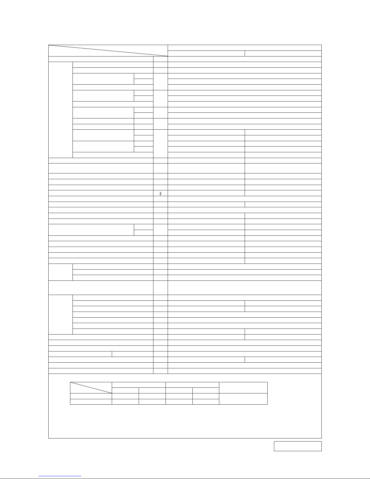
Model SRK25ZMP-S
Model
Item
SRK25ZMP-S
Indoor unit SRK25ZMP-S Outdoor unit SRC25ZMP-S
Power source 1 Phase, 220 - 240V, 50Hz
Operation
data
Nominal cooling capacity (range) kW 2.5 (0.9 (Min.) - 2.8 (Max.))
Nominal heating capacity (range) kW 2.8 (0.8 (Min.) - 3.9 (Max.))
Power
consumption
Cooling
kW
0.780 (0.25 - 1.01)
Heating 0.755 (0.20 - 1.43)
Max power consumption 1.65
Running
current
Cooling
A
3.9 / 3.8 / 3.6 (220 / 230 / 240 V)
Heating 3.8 / 3.7 / 3.5 (22 0 / 230 / 240 V)
Inrush current, max current 3.9 / 3.8 / 3.6 (220 / 230 / 240 V) Max. 9
Power factor
Cooling
%
90
Heating 89
EER Cooling 3.21
COP Heating 3.71
Sound power level
Cooling
dB(A)
59 60
Heating 58 59
Sound pressure level
Cooling Hi: 45 Me: 34 Lo: 23 47
Heating Hi: 43 Me: 34 Lo: 26 45
Silent mode sound pressure level — —
Exterior dimensions (Height x Width x Depth) mm 262 x 769 x 210 540 x 645(+57) x 275
Exterior appearance
(Munsell color)
Fine snow
(8.0Y 9.3/0.1) near equivalent
Stucco white
(4.2Y 7.5/1.1) near equivalent
Net weight kg 6.9 25
Compressor type & Q'ty — RM-B5077MDE5(Rotary type) x 1
Compressor motor (Starting method) kW — 0.75 (Inverter driven)
Refrigerant oil (amount, type) — 0.3 (DIAMOND FREEZE MA68)
Refrigerant (Type, amount, pre-charge length) kg R410A 0.655 in outdoor unit (incl. the amount for the piping of 10m)
Heat exchanger Louver fins & inner grooved tubing M fins & inner grooved tubing
Refrigerant control Capillary tubes + Electronic expansion valve
Fan type & Q'ty Tangential fan x 1 Propeller fan x 1
Fan motor (stating method) W 30 x1 (Direct drive) 24 x1 (Direct drive)
Air flow
Cooling
m3/min
Hi: 10.1 Me: 7.3 Lo: 4.2 26.0
Heating Hi: 9.5 Me: 7.3 Lo: 5.2 19.7
Available external static pressure Pa 0 0
Outside air intake Not possible —
Air filter, Quality / Quantity Polypropylene net (washable) —
Shock & vibration absorber Rubber sleeve (for fan motor) Rubber sleeve (for fan motor & compressor)
Electric heater — —
Operation
control
Remote control Wireless-Remote control
Room temperature control Microcomputer thermostat
Operation display RUN: Green, TIMER: Yellow
Safety equipments
Compressor overheat protection, Overcurrent protection,
Frost protection, Serial signal error protection, Indoor fan motor error protection,
Heating overload protection (High pressure control), Cooling overload protection
Installation
data
Refrigerant piping size (O.D) mm Liquid line :φ6.35 (1/4") Gas line :φ9.52 (3/8")
Connecting method Flare connection Flare connection
Attached length of piping m Liquid line : 0.39 / Gas line : 0.32 —
Insulation for piping Necessary (Both sides), independent
Refrigerant line (one way) length m Max. 15
Vertical height diff. between O.U. and I.U.
m Max. 10 (Outdoor unit is higher) / Max. 10 (Outdoor unit is lower)
Drain hose
Hose connectable (VP 16) Holes φ20 x 2 pcs
Drain pump, max lift height mm — —
Recommended breaker size A 16
L.R.A. (Locked rotor ampere) A 3.9 / 3.8 / 3.6 (220 / 230 / 240 V)
Interconnecting wires Size x Core number 1.5mm2 x 4 cores (Including earth cable) / Terminal block (Screw fixing type)
IP number IPX0 IPX4
Standard accessories Mounting kit
Option parts —
Note (1) The data are measured at the following conditions.
item
operation
Indoor air temperature Outdoor air temperature
Standards
DB WB DB WB
Cooling 27˚C 19˚C 35˚C 24˚C
ISO5151-T1
Heating 20˚C — 7˚C 6˚C
(2) This air-conditioner is manufactured and tested in conformity with the ISO.
(3) Sound level indicates the value in an anechoic chamber. During operation these value are somewhat
higher due to ambient conditions.
(4) Select the breaker size according to the own national standard.
(5) The refrigerant quantity to be charged includes the refrigerant in 10 m connecting piping.
(purging is not required even for the short piping. )
If the piping length is longer, when it is 10 to 15 m, add 20 g refrigerant per meter.
The pipe length is 7.5m.
1. SPECIFICATIONS
RWA000Z 2 4 9
-
4
-
'13 • SRK-T-140
RWA000Z 2 4 9
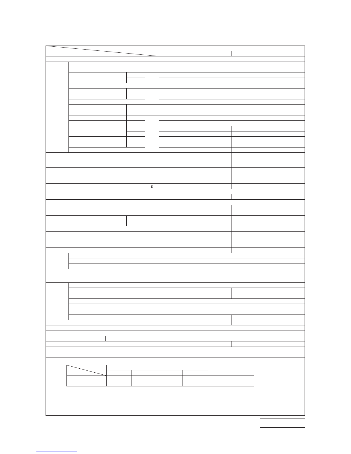
Model SRK35ZMP-S
Model
Item
SRK35ZMP-S
Indoor unit SRK35ZMP-S Outdoor unit SRC35ZMP-S
Power source 1 Phase, 220 - 240V, 50Hz
Operation
data
Nominal cooling capacity (range) kW 3.2 (0.9 (Min.) - 3.5 (Max.))
Nominal heating capacity (range) kW 3.6 (0.9 (Min.) - 4.3 (Max.))
Power
consumption
Cooling
kW
0.995 (0.23 - 1.32)
Heating 0.995 (0.19 - 1.31)
Max power consumption 1.65
Running
current
Cooling
A
4.9 / 4.7 / 4.5 (220 / 230 / 240 V)
Heating 4.9 / 4.7 / 4.5 (220 / 230 / 240 V)
Inrush current, max current 4.9 / 4.7 / 4.5 (220 / 230 / 240 V) Max. 9
Power factor
Cooling
%
93
Heating 93
EER Cooling 3.22
COP Heating 3.62
Sound power level
Cooling
dB(A)
60 60
Heating 58 60
Sound pressure level
Cooling Hi: 47 Me: 36 Lo: 23 49
Heating Hi: 44 Me: 36 Lo: 28 48
Silent mode sound pressure level — —
Exterior dimensions (Height x Width x Depth) mm 262 x 769 x 210 540 x 645(+57) x 275
Exterior appearance
(Munsell color)
Fine snow
(8.0Y 9.3/0.1) near equivalent
Stucco white
(4.2Y 7.5/1.1) near equivalent
Net weight kg 7.2 27
Compressor type & Q'ty — RM-B5077MDE5(Rotary type) x 1
Compressor motor (Starting method) kW — 0.90 (Inverter driven)
Refrigerant oil (amount, type) — 0.3 (DIAMOND FREEZE MA68)
Refrigerant (Type, amount, pre-charge length) kg R410A 0.81 in outdoor unit (incl. the amount for the piping of 15m)
Heat exchanger Louver fins & inner grooved tubing M fins & inner grooved tubing
Refrigerant control Capillary tubes + Electronic expansion valve
Fan type & Q'ty Tangential fan x 1 Propeller fan x 1
Fan motor (stating method) W 30 x1 (Direct drive) 24 x1 (Direct drive)
Air flow
Cooling
m3/min
Hi: 9.5 Me: 6.8 Lo: 4.2 25.4
Heating Hi: 9.6 Me: 7.4 Lo: 5.5 20.5
Available external static pressure Pa 0 0
Outside air intake Not possible —
Air filter, Quality / Quantity Polypropylene net (washable) —
Shock & vibration absorber Rubber sleeve (for fan motor) Rubber sleeve (for fan motor & compressor)
Electric heater — —
Operation
control
Remote control Wireless-Remote control
Room temperature control Microcomputer thermostat
Operation display RUN: Green, TIMER: Yellow
Safety equipments
Compressor overheat protection, Overcurrent protection,
Frost protection, Serial signal error protection, Indoor fan motor error protection,
Heating overload protection (High pressure control), Cooling overload protection
Installation
data
Refrigerant piping size (O.D) mm Liquid line :φ6.35 (1/4") Gas line :φ9.52 (3/8")
Connecting method Flare connection Flare connection
Attached length of piping m Liquid line : 0.39 / Gas line : 0.32 —
Insulation for piping Necessary (Both sides), independent
Refrigerant line (one way) length m Max. 15
Vertical height diff. between O.U. and I.U.
m Max. 10 (Outdoor unit is higher) / Max. 10 (Outdoor unit is lower)
Drain hose
Hose connectable (VP 16) Holes φ20 x 2 pcs
Drain pump, max lift height mm — —
Recommended breaker size A 16
L.R.A. (Locked rotor ampere) A 4.9 / 4.7 / 4.5 (220 / 230 / 240 V)
Interconnecting wires Size x Core number 1.5mm2 x 4 cores (Including earth cable) / Terminal block (Screw fixing type)
IP number IPX0 IPX4
Standard accessories Mounting kit
Option parts —
Note (1) The data are measured at the following conditions.
(2) This air-conditioner is manufactured and tested in conformity with the ISO.
(3) Sound level indicates the value in an anechoic chamber. During operation these value are somewhat higher
due to ambient conditions.
(4) Select the breaker size according to the own national standard.
(5) The refrigerant quantity to be charged includes the refrigerant in 15 m connecting piping.
(purging is not required even for the short piping. )
item
operation
Indoor air temperature Outdoor air temperature
Standards
DB WB DB WB
Cooling 27˚C 19˚C 35˚C 24˚C
ISO5151-T1
Heating 20˚C — 7˚C 6˚C
The pipe length is 7.5m.
-
5
-
'13 • SRK-T-140
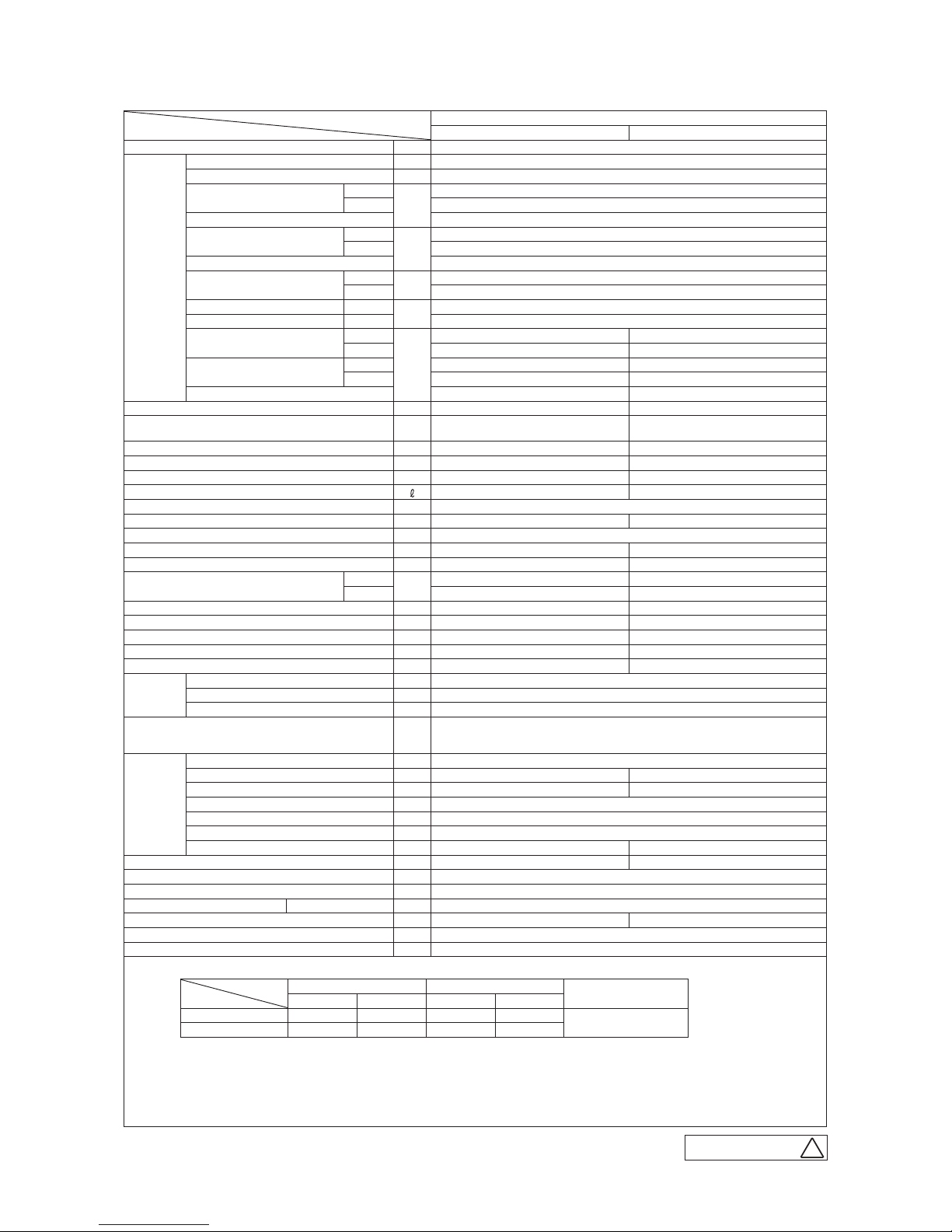
Model SRK45ZMP-S
Model
Item
SRK45ZMP-S
Indoor unit SRK45ZMP-S Outdoor unit SRC45ZMP-S
Power source 1 Phase, 220 - 240V, 50Hz
Operation
data
Nominal cooling capacity (range) kW 4.5 (0.9 (Min.) - 4.8 (Max.))
Nominal heating capacity (range) kW 5.0 (0.8 (Min.) - 5.8 (Max.))
Power
consumption
Cooling
kW
1.495 (0.22-1.98)
Heating 1.385 (0.20-1.86)
Max power consumption 2.68
Running
current
Cooling
A
7.0 / 6.7 / 6.4 (220 / 230 / 240 V)
Heating 6.5 / 6.2 / 6.0 (220 / 230 / 240 V)
Inrush current, max current 7.0 / 6.7 / 6.4 (220 / 230 / 240 V) Max.14
Power factor
Cooling
%
97
Heating 97
EER Cooling 3.01
COP Heating 3.61
Sound power level
Cooling
dB(A)
60 65
Heating 64 65
Sound pressure level
Cooling Hi : 46 Me : 40 Lo : 25 52
Heating Hi : 48 Me : 43 Lo : 32 53
Silent mode sound pressure level — —
Exterior dimensions (Height x Width x Depth) mm 262 x 769 x 210 595 x 780(+62) x 290
Exterior appearance
(Munsell color)
Fine snow
(8.0Y 9.3/0.1) near equivalent
Stucco white
(4.2Y 7.5/1.1) near equivalent
Net weight kg 7.6 40
Compressor type & Q'ty — GKT128MFA (Twin Potary type) x 1
Compressor motor (Starting method) kW — 1.10 (Inverter driven)
Refrigerant oil (amount, type) — 0.45 (FVC68D)
Refrigerant (Type, amount, pre-charge length) kg R410A 1.20 in outdoor unit (incl. the amount for the piping of 15m)
Heat exchanger Louver fins & inner grooved tubing M fins & inner grooved tubing
Refrigerant control Capillary tubes + Electronic expansion valve
Fan type & Q'ty Tangential fan x 1 Propeller fan x 1
Fan motor (stating method) W 30 x1 (Direct drive) 24 x1 (Direct drive)
Air flow
Cooling
m3/min
Hi : 9.0 Me : 7.2 Lo : 3.8 35.5
Heating Hi : 12.0 Me : 9.2 Lo : 6.2 33.5
Available external static pressure Pa 0 0
Outside air intake Not possible —
Air filter, Quality / Quantity Polypropylene net (washable) —
Shock & vibration absorber Rubber sleeve (for fan motor) Rubber sleeve (for fan motor & compressor)
Electric heater — —
Operation
control
Remote control Wireless-Remote control
Room temperature control Microcomputer thermostat
Operation display RUN: Green, TIMER: Yellow
Safety equipments
Compressor overheat protection, Overcurrent protection,
Frost protection, Serial signal error protection, Indoor fan motor error protection,
Heating overload protection (High pressure control), Cooling overload protection
Installation
data
Refrigerant piping size (O.D) mm Liquid line :φ6.35 (1/4") Gas line :φ12.7 (1/2")
Connecting method Flare connection Flare connection
Attached length of piping m Liquid line : 0.39 / Gas line : 0.32 —
Insulation for piping Necessary (Both sides), independent
Refrigerant line (one way) length m Max. 25
Vertical height diff. between O.U. and I.U.
m Max. 15 (Outdoor unit is higher) / Max. 15 (Outdoor unit is lower)
Drain hose
Hose connectable (VP 16) Holes φ20 x 2 pcs
Drain pump, max lift height mm — —
Recommended breaker size A 16
L.R.A. (Locked rotor ampere) A 7.0 / 6.7 / 6.4 (220 / 230 / 240 V)
Interconnecting wires Size x Core number 1.5mm2 x 4 cores (Including earth cable) / Terminal block (Screw fixing type)
IP number IPX0 IPX4
Standard accessories Mounting kit
Option parts —
(2) This air-conditioner is manufactured and tested in conformity with the ISO.
(3) Sound level indicates the value in an anechoic chamber. During operation these value are somewhat
higher due to ambient conditions.
(4) Select the breaker size according to the own national standard.
(5) The refrigerant quantity to be charged includes the refrigerant in 15 m connecting piping.
(purging is not required even for the short piping. )
If the piping length is longer, when it is 15 to 25 m, add 20 g refrigerant per meter.
Note (1) The data are measured at the following conditions.
item
operation
Indoor air temperature Outdoor air temperature
Standards
DB WB DB WB
Cooling 27˚C 19˚C 35˚C 24˚C
ISO5151-T1
Heating 20˚C — 7˚C 6˚C
The pipe length is 7.5m.
A
RWA000Z 2 4 9
-
6
-
'13 • SRK-T-140
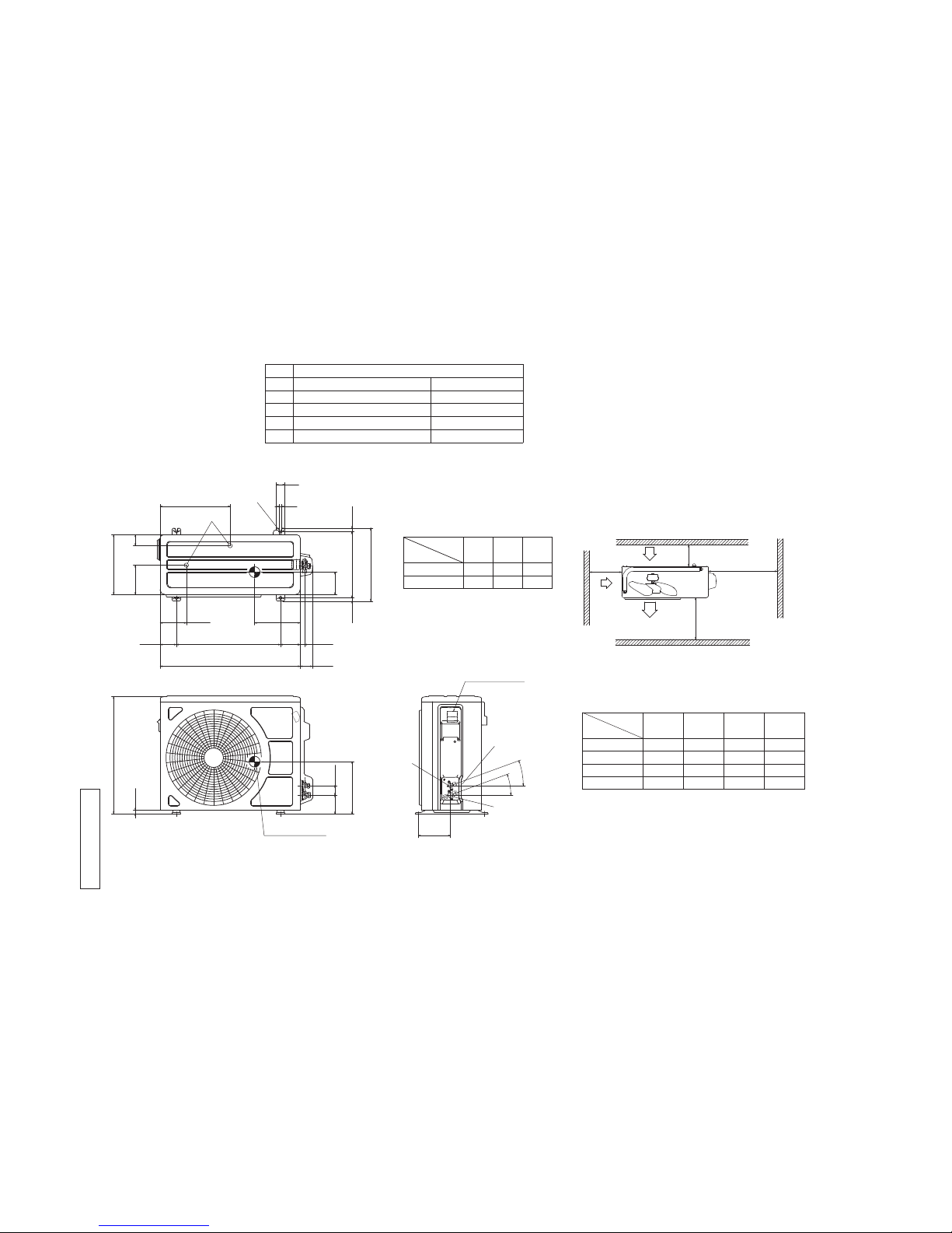
G
Terminal block
F
GG
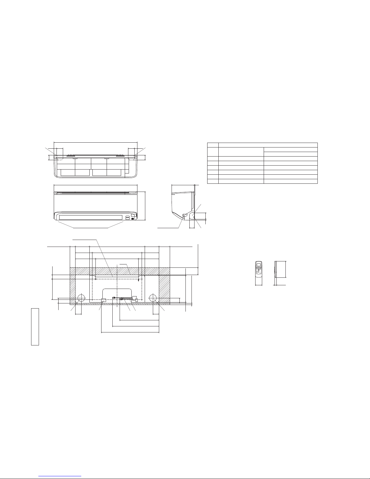
Unit:mm
Wireless remote control
Outlet for down piping
(Refer to the above view)
Space for installation and service when viewing from the front
D E C
Hole on wall for right rear piping
Hole on wall for left rear piping
Gas piping
Outlet for wiring
Drain hose
Liquid piping
F
E
C
D
B
Symbol
A
( φ65)
VP16
φ6.35(1/4")(Flare)
Content
( φ65)
Outlet for piping(on both side)
G
Model 25,35 φ9.52(3/8")(Flare)
Model 45 φ12.7(1/2")(Flare)
AB
Note(1)The model name label is attached
on the underside of the indoor unit.
60
150
17.3
190 40.1
47
130.5 508 130.5
157 455 157
187.5 394 187.5
47
7.6247.5
6.9
(Service space)
65
(Service space)
15
50
(Service space)
100
(Service space)
55
359.5
427.5
530
55
Installation plate
Unit
6025 60 25
768.1
45
45
769
262
45
609
210 3
RLC000Z003
2. EXTERIOR DIMENSIONS
(1) Indoor units
Models SRK25ZMP-S, 35ZMP-S, 45ZMP-S
-
7
-
'13 • SRK-T-140
( )
D
E
B
A
C
50
322
135
275
120.5
74.5 480 90.5 20.2
645 57.2
14.8
336
16.8
304.4
12
40
16.5
540
86.3
43.2
147.2
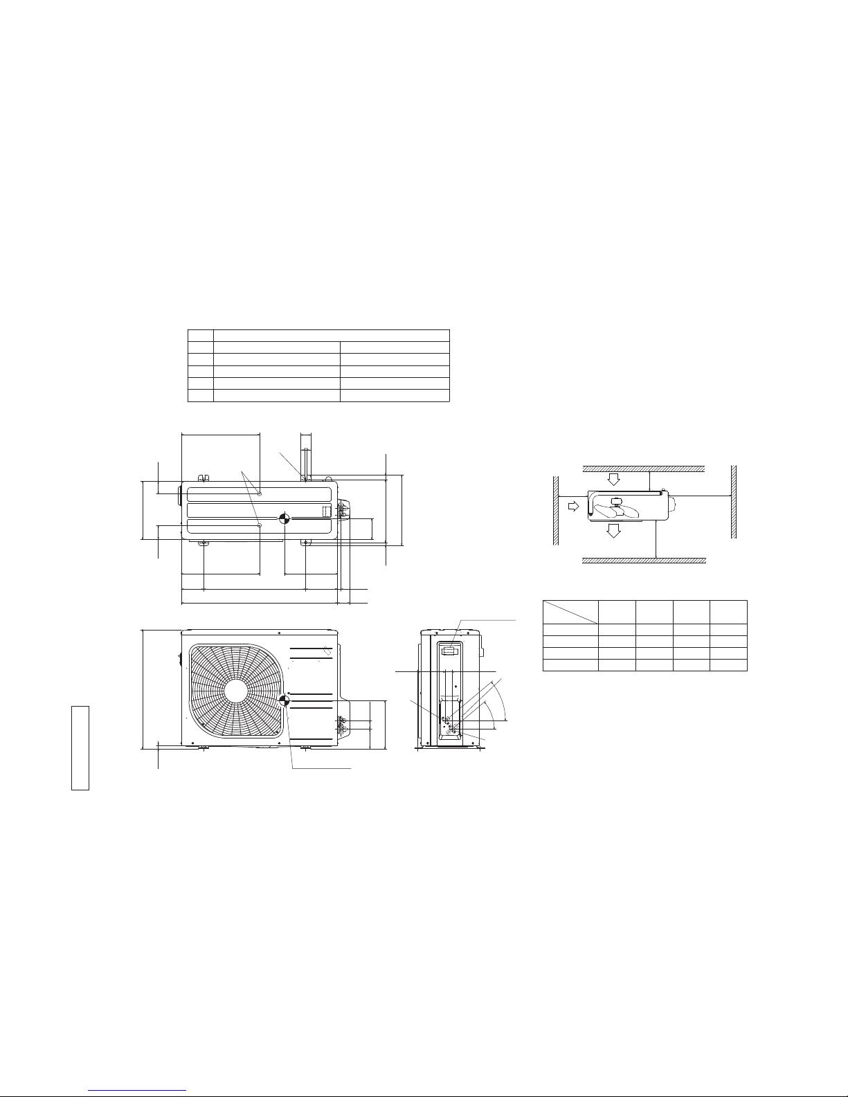
Center of gravity
※3
※1
※2
φ9.52(3/8")(Flare)
Content
C Pipe/cable draw-out hole
D
E Anchor bolt hole
Drain discharge hole
Symbol
B
A Service valve connection(gas side)
M10×4places
φ20×2places
Service valve connection(liquid side)
φ6.35(1/4")(Flare)
Unit:mm
L2
Intake
Outlet
Intake
L3
L1
Minimum installation space
Service
space
L4
L2
L3
L4
L1
100
100
250
Open
I Ⅱ Ⅲ Ⅳ
Open
250
80
280
280
Open
80
100
Examples of
Dimensions
installation
180
Open
80
Open
Terminal block
SRC35ZMP-S
SRC25ZMP-S
220
210
※1
108
103240
240
Dimensions
MODEL
※2 ※3
2
0
゜
2
0
゜
Notes
(1) It must not be surrounded by walls on the four sides.
(2) The unit must be fixed with anchor bolts. An anchor bolt must not
protrude more than 15mm.
(3) Where the unit is subject to strong winds, lay it in such
a direction that the blower outlet faces perpendicularly
to the dominant wind direction.
(4) Leave 1m or more space above the unit.
(5) A wall in front of the blower outlet must not exceed the units height.
(6) The model name label is attached on the right side of the unit.
RCW000Z002
(2) Outdoor units
Models SRC25ZMP-S, 35ZMP-S
-
8
-
'13 • SRK-T-140
( )
Center of gravity
L2
Intake
Outlet
Intake
L3
L1
Minimum installation space
Service
space
L4
L2
L3
L4
L1
100
100
250
Open
I Ⅱ
Open
250
80
280
Ⅲ
280
Open
80
100
Examples of
Dimensions
installation
Ⅳ
180
Open
80
Open
φ12.7(1/2")(Flare)
Content
CDPipe/cable draw-out hole
E Anchor bolt hole
Drain discharge hole
Symbol
B
A Service valve connection(gas side)
M10×4places
φ20×2places
Service valve connection(liquid side)
φ6.35(1/4")(Flare)
138.4 33.5
Terminal block
C
B
A
97.7 42.5
15.8
595
240
63.4
390.6
390.6
69.4
111.6 510 158.4
780 61.9
17.9
14.8 312.5 24.3
351.6
50.6
12
290
102
265
D
E
Unit:mm
Notes
(1) It must not be surrounded by walls on the four sides.
(2) The unit must be fixed with anchor bolts. An anchor bolt must not
protrude more than 15mm.
(3) Where the unit is subject to strong winds, lay it in such
a direction that the blower outlet faces perpendicularly
to the dominant wind direction.
(4) Leave 1m or more space above the unit.
(5) A wall in front of the blower outlet must not exceed the units height.
(6) The model name label is attached on the lower right corner of the front panel.
4
0
゜
4
0
゜
RCV000Z016
Model SRC45ZMP-S
-
9
-
'13 • SRK-T-140
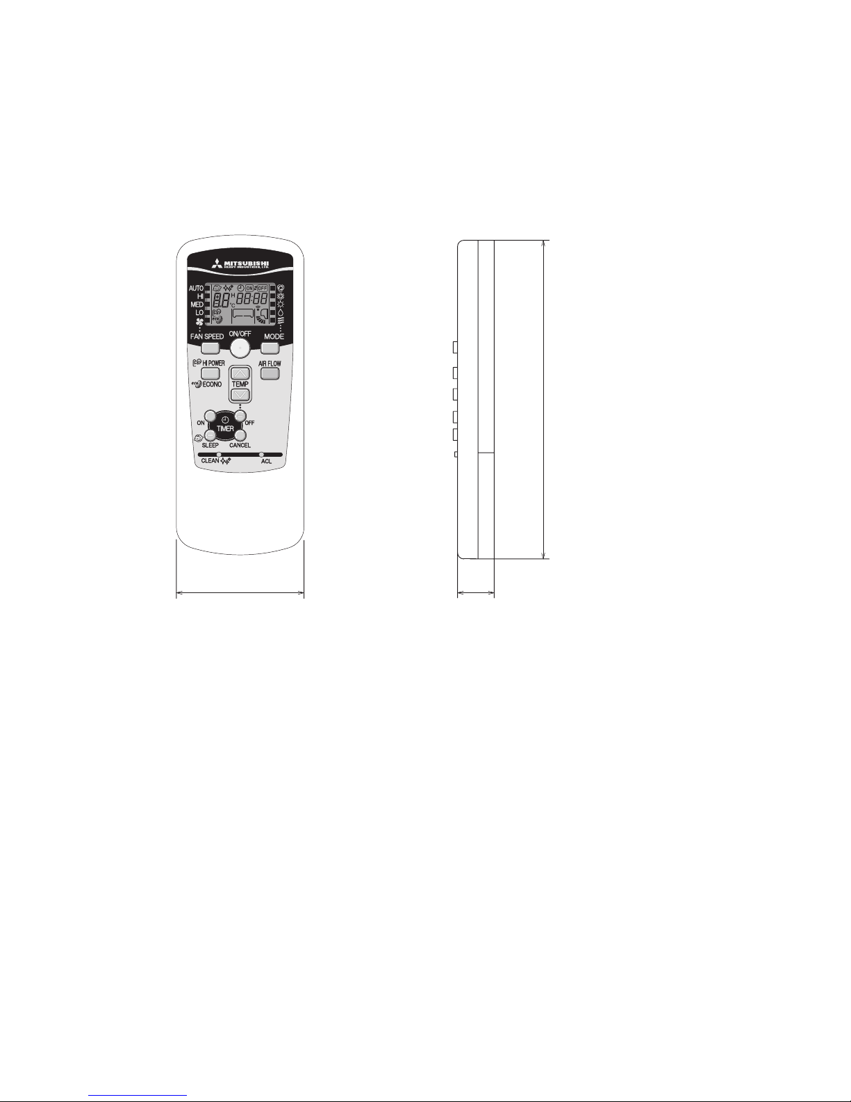
Unit: mm
60
17.3
150
(3) Wireless remote control
-
10
-
'13 • SRK-T-140
G
J
WIRELESS
R-AMP
DISPLAY
S/N
CNGCNE
250V 3.15A
CNU
CNM
BACK UP SW
5
U
M
M
CNF
F M
S M
F
Va
DS
L
Blue
BlackBK
Red
BL
RD
WhiteWH
Yellow/GreenY/G
ColorMark
Heat exch. sensor
Fan motor
Room temp. sensor
Flap motor
Diode stackDS
FuseF
ConnectorCNE
FM
Terminal blockTB
Description
Item
VaristorVa
SM
Th
I
Th
2
YellowY
Humidity sensor
HD
CNF
CNG
CNM
CNU
BK
Y/G
RD
Y
WH
Y/G
RD
BK
BOX,
CONTROL
3
2/N
WH
6
TO OUTDOOR UNIT
1
1 3 4 5
RDBKBL
HEAT
EXCHANGER
WH
6 2 2 2
ThITh
2
TB
t゜
t゜
HD
HEAT
EXCHANGER
PWB ASSY
RW A 0 00Z25 0
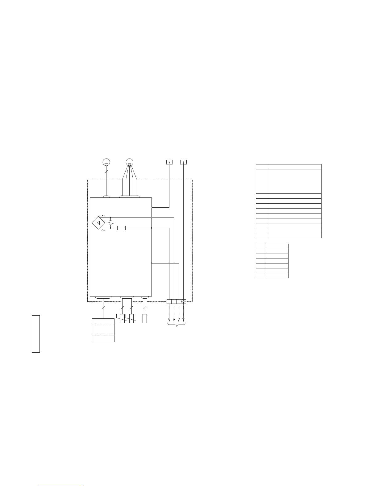
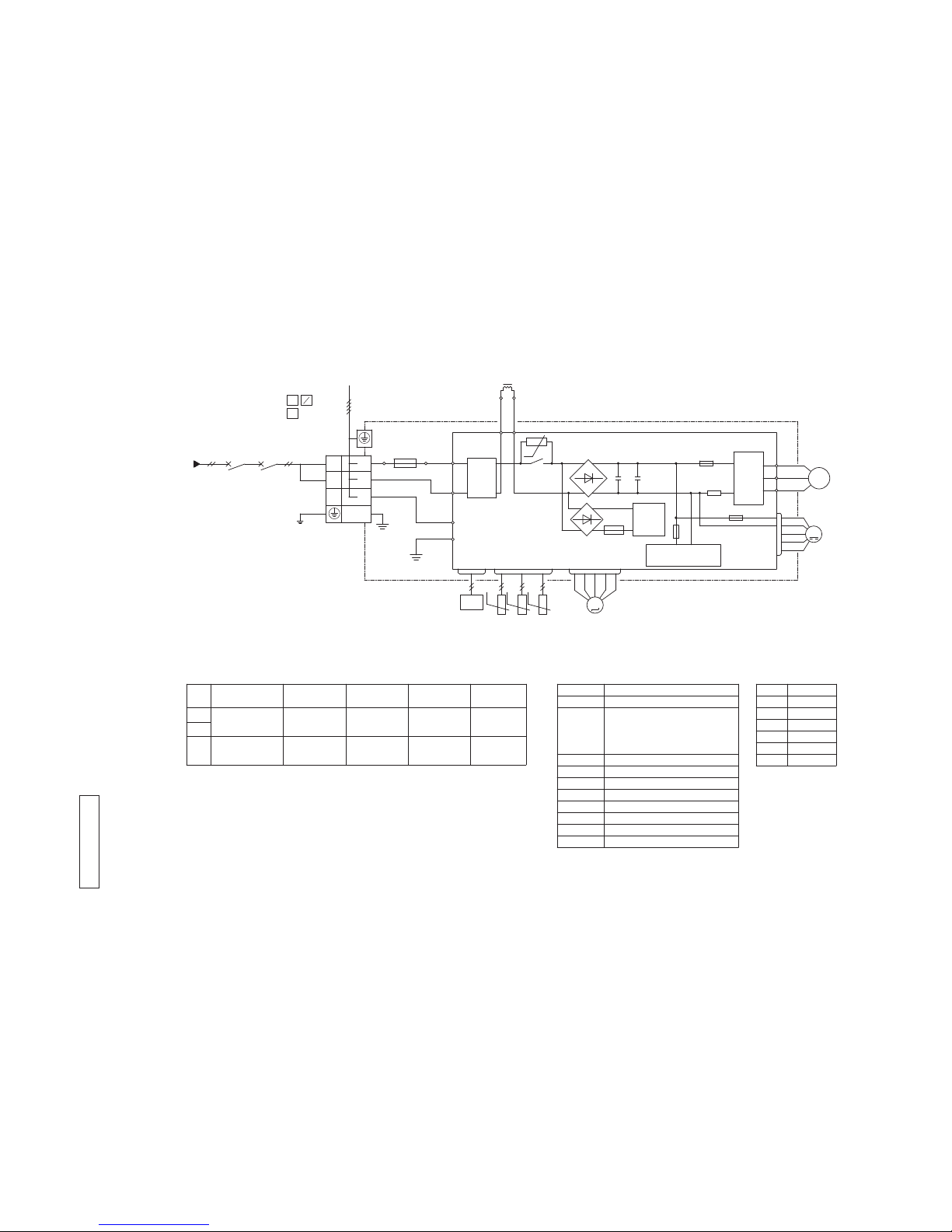
3. ELECTRICAL WIRING
(1) Indoor units
Models SRK25ZMP-S, 35ZMP-S, 45ZMP-S
-
11
-
'13 • SRK-T-140
[ ]
Color
RD
Mark
OrangeOR
Yellow/GreenY/G
BlackBK
YellowY
WhiteWH
Red
DescriptionItem
Connector
Electric expansion valve(coil)
EEV
Fan motor
FMo
Reactor
L
Terminal block
TB
Compressor motor
CM
Solenoid coil for 4 way valve
20S
Heat exchanger sensor(outdoor unit)
TH1
Outdoor air temp. sensor
TH2
TH3
Discharge pipe temp. sensor
CN20S
CNEEV
CNFAN
CNTH
25
Model
Power cable, indoor-outdoor connecting wires
●
The specifications shown in the above table are for units without heaters. For units with heaters, refer
to the installation instructions or the construction instructions of the indoor unit.
●
Switchgear of Circuit breaker capacity which is calculated from MAX. over current should be chosen
along the regulations in each country.
●
The cable specifications are based on the assumption that a metal or plastic conduit is used with no
more than three cables contained in a conduit and a voltage drop is 2%. For an installation falling
outside of these conditions, please follow the internal cabling regulations. Adapt it to the regulation
in effect in each country.
35
9 2.0 32
1.5mm2x 4 1.5
3
1
2
N
~220-240V 50Hz
POWER SOURCE
45 14 2.0 18
1.5mm2x 4 1.5
(BK)
C-2
G1
(RD)
(Y/G)
S.IN(WH)
R.IN
(BK)
(WH)
(RD)
PWB ASSY
250V 20A
F2
F3 250V 1A
++
F4
250V 10A
F1
250V 2A
CIRCUIT
PAM
SWITCHING POWER
CIRCUIT
P
W
V
U
TRANSISTOR
POWER
W
V
U
FILTER
NOISE
CN20S
CNTH
CNEEV
CNFAN
M
M
3~
250V 15A
(Y/G)
T1
T2
(OR)
(Y)
M
TH1 TH2 TH3
EEV
FMo
CM
t゜
LN1
3
2
TB
TO INDOOR UNIT
POWER WIRES
SIGNAL WIRE
20S
L
N
t゜t゜t゜
MAX running current
Power cable size
(mm2)
(A)
Power cable length
(m)
indoor-outdoor
wire size x number
Earth wire size
(mm2)
RW C 0 00Z26 1
(2) Outdoor units
Models SRC25ZMP-S, 35ZMP-S, 45ZMP-S
-
12
-
'13 • SRK-T-140
10
20
30
40
50
60
70
63 125 250 500 1000 2000 4000 8000
Mid Octave Band frequency(Hz)
10
20
30
40
50
60
70
N50
N30
N40
N60
N70
N20
Sound Pressure Level (dB)
(Standard 2 10
-5
Pa)
10
20
30
40
50
60
70
63 125 250 500 1000 2000 4000 8000
Mid Octave Band frequency(Hz)
10
20
30
40
50
60
70
N50
N30
N40
N60
N70
N20
Sound Pressure Level (dB)
(Standard 2 10
-5
Pa)
10
20
30
40
50
60
70
63 125 250 500 1000 2000 4000 8000
Mid Octave Band Frequency(Hz)
10
20
30
40
50
60
70
N50
N30
N40
N60
N70
N20
Sound Pressure Level (dB)
(Standard 2 10
-5
Pa)
(Outdoor Unit)
Model SRC25ZMP-S
Noise
Level
Cooling 47 dB(A)
Heating 45 dB(A)
(Indoor Unit)
Model SRK25ZMP-S
Noise
Level
Cooling 45 dB(A)
Heating 43 dB(A)
×
......
Cooling Heating
×
......
Cooling Heating
Condition ISO-T1,JIS C 9612
●
Mike position
0.8m
1m
Unit
Mike position
(Center & Low points)
4. NOISE LEVEL
Model SRK25ZMP-S
●
Mike position: at highest noise level in position as mentioned below
Distance from front side 1m
-
13
-
'13 • SRK-T-140
10
20
30
40
50
60
70
63 125 250 500 1000 2000 4000 8000
Mid Octave Band Frequency(Hz)
10
20
30
40
50
60
70
N50
N30
N40
N60
N70
N20
Sound Pressure Level (dB)
(Standard 2 10
-5
Pa)
(Outdoor Unit)
Model SRC35ZMP-S
Noise
Level
Cooling 49 dB(A)
Heating 48 dB(A)
×
......
Cooling Heating
(Indoor Unit)
Model SRK35ZMP-S
Noise
Level
Cooling 47 dB(A)
Heating 44 dB(A)
×
......
Cooling Heating
Condition ISO-T1,JIS C 9612
●
Mike position
0.8m
1m
Unit
Mike position
(Center & Low points)
Model SRK35ZMP-S
10
20
30
40
50
60
70
63 125 250 500 1000 2000 4000 8000
Mid Octave Band Frequency(Hz)
10
20
30
40
50
60
70
N50
N30
N40
N60
N70
N20
Sound Pressure Level (dB)
(Standard 2 10
-5
Pa)
10
20
30
40
50
60
70
63 125 250 500 1000 2000 4000 8000
Mid Octave Band Frequency(Hz)
10
20
30
40
50
60
70
N50
N30
N40
N60
N70
N20
Sound Pressure Level (dB)
(Standard 2 10
-5
Pa)
●
Mike position: at highest noise level in position as mentioned below
Distance from front side 1m
-
14
-
'13 • SRK-T-140
10
20
30
40
50
60
70
63 125 250 500 1000 2000 4000 8000
Mid Octave Band Frequency(Hz)
10
20
30
40
50
60
70
N50
N30
N40
N60
N70
N20
Sound Pressure Level (dB)
(Standard 2 10
-5
Pa)
10
20
30
40
50
60
70
63 125 250 500 1000 2000 4000 8000
Mid Octave Band Frequency(Hz)
10
20
30
40
50
60
70
N50
N30
N40
N60
N70
N20
Sound Pressure Level (dB)
(Standard 2 10
-5
Pa)
10
20
30
40
50
60
70
63 125 250 500 1000 2000 4000 8000
Mid Octave Band Frequency(Hz)
10
20
30
40
50
60
70
N50
N30
N40
N60
N70
N20
Sound Pressure Level (dB)
(Standard 2 10
-5
Pa)
(Indoor Unit)
Model SRK45ZMP-S
Noise
Level
Cooling 46 dB(A)
Heating 48 dB(A)
×
......
Cooling Heating
Condition ISO-T1,JIS C 9612
●
Mike position
0.8m
1m
Unit
Mike position
(Center & Low points)
(Outdoor Unit)
Model SRC45ZMP-S
Noise
Level
Cooling 52 dB(A)
Heating 53 dB(A)
×
......
Cooling Heating
Model SRK45ZMP-S
●
Mike position: at highest noise level in position as mentioned below
Distance from front side 1m
-
15
-
'13 • SRK-T-140
'09•SRK-DB-087D
5 PIPING SYSTEM
Models SRK20ZJ-S, 25ZJ-S
Accumulator
Model SRK35ZJ-S
Accumulator
HD
Humidity
sensor
HD
Humidity
sensor
12.7
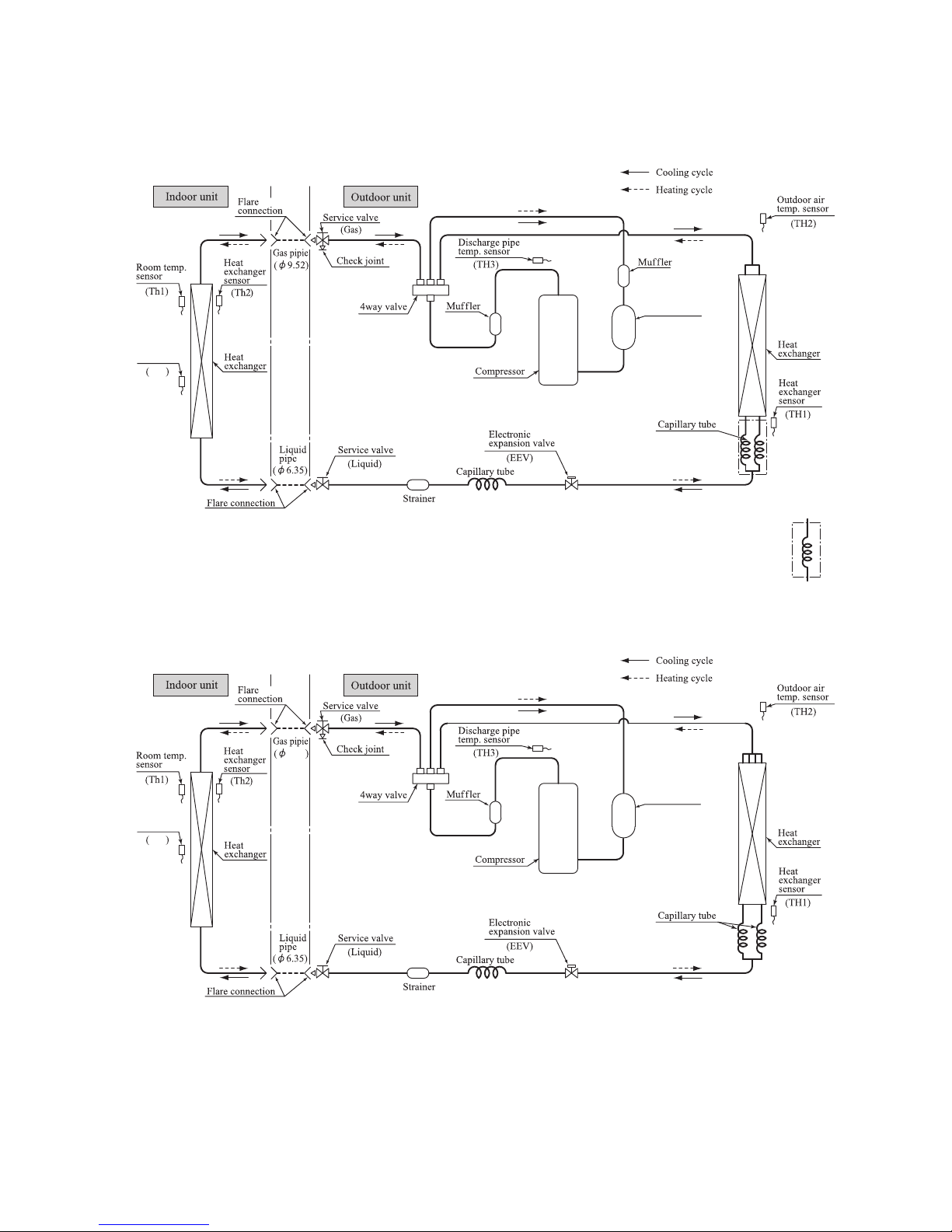
Case of
SRK35ZMP-S
Case of
SRK25ZMP-S
5. PIPING SYSTEM
Models SRK25ZMP-S, 35ZMP-S
Model SRK45ZMP-S
-
16
-
'13 • SRK-T-140
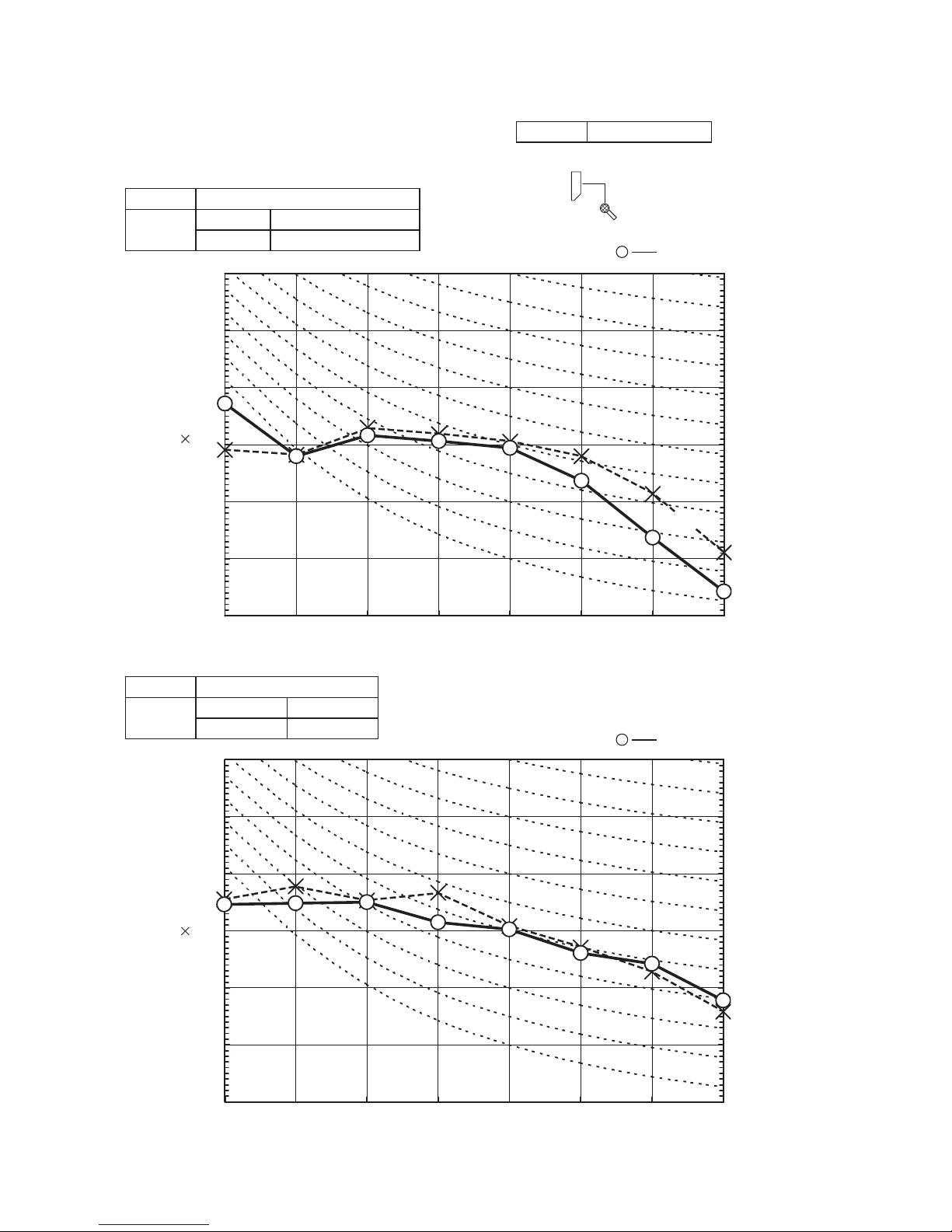
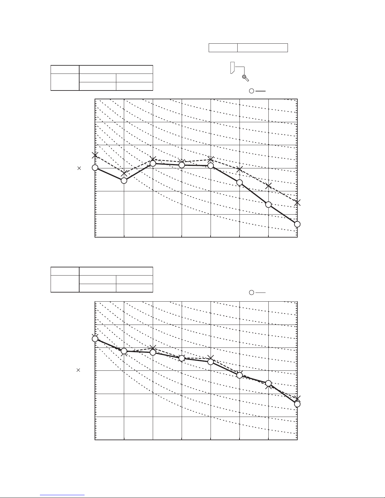
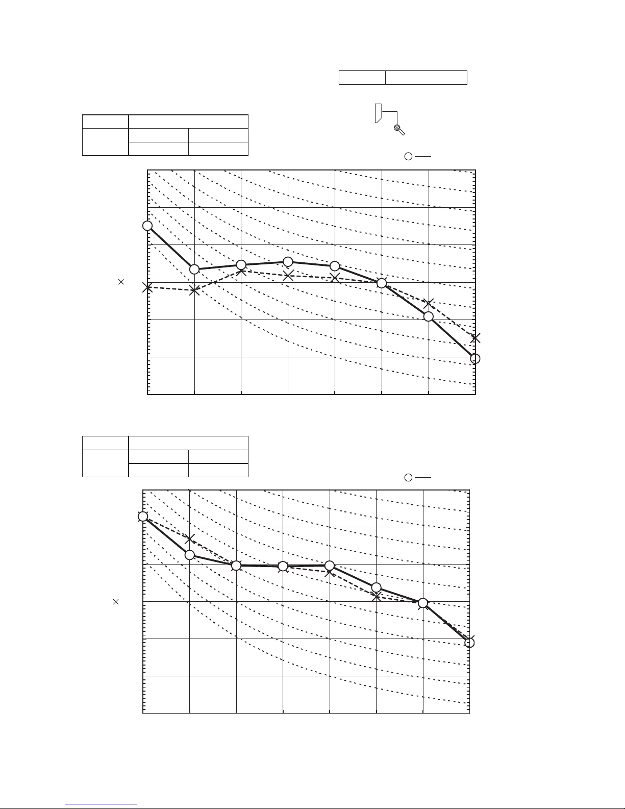
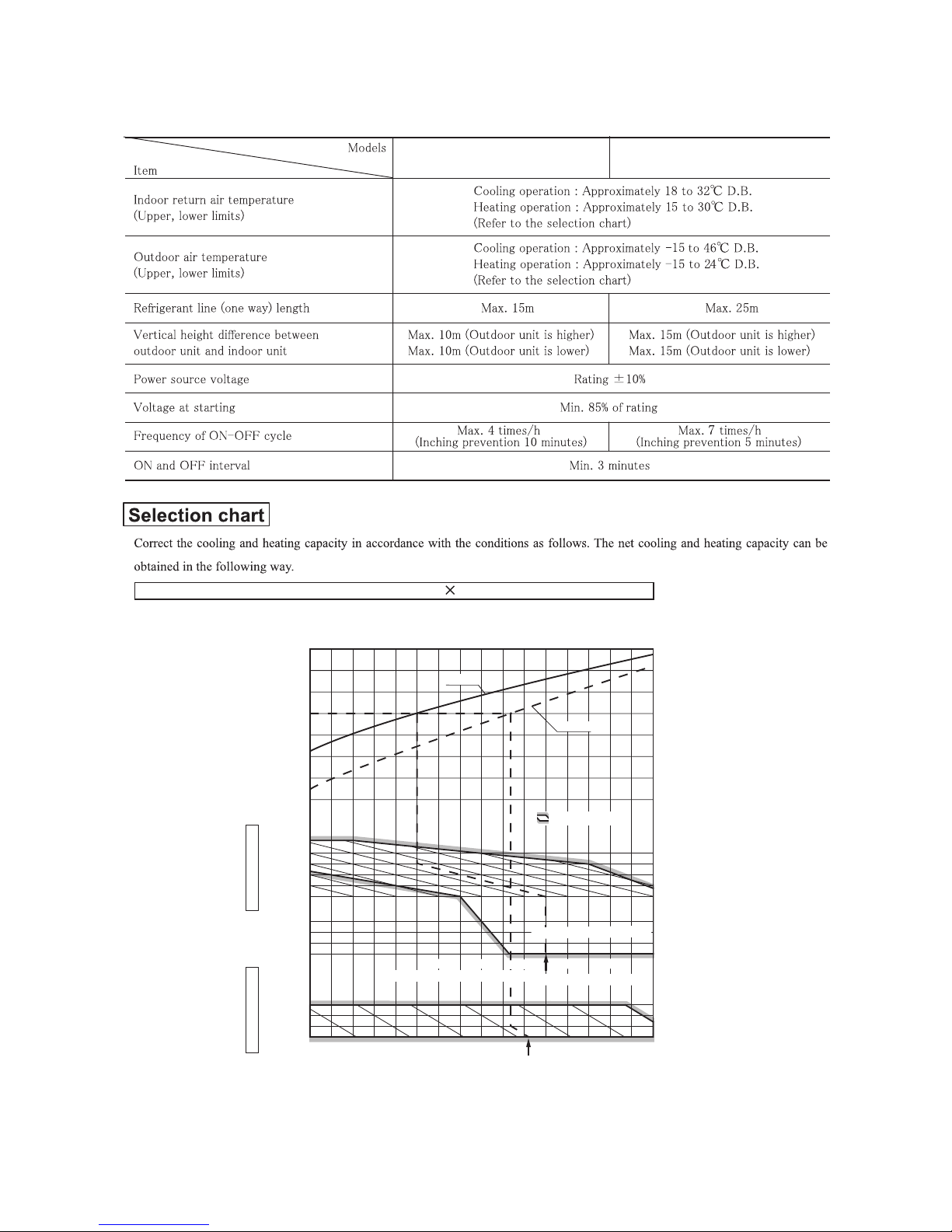
6. RANGE OF USAGE & LIMITATIONS
SRK25ZMP-S, 35ZMP-S SRK45ZMP-S
Net capacity = Capacity shown on specification Correction factors as follows.
(1) Coefficient of cooling and heating capacity in relation to temperatures
0.6
0.7
0.8
0.9
1.0
1.2
1.1
1.3
0
-5
-10
-15
24
26
20
25
30
35
40
46
15
20
25
30
Outdoor air W.B. temperature °C W.B.
-10 -5 0 5 10 15
.
Cooling operation
Outdoor air D.B.
temperature
°C D. B.
Coefficient of cooling
&
Heating capacity in
relation to temperature
Heating operation
Indoor air D.B.
temperature
°C D. B.
ISO-T1 Standard Condition
Depends on installed situation
ISO-T1 Standard Condition
2220181614
Indoor air W.B. temperature °C W.B
Applicable range
Cooling
Heating
-
17
-
'13 • SRK-T-140
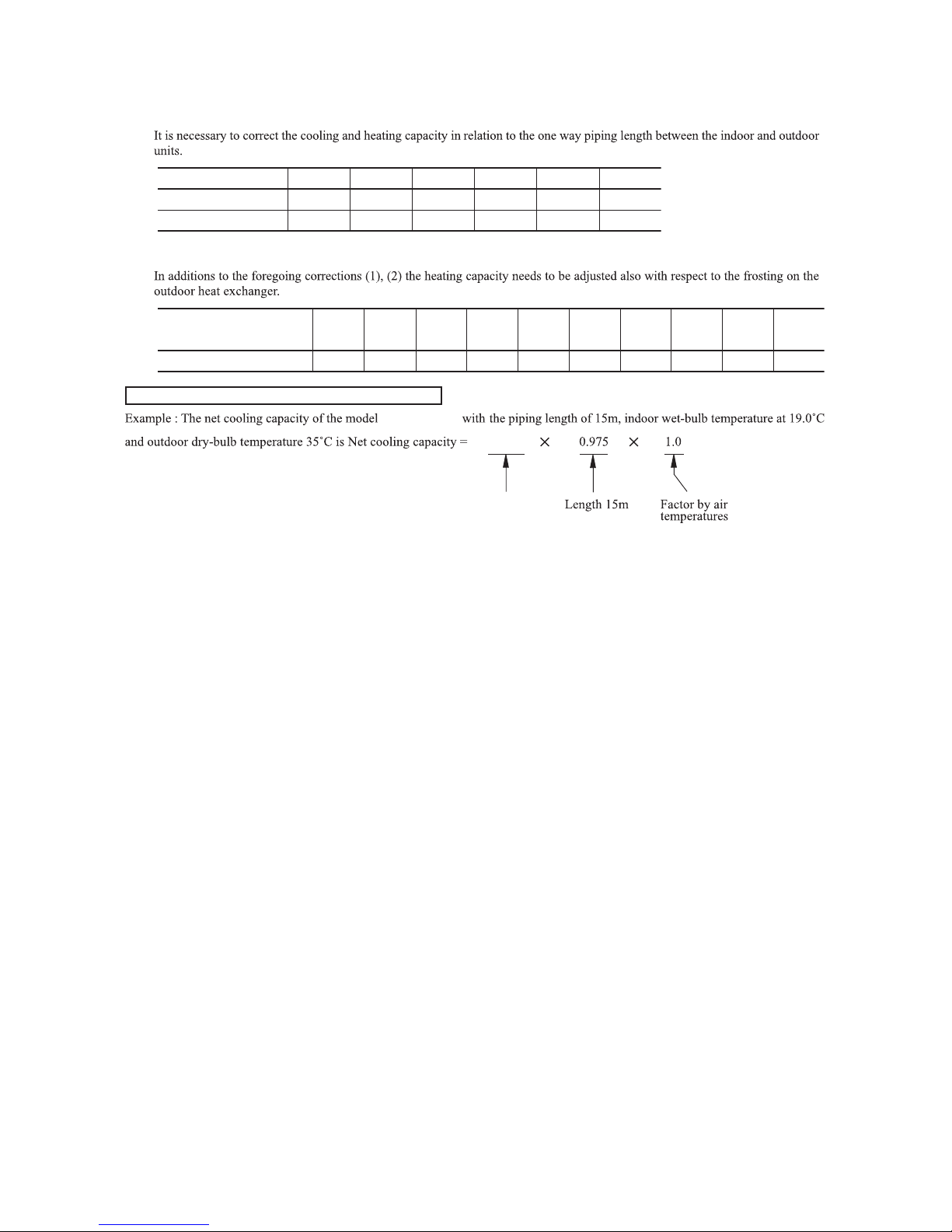
(2) Correction of cooling and heating capacity in relation to one way length of refrigerant piping
(3) Correction relative to frosting on outdoor heat exchanger during heating
How to obtain the cooling and heating capacity
≒
Piping length [m]
Cooling
Heating
7
1.0
1.0
10
0.99
1.0
15
0.975
1.0
20
0.965
1.0
25
0.95
1.0
30
0.935
1.0
Air inlet temperature of
SRK35ZMP-S
SRK35ZMP-S
outdoor unit in °C WB
Adjustment coefficient
-15
0.95 0.95 0.94 0.93 0.91 0.88 0.86 0.87 0.92 1.00
-10 -9 -7 -5 -3 -1 1 3
5 or more
3.2 3.1kW
-
18
-
'13 • SRK-T-140
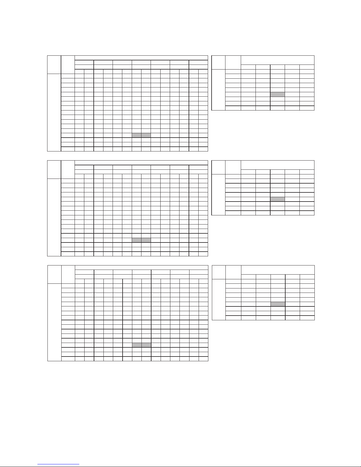
7. CAPACITY TABLES
Note(1) These data show average statuses.
Note(1) Depending on the system control, there may be ranges where the operation
is not conducted continuously.
Note(1)
These data show the case where the operation frequency of a compressor is
fixed.
(2) Capacities are based on the following conditions.
(2) Corresponding refrigerant piping length :7m
(2) Level difference of Zero.
(3) Symbols are as follows.
TC : Total cooling capacity (kW)
SHC : Sensible heat capacity (kW)
HC : Heating capacity (kW)
Heating Mode(HC)
Air flow Outdoor 21˚CDB 23˚C DB 26 ˚CDB 27˚C DB 28˚C DB 31˚CDB
Outdoor
air temp.
14˚C WB 16˚CWB 18˚CWB 19˚CWB 20˚CWB 22˚CWB
33˚CDB
24˚CWB
Air flow air temp. Indoor air temp
61
CHSCTCHSCTCHSCTCHSCTCHSCTCHSCTCHSCT
18˚CDB 20˚CDB 22˚CDB 24˚CDB
10 2.82 2.36 2.95 2.32 3.06 2.42 3.11 2.39 3.16 2.36 3.26 2.46 3.34 2.39
˚CWB 1.72 1.69 1.65 1.61 1.58
12 2.77 2.34 2.90 2.30 3.01 2.40 3.07 2.37 3.12 2.35 3.22 2.45 3.31 2.38
˚CWB 1.95 1.91 1.89 1.84 1.80
14 2.71 2.31 2.85 2.27 2.97 2.39 3.03 2.36 3.08 2.33 3.18 2.43 3.28 2.37
˚CWB 2.11 2.08 2.04 2.02 1.98
16 2.66 2.28 2.80 2.25 2.92 2.37 2.98 2.35 3.04 2.32 3.15 2.42 3.24 2.36
˚CWB 2.21 2.18 2.14 2.12 2.09
18 2.60 2.26 2.74 2.23 2.88 2.35 2.94 2.33 2.99 2.31 3.11 2.41 3.20 2.35
˚CWB 2.82 2.79 2.77 2.72 2.68
20 2.55 2.23 2.68 2.21 2.83 2.33 2.89 2.31 2.95 2.29 3.07 2.39 3.17 2.34
(
m
3
/
min
)
˚C
Hi 22 2.49 2.20 2.63 2.18 2.78 2.31 2.84 2.29 2.90 2.27 3.02 2.38 3.13 2.32
˚CWB 3.04 3.02 3.00 2.96 2.93
10.1 24 2.43 2.18 2.57 2.15 2.72 2.29 2.80 2.27 2.85 2.25 2.98 2.36 3.08 2.31
˚CWB 3.31 3.28 3.26 3.23 3.20
(
m3/min
)
26 2.37 2.14 2.51 2.13 2.67 2.27 2.74 2.25 2.80 2.23 2.93 2.35 3.04 2.29
˚CWB 3.56 3.53 3.52 3.48 3.45
28 2.31 2.12 2.44 2.10 2.61 2.24 2.69 2.23 2.75 2.21 2.89 2.33 3.00 2.28
30 2.24 2.09 2.38 2.07 2.56 2.22 2.64 2.21 2.70 2.19 2.84 2.31 2.95 2.27
32 2.18 2.06 2.31 2.04 2.50 2.20 2.58 2.19 2.64 2.17 2.79 2.30 2.90 2.25
34 2.11 2.03 2.25 2.01 2.44 2.18 2.53 2.17 2.59 2.15 2.74 2.28 2.85 2.24
36 2.04 1.99 2.18 1.98 2.38 2.15 2.47 2.14 2.53 2.13 2.69 2.26 2.80 2.22
38 1.97 1.97 2.11 1.95 2.32 2.12 2.41 2.12 2.47 2.11 2.63 2.24 2.75 2.20
39 1.94 1.94 2.07 1.94 2.28 2.11 2.38 2.11 2.44 2.10 2.61 2.23 2.72 2.20
Heating Mode(HC)
Outdoor
Air flow air temp. Indoor air temp
61
CHSCTCHSCTCHSCTCHSCTCHSCTCHSCTCHSCT
˚CDB
10 3.61 2.75 3.77 2.70 3.91 2.80 3.98 2.76 4.05 2.72 4.17 2.79 4.28 2.70
˚CWB 2.21 2.17 2.12 2.07 2.03
12 3.54 2.72 3.71 2.67 3.86 2.77 3.93 2.73 4.00 2.70 4.12 2.77 4.24 2.68
˚CWB 2.51 2.46 2.43 2.37 2.32
14 3.47 2.69 3.65 2.64 3.80 2.74 3.87 2.71 3.94 2.67 4.08 2.75 4.19 2.67
˚CWB 2.71 2.68 2.62 2.59 2.55
16 3.40 2.65 3.58 2.61 3.74 2.72 3.82 2.68 3.89 2.64 4.03 2.74 4.15 2.65
˚CWB 2.85 2.80 2.76 2.72 2.68
18 3.33 2.61 3.51 2.57 3.68 2.68 3.76 2.66 3.83 2.62 3.98 2.71 4.10 2.64
˚CWB 3.63 3.58 3.56 3.49 3.44
20 3.26 2.58 3.44 2.54 3.62 2.66 3.70 2.63 3.78 2.60 3.92 2.69 4.05 2.61
(
m
3
/
min
)
˚C
Hi 22 3.19 2.54 3.36 2.51 3.55 2.63 3.64 2.61 3.71 2.58 3.87 2.68 4.00 2.59
˚CWB 3.91 3.88 3.85 3.80 3.76
9.5 24 3.11 2.50 3.29 2.47 3.49 2.60 3.58 2.58 3.65 2.56 3.81 2.64 3.95 2.58
˚CWB 4.26 4.22 4.19 4.15 4.11
(
m3/min
)
26 3.03 2.46 3.21 2.43 3.42 2.57 3.51 2.55 3.59 2.53 3.76 2.62 3.89 2.56
˚CWB 4.58 4.54 4.52 4.47 4.43
28 2.95 2.42 3.13 2.39 3.35 2.54 3.45 2.53 3.52 2.50 3.70 2.61 3.84 2.55
30 2.87 2.38 3.05 2.35 3.27 2.51 3.38 2.50 3.45 2.47 3.64 2.59 3.78 2.52
32 2.79 2.34 2.96 2.32 3.20 2.48 3.31 2.47 3.38 2.45 3.57 2.56 3.72 2.51
34 2.70 2.30 2.88 2.28 3.12 2.45 3.24 2.44 3.31 2.42 3.51 2.54 3.65 2.48
36 2.61 2.25 2.79 2.24 3.04 2.41 3.16 2.41 3.24 2.39 3.44 2.51 3.59 2.46
38 2.52 2.21 2.70 2.20 2.96 2.38 3.09 2.38 3.16 2.36 3.37 2.49 3.52 2.44
39 2.48 2.19 2.65 2.18 2.92 2.36 3.05 2.36 3.12 2.34 3.34 2.48 3.49 2.43
Indoor air temp
Indoor air temp
35 2.66 2.27 2.83 2.26 3.08 2.43 3.20 2.43 3.28 2.40 3.47 2.52 3.62 2.47
WB 3.68 3.64 3.60 3.55 3.51
35 2.08 2.01 2.21 2.00 2.41 2.16 2.50 2.16 2.56 2.14 2.71 2.27 2.83 2.23
WB 2.87 2.83 2.80 2.76 2.73
(kW)
(kW)
(kW)
(kW)
(kW)
(kW)
-15
-10
-5
Hi 0
9.5 5
10
15
20
15
-10
-5
Hi 0
9.6 5
6
10
15
20
˚CDB 23˚C DB 26˚C DB 27 ˚CDB 28˚CDB 31˚CDB
˚CWB 16˚CWB 18˚CWB 19˚CWB 20˚CWB 22˚CWB
33˚CDB
24˚CWB
˚CDB
18˚CDB 20˚CDB 22˚CDB 24˚CDB
6
Heating Mode(HC)
Air flow Outdoor 21 ℃DB 23 ℃DB 26 ℃DB 27 ℃DB 28 ℃DB 31 ℃DB 33 ℃DB
Outdoor
air temp. 14 ℃WB 16 ℃WB 18 ℃WB 19 ℃WB 20 ℃WB 22 ℃WB 24 ℃WB
Air flow air temp. Indoor air temp
61
CHSCTCHSCTCHSCTCHSCTCHSCTCHSCTCHSCT
℃ DB 18℃ DB 20℃ DB 22℃ DB 24℃ DB
10 5.07 3.57 5.31 3.52 5.50 3.58 5.59 3.53 5.69 3.47 5.86 3.50 6.02 3.36
℃WB 3.08 3.01 2.94 2.88 2.81
12 4.98 3.52 5.22 3.47 5.42 3.54 5.52 3.49 5.62 3.43 5.80 3.47 5.96 3.34
℃WB 3.48 3.42 3.37 3.29 3.22
14 4.88 3.47 5.13 3.42 5.34 3.50 5.45 3.45 5.55 3.40 5.73 3.43 5.90 3.31
℃WB 3.77 3.72 3.64 3.60 3.54
16 4.79 3.41 5.03 3.37 5.26 3.45 5.37 3.41 5.47 3.36 5.66 3.41 5.83 3.29
℃WB 3.95 3.89 3.83 3.78 3.73
18 4.69 3.35 4.93 3.31 5.18 3.41 5.29 3.37 5.39 3.32 5.59 3.38 5.77 3.26
℃WB 5.04 4.98 4.95 4.85 4.78
20 4.59 3.30 4.83 3.26 5.09 3.36 5.20 3.32 5.31 3.28 5.52 3.34 5.70 3.23
(
m
3
/
min
)
6
℃WB 5.12 5.06 5.00 4.94 4.88
Hi 22 4.48 3.23 4.73 3.20 5.00 3.31 5.12 3.28 5.22 3.24 5.44 3.31 5.63 3.20
℃WB 5.44 5.38 5.35 5.28 5.23
9.0 24 4.37 3.18 4.62 3.14 4.90 3.27 5.03 3.24 5.14 3.20 5.36 3.27 5.55 3.17
12.0
℃WB 5.92 5.87 5.82 5.76 5.71
(
m3/min
)
26 4.26 3.11 4.51 3.08 4.80 3.22 4.94 3.20 5.05 3.16 5.28 3.24 5.48 3.14
℃WB 6.36 6.31 6.28 6.21 6.16
28 4.15 3.05 4.40 3.02 4.70 3.17 4.85 3.15 4.95 3.12 5.20 3.20 5.40 3.10
30 4.04 2.98 4.28 2.96 4.60 3.12 4.75 3.11 4.86 3.07 5.11 3.16 5.31 3.08
32 3.92 2.92 4.16 2.90 4.50 3.06 4.65 3.06 4.76 3.02 5.02 3.13 5.23 3.04
34 3.80 2.85 4.04 2.84 4.39 3.02 4.55 3.01 4.66 2.98 4.93 3.09 5.14 3.01
36 3.67 2.79 3.92 2.78 4.28 2.96 4.45 2.96 4.55 2.93 4.84 3.05 5.05 2.98
38 3.55 2.72 3.79 2.71 4.17 2.91 4.34 2.92 4.45 2.89 4.74 3.01 4.95 2.94
39 3.48 2.69 3.73 2.68 4.11 2.88 4.29 2.89 4.39 2.86 4.69 2.99 4.90 2.92
Indoor air temp
35 3.74 2.82 3.98 2.80 4.34 2.99 4.50 2.99 4.61 2.96 4.88 3.07 5.09 3.00
Air flow Outdoor 21
air temp.
14
-15
-10
-5
Hi 0
5
10
15
20
Model SRK35ZMP-S
Cooling Mode
Model SRK25ZMP-S
Cooling Mode
Model SRK45ZMP-S
Cooling Mode
-
19
-
'13 • SRK-T-140
SELECTION OF INSTALLATION LOCATION
Indoor unit
Outdoor unit
(Install at location that meets the following conditions, after getting approval from the customer)
○Where there is no obstructions to the air flow and where the cooled and heated air can be evenly distributed.
○A solid place where the unit or the wall will not vibrate.
○A place where there will be enough space for servicing. (Where space mentioned right can be secured)
○Where wiring and the piping work will be easy to conduct.
○The place where receiving part is not exposed to the direct rays of the sun or the strong rays of the street
lighting.
○A place where it can be easily drained.
○A place separated at least 1m away from the TV or the radio. (To prevent interference to images and
sounds.)
○Places where this unit is not affected by the high frequency equipment or electric equipment.
○Avoid installing this unit in place where there is much oil mist.
○Places where there is no electric equipment or household under the installing unit.
○A place where the air conditioner can be received the signal surely during operating the wireless remote
control.
○Places where there is no affected by the TV and radio etc.
○Do not place where exposed to direct sunlight or near heat devices such as a stove.
○Where air is not trapped.
○Where the installation fittings can be firmly installed.
○Where wind does not hinder the intake and outlet pipes.
○Out of the heat range of other heat sources.
○A place where stringent regulation of electric noises is applicable.
○Where it is safe for the drain water to be discharged.
○Where noise and hot air will not bother neighboring residents.
○Where snow will not accumulate.
○Where strong winds will not blow against the outlet pipe.
○
When the unit is installed, the space of the following dimension and above shall be secured.
In case the barrier is 1.2m or above in height, or is overhead, the sufficient space between
the unit and wall shall be secured.
RLC012A001A
WALL TYPE AIR CONDITIONER
R410A REFRIGERANT USED
Wireless remote control
WA
RNING
• Installation must be carried out by the qualified installer.
If you install the system by yourself, it may cause serious trouble such as water leaks,
electric shocks, fire and personal injury, as a result of a system malfunction. Do not carry
out the installation and maintenance work except the by qualified installer.
• Install the system in full accordance with the installation manual.
Incorrect installation may cause bursts, personal injury, water leaks, electric shocks and fire.
• Be sure to use only for household and residence.
If this appliance is installed in inferior environment such as machine shop and etc., it can
cause malfunction.
• Use the original accessories and the specified components for installation.
If parts other than those prescribed by us are used, It may cause water leaks, electric
shocks, fire and personal injury.
• Install the unit in a location with good support.
Unsuitable installation locations can cause the unit to fall and cause material damage and
personal injury.
• Ensure the unit is stable when installed, so that it can withstand
earthquakes and strong winds.
Unsuitable installation locations can cause the unit to fall and cause material damage and
personal injury.
• Ventilate the working area well in the event of refrigerant leakage during
installation.
If the density of refrigerant exceeds the limit, please consult the dealer and install the
ventilation system, otherwise lack of oxygen can occur, which can cause serious
accident.
• When installing in small rooms, take prevention measures not to exceed
the density limit of refrigerant in the event of leakage, referred by the
formula (accordance with ISO5149).
If the density of refrigerant exceeds the limit, please consult the dealer and install the
ventilation system, otherwise lack of oxygen can occur, which can cause serious accident.
• After completed installation, checkthat no refrigerant leaks from the system.
If refrigerant leaks into the room and comes into contact with an oven or other hot
surface, poisonous gas is produced.
• Use the prescribed pipes, flare nuts and tools for R410A.
Using existing parts (for R22 or R407C) can cause the unit failure and serious accidents
due to burst of the refrigerant circuit.
• Tighten the flare nut by torque wrench with specified method.
If the flare nut were tightened with excess torque, this may cause burst and refrigerant
leakage after a long period.
• Do not open the operation valves for liquid line and gas line until
completed refrigerant piping work, air tightness test and evacuation.
If the compressor is operated in state of opening operation valves before completed
connection of refrigerant piping work, air can be sucked into refrigerant circuit, which can
cause burst or personal injury due to anomalously high pressure in the refrigerant.
• The electrical installation must be carried out by the qualified electrician in
accordance with “the norm for electrical work” and “national wiring
regulation”, and the system must be connected to the dedicated circuit.
Power supply with insufficient capacity and incorrect function done by improper work
can cause electric shocks and fire.
• Be sure to shut off the power before starting electrical work.
Failure to shut off the power can cause electric shocks, unit failure or incorrect function
of equipment.
• Be sure to use the cables conformed to safety standard and cable ampacity
for power distribution work.
Unconformable cables can cause electric leak, anomalous heat production or fire.
• This appliance must be connected to main power supply by means of a circuit
breaker or switch (fuse:16A) with acontact separation of at least3mm.
• When plugging this appliance, a plug conforming to the norm IEC60884-1
must be used.
• Use the prescribed cables for electrical connection, tighten the cables
securely in terminal block and relieve the cables correctly to prevent
overloading the terminal blocks.
Loose connections or cable mountings can cause anomalous heat production or fire.
• Arrange the wiring in the control box so that it cannot be pushed up further
into the box. Install the service panel correctly.
Incorrect installation may result in overheating and fire.
• Be sure to fix up the service panels.
Incorrect fixing can cause electric shocks or fire due to intrusion of dust or water.
• Be sure to switch off the power supply in the event of installation,
inspection or servicing.
If the power supply is not shut off, there is a risk of electric shocks, unit failure or
personal injury due to the unexpected start of fan.
• Stop the compressor before removing the pipe after shutting the service
valve on pump down work.
If the pipe is removed when the compressor is in operation with the service valve open,
air would be mixed in the refrigeration circuit and it could cause explosion and injuries
due to abnormal high pressure in the cooling cycle.
• Only use prescribed option parts. The installation must be carried out by
the qualified installer.
If you install the system by yourself, it can cause serious trouble such as water leaks,
electric shocks, fire.
• Be sure to wear protective goggles and gloves while at work.
• Earth leakage breaker must be installed.
If the earth leakage breaker is not installed, it can cause electric shocks.
• Do not put the drainage pipe directly into drainage channels where
poisonous gases such as sulphide gas can occur.
Poisonous gases will flow into the room through drainage pipe and seriously affect the
user’s health and safety. This can also cause the corrosion of the indoor unit and a
resultant unit failure or refrigerant leak.
• Ensure that no air enters in the refrigerant circuit when the unit is installed
and removed.
If air enters in the refrigerant circuit, the pressure in the refrigerant circuit becomes too
high, which can cause burst and personal injury.
• Do not processing, splice the power cord, or share a socket with other
power plugs.
This may cause fire or electric shock due to defecting contact, defecting insulation and
over-current etc.
• Do not bundling, winding or processing for the power cord. Or, do not
deforming the power plug due to tread it.
This may cause fire or heating.
• Do not ventR410A into the atmosphere: R410A is a fluorinated greenhouse
gas, covered by the KyotoProtocol with Global Warming Potential(GWP)=1975.
• Do not run the unit with removed panels or protections.
T
ouching rotating equipments, hot surfaces or high voltage parts can cause personal
injury due to entrapment, burn or electric shocks.
• Do not perform any change of protective device itself or its setup condition.
The forced operation by short-circuiting protective device of pressure switch and
temperature controller or the use of non specified component can cause fire or burst.
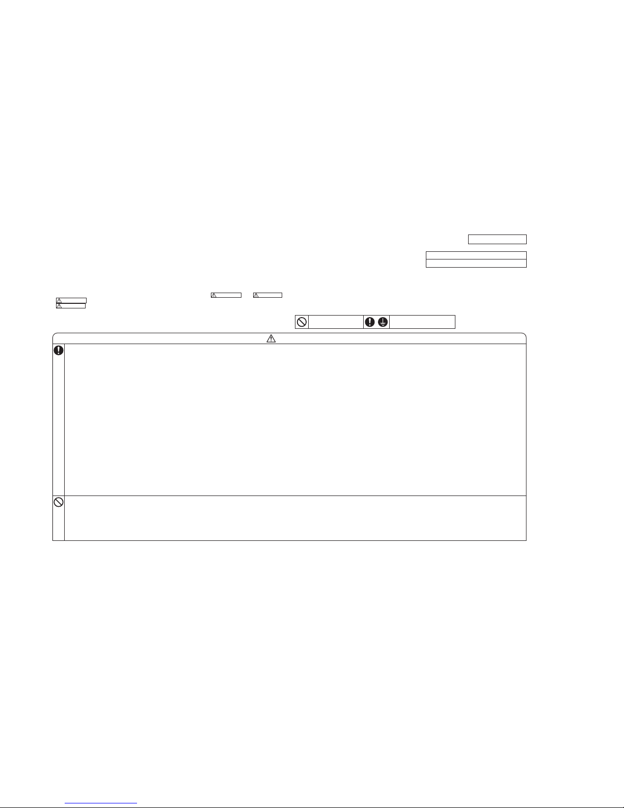
SAFETY PRECAUTIONS
• Read the “SAFETY PRECAUTIONS” carefully first of all and strictly follow it during the installation work in order to
protect yourself.
• The precautionary items mentioned below are distinguished into two levels, and .
: Wrong installation would cause serious consequences such as injuries or death.
: Wrong installation might cause serious consequences depending on circumstances.
Both mentions the important items to protect your health and safety so strictly follow them by any means.
• Be sure to confirm no anomaly on the equipment by commissioning after completed installation and explain the operating methods aswell as the maintenance methods of this equipment to the user according to the owner’s manual.
• Keep the installation manual together with owner’s manual at a place where any user can read at any time.
Moreover if necessary, ask to hand them to a new user.
• For installing qualified personnel, take precautions in respect to themselves by using suitable protective clothing,
groves, etc., and then perform the installation works.
• Please pay attention not to fall down the tools, etc. when installing the unit at the high position.
• If unusual noise can be heard during operation, consult the dealer.
• The meanings of “Marks” used here are shown as follows:
CAUTIONWARNING
CAUTION
WARNING
Never do it under any
circumstances.
Always do it according to the
instruction.
INSTALLATION MANUAL
• When install the unit, be sure to check whether the selection of installation
place, power supply specifications, usage limitation (piping length, height
differences between indoor and outdoor units, power supply voltage and etc.)
and installation spaces.
Intake
The height of a wall is 1200mm or less.
(
service
space
)
L3
L2
L4
Example installation
Size
8. APPLICATION DATA
Models SRK25ZMP-S, 35ZMP-S, 45ZMP-S
 Loading...