

Mitsubishi SRK20ZS-W, SRK 25ZS-WB, SRK20ZS-WB, SRK 25ZS-WT, SRK 35ZS-W Technical Manual
...Page 1

Manual No.'18•SRK-T-250
TECHNICAL MANUAL
INVERTER WALL MOUNTED TYPE
RESIDENTIAL AIR-CONDITIONERS
(Split system, air to air heat pump type)
SRK20ZS-W, -WB, -WT
25ZS-W, -WB, -WT
35ZS-W, -WB, -WT
50ZS-W, -WB, -WT
Page 2

(1) Indoor units ........................................................................................ 16
2. EXTERIOR DIMENSIONS
3. ELECTRICAL WIRING
4. NOISE LEVEL
6. RANGE OF USAGE & LIMITATIONS
7. CAPACITY TABLES
5. PIPING SYSTEM
8. APPLICATION DATA
9. OUTLINE OF OPERATION CONTROL BY MICROCOMPUTER
1. SPECIFICATIONS
(2) Outdoor units......................................................................................... 17
(3) Remote control
'18 • SRK-T-250
CONTENTS
........................................................................................ 3
......................................................................... 16
........................................................................................ 19
.............................................................................. 22
(1) Indoor units ............................................................................................. 22
(2) Outdoor units........................................................................................... 23
................................................................................................. 25
............................................................................................ 43
............................................................. 45
....................................................................................... 47
(1) Installation of indoor unit ......................................................................... 48
(2) Installation of outdoor unit ....................................................................... 56
(3)
Safety precautions in handling air-conditioners with flammable refrigerants
.................................................................................. 48
(1) Operation control function by wireless remote control ............................ 62
(2) Unit ON/OFF button
................................................................................ 63
................................................................................ 63(3) Auto restart function
..................................... 63(4) Installing two air-conditioners in the same room
.... 60
.................. 62
(5) Selection of the annual cooling function.................................................. 64
(6) Heating only function............................................................................... 64
(7) High power operation .............................................................................. 64
(8) Economy operation
................................................................................. 65
(9) Air flow direction adjustment ................................................................... 65
(10) 3D auto operation
(11) Timer operation
................................................................................... 66
....................................................................................... 67
(12) Silent operation....................................................................................... 67
(13) Night setback operation .......................................................................... 67
(14) Air flow range setting .............................................................................. 68
(15) Display brightness adjustment................................................................ 68
(16) Outline of heating operation
(17) Outline of cooling operation
(18) Outline of dehumidifying (DRY) opertaion
(19) Outline of automatic operation
.................................................................... 69
.................................................................... 70
.............................................. 71
................................................................ 71
-
-
1
Page 3

'18 • SRK-T-250
(20) Protective control function
10. MAINTENANCE DATA
(1) Cautions
.................................................................................................. 79
................................................................................... 79
....................................................................... 72
(2) Items to check before troubleshooting .................................................... 79
(3) Troubleshooting procedure
(If the air-conditioner does not run at all)
(4) Troubleshooting procedure (If the air-conditioner runs)
.......................... 80
........... 79
(5) Self-diagnosis table................................................................................. 81
(6) Service mode (Trouble mode access function)....................................... 82
(7) Inspection procedures corresponding to detail of trouble ....................... 90
(8)
Phenomenon observed after short-circuit, wire breakage on sensor
(9) Checking the indoor electrical equipment
.............................................. 95
........... 95
(10) How to make sure of wireless remote control ......................................... 97
(11) Inspection procedure for blown fuse on the indoor and outdoor PCB .... 97
(12) Outdoor unit inspection points ................................................................ 98
11. OPTION PARTS
(1) Wired remote control
........................................................................................... 101
............................................................................ 101
(2) Interface kit (SC-BIKN2-E)
.................................................................... 117
(3) Superlink E board (SC-ADNA-E) ........................................................... 121
12. TECHNICAL INFORMATION
....................................................................... 123
■How to read the model name
Example: SRK 20 Z
S-W
Series code
Inverter type
Product capacity (Cooling capacity : 2.0kW)
Model name SRK : Wall mounted type
SRC : Outdoor unit
-
-
2
Page 4

'18 • SRK-T-250
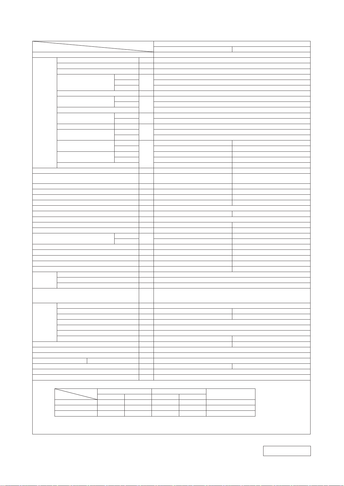
1. SPECIFICATIONS
Item
Power source 1 Phase, 220 - 240V, 50Hz / 220V, 60Hz
Operation
data
Exterior dimensions (Height x Width x Depth) mm 290 x 870 x 230 540 x 780(+62) x 290
Exterior appearance
(Equivalent color : Munsell, RAL)
Net weight kg 9.5 31.5
Compressor type & Quantity — RM-C5077SBE71( Rotary type ) x 1
Compressor motor (Starting method) kW — 0.75 ( Inverter driven )
Refrigerant oil (Amount, type) ℓ — 0.30 ( DIAMOND FREEZE MB75 )
Refrigerant (Type, amount, pre-charge length) kg R32 0.62 in outdoor unit (Incl. the amount for the piping of 15m )
Heat exchanger Louver fins & inner grooved tubing M fins & inner grooved tubing
Refrigerant control Capillary tubes + Electronic expansion valve
Fan type & Quantity Tangential fan x 1 Propeller fan x 1
Fan motor (Starting method) W 42 x1 (Direct drive) 24 x1 (Direct drive)
Air flow
Available external static pressure Pa 0 0
Outside air intake Not possible —
Air filter, Quality / Quantity Polypropylene net (Washable) x 2 —
Shock & vibration absorber Rubber sleeve (for fan motor)
Electric heater — —
Operation
control
Safety equipments
Installation
data
Drain pump, max lift height mm — —
Recommended breaker size A 16
L.R.A. (Locked rotor ampere) A 3.2 / 3.0 / 2.9 (220/ 230/ 240V)
Interconnecting wires Size x Core number 1.5mm
IP number IPX0 IPX4
Standard accessories
Option parts Interface kit ( SC-BIKN2-E )
Nominal cooling capacity (range) kW 2.0 ( 0.9 (Min.) - 2.9 (Max.))
Nominal heating capacity (range) kW 2.7 ( 0.9 (Min.) - 4.3 (Max.))
Heating capacity (H2) kW —
Power consumption
Max power consumption 1.65
Running current
Inrush current, max current 3.2 / 3.0 / 2.9 (220/ 230/ 240V)
Power factor
EER Cooling 4.55
COP
Sound power level
Sound pressure level
Silent mode sound pressure level — Cooling:42 / Heating:43
Remote control Wireless remote control
Room temperature control Microcomputer thermostat
Operation display RUN: Green, TIMER: Yellow
Refrigerant piping size (O.D) mm Liquid line: φ6.35 (1/4") Gas line: φ9.52 (3/8")
Connecting method Flare connection Flare connection
Attached length of piping m Liquid line : 0.54 / Gas line : 0.47 —
Insulation for piping Necessary ( Both sides ), independent
Refrigerant line (one way) length m Max.20
Vertical height diff. between O.U. and I.U. m Max.10 ( Outdoor unit is higher ) / Max.10 ( Outdoor unit is lower )
Drain hose Hose connectable ( VP 16 ) Hole φ20 x 2 pcs
Cooling
Heating 0.59 ( 0.20 - 1.40 )
Heating (H2) —
Cooling
Heating 3.2 / 3.0 / 2.9 (220/ 230/ 240V)
Cooling
Heating 85
Heating 4.58
Heating (H2) —
Cooling
Heating 50 56
Cooling Hi: 34 Me: 25 Lo: 22 ULo: 19 45
Heating Hi: 36 Me: 29 Lo: 23 ULo: 19 45
Cooling
Heating Hi: 10.0 Me: 8.5 Lo: 6.5 ULo: 5.9 23.6
Model
kW
A
%
dB(A)
3
m
/min
Indoor unit SRK20ZS-W Outdoor unit SRC20ZS-W
48 56
Fine snow (Pure white)
( 8.0Y 9.3/0.1 ) , ( 9003 )
Hi: 9.3 Me: 7.0 Lo: 5.9 ULo: 5.0 27.4
Frost protection, Serial signal error protection, Indoor fan motor error protection,
Heating overload protection( High pressure control ), Cooling overload protection
Mounting kit, Clean filter ( Allergen clear filter x 1, Photocatalytic washable deodorizing filter x 1 )
Compressor overheat protection, Overcurrent protection,
2
x 4 cores (Including earth cable) / Terminal block (Screw fixing type)
Notes (1) The data are measured at the following conditions.
Indoor air temperature Outdoor air temperature
Operation
Cooling 27˚C 19˚C 35˚C 24˚C ISO5151-T1
Heating 20˚C — 7˚C 6˚C ISO5151-H1
Heating (H2) 20˚C — 2˚C 1˚C ISO5151-H2
Item
DB WB DB WB
(2) This air-conditioner is manufactured and tested in conformity with the ISO.
(3) Sound level indicates the value in an anechoic chamber. During operation these values are somewhat higher due to ambient conditions.
(4) Select the breaker size according to the own national standard.
SRK20ZS-W
0.44 ( 0.19 - 0.80 )
2.6 / 2.5 / 2.4 (220/ 230/ 240V)
79
( 4.2Y 7.5/1.1 ) , ( 7044 )
Rubber sleeve (for fan motor & compressor)
The pipe length is 5m.
Standards
Max. 9
Stucco white
RWA000Z274
-
-
3
Page 5

'18 • SRK-T-250
Item
Power source 1 Phase, 220 - 240V, 50Hz / 220V, 60Hz
Operation
data
Exterior dimensions (Height x Width x Depth) mm 290 x 870 x 230 540 x 780(+62) x 290
Exterior appearance
(Equivalent color : Munsell, RAL)
Net weight kg 9.5 31.0
Compressor type & Quantity — RM-C5077SBE71( Rotary type ) x 1
Compressor motor (Starting method) kW — 0.75 ( Inverter driven )
Refrigerant oil (Amount, type) ℓ — 0.30 ( DIAMOND FREEZE MB75 )
Refrigerant (Type, amount, pre-charge length) kg R32 0.62 in outdoor unit (Incl. the amount for the piping of 15m )
Heat exchanger Louver fins & inner grooved tubing M fins & inner grooved tubing
Refrigerant control Capillary tubes + Electronic expansion valve
Fan type & Quantity Tangential fan x 1 Propeller fan x 1
Fan motor (Starting method) W 42 x1 (Direct drive) 24 x1 (Direct drive)
Air flow
Available external static pressure Pa 0 0
Outside air intake Not possible —
Air filter, Quality / Quantity Polypropylene net (Washable) x 2 —
Shock & vibration absorber Rubber sleeve (for fan motor)
Electric heater — —
Operation
control
Safety equipments
Installation
data
Drain pump, max lift height mm — —
Recommended breaker size A 16
L.R.A. (Locked rotor ampere) A 3.7 / 3.6 / 3.4 (220/ 230/ 240V)
Interconnecting wires Size x Core number 1.5mm
IP number IPX0 IPX4
Standard accessories
Option parts Interface kit ( SC-BIKN2-E )
Nominal cooling capacity (range) kW 2.5 ( 0.9 (Min.) - 3.1 (Max.))
Nominal heating capacity (range) kW 3.2 ( 0.9 (Min.) - 4.5 (Max.))
Heating capacity (H2) kW —
Power consumption
Max power consumption 1.65
Running current
Inrush current, max current 3.7 / 3.6 / 3.4 (220/ 230/ 240V)
Power factor
EER Cooling 4.03
COP
Sound power level
Sound pressure level
Silent mode sound pressure level — Cooling:42 / Heating:43
Remote control Wireless-remote control
Room temperature control Microcomputer thermostat
Operation display RUN: Green , TIMER: Yellow
Refrigerant piping size (O.D) mm Liquid line: φ6.35 (1/4") Gas line: φ9.52 (3/8")
Connecting method Flare connection Flare connection
Attached length of piping m Liquid line : 0.54 / Gas line : 0.47 —
Insulation for piping Necessary ( Both sides ), independent
Refrigerant line (one way) length m Max.20
Vertical height diff. between O.U. and I.U. m Max.10 ( Outdoor unit is higher ) / Max.10 ( Outdoor unit is lower )
Drain hose Hose connectable ( VP 16 ) Hole φ20 x 2 pcs
Cooling
Heating 0.74 ( 0.20 - 1.42 )
Heating (H2) —
Cooling
Heating 3.7 / 3.6 / 3.4 (220/ 230/ 240V)
Cooling
Heating 90
Heating 4.32
Heating (H2) —
Cooling
Heating 53 58
Cooling Hi: 34 Me: 25 Lo: 22 ULo: 19 46
Heating Hi: 36 Me: 29 Lo: 23 ULo: 19 46
Cooling
Heating Hi: 11.3 Me: 8.7 Lo: 6.7 ULo: 5.9 23.6
Model
kW
A
%
dB(A)
3
m
/min
Indoor unit SRK25ZS-W Outdoor unit SRC25ZS-W
50 56
Fine snow (Pure white)
( 8.0Y 9.3/0.1 ) , ( 9003 )
Hi: 9.9 Me: 8.0 Lo: 5.9 ULo: 5.0 27.4
Frost protection, Serial signal error protection, Indoor fan motor error protection,
Heating overload protection( High pressure control ), Cooling overload protection
Mounting kit, Clean filter ( Allergen clear filter x 1, Photocatalytic washable deodorizing filter x 1 )
Compressor overheat protection, Overcurrent protection,
2
x 4 cores (Including earth cable) / Terminal block (Screw fixing type)
Notes (1) The data are measured at the following conditions.
Indoor air temperature Outdoor air temperature
Operation
Cooling 27˚C 19˚C 35˚C 24˚C ISO5151-T1
Heating 20˚C — 7˚C 6˚C ISO5151-H1
Heating (H2) 20˚C — 2˚C 1˚C ISO5151-H2
Item
DB WB DB WB
SRK25ZS-W
0.62 ( 0.19 - 0.90 )
3.3 / 3.1 / 3.0 (220/ 230/ 240V)
86
( 4.2Y 7.5/1.1 ) , ( 7044 )
Rubber sleeve (for fan motor & compressor)
The pipe length is 5m.
Standards
Max. 9
Stucco white
(2) This air-conditioner is manufactured and tested in conformity with the ISO.
(3) Sound level indicates the value in an anechoic chamber. During operation these values are somewhat higher due to ambient conditions.
(4) Select the breaker size according to the own national standard.
RWA000Z274
-
-
4
Page 6
'18 • SRK-T-250
Item
Power source 1 Phase, 220 - 240V, 50Hz / 220V, 60Hz
Operation
data
Exterior dimensions (Height x Width x Depth) mm 290 x 870 x 230 540 x 780(+62) x 290
Exterior appearance
(Equivalent color : Munsell, RAL)
Net weight kg 9.5 34.5
Compressor type & Quantity — RM-B5077SBE2( Rotary type ) x 1
Compressor motor (Starting method) kW — 0.90 ( Inverter driven )
Refrigerant oil (Amount, type) ℓ — 0.30 ( DIAMOND FREEZE MB75 )
Refrigerant (Type, amount, pre-charge length) kg R32 0.78 in outdoor unit (Incl. the amount for the piping of 15m )
Heat exchanger Louver fins & inner grooved tubing M fins & inner grooved tubing
Refrigerant control Capillary tubes + Electronic expansion valve
Fan type & Quantity Tangential fan x 1 Propeller fan x 1
Fan motor (Starting method) W 42 x1 (Direct drive) 24 x1 (Direct drive)
Air flow
Available external static pressure Pa 0 0
Outside air intake Not possible —
Air filter, Quality / Quantity Polypropylene net (Washable) x 2 —
Shock & vibration absorber Rubber sleeve (for fan motor)
Electric heater — —
Operation
control
Safety equipments
Installation
data
Drain pump, max lift height mm — —
Recommended breaker size A 16
L.R.A. (Locked rotor ampere) A 4.6 / 4.4 / 4.2 (220/ 230/ 240V)
Interconnecting wires Size x Core number 1.5mm
IP number IPX0 IPX4
Standard accessories
Option parts Interface kit ( SC-BIKN2-E )
Nominal cooling capacity (range) kW 3.5 ( 0.9 (Min.) - 4.0 (Max.))
Nominal heating capacity (range) kW 4.0 ( 0.9 (Min.) - 5.0 (Max.))
Heating capacity (H2) kW —
Power consumption
Max power consumption 1.65
Running current
Inrush current, max current 4.6 / 4.4 / 4.2 (220/ 230/ 240V)
Power factor
EER Cooling 3.93
COP
Sound power level
Sound pressure level
Silent mode sound pressure level — Cooling:45 / Heating:44
Remote control Wireless-remote control
Room temperature control Microcomputer thermostat
Operation display RUN: Green , TIMER: Yellow
Refrigerant piping size (O.D) mm Liquid line: φ6.35 (1/4") Gas line: φ9.52 (3/8")
Connecting method Flare connection Flare connection
Attached length of piping m Liquid line : 0.54 / Gas line : 0.47 —
Insulation for piping Necessary ( Both sides ), independent
Refrigerant line (one way) length m Max.20
Vertical height diff. between O.U. and I.U. m Max.10 ( Outdoor unit is higher ) / Max.10 ( Outdoor unit is lower )
Drain hose Hose connectable ( VP 16 ) Hole φ20 x 2 pcs
Cooling
Heating 0.94 ( 0.19 - 1.45 )
Heating (H2) —
Cooling
Heating 4.6 / 4.4 / 4.2 (220/ 230/ 240V)
Cooling
Heating 93
Heating 4.26
Heating (H2) —
Cooling
Heating 56 61
Cooling Hi: 40 Me: 30 Lo: 26 ULo: 19 50
Heating Hi: 41 Me: 36 Lo: 25 ULo:19 48
Cooling
Heating Hi: 12.3 Me: 11.0 Lo: 7.0 ULo: 5.6 27.8
Model
kW
A
%
dB(A)
3
m
/min
Indoor unit SRK35ZS-W Outdoor unit SRC35ZS-W
54 61
Fine snow (Pure white)
( 8.0Y 9.3/0.1 ) , ( 9003 )
Hi: 11.3 Me: 8.7 Lo: 7.0 ULo: 5.0 31.5
Frost protection, Serial signal error protection, Indoor fan motor error protection,
Heating overload protection( High pressure control ), Cooling overload protection
Mounting kit, Clean filter ( Allergen clear filter x 1, Photocatalytic washable deodorizing filter x 1 )
Compressor overheat protection, Overcurrent protection,
2
x 4 cores (Including earth cable) / Terminal block (Screw fixing type)
Notes (1) The data are measured at the following conditions.
Indoor air temperature Outdoor air temperature
Operation
Cooling 27˚C 19˚C 35˚C 24˚C ISO5151-T1
Heating 20˚C — 7˚C 6˚C ISO5151-H1
Heating (H2) 20˚C — 2˚C 1˚C ISO5151-H2
Item
DB WB DB WB
SRK35ZS-W
0.89 ( 0.17 - 1.24 )
4.4 / 4.2 / 4.0 (220/ 230/ 240V)
92
( 4.2Y 7.5/1.1 ) , ( 7044 )
Rubber sleeve (for fan motor & compressor)
The pipe length is 5m.
Standards
Max. 9
Stucco white
(2) This air-conditioner is manufactured and tested in conformity with the ISO.
(3) Sound level indicates the value in an anechoic chamber. During operation these values are somewhat higher due to ambient conditions.
(4) Select the breaker size according to the own national standard.
RWA000Z274
-
-
5
Page 7

'18 • SRK-T-250
Item
Power source 1 Phase, 220 - 240V, 50Hz / 220V, 60Hz
Operation
data
Exterior dimensions (Height x Width x Depth) mm 290 x 870 x 230 595 x 780(+62) x 290
Exterior appearance
(Equivalent color : Munsell, RAL)
Net weight kg 10.0 36.0
Compressor type & Quantity — 9RS102XDA21( Rotary type ) x 1
Compressor motor (Starting method) kW — 1.50 ( Inverter driven )
Refrigerant oil (Amount, type) ℓ — 0.32 ( FW50S )
Refrigerant (Type, amount, pre-charge length) kg R32 1.05 in outdoor unit (Incl. the amount for the piping of 15m )
Heat exchanger Louver fins & inner grooved tubing M fins & inner grooved tubing
Refrigerant control Capillary tubes + Electronic expansion valve
Fan type & Quantity Tangential fan x 1 Propeller fan x 1
Fan motor (Starting method) W 42 x1 (Direct drive) 24 x1 (Direct drive)
Air flow
Available external static pressure Pa 0 0
Outside air intake Not possible —
Air filter, Quality / Quantity Polypropylene net (Washable) x 2 —
Shock & vibration absorber Rubber sleeve (for fan motor)
Electric heater — —
Operation
control
Safety equipments
Installation
data
Drain pump, max lift height mm — —
Recommended breaker size A 20
L.R.A. (Locked rotor ampere) A 7.2 / 6.9 / 6.6 (220/ 230/ 240V)
Interconnecting wires Size x Core number 1.5mm
IP number IPX0 IPX4
Standard accessories
Option parts Interface kit ( SC-BIKN2-E )
Nominal cooling capacity (range) kW 5.0 ( 1.3 (Min.) - 5.5 (Max.))
Nominal heating capacity (range) kW 5.8 ( 1.3 (Min.) - 6.6 (Max.))
Heating capacity (H2) kW —
Power consumption
Max power consumption 2.68
Running current
Inrush current, max current 7.2 / 6.9 / 6.6 (220/ 230/ 240V)
Power factor
EER Cooling 3.70
COP
Sound power level
Sound pressure level
Silent mode sound pressure level — Cooling:43 / Heating:45
Remote control Wireless-remote control
Room temperature control Microcomputer thermostat
Operation display RUN: Green , TIMER: Yellow
Refrigerant piping size (O.D) mm Liquid line: φ6.35 (1/4") Gas line: φ12.7 (1/2" )
Connecting method Flare connection Flare connection
Attached length of piping m Liquid line : 0.54 / Gas line : 0.47 —
Insulation for piping Necessary ( Both sides ), independent
Refrigerant line (one way) length m Max.25
Vertical height diff. between O.U. and I.U. m Max.15 ( Outdoor unit is higher ) / Max.15 ( Outdoor unit is lower )
Drain hose Hose connectable ( VP 16 ) Hole φ20 x 2 pcs
Cooling
Heating 1.56 ( 0.25 - 1.98 )
Heating (H2) —
Cooling
Heating 7.2 / 6.9 / 6.6 (220/ 230/ 240V)
Cooling
Heating 99
Heating 3.72
Heating (H2) —
Cooling
Heating 60 63
Cooling Hi: 46 Me: 36 Lo: 29 ULo: 22 51
Heating Hi: 46 Me: 37 Lo: 31 ULo: 24 52
Cooling
Heating Hi: 13.9 Me: 11.2 Lo: 9.1 ULo: 7.4 32.8
Model
kW
A
%
dB(A)
3
m
/min
Indoor unit SRK50ZS-W Outdoor unit SRC50ZS-W
59 61
Fine snow (Pure white)
( 8.0Y 9.3/0.1 ) , ( 9003 )
Hi: 12.1 Me: 9.9 Lo: 7.4 ULo: 5.9 32.8
Frost protection, Serial signal error protection, Indoor fan motor error protection,
Heating overload protection( High pressure control ), Cooling overload protection
Mounting kit, Clean filter ( Allergen clear filter x 1, Photocatalytic washable deodorizing filter x 1 )
Compressor overheat protection, Overcurrent protection,
2
x 4 cores (Including earth cable) / Terminal block (Screw fixing type)
Notes (1) The data are measured at the following conditions.
Indoor air temperature Outdoor air temperature
Operation
Cooling 27˚C 19˚C 35˚C 24˚C ISO5151-T1
Heating 20˚C — 7˚C 6˚C ISO5151-H1
Heating (H2) 20˚C — 2˚C 1˚C ISO5151-H2
Item
DB WB DB WB
SRK50ZS-W
1.35 ( 0.29 - 1.80 )
6.2 / 5.9 / 5.7 (220/ 230/ 240V)
Max. 14.5
99
The pipe length is 5m.
Standards
( 4.2Y 7.5/1.1 ) , ( 7044 )
Rubber sleeve (for fan motor & compressor)
Stucco white
(2) This air-conditioner is manufactured and tested in conformity with the ISO.
(3) Sound level indicates the value in an anechoic chamber. During operation these values are somewhat higher due to ambient conditions.
(4) Select the breaker size according to the own national standard.
RWA000Z274
-
-
6
Page 8

'18 • SRK-T-250
Item
Power source 1 Phase, 220 - 240V, 50Hz / 220V, 60Hz
Operation
data
Exterior dimensions (Height x Width x Depth) mm 290 x 870 x 230 540 x 780(+62) x 290
Exterior appearance
(Equivalent color : Munsell, RAL)
Net weight kg 9.5 31.0
Compressor type & Quantity — RM-C5077SBE71( Rotary type ) x 1
Compressor motor (Starting method) kW — 0.75 ( Inverter driven )
Refrigerant oil (Amount, type) ℓ — 0.30 ( DIAMOND FREEZE MB75 )
Refrigerant (Type, amount, pre-charge length) kg R32 0.6 in outdoor unit (Incl. the amount for the piping of 15m )
Heat exchanger Louver fins & inner grooved tubing M fins & inner grooved tubing
Refrigerant control Capillary tubes + Electronic expansion valve
Fan type & Quantity Tangential fan x 1 Propeller fan x 1
Fan motor (Starting method) W 42 x1 (Direct drive) 24 x1 (Direct drive)
Air flow
Available external static pressure Pa 0 0
Outside air intake Not possible —
Air filter, Quality / Quantity Polypropylene net (Washable) x 2 —
Shock & vibration absorber Rubber sleeve (for fan motor)
Electric heater — —
Operation
control
Safety equipments
Installation
data
Drain pump, max lift height mm — —
Recommended breaker size A 16
L.R.A. (Locked rotor ampere) A 3.2 / 3.0 / 2.9 (220/ 230/ 240V)
Interconnecting wires Size x Core number 1.5mm
IP number IPX0 IPX4
Standard accessories
Option parts Interface kit ( SC-BIKN2-E )
Nominal cooling capacity (range) kW 2.0 ( 0.9 (Min.) - 2.9 (Max.))
Nominal heating capacity (range) kW 2.7 ( 0.9 (Min.) - 4.3 (Max.))
Heating capacity (H2) kW —
Power consumption
Max power consumption 1.65
Running current
Inrush current, max current 3.2 / 3.0 / 2.9 (220/ 230/ 240V)
Power factor
EER Cooling 4.55
COP
Sound power level
Sound pressure level
Silent mode sound pressure level — Cooling:42 / Heating:43
Remote control Wireless-remote control
Room temperature control Microcomputer thermostat
Operation display RUN: Green , TIMER: Yellow
Refrigerant piping size (O.D) mm Liquid line: φ6.35 (1/4") Gas line: φ9.52 (3/8")
Connecting method Flare connection Flare connection
Attached length of piping m Liquid line : 0.54 / Gas line : 0.47 —
Insulation for piping Necessary ( Both sides ), independent
Refrigerant line (one way) length m Max.20
Vertical height diff. between O.U. and I.U. m Max.10 ( Outdoor unit is higher ) / Max.10 ( Outdoor unit is lower )
Drain hose Hose connectable ( VP 16 ) Hole φ20 x 2 pcs
Cooling
Heating 0.59 ( 0.20 - 1.40 )
Heating (H2) —
Cooling
Heating 3.2 / 3.0 / 2.9 (220/ 230/ 240V)
Cooling
Heating 85
Heating 4.58
Heating (H2) —
Cooling
Heating 50 56
Cooling Hi: 34 Me: 25 Lo: 22 ULo: 19 45
Heating Hi: 36 Me: 29 Lo: 23 ULo: 19 45
Cooling
Heating Hi: 10.0 Me: 8.5 Lo: 6.5 ULo: 5.9 23.6
Model
kW
A
%
dB(A)
3
m
/min
Indoor unit SRK20ZS-WB Outdoor unit SRC20ZS-W
48 56
Fine snow ( 8.0Y 9.3/0.1 ) , ( 9003 )
Black ( 4.0PB 2.44/0.25 ) , ( 9011 )
Hi: 9.3 Me: 7.0 Lo: 5.9 ULo: 5.0 27.4
Frost protection, Serial signal error protection, Indoor fan motor error protection,
Heating overload protection( High pressure control ), Cooling overload protection
Mounting kit, Clean filter ( Allergen clear filter x 1, Photocatalytic washable deodorizing filter x 1 )
Compressor overheat protection, Overcurrent protection,
2
x 4 cores (Including earth cable) / Terminal block (Screw fixing type)
Notes (1) The data are measured at the following conditions.
Indoor air temperature Outdoor air temperature
Operation
Cooling 27˚C 19˚C 35˚C 24˚C ISO5151-T1
Heating 20˚C — 7˚C 6˚C ISO5151-H1
Heating (H2) 20˚C — 2˚C 1˚C ISO5151-H2
Item
DB WB DB WB
SRK20ZS-WB
0.44 ( 0.19 - 0.80 )
2.6 / 2.5 / 2.4 (220/ 230/ 240V)
79
( 4.2Y 7.5/1.1 ) , ( 7044 )
Rubber sleeve (for fan motor & compressor)
The pipe length is 5m.
Standards
Max. 9
Stucco white
(2) This air-conditioner is manufactured and tested in conformity with the ISO.
(3) Sound level indicates the value in an anechoic chamber. During operation these values are somewhat higher due to ambient conditions.
(4) Select the breaker size according to the own national standard.
RWA000Z274
-
-
7
Page 9

'18 • SRK-T-250
Item
Power source 1 Phase, 220 - 240V, 50Hz / 220V, 60Hz
Operation
data
Exterior dimensions (Height x Width x Depth) mm 290 x 870 x 230 540 x 780(+62) x 290
Exterior appearance
(Equivalent color : Munsell, RAL)
Net weight kg 9.5 31.0
Compressor type & Quantity — RM-C5077SBE71( Rotary type ) x 1
Compressor motor (Starting method) kW — 0.75 ( Inverter driven )
Refrigerant oil (Amount, type) ℓ — 0.30 ( DIAMOND FREEZE MB75 )
Refrigerant (Type, amount, pre-charge length) kg R32 0.62 in outdoor unit (Incl. the amount for the piping of 15m )
Heat exchanger Louver fins & inner grooved tubing M fins & inner grooved tubing
Refrigerant control Capillary tubes + Electronic expansion valve
Fan type & Quantity Tangential fan x 1 Propeller fan x 1
Fan motor (Starting method) W 42 x1 (Direct drive) 24 x1 (Direct drive)
Air flow
Available external static pressure Pa 0 0
Outside air intake Not possible —
Air filter, Quality / Quantity Polypropylene net (Washable) x 2 —
Shock & vibration absorber Rubber sleeve (for fan motor)
Electric heater — —
Operation
control
Safety equipments
Installation
data
Drain pump, max lift height mm — —
Recommended breaker size A 16
L.R.A. (Locked rotor ampere) A 3.7 / 3.6 / 3.4 (220/ 230/ 240V)
Interconnecting wires Size x Core number 1.5mm
IP number IPX0 IPX4
Standard accessories
Option parts Interface kit ( SC-BIKN2-E )
Nominal cooling capacity (range) kW 2.5 ( 0.9 (Min.) - 3.1 (Max.))
Nominal heating capacity (range) kW 3.2 ( 0.9 (Min.) - 4.5 (Max.))
Heating capacity (H2) kW —
Power consumption
Max power consumption 1.65
Running current
Inrush current, max current 3.7 / 3.6 / 3.4 (220/ 230/ 240V)
Power factor
EER Cooling 4.03
COP
Sound power level
Sound pressure level
Silent mode sound pressure level — Cooling:42 / Heating:43
Remote control Wireless-remote control
Room temperature control Microcomputer thermostat
Operation display RUN: Green , TIMER: Yellow
Refrigerant piping size (O.D) mm Liquid line: φ6.35 (1/4") Gas line: φ9.52 (3/8")
Connecting method Flare connection Flare connection
Attached length of piping m Liquid line : 0.54 / Gas line : 0.47 —
Insulation for piping Necessary ( Both sides ), independent
Refrigerant line (one way) length m Max.20
Vertical height diff. between O.U. and I.U. m Max.10 ( Outdoor unit is higher ) / Max.10 ( Outdoor unit is lower )
Drain hose Hose connectable ( VP 16 ) Hole φ20 x 2 pcs
Cooling
Heating 0.74 ( 0.20 - 1.42 )
Heating (H2) —
Cooling
Heating 3.7 / 3.6 / 3.4 (220/ 230/ 240V)
Cooling
Heating 90
Heating 4.32
Heating (H2) —
Cooling
Heating 53 58
Cooling Hi: 36 Me: 28 Lo: 23 ULo: 19 46
Heating Hi: 39 Me: 30 Lo: 24 ULo: 19 46
Cooling
Heating Hi: 11.3 Me: 8.7 Lo: 6.7 ULo: 5.9 23.6
Model
kW
A
%
dB(A)
3
m
/min
Indoor unit SRK25ZS-WB Outdoor unit SRC25ZS-W
50 56
Fine snow ( 8.0Y 9.3/0.1 ) , ( 9003 )
Black ( 4.0PB 2.44/0.25 ) , ( 9011 )
Hi: 9.9 Me: 8.0 Lo: 5.9 ULo: 5.0 27.4
Frost protection, Serial signal error protection, Indoor fan motor error protection,
Heating overload protection( High pressure control ), Cooling overload protection
Mounting kit, Clean filter ( Allergen clear filter x 1, Photocatalytic washable deodorizing filter x 1 )
Compressor overheat protection, Overcurrent protection,
2
x 4 cores (Including earth cable) / Terminal block (Screw fixing type)
Notes (1) The data are measured at the following conditions.
Indoor air temperature Outdoor air temperature
Operation
Cooling 27˚C 19˚C 35˚C 24˚C ISO5151-T1
Heating 20˚C — 7˚C 6˚C ISO5151-H1
Heating (H2) 20˚C — 2˚C 1˚C ISO5151-H2
Item
DB WB DB WB
SRK25ZS-WB
0.62 ( 0.19 - 0.90 )
3.3 / 3.1 / 3.0 (220/ 230/ 240V)
86
( 4.2Y 7.5/1.1 ) , ( 7044 )
Rubber sleeve (for fan motor & compressor)
The pipe length is 5m.
Standards
Max. 9
Stucco white
(2) This air-conditioner is manufactured and tested in conformity with the ISO.
(3) Sound level indicates the value in an anechoic chamber. During operation these values are somewhat higher due to ambient conditions.
(4) Select the breaker size according to the own national standard.
RWA000Z274
-
-
8
Page 10

'18 • SRK-T-250
Item
Power source 1 Phase, 220 - 240V, 50Hz / 220V, 60Hz
Operation
data
Exterior dimensions (Height x Width x Depth) mm 290 x 870 x 230 540 x 780(+62) x 290
Exterior appearance
(Equivalent color : Munsell, RAL)
Net weight kg 9.5 34.5
Compressor type & Quantity — RM-B5077SBE2( Rotary type ) x 1
Compressor motor (Starting method) kW — 0.90 ( Inverter driven )
Refrigerant oil (Amount, type) ℓ — 0.30 ( DIAMOND FREEZE MB75 )
Refrigerant (Type, amount, pre-charge length) kg R32 0.78 in outdoor unit (Incl. the amount for the piping of 15m )
Heat exchanger Louver fins & inner grooved tubing M fins & inner grooved tubing
Refrigerant control Capillary tubes + Electronic expansion valve
Fan type & Quantity Tangential fan x 1 Propeller fan x 1
Fan motor (Starting method) W 42 x1 (Direct drive) 24 x1 (Direct drive)
Air flow
Available external static pressure Pa 0 0
Outside air intake Not possible —
Air filter, Quality / Quantity Polypropylene net (Washable) x 2 —
Shock & vibration absorber Rubber sleeve (for fan motor)
Electric heater — —
Operation
control
Safety equipments
Installation
data
Drain pump, max lift height mm — —
Recommended breaker size A 16
L.R.A. (Locked rotor ampere) A 4.6 / 4.4 / 4.2 (220/ 230/ 240V)
Interconnecting wires Size x Core number 1.5mm
IP number IPX0 IPX4
Standard accessories
Option parts Interface kit ( SC-BIKN2-E )
Nominal cooling capacity (range) kW 3.5 ( 0.9 (Min.) - 4.0 (Max.))
Nominal heating capacity (range) kW 4.0 ( 0.9 (Min.) - 5.0 (Max.))
Heating capacity (H2) kW —
Power consumption
Max power consumption 1.65
Running current
Inrush current, max current 4.6 / 4.4 / 4.2 (220/ 230/ 240V)
Power factor
EER Cooling 3.93
COP
Sound power level
Sound pressure level
Silent mode sound pressure level — Cooling:45 / Heating:44
Remote control Wireless-remote control
Room temperature control Microcomputer thermostat
Operation display RUN: Green , TIMER: Yellow
Refrigerant piping size (O.D) mm Liquid line: φ6.35 (1/4") Gas line: φ9.52 (3/8")
Connecting method Flare connection Flare connection
Attached length of piping m Liquid line : 0.54 / Gas line : 0.47 —
Insulation for piping Necessary ( Both sides ), independent
Refrigerant line (one way) length m Max.20
Vertical height diff. between O.U. and I.U. m Max.10 ( Outdoor unit is higher ) / Max.10 ( Outdoor unit is lower )
Drain hose Hose connectable ( VP 16 ) Hole φ20 x 2 pcs
Cooling
Heating 0.94 ( 0.19 - 1.45 )
Heating (H2) —
Cooling
Heating 4.6 / 4.4 / 4.2 (220/ 230/ 240V)
Cooling
Heating 93
Heating 4.26
Heating (H2) —
Cooling
Heating 56 61
Cooling Hi: 40 Me: 30 Lo: 26 ULo: 19 50
Heating Hi: 41 Me: 36 Lo: 25 ULo:19 48
Cooling
Heating Hi: 12.3 Me: 11.0 Lo: 7.0 ULo: 5.6 27.8
Model
kW
A
%
dB(A)
3
m
/min
Indoor unit SRK35ZS-WB Outdoor unit SRC35ZS-W
54 61
Fine snow ( 8.0Y 9.3/0.1 ) , ( 9003 )
Black ( 4.0PB 2.44/0.25 ) , ( 9011 )
Hi: 11.3 Me: 8.7 Lo: 7.0 ULo: 5.0 31.5
Frost protection, Serial signal error protection, Indoor fan motor error protection,
Heating overload protection( High pressure control ), Cooling overload protection
Mounting kit, Clean filter ( Allergen clear filter x 1, Photocatalytic washable deodorizing filter x 1 )
Compressor overheat protection, Overcurrent protection,
2
x 4 cores (Including earth cable) / Terminal block (Screw fixing type)
Notes (1) The data are measured at the following conditions.
Indoor air temperature Outdoor air temperature
Operation
Cooling 27˚C 19˚C 35˚C 24˚C ISO5151-T1
Heating 20˚C — 7˚C 6˚C ISO5151-H1
Heating (H2) 20˚C — 2˚C 1˚C ISO5151-H2
Item
DB WB DB WB
SRK35ZS-WB
0.89 ( 0.17 - 1.24 )
4.4 / 4.2 / 4.0 (220/ 230/ 240V)
92
( 4.2Y 7.5/1.1 ) , ( 7044 )
Rubber sleeve (for fan motor & compressor)
The pipe length is 5m.
Standards
Max. 9
Stucco white
(2) This air-conditioner is manufactured and tested in conformity with the ISO.
(3) Sound level indicates the value in an anechoic chamber. During operation these values are somewhat higher due to ambient conditions.
(4) Select the breaker size according to the own national standard.
RWA000Z274
-
-
9
Page 11

'18 • SRK-T-250
Item
Power source 1 Phase, 220 - 240V, 50Hz / 220V, 60Hz
Operation
data
Exterior dimensions (Height x Width x Depth) mm 290 x 870 x 230 595 x 780(+62) x 290
Exterior appearance
(Equivalent color : Munsell, RAL)
Net weight kg 10.0 36.0
Compressor type & Quantity — 9RS102XDA21( Rotary type ) x 1
Compressor motor (Starting method) kW — 1.50 ( Inverter driven )
Refrigerant oil (Amount, type) ℓ — 0.32 ( FW50S )
Refrigerant (Type, amount, pre-charge length) kg R32 1.05 in outdoor unit (Incl. the amount for the piping of 15m )
Heat exchanger Louver fins & inner grooved tubing M fins & inner grooved tubing
Refrigerant control Capillary tubes + Electronic expansion valve
Fan type & Quantity Tangential fan x 1 Propeller fan x 1
Fan motor (Starting method) W 42 x1 (Direct drive) 24 x1 (Direct drive)
Air flow
Available external static pressure Pa 0 0
Outside air intake Not possible —
Air filter, Quality / Quantity Polypropylene net (Washable) x 2 —
Shock & vibration absorber Rubber sleeve (for fan motor)
Electric heater — —
Operation
control
Safety equipments
Installation
data
Drain pump, max lift height mm — —
Recommended breaker size A 20
L.R.A. (Locked rotor ampere) A 7.2 / 6.9 / 6.6 (220/ 230/ 240V)
Interconnecting wires Size x Core number 1.5mm
IP number IPX0 IPX4
Standard accessories
Option parts Interface kit ( SC-BIKN2-E )
Nominal cooling capacity (range) kW 5.0 ( 1.3 (Min.) - 5.5 (Max.))
Nominal heating capacity (range) kW 5.8 ( 1.3 (Min.) - 6.6 (Max.))
Heating capacity (H2) kW —
Power consumption
Max power consumption 2.68
Running current
Inrush current, max current 7.2 / 6.9 / 6.6 (220/ 230/ 240V)
Power factor
EER Cooling 3.70
COP
Sound power level
Sound pressure level
Silent mode sound pressure level — Cooling:43 / Heating:45
Remote control Wireless-remote control
Room temperature control Microcomputer thermostat
Operation display RUN: Green , TIMER: Yellow
Refrigerant piping size (O.D) mm Liquid line: φ6.35 (1/4") Gas line: φ12.7 (1/2" )
Connecting method Flare connection Flare connection
Attached length of piping m Liquid line : 0.54 / Gas line : 0.47 —
Insulation for piping Necessary ( Both sides ), independent
Refrigerant line (one way) length m Max.25
Vertical height diff. between O.U. and I.U. m Max.15 ( Outdoor unit is higher ) / Max.15 ( Outdoor unit is lower )
Drain hose Hose connectable ( VP 16 ) Hole φ20 x 2 pcs
Cooling
Heating 1.56 ( 0.25 - 1.98 )
Heating (H2) —
Cooling
Heating 7.2 / 6.9 / 6.6 (220/ 230/ 240V)
Cooling
Heating 99
Heating 3.72
Heating (H2) —
Cooling
Heating 60 63
Cooling Hi: 46 Me: 36 Lo: 29 ULo: 22 51
Heating Hi: 46 Me: 37 Lo: 31 ULo: 24 52
Cooling
Heating Hi: 13.9 Me: 11.2 Lo: 9.1 ULo: 7.4 32.8
Model
kW
A
%
dB(A)
3
m
/min
Indoor unit SRK50ZS-WB Outdoor unit SRC50ZS-W
59 61
Fine snow ( 8.0Y 9.3/0.1 ) , ( 9003 )
Black ( 4.0PB 2.44/0.25 ) , ( 9011 )
Hi: 12.1 Me: 9.9 Lo: 7.4 ULo: 5.9 32.8
Frost protection, Serial signal error protection, Indoor fan motor error protection,
Heating overload protection( High pressure control ), Cooling overload protection
Mounting kit, Clean filter ( Allergen clear filter x 1, Photocatalytic washable deodorizing filter x 1 )
Compressor overheat protection, Overcurrent protection,
2
x 4 cores (Including earth cable) / Terminal block (Screw fixing type)
Notes (1) The data are measured at the following conditions.
Indoor air temperature Outdoor air temperature
Operation
Cooling 27˚C 19˚C 35˚C 24˚C ISO5151-T1
Heating 20˚C — 7˚C 6˚C ISO5151-H1
Heating (H2) 20˚C — 2˚C 1˚C ISO5151-H2
Item
DB WB DB WB
SRK50ZS-WB
1.35 ( 0.29 - 1.80 )
6.2 / 5.9 / 5.7 (220/ 230/ 240V)
Max. 14.5
99
The pipe length is 5m.
Standards
( 4.2Y 7.5/1.1 ) , ( 7044 )
Rubber sleeve (for fan motor & compressor)
Stucco white
(2) This air-conditioner is manufactured and tested in conformity with the ISO.
(3) Sound level indicates the value in an anechoic chamber. During operation these values are somewhat higher due to ambient conditions.
(4) Select the breaker size according to the own national standard.
-
10
RWA000Z274
-
Page 12

'18 • SRK-T-250
Item
Power source 1 Phase, 220 - 240V, 50Hz / 220V, 60Hz
Operation
data
Exterior dimensions (Height x Width x Depth) mm 290 x 870 x 230 540 x 780(+62) x 290
Exterior appearance
(Equivalent color : Munsell, RAL)
Net weight kg 9.5 31.0
Compressor type & Quantity — 9RS102XDA21( Rotary type ) x 1
Compressor motor (Starting method) kW — 1.50 ( Inverter driven )
Refrigerant oil (Amount, type) ℓ — 0.32 ( FW50S )
Refrigerant (Type, amount, pre-charge length) kg R32 0.62 in outdoor unit (Incl. the amount for the piping of 15m )
Heat exchanger 0 M fins & inner grooved tubing
Refrigerant control Capillary tubes + Electronic expansion valve
Fan type & Quantity Tangential fan x 1 Propeller fan x 1
Fan motor (Starting method) W 42 x1 (Direct drive) 24 x1 (Direct drive)
Air flow
Available external static pressure Pa 0 0
Outside air intake Not possible —
Air filter, Quality / Quantity Polypropylene net (Washable) x 2 —
Shock & vibration absorber Rubber sleeve (for fan motor)
Electric heater — —
Operation
control
Safety equipments
Installation
data
Drain pump, max lift height mm — —
Recommended breaker size A 16
L.R.A. (Locked rotor ampere) A 3.2 / 3.0 / 2.9 (220/ 230/ 240V)
Interconnecting wires Size x Core number 1.5mm
IP number IPX0 IPX4
Standard accessories
Option parts Interface kit ( SC-BIKN2-E )
Nominal cooling capacity (range) kW 2.0 ( 0.9 (Min.) - 2.9 (Max.))
Nominal heating capacity (range) kW 2.7 ( 0.9 (Min.) - 4.3 (Max.))
Heating capacity (H2) kW —
Power consumption
Max power consumption 1.65
Running current
Inrush current, max current 3.2 / 3.0 / 2.9 (220/ 230/ 240V)
Power factor
EER Cooling 4.55
COP
Sound power level
Sound pressure level
Silent mode sound pressure level — Cooling:43 / Heating:45
Remote control Wireless-remote control
Room temperature control Microcomputer thermostat
Operation display RUN: Green , TIMER: Yellow
Refrigerant piping size (O.D) mm Liquid line: φ6.35 (1/4") Gas line: φ9.52 (3/8")
Connecting method Flare connection Flare connection
Attached length of piping m Liquid line : 0.54 / Gas line : 0.47 —
Insulation for piping Necessary ( Both sides ), independent
Refrigerant line (one way) length m Max.20
Vertical height diff. between O.U. and I.U. m Max.10 ( Outdoor unit is higher ) / Max.10 ( Outdoor unit is lower )
Drain hose Hose connectable ( VP 16 ) Hole φ20 x 2 pcs
Cooling
Heating 0.59 ( 0.20 - 1.40 )
Heating (H2) —
Cooling
Heating 3.2 / 3.0 / 2.9 (220/ 230/ 240V)
Cooling
Heating 85
Heating 4.58
Heating (H2) —
Cooling
Heating 50 56
Cooling Hi: 34 Me: 25 Lo: 22 ULo: 19 45
Heating Hi: 36 Me: 29 Lo: 23 ULo: 19 45
Cooling
Heating Hi: 10.0 Me: 8.5 Lo: 6.5 ULo: 5.9 23.6
Model
kW
A
%
dB(A)
3
m
/min
Indoor unit SRK20ZS-WT Outdoor unit SRC20ZS-W
48 56
Titanium gray ( 1.6Y 6.59/0.63 ) , ( 7048 )
Black ( 4.0PB 2.44/0.25 ) , ( 9011 )
Hi: 9.3 Me: 7.0 Lo: 5.9 ULo: 5.0 27.4
Frost protection, Serial signal error protection, Indoor fan motor error protection,
Heating overload protection( High pressure control ), Cooling overload protection
Mounting kit, Clean filter ( Allergen clear filter x 1, Photocatalytic washable deodorizing filter x 1 )
Compressor overheat protection, Overcurrent protection,
2
x 4 cores (Including earth cable) / Terminal block (Screw fixing type)
Notes (1) The data are measured at the following conditions.
Indoor air temperature Outdoor air temperature
Operation
Cooling 27˚C 19˚C 35˚C 24˚C ISO5151-T1
Heating 20˚C — 7˚C 6˚C ISO5151-H1
Heating (H2) 20˚C — 2˚C 1˚C ISO5151-H2
Item
DB WB DB WB
SRK20ZS-WT
0.44 ( 0.19 - 0.80 )
2.6 / 2.5 / 2.4 (220/ 230/ 240V)
79
( 4.2Y 7.5/1.1 ) , ( 7044 )
Rubber sleeve (for fan motor & compressor)
The pipe length is 5m.
Standards
Max. 9
Stucco white
(2) This air-conditioner is manufactured and tested in conformity with the ISO.
(3) Sound level indicates the value in an anechoic chamber. During operation these values are somewhat higher due to ambient conditions.
(4) Select the breaker size according to the own national standard.
-
11
RWA000Z274
-
Page 13

'18 • SRK-T-250
Item
Power source 1 Phase, 220 - 240V, 50Hz / 220V, 60Hz
Operation
data
Exterior dimensions (Height x Width x Depth) mm 290 x 870 x 230 540 x 780(+62) x 290
Exterior appearance
(Equivalent color : Munsell, RAL)
Net weight kg 9.5 31.0
Compressor type & Quantity — RM-C5077SBE71( Rotary type )
Compressor motor (Starting method) kW — 0.75 ( Inverter driven )
Refrigerant oil (Amount, type) ℓ — 0.30 ( DIAMOND FREEZE MB75 )
Refrigerant (Type, amount, pre-charge length) kg R32 0.62 in outdoor unit (Incl. the amount for the piping of 15m )
Heat exchanger Louver fins & inner grooved tubing M fins & inner grooved tubing
Refrigerant control Capillary tubes + Electronic expansion valve
Fan type & Quantity Tangential fan x 1 Propeller fan x 1
Fan motor (Starting method) W 42 x1 (Direct drive) 24 x1 (Direct drive)
Air flow
Available external static pressure Pa 0 0
Outside air intake Not possible —
Air filter, Quality / Quantity Polypropylene net (Washable) x 2 —
Shock & vibration absorber Rubber sleeve (for fan motor)
Electric heater — —
Operation
control
Safety equipments
Installation
data
Drain pump, max lift height mm — —
Recommended breaker size A 16
L.R.A. (Locked rotor ampere) A 3.2 / 3.0 / 2.9 (220/ 230/ 240V)
Interconnecting wires Size x Core number 1.5mm
IP number IPX0 IPX4
Standard accessories
Option parts Interface kit ( SC-BIKN2-E )
Nominal cooling capacity (range) kW 2.5 ( 0.9 (Min.) - 3.1 (Max.))
Nominal heating capacity (range) kW 3.2 ( 0.9 (Min.) - 4.5 (Max.))
Heating capacity (H2) kW —
Power consumption
Max power consumption 1.65
Running current
Inrush current, max current 3.7 / 3.6 / 3.4 (220/ 230/ 240V)
Power factor
EER Cooling 4.03
COP
Sound power level
Sound pressure level
Silent mode sound pressure level — Cooling:42 / Heating:43
Remote control Wireless-remote control
Room temperature control Microcomputer thermostat
Operation display RUN: Green , TIMER: Yellow
Refrigerant piping size (O.D) mm Liquid line: φ6.35 (1/4") Gas line: φ9.52 (3/8")
Connecting method Flare connection Flare connection
Attached length of piping m Liquid line : 0.54 / Gas line : 0.47 —
Insulation for piping Necessary ( Both sides ), independent
Refrigerant line (one way) length m Max.20
Vertical height diff. between O.U. and I.U. m Max.10 ( Outdoor unit is higher ) / Max.10 ( Outdoor unit is lower )
Drain hose Hose connectable ( VP 16 ) Hole φ20 x 2 pcs
Cooling
Heating 0.74 ( 0.20 - 1.42 )
Heating (H2) —
Cooling
Heating 3.7 / 3.6 / 3.4 (220/ 230/ 240V)
Cooling
Heating 90
Heating 4.32
Heating (H2) —
Cooling
Heating 53 58
Cooling Hi: 36 Me: 28 Lo: 23 ULo: 19 46
Heating Hi: 39 Me: 30 Lo: 24 ULo: 19 46
Cooling
Heating Hi: 11.3 Me: 8.7 Lo: 6.7 ULo: 5.9 23.6
Model
kW
A
%
dB(A)
3
m
/min
Indoor unit SRK25ZS-WT Outdoor unit SRC25ZS-W
50 56
Titanium gray ( 1.6Y 6.59/0.63 ) , ( 7048 )
Black ( 4.0PB 2.44/0.25 ) , ( 9011 )
Hi: 9.9 Me: 8.0 Lo: 5.9 ULo: 5.0 27.4
Frost protection, Serial signal error protection, Indoor fan motor error protection,
Heating overload protection( High pressure control ), Cooling overload protection
Mounting kit, Clean filter ( Allergen clear filter x 1, Photocatalytic washable deodorizing filter x 1 )
Compressor overheat protection, Overcurrent protection,
2
x 4 cores (Including earth cable) / Terminal block (Screw fixing type)
Notes (1) The data are measured at the following conditions.
Indoor air temperature Outdoor air temperature
Operation
Cooling 27˚C 19˚C 35˚C 24˚C ISO5151-T1
Heating 20˚C — 7˚C 6˚C ISO5151-H1
Heating (H2) 20˚C — 2˚C 1˚C ISO5151-H2
Item
DB WB DB WB
SRK25ZS-WT
0.62 ( 0.19 - 0.90 )
3.3 / 3.1 / 3.0 (220/ 230/ 240V)
86
( 4.2Y 7.5/1.1 ) , ( 7044 )
Rubber sleeve (for fan motor & compressor)
The pipe length is 5m.
Standards
Max. 9
Stucco white
(2) This air-conditioner is manufactured and tested in conformity with the ISO.
(3) Sound level indicates the value in an anechoic chamber. During operation these values are somewhat higher due to ambient conditions.
(4) Select the breaker size according to the own national standard.
-
12
RWA000Z274
-
Page 14

'18 • SRK-T-250
Item
Power source 1 Phase, 220 - 240V, 50Hz / 220V, 60Hz
Operation
data
Exterior dimensions (Height x Width x Depth) mm 290 x 870 x 230 540 x 780(+62) x 290
Exterior appearance
(Equivalent color : Munsell, RAL)
Net weight kg 9.5 34.5
Compressor type & Quantity — RM-B5077SBE2( Rotary type ) x 1
Compressor motor (Starting method) kW — 0.90 ( Inverter driven )
Refrigerant oil (Amount, type) ℓ — 0.30 ( DIAMOND FREEZE MB75 )
Refrigerant (Type, amount, pre-charge length) kg R32 0.78 in outdoor unit (Incl. the amount for the piping of 15m )
Heat exchanger Louver fins & inner grooved tubing M fins & inner grooved tubing
Refrigerant control Capillary tubes + Electronic expansion valve
Fan type & Quantity Tangential fan x 1 Propeller fan x 1
Fan motor (Starting method) W 42 x1 (Direct drive) 24 x1 (Direct drive)
Air flow
Available external static pressure Pa 0 0
Outside air intake Not possible —
Air filter, Quality / Quantity Polypropylene net (Washable) x 2 —
Shock & vibration absorber Rubber sleeve (for fan motor)
Electric heater — —
Operation
control
Safety equipments
Installation
data
Drain pump, max lift height mm — —
Recommended breaker size A 16
L.R.A. (Locked rotor ampere) A 4.6 / 4.4 / 4.2 (220/ 230/ 240 V)
Interconnecting wires Size x Core number 1.5mm
IP number IPX0 IPX4
Standard accessories
Option parts Interface kit ( SC-BIKN2-E )
Nominal cooling capacity (range) kW 3.5 ( 0.9 (Min.) - 4.0 (Max.))
Nominal heating capacity (range) kW 4.0 ( 0.9 (Min.) - 5.0 (Max.))
Heating capacity (H2) kW —
Power consumption
Max power consumption 1.65
Running current
Inrush current, max current 4.6 / 4.4 / 4.2 (220/ 230/ 240 V) Max. 9
Power factor
EER Cooling 3.93
COP
Sound power level
Sound pressure level
Silent mode sound pressure level — Cooling:45 / Heating:44
Remote control Wireless-remote control
Room temperature control Microcomputer thermostat
Operation display RUN: Green , TIMER: Yellow
Refrigerant piping size (O.D) mm Liquid line: φ6.35 (1/4") Gas line: φ9.52 (3/8")
Connecting method Flare connection Flare connection
Attached length of piping m Liquid line : 0.54 / Gas line : 0.47 —
Insulation for piping Necessary ( Both sides ), independent
Refrigerant line (one way) length m Max.20
Vertical height diff. between O.U. and I.U. m Max.10 ( Outdoor unit is higher ) / Max.10 ( Outdoor unit is lower )
Drain hose Hose connectable ( VP 16 ) Hole φ20 x 2 pcs
Cooling
Heating 0.94 ( 0.19 - 1.45 )
Heating (H2) —
Cooling
Heating 4.6 / 4.4 / 4.2 (220/ 230/ 240V)
Cooling
Heating 93
Heating 4.26
Heating (H2) —
Cooling
Heating 56 61
Cooling Hi: 40 Me: 30 Lo: 26 ULo: 19 50
Heating Hi: 41 Me: 36 Lo: 25 ULo:19 48
Cooling
Heating Hi: 12.3 Me: 11.0 Lo: 7.0 ULo: 5.6 27.8
Model
kW
A
%
dB(A)
3
m
/min
Indoor unit SRK35ZS-WT Outdoor unit SRC35ZS-W
54 61
Titanium gray ( 1.6Y 6.59/0.63 ) , ( 7048 )
Black ( 4.0PB 2.44/0.25 ) , ( 9011 )
Hi: 11.3 Me: 8.7 Lo: 7.0 ULo: 5.0 31.5
Frost protection, Serial signal error protection, Indoor fan motor error protection,
Heating overload protection( High pressure control ), Cooling overload protection
Mounting kit, Clean filter ( Allergen clear filter x 1, Photocatalytic washable deodorizing filter x 1 )
Compressor overheat protection, Overcurrent protection,
2
x 4 cores (Including earth cable) / Terminal block (Screw fixing type)
Notes (1) The data are measured at the following conditions.
Indoor air temperature Outdoor air temperature
Operation
Cooling 27˚C 19˚C 35˚C 24˚C ISO5151-T1
Heating 20˚C — 7˚C 6˚C ISO5151-H1
Heating (H2) 20˚C — 2˚C 1˚C ISO5151-H2
Item
DB WB DB WB
SRK35ZS-WT
0.89 ( 0.17 - 1.24 )
4.4 / 4.2 / 4.0 (220/ 230/ 240V)
92
( 4.2Y 7.5/1.1 ) , ( 7044 )
Rubber sleeve (for fan motor & compressor)
The pipe length is 5m.
Standards
Stucco white
(2) This air-conditioner is manufactured and tested in conformity with the ISO.
(3) Sound level indicates the value in an anechoic chamber. During operation these values are somewhat higher due to ambient conditions.
(4) Select the breaker size according to the own national standard.
-
13
RWA000Z274
-
Page 15

'18 • SRK-T-250
Item
Power source 1 Phase, 220 - 240V, 50Hz / 220V, 60Hz
Operation
data
Exterior dimensions (Height x Width x Depth) mm 290 x 870 x 230 595 x 780(+62) x 290
Exterior appearance
(Equivalent color : Munsell, RAL)
Net weight kg 10.0 36.0
Compressor type & Quantity — 9RS102XDA21( Rotary type ) x 1
Compressor motor (Starting method) kW — 1.50 ( Inverter driven )
Refrigerant oil (Amount, type) ℓ — 0.32 ( FW50S )
Refrigerant (Type, amount, pre-charge length) kg R32 1.05 in outdoor unit (Incl. the amount for the piping of 15m )
Heat exchanger Louver fins & inner grooved tubing M fins & inner grooved tubing
Refrigerant control Capillary tubes + Electronic expansion valve
Fan type & Quantity Tangential fan x 1 Propeller fan x 1
Fan motor (Starting method) W 42 x1 (Direct drive) 24 x1 (Direct drive)
Air flow
Available external static pressure Pa 0 0
Outside air intake Not possible —
Air filter, Quality / Quantity Polypropylene net (Washable) x 2 —
Shock & vibration absorber Rubber sleeve (for fan motor)
Electric heater — —
Operation
control
Safety equipments
Installation
data
Drain pump, max lift height mm — —
Recommended breaker size A 16
L.R.A. (Locked rotor ampere) A 7.2 / 6.9 / 6.6 (220/ 230/ 240V)
Interconnecting wires Size x Core number 1.5mm
IP number IPX0 IPX4
Standard accessories
Option parts Interface kit ( SC-BIKN2-E )
Nominal cooling capacity (range) kW 5.0 ( 1.3 (Min.) - 5.5 (Max.))
Nominal heating capacity (range) kW 5.8 ( 1.3 (Min.) - 6.6 (Max.))
Heating capacity (H2) kW —
Power consumption
Max power consumption 2.68
Running current
Inrush current, max current 7.2 / 6.9 / 6.6 (220/ 230/ 240V) Max. 14.5
Power factor
EER Cooling 3.70
COP
Sound power level
Sound pressure level
Silent mode sound pressure level — Cooling:45 / Heating:44
Remote control Wireless-remote control
Room temperature control Microcomputer thermostat
Operation display RUN: Green , TIMER: Yellow
Refrigerant piping size (O.D) mm Liquid line: φ6.35 (1/4") Gas line: φ12.7 (1/2" )
Connecting method Flare connection Flare connection
Attached length of piping m Liquid line : 0.54 / Gas line : 0.47 —
Insulation for piping Necessary ( Both sides ), independent
Refrigerant line (one way) length m Max.25
Vertical height diff. between O.U. and I.U. m Max.15 ( Outdoor unit is higher ) / Max.15 ( Outdoor unit is lower )
Drain hose Hose connectable ( VP 16 ) Hole φ20 x 2 pcs
Cooling
Heating 1.56 ( 0.25 - 1.98 )
Heating (H2) —
Cooling
Heating 7.2 / 6.9 / 6.6 (220/ 230/ 240V)
Cooling
Heating 99
Heating 3.72
Heating (H2) —
Cooling
Heating 60 63
Cooling Hi: 46 Me: 36 Lo: 29 ULo: 22 51
Heating Hi: 46 Me: 37 Lo: 31 ULo: 24 52
Cooling
Heating Hi: 13.9 Me: 11.2 Lo: 9.1 ULo: 7.4 32.8
Model
kW
A
%
dB(A)
3
m
/min
Indoor unit SRK50ZS-WT Outdoor unit SRC50ZS-W
59 61
Titanium gray ( 1.6Y 6.59/0.63 ) , ( 7048 )
Black ( 4.0PB 2.44/0.25 ) , ( 9011 )
Hi: 12.1 Me: 9.9 Lo: 7.4 ULo: 5.9 32.8
Frost protection, Serial signal error protection, Indoor fan motor error protection,
Heating overload protection( High pressure control ), Cooling overload protection
Mounting kit, Clean filter ( Allergen clear filter x 1, Photocatalytic washable deodorizing filter x 1 )
Compressor overheat protection, Overcurrent protection,
2
x 4 cores (Including earth cable) / Terminal block (Screw fixing type)
Notes (1) The data are measured at the following conditions.
Indoor air temperature Outdoor air temperature
Operation
Cooling 27˚C 19˚C 35˚C 24˚C ISO5151-T1
Heating 20˚C — 7˚C 6˚C ISO5151-H1
Heating (H2) 20˚C — 2˚C 1˚C ISO5151-H2
Item
DB WB DB WB
SRK50ZS-WT
1.35 ( 0.29 - 1.80 )
6.2 / 5.9 / 5.7 (220/ 230/ 240V)
99
( 4.2Y 7.5/1.1 ) , ( 7044 )
Rubber sleeve (for fan motor & compressor)
The pipe length is 5m.
Standards
Stucco white
(2) This air-conditioner is manufactured and tested in conformity with the ISO.
(3) Sound level indicates the value in an anechoic chamber. During operation these values are somewhat higher due to ambient conditions.
(4) Select the breaker size according to the own national standard.
-
14
RWA000Z274
-
Page 16
'18 • SRK-T-250
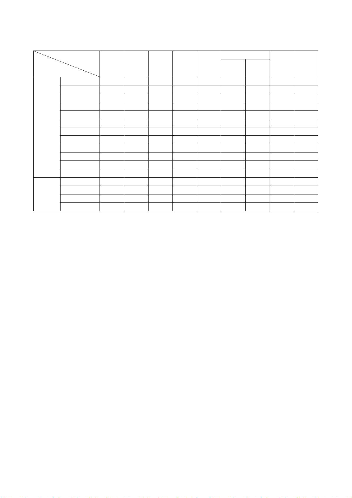
Packing material weight list
Material
Model
SRK20ZS-W 11.5 1.21 0.00 0.33 0.88 0.00 0.00 0.00 0.00
SRK25ZS-W 11.5 1.21 0.00 0.33 0.88 0.00 0.00 0.00 0.00
SRK35ZS-W 11.5 1.21 0.00 0.33 0.88 0.00 0.00 0.00 0.00
SRK50ZS-W 12.0 1.21 0.00 0.33 0.88 0.00 0.00 0.00 0.00
SRK20ZS-WB 11.5 1.21 0.00 0.33 0.88 0.00 0.00 0.00 0.00
Indoor
Outdoor
SRK25ZS-WB 11.5 1.21 0.00 0.33 0.88 0.00 0.00 0.00 0.00
SRK35ZS-WB 11.5 1.21 0.00 0.33 0.88 0.00 0.00 0.00 0.00
SRK50ZS-WB 12.0 1.21 0.00 0.33 0.88 0.00 0.00 0.00 0.00
SRK20ZS-WT 11.5 1.21 0.00 0.33 0.88 0.00 0.00 0.00 0.00
SRK25ZS-WT 11.5 1.21 0.00 0.33 0.88 0.00 0.00 0.00 0.00
SRK35ZS-WT 11.5 1.21 0.00 0.33 0.88 0.00 0.00 0.00 0.00
SRK50ZS-WT 12.0 1.21 0.00 0.33 0.88 0.00 0.00 0.00 0.00
SRC20ZS-W 32.5 2.04 0.00 0.35 1.69 0.00 0.00 0.00 0.00
SRC25ZS-W 32.5 2.04 0.00 0.35 1.69 0.00 0.00 0.00 0.00
SRC35ZS-W 36.0 2.04 0.00 0.35 1.69 0.00 0.00 0.00 0.00
SRC50ZS-W 38.0 2.13 0.00 0.35 1.78 0.00 0.00 0.00 0.00
Gross
Weight
Packing
Parts
weight
(Total)
Glass Plastic
Paper
and
board
Metal
Aluminium
Steel
Unit: kg
Wood Other
-
15
-
Page 17
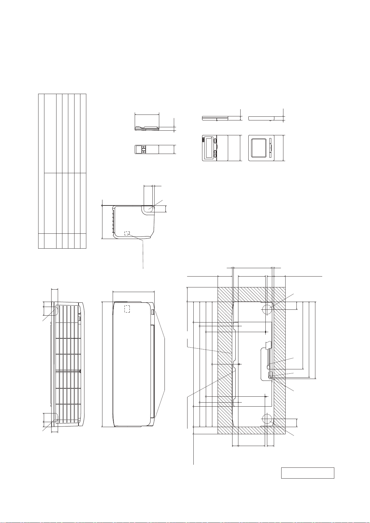
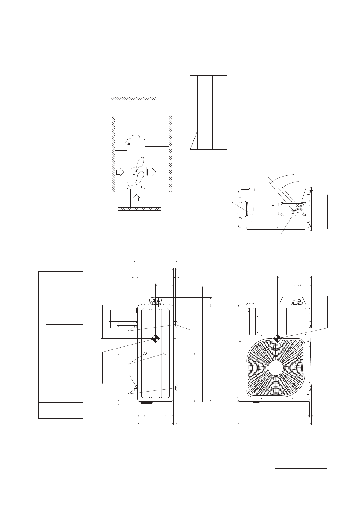
Space for installation and service when viewing from the front
2. EXTERIOR DIMENSIONS
(1) Indoor units
Models SRK20ZS-W, 25ZS-W, 35ZS-W, 50ZS-W
SRK20ZS-WB, 25ZS-WB, 35ZS-WB, 50ZS-WB
SRK20ZS-WT, 25ZS-WT, 35ZS-WT, 50ZS-WT
'18 • SRK-T-250
SRK20, 25, 35 φ9.52(3/8")(Flare)
Content
Gas piping
A
Symbol
SRK50 φ12.7(1/2")(Flare)
Liquid piping
B
45
VP16
φ6.35(1/4")(Flare)
(φ65)
(φ65)
230 3
Hole on wall for right rear piping
Hole on wall for left rear piping
Outlet for piping(on both side)
Drain hose
F
ECD
167
60 24
Wireless remote control
6013
F
45
Terminal block
290
(Option)
Wired remote control
9
(Service space)
100
19
□120
268
190
Unit:mm
□120 19
Notes(1)The model name label is attached
on the right side of the unit.
(2)To connect the wired remote control,
the interface kit(SC-BIKN2-E)is required.
13
47
80 100
(Service space)
C
60 3535 60
170
210
(Service space)
528
Unit
SRK 20,25,35 :469
537
SRK 50 :475
A
870
(Refer to the top view)
Outlet for downward piping
45
F F
530
450
585
435 435
210
170
142.5 142.5
Installation board
50
(Service space)
B
55 55
D E
185
43
47
RLF000Z103
-
16
-
Page 18
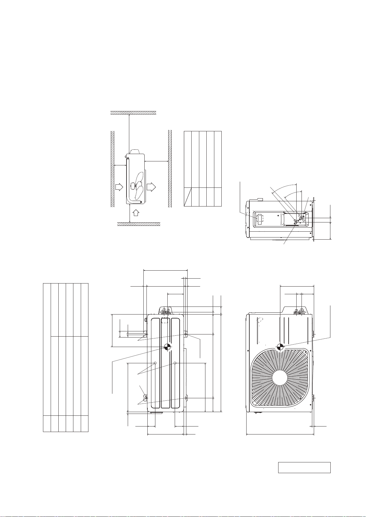
(2) Outdoor units
Models SRC20ZS-W, 25ZS-W, 35ZS-W
L4
Service
space
( )
'18 • SRK-T-250
Unit:mm
L3
Inlet
L2
protrude more than 15mm.
strong winds, place the unit such that the direction of air from the
(2) The unit must be fixed with anchor bolts. An anchor bolt must not
(1) The unit must not be surrounded by walls on the four sides.
Notes
(Flare)
φ9.52(3/8")
outlet gets perpendicular to the wind direction.
(3) If the unit is installed in the location where there is a possibility of
(Flare)
φ6.35(1/4")
(4) Leave 200mm or more space above the unit.
(5) The wall height on the outlet side should be 1200mm or less.
(6) The model name label is attached on the right side of the unit.
φ20×2 places
M10-12×4 places
260
50.6
12
L1
Outlet
Inlet
351.6
E
100 or more
280 or more
Installation space
L2L3L4
L1
16.4
14.8 312.5 24.3
130
80 or more
250 or more
17.9
Terminal block
C
40°
B
40°
A
138.4 33.5
270
97.7 42.5
Center of gravity
Content
A Service valve connection(gas side)
Symbol
Service valve connection(liquid side)
Drain discharge hole
B
E Anchor bolt hole
D
C Pipe/cable draw-out hole
D
Center of gravity
390.6
E
14.6
2-R
63.4
290540 20
-
-
17
2-12×16
Slot hole
390.6
69.4
780 61.9
111.6 510 158.4
15.8
RCV000Z036
Page 19
Model SRC50ZS-W
'18 • SRK-T-250
L4
Service
space
( )
L3
Inlet
L2
(1) The unit must not be surrounded by walls on the four sides.
(2) The unit must be fixed with anchor bolts. An anchor bolt must not
protrude more than 15mm.
(3) If the unit is installed in the location where there is a possibility of
strong winds, place the unit such that the direction of air from the
outlet gets perpendicular to the wind direction.
(4) Leave 200mm or more space above the unit.
(5) The wall height on the outlet side should be 1200mm or less.
Notes
(6) The model name label is attached on the right side of the unit.
L1
Outlet
Inlet
351.6
145
80 or more
100 or more
280 or more
Installation space
L2L3L4
L1
16.4
14.8 312.5 24.3
17.9
250 or more
Terminal block
C
40°
Unit:mm
40°
A
138.4 33.5
B
275
97.7 42.5
φ12.7(1/2")(Flare)
Content
A Service valve connection(gas side)
Symbol
φ20×2 places
M10-12×4 places
φ6.35(1/4")(Flare)
Drain discharge hole
Service valve connection(liquid side)
E Anchor bolt hole
D
B
C Pipe/cable draw-out hole
50.6
12
270
EDE
Center of gravity
390.6
14.6
2-R
63.4
29020
-
18
2-12×16
Slot hole
390.6
69.4
-
Center of gravity
780 61.9
111.6 510 158.4
15.8
595
RCV000Z037
Page 20
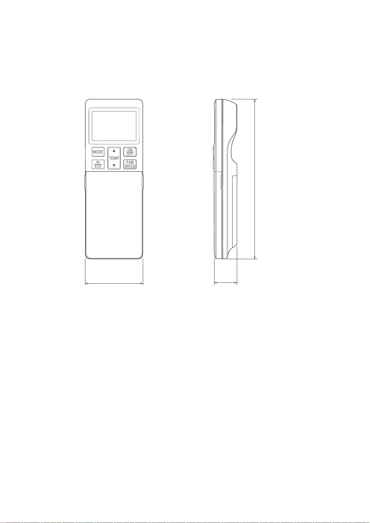
(3) Remote control
(a) Wireless remote control
'18 • SRK-T-250
Unit : mm
167
60
24
-
19
-
Page 21
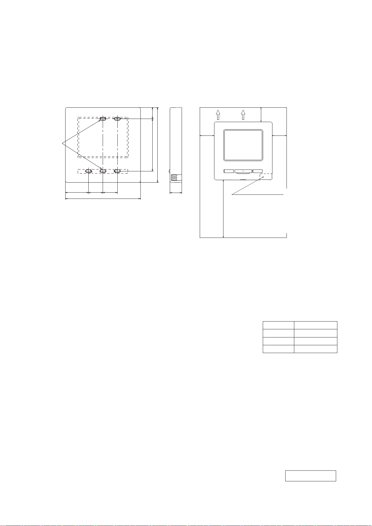
(b) Wired remote control (Option parts)
Interface kit (SC-BIKN2-E) is required to use the wired remote control.
Model RC-EX3A
'18 • SRK-T-250
Fixing holes
固定穴
Dimensions (Viewed from front)
37 23 23
37 23 23
120
120
18.3
18.383.5
120
83.5
120
19
19
Installation space
配線
Wiring
30mm
30mm
120mm
120mm
● Do not install the remote control at following places.
(1) It could cause break-down or deformation of remote control.
・Where it is exposed to direct sunlight
・Where the ambient temperature becomes 0 °C or below, or 40 °C or above
・Where the surface is not flat
・Where the strength of installation area is insufficient
(2) Moisture may be attached to internal parts of the remote control, resulting in a display failure.
・Place with high humidity where condensation occurs on the remote control
・Where the remote control gets wet
(3) Accurate room temperature may not be detected using the temperature sensor of the remote
control.
・Where the average room temperature cannot be detected
・Place near the equipment to generate heat
・Place affected by outside air in opening/closing the door
・Place exposed to direct sunlight or wind from air-conditioner
・Where the difference between wall and room temperature is large
(4) When you are using the automatic grille up and down panel in the IU, you may not be able to
confirm the up and down motion.
・Where the IU cannot be visually confirmed
30mm
30mm
30mm
30mm
R/C temperature sensor
Secure minimum spaces for disassembling the case.
Upper left and Upper right sides
……30mm or more
Bottom side…120mm or more
If using L-shaped screwdriver, 50mm or more is
available.
2
R/C cable:0.3mm
When the cable length is longer than 100 m,
the max size for wires used in the R/C case
is 0.5 mm2 . Connect them to wires of larger
size near the outside of R/C. When wires are
connected, take measures to prevent water,
etc. from entering inside.
200 m 0.5 mm
≦
300m 0.75 mm
≦
400m 1.25 mm
≦
600m 2.0 mm
≦
x2 cores
2
x 2 cores
2
x 2 cores
2
x 2 cores
2
x 2 cores
● When installing the unit at a hospital, telecommunication facility, etc., take
measures to suppress electric noises.
It could cause malfunction or break-down due to hazardous effects on the inverter, private power
generator, high frequency medical equipment, radio communication equipment, etc.
The influences transmitted from the remote control to medical or communication equipment could
disrupt medical activities, video broadcasting or cause noise interference.
-
-
20
Adapted RoHS directive
PJZ000Z333
Page 22

'18 • SRK-T-250
Wiring outlet
Model RC-E5
Exposed mounting
0.3mm2×2 cores
In case of pulling out
from upper left
L C D
48
In case of pulling out
from center
TEMP ON/OFF
ڧ120
Pearl whiteExterior appearance
(Munsell color) (N8.5) near equivalent
Embedded mounting
Cut off the upper thin part of remote control lower case with a nipper or knife,
and grind burrs with a file etc.
X, Y Terminal block
Attach M3 screw
with washer
The peeling-off length of sheath
Pulling out from upper left
Remote control installation dimensions
In case of pulling out
from upper left
Upper
Board
XY
Lower
In case of pulling out from
upper left
X wiring : 215mm
Y wiring : 195mm
In case of pulling out
from center
Upper part
Lower case
Lower part
Sheath
Upper cace
Wiring
Pulling out from center
X wiring : 170mm
Y wiring : 190mm
Upper
In case of pulling out from center
Sheath
Board
YX
Lower
Wiring
The peeling-off length
of sheath
Upper cace
Wall surface
Wiring
Electrical box
䠄Not included䠅
Remote
control
outline
83.5
Wiring oulet
12×7 Slot hole
42
120
46
23
44
11.5 11
9.5×5 Slot hole 䠄4 places䠅
Tighten the screws after
cutting off the thin part of
screw mounting part.
120
45
Installation hole
䠄1䠅 Installation screw for remote control
19
M4 screw (2 pieces)
Wiring specifications
(1) If the prolongation is over 100m, change to the size below.
But, wiring in the remote control case should be under 0.5mm
the case according to wire connecting. Waterproof treatment is necessary at the wire connecting
section. Be careful about contact failure.
2
. Change the wire size outside of
Unit:mm
Length Wiring thickness
100 to 200m
Under 300m
Under 400m
Under 600m
0.5mm
0.75mm
1.25mm
2.0mm
2
×2 cores
2
×2 cores
2
×2 cores
2
×2 cores
-
21
PJZ000Z295
-
Page 23
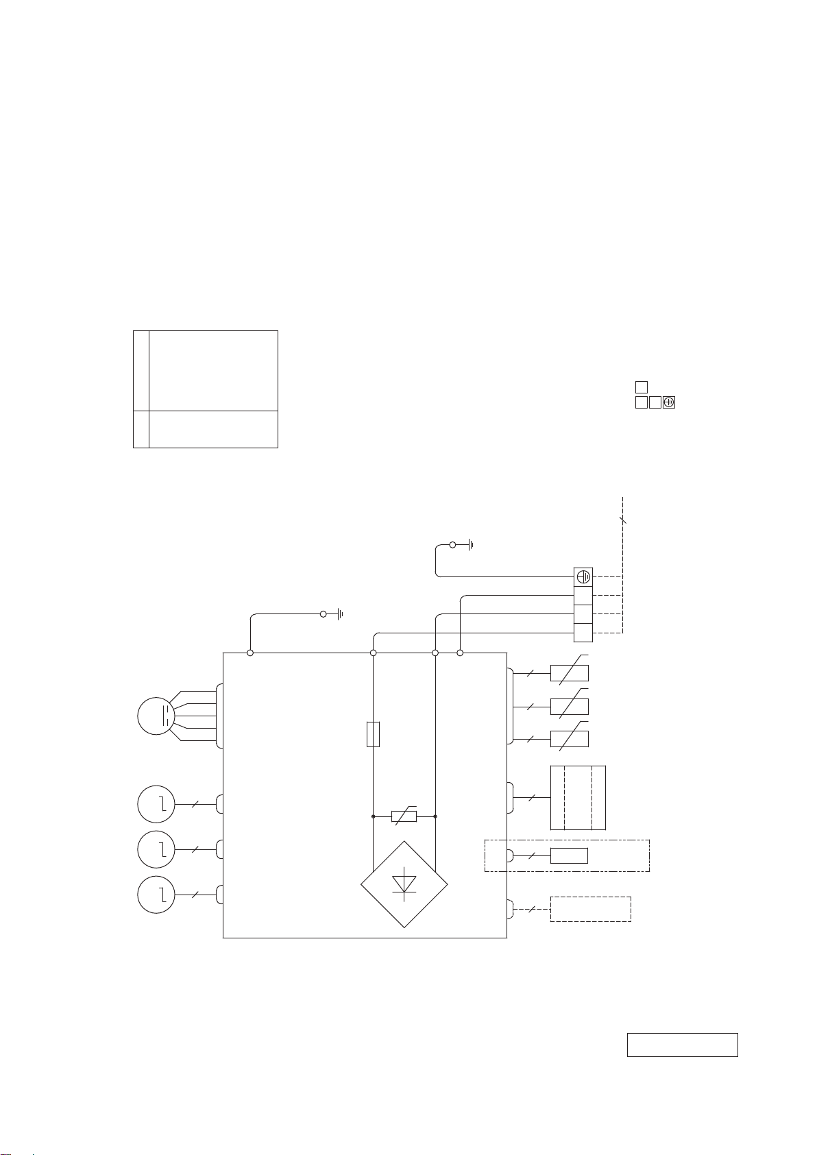
3. ELECTRICAL WIRING
(1) Indoor units
Models SRK20ZS-W, 25ZS-W, 35ZS-W, 50ZS-W
SRK20ZS-WB, 25ZS-WB, 35ZS-WB, 50ZS-WB
SRK20ZS-WT, 25ZS-WT, 35ZS-WT, 50ZS-WT
'18 • SRK-T-250
DescriptionItem
ConnectorCNE
CNF
CNG
CNM
CNS
CNU
CNX
CNY
Power source
1 Phase
220-240V 50Hz
HEAT
EXCHANGER
YELLOW/GREEN
HEAT
EXCHANGER
G
BLUE
YELLOW
4
FAN
MOTOR
WHITE
BLACK
RED
CNU
1 3 65
L
FUSE
F 3.15A L 250V
J
S/N
2 2
CNG
2
BLOCK
TERMINAL
YELLOW/GREEN
3
RED
WHITE
2/N
1
BLACK
t
o
t
o
t
o
2
3
1
220V 60Hz
POWER CABLE
SIGNAL WIRE
EARTH WIRE
TO OUTDOOR UNIT
4
[ ]
SENSOR
ROOM TEMP.
SENSOR 2
HEAT EXCHANGER
SENSOR 1
HEAT EXCHANGER
FLAP
MOTOR
LEFT
MOTOR
LOUVER
RIGHT
MOTOR
LOUVER
M
M M M
VARISTOR
~
U
R-AMP
DISPLAY
WIRELESS
BACK-UP SW
SENSOR
HUMIDITY
※
INTERFACE KIT
ONLY
※SRK35,50ZS-W
~
2 6
CNF CNE
5
CNS
5
CNM
CNX
5 5
CNY
BOARD
CIRCUIT
PRINTED
DIODE
STACK
RWA000Z416
-
-
22
Page 24
Switchgear or circuit breaker capacity should be chosen according to national or regional electricity
The power cable specifications are based on the assumption that a metal or plastic conduit is used
with no more than three cables contained in a conduit and a voltage drop is 2
falling outside of these conditions, please follow the national or regional electricity regulations.
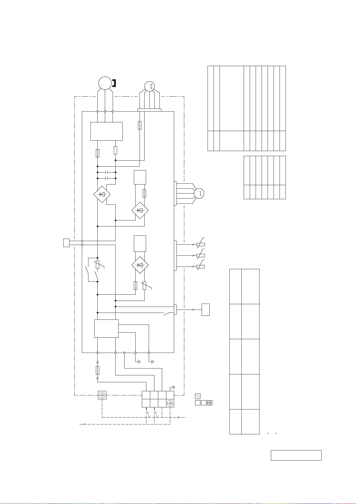
(2) Outdoor units
Models SRC20ZS-W, 25ZS-W, 35ZS-W
PCB ASSY PCB1
POWER
TRANSISTOR
F2
(RD)
U
UP
MS
3~
(WH)
V
V
250V 20A
'18 • SRK-T-250
CM
(BK)
W
W
N
F3
T 1A L 250V
M
FMo
CNFAN
(WH)
Item Description
Meaning of marks
CN20S Connector
20S 4-way valve(coil)
CNFAN
CNEEV
L Reactor
FMo Fan motor
EEV Electric expansion valve(coil)
CM Compressor motor
CNTH
TH4 Discharge pipe temp. sensor
TH3 Outdoor air temp. sensor
TH2 Heat exchanger sensor
+
+
+
-
DIODE
STACK2
~
~
L
T1 T2
(YE) (OR)
t゜
NOISE
FILTER
DIODE
STACK1
DIODE
STACK4
PAM
+
~
SWITCHING
+
~
F1
F 3.15A L 250V
CIRCUIT
F4
POWER
CIRCUIT
250V 10A
-
~
-
~
t゜
(RD)
(WH)
(BK)
CNTH CNEEV
CN20S
Yellow/Green
M
EEV
t゜
22
2 2
TH4TH2 TH3
t゜
t゜
20S
Mark Color
BK Black
Color marks
Connecting cable
wire size x number*
(m)
Power cable length
RD Red
2
WH White
OR Orange
YE Yellow
YG
%. For an installation
220V 60Hz
Power source
1 Phase
220-240V 50Hz
250V 15A
S.IN
(WH)
G1
(YG)
TB1
BLOCK
TERMINAL
G2
(YG)
(BK)
L 1
(YG)
3
N 2
4
N
2
3
1
POWER CABLE
SIGNAL WIRE
EARTH WIRE
TO INDOOR UNIT
[ ]
Power cable, indoor-outdoor connecting wires
wire size x number*(A)
MAX running current Power cable
Model name
SRC20ZS-W
2
9
SRC25ZS-W 2.0mm x 3 22 1.5mm x 4
SRC35ZS-W
The wire numbers include earth wire(Yellow/Green).
*
regulations.
C-2
(RD)
R.IN
(BK)
F7
3
RWC000Z315
-
-
23
Page 25

Switchgear or circuit breaker capacity should be chosen according to national or regional electricity
The power cable specifications are based on the assumption that a metal or plastic conduit is used
with no more than three cables contained in a conduit and a voltage drop is 2
falling outside of these conditions, please follow the national or regional electricity regulations.
Model SRC50ZS-W
POWER
TRANSISTOR
'18 • SRK-T-250
CM
MS
3~
(BK)
(WH)
(RD)
U
V
W
UP
V
W
N
+
++
F3
T 1A L 250V
M
FMo
CNFAN
(WH)
Item Description
20S 4-way valve(coil)
Meaning of marks
CNFAN
CNEEV
CN20S Connector
FMo Fan motor
EEV Electric expansion valve(coil)
CM Compressor motor
CNTH
TH3 Discharge pipe temp. sensor
TH2 Outdoor air temp. sensor
TH1 Heat exchanger sensor
L1,2 Reactor
Yellow/Green
T2
(YE)
(YE)
T1
DIODE
STACK1
PCB ASSY PCB1
L1
F4
+
~
R.IN
(BK)
T12
(BL)
L2
(BL)
T11
NOISE
FILTER
S.IN
(WH)
250V 20A
-
~
PAM
CIRCUIT
PAM
CIRCUIT
(WH)
M
EEV
Mark Color
BK Black
Color marks
BL Blue
RD Red
WH White
YE Yellow
YG
t゜
POWER
CIRCUIT
SWITCHING
(RD)
(BK)
CNTH CNEEV
CN20S
2 2 22
+
F8
DIODE
STACK2
250V 20A
C-2
(RD)
-
~
~
F1
F 3.15A L 250V
G1
G2
(YG)
(YG)
TH3TH2TH1
t゜
t゜
2
Connecting cable
20S
wire size x number*
%. For an installation
(m)
Power cable length
2
2.0mm x 3 14 1.5mm x 414.5
wire size x number*(A)
220V 60Hz
Power source
1 Phase
220-240V 50Hz
(BK)
L 1
TB1
BLOCK
TERMINAL
3
(YG)
3
N 2
4
N
2
3
1
POWER CABLE
SIGNAL WIRE
EARTH WIRE
TO INDOOR UNIT
[ ]
MAX running current Power cable
Model name
SRC50ZS-W
Power cable, indoor-outdoor connecting wires
The wire numbers include earth wire(Yellow/Green).
*
regulations.
RWC000Z316
-
-
24
Page 26

4. NOISE LEVEL
(1) Sound power level
Model SRK20ZS-W, -WB, -WT
'18 • SRK-T-250
(Indoor unit)
Model SRK20ZS-W,WB,WT
oise Cooling 48 dB(A)
N
Level Heating 50 dB(A)
70
60
50
40
30
Sound power level (dB)
20
10
63 125 250 500 1000 2000 4000 8000
Condition
M
× Cooling ○ Heating
Mid octave band frequency (Hz)
ODE
ISO5151 T1/H1
Rated capacity value
(Outdoor unit)
Model SRC20ZS-W
oise Cooling 56 dB(A)
N
L
evel Heating 56 dB(A)
70
60
50
40
30
Sound power level (dB)
20
10
63 125 250 500 1000 2000 4000 8000
× Cooling ○ Heating
Mid octave band frequency (Hz)
-
25
-
Page 27

Model SRK25ZS-W, -WB, -WT
'18 • SRK-T-250
(Indoor unit)
Model SRK25ZS-W,WB,WT
oise Cooling 50 dB(A)
N
Level Heating 53 dB(A)
70
60
50
40
30
Sound power level (dB)
20
10
63 125 250 500 1000 2000 4000 8000
Condition
M
× Cooling ○ Heating
Mid octave band frequency (Hz)
ODE
ISO5151 T1/H1
Rated capacity value
(Outdoor unit)
Model SRC25ZS-W
oise Cooling 56 dB(A)
N
L
evel Heating 58 dB(A)
70
60
50
40
30
Sound power level (dB)
20
10
63 125 250 500 1000 2000 4000 8000
× Cooling ○ Heating
Mid octave band frequency (Hz)
-
26
-
Page 28

Model SRK35ZS-W, -WB, -WT
'18 • SRK-T-250
(Indoor unit)
Model SRK35ZS-W,WB,WT
oise Cooling 54 dB(A)
N
Level Heating 56 dB(A)
70
60
50
40
30
Sound power level (dB)
20
10
63 125 250 500 1000 2000 4000 8000
Condition
M
× Cooling ○ Heating
Mid octave band frequency (Hz)
ODE
ISO5151 T1/H1
Rated capacity value
(Outdoor unit)
Model SRC35ZS-W
oise Cooling 61 dB(A)
N
L
evel Heating 61 dB(A)
70
60
50
40
30
Sound power level (dB)
20
10
63 125 250 500 1000 2000 4000 8000
× Cooling ○ Heating
Mid octave band frequency (Hz)
-
27
-
Page 29

Model SRK50ZS-W, -WB, -WT
'18 • SRK-T-250
(Indoor unit)
Model SRK50ZS-W,WB,WT
oise Cooling 59 dB(A)
N
Level Heating 60 dB(A)
70
60
50
40
30
Sound power level (dB)
20
10
63 125 250 500 1000 2000 4000 8000
Condition
M
× Cooling ○ Heating
Mid octave band frequency (Hz)
ODE
ISO5151 T1/H1
Rated capacity value
(Outdoor unit)
Model SRC50ZS-W
oise Cooling 61 dB(A)
N
L
evel Heating 63 dB(A)
70
60
50
40
30
Sound power level (dB)
20
10
63 125 250 500 1000 2000 4000 8000
× Cooling ○ Heating
Mid octave band frequency (Hz)
-
28
-
Page 30

(2) Sound pressure level
(a) Rated capacity value
Model SRK20ZS-W, -WB, -WT
(Indoor unit)
Model SRK20ZS-W,WB,WT
oise Cooling 34 dB(A)
N
Level Heating 36 dB(A)
70
Condition
ODE
M
Rated capacity value
Mike position
1m
Unit
× Cooling ○ Heating
N70
'18 • SRK-T-250
ISO5151 T1/H1
0.8m
Mike position
(Center & low points)
70
60
Pa)
-5
50
40
(Standard 2x10
30
Sound pressure level (dB)
20
10
63 125 250 500 1000 2000 4000 8000
(Outdoor unit)
Model SRC20ZS-W
oise Cooling 45 dB(A)
N
L
evel Heating 45 dB(A)
70
Mid octave band frequency (Hz)
Mike position: at highest noise level in position as mentioned below
Distance from front side 1m
× Cooling ○ Heating
N60
N50
N40
N30
N20
N70
60
50
40
30
20
10
70
60
Pa)
-5
50
40
(Standard 2x10
30
Sound pressure level (dB)
20
10
63 125 250 500 1000 2000 4000 8000
Mid octave band frequency (Hz)
-
-
29
N60
N50
N40
N30
N20
60
50
40
30
20
10
Page 31

Model SRK25ZS-W, -WB, -WT
(Indoor unit)
Model SRK25ZS-W,WB,WT
oise Cooling 36 dB(A)
N
Level Heating 39 dB(A)
70
Condition
ODE
M
Rated capacity value
Mike position
1m
Unit
× Cooling ○ Heating
N
70
'18 • SRK-T-250
ISO5151 T1/H1
0.8m
Mike position
(Center & low points)
70
60
Pa)
-5
50
40
(Standard 2x10
30
Sound pressure level (dB)
20
10
63 125 250 500 1000 2000 4000 8000
(Outdoor unit)
Model SRC25ZS-W
oise Cooling 46 dB(A)
N
L
evel Heating 46 dB(A)
70
Mid octave band frequency (Hz)
Mike position: at highest noise level in position as mentioned below
Distance from front side 1m
× Cooling ○ Heating
N
N50
N
N
N
N
60
70
40
30
20
60
50
40
30
20
10
70
60
Pa)
-5
50
40
(Standard 2x10
30
Sound pressure level (dB)
20
10
63 125 250 500 1000 2000 4000 8000
Mid octave band frequency (Hz)
-
-
30
N
N50
N
N
N
60
40
30
20
60
50
40
30
20
10
Page 32

Model SRK35ZS-W, -WB, -WT
(Indoor unit)
Model SRK35ZS-W,WB,WT
oise Cooling 40 dB(A)
N
Level Heating 41 dB(A)
70
Condition
ODE
M
Rated capacity value
Mike position
1m
Unit
× Cooling ○ Heating
N70
'18 • SRK-T-250
ISO5151 T1/H1
0.8m
Mike position
(Center & low points)
70
60
Pa)
-5
50
40
(Standard 2x10
30
Sound pressure level (dB)
20
10
63 125 250 500 1000 2000 4000 8000
(Outdoor unit)
Model SRC35ZS-W
oise Cooling 50 dB(A)
N
L
evel Heating 48 dB(A)
70
Mid octave band frequency (Hz)
Mike position: at highest noise level in position as mentioned below
Distance from front side 1m
× Cooling ○ Heating
N60
N50
N40
N30
N20
N70
60
50
40
30
20
10
70
60
Pa)
-5
50
40
(Standard 2x10
30
Sound pressure level (dB)
20
10
63 125 250 500 1000 2000 4000 8000
Mid octave band frequency (Hz)
-
-
31
N60
N50
N40
N30
N20
60
50
40
30
20
10
Page 33

Model SRK50ZS-W, -WB, -WT
(Indoor unit)
Model SRK50ZS-W,WB,WT
oise Cooling 46 dB(A)
N
Level Heating 46 dB(A)
70
Condition
ODE
M
Rated capacity value
Mike position
1m
Unit
× Cooling ○ Heating
N70
'18 • SRK-T-250
ISO5151 T1/H1
0.8m
Mike position
(Center & low points)
70
60
Pa)
-5
50
40
(Standard 2x10
30
Sound pressure level (dB)
20
10
63 125 250 500 1000 2000 4000 8000
(Outdoor unit)
Model SRC50ZS-W
oise Cooling 51 dB(A)
N
L
evel Heating 52 dB(A)
70
Mid octave band frequency (Hz)
Mike position: at highest noise level in position as mentioned below
Distance from front side 1m
× Cooling ○ Heating
N60
N50
N40
N30
N20
N70
60
50
40
30
20
10
70
60
Pa)
-5
50
40
(Standard 2x10
30
Sound pressure level (dB)
20
10
63 125 250 500 1000 2000 4000 8000
Mid octave band frequency (Hz)
-
-
32
N60
N50
N40
N30
N20
60
50
40
30
20
10
Page 34

(b) Each fan speed mode
(Indoor unit)
Model SRK20ZS-W,WB,WT
oise Cooling 34 dB(A)
N
Level Heating 36 dB(A)
70
Condition
ODE
M
Mike position
1m
Unit
× Cooling ○ Heating
N70
'18 • SRK-T-250
ISO5151 T1/H1
Hi
0.8m
Mike position
(Center & low points)
70
60
Pa)
-5
50
40
(Standard 2x10
30
Sound pressure level (dB)
20
10
63 125 250 500 1000 2000 4000 8000
(Indoor unit)
Model SRK20ZS-W,WB,WT
oise Cooling 25 dB(A)
N
Level Heating 29 dB(A)
70
Mid octave band frequency (Hz)
× Cooling ○ Heating
M
ODE
N60
N50
N40
N30
N20
Mike position
1m
Unit
N70
60
50
40
30
20
10
Me
0.8m
Mike position
(Center & low points)
70
60
Pa)
-5
50
40
(Standard 2x10
30
Sound pressure level (dB)
20
10
63 125 250 500 1000 2000 4000 8000
Mid octave band frequency (Hz)
-
-
33
60
N60
50
N50
40
N40
30
N30
20
N20
10
Page 35

'18 • SRK-T-250
(Indoor unit)
Model SRK20ZS-W,WB,WT
oise Cooling 22 dB(A)
N
Level Heating 23 dB(A)
70
60
Pa)
-5
50
40
(Standard 2x10
30
Sound pressure level (dB)
20
10
63 125 250 500 1000 2000 4000 8000
(Indoor unit)
Model SRK20ZS-W,WB,WT
oise Cooling 19 dB(A)
N
evel Heating 19 dB(A)
L
70
Condition
M
× Cooling ○ Heating
Mid octave band frequency (Hz)
MODE
× Cooling ○ Heating
ODE
Mike position
Mike position
ISO5151 T1/H1
1m
0.8m
Unit
N70
N60
N50
N40
N30
N20
1m
0.8m
Unit
N70
Lo
Mike position
(Center & low points)
70
60
50
40
30
20
10
ULo
Mike position
(Center & low points)
70
60
Pa)
-5
50
40
(Standard 2x10
30
Sound pressure level (dB)
20
10
63 125 250 500 1000 2000 4000 8000
Mid octave band frequency (Hz)
-
-
34
N60
N50
N40
N30
N20
60
50
40
30
20
10
Page 36

ISO5151 T1/H1
(Indoor unit)
Model SRK25ZS-W,WB,WT
oise Cooling 36 dB(A)
N
Level Heating 39 dB(A)
70
Condition
ODE
M
Mike position
1m
Unit
× Cooling ○ Heating
N70
Hi
0.8m
Mike position
(Center & low points)
70
'18 • SRK-T-250
60
Pa)
-5
50
40
(Standard 2x10
30
Sound pressure level (dB)
20
10
63 125 250 500 1000 2000 4000 8000
(Indoor unit)
Model SRK25ZS-W,WB,WT
oise Cooling 28 dB(A)
N
evel Heating 30 dB(A)
L
70
Mid octave band frequency (Hz)
MODE
× Cooling ○ Heating
N60
N50
N40
N30
N20
Mike position
1m
Unit
N70
60
50
40
30
20
10
Me
0.8m
Mike position
(Center & low points)
70
-5
Sound pressure level (dB)
60
Pa)
50
40
(Standard 2x10
30
20
10
63 125 250 500 1000 2000 4000 8000
Mid octave band frequency (Hz)
-
-
35
N60
N50
N40
N30
N20
60
50
40
30
20
10
Page 37

ISO5151 T1/H1
(Indoor unit)
Model SRK25ZS-W,WB,WT
oise Cooling 23 dB(A)
N
Level Heating 24 dB(A)
70
Condition
ODE
M
Mike position
1m
Unit
× Cooling ○ Heating
N70
Lo
0.8m
Mike position
(Center & low points)
70
'18 • SRK-T-250
60
Pa)
-5
50
40
(Standard 2x10
30
Sound pressure level (dB)
20
10
63 125 250 500 1000 2000 4000 8000
(Indoor unit)
Model SRK25ZS-W,WB,WT
oise Cooling 19 dB(A)
N
evel Heating 19 dB(A)
L
70
Mid octave band frequency (Hz)
MODE
× Cooling ○ Heating
N60
N50
N40
N30
N20
Mike position
1m
Unit
N70
60
50
40
30
20
10
ULo
0.8m
Mike position
(Center & low points)
70
-5
Sound pressure level (dB)
60
Pa)
50
40
(Standard 2x10
30
20
10
63 125 250 500 1000 2000 4000 8000
Mid octave band frequency (Hz)
-
-
36
N60
N50
N40
N30
N20
60
50
40
30
20
10
Page 38

'18 • SRK-T-250
(Indoor unit)
Model SRK35ZS-W,WB,WT
oise Cooling 40 dB(A)
N
Level Heating 41 dB(A)
70
60
Pa)
-5
50
40
(Standard 2x10
30
Sound pressure level (dB)
20
Condition
ODE
M
Mike position
1m
Unit
× Cooling ○ Heating
N70
N60
N50
N40
N30
ISO5151 T1/H1
Hi
0.8m
Mike position
(Center & low points)
70
60
50
40
30
20
10
63 125 250 500 1000 2000 4000 8000
(Indoor unit)
Model SRK35ZS-W,WB,WT
oise Cooling 30 dB(A)
N
evel Heating 36 dB(A)
L
70
60
Pa)
-5
50
40
(Standard 2x10
30
Sound pressure level (dB)
Mid octave band frequency (Hz)
MODE
× Cooling ○ Heating
N20
Mike position
1m
Unit
N70
N60
N50
N40
N30
10
Me
0.8m
Mike position
(Center & low points)
70
60
50
40
30
20
10
63 125 250 500 1000 2000 4000 8000
Mid octave band frequency (Hz)
-
-
37
20
N20
10
Page 39

'18 • SRK-T-250
(Indoor unit)
Model SRK35ZS-W,WB,WT
oise Cooling 26 dB(A)
N
Level Heating 25 dB(A)
70
60
Pa)
-5
50
40
(Standard 2x10
30
Sound pressure level (dB)
20
Condition
ODE
M
Mike position
1m
Unit
× Cooling ○ Heating
N70
N60
N50
N40
N30
N20
ISO5151 T1/H1
Lo
0.8m
Mike position
(Center & low points)
70
60
50
40
30
20
10
63 125 250 500 1000 2000 4000 8000
(Indoor unit)
Model SRK35ZS-W,WB,WT
oise Cooling 19 dB(A)
N
Level Heating 19 dB(A)
70
60
Pa)
-5
50
40
(Standard 2x10
30
Sound pressure level (dB)
20
Mid octave band frequency (Hz)
M
× Cooling ○ Heating
ODE
Mike position
Unit
1m
0.8m
N70
N60
N50
N40
N30
N20
10
ULo
Mike position
(Center & low points)
70
60
50
40
30
20
10
63 125 250 500 1000 2000 4000 8000
Mid octave band frequency (Hz)
-
-
38
10
Page 40

'18 • SRK-T-250
(Indoor unit)
Model SRK50ZS-W,WB,WT
oise Cooling 46 dB(A)
N
Level Heating 46 dB(A)
70
60
Pa)
-5
50
40
(Standard 2x10
30
Sound pressure level (dB)
20
Condition
ODE
M
Mike position
1m
Unit
× Cooling ○ Heating
N70
N60
N50
N40
N30
N20
ISO5151 T1/H1
Hi
0.8m
Mike position
(Center & low points)
70
60
50
40
30
20
10
63 125 250 500 1000 2000 4000 8000
(Indoor unit)
Model SRK50ZS-W,WB,WT
oise Cooling 36 dB(A)
N
evel Heating 37 dB(A)
L
70
60
Pa)
-5
50
40
(Standard 2x10
30
Sound pressure level (dB)
Mid octave band frequency (Hz)
MODE
× Cooling ○ Heating
Mike position
1m
Unit
N70
N60
N50
N40
N30
10
Me
0.8m
Mike position
(Center & low points)
70
60
50
40
30
20
10
63 125 250 500 1000 2000 4000 8000
Mid octave band frequency (Hz)
-
-
39
20
N20
10
Page 41

'18 • SRK-T-250
(Indoor unit)
Model SRK50ZS-W,WB,WT
oise Cooling 29 dB(A)
N
Level Heating 31 dB(A)
70
60
Pa)
-5
50
40
(Standard 2x10
30
Sound pressure level (dB)
20
Condition
ODE
M
Mike position
1m
Unit
× Cooling ○ Heating
N70
N60
N50
N40
N30
N20
ISO5151 T1/H1
Lo
0.8m
Mike position
(Center & low points)
70
60
50
40
30
20
10
63 125 250 500 1000 2000 4000 8000
(Indoor unit)
SRK50ZS-W,WB,WT
oise Cooling 22 dB(A)
N
Level Heating 24 dB(A)
70
60
Pa)
50
-5
40
30
(Standard 2x10
Sound pressure level (dB)
20
Mid octave band frequency (Hz)
M
× Cooling ○ Heating
ODE
Mike position
Unit
1m
0.8m
N70
N60
N50
N40
N30
N20
10
ULo
Mike position
(Center & low points)
70
60
50
40
30
20
10
0
63 125 250 500 1000 2000 4000 8000
Mid octave band frequency (Hz)
-
-
40
10
0
Page 42

'18 • SRK-T-250
(Outdoor unit)
Model SRC20ZS-W
oise Cooling 42 dB(A)
N
Level Heating 43 dB(A)
70
60
Pa)
-5
50
40
(Standard 2x10
30
Sound pressure level (dB)
20
10
63 125 250 500 1000 2000 4000 8000
Condition
Mike position: at highest noise level in position as mentioned below
Distance from front side 1m
M
× Cooling ○ Heating
Mid octave band frequency (Hz)
ODE
ISO5151 T1/H1
Silent
70
N70
60
N60
50
N50
40
N40
30
N30
20
N20
10
(Outdoor unit)
Model SRC25ZS-W
oise Cooling 42 dB(A)
N
Level Heating 43 dB(A)
70
60
Pa)
-5
50
40
(Standard 2x10
30
Sound pressure level (dB)
20
10
63 125 250 500 1000 2000 4000 8000
Mike position: at highest noise level in position as mentioned below
Distance from front side 1m
M
× Cooling ○ Heating
Mid octave band frequency (Hz)
ODE
N70
N60
N50
N40
N30
N20
Silent
70
60
50
40
30
20
10
-
41
-
Page 43

'18 • SRK-T-250
(Outdoor unit)
Model SRC35ZS-W
oise Cooling 45 dB(A)
N
evel Heating 44 dB(A)
L
70
60
Pa)
-5
50
40
(Standard 2x10
30
Sound pressure level (dB)
20
10
63 125 250 500 1000 2000 4000 8000
Condition
Mike position: at highest noise level in position as mentioned below
Distance from front side 1m
MODE
× Cooling ○ Heating
Mid octave band frequency (Hz)
ISO5151 T1/H1
Silent
70
N70
60
N60
50
N50
40
N40
30
N30
20
N20
10
(Outdoor unit)
Model SRC50ZS-W
oise Cooling 43 dB(A)
N
evel Heating 45 dB(A)
L
70
60
Pa)
-5
50
40
(Standard 2x10
30
Sound pressure level (dB)
20
10
63 125 250 500 1000 2000 4000 8000
Mike position: at highest noise level in position as mentioned below
Distance from front side 1m
MODE
× Cooling ○ Heating
Mid octave band frequency (Hz)
N70
N60
N50
N40
N30
N20
Silent
70
60
50
40
30
20
10
-
42
-
Page 44

'09•SRK-DB-087D
Models SRK20ZS-S, 25ZS-S
Model SRK35ZS-S
Humidity
sensor
(HD)
pipe
pipe
4-way valve
4-way valve
5. PIPING SYSTEM
Models SRK20ZS-W, 25ZS-W
SRK20ZS-WB, 25ZS-WB
SRK20ZS-WT, 25ZS-WT
'18 • SRK-T-250
Models SRK35ZS-W
SRK35ZS-WB
SRK35ZS-WT
-
43
-
Page 45

Models SRK50ZS-W
Model SRK50ZM-S
SRK50ZS-WB
Room temp.
sensor
Indoor unit
(Th1)
Humidity
sensor
(HD)
SRK50ZS-WT
Heat
exchanger
sensor
(Th3)
Heat
exchanger
Heat
exchanger
sensor
(Th2)
Flare
connection
Gas
pipe
(φ12.7)
Liquid
pipe
(φ6.35)
Outdoor unit
Service valve
Gas
)
(
Check joint
4-way valve
Service valve
(Liquid)
Muffler
Receiver
Discharge pipe
temp. sensor
(TH3)
Compressor
Capillary tube
Electronic
expansion valve
(EEV)
Cooling cycle
Heating cycle
Capillary tube
'18 • SRK-T-250
Outdoor air
temp. sensor
(TH2)
Heat
exchanger
Heat
exchanger
sensor
(TH1)
Flare connection
Strainer
Muffler
-
44
-
Page 46

Heating operation
Indoor air DB
temperature
6. RANGE OF USAGE & LIMITATIONS
Heating operation
RANGE OF USAGE & LIMITATIONS
Model
SRK20,25,35ZS-W
SRK20,25,35ZS-WB
SRK20,25,35ZS-WT
Item
Indoor return air temperature
(Upper, lower limits)
Outdoor air temperature
(Upper, lower limits)
Cooling operation : Approximately 18 to 32℃ D.B.
Heating operation : Approximately 10 to 30℃ D.B.
(Refer to the selection chart)
Cooling operation : Approximately -15 to 46℃ D.B.
Heating operation : Approximately -15 to 24℃ D.B.
(Refer to the selection chart)
'18 • SRK-T-250
SRK50ZS-W
SRK50ZS-WB
SRK50ZS-WT
Refrigerant line (one way) length
Vertical height difference between
outdoor unit and indoor unit
Max. 20m Max. 25m
Max. 10m
(Outdoor unit is higher)
Max. 10m
(Outdoor unit is lower)
Max. 15m
(Outdoor unit is higher)
Max. 15m
(Outdoor unit is lower)
Power source voltage Rating ±10%
Voltage at starting Min. 85% of rating
Frequency of ON-OFF cycle
Max. 4 times/h
(Inching prevention 10 minutes)
Max. 7 times/h
(Inching prevention 5 minutes)
ON and OFF interval Min. 3 minutes
Selection chart
Correct the cooling and heating capacity in accordance with the conditions as follows. The net cooling and heating capacity can be
obtained in the following way.
Net capacity = Capacity shown on specification × Correction factors as follows.
(1) Coefficient of cooling and heating capacity in relation to temperatures
1.3
&
Coefficient of cooling
Cooling operation
1.3
1.2
1.2
&
1.1
1.1
1.0
1.0
0.9
0.9
0.8
0.8
heating capacity in
relation to temperature
heating capacity in
relation to temperature
Coefficient of cooling
0.7
0.7
0.6
0.6
46
46
40
40
35
35
30
°C DB
30
25
temperature
25
20
Outdoor air DB
20
°C DB
0
temperature
0
-5
Outdoor air DB
-5
-10
Cooling operation
-15
-10
-15
27
25
30
20
25
15
°C DB
20
10
15
°C DB
temperature
10
-15 -10 -5 0 5 10 15
Indoor air DB
-15 -10 -5 0 5 10 15
Cooling
Cooling
Indoor air WB temperature °C WB
Indoor air WB temperature °C WB
Outdoor air WB temperature °C WB
Outdoor air WB temperature °C WB
Heating
Heating
Applicable range
Applicable range
Depends on installed situation
Depends on installed situation
2220181614
.
ISO-T1 Standard Condition
ISO-T1 Standard condition
ISO-T1 Standard Condition
ISO-H1 Standard condition
2220181614
26
26
24
24
-
45
-
Page 47

'18 • SRK-T-250
'09•SRK-DB-087D
with the piping length of 15m, indoor wet-bulb temperature at 19.0˚C
(2) Correction of cooling and heating capacity in relation to one way length of refrigerant piping
Piping length [m]
Cooling
Heating
(3) Correction relative to frosting on outdoor heat exchanger during heating
Air inlet temperature of
outdoor unit in °C WB
Adjustment coefficient
How to obtain the cooling and heating capacity
Example : The net cooling capacity of the model SRK35ZS-W
and outdoor dry-bulb temperature 35˚C is
Net cooling capacity =
7
1.0
1.0
-15
0.95 0.95 0.94 0.93 0.91 0.88 0.86 0.87 0.92 1.00
SRK35ZS-W
10
0.99
1.0
-10 -9 -7 -5 -3 -1 13
15
0.975
1.0
20
0.965
1.0
25
0.95
1.0
5 or more
-
46
-
Page 48

7. CAPACITY TABLES
Models SRK20ZS-W, -WB, -WT
Air flow
Hi
9.3
3
/min)
(m
Outdoor
temperature
21˚CDB 23˚CDB 26˚CDB 27˚CDB 28˚CDB 31˚CDB 33˚CDB
air
14˚CWB 16˚CWB 18˚CWB 19˚CWB 20˚CWB 22˚CWB 24˚CWB
TC SHC TC SHC TC SHC TC SHC TC SHC TC SHC TC SHC
10 2.25 2.11 2.36 2.08 2.45 2.19 2.49 2.17 2.53 2.15 2.60 2.25 2.67 2.20
12 2.21 2.09 2.32 2.06 2.41 2.18 2.45 2.16 2.50 2.14 2.58 2.24 2.65 2.19
14 2.17 2.06 2.28 2.04 2.38 2.17 2.42 2.15 2.47 2.12 2.55 2.23 2.62 2.18
16 2.13 2.02 2.24 2.02 2.34 2.15 2.39 2.13 2.43 2.11 2.52 2.22 2.59 2.18
18 2.08 1.98 2.19 2.01 2.30 2.14 2.35 2.12 2.40 2.10 2.49 2.21 2.56 2.17
20 2.04 1.94 2.15 1.99 2.26 2.12 2.31 2.10 2.36 2.08 2.45 2.20 2.53 2.16
22 1.99 1.89 2.10 1.97 2.22 2.10 2.28 2.09 2.32 2.07 2.42 2.19 2.50 2.14
24 1.94 1.85 2.05 1.95 2.18 2.07 2.24 2.08 2.28 2.06 2.38 2.18 2.47 2.14
26 1.90 1.80 2.01 1.91 2.14 2.03 2.20 2.06 2.24 2.04 2.35 2.17 2.43 2.13
28 1.85 1.75 1.96 1.86 2.09 1.99 2.15 2.05 2.20 2.03 2.31 2.15 2.40 2.12
30 1.79 1.70 1.90 1.81 2.05 1.94 2.11 2.01 2.16 2.01 2.27 2.14 2.36 2.09
32 1.74 1.65 1.85 1.76 2.00 1.90 2.07 1.96 2.12 2.00 2.23 2.12 2.32 2.08
34 1.69 1.60 1.80 1.71 1.95 1.85 2.02 1.92 2.07 1.97 2.19 2.08 2.28 2.07
35 1.66 1.58 1.77 1.68 1.93 1.83 2.00 1.90 2.05 1.94 2.17 2.06 2.26 2.06
36 1.63 1.55 1.74 1.65 1.90 1.81 1.98 1.88 2.02 1.92 2.15 2.04 2.24 2.05
38 1.58 1.50 1.68 1.60 1.85 1.76 1.93 1.83 1.98 1.88 2.11 2.00 2.20 2.04
39 1.55 1.47 1.66 1.57 1.83 1.74 1.91 1.81 1.95 1.85 2.08 1.98 2.18 2.04
Indoor air temperature
Cooling mode
(kW)
Air flow
Hi
10.0
3
/min)
(m
'18 • SRK-T-250
Heating mode (HC) (kW)
Outdoor
air
temperature
-15˚CWB 1.66 1.63 1.59 1.55 1.52
-10˚CWB 1.88 1.85 1.82 1.78 1.74
-5˚CWB 2.04 2.01 1.97 1.94 1.91
0˚CWB 2.13 2.10 2.07 2.04 2.01
5˚CWB 2.72 2.69 2.67 2.62 2.58
6˚CWB 2.76 2.73 2.70 2.67 2.63
10˚CWB 2.94 2.91 2.89 2.85 2.82
15˚CWB 3.20 3.17 3.14 3.11 3.08
20˚CWB 3.43 3.41 3.39 3.35 3.32
16˚CDB 18˚CDB 20˚CDB 22˚CDB 24˚CDB
Indoor air temperature
Models SRK25ZS-W, -WB, -WT
Air flow
Hi
9.9
3
/min)
(m
Outdoor
temperature
21˚CDB 23˚CDB 26˚CDB 27˚CDB 28˚CDB 31˚CDB 33˚CDB
air
14˚CWB 16˚CWB 18˚CWB 19˚CWB 20˚CWB 22˚CWB 24˚CWB
TC SHC TC SHC TC SHC TC SHC TC SHC TC SHC TC SHC
10 2.82 2.45 2.95 2.41 3.06 2.54 3.11 2.51 3.16 2.48 3.26 2.59 3.34 2.52
12 2.77 2.43 2.90 2.39 3.01 2.52 3.07 2.49 3.12 2.47 3.22 2.58 3.31 2.51
14 2.71 2.41 2.85 2.37 2.97 2.50 3.03 2.48 3.08 2.45 3.18 2.56 3.28 2.50
16 2.66 2.38 2.80 2.35 2.92 2.49 2.98 2.46 3.04 2.44 3.15 2.55 3.24 2.49
18 2.60 2.36 2.74 2.33 2.88 2.47 2.94 2.45 2.99 2.42 3.11 2.54 3.20 2.48
20 2.55 2.33 2.68 2.30 2.83 2.45 2.89 2.43 2.95 2.40 3.07 2.52 3.17 2.47
22 2.49 2.31 2.63 2.28 2.78 2.42 2.84 2.41 2.90 2.38 3.02 2.51 3.13 2.45
24 2.43 2.28 2.57 2.26 2.72 2.40 2.80 2.39 2.85 2.37 2.98 2.49 3.08 2.44
26 2.37 2.25 2.51 2.23 2.67 2.38 2.74 2.37 2.80 2.35 2.93 2.48 3.04 2.43
28 2.31 2.19 2.44 2.20 2.61 2.36 2.69 2.35 2.75 2.33 2.89 2.46 3.00 2.41
30 2.24 2.13 2.38 2.17 2.56 2.34 2.64 2.33 2.70 2.31 2.84 2.44 2.95 2.40
32 2.18 2.07 2.31 2.15 2.50 2.32 2.58 2.31 2.64 2.29 2.79 2.43 2.90 2.38
34 2.11 2.00 2.25 2.12 2.44 2.29 2.53 2.29 2.59 2.27 2.74 2.41 2.85 2.37
35 2.08 1.97 2.21 2.10 2.41 2.28 2.50 2.28 2.56 2.26 2.71 2.40 2.83 2.36
36 2.04 1.94 2.18 2.07 2.38 2.26 2.47 2.27 2.53 2.25 2.69 2.40 2.80 2.36
38 1.97 1.87 2.11 2.00 2.32 2.20 2.41 2.24 2.47 2.22 2.63 2.38 2.75 2.34
39 1.94 1.84 2.07 1.97 2.28 2.17 2.38 2.23 2.44 2.21 2.61 2.37 2.72 2.33
Models SRK35ZS-W -WB, -WT
Air flow
Hi
11.3
3
(m
/min)
Outdoor
temperature
21˚CDB 23˚CDB 26˚CDB 27˚CDB 28˚CDB 31˚CDB 33˚CDB
air
14˚CWB 16˚CWB 18˚CWB 19˚CWB 20˚CWB 22˚CWB 24˚CWB
TC SHC TC SHC TC SHC TC SHC TC SHC TC SHC TC SHC
10 3.94 3.19 4.13 3.14 4.28 3.27 4.35 3.22 4.43 3.18 4.56 3.29 4.68 3.20
12 3.87 3.15 4.06 3.11 4.22 3.24 4.29 3.20 4.37 3.16 4.51 3.27 4.63 3.18
14 3.80 3.12 3.99 3.07 4.16 3.21 4.24 3.17 4.31 3.14 4.46 3.26 4.59 3.16
16 3.72 3.08 3.91 3.04 4.09 3.18 4.18 3.15 4.25 3.12 4.40 3.24 4.54 3.15
18 3.65 3.04 3.84 3.00 4.03 3.16 4.11 3.13 4.19 3.09 4.35 3.21 4.49 3.13
20 3.57 3.01 3.76 2.97 3.96 3.12 4.05 3.10 4.13 3.06 4.29 3.19 4.43 3.12
22 3.49 2.96 3.68 2.93 3.89 3.10 3.98 3.07 4.06 3.04 4.23 3.17 4.38 3.10
24 3.40 2.93 3.59 2.89 3.81 3.07 3.91 3.05 3.99 3.02 4.17 3.15 4.32 3.08
26 3.32 2.89 3.51 2.86 3.74 3.03 3.84 3.01 3.92 2.98 4.11 3.13 4.26 3.06
28 3.23 2.84 3.42 2.82 3.66 3.00 3.77 2.99 3.85 2.96 4.04 3.11 4.20 3.04
30 3.14 2.80 3.33 2.78 3.58 2.97 3.70 2.96 3.78 2.93 3.98 3.08 4.13 3.02
32 3.05 2.75 3.24 2.74 3.50 2.93 3.62 2.92 3.70 2.90 3.91 3.06 4.06 2.99
34 2.95 2.71 3.14 2.69 3.41 2.90 3.54 2.89 3.62 2.87 3.84 3.03 4.00 2.97
35 2.91 2.69 3.10 2.67 3.37 2.89 3.50 2.88 3.58 2.86 3.80 3.02 3.96 2.96
36 2.86 2.67 3.05 2.65 3.33 2.87 3.46 2.87 3.54 2.84 3.76 3.01 3.92 2.95
38 2.76 2.62 2.95 2.61 3.24 2.83 3.38 2.84 3.46 2.81 3.69 2.98 3.85 2.93
39 2.71 2.57 2.90 2.59 3.20 2.81 3.33 2.81 3.42 2.79 3.65 2.97 3.81 2.92
Indoor air temperature
Cooling mode
Cooling mode
IIndoor air temperature
(kW)
(kW)
Air flow
Hi
11.3
3
/min)
(m
Air flow
Hi
12.3
3
/min)
(m
Heating mode (HC) (kW)
Outdoor
air
temperature
-15˚CWB 1.97 1.93 1.88 1.84 1.80
-10˚CWB 2.23 2.19 2.16 2.10 2.06
-5˚CWB 2.41 2.38 2.33 2.30 2.27
0˚CWB 2.53 2.49 2.45 2.42 2.38
5˚CWB 3.22 3.19 3.17 3.10 3.06
6˚CWB 3.27 3.24 3.20 3.16 3.12
10˚CWB 3.48 3.45 3.42 3.38 3.34
15˚CWB 3.79 3.75 3.73 3.69 3.65
20˚CWB
Outdoor
temperature
-15˚CWB 2.46 2.41 2.35 2.30 2.25
-10˚CWB 2.79 2.74 2.70 2.63 2.58
-5˚CWB 3.02 2.97 2.91 2.88 2.83
0˚CWB 3.16 3.12 3.06 3.02 2.98
5˚CWB 4.03 3.98 3.96 3.88 3.83
6˚CWB 4.09 4.04 4.00 3.95 3.90
10˚CWB 4.35 4.31 4.28 4.22 4.18
15˚CWB 4.73 4.69 4.66 4.61 4.56
20˚CWB 5.09 5.05 5.02 4.96 4.92
16˚CDB 18˚CDB 20˚CDB 22˚CDB 24˚CDB
4.07 4.04 4.02 3.97 3.94
Heating mode (HC) (kW)
air
16˚CDB 18˚CDB 20˚CDB 22˚CDB 24˚CDB
Indoor air temperature
Indoor air temperature
Models SRK50ZS-W, -WB, -WT
Air flow
Hi
12.1
3
/min)
(m
Outdoor
temperature
21˚CDB 23˚CDB 26˚CDB 27˚CDB 28˚CDB 31˚CDB 33˚CDB
air
14˚CWB 16˚CWB 18˚CWB 19˚CWB 20˚CWB 22˚CWB 24˚CWB
TC SHC TC SHC TC SHC TC SHC TC SHC TC SHC TC SHC
10 5.63 4.25 5.90 4.17 6.11 4.29 6.22 4.23 6.32 4.17 6.51 4.28 6.69 4.14
12 5.53 4.19 5.80 4.12 6.03 4.25 6.14 4.19 6.25 4.14 6.44 4.25 6.62 4.12
14 5.43 4.14 5.70 4.07 5.94 4.21 6.05 4.16 6.16 4.10 6.37 4.22 6.55 4.09
16 5.32 4.08 5.59 4.02 5.85 4.17 5.96 4.12 6.08 4.07 6.29 4.19 6.48 4.07
18 5.21 4.02 5.48 3.97 5.75 4.13 5.88 4.08 5.99 4.03 6.21 4.16 6.41 4.04
20 5.10 3.96 5.37 3.92 5.65 4.08 5.78 4.04 5.90 3.99 6.13 4.13 6.33 4.02
22 4.98 3.90 5.25 3.86 5.55 4.04 5.69 4.00 5.80 3.95 6.05 4.10 6.25 3.99
24 4.86 3.84 5.14 3.80 5.45 3.99 5.59 3.96 5.71 3.91 5.96 4.07 6.17 3.96
26 4.74 3.78 5.01 3.74 5.34 3.94 5.49 3.92 5.61 3.87 5.87 4.03 6.08 3.93
28 4.61 3.72 4.89 3.68 5.23 3.89 5.39 3.87 5.50 3.83 5.78 4.00 5.99 3.90
30 4.49 3.66 4.76 3.62 5.11 3.85 5.28 3.83 5.40 3.79 5.68 3.96 5.90 3.86
32 4.35 3.59 4.63 3.56 5.00 3.80 5.17 3.78 5.29 3.75 5.58 3.92 5.81 3.83
34 4.22 3.53 4.49 3.49 4.88 3.74 5.06 3.74 5.18 3.70 5.48 3.88 5.71 3.80
35 4.15 3.48 4.42 3.46 4.82 3.72 5.00 3.71 5.12 3.68 5.43 3.86 5.66 3.78
36 4.08 3.45 4.35 3.43 4.76 3.69 4.94 3.69 5.06 3.66 5.37 3.84 5.61 3.76
38 3.94 3.38 4.21 3.36 4.63 3.64 4.82 3.64 4.94 3.61 5.27 3.81 5.50 3.73
39 3.87 3.35 4.14 3.33 4.57 3.61 4.76 3.62 4.88 3.59 5.21 3.79 5.45 3.71
Indoor air temperature
Cooling mode
-
47
(kW)
Air flow
Hi
1
3.9
3
/min)
(m
Notes(1) These data show average statuses.
Depending on the system control, there may be ranges where the operation
is not conducted continuously.
These data show the case where the operation frequency of a compressor is
fixed.
(2) Capacities are based on the following conditions.
Corresponding refrigerant piping length :5m
Level difference of Zero.
(3) Symbols are as follows.
TC : Total cooling capacity (kW)
SHC : Sensible heat capacity (kW)
HC : Heating capacity (kW)
Heating mode (HC) (kW)
Outdoor
air
temperature
-15˚CWB 3.57 3.49 3.41 3.34 3.26
-10˚CWB 4.04 3.97 3.91 3.81 3.73
-5˚CWB 4.37 4.31 4.22 4.18 4.11
0˚CWB 4.59 4.52 4.44 4.39 4.32
5˚CWB 5.84 5.77 5.74 5.63 5.55
6˚CWB 5.94 5.87 5.80 5.73 5.66
10˚CWB 6.31 6.25 6.21 6.12 6.06
15˚CWB 6.86 6.80 6.76 6.68 6.62
20˚CWB 7.38 7.32 7.28 7.20 7.14
16˚CDB 18˚CDB 20˚CDB 22˚CDB 24˚CDB
Indoor air temperature
-
Page 49

RLF012A100
Model SRK20,25,35,50
R410A REFRIGERANT USED
'18 • SRK-T-250
8. APPLICATION DATA
(1) Installation of indoor unit
-
48
-
Page 50

'18 • SRK-T-250
-
49
-
Page 51

'18 • SRK-T-250
-
50
-
Page 52

'18 • SRK-T-250
-
51
-
Page 53

'18 • SRK-T-250
-
52
-
Page 54

'18 • SRK-T-250
-
53
-
Page 55

'18 • SRK-T-250
-
54
-
Page 56

'18 • SRK-T-250
-
55
-
Page 57

'18 • SRK-T-250
(2) Installation of outdoor unit
RWC012A068
-
56
-
Page 58

'18 • SRK-T-250
-
57
-
Page 59

'18 • SRK-T-250
-
58
-
Page 60

'18 • SRK-T-250
-
59
-
Page 61

(3) Safety precautions in handling air-conditioners with ammable refrigerants
'18 • SRK-T-250
is leaked, together with an external ignition source, there is a
possibility of ignition.
The user’s manual should be read carefully.
• The precautionary items mentioned below are distinguished into two levels,
WARNING
CAUTION
• Strict compliance of the domestic laws must be
observed when disposing the appliance.
• Do not use means to accelerate the defrost operation
process or to clean, other than those recommended
by the manufacturer.
1. General
• That the installation of pipe-work shall be kept to a
minimum.
• That pipe-work shall be protected from physical
damage.
• That compliance with national gas regulations shall
be observed.
• That mechanical connections shall be accessible
for maintenance purposes.
• Keep any required ventilation openings clear of
obstruction.
• Servicing shall be performed only as recommended
by the manufacturer.
2. Unventilated areas
• The appliance shall be stored in a well-ventilated
area where the room size corresponds to the room
3.
• The staff in servicing operations must hold the
4. Information on servicing
4.1 Checks to the area
• Prior to beginning work on systems containing
necessary to ensure that the risk of ignition is
minimised.
• For repair to the refrigerating system, 4.3 to 4.7
shall be completed prior to conducting work on the
system.
4.2 Work procedure
• Work shall be undertaken under a controlled
gas or vapour being present while the work is being
performed.
4.3 General work area
• All maintenance staff and others working in the
local area shall be instructed on the nature of work
being carried out.
•
• The area around the workspace shall be sectioned off.
• Ensure that the conditions within the area have
4.4 Checking for presence of refrigerant
• The area shall be checked with an appropriate
refrigerant detector prior to and during work, to
ensure the technician is aware of potentially toxic or
• Ensure that the leak detection equipment being
used is suitable for use with all applicable
refrigerants, i.e.
non-sparking, adequately sealed or intrinsically
safe.
: Wrong installation would cause serious consequences such as injuries or death.
: Wrong installation might cause serious consequences depending on circumstances.
• The appliance shall be stored in a room without
continuously operating ignition sources (for example:
operating electric heater.
4.5
• If any hot work is to be conducted on the
refrigeration equipment or any associated parts,
available to hand. Have a dry powder or CO
extinguisher adjacent to the charging area.
4.6 No ignition sources
• No person carrying out work in relation to a
refrigeration system which involves exposing any
pipe work shall use any sources of ignition in such
explosion.
• All possible ignition sources, including cigarette
the site of installation, repairing, removing and
disposal, during which refrigerant can possibly be
released to the surrounding space.
• Prior to work taking place, the area around the
equipment is to be surveyed to make sure that
• “No Smoking” signs shall be displayed.
4.7 Ventilated area
• Ensure that the area is in the open or that it is
adequately ventilated before breaking into the
system or conducting any hot work.
• A degree of ventilation shall continue during the
period that the work is carried out.
• The ventilation should safely disperse any released
refrigerant and preferably expel it externally into the
atmosphere.
4.8 Checks to the refrigeration equipment
• Where electrical components are being changed,
• At all times the manufacturer’s maintenance and
service guidelines shall be followed.
• If in doubt consult the manufacturer’s technical
department for assistance.
• The following checks shall be applied to
– the charge size is in accordance with the room
size within which the refrigerant containing parts
are installed;
– the ventilation machinery and outlets are
operating adequately and are not obstructed;
– if an indirect refrigerating circuit is being used,
the secondary circuit shall be checked for the
presence of refrigerant;
– marking to the equipment continues to be visible
and legible. Markings and signs that are illegible
shall be corrected;
– refrigeration pipe or components are installed in
a position where they are unlikely to be exposed
to any substance which may corrode refrigerant
containing components, unless the components
are constructed of materials which are inherently
resistant to being corroded or are suitably
protected against being so corroded.
WARNING
WARNING
CAUTION
WALL TYPE AIR-CONDITIONER
RSA012A061A
R32 REFRIGERANT USED
There is information included in the user’s manual and/or
installation manual.
A service personnel should be handing this equipment with
reference to the installation manual.
and
CAUTION
2
.
• Do not pierce or burn.
• Be aware that refrigerants may not contain an
odour.
• The indoor unit shall be stored in a room that has a
minimum area of 4.0 m
4.9 Checks to electrical devices
• Repair and maintenance to electrical components
shall include initial safety checks and component
inspection procedures.
• If a fault exists that could compromise safety, then
no electrical supply shall be connected to the circuit
until it is satisfactorily dealt with.
• If the fault cannot be corrected immediately but it
is necessary to continue operation, an adequate
temporary solution shall be used.
• This shall be reported to the owner of the
equipment so all parties are advised.
• Initial safety checks shall include:
– that capacitors are discharged: this shall be done
in a safe manner to avoid possibility of sparking;
– that no live electrical components and wiring are
exposed while charging, recovering or purging
the system;
– that there is continuity of earth bonding.
5. Repairs to sealed components
• During repairs to sealed components, all electrical
supplies shall be disconnected from the equipment
being worked upon prior to any removal of sealed
covers, etc.
• If it is absolutely necessary to have an electrical
supply to equipment during servicing, then a
permanently operating form of leak detection shall
be located at the most critical point to warn of a
potentially hazardous situation.
• Particular attention shall be paid to the following to
ensure that by working on electrical components,
the casing is not altered in such a way that the level
of protection is affected.
This shall include damage to cables, excessive
number of connections, terminals not made to
• Ensure that the apparatus is mounted securely.
• Ensure that seals or sealing materials have not
degraded to the point that they no longer serve the
atmospheres.
• Replacement parts shall be in accordance with the
NOTE
The use of silicon sealant can inhibit the effectiveness
of some types of leak detection equipment.
Intrinsically safe components do not have to be
isolated prior to working on them.
2
.
C
-
60
-
Page 62

6. Repair to intrinsically safe components
• Do not apply any permanent inductive or
capacitance loads to the circuit without ensuring
that this will not exceed the permissible voltage and
current permitted for the equipment in use.
• Intrinsically safe components are the only types that
can be worked on while live in the presence of a
• The test apparatus shall be at the correct rating.
•
the manufacturer.
• Other parts may result in the ignition of refrigerant
in the atmosphere from a leak.
7. Cabling
• Check that cabling will not be subject to wear,
corrosion, excessive pressure, vibration, sharp
edges or any other adverse environmental effects.
The check shall also take into account the effects
of aging or continual vibration from sources such as
compressors or fans.
8.
• Under no circumstances shall potential sources of
ignition be used in the searching for or detection of
refrigerant leaks.
• A halide torch (or any other detector using a naked
9. Leak detection methods
• Electronic leak detectors may be used to detect
refrigerants, the sensitivity may not be adequate, or
may need re-calibration. (Detection equipment shall
be calibrated in a refrigerant-free area.)
• Ensure that the detector is not a potential source of
ignition and is suitable for the refrigerant used.
• Leak detection equipment shall be set at a
percentage of the LFL of the refrigerant and shall
be calibrated to the refrigerant employed, and the
appropriate percentage of gas (25 % maximum) is
•
refrigerants but the use of detergents containing
chlorine shall be avoided as the chlorine may
react with the refrigerant and corrode the copper
pipe-work.
•
removed/extinguished.
• If a leakage of refrigerant is found which requires
brazing, all of the refrigerant shall be recovered
from the system, or isolated (by means of shut off
valves) in a part of the system remote from the
leak.
•
oxygen free nitrogen (OFN) shall then be purged
through the system both before and during the
brazing process.
10. Removal and evacuation
• When breaking into the refrigerant circuit to make
repairs – or for any other purpose – conventional
refrigerants it is important that best practice is
• The following procedure shall be adhered to:
– remove refrigerant;
– purge the circuit with inert gas;
– evacuate;
– purge again with inert gas;
– open the circuit by cutting or brazing.
• The refrigerant charge shall be recovered into the
correct recovery cylinders.
•
the unit safe.
This process may need to be repeated several
times.
• Compressed air or oxygen shall not be used for
purging refrigerant systems.
CAUTION
•
the working pressure is achieved, then venting to
This process shall be repeated until no refrigerant
is within the system.
•
shall be vented down to atmospheric pressure to
enable work to take place.
This operation is absolutely vital if brazing
operations on the pipe-work are to take place.
• Ensure that the outlet for the vacuum pump is not
close to any ignition sources and that ventilation is
available.
11. Charging procedures
• In addition to conventional charging procedures, the
following requirements shall be followed.
– Ensure that contamination of different refrigerants
does not occur when using charging equipment.
Hoses or lines shall be as short as possible to
minimise the amount of refrigerant contained in
them.
– Cylinders shall be kept upright.
– Ensure that the refrigeration system is earthed
prior to charging the system with refrigerant.
– Label the system when charging is complete (if
not already).
refrigeration system.
• Prior to recharging the system, it shall be pressuretested with the appropriate purging gas.
• The system shall be leak-tested on completion of
charging but prior to commissioning.
• A follow up leak test shall be carried out prior to
leaving the site.
12. Decommissioning
• Before carrying out this procedure, it is essential
that the technician is completely familiar with the
equipment and all its detail.
• It is recommended good practice that all
refrigerants are recovered safely.
• Prior to the task being carried out, an oil and
refrigerant sample shall be taken in case analysis is
required prior to re-use of reclaimed refrigerant.
• It is essential that electrical power is available
before the task is commenced.
a) Become familiar with the equipment and its
operation.
b) Isolate system electrically.
c) Before attempting the procedure ensure that:
– mechanical handling equipment is available, if
required, for handling refrigerant cylinders;
– all personal protective equipment is available and
being used correctly;
– the recovery process is supervised at all times by
a competent person;
– recovery equipment and cylinders conform to the
appropriate standards.
d) Pump down refrigerant system, if possible.
e) If a vacuum is not possible, make a manifold so
that refrigerant can be removed from various parts
of the system.
f) Make sure that cylinder is situated on the scales
before recovery takes place.
g) Start the recovery machine and operate in
accordance with manufacturer’s instructions.
h)
volume liquid charge).
i) Do not exceed the maximum working pressure of
the cylinder, even temporarily.
j)
and the process completed, make sure that the
cylinders and the equipment are removed from site
promptly and all isolation valves on the equipment
are closed off.
k) Recovered refrigerant shall not be charged into
another refrigeration system unless it has been
cleaned and checked.
'18 • SRK-T-250
13. Labelling
• Equipment shall be labelled stating that it has been
de-commissioned and emptied of refrigerant. The
label shall be dated and signed.
•
ensure that there are labels on the equipment
refrigerant.
14. Recovery
• When removing refrigerant from a system, either for
servicing or decommissioning, it is recommended
good practice that all refrigerants are removed
safely.
• When transferring refrigerant into cylinders, ensure
that only appropriate refrigerant recovery cylinders
are employed.
• Ensure that the correct number of cylinders for
holding the total system charge are available.
• All cylinders to be used are designated for
the recovered refrigerant and labelled for that
refrigerant (i.e. special cylinders for the recovery of
refrigerant).
• Cylinders shall be complete with pressure relief
valve and associated shut-off valves in good
working order.
• Empty recovery cylinders are evacuated and, if
possible, cooled before recovery occurs.
• The recovery equipment shall be in good working
order with a set of instructions concerning the
equipment that is at hand and shall be suitable
for the recovery of all appropriate refrigerants
• In addition, a set of calibrated weighing scales shall
be available and in good working order.
• Hoses shall be complete with leak-free disconnect
couplings and in good condition.
• Before using the recovery machine, check that it
is in satisfactory working order, has been properly
maintained and that any associated electrical
components are sealed to prevent ignition in the
event of a refrigerant release.
Consult manufacturer if in doubt.
• The recovered refrigerant shall be returned to the
refrigerant supplier in the correct recovery cylinder,
and the relevant Waste Transfer Note arranged.
Do not mix refrigerants in recovery units and
especially not in cylinders.
• If compressors or compressor oils are to be
removed, ensure that they have been evacuated to
refrigerant does not remain within the lubricant.
• The evacuation process shall be carried out prior to
returning the compressor to the suppliers.
• Only electric heating to the compressor body shall
be employed to accelerate this process.
• When oil is drained from a system, it shall be
carried out safely.
15. Other safety precautions
• A brazed, welded, or mechanical connection shall
be made before opening the valves to permit
parts.
• Flammable refrigerant used, refrigerant tubing
protected or enclosed to avoid mechanical damage
(IEC/EN 60335-2-40/A1).
• Tubing protected to extent that it will not be handled
or used for carrying during moving of product (IEC/
EN 60335-2-40/A1).
• Flammable refrigerant used, low temperature solder
alloys, such as lead/tin alloys, not acceptable for
pipe connections (IEC/EN 60335-2-40/A1).
•
outdoor.
-
61
-
Page 63

'18 • SRK-T-250
.
9. OUTLINE OF OPERATION CONTROL BY MICROCOMPUTER
(1) Operation control function by wireless remote control
Operation section
OPERATION MODE select button
Each time the button is pressed, the
mode changes.
TEMPERATURE button
This button sets the room temperature.
HI/ECO button
This button changes the HIGH POWER/
ECONOMY operation.
AIR FLOW (LEFT/RIGHT) button
This button changes the air flow (left/
right) direction.
SILENT button
This button sets the SILENT operation.
ALLERGEN CLEAR button
This button selects ALLERGEN CLEAR
operation.
ON TIMER button
This button selects ON TIMER operation.
Transmission section
ON/OFF (luminous) button
Press to start operation, press again
to stop.
FAN SPEED button
Each time the button is pressed, the fan
speed changes.
AIR FLOW (UP/DOWN) button
This button changes the air flow (up/
down) direction.
3D AUTO button
This button sets 3D AUTO operation.
NIGHT SETBACK button
This button sets NIGHT SETBACK
operation.
SET/Child lock button
Use this button to set the timer and
Child lock.
CANCEL button
This button cancels the ON timer, OFF
timer, and SLEEP operation.
OFF TIMER button
This button selects OFF TIMER
operation.
WEEKLY button
This button switches the WEEKLY
TIMER to ON/OFF.
MENU switch
This switch selects the CLEAN
operation, display brightness adjustment
and PRESET operation.
SLEEP button
This button selects SLEEP operation.
Unit display section
RUN light (green)
• Illuminates during operation.
•
Blinks slowly when CLEAN operation
(3 seconds ON, 1 second OFF).
• Blinks when air flow is stopped to
prevent blowing out of cold air in
heating operation. (1.5 seconds ON,
0.5 seconds OFF)
[View with the cover opened]
The above illustration shows all controls, but in practice
only the relevant parts are shown.
TIMER button
This button is used for setting the current
time and timer function.
PROGRAM button
This button sets WEEKLY TIMER.
ACL switch
This switch resets the program to default
state.
TIME SET UP switch
This switch is used for setting the time.
Wireless remote control signal receiver
Unit ON/OFF button
This button can be used for turning on/off
the unit when a remote control is not available
Illuminates during TIMER operation.
• RUN and TIMER lights blink quickly during invalid operation mode.
-
-
62
TIMER light (yellow)
Page 64

'09•SRK-DB-087D
(2)ࠉUnit ON/OFF button
(a) Operation
(b) Details of operation
(3)ࠉAuto restart function
(a)
(b)
(i)
(ii)
Function
Operation mode
Room temperature
setting
Fan speed
Flap/Louver
Timer switch
COOL
HEAT
Unit ON/OFF button
whether to go into the COOL or HEAT modes.
room
Jumper wire (J1)
㻾㻌㻸㻌㻲㻌㻡㻌㻜㻌㻡㻌㻭㻌㻝㻌㻜㻌㻞
00
'09•SRK-DB-087D
(2)ࠉUnit ON/OFF button
(a) Operation
(b) Details of operation
(3)ࠉAuto restart function
(a)
(b)
(i)
(ii)
(J170)
Function
Operation mode
Indoor temperature
setting
Fan speed
Flap/Louver
Timer Switch
COOL
DRY
HEAT
Unit ON/OFF button
Jumper wire (J170)
(4)ࠉInstalling two air-conditioners in the same room
wireless wireless
'18 • SRK-T-250
Unit ON/OFF button
In case two air-conditioners are installed in the same room, apply this setting so that one unit can be operated with only one
remote control.
ࠉSetting the wireless remote control
(a)
(i) Slide the cover and take out the batteries.
(ii) Disconnect the switching line next to the battery with wire cutters.
(iii) Set the batteries and cover again.
ࠉSetting an indoor unit
(b)
(i) Turn off the power source, and turn it on after 1 minute.
(ii) Point the wireless remote control (that was set according to the procedure
described on the left side) at the indoor unit and send a signal by pressing
the ACL switch on the wireless remote control.
Since the signal is sent in about 6 seconds after the ACL switch is pressed,
point the wireless remote control at the indoor unit for some time.
(iii) Check that the reception buzzer sound "Peep" is emitted from the indoor unit.
At completion of the setting, the indoor unit emits a buzzer sound "Peep".
(If no reception sound is emitted, start the setting from the beginning again.)
Disconnect
Reception
Peep
-
63
-
Page 65

'18 • SRK-T-250
Jumper wire (J172)
(7)
J3 用
(5) Selection of the annual cooling function
The annual cooling control is valid from factory default setting. It is possible to
(a)
disable by cutting jumper wire (J3), or changing the setting of dip switch (SW2-
4) on the interface kit (option) PCB if it is connected.
Jumper wire
(J3)
Interface kit
(SC-BIKN2-E)
SW2-4
Function
Shorted ON Enabled
Shorted OFF Disabled
Open ON Disabled
Open OFF Disabled
Note: (1) Default states of the jumper wire (J3) and the interface kit at the shipping from factory – On the
PCB, the dip switch (SW2-4) is set to enable the annual cooling function.
(2) To cancel the annual cooling setting, consult your dealer.
Content of control
(b)
(i) If the outdoor air temperature sensor (TH2) detects below 5°C, the indoor
unit speed is switched to 7th step.
If the outdoor air temperature sensor (TH2) detects higher than 10°C, the indoor unit speed is changed to the normal control
(ii)
speed.
(6) Heating only function
(a) Heating only function is enabled by disconnecting the jumper wire (J4).
(b) Content of control
Operation mode setting
Operation mode
Jumper wire (J3)
00
R L F 5 0 5 A 1 0 2
ON
OFF
5 10
Outdoor air temperature ( C)
Jumper wire (J4)
00
COOL/DRY/FAN
FAN
R L F 5 0 5 A 1 0 2
HEATAUTO/HEAT
High power operation
Pressing the HI POWER/ECONOMY button intensifies the operating power and initiates powerful cooling and heating operation
for 15 minutes continuously. The wireless remote control displays HIGH POWER mark and the FAN SPEED display disappears.
(a) During the HIGH POWER operation, the room temperature is not controlled. When it causes an excessive cooling and heating,
press the HI POWER/ECONOMY button again to cancel the HIGH POWER operation.
(b) HIGH POWER operation is not available during the DRY and the ON timer to OFF timer operations.
(c) When HIGH POWER operation is set after ON timer operation, HIGH POWER operation will start from the set time.
(d) When the following operation are set, HIGH POWER operation will be cancelled.
① When the HI POWER/ECONOMY button is pressed again.
② When the operation mode is changed.
③ When it has been 15 minutes since HIGH POWER operation has started.
④ When the 3D AUTO botton is pressed.
⑤ When the SILENT botton is pressed.
⑥ When the NIGHT SETBACK botton is pressed.
(e) Not operable while the air-conditioner is OFF.
(f) After HIGH POWER operation, the sound of refrigerant flowing may be heard.
-
64
-
Page 66

'18 • SRK-T-250
'09•SRK-DB-087D
(8) Economy operation
Pressing the HI POWER/ECONOMY button initiates a soft operation with the power suppressed in order to avoid an excessive cooling
or heating. The unit operate 1.5℃ higher than the setting temperature during cooling or 2.5℃ lower than that during heating. The
wireless remote control displays ECONOMY mark and the FAN SPEED display disappears.
(a) It will go into ECONOMY operation at the next time the air-conditioner runs in the following cases.
① When the air-conditioner is stopped by ON/OFF button during ECONOMY operation.
② When the air-conditioner is stopped in SLEEP or OFF TIMER operation during ECONOMY operation.
③ When the operation is retrieved from CLEAN or ALLERGEN CLEAR operation.
(b) When the following operation are set, ECONOMY operation will be cancelled.
① When the HI POWER/ECONOMY button is pressed again.
② When the operation mode is changed from DRY to FAN.
③ When the NIGHT SETBACK botton is pressed.
(c) Not operable while the air-conditioner is OFF.
(d) The setting temperature is adjusted according to the following table.
Item
Mode
Temperature
adjustment
Cooling Heating
①+0.5
②+1.0 ②-2.0
③+1.5 ③-2.5
①-1.0
① at the start of operation.
② one hour after the start of operation.
③ two hours after the start of operation.
(9)Air flow direction adjustment
Air flow direction can be adjusted with by AIR FLOW (UP/DOWN) and (LEFT/RIGHT) button on the wireless
remote control.
(a) Flap
Every time when you press the AIR FLOW
(b) Louver
Every time when you press the AIR FLOW
(Flap stopped)
Angle of flap from horizontal
Wireless remote
control display
COOL, DRY, FAN
HEAT
Approx. 25°
Approx. 25°
(Louver stopped)
Approx. 30°
Approx. 35°
(Swing)
Approx. 40°
Approx. 50° Approx. 70°
Approx. 50°
Approx. 60°
Approx. 60°
(Swing) (Spot)(Wide)
Angle of louver
Wireless remote
control display
Center installation
Right end installation
Left end installation
Left approx. 50°
Left approx. 50°
Left approx. 20°
Left
approx. 20°
Left
approx. 45°
Center
Left
Right approx. 30°
-
-
65
Center
approx. 30°
Right approx. 20°
Center
Right approx. 50°
Right approx. 20°
Right approx. 45° Right approx. 50°
Page 67

'18 • SRK-T-250
'09•SRK-DB-087D
(a) Flap
(b) Louver
(c) Swing
(d)
COOL, DRY, FAN
Wireless remote
control display
HEAT
Approx. 25°
Approx. 25°
Approx. 30°
Approx. 35°
Approx. 40°
Approx. 50° Approx. 70°
(Swing)
(Flap stopped)
Approx. 50°
Approx. 60°
Approx. 60°
Angle of flap from horizontal
Center installation
Wireless remote
control display
Right end installation
Left end installation
Angle of louver
Center
Left
approx. 30°
Right approx. 20°
Center
Right approx. 50°
Right approx. 20°
Right approx. 30°
Right approx. 45° Right approx. 50°
(Louver stopped)
(Swing) (Spot)(Wide)
Air flow direction can be adjusted with by AIR FLOW (UP/DOWN) and (LEFT/RIGHT) button on the wireless
remote control.
Every time when you press the AIR FLOW
Every time when you press the AIR FLOW
Left approx. 50°
Left approx. 50°
Left approx. 20°
Left
approx. 20°
Left
approx. 45°
Center
'09•SRK-DB-087D
(10)
OH
(i)
In HEAT operationIn COOL, DRY, FAN operation
Approx.
25°
Approx. 35°
(ii)
Approx. 60°
Approx. 70°
Memory flap (Flap or louver stopped)
3D auto operation
Fan speed
During cooling and heating (Including auto cooling and heating)
(a)
(i)
Operation mode
Room temp. – Setting temp. >5°C
HIGH POWER AUTO
Setting temp. – Room temp. >5°C Setting temp. – Room temp. 5°C
HIGH POWER AUTO
Horizontal blowing (Fixed) Slant forwardl blowing (Fixed)
Cooling
Wide (Fixed)Center (Fixed)
Cooling Heating
(ii)
1)
2)
Cooling
Heating
Flap
Louver
Room Room
Flap
Louver
Air flow selection
AUT
Room temp. – Setting temp. 5°C
room
Up/down swing
Heating
setting temp.
3
Left/right swing
<
=
<
=
I MED LO
HI MED LO
3)
Flap
Louver
4
Cooling Heating
Up/down swing
Center (Fixed)
-
-
66
Page 68

'09•SRK-DB-087D
'09•SRK-DB-087D
(a)
(i)
(ii)
Cooling
Air flow selection
Operation mode
AUTOHI MED LO
Heating
Room temp. – Setting temp. >5°C
Room temp. – Setting temp. 5°C
Setting temp. – Room temp. >5°C Setting temp. – Room temp. 5°C
HIGH POWER AUTO
HI MED LO
HIGH POWER AUTO
<
=
<
=
Flap
Louver
Cooling
Up/down swing
Heating
Wide (Fixed)Center (Fixed)
Flap
Louver
Cooling Heating
Left/right swing
Horizontal blowing (Fixed) Slant forwardl blowing (Fixed)
Flap
Louver
Cooling Heating
1)
2)
3)
4)
5)
3
4
Fan speed
During cooling and heating (Including auto cooling and heating)
setting temp.
Up/down swing
Center (Fixed)
room
Room Room
Flap
Louver
'18 • SRK-T-250
Cooling Heating
Horizontal blowing (Fixed) Slant forwardl blowing (Fixed)
Wide (Fixed)
room
Operation mode
Cooling
Heating
Room temp. – Setting temp. 2°C
The control in 4) continues. Control returns to the control in 2). Control returns to the control in 1).
Setting temp. – Room temp. 2°C
The control in 4) continues. Control returns to the control in 2). Control returns to the control in 1).
During DRY operation
(b)
(11)
Timer operation
(a)
(b)
Flap
Louver
Comfort start-up (ON timer operation)
The unit starts the operation 5 to 60 minutes earlier so that the room can approach optimum temperature at ON timer.
Sleep timer operation
(c)
OFF timer operation
The OFF timer can be set at a specific time (in 10-minute units) within a 24-hour period.
Air flow direction contorol
<
2°C <
Room
temp.
–
=
<
2°C < Setting temp.
=
Horizontal blowing (Fixed)
Wide (Fixed)
Setting temp. 5°C
– Room
<
=
<
temp. 5°C
=
Room temp. – Setting temp. > 5°C
Setting temp. – Room temp. > 5°C
(d)
Weekly timer operation
Up to 4 programs with timer operation (ON timer / OFF timer) are available for each day of the week.
(12)
Silent operation
When the silent operation is set, the unit operates by dropping the outdoor fan speed and the compressor speed.
Outdoor fan speed
(Upper limit)
Compressor speed
(Upper limit)
SRK20 SRK25 SRK35 SRK50
Cooling Heating Cooling Heating Cooling Heating
4th speed
30 rps
4th speed
46 rps
4th speed
37 rps
4th speed
49 rps
5th speed
46 rps
4th speed
56 rps
Cooling Heating
4th speed
46 rps
4th speed
70rps
Night setback operation
(13)
When the night setback operation is set, the heating operation starts with the setting temperature at 10℃.
-
67
-
Page 69

'09•SRK-DB-087D
(b)
Sleep timer operation
(11)
Timer operation
(a)
Comfort start-up (ON timer operation)
(c)
OFF timer operation
(14)
Air flow range setting
The unit starts the operation 5 to 60 minutes earlier so that the room can approach optimum temperature at ON timer.
The OFF timer can be set at a specific time (in 10-minute units) within a 24-hour period.
(d)
Weekly timer operation
Up to 4 programs with timer operation (ON timer / OFF timer) are available for each day of the week.
Take the air-conditioner location into account and adjust the left/right air flow range to maximize air-conditioning.
'09•SRK-DB-087D
(b)
Sleep timer operation
Timer operation
(a)
Comfort start-up (ON timer operation)
(c)
OFF timer operation
Air flow range setting
(a)
Setting
(i) If the air-conditioning unit is running, press the ON/OFF button to stop.
(ii)
Press the AIR FLOW U/D (UP/DOWN) button and the
AIR FLOW L/R (LEFT/RIGHT) button together for 5 seconds
or more.
(iii)
Setting the air-conditioning installation location.
(Center installation)
L/R
L/R
(Right end installation) (Left end installation)
The unit starts the operation 5 to 60 minutes earlier so that the room can approach optimum temperature at ON timer.
The OFF timer can be set at a specific time (in 10-minute units) within a 24-hour period.
(d)
Weekly timer operation
Up to 4 programs with timer operation (ON timer / OFF timer) are available for each day of the week.
Take the air-conditioner location into account and adjust the left/right air flow range to maximize air-conditioning.
(a)
Setting
(i) If the air-conditioning unit is running, press the ON/OFF button to stop.
(ii)
Press the AIR FLOW U/D (UP/DOWN) button and the
AIR FLOW L/R (LEFT/RIGHT) button together for 5 seconds
or more.
(iii)
Setting the air-conditioning installation location.
'18 • SRK-T-250
( i ), ( iv )
(Center installation)
L/R
L/R
(Right end installation) (Left end installation)
(iv)
(Left end installation) (Center installation) (Right end installation)
Press the ON/OFF button.
Air flow range Air flow rangeAir flow range
MENU
(ii
(ii
), ( iii )
)
(15) Display brightness adjustment
This function can be used when it is necessary to adjust the brightness of unit display.
Note(1) When the unit displays self diagnosis or service mode, brightness level is always LV2.
Brightness level
LV2
LV1
LV0
Run light
100%
50%
0%
Timer light
100%
50%
0%
-
68
-
Page 70

'09•SRK-DB-087D
(16)ࠉOutline of heating operation
(a) Operation of major functional components in heating mode
Outdoor heat exchanger temperature (
Outdoor heat exchanger temperature (
Defrost operation start temperature
Defrost operation start temperature
Heating
Thermostat ON Thermostat OFF Failure
Compressor
Indoor fan motor
Outdoor fan motor
4-way valve
ON OFF
ON ON(HOT KEEP)*
ON
ON ON
OFF
(few minutes ON)
OFF
OFF
OFF
OFF
(3 minutes ON)
*It can be set the indoor fan motor off or the heating thermostat OFF with connecting a wired remote control.
In the case, indoor air temperature is detected by sensor on the wired remote control.
(b) Details of control at each operation mode (pattern)
(i) Fuzzy operation
'18 • SRK-T-250
Fan speed
(ii) Hot keep operation
During the heating operation, the indoor fan speed can be controlled based on the temperature of the indoor heat
exchanger (Th2) to prevent blowing out of cold air.
(c) Defrost operation
(i)
1)
After finish of defrost operation
2)
3)
4)
is as following.
Auto
HI
MED
LO
ULO
Model
35
35
SRK20
20-115rps
20-115rps
20-86rps
20-70rps
20-44rps
SRK25
20-115rps
20-115rps
20-104rps
20-84rps
20-54rps
(Total compressor operation time)
(Total compressor operation time)
C or less for 3 minutes continuously.
−
SRK35
20-115rps
20-115rps
20-108rps
20-96rps
20-60rps
SRK50
20-110rps
20-110rps
20-106rps
20-94rps
20-63rps
are satisfied.)
Models SRK20, 25 Models SRK35, 50
0
℃)
-5
-10
Defrost operation
-15
-20
-20 -15 -10 -5 0 5 10
Outdoor air temperature (℃)
start
-
69
0
℃)
-5
-10
-15
-20
-20 -15 -10 -5 0 5 10
-
Defrost operation
start
Outdoor air temperature (℃)
Page 71

35
35
'09•SRK-DB-087D
(16)ࠉOutline of heating operation
(a) Operation of major functional components in heating mode
(b) Details of control at each operation mode (pattern)
(i) Fuzzy operation
(ii) Hot keep operation
ON OFF
ON ON
ON
OFF
(few minutes ON)
ON ON(HOT KEEP)*
OFF
OFF
(3 minutes ON)
OFF
OFF
Thermostat ON Thermostat OFF Failure
Heating
Compressor
Indoor fan motor
Outdoor fan motor
4-way valve
(c) Defrost operation
(i)
1)
2)
3)
4)
5)
−
(ii)
Model
Fan speed
Auto
MED
HI
LO
ULO
*It can be set the indoor fan motor off or the heating thermostat OFF with connecting a wired remote control.
In the case, indoor air temperature is detected by sensor on the wired remote control.
During the heating operation, the indoor fan speed can be controlled based on the temperature of the indoor heat
exchanger (Th2) to prevent blowing out of cold air.
are satisfied.)
(Total compressor operation time)
After finish of defrost operation
C or less for 3 minutes continuously.
(Total compressor operation time)
20-115rps
20-115rps
20-86rps
20-70rps
20-44rps
SRK20
20-115rps
20-115rps
20-104rps
20-84rps
20-54rps
SRK25
20-115rps
20-115rps
20-108rps
20-96rps
20-60rps
SRK35
20-110rps
20-110rps
20-106rps
20-94rps
20-63rps
SRK50
is as following.
'09•SRK-DB-087D
Heating operation
Defrost operation
(i) Setting
(iii)
unit emits a buzzer sound “PiPiPi”.
'09•SRK-DB-087D
(17)
(d) Countermeasure for excessive temperature rise
If it feels excessive temperature rise in heating operation, setting temperature can be lower.
'18 • SRK-T-250
In case satisfied all of following conditions.
• Connect compressor speed 0 rps 10 times or more.
• Satisfy 1), 2) and 3) conditions above.
• Outdoor air temperature is 3°C or less.
is satisfied.)
1)
Continued operation time of defrost operation → For more than 17 minutes (models SRK35, 50 : 17 minutes and 30seconds).
2)
(model SRK50 : 10 )
Depends on an operation condition, the time can be longer than 7 minutes.
(d) Countermeasure for excessive temperature rise
If it feels excessive temperature rise in heating operation, setting temperature can be lower.
Push ON/OFF button 30 seconds or more after turn on the power source and operate the air-conditioner
at least once time, At completion of the setting, the indoor unit emits a buzzer sound “Pip”.
(ii) Contents of control
Before setting
After setting
Reset condition
Push ON/OFF button 30 seconds or more during setting this mode. At completion of the reset, the indoor
Outline of cooling operation
(a)
ࠉOperation of major functional components in cooling mode
(b) Detail of control in each mode (Pattern)
Compressor
Indoor fan motor
Outdoor fan motor
4-way valve
(i) Fuzzy operation
18
20
18
Thermostat ON Thermostat OFF Failure
(Models SRK35, 50: Max.17 minutes and 30seconds)
19
20
21
22
19
20
ON OFF OFF
ON ON OFF
ON
OFF OFF OFF
Model
Fan speed
Auto
HI
MED
LO
ULO
SRK20
15-66rps
15-66rps
15-52rps
15-42rps
Max. 17 minutes
Signal of wireless remote control (Display)
21
22
23
24
21
22
Cooling
OFF
(few minutes ON)
SRK25
15-74rps
15-74rps
15-60rps
15-48rps
-
-
70
23
24
25
26
23
24
Hot keep operation
25
27
25
(few minutes ON)
SRK35
15-98rps
15-98rps
15-80rps
15-70rps
15-46rps20-40rps15-38rps15-34rps
-
2
26
28
26
7 minutes
27
28
29
30
27
28
OFF
SRK50
20-100rps
20-100rps
20-82rps
20-66rps
29
31
29
Unit : °C
30
32
30
Page 72

'09•SRK-DB-087D
(a)
ࠉOperation of major functional components in cooling mode
(d) Countermeasure for excessive temperature rise
If it feels excessive temperature rise in heating operation, setting temperature can be lower.
ON OFF OFF
OFF OFF OFF
ON
OFF
(few minutes ON)
OFF
(few minutes ON)
ON ON OFF
Thermostat ON Thermostat OFF Failure
Cooling
Compressor
Indoor fan motor
Outdoor fan motor
4-way valve
(19)
(b) Detail of control in each mode (Pattern)
(i) Fuzzy operation
15-98rps
15-98rps
15-80rps
15-70rps
SRK35
20-100rps
20-100rps
20-82rps
20-66rps
SRK50
15-74rps
15-74rps
15-60rps
15-48rps
SRK25
15-66rps
15-66rps
15-52rps
15-42rps
15-46rps20-40rps15-38rps15-34rps
SRK20
Model
Fan speed
Auto
MED
ULO
HI
LO
Cooling
(18) Outline of dehumidifying (DRY) operation
(a) Determination of operation mode
(a) Purpose of DRY mode
The purpose is "Dehumidification", and not to control the humidity to the target condition.
Indoor/outdoor unit control the operation condition to reduce the humidity, and also prevent over cooling.
(b) Outline of control
(i) Indoor unit fan speed and compressor are controlled by the area which is selected by the temperature difference.
'18 • SRK-T-250
Indoor unit fan speed
D C B A
Indoor unit
fan speed ULo(Lo) speed
Stop
Compressor Limited
speed Minimum
Stop
Difference between set temperature and indoor air temperature
Area
Me speed
Limited(Lower than
normal cooling operation)
(Lower than the speed in”Area A”)
Setting temperature
(ii) The indoor unit checks the current area by every 5 minutes, and operates by the next checking.
(c) Other
When the outdoor air temperature and room temperature are low in cooling operation, indoor unit can not operate cooling mode,
and DRY mode. In this case, the unit operates in heating mode to rise the indoor air temperature and after that start DRY mode.
ࠉOutline of automatic operation
Operation mode is determined by indoor air temperature and outdoor air temperature as following.
SP
Indoor air
temperature (˚C)
Heating
28
Outdoor air temperature (˚C)
(b) Operation mode is changes when keep cooling and heating thermostat off 20 minutes and be satisfied with following conditions.
If the setting temperature is changed with the remote control, the operation mode is judged immediately.
Heating
Indoor air temperature-Setting temperature (˚C)
※It can not be changed to heating mode if outdoor air temperature is 28℃ or higher.
Keep operation
mode
SP-1
Cooling
SP: Setting temperature
SP+1
(c) When the unit is started again within one hour after the stop of automatic operation or when the automatic operation is
selected during heating, cooling or DRY mode, the unit is operated in the previous operation mode.
(d) Setting temperature can be adjusted within the following range. There is the relationship as shown below between the signals
of the wireless remote control and the setting temperature.
Signals of wireless remote control (Display)
18 19 20 21 22 23
Setting
temperature
(e) When the unit is operated automatically with the w ired remote control, the cooling operation is controlled according to the
display temperatures while the setting temperature is compensated by
Cooling
Heating
18 19 20 21 22 23
20 21 22 23 24 25
-
71
-
SP: Setting temperature
24
24
26
+
2℃ during heating.
Unit : ℃
25 26 27 28 29 30
25 26 27 28 29 30
27 28 29 30 31 32
Page 73

(20) Protective control function
Range B
'09•SRK-DB-087D
(b) Frost prevention control
(i) Operating conditions
(ii) Detail of anti-frost operation
(iii) Reset conditions
Indoor heat exchanger
temperature (°C)
2.55 8
0 rps
Lower
limit
speed
Indoor heat exchanger
temperature
Item
5°C or lower 2.5°C or lower
Lower limit of compressor command speed
Indoor fan
Outdoor fan
4-way valve
1)
2)
1)
2)
(model SRK50 : 23 rps)
Depends on compressor speed
compressor
speed
Keep the fan speed before
frost prevention control
2.5–5
5–8
'18 • SRK-T-250
(a) Dew prevention control
(During cooling)
Prevents dewing on the indoor unit. (SRK35, 50 only)
(i) Operating conditions
When the following conditions have been satised for more than 30 minutes after starting operation
1) Compressor’s speed is 32 (model SRK50:28) rps or higher.
2) Detected value of humidity is 68% or higher.
(ii) Contents of operation
1) Air capacity control
Item
Upper limit of compressor's speed
LO
Indoor fan 5th speed 4th speed
Upper limit of compressor's speed
AUTO,HI,MED
Indoor fan
Note (1) Ranges A and B are as shown below.
Range A
Model
SRK35 SRK50
RangeA: 60rps, RangeB: 60rps RangeA: 62rps, RangeB: 50ps
RangeA: 60rps, RangeB: 60rps RangeA: 62rps, RangeB: 50rps
Adaptable to compressor speed
(Lower limit 5th speed) (Lower limit 4th speed)
2)
(iii) Reset condition
Humidity is less than 63%.
68
73
Humidity(%)
When this control has continued for more than 30 minutes continuously,the following wind direction control is performed.
a)
When the vertical wind direction is set at other than the vertical swing,the aps change to the horizontal position.
b)
When the horizontal wind direction is set at other than the horizontal swing,the louver changes to the vertical position.
-
72
-
Page 74

'09•SRK-DB-087D
(b) Frost prevention control
(i) Operating conditions
(ii) Detail of anti-frost operation
(iii) Reset conditions
Indoor heat exchanger
temperature (°C)
2.55 8
0 rps
Lower
limit
speed
(c) Cooling overload protective control
(i) Operating conditions
(ii) Detail of operation
Indoor heat exchanger
temperature
Item
5°C or lower 2.5°C or lower
Lower limit of compressor command speed
Indoor fan
Outdoor fan
4-way valve
Item
SRK20-35 SRK50
Outdoor air temperature
Lower limit speed
Model
1)
2)
1)
2)
1)
2)
1)
2)
(iii) Reset conditions
(model SRK50 : 23 rps)
Depends on compressor speed
47°C or more
35 rps
The lower limit of compressor speed is set to 30 or 45 (model SRK50 : 27 or 35) rps.
However, when the thermo OFF, the speed is reduced to 0 rps.
The outdoor fan is stepped up by 3 speed step. [Upper limit 8 (model SRK50 : 8) th speed.]
compressor
speed
Keep the fan speed before
frost prevention control
2.5–5
5–8
When the outdoor air temperature (TH2) has become continuously for 30 seconds at 41°C or more, or 47ºC or more
with the compressor running, the lower limit speed of compressor is brought up.
Outdoor air temperature (°C)
40 41 46 47
OFF
ON1
ON2
41°C or more
27 rps45 rps
(d) Cooling high pressure control
(i) Purpose
Prevents anomalous high pressure operation during cooling.
(ii) Detector
Outdoor heat exchanger sensor (TH1).
(iii) Detail of operation
P1
P2
P3
Outdoor heat exchanger temperature (°C)
6rps
(1)
6rps
(1)
0rps
After lapse of 30 sec. or over
(3)
After lapse of 30 sec. or over
(3)
After lapse of 30 sec. or ove
Notes (1) When the outdoor heat exchanger temperature is in the range of P2-P3䉝, the speed is reduced by 6 rps at each 30 seconds.
(2) When the temperature is P3䉝㻌or higher, the compressor is stopped.
(3) When the outdoor heat exchanger temperature is in the range of P1-P2䉝, if the compressor speed is been maintained and the operation has
continued for more than 30 seconds at the same speed, it returns to the normal cooling operation.
r
(3)
lower limit
speed 30 (model SRK50 : 29) rps
(Example) Compressor speed
㻾㼍㼚㼓㼑㻌㻭
㻿㻾㻷㻞㻜㻘㻌㻞㻡
㻿㻾㻷㻟㻡㻘㻌㻡㻜
㻾㼍㼚㼓㼑㻌㻮
㻾㼍㼚㼓㼑㻌㻭
㻾㼍㼚㼓㼑㻌㻮
Range A
31 32
Range B
㻠㻣
㻡㻟
㻠㻤
㻡㻟
㻡㻜
㻡㻤
㻡㻟
㻡㻤
㻡㻟
㻼㻝 㻼㻞
㼀㻴㻝㻔
䉝
㻕
TH1(
䉝
)
㻼㻟
㻢㻟
㻡㻡
㻢㻟
'09•SRK-DB-087D
'18 • SRK-T-250
(e) Cooling low outdoor air temperature protective control
(i) Operating conditions
When the outdoor air temperature (TH2) is 22°C or lower continues for 20 seconds while the compressor speed is other than 0 rps.
(ii) Detail of operation
1) It controls the upper and lower limit values for the compressor speed according to the following table.
2) It checks the outdoor temperature (TH2) once every hour to judge the operation range.
Compressor speed: Upper/lower limit (rps)
Lower 1
Range ARange B
SRK20, 25, 35
SRK50
Release
Release
Upper 1
60
6027
-
73
Lower 3Upper 2Lower 2
Upper 3
50504430
50
−5044
−
-
Range B
Outdoor air temperature (Υ
Range A
2624
)
Page 75

'09•SRK-DB-087D
(e) Cooling low outdoor air temperature protective control
(i) Operating conditions
(ii) Detail of operation
Upper 3
Lower 3
ON
When the outdoor air temperature (TH2) is 22°C or lower continues for 20 seconds while the compressor speed is other than 0 rps.
Compressor speed: Upper/lower limit (rps)
Lower 3Upper 2Lower 2
Lower 1
Upper 1
Range ARange B
Upper 3
2624
Outdoor air temperature (Υ
)
50504430
50
Range A
Range B
−5044
60
6027
Release
Release
−
SRK20, 25, 35
SRK50
1) It controls the upper and lower limit values for the compressor speed according to the following table.
2) It checks the outdoor temperature (TH2) once every hour to judge the operation range.
'09•SRK-DB-087D
Model SRK50
ON
Upper 2
Lower 2
ON
Upper 1
Lower 1
EF
Outdoor air temperature (°C)
Outdoor air temperature (˚C)
First time
After the
second times
(iii) Reset conditions
CDAB
(Models SRK20-35)
ABCDEF
OFF
When either of the following condition is satisfied.
1) The outdoor air temperature (TH2) is D°C or higher.
2) The compressor speed is 0 rps.
(f) Heating high pressure control
(i) Purpose
First time
After the
second times
'18 • SRK-T-250
(Model SRK50)
Outdoor air temperature (˚C)
ABCD
9
11
16 19
(ii) Detector
(iii) Detail of operation
(Example)
Compressor
speed
A
When the indoor heat exchanger temperature is in the range of A-B °C, if the compressor speed is been maintained and the operation has continued for more
than 20 seconds at the same speed, it returns to the normal heating operation.
fanspeed fan
Temperature list
Models SRK20, 25, 35
RPSmin < 50
<
50
RPSmin < 92
=
<
RPSmin 115
92
=
<
=
After lapse of 20 sec. or over
After lapse of 20 sec. or over
After lapse of 20 sec. or over
(3)
(3)
(3)
4rps
lower limit
speed 30(27) rps
B
(1)
(1)
4rps
C
Indoor heat exchanger temperature(°C)
B-C
C-D
ABCD
47
47.5
47.5 - 39
52
55
55 - 40
54
57
57 - 42
8rps
(2)
(2)
8rps
Note (1) Value in ( ) are for the model SRK50.
0rps
D
58
61
61
RPSmin < 35
<
35
RPSmin < 40
=
<
RPSmin < 80
40
=
<
RPSmin < 95
80
=
<
95
RPSmin < 115
=
<
RPSmin
115
=
ABCD
49
49 - 52 54 - 57 55 - 58 55.5 - 62
52
52 - 48.1
48.1 - 43
43
54
57
57 - 52.2
52.2 - 46
46
-
74
55
58
58 - 53.2
53.2 - 47
47
55.5
62
62 - 56
56 - 50.5
50.5
-
Page 76

(g) Heating overload protective control
Outdoor unit side
• Models SRK20, 25, 35
1) Operating conditions
When the outdoor air temperature (TH2) is 22°C or higher continues for 30 seconds while the compressor speed other than 0 rps.
2) Detail of operation
a)
Taking the upper limit of compressor speed at 60 rps, if the output speed obtained with the fuzzy calculation
exceeds the upper limit, the upper limit value is maintained.
The lower limit of compressor speed is set to 40 rps and even if the calculated result becomes lower than that after
b)
fuzzy calculation, the speed is kept to 40 rps. However, when thethermostat OFF, the speed is reduced to 0 rps.
c)
rps.
d)
Normal operation
fan speed is
21 22
Outdoor air temperature(°C)
Protective
control
'18 • SRK-T-250
Compressor speed : Upper/lower limit (rps)
Lower limit
Range ARange B
40 Release602nd
Upper limit
Outdoor fan speed
Range A
Range B
21 23
3) Reset conditions
Indooor air temperature( )Υ
The outdoor air temperature (TH2) is lower than 21°C.
• Model SRK50
1) Operating conditions
When the outdoor air temperature (TH2) is 11ºC or higher continues for 30 seconds while the compressor speed other than 0 rps.
2) Detail of operation
Taking the upper limit of compressor speed range at 90 rps, if the output speed obtained with the fuzzy calculation
a)
exceeds the upper limit, the upper limit value is maintained.
The lower limit of compressor speed is set to 27 rps and even if the calculated result becomes lower than that after
b)
fuzzy calculation, the speed is kept to 27 rps. However, when the thermostat OFF, the speed is reduced to 0 prs.
c)
rps.
27
d) Refer to the right table about the outdoor fan speed.
Protective control ON2
Protective control ON1
Normal operation
10 11 19 20
Outdoor air temperature(°C)
Compressor speed : Upper/lower limit (rps)
Lower limit
Range ARange B
ON127Release90
ON22727602nd
Upper limit
Range A
Outdoor fan speed
It depends on
compressor speed
3) Reset conditions
The outdoor air temperature (TH2) is lower than 10°C.
-
75
Range B
21 23
Indooor air temperature( )Υ
-
Page 77

10 11 19 20
Normal operation
Protective control ON1
Protective control ON2
Outdoor air temperature(°C)
3) Reset conditions:
.
ON2
30 rps
51 rps
2nd
10
• Models SRK20, 25, 35
(i) Operating conditions
When the outdoor air temperature (TH2) is lower than ˉ2°C or higher continues for 30 seconds while the compressor
speed is other than 0 rps.
(ii)
Detail of operation
The lower limit compressor speed is change as shown in the figure below.
(iii)
Reset conditions
1)
2)
• Model SRK50
(i)ࠉOperating conditions
When the outdoor air temperature (TH2) is lower than 4ºC or higher than 13ºC continues for 30 seconds while the
compressor speed is other than 0 rps.
(ii)
ࠉDetail of operation
The lower limit compressor speed is change as shown in the figure below.
-10 -8 -2 2
Outdoor air temperature(°C
)
'18 • SRK-T-250
Lower limit 45 rps (model SRK35 : 55rps)
Lower limit 40 rps
Normal operation
Lower limit 50 rps
Lower limit 27 rps
Outdoor air temperature (°C)
(iii)
ࠉ
Reset conditions
When either of the following condition is satisfied.
ࠉ
The outdoor air temperature (TH2) becomes 6ºC.
1)
ࠉ
The compressor speed is 0 rps.
2)
(i) Compressor overheat protection
(i) Purpose
It is designed to prevent deterioration of oil, burnout of motor coil and other trouble resulting from the compressor overheat.
(ii) Detail of operation
1)
(Example)
Compressor speed
90 100 110
Normal operation
46-6-8
Discharge pipe temperature (˚C)
-
76
-
Page 78

'18 • SRK-T-250
'09•SRK-DB-087D
(i) Compressor overheat protection
(i) Purpose:
(ii) Detail of operation
1)
Discharge pipe temperature (˚C)
(Example) Fuzzy
90 100 110
(iii)ࠉReset conditions: When either of the following condition is satisfied.
1)
ࠉ
The outdoor air temperature (TH2) becomes 6ºC ~ 11ºC.
2)
ࠉ
The compressor command speed is 0 rps.
'09•SRK-DB-087D
90-100°C
Model
Lower limit speed
Item
SRK20 - 35
SRK50
2)
Cooling Heating
15 rps
20 rps
(j) Current safe
Purpose
(i)
Detail of operation
(ii)
(k) Current cut
Purpose
(i)
100-110°C
90-100°C
20 rps
20 rps
has elapsed
Detail of operation
(ii)
(l) Outdoor unit failure
(i)
(ii)
(m) Indoor fan motor protection
air-conditioner
(n) Serial signal transmission error protection
(i)
Purpose
(ii) Detail of operation
(o) Rotor lock
air-conditioning.
item (i), (ii) is satisfied. Once the unit is stopped by this function, it is not
-1
min
(p) Outdoor fan motor protection
min
-1
-
-
77
Page 79

(ii) Detail of operation
(o) Rotor lock
(p) Outdoor fan motor protection
min
-1
'18 • SRK-T-250
(q) Outdoor fan control at low outdoor temperature
(i)
Cooling
1) Operating conditions
2)
Detail of operation
a)
b)
c)
21°C-38°C
Outdoor temperature > 10˚C
Outdoor temperature
<
10˚C
=
Outdoor fan
-
3) Reset conditions
a) 24
b)
(ii)
Heating
1) Operating conditions
2) Detail of operation
3) Reset conditions
a)
b)
(r) Refrigeration cycle system protection
(i) Starting conditions
1)
When 5 minutes have elapsed after the compressor ON or the completion of the defrost operation.
2)
Other than the defrost operation.
3)
When, after satisfying the conditions of 1) and 2) above, the compressor speed, indoor temperature (Th1) and indoor
heat exchanger temperature (Th2) have satisfied the conditions in the following table for 5 minutes.
Compressor speed (N)Operation mode
Cooling
(1)
Heating
Note (1) Except that the fan speed is HI in heating operation.
<
50 N
=
<
50 N
=
(ii) Contents of control
1)
When the conditions of (i) above are satisfied , the compressor stops.
2)
Error stop occurs when the compressor has stopped 3 times within 60 minutes.
(iii) Reset condition
When the compressor has been turned OFF
0°C
2°C
Indoor temperature (Th1)
<=<
10 Th1 40
=
<=<
0 Th1 40
=
Indoor temperature (Th1)/
Indoor heat exchanger temperature (Th2)
Th1−4<Th2
Th2<Th1+6
-
78
-
Page 80

'18 • SRK-T-250
'09•SRK-DB-087D
2
TROUBLESHOOTING PROCEDURES FOR ELECTRICAL EQUIPMENT
(1) Cautions
ReferenceReference
10. MAINTENANCE DATA
-
(2) Items to check before troubleshooting
source
(3) Troubleshooting procedure (If the air-conditioner does not run at all)
-
-
Important
source
YES
YES
NO
NO
NO
satisfied
-
NO
-
198 - 264
AC
YES
wireless
YES
-
79
proced-
-
Page 81

'09•SRK-DB-087D
(4) Troubleshooting procedure (If the air-conditioner runs)
'09•SRK-DB-087D
When a heat exchanger sensor 1 wire disconnection is detected while
operation is stopped. (If a temperature of –28ºC or lower is detected for
15 seconds, it is judged that the wire is disconnected.)
(Not displayed during operation.)
When a room temperature sensor wire disconnection is detected while
operation is stopped. (If a temperature of –45ºC or lower is detected for
15 seconds, it is judged that the wire is disconnected.)
(Not displayed during operation.)
• Broken heat exchanger sensor
1 wire, poor connector
connection
• Indoor PCB is faulty
• Broken room temperature
sensor wire, poor connector
connection
• Indoor PCB is faulty
Heat exchanger
sensor 1 error
Room
temperature
sensor error
When conditions for turning the indoor unit’s fan motor on exist during air-
conditioner operation, an indoor unit fan motor speed of 300 min
-1
or lower is
• Defective fan motor, poor
connector connection
Indoor fan
motor error
–55ºC or lower is detected for 5 seconds continuously 3 times within
40 minutes after initial detection of this anomalous temperature.
Or –55ºC or lower is detected for within 20 seconds after power ON.
(The compressor is stopped.)
–55ºC or lower is detected for 5 seconds continuously 3 times within
40 minutes after initial detection of this anomalous temperature.
Or –55ºC or lower is detected for within 20 seconds after power ON.
(The compressor is stopped.)
• Broken heat exchanger sensor
wire, poor connector
connection
• Outdoor PCB is faulty
Outdoor heat
exchanger
sensor error
–25ºC or lower is detected for 5 seconds continuously 3 times within 40
minutes after initial detection of this anomalous temperature.
(The compressor is stopped.)
• Broken discharge pipe sensor
wire, poor connector
connection
• Outdoor PCB is faulty
Discharge pipe
sensor error
The compressor output current exceeds the set value during compressor
start.
(The air-conditioner stops.)
• ,Compressor locking, open phase
on compressor output, short
circuit on power transistor
service valve is closed
Current cut
gency stop caused by trouble in the outdoor unit, When there is an emer
or the input current value is found to be lower than the set value.
(The air-conditioner stops.)
When the power transistor is judged breakdown while compressor
starts.
(The compressor is stopped.)
• Broken compressor wire
• Compressor blockage
Trouble of
outdoor unit
When the value of the discharge pipe sensor exceeds the set value.
(The air-conditioner stops.)
• Gas shortage, defective
discharge pipe sensor, service
valve is closed
Over heat of
compressor
When there is no signal between the indoor PCB and outdoor PCB for
10 seconds or longer (when the power is turned on), or when there is no
signal for 7 minutes 35 seconds or longer (during operation)
(the compressor is stopped).
• Defective power source,
Broken signal wire, defective
indoor/outdoor PCB
Error of signal
transmission
If the compressor motor’s magnetic pole positions cannot be correctly
detected when the compressor starts.
(The air-conditioner stops.)
• Defective compressor
• Open phase on compressor
• Defective outdoor PCB
• Service valve is closed.
• Refrigerant is insufficient
Rotor lock
When the outdoor unit’s fan motor speed continues for 30 seconds or
longer at 75
min-1 or lower. (3 times)
(The air-conditioner stops.)
• Defective fan motor, poor
connector connection
Outdoor fan
motor error
Indoor unit display panel
Description
of trouble
Cause Display (flashing) condition
When the compressor speed is lower than the set value and the current
safe has operated.
(The compressor stops)
• Overload operation
• Overcharge
• Compressor locking
Current safe
stop
If the output current of inverter exceeds the specifications, it makes the
compressor stopping. (In heating mode).
After 3-minute delay, the compressor restarts, but if this anomaly occurs
2 times within 20 minutes after the initial detection.
• Service valve (gas side) closed
• Defective outdoor PCB
Service valve
(gas side)
closed opertion
• Broken power transistor
Power
transistor
error
When a heat exchanger sensor 2 wire disconnection is detected while
operation is stopped. (If a temperature of –28ºC or lower is detected for
15 seconds, it is judged that the wire is disconnected.)
(Not displayed during operation.)
• Broken heat exchanger sensor
2 wire, poor connector
connection
• Indoor PCB is faulty
Heat exchanger
sensor 2 error
When the value of the outdoor heat exchanger sensor exceeds the set
value.
•
Overload operation, overcharge
• Broken outdoor heat exchange
sensor wire
• Service valve is closed
Cooling high
pressure
protecton
When the wrong voltage connected for the power source.
When the outdoor PCB is faulty.
• Defective active filter
Active filter
voltage error
When refrigeration cycle system protective control operates.
Refrigeration
cycle system
protective
control
ON
ON
ON
2-time
flash
4-time
flash
1-time
flash
2-time
flash
5-time
flash
6-time
flash
2-time
flash
7-time
flash
TIMER
light
3-time
flash
4-time
flash
ON
Keeps
flashing
ON
ON
1-time
flash
2-time
flash
6-time
flash
Keeps
flashing
Keeps
flashing
ON
ON
ON
ON
2-time
flash
ON
RUN
light
ON
ON
3-time
flash
ON
5-time
flash
7-time
flash
E 16
• Broken outdoor air temp.
sensor wire, poor connector
connection
• Outdoor PCB is faulty
Outdoor air
temperature
sensor error
1-time
flash
Keeps
flashing
E 38
E 37
E 39
E 42
E 59
E 36
E 5
E 60
E 40
E 47
E 48
E 35
The wired remote control wire Yis open. The wired remote
control wires X and Y are reversely connected. Noise is penetrating
the wired remote control lines. The wired remote control or indoor
PCB is faulty. (The communications circuit is faulty.)
• Broken wired remote control
wire, defective indoor PCB
Error of wired
remote control
wiring
—
—
E 1
E 58
E 51
Wired
(2)
remote
control
display
E 57
—
—
—
(5) Self-diagnosis table
measured for 30 seconds or longer. (The air-conditioner stops.)
7-time
flash
1-time
flash
air-conditioner
air-conditioner
air-conditioner
air-conditioner
NO
YES
81
NO
YES
YES
YES
-
-
-
80
service
service
-
NO
NO
'18 • SRK-T-250
82 - 88.
82 - 88.
 Loading...