

Page 1

RESIDENTIAL AIR-CONDITIONING
TECHNICAL MANUAL & PARTS LIST
WALL MOUNTED TYPE
RESIDENTIAL AIR-CONDITIONER
(Split system, air cooled cooling only type)
SRK18CL
SRK18CL-3
SRK18CL-6
Manual No.'12•SRK-T-125
Page 2
TECHNICAL MANUAL
Page 3

-
1
-
'12 • SRK-T-125
CONTENTS
1. SPECIFICATIONS ........................................................................................ 3
(2) Outdoor units ....................................................................................... 6
(3) Wireless remote controller
................................................................... 6
............................................................................ 5
(1) Indoor units .......................................................................................... 5
2. EXTERIOR DIMENSIONS
3. ELECTRICAL WIRING ................................................................................. 7
(1) Indoor units .......................................................................................... 7
(2) Outdoor units ....................................................................................... 8
.......................................................... 10
5. RANGE OF USAGE & LIMITATIONS
4. PIPING SYSTEM ......................................................................................... 9
.................................................................................. 12
6. APPLICATION DATA
7. OUTLINE OF OPERATION CONTROL BY MICROCOMPUTER ............... 21
(6) Timer operation
.................................................................................. 23
....................................................... 22
(1) Operation control function by remote controller
(5) Flap control ............................................................................................. 23
(4) Custom cord switching procedure
......................................................................... 22(3) Auto restart function
(2) Unit ON/OFF button
........................................................................... 22
.................................. 21
(8) Outline of automatic operation ........................................................... 24
(7) Outline of cooling operation ............................................................... 24
(9) Protective control function
................................................................... 25
..................... 27
.................................................................................. 26
(4) Troubleshooting procedure (If the air conditioner runs)
(3) Troubleshooting procedure
(If the air conditioner does not run at all)
........ 26
(1) Cautions
............................................................................................. 26
(2) Items to check before troubleshooting ................................................. 26
(5) Self-diagnosis table ............................................................................. 27
(6) Inspection procedures corresponding to detail of trouble .................... 28
8. MAINTENANCE DATA
Page 4

-
2
-
'12 • SRK-T-125
'10 • SRK-T-099
(9) How to make sure of wireless remote controller .................................. 31
(7)
Phenomenon observed after shortcircuit, wire breakage on sensor
......... 29
(8) Checking the indoor electrical equipment
........................................... 30
■How to read the model name
Example: SRK 18 C
Series code
For Indonesia
Cooling only type
Product capacity
Model name SRK : Wall mounted type
SRC : Outdoor unit
L -3
Page 5
-
3
-
'12 • SRK-T-125
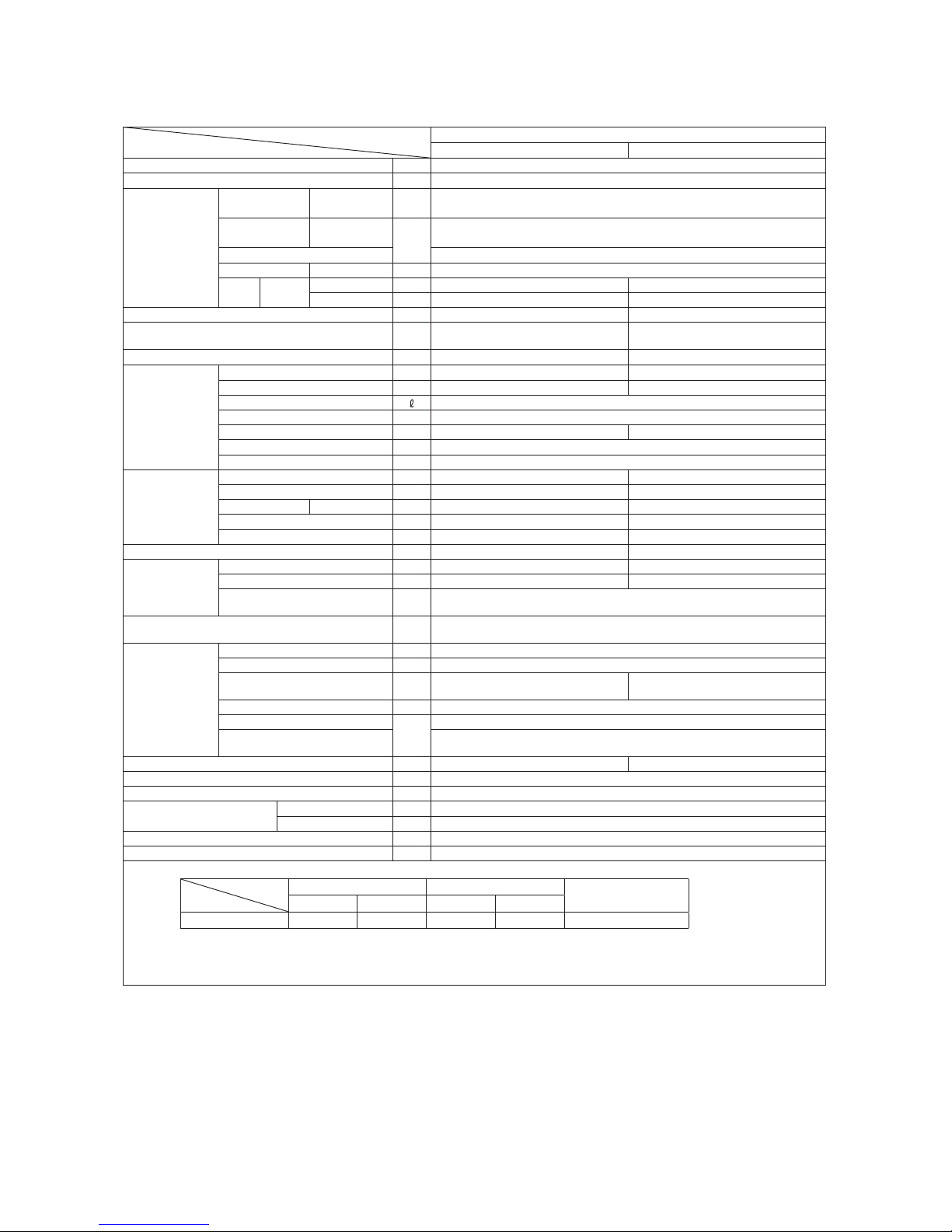
1. SPECIFICATIONS
Model
Item
SRK18CL (-3)
Indoor unit SRK18CL (-3) Outdoor unit SRC18CL (-3)
Cooling capacity (1) W 5000
Power supply 1 Phase, 220/230/240V, 50Hz
Operation
data (1)
Power
consumption
Cooling kW 1.70
Running
current
Cooling
A
8.0/7.7/7.3 (220/230/240V)
Inrush current 37
COP Cooling 2.94
Noise
level
Cooling
Sound level dB(A) Hi : 48 Me : 44 Lo : 42 50
Power level dB 64 65
Exterior dimensions (Height x Width x Depth) mm 309 x 890 x 251 640 x 850 (+65) x 290
Exterior appearance
(Munsell color)
Fine snow
(8.0Y 9.3/0.1) near equivalent
Stucco white
(4.2Y 7.5/1.1) near equivalent
Net weight kg 12 37
Refrigerant
equipment
Compressor type & Q'ty — QJ292PBB(Rotary type) x 1
Motor (Starting method) kW — 1.29 (PSC starting)
Refrigerant oil 0.45 (SONISO 4GSI or ATMOS NM56)
Refrigerant (3) kg R22 0.9 (Pre-Charged up to the piping length of 7m)
Heat exchanger Louver fins & inner grooved tubing M fins & inner grooved tubing
Refrigerant control Capillary tubes
Deice control Microcomputer control
Air handling
equipment
Fan type & Q'ty Tangential fan x 1 Propeller fan x 1
Motor W 27 40
Air flow Cooling CMM 12.8 38
Fresh air intake Not possible —
Air filter, Quality / Quantity Polypropylene net (washable) x 2 —
Shock & vibration absorber — Cushion rubber (for compressor)
Operation
control
Operation switch Wireless-Remote control —
Room temperature control Microcomputer thermostat —
Operation Display
RUN : Green, TIMER : Yellow, HI POWER : Green,
ECONO : Orange
Safety devices
Compressor overheat protection, Overcurrent protection,
Frost protection, Fan motor error protection
Installation
data
Refrigerant piping size (O.D) mm Liquid line: φ6.35 (1/4") Gas line: φ15.88 (5/8")
connecting method Flare connecting
Attached length of piping m
Liquid line : 0.55
Gas line : 0.49
—
Insulation for piping Necessary (Both sides), independent
Refrigerant line (one way) length
m
Max. 15
Vertical height difference between
outdoor unit and indoor unit
Max.10 (Outdoor unit is higher)
Max.10 (Outdoor unit is lower)
Drain hose Connectable (VP 16) —
Power cable —
Recommended breaker size A 20
Connection wiring
Size x Core number 1.5mm2 x 4 cores (Including earth cable)
Connecting method Terminal block (Screw fixing type)
Accessories (included)
Mounting kit
Optional parts —
Note (1) The data are measured at the following conditions.
Item
Operation
Indoor air temperature Outdoor air temperature
Standards
DB WB DB WB
Cooling 27˚C 19˚C 35˚C 24˚C ISO-T1, JIS C 9612
(2) This air-conditioner is manufactured and tested in conformity with the ISO.
(3) The operation data are applied to the 220/230/240V districts respectively.
(4) The refrigerant quantity to be charged includes the refrigerant in 7.5m connecting piping.
(Purging is not required even for the short piping.)
The pipe length is 7.5m.
Page 6
-
4
-
'12 • SRK-T-125
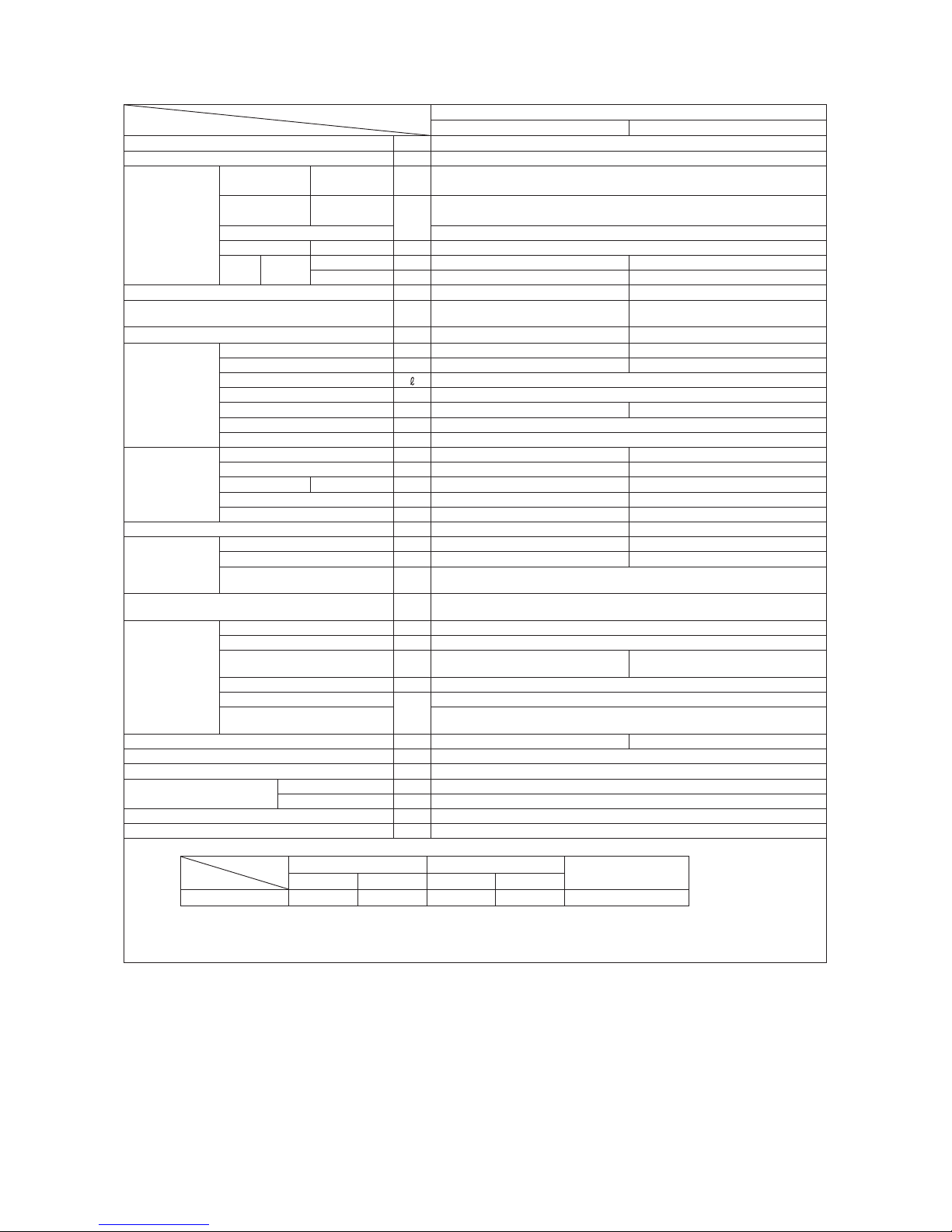
Model
Item
SRK18CL-6
Indoor unit SRK18CL-6 Outdoor unit SRC18CL-6
Cooling capacity (1) W 5000
Power supply 1 Phase, 220/230/240V, 50Hz
Operation
data (1)
Power
consumption
Cooling kW 1.72
Running
current
Cooling
A
8.1/7.8/7.4 (220/230/240V)
Inrush current 37
COP Cooling 2.91
Noise
level
Cooling
Sound level dB(A) Hi : 48 Me : 44 Lo : 42 50
Power level dB 64 65
Exterior dimensions (Height x Width x Depth) mm 309 x 890 x 251 640 x 850 (+65) x 290
Exterior appearance
(Munsell color)
Fine snow
(8.0Y 9.3/0.1) near equivalent
Stucco white
(4.2Y 7.5/1.1) near equivalent
Net weight kg 12 37
Refrigerant
equipment
Compressor type & Q'ty — QJ292PBB(Rotary type) x 1
Motor (Starting method) kW — 1.29 (PSC starting)
Refrigerant oil 0.45 (SONISO 4GSI or ATMOS NM56)
Refrigerant (3) kg R22 0.9 (Pre-Charged up to the piping length of 7m)
Heat exchanger Louver fins & inner grooved tubing M fins & inner grooved tubing
Refrigerant control Capillary tubes
Deice control Microcomputer control
Air handling
equipment
Fan type & Q'ty Tangential fan x 1 Propeller fan x 1
Motor W 27 40
Air flow Cooling CMM 12.8 38
Fresh air intake Not possible —
Air filter, Quality / Quantity Polypropylene net (washable) x 2 —
Shock & vibration absorber — Cushion rubber (for compressor)
Operation
control
Operation switch Wireless-Remote control —
Room temperature control Microcomputer thermostat —
Operation Display
RUN : Green, TIMER : Yellow, HI POWER : Green,
ECONO : Orange
Safety devices
Compressor overheat protection, Overcurrent protection,
Frost protection, Fan motor error protection
Installation
data
Refrigerant piping size (O.D) mm Liquid line: φ6.35 (1/4") Gas line: φ15.88 (5/8")
connecting method Flare connecting
Attached length of piping m
Liquid line : 0.55
Gas line : 0.49
—
Insulation for piping Necessary (Both sides), independent
Refrigerant line (one way) length
m
Max. 15
Vertical height difference between
outdoor unit and indoor unit
Max.10 (Outdoor unit is higher)
Max.10 (Outdoor unit is lower)
Drain hose Connectable (VP 16) —
Power cable —
Recommended breaker size A 20
Connection wiring
Size x Core number 1.5mm2 x 4 cores (Including earth cable)
Connecting method Terminal block (Screw fixing type)
Accessories (included)
Mounting kit
Optional parts —
Note (1) The data are measured at the following conditions.
Item
Operation
Indoor air temperature Outdoor air temperature
Standards
DB WB DB WB
Cooling 27˚C 19˚C 35˚C 24˚C ISO-T1, JIS C 9612
(2) This air-conditioner is manufactured and tested in conformity with the ISO.
(3) The operation data are applied to the 220/230/240V districts respectively.
(4) The refrigerant quantity to be charged includes the refrigerant in 7.5m connecting piping.
(Purging is not required even for the short piping.)
The pipe length is 7.5m.
Page 7
-
5
-
'12 • SRK-T-125
G
F
Space for installation and service when viewing from the front
Outlet for down piping
(Refer to the above view)
D C
A
E
B
Terminal block
881.9
59.926 20.9
59.9
46.5
61.5
46.5
61.5
890
309
9 61.5
3251
50 120 650 120 100
220 450 220
35 35
48.9222.5
48
48
5.7
295.4 7.9
15
(Service space)
70
Unit
54
46.5
(Service space)
(Service space)
(Service space)
Installation plate
491.1
520.8
559.1
58
61.5
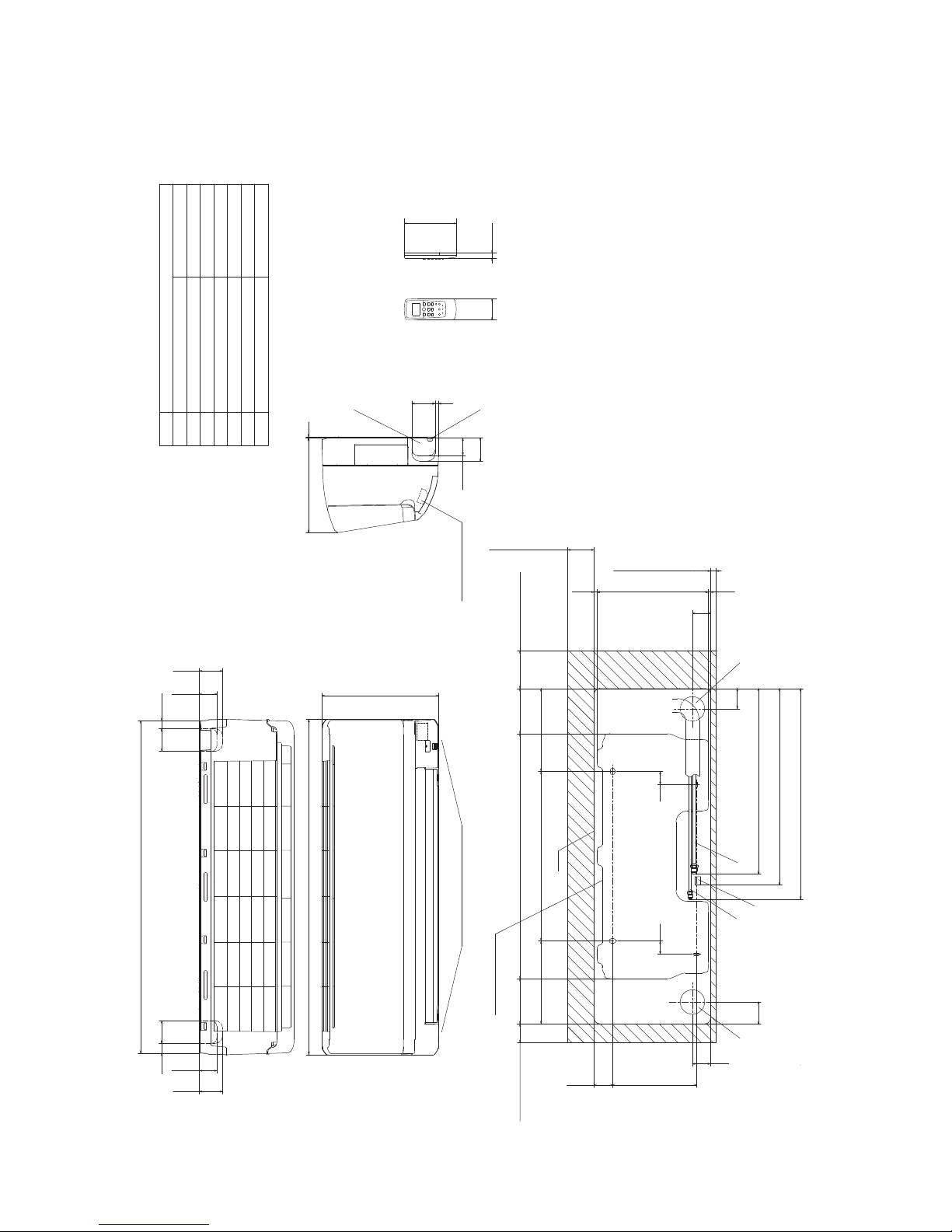
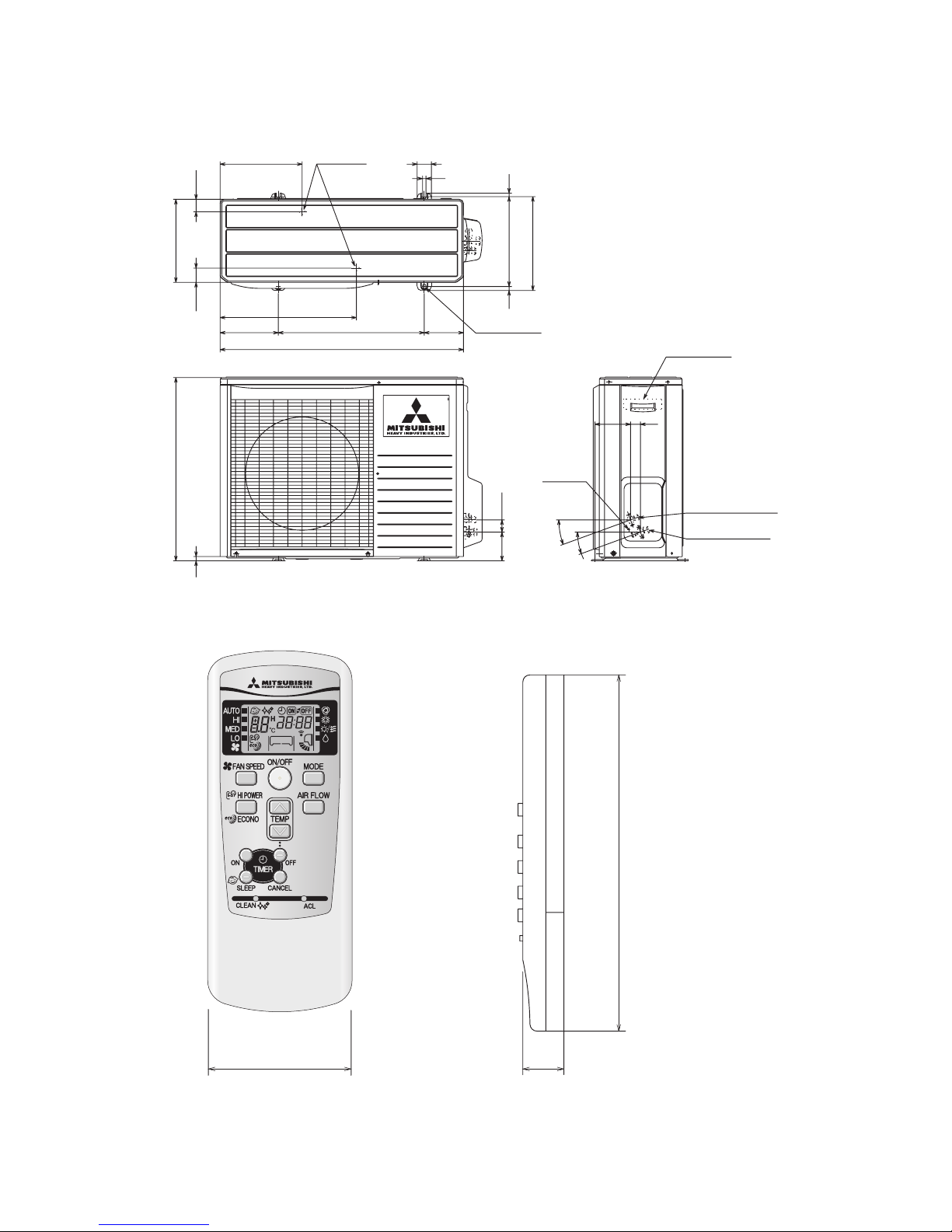
2. EXTERIOR DIMENSIONS
(1) Indoor units
Model SRK18CL(-3) (-6)
Hole on wall for right rear piping
Hole on wall for left rear piping
Gas piping
Outlet for piping(on both side)
Drain hose
Outlet for wiring
Liquid piping
F
G
E
CDB
Symbol
A
(ø65)
VP16
ø6.35(1/4")(Flare)
Content
ø15.88(5/8")(Flare)
(ø65)
Wireless remote controller
Unit:mm
60
150
17.3
Page 8
-
6
-
'12 • SRK-T-125
Drain holes
286.4
12
50
290
49.6
43.5
850
203.1
510 136.9
476
Elogated hole
(2-12 x16)
314
12
328
Terminal block
Service valve (Liquid)
ø6.35 (1/4'')
Service valve (Gas)
ø15.88 (5/8'')
Ground
terminal
124
34.6
20
°
20
°
42.7
100.3
15
640
14
(2) Outdoor unit
Model SRC18CL(-3) (-6)
Unit: mm
(3) Wireless remote controller
Unit: mm
60
17.3
150
Page 9
-
7
-
'12 • SRK-T-125
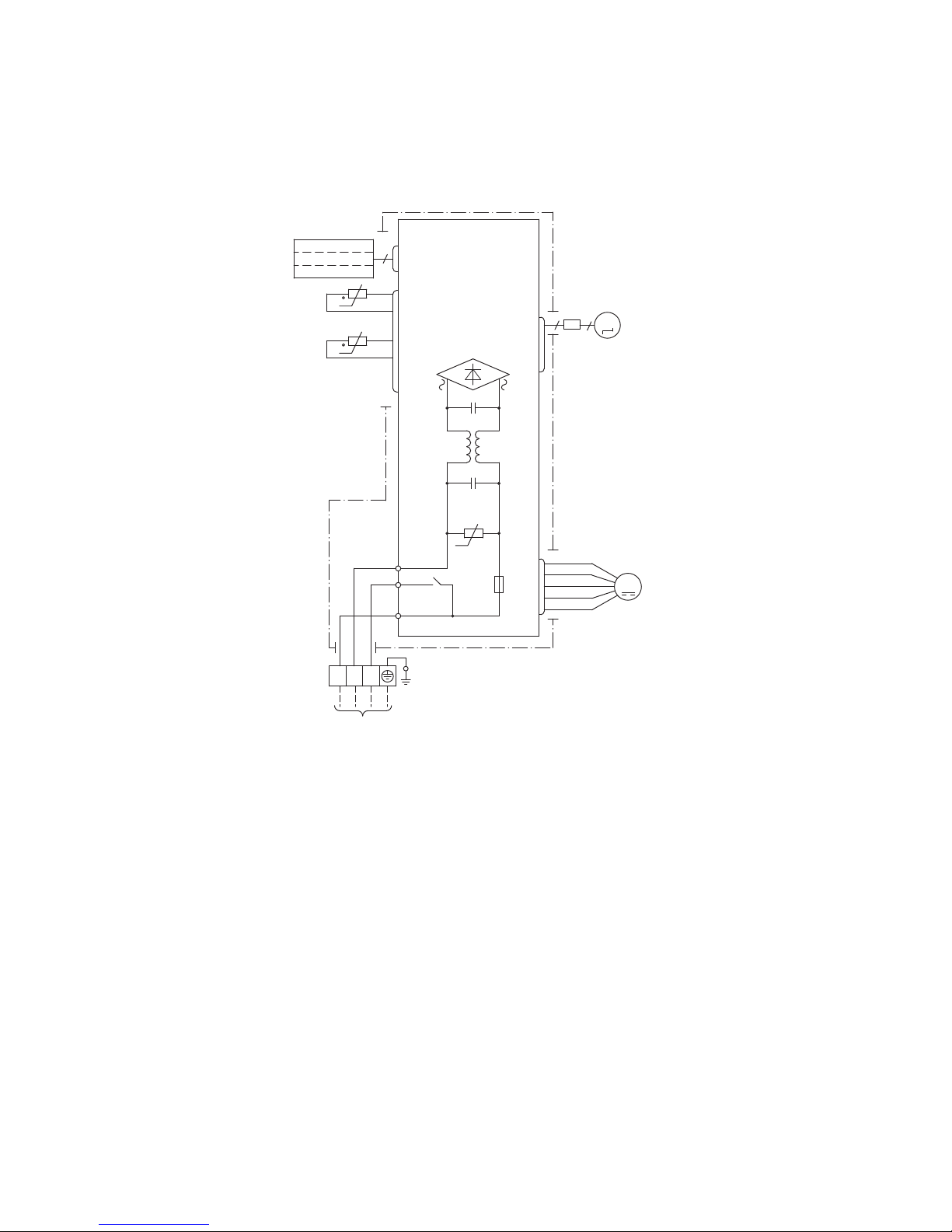
3. ELECTRICAL WIRING
(1) Indoor units
Model SRK18CL(-3) (-6)
250V
FUSE
3.15A
S/N
VARISTOR
FAN MOTOR
CNU
U
M
1
3
4
5
6
TO OUTSIDE
T
TERMINAL
1
2/N
3
UNIT
BLOCK
HEAT
EXCHANGER
BOARD
CIRCUIT
PRINTED
FLAP
CNX2
M
5
MOTOR
BLUE
WHITE
RED
WHITE
BLACK
BLUE
YELLOW
BLACK
CNG
CNE
DISPLAY
WIRELESS RECEIVER
BACK-UP SW
9
HEAT EXCHANGER
SENSOR 1
ROOM TEMP.
SENSOR
52C-4
52C-3
t
t
5
Page 10
-
8
-
'12 • SRK-T-125
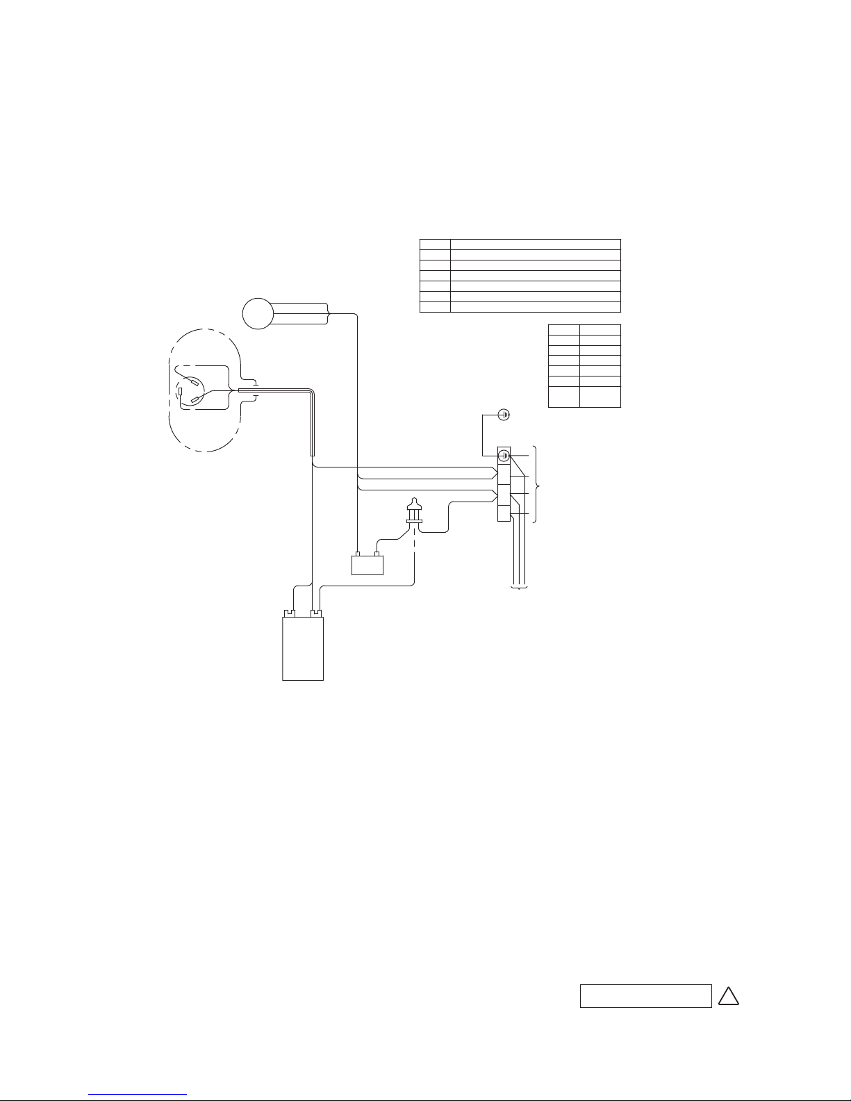
(2) Outdoor units
Model SRC18CL(-3) (-6)
Sh
WH
BL
OR
RD WH WH
WH
OR
OR
FMo
WH
BL
BL
WH
R
C
CM
S
RD
WH
BL
Y/GN
MARK
RD RED
COLOR
ORANGE
BLACK
BLUE
BK
OR
BL
WH WHITE
INDOOR UNIT
POWER SOURCE
220-240V 50Hz
Y/GN
YELLOW/
GREEN
CFO
CC
2/N
3
T
1/L
RCR011G003BC
RUNNING CAPACITOR FOR COMPRESSOR
RUNNING CAPACITOR FOR FAN MOTORCFO
CC
FAN MOTOR
COMPRESSOR MOTOR
FMo
CM
PARTS NAME
SYMBOL
MEANING OF MARK
CONNECTOR
TERMINAL BLOCKT
Sh
G
RCR011G0 0 3 B C
Page 11
-
9
-
'12 • SRK-T-125
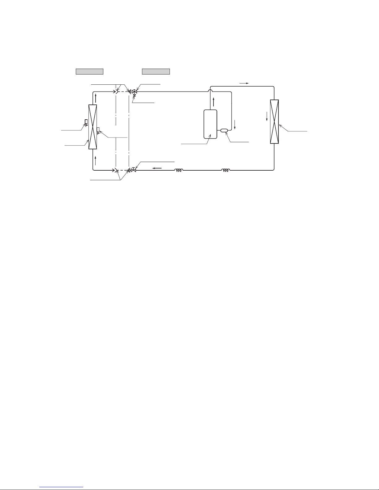
4. PIPING SYSTEM
Model SRK18CL(-3) (-6)
Outdoor unitIndoor unit
Room temp.
sensor
Heat
exchanger
Flare connecting
Heat
exchanger
sensor
Piping
(Liquid)
ø
6.35
Piping
(Gas)
ø15.88
Check joint
Service valve (Liquid)
Flare connecting
Heat
exchanger
Compressor
Capillary tube Capillary tube
Accumulator
Service valve
(Gas)
Page 12
-
10
-
'12 • SRK-T-125
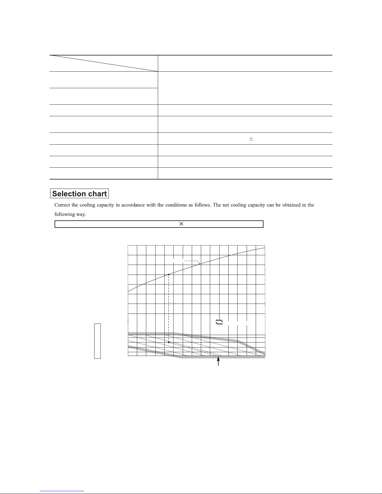
5. RANGE OF USAGE & LIMITATIONS
Net capacity = Capacity shown on specification Correction factors as follows.
(1) Coefficient of cooling capacity in relation to temperatures
All models
Models
Item
Indoor return air temperature
(
Upper, lower limits
)
Outdoor air temperature
(
Upper, lower limits
)
Refer to the selection chart
Refrigerant line (one way) length
Max. 15m
Max. 10m (Outdoor unit is higher
)
Max. 10m (Outdoor unit is lower
)
Min. 3 minutes
Max. 10 times/h
Min. 85% of rating
Vertical height difference between
outdoor unit and indoor unit
Power source voltage
Voltage at starting
Frequency of ON−OFF cycle
ON and OFF interval
Rating 10%
16 18 20 22
21
25
30
35
40
0.6
0.7
0.8
0.9
1.0
1.1
1.2
1.3
43
24
ISO-T1 Standard ConditionIndoor air W.B. temperature ° C W.B.
Cooling
Applicable range
Coefficient of cooling
capacity in
relation to temperature
Cooling operation
Outdoor air D.B.
temperature
°C D.B.
Page 13
-
11
-
'12 • SRK-T-125
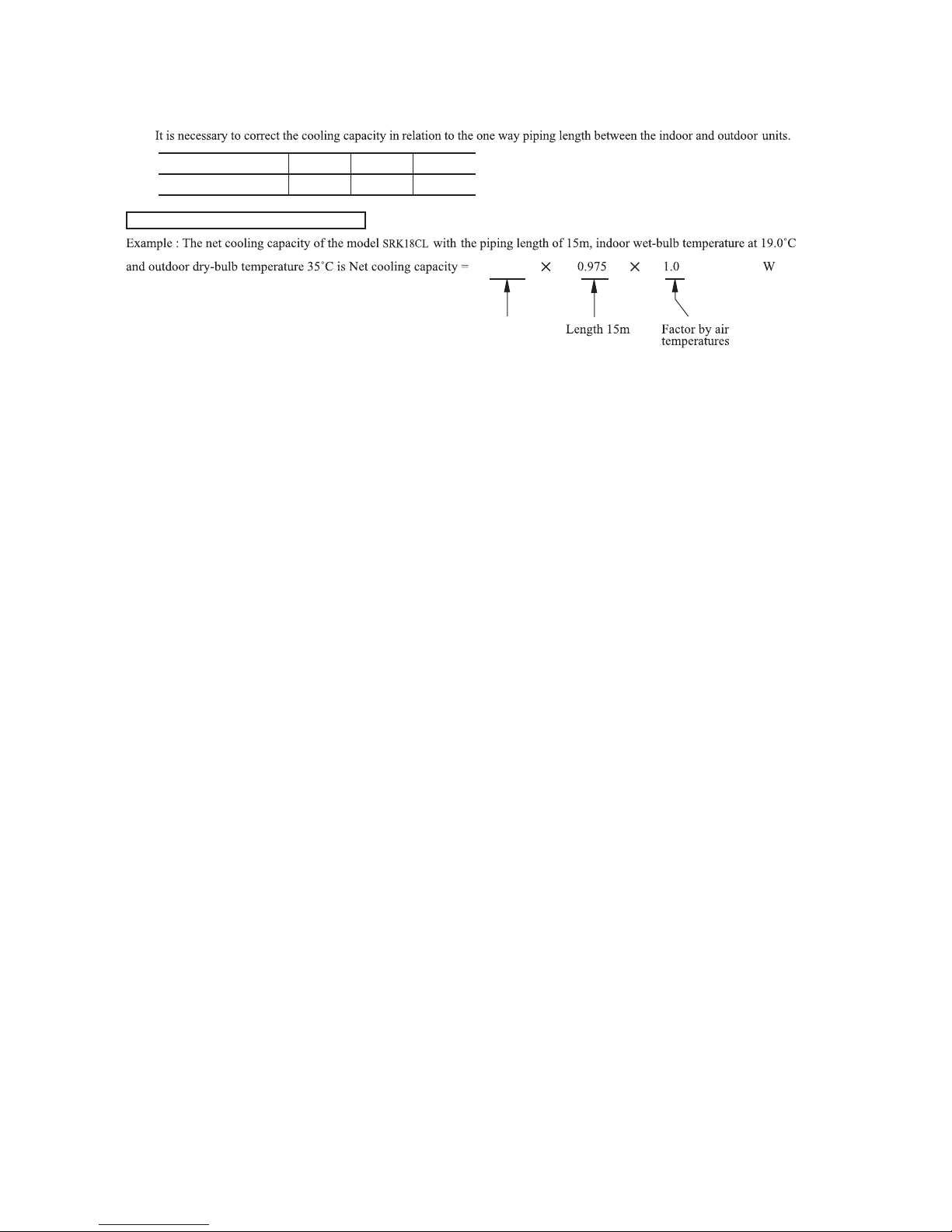
(2) Correction of cooling capacity in relation to one way length of refrigerant piping
How to obtain the cooling capacity
=
Piping length [m]
Cooling
7
1.0
10
0.99
15
0.975
SRK18CL
5000 4875
Page 14
-
12
-
'12 • SRK-T-125
6. APPLICATION DATA
Safety precautions
• When installing the unit, be sure to check and satisfy the requirements in the selection of installation location, power supply specifica-
tions, usage limitation (piping length, height differences between indoor and outdoor units, power supply voltage and etc.) and installation spaces.
• Read the “SAFETY PRECAUTIONS” carefully first of all and strictly follow it during the installation work in order to protect yourself.
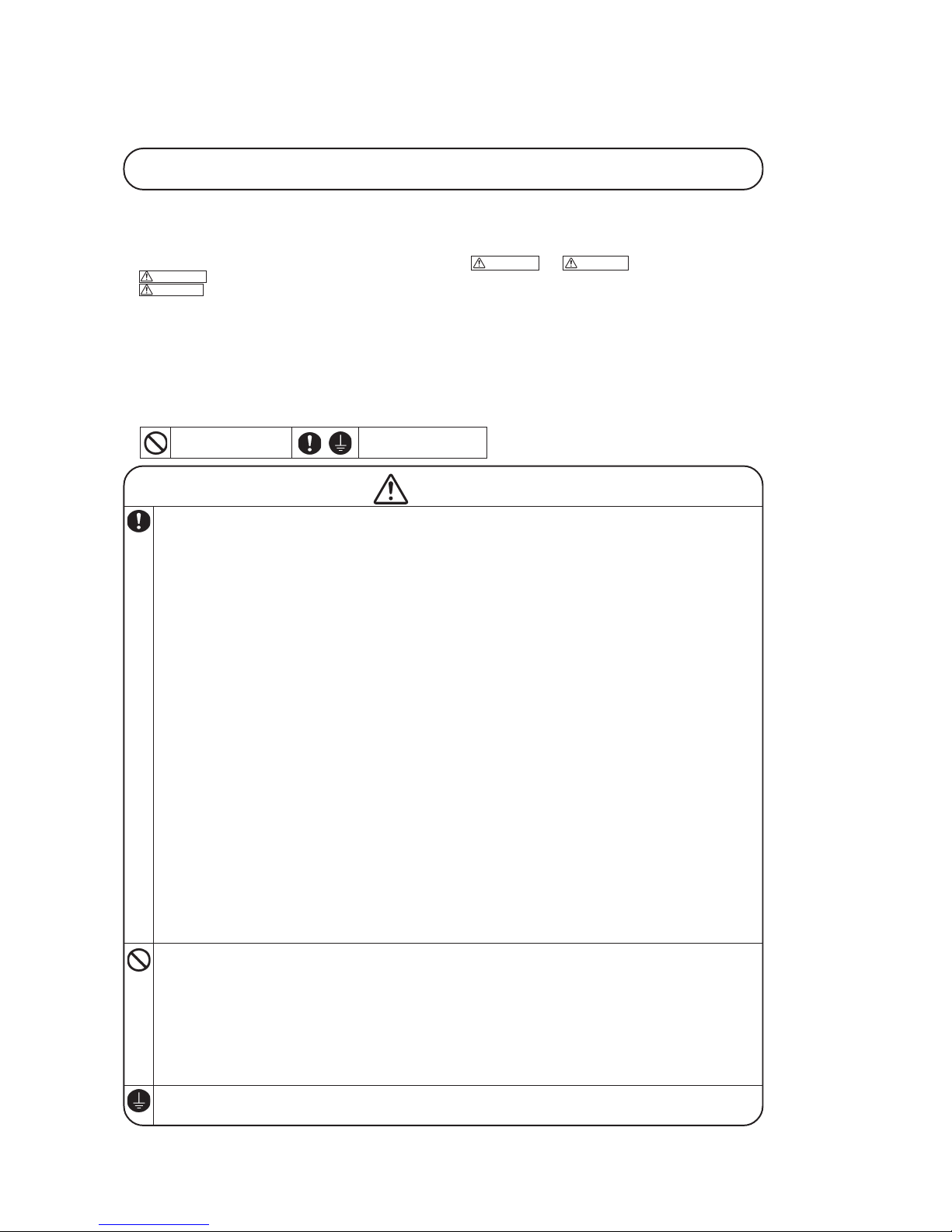
• The precautionary items mentioned below are distinguished into two levels, WARNING and CAUTION .
WARNING : Wrong installation would cause serious consequences such as injuries or death.
CAUTION : Wrong installation might cause serious consequences depending on circumstances.
Both mentions the important items to protect your health and safety so strictly follow them by any means.
• Be sure to confirm no anomaly on the equipment by commissioning after completed installation and explain the operating methods as well as the
maintenance methods of this equipment to the user according to the owner’s manual.
• Keep the installation manual together with owner’s manual at a place where any user can read at any time. Moreover if necessary, ask to hand
them to a new user.
• For installing qualified personnel, take precautions in respect to themselves by using suitable protective clothing, gloves, etc., and then perform
the installation works.
• Please pay attention not to fall down the tools, etc. when installing the unit at the high position.
• If unusual noise can be heard during operation, consult the dealer.
• The meanings of “Marks” used here are shown as follows:
Ne ve r do it un de r an y
circumstances.
Always do it according to
the instruction.
WARNING
• Insta llation m ust be ca rried out by the qu alified i nstaller.
If you install th e sy stem by yourse lf, it m ay cause serious t rouble such as
water leaks, ele ctric sh ocks, fir e and personal i njury, a s a resu lt of a system
malfunct ion.
• Insta ll the sy stem in f ull accor dance with the inst ruction m anual.
Incorrec t installa tion may ca use bursts , personal injury, wat er leaks, e lectric
shocks a nd fire.
• Be su re to use only for househol d and resi dence.
If this appliance is installed in inferi or en vironment suc h as mach ine shop
and etc. , it can cause malfunction.
• Use the ori ginal accessories and the specified components for ins talla-
tion.
If parts o ther than t hose prescribed by u s are used, It may caus e water le aks,
electric shocks, fire and p ersonal i njury.
• Insta ll the un it in a l ocation w ith good s upport.
Unsuitab le installa tion locati ons can cause the unit to fall and cause mate rial
damage a nd personal injury.
• Venti late the working area well in t he event of refr igerant leakage d ur-
ing inst allation.
If the refrigerant comes into contact with na ked flames, poisonous gas is
produced .
• When i nstalling in small ro oms, take p revention measures n ot to excee d
the density limit of refrigerant in the event of leakage, referred by th e
formula (accordan ce with I SO5149).
If the densit y of refriger ant exc eeds th e limit , pleas e consu lt the dealer and
install the ventilation system, otherw ise lack of oxyge n can occur, which can
cause se rious acc ident.
• After c ompleted installatio n, check tha t n o refrigera nt leaks from t he
system.
If refrigerant leaks into the roo m a nd comes int o contact with an oven or
other ho t surface , poisonous gas is produced.
• Tight en the fl are nut b y torque wrench wit h specifi ed method .
If the flare nut were tig htened with ex cess tor que, th is may cause burst and
refriger ant leaka ge after a long per iod.
• Do not ope n the operatio n valves for liquid line an d gas line u ntil com -
pleted r efrigeran t piping work, air tightness test and evacuati on.
If the c ompresso r is oper ated in state of opening operation valves before
complete d connec tion of refrige rant piping wor k, air can be sucked into refrigeran t circuit, whi ch can cause bus t or personal in jury due to anoma lously
high pre ssure in the refrigerant.
• Do not put the dr ainage pi pe directl y into dra inage chan nels where poi-
sonous g ases such as sulph ide gas ca n occur.
Poisonou s gases will fl ow into the roo m through dra inage pipe an d seriously
affect t he user’s health and safety.
• Ensur e that no air enters in the re frigerant circu it when the unit is in-
stalled and remove d.
If a ir en ters in th e ref rigerant circuit, the pressur e in the refr igerant circuit
becomes too high, which can cause bu rst and p ersonal i njury.
• Do not proces s, splice the power cord, or share a socket with other power
plugs.
This ma y cause fire or electric shock d ue to d efecting contact, defecting insulation and over-current e tc.
• The electrical installation must be carr ied out by th e qu alified electri-
cian in accor dance with “t he norm for elect rical work” an d “ national
wiring regulation”, and the s ystem must b e conn ected to the dedic ated
circuit.
Power supply w ith ins ufficient capacit y and incorrec t functi on done by im proper w ork can c ause electric shock s and fir e.
• Be su re to shu t off the power be fore start ing elect rical wor k.
Failure t o shut off the power can cause electric shocks, u nit failur e or incor rect fun ction of equipment.
• Be sure to use the ca bles conf ormed to saf ety standa rd and cable
ampacity for powe r distrib ution wor k.
Unconfor mable cables can cause elect ric leak, anomalous heat prod uction or
fire.
• This appliance mu st be connected to main power supply by means o f a
circuit br eaker or swit ch (fuse:20 A) with a conta ct separati on of at least
3mm.
• Wh en pl uggi ng th is ap pli anc e, a p lug con form ing t o th e nor m
IEC60884 -1 must b e used.
• Use the prescribed cables for e lectrical connectio n, tighten the cab les
securely in terminal block a nd relieve the cab les correctly to p revent
overload ing the t erminal b locks.
Loose conn ections or c able mounti ngs can cause anomalous h eat product ion
or fire.
• Arran ge the wirin g in the cont rol box so that it canno t be pushed up
further into the box. Inst all the se rvice pan el correc tly.
Incorrec t install ation may result in overheat ing and f ire.
• Be su re to fix up the s ervice pa nels.
Incorrec t fixin g can cause electric shocks or f ire due to i ntrusion of dust or
water.
• Be sure to switch off the power supply in the event of instal lation, inspe c-
tion or servicing .
If the powe r s upply is not s hut off, there is a risk of elec tric shocks, unit
failure or person al injury due to th e unexpec ted start of fan.
• Stop the compressor before disconnecting refrigerant p ipes in cas e of
pump dow n operati on.
If disconnecting refri gerant pipe s in state of openi ng operatio n valves befor e
compress or sto pping, air can be suc ked, which can ca use b urst o r pers onal
injury d ue to ano malously high press ure in th e refrige rant circ uit
• Only u se prescrib ed optional parts. The in stallatio n must be carr ied out
by the q ualified installer .
If you ins tall the sy stem by yourself, it ca n cause serious trouble such as
water le aks, electric shock s, fire.
• Do not bundle, wind or process for the power cord. Or, do not deform
the powe r plug du e to trea d it.
This may cause fi re or heating.
• Do no t vent R 410A into the atm osphere : R410A is a fluor inated gr een-
house g as, cov ered by the Kyoto Pr otocol w ith Glo bal Warm ing Pote ntial (GW P)=1975.
• Do no t run the unit wit h removed panels or protecti ons.
Touching rotati ng equi pments, hot surfaces or high v oltage parts c an caus e
personal injury d ue to entrapment, b urn or el ectric sh ocks.
•
Do not perfor m any change of pro tective devi ce itself or its setup conditi on.
The forced ope ration by short -circuiting protective device of pressur e switch
and temp erature controller or the use of n on speci fied comp onent can cause
fire or burst.
• Carry out the electrica l work fo r ground l ead with care.
Do not connect the ground l ead to the gas line , water line, light ning cond uctor or t elephone line’s gr ound lead. Incorrec t groundi ng can ca use unit f aults suc h
as elect ric shock s due to short-cir cuiting.
Page 15

-
13
-
'12 • SRK-T-125
CAUTION
• Us e the circuit bre aker with sufficient brea king capacity.
If the breaker does not have sufficient breaking capacity, it can cause the unit
malfunction and fire.
• Ea rth leakage breaker must be installed.
If the earth leakage breaker is n ot installed, it can caus e electric shocks.
• In stall isolator o r di sconnect swi tch on t he p ower supply wiring i n ac -
cordance with th e local codes and regulat ions.
• B e sure to install indo or unit prope rly according to the instr ucti on
manual in order to run off the dr ainage s moothly.
Improper installation of indoor unit ca n cause dropping water into the room
and damaging per sonal property.
• In stall the draina ge p ipe to run off drainage securely accordi ng t o th e
installation manual.
Incorrect instal lation o f the drainage p ipe can cause dr opping w ater int o the
room and damaging personal proper ty.
• Be sure to inst all the drainage pipe w ith descending slope of 1/100 or
more, an d not to make tra ps and air-bleedings.
Check if the drainage runs off securely durin g commissioning and ensure the
space for inspection and maintena nce.
• Af ter maintenance, all wiring, wiring ties and the like, should be re-
turned to their original state and wiri ng route, and the necessary cle arance from all me tal parts should be secur ed.
• Se cure a space for inst allation, inspec tion an d maintenance s pecified in
the manual.
Insufficient space can result in accident such as personal injury due to falling
from the installation place.
• Ta ke care when carrying the unit by hand.
If the unit weights more than 20kg, it must be carried by two o r mor e per-
sons. Do not carry by the plastic straps, always use the carry handle when
carrying the unit by hand. Use gloves to minimize the risk of cuts by the
aluminum fins.
• Di spose of any packing mate rials correctly.
Any remaining packing materials can cause personal injury as it contains
nails and wood. And to avoid danger of suffocation, be sure to keep the pla stic wrapper away from children an d to dispose after tear i t up.
• Fo r installation work, be careful not to get injured with the heat ex-
changer, piping flare portion or screws e tc.
• Be sure to insulate the refrigerant pipes so as not to condens e the ambi-
ent air moisture on them .
Insufficient insulat ion can cause condensation, which can lead to moisture
damage on the ceiling, floor, fur niture and any other valu ables.
• Wh en p erform the air conditioner operation ( cooling or drying ope ra-
tion) in whi ch ventilator is installed in the room. In this case, us ing the
air conditioner in parallel with the ventilator, there is the possibility that
drain water may backflow in accordance with the room l apse into the
negative pressure status. Th erefore, set up the opening port such a s incorporate the air into the room that ma y appropriate to ventil ation (For
example; Open the do or a little ). In addit ion, just a s above, so set up the
opening port if the room laps e into negative pressure status due to register of the wind for the high rise apartme nt etc.
• Do not install the unit in the locations lis ted belo w.
• Locations where carbon fiber, metal powder or any powder is floating.
• Locations where any substances that can affect the unit such as sulphide
gas, chloride gas, acid and alkal ine can occur.
• Vehicles and ships.
• Locations where cosmetic or special sprays are often used.
• Locations with direct exposure of oil mist and steam such as ki tchen and
machine plant.
• Locations where any mach ines which generate high frequency har monics
are used.
• Locations with salty atmospheres such as coastlines.
• Locations with heavy snow (If installed, be sure to provide base flam e and
snow hood mentioned in the manual ).
• Locations where the unit is exposed to chimney smoke.
• Locations at high altitude (more than 1000m high).
• Locations with ammonic atmospheres.
• Locations where heat radiation from other heat source can af fect the unit.
• Locations without good air circulation.
• Locations with an y obstacles which can prevent inlet and outlet air of the
unit.
• Locations where short circuit of air can occur ( in case of multiple units
installation).
• Locations where strong air blows against the air outlet of o utdoor unit.
It can cau se remarkable decre ase in performance, corrosion and damage of
components, malfunction and fire.
• Do not install the indoor unit in t he location s listed below (Be sure to
insta ll the indoor unit according to t he installa tion manual for each
model because ea ch indoor unit ha s each l imitation).
• Locations with an y obstacles which can prevent inlet and outlet air of the
unit.
• Locations where vibration can be amplified due to insufficient strength of
structure.
• Locations where the infrared receiver is exposed to the direct sunlight or
the strong light beam (in case of the infrared specificati on unit).
• Locations where an equipment affected by high harmonics is placed (TV
set or radio receiver is placed w ithin 1m).
• Locations where drainage cannot run off safely.
It can affect performance or func tion and etc.
• Do not install the outdoor unit in the locat ions lis ted below.
• Locations where discharged hot air or operating sound of the outdoor unit
can bother neighborhood.
• Locations where outlet air of the outdoor unit blows directl y to plants.
• Locations where vibration can be amplified and transm itted due to insuffi-
cient st rength of structure.
• Locations where vibra tion and operation sound generated by the outdoor
unit can affect seriously (on the wall or at the place nea r bed room).
• Locations where an equipment affected by high harmonics is placed (TV
set or radio receiver is placed w ithin 1m).
• Locations where drainage cannot run off safely.
It can affect surrounding environ ment and cause a claim.
• Do no t install the unit ne ar the location wh ere leakage of com bustible
gases ca n occur.
If leaked gases accumulate around the unit, it can cause f ire.
• Do not install the unit where corrosive gas (such as sulfurous acid gas
etc.) or combustible gas (such as thin ner and petro leum gases) can accumulate or collect, or where volat ile combus tible substances are handled.
Corrosive gas can cause corrosion of heat exchanger, breakage of plastic
parts and etc. And combustible ga s can cause fire.
• Do not use the in door uni t at the place where wa ter spla shes may occur
such as in laundries.
Since the indoor unit is not waterproof, it can cause e lectric s hocks and fire.
• Do not install nor use the system close to the equipment that generate s
electromagnetic fields or high frequency harmonic s.
Equipment such as inverters, standby generators, medical high frequenc y
equipments and telecommunication equipments can affect th e system, and
cause malfunc tions and breakdowns. The system can also affect medical
equipment and telecommunication equipment, and obstruct its function or
cause jamming.
• Do not place any va luable which will b e damaged by getting wet under
the indoor unit.
When the relative humidity is higher than 80% or drainage pipe is clogged,
condensation or drainage water can drop and it can cause the damage of valuables.
• Do not install the remote c ontrol at the dir ect sunl ight.
It can cause malfunction or defor mation of the remote cont rol.
• Do not us e the unit for special purposes such as storing foods, cooling
precision instru ments and preserv ation of animals, plants or art.
It can cause the damage of the it ems.
• Do not install the outdoor unit in a location where insects an d small ani-
mals can inhabit .
Insects and small animals can enter the electric pa rts and cause damage or
fire. Instruct the user to keep t he surroundings clean.
• Do not use the base f lame for outdoor uni t wh ich is corroded or dam-
aged due to long periods of opera tion.
Using an old and damage base flame can c ause the unit falling down and
cause pe rsonal injury.
• Do not use any materials other th an a fuse with the cor rect rati ng in the
location where f uses are to be us ed.
Connecting the circuit with copper wi re or othe r metal thread can cause unit
failure and fire .
• Do not touch any buttons wi th wet hands.
It can c ause electric shocks.
• Do not touch a ny refrigerant pipes with y our hands when the system is
in operation.
During operation the refrigerant pipes become extremely hot or extremely
cold depending the operatin g condition, and it can cause burn inju ry or fros t
injury.
• Do not touch the suction or aluminum fin on the outd oor unit.
This may cause injury.
• Do not put anything on the outdoor unit and operatin g unit.
This may cause damage the objects or injury due to falling to the object.
Page 16

-
14
-
'12 • SRK-T-125
Necessary tools for the installation work
1 Plus headed driver (Phillips screwdriver)
2 Knife
3 Saw
4 Tape measure
5 Hammer
6 Spanner wrench
7 Torque wrench
8 Hole core drill (65mm in diameter)
9 Wrench key (Hexagon)
[4m/m]
10 Vacuum pump
11
Vacuum pump adapter
(Anti-reverse flow type)
12 Gauge manifold
13 Change hose
14 Flaring tool set
15 Gas leak detector
16
Gauge for projection adjustment (Used when flare
is made by using conventional flare tool)
17 Pipe bender
( )
Standard accessories
(Installation kit) Q'ty
Accessories for indoor unit
①
Installation plate
1
(Attached to the rear of the indoor unit)
② Wireless remote control 1
③ Remote contorol holder 1
④
Tapping screws
4
(for installation board 4dia. by 25mm)
⑤
Wood screw
2
(for remote contorol switch holder 3.5dia. by 16mm)
⑥
Baterry [R03 (AAA, Micro) 1.5V]
2
Option parts Q'ty
ⓐ 1etalpgnilaeS
ⓑ 1eveelS
ⓒ 1etalpnoitanilcnI
ⓓ 1yttuP
ⓔ Drain hose (extention hose) 1
ⓕ
Piping cover
1
(for insulation of connection piping)
Selection of installation location
Where there is no obstructions to the air flow and where
the cooled air can be evenly distributed.
A solid place where the unit or the wall will not vibrate.
A place where there will be enough space for servicing.
(Where space mentioned right can be secured)
Where wiring and the piping work will be easy to conduct.
The place where receiving part is not exposed to the direct rays of the sun or the strong rays of the street lighting.
A place where it can be easily drained.
A place separated at least 1m away from the television or
the radio.
(To prevent interfence to images and sounds.)
A place that home appliance and household goods, etc.
aren’t below unit.
Avoid installing this unit in place where there is much oil
mist.
Places where there is no electric equipment or household
under the installing unit.
INDOOR UNIT
14.0 ~ 8 2.0N · m
(1.4 ~ 8 .2kgf · m)
( )
Designed spec ifically
for R22
( )
Designed spec ifically
for R22
( )
Designed spec ifically
for R22
( )
Designed spec ifically
for R22
( )
Designed spec ifically
for R22
Before installation check that the power supply matches the air conditioner.
BEFORE INSTALLATION
(Install at location that meets the following conditions, after getting approval from the customer)
A place where the air conditioner can be received the signal surely during operating the wireless remote control.
Places where there is no affected by the TV and radio etc.
Do not place where exposed to direct sunlight or near
heat devices such as a stove.
Wireless remote control
Installation plate
5 cm mi
nimum
from the
w
all
10 cm mi
nimum
from the w
all
10 cm minimum from the ceiling
Wireless remote control
Remote control holder
Wood screws
Sleeve
(sold separately)
CAUTION
putty
putty
Indoor side
Outdoor side
Completely seal the hole
on the wall with putty.
Otherwise, furniture, or
other, may be wetted by
leaked water or dewing.
Page 17

-
15
-
'12 • SRK-T-125
Installation of indoor unit
Limitations for one way piping length and vertical height difference
Total one way piping length ( ) Max. 15 m
Vertical height difference (h) Max. 10 m
h
A place where good air circulation can be obtained and where rain,
snow or sunshine will not directly strike the unit.
A place where discharged hot air or unit’s operating sound will not
be a nuisance to the neighborhood.
A place where servicing space can be secured.
A place where vibration will not be enlarged.
*Avoid installing in the following places.
•A place near the bedroom and the like, so that the operation
noise will cause no trouble.
•
A place where there is possibility of flammable gas leakage.
•A place exposed to strong wind.
•In a salt-laden atmosphere or a place where the generation of oil mist, vapor or fume is expected.
Blowing out port and suction port on the back side of the unit can be installed at a distance of 10cm from walls.
In case the barrier is 1.2m or above in height, or is overhead, the
sufficient space between the unit and wall shall be secured.
When the unit is installed, the space of the following dimension and above shall be secured.
OUTDOOR UNIT
60 cm MIN
Air intake
10 cm MIN
10 cm
MIN
Air outlet
Air
intake
No obstacles
(Service space
for electrical
parts)
Note (1) If the wall is higher than 1.2 m or a ceiling
is present, distances larger than indicated
in the above table must be provided.
( )
Look for the inside wall structures (Intersediats support or pillar and finally install
the unit after level surface has been checked.)
450
Level position (2 locations)
Mating mark for
level surface
Fixing on concrete wall
Use of nut anchor Use of bolt anchor
Nut
(M6)
Mounting
board
Mounting
board
Max.10
Bolt
(M6 12)
INSTALLATION SPACE (INDOOR UNIT)
(FRONT VIEW)
50
Space for
service
Space for
service
120
220
650
450 220
100
120
35
35
58
54
520.8
491.1
559.1
49222.5
48
100 Space for service 15 Space for service
7.7295.75.6
48
Indoor unit
Installation board
Drain hose (ø16)
Piping for Gas
Piping for Liquid
Piping hole (ø65)
Piping hole (ø65)
Relation between setting plate and indoor unit
Piping for Liquid : ø6.35
Piping for Gas : ø12.7
Installation of Installation plate
Standard hole
Nothing is connected to
this hole on the back of
indoor unit.
Adjustment of the installation plate in the horizontal direction is to be conducted
with four screws in a temporary tightened state.
Adjust so the plate will be level by turning the board with the standard hole
as the center.
Drill a hole with whole core drill. In case of rear piping draw out, cut off the lower
and the right side portions of the sleeve collar.
When drilling the wall that contains a metal lath, wire lath or metal plate, be sure to use pipe hole sleeve sold separately.
Drilling of holes and fixture of sleeve (Option parts)
Top
Indoor side
Outdoor side
Thicknese of the wall + 1.5cm
5
65
Indoor side Outdoor side Installed state
Turn to
tighten
Page 18

-
16
-
'12 • SRK-T-125
1. Remove the drain hose. 2. Remove the drain cap. 3. Insert the drain cap. 4. Connect the drain hose.
gnipiPediSthgiRgnipiPediStfeL
Preparation of indoor unit
Pipe
Drain hose
① Mounting of connecting wires
ⓐ Open the air inlet panel.
ⓑ Remove the lid.
ⓒ Remove the wiring clamp.
ⓓ Connect the connecting wire securely to the terminal block.
Use cable for interconnection wiring to avoid loosening of the
wires.
CENELEC code for cables Required field cables.
H05RNR4G1.5 (Example) or 245IEC57
H Harmonized cable type
05 300/500 volts
R Natural-and/or synth. rubber wire insulation
N Polychloroprene rubber conductors insulation
R Standed core
4or5 Number of conductors
G One conductor of the cables is the earth conductor (yel-
low/green)
1.5 Section of copper wire (mm
2
)
• Connect the connection wire securely to the terminal block. If
the wire is not affixed completely, contact will be poor, and it
is dangerous as the terminal block may heat up and catch fire.
• Take care not to confuse the terminal numbers for indoor
and outdoor connections.
• Earth lead wire shall be longer than the other lead wires for
the electrical safety in case of the slipping out of the cord
from the anchorage.
• The earth line of power cord must be properly earthed.
• Affix the connection wire using the wiring clamp.
ⓔ Fix the connecting wire by wiring clamp.
ⓕ Attach the lid.
ⓖ Close the air inlet panel.
② Shaping the pipe ③ Taping of the exterior
• Hold the bo ttom of th e pipe an d change i ts
directio n before stretch ing it and shaping it .
• Tape only the po rtion that run s through the wall.
Always tap e the cro ssover wires wit h the pipe .
④ Cautions when piping from the left and the rear center of the unit
[ Top View ]
• Remove the screw and
pu ll the drai n ho se,
while tw isting.
• Remove it w ith hand
or plier s.
•
Insert the dr ain cap wh ich was rem oved
at p rocedure “2” sec urely using a hexagonal w rench et c.
Note: Be ca reful tha t If it is not inse rted
securely, wat er leaka ge may o ccur.
• Ins ert the drai n ho se se-
curely, P ush t he dra in ho se
whi le tw istin g. In stall t he
screw.
Note: Be ca reful t hat If i t is
not Inse rted sec urely, wat er
leakage may occur.
Right rear piping
Left rear piping
Left side piping
Right side piping
[Drain hose changing procedures]
Left downward
Right
Rear
Downward
Left rear
Left
Piping is possible in the rea r, left,
left rear, left downward , righ t or
downward di rection.
Service panel
Terminal block
Clamp
The screw of the service panel is tightened securely.
In case of faulty wiring connection, the indoor unit stops, and
then the run lamp turns on and the timer lamp blinks.
CAUTION
Page 19

-
17
-
'12 • SRK-T-125
⑤ Securing the indoor unit to the installation plate
•
How to remove the indoor unit from the installation plate
ⓐ Push up at the marked portion of the indoor unit
base lower latch, and slightly pull it toward you.
(both right and left hand sides)
(The indoor unit base lower latch can be removed
from the installation plate)
ⓑ Push up the indoor unit upward. So the indoor unit
will be removed from the installation plate.
The marked portion of the
Indoor unit bese lower latch
Removal and installation of the front panel
Removing
① Remove the air inlet panel.
② Remove the 5 set screws.
③ Remove the 4 latches in the upper section.
④ Move the lower part of the panel forward and puch
upwards to remove.
Installing
① Do remove the air filter.
② Cove the body with the front panel.
③ Install the 4 latches in the upper section.
④ Tighten the 5 set screws.
⑤ Install the air filter.
⑥Install the air inlet panel.
Indoor unit
Latch
(2 locations)
Installation
plate
Installation plate
Wall
Indoor unit base lower latch
Installation Steps
Pass the pipe through
the hole in the wall,
and hook the upper
part of the indoor unit
to the installation plate.
Gently push the lower
part to secure the unit.
⑥ Drainage
Arrange the drain hose in a downward angle
Avoid the following drain piping.
Go through all installation steps and check if the drainage is
all right. Otherwise water leak may occur.
CAUTION
Pour water to the drain pan located under the heat exchanger, and ensure that the water is discharged outdoor.
When the extended drain hose is indoor, securely insulate it with a heat insulator available in the market.
Higher than specified The drain hose
tip is in water.
Wavy The drain hose
tip is in the gutter.
Odor from
the gutter
The gap to the ground
is 5 cm or less.
Since this air conditioner has been designed to collect dew drops
on the rear surface to the drain pan, do not attach the power cord
above the gutter.
Wall
Gutter
Pipe accommodating section
Set screws
latch
Page 20

-
18
-
'12 • SRK-T-125
Installation of outdoor unit
1 Make sure that the unit is stable in installation. Fix the
unit to stable base.
2 When installing the unit at a higher place or where it
could be toppled by strong winds, secure the unit firmly
with foundation bolts, wire, etc.
3 Perfrom wiring, making wire terminal numbers conform
to terminal numbers of indoor unit terminal block.
4 Earth lead wire shall be longer than the other lead wires
for the electrical safety in case of the slipping out of the
cord from the anchorage.
Connect using ground screw located near
mark.
(POWER SUPPLY CODE)
CENELEC code for cables requiring fields cables.
H05RNR3G2.5
Connection of refrigerant pipings
Preparation
Connection of refrigerant piping
Keep the openings of the pipes covered with tapes etc. to prevent dust, sand, etc. from entering them.
¡ R emove the flared nuts.
(on both liquid a nd gas sides)
¡ R emove the flared nuts.
(on both liquid a nd gas sides)
¡ In stall the removed flared nu ts to the pipes to
be conne cted, the n flare the pipes.
Dimensio n A
Liquid s ide
(ø6.35): 9.0 (m m)
Gas side
(ø9.52): 13.0 ( mm)
(ø12.7): 16.2 ( mm)
(ø15.88) : 1 9.4 (mm)
Press
Remove
Remove
(Do not
turn)
Spanner
for fixi ng
the pipi ng)
1 Indoor unit side
2 Outdoor unit side
1 Indoor unit side
2 Outdoor unit side
• Connect firmly gas and liquid side
pipings by Torque wrench.
• Connect firmly gas and liquid side
pipings by Torque wrench.
Do not apply refrigerating
machine oil to the flared
surface.
CAUTION
Open/close and detachment/attachment of air inlet panel
1 To open, pull the panel at both ends of lower part and release
latches, then pull up the panel until you feel resistance. (The
air inlet panel stops at approx. 60˚ open position.)
2 To close, hold the panel at both ends of lower part to lower
downward and push it slightly until the latch works, then
push the center portion slightly.
3 To remove, pull up the panel to the position shown in right
illustration and pull it toward you.
4 To install, insert the air inlet panel arm into the slot on the
front panel from the position shown in right illustration, hold
the panel at both ends of lower part, lower it downward
slowly, then push it slightly until the latch works and further
push the center portion slightly.
Approx. 80
To remov e / To in stall
Torque
wrench
• Specified torquing value:
Liquid side (ø6.35) : 14~18N·m (1.4~1.8kgf·m)
Gas side (ø9.52) : 34~42N·m (3.4~4.2kgf·m)
Gas side (ø12.7) : 49~62N·m (4.9~6.2kgf·m)
Gas side (ø15.88) : 68~82N·m (6.8~8.2kgf·m)
• Use one more spanner to fix the valve.
• Always use a Torque wrench and back up spanner
to tighten the flare nut.
Page 21

-
19
-
'12 • SRK-T-125
1 Cover the coupling with insulator and then wrap it with tape.
If neglected, moisture formed on the piping will drip out.
2 Finishing and fixing
a Tie up the piping with wrapping tape, and shape it so that it conforms
to which the pipe is attached.
b Fix them with clamps as right figure.
Vinyl ta pe
Position so that t he slit a rea face upward.
Cover the exte rior portion with covering tape and shape the p iping so it
will match the con tours of t he route
that the pip ing to take. Also fix the
wiring and pipings to the w all with
clamps.
Insulati on
Refriger ant pipin g
Electric al wiring
Covering tape
Drain ho se
Tapping screw
(three-way valve)
Charge hose (Designed specifically for R22)
Compound pressure gauge
Pressure gauge
Gauge manifold
(Designed specifically for R22
)
Handle Hi
Vacuum pump
Vacuum pump adapter
(Anti-reverse flow type)
(Designed specifically for R22
)
Charge hose
(Designed specifically for R22
)
Check joint
-0.1MPa
(-76cmHg)
Handle Lo
Operation valve
Operation valve
(two-way valve)
Operation valve
cap
Operation valve
cap
Operation valve cap
tightening torque (N•m)
Check joint blind nut
tightening torque (N•m)
ø6.35 (1/4")
ø9.52 (3/8")
10~12
ø12.7 (1/2") 25~35
ø15.88 (5/8") 30~40
20~30
Operation valve size
(mm)
Securely tighten the operation valve cap and the check joint blind nut after adjustment.
¡Use an anti-reverse flow type vacuum pump adapter so as to prevent vacuum pump oil from running back into the system.
Oil running back into an air-conditioning system may cause the refrigerant cycle to break down.
Additional refrigerant
Less than 7m : Not required
More than 7m :25g/m
How to relocate or dispose the unit
• In order to protect the environment, be sure to pump down (recovery of
refrigerant).
• Pump down is the method of recovering refrigerant from the indoor unit
to the outdoor unit when the pipes are removed from the unit.
<How to pump down>
1 Connect charge hose to check joint.
2 Liquid side : Close the liquid valve with hexagon wrench key.
Gas side : Fully open the gas valve.
Carry out cooling operation. (If indoor temperature is low, operate
forced cooling operation.)
3 After low pressure gauge become 0.01MPa, stop cooling operation and
close the gas valve.
¡Forced cooling operation
Turn off the unit for a while. And then turn it on
again by pressing continuously the ON/OFF button
for 5 seconds or more.
Insulation of the connection portion
z Additional refrigerant charge
Air purge
1 Tighten all flare nuts in the pipings both
indoor and outside wall so as not to
cause leak.
2 Connect serv ic e valve, charge hose ,
manifold valve and vacuum pump as is
illustrated below.
3 Open manifold valve handle Lo to its
fu ll width, and per for m va cuum or
evacuation.
Continue the vacuum or evacuation operation for 15 min ut es or mor e and
check to see tha t the vacuum gaug e
reads – 0.1 MPa (– 76 cmHg).
4 After comple ting vacu um operati on,
fully open service valve (Both gas and
li qu id s id es) wi th hex ag on h ea ded
wrench.
5 Fully open service valve (Both gas and
li gu id s id es) wi th hex ag on h ea ded
wrench.
6 Detach the charge hoses.
7 Check for possible leakage of gas in the
connection parts of both indoor and outdoor.
Unit ON/OFF button
Page 22

-
20
-
'12 • SRK-T-125
Installation of remote control switch
Mounting method of battery
Earthing work
•
&
• Earth work shall be carried out without fail in order to prevent electric shock and noise generation.
• The connection of the earth cable to the following substances causes dangerous failures, therefore it shall never be done.
City water pipe, Town gas pipe, TV antenna, lightning conductor, telephone line, etc.
Trial run and operation
ķ
Conduct trial run after confirming that there is no gas leaks.
ĸ
When conducting trial run set the remote control thermostat to continuous operation position. However when the power source
is cut off or when the unit’s operation switch is turned off or was turned to fan operation position, the unit will not go into
operation in order to protect the compressor.
Ĺ
Explain to the customer on the correct usage of the air-conditioner in simple layman’s terms.
ĺ
Make sure that drain flows properly.
Fixing to pillar or wall
• Conventionally, operate the wireless remote control
by holding in your hand.
• Avoid installing it on a clay wall etc.
CAUTION
Do not use new and
old batteries together.
Installations test check points
Check the following points again after completion of the installation, and before turning on the power. Conduct a test run again and
ensure that the unit operates properly.
At the same time, explain to the customer how to use the unit and how to take care of the unit by following the instruction manual..
After installation
The power supply voltage is correct as the rating.
No gas leaks from the joints of the operation valve.
Operation valve is fully open.
The pipe joints for indoor and outdoor pipes have
been insulated.
Test run
Air conditioning operation is normal.
No abnormal noise.
Water drains smoothly.
Protective functions are not working.
The remote control is normal.
Operation of the unit has been explained to the customer.
(Three-minute restart preventive timer)
When the air conditioner is restarted or when changing the operation, the unit will not start operating for approximately 3 min utes.
This is to protect the unit and it is not a malfunction.
Open the battery cover and insert batteries. [R03(AAA,
Micro) ×2 pieces]
(Make sure that the polarity matches correctly with the
indication marks )
Cover
ļ Batter y
Ļ Wood s crew
3.5×16
ĸ Wirele ss remote control
Page 23

-
21
-
'12 • SRK-T-125
Remote controller
7.
OUTLINE OF OPERATION CONTROL BY MICROCOMPUTER
(1) Operation control function by remote controller
◆
Operation section
Unit display section
FAN SPEED button
Each time the button i s pushed, t he
indicator is switche d over in turn .
•
The above il lustration shows all con trols, but i n practice
only the r elevant parts are shown.
OPERATION MODE select button
Each time the button p ushed, the
indicator is switche d over in tur n.
ON/OFF (luminous) button
Press for starting o peration, p ress again
for stopp ing.
HI POWER/ECONO button
This butto n change s the HIGH POW ER/
ECONOMY m ode.
AIR FLOW (UP/DOWN) button
This button changes th e air flow (u p/down) mode.
SLEEP button
This button changes to SLEEP oper ation.
CLEAN switch
This swit ch changes the CLEAN m ode.
ON TIMER button
This button selects ON TIMER opera tion.
Thi s bu tton c ancel s t he O N tim er, O FF
timer, and SL EEP operat ion.
CANCEL button
RESET switch
Switch fo r resetting microcompu ter and
setting t ime.
OFF TIMER button
This button selects OF F TIMER oper ation.
TEMPERATURE button
This button sets the r oom tempera ture.
(This butto n changes t he present time and
TIMER tim e.)
Unit display section
Page 15
Page 15
Unit ON/OFF button
ECONO light (orange)
Remote control signal receiver
This butto n can be u sed for tur ning on/off the unit w hen
remote con trol is no t available .
IIIuminate s during E CONOMY oper ation.
RUN light (green)
TIMER light (yellow)
IIIuminate s during o peration.
Blinks at CLEAN ope ration .
IIIuminate s during T IMER operat ion.
CLEAN oper ation
3 sec.
1 sec.
HI POWER light (green)
IIIuminate s during H IGH POWER o peration.
ON
OFF
Page 24

-
22
-
'12 • SRK-T-125
'09•SRK-DB-087D
(2)ޓUnit ON/OFF button
(a) Operation
(b) Details of operation
(3)ޓAuto restart function
(a)
(b)
1)
2)
(J170)
(4)ޓCustom cord switching procedure
(a) Modifying the indoor printed circuit board
(b) Modifying the wireless remote controller
1)
2)
Cut
Function
operation mode
Indoor temperature
setting
Fan speed
Flap/Louver
Timer Switch
Cooling
Thermal dry
(J171)
Jumper wire (J170)
Jumper wire (J171)
No display
(CLEAN o n) (CLEAN off)
3 sec.
1 sec.
ON
OFF
Unit ON/OFF button
Page 25

-
23
-
'12 • SRK-T-125
'09•SRK-DB-087D
(5)ޓFlap control
(a) Flap
(b) Swing
1)
(c) Memory flap (Flap stopped)
(d) When not operating
COOL , DRY, FAN
Remote controller
display
Approx. 5° Approx. 15° Approx. 30°
(Swing)
(Flap stopped)
Approx. 45° Approx. 60°
Angle of Flap from Horizontal
In COOL, DRY, FAN operation
Approx.
5°
Approx. 60°
(b) Sleep timer operation
(6)ޓTimer operation
(a) Comfortable timer setting (ON timer)
(c) OFF timer operation
Page 26

-
24
-
'12 • SRK-T-125
(7) Outline of cooling operation
(a) Operation of major functional components in Cooling mode
(b) Fan speed switching
ON OFF OFF
ON
OFF OFF
ON ON ON
Thermostat ON Thermostat OFF Failure
Cooling
Compressor
Indoor fan motor
Outdoor fan motor
Auto fan control
Speed 8
Speed 6
Speed 4
Model
Fan speed
SRK18CL(-3) (-6)
Auto
MED
HI
LO
(8) Outline of automatic operation
(a) Determination of operation mode
The unit checks the indoor air temperature, determines the operation mode, and then begins in the automatic operation.
(b)
The unit checks the temperature every 30 minutes after the start of operation and, if the result of check is not same as the previ
-
ous operation mode, changes the operation mode.
(c)
When the unit is started again within one hour after the stop of automatic operation or when the automatic operation is selected
during cooling or dehumidifying operation, the unit is operated in the previous operation mode.
(d)
Setting temperature can be adjusted within the following range. There is the relationship as shown below between the signals of
the wireless remote controller and the setting temperature.
Signals of wireless remote controller (Display)
–6 –5 –4 –3 –2 –1
±
0 +1 +2 +3 +4 +5 +6
Setting
Cooling
17 18 19 20 21 22 23 24 25 26 27 28 29
temperature
Dehumidifying
18 19 20 21 22 23 24 25 26 27 28 29 30
Room temperature
<
25.5
℃
25.5
℃≦
Room temperature
Operation mode Dehumidifying Cooling
Page 27

-
25
-
'12 • SRK-T-125
(9) Protective control function
(a) Frost prevention for indoor heat exchanger (During cooling or dehumidifying)
1) Operating conditions
a) Indoor heat exchanger temperature is lower than 2.5ºC.
b) 3 minutes elapsed after the start of operation.
2) Detail of frost prevention operation
Compressor OFF
Indoor fan Protects the fan tap just before frost prevention control.
Outdoor fan Depending on the stop mode
3) Reset condition: Indoor heat exchanger temperature is higher than 15ºC.
(b) Indoor fan motor protection
When the airconditioner is operating and the indoor fan motor is turned ON, if the indoor fan motor has operated at 300 rpm or
under for more than 30 seconds, the unit enters first in the stop mode and then stops the entire system.
TIMER light illuminates simultaneously and the RUN light flashing 6 times at each 8-second.
(c) 3 minutes forced operation
When the compressor begins operating the thermal operation is not effective for 3 minutes, so operation continues as is in the
operation mode. (After 3 minutes has passed the thermal operation is effective.)
However, stopping the compressor via a stop signal or protection control has priority.
(d) Abnormality of outdoor unit
When the indoor heat exchanger temperature does not fall to 25ºC or below for 40 minutes after 5 minutes have elapsed since the
compressor operation start, the abnormality stop occurs. (The TIMER light flashes 2 times.)
(e) Sensor disconnection (room temperature, indoor heat exchanger)
1) Room temperature sensor
If the temperature detected by the room temperature sensor is – 45ºC or lower continuously for 15 seconds or longer while
operation is stopped, an error indication is displayed. (RUN light: 2 time flash, TIMER light: ON)
2) Indoor heat exchanger temperature sensor
If the temperature detected by the indoor heat exchanger temperature sensor is –28ºC or lower continuously for 15 seconds
or longer while operation is stopped, an error indication is displayed.
(RUN light : 1 time flash, TIMER light : ON)
Page 28

-
26
-
'12 • SRK-T-125
8. MAINTENANCE DATA
(1) Cautions
(a) If you are disassembling and checking an air conditioner, be sure to turn off the power before beginning. When working on
indoor units, let the unit sit for about 1 minute after turning off the power before you begin work. When working on an outdoor
unit, there may be an electrical charge applied to the main circuit (electrolytic condenser), so begin work only after discharg-
ing this electrical charge (to DC 10 V or lower).
(b) When taking out printed circuit boards, be sure to do so without exerting force on the circuit boards or package components.
(c) When disconnecting and connecting connectors, take hold of the connector housing and do not pull on the lead wires.
(2) Items to check before troubleshooting
(a) Have you thoroughly investigated the details of the trouble which the customer is complaining about?
(b) Is the air conditioner running? Is it displaying any self-diagnosis information?
(c) Is a power supply with the correct voltage connected?
(d) Are the control lines connecting the indoor and outdoor units wired correctly and connected securely?
(e) Is the outdoor unit’s service valve open?
(3) Troubleshooting procedure (If the air conditioner does not run at all)
If the air conditioner does not run at all, diagnose the trouble using the following troubleshooting procedure. If the air condi-
tioner is running but breaks down, proceed to troubleshooting step (4).
Important
When all the following conditions are met, we say that the air conditioner will not run at all.
(a) The RUN light does not light up.
(b) Theapsdonotopen.
(c) The indoor unit fan motors do not run.
(d) The self-diagnosis display does not function.
YES
YES
YES
NO
NO
NO
NO
YES
Troubleshooting procedure (If the air conditioner does not run at all)
Is the cor rec t v olt age
connected for the power
supply?
With the power off, do
theapsopenmanually,
then close again when
the power is turned on?
Is the r e a re c e pt i o n
sound emitted from the
unit when it is operated
by the remote controller?
Replace the indoor PCB and
perform an operation check.
Make sure the correct voltage is connected, then perform an operation check.
Is the current fuse on the indoor unit PCB blown?
Proceed to the indoor PCB
check.
Proceed to the wireless remote
controll er trou bl eshooting
procedure.
If the package components
are not damaged, replace
the fuse and perform an operation check again.
* If the voltage is correct, it will be
within the following voltage range.
198 ~ 264 V
Page 29

-
27
-
'12 • SRK-T-125
(4) Troubleshooting procedure (If the air conditioner runs)
NO
YES
below
ht43,%#%
Indoor unit display panel
ON
ON
TIMER
light
RUN
light
(5) Self-diagnosis table
1 time
flash
2 times
flash
When a heat exchanger sensor 1 wire disconnection is detected while operation is
stopped. (If a temperature of –28ºC or lower is detected for 15 seconds, it is judged
that the wire is disconnected.) (Not displayed during operation.)
When a room temperature sensor wire disconnection is detected while operation is
stopped. (If a temperature of –45ºC or lower is detected for 15 seconds, it is judged
that the wire is disconnected.) (Not displayed during operation.)
• Broken heat exchanger sensor
1 wire, poor connector
connection
• Indoor PCB is faulty
• Broken room temperature
sensor wire, poor connector
connection
• Indoor PCB is faulty
Heat exchanger
sensor 1 error
Room
temperature
sensor error
Description
of trouble
Cause Display (flashing) condition
ON
6 times
flash
When conditions for turning the indoor unit’s fan motor on exist during air conditioner
operation, an indoor unit fan motor speed of 300 rpm
• Defective fan motor, poor
connector connection
Indoor fan
motor error
or lower is measured for 30 seconds
When there is an emer gency stop caused by trouble in the outdoor unit, or the input
current value is found to be lower than the set value. (The air conditioner stops.)
• Broken compressor wire
• Compressor blockage
• 52C relay in indoor PCB is faulty
2 times
flash
ON
Trouble of
outdoor unit
or longer. (The air conditioner stops.)
Page 30

-
28
-
'12 • SRK-T-125
(6) Inspection procedures corresponding to detail of trouble
Sensor error
[Broken sensor wire,
connector poor connection]
Is connector connection good?
YES
YES
NO
NO
Replace PCB.
Correct connection.
Replace sensor.
Is sensor resistance value good?
Indoor fan motor error
[Defective fan motor, connector poor
connection, defective indoor PCB]
Is connector connection good?
YES
NO
NO
Is the output of the indoor unit
PCB normal?
Power supply reset
NO
YES
YES
Correct connector connection
Is DC fan motor resistance value good?
Replace indoor PCB
Replace indoor fan motor
Notes (1) See pages 30 for the DC fan motor and indoor PCB check
procedure.
(2) After making sure the DC fan motor and indoor PCB are
normal, connect the co nnectors and confirm that the fan
motor is turning.
(If power is turned on while one or the other is broken down,
it could cause the other to break down also.)
* Disc onne ct the fan mo to r
connec tor, then investigate
the DC fan motor and indoor
PCB separately.
(Short circuit)
(Broken wire)
◆
Sensor temperature characteristics
(Room temp., indoor heat exchanger
temp.,)
Temperature (˚C)
Resistance (k
Ω
)
30
25
20
15
10
5
30
20
10
40 50 60
70
0
-
10
Is normal state restored?
Malfunction by temporary
noise
NO
Replace fan motor (If anomaly
persiste after replacing fan motor,
replace indoor PCB)
YES
Page 31

-
29
-
'12 • SRK-T-125
'09•SRK-DB-087D
Trouble of outdoor unit
Insufficient refregerant amount, Broken compressor wire
Service valve close
.
(7) Phenomenon observed after shortcircuit, wire breakage on sensor
(a) Indoor unit
Sensor
Operation
mode
Phenomenon
Shortcircuit Disconnected wire
Room temperature
sensor
Cooling
Heat exchanger
sensor
Cooling
Page 32

-
30
-
'12 • SRK-T-125
'09•SRK-SM-087D
(8) Checking the indoor electrical equipment
(a) Indoor PCB check procedure
Is there voltage between terminal
blocks ① and ② ? (AC 220/230/240V)
Indoor electrical components
are normal.
Is there voltage between
terminal blocks ②and ③?
Inspect power source
for outdoor unit.
Replace fuse.
Replace indoor PCB.
Is the fuse burnt out? (3.15 A)
YES
YES
YES
NO
NO
NO
(b) Indoor unit fan motor check procedure
1) Indoor PCB output check
① ④ ⑤
2) Fan motor resistance check
⑥ ⑤ ④ ③ ② ①
⑥ ⑤ ④ ③ ② ①
FM
I
DC15V
Indoor PCB
DC 308~336V
DC several V
(4~6 V)
CNU
(–)
GND
Blue
Yellow
White
Black
Red
Measuring point Resistance when normal
①
−
③
−
④
−
③
−
Measuring
point
Resistance when
normal
①
−
③
④
−
③
⑤
−
③
⑥
−
③
k
Force cooling operation
(AC 220/230/240V)
Page 33

-
31
-
'12 • SRK-T-125
'09•SRK-DB-087D
(9) How to make sure of wireless remote controller
The figare below shows the SRK series.
Page 34

-
32
-
'12 • SRK-T-125
Page 35

-
33
-
'12 • SRK-T-125
PARTS LIST
INDOOR UNI
T
SRK18CL
SRK18CL-3
SRK18CL-6
SRC18CL
SRC18CL-3
SRC18CL-6
OUTDOOR UNIT
Page 36

-
34
-
'12 • SRK-T-125
CRAE0255
25
5
5
25
1
3
9
6
28
23
31
7
26
32
2
2
30
29
22
24
8
12
20
21
27
11
4
12
13
10
13
15
16
17
14
18
19
11
11
11
PANEL & FAN ASSY
Page 37

-
35
-
'12 • SRK-T-125
SRK18CL / SRK18CL-3 / SRK18CL-6
END ITEM NO. : RMA002F019 / RMA002F019A / RMA002F019B
Recommendable Purchased Q'ty
10 30 50 100 500 1000
1-7 RMA102A101 PANEL ASSY, FRONT 1 1 1 1 2
1 RKY122A002 PANEL ASSY, FRONT 1 1 1 1 2
2 RKY435A003 GRILLE, AIR IN (TOP) 2 1 1 1 2
3 RMA435A010A PANEL ASSY, AIR IN 1 1 1 2 3
4 RKY437A001 FILTER, AIR 2 2 2 4 8
2PAC210A921YKR5 1 1 1 2
6 RKY133A008G PLATE ASSY, ORNAMENT 1 1 1 1 2
7 RKY011G001H LABEL, WIRING 1 1 1 2 4
8-21 RMA435A009 GRILLE ASSY, AIR OUT 1 1 1 2 3
8 RKY435A002 GRILLE, AIR OUT 1 1 1 2 3
9 RMA436A001 FLAP ASSY (U) 1 1 1 2 2 Upper
10 RMA436A003 FLAP ASSY (L) 1 1 1 2 2 Lower
11-12 RMA436A005 LOUVER ASSY 2 1 1 2 2
21REVUOL110A634YKR11 1 1 2 2
12 RMA129A002 PLATE, CONNECTING 2 1 1 1 2
4RALLOC002C539WKR31
14-18 RMA144A002 LINK ASSY ( R ) 1 1 1 1 2
14 RKY129A005 BRACKET, MOTOR ( R ) 1 1 1 1 2
1KNIL100A441YKR51 1 1 1 2
1)A(KNARC200A441YKR61 1 1 1 2
1)B(KNARC300A441YKR71 1 1 1 2
18 SSA512T096 MOTOR, STEPPING 1 1 1 1 2
19 RMA504A004 HARNESS ASSY 1 1 1 1 2
20 SSA423A102 HOSE, DRAIN 1
1GULP740A623ASS12
22 RKY111A001 BASE ASSY 1 1 1 1 2
23 SSA512T092 MOTOR, DC 1 1 1 1 2
1RELLEPMI050G134ASS42 1 1 2 4
25 SSA913A007 SCREW,TAP 4
26 SSA923C114 BEARING, PLANE 1 1 1 1 2
27 RKY129A037 BRACKET ASSY (U) 1 1 1 1 2
28 RKY129A038 BRACKET ASSY (L) 1 1 1 1 2
29 RKY032A001 PLATE, INSTALLATION 1 1 1 1 2
30 RKY129A034 COVER ASSY (PIPE) 1 1 1 1 2
1)R(DILA100A231YKR13 1 1 2 4
1)L(DIL200A231YKR23 1 1 2 4
NoteNo. Part No. Part Name RE.Q
Page 38

-
36
-
'12 • SRK-T-125
CRAE0256
3
1
2
4
9
8
13
12
11
19
7
10
18
17
5
6
2021 22
14
15
16
HEAT EXCH. & CONTROL
Page 39

-
37
-
'12 • SRK-T-125
SRK18CL / SRK18CL-3 / SRK18CL-6
END ITEM NO. : RMA002F019 / RMA002F019A / RMA002F019B
Recommendable Purchased Q'ty
10 30 50 100 500 1000
1-6
RMA301A005 HEAT EXCH ASSY (AIR)
1
1 1 1 2
1
RMA311A002 HEAT EXCH (AIR)
1
2
RMA315D005 HEADER ASSY
1
3
RKY129A035 BRACKET ASSY(L)
1
1 1 1 2
4
RMA315A005 DISTRIBUTOR ASSY
1
5-6
RMA321A045 PIPE ASSY
1
5
SSA323F012F UNION, SOLDER
sagroF
1
6
SSA323F088A UNION (SLD)
diuqilroF
1
7
RKY132A003 LID, CONTROL
1
1 1 1 2
8
RKY142A002 BOX, CONTROL(L)
1
9 RKY142A001 BOX, CONTROL(R)
1
10 RKY129A015 HOLDER, SENSOR
1
11 SSA551A223A SENSOR ASSY
1
1 1 2 4
12
SSA561B702B BLOCK, TERMINAL
1
1 1 2 2
13
RMA504A003 HARNESS ASSY
1
14
RKY505A001JH PWB ASSY
1
2 2 4 8
15
SSA555B058AD VARISTOR
1
1 1 1 2
Z
16
SSA564A132 FUSE (CURRENT)
1
1 1 1 2
17
RKY503A001C DISPLAY ASSY
1
1 1 2 4
18
RKY505A003C PWB ASSY
1
2 2 4 8
19
RKJ941F001A SPRING, LEAF
1
20-22
RMA008A012 PARTS, STANDARD
6-LC81KRSrof
1
20-22
RMA008A012A PARTS, STANDARD
1
for SRK18CL, CL3
20
RKX502A001B CONTROL ASSY, REMOTE
1
2 3 5 10
21
RMA012A055 MANUAL, INSTRUCTION
1
SRK18CL, CL-3, CL-6
21
RMA012A056 MANUAL, INSTRUCTION
1
for SRK18CL, CL-3
22
RKN032A002C HOLDER (REMO-CON)
1
1 1 1 2
(23)
RMA011F016AC LABEL MODEL NAME
LC81KRSrof
1
(23)
3-LC81KRSrof
1EMANLEDOMLEBALDA610F110AMR
(23)
6-LC81KRSrof1EMANLEDOMLEBALFA610F110AMR
NoteNo. Part No. Part Name RE.Q
Page 40

-
38
-
'12 • SRK-T-125
CRBE0313
14
15
1
2
3
5
6
7
8
9
11
14
12
13
4
10
PANEL
& FAN ASSY
Page 41

-
39
-
'12 • SRK-T-125
SRC18CL / SRC18CL-3 / SRC18CL-6
END ITEM NO. : RMC003F028 / RMC003F028A / RMC003F028B
Recommendable Purchased Q'ty
10 30 50 100 500 1000
1 RWC122A004B PANEL ASSY,FRONT 1 1 1 1 2
2 RWC123A005J PANEL ASSY,SIDE(R) 1 1 1 1 2
3 RWC123A008 PANEL,SIDE(L) 1 1 1 1 2
4 RWC124A004F PANEL,ASSY,TOP 1 1 1 1 2
5 RWC132A007 PANEL ASSY,SERVICE 1 1 1 1 2
6 RWC435A002 GRILLE ASSY,AIR OUTLET 1 1 1 2 3
1ELDNAHB630B449ASS7
8 RWC116A041B BRACKET,MOTOR 1
1CA,ROTOMA818B115ASS9 1 1 1 2
10 RWC141A002B PLATE,BAFFLE 1
11 SSA431B233 PROPELLER 1 1 1 2 4
1HT,TUNDA700B419ASS21
13 RWC111A005R BASE ASSY 1 1 1 1 2
14 SSA913A034F SCREW,TAP 22
15 SSA913A034G SCREW,TAP 3
NoteNo. Part No. Part Name RE.Q
Page 42

-
40
-
'12 • SRK-T-125
CRBE0343
19
16
11
12
10
20
13
15
1
3
2
14
18
9
17
7
4
8
5
(LIQ.)
6
(GAS)
HEAT EXCH. & CONTROL
Page 43

-
41
-
'12 • SRK-T-125
SRC18CL / SRC18CL-3 / SRC18CL-6
END ITEM NO. : RMC003F028 / RMC003F028A / RMC003F028B
Recommendable Purchased Q'ty
10 30 50 100 500 1000
1-3 RMC301A018 HEAT EXCH ASSY(AIR) 1 1 1 1 2
1 RMC311A005 HEAT EXCH(AIR) 1 1 1 1 2
1EPIP521A123CMR2
1EPIP601A123CMR3
4 RCK116A002 BRACKET(VALVE) 1
5 RWC381A018A VALVE,SERVICE(1/4") 1 1 1 1 2 LIQ.
6 RWC381A017A VALVE,SERVICE(5/8") 1 1 1 1 2 GAS
7-9 RMC304A024 PIPING ASSY (EXPAN) 1 1 1 1 2
1YRALLIPAC910B513CMR8
1YRALLIPAC610B513CMR9
ediS1PMOC,NOITALUSNI010D451CMR01
11 RMC201A013 COMPRESSOR ASSY 1 1 2 3 8
12 RMC941C003 CUSHION,RUBBER 3
13 SSA914C013 NUT,FLANGE 3
14 RMC932C003 GASKET,COVER 1
15 RMC947K003 COVER,TERMINAL 1 1 1 2 4
16 SSA914C016 NUT,FLANGE 1
17 SSA561B723A BLOCK,TERMINAL 1
1NURAPACH871A255ASS81 1 1 2 4 440VAC 35uF
1NURAPACA638A255ASS91 1 1 2 4 500VAC 2.0uF
reppU1NOITALUSNI110D451CMR02
NoteNo. Part No. Part Name RE.Q
Page 44

RESIDENTIAL AIR-CONDITIONING
TECHNICAL MANUAL & PARTS LIST
Copyright MITSUBISHI HEAVY INDUSTRIES, LTD.
Because of our policy of continuous improvement, we reserve the right to make changes in all specifications without notice.
C
 Loading...