

Page 1

RESIDENTIAL AIR-CONDITIONING
TECHNICAL MANUAL & PARTS LIST
INVERTER WALL MOUNTED TYPE
RESIDENTIAL AIR-CONDITIONER
(Split system, air cooled cooling only type)
SRK10YJV-S, 13YJV-S
Manual No.'10•SRK-T-103
Page 2
TECHNICAL MANUAL
Page 3

-
1
-
'10 • SRK-T-099
CONTENTS
1. SPECIFICATIONS ........................................................................................ 3
(2) Outdoor units ....................................................................................... 6
(3) Wireless remote controller
................................................................... 7
............................................................................ 5
(1) Indoor units .......................................................................................... 5
2. EXTERIOR DIMENSIONS
3. ELECTRICAL WIRING ................................................................................. 8
(1) Indoor units .......................................................................................... 8
(2) Outdoor units ....................................................................................... 9
.......................................................... 11
5. RANGE OF USAGE & LIMITATIONS
4. PIPING SYSTEM ......................................................................................... 10
.................................................................................. 13
6. APPLICATION DATA
7. OUTLINE OF OPERATION CONTROL BY MICROCOMPUTER ............... 22
(6) 3D auto operation
.............................................................................. 25
(7) Timer operation
.................................................................................. 26
....................................................... 23
(1) Operation control function by remote controller
(5) Flap and louver control ...................................................................... 24
(4) Custom cord switching procedure
......................................................................... 23(3) Auto restart function
(2) Unit ON/OFF button
........................................................................... 23
.................................. 22
(8) Installation location setting .................................................................. 26
(10) Outline of automatic operation ........................................................... 27
(9) Outline of cooling operation ............................................................... 27
(11) Protective control function
................................................................... 28
..................... 31
.................................................................................. 30
(4) Troubleshooting procedure (If the air conditioner runs)
(3) Troubleshooting procedure
(If the air conditioner does not run at all)
........ 30
(1) Cautions
............................................................................................. 30
(2) Items to check before troubleshooting ................................................. 30
(5) Self-diagnosis table ............................................................................. 32
(6) Service mode (Trouble mode access function) ................................... 33
(7) Inspection procedures corresponding to detail of trouble .................... 41
8. MAINTENANCE DATA
Page 4

-
2
-
'10 • SRK-T-099
(10) How to make sure of wireless remote controller .................................. 46
(11) Outdoor unit inspection points .............................................................. 47
(8)
Phenomenon observed after shortcircuit, wire breakage on sensor
......... 45
(9) Checking the indoor electrical equipment
........................................... 45
■How to read the model name
Example: SRK 10 Y
Series code
Inverter type
Product capacity
Model name SRK : Wall mounted type
SRC : Outdoor unit
JV-S
Page 5
-
3
-
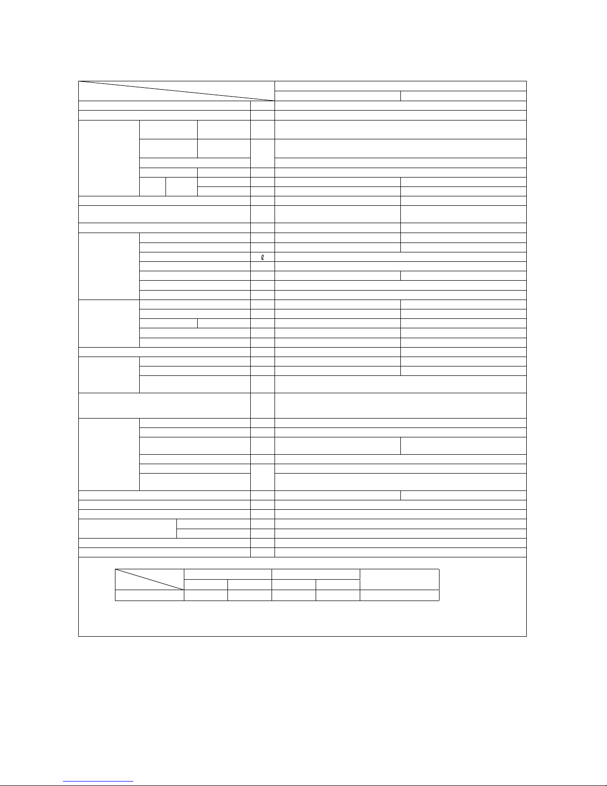
1. SPECIFICATIONS
Model
Item
SRK10YJV-S
Indoor unit SRK10YJV-S Outdoor unit SRC10YJV-S
Cooling capacity (1) W 2500 (1000 (Min.)~2700 (Max.))
Power supply 1 Phase, 220 V, 50Hz
Operation
data (1)
Power
consumption
Cooling kW 0.70 (0.21~0.88)
Running
current
Cooling
A
3.5
Inrush current 3.5
COP Cooling 3.57
Noise
level
Cooling
Sound level dB(A) Hi : 40 Me : 30 Lo : 24 49
Power level dB 56 59
Exterior dimensions (Height x Width x Depth) mm 268 x 790 x 213 540 x 780 (+62) x 290
Exterior appearance
(Munsell color)
Fine snow
(8.0Y 9.3/0.1) near equivalent
Stucco white
(4.2Y 7.5/1.1) near equivalent
Net weight kg 8.5 32
Refrigerant
equipment
Compressor type & Q'ty — RM-B5077MDE1 (Rotary type) x 1
Motor (Starting method) kW — 0.75 (Line starting)
Refrigerant oil 0.35 (DIAMOND FREEZE MA68)
Refrigerant (3) kg R410A 0.75 (Pre-Charged up to the piping length of 10m)
Heat exchanger Louver fins & inner grooved tubing M fins & inner grooved tubing
Refrigerant control Capillary tubes + Electronic expansion valve
Deice control Microcomputer control
Air handling
equipment
Fan type & Q'ty Tangential fan x 1 Propeller fan x 1
Motor W 38 24
Air flow Cooling CMM Hi : 8.0 Me : 6.2 Lo : 4.5 29.5
Fresh air intake Not possible —
Air filter, Quality / Quantity Polypropylene net (washable) x 2 —
Shock & vibration absorber — Cushion rubber (for compressor)
Operation
control
Operation switch Wireless-Remote control —
Room temperature control Microcomputer thermostat —
Operation Display
RUN : Green, TIMER : Yellow, HI POWER : Green,
3D AUTO : Orange
Safety devices
Compressor overheat protection, Overcurrent protection,
Frost protection, Serial signal error protection, Fan motor error protection,
Cooling overload protection
Installation
data
Refrigerant piping size (O.D) mm Liquid line: φ6.35 (1/4") Gas line: φ9.52 (3/8")
connecting method Flare connecting
Attached length of piping m
Liquid line : 0.4
Gas line : 0.33
—
Insulation for piping Necessary (Both sides), independent
Refrigerant line (one way) length
m
Max. 15
Vertical height difference between
outdoor unit and indoor unit
Max.10 (Outdoor unit is higher)
Max.10 (Outdoor unit is lower)
Drain hose Connectable (VP 16) —
Power cable 2m (3 Cores wih Earth)
Recommended breaker size A 16
Connection wiring
Size x Core number 1.5mm2 x 4 cores (Including earth cable)
Connecting method Terminal block (Screw fixing type)
Accessories (included)
Mounting kit
Optional parts —
Note (1) The data are measured at the following conditions.
Item
Operation
Indoor air temperature Outdoor air temperature
Standards
DB WB DB WB
Cooling 27˚C 19˚C 35˚C 24˚C ISO-T1, JIS C 9612
(2) This air-conditioner is manufactured and tested in conformity with the ISO.
(3) The operation data are applied to the 220V districts respectively.
(4) The refrigerant quantity to be charged includes the refrigerant in 10m connecting piping.
(Purging is not required even for the short piping.)
The pipe length is 7.5m.
Adapted to RoHS directive
Page 6
-
4
-
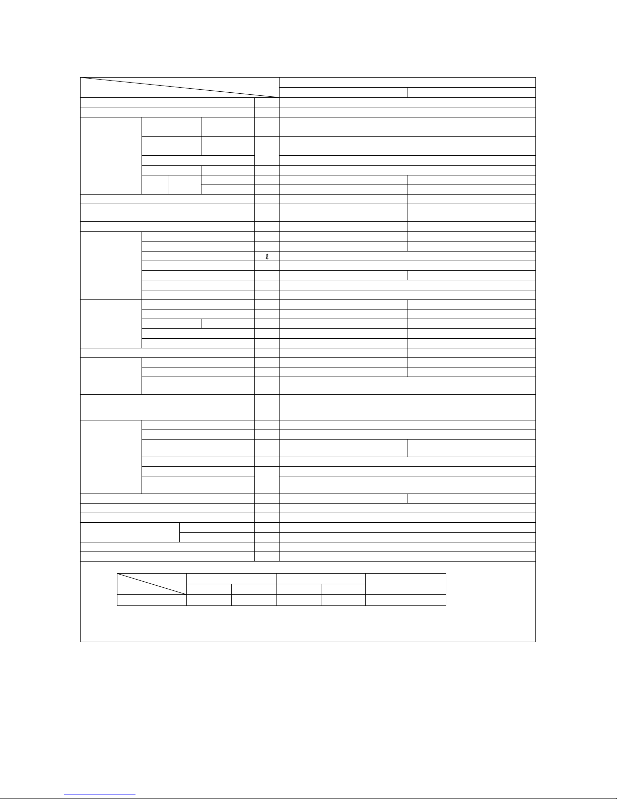
Model
Item
SRK13YJV-S
Indoor unit SRK13YJV-S Outdoor unit SRC13YJV-S
Cooling capacity (1) W 3500 (1000 (Min.)~3700 (Max.))
Power supply 1 Phase, 220 V, 50Hz
Operation
data (1)
Power
consumption
Cooling kW 0.99 (0.21~1.24)
Running
current
Cooling
A
4.7
Inrush current 4.7
COP Cooling 3.54
Noise
level
Cooling
Sound level dB(A) Hi : 46 Me : 34 Lo : 28 50
Power level dB 62 60
Exterior dimensions (Height x Width x Depth) mm 268 x 790 x 213 540 x 780 (+62) x 290
Exterior appearance
(Munsell color)
Fine snow
(8.0Y 9.3/0.1) near equivalent
Stucco white
(4.2Y 7.5/1.1) near equivalent
Net weight kg 8.5 35
Refrigerant
equipment
Compressor type & Q'ty — RM-B5077MDE1 (Rotary type) x 1
Motor (Starting method) kW — 0.90 (Line starting)
Refrigerant oil 0.35 (DIAMOND FREEZE MA68)
Refrigerant (3) kg R410A 1.05 (Pre-Charged up to the piping length of 15m)
Heat exchanger Slit fins & inner grooved tubing M fins & inner grooved tubing
Refrigerant control Capillary tubes + Electronic expansion valve
Deice control Microcomputer control
Air handling
equipment
Fan type & Q'ty Tangential fan x 1 Propeller fan x 1
Motor W 38 24
Air flow Cooling CMM Hi : 8.5 Me : 6.8 Lo : 4.6 27.8
Fresh air intake Not possible —
Air filter, Quality / Quantity Polypropylene net (washable) x 2 —
Shock & vibration absorber — Cushion rubber (for compressor)
Operation
control
Operation switch Wireless-Remote control —
Room temperature control Microcomputer thermostat —
Operation Display
RUN : Green, TIMER : Yellow, HI POWER : Green,
3D AUTO : Orange
Safety devices
Compressor overheat protection, Overcurrent protection,
Frost protection, Serial signal error protection, Fan motor error protection,
Cooling overload protection
Installation
data
Refrigerant piping size (O.D) mm Liquid line :φ6.35 (1/4") Gas line :φ9.52 (3/8")
connecting method Flare connecting
Attached length of piping m
Liquid line : 0.40
Gas line : 0.33
—
Insulation for piping Necessary (Both sides), independent
Refrigerant line (one way) length
m
Max. 15
Vertical height difference between
outdoor unit and indoor unit
Max.10 (Outdoor unit is higher)
Max.10 (Outdoor unit is lower)
Drain hose Connectable (VP 16) —
Power cable 2m (3 Cores wih Earth)
Recommended breaker size A 16
Connection wiring
Size x Core number 1.5mm2 x 4 cores (Including earth cable)
Connecting method Terminal block (Screw fixing type)
Accessories (included) Mounting kit
Optional parts —
Adapted to RoHS directive
Note (1) The data are measured at the following conditions.
Item
Operation
Indoor air temperature Outdoor air temperature
Standards
DB WB DB WB
Cooling 27˚C 19˚C 35˚C 24˚C ISO-T1 , JIS C 9612
(2) This air-conditioner is manufactured and tested in conformity with the ISO.
(3) The operation data are applied to the 220V districts respectively.
(4) The refrigerant quantity to be charged includes the refrigerant in 15m connecting piping.
(Purging is not required even for the short piping.)
The pipe length is 7.5m.
Page 7
-
5
-
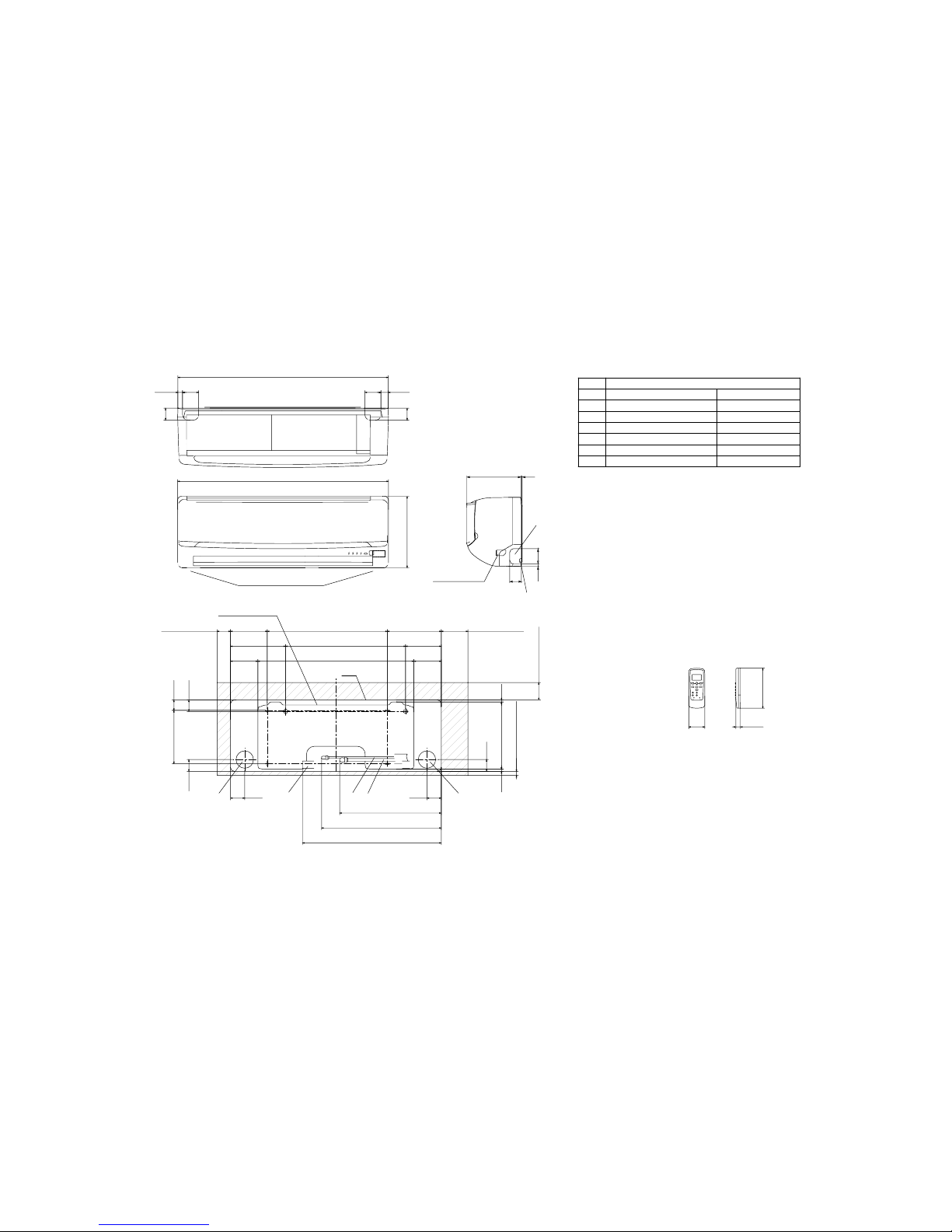
2. EXTERIOR DIMENSIONS
(1) Indoor units
Models SRK10YJV-S, 13YJV-S
Wireless remote controller
Outlet for down piping
㧔Refer to the above view㧕
Space for installation and service when viewing from the front
D A
B
E
C
Hole on wall for right rear piping
Hole on wall for left rear piping
Gas piping
Outlet for wiring
Drain hose
Liquid piping
F
E
C
D
B
Symbol
A
㧔Ǿ65㧕
VP16
Ǿ6.35㧔1㧛4"㧕㧔Flare㧕
Content
㧔Ǿ65㧕
Ǿ9.52㧔3㧛8"㧕㧔Flare㧕
Outlet for piping㧔on both side㧕
G
Note㧔1㧕The model name label is attached
ޓޓޓon the underside of the panel.
60
150
17.3
788
2760
45
60
45
790
268
17.5
200
39.3
43.244.5
102.5 585 102.5
206.5 450 133.5
138 450 202
44.5
7.5252.28.3
㧔Service space㧕
65
㧔Service space㧕
15
50
㧔
Service space
㧕
100
㧔Service space㧕
53.5
380.6
448.6
520
53.5
Installation plate
Unit
Unit:mm
Terminal block
G
F
9
213 3
45
60
Page 8

-
6
-
(2) Outdoor units
Models SRC10YJV-S, 13YJV-S
Notes
㧔1㧕 It must not be surrounded by walls on the four sides.
㧔2㧕 The unit must be fixed with anchor bolts. An anchor bolt must not
protrude more the 15mm.
㧔3㧕 Where the unit is subject to strong winds, lay it in such
a direction that the blower outlet faces perpendicularly
to the dominant wind direction.
㧔4㧕 Leave 1m or more space above the unit.
㧔5㧕 A wall in front of the blower outlet must not exceed the units height.
㧔6㧕 The model name label is attached on the lower right comer of the front panel.
L4
L3
L1
Intake
Service
space
Intake
Outlet
Minimum installation space
L2
L2
L3
L4
L1
100
100
250
Open
㧵 㧵㧵
Open
250
80
280
㧵㧵㧵
280
Open
80
75
Examples of
Dimensions
installation
㧵㨂
180
Open
80
Open
Ǿ9.52㧔3㧛8"㧕㧔Flare㧕
Content
C Pipe㧛cable draw-out hole
D
E Anchor bolt hole
Drain discharge hole
Symbol
B
A Service valve connection㧔gas side㧕
M10 × 4places
Ǿ20 × 2places
Service valve connection㧔liquid side㧕
Ǿ6.35㧔1㧛4"㧕㧔Flare㧕
Unit:mm
A
C
Terminal block
B
40°
40°
33.5
138.4
97.7
15.8
540
290
42.5
69.4
63.4
390.6
390.6
111.6 510
158.4
12
50.6
17.9
780 61.9
312.5
351.6
14.8 24.3
D
E
Page 9
-
7
-
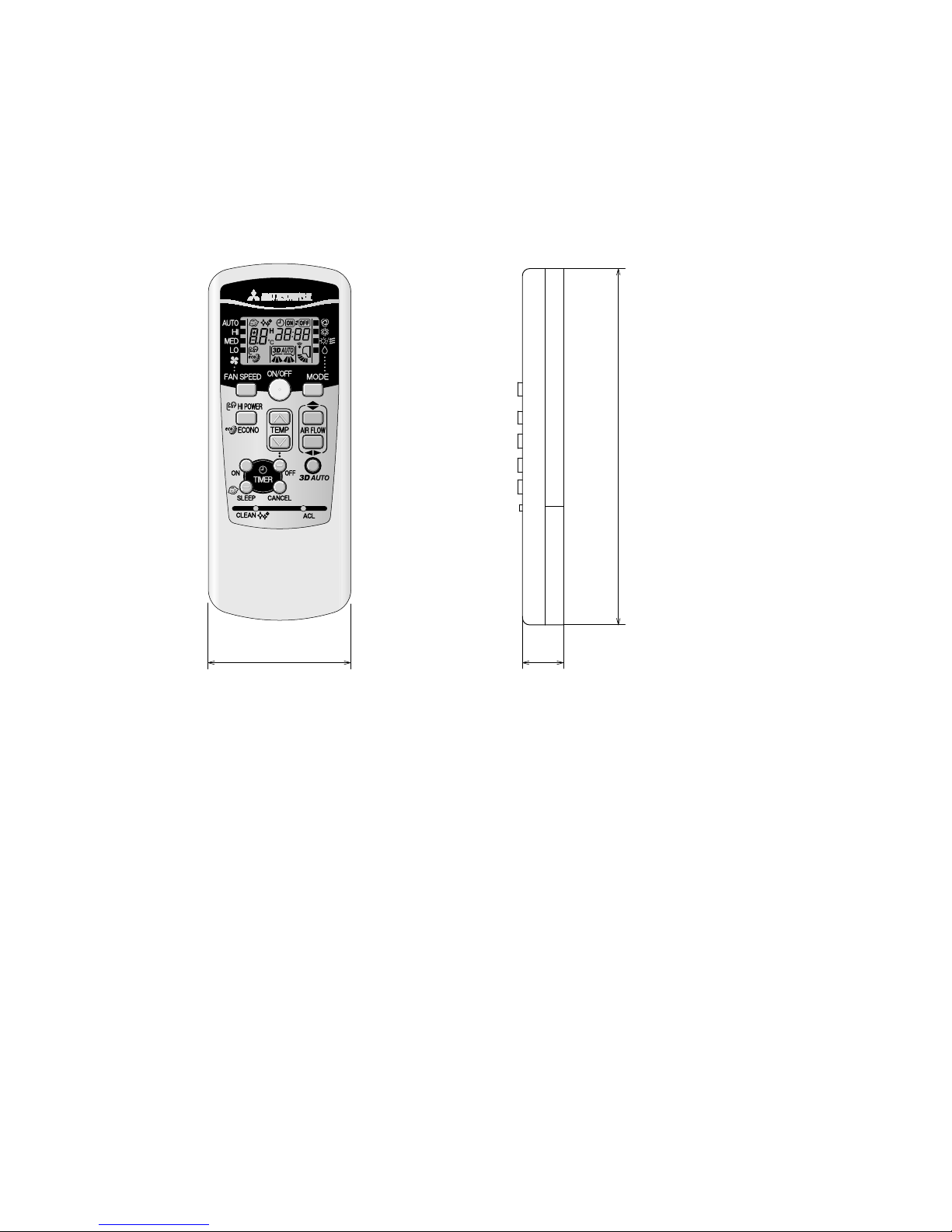
(3) Wireless remote controller
Unit: mm
60
17.3
150
Page 10
-
8
-
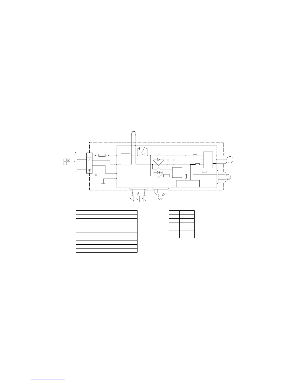
3. ELECTRICAL WIRING
(1) Indoor units
Models SRK10YJV-S, 13YJV-S
G
J
R-AMP
WIRELESS
DISPLAY
N
CNGCNE
250V 3.15A
CNU
52C
52C-3
52C-4
BACK UP SW
U
M
CNF
FM
HD
F
Va
DS
T
※
CNX
5
M
CNY
5
M
LM1 LM2
CNM
5
M
SM
Blue
BlackBK
Red
BL
RD
WhiteWH
Yellow/Green
Y/G
ColorMark
Heat exch. sensor
Fan motor
Room temp. sensor
Flap motor
Diode stackDS
FuseF
Connector
CNE-CNU
FM
Terminal blockT
Description
Item
VaristorVa
SM
Louver motor
LM1,2
ThI
Th2
YellowY
Humidity sensor
HD
BrownBR
Light blueLB
BR
Y/G
RD
Y
WH
Y/G
RD
BK
BOX
CONTROL
3
2/N
WH
6
TO OUTDOOR UNIT
1
BOARD
PRINTED CIRCUIT
~220V 50Hz
POWER SOURCE
BR
LB
Y/G
BK
1 3 4 5
RDBKBL
EXCHANGER
HEAT
WH
8 2 2 2
t゜
※SRK13 MODELS ONLY
ThI Th2
t゜
Page 11
-
9
-
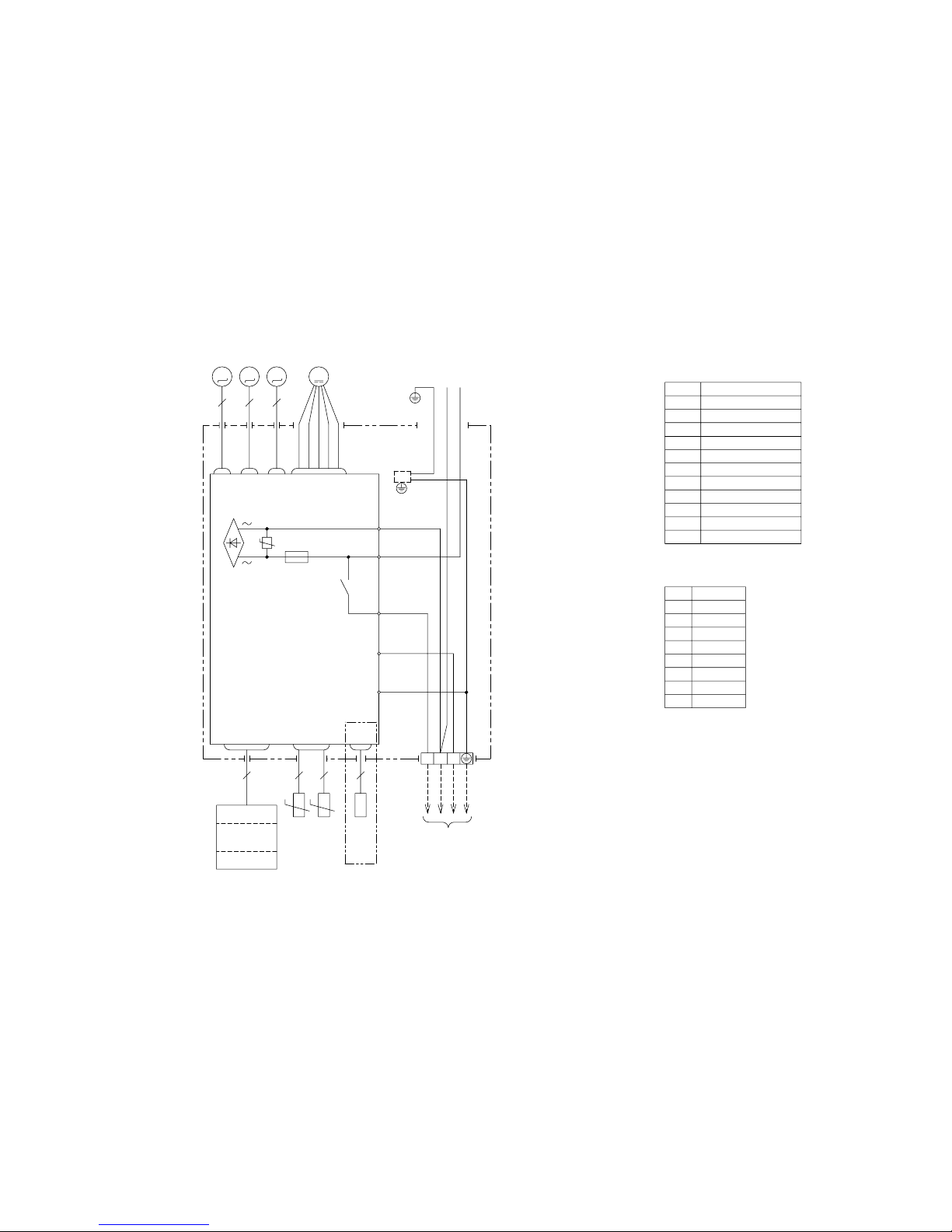
(2) Outdoor units
Models SRC10YJV-S, 13YJV-S
3
1
2
[
]
N
(BK)
C-2
G1
(RD)
(Y/G)
S.IN
(WH)
R.IN
(BK)
(WH)
(RD)
PWB ASSY
250V 20A
F2
F3 250V 1A
++
F4
250V 10A
F1
250V 2A
CIRCUIT
PAM
SWITCHING POWER
CIRCUIT
NW
NV
NU
P
W
V
U
TRANSISTOR
POWER
W
V
U
FILTER
NOISE
CNTH
CNEEV
CNFAN
M
M
3~
250V 15A
(Y/G)
T1
T2
(OR)
(Y)
M
t゜
TH1TH2 TH3
EEV
FMo
CM
t゜ t゜
t゜
L
TERMINAL
N
1
3
2
BLOCK
T
TO INDOOR UNIT
POWER WIRES
SIGNAL WIRE
POWER SOURCE
~220V 50Hz
Color
RD
Mark
OrangeOR
Yellow/Green
Y/G
BlackBK
YellowY
WhiteWH
Red
DescriptionItem
Connector
Electric expansion valve(coil)EEV
Fan motorFMo
ReactorL
Terminal blockT
Compressor motorCM
Heat exchanger sensor(outdoor unit)TH1
Outdoor air temp.sensorTH2
TH3 Discharge pipe temp.sensor
CNTH
CNEE
Page 12
-
10
-
'09•SRK-DB-087D
5 PIPING SYSTEM
Models SRK20ZJ-S, 25ZJ-S
Model SRK35ZJ-S
Humidity
sensor
(HD)
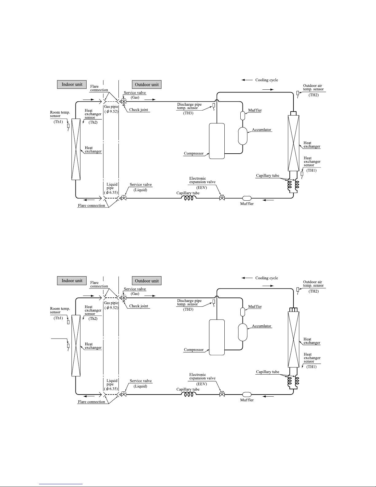
4. PIPING SYSTEM
Model SRK10YJV-S
Model SRK13YJV-S
Page 13
-
11
-
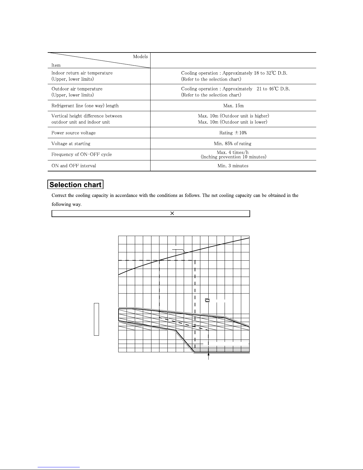
5. RANGE OF USAGE & LIMITATIONS
SRK10YJV-S,13YJV-S
Net capacity = Capacity shown on specification Correction factors as follows.
(1) Coefficient of cooling capacity in relation to temperatures
Cooling
2220181614
0.6
0.7
0.8
0.9
1.0
1.2
1.1
1.3
0
-5
-10
-15
Applicable range
Depends on installed situation
24
26
20
25
30
35
40
46
ISO-T1 Standard Condition
Cooling operation
Outdoor air D.B.
temperature
(°C D. B.)
Coefficient of cooling
capacity in
relation to temperature
Indoor air W.B. temperature °C W.B.
+
Page 14
-
12
-
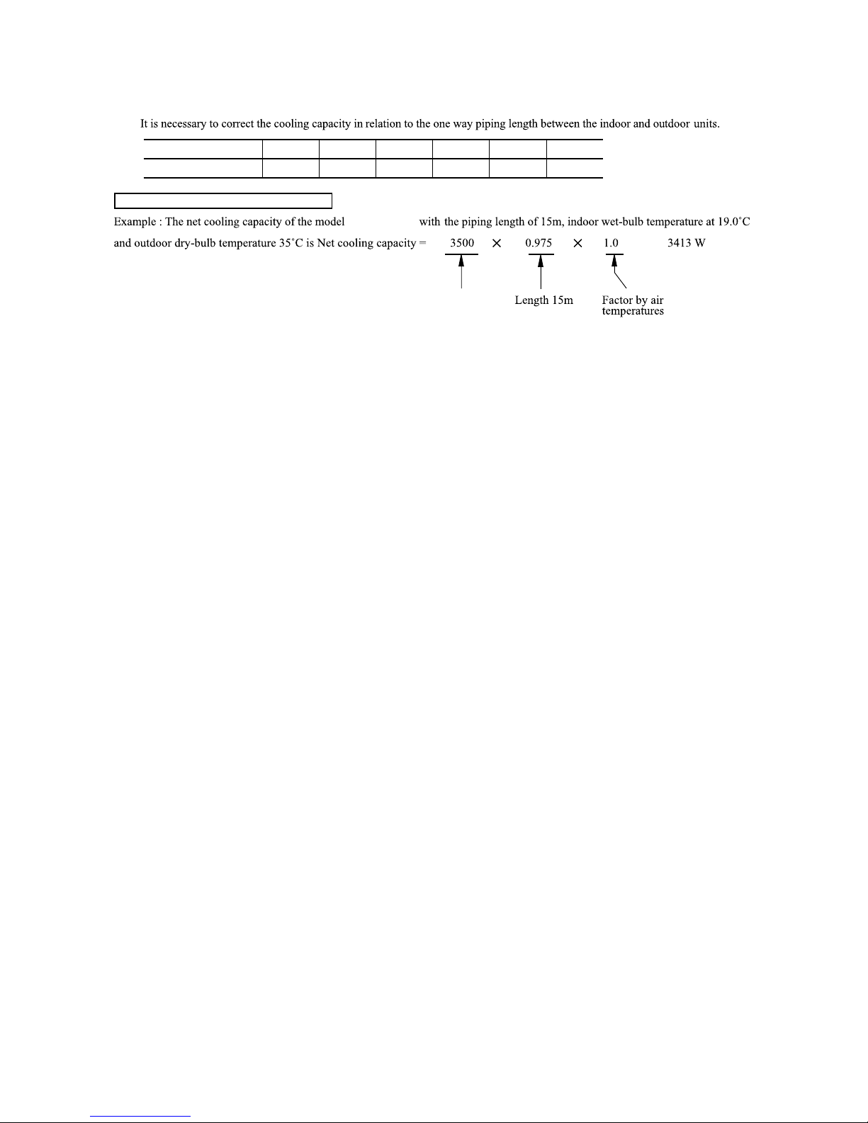
(2) Correction of cooling capacity in relation to one way length of refrigerant piping
How to obtain the cooling capacity
=
Piping length [m]
Cooling
7
1.0
10
0.99
15
0.975
20
0.965
25
0.95
30
0.935
SRK13YJV-S
SRK13YJV-S
Page 15
-
13
-
6. APPLICATION DATA
Safety precautions
• When install the unit, be sure to check whether the selection of installation place, power supply specifications, usage limitation (piping
length, height differences between in door and outdoor un its, power supply voltage and etc.) and installation spaces.
• We recommend you to read this “SAFETY PRECAUTIONS” carefully before the installation work in order to gain full advantage of the functions of the unit and to avoid malfunction due to mishandling.
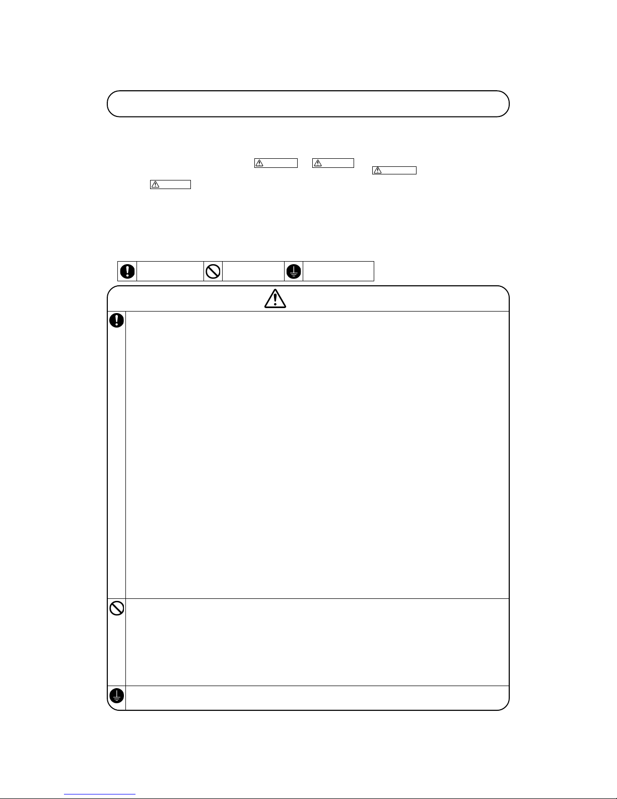
• The precautions described below are divided into
WARNING and CAUTION . The matters with possibilities leading to serious conse-
quences such as death or serious personal injury due to erroneous handling are listed in the
WARNING and the matters with possibilities
leading to personal injury or damage of the unit due to erroneous handling including probability leading to serious consequences in some cases
are listed in
CAUTION . These are very important precautions for safety. Be sure to observe all of them without fail.
• Be sure to confirm no anomaly on the equipment by commissioning after completed installation and explain the operating methods as well as the
maintenance methods of this equipment to the user according to the owner’s manual.
• Keep the installation manual together with owner’s manual at a place where any user can read at any time. Moreover if necessary, ask to hand
them to a new user.
• For installing qualified personnel, take precautions in respect to themselves by using suitable protective clothing, groves, etc., and then perform
the installation works.
• Please pay attention not to fall down the tools, etc. when installing the unit at the high position.
• If unusual noise can be heard during operation, consult the dealer.
• Symbols which appear frequently in the text have the following meaning:
Observe instructions
with great care
Strictly prohibited Provide proper earthing
WARNING
• I nstallatio n must be carried o ut by the qualified installer.
If you install the sys tem by yourself, it may cause ser ious trouble su ch as
water le aks, ele ctric sho cks, fire and per sonal in jury, as a result of a system
malfunct ion.
• I nstall the system i n full acc ordance w ith the in struction manual.
Incorrec t installat ion may cau se bursts, personal in jury, wate r leaks, el ectric
shocks an d fire.
• B e sure to use only for househ old and r esidence.
If t his applian ce is inst alled in inferio r env ironment such as mach ine s hop
and etc. , it can c ause malf unction.
•
Use the orig inal accesso ries and the sp ecified com ponents for in stallation.
If parts o ther than t hose presc ribed by us are used, I t may cause water leak s,
electric shocks, f ire and pe rsonal injury.
• I nstall the unit in a location with goo d support.
Unsuitab le installat ion locatio ns can cause th e unit to fall and cause mate rial
damage a nd persona l injury.
• E nsure th e unit is stable w hen installed, so t hat it can withstand earthquakes a nd strong winds.
Unsuitab le installat ion locatio ns can cause th e unit to fall and cause mate rial
damage a nd persona l injury.
• V entilate the worki ng area well in the even t of ref rigerant leakage d uring insta llation.
If the re frigerant comes into contact with nak ed flames, poisonous gas is
produced .
• W hen install ing in smal l rooms, ta ke preventi on measure s not to exc eed
the dens ity limit of refrige rant in the even t of leaka ge.
Consult the expe rt ab out p revention me asures. If the density o f ref rigerant
exceeds the limit in the event of leakage , lac k of oxygen can occu r, whi ch
can caus e serious accidents .
•
After comp leted insta llation, ch eck that no ref rigerant le aks from the s ystem.
If refrigerant leaks into the room a nd comes into co ntact with a n o ven or
other ho t surface, poisonou s gas is p roduced.
• U se the pre scribed p ipes, flar e nuts an d tools fo r R410A.
Using ex isting parts ( for R22 or R407C) can ca use the unit fail ure and serious acci dents due to burst o f the ref rigerant c ircuit.
• T ighten the flare nu t by torqu e wrench w ith specified me thod.
If the flare nut w ere tightened with excess torque, this may cause bu rst and
refriger ant leakag e after a long peri od.
• D o not open th e operat ion val ves for liquid line and gas lin e until completed r efrigerant piping w ork, air t ightness t est and evacuati on.
If the c ompressor is operated in s tate of o pening operation valves before
complete d connec tion of refrigerant pi ping work, ai r can be sucke d into refrigeran t circuit, whi ch can cause bust or personal inj ury due to anomal ously
high pre ssure in t he refrig erant.
• D o not put th e drainage pipe di rectly int o drainage channels w here poisonous g ases such as sulphid e gas can occur.
Poisonou s gases will flo w into the room through drai nage pipe and s eriously
affect t he user’s health an d safety.
• E nsure t hat no air enters in the refriger ant cir cuit w hen the unit is installed a nd removed.
If a ir en ters in the refr igerant circuit, the pr essure in the refrigerant circuit
becomes too high, which can cause bur st and pe rsonal inj ury.
• D o not proc essing, splice th e po wer c ord, or sh are a socket with other
power plu gs.
This may cause fire or electric shock due to defect ing contact, de fecting insulation and over- current e tc.
• T he el ectrical installation must be carried out by the qualifi ed el ectrician in accor dance with “th e n orm for electrical work” and “na tional
wiring regulation”, and the s ystem must be conne cted t o the dedicated
circuit.
Power s upply with in sufficien t capaci ty and incorrect fun ction do ne by improper w ork can ca use elect ric shocks and fire .
• B e sure to shut off the power before st arting ele ctrical work.
Failure t o shut off the power can cause electric s hocks, uni t failure or incorrect fun ction of e quipment.
• B e s ure to use the cab les confo rmed to sa fety stan dard and cab le
ampacity for power distribut ion work.
Unconfor mable cables can cause electr ic leak, anomal ous heat production or
fire.
• T his app liance m ust be conne cted to main power suppl y by means of a
circuit br eaker or switc h (fuse:16A ) with a contac t separation of at least
3mm.
• W hen p lugg ing t his ap pli anc e, a p lug conf ormi ng to t he no rm
IEC60884 -1 must be used.
• U se the pre scribed cables for electrical connection, tighten the cables
securely i n terminal block a nd relieve the cabl es correctly to pre vent
overload ing the te rminal bl ocks.
Loose conn ections or ca ble mountin gs can cause a nomalous hea t production
or fire.
• A rrange the w iring in the co ntrol box so t hat it canno t be pushed up
further into the b ox. Instal l the service pa nel correc tly.
Incorrec t installa tion may result in overheatin g and fire.
• B e sure to fix up the service panels.
Incorrec t fixing can cause e lectric shocks or fi re due to intrusion of dust or
water.
• B e sure to switch off the power supply in the event of installation , inspection or servicing.
If the powe r s upply is not shut off, the re is a risk of el ectric shocks, unit
failure or persona l injury due to the unexpect ed start o f fan.
• S top the comp ressor before disconnecting refrigeran t pipes in case of
pump dow n operatio n.
If disconne cting refri gerant pipes in state of openin g operation valves before
compress or sto pping, air can b e suck ed, wh ich ca n cause b urst o r pers onal
injury d ue to anom alously h igh pressu re in the refrigera nt circui t
• O nly use presc ribed optio nal parts. T he installa tion must be c arried out
by the q ualified i nstaller.
If you ins tall the sys tem by your self, it can c ause serious trouble such as
water le aks, elect ric shock s, fire.
• D o not bundling, win ding or processing f or the power cord. Or, do not
deformin g the powe r plug du e to tread it.
This may cause fir e or heat ing.
• D o not ven t R410A i nto the a tmosphere : R410A is a fluorinated greenhouse g as, cove red by the Kyoto Pro tocol wi th Globa l Warming Pot ential (GWP )=1975.
• D o not run the unit with remov ed panels or protec tions.
Touching rotati ng equi pments, hot surfaces or high vo ltage p arts ca n cause
personal injury du e to entra pment, burn or e lectric sh ocks.
•
Do not perfor m any change of prot ective devic e itself or it s setup condit ion.
The forced ope ration by short- circuitin g protective dev ice of pressure switch
and temp erature c ontroller or the use of no n specifi ed compon ent can cause
fire or burst.
• C arry out t he electr ical work for groun d lead wit h care.
Do not co nnect the ground le ad to the gas line, water lin e, lightni ng conduc tor or tel ephone lin e’s ground lead. Incorrect groundin g can caus e unit fa ults such
as elect ric shocks due to sh ort-circu iting.
Page 16
-
14
-
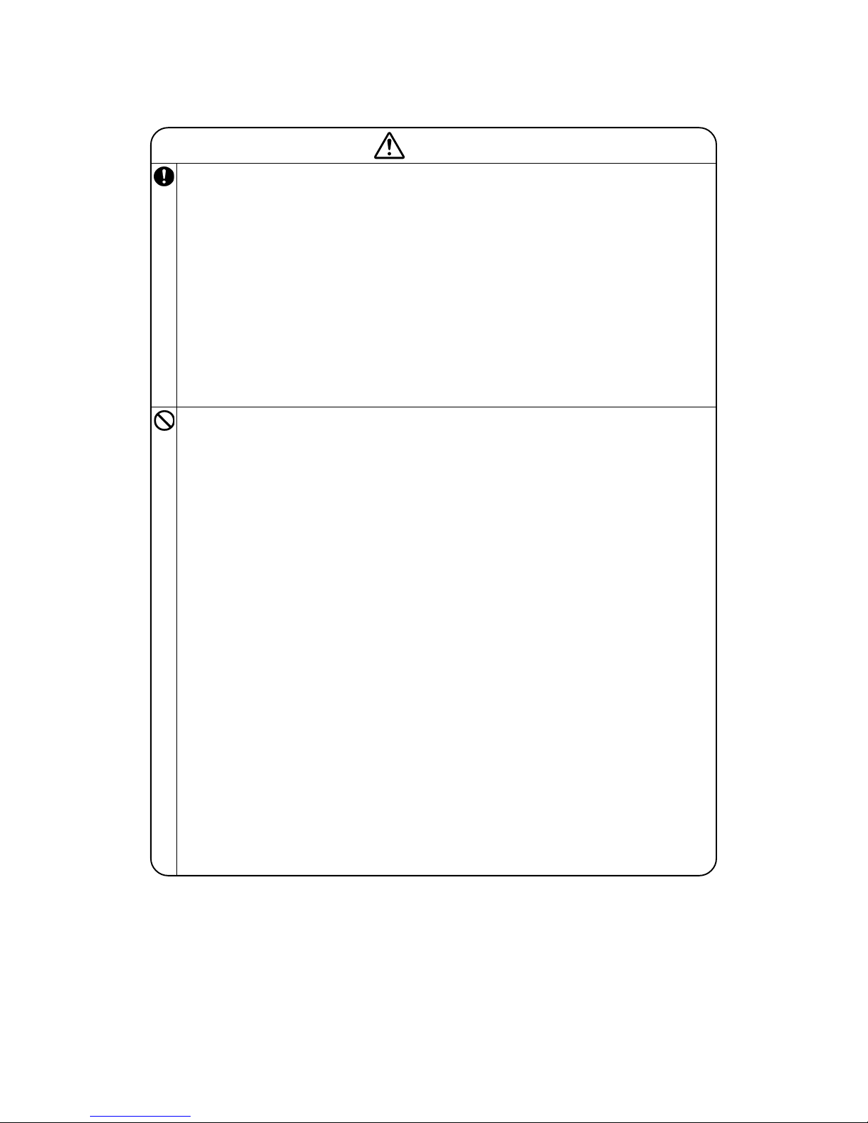
CAUTION
• U se the cir cuit brea ker with s ufficient breaking capacity.
If the breaker does not have sufficient breaking capacit y, it can cause the unit
malfunct ion and fi re.
• E arth leaka ge breake r must be installed .
If the ea rth leakage brea ker is not installe d, it can cause elec tric shocks.
• I nstall isolator o r dis connect switch on the pow er su pply wiring in accordance with the local code s and regulation s.
• B e su re to install indo or unit proper ly a ccording to the instruc tion
manual i n order to run off the draina ge smooth ly.
Improper installa tion of i ndoor uni t can ca use dropp ing water into the room
and dama ging perso nal prope rty.
• I nstall the draina ge pi pe to run off drai nage securely according to the
installa tion manua l.
Incorrec t installa tion of the dra inage pipe can caus e dropping water into the
room and damaging personal property.
• B e s ure to insta ll the drainage pipe with de scending slope of 1/100 or
more, an d not to m ake traps and air-b leedings.
Check if the drai nage runs off secu rely during comm issioning and ensure the
space fo r inspecti on and ma intenance.
• A fter maintenanc e, all w iring, wiring ties and the li ke, sh ould be returned t o their o riginal s tate and wiring route, a nd the ne cessary c learance fro m all meta l parts s hould be s ecured.
• S ecure a space fo r install ation, i nspection and maintenanc e specifi ed in
the manu al.
Insuffic ient space can resul t in accident such as per sonal injury due to falling
from the installat ion place .
• T ake care w hen carry ing the un it by hand .
If th e unit weigh ts mor e than 20kg, it must be carried by two o r more persons. Do not carry by the plasti c str aps, a lways use the carry handl e whe n
carrying th e u nit by hand. Us e g loves to mini mize the risk of cuts by t he
aluminum fins.
• D ispose of any packi ng materia ls correc tly.
Any remaining packing materials can c ause personal injury as it contains
nails and woo d. And to avoid dan ger of suffoca tion, be sure to kee p the plastic wrap per away f rom child ren and to dispose after tear it up.
• F or installation work, be careful not to g et injured with t he heat e xchanger, piping fl are porti on or scre ws etc.
• B e sure to insulate t he refrig erant pipe s so as no t to cond ense the a mbient air m oisture on them.
Insuffic ient insulation can cause c ondensatio n, wh ich c an lead to moisture
damage o n the ceil ing, floo r, furnitu re and an y other va luables.
• W hen pe rform the air conditioner operation (cool ing o r dry ing op eration) in which ventil ator is installed in the room. I n this case, using the
air conditio ner in parallel with the vent ilator, there is the possibility that
drain water may bac kflow in accorda nce w ith the room lapse into the
negative pressur e status . Theref ore, set up th e openin g port such as incorporat e the air into the room that may app ropriate to ventilation (For
example; Open the door a little). I n addition, just as above , so set up the
opening por t if the room lapse in to negative pre ssure status due to register of t he wind fo r the hig h rise apa rtment et c.
• D o not inst all the u nit in the locations listed below.
• L ocations where carb on fiber, metal pow der or an y powder i s floatin g.
• L ocations where any substances that can affect the unit such as s ulphide
gas, chl oride gas, acid and alkaline can occur .
• V ehicles a nd ships.
• L ocations where cosm etic or special sprays are often us ed.
• L ocations with direct exposure of oil mist and steam such as kit chen and
machine plant.
• L ocations where any mach ines whic h generat e high frequency harmonics
are used .
• L ocations with salty atmospheres suc h as coast lines.
• L ocations wi th heavy snow (If installed, be sure to provide base flame and
snow hoo d mentione d in the manual).
• L ocations where the unit is exposed to chimney smoke.
• L ocations at high al titude (more tha n 1000m hi gh).
• L ocations with ammon ic atmospheres.
• L ocations where heat radiation from other heat source c an affect the unit.
• L ocations without go od air circulati on.
• L ocations with any obstac les which can pre vent inle t and ou tlet air of the
unit.
• L ocations where short circ uit of a ir c an o ccur (in case of mul tiple units
installa tion).
• L ocations where stro ng air bl ows agains t the air outlet of outdoor unit.
It ca n cause remar kable decrease in performa nce, co rrosion and damage of
componen ts, malfun ction and fire.
• D o no t i nstall the ind oor unit in the locations listed below (Be sure to
instal l the indoor unit according to the installat ion m anual for each
model be cause each indoor un it has each limi tation).
• L ocations with any obstac les which can pre vent inle t and ou tlet air of the
unit.
• L ocations w here vibra tion can be amplified due to insu fficient s trength of
structur e.
• L ocations where the infrared receiver is exposed to the dir ect sun light or
the stro ng light b eam (in c ase of the infrared specifica tion unit ).
• L ocations where an eq uipment affected by high ha rmonics is plac ed (TV
set or r adio recei ver is pl aced withi n 1m).
• L ocations where drai nage cann ot run off safely.
It can a ffect perf ormance o r function and etc.
• D o not inst all the o utdoor uni t in the l ocations listed bel ow.
• L ocations w here disch arged hot a ir or opera ting sound of the outd oor unit
can both er neighbo rhood.
• L ocations where outl et air of the outdo or unit b lows direc tly to pl ants.
• L ocations whe re vibration can be amplified and transmitte d due to insuffi-
cient st rength of structure .
• L ocations where vibra tion an d opera tion s ound ge nerated by the out door
unit can affect se riously ( on the wal l or at t he place n ear bed r oom).
• L ocations where an eq uipment affected by high ha rmonics is plac ed (TV
set or r adio recei ver is pl aced withi n 1m).
• L ocations where drai nage cann ot run off safely.
It can a ffect surr ounding e nvironment and caus e a claim.
• D o not install the unit near the l ocation where l eakage of combus tible
gases ca n occur.
If leake d gases ac cumulate around the unit, it can cause fire.
• D o not inst all t he un it wh ere c orrosive gas (suc h as sulfurous acid gas
etc.) or comb ustible gas (s uch as thinner and petroleum gases) can accu mulate or co llect, or whe re volatile combustibl e substance s are handled .
Corrosiv e gas can cause corrosion of heat e xchanger, breakage of plastic
parts an d etc. And combusti ble gas ca n cause f ire.
• D o not use the indo or unit at the place whe re water splashes may oc cur
such as i n laundries.
Since the indoor un it is not w aterproof, it can cau se electri c shocks a nd fire.
• D o not install nor use the s ystem c lose to the equipment tha t gener ates
electrom agnetic fi elds or h igh freque ncy harmon ics.
Equipmen t such as inverters , standby generators, medical high frequency
equipmen ts a nd t elecommun ication equipments can aff ect the system , an d
cause malfunc tions and breakdowns. The system can also affect medical
equipmen t a nd telecommun ication equipment, and obstruct its function or
cause jam ming.
• D o not pla ce any va riables w hich will be damag ed by get ting wet under
the indo or unit.
When th e relati ve humid ity is higher t han 80% or drainage pipe is clogged,
condensa tion or drainage water can drop and it can cause the damage of valuables.
• D o not inst all the r emote cont rol at the direct sunlight .
It can c ause malfu nction or deformati on of the remote co ntrol.
• D o not use the unit fo r sp ecial purposes s uch a s st oring foods, cool ing
precisio n instrume nts and p reservatio n of anima ls, plants or ar t.
It can c ause the d amage of the items.
• D o not install the outdoor un it in a location where in sects and small animals can inhabit.
Insects and small anim als ca n ent er the elec tric p arts and ca use d amage or
fire. In struct the user to keep the s urroundin gs clean.
• D o not use the base flam e for outdoor unit which is corroded or da maged due to long p eriods of operation .
Using an old an d d amage base fla me can cause the un it falling down and
cause per sonal injury.
• D o not use any materials other than a fuse with t he correct r ating in the
location where fus es are to be used.
Connecti ng the circ uit with co pper wire or other metal thread can cause unit
failure and fire.
• D o not touc h any but tons with wet hands .
It can ca use electric sho cks.
• D o not t ouch any refr igerant pipes wi th your hands when the syst em is
in opera tion.
During operation the refri gerant pipes be come extremely h ot or extremely
cold depe nding the o perating c ondition, a nd it can ca use burn injury or frost
injury.
• D o not touc h the suc tion or al uminum fin on the outdoor unit.
This may cause inj ury.
• D o not put anything on the out door unit and opera ting unit .
This may cause dam age the o bjects or injury du e to falli ng to the object.
Page 17
-
15
-
Necessary tools for the installation work
1 Plus headed driver (Phillips screwdriver)
2 Knife
3 Saw
4 Tape measure
5 Hammer
6 Spanner wrench
7 Torque wrench
8 Hole core drill (65mm in diameter)
9 Wrench key (Hexagon)
[4m/m]
10 Vacuum pump
11
Vacuum pump adapter
(Anti-reverse flow type)
12 Gauge manifold
13 Change hose
14 Flaring tool set
15 Gas leak detector
16
Gauge for projection adjustment (Used when flare
is made by using conventional flare tool)
17 Pipe bender
( )
Standard accessories
(Installation kit) Q'ty
Accessories for indoor unit
1
Installation board
1
(Attached to the rear of the indoor unit)
2 Wireless remote control 1
3 Remote contorol holder 1
4
Tapping screws
5
(for installation board 4dia. by 25mm)
5
Wood screw
2
(for remote contorol switch holder 3.5dia. by 16mm)
6
Baterry [R03 (AAA, Micro) 1.5V]
2
7 Air-cleaning filters 2
8
Filter holders
2
(Attached to the front panel of the indoor unit)
Option parts Q'ty
a Sealing plate 1
b Sleeve 1
c Inclination plate 1
d Putty 1
e Drain hose (extention hose) 1
f
Piping cover (for insulation of
1
connection piping)
1 A place where good air circulation can be obtained and where rain,
snow or sunshine will not directly strike the unit.
2 A place where discharged hot air or unit’s operating sound will not
be a nuisance to the neighborhood.
3 A place where servicing space can be secured.
4 A place where vibration will not be enlarged.
*Avoid installing in the following places.
•A place near the bedroom and the like, so that the operation
noise will cause no trouble.
•
A place where there is possibility of flammable gas leakage.
•A place exposed to strong wind.
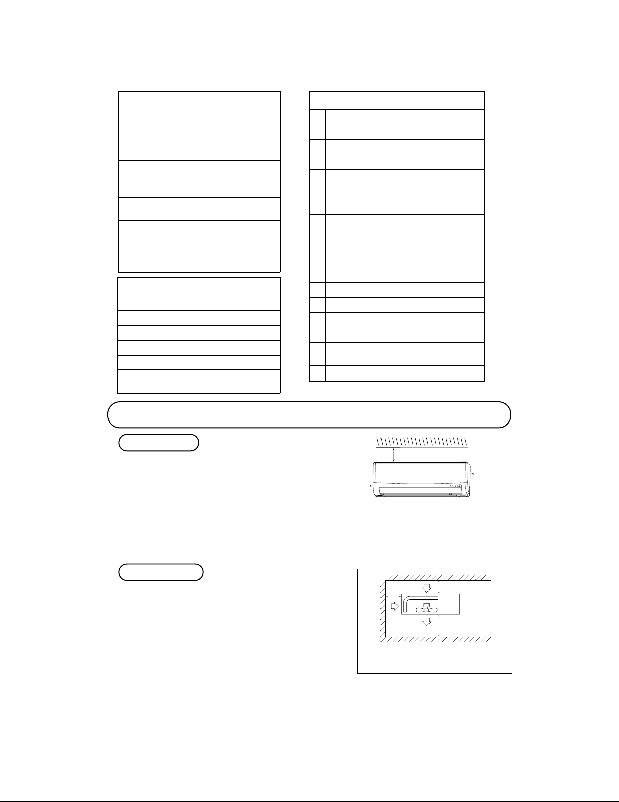
5 Blowing out port and suction port on the back side of the unit can
be installed at a distance of 10cm from walls.
In case the barrier is 1.2m or above in height, or is overhead, the
sufficient space between the unit and wall shall be secured.
6 When the unit is installed, the space of the following dimension
and above shall be secured.
OUTDOOR UNIT
Note (1) If the wall is higher than 1.2 m or a ceiling is
present, distances larger than indicated in the
above table must be provided.
Selection of installation location
1 Where there is no obstructions to the air flow and where the
cooled air can be evenly distributed.
2 A solid place where the unit or the wall will not vibrate.
3 A place where there will be enough space for servicing. (Where
space mentioned right can be secured)
4 Where wiring and the piping work will be easy to conduct.
5 The place where receiving part is not exposed to the direct rays
of the sun or the strong rays of the street lighting.
6 A place where it can be easily drained.
7 A place separated at least 1m away from the television or the
radio.
(To prevent interfence to images and sounds.)
INDOOR UNIT
6.5 cm
5 cm
10 cm
Left
side
14.0 ~ 6 2.0N · m
(1.4 ~ 6 .2kgf · m)
( )
Designed specifica lly
for R410 A
( )
Designed specifica lly
for R410 A
( )
Designed specifica lly
for R410 A
( )
Designed specifica lly
for R410 A
( )
Designed specifica lly
for R410 A
60 cm MIN
Air intake
10 cm MIN
10 cm
MIN
Air outlet
Air
intake
No obstacles
(Service space
for electrical
parts)
Right
side
( )
Page 18

-
16
-
Installation of indoor unit
Installation of installation board
• Adjustment of the installation board in the horizontal
direction is to be conducted with five screws in a
temporary tightened state.
• Adjust so that board will be level by turning the board
with the standard hole as the center.
Standard hole
Look for the inside wall structures (Intersediate support or
pillar and firaly install the unit after level surface has been
checked.)
Mating mark for level surface
450
INSTALLATION SPACE (INDOOR UNIT) (FRONT VIEW)
Unit : mm
Piping hole( 65) Piping hole( 65)
Installation board
Indoor unit
53.5
Piping for Gas 380.6
Piping for Liquid 448.6
Drain hose 520( 16)
53.5
Space *
for service
Space
for service
44.5
252.2
7.5
8.3
Space for
service
50
Space for
service
100
102.5
585
102.5
133.5
450206.5
202450138
44.5
43.2
39.3
200
65
15
Limitations for one way piping length and vertical height difference
Model
SRK10YJV-S
Item
SRK13YJV-S
Total one way piping length (R) Max. 15 m
Vertical height difference (h) Max. 10 m
r
h
Drilling of holes and fixture sleeve (Option parts)
(Insertin g sleeve)
Note (1) Drill a hole with incline of 5 degree from
indoor si de to outd oor side.
Indoor side Outdoor side
Cut off the sleeve
col lar in cas e of
dr aw in g p ipin g
out to re ar.
Cut off the sleeve
collar that can be
seen from beneath
the unit.
Wall thic kness
+ 1.5 cm
Indoor side Outdoor side
Turn t o
tighten
Paste
View of sleeve when installed
In cl ined
flange
Seal ing
plate
Sleeve
Indoor side Outdoor side
(*Sleeve + *Incline d + *Seali ng plate)
Drill a hole with 65 whole core drill Adjusting sleeve length
Install the sleeve
*Leave e xtra space on the r ight side to enable removal o f the lid screw.
Page 19
-
17
-
Preparation of indoor unit
Pipe
Drain hose
1. Remove the drain hose. 2. Remove the drain cap. 3. Insert the drain cap. 4. Connect the drain hose.
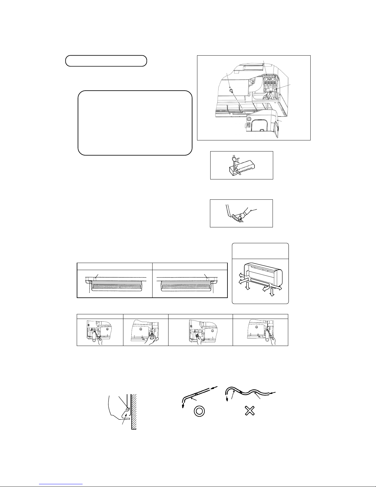
1 Mounting of connecting wires
a Remove the lid.
b Remove the wiring clamp.
c Connect the connecting wire securely to the terminal block.
Use cable for interconnection wiring to avoid loosening of the
wires.
CENELEC code for cables Required field cables.
H05RNR3G1.5 (Example) or 245IEC57
H Harmonized cable type
05 300/500 volts
R Natural-and/or synth. rubber wire insulation
N Polychloroprene rubber conductors insulation
R Standed core
4or5 Number of conductors
G One conductor of the cables is the earth conductor (yel-
low/green)
1.5 Section of copper wire (mm
2
)
• Connect the connection wire securely to the terminal block.
If the wire is not affixed completely, contact will be poor,
and it is dangerous as the terminal block may heat up and
catch fire.
• Take care not to confuse the terminal numbers for indoor
and outdoor connections.
• Earth lead wire shall be longer than the other lead wires for
the electrical safety in case of the slipping out of the cord
from the anchorage.
• The earth line of power cord must be properly earthed.
• Affix the connection wire using the wiring clamp.
d Fix the connecting wire by wiring clamp.
e Attach the lid.
f Close the air inlet panel.
2 Shaping the pipe
3 Taping of the exterior
• Hold the botto m of the pipe and change it s directio n before
stretchi ng it and shaping it .
• Tape only t he portio n that run s through the wall.
Always t ape the cr ossover wi res with the pip e.
4 Cautions when piping from the left and the rear center of the unit
[ Top View ]
• Remove the sc rew and
drain hose, making it
rotate.
• Remove it with hand
or plier s.
•
Inser t the drain cap which was removed at procedure “2” secure ly using a h exagonal wrench et c.
Note: Be carefu l th at I f it is not Inserted securel y, water leakage may
occur.
•
Insert the drain hose se curely,
making rotate. An d inst all t he
screw.
Note: Be care ful that If it is
not Inser ted sec urely , water
leakage may occur .
Left Side Piping Right Side Piping
Right rear pipingLeft rear piping
Left side piping Right side piping
[Drain hose changing procedures]
Left downward
Right
Rear
Downward
Left rear
Left
Piping is possi ble in the rea r, left,
left rear, left downw ard, right or
downward direction .
• Do n ot place the power supply cords above the gutter,
because the air condition er is structured in a way where
condensa tion on th e back side is c ollected in to the drain
pan befo re drainag e.
• Do not make traps in the drain hose line .
* Leave space t o allow
removal of this scr ew
after ins tallation .
Wall
Gutter
Pipes storage area
Declinin g slope
Inverted slipe
Trap
Terminal block
Clamp
Lid (R)
Screw*
Page 20
-
18
-
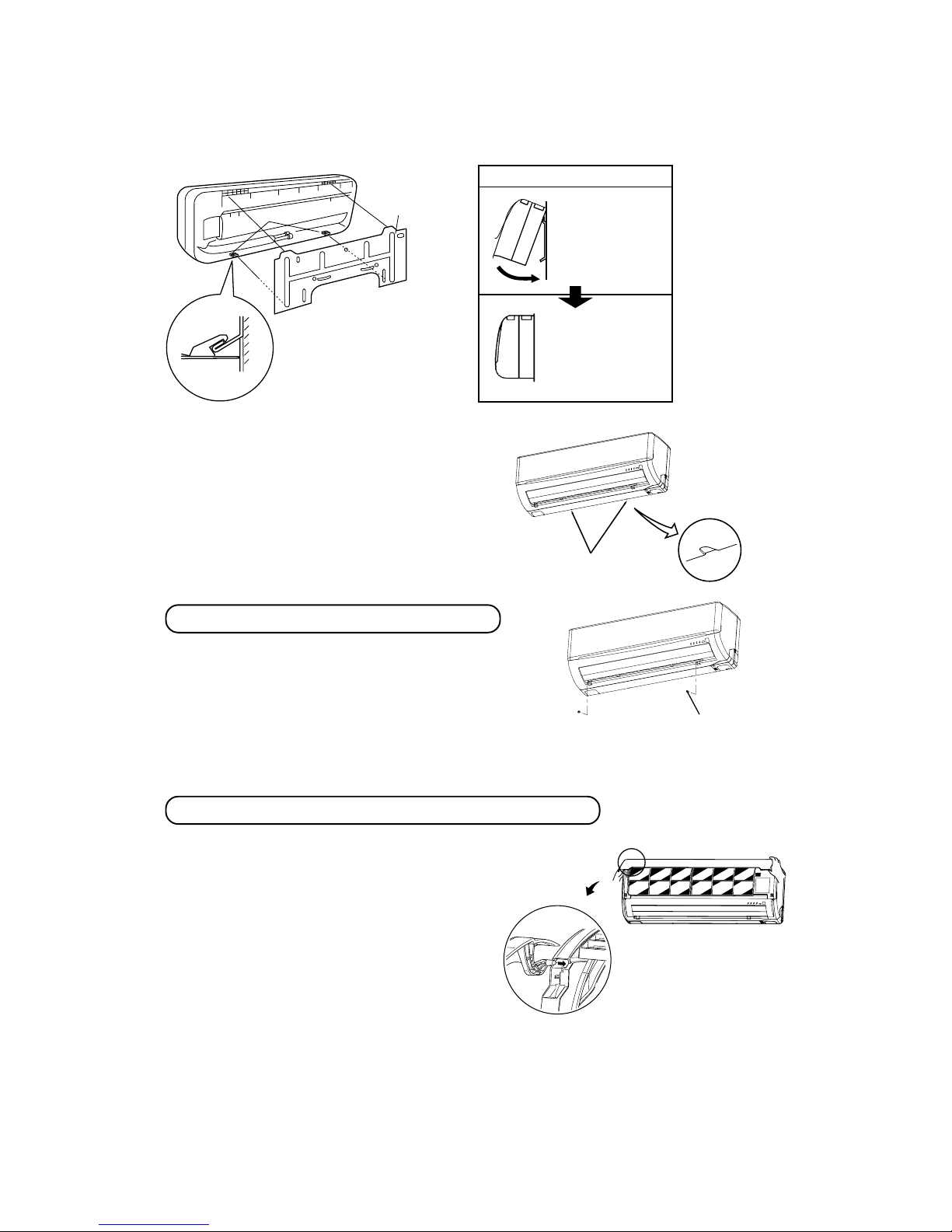
Installing steps
1.Hook the upper part
of the indoor unit to
the installation board.
2.The unit can be installed
simply by gently pushing in the lower part.
5 Securing the indoor unit to the installation board
Wall
Indoor u nit
base low er latch
Installa tion
board
Latch ( 2 locati ons)
Installa tion
board
Indoor u nit
•
How to remove the indoor unit from the installation board
1 Push up at the marked portion of the indoor unit
base lower latch, and slightly pull it toward you.
(both right and left hand sides)
(The indoor unit base lower latch can be removed
from the installation board)
2 Push up the indoor unit upward. So the indoor unit
will be removed from the installation board.
The marked portion of the
Indoor unit bese lower latch
Lid
Removal and installation of the front panel
Open/close and detachment/attachment of air inlet panel
Set scre ws
1 Removing
• Remove the 2 set screws.
• Move the lower part of the panel forward and push upwards to
remove. (Remove the 3 latches in the upper section.)
2 Fitting
• Do remove the air filter.
• Cover the body with the front panel.
• Tighten the 2 set screws.
• Fit the air filter. Carry out in the above order.
1 To open, pull the panel at both ends of lower part and release
latches, then pull up the panel until you feel resistance. (The
air inlet panel stops at approx. 60˚ open position.)
2 To close, hold the panel at both ends of lower part to lower
downward and push it slightly until the latch works, then
push the center portion slightly.
3 To remove, pull up the panel to the position shown in right
illustration and pull it toward you.
4 To install, insert the air inlet panel arm into the slot on the
front panel from the position shown in right illustration, hold
the panel at both ends of lower part, lower it downward
slowly, then push it slightly until the latch works and further
push the center portion slightly.
Page 21
-
19
-
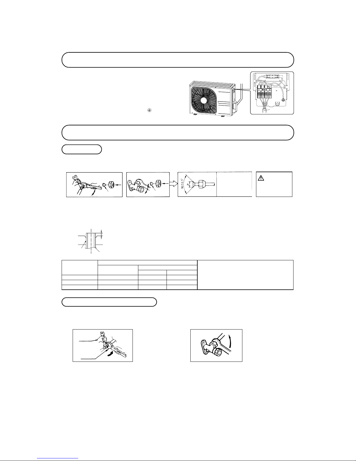
Installation of outdoor unit
1 Make sure that the unit is stable in installation. Fix the
unit to stable base.
2 Perfrom wiring, making wire terminal numbers conform
to terminal numbers of indoor unit terminal block.
3 Earth lead wire shall be longer than the other lead wires
for the electrical safety in case of the slipping out of the
cord from the anchorage.
Connect using ground screw located near mark.
Connection of refrigerant pipings
Preparation
Connection of refrigerant piping
Keep the openings of the pipes covered with tapes etc. to prevent dust, sand, etc. from entering them.
• Specified torquing value:
Liquid side (ø6.35) : 14~18N·m (1.4~1.8kgf·m)
Gas side (ø9.52) : 34~42N·m (3.4~4.2kgf·m)
Gas side (ø12.7) : 49~62N·m (4.9~6.2kgf·m)
• Use one more spanner to fix the valve.
¡ Remov e the flar ed nuts.
(on both liquid an d gas sid es)
¡ Remov e the flared nuts.
(on bo th liquid and gas
sides)
¡ Instal l the removed fl ared nuts to the pipes to
be conne cted, then flare th e pipes.
Dimensio n A
Liquid si de
(ø6.35): 9.0 dia
Gas side
(ø9.52): 13.0 dia
(ø12.7): 16.2 dia
Press
Remove
Remove
(Do not
turn)
Spanner
for fixi ng
the pipin g)
Torque
wrench
• Specified torquing value:
Liquid side (ø6.35) : 14~18N·m (1.4~1.8kgf·m)
Gas side (ø9.52) : 34~42N·m (3.4~4.2kgf·m)
Gas side (ø12.7) : 49~62N·m (4.9~6.2kgf·m)
1 Indoor unit side
2 Outdoor unit side
1 Indoor unit side 2 Outdoor unit side
• Connect firmly gas and liquid side
pipings by Torque wrench.
• Connect firmly gas and liquid side
pipings by Torque wrench.
• Always use a Torque wrench and back up spanner to tighten the flare nut.
Use a flare tool designed for R410A or a conventional flare tool.
Please note that measurement B (protrusion from the flaring
block) will vary depending on the type of a flare tool in use.
If a conventional flare tool is used, please use a copper pipe
gauge or a similar instrument to check protrusion so that you can
keep measurement B to a correct value.
Copper pipe diameter
Clutch type flare tool f or
R410A
Conventional (R22) flare tool
Clutch type Wing nut type
Measurement B (mm)
ø6.35
ø9.52
ø12.7
0.0 ~ 0.5
0.0 ~ 0.5
0.0 ~ 0.5
1.0 ~ 1.5
1.0 ~ 1.5
1.0 ~
1.5
1.5 ~ 2.0
1.5 ~ 2.0
2.0 ~ 2.5
Do not apply refrigerating
machine oil to the flared
surface.
CAUTION
Measurement B
Flaring block
Copper pipe
¡Flaring work
Indoor - Outdoor
connecting wire
Page 22

-
20
-
Insulation of connecting portion
1 Cover the connection portion of the refrigerant piping with the
pipe cover and seal them.
If neglecting to do so, moisture occurs on the piping and water
will drip out.
2 Finishing and fixing
a Tie up the piping with wrapping tape, and shape it so that it conforms
to which the pipe is attached.
b Fix them with clamps as right figure.
Vinyl tap e
To cov er the connecting portion with insulation materi als, cut upper port ion and then seal
it with i nsulation materials .
Cover the exte rior portion wit h covering tape and shape the pi ping so it
will matc h the cont ours of th e route
that t he pip ing to take. Also fix the
wiring and pipings to the w all wit h
clamps.
Insulati on
Refriger ant piping
Electric al wiring
Covering tape
Drain hos e
Tapping s crew
♦ Additional refrigerant charge
Air purge
1 Tighten all flare nuts in the pipings both
indoor and outside wa ll so as not to
cause leak.
2 Connect serv ice valve, char ge hose,
manifold valve and vacuum pump as is
illustrated below.
3 Open manifold valve handle Lo to its
fu ll wid th, and per fo rm vacu um or
evacuation.
Continue the vacuum or evacuation operation for 15 min utes or more and
che ck to see tha t the vacuum gau ge
reads – 0.1 MPa (– 76 cmHg).
4 After comp leting vac uum operat ion,
fully open service valve (Both gas and
li qu id sid es ) w it h hexa go n head ed
wrench.
5 Detach the charge hoses.
6 Check for possible leakage of gas in the
connection parts of both indoor and outdoor.
(three-way valve)
Charge hose (Designed specifically for R410A)
Compound pressure gauge
Pressure gauge
Gauge manifold
(Designed specifically for R410A)
Handle Hi
Vacuum pump
Vacuum pump adapter
(Anti-reverse flow type)
(Designed specifically for R410A)
Charge hose
(Designed specifically for R410A)
Check joint
-0.1MPa
(-76cmHg)
Handle Lo
Operation valve
Operation valve
(two-way valve)
Operation valve
cap
Operation valve
cap
Operation valve cap
tightening torque (N•m)
Check joint blind nut
tightening torque (N•m)
ø6.35 (1/4")
ø9.52 (3/8") 10~12
ø12.7 (1/2") 25~35
20~30
Operation valve size
(mm)
Securely tighten the operation valve cap and the check joint blind nut after adjustment.
¡Since the system uses check joints differing in diameter from those found on the conventional models, a charge hose (for R22) presently in use is
not applicable.
Please use one designed specifically for R410A.
¡Please use an anti-reverse flow type vacuum pump adapter so as to prevent vacuum pump oil from running back into the system.
Oil running back into an air-conditioning system may cause the refrigerant cycle to break down.
Model SRK/C10YJV-S SRK/C13YJV-S
Additional refrigerant
Less than 10m : Not required
More than 10m : 20g/m
Not required
How to relocate or dispose of the unit
• In order to protect the environment, be sure to pump down (recovery of
refrigerant).
• Pump down is the method of recovering refrigerant from the indoor unit
to the outdoor unit when the pipes are removed from the unit.
<How to pump down>
1 Connect charge hose to check joint.
2 Liquid side : Close the liquid valve with hexagon wrench key.
Gas side : Fully open the gas valve.
Carry out cooling operation. (If indoor temperatur e is low, operate
forced cooling operation.)
3 After low pressure gauge become 0.01MPa, stop cooling operation and
close the gas valve.
¡Forced cooling operation
Turn on a power supply again after a while after turn
off a power supply. Then press continually the ON/
OFF button 5 seconds or more.
Unit ON/OFF button
Page 23

-
21
-
Installation of remote control switch
Mounting method of battery
Earthing work
-
-
+
+
• Uncover the remote control switch, and mount the batteries [R03(AAA, Micro)× 2 pieces] in the body regularly.
(Fit the poles with the indication marks, , & . without
fail)
• Earth work shall be carried out without fail in order to prevent electric shock and noise generation.
• The connection of the earth cable to the following substances causes dangerous failures, therefore it shall never be done.
City water pipe, Town gas pipe, TV antenna, lightning conductor, telephone line, etc.
Trial run and operation
1 Conduct trial run after confirming that there is no gas leaks.
2 When conducting trial run set the remote control thermostat to continuous operation position. However when the power source
is cut off or when the unit’s operation switch is turned off or was turned to fan operation position, the unit will not go into
operation in order to protect the compressor.
3 Explain to the customer on the correct usage of the air-conditioner in simple layman’s terms.
4 Make sure that drain flows properly.
Battery
Cover
Fixing to pillar or wall
• Conventionally, operate the wireless remote control
by holding in your hand.
• Avoid installing it on a clay wall etc.
Screws
CAUTION
Do not use new and
old batteries together.
Installations test check points
Check the following points again after completion of the installation, and before turning on the power. Conduct a test run again and
ensure that the unit operates properly.
At the same time, explain to the customer how to use the unit and how to take care of the unit following the instruction manual.
After installation
The power supply voltage is correct as the rating.
No gas leaks from the joints of the operation valve.
Power cables and crossover wires are securely fixed
to the terminal board.
Operation valve is fully open.
The pipe joints for indoor and outdoor pipes have
been insulated.
Test run
Air conditioning operation is normal.
No abnormal noise.
Water drains smoothly.
Protective functions are not working.
The remote control is normal.
Operation of the unit has been explained to the customer.
(Three-minute restart preventive timer)
When the air conditioner is restarted or when changing the operation, the unit will not start operating for approximately 3 minutes.
This is to protect the unit and it is not a malfunction.
Page 24

-
22
-
Remote controller
7.
OUTLINE OF OPERATION CONTROL BY MICROCOMPUTER
(1) Operation control function by remote controller
S
Operation section
Operation and indication section for remote control
Operation section
SRK10YJV-S
SRK13YJV-S
FAN SPEED button
Each time the button is pushed, the
indicator is switche d over in t urn.
•
The above illustrati on shows al l controls, but in pra ctice
only the r elevant pa rts are sho wn.
OPERATION MODE select button
Each time the button pushed, th e
indicator is switche d over in t urn.
ON/OFF (luminous) button
Press for starting o peration, p ress again
for stoppi ng.
HI POWER/ECONO button
This butt on ch anges th e HIG H POWER/
ECONOMY mo de.
Page 14
AIR FLOW (UP/DOWN) button
This butto n changes the air flo w (up/down) mode.
This butto n changes the air flo w (left/rig ht) mode.
Page 10
SLEEP button
This butto n changes to SLEEP op eration.
Page 11
CLEAN switch
This switc h changes the CLEAN m ode.
Page 15
ON TIMER button
This butto n selects ON TIMER op eration.
Page 12
AIR FLOW (LEFT/RIGHT) button
Page 10
3D AUTO button
Thi s b utto n set s 3 D AU TO op erat ion.
Thi s b utto n can cel s th e ON time r, OF F
timer, and SLEEP ope ration.
CANCEL button
RESET switch
Switch for resetting microcompu ter and
setting ti me.
Page 13, 17
OFF TIMER button
This butto n selects OFF TIMER o peration.
Page 11
TEMPERATURE button
This butto n sets the room tempe rature.
(This butt on changes the presen t time and
TIMER time .)
Page 10
Unit indication section
SRK10YJV-S
SRK13YJV-S
3D AUTO light (green)
Illuminate s during 3 D AUTO oper ation.
HI POWER light (green)
Illuminate s during H IGH POWER o peration.
RUN light (green)
Illuminate s during o peration
and CLEAN operation .
TIMER light (yellow)
Illuminate s during T IMER operat ion.
Unit display section
Page 25

-
23
-
(2) Unit ON/OFF button
When the remote controller batteries become weak, or if the remote controller is lost or malfunctioning, this button may be used to
turn the unit on and off.
(a) Operation
Push the button once to place the unit in the automatic mode. Push it once more to turn the unit off.
(b) Details of operation
The unit will go into the automatic mode in which it automatically determines, from room temperature (as detected by sensor),
whether to go into the cooling or thermal dry modes.
(3) Auto restart function
(a) Auto restart function records the operational status of the air-conditioner immediately prior to be switched off by a power cut,
and then automatically resumes operations after the power has been restored.
(b) The following settings will be cancelled:
1)
Timer settings
2)
HIGH POWER operations
Notes (1) Auto restart function is set at on when the air-conditioner is shipped from the factory. Consult
with your dealer if this function needs to be switched off.
(2) When power failure ocurrs, the timer setting is cancelled. Once power is resumed, reset the timer.
(3)
If the jumper wire (J12) “AUTO RESTART” is cut, auto restart is disabled. (See the diagram at right)
(4) Custom cord switching procedure
If two wireless remote controller are installed in one room, in order to prevent wrong operation
due to mixed signals, please modify the printed circuit board in the indoor unit’s control box
and the remote controller using the following procedure. Be sure to modify both boards. If
only one board is modied, receiving (and operation) cannot be done.
(a) Modifying the indoor unit’s printed circuit board
Take out the printed circuit board from the control box and cut off jumper wire (J13)
using wire cutters.
After cutting of the jumper wire, take measures to prevent contact with the other the lead
wires, etc.
(b) Modifying the wireless remote controller
1) Remove the battery.
2) Cut the jumper wire shown in the gure at right.
Jumper wire (J12)
Jumper wire (J13)
Cut
Function
Operation mode
Room temperature
setting
Fan speed
Flap
Timer switch
Cooling
About 24ºC
Auto Auto Continuous
Thermal dry
About 24ºC
Unit ON/OFF button
In emergen cies, this button c an be used for turni ng on/off the unit when
remote con trol is not availab le.
Page 15
RUN light (green)
Illuminate s during operation
and CLEAN operation.
TIMER light (yellow)
Illuminate s during TIMER oper ation.
Unit ON/OFF button
Page 26

-
24
-
'09•SRK-DB-087D
(5)ޓFlap and louver control
(a) Flap
(b) Louver
(c) Swing
1)
2)
(c) Memory flap (Flap or Louver stopped)
(d) When not operating
COOL , DRY, FAN
Remote controller
display
Approx. 10° Approx. 20° Approx. 30°
(Swing)
(Flap stopped)
Approx. 45° Approx. 60°
Angle of Flap from Horizontal
Center installation
Remote controller
display
Right end installation
Left end installation
Angle of Louver
Left Approx. 45°
Left Approx. 45°
Left Approx. 20°
Left Approx. 30°
Center
Left Approx. 20°
Right Approx. 20°
Center
Right Approx. 45°
Right Approx. 20°
Left Approx. 20°
Center
Right Approx. 20° Right Approx. 30° Right Approx. 45°
(Louver stopped)
(Swing) (Spot) (Wide)
In COOL, DRY, FAN operation
Approx.
10°
Approx. 60°
'09•SRK-DB-087D
(6)ޓ3D auto operation
(a)
1)
2)
(b)
At cooling
Air flow selection
Operation mode
AUTO HI MED LO
Indoor temp. – Setting temp. >5°C
Indoor temp. – Setting temp. 5°C
HIGH POWER AUTO
HI MED LO
<
=
Flap
Louver
Cooling
Up/down Swing
Wide (Fixed)
Flap
Louver
Cooling
Left/right Swing
Horizontal blowing (Fixed)
Flap
Louver
Cooling
Up/down Swing
Center (Fixed)
Wide (Fixed)
Flap
Louver
Cooling
Horizontal blowing (Fixed)
Operation mode
Indoor temp. – Setting temp. 2°C
At cooling
Air flow direction contorol
2°C <
Indoor
temp.
–
Setting temp. 5°C
Indoor temp. – Setting temp. > 5°C
The control in d) continues. Control returns to the control in b). Control returns to the control in a).
<
=
<
=
Wide (Fixed)
Flap
Air flow selection
Louver
According to DRY operation.
Horizontal blowing (Fixed)
a)
b)
c)
d)
e)
c
d
Page 27

-
25
-
'09•SRK-DB-087D
(6)ޓ3D auto operation
(a)
1)
2)
(b)
At cooling
Air flow selection
Operation mode
AUTO HI MED LO
Indoor temp. – Setting temp. >5°C
Indoor temp. – Setting temp. 5°C
HIGH POWER AUTO
HI MED LO
<
=
Flap
Louver
Cooling
Up/down Swing
Wide (Fixed)
Flap
Louver
Cooling
Left/right Swing
Horizontal blowing (Fixed)
Flap
Louver
Cooling
Up/down Swing
Center (Fixed)
Wide (Fixed)
Flap
Louver
Cooling
Horizontal blowing (Fixed)
Operation mode
Indoor temp. – Setting temp. 2°C
At cooling
Air flow direction contorol
2°C <
Indoor
temp.
–
Setting temp. 5°C
Indoor temp. – Setting temp. > 5°C
The control in d) continues. Control returns to the control in b). Control returns to the control in a).
<
=
<
=
Wide (Fixed)
Flap
Air flow selection
Louver
According to DRY operation.
Horizontal blowing (Fixed)
a)
b)
c)
d)
e)
c
d
Page 28

-
26
-
'09•SRK-DB-087D
(b) Sleep timer operation
(7)ޓTimer operation
(a) Comfortable timer setting (ON timer)
(c) OFF timer operation
(8)ޓInstallation location setting
(a) Setting
1)
If the air conditioning unit is running, press the ON/OFF button to stop.
2) Press the AIR FLOW (UP/DOWN) button and the
AIR FLOW (LEFT/RIGHT) button together for 5 seconds
or more.
3) Setting the air-conditioning installation location.
4) Press the ON/OFF button.
Airf low range Airf low rangeAirf low range
(Left End Installation) (Center Installation) (Right End Installation)
(Center Installation) (Right End Installation) (Left End Installation)
,
Installation location setting
3
Setting the air-conditioning installation location.
Each time the AIR FLOW (LEFT/RIGHT) button is pressed, the
indicator is switched in the order of:
Press the AIR FLOW (LEFT/RIGHT) button and adjust to the
desired location.
Take the air conditioning unit’s location into account and adjust the left/right airflow range to maximize air-conditioning.
(Center Installation) (Right End Installation) (Left End Installation)
2
Press the AIR FLOW (UP/DOWN) button and the
AIRFLOW (LEFT/RIGHT) button together for 5 seconds
or more.
The installation location display illuminates.
1
If the air conditioning unit is running, press the ON/OFF
button to stop.
The installation location setting cannot be made while the unit is running.
Page 29

-
27
-
27.5
25.5
19.5
18
30
(9) Outline of cooling operation
(a) Operation of major functional components in Cooling mode
(b) Detail of control in each mode (Pattern)
1) Fuzzy operation
During the fuzzy operation, the air ow and the compressor command speed are controlled by calculating the difference
between the room temperature setting correction temperature and the suction air temperature.
ON OFF OFF
ON
OFF
(few minutes ON)
OFF
(few minutes ON)
ON ON ON
Thermostat ON Thermostat OFF Failure
Cooling
Compressor
Indoor fan motor
Outdoor fan motor
20~74rps
20~74rps
20~98rps
20~98rps
20~52rps 20~74rps
20~38rps 20~46rps
Model
Fan speed
SRK10YJV-S SRK13YJV-S
Auto
MED
HI
LO
(10) Outline of automatic operation
(a) Determination of operation mode
The unit checks the indoor air temperature and the outdoor air temperature, determines the operation mode, and then begins in
the automatic operation.
Dehumidifying
Cooling
Indoor air temperature (˚C)
Outdoor air temperature (˚C)
(b)
The unit checks the temperature every hour after the start of operation and, if the result of check is not same as the previous op
-
eration mode, changes the operation mode.
(c)
When the unit is started again within one hour after the stop of automatic operation or when the automatic operation is selected
during cooling or dehumidifying operation, the unit is operated in the previous operation mode.
(d)
Setting temperature can be adjusted within the following range. There is the relationship as shown below between the signals of
the wireless remote controller and the setting temperature.
Signals of wireless remote controller (Display)
–6 –5 –4 –3 –2 –1
±
0 +1 +2 +3 +4 +5 +6
Setting
Cooling
18 19 20 21 22 23 24 25 26 27 28 29 30
temperature
Dehumidifying
19 20 21 22 23 24 25 26 27 28 29 30 31
Page 30

-
28
-
(11) Protective control function
(a) Frost prevention for indoor heat exchanger
(During cooling or dehumidifying)
1) Operating conditions
a) Indoor heat exchanger temperature (Th2) is lower than 5ºC.
b) 8 minutes after reaching the compressor command speed except 0 rps.
2) Detail of anti-frost operation
5°C or lower 2.5°C or lower
Item
model 10 : 44 rps
Upper limit speed
model 13 : 70 rps
0rps
Indoor fan
Depends on operation mode
Protects the fan tap just before
frost prevention control
Outdoor fan
Depends on operation mode Depends on stop mode
3) Reset conditions:
The indoor heat exchanger temperature (Th2) is 8ºC or higher after 5 minutes of operation following
control of the compressor command speed upper is 0 rps.
Indoor heat exchanger
temperature
Indoor heat exchanger
temperature (ºC)
2.5 5 8
0 rps
Upper
limit
speed
Compressor
command
speed
(b) Cooling overload protective control
1) Operating conditions:
When the outdoor unit is operating with the compressor command speed of other than 0 rps, and when
the outdoor air temperature sensor (TH2) becomes 41ºC or over for 30 seconds continuously.
2) Detail of operation
a) Outdoor fan is stepped up by 3 speed step. (Upper limit speed is 7th speed.)
b) The lower limit of compressor command speed is set to 30 rps and even if the calculated result becomes lower than that
after fuzzy calculation, the speed is kept to 30 rps. However, when the thermo becomes OFF, the speed is reduced to 0 rps.
3)
Reset conditions:
When either of the following condition is satised.
a) When the outdoor air temperature becomes 40ºC or less.
b) When the compressor command speed is 0rps.
(c) Compressor overheat protection
1) Purpose:
It is designed to prevent deterioration of oil, burnout of motor coil and other trouble resulting from the com
-
pressor overheat.
2) Detail of operation
a)
Speeds are controlled with temperature detected by the sensor mounted on the discharge pipe.
(Example) Fuzzy
Notes (1) When the discharge pipe temperature is in the range of 100 to 110ºC, the speed is reduced by 4 rps.
(2) When the discharge pipe temperature is raised and continues operation for 20 seconds without changing, then the speed is reduced again by 4 rps.
(3) If the discharge pipe temperature is still 90ºC or greater but less than 100ºC even when the compressor command speed is maintained for 3 minutes
when the temperature is 90ºC or greater but less than 100ºC, the speed is raised by 2 rps and kept at that speed for 3 minutes. This process is
repeated until the compressor command speed is reached.
(4) Lower limit speed
Cooling
Models 10, 13
20 rps
b)
If the temperature of 110ºC is detected by the sensor on the discharge pipe, then the compressor will stop immediately.
When the discharge pipe temperature drops and the time delay of 3 minutes is over, the unit starts again within 1 hour
but there is no start at the third time.
Discharge pipe temperature (˚C)
Lower limit
(4)
After lapse of 3 min. or over
(3)
After lapse of 3 min. or over
(3)
After lapse of 3 min. or over
(3)
4 rps
4 rps
(1)
0 rps
90 100 110
Page 31

-
29
-
(d) Current safe
1) Purpose:
Current is controlled not to exceed the upper limit of the setting operation current.
2) Detail of operation:
Input current to the converter is monitored with the current sensor xed on the printed circuit board
of the outdoor unit and, if the operation current value reaches the limiting current value, the compressor
command speed is reduced.
If the mechanism is actuated when the speed of compressor command is less than 30 rps, the
compressor is stopped immediately. Operation starts again after a delay time of 3 minutes.
(e) Current cut
1) Purpose:
Inverter is protected from overcurrent.
2) Detail of operation:
Output current from the converter is monitored with a shunt resistor and, if the current exceeds the
setting value, the compressor is stopped immediately. Operation starts again after a delay time of
3 minutes.
(f) Outdoor unit failure
This is a function for determining when there is trouble with the outdoor unit during air conditioning.
The compressor is stopped if any one of the following in item 1), 2) is satised. Once the unit is stopped by this function, it is not
restarted.
1) When the input current is measured at 1 A or less for 3 continuous minutes or more.
2) If the compressor command sends a 0 rps signal to the indoor unit 3 times or more within 20 minutes of the power being
turned on.
(g) Inching prevention
When the compressor goes into the thermo operation within 10 minutes since operation start or becomes various dehumidifying
operations, the operation is continued with the lower limit speed forcibly.
(h) Indoor fan motor protection
When the air conditioner is operating and the indoor fan motor is turned ON, if the indoor fan motor has operated at 300 rpm or
under for more than 30 seconds, the unit enters rst in the stop mode and then stops the entire system.
(i) Serial signal transmission error protection
1) Purpose:
Prevents malfunction resulting from error on the indoor ↔ outdoor signals.
2) Detail of operation
a)
When the outdoor unit controller cannot receive signals from the indoor unit
If the compressor is operating and a serial signal cannot be received from the indoor control with outdoor control hav-
ing serial signals continuously for 1 minute and 55 seconds, the compressor is stopped.
After the compressor has been stopped, it will be restarted after the compressor start delay if a serial signal can be re-
ceived again from the indoor control.
b) When the indoor unit controller cannot receive signals from the outdoor unit
i) If the outdoor unit inverter signals cannot be received for 10 seconds continuously during the transfer error check
at the rst time after turning on the power supply, the compressor is stopped immediately.
ii) If the outdoor unit inverter signals cannot be received for 1 minute and 50 seconds continuously, it tries to restart
two time but stops the operation at third failure of restart.
(j) Rotor lock
If the motor for the compressor does not turn after it has been started, it is determined that a compressor lock has occurred and
the compressor is stopped.
(k) Outdoor fan motor protection
If the outdoor fan motor has operated at 75rpm or under for more than 30 seconds, the compressor and fan motor are stopped.
Page 32

-
30
-
8. MAINTENANCE DATA
(1) Cautions
(a) If you are disassembling and checking an air conditioner, be sure to turn off the power before beginning. When working on
indoor units, let the unit sit for about 1 minute after turning off the power before you begin work. When working on an outdoor
unit, there may be an electrical charge applied to the main circuit (electrolytic condenser), so begin work only after discharg-
ing this electrical charge (to DC 10 V or lower).
(b) When taking out printed circuit boards, be sure to do so without exerting force on the circuit boards or package components.
(c) When disconnecting and connecting connectors, take hold of the connector housing and do not pull on the lead wires.
(2) Items to check before troubleshooting
(a) Have you thoroughly investigated the details of the trouble which the customer is complaining about?
(b) Is the air conditioner running? Is it displaying any self-diagnosis information?
(c) Is a power supply with the correct voltage connected?
(d) Are the control lines connecting the indoor and outdoor units wired correctly and connected securely?
(e) Is the outdoor unit’s service valve open?
(3) Troubleshooting procedure (If the air conditioner does not run at all)
If the air conditioner does not run at all, diagnose the trouble using the following troubleshooting procedure. If the air condi-
tioner is running but breaks down, proceed to troubleshooting step (4).
Important
When all the following conditions are met, we say that the air conditioner will not run at all.
(a) The RUN light does not light up.
(b) Theapsdonotopen.
(c) The indoor unit fan motors do not run.
(d) The self-diagnosis display does not function.
YES
YES
YES
NO
NO
NO
NO
YES
Troubleshooting procedure (If the air conditioner does not run at all)
Is the cor rec t v olt age
connected for the power
supply?
With the power off, do
theapsopenmanually,
then close again when
the power is turned on?
Is the r e a re c e pt i o n
sound emitted from the
unit when it is operated
by the remote controller?
Replace the indoor PCB and
perform an operation check.
Make sure the correct voltage is connected, then perform an operation check.
Is the current fuse on the indoor unit PCB blown?
Proceed to the indoor PCB
check.
Proceed to the wireless remote
controll er trou bl eshooting
procedure.
If the package components
are not damaged, replace
the fuse and perform an operation check again.
* If the voltage is correct, it will be
within the following voltage range.
198 ~ 242 V
Page 33

-
31
-
(4) Troubleshooting procedure (If the air conditioner runs)
NO
NO
NO
NO
YES
YES
YES
YES
Note (1) Even in cases where only intermittent stop data are generated, the air conditioning system is normal. However, if the same protective operation recurs
repeatedly (3 or more times), it will lead to customer complaints. Judge the conditions in comparison with the contents of the complaints.
Conrmthecontentsofthecustomercomplaint.
Check the self-diagnosis display.
Eliminate the cause of the trouble and perform an
operation check.
The air conditioning system is operating normally.
Replace the faulty component, then perform an
operation check.
Identify the faulty component by using the check
procedure corresponding to the content of the trouble.
Using the Service mode, access the self-diagnosis
displays generated in the past.
Using the Service mode, access the stop history due
to protection control generated in the past.
Is there a history of stops due
to protection control?
(1)
Is there a history of selfdiagnosis display items?
Is an error code displayed by
the self-diagnosis function?
The cause of the trouble can
bespecicallyidentied.
See page 32.
See pages 33~36.
See pages 33~36.
Page 34

-
32
-
(5) Self-diagnosis table
Whenthisairconditionerperformsanemergencystop,thereasonwhytheemergencystopoccurredisdisplayedbytheashingof
display lights. If the air conditioner is operated using the remote controller 3 minutes or more after the emergency stop, the trouble
display stops and the air conditioner resumes operation.
(1)
Notes (1) The air conditioner cannot be restarted using the remote controller for 3 minutes after operation stops.
When a heat exchanger sensor wire disconnection is detected while operation is
stopped. (If a temperature of –20ºC or lower is detected for 15 seconds, it is
judged that the wire is disconnected.)
(Not displayed during operation.)
When a room temperature sensor wire disconnection is detected while operation
is stopped. (If a temperature of –20ºC or lower is detected for 15 seconds, it is
judged that the wire is disconnected.)
(Not displayed during operation.)
• Broken heat exchanger sensor
wire, poor connector
connection
• Indoor PCB is faulty
• Broken room temperature
sensor wire, poor connector
connection
• Indoor PCB is faulty
When conditions for turning the indoor unit’s fan motor on exist during air
conditioner operation, an indoor unit fan motor speed of 300 rpm or lower is
measured for 30 seconds or longer. (The air conditioner stops.)
• Defective fan motor, poor
connector connection
ON
1 time
flash
ON
2 time
flash
ON
6 time
flash
When an outdoor temperature sensor wire disconnection is detected while
operation is stopped. (If a temperature of –40ºC or lower is detected for 15
seconds, it is judged that the wire is disconnected.)
(The compressor is stopped.)
• Broken outdoor air temp.
sensor wire, poor connector
connection
• Outdoor PCB is faulty
1 time
flash
Keeps
flashing
When a sensor wire disconnection is detected while operation is stopped.
(If a temperature of –50ºC or lower is detected for 15 seconds, it is judged that
the wire is disconnected.)
(The compressor is stopped.)
• Broken heat exchanger sensor
wire, poor connector
connection
• Outdoor PCB is faulty
2 time
flash
Keeps
flashing
When a compressor discharge pipe sensor wire disconnection is detected for
15 seconds or longer (less than 7ºC) after the compressor command speed has
continued at 0 rps or higher for 9 minutes.
(The compressor is stopped.)
• Broken discharge pipe sensor
wire, poor connector
connection
• Outdoor PCB is faulty
4 time
flash
Keeps
flashing
The inverter output current (compressor motor current) exceeds the set value
during compressor start.
(The air conditioner stops.)
• Compressor locking, open
phase on compressor output,
shortcircuit on power
transistor, closed service valve
1 time
flash
ON
When there is an emergency stop caused by trouble in the outdoor unit, or the
input current value is found to be lower than the set value.
(The air conditioner stops.)
When there is an emergency stop caused by trouble in the outdoor unit, or the
input current value is found to be lower than the set value continuously for 3
minutes or longer.
(The compressor is stopped.)
• Broken compressor wire
• Compressor blockage
2 time
flash
ON
When the value of the discharge pipe sensor exceeds the set value.
(The air conditioner stops.)
• Gas shortage, defective
discharge pipe sensor, closed
service valve
ON
5 time
flash
6 time
flash
ON
When there is no signal between the indoor PCB and outdoor PCB for 10
seconds or longer (when the power is turned on), or when there is no signal for
1 minute 55 seconds or longer (during operation)(the compressor is stopped).
• Defective power supply,
Broken signal wire, defective
indoor/outdoor PCB
If the compressor motor’s magnetic pole positions cannot be correctly detected
when the compressor starts.
(The air conditioner stops.)
• Defective compressor
• Open phase on compressor
• Defective outdoor PCB
2 time
flash
2 time
flash
ON
5 time
flash
When the outdoor unit’s fan motor sped continues for 30 seconds or longer at
75 rpm or lower. (3 times) (The air conditioner stops.)
• Defective fan motor, poor
connector connection
7 time
flash
ON
Indoor unit display panel
Cause Display (flashing) condition
RUN
light
TIMER
light
When the compressor command speed is lower than the set value and the current
safe has operated. (The compressor is stopped.)
• Overload operation
• Overcharge
• Compressor locking
3 time
flash
When the wrong voltage connected for the power supply.
When the outdoor PCB is faulty.
• Defective active filter
ON
• Broken power transistor
Heat exchanger
sensor error
Room
temperature
sensor error
Indoor fan
motor error
Outdoor air
temperature
sensor error
Outdoor heat
exchanger
sensor error
Discharge pipe
sensor error
Current Cut
Trouble of
outdoor unit
Over heat of
compressor
Error of signal
transmission
Rotor lock
Outdoor fan
motor error
Description
of trouble
Current safe
stop
Active f ilter
voltage error
Power transistor
error
4 time
flash
ON
Page 35

-
33
-
(6) Service mode (Trouble mode access function)
This air conditioner is capable of recording error displays and protective stops (service data) which have occurred in the past. If
self-diagnosisdisplayscannotbeconrmed,itispossibletogetagraspoftheconditionsatthetimetroubleoccurredbychecking
these service data.
(a) Explanation of terms
Explanation
Term
Service mode
Service data
The service mode is the mode where service data are displayed by flashing of the display lights
when the operations in item (b) below are performed with the indoor controller.
These are the contents of error displays and protective stops which occurred in the past in the air
conditioner system. Error display contents and protective stop data from past anomalous
operations of the air conditioner system are saved in the indoor unit controller’s non-volatile
memory (memory which is not erased when the power goes off). There are two types of data,
self-diagnosis data and stop data, described below.
Self-diagnosis data
Stop data
These are the data which display the reason why a stop occurred when an error display (selfdiagnosis display) occurred in an indoor unit. Data are recorded for up to 5 previous occurrences.
Data which are older than the 5th previous occurrence are erased.
In addition, data on the temperature of each sensor (room temperature, indoor heat exchanger,
outdoor heat exchanger, outdoor air temperature, discharge pipe), remote controller information
(operation switching, fan speed switching) are recorded when trouble occurs, so more detailed
information can be checked.
These are the data which display the reason by a stop occurred when the air conditioning system
performed protective stops, etc. in the past. Even if stop data alone are generated, the system
restarts automatically. (After executing the stop mode while the display is normal, the system
restarts automatically.) Data for up to 10 previous occasions are stored. Data older than the 10th
previous occasion are erased.
( Important) In cases where transient stop data only are generated, the air conditioner system
may still be normal. However, if the same protective stop occurs frequently (3 or
more times), it could lead to customer complaints.
(b) Service mode display procedure
NO
NO
(*1)
YES
YES
Start
Did a buzzer located in
the indoor unit sound?
Are other data displayed?
Within 1 minute after turning the air conditioner’s power on, signals will be sent from the
remote controller
(*2)
Count the number of times the RUN light and
TIMERlightash
(*3)
, and check the contents of the
error, etc. from the table. (See pages 35 and 36.)
Change the remote controller settings based on
the instructions in the table
(*4)
. (See page 34.)
*1: If the buzzer does not sound no matter how
many times you repeat the operation, the
unit ON/OFF button may be faulty.
*2: Set the remote control’s settings on “Cooling
operation,” “Fan speed: MED” and “Set temperature: 21ºC.”
Turn off the air conditioner’s power to terminate the
service mode. If you are going to turn the power on
again, wait 1 minute or longer after turning it off.
Turn the air conditioner’s power on again while
pressing the unit ON/OFF button.
Turn off the air conditioner’s power once, then
wait 1 minute or longer.
Page 36

-
34
-
*3:Tocountthenumberofashesintheservicemode,countthenumberofashesafterthelightlightsupfor1.5second
initially (start signal). (The time that the light lights up for 1.5 second (start signal) is not counted in the number of
ashes.)
*4:
When in the service mode, when the remote controller settings (operation switching, fan speed switching, temperature
setting) are set as shown in the following table and sent to the air conditioner unit, the unit switches to display of service data.
①
Self-diagnosis data
What are Self- .......These are control data (reasons for stops, temperature at each sensor, remote controller information)
diagnosis Data? from the time when there were error displays (abnormal stops) in the indoor unit in the past.
Data from up to 5 previous occasions are stored in memory. Data older than the 5th previous occasion are erased.
The temperature setting indicates how many occasions previous to the present setting the error display
data are and the operation switching and fan speed switching data show the type of data.
Remote controller setting
Contents of output data
Fan speed switching
MED
HI
AUTO
LO
MED
HI
AUTO
Displays the reason for stopping display in the past (error code).
Displays the room temperature sensor temperature at the time the error code was displayed in the past.
Displays the indoor heat exchanger sensor temperature at the time the error code was displayed in the past.
Displays the remote controller information at the time the error code was displayed in the past.
Displays the outdoor air temperature sensor temperature at the time the error code was displayed in the past.
Displays the outdoor heat exchanger sensor temperature at the time the error code was displayed in the past.
Displays the discharge pipe sensor temperature at the time the error code was displayed in the past.
Cooling
Operation switching
Fan
Remote controller setting
Indicates the number of
occasions previous to the present
the error display data are from.
Temperature setting
21ºC
22ºC
23ºC
24ºC
25ºC
1 time previous (previous time)
2 times previous
3 times previous
4 times previous
5 times previous
Remote controller setting
Fan speed
switching
Operation
switching
Displayed data
Temperature
setting
21ºC
22ºC
23ºC
24ºC
25ºC
Displays the reason for the stop (error code) the previous time an error was displayed.
Displays the reason for the stop (error code) 2 times previous when an error was displayed.
Displays the reason for the stop (error code) 3 times previous when an error was displayed.
Displays the reason for the stop (error code) 4 times previous when an error was displayed.
Displays the reason for the stop (error code) 5 times previous when an error was displayed.
Cooling MED
(Example)
0.5 sec.
1.5 sec.
RUN light
(10’s digit)
TIMER light
(1’s digit)
11-second interval
0.5 sec.
OFF
ON
OFF
ON
• In the case of current safe (heating CT1) (example: stop code “32”)
The RUN light (10’s digit) flashes 3 times and the TIMER light (1’s digit) flashes 2 times.
3 × 10 + 2 × 1 = 32 → From the table, read the instructions for error code 32, “current safe (heating CT1).
Page 37

-
35
-
②
Stop data
Remote controller setting
Fan speed
switching
Operation
switching
Displayed data
Temperature
setting
21ºC
22ºC
23ºC
24ºC
25ºC
26ºC
27ºC
28ºC
29ºC
30ºC
Displays the reason for the stop (stop code) the previous time when the air conditioner was stopped by protective stop control.
Displays the reason for the stop (stop code) 2 times previous when the air conditioner was stopped by protective stop control.
Displays the reason for the stop (stop code) 3 times previous when the air conditioner was stopped by protective stop control.
Displays the reason for the stop (stop code) 4 times previous when the air conditioner was stopped by protective stop control.
Displays the reason for the stop (stop code) 5 times previous when the air conditioner was stopped by protective stop control.
Displays the reason for the stop (stop code) 6 times previous when the air conditioner was stopped by protective stop control.
Displays the reason for the stop (stop code) 7 times previous when the air conditioner was stopped by protective stop control.
Displays the reason for the stop (stop code) 8 times previous when the air conditioner was stopped by protective stop control.
Displays the reason for the stop (stop code) 9 times previous when the air conditioner was stopped by protective stop control.
Displays the reason for the stop (stop code) 10 times previous when the air conditioner was stopped by protective stop control.
Cooling LO
(c) Error code, stop code table
(Assignment of error codes and stop codes is done in common for all models.)
(2 times)
OFF OFF
Major category
Number of flashes
when in service mode
Minor category
Error content
Stop code
or
Error code
TIMER
light
(1’s digit)
RUN
light
(10’s digit)
Cause Occurrence conditions
Error
display
Auto
recovery
1 time
flash
1 time
flash
2 time
flash
7 time
flash
3 time
flash
1 time
flash
2 time
flash
2 time
flash
3 time
flash
4 time
flash
5 time
flash
6 time
flash
7 time
flash
2 time
flash
3 time
flash
4 time
flash
5 time
flash
6 time
flash
0 Normal
Current
Cut
Outdoor
unit
error
Current
safe
11
17
31
32
33
34
35
36
37
22
12
13
14
15
16
Compressor software start
Compressor lock
Compressor wiring short circuit
Compressor output is open phase
Outdoor PCB is faulty
Compressor start fails 42 times in succession and the
reason for the final failure is current cut.
After the compressor starts, it stops due to current cut at
less than 20 rps.
When operation is stopped by current cut at 20 rps or
higher.
When the DC voltage exceeds 390V.
When it is judged that the power transistor was damaged
at the time the compressor started.
When it is judged that the power transistor was damaged
at the time the compressor started.
When the curent is 1A or less the time the compressor
started.
When there is a current safe stop in current safe I mode
during cooling operation.
When there is a current safe stop in current safe I mode
during heating operation.
When there is a current safe stop in current safe II mode
during cooling operation.
When there is a current safe stop in current safe II mode
during heating operation.
When there is a current safe stop in current safe III mode
during cooling operation.
When there is a current safe stop in current safe III mode
during heating operation.
When there is a current safe stop in current safe III + 3A
mode during heating operation.
Lower than 20 rps
20 rps or higher
Excessive voltage
Short circuit in the power
transistor (high side)
Current cut circuit
breakdown
Software current cut
Compressor wiring is
unconnection voltage drop
Cooling current safe I
Heating current safe I
Cooling current safe II
Heating current safe II
Cooling current safe III
Heating current safe III
Heating current safe
III + 3A
- - -
-
-
-
-
-
-
-
-
-
-
-
-
-
-
-
Service valve closed
Compressor output is open phase.
Electronic expansion valve is faulty.
Service valve is closed.
Compressor output is open phase.
Compressor is faulty.
Electronic expansion valve is faulty.
Overcharge
Compressor lock
Overcharge
Compressor lock
Overcharge
Compressor lock
Overcharge
Compressor lock
Overcharge
Compressor lock
Overcharge
Compressor lock
Overcharge
Compressor lock
9 time
flash
29
When the power supply voltage drops during operation.Voltage drop
-
Power supply construction is defective.
Outdoor PCB is faulty.
Compressor wiring is disconnected.
Outdoor PCB is faulty.
Service valve is closed.
Compressor output is open phase.
Compressor is faulty.
Electronic expansion valve is faulty.
Outdoor PCB is faulty.
Power transistor is damaged.
Outdoor PCB is faulty.
.
Power transistor is damaged.
Outdoor PCB is defective.
Power supply is abnormal.
3 time
flash
23
When an abnormal stop occurs 3 times with automatic
recovery within 20 minutes after the outdoor unit’s power
supply was turned on.
Abnormal stop 3 times in
20 minutes.
-
Service valve is closed.
Compressor output is open phase.
Electronic expansion valve is faulty.
Refrigerant is insufficient.
(3 times)
7 time
flash
Outdoor
fan motor
error
27
8 time
flash
28
When a fan speed of 75 rpm or lower continues for 30
seconds or longer.
Outdoor unit’s fan motor
is abnormal
Outdoor fan motor is fault
Power supply construction
is faulty.
y.
Connector connections are poor.
Outdoor PCB is faulty.
When an error voltage of 150 V or less is input
Input of abnormal
voltage
When the compressor has stopped with the current cut
after starting it
Page 38

-
36
-
Compressor software start
(within 4 seconds after
phase switching)
Current
safe
4 time
flash
1 time
flash
2 time
flash
3 time
flash
4 time
flash
5 time
flash
6 time
flash
41
1 time
flash
61
2 time
flash
62
OFF
50
6 time
flash
OFF
OFF
60
7 time
flash
70
8 time
flash
OFF
80
1 time
flash
81
2 time
flash
82
3 time
flash
83
4 time
flash
84
5 time
flash
85
6 time
flash
86
7 time
flash
87
8 time
flash
88
6 time
flash
76
42
43
44
45
46
When there is a current safe stop in overload 1 mode
during cooling operation.
When there is a current safe stop in overload 2 mode
during cooling operation.
When there is a current safe stop in overload 3 mode
during cooling operation.
When there is a current safe stop in overload 1 mode
during heating operation.
When there is a current safe stop in overload 2 mode
during heating operation.
When there is a current safe stop in overload 3 mode
during heating operation.
When the discharge pipe sensor’s value exceeds the set
value.
After the compressor starts, when the compressor stops
due to rotor lock.
When compressor start fails 42 times in succession and
the reason for the final failure is rotor lock.
When a temperature of -20ºC or lower is sensed continuously
for 40 minutes during heating operation (the compressor stops).
When a temperature of -55ºC or lower is sensed continuously
for 40 minutes during heating operation (the compressor stops).
When the indoor unit’s fan motor is detected to be
running at 300 rpm or lower speed with the fan motor in
the ON condition while the air conditioner is running.
Anti-condensation prevention control is operating.
When the anti-frost control operates and the compressor
stops during cooling operation.
When high pressure control operates during heating
operation and the compressor stops.
When compressor overheating protective control operates
and the compressor stops.
When refrigeration cycle system protective control
operates.
When 1 minute 55 seconds passes without
communications signals from either the outdoor unit or
the indoor unit being detected correctly.
When 10 seconds passes after the power is turned on without communications
signals from the indoor or outdoor unit being detected correctly.
When 1 minute 55 seconds passes without communications signals
from either the outdoor unit or the indoor unit being detected correctly.
Cooling overload 1
(outdoor temperature:
36~40ºC)
Compressor
overheat
Serial signal
transmission
error
Can’t receive signals for 1
minute 55 seconds (if
communications have recovered)
Rotor lock Rotor lock
Protective
control
operation
Indoor unit fan motor is
abnormal.
Discharge pipe sensor is
abnormal (anomalous stop).
Indoor heat exchanger sensor
is abnormal (anomalous stop).
Outdoor heat exchanger sensor is
abnormal (anomalous stop).
Anti-condensation control
Anti-frost control
High pressure control
Compressor overheating
protection control
Refrigeration cycle system
protective control
Connection lines between the
indoor and outdoor units are faulty.
Serial transmission error.
Heating overload 1
(outdoor temperature:
5~12ºC)
Cooling overload 2
(outdoor temperature:
40~45ºC)
Heating overload 2
(outdoor temperature:
12~17ºC)
Cooling overload 3
(outdoor temperature:
45ºC~)
Heating overload 3
(outdoor temperature:
17ºC~)
110ºC
-
-
-
-
-
-
-
-
-
-
-
-
-
(2 times)
(3 times)
(2 times)
(2 times)
(4 times)
-
-
-
Major category
Number of flashes
when in service mode
Minor category
Error content
Stop code
or
Error code
TIMER
light
(1’s digit)
RUN
light
(10’s digit)
Cause
Occurrence conditions
Error
display
Auto
recovery
Overcharge
Compressor lock
Overload operation
Overcharge
Compressor lock
Overload operation
Overcharge
Compressor lock
Overload operation
Overcharge
Compressor lock
Overload operation
Overcharge
Compressor lock
Overload operation
Overcharge
Compressor lock
Overload operation
Refrigerant is insufficient.
Discharge pipe sensor is faulty.
Service valve is closed.
Power supply is fault y.
Power supply cables and signal lines are improperl y wired.
Indoor or outdoor PCB is faulty.
Compressor is faulty.
Compressor output is open phase.
Electronic ex[ansion valve is faulty.
Overload operation.
Outdoor PCB is faulty
Compressor is faulty
Compressor wiring is disconnected.
Compressor wiring is short circuited.
Outdoor PCB is faulty.
Fan motor is faulty.
Connector connections are poor.
Indoor PCB is faulty.
Discharge pipe sensor wire is
disconnected.
Connector connections are poor.
Heating overload
Indoor unit fan speed drops
Indoor heat exchanger sensor short circuit
Refrigerant is insufficient.
Discharge pipe sensor is faulty.
Service valve is closed.
Service valve is closed.
Refrigerant is insufficient.
High humidity condition.
Humidity sensor is faulty.
Indoor unit fan speed drops.
Indoor heat exchanger sensor short circuit
Indoor heat exchanger sensor wire is
disconnected.
Connector connections are poor.
Outdoor heat exchanger sensor wire
is disconnected.
Connector connections are poor.
Connection lines between the indoor and
outdoor units are faulty.
Indoor or outdoor PCB are faulty.
Indoor or outdoor PCB are faulty.
Noise is causing faulty operation.
When a disconnection signal is sent for 15 seconds or longer as the
discharge pipe sensor data after the outdoor unit’s speed is 0 rps or
higher continuously for 9 minutes.
5 time
flash
Page 39

-
37
-
Note(1) ThenumberofasheswhenintheServiceModedonotincludethe1.5secondperiodwhenthe lightslightup atrst(starting signal).(Seethe example
shown below.)
0.5 sec.
1.5 sec.
RUN light
(10’s digit)
TIMER light
(1’s digit)
11-second interval
0.5 sec.
OFF
ON
OFF
ON
• In the case of current safe (heating CT1) (example: stop code “32”)
The RUN light (10’s digit) flashes 3 times and the TIMER light (1’s digit) flashes 2 times.
3 × 10 + 2 × 1 = 32 → From the table, read the instructions for error code 32, “Current safe (heating CT1).
Notes (2) Abnormal Stop:
-
Is not displayed. (automatic recovery only)
○
Displayed.
If there is a ( ) displayed, the error display shows the number of times that an automatic recovery occurred for the same reason has
reached the number of times in ( ).
If no ( ) is displayed, the error display shows that the trouble has occurred once.
Notes (3) Automatic Recovery: - Does not occur
○
Automatic recovery occurs.
(d) Remote controller information tables
1) Operation switching
RUN light
(Operation switching)
Display pattern when
in service mode
Operation switching
when there is an
abnormal stop
0
1
2
3
4
AUTO
DRY
COOL
FAN
HEAT
2) Fan speed switching
TIMER light
(Fan speed switching)
Display pattern when
in service mode
Fan speed
switching when
there is an
abnormal stop
0
2
3
4
6
7
AUTO
HI
MED
LO
HI POWER
ECONO
* If no data are recorded (error code is normal), the information display in the remote controller becomes as follows.
Remote controller setting
Operation switching
Fan speed switching
Display when error code is normal.
AUTO
AUTO
0.5 sec.
1.5 sec.
RUN light
(10’s digit)
TIMER light
(1’s digit)
11-second interval
0.5 sec.
OFF
ON
OFF
ON
(Example): Operation switching, fan speed switching, cooling HI
Page 40

-
38
-
(e) Room temperature sensor temperature, indoor heat exchanger sensor temperature, outdoor air tempera-
ture sensor temperature, outdoor heat exchanger sensor temperature table
Units: ºC
Buzzer sound
TIMER light
(1’s digit)
RUN light
(10’s digit)
Yes
(sounds for 0.1 second)
6
5
4
3
2
1
0
0
1
2
3
4
5
6
7
8
9
-60
-50
-40
-30
-20
-10
0
10
20
30
40
50
60
70
80
90
0 1 2 3 4 5 6 7 8 9
-61
-51
-41
-31
-21
-11
-1
1
11
21
31
41
51
61
71
81
91
-62
-52
-42
-32
-22
-12
-2
2
12
22
32
42
52
62
72
82
92
-63
-53
-43
-33
-23
-13
-3
3
13
23
33
43
53
63
73
83
93
-64
-54
-44
-34
-24
-14
-4
4
14
24
34
44
54
64
74
84
94
-55
-45
-35
-25
-15
-5
5
15
25
35
45
55
65
75
85
95
-56
-46
-36
-26
-16
-6
6
16
26
36
46
56
66
76
86
96
-57
-47
-37
-27
-17
-7
7
17
27
37
47
57
67
77
87
97
-58
-48
-38
-28
-18
-8
8
18
28
38
48
58
68
78
88
98
-59
-49
-39
-29
-19
-9
9
19
29
39
49
59
69
79
89
99
No
(does not sound)
* If no data are recorded (error code is normal), the display for each sensor becomes as shown below.
Sensor name
Room temperature sensor temperature
Indoor heat exchanger sensor temperature
Outdoor air temperature sensor temperature
Outdoor heat exchanger sensor temperature
Sensor value displayed when the error code is normal
-19ºC
-64ºC
-64ºC
-64ºC
(Example) Room temperature, indoor heat exchanger, outdoor air temperature, outdoor heat exchanger: “-9ºC”
0.5 sec.
0.1 sec.
1.5 sec.
Buzzer sound
If the temperature is < 0, the buzzer sounds.
If the temperature is
>
=
0, the buzzer does not sound.
11-second interval
0.5 sec.
OFF
ON
OFF
ON
OFF
ON
RUN light
(10’s digit)
TIMER light
(1’s digit)
Page 41

-
39
-
(f) Discharge pipe temperature table
Units: ºC
Buzzer sound
TIMER light
(1’s digit)
RUN light
(10’s digit)
Yes
(sounds for 0.1 second)
3
2
1
0
0
1
2
3
4
5
6
7
-60
-40
-20
0
20
40
60
80
100
120
140
0 1 2 3 4 5 6 7 8 9
-62
-42
-22
-2
2
22
42
62
82
102
122
142
-64
-44
-24
-4
4
24
44
64
84
104
124
144
-46
-26
-6
6
26
46
66
86
106
126
146
-48
-28
-8
8
28
48
68
88
108
128
148
-50
-30
-10
10
30
50
70
90
110
130
150
-52
-32
-12
12
32
52
72
92
112
132
-54
-34
-14
14
34
54
74
94
114
134
-56
-36
-16
16
36
56
76
96
116
136
-58
-38
-18
18
38
58
78
98
118
138
No
(does not sound)
* If no data is recorded (error code is normal), the display for sensor becomes as shown below.
Sensor name
Discharge pipe sensor temperature
Sensor value displayed when the error code is normal
-64ºC
(Example) Discharge pipe temperature: “122ºC”
* In the case of discharge pipe data, multiply the reading value by 2. (Below, 61 x 2 = “122ºC”)
0.5 sec.
0.1 sec.
1.5 sec.
11-second interval
0.5 sec.
OFF
ON
OFF
ON
OFF
ON
Buzzer sound
If the temperature is < 0, the buzzer sounds.
If the temperature is
>
=
0, the buzzer does not sound.
RUN light
(10’s digit)
TIMER light
(1’s digit)
Page 42

-
40
-
Service data record form
Customer
Date of investigation
Machine name
Error code on previous occasion.
Room temperature sensor temperature on previous occasion.
Indoor heat exchanger sensor temperature on previous occasion.
Remote control information on previous occasion.
Outdoor air temperature sensor temperature on previous occasion.
Outdoor heat exchanger sensor temperature on previous occasion.
Discharge pipe sensor temperature on previous occasion.
Error code on second previous occasion.
Room temperature sensor temperature on second previous occasion.
Indoor heat exchanger sensor temperature on second previous occasion.
Remote control information on second previous occasion.
Outdoor air temperature sensor temperature on second previous occasion.
Outdoor heat exchanger sensor temperature on second previous occasion.
Discharge pipe sensor temperature on second previous occasion.
Error code on third previous occasion.
Room temperature sensor temperature on third previous occasion.
Indoor heat exchanger sensor temperature on third previous occasion.
Remote control information on third previous occasion.
Outdoor air temperature sensor temperature on third previous occasion.
Outdoor heat exchanger sensor temperature on third previous occasion.
Discharge pipe sensor temperature on third previous occasion.
Error code on fourth previous occasion.
Room temperature sensor temperature on fourth previous occasion.
Indoor heat exchanger sensor temperature on fourth previous occasion.
Remote control information on fourth previous occasion.
Outdoor air temperature sensor temperature on fourth previous occasion.
Outdoor heat exchanger sensor temperature on fourth previous occasion.
Discharge pipe sensor temperature on fourth previous occasion.
Error code on fifth previous occasion.
Room temperature sensor temperature on fifth previous occasion.
Indoor heat exchanger sensor temperature on fifth previous occasion.
Remote control information on fifth previous occasion.
Outdoor air temperature sensor temperature on fifth previous occasion.
Outdoor heat exchanger sensor temperature on fifth previous occasion.
Discharge pipe sensor temperature on fifth previous occasion.
Stop code on previous occasion.
Stop code on second previous occasion.
Stop code on third previous occasion.
Stop code on fourth previous occasion.
Stop code on fifth previous occasion.
Stop code on sixth previous occasion.
Stop code on seventh previous occasion.
Stop code on eighth previous occasion.
Stop code on ninth previous occasion.
Stop code on tenth previous occasion.
MED
HI
AUTO
LO
MED
HI
AUTO
MED
HI
AUTO
LO
MED
HI
AUTO
MED
HI
AUTO
LO
MED
HI
AUTO
MED
HI
AUTO
LO
MED
HI
AUTO
MED
HI
AUTO
LO
MED
HI
AUTO
Content of complaint
Remote controller settings
Content of displayed data
Display content
Display results
Buzzer (Yes/No.)
RUN light (Times)
TIMER light (Times)
Temperature setting
21
22
23
24
25
Operation switching
Cooling
Fan
Cooling
Fan
Cooling
Fan
Cooling
Fan
Cooling
Fan
LoCooling
Judgment
Examiner
Remarks
Fan speed switching
Model
21
22
23
24
25
26
27
28
29
30
Page 43

-
41
-
(7) Inspection procedures corresponding to detail of trouble
Sensor error
[Broken sensor wire,
connector poor connection]
Is connector connection good?
YES
YES
NO
NO
Replace PCB.
Correct connection.
Replace sensor.
Is sensor resistance value good?
Indoor fan motor error
[Defective fan motor, connector poor
connection, defective indoor PCB]
Is connector connection good?
YES
NO
NO
Is the output of the indoor unit
PCB normal?
Power supply neset
NO
YES
YES
Correct connector connection
Is DC fan motor resistance value good?
Replace indoor PCB
Replace indoor fan motor
Notes (1) See pages 46 for the DC fan motor and indoor PCB check
procedure.
(2) After making sure the DC fan motor and indoor PCB are
normal, connect the co nnectors and confirm that the fan
motor is turning.
(If power is turned on while one or the other is broken down,
it could cause the other to break down also.)
* Disc onne ct the fan mo to r
connec tor, then investigate
the DC fan motor and indoor
PCB separately.
(Short circuit)
(Broken wire)
◆
S ensor tempe r atur e char a cteri s tics
(Room temp., indoor heat exchanger temp.,
outdoor heat exchanger temp., outdoor air
temp.)
Temperature (˚C)
Resistance (k
Ω
)
30
25
20
15
10
5
30
20
10
40 50 60
70
0
-
10
◆
Discharge pipe sensor temperature characteristics
0
0 20 40 60 80 100 120 135
20
40
60
80
100
120
140
160
180
(Short circuit)
(Broken wire)
Temperature (˚C)
Resistance (k
Ω
)
Is normal state restored?
Malfunction by temporary
noise
NO
Replace fan motor (If anomaly
persiste after replacing fan motor,
replace indoor PCB)
YES
Page 44

-
42
-
Current cut
[Open phase on compressor output
terminal, compressor lock]
YES
YES
NO
NO
YES
NO
¡
Check compressor wiring visually.
¡
Check insulation resistance. (1 MΩ or over)
¡
Check coil wire resistance.
Model 10, 13: 1.703
Ω
(U-V, V-W, U-W) or more at 20°C
Does current cut operate when
operating inverter with compressor
wire disconnected?
Is output voltage applied to all 3
phases of power transistor?
Is there any shortcircuit?
Inspect compressor.
Defective outdoor PCB
Defective outdoor PCB
Secure space for suction
and blow out.
If check results are normal,
compressor is locked.
Trouble of outdoor unit
[Compressor malfunction of
insufficient gas (refrigerant)]
Does compressor operation?
Is capacitor for compressor normal?
Replace compressor.
Replace heat exchanger sensor
Insufficient gas
Is refrigerant amount normal?
Is heat exchanger sensor resistance
value good?
Is connector for compressor connection
good?
Does trouble persist after charging gas?
Clogged capillary tube or strainer,
defective EEV, etc.
Replace capacitor for compressor.
Correct connection
Check if there are any places where
gas is leaking
YES
YES
NO NO
NO
NO
NO
NO
YES
YES
YES
YES
Current safe stop
[Overload operation, compressor
lock, overcharge]
Secure space for inlet and outlet.
Discharge refrigerant.
Is refrigerant charge quantity adequate?
Is outdoor ventilation condition good?
Inspect compressor.
Defective outdoor PCB
YES
YES
NO
NO
YES
Replace compressor.
NO
Page 45

-
43
-
Over heat of compressor
[Gas shortage, defective discharge
pipe sensor]
Is discharge pipe sensor
resistance value good?
(page 41)
Issufcientquantityofrefrigerant
circulated?
Defective outdoor PCB
YES
YES
NO
NO
YES
NO
Check if there are any
places where gas is leaking.
Connector connection check, resistance
value check, replacement of discharge pipe
sensor
Does trouble persist after
charging gas?
Clogged capillary tube or
strainer, defective EEV, etc.
Error of signal transmission
[Wiring error including power cable, defective indoor/
outdoor PCB]
Does error persist after power
reset?
Are the lines connecting the indoor
and outdoor units connected
normally?
Is DC 0~Approx. 12V detected
between ②~③ terminals on
indoor unit terminal block?
YES
YES
NO
NO
YES
NO
Trouble by transient cause, not unit trouble.
Correct improper wire connection on indoor/
outdoor unit.
Defective indoor PCB
YES
YES
NO
NO
Is DC 0~Appr ox. 12 V detec ted
betwee n②~③ termi nals o n
outdoo r unit termi nal bl ock?
Is AC 220V applied between
①~②
on the outdoor side terminal
block?
Defective indoor PCB. Check crossover wires.
Defective outdoor PCB
Check crossover wires.
Page 46

-
44
-
Outdoor fan motor error
[Defective fan motor, connector
poor connection, defective PCB]
Is connector connection good?
YES
NO
NO
Is the output of the outdoor PCB
normal?
Power supply reset
NO
YES
YES
Correct connector connection
Is DC fan motor resistance value good?
Replace outdoor PCB
Replace outdoor fan motor
* Discon nect the fan mo tor
connector, then investiga te
the DC fan motor and outdoor PCB separately.
Rotor lock
[Compressor defect, outdoor
PCB defect]
NO
YES
¡
Check compressor wiring visually.
¡
Check insulation resistance. (1 M
Ω
or over)
¡
Check coil wire resistance.
Model 10, 13: 1.703
Ω
(U-V, V-W, U-W) or more at 20°C
Is output voltage applied to all 3
phases of power transistor?
Inspect compressor.
Defective outdoor PCB
If check results are normal,
compressor is locked.
Is normal state restored?
Malfunction by temporary
noise
Replace fan motor (If anomaly
persiste after replacing fan motor,
replace outdoor PCB)
NO
Notes (1) See pages 48 for the DC fan motor and outdoor PCB check
procedure.
(2) After making sure the DC fan motor and outdoor PCB are
normal, connect the co nnectors and confirm that the fan
motor is turning.
(If power is turned on while one or the other is broken down,
it could cause the other to break down also.)
YES
Page 47

-
45
-
Operation
mode
Heat exchanger
sensor
Outdoor air
temperature sensor
Discharge pipe
sensor
Compressor overload protection is disabled.
(Can be operated.)
(9) Checking the indoor electrical equipment
(a) Indoor PCB check procedure
(b) Outdoor unit
Phenomenon
Sensor
Shortcircuit
Broken wire
Cooling
System can be operated normally.
Cooling
System can be operated normally.
All modes
System can be operated normally.
System can be operated normally.
Compressor stop
Is ther e voltag e betwee n termina l
blocks ① and ② ? (AC 220V)
Indoor electrical component s
are normal.
Is the voltage between termina l
blocks ② and ③ oscillating between
DC 0 and 12V?
Inspect power source
for outdoor unit.
Replace fuse.
Replace PCB.
Is the fuse burnt out? (3.15 A)
YES
YES
YES
NO
NO
NO
①
Humidity sensor operation
Failure mode Control input circuit reading
Air conditioning system operation
①
Disconnected wire Humidity reading is 0% Operates in the Dry region
②
Disconnected wire Humidity reading is 0% Operates in the Dry region
①②
Disconnected wire Humidity reading is 0% Operates in the Dry region
①
and ② are short
Humidity reading is 100% Operates in the Cooling region.
circuited
Disconnected
wire
Short
Circuit
Remark: Do not perform a continuity check of the humidity sensor with a tester. If DC current is applied, it
could damage the sensor.
Humidity sensor
element
Connector
(CnF)
Humidity sensor assembly
(8) Phenomenon observed after shortcircuit, wire breakage on sensor
(a) Indoor unit
Phenomenon
Sensor
Shortcircuit
Broken wire
Cooling
Release of continuous compressor operation command
Cooling
System can be operated normally.
Cooling
①
in the table below.
Operation
mode
Continuous compressor operation command is not released.
Continuous compressor operation command is not released.
(Anti-frosting)
①
in the table below.
Heat exchanger
sensor
Note (1) The humidity sensor is included in the model 13 only.
Room temperature
sensor
Humidity Sensor
Page 48

-
46
-
(10) How to make sure of wireless remote controller
(1)
Is remote
controller normal?
YES
Again pushing
operating switch
Operating the unit?
NO
Does unit ON/OFF
button operates?
Operating the unit.
NO
NO
YES
YES
Remote controller
defects
Abnormality is not
found.
Replace the display.
Control problem on
main unit
Is the unit
operable with remote
controller?
Defective remote
controller
NO
YES
Normal
(b) Indoor unit fan motor check procedure
This is a diagnostic procedure for determining if the indoor unit fan motor or the indoor PCB is broken down.
1) Indoor PCB output check
a) Turn off the power.
b) Remove the front panel, then disconnect the fan motor lead wire connector.
c) Turn on the power. If the unit operates when the ON/OFF button is pressed, if trouble is detected after the voltages in
thefollowinggureareoutputforapproximately30seconds,itmeansthattheindoorPCBisnormalandthefan
motor is broken down.
Ifthevoltagesin thefollowinggurearenot outputatconnectorpinsNo.
①, ④
and ⑤, the indoor indoor PCB
has failed and the fan motor is normal.
2) DC Fan motor resistance check
Notes (1) Remove the fan motor and measure it without power connected to it.
Notes (2) If the measured value is below the value when the motor is normal, it means
that the fan motor is faulty.
①②③④⑤⑥
①②③④⑤⑥
FM
I
DC15V
Indoor PCB
DC 308~336V
DC several V
(4~6 V)
CNU
(–)
GND
Blue
Yellow
White
Black
Red
Measuring Point Resistance when Normal
①
–
③
(Red – Black) 25 M
Ω
or higher
④
–
③
(White – Black) 30 k
Ω
or higher
Note (1) Check method of remote controller
(a) Press the reset switch of the remote controller.
(b) If all LCD are displayed after one (1) display, it is basically normal.
Page 49

-
47
-
Color
RD
Mark
OrangeOR
Yellow/GreenY/G
BlackBK
YellowY
WhiteWH
Red
(BK)
C-2
G1
(RD)
(Y/G)
S.IN(WH)
R.IN
(BK)
(WH)
(RD)
PWB ASSY
250V 20A
F2
F3 250V 1A
F4
250V 10A
F1
250V 2A
CIRCUIT
PAM
SWITCHING POWER
CIRCUIT
NW
NV
NU
P
W
V
U
TRANSISTOR
POWER
W
V
U
FILTER
NOISE
CNTH
CNEEV
CNFAN
M
M
3~
250V 15A
(Y/G)
T1
T2
(OR)
(Y)
M
t゜
TH1 TH2 TH3
EEV
FMo
CM
t゜ t゜
t゜
L
N
1
3
2
T
◆Inspection of resistance value of sensor
Removethe connectorand check the resistancevalue.
See the section of sensor characteristicson page 41.
◆Inspection power transistor
Removethe fasten terminaland test output voltage
◆Inspection of electronic expansion valve
See page 48.
◆Inspection of outdoor fan motor
See page 48.
◆ Check point of outdoor unit
CAUTION-HIGH VOLTAGE
High voltage is produced in the control box. Don't touch
electrical parts in the control box for 5 minutes after the
unit is stopped.
Color symbol
Indoor unit
Power source
1 Phase
220V 50Hz
Outdoor unit
◆Power source and serial signal inspection
1 to 2 : AC 220V
2 to 3 : Normal if the voltage oscillates between DC 0and approx. 20V
(11) Outdoor unit inspection points
Models SRK10YJV-S, 13YJV-S
Page 50

-
48
-
(a)Inspection of electronic expansion valve
Electronic expansion valve operates for approx. 10 seconds after the power on, in order to determine its aperture. Check the
operating sound and voltage during the period of time. (Voltage cannot be checked during operation in which only the aperture
change occurs.)
1) If it is heard the sound of operating electronic expansion valve, it is almost normal.
2) If the operating sound is not heard, check the output voltage.
6
White
Yellow
Orange
Blue
Red
5 4
3
2
1
Expansion valve connector
(6P, black)
Approx. 5 V is detected for 10 seconds after the power on.
1 - 3
1 - 4
1 - 5
1 - 6
3) If voltage is detected, the outdoor PCB is normal.
4) If the expansion valve does not operate (no operating sound) while voltage is detected, the expansion valve is defective.
• Inspection of electronic expansion valve as a separate unit
Measure the resistance between terminals with an analog tester.
Measuring point Resistance when normal
1 – 6
46±4Ω
(at 20ºC)
1 – 4
1 – 3
1 – 5
(b)Outdoor unit fan motor check procedure
• When the outdoor unit fan motor error is detected, diagnose which of the outdoor unit fan motor or outdoor PCB is defective.
• Diagnosethisonlyafterconrmingthattheindoorunitisnormal.
(1) Outdoor PCB output check
1) Turn off the power.
2) Disconnect the outdoor unit fan motor connector CNFAN.
3) When the indoor unit is operated by inserting the power supply plug and pressing (ON) the backup switch for more
than 5 seconds, if the voltage of pin No.
②
inthefollowing gure is output for30secondsat20seconds after
turning “ON” the backup switch, the outdoor PCB is normal but the fan motor is defective.
If the voltage is not detected, the outdoor PCB is defective but the fan motor is normal.
Note (1) The voltage is output 3 times repeatedly. If it is not detected, the indoor unit displays the error message.
2) Fan motor resistance check
Notes (1) Remove the fan motor and measure it without power connected to it.
Notes (2) If the measured value is below the value when the motor is normal, it means that
the fan motor is faulty.
Measuring point Resistance when normal
⑥
-
④
(Red - Black) 20MΩorhigher
③
-
④
(White - Black) 30KΩorhigher
Measuring
point
Resistance when
normal
⑥
-
④
DC 308~336V
③
-
④
DC 15V
②
-
④
DC several V (4~7V)
①
-
④
DC several V (4~7V)
DC15V
DC several (4~7V)
Outdoor PCB
GND
(−)
DC308~336V
CNFAN
Red
Black
White
Yellow
Blue
①②③④⑤⑥
①②③④⑤⑥
FM0
Page 51

-
49
-
Page 52

-
50
-
PARTS LIST
INDOOR UNI
T
SRK10YJV-S , SRK13YJV-
S
OUTDOOR UNIT
SRC10YJV-S , SRC13YJV-
S
Page 53

-
51
-
CRAE0229
2
14
9
8
14
14
10
10
12
12
24
11
21
17
22
13
4
5
1
31
28
30
35
35
6
3
3
4
16
22
25
21
7
27
26
32
34
33
29
18
20
15
22
19
23
PANEL & FAN ASSY
Page 54

-
52
-
SRK10YJV-S
END ITEM NO. : RMA002F016C
Recommendable Purchased Q't
y
10 30 50 100 500 1000
1~6 RMA102A100C PANEL ASSY,FRONT 1 1 1 1 2
1 RKX122A300N PANEL,FRONT 1
2 RMA435A100B PANEL,AIR INLET 1 1 1 2 3
3 RKX437A300 FILTER,AIR 2 1 1 1 2 W315.5×H299.7(t2)
4 RKX129A013 CAP 2
5 RKX129A014 HOLDER,FILTER 2 1 1 1 2
6 RKX133A300 PLATE,ORNAMENT 1 1 1 1 2
7~27 RKX435A302C GRILLE ASSY,AIR OUT 1 1 1 2 3
7 RKX435A303 GRILLE,AIR OUTLET 1
8 RKX436A001 FLAP(A) 1 UPPER
9 RKX436A002 FLAP(B) 1 LOWER
10・11 RKX436A003 LOUVER ASSY(R) 1 1 1 2 2
10 RKX436A005 LOUVER 6
11 RKX129A008 PLATE,CONNECTING(R) 1
12・13 RKX436A004 LOUVER ASSY(L) 1 1 1 2 2
12 RKX436A005 LOUVER 6
13 RKX129A009 PLATE,CONNECTING(L) 1
14 RKW935C200 COLLAR 6
15 RKX129A010 BRACKET,MOTOR(A) 1 1 1 1 2
16 RKX129A011 BRACKET,MOTOR(B) 1 1 1 1 2
17 RKX129A012 BRACKET,MOTOR(C) 1 1 1 1 2
18 RKX144A001 LINK 1 1 1 1 2
19 RKX144A002 CRANK(A) 1 1 1 1 2
20 RKX144A003 CRANK(B) 1 1 1 1 2
21 RKW144A204 CRANK(C) 2 1 1 1 2
22 SSA512T096 MOTOR,STEPPING 3 1 1 1 2
23 RKS504A100G HARNESS ASSY 1 1 1 1 2 FOR FLAP MOTOR
24 RKS504A100 HARNESS ASSY 1 1 1 1 2
FOR RIGHT LOUVER MOTOR
25 RKS504A100L HARNESS ASSY 1 1 1 1 2
FOR LEFT LOUVER MOTOR
26 SSA423A102 HOSE,DRAIN 1
27 SSA326A047 PLUG 1
28 RKX111A001 BASE ASSY 1 1 1 1 2
29 SSA512T081 MOTOR,DC 1 1 1 1 2 FOR IMPELLER
30 SSA431G046A IMPELLER 1 1 1 2 4
31 SSA923C114 BEARING,PLANE 1 1 1 1 2
32 RKX129A005 COVER(MOTOR) 1 1 1 1 2
33 RKX032A001 PLATE,INSTALLATION 1 1 1 1 2
34 RKX132A001A LID 1 1 1 2 4
35 SSA913A007A SCREW,TAP 2 4×14
NoteNo. Part No. Part Name RE.Q
Page 55

-
53
-
CRAE0230
21
17
23
24
22
18
1
8
5
7
6
3
2
4
16
9
11
12
19
13
14
15
20
25
10
HEAT EXCH. & CONTROL
Page 56

-
54
-
SRK10YJV-S
END ITEM NO. : RMA002F016C
Recommendable Purchased Q't
y
10 30 50 100 500 1000
1~8 RKX301A302 HEAT EXCH ASSY(AIR) 1 1 1 1 2
2 RKX315D006 HEADER ASSY 1
3 RKX321A034 PIPE 1
4 RKX129A016 BRACKET ASSY(L) 1
5~7 RKX321A001 PIPE ASSY 1
6 SSA323F088 UNION(SLD) 1 FOR GAS
7 SSA323F088A UNION(SLD) 1 FOR LIQ.
8 RKX129A001B PLATE ASSY,BAFFLE 1 1 1 1 2
9 RKX142A001 BOX,CONTROL 1
10~12 RKX505A500HD PWB ASSY 1 2 2 4 8
11 SSA555B058AD VARISTOR 1 1 1 1 2 Z
12 SSA564A132 FUSE(CURRENT) 1 1 1 2 4 F 3A
13 SSA551A163L SENSOR ASSY 1 1 1 2 4
INCL.SENSOR(ROOM TEMP.& HEAT EXCH.)
14 RKV504A500 HARNESS ASSY(POWER) 1 1 1 1 2
15 SSA561B702B BLOCK,TERMINAL 1 1 1 2 2 T
16 RKX011G602A LABEL,WIRING 1
17 RKX503A300 DISPLAY ASSY 1 1 1 2 3
18 RKX505A006 PWB ASSY(DISPLAY) 1 2 2 4 8
19 RKJ941F001 SPRING,LEAF 1
20 RKX502A001 CONTROL ASSY,REMOTE 1
21 RMA008A011A PARTS,STANDARD 1
22 RMA012A032 MANUAL,INSTRUCTION 1
23 RKT437A011 FILTER,CLEAN 1
24 RKT437A005 FILTER,LIGHT CLEAN 1
25 RKN032A002C HOLDER(REMO-CON) 1
(26) RMA011F013C LABEL,MODEL NAME 1
NoteNo. Part No. Part Name RE.Q
Page 57

-
55
-
CRAE0229
2
14
9
8
14
14
10
10
12
12
24
11
21
17
22
13
4
5
1
31
28
30
35
35
6
3
3
4
16
22
25
21
7
27
26
32
34
33
29
18
20
15
22
19
23
PANEL & FAN ASSY
Page 58

-
56
-
SRK13YJV-S
END ITEM NO. : RMA002F016D
Recommendable Purchased Q't
y
10 30 50 100 500 1000
1~6 RMA102A100C PANEL ASSY,FRONT 1 1 1 1 2
1 RKX122A300N PANEL,FRONT 1
2 RMA435A100B PANEL,AIR INLET 1 1 1 2 3
3 RKX437A300 FILTER,AIR 2 1 1 1 2 W315.5×H299.7(t2)
4 RKX129A013 CAP 2
5 RKX129A014 HOLDER,FILTER 2 1 1 1 2
6 RKX133A300 PLATE,ORNAMENT 1 1 1 1 2
7~27 RKX435A302C GRILLE ASSY,AIR OUT 1 1 1 2 3
7 RKX435A303 GRILLE,AIR OUTLET 1
8 RKX436A001 FLAP(A) 1 UPPER
9 RKX436A002 FLAP(B) 1 LOWER
10・11 RKX436A003 LOUVER ASSY(R) 1 1 1 2 2
10 RKX436A005 LOUVER 6
11 RKX129A008 PLATE,CONNECTING(R) 1
12・13 RKX436A004 LOUVER ASSY(L) 1 1 1 2 2
12 RKX436A005 LOUVER 6
13 RKX129A009 PLATE,CONNECTING(L) 1
14 RKW935C200 COLLAR 6
15 RKX129A010 BRACKET,MOTOR(A) 1 1 1 1 2
16 RKX129A011 BRACKET,MOTOR(B) 1 1 1 1 2
17 RKX129A012 BRACKET,MOTOR(C) 1 1 1 1 2
18 RKX144A001 LINK 1 1 1 1 2
19 RKX144A002 CRANK(A) 1 1 1 1 2
20 RKX144A003 CRANK(B) 1 1 1 1 2
21 RKW144A204 CRANK(C) 2 1 1 1 2
22 SSA512T096 MOTOR,STEPPING 3 1 1 1 2
23 RKS504A100G HARNESS ASSY 1 1 1 1 2 FOR FLAP MOTOR
24 RKS504A100 HARNESS ASSY 1 1 1 1 2
FOR RIGHT LOUVER MOTOR
25 RKS504A100L HARNESS ASSY 1 1 1 1 2
FOR LEFT LOUVER MOTOR
26 SSA423A102 HOSE,DRAIN 1
27 SSA326A047 PLUG 1
28 RKX111A001 BASE ASSY 1 1 1 1 2
29 SSA512T081 MOTOR,DC 1 1 1 1 2 FOR IMPELLER
30 SSA431G046A IMPELLER 1 1 1 2 4
31 SSA923C114 BEARING,PLANE 1 1 1 1 2
32 RKX129A005 COVER(MOTOR) 1 1 1 1 2
33 RKX032A001 PLATE,INSTALLATION 1 1 1 1 2
34 RKX132A001A LID 1 1 1 2 4
35 SSA913A007A SCREW,TAP 2 4×14
NoteNo. Part No. Part Name RE.Q
Page 59

-
57
-
CRAE0231
20
13
15
16
24
21
17
18
19
26
22
25
30
28
29
27
23
1
12
3
14
7
5
4
6
8
2
9
11
10
HEAT EXCH. & CONTROL
Page 60

-
58
-
SRK13YJV-S
END ITEM NO. : RMA002F016D
Recommendable Purchased Q't
y
10 30 50 100 500 1000
1~12 RKX301A007B HEAT EXCH ASSY(AIR) 1 1 1 1 2
2 RKX315D005 HEADER ASSY 1
3 RKX129A016 BRACKET ASSY(L) 1
4~8 RKX315A004 DISTRIBUTOR ASSY 1
4 RKX315A003 DISTRIBUTOR 1
5 RKX315B001 CAPILLARY 1
6 RKX315B002 CAPILLARY 1
7 RKX315B005 CAPILLARY 1
8 RKX315B006 CAPILLARY 1
9~11 RKX321A001 PIPE ASSY 1
10 SSA323F088 UNION(SLD) 1 FOR GAS
11 SSA323F088A UNION(SLD) 1 FOR LIQ.
12 RKX129A001B PLATE ASSY,BAFFLE 1 1 1 1 2
13 RKX142A001 BOX,CONTROL 1
14~16 RKX505A500HF PWB ASSY 1 2 2 4 8
15 SSA555B058AD VARISTOR 1 1 1 1 2 Z
16 SSA564A132 FUSE(CURRENT) 1 1 1 2 4 F 3A
17 SSA551A163L SENSOR ASSY 1 1 1 2 4
INCL.SENSOR(ROOM TEMP.& HEAT EXCH.)
18 RKV504A500 HARNESS ASSY(POWER) 1 1 1 1 2
19 SSA561B702B BLOCK,TERMINAL 1 1 1 2 2 T
20 RKX011G602A LABEL,WIRING 1
21 SSA551B017 SENSOR(HUMIDITY) 1 1 1 2 4
22 RKX503A300 DISPLAY ASSY 1 1 1 2 3
23 RKX505A006 PWB ASSY(DISPLAY) 1 2 2 4 8
24 RKJ941F001 SPRING,LEAF 1
25 RKX502A001 CONTROL ASSY,REMOTE 1
2 3 5 10
26 RMA008A011A PARTS,STANDARD 1
27 RMA012A032 MANUAL,INSTRUCTION 1
28 RKT437A011 FILTER,CLEAN 1
2 2 4 8
29 RKT437A005 FILTER,LIGHT CLEAN 1
2 2 4 8
30 RKN032A002C HOLDER(REMO-CON) 1
1 1 1 2
(31) RMA011F013D LABEL,MODEL NAME 1
NoteNo. Part No. Part Name RE.Q
Page 61

-
59
-
CRBE0294
6
13
11
18
12
15
16
3
17
14
2
4
9
8
7
5
1
8
8
10
PANEL & FAN ASSY
Page 62

-
60
-
SRC10YJV-S
END ITEM NO. : RMC003F022B
Recommendable Purchased Q't
y
10 30 50 100 500 1000
1 RCV122A001 PANEL,FRONT 1 1 1 1 2
2 RCV123A001 PANEL,SIDE(R) 1 1 1 1 2
3 RCV124A001 PANEL,TOP 1 1 1 1 2
4 RCV132A003 COVER ASSY,SERVICE 1 1 1 2 4
5 RCV435A001A GRILLE,AIR OUTLET 1 1 1 2 3
6 SSA944B036B HANDLE 1
7 RCV142A001 COVER(TB) 1
8 SSA913A034F SCREW,TAP 28 4×8
9 SSA913A034G SCREW,TAP 1 4×12
10 SSA913A008F SCREW,TAP 1 4×10
11 RCV116A005 BRACKET ASSY 1
12 SSA512T094 MOTOR,DC 1 2 2 4 8
13 RCV116A003 BRACKET,MOTOR(U) 1
14 RCV141A001A PLATE,BAFFLE 1
15 SSA431B253 PROPELLER 1 1 1 2 4
16 SSA914B007AC NUT,TH 1
17 RCV111A001 BASE ASSY 1 1 1 1 2
18 W011D04X008 TAP-SCREW,CRS-TRS2 6 FOR BRACKET MOTOR
NoteNo. Part No. Part Name RE.Q
Page 63

-
61
-
CRBE0291
18 19
22 20
23 24
CONTROL ASSY
21・27
28 21
25
1
21・26
9
3
5
12
13
10
14
7
8
6
11
2
16
4
17
15
(GAS)
(LIQ.)
HEAT EXCH. & CONTROL
Page 64

-
62
-
SRC10YJV-S
END ITEM NO. : RMC003F022B
Recommendable Purchased Q't
y
10 30 50 100 500 1000
1 RCV301A001 HEAT EXCH ASSY(AIR) 1 1 1 1 2
2 RCK325A501C PIPE,SHELL 1
3~5 RMC304A018 PIPING ASSY(EXPAN) 1
3 SSA387F051 VALVE,BODY(EXP) 1 EEV
4 RMC315B016 CAPILLARY 1 ij2.6×ij4.0 L300
5 RCN325A700 PIPE,SHELL 1
6 RCS116A004 BRACKET,VALVE 1
7 RCS381A004A VALVE,SERVICE(1/4") 1 1 1 1 2 LIQ.
8 RCV381A001 VALVE,SERVICE(3/8") 1 1 1 1 2 GAS
9 RCS154D012 INSULATION,COMP 1
10 RCS154D009 INSULATION,COMP 1
11 SSA382F210AY COIL,SOLENOID 1 FOR EEV
12 AHT201A864DR COMPRESSOR ASSY 1 1 2 3 8
13 SSA914C013A NUT,FLANGE 2
14 SSA941C346 CUSHION,RUBBER 3
15 RSA932C004 GASKET,COVER 1
16 RSA947K005 COVER,TERMINAL 1 1 1 2 4
17 SSA914C016 NUT,FLANGE 1
18 RCV505A101F PWB ASSY 1 2 2 4 8
19 RMC011G007 LABEL,WIRING 1
20 SSA561B702B BLOCK,TERMINAL 1 1 1 2 2
21 SSA551A216G SENSOR ASSY 1 1 1 2 4
22 RCV504A001 WIRING ASSY 1 1 1 1 2 FOR COMP.
23 SSA564A136 FUSE(CURRENT) 1 1 1 2 4 F 15A
24 SSA564B088 HOLDER,FUSE 1
25 SSA554B099A REACTOR 1
26 RKF941F002 SPRING,LEAF 1 FOR DEFROST SENSOR
27 RCJ941F001 SPRING,LEAF 1
FOR DISCHARGE PIPE SENSOR
28 RCV129A001A HOLDER,SENSOR 1
(29) RMC011F016B LABEL,MODEL NAME 1
NoteNo. Part No. Part Name RE.Q
Page 65

-
63
-
CRBE0294
6
13
11
18
12
15
16
3
17
14
2
4
9
8
7
5
1
8
8
10
PANEL & FAN ASSY
Page 66

-
64
-
SRC13YJV-S
END ITEM NO. : RMC003F022C
Recommendable Purchased Q't
y
10 30 50 100 500 1000
1 RCV122A001 PANEL,FRONT 1 1 1 1 2
2 RCV123A001 PANEL,SIDE(R) 1 1 1 1 2
3 RCV124A001 PANEL,TOP 1 1 1 1 2
4 RCV132A003 COVER ASSY,SERVICE 1 1 1 2 4
5 RCV435A001A GRILLE,AIR OUTLET 1 1 1 2 3
6 SSA944B036B HANDLE 1
7 RCV142A001 COVER(TB) 1
8 SSA913A034F SCREW,TAP 29 4×8
9 SSA913A034G SCREW,TAP 1 4×12
10 SSA913A008F SCREW,TAP 1 4×10
11 RCV116A005 BRACKET ASSY 1
12 SSA512T094 MOTOR,DC 1 2 2 4 8
13 RCV116A003 BRACKET,MOTOR(U) 1
14 RCV141A001A PLATE,BAFFLE 1
15 SSA431B253 PROPELLER 1 1 1 2 4
16 SSA914B007AC NUT,TH 1
17 RCV111A001 BASE ASSY 1 1 1 1 2
18 W011D04X008 TAP-SCREW,CRS-TRS2 6 FOR BRACKET MOTOR
NoteNo. Part No. Part Name RE.Q
Page 67

-
65
-
CRBE0292
18 19
22 20
23 24
CONTROL ASSY
21・27
28 21
25
1
21・26
9
3
5
12
13
10
14
7
8
6
11
2
16
4
17
15
(GAS)
(LIQ.)
HEAT EXCH. & CONTROL
Page 68

-
66
-
SRC13YJV-S
END ITEM NO. : RMC003F022C
Recommendable Purchased Q't
y
10 30 50 100 500 1000
1 RCV301A007 HEAT EXCH ASSY(AIR) 1 1 1 1 2
2 RCK325A501C PIPE,SHELL 1
3~5 RMC304A018 PIPING ASSY(EXPAN) 1
3 SSA387F051 VALVE,BODY(EXP) 1 EEV
4 RMC315B016 CAPILLARY 1 ij2.6×ij4.0 L300
5 RCN325A700 PIPE,SHELL 1
6 RCS116A004 BRACKET,VALVE 1
7 RCS381A004A VALVE,SERVICE(1/4") 1 1 1 1 2 LIQ.
8 RCV381A001 VALVE,SERVICE(3/8") 1 1 1 1 2 GAS
9 RCS154D012 INSULATION,COMP 1
10 RCS154D009 INSULATION,COMP 1
11 SSA382F210AY COIL,SOLENOID 1 FOR EEV
12 AHT201A864DR COMPRESSOR ASSY 1 1 2 3 8
13 SSA914C013A NUT,FLANGE 2
14 SSA941C346 CUSHION,RUBBER 3
15 RSA932C004 GASKET,COVER 1
16 RSA947K005 COVER,TERMINAL 1 1 1 2 4
17 SSA914C016 NUT,FLANGE 1
18 RCV505A101F PWB ASSY 1 2 2 4 8
19 RMC011G007 LABEL,WIRING 1
20 SSA561B702B BLOCK,TERMINAL 1 1 1 2 2
21 SSA551A216G SENSOR ASSY 1 1 1 2 4
22 RCV504A001 WIRING ASSY 1 1 1 1 2 FOR COMP.
23 SSA564A136 FUSE(CURRENT) 1 1 1 2 4 F 15A
24 SSA564B088 HOLDER,FUSE 1
25 SSA554B099A REACTOR 1
26 RKF941F002 SPRING,LEAF 1 FOR DEFROST SENSOR
27 RCJ941F001 SPRING,LEAF 1
FOR DISCHARGE PIPE SENSOR
28 RCV129A001A HOLDER,SENSOR 1
(29) RMC011F016C LABEL,MODEL NAME 1
NoteNo. Part No. Part Name RE.Q
Page 69

RESIDENTIAL AIR-CONDITIONING
TECHNICAL MANUAL & PARTS LIST
 Loading...