

Mitsubishi SLZ-KA25VAL3 Series, SLZ-KA25VAL3.TH, SLZ-KA50VAL3 Series, SLZ-KA35VAL3 Series, SLZ-KA25VAL3.TH-ER Technical & Service Manual
...
SPLIT-TYPE, HEAT PUMP AIR CONDITIONERS
TECHNICAL & SERVICE MANUAL
June 2014
No. OCH564
Indoor unit
[Model Name] [Service Ref.]
SLZ-KA25VAL3
SLZ-KA25VAL3.TH
SLZ-KA25VAL3.TH-ER
SLZ-KA35VAL3
SLZ-KA35VAL3.TH
SLZ-KA35VAL3.TH-ER
SLZ-KA50VAL3
SLZ-KA50VAL3.TH
SLZ-KA50VAL3.TH-ER
Note:
• This manual describes only
service data of the indoor units.
Model name
indication
ON/OFF
TOO
TOO
WARM
COOL
FAN
SELECT
AUTO COOL
TIME
VANE
DRY
HEAT
MODE
RESET
REMOTE CONTROLLER
INDOOR UNIT
WIRED REMOTE CONTROLLER
(Option)
CONTENTS
1. REFERENCE MANUAL
2. PARTS NAMES AND FUNCTIONS
3. SPECIFICATIONS
4. OUTLINES AND DIMENSIONS
5. WIRING DIAGRAM
6.
REFRIGERANT SYSTEM DIAGRAM
7. TROUBLESHOOTING
8. 4-WAY AIR FLOW SYSTEM
9. DISASSEMBLY PROCEDURE
......................
...............................
............................
.......................
..............
..........
PARTS CATALOG (OCB564)
.....
...........
.....
2
2
6
8
11
12
13
27
29
Use the specied refrigerant only
OCH564
Never use any refrigerant other than that specied.
Doing so may cause a burst, an explosion, or re when the unit is being used, serviced, or disposed of.
Correct refrigerant is specied in the manuals and on the spec labels provided with our products.
We will not be held responsible for mechanical failure, system malfunction, unit breakdown or accidents caused
by failure to follow the instructions.
1
REFERENCE MANUAL
1-1. OUTDOOR UNIT’S SERVICE MANUAL
Service Ref. Service Manual No.
SUZ-KA25/35/50VA4.TH
OCH545/OCB545
1-2. TECHNICAL DATA BOOK
Series (Outdoor unit) Data Book No.
SUZ-KA
•
VA4 OCS26
2
PARTS NAMES AND FUNCTIONS
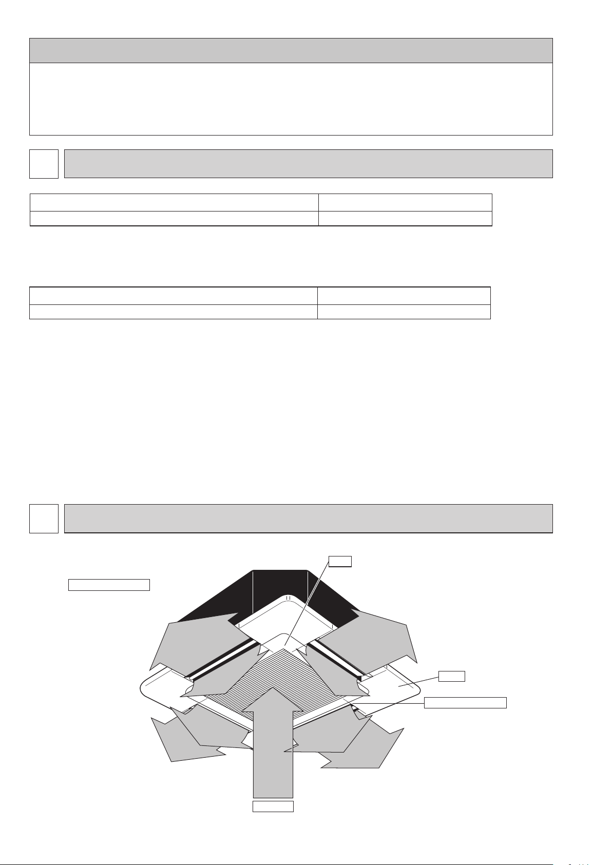
2-1. INDOOR UNIT
Horizontal Air Outlet
Sets horizontal airflow automatically
during cooling or dehumidifying.
Filter
Removes dust and pollutants
from drawn in air.
Grille
Auto Air Swing Vane
Disperses airflow up and
down and adjusts the angle
of airflow direction.
Air Intake
Draws in air from room.
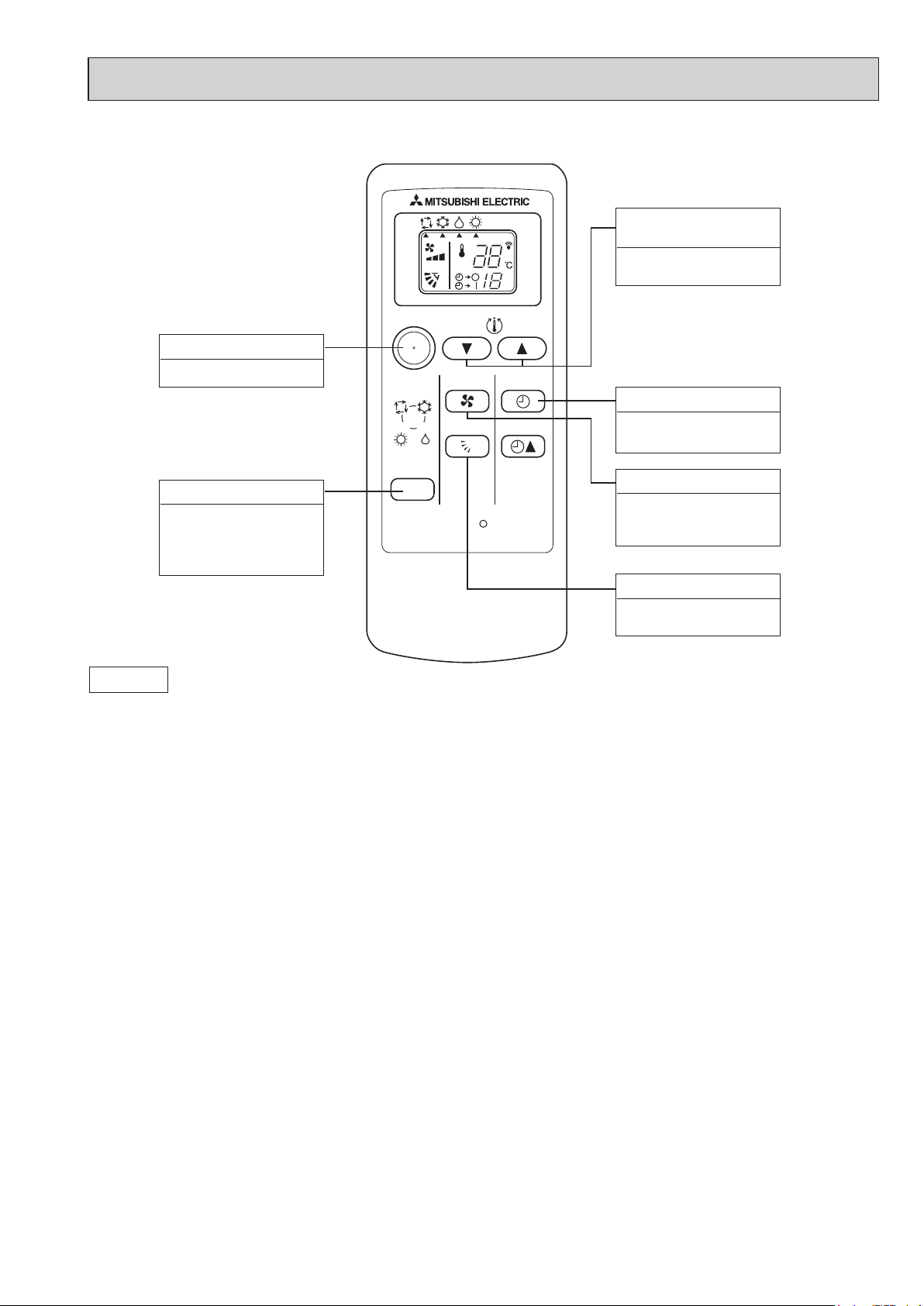
2-2. WIRELESS REMOTE CONTROLLER
OCH564
TEMPERATURE
SETTING button
To set any
h
temperature.
desired room
ON/OFF
TOO
WARM
TOO
COOL
ON / OFF button
To start and to stop operation.
MODE SELECT button
To change the operation
mode; Auto, Cooling ,
Heating and Drying . (SLZ)
AUTO COOL
DRY
HEAT
MODE
FAN
VANE
SELECT
TIME
RESET
TIMER SELECT button
To set time to start or stop
unit operation.
FAN SPEED button
To set fan speed to Low,
Medium or High.
VANE CONTROL button
To change the airflow
direction.
Attention:
• Avoid pushing buttons with fingernails and other sharp objects. Sharp objects may damage remote controller.
33
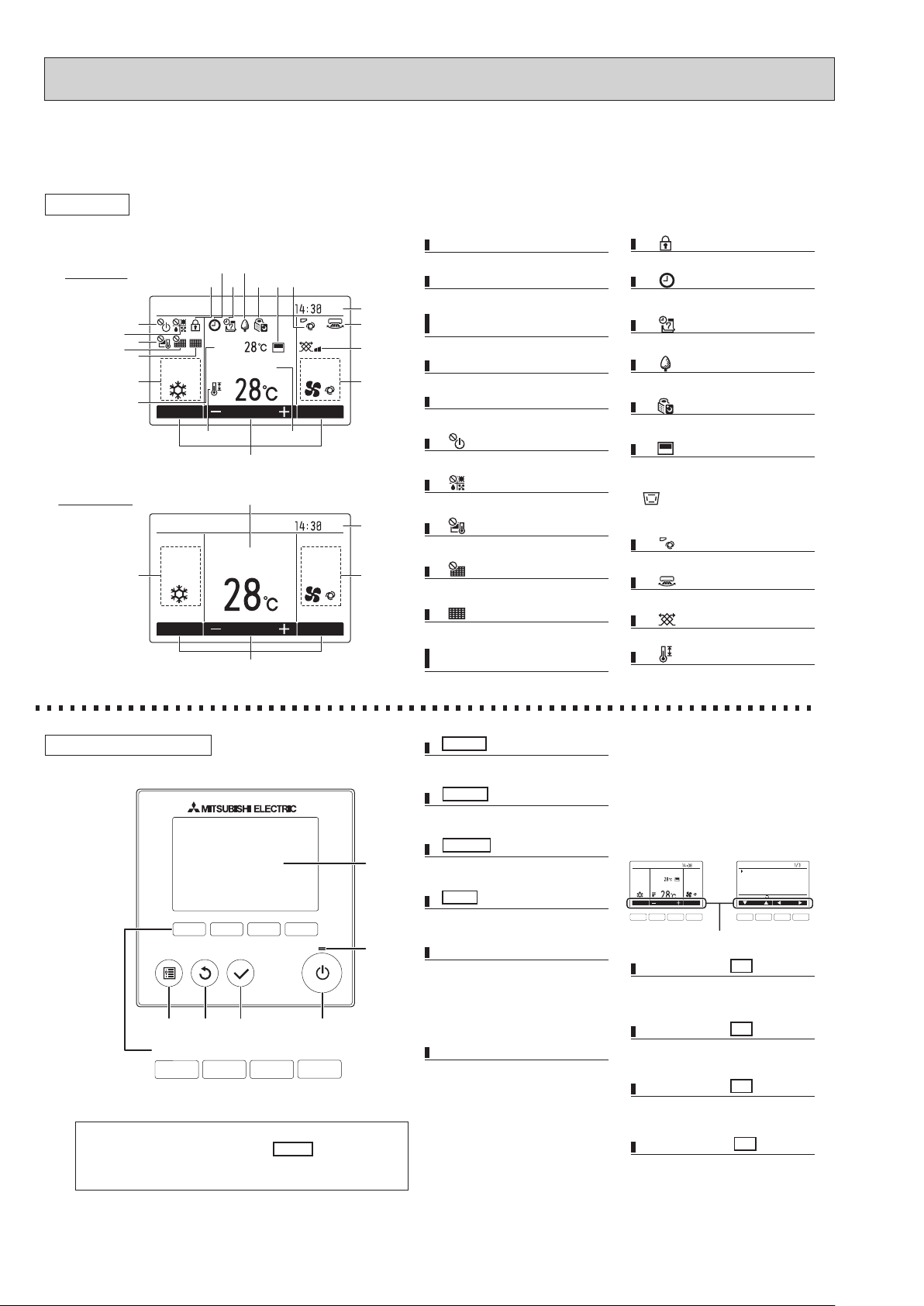
2-3. Wired remote controller (Option) PAR-31MAA
OCH564
The functions which can be used are restricted according to each model.
Display
Full mode
6
7
8
9
10
1
11
The main display can be displayed in two different modes: "Full" and "Basic."
The initial setting is "Full."
15
13
14
12
Room
Cool Auto
Mode Temp. Fan
Set temp.
21
Basic mode
Cool
1
Mode Temp. Fan
Note: All icons are displayed for explanation.
1 Operation mode
Indoor unit operation mode appears here.
181716
3
Fri
19
20
2 Preset temperature
Preset temperature appears here.
3 Clock
(See the Installation Manual.)
Current time appears here.
4 Fan speed
4
Fan speed setting appears here.
5 Button function guide
Functions of the corresponding buttons appear
2
5
here.
6
Appears when the ON/OFF operation is centrally
controlled.
7
2
3
Fri
AutoSet temp.
4
Appears when the operation mode is centrally
controlled.
8
Appears when the preset temperature is centrally
controlled.
9
Appears when the filter reset function is centrally
controlled.
10
Indicates when filter needs maintenance.
11 Room temperature
5
(See the Installation Manual.)
Current room temperature appears here.
12
Appears when the buttons are locked.
13
Appears when the On/Off timer or Night setback
function is enabled.
14
Appears when the Weekly timer is enabled.
15
Appears while the units are operated in the
energy-save mode.
16
Appears while the outdoor units are operated in
the silent mode.
17
Appears when the built-in thermistor on the
remote controller is activated to monitor the
room temperature (a).
appears when the thermistor on the
indoor unit is activated to monitor the room
temperature.
18
Indicates the vane setting.
19
Indicates the louver setting.
20
Indicates the ventilation setting.
21
Appears when the preset temperature range is
restricted.
Controller interface
*
1234
Function buttons
10987
• When the backlight is off, pressing any button turns the backlight on and
does not perform its function. (except for the ON/OFF button)
• Most settings (except ON/OFF, mode, fan speed, temperature) can be
made from the Menu screen.
1 ON/OFF button
Press to turn ON/OFF the indoor unit.
2 SELECT button
Press to save the setting.
3 RETURN button
5
Press to return to the previous screen.
4 MENU button
Press to bring up the Main menu.
6
5 Backlit LCD
Operation settings will appear.
When the backlight is off, pressing any
button turns the backlight on and it
will stay lit for a certain period of time
depending on the screen.
6 ON/OFF lamp
This lamp lights up in green while the unit
is in operation. It blinks while the remote
controller is starting up or when there is
an error.
The functions of the function buttons
change depending on the screen. Refer
to the button function guide that appears
at the bottom of the LCD for the functions
they serve on a given screen.
When the system is centrally controlled,
the button function guide that
corresponds to the locked button will not
appear.
Main display Main menu
Room
Set temp.
Cool Auto
Mode Temp. Fan
7 8 9 0 7 8 9 0
Function guide
Main
Fri
Main menu
Vane·Louver·Vent. (Lossnay)
High power
Timer
Weekly timer
OU silent mode
Main display:
Cursor Page
7 Function button F1
Main display: Press to change the operation
mode.
Main menu: Press to move the cursor down.
8 Function button F2
Main
display
Main menu: Press to move the cursor up.
: Press to decrease temperature.
9 Function button F3
Main
display
Main menu: Press to go to the previous page.
: Press to increase temperature.
10 Function button F4
Main
display
Main menu: Press to go to the next page.
: Press to change the fan speed.
4 5
Main menu list
OCH564
Setting and display items Setting details
Vane · Louver · Vent.
(Lossnay)
High power Use to reach the comfortable room temperature quickly.
Timer On/Off timer* Use to set the operation On/Off times.
Auto-Off timer Use to set the Auto-Off time.
Filter information Use to check the lter status.
Error information Use to check error information when an error occurs.
Weekly timer* Use to set the weekly operation On / Off times.
Energy saving Auto return Use to get the units to operate at the preset temperature after performing energy-save operation for a specied
Schedule* Set the start/stop times to operate the units in the energy-save mode for each day of the week, and set the
Night setback* Use to make Night setback settings.
Restriction Temp. range Use to restrict the preset temperature range.
Operation lock Use to lock selected functions.
Maintenance Auto descending panel Auto descending panel (Optional parts) Up / Down you can do.
Manual vane angle Use to set the vane angle for each vane to a xed position.
Initial setting Main/Sub When connecting two remote controllers, one of them needs to be designated as a sub controller.
Clock Use to set the current time.
Main display Use to switch between "Full" and "Basic" modes for the Main display.
Contrast Use to adjust screen contrast.
Initial setting Display details Make the settings for the remote controller related items as necessary.
Auto mode Whether or not to use the AUTO mode can be selected by using the button.
Administrator
word
Language selection Use to select the desired language.
Service Test run Select "Test run" from the Service menu to bring up the Test run menu.
Input maintenance Select "Input maintenance Info." from the Service menu to bring up the Maintenance information screen.
Function setting Make the settings for the indoor unit functions via the remote controller as necessary.
LOSSNAY setting
(City Multi only)
Check Error history: Display the error history and execute "delete error history".
Self check Error history of each unit can be checked via the remote controller.
Maintenance password Take the following steps to change the maintenance password.
Remote controller
check
* Clock setting is required.
pass-
Use to set the vane angle.
• Select a desired vane setting from ve different settings.
Use to turn ON / OFF the louver.
• Select a desired setting from "ON" and "OFF."
Use to set the amount of ventilation.
• Select a desired setting from "Off," "Low," and "High."
• Units can be operated in the High-power mode for up to 30 minutes.
• Time can be set in 5-minute increments.
• Time can be set to a value from 30 to 240 in 10-minute increments.
• The lter sign can be reset.
• Check code, error source, refrigerant address, unit model, manufacturing number, contact information (dealer's phone
number) can be displayed.
(The unit model, manufacturing number, and contact information need to be registered in advance to be displayed.)
• Up to eight operation patterns can be set for each day.
(Not valid when the On/Off timer is enabled.)
time period.
• Time can be set to a value from 30 and 120 in 10-minute increments.
(This function will not be valid when the preset temperature ranges are restricted.)
energy-saving rate.
• Up to four energy-save operation patterns can be set for each day.
• Time can be set in 5-minute increments.
• Energy-saving rate can be set to a value from 0% and 50 to 90% in 10% increments.
Select "Yes" to enable the setting, and "No" to disable the setting. The temperature range and the start/stop times can be set.
•
• Different temperature ranges can be set for different operation modes.
• The locked functions cannot be operated.
• The initial setting is "Full."
Clock: The initial settings are "Yes" and "24h" format.
Temperature: Set either Celsius (°C) or Fahrenheit (°F).
Room temp. : Set Show or Hide.
Auto mode: Set the Auto mode display or Only Auto display.
This setting is valid only when indoor units with the AUTO mode function are connected.
The administrator password is required to make the settings for the following items.
• Timer setting • Energy-save setting • Weekly timer setting
• Restriction setting • Outdoor unit silent mode setting • Night set back
• Test run • Drain pump test run
The following settings can be made from the Maintenance Information screen.
• Model name input • Serial No. input • Dealer information input
This setting is required only when the operation of City Multi units is interlocked with LOSSNAY units.
Refrigerant leak check: Refrigerant leaks can be judged.
Smooth maintenance: The indoor and outdoor maintenance data can be displayed.
Request cord: Details of the operation data including each thermistor temperature and error history can be checked.
When the remote controller does not work properly, use the remote controller checking function to troubleshoot the problem.
5
3
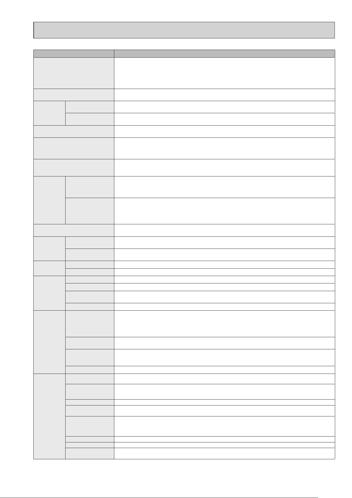
OCH564
SPECIFICATIONS
Indoor service ref.
Mode
Power supply (phase, cycle, voltage)
Input
Running current*
Dew prevention heater
Power factor*
Electrical
data
Fan motor output*
Airflow (Low/Midium/High)
K/h
Noise level (Low/Midium/High)
Width
snoisnemiD
Depth
Height
Weight
NOTE : Test conditions are based on ISO 5151.
Cooling : Indoor D.B. 27˚C W.B. 19˚C
Outdoor D.B. 35˚C W.B. 24˚C
Heating : Indoor D.B. 20˚C W.B. 15˚C
Outdoor D.B. 7˚C W.B. 6˚C
Refrigerant piping length (one way): 5m
*Measured under rated operating frequency
mm (in)
mm (in)
mm (in)
kW
A
W
%
kW
dB
kg
SLZ-KA25VAL3.TH(-ER)
Cooling Heating
Single phase
50 Hz, 230 V
0.05 0.03
0.37 0.26
0.014
59 51
0.05
480/540/660
29/33/38
SLZ-KA35VAL3.TH(-ER)
Cooling
Heating
Single phase
50 Hz, 230 V
0.05 0.03
0.37 0.26
0.014
59 51
0.05
480/540/660
29/33/38
UNIT: 570 (22-7/16) PANEL: 650 (25-9/16)
UNIT: 570 (22-7/16) PANEL: 650 (25-9/16)
UNIT: 235 (9-1/4) PANEL: 20 (13-13/16)
UNIT: 16 PANEL: 3
SLZ-KA50VAL3.TH(-ER)
Cooling
Heating
Single phase
50 Hz, 230 V
0.05 0.03
0.37 0.26
0.014
59 51
0.05
480/540/660
30/34/39
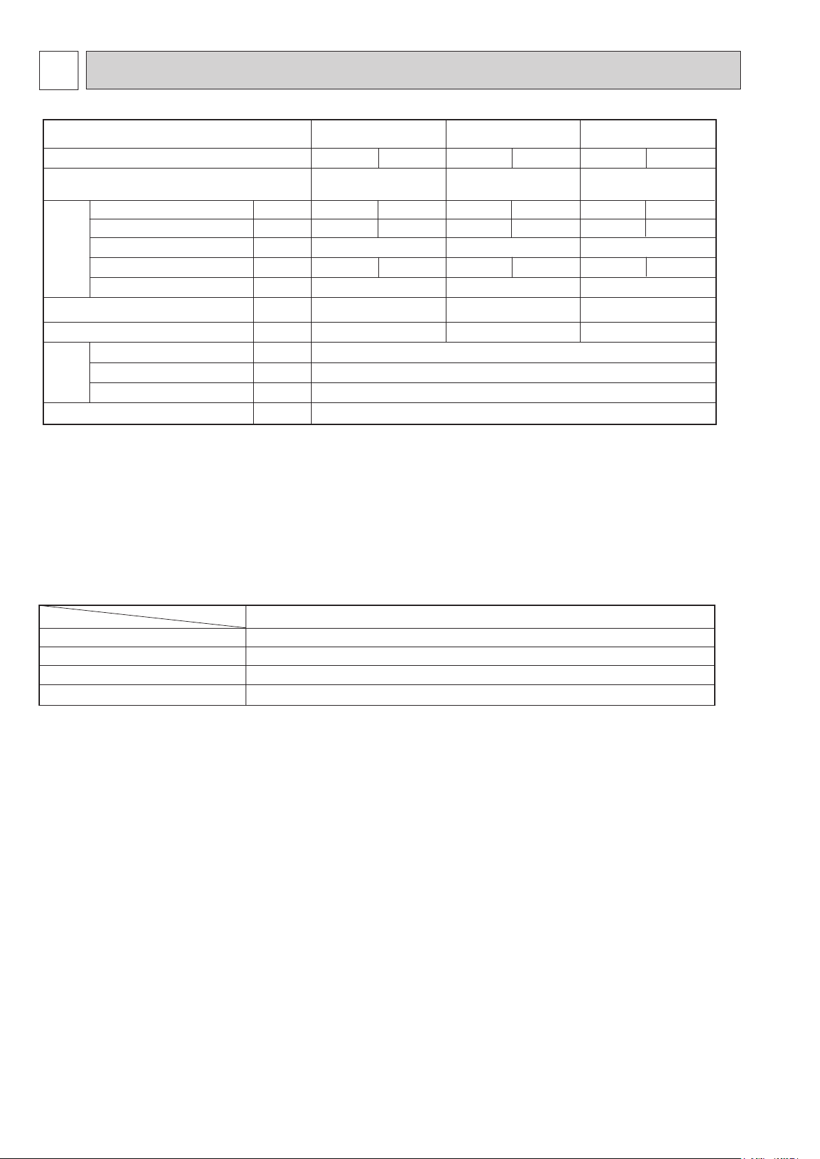
Specifications and rating conditions of main electric parts
INDOOR UNIT
Item
Fuse
Vane motor
Terminal block
Cord Heater
Service ref.
(FUSE)
(MV)
(TB)
(H2)
SLZ-KA25VAL3.TH(-ER)
TO OUTDOOR UNIT: 3P TO WIRED REMOTE CONTROLLER: 2P
SLZ-KA35VAL3.TH(-ER)
250V 6.3A
MSBPC20 12V 250"
240V AC 15W
SLZ-KA50VAL3.TH(-ER)
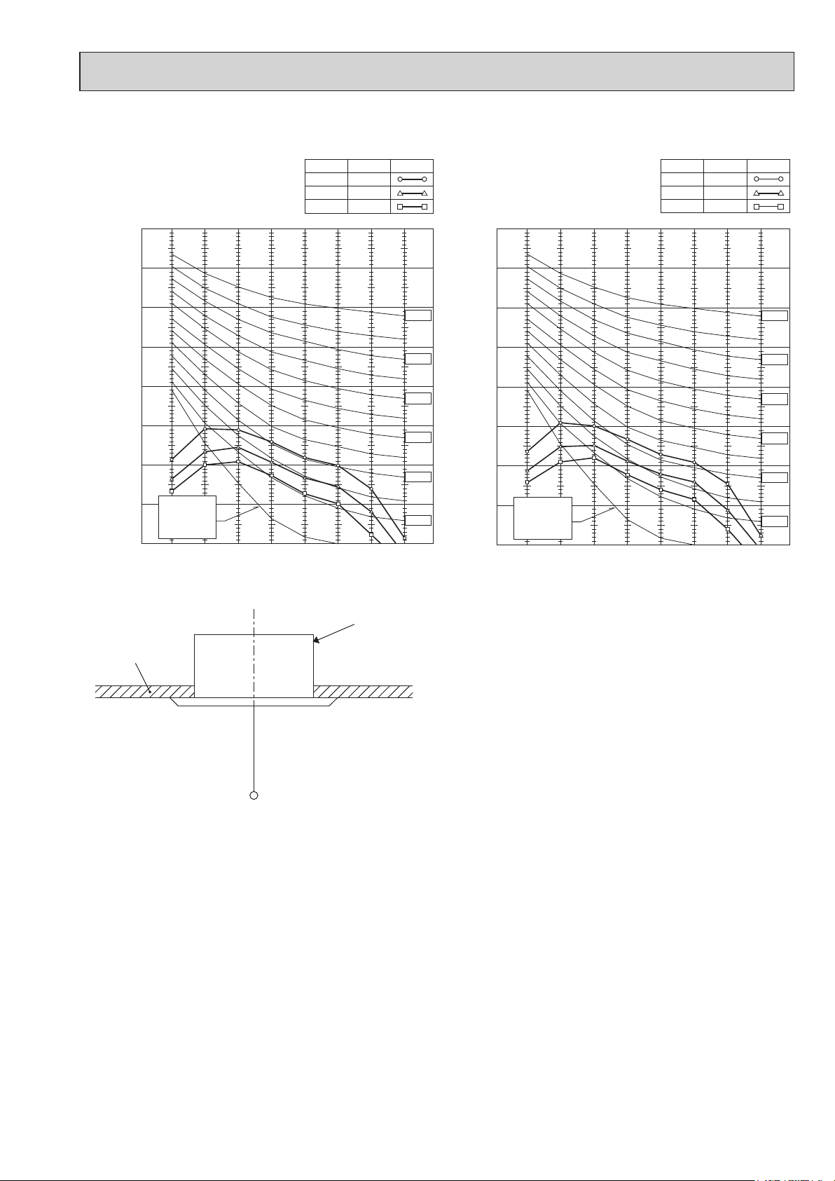
NOISE CRITERION CURVES
OCH564
SLZ-KA25VAL3.TH(-ER)
SLZ-KA35VAL3.TH(-ER)
NOTCH
High
Medium
Low
90
80
70
60
50
40
30
APPROXIMATE
20
THRESHOLD OF
OCTAVE BAND SOUND PRESSURE LEVEL, dB (0 dB = 0.0002 µbar)
HEARING FOR
CONTINUOUS
NOISE
10
63 125 250 500 1000 2000 4000 8000
BAND CENTER FREQUENCIES, Hz
<50Hz>
SPL(dB)33LINE
38
29
NC-70
NC-60
NC-50
NC-40
NC-30
NC-20
SLZ-KA50VAL3.TH(-ER)
NOTCH
High
Medium
Low
90
80
70
60
50
40
30
APPROXIMATE
20
THRESHOLD OF
OCTAVE BAND SOUND PRESSURE LEVEL, dB (0 dB = 0.0002 µbar)
HEARING FOR
CONTINUOUS
NOISE
10
63 125 250 500 1000 2000 4000 8000
BAND CENTER FREQUENCIES, Hz
<50Hz>
SPL(dB)34LINE
39
30
NC-70
NC-60
NC-50
NC-40
NC-30
NC-20
UNIT
CEILING
1.5m
MICROPHONE
NOTE: The sound level is measured in an anechoic room where echoes are few, when compressor stops. The sound
may be bigger than the indicated level in actual use due to surrounding echoes. The sound level can be higher
by about 2 dB than the indicated level during cooling and heating operation.
77
4
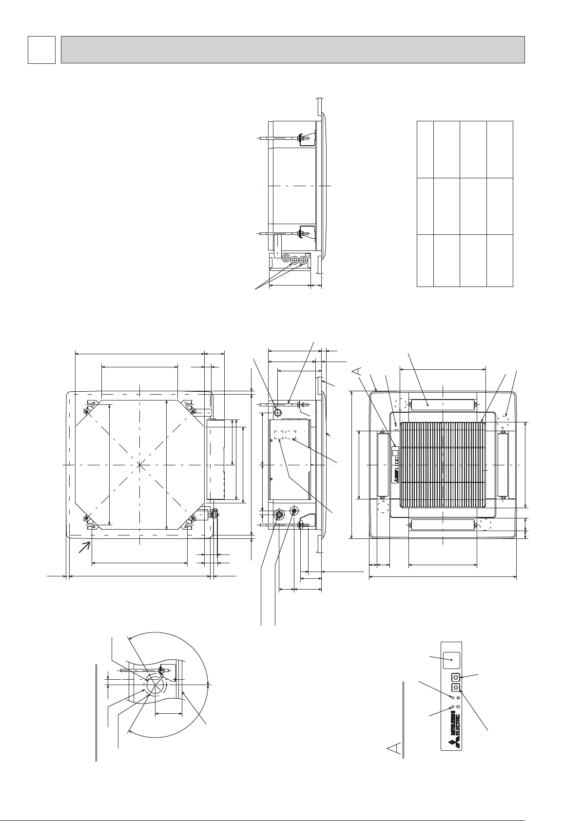
OCH564
OUTLINES AND DIMENSIONS
SLZ-KA25VAL3.TH
SLZ-KA35VAL3.TH
SLZ-KA50VAL3.TH
SLZ-KA25VAL3.TH-ER
SLZ-KA35VAL3.TH-ER
SLZ-KA50VAL3.TH-ER
570
335
Unit: mm
Refrigerent pipe
(gas)
flared connection
{ 9.52mm
Refrigerent pipe
(liquid)
flared connection
{ 6.35mm
Models
18248
Wiring entry
Suspension bolt
M10 or 3/8
(procure locally)
87
31
Drain pipe
VP-25 connection
(O.D. { 32)
235
208
193
20
0
Brand label
27
+5
Grille
Auto vane
Drain hole
SLZ-KA25VAL3
377
3/8 inch
flared connection
{ 9.52mm
1/4 inch
flared connection
{ 6.35mm
SLZ-KA35VAL3
Air intake hole
3/8 inch
{ 12.7mm
1/4 inch
{ 6.35mm
1/2 inch
flared connection
1/4 inch
flared connection
SLZ-KA50VAL3
Vane motor
Air intake grille
Fresh air
intake
530
Suspension bolt
pitch
Ceiling hole
{ 73.4
Cut out hole
570
Suspension bolt pitch
420
120
V/M
Ceiling surface
15~37 15~37576~620
352
335
Ceiling hole
576~620
15~37 15~37
230
17 202
66121
Refrigerent pipe (liquid)
Refrigerent pipe (gas)
199
56
57
Grille
301
650
Terminal block
Air outlet hole
Terminal block
(Case of Wired remote controller)
lower edge
Suspension bolt
93
38~58
V/M
55 35
Air outlet hole
301
650
Receiver
V/M
V/M
377
Air intake hole
35 55
25
{ 100
3- { 2.8 hole
Detail drawing of fresh air intake
Burring hole
Operation lamp
118
120
Ceiling surface
(WIRELESS PANEL)
DEFROST/STAND BY lamp
Emergency operation switch(cooling)
Emergency operation switch(heating)
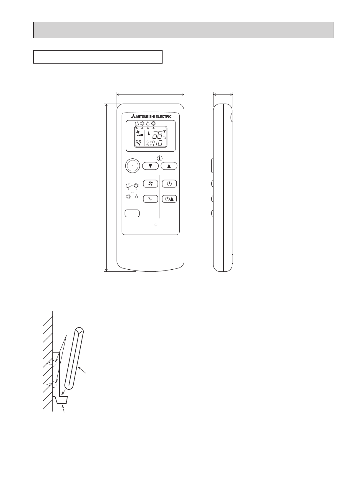
WIRELESS REMOTE CONTROLLER
OCH564
57 17.5
Unit: mm
h
B
D
C
A
140
ON/OFF
AUTO COOL
HEAT
MODE
DRY
TOO
WARM
FAN
VANE
TOO
COOL
SELECT
TIME
RESET
Installation area
• Area in which the remote controller is not exposed to direct sunlight
• Area in which there is no heating source nearby
• Area in which the remote controller is not exposed to cold (or hot) winds
• Area in which the remote controller can be operated easily
• Area in which the remote controller is beyond the reach of children
Installation method
1 Attach the remote controller holder to the desired location using 2 tapping screws.
2 Insert the lower end of the controller into the holder.
A Wireless remote controller (Accessory)
B Wall
C Remote controller holder (Accessory)
D Fixing screw (Accessory)
• The signal can travel up to approximately 7 meters (in a straight line) within 45
degrees to both right and left of the center line of the receiver.
In addition, the signal may not be received if there is interference of light of fluorescent
lights or strong sunlight.
99
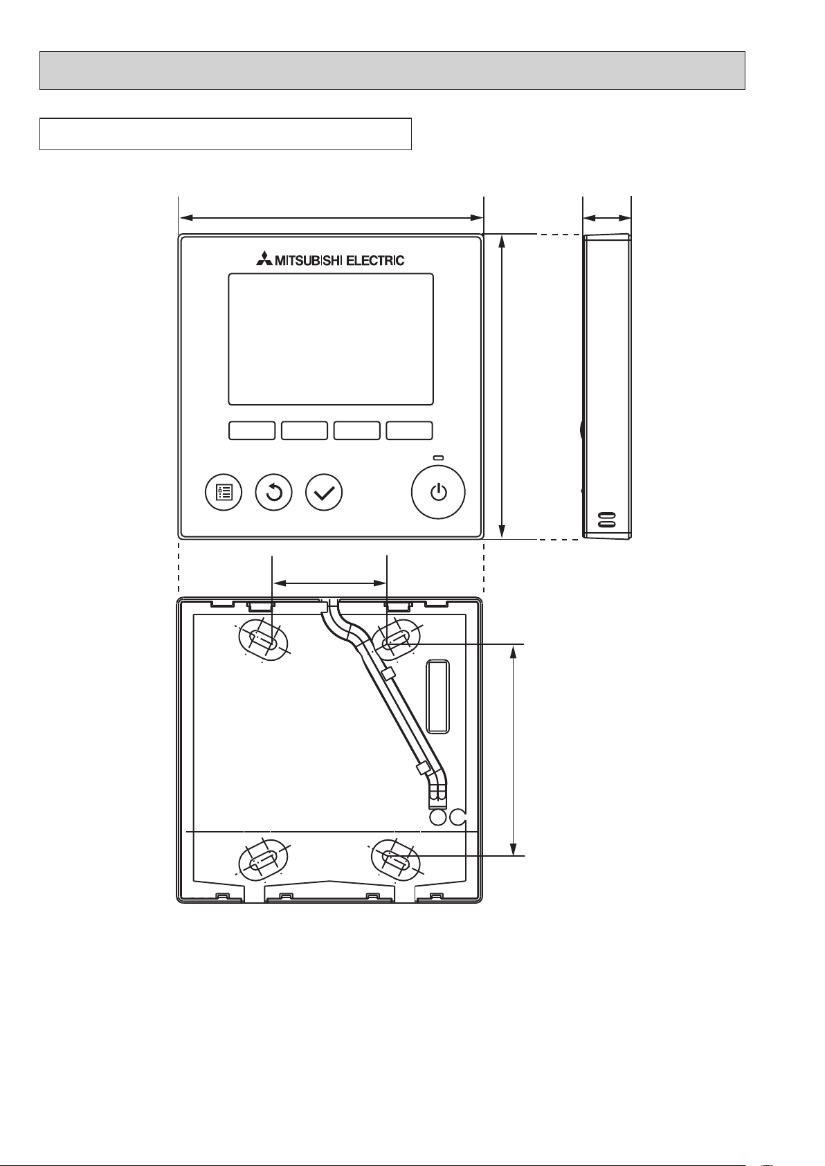
WIRED REMOTE CONTROLLER PAR-31MAA
OCH564
(Option)
Unit: mm
19120
120
46
83.5
 Loading...