

Mitsubishi SLZ-KA25VA(L), SLZ-KA35VA(L), SLZ-KA50VA(L) Service Manual
SPLIT-TYPE, HEAT PUMP AIR CONDITIONERS
ON/OFF
RESET
TOO
WARM
TOO
COOL
MODE
AUTO COOL
DRY
HEAT
FAN
VANE
SELECT
TIME
TECHNICAL & SERVICE MANUAL
No. OC320
Indoor unit
[Model names] [Service Ref.]
SLZ-KA25VA SLZ-KA25VA.TH
SLZ-KA35VA SLZ-KA35VA.TH
SLZ-KA50VA SLZ-KA50VA.TH
SLZ-KA25VAL SLZ-KA25VAL.TH
SLZ-KA35VAL SLZ-KA35VAL.TH
SLZ-KA50VAL SLZ-KA50VAL.TH
CONTENTS
Note :
•This manual does not cover
outdoor units. When servicing
outdoor units, please refer
to the service manual
No.OC322 together with this
manual.
1. PART NAMES AND FUNCTIONS ········2
2. SPECIFICATIONS·································5
3. OUTLINES AND DIMENSIONS············7
4. WIRING DIAGRAM·····························10
5.
Model name
indication
INDOOR UNIT
REFRIGERANT SYSTEM DIAGRAM
6. TROUBLESHOOTING ························12
7. 4-WAY AIR FLOW SYSTEM ···············19
·······11
8. DISASSEMBLY PROCEDURE ···········21
9. PARTS LIST········································24
TEMP.
SLZ-KA25,35,50VAL.TH SLZ-KA25,35,50VA.TH
REMOTE CONTROLLER
ON/OFF
1
ON/OFF
RESET
TOO
WARM
TOO
COOL
MODE
AUTO COOL
DRY
HEAT
FAN
VANE
SELECT
TIME
h
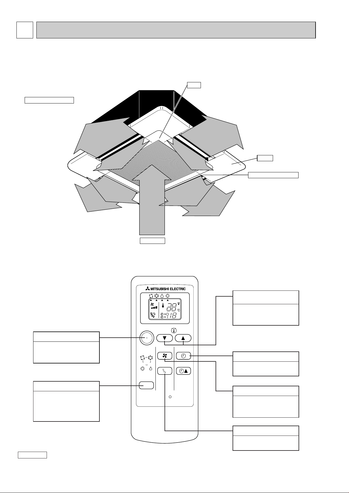
PART NAMES AND FUNCTIONS
Indoor Unit
SLZ-KA25VAL.TH SLZ-KA25VA.TH
SLZ-KA35VAL.TH SLZ-KA35VA.TH
SLZ-KA50VAL.TH SLZ-KA50VA.TH
Horizontal Air Outlet
Sets airflow horizontal automatically
during cooling or dehumidifying.
Filter
Remove dust and pollutants
from inhaled air
Grille
Auto Air Swing Vane
Disperses airflow up and
down and adjusts the angle
of airflow direction.
Air Intake
Inhales air from room.
Wireless remote controller
SLZ-KA25VAL.TH
SLZ-KA35VAL.TH
SLZ-KA50VAL.TH
ON / OFF button
Pushing button starts
operation. Pushing again
stops operation.
MODE SELECT button
This button is used to change
between auto, cooling,
heating and drying operation
modes. (SLZ)
Attention :
● Avoid operation of buttons with fingernails or other sharp objects. Sharp objects may scratch remote controller.
SET TEMPERATURE
button
SET TEMPERATURE
button sets and any
desired room temperature.
TIMER SELECT button
Used for selecting timed
starting or stopping.
FAN SPEED button
This button is used to set
fan speed to low, medium
or high.
VANE CONTROL button
Used to change the airflow
direction.
2
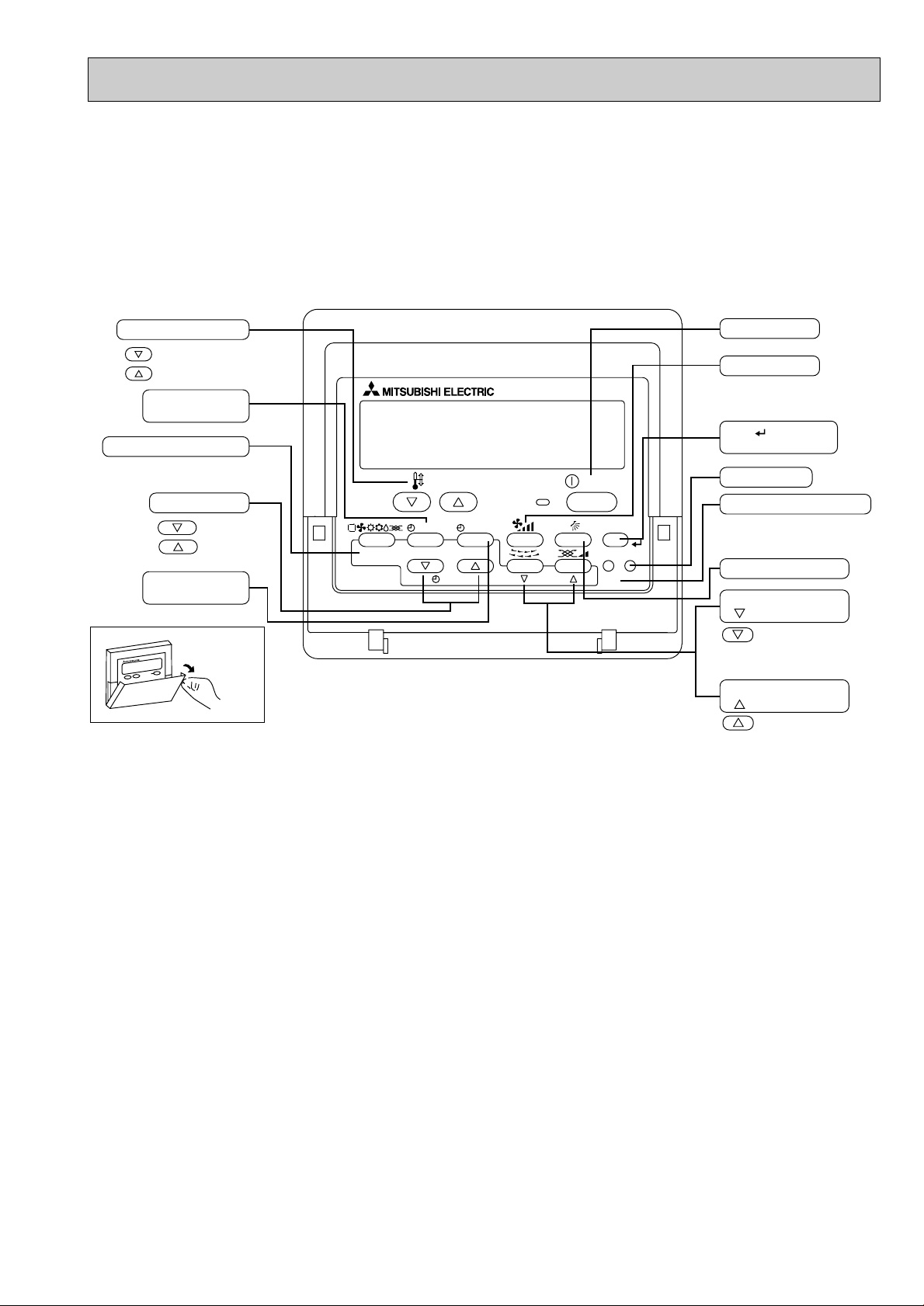
Wired remote controller
PAR-21MAA
ON/OFF
FILTER
CHECK
OPERATION
CLEAR
TEST
TEMP.
MENU
BACK DAY
MONITOR/SET
CLOCK
ON/OFF
Set Temperature buttons
Down
Up
Timer Menu button
(Monitor/Set button)
Mode button (Return button)
Set Time buttons
Back
Ahead
Timer On/Off button
(Set Day button)
Opening the
door.
Start/Stop button
Fan Speed button
Filter button
(<return sign> button)
Test Run button
Service button (Clear button)
Airflow Up/Down button
Louver button
( Operation button)
To preceding operation
number.
Ventilation button
(
Operation button)
To next operation number.
Once the controls are set, the same operation mode can be repeated by simply pressing the ON/OFF button.
SLZ-KA25VA.TH
SLZ-KA35VA.TH
SLZ-KA50VA.TH
● Operation buttons [ PAR-21MAA ]
3
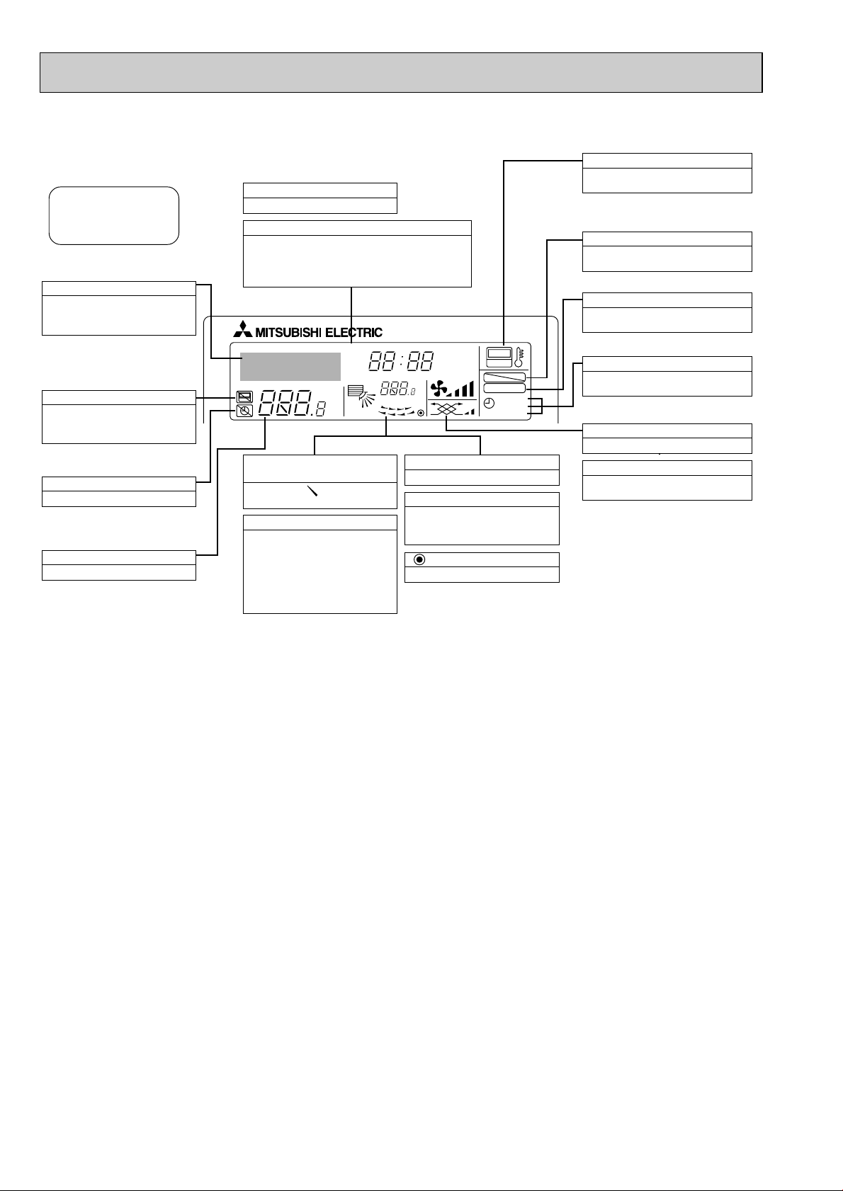
● Display
For purposes of this explanation,
all parts of the display are shown
as lit. During actual operation, only
the relevant items will be lit.
˚F˚C
˚F˚C
ERROR CODE
AFTER
TIMER
TIME SUN MON TUE WED THU FRI SAT
ON
OFF
Hr
AFTER
FILTER
FUNCTION
ONLY1Hr.
WEEKLY
SIMPLE
AUTO OFF
Identifies the current operation
Shows the operating mode, etc.
* Multilanguage display is sup-
ported.
“Centrally Controlled” indicator
Indicates that operation of the remote controller has been prohibited by a master controller.
“Timer Is Off” indicator
Indicates that the timer is off.
Temperature Setting
Shows the target temperature.
Day-of-Week
Shows the current day of the week.
Time/Timer Display
Shows the current time, unless the simple or Auto Off
timer is set.
If the simple or Auto Off timer is set, shows the time
remaining.
“Sensor” indication
Displayed when the remote controller
sensor is used.
“Locked” indicator
Indicates that remote controller buttons have been locked.
“Clean The Filter” indicator
Comes on when it is time to clean the
filter.
Timer indicators
The indicator comes on if the corresponding timer is set.
Up/Down Air Direction indicator
The indicator shows the direction of the outcoming airflow.
“One Hour Only” indicator
Displayed if the airflow is set to
weak and downward during COOL
or DRY mode. (Operation varies
according to model.)
The indicator goes off after one
hour, at which time the airflow direction also changes.
Room Temperature display
Shows the room temperature.
Louver display
Indicates the action of the swing
louver. Does not appear if the
louver is stationary.
(Power On indicator)
Indicates that the power is on.
Fan Speed indicator
Shows the selected fan speed.
Ventilation indicator
Appears when the unit is running in
Ventilation mode.
Caution
● Only the Power display lights when the unit is stopped and power supplied to the unit.
● When power is turned ON for the first time the (Centrally controlled) display appears to go off momentarily but this is not a
malfunction.
● “NOT AVAILABLE” is displayed when the Air speed button are pressed.This indicates that this room unit is not equipped
with the fan direction adjustment function and the louver function.
● When power is turned ON for the first time, it is normal that “PLEASE WAIT” is displayed on the room temperature indication (For max. 2minutes). Please wait until this “PLEASE WAIT” indication disappear then start the operation.
4
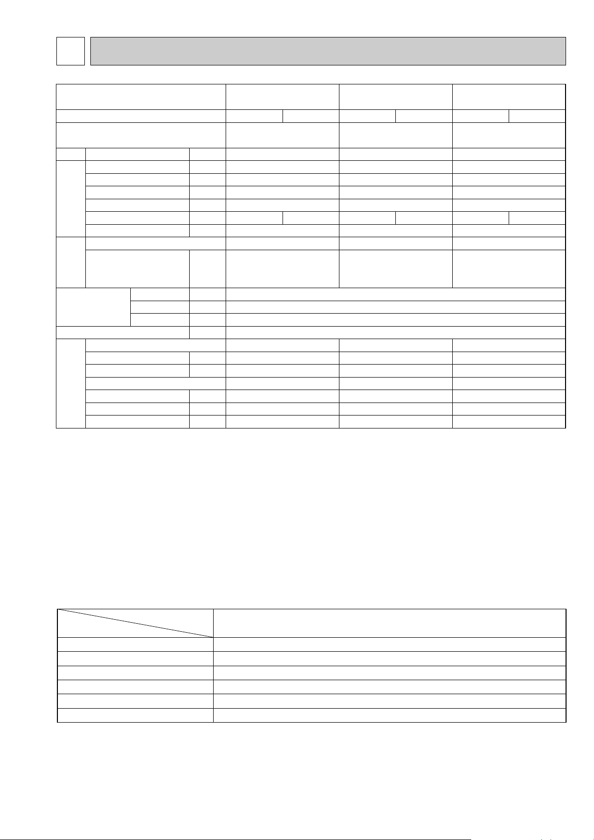
2
SLZ-KA25VAL.TH
SLZ-KA25VA.TH
SLZ-KA35VAL.TH
SLZ-KA35VA.TH
Indoor model
Function
Power supply
Single phase
230V, 50Hz
600/540/480
10
0.35
75
0.014
0.19
PK6V15-LD
4
37/31/28
650/530/480
3
10
10
10
Cooling
90
Heating
93
Single phase
230V, 50Hz
660/540/480
10
0.40
85
0.014
0.26
PK6V20-LL
4
38/33/29
690/570/510
3
10
10
10
Cooling
94
Heating
94
Air flow
(High/Medium/Low)
Power outlet
Running current ✽1
Power input Rated frequency
Dew prevention heater
Power factor ✽1
Fan motor current ✽1
Model
Winding
resistance (at20:)
Width
Height
Depth
Weight
Air direction
Sound level(High/Medium/Low)
Fan speed(High/Medium/Low)
Fan speed regulator
Thermistor TH1(at25:)
Thermistor TH2(at25:)
Thermistor TH5(at25:)
K /h
A
A
W
(kW)
%
A
"
mm(in)
mm(in)
mm(in)
kg
dB(A)
rpm
k"
k"
k"
Electrical
data
Fan
motor
Special
remarks
Capacity
Dimensions
WHT-BLK : 407 BLK-BLU : 86
BLU-YLW : 30
BRN-RED : 165
UNIT : 570(22-7/16) PANEL : 650(25-9/16)
UNIT : 208(8-3/16) PANEL : 20(13/16)
UNIT : 570(22-7/16) PANEL : 650(25-9/16)
UNIT : 16.5 PANEL : 3
WHT-BLK : 393 BLK-BLU : 164
BLU-YLW : 47
BRN-RED : 319
SLZ-KA50VAL.TH
SLZ-KA50VA.TH
Single phase
230V, 50Hz
660/540/480
20
0.65
85
0.014
0.27
PK6V20-LM
4
39/34/30
710/590/530
3
10
10
10
Cooling
97
Heating
97
WHT-BLK : 325 BLK-BLU : 143
BLU-YLW : 47
BRN-RED : 309
1.5+ 440V
250V 6.3A
MSBPC20 12V 250"
TO OUTDOOR UNIT : 3P TO WIRED REMOTE CONTROLLER : 2P (SLZ-KA25/35/50VA.TH)
145:i2:
240V AC 15W
INDOOR UNIT
Item
Model
Indoor fan capacitor
Fuse
Vane motor
Terminal block
Indoor fan motor thermal fuse
Cord Heater
SLZ-KA25VAL.TH SLZ-KA35VAL.TH SLZ-KA50VAL.TH
(C1)
(FUSE)
(MV)
(TB)
(H2)
SLZ-KA25VA.TH SLZ-KA35VA.TH SLZ-KA50VA.TH
SPECIFICATIONS
NOTE : Test conditions are based on ISO 5151
Cooling : Indoor D.B. 27: W.B. 19:
Heating : Indoor D.B. 20: W.B. 15:
Refrigerant piping length (one way): 5m
✽1 Measured under rated operating frequency.
Specifications and rating conditions of main electric parts
Outdoor D.B. 35: W.B. 24:
Outdoor D.B. 7: W.B. 6:
5
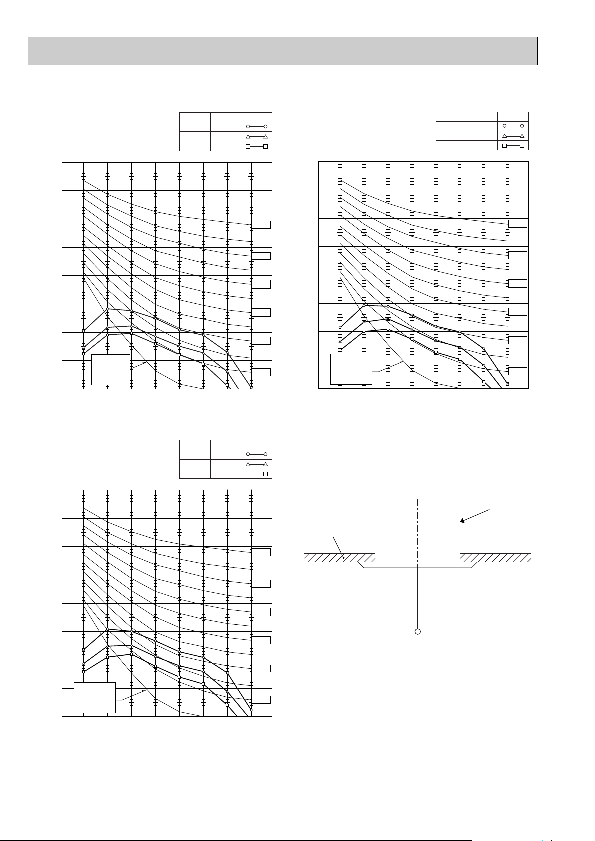
90
80
70
60
50
40
30
20
10
63 125 250 500 1000 2000 4000 8000
APPROXIMATE
TERESHOLD OF
HEARING FOR
CONTINUOUS
NOISE
NC-60
NC-50
NC-40
NC-30
NC-20
NC-70
OCTAVE BAND SOUND PRESSURE LEVEL, dB (0 dB = 0.0002 µbar)
BAND CENTER FREQUENCIES, Hz
SLZ-KA35VAL.TH
SLZ-KA35VA.TH
High
Medium
38
SPL(dB)33LINE
<50Hz>
NOTCH
Low
29
90
80
70
60
50
40
30
20
10
63 125 250 500 1000 2000 4000 8000
APPROXIMATE
TERESHOLD OF
HEARING FOR
CONTINUOUS
NOISE
NC-60
NC-50
NC-40
NC-30
NC-20
NC-70
OCTAVE BAND SOUND PRESSURE LEVEL, dB (0 dB = 0.0002 µbar)
BAND CENTER FREQUENCIES, Hz
SLZ-KA25VAL.TH
SLZ-KA25VA.TH
High
Medium
37
SPL(dB)31LINE
<50Hz>
NOTCH
Low
28
NOISE CRITERION CURVES
UNIT
1.5m
MICROPHONE
CEILING
90
80
70
60
50
40
30
20
10
63 125 250 500 1000 2000 4000 8000
APPROXIMATE
TERESHOLD OF
HEARING FOR
CONTINUOUS
NOISE
NC-60
NC-50
NC-40
NC-30
NC-20
NC-70
OCTAVE BAND SOUND PRESSURE LEVEL, dB (0 dB = 0.0002 µbar)
BAND CENTER FREQUENCIES, Hz
SLZ-KA50VAL.TH
SLZ-KA50VA.TH
High
Medium
39
SPL(dB)34LINE
<50Hz>
NOTCH
Low
30
6
NOTE: The sound level is measured in an anechoic room where echoes are few, when compressor stops. The sound
may be bigger than displayed level under actual installation condition by surrounding echoes. The sound level
can be higher by about 2 dB than the displayed level during cooling and heating operation.
3
SLZ-KA50VA(L)
SLZ-KA35VA(L)
SLZ-KA25VA(L)
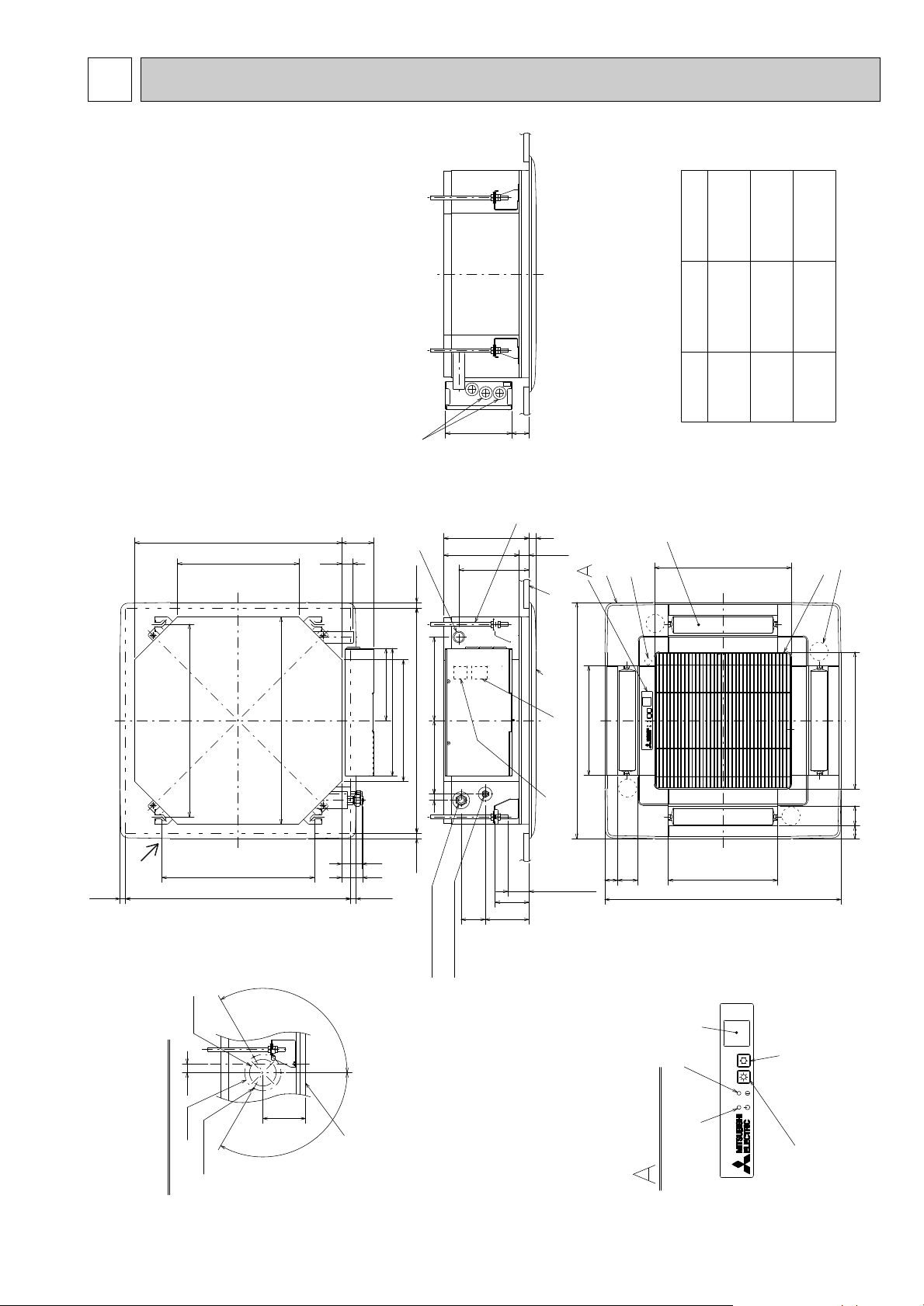
Brand label
(Case of Wired remote controller)
Terminal block
Terminal block
87
Suspension bolt
M10 or 3/8
(procure locally)
1/4F
flared connection
{ 6.35mm
1/4F
flared connection
{ 6.35mm
{ 9.52mm
flared connection
3/8F
1/2F
flared connection
Refrigerent pipe (liquid)
Refrigerent pipe (gas)
Models
{ 6.35mm
flared connection
1/4F
Refrigerent pipe
(liquid)
Refrigerent pipe
(gas)
{ 12.7mm
{ 9.52mm
flared connection
3/8F
15~37 15~37
576~620
570
530
Grille
Fresh air
intake
Drain pipe
VP-25 connection
(O.D. { 32)
Vane motor
Drain hole
V/M
Air intake grille
55 35
35 55
Auto vane
Grille
Air intake hole
Air intake hole
Air outlet hole
Air outlet hole
301
301
Emergency operation switch(cooling)
Emergency operation switch(heating)
Operation lamp
DEFROST/STAND BY lamp
(WIRELESS PANEL)
Receiver
Detail drawing of fresh air intake
Ceiling surface
Cut out hole
{ 73.4
Burring hole
3- { 2.8 hole
{ 100
118
25
120°
120°
377
377
650
650
Suspension bolt
lower edge
230
18248
Wiring entry
Ceiling surface
235
208
27
+5
0
193
20
93
38~58
66121
17 202
56
57
31
Ceiling hole
Suspension bolt pitch
15~37 15~37576~620
420
570
335
199
352
335
Suspension bolt
pitch
Ceiling hole
V/M
V/M
V/M
OUTLINES AND DIMENSIONS
SLZ-KA25VAL.TH
SLZ-KA35VAL.TH
SLZ-KA50VAL.TH
SLZ-KA25VA.TH
SLZ-KA35VA.TH
SLZ-KA50VA.TH
Unit : mm
7
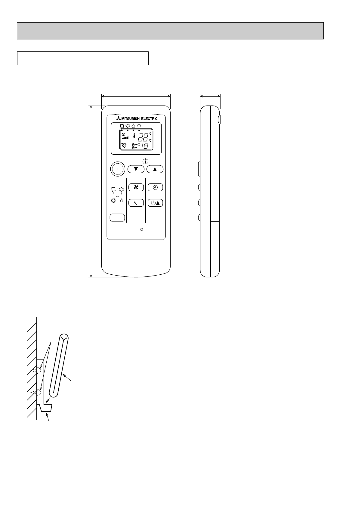
WIRELESS REMOTE CONTROLLER
Installation area
• Area in which the remote controller is not exposed direct sunshine.
• Area in which there is no nearby heating source.
• Area in which the remote controller is not exposed to cold (or hot) winds.
• Area in which the remote controller can be operated easily
• Area in which the remote controller is beyond the reach of children.
Installation method
1 Attach the remote controller holder to the desired location using two tapping screws.
2 Place the lower end of the controller into the holder.
A Wireless remote controller (Accessory)
B Wall
C Remote controller holder (Accessory)
D Fixing screw (Accessory)
• The signal can travel up to approximately 7 meters (in a straight line) within 45
degrees to both right and left of the center line of the receiver.
In addition, the signal may not be received if there is interference of light of fluorescent
lights or strong sunlight.
A
C
B
D
ON/OFF
RESET
TOO
WARM
TOO
COOL
MODE
AUTO COOL
DRY
HEAT
FAN
VANE
SELECT
TIME
h
57 17.5
140
Unit : mm
8
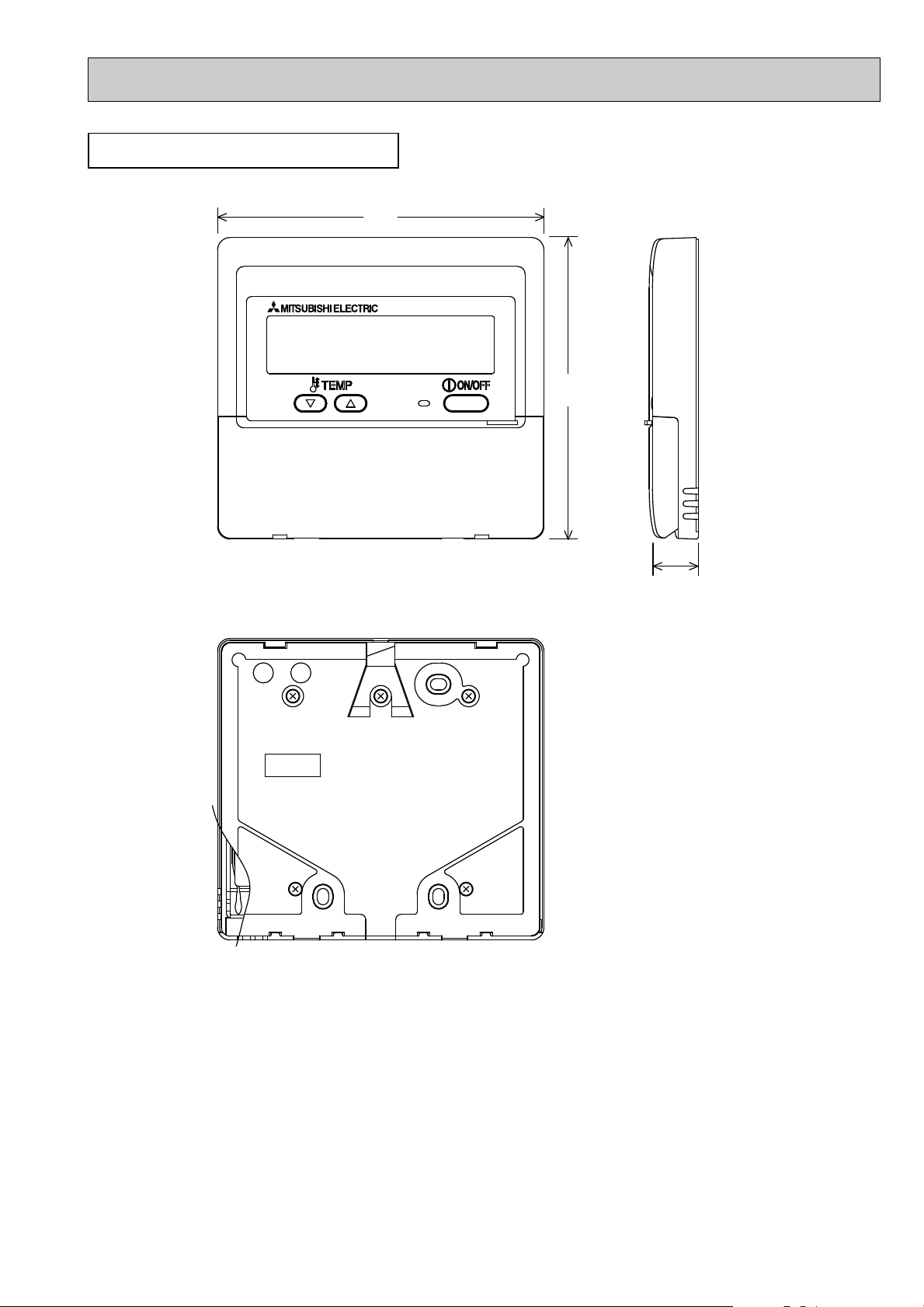
WIRED REMOTE CONTROLLER
130
120
19
Unit : mm
9
 Loading...