

Page 1
SPLIT-TYPE, HEAT PUMP AIR CONDITIONERS
ON/OFF
RESET
TOO
WARM
TOO
COOL
MODE
AUTO COOL
DRY
HEAT
FAN
VANE
SELECT
TIME
h
TECHNICAL & SERVICE MANUAL
No. OC302
Series SLZ
Ceiling Cassettes
R410A
Indoor unit
[Model names] [Service Ref.]
SLZ-A09AR SLZ-A09AR.TH
SLZ-A12AR SLZ-A12AR.TH
SLZ-A18AR SLZ-A18AR.TH
•This manual does not cover
outdoor units. When servicing
them, please refer to the
service manual No.OC304
and this manual in a set.
CONTENTS
1. PART NAMES AND FUNCTIONS ········2
2. SPECIFICATIONS·································3
3. OUTLINES AND DIMENSIONS············5
4. WIRING DIAGRAM ·······························7
5.
REFRIGERANT SYSTEM DIAGRAM
INDOOR UNIT
6. TROUBLESHOOTING ··························9
7. 4-WAY AIR FLOW SYSTEM ···············16
8. DISASSEMBLY PROCEDURE ···········18
9. PARTS LIST········································21
REMOTE CONTROLLER
·········8
Page 2
1
ON/OFF
RESET
TOO
WARM
TOO
COOL
MODE
AUTO COOL
DRY
HEAT
FAN
VANE
SELECT
TIME
h
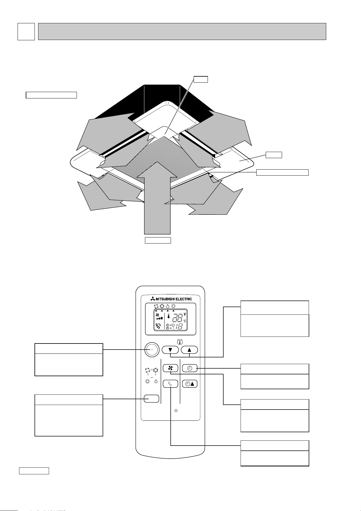
PART NAMES AND FUNCTIONS
Indoor Unit
SLZ-A09AR.TH
SLZ-A12AR.TH
SLZ-A18AR.TH
Horizontal Air Outlet
Sets airflow horizontal automatically
during cooling or dehumidifying.
Filter
Remove dust and pollutants
from inhaled air
Grille
Auto Air Swing Vane
Disperses airflow up and
down and adjusts the angle
of airflow direction.
Air Intake
Inhales air from room.
Remote controller
SET TEMPERATURE
button
SET TEMPERATURE
button sets and any
desired room temperature.
ON / OFF button
Pushing button starts
operation. Pushing again
stops operation.
MODE SELECT button
This button is used to change
between auto, cooling,
heating and drying operation
modes. (SLZ)
Attention :
● Avoid operation of buttons with fingernails or other sharp objects. Sharp objects may scratch remote controller.
TIMER SELECT button
Used for selecting timed
starting or stopping.
FAN SPEED button
This button is used to set
fan speed to low, medium
or high.
VANE CONTROL button
Used to change the airflow
direction.
2
Page 3
2
SLZ-A09AR.TH SLZ-A12AR.TH
Indoor model
Function
Power supply
Single phase
230V, 50Hz
600/540/480
10
0.18
40
0.014
0.18
PK6V15-LA
4
38/35/32
650/580/530
3
10
10
10
MPPC
Cooling
91
Heating
92
Single phase
230V, 50Hz
660/600/540
10
0.23
52
0.014
0.23
PK6V20-LE
4
39/37/34
690/630/570
3
10
10
10
MPPC
Cooling
94
Heating
95
Air flow (High/Med./Low)
Power outlet
Running current ✽1
Power input Rated frequency
Dew prevention heater
Power factor ✽1
Fan motor current ✽1
Model
Winding
resistance (at20:)
Width
Height
Depth
Weight
Air direction
Sound level(High/Med./Low)
Fan speed(High/Med./Low)
Fan speed regulator
Thermistor RT11(at25:)
Thermistor RT12(at25:)
Thermistor RT13(at25:)
Remote controller model
K /h
A
A
W
(kW)
%
A
"
mm(in)
mm(in)
mm(in)
kg
dB(A)
rpm
k"
k"
k"
Electrical
data
Fan
motor
Special
remarks
Capacity
Dimensions
WHT-BLK : 407 BLK-BLU : 55
BLU-YLW : 31 YLW-BRN : 30
BRN-RED : 165
UNIT : 570(22-7/16) PANEL : 650(25-9/16)
UNIT : 208(8-3/16) PANEL : 20(13/16)
UNIT : 570(22-7/16) PANEL : 650(25-9/16)
UNIT : 16.5 PANEL : 3
WHT-BLK : 384 BLK-BLU : 111
BLU-YLW : 49 YLW-BRN : 46
BRN-RED : 311
SLZ-A18AR.TH
Single phase
230V, 50Hz
660/600/540
20
0.24
53
0.014
0.24
PK6V20-LF
4
40/38/35
710/650/590
3
10
10
10
MPPC
Cooling
97
Heating
97
WHT-BLK : 317 BLK-BLU : 88
BLU-YLW : 52 YLW-BRN : 45
BRN-RED : 301
1.5+ 440V
250V 3.15A
MSBPC20 12V 250"
POWER SUPPLY : 3P TO OUTDOOR UNIT : 4P
G4A-1A-E-PS 12V DC
145:i2:
240V AC 15W
INDOOR UNIT
Item
Model
Indoor fan capacitor
Fuse
Vane motor
Terminal block
Contactor
Indoor fan motor thermal fuse
Cord Heater
SLZ-A09AR.TH SLZ-A12AR.TH SLZ-A18AR.TH
(C1)
(F11)
(MV)
(TB)
(52C)
(H2)
SPECIFICATIONS
NOTE : Test conditions are based on ISO 5151
Cooling : Indoor D.B. 27: W.B. 19:
Heating : Indoor D.B. 20: W.B. 15:
Refrigerant piping length (one way): 5m
✽1 Measured under rated operating frequency.
Specifications and rating conditions of main electric parts
Outdoor D.B. 35: W.B. 24:
Outdoor D.B. 7: W.B. 6:
3
Page 4
90
80
70
60
50
40
30
20
10
63 125 250 500 1000 2000 4000 8000
APPROXIMATE
TERESHOLD OF
HEARING FOR
CONTINUOUS
NOISE
NC-60
NC-50
NC-40
NC-30
NC-20
NC-70
OCTAVE BAND SOUND PRESSURE LEVEL, dB (0 dB = 0.0002 µbar)
BAND CENTER FREQUENCIES, Hz
SLZ-A12AR.TH
Hi
Me
39
SPL(dB)37LINE
<50Hz>
NOTCH
Lo
34
90
80
70
60
50
40
30
20
10
63 125 250 500 1000 2000 4000 8000
APPROXIMATE
TERESHOLD OF
HEARING FOR
CONTINUOUS
NOISE
NC-60
NC-50
NC-40
NC-30
NC-20
NC-70
OCTAVE BAND SOUND PRESSURE LEVEL, dB (0 dB = 0.0002 µbar)
BAND CENTER FREQUENCIES, Hz
SLZ-A09AR.TH
Hi
Me
38
SPL(dB)35LINE
<50Hz>
NOTCH
Lo
32
NOISE CRITERION CURVES
UNIT
1.5m
MICROPHONE
CEILING
90
80
70
60
50
40
30
20
10
63 125 250 500 1000 2000 4000 8000
APPROXIMATE
TERESHOLD OF
HEARING FOR
CONTINUOUS
NOISE
NC-60
NC-50
NC-40
NC-30
NC-20
NC-70
OCTAVE BAND SOUND PRESSURE LEVEL, dB (0 dB = 0.0002 µbar)
BAND CENTER FREQUENCIES, Hz
SLZ-A18AR.TH
Hi
Me
40
SPL(dB)38LINE
<50Hz>
NOTCH
Lo
35
4
NOTE: The sound level is measured in an anechoic room where echoes are few, when compressor stops. The sound
may be bigger than displayed level under actual installation condition by surrounding echoes. The sound level
can be higher by about 2 dB than the displayed level during cooling and heating operation.
Page 5
3
Suspension bolt
M10 or 3/8
(procure locally)
1/4F
flared connection
[6.35mm
1/4F
flared connection
[6.35mm
[9.52mm
flared connection
3/8F
1/2F
flared connection
SLZ-A18AR
SLZ-A12AR
Refrigerent pipe (liquid)
Refrigerent pipe (gas)
Models
SLZ-A09AR
[6.35mm
flared connection
1/4F
Refrigerent pipe
(liquid)
Refrigerent pipe
(gas)
[12.7mm
[9.52mm
flared connection
3/8F
15~37 15~37
576~620
570
530
Grille
Fresh air
intake
Drain pipe
VP-25 connection
(O.D.[32)
Vane motor
Drain hole
V/M
V/M
V/M
V/M
Air intake grille
55 35
35 55
Auto vane
Grille
Air intake hole
Air intake hole
Air outlet hole
Air outlet hole
301
301
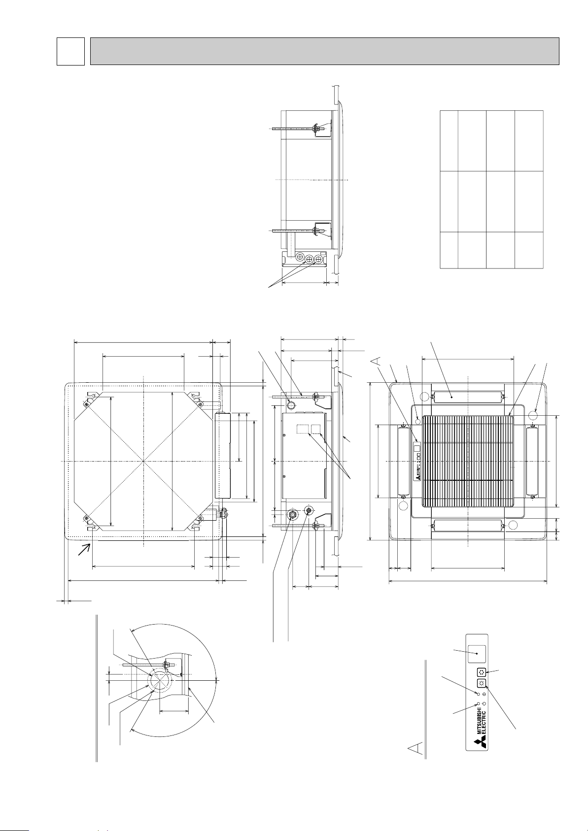
Emergency operation
switch(cooling)
Emergency operation switch(heating)
Operation lamp
(WIRELESS PANEL)
DEFROST/STAND BY lamp
Receiver
Detail drawing of fresh air intake
Ceiling surface
Cut out hole
[73.4
Burring hole
3-[2.8 hole
[100
118
25
120°
120°
377
377
650
650
Suspension
bolt lower edge
230
18248
Wiring entry
Terminal block
Ceiling surface
235
208
27
+5
0
193
20
93
38~58
66121
17 202
56
57
72
31
Ceiling hole
Suspension bolt pitch
15~37
15~37
576~620
420
570
335
199
352
335
Suspension bolt
pitch
Ceiling hole
OUTLINES AND DIMENSIONS
SLZ-A09AR.TH
SLZ-A12AR.TH
SLZ-A18AR.TH
Unit : mm
5
Page 6
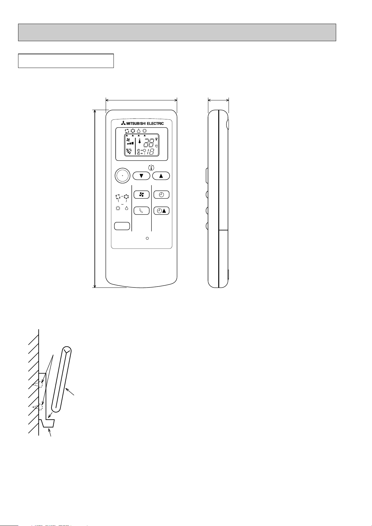
REMOTE CONTROLLER
Installation area
• Area in which the remote controller is not exposed direct sunshine.
• Area in which there is no nearby heating source.
• Area in which the remote controller is not exposed to cold (or hot) winds.
• Area in which the remote controller can be operated easily
• Area in which the remote controller is beyond the reach of children.
Installation method
1 Attach the remote controller holder to the desired location using two tapping screws.
2 Place the lower end of the controller into the holder.
A Wireless remote controller (Accessory)
B Wall
C Remote controller holder (Accessory)
D Fixing screw (Accessory)
• The signal can travel up to approximately 7 meters (in a straight line) within 45
degrees to both right and left of the center line of the receiver.
In addition, the signal may not be received if there is interference of light of fluorescent
lights or strong sunlight.
A
C
B
D
ON/OFF
RESET
TOO
WARM
TOO
COOL
MODE
AUTO COOL
DRY
HEAT
FAN
VANE
SELECT
TIME
h
57 17.5
140
Unit : mm
6
Page 7
4
GRILLE
FOR A18 (1:1 SYSTEM)
OR MULTI SYSTEM
FOR A09/12
★
★
(1:1 SYSTEM)
TO OUTDOOR
UNIT
CONNECTING
CONDENSER/EVAPORATOR
TEMPERATURE THERMISTOR
RT13
RT13
3
12VDC
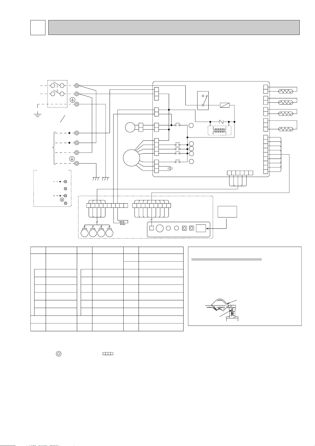
★ The 12V DC is NOT always against the ground.
Terminal 3 has 12V DC against terminal N.
However, between 3 and 2, these terminals are NOT electrically insulated by the transformer or other device.
TO OUTDOOR
UNIT
CONNECTING
2
N
TB
TERMINAL BLOCK
MV MV MV MV
CNB
BZ
LED2
LED1
SW1
SW2
RU
W.B
POWER SUPPLY
~/N
220-240V 220V
50Hz 60Hz
FAN MOTOR
CAPACITOR
C1
5
5
5
5
H2
5
BLK
DC13.1V
TRANS
X5
X5
W.R
REMOTE
CONTROLLER
TB
: Connector
: Terminal block
(For field wiring)
2.Use copper conductors only.
3.Symbols below indicate.
PIPE TEMPERATURE
THERMISTOR / LIQUID
RT12
W.R
WIRELESS REMOTE
CONTROLLER
RT11
ROOM TEMPERATURE
THERMISTOR
VANE MOTORMV
FAN MOTOR
MF
DEW PREVENTION
HEATER
H2
DRAIN SENSOR
DRAIN-UP
MACHINE
DP
DS
FUSE
FUSE(3.15A)
w WHT
3
N
2
220-240V~
12VDC
L
3
4
52C
ZNR1
DP
MF
X1
X2
X3
X4
X4
X3
X2
X1
w RED
w BLU
GRN/YLW
w WHT
N
GRN/YLW
TB
CIRCUIT BREAKER
w BLU
1.About the outdoor side electric wiring refer to the outdoor unit electlic wiring diagram for servicing.
How to remove the terminals
shown at "
w " mark.
" w " shows the terminals with a lock mechanism,
so they cannot be removed when you pull the
lead wire. Be sure to pull the wire by pushing
the locking lever (projected part) of the
terminal with a finger.
locking lever
1 Slide the sleeve.
2 Pull the wire
while pushing
the locking lever.
sleeve
NOTES:
9
BUZZER
ZNR1
VARISTOR
NAME
SYMBOLSYMBOL
NAME
SYMBOL
NAME
X1
X2-X5
RELAY(D.PUMP
/D.HEATER)
RELAY
(FAN MOTOR)
COMPRESSOR
CONTACTOR
52C
BZ
LED1
LED2
SW1
SW2
I.B
INDOOR
CONTROLLER
BOARD
W.B
WIRELESS REMOTE
CONTROLLER
BOARD
RU
LED
(RUN INDICATOR)
LED
(HOT ADJUST)
SWITCH
(HEATING ON/OFF)
SWITCH
(COOLING ON/OFF)
RECEVING UNIT
[LEGEND]
FUSE
C1
I.B
RT11
RT12
DS
(2 PHASE)
1
2
BLK
CN29
1
3
1
3
BRN
RED
ORN
YLW
BLU
VLT
GRY
PINK
SKY BLU
YLW
YLW
RED
ORN
YLW
WHT
BLU
1
745
10
89
ORN
RED
BRN
YLW
BLU
WHT
YLW
YLW
BLU
RED
WHT
RED
GRN
WHT
WHT
1
3
5
7
1
3
1
3
5
5
3
1
CNP(PUMP)
CNC
CND(POWER)
RED
CN31
CN20
CN21
(DRAIN)
(INTAKE)
(LIQUID)
CN90
(WIRELESS)
CN6V
(VANE)
(HEATER)
1
2
3
1
1
2
2
12345
1
2
3
4
5
6
7
8
9
FAN2(FAN)
FAN1(FAN)
BLU
WHT
ORN
RED
YLW
6
WHT
WHT
SKY BLU
PINK
GRY
VLT
BLU
YLW
ORN
RED
BRN
YLW
YLW
236
123456789
w
WIRING DIAGRAM
SLZ-A09AR.TH
SLZ-A12AR.TH
SLZ-A18AR.TH
7
Page 8
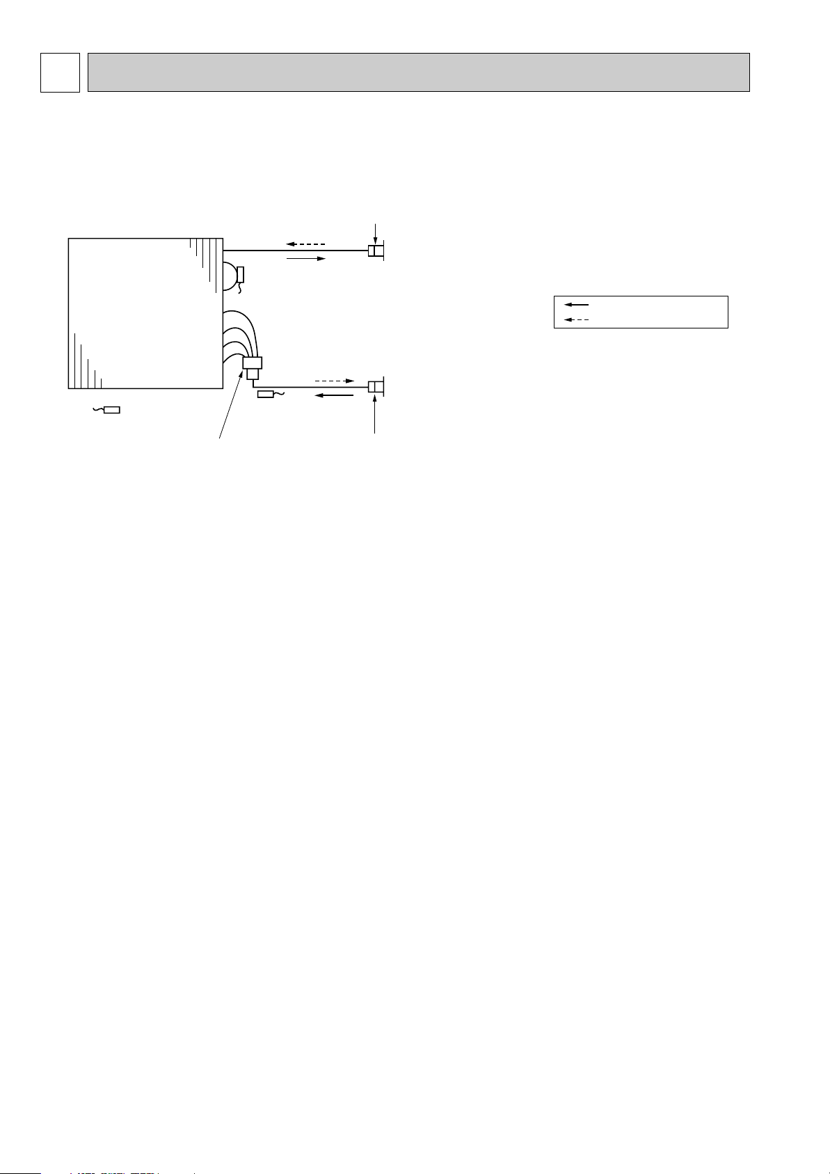
5
Pipe temperature
thermistor/liquid
(RT12)
Distributor
with strainer
#50
Condenser/evaporator
temperature thermistor
(RT13)
Room temperature
thermistor (RT11)
Refrigerant flow in cooling
Refrigerant flow in heating
Strainer
#50
Strainer
#50
Heat exchanger
Refrigerant GAS pipe connection
(Flare)
Refrigerant LIQUID pipe connection
(Flare)
REFRIGERANT SYSTEM DIAGRAM
SLZ-A09AR.TH
SLZ-A12AR.TH
SLZ-A18AR.TH
8
Page 9

6
Operation lamp
Mis-wiring1
blinking
2
blinking
Indoor-outdoor
signal error
Wiring between the indoor and
outdoor is coming off.
Difference of wiring polarity
between the indoor and outdoor.
Trouble of the outdoor inverter
P.C. board.
Check the wiring out between the indoor and
outdoor.
Check the outdoor inverter P.C. board. Refer to the
TECHNICAL & SERVICE MANUAL of outdoor unit.
Trouble of the Indoor controller
board.
Exchange the Indoor controller board.
Pipe temperature thermistor
/ Liquid.
Mis-connecting of the pipe
temperature thermistor / Liquid.
Reinsert the connector (CN21).
Trouble of the pipe temperature
thermistor / Liquid.
Trouble of the Indoor controller
board.
Exchange the Indoor controller board.
Check the resistance value of the thermistor.
Room temperature
thermistor
Mis-connecting of the room
temperature thermistor.
Reinsert the connector (CN20).
Trouble of the room temperature
thermistor.
Trouble of the Indoor controller
board.
Exchange the Indoor controller board.
Check the resistance value of the thermistor.
Condenser / evaporator
temperature thermistor
Mis-connecting of the condenser /
evaporator temperature thermistor.
Reinsert the connector (CN29).
Trouble of the condenser / evaporator
temperature thermistor.
Trouble of the Indoor controller
board.
Exchange the Indoor controller board.
Check the resistance value of the thermistor.
Drain sensor Mis-connecting of the indoor drain
sensor
Reinsert the connector (CN31).
Trouble of the indoor drain sensor
Trouble of the Indoor controller
board.
Exchange the Indoor controller board.
Check the resistance value of the thermistor.
Phenomenon
Blinking
frequency
Cause Countermeasure
TROUBLESHOOTING
6-1. Cautions on troubleshooting
(1) Before troubleshooting, check the followings:
1Check the power supply voltage.
2Check the indoor/outdoor connecting wire for mis-wiring.
(2) Take care the followings during servicing.
1 Before servicing the air conditioner, be sure to first turn off the remote controller to stop the main unit, and then turn
off the breaker.
2 When removing the indoor controller board, hold the edge of the board with care NOT to apply stress on the
components.
3 When connecting or disconnecting the connectors, hold the housing of the connector. DO NOT pull the lead wires.
6-2. Trouble display
Blinking frequency of operation lamp shows the details of trouble of the indoor and the outdoor units.
(1) Incase of being indicated irregularity on the self diagnoses.
9
To be continued on the next page.
Page 10

3
blinking
5,7,10
blinking
6
blinking
9
blinking
Freezing protection is
working.
1) Short cycle of air cycle
2) Dirty air filter
3) Damaged fan
4) Abnormal refrigerant
1) Clear obstructions from air cycle.
2) Clean the air filter
3) Check the fan
4) Check the refrigerant temperature.
Malfunction of outdoor unit Malfunction of outdoor unit Refer to the TECHNICAL & SERVICE MANUAL
of outdoor unit.
Malfunction of drain pump 1) Malfunction of drain pump
2) Damaged drain sensor
1) Check the drain pump.
2) Check the drain sensor.
(Check the drop of water is on.)
If the resistance is normal, replace the indoor
controller board.
Outdoor thermistor Mis-connecting of the outdoor
thermistor.
Reinsert the connector.
Trouble of the outdoor thermistor.
Trouble of the outdoor inverter P.C.
board.
Exchange the outdoor inverter P.C. board.
Check the resistance value of the thermistor.
Phenomenon
Blinking
frequency
Cause Countermeasure
Not working of remote
controller switch ON/OFF
Short circuit the protecting parts in the
Indoor controller board.
Trouble of the Indoor controller board. Check the Indoor controller board out.
Trouble of the remote controller.
Check the varistor (ZNR1) and fuse (FUSE) out in
the Indoor controller board.
Exchange the remote controller.
Wiring between the indoor and outdoor is
coming off.
Working the Indoor units
and not working the outdoor
units.
Check the wiring out between the indoor and
outdoor.
Difference of wiring polarity between the
indoor and outdoor.
Trouble of the outdoor inverter P.C. board.
Trouble of the contactor (52C). Exchange the contactor.
Check the outdoor inverter P.C. board.
Malfunction of outdoor unit. Refer to the TECHNICAL & SERVICE MANUAL of
outdoor unit.
Fan motor connector is coming off.
Not rotating the fan in the
indoor unit.
Trouble of the Indoor controller board.
Check the fan motor output of the Indoor
controller
board.
Check the connector out.
Trouble of the fan motor. Check the resistance value between the each tap
of fan motor.
A connector attaching the panel to the body
is not connected.
Horizontal vane doesn't work.
Check if the connector for vane motor is connected.
Connect it.
A connector attaching the panel to the body
is not connected.
Fixing of horizontal vane.
Connect it.
Phenomenon Cause Countermeasure
From the preceding page.
(2) Other case
10
Page 11

Check of indoor controller board and indoor fan motor
Operation lamp blinks once in a fixed period.
Error was found in the signal transmitted or
received between the indoor and outdoor units.
Check the condenser/evaporator
temperature thermistor.
Is the connector CN29 on the
indoor controller board connected?
No
Connection is defective.
Measure the resistance of
condenser/evaporator
temperature thermistor.
Is the connecting wire between
the indoor and outdoor units
No
connected properly?
Connection is defective.
Yes
No
Connection is defective. Connection is defective. Connection is defective.
Are there any devices emitting
noise near the power supply or
the connecting wire between the
Yes
Yes
indoor and outdoor units?
No
Remove the devices.
Turn off the power supply and turn it on again to operate the unit in
cooling or heating mode.
Operation lamp blinks once in a
No
fixed period.
Yes
Normal
Indoor controller board is defective.
Operation lamp blinks twice in a fixed period.
Check the pipe temperature
thermistor / liquid.
Is the connector CN21 on the
indoor controller board connected?
Yes
Measure the resistance
of the pipe temperature
thermistor / liquid.
Check the room temperature thermistor.
Is the connector CN20 on the
indoor controller board connected?
No
Measure the resistance of
room temperature thermistor.
Yes
Check the drain sensor thermistor.
Is the connector CN31 on the
indoor controller board connected?
No
Measure the resistance
of drain sensor.
Yes
Is the resistance 0 (short circuit) or
∞ (open circuit)?
Yes
Condenser/evaporator
temperature thermistor
is defective.
Is the resistance 0 (short circuit) or
∞ (open circuit)?
No
Yes
Pipe temperature
thermistor / liquid
is defective.
No
Room temperature
thermistor is defective.
Turn off the power supply and turn it on again to operate the unit in
cooling mode.
Operation lamp blinks twice in a
No
Normal
fixed period.
Indoor controller board is defective.
Is the resistance 0 (short circuit) or
∞ (open circuit)?
Yes
Yes
No
Drain sensor is defective.
Is the resistance 0 (short circuit) or
∞ (open circuit)?
Yes
No
To be continued on the next page.
11
Page 12

Yes No
No
Yes
No
Yes
No
The switch of remote controller does not work.
Connection is defective.
Indoor controller board is defective.
Is the connecting
wire between the
indoor unit and
the decoration
panel connected
Is the varistor on
the indoor controller
board burnt?
Yes
Replace the varistor.
No
Is the fuse on the
indoor controller
board melted?
Yes
Yes
Replace the fuse.
Check the followings.
•The display on the remote controller does
not appear on the screen.
•The display on the remote controller is dim.
•The indoor unit does not respond to the
remote control signal when the remote
controller is not operated near the signal
receiving section on the unit.
Replace the batteries.
No
Replace the
remote controller.
Does the display appear on the
screen?
Does the indoor unit receive the
remote control signal when the
remote controller is not operated
near the signal receiving section
on the unit?
Indoor fan motor does not rotate.
Measure the resistance of connectors FAN1
and 2 on the indoor controller board.
Connection is defective.
Turn off the power supply and check the connectors
FAN1 and 2 on the indoor controller board visually.
Indoor fan motor is defective.
Are the connectors FAN1 and 2
connected?
Indoor controller board is defective.
Is the resistance 0 (short circuit) or
∞ (open circuit)?
From the preceding page.
12
Page 13

6-3. Test point of indoor controller board
Indoor controller board
Pipe temperature thermistor/liquid (RT12)
Condenser/evaporator
temperature thermistor
(RT13)
Room temperature thermistor (RT11)
Drain sensor (DS)
Power supply
input 220-240V AC
Fuse 250V AC 3.15A
• Room temperature thermistor (RT11)
• Pipe temperature thermistor/liquid (RT12)
• Condenser/evaporator temperature
thermistor (RT13)
< Thermistor for lower temperature >
50
40
30
20
Resistance (K")
10
0
-20 -10 0 10 20 30 40 50
Temperature (:)
13
Page 14

6-4. Trouble criterion of main parts
BLK RED ORNYLW
BLU
BRN
WHT
P
Room temperature
thermistor
(RT11)
Condenser/evaporator
temperature thermistor
(RT13)
Measure the resistance with a tester.
(Part temperature 10°C ~ 30°C)
Measure the resistance between the terminals with a tester.
(Coil wiring temperature 10°C ~ 30°C)
Pipe temperature
thermistor/liquid
(RT12)
Indoor fan motor
(MF)
Check method and criterion
Part name
Normal
A09AR
Normal
WHT-BLK
BLK-BLU
BLU-YLW
YLW-BRN
BRN-RED
386~428
52~58
29~33
28~32
157~174
A12AR
309~399
107~115
47~51
44~48
299~323
A18AR
305~329
85~92
50~54
43~47
289~313
4.3kΩ~9.6kΩ
Abnormal
Abnormal
Opened or
short-circuited
Opened or short-circuited
Measure the resistance between the terminals using a tester.
(Surrounding temperature 20:~30:)
Measure the resistance between the terminals using a tester.
(Surrounding temperature 20:~30:)
Measure the resistance between the terminals using a tester.
(Surrounding temperature 10:~30:)
Vane motor (MV)
Drain pump (DP)
Drain sensor (DS)
(Refer to the thermistor)
1
2
Yellow
Yellow
1
2
3
Abnormal
Open or short
Normal
0.6k"~6.0k"
NormalConnector Abnormal
300" Open or short
Normal Abnormal
290" Open or short
Orange
Red
White
P : Thermal fuse 145 ± 2˚C
Red — Yellow
Red — Blue
Red — Orange
Red — White
Blue
Yellow
35
1
2
4
M
SLZ-A09AR.TH
SLZ-A12AR.TH
SLZ-A18AR.TH
14
Page 15

<Thermistor Characteristic graph>
-200 20406080
< Thermistor for drain sensor >
Temperature (:)
0
1
2
3
4
5
6
7
8
9
10
Resistance (K")
Thermistor for
lower temperature
•Room temperature thermistor (RT11)
•Pipe temperature thermistor/liquid (RT12)
•Condenser/evaporator temperature
thermistor (RT13)
Thermistor R0=15k' ±3%
Fixed number of B=3480K ± 2%
Rt=15exp { 3480( ) }
1
273+t
1
273
0: 15k'
10: 9.6k'
20: 6.3k'
25: 5.2k'
30: 4.3k'
40: 3.0k'
Thermistor for
drain sensor
< Thermistor for lower temperature >
50
40
30
20
Resistance (K")
10
0
-20 -10 0 10 20 30 40 50
Temperature (:)
Thermistor R0=6.0k' ±5%
Fixed number of B=3390K ± 2%
Rt=6exp { 3390( ) }
1
273+t
0: 6.0k'
10: 3.9k'
20: 2.6k'
25: 2.2k'
30: 1.8k'
40: 1.3k'
1
273
15
Page 16

7 4-WAY AIR FLOW SYSTEM
Detail drawing of fresh air intake
Ceiling surface
Refrigerant pipe
Drain pipe
Electrical Box
Cut out hole
[73.4
Burring hole
3-[2.8 hole
[100
118
25
120°
120°
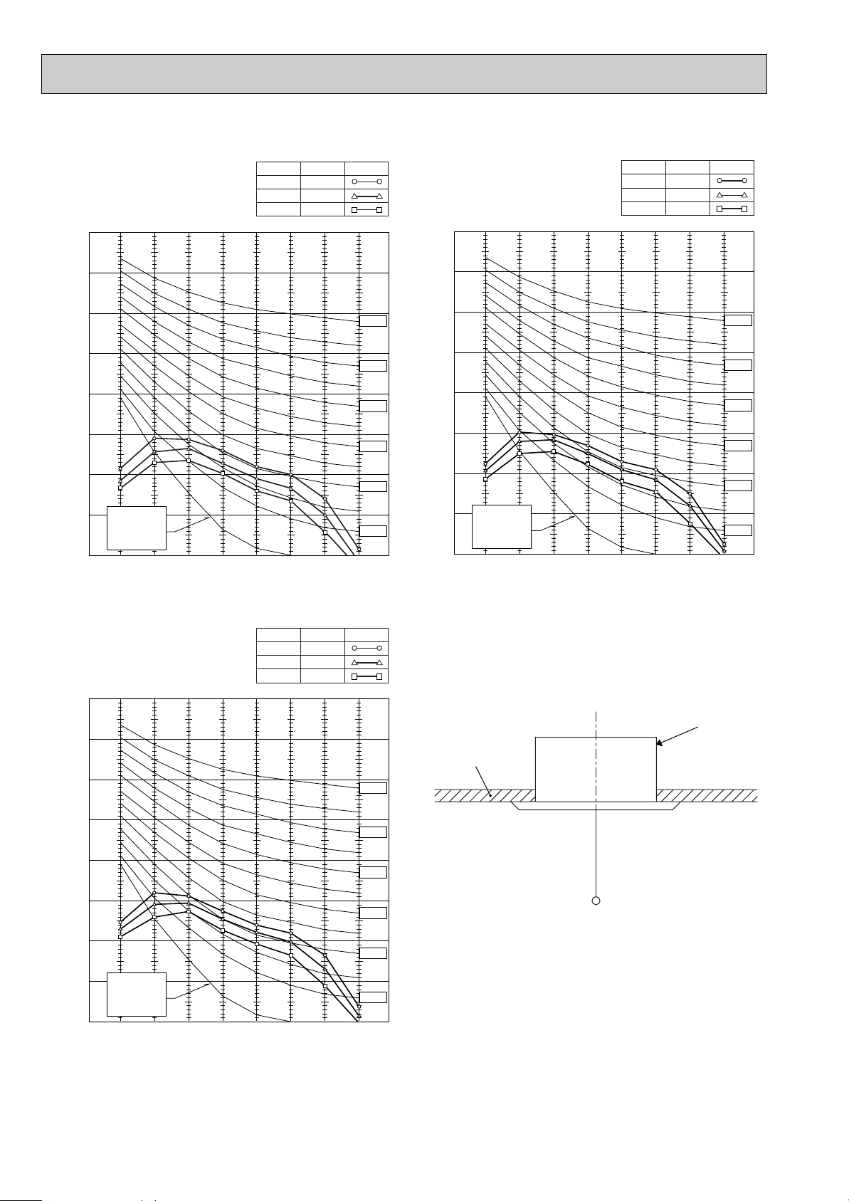
Fresh air intake
Static pressure : P [Pa]
Air flow : Q [m
3
/min]
50
-50
-100
-150
-200
-250
-300
0
0.5 1.0 1.5 2.0 2.5 3.0 3.5
Q
0
B
A
C
1
Curve in the
left praphs.
Duct characteristics
at site
Q
A
EC
2
Q
Qa
AD
3
CN51
Multiple remote
controller adapter
PAC-SA88HA-E
Indoor controller board
Distance between indoor
controller board and relay
must be within 10m.
Be sure to secure insulation
material by tape and such
5
Green
Yellow
Orange
Connector (5P)
Package side
Multiplr remote
controller adapter
PAC-SA88HA-E
Be sure to secure insulation
material by tape and such
Installation at site
CN51
on
indoor unit
board
Red
Brown
1
MB
~
CNPCNCCND FAN2
C1
FAN1
52C
C412
CN51
RC00J590B
7-1. Fresh air intake (Location for installation)
At the time of installation, use the duct holes (cut out) located at the positions shown in following diagram, as and when required.
7-2. Fresh air intake amount & static pressure characteristics
SLZ-A09AR.TH
SLZ-A12AR.TH
SLZ-A18AR.TH
Taking air into the unit
How to read curves
NOTE: Fresh air intake amount should be 20% or less of
whole air amount to prevent dew dripping.
7-3. Interlocking operation method with duct fan (Booster fan)
●Whenever the indoor unit is operating, the duct fun
operates.
(1)Connect the optional multiple remote controller
adapter(PAC-SA88HA-E)to the connector CN51 on the
indoor controller board.
(2)Drive the relay after connecting the 12V DC relay
Use a relay under 1W.
MB: Electromagnetic switch power relay for duct fan.
X: Auxiliary relay (12V DC LY-1F)
between the Yellow and Orange connector lines.
16
Q…Planned amount of fresh air intake
A…Static pressure loss of fresh air
intake duct system with air flow
amount Q
B…Forced static pressure at air condi-
tioner inlet with air flow amount Q
C…Static pressure of booster fan with
air flow amount Q
D…Static pressure loss increase
amount of fresh air intake dust system for air flow amount Q <Pa>
E…Static pressure of indoor unit with air
flow amount Q
Qa…Estimated amount of fresh air
intake with out D <m3/min>
<m
3
/min>
<Pa>
<Pa>
<Pa>
<Pa>
Page 17

7-4. Fixing of horizontal vane
Standard of
horizontal position
Dimension A (mm)
21 25 28 30
Level 30°
(Min.)
Downward 45° Downward 55°
Downward 70°
(Max.)
w Dimension between 21 mm and 30 mm can be arbitrarily set.
Caution
Do not set the dimension out of the range.
Erroneous setting could cause dew drips, smudge on ceiling or malfunction of unit.
<Set range>
.
Horizontal vane of each air outlet can be fixed according to the environment, which is installed.
Setting procedure
1) Turn off a main power supply (Turn off a breaker).
2) Disconnect the vane motor connector of the direction of the arrow with pressing the unlocking button as shown in figure
below.
Electricity insulate the disconnected connector with the vinyl tape.
Vane motor
Vane motor
Connector
Horizontal vane
3) Set a vertical vane of the air outlet, which tries to fixed by the hand slowly within the range in the table below.
Measured standard
position of the grille
Horizontal vane
Unlocking button
17
Page 18

8 DISASSEMBLY PROCEDURE
SLZ-A09AR.TH SLZ-A12AR.TH SLZ-A18AR.TH
OPERATING PROCEDURE PHOTOS&ILLUSTRATIONS
1. Removing the air intake grille
(1) Slide the knob of air intake grille to the direction of the
arrow 1 to open the air intake grille.
(2) Remove the hook for secure belt on air inlet grille from the
panel.
(3) Slide the shaft in the hinge to the direction of the arrow 2
and remove the air intake grille.
2. Removing the fan guard
(1) Open the air intake grille.
(2) Remove the 3 screws of fan guard.
Be careful on removing heavy parts.
Figure 1
Air intake grille
Grille
Air intake grille knob
Photo 1
Fan guard
Screws
3. Removing the panel
(1) Remove the air intake grille. (Refer to 1)
Corner panel (See figure 2)
(1) Remove the screw of the corner.
(2) Slide the corner panel to the direction of the arrow 3, and
remove the corner panel.
Panel (See photo 2)
(1) Disconnect the connector that connects with the unit.
(2) Remove the 2 screws from the panel and loose another 2
screws, which fixed to the oval hole, have different diameter.
(3) Rotate the panel a little to remove the screws.(Slide the
panel so that the screw comes to a large diameter of the
oval hole, which has two different diameters.)
4. Removing the electrical parts
(1) Remove the 2 screws and the control box cover.
<Electrical parts in the control box>
• Indoor controller board (I.B)
• Compressor contactor (52C)
• Fuse (FUSE)
• Varistor (ZNR1)
• Terminal block (TB)
Figure 2
Screw
Corner
panel
Photo 2
Connectors
Screws
Photo 3
Indoor controller board
(I.B)
Corner
panel
Varistor
(ZNR1)
Air intake grille
Panel
Screws
Panel
Indoor
controller box
Compressor contactor
(52C)
18
Fuse
(FUSE)
Terminal blocks
(TB)
Page 19

OPERATING PROCEDURE
PHOTOS&ILLUSTRATIONS
5. Remove the room temperature thermistor (RT11)
(1) Remove the panel. (Refer to 3)
(2) Pull out the room temperature thermistor from the drain
pan.
(3) Remove the 2 screws fixed to the control box cover, and
remove the control box cover.
(4) Remove the connector (CN20) from the indoor controller
board, and disconnect the room temperature thermistor.
6. Remove the drain pan
(1) Remove the panel. (Refer to 3)
(2) Remove the room temperature thermistor and the 2 lead
wires held with fastener; wireless controller board relay
connector (9P red) and panel relay connector (10P white).
(3) Remove the 4 screws fixed to the drain pan, and remove
the drain pan.
(4) Remove the fan guard. (Refer to 2)
7. Removing the pipe temperature thermistor/liquid (RT12)
and condenser/evaporator temperature thermistor (RT13)
(1) Remove the panel. (Refer to 3)
(2) Remove the drain pan. (Refer to 6)
(3) Disconnect the indoor coil thermistor from the holder.
(4) Remove the 3 screws fixed to the piping cover, and
remove the piping cover. (See photo 9)
(5) Remove the 2 screws fixed to the control box cover, and
remove the control box cover.
Photo 4
Screw
Room
temperature
thermistor
(RT11)
Screw
Photo 5
Control box
Fan guard
Control box
Connectors
Drain plug
Screw
Drain pan
Screw
Pipe temperature thermistor/liquid (RT12)
(6) Remove the connector (CN21) from the indoor controller
board, and disconnect the pipe temperature thermistor/liquid.
Condenser/evaporator temperature thermistor (RT13)
(6) Remove the connector (CN29) from the indoor controller
board, and disconnect the condenser/evaporator temperature
thermistor.
8. Remove the fan motor (MF)
(1) Remove the panel. (Refer to 3)
(2) Remove the drain pan. (Refer to 6)
(3) Remove the nut and the washer from the turbo fan, and
remove the turbo fan.
(4) Remove the 2 screws fixed to the control box cover, and
remove the control box cover.
(5) Disconnect the connectors of the (fan 1) and the (fan 2)
from the indoor controller board.
(6) Remove the 3 screws fixed to the piping cover, and
remove the piping cover. (See photo 9)
(7) Remove the 6 screws fixed to the flat plate, and remove
the flat plate.
(8) Disconnect the lead wires to the direction of the fan motor,
and remove the 3 nuts of the fan motor.
Pipe temperature
thermistor/liquid
(RT12)
Photo 6
Screws
Lead
wires
Screw
Flat plate
Condenser/evaporator
temperature thermistor
(RT13)
Screw
Nut
Nut
Fan motor
(MF)
Nut
Screws
19
Page 20

OPERATING PROCEDURE PHOTOS&ILLUSTRATIONS
9. Removing the drain pump (DP) and drain sensor (DS)
(1) Remove the panel. (Refer to 3 )
(2) Remove the drain pan. (Refer to 6)
(3) Remove the 2 screws fixed to the control box cover, and
remove the control box cover.
(4) Remove the connectors of the (CNP) and the (CN31)
from the indoor controller board.
(5) Remove the 1 screw fixed to the cover, and remove the
cover.
(6) Disconnect the lead wires to the direction of the drain
pump.(See photo 7)
(7) Remove the 3 screws of the drain pump.
(8) Cut the drain hose band, pull out the drain hose from the
drain pump.
(9) Pull out the drain pump.
(10) Remove the drain sensor and the holder.
10. Removing the heat exchanger
(1) Remove the panel. (Refer to 3 )
(2) Remove the drain pan. (Refer to 6)
(3) Remove the nut and the washer from the turbo fan, and
remove the turbo fan.
(4) Remove the 2 screws fixed to the control box cover, and
remove the control box cover.
(5) Disconnect the connectors of the (fan 1) and the (fan 2)
from the indoor controller board.
(6) Remove the 3 screws fixed to the piping cover, and
remove the piping cover. (See photo 9)
(7) Remove the pipe temperature thermistor/liquid and
condenser/evaporator temperature thermistor. (Refer to 7)
(8) Disconnect the lead wires to the direction of the fan motor.
(9) Remove the 1 coil support screw, the 2 inside coil screws
(See photo 10), and the 4 outside coil screws (See photo 9)
from the heat exchanger, and remove the heat exchanger.
Photo 7
Control
box
Photo 8
Drain
hose
Screw
Photo 9
Coil
screws
Screws of
piping cover
Piping cover
Screw
Drain sensor (DS) Drain pump (DP)
Fixing band
Cover
Lead wires
Lead wires
Screws
Control box
Coil
screws
Control box
20
Photo 10
Coil screws
Coil
support
Coil
support
Screw
Heat exchanger
Page 21

PARTS LIST9
No.
Parts No.
Specification
Remarks
(Drawing No.)
Unit
Amount
Wiring
Diagram
Symbol
Recom-
mended
Q'ty
Price
1
2
3
4
5
6
7
8
9
10
1
1
4
4
1
1
4
8
4
4
W.B
MV
E07 103 003
E07 103 317
E07 103 037
E07 103 975
E07 103 100
E07 103 010
E07 103 303
E07 103 044
E07 103 031
E07 103 032
AIR OUTLET GRILLE
WIRELSS REMOTE CONTROL BOARD
AUTO VANE
CORNER PANEL
AIR FILTER
INTAKE GRILLE
VANE MOTOR
VANE BUSH
GEAR (V)
GEAR (M)
Parts name
SLP-2AL
Q'ty/set
PANEL PARTS
SLP-2AL
1
10
9
8
3
2
7
4
5
6
21
Page 22

FUNCTIONAL PARTS
ON/OFF
RESET
TOO
WARM
TOO
COOL
MODE
AUTO COOL
DRY
HEAT
FAN
VANE
SELECT
TIME
h
SLZ-A09AR.TH
SLZ-A12AR.TH
SLZ-A18AR.TH
22
23
1
3
2
3
22
21
4
20
5
19
18
17
6
16
15
7
8
9
10
24
11
25
12
13
14
22
Page 23

No.
1
E07 104 290
2
E07 104 124
3
E07 104 808
4
E07 105 124
E07 140 620
5
E07 141 620
E07 142 620
6
E07 104 105
E07 140 300
7
E07 105 300
E07 106 300
8
E07 104 816
9
E07 104 502
10
E07 104 097
11
E07 104 700
12
E07 104 308
13
E07 104 520
14
E07 104 524
15
E07 104 648
16
E07 140 309
17
E07 104 307
18
E07 104 702
19
E07 104 266
20
E07 104 241
21
E07 104 355
22
E07 104 809
23
E07 104 006
24
E07 140 426
25
E02 527 083
Parts nameParts No. Specification
BASE
DRUM-1
LEG-1
DRUM-2
I
NDOOR HEAT EXCHANGER
INDOOR HEAT EXCHANGER
INDOOR HEAT EXCHANGER
MOTOR MOUNT
INDOOR FAN MOTOR
INDOOR FAN MOTOR
INDOOR FAN MOTOR
FLAT PLATE
TURBO FAN
SPL WASHER
DRAIN PAN
ROOM TEMPERATURE THERMISTOR
FAN GUARD
DRAIN PLUG
COIL SUPPORT
CONDENSER / EVAPORATOR
TEMPERATURE THERMISTOR
PIPE TEMPERATURE THERMISTOR / LIQUID
DRAIN HOSE
DRAIN SENSOR
SENSOR HOLDER
DRAIN PUMP
LEG-2
COVER (DRUM)
WIRELESS REMOTE CONTROLLER
REMOTE CONTROLLER HOLDER
PK6V15-LA
PK6V20-LE
PK6V20-LF
Q'ty/set
SLZ-
A12A09 A18
AR.TH
1
1
2
1
1
3
1
1
1
1
1
1
1
1
1
1
1
1
1
1
1
2
1
1
1
Unit
Price
Amount
Wiring
Symbol
MF
MF
MF
RT11
RT13
RT12
DS
DP
W.R
Recom-
mended
Q'ty
Remarks
(Drawing No.)
1
1
1
1
2
2
1
1
1
1
3PCS/SET
3
3
1
1
1
1
1
1
1
1
1
1
1
1
1
1
1
1
1
1
1
1
1
1
1
1
1
1
1
1
1
1
2
2
1
1
1
1
1
1
Diagram
23
Page 24

ELECTRICAL PARTS
No.
Parts No.
Parts name
Specification
Remarks
(Drawing No.)
Unit
Amount
Wiring
Diagram
Symbol
Recom-
mended
Q'ty
Price
1
2
3
4
5
6
E07 140 340
E02 127 382
E02 661 385
E02 367 377
E02 257 375
E07 140 447
E07 141 447
E07 142 447
COMPRESSOR CONTACTOR
FUSE
VARISTOR
TERMINAL BLOCK
TERMINAL BLOCK
INDOOR CONTROLLER BOARD
INDOOR CONTROLLER BOARD
INDOOR CONTROLLER BOARD
52C
FUSE
ZNR1
TB
TB
I.B
I.B
I.B
250V 3.15A
1
1
1
1
1
1
1
1
1
1
1
1
1
1
1
1
1
1
Q'ty/set
SLZ-
A12A09 A18
AR.TH
3P
4P
SLZ-A09AR.TH
SLZ-A12AR.TH
SLZ-A18AR.TH
6
N
2
220-240V~
3
N
220-240V
L
TO OUTDOOR
UNIT
POWER
SUPPLY
5
1 324
CCopyright 2004 MITSUBISHI ELECTRIC ENGINEERING CO., LTD.
Distributed in Mar. 2004 No.OC302 PDF 8
Made in Japan.
HEAD OFFICE : MITSUBISHI DENKI BLDG., 2-2-3, MARUNOUCHI, CHIYODA-KU, TOKYO 100-8310, JAPAN
New publication, effective Mar. 2004.
Specifications subject to change without notice.
 Loading...