

Page 1
SHOGUN
OWNER’S MANUAL
SHOGUN - EN-UK - OVWX17E1
SHOGUN - EN-UK - OVWX17E1
Page 2
Foreword
E09200106777
Thank you for selecting a SHOGUN as your new vehicle.
This owner’s manual will add to your understanding and full enjoyment of
the many fine features of this vehicle.
It contains information prepared to acquaint you with the proper way to operate and maintain your vehicle for the utmost in driving pleasure.
MITSUBISHI MOTORS Europe B.V. reserves the right to make changes in
design and specifications and/or to make additions to or improvements in
this product without obligation to install them on products previously manufactured.
It is an absolute requirement for the driver to strictly observe all laws and
regulations concerning vehicles.
This owner’s manual has been written in compliance with such laws and regulations, but some of the contents may become contradictory with later
amendment of the laws and regulations.
Please leave this owner’s manual in this vehicle at time of resale. The next
owner will appreciate having access to the information contained in this
owner’s manual.
Repairs to your vehicle:
Vehicles in the warranty period:
All warranty repairs must be carried out by a MITSUBISHI MOTORS Authorized Service Point.
Vehicles outside the warranty period:
Where the vehicle is repaired is at the discretion of the owner.
Throughout this owner’s manual the words WARNING and CAUTION
appear.
These serve as reminders to be especially careful. Failure to follow instructions could result in personal injury or damage to your vehicle.
WARNING
indicates a strong possibility of severe personal injury or death if instructions are not followed.
CAUTION
means hazards or unsafe practices that could cause minor personal injury or damage to your vehicle.
You will see another important symbol:
NOTE: gives helpful information.
*: indicates optional equipment.
It may differ according to the sales classification; refer
to the sales catalogue.
Abbreviations used in this owner’s manual:
LHD: Left-Hand Drive
RHD: Right-Hand Drive
M/T: Manual transmission
A/T: Automatic Transmission
The symbol used on the vehicles:
: See owner’s manual
Information for station service
E09300104338
Fuel
Capacity
3-door models 69 litres
5-door models 88 litres
Fuel requirements
Petrol-powered vehicles
Unleaded petrol octane number (EN228)
90 RON or higher
If the “PREMIUM FUEL ONLY” label is attached to the fuel tank filler door,
fill it up with premium fuel.
Diesel-powered vehicles
Cetane number (EN590)
51 or higher
Refer to “General information” section for the fuel selection.
Engine oil Refer to the “Maintenance”section for the selection of engine oil.
Tyre inflation pressure Refer to the “Maintenance” section for the tyre inflation pressure.
© 2016 Mitsubishi Motors Corporation
17
OVWX17E1
BLO-16-000629
Page 3

Table of contents
Overview
General information
Locking and unlocking
Seat and seat belts
Instruments and controls
Starting and driving
For pleasant driving
For emergencies
Vehicle care
Maintenance
Specifications
Alphabetical index
Declaration of Conformity
1
2
3
4
5
6
7
8
9
10
11
12
13
OVWX17E1
Page 4
LHD
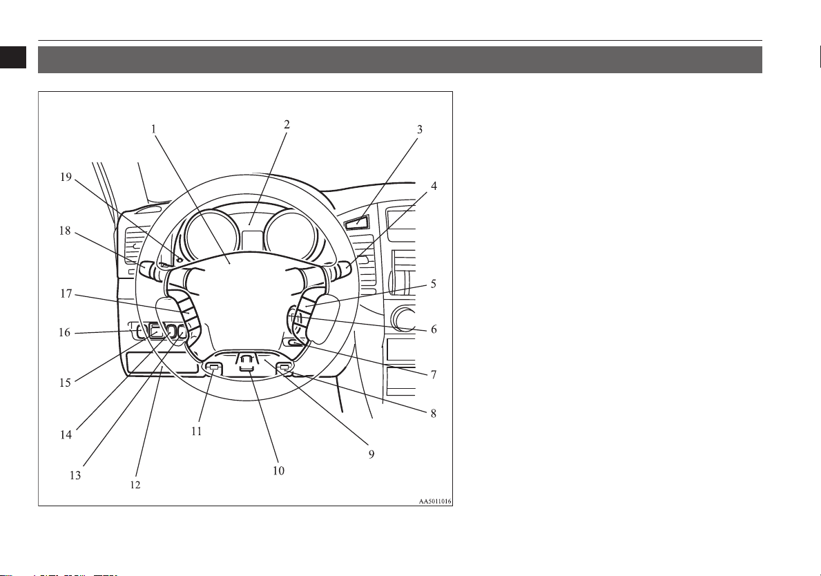
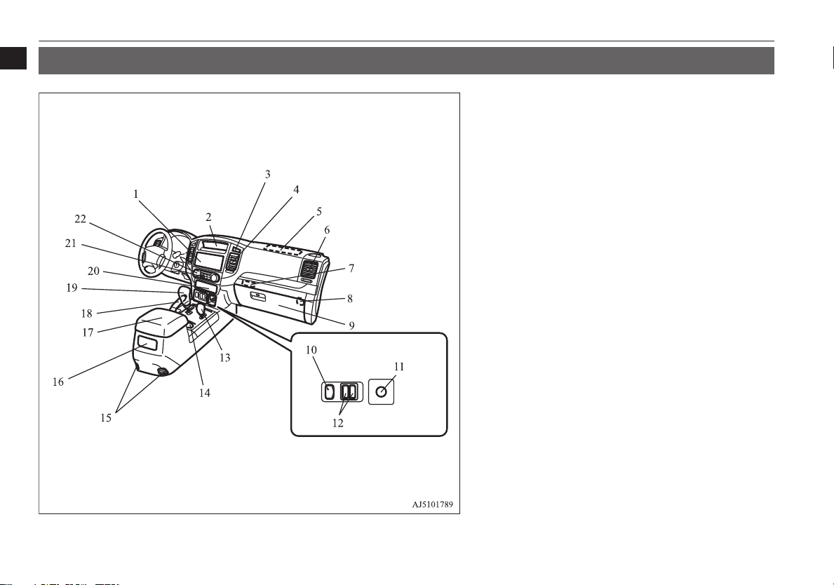
Instruments and Controls (Driver’s area)
1
Instruments and Controls (Driver’s area)
E00100108432
1. Supplemental restraint system - airbag (for driver’s seat) p. 4-36
Horn switch p. 5-50
2. Instruments p. 5-02
3. Hazard warning flasher switch p. 5-42
4. Windscreen wiper and washer switch p. 5-44
Rear window wiper and washer switch p. 5-48
5. Cruise control switch* p. 6-44
6. Ignition switch p. 6-10
7. Active Stability Control switch p. 6-40
8. Fuel tank filler door release lever p. 2-03
9.
Steering control switch (for Bluetooth® 2.0 interface)* p. 7-51
10. Steering wheel height adjustment p. 6-06
11. Bonnet release lever p. 10-03
12. Fuse block lid p. 10-18
13. Sonar cancel switch* p. 6-52
14. Headlamp levelling switch* p. 5-40
Automatic high-beam switch* p. 5-36
15. Electric remote-controlled outside rear-view mirror switch
p. 6-08
16. Front fog lamp switch* p. 5-43
Rear fog lamp switch p. 5-43
17. Audio switch* p. 7-24
18. Combination headlamps and dipper switch p. 5-34
Turn-signal lever p. 5-42
Headlamp washer switch* p. 5-48
19. Daytime dipper button (meter illumination control) p. 5-07
1-02
Overview
OVWX17E1
Page 5
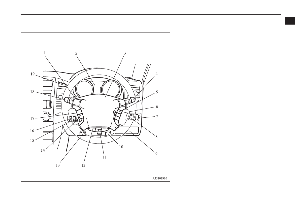
RHD
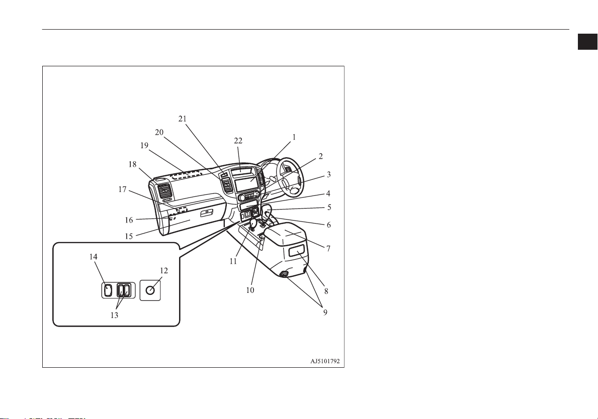
Instruments and Controls (Driver’s area)
1. Daytime dipper button (meter illumination control) p. 5-07
2. Instruments p. 5-02
3. Supplemental restraint system - airbag (for driver’s seat) p. 4-36
Horn switch p. 5-50
4. Windscreen wiper and washer switch p. 5-44
Rear window wiper and washer switch p. 5-48
5. Cruise control switch* p. 6-44
6. Ignition switch p. 6-10
7. Front fog lamp switch* p. 5-43
Rear fog lamp switch p. 5-43
8. Electric remote-controlled outside rear-view mirror switch
p. 6-08
9. Fuse block lid p. 10-18
10. Bonnet release lever p. 10-03
11. Steering wheel height adjustment p. 6-06
12.
Steering control switch (for Bluetooth® 2.0 interface)* p. 7-51
13. Fuel tank filler door release lever p. 2-03
14. Headlamp levelling switch* p. 5-40
Automatic high-beam switch* p. 5-36
15. Sonar cancel switch* p. 6-52
16. Active stability control switch p. 6-40
17. Audio switch* p. 7-24
18. Combination headlamps and dipper switch p. 5-34
Turn-signal lever p. 5-42
Headlamp washer switch* p. 5-48
19. Hazard warning flasher switch p. 5-42
1
OVWX17E1
Overview
1-03
Page 6
LHD
Instruments and Controls (Instrument panel)
1
Instruments and Controls (Instrument panel)
E00100108982
1. Audio* p. 7-12
DISPLAY AUDIO*/Smartphone Link Display Audio*/
MITSUBISHI Multi-Communication System (MMCS)*
[Refer to the separate owner’s manual]
2. Centre information display p. 5-12
3. Front passenger’s airbag OFF indication lamp p. 4-40
4. Centre ventilators p. 7-02
5. Supplemental restraint system - airbag (for front passenger’s seat)
p. 4-36
6. Side ventilators p. 7-02
7. Auxiliary Video connector (RCA)* p. 7-39
USB port* p. 7-71
HDMI port* p. 7-74
8. Front passenger’s airbag ON-OFF switch p. 4-39
9. Glove box p. 7-82
10. Rear differential lock switch* p. 6-26
11. Cigarette lighter* p. 7-76
Accessory socket* p. 7-77
12. Heated seat switch* p. 4-09
13. Transfer shift lever p. 6-21
14. Cup holder (for front seats) p. 7-85
15. Floor ventilators* p. 7-02
16. Rear air conditioning* p. 7-09
17. Armrest (for front seats) p. 4-08
Centre console box p. 7-83
Accessory socket p. 7-77
18. Parking brake lever p. 6-04
19. Selector lever p. 6-15
20. Centre accessory box* p. 7-83
21. Rear window demister switch p. 5-50
22. Front automatic air conditioning p. 7-03
1-04
Overview
OVWX17E1
Page 7
RHD
Instruments and Controls (Instrument panel)
1
1. Audio* p. 7-12
DISPLAY AUDIO*/Smartphone Link Display Audio*/
MITSUBISHI Multi-Communication System (MMCS)*
[Refer to the separate owner’s manual]
2. Front automatic air conditioning p. 7-03
3. Rear window demister switch p. 5-50
4. Centre accessory box* p. 7-83
5. Selector lever p. 6-15
6. Parking brake lever p. 6-04
7. Armrest (for front seats) p. 4-08
Centre console box p. 7-83
Accessory socket p. 7-77
8. Rear air conditioning* p. 7-09
9. Floor ventilators* p. 7-02
10. Cup holder (for front seats) p. 7-85
11. Transfer shift lever p. 6-21
12. Cigarette lighter* p. 7-76
Accessory socket* p. 7-77
13. Heated seat switch* p. 4-09
14. Rear differential lock switch* p. 6-26
15. Glove box p. 7-82
16. Front passenger’s airbag ON-OFF switch p. 4-39
17. Auxiliary Video connector (RCA)* p. 7-39
USB port* p. 7-71
HDMI port* p. 7-74
18. Side ventilators p. 7-02
19. Supplemental restraint system - airbag (for front passenger’s seat)
p. 4-36
20. Centre ventilators p. 7-02
21. Front passenger’s airbag OFF indication lamp p. 4-40
22. Centre information display p. 5-12
OVWX17E1
Overview
1-05
Page 8
LHD
Type 1 Type 2
1
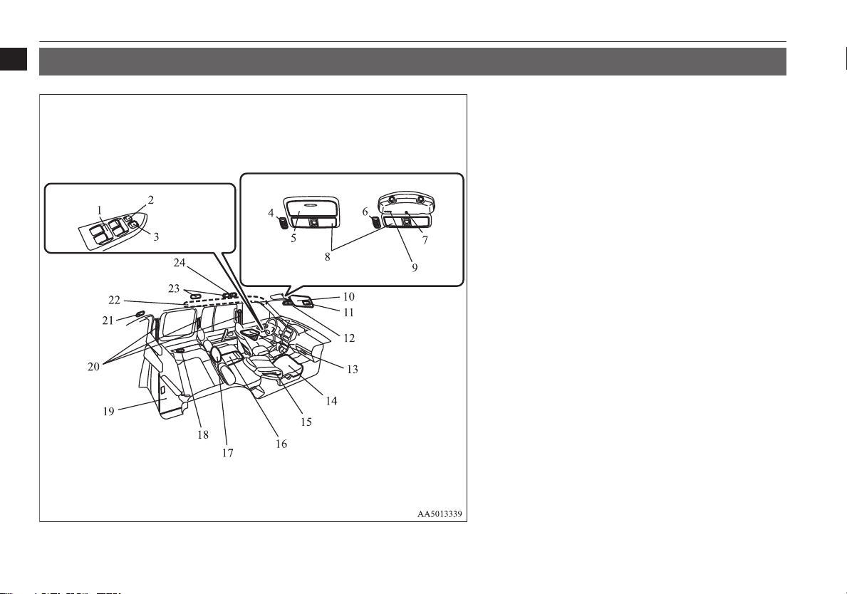
Interior
Interior
E00100206325
1. Electric window control p. 3-16
2. Electric window lock switch p. 3-17
3. Central door lock switch p. 3-07
4. Sunroof switch* p. 3-19
5. Sunglasses holder* p. 7-84
6. Sunroof switch* p. 3-19
7. Ceiling lamp p. 7-78
8. Room & map lamp p. 7-79, 10-25, 10-30
Interior lamp switch p. 7-78
9. Microphone (for Hands-free & voice recognition)* p. 7-51
10. Sun visors p. 7-74
11. Vanity mirror p. 7-74
12. Inside rear-view mirror p. 6-07
13. Video Entertainment System*
Refer to the separate “Video Entertainment System owner’s manual”
14. Seat p. 4-02
15. Supplemental restraint system - side airbag (for front seats)*
p. 4-36
16. Armrest (for rear/second seat) p. 4-10
Cup holder (for rear/second seat) p. 7-85
17. Head restraints p. 4-12
18. Cup holder (for third seat)* p. 7-86
19. Luggage floor box p. 7-84
20. Seat belts p. 4-21
Adjustable seat belt anchor (front seats) p. 4-23
21. Luggage compartment lamp p. 7-80, 10-25, 10-31
22. Supplemental restraint system - curtain airbag* p. 4-36
23. Roof ventilators (5-door models)* p. 7-02
24. Rear personal lamps p. 7-79, 10-25, 10-30
1-06
Overview
OVWX17E1
Page 9
RHD
Type 1 Type 2
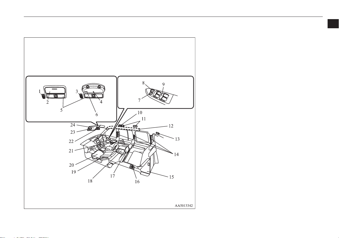
Interior
1
1. Sunroof switch* p. 3-19
2. Sunglasses holder* p. 7-84
3. Room & map lamp p. 7-79, 10-25, 10-30
Interior lamp switch p. 7-78
4. Sunroof switch* p. 3-19
5. Microphone (for Hands-free & voice recognition)* p. 7-51
6. Ceiling lamp p. 7-78
7. Electric window lock switch p. 3-17
8. Central door lock switch p. 3-07
9. Electric window control p. 3-16
10. Rear personal lamps p. 7-79, 10-25, 10-30
11. Roof ventilators (5-door models)* p. 7-02
12. Supplemental restraint system - curtain airbag* p. 4-36
13. Luggage compartment lamp p. 7-80, 10-25, 10-31
14. Seat belts p. 4-21
Adjustable seat belt anchor (front seats) p. 4-23
15. Luggage floor box p. 7-84
16. Cup holder (for third seat)* p. 7-86
17. Head restraints p. 4-12
18. Armrest (for rear/second seat) p. 4-10
Cup holder (for rear/second seat) p. 7-85
19. Supplemental restraint system - side airbag (for front seats)*
p. 4-36
20. Seat p. 4-02
21. Video Entertainment System*
Refer to the separate “Video Entertainment System owner’s manual”
22. Inside rear-view mirror p. 6-07
23. Vanity mirror p. 7-74
24. Sun visors p. 7-74
OVWX17E1
Overview
1-07
Page 10
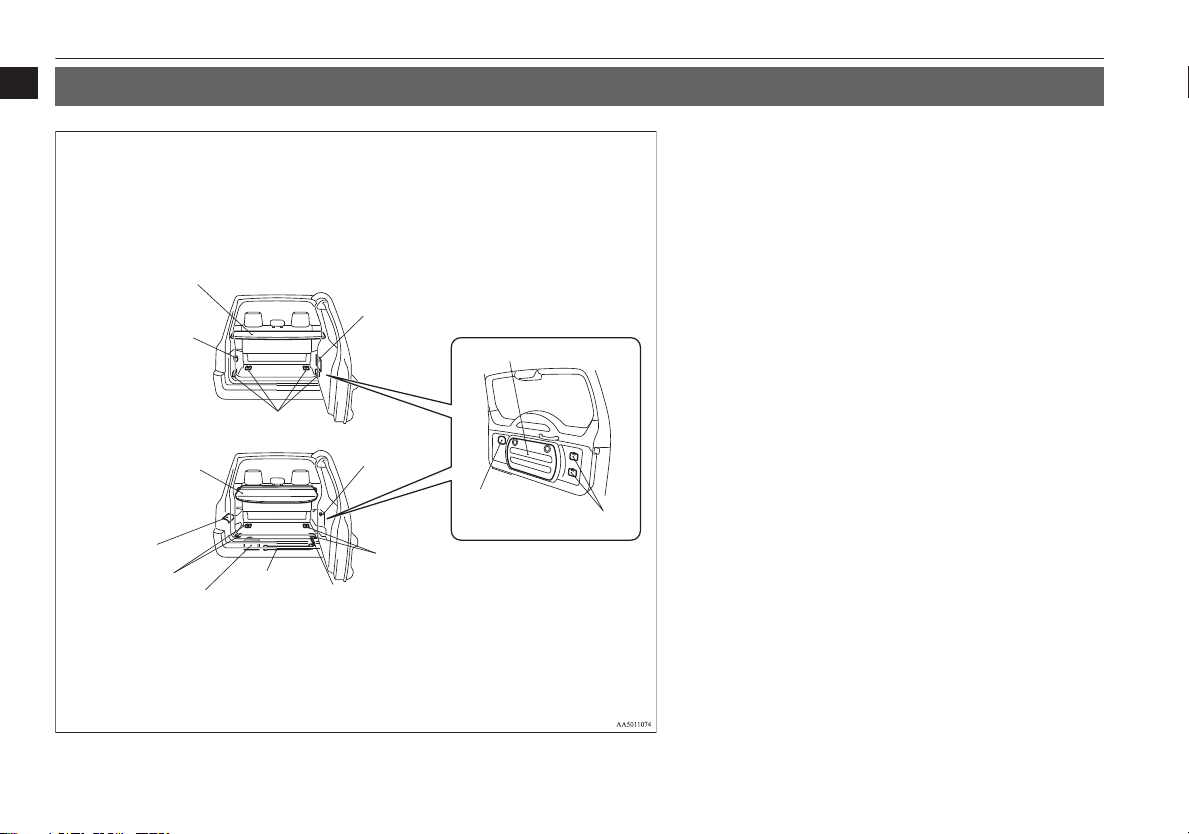
3-door models
1
2
3
4
5
6
7
8
9
10
12
11
13
14
15
5-door models
Luggage area
1
Luggage area
E00100401351
1. Accessory socket p. 7-77
2. Rear shelf* p. 7-86
3. Jack p. 8-07
Jack handle p. 8-07
Tool p. 8-07
4. Luggage hooks p. 7-88
5. Securing bands of warning triangle p. 7-88
6. Securing bolts of spare wheel garnish p. 8-10
7. Rear window washer fluid container p. 10-08
8. Accessory socket p. 7-77
9. Luggage hooks p. 7-88
10. Tool p. 8-07
11. Jack handle p. 8-07
12. Jack p. 8-07
13. Luggage hooks p. 7-88
14. Side box* p. 7-84
15. Cargo area cover* p. 7-86
1-08
Overview
OVWX17E1
Page 11
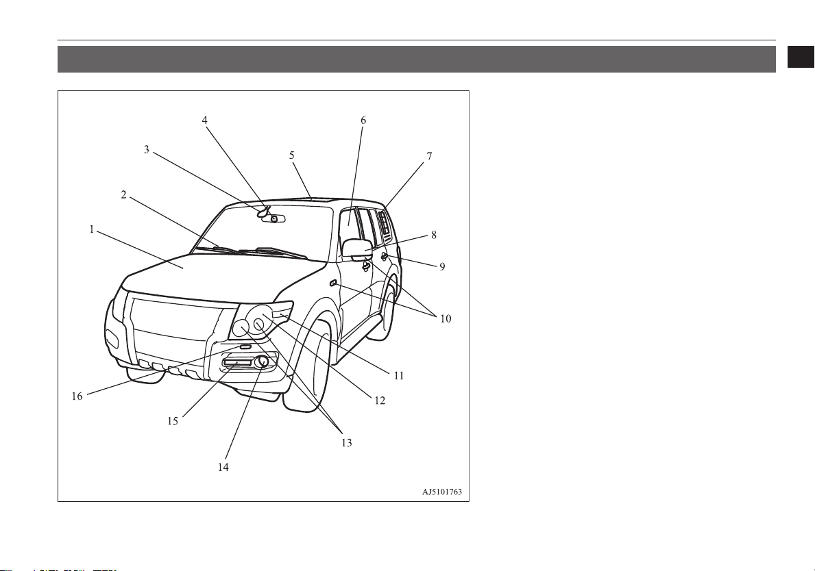
Outside (Front)
Outside (Front)
1
E00100507686
1. Engine compartment p. 11-14
Bonnet p. 10-03
2. Windscreen wiper and washer p. 5-44
3. Rain sensor* p. 5-45
4. Camera (for Automatic high-beam system)* p. 5-36
5. Sunroof* p. 3-19
6. Electric window control p. 3-16
7. Rear side/quarter window p. 3-18
Antenna p. 7-50
8. Outside rear-view mirrors p. 6-08
Approach lamps* p. 3-08
9. Locking and unlocking p. 3-06
Keyless entry system* p. 3-04
10. Side turn-signal lamps* p. 5-42, 10-23
11. Front turn-signal lamps p. 5-42, 10-23, 10-26
12. Position lamps* p. 5-34, 10-23, 10-26
13. Headlamps p. 5-34, 10-23, 10-25
14. Front fog lamps* p. 5-43, 10-23, 10-27
15. Position and Daytime running lamps* p. 5-34, 5-35, 10-23
16. Headlamp washer* p. 5-48
OVWX17E1
Overview
1-09
Page 12
3-door models 5-door models
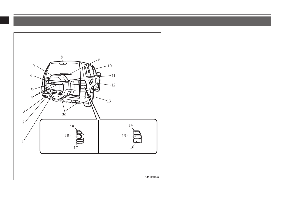
Outside (Rear)
1
Outside (Rear)
E00100507224
1. Rear fog lamp p. 5-43, 10-23, 10-29
2. Rear turn-signal lamps* p. 5-42, 10-23, 10-28
3. Tail lamps* p. 5-34, 10-23, 10-28
4. Licence plate lamps p. 5-34, 10-23, 10-29
5. Spare wheel garnish p. 8-10
6. Rear-view camera* p. 6-56
7. Spare wheel p. 8-10
8. High-mounted stop lamp p. 10-23, 10-29
9. Rear window wiper and washer p. 5-48
10. Antenna* p. 7-50
11. Backdoor p. 3-09
12. Fuel tank filler p. 2-03
13. Tyre inflation pressure p. 10-11
Tyre pressure monitoring system* p. 6-48
Changing tyres p. 8-09
Tyre rotation p. 10-13
Tyre chains p. 10-14
14. Corner and back sensor* p. 6-53
15. Rear turn-signal lamps* p. 5-42, 10-23, 10-28
16. Stop and tail lamps p. 5-34, 10-23, 10-28
Stop lamps* p. 10-23, 10-28
17. Reversing lamps p. 10-23, 10-28
18. Rear turn-signal lamps* p. 5-42, 10-23, 10-28
19. Reversing lamps p. 10-23, 10-28
20. Stop and tail lamps p. 5-34, 10-23, 10-28
Stop lamps* p. 10-23, 10-28
1-10
Overview
OVWX17E1
Page 13

General information
Fuel selection...................................................................................... 2-02
Filling the fuel tank.............................................................................2-03
Installation of accessories................................................................... 2-04
Modification/alterations to the electrical or fuel systems................... 2-05
Genuine parts...................................................................................... 2-05
Used engine oils safety instructions and disposal information...........2-06
Disposal information for used batteries.............................................. 2-06
2
OVWX17E1
Page 14
Fuel selection
Fuel selection
2
Recommended
fuel
CAUTION
For petrol-powered vehicles, the use of lea-
l
ded fuel can result in serious damage to the
engine and catalytic converter. Do not use
leaded fuel.
Diesel-powered vehicles are designed to use
l
only diesel fuel that meets the EN 590 standard.
Use of any other type of diesel fuel would
adversely affect the engine’s performance
and durability.
Petrol-powered vehicles
Unleaded petrol octane
number (EN228)
90 RON or higher
If the “PREMIUM FUEL
ONLY” label is attached to
the fuel tank filler door, fill
it up with premium fuel.
Diesel-powered vehicles
Cetane number (EN590)
51 or higher
E00200104901
CAUTION
For diesel-powered vehicles, if proper “win-
l
ter” fuel is not used in winter, the diesel preheat indication lamp may blink and the engine speed may not rise above the idling
speed because of fuel freezing. In this case,
keep the engine idling for about ten minutes,
then turn off the ignition switch and immediately turn it on again to confirm that the diesel preheat indication lamp is off. (Refer to
“Diesel preheat indication lamp” on page
5-09.)
NOTE
It is advisable to sufficiently warm up the
l
engine after starting it when the outside temperature is below zero °C.
Due to the separation of paraffin, the fluidity
l
of the fuel decreases considerably as the
temperature falls.
Because of this fact there are two kinds of
fuel: “summer” and “winter”.
This must be considered in winter use.
Select either of the two kinds of fuel in accordance with ambient temperature.
Above -5 °C: “Summer” diesel
Below -5 °C: “Winter” diesel
When travelling abroad, find out in advance
about the fuels served in local service stations.
NOTE
In petrol-powered vehicles, repeatedly driv-
l
ing short distances at low speeds can cause
deposits to form in the fuel system and engine, resulting in poor starting and poor acceleration.
If these problems occur, you are advised to
add a detergent additive to the gasoline
when you refuel the vehicle. The additive
will remove the deposits, thereby returning
the engine to a normal condition. Be sure to
use a MITSUBISHI MOTORS GENUINE
FUEL SYSTEM CLEANER. Using an unsuitable additive could make the engine malfunction. For details, please contact your
MITSUBISHI MOTORS Authorized Service Point.
Poor quality petrol can cause problems such
l
as difficult starting, stalling, engine noise
and hesitation. If you experience these problems, try another brand and/or grade of petrol.
If the check engine warning lamp flashes,
have the system checked as soon as possible
at a MITSUBISHI MOTORS Authorized
Service Point.
2-02
General information
OVWX17E1
Page 15
LHD
RHD
Filling the fuel tank
NOTE
In diesel-powered vehicles, poor-quality die-
l
sel fuel can cause deposits form in the injector, resulting in black smoke and rough
idling.
If these problems occur, you are advised to
add a cleaning additive to the diesel fuel
when you refuel the vehicle.
The additive will break up and remove the
deposits, thereby returning the engine to a
normal condition.
Be sure to use a MITSUBISHI MOTORS
GENUINE DIESEL FUEL SYSTEM
CLEANER. Using an unsuitable additive
could make the engine malfunction. For details, please contact your MITSUBISHI
MOTORS Authorized Service Point.
E10 type petrol
The petrol engines are compatible with E10
type petrol (containing 10 % ethanol) conforming to European standards EN 228.
E00203200019
CAUTION
Do not use more than 10 % concentration of
l
ethanol (grain alcohol) by volume.
Use of more than 10 % concentration may
lead to damage to your vehicle fuel system,
engine, engine sensors and exhaust system.
Filling the fuel tank
WARNING
When handling fuel, comply with the safe-
l
ty regulations displayed by garages and
filling stations.
Before removing the fuel tank filler tube
l
cap, be sure to get rid of your body’s static electricity by touching a metal part of
the car or fuel pump. Any static electricity
on your body could create a spark that ignites fuel vapour.
Perform the whole refueling process
l
(opening the fuel tank filler door, removing the fuel tank filler tube cap, etc.) by
yourself. Do not let any other person come
near the fuel tank filler. If you allowed a
person to help you and that person was
carrying static electricity, fuel vapour
could be ignited.
Do not move away from the fuel tank fill-
l
er door until refueling is finished. If you
moved away and did something else (for
example, cleaning your windscreen) partway through the refueling process, you
could pick up a fresh charge of static electricity.
If the fuel tank filler tube cap must be re-
l
placed, use only a MITSUBISHI
MOTORS genuine part.
Fuel tank capacity
E00200204087
5-door models: 88 litres
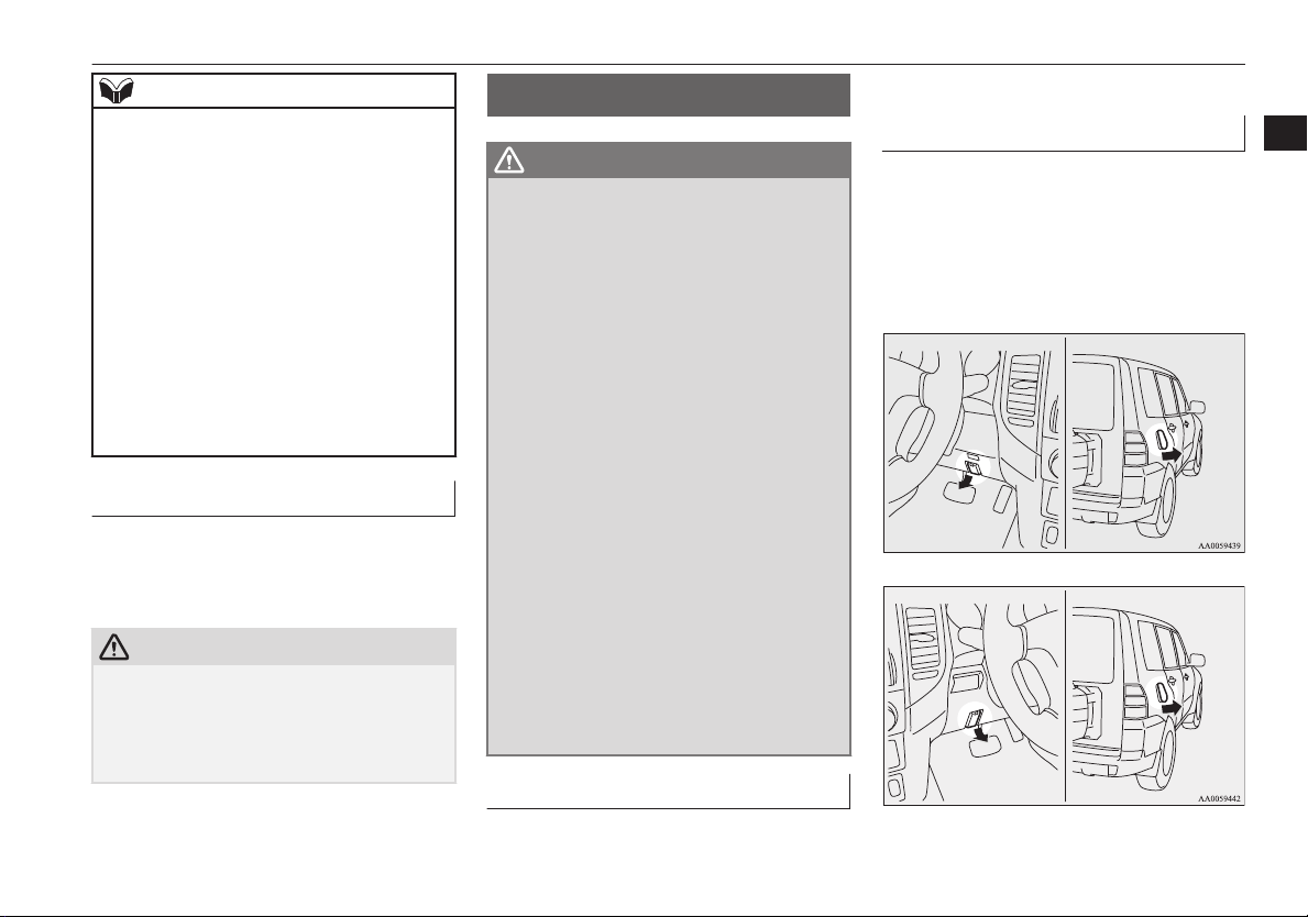
Refueling
1. Before filling with fuel, stop the engine.
2. The fuel tank filler is located on the rear
right side of your vehicle.
Open the fuel tank filler door with the
release lever located below the instrument panel.
2
3-door models: 69 litres
OVWX17E1
General information
2-03
Page 16
Installation of accessories
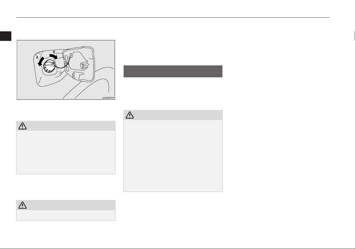
3. Open the fuel tank filler tube by slowly
turning the cap anticlockwise.
2
A- Remove
B- Close
CAUTION
Since the fuel system may be under pressure,
l
remove the fuel tank filler tube cap slowly.
This relieves any pressure or vacuum that
might have built up in the fuel tank. If you
hear a hissing sound, wait until it stops before removing the cap. Otherwise, fuel may
spray out, injuring you or others.
4. Insert the gun in the tank port as far as it
goes.
CAUTION
Do not tilt the gun.
l
2-04
General information
5. When the gun stops automatically, do
not fill with fuel any more.
6. To close, turn the fuel tank filler tube
cap slowly clockwise until you hear
clicking sounds, then gently push the
fuel tank filler door closed.
Installation of accessories
E00200302345
We recommend you to consult your
MITSUBISHI MOTORS Authorized Service
Point.
CAUTION
Your vehicle is equipped with a diagnosis
l
connector for checking and servicing the
electronic control system.
Do not connect a device other than a diagnosis tool for inspections and service to this
connector. Otherwise, the battery could be
discharged, the electronic devices of the vehicle could malfunction, or other unexpected
problems could result.
In addition, malfunctions caused by connecting a device other than a diagnosis tool may
not be covered under warranty.
OVWX17E1
The installation of accessories, optional
l
parts, should only be carried out within
the limits prescribed by law in your
country, and in accordance with the
guidelines fitting instructions and warnings contained within the documents accompanying the parts or accessories.
Improper installation of electrical com-
l
ponents may cause an electrical fire if
incorrectly fitted. Please refer to the
Modification/alteration to the electrical
or fuel systems section within this owner’s manual.
When installing the radio, for the re-
l
quired information (frequency, transmission output, installing procedure), consult a MITSUBISHI MOTORS Authorized Service Point.
If the frequency, transmission output and
installing condition are not appropriate,
it can adversely affect the electronic devices and could lead to unsafe vehicle
operation.
Using a cellular phone or radio set inside
l
the vehicle without an external antenna
may cause electrical system interference,
which could lead to unsafe vehicle operation.
Tyres and wheels which do not meet
l
specifications must not be used.
Refer to the “Specifications” section for
information regarding wheel and tyre
sizes.
Page 17
Modification/alterations to the electrical or fuel systems
When fitting accessories, ensure that
l
maximum gross vehicle weight and
maximum axle weight are not exceeded.
Important points!
Due to large number of accessory and replacement parts of different manufactures
available in the market, it is not possible, not
only for MITSUBISHI MOTORS, but also
for a MITSUBISHI MOTORS Authorized
Service Point, to check whether the attachment or installation of such parts affects the
overall safety of your MITSUBISHI-vehicle.
Even when such parts are officially authorized, for example by a “general operators
permit” (an appraisal for the part) or through
the execution of the part in an officially approved manner of construction, or when a
single operation permit following the attachment or installation of such parts, it cannot be
deduced from that alone, that the driving
safety of your vehicles has not been affected.
Consider also that there basically exists no liability on the part of the appraiser or the official. Only in the case of parts (MITSUBISHI
MOTORS original replacement or exchange
parts as well as MITSUBISHI MOTORS
genuine accessories) that are recommended
and released by a MITSUBISHI MOTORS
Authorized Service Point and that are attached or installed by a MITSUBISHI MOTORS
Authorized Service Point can you assume,
that optimal safety has been provided. The
same also pertains to modifications of
MITSUBISHI vehicles with respect to the
production specifications. For your own safety, in such cases, you should only undertake
modifications according to the recommendations of a MITSUBISHI MOTORS Authorized Service Point.
Modification/alterations to
the electrical or fuel systems
E00200400254
MITSUBISHI MOTORS has always manufactured safe, high quality vehicles. In order
to maintain this safety and quality, it is important that any accessory that is to be fitted,
or any modifications carried out which involve the electrical or fuel systems, should be
carried out in accordance with MITSUBISHI
MOTORS guidelines.
CAUTION
If the wiring interferes with any part of the
l
vehicle bodywork or improper installation
methods are used, i.e. protective fuses not
installed, etc.), electronic devices may be adversely affected, possibly resulting in an
electrical fire or other failures that may
cause an accident.
Genuine parts
E00200500617
MITSUBISHI MOTORS has gone to great
lengths to bring you a superbly crafted automobile offering the highest quality and dependability.
Use MITSUBISHI MOTORS genuine parts,
designed and manufactured to maintain your
MITSUBISHI MOTORS automobile at top
performance. MITSUBISHI MOTORS genuine parts are identified by this mark and are
available at all MITSUBISHI MOTORS Authorized Service Points.
2
OVWX17E1
General information
2-05
Page 18
Used engine oils safety instructions and disposal information
Used engine oils safety
instructions and disposal
2
information
WARNING
Prolonged and repeated contact may
l
cause serious skin disorders, including
dermatitis and cancer.
Avoid contact with the skin as far as pos-
l
sible and wash thoroughly after any contact.
Keep used engine oils out of reach of chil-
l
dren.
Protect the environment
It is illegal to pollute drains, water courses
and soil. Use authorized waste collection facilities, including civic amenity sites and garages providing facilities for disposal of used
oil and used oil filters. If in doubt, contact
your local authority for advice on disposal.
E00200600025
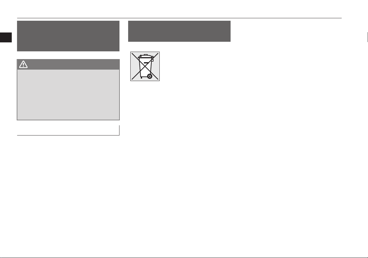
Disposal information for used batteries
E00201300016
Your vehicle contains batteries and/or accumulators.
Do not mix with general
household waste.
For proper treatment, recovery and recycling of used batteries, please take them to applicable collection points, in
accordance with your national legislation and the Directives 2006/66/EC.
By disposing of these batteries correctly, you will help to
save valuable resources and
prevent any potential negative effects on human health
and the environment which
could otherwise arise from
inappropriate waste handling.
2-06
General information
OVWX17E1
Page 19

Locking and unlocking
Keys.................................................................................................... 3-02
Electronic immobilizer (Anti-theft starting system)........................... 3-03
Keyless entry system*.........................................................................3-04
Doors...................................................................................................3-06
Central door locks............................................................................... 3-07
“Child-protection” rear doors (5-door models)...................................3-08
Approach lamps*................................................................................ 3-08
Backdoor............................................................................................. 3-09
Security alarm system*....................................................................... 3-11
Electric window control......................................................................3-16
Rear side/quarter window................................................................... 3-18
Sunroof*..............................................................................................3-19
3
OVWX17E1
Page 20
Type 1
Type 2
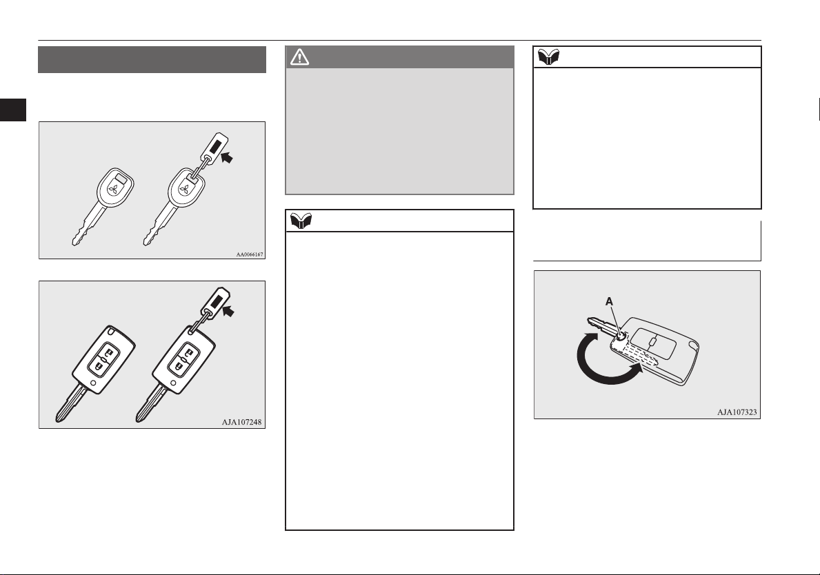
Keys
Keys
The key fits all locks.
3
E00300103631
WARNING
When taking a key on flights, do not press
l
any switches on the key while on the
plane. If a switch is pressed on the plane,
the key emits electromagnetic waves,
which could adversely affect the plane’s
flight operation.
When carrying a key in a bag, be careful
that no switches on the key can be easily
pressed by mistake.
NOTE
The key number is stamped on the tag as in-
l
dicated in the illustration.
Make a record of the key number and store
the key and key number tag in separate places, so that you can order a key in the event
the original keys are lost.
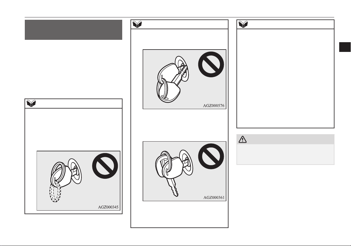
The key is a precision electronic device with
l
a built-in signal transmitter. Please observe
the following in order to prevent damage.
Do not leave where it may be exposed to
•
heat caused by direct sunlight, such as on
top of the dashboard.
Do not take the remote control transmitter
•
apart.
Do not excessively bend the key or sub-
•
ject it to strong impacts.
Keep the remote control transmitter dry.
•
Keep away from magnetic objects such as
•
key rings.
Keep away from devices that produce
•
magnetism, such as audio systems, computers and televisions.
NOTE
Do not clean with ultrasonic cleaners.
•
Do not leave the key where it may be ex-
•
posed to high temperature or high humidity.
The engine is designed so that it will not
l
start if the ID code registered in the immobilizer computer and the key’s ID code do
not match. Refer to the section entitled
“Electronic immobilizer” section for details
and key usage.
To use and carry the key (Type
2)
When using the key, press the button (A) on
the body.
When carrying the key, fold the key while
pressing the button.
3-02
Locking and unlocking
OVWX17E1
Page 21
Electronic immobilizer (Anti-theft starting system)
Electronic immobilizer
(Anti-theft starting system)
E00300203472
The electronic immobilizer is designed to
significantly reduce the possibility of vehicle
theft. The purpose of the system is to immobilize the vehicle if an invalid start is attempted. A valid start attempt can only be achieved by using a key “registered” to the immobilizer system.
NOTE
In the following cases, the vehicle may not
l
be able to receive the registered ID code
from the registered key and the engine may
not start.
When the key contacts a key ring or other
•
metallic or magnetic object
NOTE
When the key grip contacts metal of an-
•
other key
When the key contacts or is close to other
•
immobilizing keys (including keys of other vehicles)
NOTE
not start, we recommend you to contact your
MITSUBISHI MOTORS Authorized Service Point.
Electronic immobilizer is not compatible
l
with remote starting systems. Use of these
systems may result in vehicle starting problems and a loss of security protection.
If you lose your key, order a key from your
l
MITSUBISHI MOTORS Authorized Service Point as soon as possible. To obtain a replacement or extra spare key, take your vehicle and all remaining keys to your
MITSUBISHI MOTORS Authorized Service Point. All the keys have to be re-registered in the immobilizer computer unit. The
immobilizer can register up to 8 different
keys for use.
CAUTION
Don’t make any alterations or additions to
l
the immobilizer system; alterations or additions could cause failure of the immobilizer.
3
In cases like these, remove the object or additional key from the vehicle key. Then try
again to start the engine. If the engine does
OVWX17E1
Locking and unlocking
3-03
Page 22
Keyless entry system*
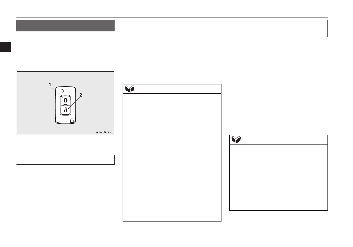
Keyless entry system*
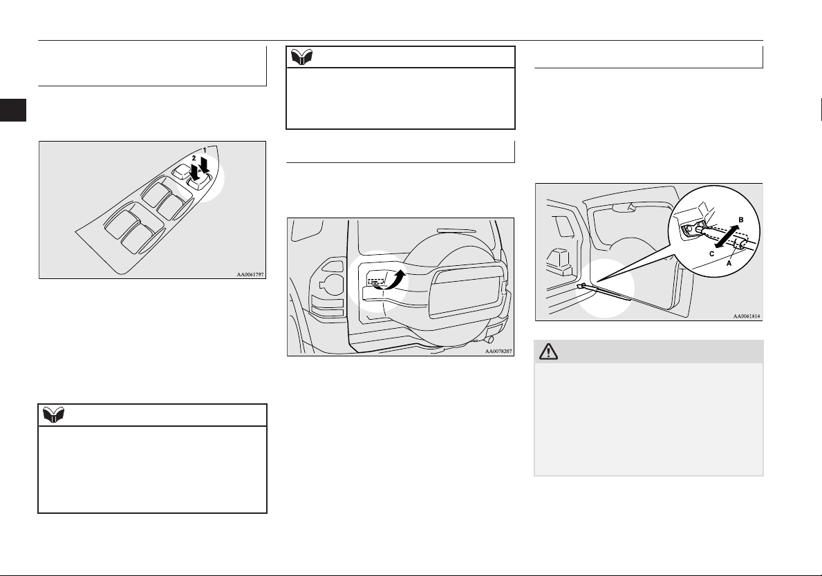
Press the remote control switch, and all doors
(including the backdoor) will be locked or
3
unlocked as desired. It is also possible to operate the outside rear-view mirrors.
1- LOCK switch
2- UNLOCK switch
To lock
Press the LOCK switch (1), and all doors (including the backdoor) will be locked. When
they are locked with the room lamp switch at
the middle position (DOOR), the room lamp
and the turn-signal lamps blink once.
E00300303789
To unlock
Press the UNLOCK switch (2), and all doors
(including the backdoor) will be unlocked.
When they are unlocked with the room lamp
switch at the middle position (DOOR), the
room lamp will be turned on for approximately 15 seconds and the turn-signal lamps
will blink twice.
NOTE
If the UNLOCK switch (2) is pressed and no
l
door (including the backdoor) is opened
within approximately 30 seconds: relocking
will automatically occur.
It is possible to modify functions as follows:
l
For further information, please contact your
MITSUBISHI MOTORS Authorized Service Point.
The time for automatic relocking can be
•
changed.
The confirmation function (blinking of
•
the turn-signal lamps) can be set to operate only when the doors and backdoor are
locked or only when the doors and backdoor are unlocked.
The confirmation function (this indicates
•
locking or unlocking of the doors and
backdoor with the blink of the turn-signal
lamps) can be deactivated.
The number of times the turn-signal
•
lamps are flashed by the confirmation
function can be changed.
Operation of the outside rearview mirrors
To fold
Within 30 seconds of locking the doors and
backdoor using the LOCK switch (1), press
the LOCK switch twice rapidly to fold the
outside rear-view mirrors.
To extend
Within 30 seconds of unlocking the doors
and backdoor using the UNLOCK switch (2),
press the UNLOCK switch twice rapidly to
return the outside rear-view mirrors to their
extended positions.
NOTE
The keyless entry system does not operate in
l
the following conditions:
The key is left in the key cylinder.
•
The door (including the backdoor) is
•
open.
The remote control switch will operate with-
l
in approximately 4 m from the vehicle.
However, the operating range of the remote
control switch may change if the vehicle is
located near a power station, or radio/TV
broadcasting station.
3-04
Locking and unlocking
OVWX17E1
Page 23
Keyless entry system*
NOTE
If the remote control switch is operated at
l
the correct distance from the vehicle, but the
doors (including the backdoor) are not
locked/unlocked in response, the battery
may be exhausted.
For further information, please consult your
MITSUBISHI MOTORS Authorized Service Point.
If you replace the battery yourself, refer to
“Procedure for replacing the remote control
switch battery” on page 3-05.
If your remote control switch is lost or dam-
l
aged, please contact your MITSUBISHI
MOTORS Authorized Service Point for a replacement remote control switch.
If you wish to add a remote control switch,
l
we recommend you to contact your
MITSUBISHI MOTORS Authorized Service Point.
A maximum of 4 remote control switches
are available for your vehicle.
Procedure for replacing the remote control switch battery
E00309501298
WARNING
Danger of explosion if battery is incor-
l
rectly replaced.
Replace only with the same battery or an
equivalent type.
CAUTION
Never disassemble or remove any inside
l
parts of the keyless entry key other than described below.
Because there is a possibility that it may become impossible to reassemble.
When the remote control switch case is
l
opened, be careful to keep water, dust, etc.
out.
NOTE
You may purchase a replacement battery at
l
an electric appliance store.
A MITSUBISHI MOTORS Authorized
l
Service Point can replace the battery for you
if you prefer.
1. Before replacing the battery, remove
static electricity from your body by
touching a metal part such as doorknob
of the room.
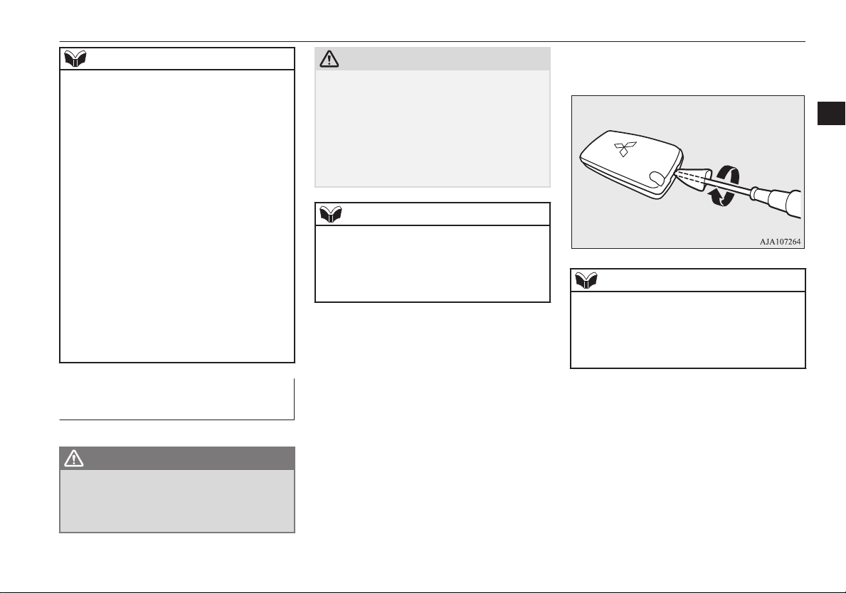
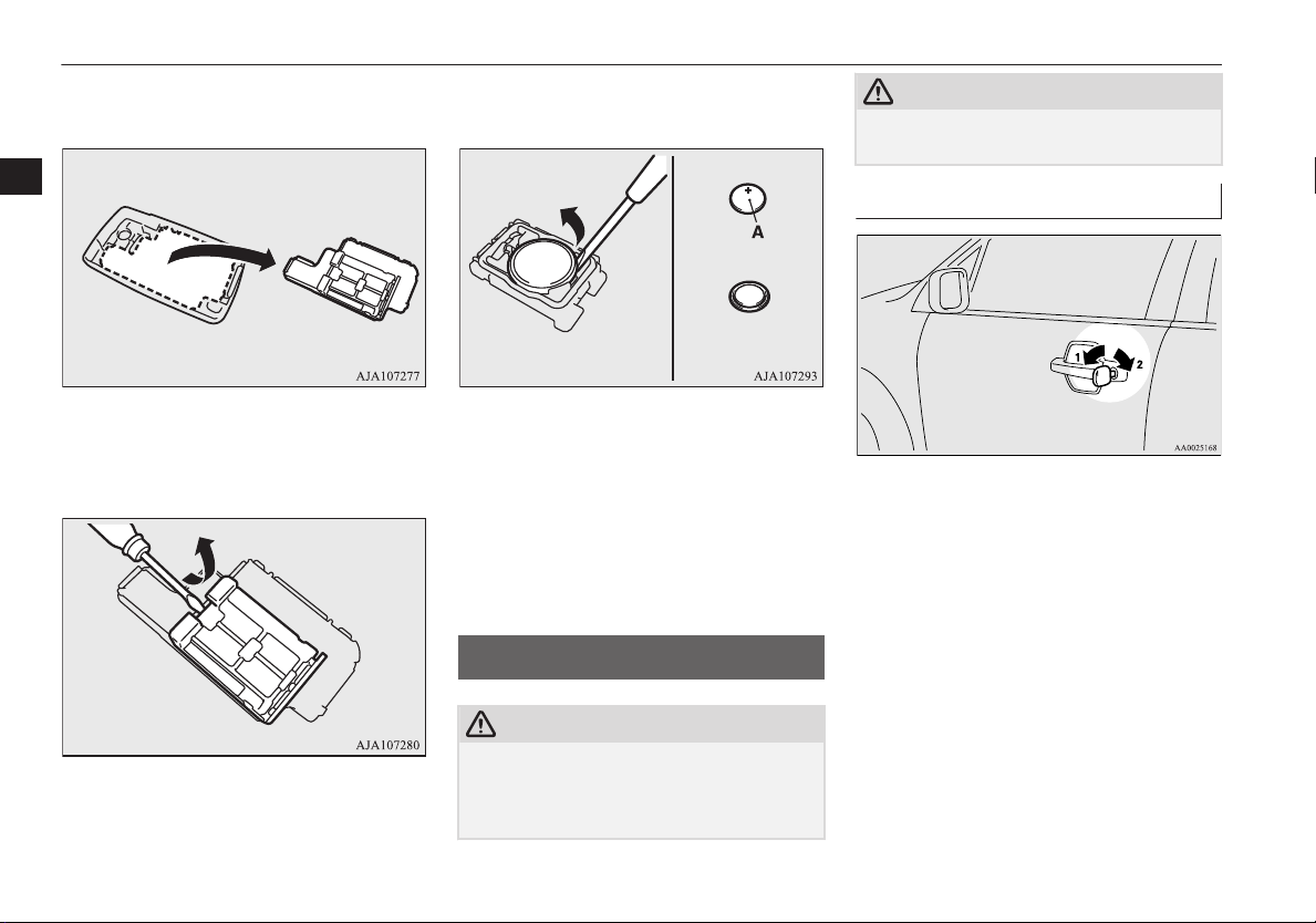
2. With the MITSUBISHI mark facing
you, insert the cloth-covered tip of a
straight blade (or minus) screwdriver in-
to the notch in the remote control switch
case and use it to open the case.
NOTE
Be sure to perform the procedure with the
l
MITSUBISHI mark facing you. If the
MITSUBISHI mark is not facing you when
you open the remote control switch case, the
switches may come out.
3
OVWX17E1
Locking and unlocking
3-05
Page 24
+ side
- side
Coin type battery
CR1616
Doors
3. Remove the remote control transmitter
from the remote control switch case.
3
4. Open the remote control transmitter by
using a minus screwdriver as shown in
the illustration.
5. Remove the old battery.
6. Install a new battery with the + side (A)
down.
7. Close the remote control transmitter
firmly.
8. Place the remote control transmitter in
the remote control switch case, then securely close the remote control switch
case.
9. Check the keyless entry system to see
that it works.
Doors
E00300401177
CAUTION
Make sure the doors are closed: driving with
l
doors not completely closed is dangerous.
Never leave children in the vehicle unatten-
l
ded.
CAUTION
Be careful not to lock the doors while the
l
key is inside the vehicle.
To lock or unlock with the key
1- Lock
2- Unlock
3-06
Locking and unlocking
OVWX17E1
Page 25
Central door locks
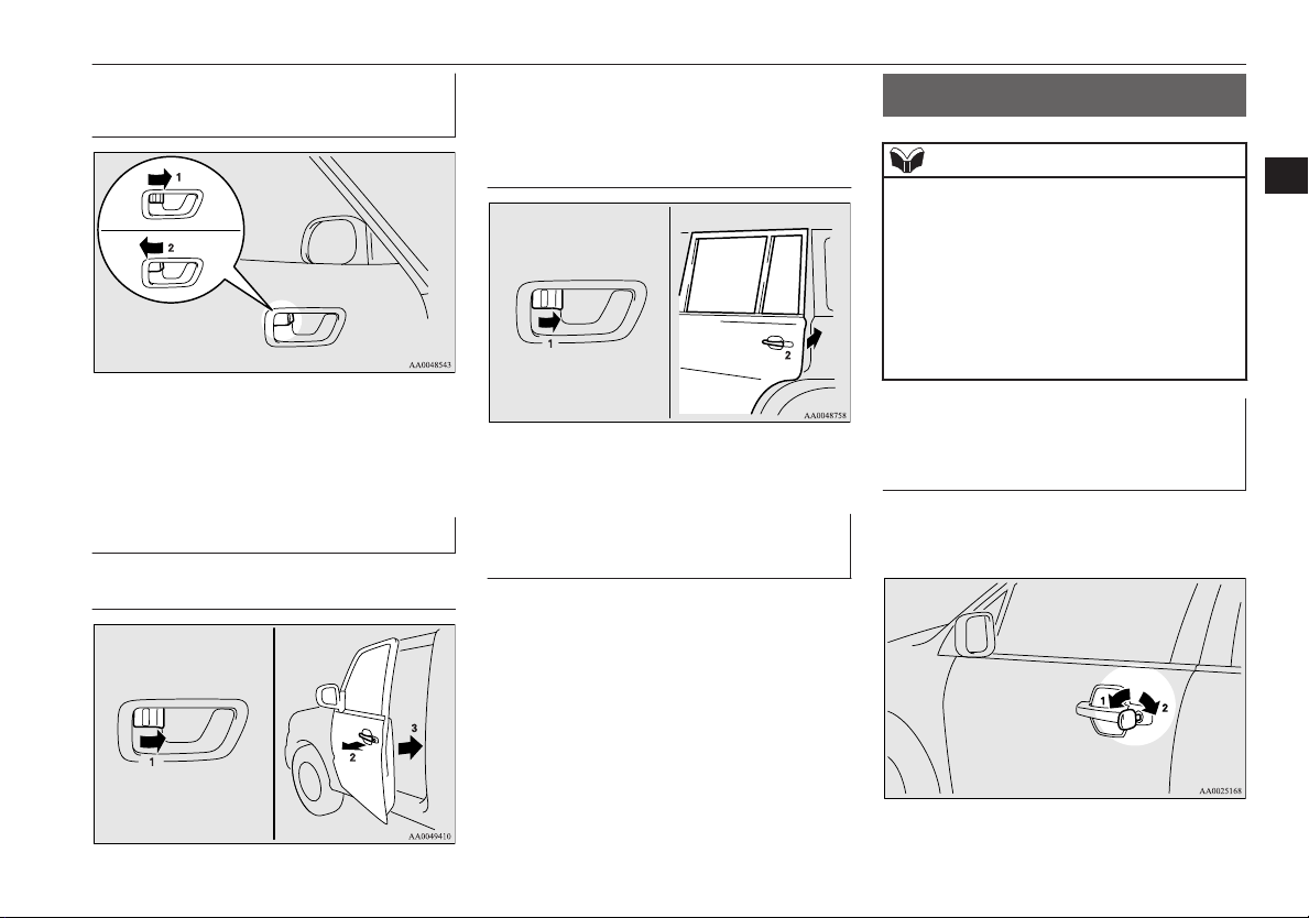
To lock or unlock from inside the vehicle
1- Lock
2- Unlock
Pull the inside door handle towards you to
open the door.
To lock without using the key
Front door
Set the inside lock knob (1) to the locked position, and while pulling the outside handle
up (2), close the door (3).
Rear door (5-door models)
Set the inside lock knob (1) to the locked position, and close the door (2).
“Forgotten-key-prevention” mechanism
E00300600273
If the key is in the ignition switch when you
push the lock knob forward with the driver’s
door open, the lock knob will automatically
return to the unlocked position.
Central door locks
E00300801692
NOTE
Each of the doors can be locked or unlocked
l
independently by using the inside lock knob.
Repeated continuous operation between lock
l
and unlock could activate the central door
locking systems built-in protection circuit
and prevent the system from operating.
If this occurs, wait approximately 1 minute
before operating the central door lock switch
or the key.
Driver’s door with key (except for vehicles with keyless entry system)
Using the key on the driver’s door locks or
unlocks all doors (including the backdoor).
3
OVWX17E1
1- Lock
2- Unlock
Locking and unlocking
3-07
Page 26
“Child-protection” rear doors (5-door models)
Driver’s door with central door lock switch
Using the central door lock switch locks or
3
unlocks all doors (including the backdoor).
1- Lock
2- Unlock
“Child-protection” rear
doors (5-door models)
E00300900869
1- Lock
2- Unlock
Child protection helps prevent the rear doors
from being opened accidentally from the inside.
If the lever is set to the locked position, the
rear door cannot be opened using the inside
handle, but only with the outside handle.
If the lever is set to the “Unlock” position,
the child protection mechanism does not
function.
CAUTION
When driving with a child in the rear seat,
l
please use the child protection to prevent accidental door opening which may cause an
accident.
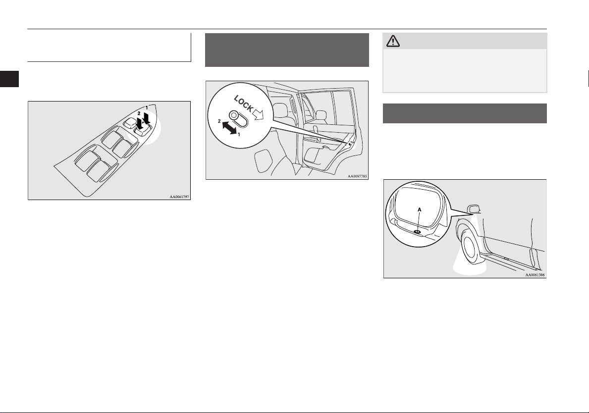
Approach lamps*
E00306100195
The lamps (A) in the bottom of each mirror
come on to illuminate road surface while
people are entering or exiting the vehicle.
These lamps turn on/off as follows:
The lamps come on for approximately
l
15 seconds when all of the doors (including the backdoor) are unlocked using the central door lock function or the
keyless entry system (if so equipped).
3-08
Locking and unlocking
OVWX17E1
Page 27
When any door or the backdoor is
l
opened, the lamp comes on for approximately 2 minutes.
If all of the doors (including the backdoor) are closed while the lamps are on,
the lamps go off 30 seconds later.
NOTE
The lamps go off immediately if any of the
l
following actions is taken while the lamps
are on.
The ignition switch is turned to the “ON”
•
position.
All of the doors (including the backdoor)
•
are locked using the central door lock
function.
All of the doors (including the backdoor)
•
are locked using the keyless entry system
(if so equipped).
Backdoor
WARNING
It is dangerous to drive with the backdoor
l
open since carbon monoxide (CO) gas can
enter the cabin. You cannot see or smell
CO. It can cause unconsciousness and
even death.
E00301300424
CAUTION
When the backdoor is open, the rear-right
l
combination lamp is obscured by the spare
wheel.
If the backdoor is opened while the vehicle
is parked on the road, alert other road users
to the vehicle’s presence using a warning triangle or other device as required by local
legislation.
When closing the backdoor, always ensure
l
your or other person’s fingers cannot be
caught by the backdoor.
NOTE
The backdoor is equipped with an oil damp-
l
er type backdoor stopper, enabling you to
hold the backdoor at a desired position.
While opening or closing the backdoor, you
l
may feel slight resistance. This is a structural
feature of the backdoor stopper that supports
the backdoor and does not indicate any abnormality.
Backdoor
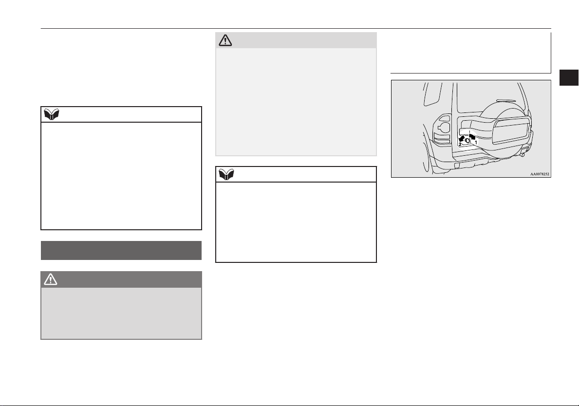
To lock or unlock from outside the vehicle (Except for vehicles with keyless entry system)
3
1- Lock
2- Unlock
OVWX17E1
Locking and unlocking
3-09
Page 28
Backdoor
To lock or unlock from inside the vehicle
The backdoor can be locked or unlocked by
3
using the central door lock switch.
1- Lock
2- Unlock
Vehicles without keyless entry system, if the
backdoor is locked or unlocked by using the
central door lock switch, it can still be locked
or unlocked with the key.
NOTE
Repeated continuous operating between lock
l
and unlock could cause the central door
lock’s built-in protection circuit to prevent
the system from operating. If this occurs,
wait approximately 1 minute before operating the central door lock switch.
NOTE
When the luggage compartment lamp is set
l
to the [•] position, the luggage compartment
lamp illuminates when the backdoor is
opened and turns off when it is closed.
To open
Pull the outside handle towards you to open
the backdoor.
Backdoor stopper
Open the backdoor fully and then move the
locking tube (A) to the LOCK position (B);
this will ensure that the backdoor remains in
the fully opened position. To subsequently
release the stopper, move the locking tube
back to the UNLOCK position (C).
CAUTION
When closing the backdoor, be careful not to
l
trap your hands.
Before closing the backdoor, make sure that
l
the locking tube (A) is in the UNLOCK position (C). Closing the backdoor with the
locking tube (A) in the LOCK position (B)
may damage the backdoor stopper, rendering
the backdoor unable to be closed.
3-10
Locking and unlocking
OVWX17E1
Page 29
Security alarm system*
Security alarm system*
E00301500657
The security alarm system is designed to prevent unlawful entry into the vehicle. It will
alert people nearby if a door, the backdoor, or
the bonnet is opened when the vehicle has
not been unlocked using the keyless entry
system.
Also, the alarm will be activated if any of the
following occur.
Attempt an unlawful moving of the vehi-
l
cle. (the vehicle inclination detection
function)
Detect a motion in the vehicle. (the inte-
l
rior intrusion detection function)
Disconnect the battery terminal.
l
The security alarm system is set to “active”
when the vehicle leaves the factory.
When making changes to the settings, please
follow the procedure listed in the section titled “Changing the system settings” on page
3-12.
CAUTION
Do not modify or add parts to the security
l
alarm system.
Doing so could cause the security alarm to
malfunction.
NOTE
The alarm system will not be activated if the
l
doors (including the backdoor) have been
locked using a key or the central door lock
switch (instead of the keyless entry system).
If the turn-signal lamps do not blink after the
l
locking and unlocking operation using the
keyless entry system, the security alarm system may be malfunctioning.
Have the vehicle inspected at a
MITSUBISHI MOTORS Authorized Service Point.
In the following situations, the security
l
alarm system could be more likely to be accidentally activated.
Using a car wash
•
Taking the vehicle on a ferry
•
Parking in an automated car park
•
Leaving someone or a pet in the vehicle
•
Leaving a window, door, or the sunroof
•
open
Leaving an unstable object such as a stuf-
•
fed toy or accessory in the vehicle
Suffering a continuous impact or vibra-
•
tion by hail, thunder, etc.
The sensitivity of the vehicle inclination de-
l
tection function and the interior intrusion detection function can be adjusted. For details,
please contact a MITSUBISHI MOTORS
Authorized Service Point.
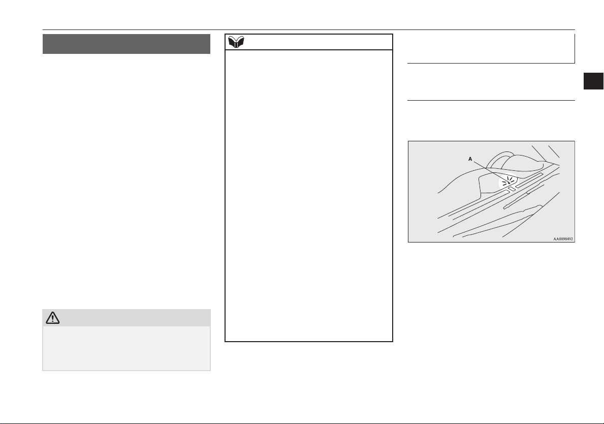
The security alarm has four modes:
System preparation mode (approx. 20 seconds)
(The buzzer sounds intermittently, and the security alarm indicator (A) blinks)
The system preparation time extends from
the point at which all of the doors (including
the backdoor) are locked by the keyless entry
switch to the point at which the system activation mode goes into effect.
During this time, it is possible to temporarily
open a door without using the keyless entry
system and without causing the alarm to
sound (for example, when you forget something inside the vehicle or realize that a window is open).
3
OVWX17E1
Locking and unlocking
3-11
Page 30
Security alarm system*
System armed mode
(The buzzer stops, and the security alarm indicator continues to blink slowly)
Once the system preparation mode has ended,
3
the system armed mode starts. If an unlawful
opening of any of the doors (including the
backdoor) or the bonnet is detected during
the system armed mode, the alarm will be activated to warn people around the vehicle of
an abnormal condition.
Also, if unlawful moving of the vehicle is attempted or a vehicle intrusion is detected, the
alarm will be activated.
Alarm activation
The turn-signal lamps blink and the siren
sounds for approximately 30 seconds. Refer
to “Alarm activation” on page 3-15.
NOTE
The alarm will resume if unlawful actions
l
are taken again, even if the alarm has stopped.
System cancellation
It is possible to cancel the system activation
during the system preparation mode or the
system armed mode.
In addition, it is possible to cancel the alarm
once it has been activated.
Refer to “Cancelling the system” on page
3-15, “Cancelling the alarm” on page 3-16.
NOTE
When lending the vehicle to another person
l
or allowing the vehicle to be driven by
someone who is unfamiliar with the security
alarm system, be sure to give the person a
proper explanation of the security alarm system or set the security alarm system to the
“inactive” mode.
If a person who is unfamiliar with the security alarm system accidentally unlocked the
vehicle, causing the alarm to sound, the
alarm would be a nuisance to people nearby.
Changing the security alarm settings
It is possible to set the security alarm to the
“active” mode or “inactive” mode.
Follow the procedure below.
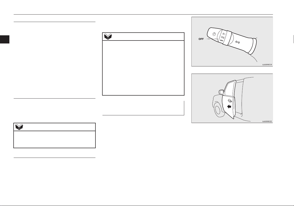
1. Remove the key from the ignition
switch.
2. Place the lamp switch in the “OFF” position, and leave the driver’s door open.
E00301601378
3. Pull the windscreen wiper and washer
switch towards you and hold it there.
3-12
Locking and unlocking
OVWX17E1
Page 31

Security alarm system*
(Since the ignition switch is in the
“LOCK” position, washer fluid will not
be sprayed.)
4. After approximately 10 seconds, the
buzzer will make a sound. Keep the
windscreen wiper and washer switch
pulled towards you.
(If the windscreen wiper and washer
switch was released, the setting change
mode would be cancelled. To start over,
perform the procedure again from step
3.)
5. When the buzzer stops, with the windscreen wiper and washer switch still
pulled towards you, press the UNLOCK
switch (A) on the keyless entry switch to
select the security alarm settings mode.
The settings mode can be toggled by
pressing the UNLOCK switch. The
mode can be confirmed from the number
of times the buzzer sounds.
Number of
times the buzzer
sounds
1 Alarm inactive
3 Alarm active
6. Any of the following operations can be
used to terminate the system settings
change mode.
• Releasing the windscreen wiper and
washer switch.
• Closing the driver’s door.
• Inserting the key into the ignition
switch.
Security alarm settings
mode
• Placing the lamp switch in any position other than “OFF”.
• Allowing 30 seconds to pass without making any changes to the settings.
NOTE
If anything with regard to making changes to
l
the security alarm system settings is hard to
understand, please consult a MITSUBISHI
MOTORS Authorized Service Point.
Avoid leaving valuable items inside the ve-
l
hicle even when the security alarm system
has been set to the “active” mode.
Setting the system
Once the security alarm system has been set
to the “active” mode, follow the procedure
below to set the system to the system armed
mode.
1. Remove the key from the ignition
switch.
2. Exit the vehicle and close all of the
doors (including the backdoor) and the
bonnet.
3. Press the LOCK switch (A) on the keyless entry switch in order to lock all the
doors (including the backdoor).
E00301702028
3
OVWX17E1
Locking and unlocking
3-13
Page 32

Security alarm system*
NOTE
The system preparation mode is not activa-
l
ted when all of the doors (including the
3
By locking the vehicle using the keyless
entry system, the system preparation
mode is activated. The buzzer sounds intermittently for confirmation, and the security alarm indicator (B) on the instrument panel blinks.
backdoor) have been locked using a method
other than the keyless entry system (namely
a key or the central door lock switch).
If the bonnet is open, the security alarm indi-
l
cator illuminates, and the system does not
enter the system armed mode. When the
bonnet is closed, the system enters the system preparation mode, and after approximately 20 seconds the system enters the system armed mode.
4. The buzzer stops after approximately 20
seconds, and when the blinking of the
security alarm indicator starts to slow
down, the system armed mode goes into
effect. The security alarm indicator continues to blink during the system armed
mode.
NOTE
The security alarm system can be activated
l
when people are riding inside the vehicle or
when the windows are open. To prevent accidental activation of the alarm, do not set
the system to the system armed mode while
people are riding in the vehicle.
NOTE
With the system in the system armed mode,
l
if any method other than the keyless entry
system is used (namely a key or the central
door lock switch) to unlock the vehicle and
open any of the doors (including the backdoor), the room lamp does not illuminate.
To deactivate the vehicle inclination detection function and
the interior intrusion detection
function
The vehicle inclination detection function
and the interior intrusion detection function
can be deactivated when parking in automated car parks, when leaving pets in the vehicle or when leaving the vehicle with the windows slightly open.
1. Remove the key from the ignition
switch.
2. Raise and hold the wiper and washer
switch to the “MIST” position for approximately 3 seconds. The buzzer will
sound once and the function will be deactivated.
To activate the function again, raise and hold
the wiper and washer switch to the “MIST”
position for approximately 3 seconds.
E00312100204
3-14
Locking and unlocking
OVWX17E1
Page 33

Security alarm system*
The buzzer will sound twice and the function
will be activated.
NOTE
The function will be activated again using
l
one of the following methods.
Unlock the doors (including the back-
•
door) using the keyless entry system.
Turn the ignition switch to the “ON” or
•
“ACC” position.
Cancelling the system
The following methods can be used to cancel
the system when it is in the system preparation mode or the system armed mode.
Pressing the UNLOCK switch on the
l
keyless entry switch.
Turning the ignition switch to the “ON”
l
or “ACC” position.
E00301800399
Opening any of the doors (including the
l
backdoor) when the system is in the system preparation mode, or inserting the
key into the ignition switch.
NOTE
If the bonnet is opened during the system
l
preparation mode, the system preparation
mode is suspended. The system returns to
the system preparation mode when the bonnet is closed.
If the battery terminals are disconnected
l
while the system is in the system preparation
mode, the memory will be erased.
It is possible to register up to 4 remote con-
l
trol switches. As long as they are registered,
any of the 4 remote control switches, other
than the one used to activate the system, can
be used to cancel the system.
If you want to register additional remote
control switches, please contact a
MITSUBISHI MOTORS Authorized Service Point.
NOTE
The activation distance for the keyless entry
l
system is approximately 4 m.
If it is not possible to lock or unlock the vehicle by pressing the switch at the correct
distance or the security alarm system cannot
be set or cancelled using the switch, the battery may need to be replaced.
For further information, please consult a
MITSUBISHI MOTORS Authorized Service Point.
If you replace the battery yourself, refer to
“Procedure for replacing the remote control
switch battery” on page 3-05.
If the UNLOCK switch is pressed and no
l
door is (including the backdoor) opened
within 30 seconds, the doors will automatically relock. In this case as well, the system
preparation mode will go into effect.
The time between pressing the UNLOCK
switch and automatic locking can be adjusted. Consult a MITSUBISHI MOTORS Authorized Service Point.
Alarm activation
When the system is in the system armed
mode, the alarm will be activated as follows
if the vehicle is unlocked and any of the
doors (including the backdoor) or bonnet is
opened using a method other than pressing
the UNLOCK switch on the keyless entry
switch.
E00301900840
3
OVWX17E1
Locking and unlocking
3-15
Page 34

Driver’s switch (LHD)
Driver’s switch (RHD)
Electric window control
1. The alarm will be activated for approximately 30 seconds. The turn-signal
lamps will flash, and the siren will sound
intermittently.
3
2. The alarm will resume if unlawful actions are taken again, even if the alarm
has stopped.
NOTE
The interior lamp will not come on while the
l
alarm is sounding.
Cancelling the alarm
It is possible to halt the activation of an alarm
using the following methods:
E00302000356
Pressing the LOCK or UNLOCK switch
l
on the keyless entry switch.
(After pressing the LOCK switch, the
vehicle will lock if all the doors (including the backdoor) are closed, after which
the system preparation mode will once
again go into effect.)
Turning the ignition switch to the “ON”
l
or “ACC” position.
NOTE
When the ignition switch is turned to the
l
“ON” position, the buzzer sounds 4 times.
This operation indicates that the alarm was
activated while the vehicle was parked.
Please check the inside of the vehicle to confirm that nothing was stolen.
Even if the battery is disconnected, the alarm
l
activation memory will not be erased.
Electric window control
E00302200185
The electric windows can only be operated
with the ignition switch in the “ON” position.
Electric window control switch
E00302301226
Each door window opens or closes while the
corresponding switch is operated.
1- Driver’s door window
2- Front passenger’s door window
3- Rear left door window (5-door models)
4- Rear right door window (5-door models)
5- Lock switch
3-16
Locking and unlocking
OVWX17E1
Page 35

Passenger’s switch
Electric window control
Driver’s switches
The driver’s switches can be used to operate
all door windows.
A window can be opened or closed by operating the corresponding switch.
Press the switch down to open the window,
and pull up the switch to close it.
If the switch for the driver’s window is fully
pressed down/pulled up, the door window automatically opens/closes completely.
If you want to stop the window movement,
operate the switch lightly.
WARNING
Before operating the electric window con-
l
trol, make sure that nothing can get trapped (head, hand, finger, etc.).
Never leave the vehicle without removing
l
the key.
Never leave a child (or other person who
l
might not be capable of safe operation of
the electric window control) in the vehicle
alone.
The child may tamper with the switch at
l
the risk of its hands or head being trapped in the window.
NOTE
Repeated operation with the engine stopped
l
will run down the battery. Operate the window switches only while the engine is running.
Passenger’s switches
The passenger’s switches can be used to operate the corresponding passenger’s door
windows.
Press the switch down for opening the window, and pull up the switch for closing it.
NOTE
The rear door windows only open halfway.
l
Lock switch
When this switch is operated, the passenger’s
switches cannot be used to open or close the
door windows.
E00303100501
To unlock, press it once again.
1- Lock
2- Unlock
NOTE
The driver’s switch can always open or close
l
any door windows.
WARNING
A child may tamper with the switch at the
l
risk of its hands or head being trapped in
the window. When driving with a child in
the vehicle, please press the window lock
switch to disable the passenger’s switches.
3
OVWX17E1
Locking and unlocking
3-17
Page 36

Rear side/quarter window
NOTE
It is possible to prevent the driver’s door
l
switches from being used to open and close
3
the front passenger’s door window and rear
door windows (5-door models) while the
lock switch is pressed in the “LOCK” position.
For details, we recommend you to consult a
MITSUBISHI MOTORS Authorized Service Point.
Timer function
The door windows can be opened or closed
for 30 seconds after the ignition switch is
turned from the “ON” position to the “ACC”
or “LOCK” position. If the driver’s door is
opened during this period, the door window
can be opened or closed for another 30 seconds.
However, once the driver’s door is closed,
the windows cannot be operated.
Safety mechanism
If a hand or head is trapped in the closing
window, it will lower automatically.
Nonetheless, make sure that nobody puts
their head or hand out of the window when
closing a window.
The lowered window will become operational after a few seconds.
E00302400712
E00302500218
WARNING
If the safety mechanism is activated three
l
or more times successively, the safety
mechanism will be temporarily cancelled.
If a hand or head got trapped, a serious
injury could result.
CAUTION
The safety mechanism is cancelled just be-
l
fore the window is fully closed. This allows
the window to close completely. Therefore
be especially careful that no fingers are trapped in the window.
NOTE
The safety mechanism can be activated if the
l
driving conditions or other circumstances
cause the door windows to be subjected to a
physical shock similar to that caused by a
trapped hand or head.
NOTE
If the safety mechanism is activated three or
l
more times in a row, the safety mechanism
will be cancelled and the door window will
not close correctly.
In such a case, the following procedure
should be implemented to rectify this situation. If the window is open, repeatedly raise
the appropriate window switch until that
window has been fully closed. Following
this, release the switch, raise the switch once
again and hold it in this condition for at least
1 second, then release it. You should now be
able to operate all windows in the normal
fashion.
Rear side/quarter window
To open
1. Pull the lever towards you.
E00302600091
3-18
Locking and unlocking
OVWX17E1
Page 37

Sunroof*
2. Push the lever towards the outside of the
vehicle.
3. Push the lever towards the rear of the vehicle to secure it in place.
To close
Pull the lever, returning it to its original position and securing it in place.
Sunroof*
E00302701015
The sunroof can only be operated with the ignition switch in the “ON” position.
1- Tilt up
2- Close, Tilt down
3- Open
To open, press the switch (3).
To stop the moving sunroof, press the switch
(1) or (2).
NOTE
The sunroof automatically stops just before
l
reaching the fully open position.
Press the switch again to fully open it.
To tilt up, press the switch (1).
The rear sunroof raises for ventilation.
NOTE
When the sunroof is tilted up, the sunshade
l
is automatically opened slightly.
To tilt down, press the switch (2).
WARNING
Do not put head, hands or anything else
l
out of the sunroof opening while driving
the vehicle.
Never leave a child (or other person who
l
might not be capable of safe operation of
the sunroof switch) in the vehicle alone.
Before operating the sunroof, make sure
l
that nothing is capable of being trapped
(head, hand, finger, etc.).
Lock switch
When this switch is operated, the sunroof
switch cannot be used to open or close the
sunroof.
E00308900025
3
To close, press the switch (2).
To stop the moving sunroof, press the switch
(1) or (3).
OVWX17E1
Locking and unlocking
3-19
Page 38

Sunroof*
To unlock, press it once again.
3
1- Lock
2- Unlock
NOTE
If the sunroof switch is operated with the
l
lock switch pressed, a buzzer sounds to indicate the sunroof cannot be opened or closed.
With the lock switch pressed, operation of
l
the electric window control with switches
other than the driver’s door switches is also
prevented.
Safety mechanism
If a hand or head is trapped in the closing
sunroof, it will reopen automatically.
Nonetheless, make sure that nobody puts
their head or hand out of the sunroof when
opening or closing.
The opened sunroof will become operational
after a few seconds.
3-20
Locking and unlocking
E00303800090
If the safety mechanism should be activated 5
or more times consecutively, normal closing
of the sunroof will be aborted. In such an
event, the following steps should be taken:
1. Press the switch (2) repeatedly, setting
the sunroof in the tilt up condition.
2. Once the tilt up condition has been
reached, press and hold the switch (2)
for a period of at least 3 seconds.
3. Press the switch (2) once again to fully
close the sunroof.
4. After pressing the switch (3) to perform
full opening, press the switch (2) to fully
close the sunroof.
NOTE
The safety mechanism can be activated if the
l
driving conditions or other circumstances
cause the sunroof to be subjected to a physical shock similar to that caused by a trapped
hand or head.
Avoid stopping the sunroof before it reaches
l
the opening or closing end during operations
in steps 3 and 4 above. If this should accidentally happen, repeat the process from
step 1.
5. Following this action, it should be possible to operate the sunroof in the normal
manner.
OVWX17E1
CAUTION
The safety mechanism is cancelled just be-
l
fore the sunroof is fully closed. This allows
the sunroof to close completely.
Therefore be especially careful that no fingers are trapped in the sunroof.
NOTE
The sunroof stops just before reaching the
l
fully open position.
If the vehicle is driven with the sunroof in
this position, wind throb is lower than with
the sunroof fully open.
When leaving the vehicle unattended, make
l
sure you close the sunroof and remove the
ignition key.
Do not try to operate the sunroof if it is fro-
l
zen closed (after snow fall or during extreme
cold).
Do not sit or place heavy luggage on the
l
sunroof or roof opening edge.
Release the switch as soon as the sunroof
l
reaches the fully open or fully closed position.
If the sunroof does not operate when the
l
sunroof switch is operated, release the
switch and check whether something is trapped by the sunroof. If nothing is trapped, we
recommend you to have the sunroof
checked.
Page 39

Sunroof*
NOTE
Depending on the model of ski carriers or
l
roof carriers, the sunroof may make contact
with the carrier when the sunroof is tilted up.
Be careful when tilting up the sunroof if
such a ski carrier or a roof carrier is installed.
Be sure to close the sunroof completely
l
when washing the vehicle or when leaving
the vehicle.
Be careful, not to put any wax on the weath-
l
erstrip (black rubber) around the sunroof
opening. If stained with wax, the weatherstrip cannot maintain a weatherproof seal
with the sunroof.
After washing the vehicle or after it has
l
rained, wipe off any water that is on the sunroof before operating it.
Operating the sunroof repeatedly with the
l
engine stationary will run down the battery.
Operate the sunroof while the engine is running.
Sunshade
Slide the sunshade manually to open and
close it.
E00307900103
CAUTION
Be careful that hands are not trapped when
l
closing the sunshade.
To open
When switch (2) is pressed, the sunshade and
the sunroof open together.
To close
When switch (1) is pressed, the sunshade and
the sunroof close together.
If the sunroof is stopped midway, the sunshade will no longer be able to close together
with the sunroof. In such a situation, press
switch (2) to fully open the sunroof and then
press switch (1).
NOTE
When the sunroof is tilted up, the sunshade
l
is automatically opened slightly.
Be sure to tilt down the sunroof before clos-
l
ing the sunshade.
The sunshade cannot be closed with the sun-
l
roof opened.
Do not attempt to close the sunshade when
the sunroof is opened.
3
OVWX17E1
Locking and unlocking
3-21
Page 40

OVWX17E1
Page 41

Seat and seat belts
Seats.................................................................................................... 4-02
Seat arrangement.................................................................................4-03
Seat adjustment................................................................................... 4-05
Front seats........................................................................................... 4-05
Rear seats (3-door models)*/Second seats (5-door models)*.............4-09
Third seat (5-door models)*................................................................4-11
Head restraints.....................................................................................4-12
Making a luggage area........................................................................ 4-13
Making a flat seat (Except for 3-door models equipped
with the power seat)........................................................................4-20
Seat belts............................................................................................. 4-21
Pregnant women restraint....................................................................4-25
Seat belt pretensioner system and force limiter system...................... 4-25
Child restraint......................................................................................4-26
Seat belt inspection............................................................................. 4-36
Supplemental restraint system (SRS) - airbag.................................... 4-36
4
OVWX17E1
Page 42

Seats
Seats
4
1- Front seats
To adjust forward or backward ® p. 4-05
l
To recline the seatback ® p. 4-06
l
To adjust seat cushion height ® p. 4-07
l
Lumbar support adjustment (Power type, driver’s seat) ® p. 4-08
l
Armrest ® p. 4-08
l
To get in and out of the rear seat (3-door models, passenger’s seat) ® p. 4-08
l
Heated seats* ® p. 4-09
l
E00400100820
4-02
Seat and seat belts
OVWX17E1
Page 43

2- Rear seats (3-door models)*/Second seats (5-door models)*
To recline the seatback ® p. 4-10
l
Armrest ® p. 4-10
l
To get in and out of the third seat (5-door models) ® p. 4-11
l
Seat arrangement
3-Third seat (5-door models)*
To recline the seatback ® p. 4-11
l
Seat arrangement
By operating the front, rear/second or third seat select the desired seat arrangement.
3-door models 5-door models
Normal usage
Flat seat (Except for 3-door models equipped
with the power seat) ® p. 4-20
4
E00400200687
OVWX17E1
Seat and seat belts
4-03
Page 44

Seat arrangement
3-door models 5-door models
Folding the rear seatbacks forward (3-door
models) / Folding the second seatbacks for-
4
How to stow large articles
ward (5-door models) ® p. 4-13
Folding the rear seats (3-door models) / Folding the second seats (5-door models)
® p. 4-14
4-04
Storage of the third seat ® p. 4-15
Removing the third seat ® p. 4-17
Seat and seat belts
—
—
OVWX17E1
Page 45

Seat adjustment
Seat adjustment
E00400301988
Adjust the driver’s seat so that you are comfortable and that you can reach the pedals,
steering wheel, switches etc. while retaining
a clear field of vision.
WARNING
Do not attempt to adjust the seat while
l
driving. This can cause loss of vehicle control and result in an accident. After adjustments are made, ensure the seating is
locked in position by attempting to move
the seat forward and rearward without
using the adjusting mechanism.
Do not allow people or children to ride in
l
any area of your vehicle that is not equipped with seats and seat belts, and make
sure that everyone travelling in your vehicle is in a seat and wearing a seat belt, or
in the case of a child is strapped in a child
restraint.
To minimize the risk of personal injury in
l
the event of a collision or sudden braking,
the seatbacks should always be in the almost upright position while the vehicle is
in motion. The protection provided by the
seat belts may be reduced significantly
when the seatback is reclined. There is
greater risk that the passenger will slide
under the seat belt, resulting in serious injury, when the seatback is reclined.
WARNING
Do not place objects under the seats. This
l
could prevent the seat from locking securely, and it could lead to an accident. It
may also cause damage to the seat or other parts.
CAUTION
Make sure the seat is adjusted by an adult or
l
with adult supervision for correct and safe
operation.
Do not place a cushion or the like between
l
your back and the seatback while driving.
The effectiveness of the head restraints will
be reduced in the event of an accident.
When sliding the seats, be careful not to
l
catch your hand or foot.
Front seats
E00400400100
To adjust forward or backward
E00400500055
Manual type
Pull the seat adjusting lever and adjust the
seat forward or backward to the desired position, and release the adjusting lever.
WARNING
To ensure the seat is locked securely, try
l
to move the seat forward or backward
without using the adjusting lever.
4
OVWX17E1
Seat and seat belts
4-05
Page 46

Front seats
Power type
Adjust the seat by operating the switch as indicated by the arrows.
4
1- Adjustment forward
2- Adjustment backward
NOTE
To prevent the battery from running down,
l
operate the power seat with the engine running.
To recline the seatback
E00400600056
Manual type
In order to recline the seatback, lean forward
slightly, pull the seatback lock lever up, and
then lean backward to the desired position
and release the lever. The seatback will lock
in that position.
CAUTION
The reclining mechanism of the seatback is
l
spring loaded, causing it to return to the vertical position when the lock lever is operated. When using the lever, sit close to the
seatback or hold it with your hand to control
its return motion.
Power type
Adjust the seatback angle by operating the
switch as indicated by the arrows.
1- To move to forward direction
2- To recline rearward
NOTE
To prevent the battery from running down,
l
operate the power type seat with the engine
running.
4-06
Seat and seat belts
OVWX17E1
Page 47

To adjust seat cushion height
E00400700451
Manual type
To adjust the seat cushion height, turn the dial as shown in the illustration.
Front seats
4
1- To move the front of the seat cushion
up
2- To move the front of the seat cushion
down
3- To move the rear of the seat cushion up
4- To move the rear of the seat cushion
down
Power type
To adjust the seat cushion height, operate the
switch as indicated by arrows.
NOTE
To prevent the battery from running down,
l
operate the power seat with the engine running.
OVWX17E1
1- To move the front of the seat cushion
up and down
2- To move the rear of the seat cushion up
and down
Seat and seat belts
4-07
Page 48

Front seats
4
3- To move the whole seat cushion up and
down
Lumbar support adjustment (Power type, driver’s seat)
A lumbar support adjustment is located in the
seatback of the driver’s seat. To adjust the
lumbar support, operate the switch as indicated by arrows.
E00400800032
NOTE
To prevent the battery from running down,
l
operate the power seat with the engine running.
Armrest
Slide forward the centre console lid while
pressing the right upper lever (A).
E00400900118
To get in and out of the rear
seat (3-door models, passenger’s seat)
The lever can be used to make getting in and
out easier.
E00401000044
Pull up the lever (A) or depress the pedal (B),
tilt the seatback forward. Then slide the entire seat forward. To return the seat, raise the
seatback, then slide the entire seat backward
until there is a “click” in a locked position.
Adjust the seat position.
WARNING
Do not drive the vehicle with the seatback
l
folded forward. The seat is not retained
with the seatback in this position, so serious injuries could be suffered in the event
of hard braking or a collision.
1- Strong
2- Weak
4-08
Seat and seat belts
OVWX17E1
Page 49

Rear seats (3-door models)*/Second seats (5-door models)*
CAUTION
The reclining mechanism of the seatback is
l
spring loaded, causing it to return to the vertical position when the lock lever is operated. When using the lever, sit close to the
seatback or hold it with your hand to control
its return motion.
Heated seats*
The heated seats can be operated with the ignition switch in the “ON” position. Operate
the switch as indicated by arrows.
The indication lamp (A) will illuminate while
the heater is on.
1 (HI)- Heater high (for quick
heating).
2 (neutral posi-
Heater off.
tion)-
E00401102384
3 (LO)- Heater low (to keep the
seat warm).
CAUTION
Switch off seat heaters when not in use.
l
Operate in the high position for quick heat-
l
ing. Once the seat is warm, set the heater to
low to keep it warm. Slight variations in seat
temperature may be felt while using the
heated seats. This is caused by the operation
of the heater’s internal thermostat and does
not indicate a malfunction.
If the following types of persons use the
l
heated seats, they might become too hot or
receive minor burns (red skin, heat blisters,
etc.):
Children, elderly or ill people
•
People with sensitive skin
•
Excessively tired people
•
People under the influence of alcohol or
•
sleep inducing medication (cold medicine,
etc.)
Do not place heavy objects on the seat or
l
stick pins, needles, or other pointed objects
into it.
Do not use a blanket, cushion, or other mate-
l
rial with high heat insulation properties on
the seat while using the heater; this might
cause the heater element to overheat.
When cleaning the seat, do not use benzene,
l
kerosene, petrol, alcohol, or other organic
solvents; these might damage the surface of
the seat and also the heater element.
CAUTION
If water or any other liquid is spilled on the
l
seat, allow it to dry thoroughly before attempting to use the heater.
Turn the heater off immediately if it appears
l
to be malfunctioning during use.
Rear seats (3-door models)*/
Second seats (5-door
models)*
E00402000184
WARNING
When a person is sitting in the middle
l
seating position of the rear seats (3-door
models)/second seats (5-door models), pull
up the head restraint to a height at which
it locks in position. Be sure to make this
adjustment before starting to drive. Serious injuries could otherwise be suffered as
the result of an impact. Refer to “Head
restraints” on page 4-12.
4
OVWX17E1
Seat and seat belts
4-09
Page 50

3-door models
5-door models
Rear seats (3-door models)*/Second seats (5-door models)*
4
To recline the seatback
In order to recline the seatback, lean forward
slightly, pull the seatback lock lever up, and
then lean backward to the desired position
and release the lever. The seatback will lock
in that position.
E00402201297
CAUTION
The reclining mechanism of the seatback is
l
spring loaded, causing it to return to the vertical position when the lock lever is operated. When using the lever, sit close to the
seatback or hold it with your hand to control
its return motion.
NOTE
Each seatback can be adjusted by the lever
l
on its side.
On 5-door models, each of the second seat’s
l
sidebacks (A) is foldable. When either side
of the seatback is reclined to a new position,
its sideback automatically folds inward accordingly.
Armrest
E00402400218
For rear seats (3-door models)
Press the button (A) at the top of the armrest
and allow the armrest to drop down.
4-10
Seat and seat belts
OVWX17E1
Page 51

Third seat (5-door models)*
For second seats (5-door models)
Lift the centre head restraint and then tilt the
armrest for use as illustrated.
CAUTION
When storing the armrest, push the armrest
l
securely to prevent it from falling down
while driving the vehicle.
NOTE
Do not stand or sit on the armrest. It could
l
break.
To get in and out of the third seat (5-door models)
E00402500163
Getting in and out of the third seat can be
made easily by folding the second seat. Refer
to “Folding the rear seats (3-door models) /
Folding the second seats (5-door models)” on
page 4-14.
Third seat (5-door models)*
E00402700149
To recline the seatback
In order to recline the seatback, lean forward
slightly, pull the seatback lock lever as
shown in the illustration, and then lean backward to the desired position and release the
lever. The seatback will lock in that position.
CAUTION
The reclining mechanism of the seatback is
l
spring loaded, causing it to return to the vertical position when the lock lever is operated. When using the lever, sit close to the
seatback or hold it with your hand to control
its return motion.
E00402800124
4
OVWX17E1
Seat and seat belts
4-11
Page 52

Head restraints
Head restraints
WARNING
Driving without the head restraints in
l
4
place can cause you and your passengers
serious injury or death in an accident. To
reduce the risk of injury in an accident,
always make sure the head restraints are
installed and properly positioned when
the seat is occupied.
Never place a cushion or similar device on
l
the seatback. This can adversely affect
head restraint performance by increasing
the distance between your head and the
restraint.
To adjust height
Adjust the head restraint height so that the
centre of the head restraint is as close as possible to eye level to reduce the chances of injury in the event of collision. Any person too
tall for the head restraint to reach their seated
eye level, should adjust the restraint as high
as possible.
E00403301585
To raise the head restraint, move it upward.
To lower the restraint, move it downward
while pushing the height adjusting knob (A)
in the direction of the arrow. After adjustment, push the head restraint downward and
make sure that it is locked.
To remove
Lift the head restraint with the height adjusting knob (A) pushed in.
To install
Confirm that the head restraint is facing the
correct direction, and then insert it into the
seatback while pressing the height adjusting
knob (A) in the direction indicated by the arrow.
CAUTION
Confirm that the height adjusting knob (A)
l
is correctly adjusted as shown in the illustration, and also lift the head restraints to ensure that they do not come out of the seatback.
4-12
Seat and seat belts
OVWX17E1
Page 53

Making a luggage area
CAUTION
The head restraints for the seats differ in
l
shape and size. When installing head restraints, make sure the head restraints are fitted in their respective seats.
Making a luggage area
E00403400013
CAUTION
Do not stack luggage above the seatback
l
height.
Secure the luggage firmly.
Serious accidents could result due to unrestrained objects entering the passenger compartment during sudden braking.
When folding, storing or removing the seat,
l
be sure not to catch your hand or leg.
Folding the rear seatbacks forward (3-door models) / Folding
the second seatbacks forward
(5-door models)
The passenger and luggage compartments
can be joined by folding the rear (3-door
models) / second (5-door models) seatback
forward. This is useful for carrying long objects.
E00403500232
To fold
1. If your vehicle is equipped with a rear
shelf (3-door models) / cargo area cover
(5-door models), remove it before performing the following steps. Refer to
“Rear shelf (3-door models)” on page
7-86 and “Cargo area cover (5-door models)” on page 7-86.
2. Lift up the knob (A) behind the seatback, then tilt the seatback forward.
NOTE
Each seatback can be folded forward using
l
the knob on its side.
4
OVWX17E1
Seat and seat belts
4-13
Page 54

Making a luggage area
3. Push the seat until you hear a “click”
and the seat locks securely.
4
To replace
Raise the seatback until it locks securely into
place.
Push lightly on the seatback to confirm that it
has actually been secured.
Folding the rear seats (3-door models) / Folding the second seats (5-door models)
To create luggage space, you can fold the
rear (3-door models) / second (5-door models) seats.
If your vehicle is equipped with the third
seat, by folding the second seat, you can get
in and out easier.
E00403700221
WARNING
When driving the vehicle, do not allow
l
anyone to sit on the third seat if the second seat is in the foldeddown position.
The second seat could tip rearward in the
event of hard braking or a collision, resulting in serious injuries.
To fold
1. If your vehicle is equipped with a rear
shelf (3-door models) / cargo area cover
(5-door models), remove it before performing the following steps. Refer to
“Rear shelf (3-door models)” on page
7-86 and “Cargo area cover (5-door models)” on page 7-86.
2. Lift up the knob (A) behind the seatback, then tilt the seatback forward.
3. Lift the seat until you hear a “click”.
4-14
Seat and seat belts
OVWX17E1
Page 55

Making a luggage area
To replace
1. Hold the seat with your hand, then return
the seat to its original position while
pushing the stopper (A).
Push the seat until you hear a “click”
2.
and the seat locks securely.
Push lightly on the seatback to confirm
that it has actually been secured.
Storage of the third seat
E00404101287
By folding the third seat into the luggage
floor box, large articles can be stored in the
vehicle.
To store
1. Remove the luggage floor board (A) and
the head restraints (B).
Refer to “Luggage floor box” on page
7-84 and “Head restraints” on page 4-12.
4
2. Stow the removed head restraints in the
luggage floor box with their front faces
facing upward.
3. Raise the seatback until it locks securely
into place.
OVWX17E1
Seat and seat belts
4-15
Page 56

Making a luggage area
NOTE
Stowing the head restraints with their front
l
faces facing downward would prevent the
third seat from being stowed.
4
3. Pull up knob (C) on the side of the seatback, then tilt the seatback forward.
4. Push lever (D) forward, then tilt the seatback forward until the seatback touches
the seat cushion.
CAUTION
Do not drive with luggage placed on the for-
l
ward-folded seatback.
5. Pull lever (E), fold the seat backward,
and store it into the luggage floor box.
CAUTION
Ensure that lever (E) is not operated while
l
the seat is occupied. The folding action of
the seat in such a situation could result in an
unexpected accident.
When folding the seat, be sure not to catch
l
your hands between seat and luggage floor
box.
When folding the seat away into the luggage
l
floor box, hold the seat by hand and fold it
slowly. If the seat is not held properly, it
might fall under its own weight during folding and pinch your hand.
4-16
Seat and seat belts
OVWX17E1
Page 57

Making a luggage area
6. Fold down the stands (F).
7. Refit the luggage floor board.
To replace
1. Remove the luggage floor board. And
then raise the stands.
2. Raise the seat forward until you hear a
“click” and the seat locks securely.
3. Push knob (A) forward, and raise the
seatback until it locks securely into
place. After the operation, push lightly
on the seatback to confirm that it has actually been secured.
4. Refit the luggage floor board and head
restraints.
Removing the third seat
To create more luggage space, you can remove the third seat.
E00404201220
CAUTION
For safety, do not allow children to remove
l
or refit the seat.
CAUTION
Be careful not to trap your hands or feet
l
when removing or refitting the seat. Also, be
careful not to drop or trip over the seat. If
necessary, have someone help you remove
it.
To remove
1. Remove the head restraints.
Refer to “Head restraints” on page 4-12.
2. Pull up the knob (A) on the side of the
seatback, then tilt the seatback forward.
4
OVWX17E1
Seat and seat belts
4-17
Page 58

Making a luggage area
3. Push lever (B) forward, then tilt the seatback forward until the seatback touches
the seat cushion.
4
4. Pull the seat lock lever (C).
5. Fold the stands (D) towards you from
the seat side, while lifting the front end
of the seat.
6. Put down the front end of the seat to the
floor. In this situation, the seat locking
system is unlocked automatically.
7. Remove the covers (E) by turning the
knobs (F) anticlockwise.
G- Unlock
H- Lock
4-18
Seat and seat belts
OVWX17E1
Page 59

Making a luggage area
8. Hold the seat as shown in the illustration, remove the seat by sliding it backward.
CAUTION
Do not sit or place luggage on the removed
l
seat. Any weight placed on the folded seat
could deform the seat mountings, preventing
the seat from being locked securely onto the
floor.
NOTE
During the removal procedure, ensure that
l
both ends of the seat are moved evenly while
the seat is being pulled out. If this procedure
is not followed, the seat could catch on its
securing fixtures, making it difficult to remove.
To refit
1. Push the seat’s mounting arms into the
luggage compartment’s fixtures.
2. Confirm that the seat’s mounting arms
are secured by the hooks (A).
4
3. Fold the stands forward from the seat
side, while lifting the front end of the
seat.
4. Refit the covers on both sides of the luggage room.
5. Push the knob (B) forward, raise the
seatback until it locks securely into
place.
OVWX17E1
Seat and seat belts
4-19
Page 60

Making a flat seat (Except for 3-door models equipped with the power seat)
After the operation, push the seatback
lightly to confirm that it has actually
been secured.
4
6. Refit the head restraints.
Making a flat seat (Except
for 3-door models equipped
with the power seat)
By removing the head restraints and fully reclining the seatbacks of the seats, one large
flat seat is achieved.
WARNING
Never drive with passengers on the flat
l
seat. This is highly dangerous.
E00404301960
CAUTION
To make a flat seat, stop the vehicle in a safe
l
place.
Make sure the seat is adjusted by an adult or
l
with adult supervision for correct and safe
operation.
When sliding the seat, be sure not to catch
l
your hand or leg.
Do not walk around on top of the seats after
l
they have been laid flat.
To ensure the seats are locked securely, at-
l
tempt to move them back and forth.
Do not jump on, or impact the seatbacks
l
heavily.
To raise the seatback, put a hand on the seat-
l
back and raise slowly. Never have a child do
this operation, or an unexpected accident
may result.
1. If your vehicle is equipped with a rear
shelf (3-door models) / cargo area cover
(5-door models), remove it before performing the following steps. Refer to
“Rear shelf (3-door models)” on page
7-86 and “Cargo area cover (5-door models)” on page 7-86.
2. Remove the head restraints from the
front seats.
If your vehicle is equipped with the third
seat (5-door models), store the third seat
into the luggage floor box.
Refer to “Head restraints” on page 4-12
and “Storage of the third seat” on page
4-15.
3. Slide the front seats fully forward, then
tip their seatbacks backward.
On 5-door models, slide the front seats
backward until their seatbacks touch the
second seat.
4-20
Seat and seat belts
OVWX17E1
Page 61

5-door models
3-door models
Seat belts
Refer to “To adjust forward or backward” on page 4-05 and “To recline the
seatback” on page 4-06.
4. On 3-door models, remove the head restraints from the rear seat.
Recline the rear (3-door models) / second (5-door models) seatback backward.
Refer to “To recline the seatback” on
page 4-10.
NOTE
On 5-door models, each of the second seat’s
l
sidebacks (A) is foldable. When either side
of the seatback is reclined to a new position,
its sideback automatically folds inward accordingly.
5. On 3-door models, store the front head
restraints and rear centre head restraint
between the front seats.
And store the rear outboard head restraints on the side of the rear seat.
On 5-door models, store the front head
restraints between the front seats.
The flat seat configuration is now complete.
Reverse the above procedure when returning the seat to the normal position.
4
Seat belts
E00404800072
To protect you and your passengers in the
event of an accident, it is most important that
the seat belts are worn correctly while driving.
The front seat belts have a pretensioner system. These belts are used the same way as a
conventional seat belt.
Refer to “Seat belt pretensioner system and
force limiter system” on page 4-25.
OVWX17E1
Seat and seat belts
4-21
Page 62

Seat belts
WARNING
Always place the shoulder belt over your
l
shoulder and across your chest. Never put
it behind you or under your arm.
One seat belt should be used by only one
l
4
person. Doing otherwise can be dangerous.
The seat belt will provide its wearer with
l
maximum protection if the recliner seatback is placed in fully upright position.
When the seatback is reclined, there is
greater risk that the passenger will slide
under the belt, especially in a forward impact accident, and may be injured by the
belt or by striking the instrument panel or
seatbacks.
Seat belts should always be worn by every
l
adult who drives or rides in this vehicle,
and by all children who are tall enough to
wear seat belts properly.
Other children should always use proper
child restraint systems.
Remove any twists when using the belt.
l
No modifications or additions should be
l
made by the user which will either prevent the seat belt adjusting devices from
operating to remove slack, or prevent the
seat belt assembly from being adjusted to
remove slack.
Never hold a child in your arms or on
l
your lap when riding in this vehicle, even
if you are wearing your seat belt. To do so
risks severe or fatal injury to the child in
a collision or sudden stop.
Always adjust the belt to a snug fit.
l
WARNING
Always wear the lap portion of the belt
l
over your hips.
3-point type seat belt (with emergency locking mechanism)
This type of belt requires no length adjustment. Once worn, the belt adjusts itself to the
movement of the wearer, but in the event of a
sudden or strong shock, the belt automatically locks to hold the wearer’s body.
E00404902934
NOTE
You can check if the belt locks by pulling it
l
forward quickly.
To fasten
1. Pull the seat belt out slowly while hold-
NOTE
When the seat belts cannot be pulled out in a
l
locked condition, pull the belts once forcefully and then return them. After that, pull
the belts out slowly once again.
2. Insert the latch plate into the buckle until
a “click” is heard.
WARNING
Never wear the lap portion of the belt
l
across your abdomen. During accidents it
can press sharply against the abdomen
and increase the risk of injury.
The seat belts must not be twisted when
l
worn.
3. Pull the belt slightly to adjust slackness
as desired.
ing the latch plate.
4-22
Seat and seat belts
OVWX17E1
Page 63

Seat belts
To unfasten
Hold the latch plate and push the button on
the buckle.
NOTE
As the belt retracts automatically, keep hold-
l
ing the latch plate while retracting so that the
belt stows slowly. Failure to do this could
damage the vehicle.
If the seat belt (A) or ring (B) becomes dirty,
l
the belt may not retract smoothly. If the seat
belt and ring are dirty, clean them with a
mild soap or detergent solution.
NOTE
Seat belt reminder/warning lamp
E00409800338
The seat belt warning lamp is located on the
instrument panel. A tone and warning lamp
are used to remind the driver to fasten the
seat belt.
When the ignition key is turned to the “ON”
position, the warning lamp will come on and
a tone will sound for about 6 seconds. If the
driver’s seat belt remains unfastened for approximately 1 minute later, the warning lamp
will flash and the tone sound intermittently
(each 12 times) when the vehicle is driven. If
the driver subsequently unfastens the seat
belt while driving, the warning lamp and tone
will issue further warnings. And if the seat
belt remains unfastened, the warning lamp
and tone will issue further warnings each
time the vehicle starts moving from a stop.
When the seat belt is fastened, the warnings
will stop.
Adjustable seat belt anchor (front seats)
E00405000286
The seat belt anchor height can be adjusted.
4
OVWX17E1
Seat and seat belts
4-23
Page 64

Anchor down Anchor up
3-door models
5-door models
AA0064860
Seat belts
Move the seat belt anchor down with the lock
knob (A) depressed. To move the anchor up,
slide it without depressing the lock knob (A).
4
WARNING
When adjusting the seat belt anchor, set it
l
at a position that is sufficiently high so
that the belt will make full contact with
your shoulder but will not touch your
neck.
Rear/second, third seat belt storage*
E00405300029
When the seat belt is not in use, store it as
shown in the illustration.
Seat belt plate storage
After passing the belt through the rear notch
(A), insert the plate into the front notch (B).
4-24
Seat and seat belts
OVWX17E1
Page 65

Rear/Second seat
Third seat (5-door models)
Pregnant women restraint
Seat belt buckle storage
Store the seat belt buckle in the storage pocket.
Pregnant women restraint
E00405600064
WARNING
Seat belts work for everyone, including
l
pregnant women. Pregnant women should
use the available seat belts. This will reduce the likelihood of injury to both the
woman and the unborn child. The lap belt
should be worn across the thighs and as
snug against the hips as possible, but not
across the waist. Consult your doctor if
you have any additional questions or concerns.
Seat belt pretensioner system and force limiter system
E00405701323
The driver’s seat and front passenger’s seat
each have a seat belt equipped with a pretensioner system and force limiter system.
Pretensioner system
The pretensioner system will retract their respective seat belts instantaneously, thus maximizing the seat belt’s effectiveness, if there
is a frontal impact severe enough to injure the
driver and/or front passenger and the ignition
switch is in the “ON” or “START” position.
E00405800747
WARNING
To obtain the best results from your pre-
l
tensioner seat belt, make sure you have
adjusted your seat correctly and wear
your seat belt properly.
CAUTION
Installation of audio equipment or repairs in
l
the vicinity of the pretensioner seat belts or
floor console must be performed in line with
MITSUBISHI MOTORS guidelines. It is
important to do so because the work could
affect the pretensioner systems.
If you need to scrap the vehicle, please con-
l
sult a MITSUBISHI MOTORS Authorized
Service Point.
It is important to do so because unexpected
activation of the pretensioner seat belts
could cause injuries.
NOTE
The pretensioner seat belts will be activated
l
if the vehicle suffers a severe frontal impact,
even if the seat belts are not worn.
The pretensioner seat belts are designed to
l
work only once. After the pretensioner seat
belts have been activated, we recommend
you to have them replaced by a
MITSUBISHI MOTORS Authorized Service Point.
4
OVWX17E1
Seat and seat belts
4-25
Page 66

Front passenger's
airbag ON
Child restraint
SRS warning lamp
This warning lamp is shared by the SRS airbags and the pretensioner seat belts. Refer to
“SRS warning lamp” on page 4-47.
4
Force limiter system
In the event of a collision, each force limiter
system will effectively absorb the load applied to the seat belt to minimize the impact
to the passenger.
Child restraint
When transporting children in your vehicle,
some type of child restraint system should always be used according to the size of the
child. This is required by law in most countries.
The regulations concerning driving with children in the front seat may differ from country
to country. You are advised to comply with
the relevant regulations.
WARNING
When possible, put children in the rear
l
seat. Accident statistics indicate that children of all sizes and ages are safer when
properly restrained in the rear seat rather
than in the front seat.
E00405900083
E00406000153
E00406403233
WARNING
Holding a child in your arms is no substi-
l
tute for a restraint system. Failure to use
a proper restraint system can result in severe or fatal injury to the child.
Each child restraint device or fixing is to
l
be used only by one child.
When attaching a child restraint system
l
to the rear seat, prevent the front seatbacks from touching the child restraint
system.
Otherwise, the child could be seriously injured in the event of hard braking or a
collision.
Caution for installing the child restraint on vehicle with front passenger’s airbag
The label shown here is attached on vehicles
with a front passenger’s airbag.
WARNING
Extreme Hazard!
l
NEVER use a rearward facing child restraint on a seat protected by an ACTIVE
AIRBAG in front of it, DEATH or SERIOUS INJURY to the CHILD can occur.
NOTE
The labels may be in different positions de-
l
pending on the vehicle model.
Use rearward facing child restraints in the
rear seat or turn off the front passenger’s airbag ON-OFF switch. (Refer to “To turn an
airbag off” on page 4-40.)
4-26
Seat and seat belts
OVWX17E1
Page 67

WARNING
A REARWARD FACING CHILD RE-
l
STRAINT must NOT be used in the front
passenger seat if the front passenger’s airbag has not been deactivated. The force of
an inflating airbag could kill or cause serious injuries to the child. A rearward
facing child restraint must only be used in
the rear seat.
A FORWARD FACING CHILD RE-
l
STRAINT should be used in the rear seat
whenever possible; if used in the front
seat, adjust the seat to the most rearward
position.
Infants and small children
When transporting infants and small children
in your vehicle, follow the instruction given
below.
E00406602166
Instruction:
For small infants, an infant carrier
l
should be used. For small children
whose height when seated allows the
shoulder belt to lie in contact with the
face or the throat, a child seat should be
used.
The child restraint system should be ap-
l
propriate for the child’s weight and
height and properly fit in the vehicle.
For a higher degree of safety: THE
CHILD RESTRAINT SYSTEM
SHOULD BE INSTALLED IN THE
REAR SEAT.
Child restraint
Before purchasing a child restraint sys-
l
tem, try installing it in the rear seat to
make sure there is a good fit. Because of
the location of the seat belt buckles and
the shape of the seat cushion, it may be
difficult to securely install some manufacturer’s child restraint systems.
If the child restraint system can be
pulled forward or to either side easily on
the seat cushion after the seat belt has
been tightened, choose another manufacturer’s child restraint system.
WARNING
When installing a child restraint system,
l
refer to the instructions provided by the
manufacturer of the restraint system.
Failure to do so can result in severe or fatal injury to the child.
After installation, push and pull the child
l
restraint system back and forth, and side
to side, to see that it is properly secured.
If the child restraint system is not installed securely, it may cause injury to the
child or other occupants in the case of accident or sudden stops.
When the child restraint system is not in
l
use, keep your child restraint system secured with the seat belt or remove it from
the vehicle in order to prevent it from being thrown around inside the vehicle during an accident.
4
OVWX17E1
Seat and seat belts
4-27
Page 68

Child restraint
NOTE
Depending on the seating position in the ve-
l
hicle and the child restraint system that you
have, the child restraint can be attached using one of the following two ways:
Use the lower anchorage in the rear seat
4
•
(3-door models) / second seat (5-door
models) ONLY if the child restraint has
ISOFIX mountings (See page 4-34).
Using the seat belt (See page 4-35).
•
Older children
Children who have outgrown the child restraint system should be seated in the rear
seat and wear combination lap shoulder belt.
The lap portion of the belt should be snug
and positioned low on the abdomen so that it
is below the top of the hip-bone. Otherwise,
the belt could intrude into the child’s abdomen during an accident and cause injury.
E00406700147
4-28
Seat and seat belts
OVWX17E1
Page 69

Child restraint
Suitability for various ISOFIX positions
Vehicle ISOFIX positions
Mass group Size class Fixture
Carrycot
F ISO/L1 X X
G ISO/L2 X X
0 - Up to 10 kg E ISO/R1 X X
0+ - Up to 13 kg
E ISO/R1 X
D ISO/R2 X X
C ISO/R3 X X
I - 9 to 18 kg
D ISO/R2 X X
C ISO/R3 X X
B ISO/F2 IUF IUF
B1 ISO/F2X
A ISO/F3 IUF IUF
II - 15 to 25 kg X X
III - 22 to 36 kg X X
Rear/second Outboard
Left side Right side
IUF, IL*
2
IUF, IL*
IL*
E00411402058
4
1
2
CAUTION
When installing a child restraint system, remove the head restraint from the seat.
l
Do not sit in the middle seating position of those seats when installing a child restraint system to the rear outboard (3-door models) or the second outboard
l
(5-door models).
OVWX17E1
Seat and seat belts
4-29
Page 70

Child restraint
Key of letters to be inserted in the table above:
IUF- Suitable for ISOFIX forward child restraints systems of universal category approved for use in the mass group.
l
IL- Suitable for particular ISOFIX child restraint systems given in the following list (MITSUBISHI MOTORS genuine parts).
l
X- ISOFIX position not suitable for ISOFIX child restraint systems in this mass group and/or this size class.
l
IL (Genuine part information)
4
Genuine part No. UN-R44 Approval No.
1
*
2
*
MZ314393 (Child restraint system),
MZ314394 (ISOFIX base)
MZ313045 E1-04301133
E1-04301146
NOTE
MITSUBISHI MOTORS Europe B.V. reserves the right to changes without any prior announcement.
l
For detailed information, consult your MITSUBISHI MOTORS Authorized Service Point.
Suitability for various seating positions
3-door models
Seating position
Mass group
0 - Up to 10 kg X X X X X
0+ - Up to 13 kg
Front passenger Rear outboard
Activated air-
bag
X
Deactivated
AirBag
L*
#1
1
Left side Right side
L*
1
L*
1
E00406802823
Rear centre
1
L*
4-30
Seat and seat belts
OVWX17E1
Page 71

Seating position
Mass group
I -9 to 18 kg
II & III -15 to 36 kg
#1
: With front passenger’s airbag deactivated by means of front passenger’s airbag ON-OFF switch.
Front passenger Rear outboard
Activated air-
bag
2
L*
3
L*
Deactivated
#1
AirBag
2
L*
3
L*
Left side Right side
L*
L*
2
3
CAUTION
When installing a child restraint system, remove the head restraint from the seat.
l
Do not sit in the middle seating position of the rear seat when installing a child restraint system to the right side of the rear outboard.
l
Key of letters to be inserted in the table above:
L- Suitable for particular child restraints given in the following list (MITSUBISHI MOTORS genuine parts).
l
X- Seat position not suitable for children in this mass group.
l
L (Genuine part information)
Genuine parts No. UN-R44 Approval No.
1
*
2
*
3
*
MZ314393 E1-04301146
MZ313045 E1-04301133
MZ314250 E1-04301169
L*
L*
Child restraint
Rear centre
2
3
L*
L*
2
3
4
OVWX17E1
Seat and seat belts
4-31
Page 72

Child restraint
NOTE
There is no applicable MITSUBISHI MOTORS Genuine Parts to the Mass Group “0-Up to 10 kg”.
l
MITSUBISHI MOTORS Europe B.V. reserves the right to changes without any prior announcement.
l
For detailed information, consult your MITSUBISHI MOTORS Authorized Service Point.
4
5-door models
Seating position
Mass group
Front Passenger
Activated air-
bag
Deactivated
#1
AirBag
Rear out-
board
Intermediate Outboard
Left side Right side
0 - Up to 10 kg X X X U U X
0+ - Up to 13 kg
I -9 to 18 kg
II & III -15 to 36 kg
#1
: With front passenger’s airbag deactivated by means of front passenger’s airbag ON-OFF switch.
L*
L*
X
2
3
L*
L*
L*
1
2
3
L*
L*
L*
1
2
3
U, L*
U, L*
U, L*
1
2
3
U, L*
U, L*
U, L*
CAUTION
When installing a child restraint system, remove the head restraint from the seat.
l
When installing a “universal” category child restraint system on the intermediate outboard seat, adjust the seatback of the intermediate seat to its most up-
l
right position.
When installing a child restraint system that’s a MITSUBISHI MOTORS genuine part for the mass group “0+ up to 13 kg” in a rear outboard seating posi-
l
tion, remove the head restraint from the rear outboard seating position and tip the rear outboard seatback fully rearward.
Do not sit in the middle seating position of the second seat when installing a child restraint system to the right side of the second outboard.
l
1
2
3
Intermediate
Centre
1
L*
2
L*
3
L*
4-32
Seat and seat belts
OVWX17E1
Page 73

Key of letters to be inserted in the table above:
U- Suitable for “universal” category restraints approved for use in this mass group.
l
L- Suitable for particular child restraints given in the following list (MITSUBISHI MOTORS genuine parts).
l
X- Seat position not suitable for children in this mass group.
l
Child restraint
L (Genuine part information)
Genuine parts No. UN-R44 Approval No.
1
*
2
*
3
*
MZ314393 E1-04301146
MZ313045 E1-04301133
MZ314250 E1-04301169
NOTE
There is no applicable MITSUBISHI MOTORS Genuine Parts to the Mass Group “0-Up to 10 kg”.
l
MITSUBISHI MOTORS Europe B.V. reserves the right to changes without any prior announcement.
l
For detailed information, consult your MITSUBISHI MOTORS Authorized Service Point.
4
OVWX17E1
Seat and seat belts
4-33
Page 74

Child restraint
Installing a child restraint system to the lower anchorage
(ISOFIX child restraint mountings) and tether anchorage*
4
Lower anchorage location
Your vehicle’s rear seat (3-door models)/
second seat (5-door models) is fitted with
lower anchorages for attaching a child restraint system with ISOFIX mountings.
E00408901980
Tether anchorage locations
There are 2 attachment points on the floor,
located behind the rear seat (3-door models)/
second seat (5-door models). These are for
securing a child restraint system tether strap
to both of the 2 rear (3-door models)/second
(5-door models) seating positions in your vehicle.
WARNING
Child restraint anchorages are designed
l
to withstand only those loads imposed by
correctly fitted child restraints. Under no
circumstances are they to be used for
adult seat belts, harnesses, or for attaching other items or equipment to the vehicle.
Child restraint system with ISOFIX mountings
The child restraint system is designed only
for seats that incorporate lower anchorages.
Retain the child restraint system using the
lower anchorages.
It is not necessary to retain the child restraint
system using the vehicle’s seat belts.
A: Child restraint System connectors
To install
1. Remove any foreign material in or
around the connectors and ensure the vehicle seat belt is in its normal storage position.
2. Remove the head restraint from the location in which you wish to install a child
restraint.
Refer to “Head restraints” on page 4-12.
4-34
Seat and seat belts
OVWX17E1
Page 75

3-door models
5-door models
Child restraint
3. Push the child restraint system’s connectors (A) into the slits (B) in accordance
with the instructions provided by the
child restrain system’s manufacturer.
A- Connector
B- Slit
C- Vehicle seatback
D- Vehicle seat cushion
E- Lower anchorage
If your child restraint system requires the
use of a tether strap, fasten the tether strap
in accordance with steps 4 through 5.
4. Open the cover from the tether anchorage installation point by pulling it back
with your hand as illustrated.
5. Latch the top tether strap hook (F) of the
child restraint system to the tether anchorage bracket (G) and tighten the top
tether strap so that it is securely fastened.
WARNING
Do not latch the top tether strap hook to
l
any place, for example the luggage hook
(H), other than the tether anchorage
bracket (I), or the child restraint system
could not be fastened securely, resulting
in serious injury in the event of a collision.
6. Push and pull the child restraint system
in all directions to be sure it is firmly secured.
OVWX17E1
To remove
Remove the child restraint in accordance
with the instructions provided by the child restraint system’s manufacturer.
Installing a child restraint system to a 3-point type seat belt
E00408701887
Installation:
1. Put a child restraint system on the seat in
which you wish to install it, and remove
the head restraint from the seat.
Refer to “Head restraints” on page 4-12.
Seat and seat belts
4-35
4
Page 76

Seat belt inspection
2. Fasten the seat belt to secure the child
restraint system. Make sure you hear a
“click” when you insert the latch plate in
the buckle.
3. Remove all slack by using the locking
4
clip.
4. Push and pull the child restraint in all directions to be sure it is secure.
WARNING
For some types of child restraint, the lock-
l
ing clip (A) should be used to help avoid
personal injury during a collision or sudden manoeuvre.
It must be fitted and used in accordance
with the child restraint manufacturer’s
instructions.
The locking clip must be removed when
the child restraint is removed.
Seat belt inspection
E00406301690
Check the belts for cuts, worn or frayed webbing and for cracked or deformed metallic
parts. Replace the belt assembly if it is defective.
WARNING
We recommend you to have all seat belt
l
assemblies including retractors and attaching hardware inspected after any collision. We recommend that seat belt assemblies in use during a collision be replaced unless the collision was minor and
the belts show no damage and continue to
operate properly.
Do not attempt to repair or replace any
l
part of the seat belt assemblies; we recommend you to have this work done by a
MITSUBISHI MOTORS Authorized
Service Point. Incorrect repair or replacement could reduce the effectiveness of the
belts and could result in serious injury in
the event of a collision.
Once the pretensioner has been activated,
l
it cannot be re-used.
It must be replaced together with the retractor.
WARNING
Do not insert any foreign objects (pieces
l
of plastic, paper clips, buttons, etc.) in the
buckle or retractor mechanism. In addition, do not modify, remove or install the
seat belt. Otherwise, the seat belt may not
be able to provide adequate protection in
a collision or other situation.
A dirty belt should be cleaned with neu-
l
tral detergent in warm water. After rinsing in water, let it dry in the shade. Do not
attempt to bleach or re-dye the belts because this will affect their characteristics.
Supplemental restraint system (SRS) - airbag
E00407203397
The information written in this Supplemental
Restraint System (SRS) section contains important points concerning the driver, front
passenger, side and curtain airbags.
4-36
Seat and seat belts
OVWX17E1
Page 77

Supplemental restraint system (SRS) - airbag
The SRS driver’s and front passenger’s airbags are designed to supplement the primary
protection of the driver and front passenger
side seat belt systems by providing those occupants with protection against head and
chest injuries in certain moderate-to-severe
frontal collisions.
The SRS driver’s and front passenger’s airbags employ a dual stage airbag system. The
SRS driver’s and front passenger’s airbag is
controlled by the impact sensors (at the front
of the vehicle) and the control unit (near the
centre of the vehicle at floor level).
The SRS side airbag (if so equipped) is designed to supplement properly worn seat
belts and provide the driver and front passenger with protection against chest injury in
certain moderate-to-severe side impact collisions.
The SRS curtain airbags (if so equipped) are
designed to supplement properly worn seat
belts and provide the driver and passenger
with protection against head injuries in certain moderate-to-severe side impact collisions.
The SRS is NOT a substitute for the seat
belts; for maximum protection in all types of
crashes and accidents, seat belts should ALWAYS be worn by everyone who drives or
rides in this vehicle.
How the Supplemental Restraint System works
E00407302939
The SRS includes the following components:
1- Airbag module (Driver)
2- Front passenger’s airbag OFF indication
lamp
3- Airbag module (Passenger)
4- Front passenger’s airbag ON-OFF
switch
OVWX17E1
5- Side airbag modules*
6- Curtain airbag modules*
The airbags will operate only when the ignition switch is in the “ON” or “START” position.
The airbags deployment produces a sudden,
loud noise, and releases some smoke and
powder, but these conditions are not injurious, and do not indicate a fire in the vehicle.
People with respiratory problems may feel
some temporary irritation from chemicals
used to produce the deployment; open the
windows after airbag deployment, if safe to
do so.
The airbags deflate very rapidly after deployment, so there is little danger of obscured vision.
CAUTION
Airbags inflate at an extremely rapid speed.
l
In certain situations, contact with inflating
airbags can result in abrasions, light cuts,
bruises, and the like.
Seat and seat belts
4-37
4
Page 78

Front passenger's
airbag ON
Supplemental restraint system (SRS) - airbag
IT IS VERY IMPORTANT TO BE
l
PROPERLY SEATED.
A driver or front passenger too close to
the steering wheel or instrument panel
4
during airbag deployment can be killed or
seriously injured.
Airbags inflate very fast, and with great
force.
If the driver and passengers are not properly seated and restrained, the airbags
may not protect you properly, and could
cause serious or fatal injuries when it inflates.
Do not sit on the edge of the seat, or lean
l
head or chest close to the steering wheel
or instrument panel. Do not put feet or
legs on or against the instrument panel.
Place all infants and small children in the
l
rear seat and properly restrained using an
appropriate child restraint system.
The rear seat is the safest place for infants
and children.
WARNING
WARNING
Infants and small children should never
l
be unrestrained, stand up against the instrument panel or be held in your arms or
on your lap. They could be seriously injured or killed in a collision, including
when the airbag inflates. They should be
properly seated in the rear seat in an appropriate child restraint system. See the
“Child restraint” section of this owner’s
manual.
Use rearward facing child restraints in the
rear seat or turn off the front passenger’s airbag ON-OFF switch. (Refer to “To turn an
airbag off” on page 4-40.)
WARNING
A REARWARD FACING CHILD RE-
l
STRAINT must NOT be used in the front
passenger seat if the front passenger’s airbag has not been deactivated. The force of
an inflating airbag could kill or cause serious injuries to the child.
A rearward facing child restraint must
only be used in the rear seat.
A FORWARD FACING CHILD RE-
l
STRAINT should be used in the rear seat
whenever possible; if it must be used in
the front passenger seat, adjust the seat to
the most rearward position. Failure to do
so could kill or cause serious injuries to
the child.
4-38
Seat and seat belts
OVWX17E1
Page 79

LHD
RHD
Supplemental restraint system (SRS) - airbag
WARNING
Older children should be seated in the
l
rear seat, properly wearing the seat belt,
with an appropriate booster seat if needed.
Caution for installing the child restraint on vehicle with a front passenger’s airbag
The label shown here is attached on vehicles
with front passenger’s airbag.
E00408801947
WARNING
Extreme Hazard!
l
NEVER use a rearward facing child re-
straint on a seat protected by an ACTIVE
AIRBAG in front of it, DEATH or SERI-
OUS INJURY to the CHILD can occur.
NOTE
The labels may be in different positions de-
l
pending on the vehicle model.
Front passenger’s airbag ONOFF switch
E00410100344
The front passenger’s airbag ON-OFF switch
can be used to disable the front passenger’s
airbag. If you have a rearward facing child
restraint system that cannot be fitted to any
seat other than the front passenger seat, be
sure to turn OFF the front passenger’s airbag
ON-OFF switch before using it. (Refer to
“To turn an airbag off” on page 4-40.)
The front passenger’s airbag ON-OFF switch
is located in the glove box.
4
OVWX17E1
Seat and seat belts
4-39
Page 80

Supplemental restraint system (SRS) - airbag
Front passenger’s airbag OFF indication lamp
The front passenger’s airbag OFF indication
lamp is located in the instrument panel.
4
The indication lamp normally comes on
when the ignition switch is turned to the
“ON” position, and goes off a few seconds
later.
When the front passenger’s airbag ON-OFF
switch is turned OFF, the indication lamp
will stay on to show that the front passenger’s airbag is not operational. When the
front passenger’s airbag ON-OFF switch is
turned ON, the indication lamp goes off to
show that the front passenger’s airbag is operational.
E00411500068
WARNING
Do not fit any accessory that makes the
l
indication lamp impossible to see, and do
not cover the indication lamp with a sticker. You would not be able to verify the
status of the passenger airbag system.
To turn an airbag off
WARNING
To reduce risk of serious or fatal injury:
l
Always remove the key from the igni-
•
tion switch before operating a front
passenger’s airbag ON-OFF switch.
Failure to do so could adversely affect
the airbag performance.
Wait at least 60 seconds to operate the
•
front passenger’s airbag ON-OFF
switch after turning the ignition switch
from “ON” position to “LOCK” position.
The SRS airbag system is designed to
retain enough voltage to deploy the airbag.
Always remove the key from the front
•
passenger’s airbag ON-OFF switch after operating that switch. Failure to do
so could lead to improper position of
the front passenger’s airbag ON-OFF
switch.
E00410600453
WARNING
Do not turn OFF the front passenger’s
•
airbag ON-OFF switch except when a
rearward facing child restraint system
is fitted to the front passenger seat.
If the indication lamp does not come on
•
when the front passenger’s airbag ONOFF switch is turned OFF, do not fit a
rearward facing child restraint system
to the front passenger seat. We recommend you to have the system inspected
by a MITSUBISHI MOTORS Authorized Service Point.
If the indication lamp remains on when
•
the front passenger’s airbag ON-OFF
switch is turned ON, do not allow anyone to sit on the front passenger seat.
We recommend you to have the system
inspected by a MITSUBISHI
MOTORS Authorized Service Point.
To turn an airbag off, follow these steps:
1. Insert the key into the front passenger’s
airbag ON-OFF switch, and turn it to the
“OFF” position.
2. Remove the key from the key opening of
the front passenger’s airbag ON-OFF
switch.
4-40
Seat and seat belts
OVWX17E1
Page 81

LHD
RHD
Supplemental restraint system (SRS) - airbag
3. Insert the key into the ignition switch,
and turn the ignition to the “ON” position. The front passenger’s airbag OFF
indication lamp will stay on.
The front passenger’s airbag is now deactivated and will not deploy until switched on
again.
Driver’s and passenger’s front airbag system
E00407400372
The driver’s airbag is located under the padded cover in the middle of the steering wheel.
The front passenger’s airbag is contained in
the instrument panel above the glove box.
The driver’s airbag inflates at two different
rates according to the severity of the impact.
The front passenger’s airbag deploys at the
same time as the driver’s airbag, even if the
passenger seat is not occupied, and inflates at
two different rates according to the severity
of the impact.
Deployment of front airbags
E00407501279
The front airbags ARE DESIGNED TO DEPLOY when…
The front airbags are designed to deploy
when the vehicle suffers a moderate to severe
frontal impact. A typical condition is shown
in the illustration.
1- Head-on collision with a solid wall at a
speed of approximately 25 km/h
(16 mph) or higher
2- Moderate-to-severe frontal impact with-
in the shaded area between the arrows
4
OVWX17E1
Seat and seat belts
4-41
Page 82

Supplemental restraint system (SRS) - airbag
The front airbags will deploy if the severity
of impact is above the designed threshold
level, comparable to an approximately
25 km/h (16 mph) collision when impacting
straight into a solid wall that does not move
or deform. If the severity of the impact is be-
4
low the above threshold level, the front airbags may not deploy. However, this threshold speed will be considerably higher if the
vehicle strikes an object that absorbs the impact by either deforming or moving (for example, another stationary vehicle, pole or a
guard rail).
Because frontal collisions can easily move
you out of position, it is important to always
properly wear your seat belts. Your seat belts
will help keep you in a safe distance from the
steering wheel and instrument panel during
the initial stages of airbag deployment. The
initial stage of airbag inflation is the most
forceful, and can possibly cause serious or fatal injuries. Moreover, the seat belts in your
vehicle are your primary means of protection
in a collision. The SRS airbags are designed
to provide additional protection. Therefore,
for your safety and the safety of all occupants, be sure to always properly wear your
seat belts.
The front airbags MAY NOT DEPLOY when…
With certain types of frontal collisions, the
vehicle’s body structure is designed to absorb
the shock to help protect the occupants from
harm. (The vehicle body’s front area may deform significantly as it absorbs the impact.)
Under such circumstances, the front airbags
may not deploy irrespective of the deformation and damage to the vehicle body.
Examples of some typical conditions are
shown in the illustration.
1- Collision with a utility pole, tree or other
narrow objects
2- Vehicle slides under the rear body of a
truck
3- Oblique frontal impacts
Because the front airbags do not protect the
occupant in all types of frontal collisions, be
sure to always properly wear your seat belts.
The front airbags ARE NOT DESIGNED TO DEPLOY when…
The front airbags are not designed to deploy
in conditions where they cannot typically
provide protection to the occupant. Such conditions are shown in the illustration.
1- Rear end collisions
2- Side collisions
3- Vehicle rolls onto its side or roof
Because the front airbags do not protect the
occupant in all types of collisions, be sure to
always properly wear your seat belts.
4-42
Seat and seat belts
OVWX17E1
Page 83

Supplemental restraint system (SRS) - airbag
The front airbags MAY DEPLOY when…
The front airbags may deploy if the bottom of
the vehicle suffers a moderate-to-severe impact (undercarriage damage).
Examples of some typical conditions are
shown in the illustration.
1-
Collision with an elevated median/island
or kerb
2- Vehicle travels over a deep hole/pothole
3- Vehicle drives down a steep slope and
hits the ground
Because the front airbags may deploy in certain types of unexpected impacts as shown in
the illustration that can easily move you out
of position, it is important to always properly
wear your seat belts. Your seat belts will help
keep you a safe distance from the steering
wheel and instrument panel during the initial
stages of airbag deployment. The initial stage
of airbag inflation is the most forceful and
can possibly cause serious or fatal injuries if
you contact it at this stage.
WARNING
Do not attach anything to the steering
l
wheel padded cover, such as trim material, badges, etc. It might strike and injure
an occupant if the airbag inflates.
Do not set anything on, or attach anything
l
to, the instrument panel above the glove
box. It might strike and injure an occupant if the airbag inflates.
WARNING
Do not attach accessories to, or put them
l
in front of, the windscreen. These objects
could restrict the airbag inflation, or
strike and injure an occupant if the airbags inflate.
Do not put packages, pets or other objects
l
between the airbags and the driver or
front passenger. It could affect airbag
performance, or could cause injury when
the airbag inflates.
Right after the airbag inflation, several
l
airbag system components will be hot. Do
not touch them; you could be burned.
The airbag system is designed to work on-
l
ly once. Once the airbags have deployed,
they will not work again. They must
promptly be replaced, and we recommend
you to have the entire airbag system inspected by a MITSUBISHI MOTORS
Authorized Service Point.
Side airbag system*
The side airbags (A) are contained in the
driver and front passenger seatbacks.
E00407600198
4
OVWX17E1
Seat and seat belts
4-43
Page 84

Supplemental restraint system (SRS) - airbag
The side airbag is designed to inflate only on
the side of the vehicle that is impacted, even
with no passenger in the front seat.
4
The label shown here is attached to the seatbacks with a side airbag.
Curtain airbag system*
E00409100243
The curtain airbags are contained in the front
pillars and roof side rail. The curtain airbag is
designed to inflate only on the side of the vehicle that is impacted, even with no passenger in the front seat or rear (3-door models)/
second (5-door models) seat.
Deployment of side airbags and curtain airbags
E00407701301
The side airbags and curtain airbags ARE DESIGNED TO DEPLOY when…
The side airbags and curtain airbags are designed to deploy when the vehicle suffers a
moderate-to-severe side impact to the middle
of the passenger compartment.
The typical condition is shown in the illustration.
The seat belts in your vehicle are your primary means of protection in a collision. The
side airbags and curtain airbags are designed
to provide additional protection. Therefore,
for your safety and the safety of all occupants, be sure to always properly wear your
seat belts.
4-44
Seat and seat belts
OVWX17E1
Page 85

Supplemental restraint system (SRS) - airbag
The side airbags and curtain airbags MAY NOT DEPLOY when…
With certain types of side collisions, the vehicle’s body structure is designed to absorb
the shock to help protect the occupants from
harm. (The vehicle body’s side area may deform significantly as it absorbs the impact.)
Under such circumstances, the side airbags
and curtain airbags may not deploy irrespective of the deformation and damage to the vehicle body. Also, depending on the location
of the impact, the side airbags and curtain airbags may not deploy simultaneously.
Examples of some typical conditions are
shown in the illustration.
1- Side impacts in an area away from the
passenger compartment
2- Motorcycle or other similar small vehi-
cle collides with the side of vehicle
3- Collision with a utility pole, tree or other
narrow object
Because the side airbags and curtain airbags
do not protect the occupant in all types of
side collisions, be sure to always properly
wear your seat belts.
The side airbags and curtain airbags ARE NOT DESIGNED TO DEPLOY when…
The side airbags and curtain airbags are not
designed to deploy in conditions where they
cannot usually provide protection to the occupant. Typical conditions are shown in the
illustration.
1- Head-on collisions
2- Rear end collisions
4
4- Oblique side impacts
5- Vehicle rolls onto its side or roof
OVWX17E1
Because the side airbags and curtain airbags
do not protect the occupant in all types of
collisions, be sure to always properly wear
your seat belts.
Seat and seat belts
4-45
Page 86

Supplemental restraint system (SRS) - airbag
WARNING
The side airbags and curtain airbags are
l
designed to supplement the driver and
passenger seat belts in certain side impacts. Seat belts should always be worn
4
properly, and the driver and passenger
should sit well back and upright without
leaning against the window or door.
The side airbag and curtain airbag inflate
l
with great force. The driver and passenger should not put their arms out of the
window, and should not lean against the
door, in order to reduce the risk of serious
or possible fatal injury from the deploying
side airbag and curtain airbag.
WARNING
Do not place any objects near or in front
l
of the seatback of either front seat. They
could interfere with proper side airbag inflation, and also could cause injury if
thrown free by side airbag deployment.
Do not place stickers, labels or additional
l
trim on the seatback of either front seat.
They could interfere with proper side airbag inflation.
Do not install seat covers on seats with
l
side airbags. Do not re-cover the seats
with side airbags. They could interfere
with proper side airbag inflation.
Do not attach a microphone (A) or any
l
other device or object around the part
where the curtain airbags activate such as
on the windscreen, side door glass, front
and rear pillars and roof side or assist
grips. When the curtain airbags inflate,
the microphone or other device or object
will be hurled with great force or the curtain airbags may not activate correctly,
resulting in death or serious injury.
WARNING
Do not put a hanger or any heavy or poin-
l
ted object on the coat hook.
If the curtain airbag was activated, any
such item could be propelled away with
great force and could prevent the curtain
airbag from inflating correctly. Hang
clothes directly on the coat hook (without
using a hanger).
Make sure there are no heavy or sharp
objects in the pockets of clothes that you
hang on the coat hook.
Do not allow a child to lean against or
l
close to the front door even if the child is
seated in a child restraint system.
The child’s head should also not lean
against or be close to the area where the
side airbag and curtain airbag are located. It is dangerous if the side airbag and
curtain airbag inflate.
Failure to follow all of these instructions
could lead to serious or fatal injury to the
child.
We recommend work around and on the
l
side airbags and curtain airbags system to
be done by a MITSUBISHI MOTORS
Authorized Service Point.
WARNING
Do not allow any rear seat occupant to
l
hold onto the seatback of either front seat,
in order to reduce the risk of injury from
a deploying side airbag. Special care
should be taken with children.
4-46
Seat and seat belts
OVWX17E1
Page 87

Supplemental restraint system (SRS) - airbag
SRS warning lamp
There is a Supplemental Restraint System
(“SRS”) warning lamp on the instrument
panel. The system checks itself every time
the ignition switch is turned to the “ON” position. The SRS warning lamp will come on
for several seconds and then go out. This is
normal and means the system is working
properly. If there is a problem involving one
or more of the SRS components, the warning
lamp will come on and stay on.
The SRS warning lamp is shared by the SRS
airbag and the seat belt pretensioner system.
E00407801706
WARNING
If any of the following conditions occur,
l
there may be a problem with the SRS airbags and/or seat belt pretensioners, and
they may not function properly in a colli-
WARNING
sion or may suddenly activate without a
collision:
Even when the ignition switch is
•
in“ON” position, the SRS warning
lamp does not come on or it remains
on.
The SRS warning lamp comes on while
•
driving.
The SRS airbags and seat belt pretensioners are designed to help reduce the risk of
serious injury or death in certain collisions. If either of the above conditions occurs, immediately have your vehicle
checked by a MITSUBISHI MOTORS
Authorized Service Point.
SRS servicing
WARNING
We recommend any maintenance per-
l
formed on or near the components of the
SRS to be performed by a MITSUBISHI
MOTORS Authorized Service Point.
Improper work on the SRS components
or wiring could result in inadvertent deployment of the airbags, or could render
the SRS inoperative; either situation
could result in serious injury.
E00407901390
WARNING
Do not modify your steering wheel, seat
l
belt retractor or any other SRS components. For example, replacement of the
steering wheel, or modifications to the
front bumper or body structure can adversely affect SRS performance and lead
to possible injury.
If your vehicle has sustained any damage,
l
we recommend you to have the SRS inspected to ensure it is in proper working
order.
On vehicles equipped with side airbags,
l
do not modify your front seats, centre pillar and centre console.
It can adversely affect SRS performance
and lead to possible injury. If you found
any tear, scratch, crack or damage to the
seat fabric near the side airbag, the portion of the front and rear pillars and roof
side rail, you should have the SRS inspected by a MITSUBISHI MOTORS Authorized Service Point.
NOTE
When you transfer ownership of the vehicle
l
to some other person, we urge you to alert
the new owner that it is equipped with the
SRS and refer the new owner to the applicable section in this owner’s manual.
4
OVWX17E1
Seat and seat belts
4-47
Page 88

Supplemental restraint system (SRS) - airbag
NOTE
If your vehicle has to be scrapped, do this in
l
line with local legislation and contact a
MITSUBISHI MOTORS Authorized Service Point to safely dismantle the airbag sys-
4
tem.
4-48
Seat and seat belts
OVWX17E1
Page 89

Instruments and controls
Instruments..........................................................................................5-02
Indication and warning lamps.............................................................5-08
Indication lamps..................................................................................5-09
Warning lamps.................................................................................... 5-10
Centre information display..................................................................5-12
Combination headlamps and dipper switch........................................ 5-34
Headlamp levelling............................................................................. 5-40
Turn-signal lever.................................................................................5-42
Hazard warning flasher switch............................................................5-42
Fog lamp switch..................................................................................5-43
Wiper and washer switch.................................................................... 5-44
Wiper de-icer switch*......................................................................... 5-49
Rear window demister switch.............................................................5-50
Horn switch.........................................................................................5-50
5
OVWX17E1
Page 90

Instruments
Instruments
5
1- Speedometer (km/h or mph + km/h)
2- Tachometer
3- Tripmeter reset button/Daytime dipper
button
4- Fuel gauge
5- Odometer/Tripmeter/Service reminder/
Tyre pressure monitoring system*
6- Gearshift indicator ® p. 6-17
7- Water temperature gauge
E00500102896
Tachometer
The tachometer indicates the engine speed
(r/min). The tachometer helps you to obtain
more economical driving and also warns you
of excessive engine speeds (Red zone).
E00500300458
CAUTION
When driving, watch the tachometer to make
l
sure that the engine speed indication does
not rise into the red zone (excessive engine
rpm).
Odometer/Tripmeter/Service
reminder/Tyre pressure monitoring system*
E00500602237
With the ignition switch in the “ON” position, odometer, tripmeter, service reminder
and tyre pressure monitoring system indications are given.
A- Odometer/Tripmeter/Service reminder/
Tyre pressure monitoring system*
B- Reset button
Each time you press the reset button (B) less
than 1 second, the display switches in the following order.
5-02
Instruments and controls
OVWX17E1
Page 91

Instruments
1- Odometer/Tripmeter
2- Odometer/Tripmeter
3- Service reminder
4- Tyre pressure monitoring system*
® p. 6-48
NOTE
When the ignition switch is in the “ACC”
l
or“LOCK” position or while driving, the
tyre pressure monitoring system is not displayed even if you operate the reset button
(B).
Odometer
The odometer indicates the total distance the
vehicle has travelled.
Tripmeter
The tripmeter indicates the distance travelled
during a particular trip or period.
There are two tripmeter displays: and .
Tripmeter can be used to measure the distance travelled since the current trip began.
At the same time, Tripmeter can be used
to measure the distance from an intermediate
location.
NOTE
If you do not push the button for about
l
10 seconds while the service reminder is
showing, the display will return to the odometer indication.
The odometer, tripmeter, and service re-
l
minder indications are given for 30 seconds
after the ignition switch has been turned to
the “ACC” or “LOCK” position.
After the odometer, tripmeter, and service
l
reminder indications have gone off, they
come back on for about 30 seconds if either
of the following actions takes place.
The driver’s door is opened.
•
The reset button is pressed.
•
To reset the tripmeter
To return the display to “0”, press the reset
button (B) for more than 2 seconds. Only the
currently displayed value will be reset.
NOTE
When disconnecting the battery terminal for
l
a long time, the memory of tripmeter display
and are cleared, and the display re-
turns to “0”.
Service reminder
E00517701187
The service reminder shows the number of
months (1) and driving distance (3) remaining until the next 12-monthly (15,000 km or
9,000 miles) inspection. When the next inspection is nearly due, the display shows
“-----”. At this time, a spanner mark (2) is
shown for a few seconds whenever the ignition switch is turned from the “OFF” position
to the “ON” position.
5
OVWX17E1
Instruments and controls
5-03
Page 92

Instruments
5
1. The display shows the number of
months and driving distance remaining
until the next inspection.
2. When the next inspection is nearly due,
the display shows “-----”.
For further information, we recommend
you to consult a MITSUBISHI
MOTORS Authorized Service Point.
At this time, a spanner mark is shown
for a few seconds whenever the ignition
switch is turned from the “OFF” position
to the “ON” position.
3. When the vehicle is inspected at a
MITSUBISHI MOTORS Authorized
Service Point, the number of months and
driving distance remaining until the next
inspection will be shown.
NOTE
The indicated distance decreases in steps of
l
100 km or (100 miles). The indicated number of months decreases in steps of one
month.
It is possible to change the settings for the
l
service reminder.
For further information, we recommend you
to consult a MITSUBISHI MOTORS Authorized Service Point.
Resetting the service reminder
With the ignition switch in the “OFF” position, it is possible to reset the spanner mark
(A) and “-----” indication (B). When they
have been reset, the number of months and
driving distance remaining until the next inspection are shown and the spanner mark (A)
is no longer shown every time the ignition
switch is turned from the “OFF” position to
the “ON” position.
5-04
Instruments and controls
OVWX17E1
Page 93

Instruments
1. Push the reset button (D) to view the
number of months and driving distance
remaining until the next inspection.
2. Give the reset button (D) a long push (at
least two seconds) to make the spanner
mark (A) start flashing. (If you do not
touch the reset button for 10 seconds
while the spanner mark is flashing, the
display will revert to its original indication.)
3. Give the reset button (D) a gentle push
while the spanner mark is flashing. The
“-----” indication (B) will change to
“cLEAr” (C).
4. The number of months and driving distance remaining until the next inspection
will be shown.
CAUTION
Daily and periodic inspections and mainte-
l
nance are your responsibility. Be sure to perform them to help prevent accidents and
breakdowns.
NOTE
It is not possible to reset the “-----” indica-
l
tion (B) with the ignition switch in the “ON”
position.
When a certain distance has been driven and
l
a certain period has elapsed after appearance
of the “-----” indication (B), the indication is
automatically reset and the number of
months until the next periodic inspection is
shown.
If you accidentally reset the display, consult
l
a MITSUBISHI MOTORS Authorized Service Point.
Fuel gauge
The fuel gauge indicates the fuel level in the
fuel tank when the ignition switch is in the
“ON” position.
F- Full
E- Empty
E00500700856
CAUTION
For petrol-powered vehicles, do not drive
l
with an extremely low fuel level; running
out of fuel could cause damage to the catalytic converter.
For diesel-powered vehicles, do not drive
l
with an extremely low fuel level; running
out of fuel could cause damage to the fuel
system.
5
OVWX17E1
Instruments and controls
5-05
Page 94

Instruments
NOTE
When the vehicle has been refuelled, the
l
pointer in the fuel gauge takes a short while
to stabilize.
The fuel gauge will not give an accurate in-
l
dication if the vehicle is refuelled with the
ignition switch in the “ON” position.
When the engine on diesel-powered vehicles
l
5
fails to operate due to running out of fuel, it
may sometimes be difficult to start after refueling. This is due to air entering the fuel
system. Therefore, air must be bled from the
system. (Refer to “Bleeding the fuel system”
on page 8-06.)
Fuel lid mark
The fuel lid mark (A) indicates that the fuel
tank filler door is located on the right side of
the vehicle.
Low fuel warning lamp
The warning lamp (A) comes on when the
fuel level is getting low (approx. 10 litres)
with the ignition switch in the “ON” position.
Refuel as soon as possible.
E00508101778
NOTE
On inclines or curves, due to the movement
l
of fuel in the tank, the low fuel warning
lamp may indicate incorrectly.
Water temperature gauge
The water temperature gauge indicates the
engine coolant temperature when the ignition
switch is in the “ON” position.
E00500801519
CAUTION
If the indication needle enters the H zone
l
while the engine is running, it indicates that
the engine is possibly overheating. Immediately park your vehicle in a safe place and
make the necessary corrections. (Refer to
“Engine overheating” on page 8-04.)
While driving, care should always be taken
to maintain the normal operating temperature.
5-06
Instruments and controls
OVWX17E1
Page 95

Daytime dipper button (meter
Brightness
illumination control)
Turn the dial to adjust the illumination (meter, centre information display, audio system’s control panel, heater control panel,
etc.) to the desired brightness.
1- To reduce brightness
2- To increase brightness
E00508801674
Instruments
5
NOTE
The meter brightness stays memorized.
l
OVWX17E1
Instruments and controls
5-07
Page 96

Indication and warning lamps
Indication and warning lamps
5
E00501504107
1- Turn-signal indication lamps/Hazard
warning indication lamps ® p. 5-09
2- Rear fog lamp indication lamp
® p. 5-09
3- Position lamp indication lamp
® p. 5-09
4- Front fog lamp indication lamp*
® p. 5-09
5- Automatic headlamp levelling warning
lamp* ® p. 5-42
6- High-beam indication lamp ® p. 5-09
7- Active stability control function OFF in-
dication lamp ® p. 6-42
5-08
Instruments and controls
8- Active stability control function indica-
tion lamp/Active traction control function indication lamp ® p. 6-42, 6-43
9- Anti-lock brake system (ABS) warning
lamp ® p. 6-38
10- Brake warning lamp ® p. 5-10
11- Supplement Restraint System (SRS)
warning lamp ® p. 4-47
12- Seat belt warning lamp ® p. 4-23
13- A/T fluid temperature warning lamp
® p. 6-19
14- CRUISE indication lamp* ® p. 6-45
15- Automatic high-beam system indication
lamp* ® p. 5-36
OVWX17E1
16- Automatic high-beam system warning
lamp* ® p. 5-39
17- Diesel particulate filter (DPF) warning
lamp* ® p. 6-14
18- Diesel preheat indication lamp (diesel-
powered vehicles) ® p. 5-09
19- Fuel filter indication lamp (diesel-pow-
ered vehicles) ® p. 5-10
20- Check engine warning lamp ® p. 5-11
21- Charge warning lamp ® p. 5-12
22- Oil pressure warning lamp ® p. 5-12
23- Low fuel warning lamp ® p. 5-06
24- 2WD/4WD operation indication lamp
® p. 6-23
Page 97

Indication lamps
25- Rear differential lock indication lamp*
® p. 6-26
26- Door ajar warning lamp ® p. 5-12
27- Odometer/Tripmeter/Service reminder/
Tyre pressure monitoring system*
® p. 5-02
Indication lamps
E00501600012
Turn-signal indication lamps/ Hazard warning indication lamps
These indication lamps blink
on and off when a turn-signal lamp is operating.
NOTE
If the blinking is too fast, the cause may be a
l
blown lamp bulb or a faulty turn-signal con-
nection.
When the hazard warning lamp switch is
pressed, all turn-signal lamps will flash on
and off continuously.
E00501700068
28- Gearshift indicator* ® p. 6-17
29- “SONAR OFF” indication lamp*
® p. 6-56
30- Tyre pressure monitoring system warn-
ing lamp* ® p. 6-48
High-beam indication lamp
E00501800072
This indication lamp illuminates when the high-beam is
used.
Front fog lamp indication lamp*
E00501901533
This indication lamp illuminates while the front fog
lamps are on.
Rear fog lamp indication lamp
E00502001254
This indication lamp illuminates while the rear fog lamp
is on.
31- Sports mode indicator ® p. 6-19
32- Selector lever position indication lamps
(“N” indication lamp is also used as A/T
warning lamp) ® p. 6-17
Position lamp indication lamp
E00508900102
This lamp illuminates with
the lamp switch at “ ” or
“ ” position
Diesel preheat indication lamp (diesel-powered vehicles)
E00502300146
This indication lamp illuminates when the ignition
switch is placed in the “ON”
position. As the glow plug
becomes hot, the lamp goes
out and the engine can be
started.
5
OVWX17E1
Instruments and controls
5-09
Page 98

Warning lamps
CAUTION
If the diesel preheat indication lamp comes
l
on after the engine is started, the engine
speed may not rise above the idling speed
because of fuel freezing. In this case, keep
the engine idling for about ten minutes, then
turn off the ignition switch and immediately
5
turn it on again to confirm that the diesel
preheat indication lamp is off.
NOTE
If the engine is cold, the diesel preheat indi-
l
cation lamp is on for a longer time.
When the engine has not been started within
l
about 5 seconds after the diesel preheat indication lamp went out, return the ignition
switch to the “LOCK” position. Then, turn
the switch to the “ON” position to preheat
the engine again.
When the engine is warm, the diesel preheat
l
indication lamp does not come on even if the
ignition switch is placed in the “ON” position.
Fuel filter indication lamp (diesel-powered vehicles)
E00509901337
This indication lamp illuminates when the ignition
switch is turned to the “ON”
position and goes off after
the engine has started. If it
lights up while the engine is
running, it indicates that water has accumulated inside the fuel filter; if this happens, remove the water from the fuel filter. Refer to
“ Removal of water from the fuel filter (diesel-powered vehicles only) ” on page 8-06.
When the lamp goes out, you can resume
driving. If it either does not go out or comes
on from time to time, we recommend you to
have the vehicle inspected.
Warning lamps
E00502400017
Brake warning lamp (brake warning buzzer)
This lamp illuminates when
the ignition switch is turned
to the “ON” position, and
goes off after a few seconds.
Always make sure that the
lamp goes off before driving.
E00502501712
With the ignition switch in the “ON” position, the brake warning lamp illuminates under the following conditions:
When the parking brake lever has been
l
engaged.
When the brake fluid level in the reser-
l
voir falls to a low level.
When the brake force distribution func-
l
tion or the brake system is not operating
correctly.
Brake warning buzzer
When there is a danger of brake performance
becoming compromised, a buzzer will sound
to alert the driver. If this buzzer should continue to sound, park your vehicle in a safe
place and we recommend you to have it
checked.
NOTE
Depressing the brake pedal repeatedly may
l
turn on the brake warning lamp, ABS warning lamp and brake warning buzzer. It is
normal if the lamp goes out and the buzzer
stops sounding after a few seconds.
CAUTION
In the situations listed below, brake perform-
l
ance may be compromised or the vehicle
may become unstable if brakes are applied
5-10
Instruments and controls
OVWX17E1
Page 99

Warning lamps
CAUTION
suddenly; consequently, avoid driving at
high speeds or applying the brakes suddenly.
Furthermore, the vehicle should be brought
to a stop in a safe location and to have it
checked.
The brake warning lamp does not illumi-
•
nate when the parking brake is applied or
does not turn off when the parking brake
is released.
The ABS warning lamp and brake warn-
•
ing lamp illuminate at the same time.
For details, refer to “ABS warning lamp”
on page 6-38.
The brake warning lamp remains illumi-
•
nated during driving.
The brake warning buzzer does not turn
•
off.
The vehicle should be brought to a halt in
l
the following manner when brake performance has deteriorated.
Depress the brake pedal harder than usual.
•
Even if the brake pedal moves down to
the very end of its possible stroke, keep it
pressed down hard.
Should the brakes fail, use engine braking
•
to reduce your speed and pull the parking
brake lever.
Depress the brake pedal to operate the
stop lamp to alert the vehicles behind you.
NOTE
In certain cases immediately after the engine
l
has been started or when the brake pedal is
depressed repeatedly, a noise generated by
operation of brake devices may be heard
coming from the engine compartment. At
this time, you may feel a shock from the
brake pedal if you depress it. This type of
noise or shock is normal and there is no need
for concern. In fact, they indicate that the
corresponding devices are operating normally.
The brake system uses brake fluid pressur-
l
ized by the pump.
Please refer to “Braking” on page 6-35.
Check engine warning lamp
This lamp is a part of an onboard diagnostic system
which monitors the emissions, engine control system
or automatic transmission
control systems.
If a problem is detected in one of these systems, this lamp illuminates.
Although your vehicle will usually be drivable and not need towing, we recommend you
to have the system checked as soon as possible.
[Vehicles to comply with the Euro 4 regulation]
E00502603052
This lamp will also illuminate for a few seconds when the ignition switch is turned to the
“ON” position. If it does not go off after a
few seconds, we recommend you to have the
vehicle checked.
[Vehicles to comply with the Euro 5 and Euro 6]
This lamp will also illuminate when the ignition switch is turned “ON”, and goes off after
the engine has started. If it does not go off after the engine has started, we recommend you
to have the system checked.
CAUTION
Prolonged driving with this lamp on may
l
cause further damage to the emission control
system. It could also affect fuel economy
and drivability.
If the lamp does not illuminate when the ig-
l
nition switch is turned to the “ON” position,
we recommend you to have the system
checked.
If the lamp illuminates while the engine is
l
running, avoid driving at high speeds and we
recommend you to have the system checked.
Accelerator pedal and brake pedal response
may be negatively influenced under these
conditions.
5
OVWX17E1
Instruments and controls
5-11
Page 100

Centre information display
NOTE
The engine electronic control module ac-
l
commodating the onboard diagnostic system
has various fault data (especially about the
exhaust emission) stored.
This data will be erased if a battery cable is
disconnected which will make a rapid diag-
5
nosis difficult. Do not disconnect a battery
cable when the check engine warning lamp
is ON.
Charge warning display
This lamp illuminates when
the ignition switch is turned
to the “ON” position, and
goes off after the engine has
started.
CAUTION
If it illuminates while the engine is running,
l
there is a problem in the charging system. In
this case, immediately park your vehicle in a
safe place and we recommend you to have it
checked.
E00502700472
Oil pressure warning lamp
This lamp illuminates when
the ignition switch is turned
to the “ON” position, and
goes off after the engine has
started. If it illuminates
while the engine is running,
the oil pressure is too low. Turn the engine
off and have it inspected.
E00502800529
CAUTION
This warning lamp does not indicate the
l
amount of oil level in the engine. This must
be determined by checking the oil level on
the dipstick, while the engine is switched
off.
If this lamp illuminates when the engine oil
l
level is not low, have it inspected.
If you continue driving with low engine oil
l
level or with this warning lamp illuminated,
engine seizure may occur.
Door ajar warning lamp
This lamp illuminates when
a door or the backdoor is ei-
ther open or incompletely
closed.
E00503300635
If the vehicle speed reaches approximately
8 km/h (5 mph) with a door or the backdoor
open or incompletely closed, the warning
lamp flashes 8 times and a buzzer simultaneously sounds 8 times as a warning.
CAUTION
Before moving your vehicle, check that the
l
warning lamp is OFF.
NOTE
On vehicles with keyless entry system, the
l
lamp remains illuminated for a certain period and then goes out automatically.
Buzzer settings can be changed at a your
l
MITSUBISHI MOTORS Authorized Service Point to:
No buzzer operation (buzzer disabled)
•
Continuous buzzer operation
•
Centre information display
E00517801423
CAUTION
The driver should not operate the display
l
while the vehicle is in motion.
When the ignition switch is turned to the
“ACC” position, the screen switches on automatically.
5-12
Instruments and controls
OVWX17E1
 Loading...