

Mitsubishi Electric SEZ-KA35, SEZ-KA50, SEZ-KA60, SEZ-KA71VA Installation Manual
Air-Conditioners
SEZ-KA35, KA50, KA60, KA71VA
INSTALLATION MANUAL
For safe and correct use, please read this manual and outdoor unit installation manual thoroughly before
installing the air-conditioner unit.
FOR INSTALLER
E°XEIPI¢IO O¢H°IøN E°KATA™TA™H™
°И· ЫˆЫЩ‹ О·И ·ЫК·П‹ ¯Ъ‹ЫЛ, ‰И·‚¿ЫЩВ ЪФЫВОЩИО¿ ·˘Щfi ЩФ ВБ¯ВИЪ›‰ИФ, О·ıТ˜ О·И ЩФ ВБ¯ВИЪ›‰ИФ
ВБО·Щ¿ЫЩ·ЫЛ˜ ЩЛ˜ ВНˆЩВЪИО‹˜ МФУ¿‰·˜, ЪИУ ·fi ЩЛУ ВБО·Щ¿ЫЩ·ЫЛ ЩЛ˜ ÌÔÓ¿‰·˜ ОПИМ·ЩИЫЩИОФ‡.
POUR L’INSTALLATEUR
English
∂ППЛУИО¿
Contents
1. Safety precautions ................................................................................... 2
2. Selecting the installation location ............................................................. 2
3. Installation diagram & Accessories .......................................................... 3
4. Indoor unit installation .............................................................................. 4
5. Refrigerant piping work ............................................................................ 4
1. Safety precautions
• Please report to or take consent by the supply authority before connection
to the system.
• Be sure to read “Safety precautions” before installing the air conditioner.
• Be sure to observe the cautions specified here as they include important
items related to safety.
• The indications and meanings are as follows.
Warning:
Could lead to death, serious injury, etc.
Warning:
• Do not install it by yourself (customer).
Incomplete installation could cause injury due to fire, electric shock, the unit
falling or leakage of water. Consult the dealer from whom you purchased the
unit or special installer.
• Install the unit securely in a place which can bear the weight of the unit.
When installed in an insufficient strong place, the unit could fall causing injured.
• Use the specified wires to connect the indoor and outdoor units securely and
attach the wires firmly to the terminal board connecting sections so the stress
of the wires is not applied to the sections.
Incomplete connecting and fixing could cause fire.
• Do not use intermediate connection of the power cord or the extension cord
and do not connect many devices to one AC outlet.
It could cause a fire or an electric shock due to defective contact, defective
insulation, exceeding the permissible current, etc.
• Check that the refrigerant gas does not leak after installation has completed.
Caution:
• Perform grounding.
Do not connect the ground wire to a gas pipe, water pipe arrester or telephone
ground wire. Defective grounding could cause an electric shock.
• Do not install the unit in a place where an inflammable gas leaks.
If gas leaks and accumulates in the area surrounding the unit, it could cause
an explosion.
• Install a ground leakage breaker depending on the installation place (where it
is humid).
If a ground leakage breaker is not installed, it could cause an electric shock.
6. Drainage piping work ............................................................................... 6
7. Electrical work .......................................................................................... 6
8. Air filter installation ................................................................................... 9
9. Duct work ............................................................................................... 11
10. Test run .................................................................................................. 11
Caution:
Could lead to serious injury in particular environments when operated incorrectly.
• After reading this manual, be sure to keep it together with the instruction
manual in a handy place on the customer’s site.
: Indicates a part which must be grounded.
Warning:
Carefully read the labels affixed to the main unit.
• Perform the installation securely referring to the installation manual.
Incomplete installation could cause a personal injury due to fire, electric shock,
the unit falling or leakage of water.
• Perform electrical work according to the installation manual and be sure to
use an exclusive circuit.
If the capacity of the power circuit is insufficient or there is incomplete electrical work, it could result in a fire or an electric shock.
• Attach the electrical part cover to the indoor unit and the service panel to the
outdoor unit securely.
If the electrical part cover in the indoor unit and/or the service panel in the
outdoor unit are not attached securely, it could result in a fire or an electric
shock due to dust, water, etc.
• Be sure to use the part provided or specified parts for the installation work.
The use of defective parts could cause an injury or leakage of water due to a
fire, an electric shock, the unit falling, etc.
• Ventilate the room if refrigerant leaks during operation.
If the refrigerant comes in contact with a flame, poisonous gases will be released.
• Perform the drainage/piping work securely according to the installation
manual.
If there is a defect in the drainage/piping work, water could drop from the unit
and household goods could be wet and damaged.
• Fasten a flare nut with a torque wrench as specified in this manual.
When fastened too tight, a flare nut may broken after a long period and cause
a leakage of refrigerant.
2. Selecting the installation location
2.1. Indoor unit
• Where airflow is not blocked.
• Where cool air spreads over the entire room.
• Where it is not exposed to direct sunshine.
• At a distance 1 m or more away from your TV and radio (to prevent picture from
being distorted or noise from being generated).
• In a place as far away as possible from fluorescent and incandescent lights (so the
infrared remote control can operate the air conditioner normally).
2
• Where the air filter can be removed and replaced easily.
Warning:
Mount the indoor unit into a ceiling strong enough to withstand the weight of
the unit.
3. Installation diagram & Accessories
42 930
7×100=700100
29
12.5 120
240
77.5
955
21525
H
J
I
G
J
50
27
1016
7×100=700
880
10040
(10)
50
60
350
38
680
50
1000
50
1070
150
77
450
150
600
700
2
1
3
0
3
5
6
9
24012.5
120
25 215
39
77.5
100 7×100=700
955
93051
J
J
8
3
2
5
7
A
(1070)
270
30
1100
2575
32.5
(10) 50
94 60
350
100
108
25
20
170
A
F
B
C
D
2
E
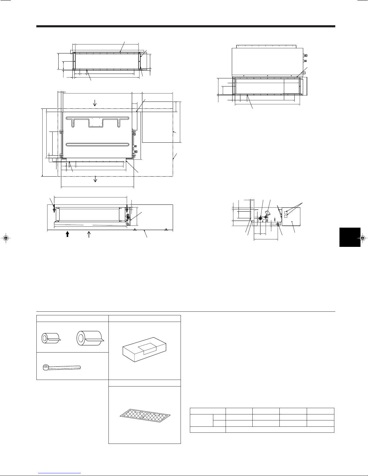
■ SEZ-KA35/KA50/KA60/KA71VA
Air inlet (rear side) dimensions
24-ø2.9 holes
9×2-ø2.9 holes
20 or more
A
Air inlet (bottom side) dimensions
(mm)
PLATE (A)
24-ø2.9 holes
3.1. Indoor unit (Fig. 3-1)
1 Air inlet (rear side) *Select the either back side or bottom side
2 Electrical parts box
3 Suspension bolt pitch
5 Access door
6 Service space (It is necessary to maintain a working service area from the ceiling.)
7 Air inlet (bottom side) *Select the either back side or bottom side
8 Suspension bolt M10 or 3/8 (procure locally)
9 Air outlet duct flange
0 Air outlet
A Refrigerant pipe (gas)
AB
1
2
Fig. 3-2
3
C
4
2×2-ø2.9 holes
Fig. 3-1
B Refrigerant pipe (liquid)
C Wiring entry
D Terminal block
E Drain plug R1
F Air outlet duct flange
G In case of bottom side suction, mount the PLATE (A) on the rear side.
H After installation, remove the transportation suppor t PLATE (B).
I PLATE (B) × 2
J Inlet size
3.2. Checking the indoor unit accessories (Fig. 3-2)
Check that the indoor unit is equipped with the following parts and accessories:
A Refrigerant pipe parts
1 Pipe cover (for refrigerant piping joint)
Small diameter × 1
Large diameter × 1
2 Bands for temporary tightening of pipe cover × 4
B Remote controller parts
3 Parts contained in the cardboard box × 1
Check the contents and read the explanations provided.
C Air filter parts
4 Parts contained in the bag × 1
Check the contents and read the explanations provided.
Refrigerant and drainage pipe sizes
Model SEZ-KA35VA SEZ-KA50VA SEZ-KA60VA SEZ-KA71VA
Refrigerant Liquid
pipe Gas
Drainage pipe Hard PVC pipe : OD ø26 (1")
OD ø6.35 (1/4") OD ø6.35 (1/4") OD ø6.35 (1/4") OD ø9.52 (3/8")
OD ø9.52(3/8") OD ø12.7 (1/2") OD ø15.88 (5/8") OD ø15.88 (5/8")
3
4. Indoor unit installation
G
E
F
ab
b
ce
d
B
A
A
A
B
C
D
350
1070
SEZ-KA35:ø9.52
SEZ-KA50:ø12.7
SEZ-KA60:ø15.88
SEZ-KA71:ø15.88
SEZ-KA35:ø6.35
SEZ-KA50:ø6.35
SEZ-KA60:ø6.35
SEZ-KA71:ø9.52
1
2
Fig. 4-1
Fig. 4-2
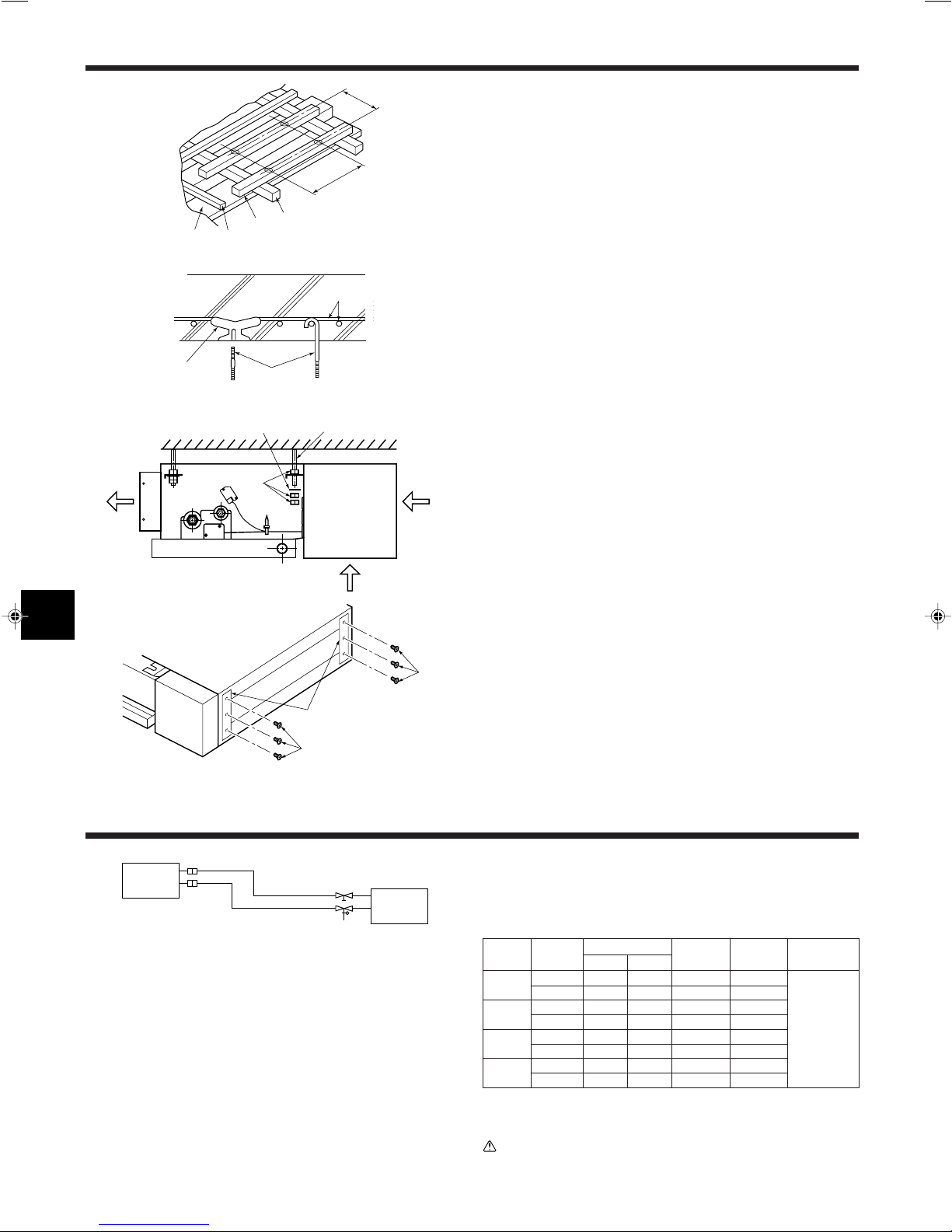
4.1. Suspension Structure (Give site of suspension
strong structure.)
4.1.1. Wooden structure (Fig. 4-1)
• Select tie beam (one-story houses) or second-floor girder (two-story houses) as
reinforcement member.
• Use sturdy beams of at least 6 cm square for beam pitch of 90 cm or less or of at
least 9 cm square for beam pitch of 90-180 cm.
A Ceiling
B Rafter
C Beam
D Roof beam
4.1.2. Ferroconcrete structures (Fig. 4-2)
Secure the suspension bolts using the method shown, or use steel or wooden hangers, etc. to install the suspension bolts.
E Use inserts rated at 100-150 kg each (procure locally)
F Suspension bolts M10 (3/8") (procure locally)
G Steel reinforcing rod
4.1.3. Installing the suspension bolts
• Check the pitch of the suspension bolts.
• Use the ø10 (3/8") suspension bolts (×4, procure locally).
• Adhere strictly to the length of the suspension bolts.
4.2. Suspending the unit (Fig. 4-3)
Direct suspension method:
Raise the unit and line it up with the suspension bolts, then secure it using both
nuts.
a Air outlet
b Air intake (selecting the either back side or bottom side.)
c Washer (procure locally)
d Nuts (procure locally)
e Suspension bolts (procure locally)
Fig. 4-3
Fig. 4-4
5. Refrigerant piping work
Fig. 5-1
1 Indoor unit
2 Outdoor unit
4.3. Transportation support removal (Fig. 4-4)
After installation, completely remove the transportation support because this part
should only be used during transportation.
A 3 screws
B Transportation support
5.1. Refrigerant pipe (Fig. 5-1)
Piping preparation
• Refrigerant pipes of 3, 5, 7, 10 and 15 m are available as optional items.
(1) Table below shows the specifications of pipes commercially available.
Model
SEZKA35VA
SEZKA50VA
SEZKA60VA
SEZKA71VA
Pipe
For liquid
For gas
For liquid
For gas
For liquid
For gas
For liquid
For gas
Outside diameter
mm inch
6.35 1/4
9.52 3/8
6.35 1/4
12.7 1/2
6.35 1/4
15.88 5/8
9.52 3/8
15.88 5/8
Min. wall
thickness
0.8 mm
0.8 mm
0.8 mm
0.8 mm
0.8 mm
1.0 mm
0.8 mm
1.0 mm
Insulation
thickness
8 mm
8 mm
8 mm
8 mm
8 mm
8 mm
8 mm
8 mm
Insulation
material
Heat resisting
foam plastic
0.045 specific
gravity
4
(2) Ensure that the 2 refrigerant pipes are well insulated to prevent condensation.
(3) Refrigerant pipe bending radius must be 10 cm or more.
Caution:
Using careful insulation of specified thickness. Excessive thickness prevents
storage behind the indoor unit and smaller thickness causes dew drippage.
 Loading...