

Mitsubishi SEH-1.6AR.TH, SEH-2.5AR.TH, SEH-2AR.TH, SUH-1.6VR.TH, SUH-2VR.TH Service Manual
...Page 1
TECHNICAL & SERVICE MANUAL
SPLIT-TYPE, HEAT PUMP AIR CONDITIONERS
CONTENTS
1. PART NAMES AND FUNCTIONS ········2
2. SPECIFICATIONS·································4
3. OUTLINES AND DIMENSIONS············6
4. WIRING DIAGRAM·······························9
5.
REFRIGERANT SYSTEM DIAGRAM
······12
6. DATA ···················································16
7. MICROPROCESSOR CONTROL·······20
8. TROUBLESHOOTING························27
9. DISASSEMBLY PROCEDURE···········35
10. PARTS LIST········································42
11. OPTIONAL PARTS ·····························48
<Indoor unit>
SEH-1.6AR.TH
SEH-2AR.TH
SEH-2.5AR.TH
No. OC165
[Models]
INDOOR UNIT
The Slim Line.
From Mitsubishi Electric.
REMOTE CONTROLLER
SUH-1.6VR.TH
SUH-2VR.TH
SUH-2.5VR.TH
<Outdoor unit>
MITSUBISHI ELECTRIC
12
11
10
9
8
7
6
5
4
3
2
1
29
28
27
26
25
24
23
22
21
20
19
18
TIMER TEMP
TIMER/TEMP.
UP
DOWN
POWER
COOL
ON/OFF
MODE
SELECT
FAN
SPEED
TIMER
MODE
DRY
HEAT
HIGH
LOW
AUTO
STOP
START
g
OUTDOOR UNIT
Ceiling Concealed
Series SEH
Page 2
2
1
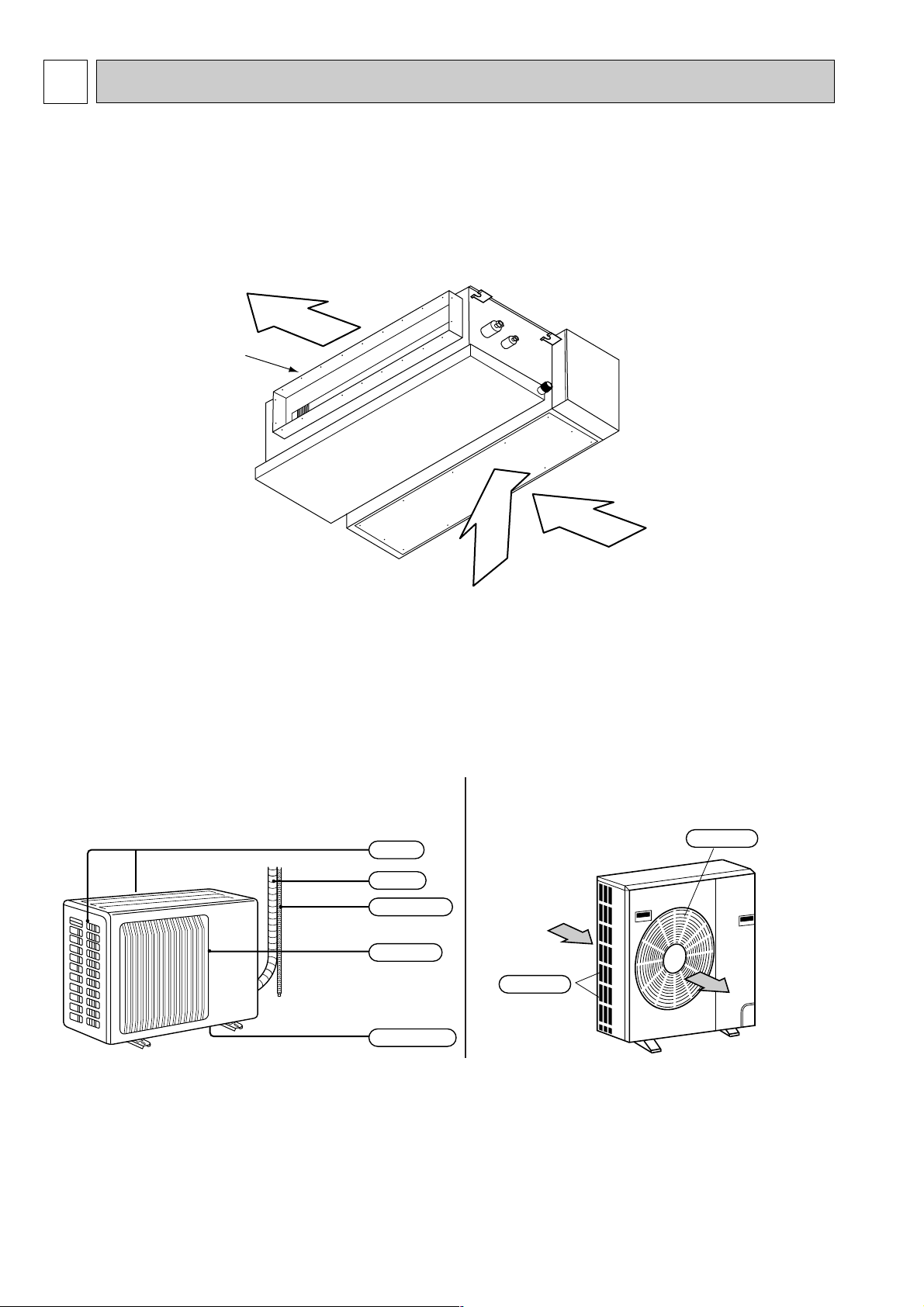
PART NAMES AND FUNCTIONS
● Indoor Unit
SEH-1.6AR.TH
SEH-2AR.TH
SEH-2.5AR.TH
Air outlet duct flange
Air outlet
Air inlet
(Selecting the either back side or bottom side)
SUH-1.6VR.TH
SUH-2VR.TH
Air inlet
Air outlet
Drain outlet
Piping
Drain hose
SUH-2.5VR.TH
Air inlet
Air outlet
● Outdoor Unit
Page 3
3
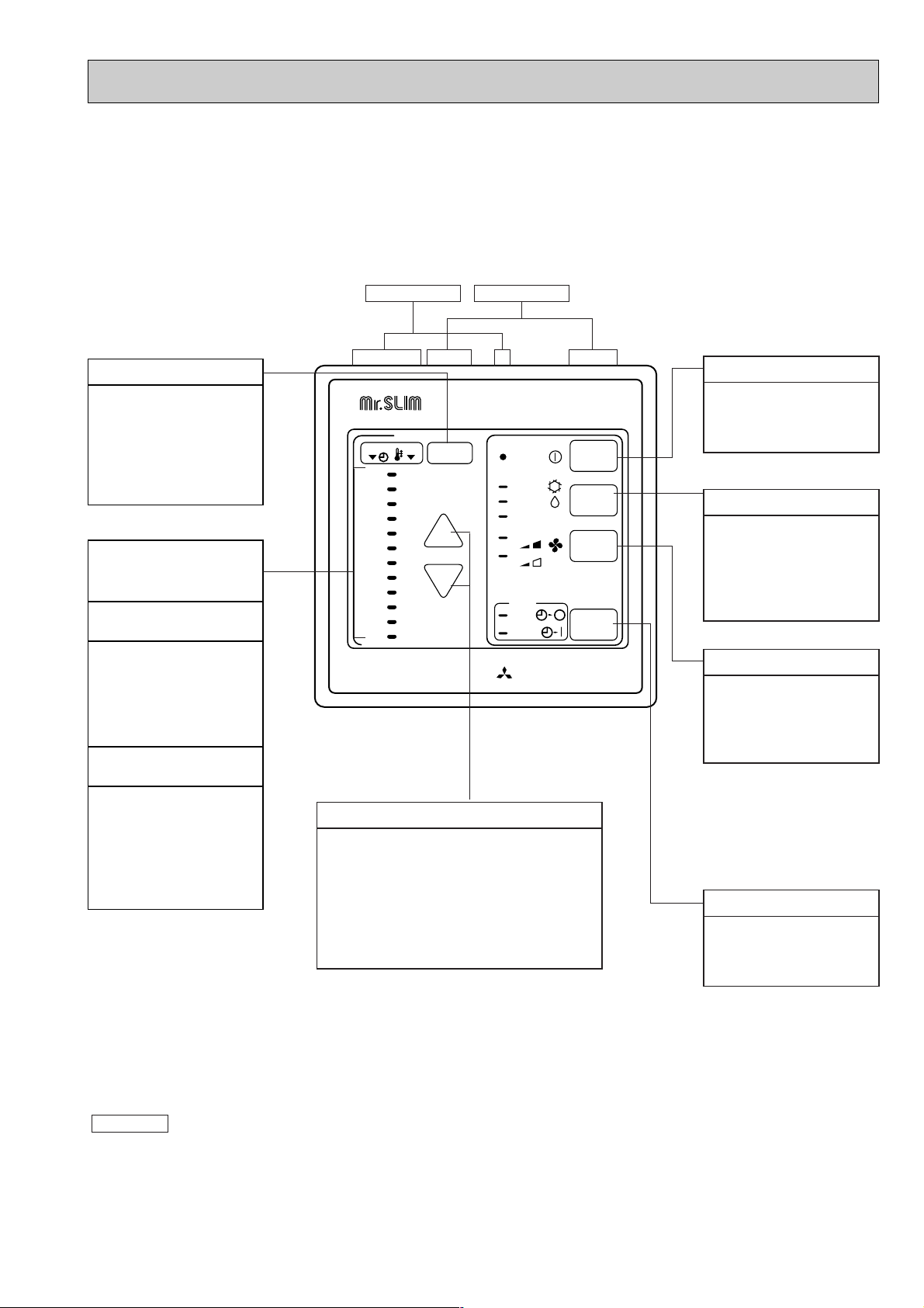
● Remote controller
SEH-1.6AR.TH
SEH-2AR.TH
SEH-2.5AR.TH
MITSUBISHI ELECTRIC
12
11
10
9
8
7
6
5
4
3
2
1
29
28
27
26
25
24
23
22
21
20
19
18
TIMER TEMP
TIMER/TEMP.
UP
DOWN
POWER
COOL
ON/OFF
MODE
SELECT
FAN
SPEED
TIMER
MODE
DRY
HEAT
HIGH
LOW
AUTO
STOP
START
g
TIMER / TEMP.
This button is used to
change between display of
room temperature and
display of remaining timer
during "AUTO STOP"
operation. Green lamps
light in selected display
Remaining timer time
display
Lamps display
remaining timer time
or room temperature.
Lamps indicate time
remaining until timer stops
timed operation. Green
lamps corresponding to
remaining number of hours
light.
Room Temperature
display
Lamps display temperature
settings and actual room
temperatures.
● Temperature settings;
Green lamps light.
● Temperature in room;
Green lamps flash.
(Example display readings are for explanations
only ; autual display readings will differ.)
This button is used to
change between low and
high fan speeds. One of
two green lamps lights to
indicate fan speed in effect.
MODE SELECT button
This button is used to
change between cooling,
heating and DRY operation
modes. One of three green
lamps lights to indicate
mode in effect.
ON / OFF button
Pushing button starts
operation. Pushing again
stops operation. Green
lamp remains lit during
UP and DOWN buttons
● Temperature control (While "TEMP" green
lamps is lit.)
Use UP and DOWN buttons to set disired
temperature between 18 and 29°C.
● Timed operation (While green "TIMER"
lamp is lit.)
Use UP and DOWN buttons to set timed
operation between one and twelve hours.
TIMER MODE button
Used for selecting timed
starting or stopping. Green
lamps lights to indicate
timer mode selected.
● Pushing UP and Down buttons together for more than two seconds will initiate "trial run" or "inspection" mode. Avoid pushing
these buttons simultaneously during normal operation. Push ON / OFF button to cancel trial run or inspection mode if initiated
by accident.
● All green lamps turn off when air conditioner is stopped.
● Avoid operation of buttons with fingernails or other sharp objects. Sharp objects may scratch operating panel.
Attention :
Settings remain in effect until changed. Air conditioner
can be operated by simply pushing ON /OFF button
once settings have been made.
FAN SPEED button
Display Panel Operating Panel
Page 4
4
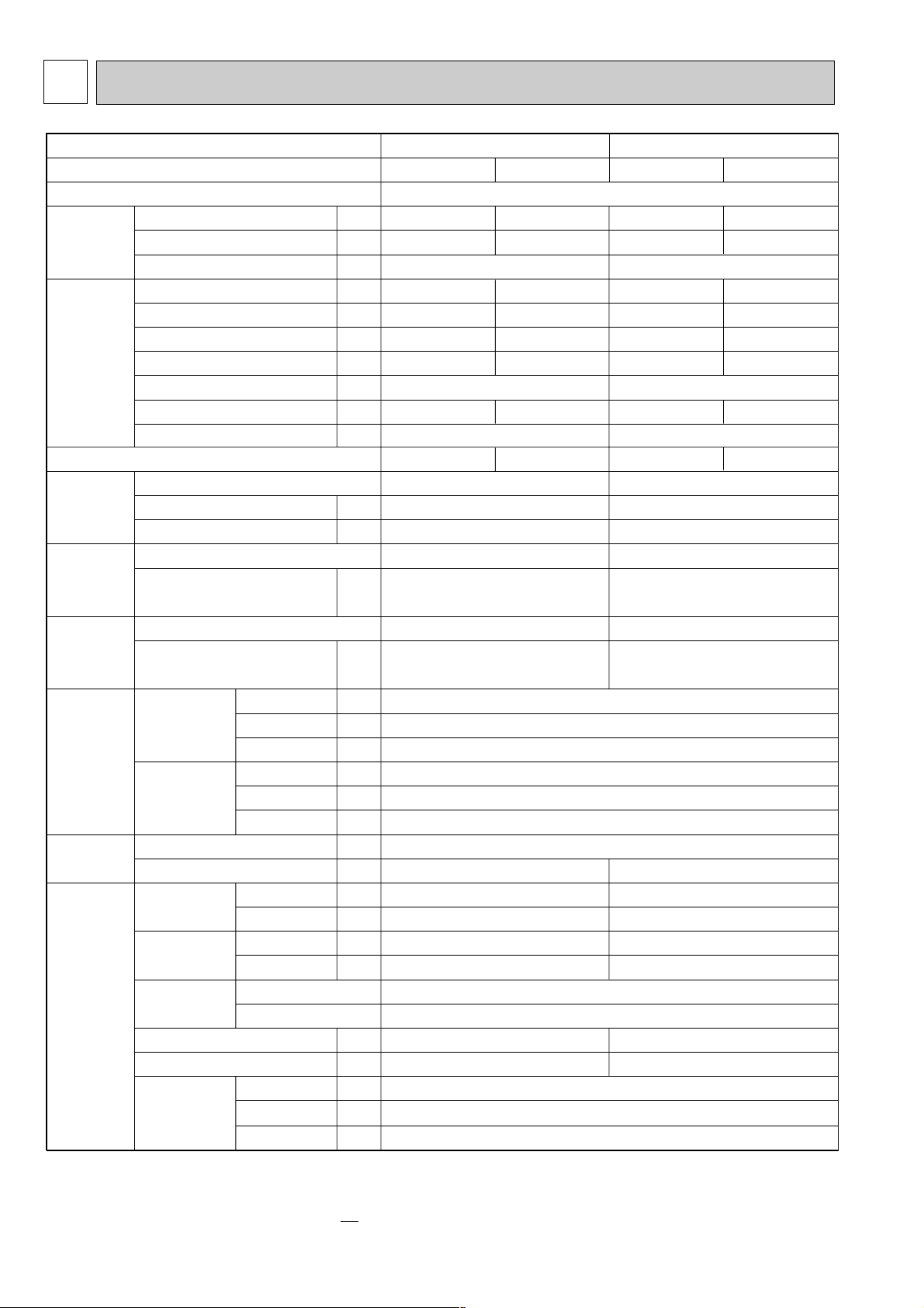
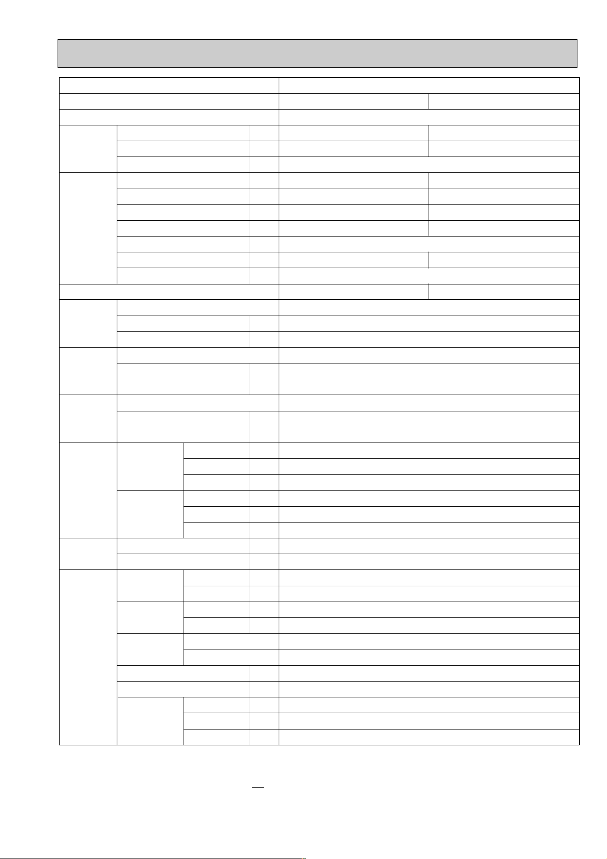
Model
Function
Power supply
Capacity
Dehumidification
Air flow
Running current
Power input
Auxiliary heater
Power factor
Starting current
Compressor motor current
Fan motor current
kW
R/h
K/h
A
W
A(kW)
%
A
A
A
W
"
"
"
mm
mm
mm
mm
mm
mm
kg
kg
dB
dB
rpm
rpm
kg
R
k"
k"
k"
Capacity
Electrical
data
Coefficient of performance(C.O.P)
Compressor
Indoor
fan motor
Outdoor
fan motor
Dimensions
Indoor unit
Indoor unit
Width
Height
Depth
Width
Height
Depth
Indoor unit
Outdoor unit
Indoor unit
Outdoor unit
Indoor unit
Outdoor unit
RT11(at 25:)
RT12(at 25:)
RT61(at 0:)
Sound level
(Hi)
Fan speed
(Hi)
Fan speed
regulator
Outdoor unit
Outdoor unit
Refrigerant filling capacity(R-22)
Thermistor
Weight
Special
remarks
Model
Output
Winding resistance (at 20:)
Model
Winding resistance (at 20:)
Model
Winding resistance (at 20:)
SEH-1.6AR.TH
Single phase, 220-240V, 50Hz
Cooling
SEH-2AR.TH
3.9-3.9
1.7
7.0-7.3
1460-1590
—
95-90
6.41-6.72
2.67-2.45
Heating
4.1-4.2
—
6.4-6.8
1350-1460
—
95-90
5.81-6.22
3.04-2.88
43
35
50
720-770
780-820
1.65
MS-56 O 0.52
RH-247VHAT
1200
C-R:2.13 C-S:3.91
PK6V19-EC
WHT-BLK :251.4 BLK-BLU :19.9
BLU-YLW :26.5 YLW-BRN :13.2
BRN-RED :50.0
RA6V40-EE
WHT-BLK :130.4
BLK-RED :134.6
59
39
52
810-850
810-845
1.8
MS-32(N-1) O 1.2
1100
270
700
850
605
290
35
3
1
10
10
33.18
780
Cooling
5.3-5.4
2.1
10.4-9.9
2270-2330
—
99-97
9.72-9.27
2.33-2.32
Heating
5.7-5.8
—
9.4-9.1
2050-2110
—
99-97
8.72-8.47
2.78-2.75
NH-38VMDT
1700
C-R:1.07 C-S:2.26
PK6V32-EC
WHT-BLK :161.9 BLK-BLU : 50.3
BLU-YLW :18.7 YLW-BRN :8.0
BRN-RED :39.2
RA6V50-OF
WHT-BLK :116.4
BLK-RED :111
1020
35-38 52-58
0.59-0.58 0.68-0.63
Refrigerant oil
SPECIFICATIONS
2
NOTE:Test conditions
Cooling : Indoor DB27°C WB19°C
Outdoor DB35°C WB24°C
Heating : Indoor DB20°C WB
Outdoor DB 7°C WB 6°C
Page 5
5
Model
NOTE:Test conditions
Cooling : Indoor DB27°C WB19°C
Outdoor DB35°C WB24°C
Heating : Indoor DB20°C WB
Outdoor DB 7°C WB 6°C
Function
Power supply
Capacity
Capacity
Electrical
data
Coefficient of performance(C.O.P)
Compressor
Indoor
fan motor
Outdoor
fan motor
Dimensions
Weight
Special
remarks
Dehumidification
Air flow
Running current
Power input
Auxiliary heater
Power factor
Starting current
Compressor motor current
Fan motor current
Model
Output
Winding resistance (at 20:)
Model
Winding resistance (at 20:)
Model
Winding resistance (at 20:)
Width
Indoor unit
Outdoor unit
Indoor unit
Outdoor unit
Sound level
(Hi)
Fan speed
(Hi)
Fan speed
regulator
Refrigerant filling capacity(R-22)
Refrigerant oil
Thermistor
Height
Depth
Width
Height
Depth
Indoor unit
Outdoor unit
Indoor unit
Outdoor unit
Indoor unit
Outdoor unit
RT11(at 25:)
RT12(at 25:)
RT61(at 0:)
kW
R/h
K/h
A
W
A(kW)
%
A
A
A
W
"
"
"
mm
mm
mm
mm
mm
mm
kg
kg
dB
dB
rpm
rpm
kg
R
k"
k"
k"
SEH-2.5AR.TH
Cooling
Single phase, 220-240V, 50Hz
6.6-6.7
3.0
1200
13.5-12.6
2950-2950
—
99-97
59
12.55-11.74
0.95-0.86
2.10-2.14
NH-47VMDT
2200
C-R :0.96 C-S :2.07
PK6V50-EC
WHT-BLK :101.1 BLK-BLU :56.1
BLU-YLW :14.7 YLW-BRN :6.7
BRN-RED :28.2
RA6V85-AA
WHT-BLK :62.7 BLK-YLW :30.2
YLW-RED :62.9
1100
270
700
870
850
295
35
72
43
53
860-890
720-750
3
2
2.4
MS-32(N-1) O 1.2
10
10
33.18
Heating
6.9-7.0
—
12.3-11.8
2680-2750
—
99-97
11.35-10.94
2.57-2.55
Page 6
6
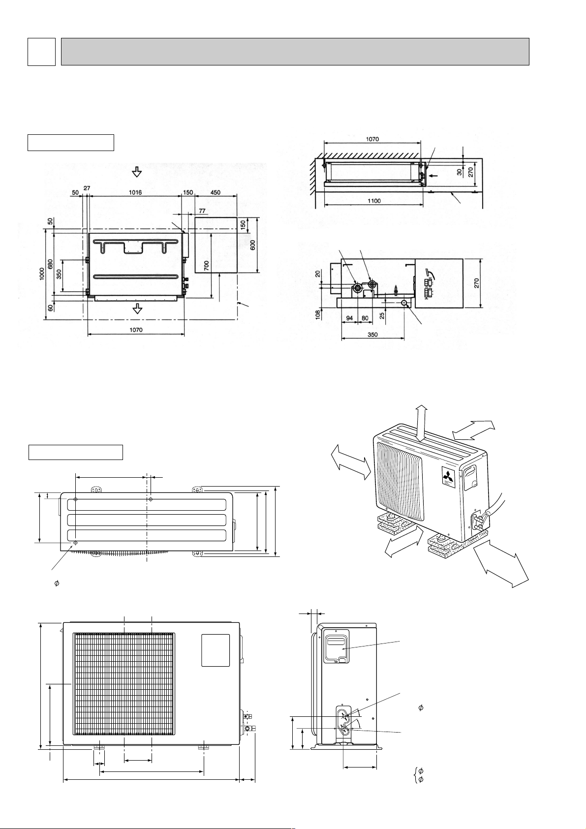
OUTLINES AND DIMENSIONS
3
INDOOR UNIT
SEH-1.6AR.TH
SEH-2AR.TH
SEH-2.5AR.TH
SUH-1.6VR.TH
SUH-2VR.TH
605
29220
50
183
500
161
850
74
30
100
157
35
30
Service panel
Liquid refrigerant
pipe joint
Refrigerant pipe
(flare)
Gas refrigerant
pipe joint
Refrigerant pipe
(flare)
6.35 (SUH-1.6/2VR.TH)
12.7 (SUH-1.6VR.TH)
15.88 (SUH-2VR.TH)
Air inlet
View A
A
Electrical parts box
Suspension
bolt
pitch
Air outlet
Access door
Service space(It is
necessary to maintain
a working service
area from the ceiling.)
20 mm or more
Access door
Electrical
parts
box
Suspension bolt pitch
Suspension bolt pitch
Drain plug R1 male
Refrigerent pipe(liquid)
{6.35(SEH-1.6/2AR.TH)
{9.52(SEH-2.5AR.TH)
Refrigerent pipe(gas)
{12.7(SEH-1.6AR.TH)
{15.88(SEH-2/2.5AR.TH)
Unit : mm
OUTDOOR UNIT
35
248
Drainage
3holes 16.2
350
20
290
310
345
10cm or more
50cm
If the right/left sides or
back side is vacant,the
front has only to be 50cm
unobstructed.
or m
ore
If the front or right/left sides
are vacant, the top has only
to be 10cm
10cm or more
unobstructed.
10cm or more
35cm
or m
ore
Page 7
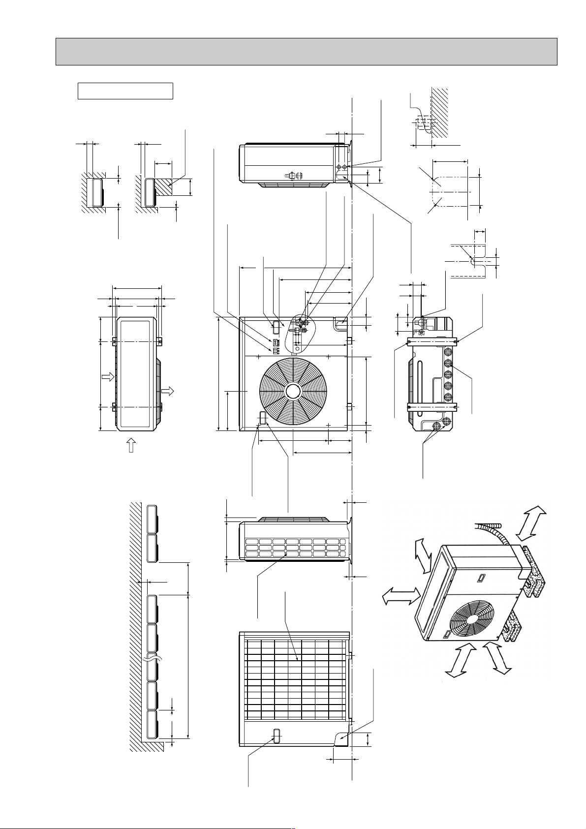
7
SUH-2.5VR.TH
More than 350 mm
More than 10 mm
Open as a rule
More than 500 mm if the
front and both sides are open.
More than 100 mm
More than 200 mm if three
area obstacles to both sides.
Open as a rule
More than 500 mm if the
back both sides and top
are open.
OUTDOOR UNIT
Unit : mm
362
330
150
500
Service space
500
10
39.5 27.5
200
Note:Allow adequate
upper clearance
10
Front opening
10
Outdoor Unit-Necessary surrounding clearance
1715
Air intake
500
4553
Refrigerant-pipe flared
connection [15.88 5/8F
Refrigerant-pipe flared
850
Terminal block for power line
Terminal block for indoor and outdoor unit connection
870
Service panel
Handle for moving
connection [9.52 3/8F
553
352
337
403
Knock out holes for
power line 2-[27
120
60
Knock out hole
for front piping
Knock out hole
(refrigerant,drainage
and wiring)
33
104
R20
0
2
R
for right piping
(refrigerant,drainage
and wiring)
45
42
Bottom
piping hole
25 max.
Standard bolt length
80
65
Front right piping holes-
17
R6
2-U-shaped
notched
holes
detail figures
12
185 185
Air intake
200
The upper side must be open.
Air outlet
1000For 10 units or less
302
724295
Outlet guide
installation hole
Side air intake
Handle for moving
Rear fresh
air intake
441
Drain hole
2-12o23 Oval holes
(standard bolt M10)
179 524
40 60524
Drain hole
33
23
Outdoor Unit-Necessary surrounding clearance
(Concentrated installation)
100 10
Handle
for moving
95
138
Rear piping hole
Page 8
8
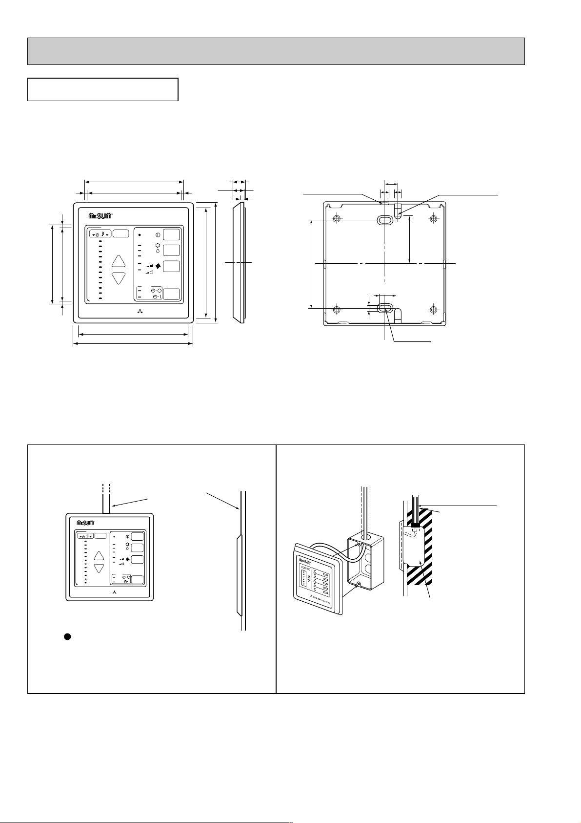
REMOTE CONTROLLER
Remote controller cable installation
MITSUBISHI ELECTRIC
12
11
10
9
8
7
6
5
4
3
2
1
29
28
27
26
25
24
23
22
21
20
19
18
TIMER TEMP
TIMER/TEMP.
UP
DOWN
POWER
COOL
ON/OFF
MODE
SELECT
FAN
SPEED
TIMER
MODE
DRY
HEAT
HIGH
LOW
AUTO
STOP
START
75
69
108
117
108
96.5
12
90.5
11.6
3.6
33
117
33
g
Rear side wiring
arrangememt opening
Upper side wiring
arrangement
opening
Fixing hole
83.5
12
86
4.6
46
9.2
MITSUBISHI ELECTRIC
12
11
10
9
8
7
6
5
4
3
2
1
29
28
27
26
25
24
23
22
21
20
19
18
TIMER TEMP
TIMER/TEMP.
UP
DOWN
POWER
COOL
ON/OFF
MODE
SELECT
FAN
SPEED
TIMER
MODE
DRY
HEAT
HIGH
LOW
AUTO
STOP
START
Exposed remote controller
cable
Cable can be connected only to the
top of the remote controller.
(Right side, left side, and buttom are
not possible.)
g
●For exposed remote controller cable installation
Note : The cable for the remote controller has 10m (39ft) length and 12-core with connectors O.D. 5.8.
●For recessed remote controller cable installation
Unit : mm
Remote controller cable
Conduit tube
(local arrangement)
Switch box
(local arrangement)
Set screw (match with switch box),
local arrangement.
Page 9
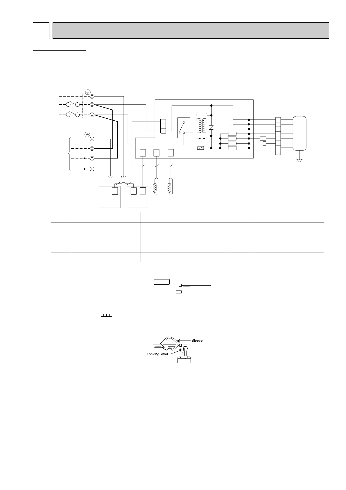
NOTE :1. Since the indoor fan motor (MF) is connected with 50 Hz power, if 60Hz power is used,change the wiring
connection showing fig:*1
Indoor Fan Motor(MF) for 60Hz
2. About the outdoor side electric wiring refer to the outdoor unit electric wiring diagram for servicing.
3. Use copper conductors only. (For field wiring)
4. Symbols below indicate.
/:Terminal block, : Connector
How to remove the terminals shown at ”w” mark.
9
WIRING DIAGRAM
4
TB
CIRCUIT BREAKER
POWER SUPPLY
~/N
220-240V
TB
GRN/YLW
12VDC
3
RED
L
W
W
W
W
W
N
BRN
220-240V~
N
BLU
WHT
GRN/YLW
BLU
TO OUTDOOR
UNIT
CONNECTING
P.C
CONTROLLER
REMOTE
BOARD
CN
113104
CN CN
112
52
2
RT12
1212
CNR
120
CN
120
CN
104B
RT11
TRANS
HIC1
3
CN201
ELECTRONIC CONTROL P.C BOARD
NR11
52C
F11
4
3
2
1
BLU
YLW
YLW
BLU
SR144
LDFH
BLK BLK
8
LDCOM
LDC11
LDC12
LDFL
LDFM
LDFVL
SR142
SR143
SR141
GRN/YLW
WHT
ORN
RED
BRN
BRN
WHT
7
5
6
1
2
3
4
C11
RED
BLU
ORN
MF
50Hz
2
W
SR141
SR144
RT11
TB
TERMINAL BLOCK
RT12 INDOOR COIL
THERMISTOR
HIC1
DC/DC CONVERTER
NR11
MF
52C
F11
SYMBOL
NAME NAME
C11
SYMBOL
FAN MOTOR CAPACITOR
SOLID STATE RELAY
FUSE(3.15A)
COMPRESSOR CONTACTOR
ROOM TEMPERATURE THERMISTOR
VARISTOR
FAN MOTOR
NAMESYMBOL
~
REMOTE
CONTROLLER
INTERFACE
P.C. BOARD
”w” shows the terminals with a lock mechanism,so they cannot be removed when you pull the lead wire.
Be sure to pull the wire by pushing the locking lever (project part) of the terminal with a finger.
1Slide the sleeve.
2Pull the wire while pushing the locking lever.
BLUE
YELLOW
60
50
fig: *1
BLUE
INDOOR UNIT
SEH-1.6/2/2.5AR.TH
Page 10
10
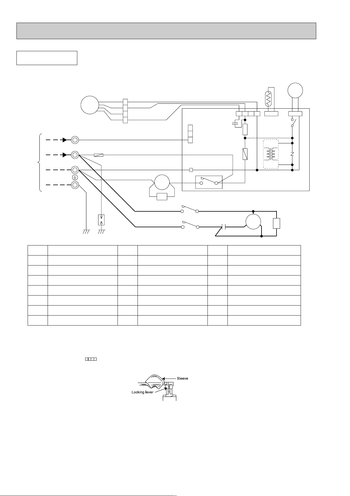
OUTDOOR UNIT
SUH-1.6/2VR.TH
NOTE :1. Use copper conductors only. (For field wiring)
2. Since the indoor and outdoor unit connecting wires have polarity, connect them according to the numbers
(N,2,3 and ;).
3. Symbols below indicate.
/:Terminal block, : Connector
4. ”w” shows the terminals with a lock mechanism,so they cannot be removed when you pull the lead wire.
Be sure to pull the wire by pushing the locking lever (project part) of the terminal with a finger.
1Slide the sleeve.
2Pull the wire while pushing the locking lever.
12VDC
220-240V
TO INDOOR
CONNECTING
UNIT
TB
RT61
21S4
BLK
BLK
4
MF
3
W
2
W
WHT
N
W
GRN/YLW
RED
F
BLU
WHT
DSAR
WHT
ORN
RED
3
2
1
WHT
WHT
RED
BLU
A1
VLT YLW
WHT
BLU
52C1
CR
A2
L1/1 T1/2
CN730
3
2
1
W
TAB20
YLW
52C1
T3/6L3/5
52C
WW
4
3
BLU
W
C1
CN711
C65
WHT
W
RED
BLK
W
123
SR61
F61
C
MC
S
4
CN661
IC881
TRANS
R
BLK
BLK
CN721
X62
NR61
DEICER
P.C. BOARD
WHTWHT
CZ
SYMBOL NAME NAME
C1
COMPRESSOR CAPACITOR
C65
F61 FUSE (2A)
F
FUSE (2A)
MC
COMPRESSOR
<INNER THERMOSTAT>
FAN MOTOR
MF
<INNER THERMOSTAT>
NR61 VARISTOR
SYMBOL
RT61
SR61
TB
X62
21S4
52C
52C1
DEFROST THERMISTOR
SOLID STATE RELAY
TERMINAL BLOCK
REVERSING VALVE RELAY
SOLENOID COIL
CONTACTOR
COMPRESSOR CONTACTOR
NAMESYMBOL
IC881 DC/DC CONVERTER
DSAR
SURGE ABSORBER 1FAN MOTOR CAPACITOR
CR SURGE ABSORBER 2
CZ SURGE ABSORBER 3
Page 11
11
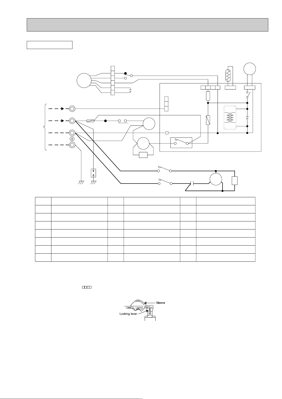
SUH-2.5VR.TH
RED
ORN
WHT
BLK
YLW
12VDC
TB
YLW
2
1
BLK
WHT
ORN
RED
3
4
5
6
MF
X1
BRN
SR61
X62
BLK
CN721
CN730
2
1
3
BLK
21S4
1
5
3
C2
CN711
CN661
123
RT61
4
A2
A1
ORN
WHT
YLWVLT
TB2
CR
WHT
4
52C1
F61
NR61
TRANS
IC881
220-240V~
DSAR
GRN/YLW
RED
W
W
W
W
WW
3
2
N
TO INDOOR
UNIT
CONNECTING
WHT
RED
7
RED
VLT
BLU
26F1
X1
WHT
TAB20
52C
3
YLW
DEICER
P.C. BOARD
BLU
WHTWHT
CZ
T3/6L3/5
BLU
L1/1 T1/2
52C1
WHT
C1
RED
BLK
S
C
R
MC
BLU
8
F
CZ SURGE ABSORBER 3
CR SURGE ABSORBER 2
IC881 DC/DC CONVERTERF61 FUSE (2A)
CONTACTOR
SOLENOID COIL
21S4
X62
MF
FAN MOTOR
<INNER THERMOSTAT>
MC
COMPRESSOR
<INNER THERMOSTAT>
TB,TB2
SR61
RT61
NR61 VARISTOR
F
C2
SYMBOL NAME NAME
C1
DSAR
SYMBOL
COMPRESSOR CAPACITOR
SURGE ABSORBER 1
FAN MOTOR CAPACITOR
FUSE (2A)
TERMINAL BLOCK
52C1
THERMAL REED SWITCH
26F1
X1 FAN MOTOR RELAY
52C
COMPRESSOR CONTACTOR
REVERSING VALVE RELAY
SOLID STATE RELAY
DEFROST THERMISTOR
NAMESYMBOL
NOTE :1. Use copper conductors only. (For field wiring)
2. Since the indoor and outdoor unit connecting wires have polarity, connect them according to the numbers
(N,2,3 and ;).
3. Symbols below indicate.
/:Terminal block, : Connector
4. ”w” shows the terminals with a lock mechanism,so they cannot be removed when you pull the lead wire.
Be sure to pull the wire by pushing the locking lever (project part) of the terminal with a finger.
1Slide the sleeve.
2Pull the wire while pushing the locking lever.
OUTDOOR UNIT
Page 12
12
5
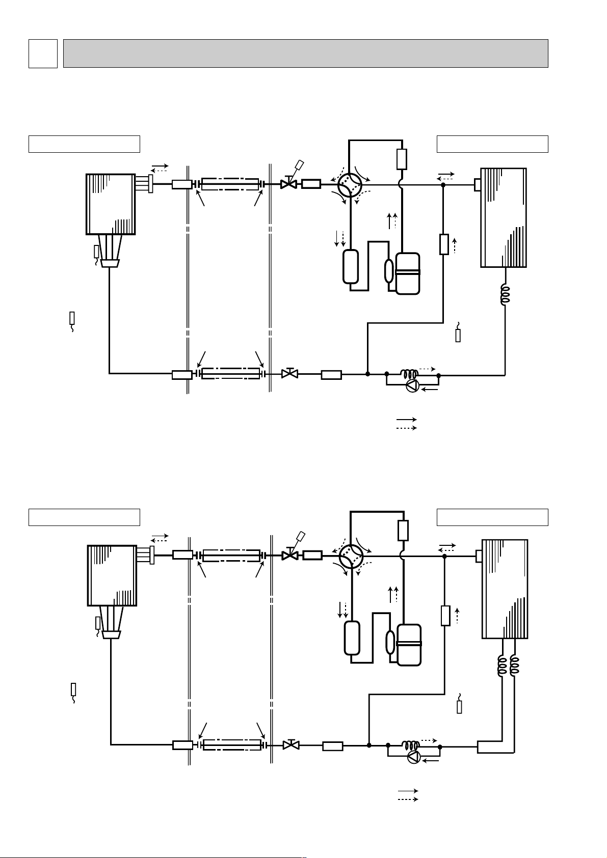
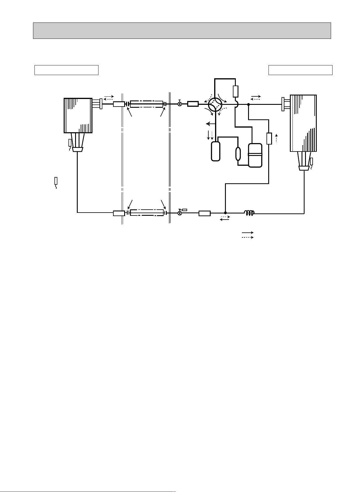
REFRIGERANT SYSTEM DIAGRAM
Indoor
heat
exchanger
Outdoor
heat
exchanger
Distributor
(With strainer)
Flared connection
Room temperature
thermistor
RT11
Indoor coil
thermistor
RT12
Defrost
thermistor
RT61
Flared connection
Stop valve
Stop valve
(with service port)
Strainer
Strainer
Strainer
Capillary tube
({3.0x{1.8xR330)
Capillary
tube
({3.0x{1.6xR550)
Restrictor valve
Refrigerant flow in cooling
Compressor
Accumulator
Strainer 1
valve
Muffler
Refrigerant flow in heating
Refrigerant pipe [12.7
(Option)
(with heat insulator)
Refrigerant pipe
(Option) [6.35
(with heat insulator)
Dis
Pressure
Regulator
Reversing
INDOOR UNIT
SEH-1.6AR.TH
OUTDOOR UNIT
SUH-1.6VR.TH
Indoor
heat
exchanger
Outdoor
heat
exchanger
Distributor
(With strainer)
Flared connection
Room temperature
thermistor
RT11
Indoor coil
thermistor
RT12
Defrost
thermistor
RT61
Flared connection
Stop valve
Stop valve
(with service port)
Strainer
Capillary tube
({4.0X{2.4XR660)
Capillary
tube
({3.0X{1.6XR860)X2
Restrictor valve
Refrigerant flow in cooling
Compressor
Accumulator
Strainer 1
valve
Muffler
Refrigerant flow in heating
Refrigerant pipe [15.88
(Option)
(with heat insulator)
Refrigerant pipe
(Option) [6.35
(with heat insulator)
Dis
Pressure
Regulator
Strainer
Strainer
Reversing
INDOOR UNIT
SEH-2AR.TH
OUTDOOR UNIT
SUH-2VR.TH
Page 13
13
INDOOR UNIT OUTDOOR UNIT
SEH-2.5AR.TH
SUH-2.5VR.TH
Indoor
heat
exchanger
Indoor coil
thermistor
RT12
Room temperature
thermistor
RT11
Strainer
Distributor
(With strainer)
Strainer
Refrigerant pipe [15.88
(Option)
(with heat insulator)
Ball valve
Flared connection
Flared connection
Refrigerant pipe
(Option) [9.52
(with heat insulator)
Muffler
Accumulator
Strainer 3
Ball valve
(with service port)
Reversing
valve
Compressor
Strainer 2
Dis
Pressure
Regulator
Distributor
Capillary tube
({4.0x{2.0xR410)
Refrigerant flow in cooling
Refrigerant flow in heating
Outdoor
heat
exchanger
Defrost
thermistor
RT61
Page 14
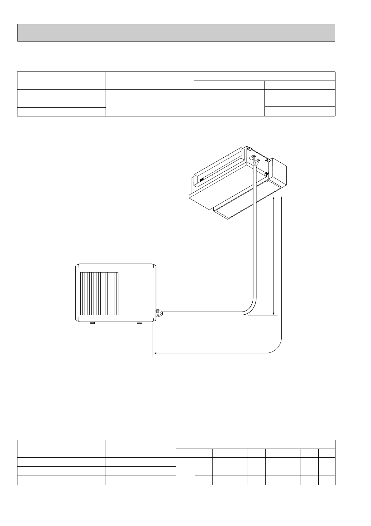
14
Models
A: Refrigerant piping
Max.length
15m(49ft)
Max. Height difference *
7m(23ft)
MAX. REFRIGERANT PIPING LENGTH & MAX. HEIGHT DIFFERENCE
SEH-1.6AR.TH
SEH-2AR.TH
SEH-2.5AR.TH
Length : m(ft)
A
15(49)
Piping size O.D. : mm (in.)
Gas
Liquid
{12.7(1/2)
{6.35(1/4)
{15.88(5/8)
wIt does not matter which unit is higher.
Models
SEH-1.6AR.TH
SEH-2AR.TH
SEH-2.5AR.TH
Outdoor unit:precharged
(up to 7m)
1,650
1,800
Refrigerant piping length (one way)
7m08m509m
100
10m
150
11m
200
12m
250
13m
300
14m
350
15m
400
Calculation : (SEH-1.6/2AR)og=50g/mo(Refrigerant piping length minus 7m)
(SEH-2.5AR)og=65g/mo(Refrigerant piping length minus 7m)
If pipe length exceeds 7m, additional refrigerant (Freon 22) charge is required
ADDITIONAL REFRIGERANT CHARGE (R-22 : g)
{9.52(3/8)
2,400
65
130
195 260
325
390 455 520
Page 15
15
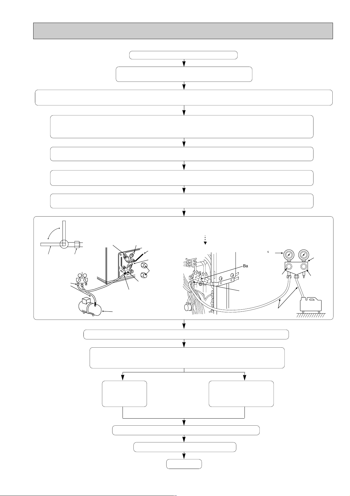
EVACUATION PROCEDURES
Connect the refrigerant pipes (both the liquid and gas
pipes) between the indoor and the outdoor units.
Remove the service port cap of the stop/ball valve on the gas pipe side of the outdoor unit gas pipe.
(The stop/ball valve will not work in its initial state fresh out of the factory (totally closed with cap on).)
Connect the gauge manifold valve and the vacuum pump to the service
port of the stop/ball valve of the outdoor unit. : For SUH-1.6/2VR.TH connect to gas pipe side.
For SUH-2.5VR.TH connect to liquid pipe side.
Run the vacuum pump for more than 15 minutes and at this time confirm that the pressure gauge indicates
-0.1 Mpa (-76 cmHg).
Check the vacuum with the gauge manifold valve, then close the gauge manifold valve, and stop the
vacuum pump.
Leave as it is for one or two minutes. Make sure the pointer of the gauge manifold valve remains in the
same position.
After refrigerant pipes are connected and evacuated, fully open all stop/ball
valves on gas and liquid pipe sides.
Operating without fully opening lowers the performance and causes trouble.
Pipe length :
7m maximum
No gas charge is
needed.
Pipe length
exceeding 7m
Charge the prescribed
amount of gas.
Remove the gauge manifold valve quickly from the service port of the stop/ball valve.
Tighten the cap to the service port to obtain the initial status.
Tighten the cap to the stop/ball valve.
Leak test
Ball valve
(liquid side)
Service port
Valve knob Lo
Valve knob Hi
Charge hose
Vacuum
pump
Manifold
valve
Compound gauge Pressure gauge
-1.01✕10 Pa
(-760mmHg)
Stop valve
Stop valve
Stop valve
Close
Caps
Gauge manifold valve
Gas pipe
Connection
pipe
Open
Vacuum pump
Service port
Hexagonal
wrench
Liquid pipe
Hexagonal
wrench
<SUH-2.5VR.TH>
<SUH-1.6/2VR.TH>
Page 16

16
DATA
6
The standard data contained in these specifications apply only to the operation of the air conditioner under normal condition.
Operating conditions vary according to the areas where these units are installed. The following information has been provided to
clarify the operating characteristics of the air conditioner under the conditions indicated by the performance curve.
(1) GUARANTEED VOLTAGE
Rated voltage : ±10% (198~264V), 50Hz
(2) AIR FLOW
Air flow should be set at MAX.
(3) MAIN READINGS
COOLING
(1) Indoor intake air wet-bulb temperature :
˚CWB
(2) Indoor outlet air wet-bulb temperature :
˚CWB
(3) Outdoor intake air dry-bulb temperature :
˚CDB
(4) Total input : W
Indoor air wet/dry-bulb temperature difference on the side of the chart on page shows the difference between the
indoor intake air wet/dry-bulb temperature and the indoor outlet air wet/dry-bulb temperature for your reference at service.
How to measure the indoor air wet-bulb/dry-bulb temperature difference
1. Attach at least 2 sets of wet-and-dry-bulb thermometers to the indoor air inlet as shown in the figure, and at least 2 sets of wetand-dry-bulb termometers to the indoor air outlet. The thermometers must be attached to the position where air speed is high.
2. Attach at least 2 sets of wet-and-dry-bulb thermometers to the outdoor air inlet.
Cover the thermometers to prevent direct rays of the sun.
3. Check that the air filter is cleaned.
4. Open windows and doors of the room.
5. Press the TEST RUN switch once to start the COOL(HEAT) MODE.
6. When system stabilizes after more than 15 minutes, measure temperature and take an average temperature.
7. 10 minutes later, measure temperature again and check that the temperature does not change.
Air outlet
Air inlet
Wet-and dry-bulb
thermometers
Wet-and dry-bulb
thermometers
BACK VIEW
INDOOR UNIT
OUTDOOR UNIT
HEATING
(1) Indoor intake air dry-bulb temperature :
˚CDB
(2) Indoor outlet air dry-bulb temperature :
˚CDB
(3) Outdoor intake air wet-bulb temperature :
˚CWB
(4) Total input : W
20.6
19.0
17.5
15.9
14.3
12.7
11. 1
8.7
8.0
7.3
6.6
5.9
5.3
9.5
9.4
10.0
8.6
7.8
7.1
6.3
5.6
SEH-2AR.TH
SEH-1.6AR.TH
22.3
22.9
20.6
21.1
18.9
19.4
17.2
17.6
15.4
15.8
13.7
14.1
12.0
12.3
10.3
10.6
9.1
8.3
7.5
6.7
6.0
SEH-2.5AR.TH
SEH-2AR.TH
EH-1.6AR.TH
EH-2.5AR.TH
Page 17

17
Dry Bulb temperature (˚C)
20
25
30
Relative humidity (%)
50
60
70
(4) OUTDOOR LOW PRESSURE AND OUTDOOR UNIT CURRENT
COOL operation
1 Both indoor and outdoor units are under the same temperature/humidity condition.
2 Air flow should be set at MAX.
0.8
0.7
0.6
0.5
0.4
0.3
15 18 20 25 30 32 35(:)
50 60 70 (%)
Ambient temperature (:) / Ambient humidity (%)
Outdoor low pressure
8
7
6
5
4
3
15 18 20 25 30 32 35(:)
50 60 70 (%)
Ambient temperature (:) / Ambient humidity (%)
Outdoor unit current (A)
240V
220V
8
7
5
6
4
3
(MPa•G)
(kgf/F• G)
SEH-1.6AR.TH
3 The unit of pressure has been changed to MPa based on the international system of units(SI unit system).
The converted score against the traditional unit system can be gotten according to the formula below.
1(MPa • G) =10.2(kgf/
f
f
• G)
0.7
0.6
0.5
0.4
0.3
0.2
15 18 20 25 30 32 35(:)
50 60 70 (%)
Ambient temperature (:) / Ambient humidity (%)
Outdoor low pressure
10
9
8
7
6
5
15 18 20 25 30 32 35(:)
50 60 70 (%)
Ambient temperature (:) / Ambient humidity (%)
Outdoor unit current (A)
240V
220V
(MPa•G)
7
6
4
3
2
5
(kgf/F• G)
SEH-2AR.TH
SEH-2.5AR.TH
240V
220V
0.7
0.6
0.5
0.4
0.3
0.2
15 18 20 25 30 32 35(:)
50 60 70 (%)
Ambient temperature (:) / Ambient humidity (%)
Outdoor low pressure
13
12
11
10
9
8
7
15 18 20 25 30 32 35(:)
50 60 70 (%)
Ambient temperature (:) / Ambient humidity (%)
Outdoor unit current (A)
(MPa•G)
7
6
4
3
2
5
(kgf/F• G)
Page 18

18
10
9
8
7
0 2 5 10 15 20 25(:)
Ambient temperature (:)
Outdoor unit current (A)
240V
220V
240V
220V
13
11
9
7
0 2 5 10 15 20 25(:)
Ambient temperature (:)
Outdoor unit current (A)
SEH-2AR.TH
SEH-2.5AR.TH
8
7
6
5
4
3
0 2 5 10 15 20 25(:)
Ambient temperature (:)
Outdoor unit current (A)
HEAT operation
Condition Indoor : Dry bulb temerature 20.0:
Wet bulb temerature 14.5:
Outdoor : Dry bulb temerature 7,15,20:
Wet bulb temerature 6,12,14.5:
240V
220V
SEH-1.6AR.TH
Page 19

19
(5) INDOOR FAN PERFORMANCE AND CORRECTED AIR FLOW
SEH-1.6AR.TH
80
60
40
20
External static pressure(Pa)
(1Pa = 0.1mmAq)
0
Fan Performance
Recommended range
105 7 15 20 25
Air flow (K/X)
1.1
1.0
0.9
Correction factor
0.8
1.3
1.2
1.1
1.0
Correction factor
0.9
Corrected Air flow
Cooling
1051520
Air flow (K/X)
Heating
Capacity
Input
25
SEH-2AR.TH
80
60
40
20
External static pressure(Pa)
(1Pa = 0.1mmAq)
0
SEH-2.5AR.TH
80
60
Fan Performance
Recommended range
15510 2025
Air flow (K/X)
Fan Performance
Recommended range
0.8
Corrected Airflow
1.1
1.0
0.9
Correction factor
0.8
1.2
1.1
1.0
0.9
Correction factor
0.8
Corrected Air flow
1.1
1.0
0.9
Correction factor
0.8
5101520
Air flow (K/X)
Cooling
510152025
Air flow (K/X)
Heating
510152025
Air flow (K/X)
Cooling
10 15 20 25 30
Air flow (K/X)
25
Capacity
Input
Capacity
Input
40
20
External static pressure(Pa)
(1Pa = 0.1mmAq)
0
15510 2025
Air flow (K/X)
1.3
1.2
1.1
1.0
Correction factor
0.9
Heating
10 15 20 25 30
Air flow (K/X)
Page 20

20
MICROPROCESSOR CONTROL
7
1. COOL operation
(1) Compressor control
1 3-minute time delay
To prevent overload, the compressor will not start within 3 minutes after stop.
2 The compressor runs when the room temperature is higher than the set temperature.
The compressor stops when the room temperature is equal to or lower than the set temperature.
3 The compressor stops in check mode.
(2) Indoor fan control
Indoor fan speed LOW/HIGH depends on the remote controller setting.
(3) Outdoor fan control
POWER ON/OFF with the compressor.
(4) Coil frost prevention
1 Temperature control
When the indoor coil thermistor RT12 reads -1°C or below, the coil frost prevention mode starts immediately.
However the coil frost prevention will not work for 5 minutes after the compressor starts.
During the coil frost prevention compressor stops and the indoor fan operates at the set speed for 5 minutes.
After that, if RT12 still reads or below -1°C, this mode prolonged untill theRT12 reads over -1°C.
After the coil frost prevention stops, units will not enter this mode again at least 5 minutes even RT12 reads -1°C.
2 Time control
When the three conditions below have been satisfied for 1 hour and 45 minutes, compressor stops for 3 minutes.
a. Compressor has been continuously operating.
b. Indoor fan speed is Low.
c. Room temperature is below 26°C.
When compressor stops ,the accumulated time is canceled and when compressor restarts, time counting starts from
the beginning.
Time counting also stops temporarily when the indoor fan speed becomes High or the room temperature exceeds 26°C.
However, when two of the above conditions (b.And c.) are satisfied again time accumulation is resumed.
<How to operate>
1 Press POWER ON / OFF button.
2 Press MODE SELECT button to set operation mode to COOL.
3 Check lamp is ON and set desired temperature with UP or DOWN but-
ton.
NOTES : 1. When lamp is ON, press TIMER/TEMP button to change the
display to temperature mode.
2. Set temperature changes by 1°C in the range 18 ~ 29°C each time UP
or DOWN button is pressed.
3. The lighting lamp shows the set temperature, and the flashing lamp
shows the room temperature.
When the room temperature is equal to the set temperature, the lamp
keeps lighting, 0.5 seconds brightly and 0.5 seconds faintly.
TIMER
<COOL operation time chart>
W1 Even if the room temperature rise above the set temperature during this period, the compressor will not start until this
period has ended.
MITSUBISHI ELECTRIC
12
11
10
9
8
7
6
5
4
3
2
1
29
28
27
26
25
24
23
22
21
20
19
18
TIMER TEMP
TIMER/TEMP.
UP
DOWN
POWER
COOL
ON/OFF
MODE
SELECT
FAN
SPEED
TIMER
MODE
DRY
HEAT
HIGH
LOW
AUTO
STOP
START
g
TEMP
Thermostat
Indoor fan
Operation starts by
POWER button
ON.
ON
OFF
ON
OFF
Room temperature
becomes equal to
set temperature.
Room temperature
rises above set
temperature.
LOW or HIGHLOW or HIGH
Operation stops by
POWER button
OFF.
Compressor
Outdoor fan
ON
OFF
}
MIN. 3 minutes 1
Page 21

21
2. DRY operation
<How to operate>
1 Press POWER ON / OFF button.
2 Press MODE SELECT button to set operation mode to DRY.
3 Check lamp is ON and set desired temperature with UP or DOWN but-
ton.
NOTES : 1. When lamp is ON, press TIMER/TEMP button to change the
display to temperature mode.
2. Unable to set temperature. POWER ON/OFF are operated by
microprocessor control automatically.
3. The flashing lamp shows the room temperature.
TIMER
<DRY operation time chart> In case of the room temperature of 23: and above.
Thermostat
Indoor fan
Outdoor fan
compressor
1st ON
8min.
1min
.
4min.
3min.
ON
OFF
OFF
OFF
OFF
OFF
OFF
OFF
OFF
ON
ON
ON
ON
ON
ON
(1) Setting temperature
Follow the right chart with according to the initial room temperature. When
the room temperature is 13: or under, dry operation does not work.
(2) ON/OFF control
When the room temperature is 23°C or over:
Compressor operates by temperature control and time control.
1 Set temperature is controlled to fall 2°C above from initial set temperature.
2 When the thermostat is ON, the compressor repeats 8 minutes ON and 3 minutes OFF.
When the thermostat is OFF, the compressor repeats 4 minutes OFF and 1 minute ON.
Indoor fan and outdoor fan operate in the same cycle as the compressor.
When the room temperature is under 23°C.
When the thermostat is ON, the compressor repeats 2 minutes ON and 3 minutes OFF.
When the thermostat is OFF, the compressor repeats 4 minutes OFF and 1 minute ON.
(3) Coil frost prevention
The operation is same as that of coil frost prevention during COOL mode.
However the indoor fan speed becomes the set speed or Low.
TIMER TEMP
12
11
10
9
8
7
6
5
4
3
2
1
29
28
27
26
25
24
23
22
21
20
19
18
TIMER/TEMP.
UP
DOWN
POWER
ON/OFF
COOL
MODE
DRY
SELECT
HEAT
g
HIGH
FAN
SPEED
LOW
AUTO
STOP
TIMER
MODE
START
MITSUBISHI ELECTRIC
TEMP
Page 22

22
3. HEAT operation
<How to operate>
1 Press POWER ON / OFF button.
2 Press MODE SELECT button to set operation mode to HEAT.
3 Check lamp is ON and set desired temperature with UP or DOWN but-
ton.
NOTES : 1. When lamp is ON, press TIMER/TEMP button to change the
display to temperature mode.
2. Set temperature changes by 1°C in the range 18 ~ 29°C each time UP
or DOWN button is pressed.
3. The lighting lamp shows the set temperature, and the flashing lamp
shows the room temperature.
When the room temperature is equal to the set temperature, the lamp
keeps lighting, 0.5 seconds brightly and 0.5 seconds faintly.
TIMER
(1) Compressor control
1 3minute time delay
To prevent overload, the compressor will not start within 3minutes after stop.
2 The compressor runs when the room temperature is higher than the set temperature.
The compressor stops when the room temperature is equal to or higher than the set temperature.
w 4degrees up control
During heat operation, lower the room temperature for 4degrees more than thermistor value.
3 The compressor stops in check mode.
4 Follow the item (5) during defrosting.
<HEAT operation time chart>
Minimum 3 minutes w1
ON
Thermostat
Indoor fan
Compressor
Outdoor fan
ON
LOW or HIGHLOW LOW LOW or HIGH VLo
OFF
OFF
ON
OFF
Operation starts by
POWER button
ON.
Operation stops by
POWER button
OFF.
Room temperature
becomes equal to
set temperature.
Room temperature
falls below set temperature.
}
w1 Even if the room temperature falls below the set temperature during this period, the compressor will not start until this period has ended.
TIMER TEMP
TIMER/TEMP.
29
12
28
11
27
10
26
9
25
8
24
7
23
6
DOWN
22
5
21
4
20
3
19
2
18
1
POWER
ON/OFF
COOL
MODE
DRY
SELECT
HEAT
UP
g
HIGH
FAN
SPEED
LOW
AUTO
STOP
TIMER
MODE
START
MITSUBISHI ELECTRIC
TEMP
Page 23

23
(2) Indoor fan control
1 Cold air prevention control
The fan runs at set speed when the indoor coil thermistor RT12 temperature exceeds 22°C. The fan operates at VLo
when the temperature is below 18°C. But the fan stops when the indoor fan operates at VLo and the room temperature
is 15°C or less. Released
Cold Air Prevention
NOTE : At initial in hysteresis this control works.
2 New warm air control.
When compressor starts in heating operation or after defrosting, the fan changes the speed with dependance on the
indoor coil thermistor RT12 temperature to blow out warm air.
After releasing of cold air prevention, when the indoor coil temperature is 37°C or above, the fan speed shifts to the set
speed, and when the fan speed is changed by the remote controller, the fan speed is the set speed.
When the indoor coil temperature is less than 37°C, the fan speed is controlled by time as below.
<Time condition> <Indoor fan speed>
less than 2 minutes························Low
2 minutes or more··························High
The upper limit of the fan speed is the set speed.
If the thermostat turns off, this operation changes to flow soft control.
3 Flow soft control
After the thermostat turns off, the indoor fan operates at VLo.
NOTE : When the thermostat turns on, the fan operates at the set speed. Due to the cold air prevention control, the fan
does not start until the indoor coil thermistor RT12 reads 22°C or more.
4 Follow the item (5) during defrosting.
(3) Outdoor fan control
POWER ON/OFF with the compressor. However during defrosting, follow the item (5).
(4) Reversing valve
18°C
22°C
Heating · · · · · ON
Cooling · · · · · OFF
Dry · · · · · · · · OFF
NOTE: The Reversing valve reverses for 5 seconds right before start-up of the compressor.
ON
OFF
ON
OFF
ON
OFF
Compressor
Reversing valve
Outdoor fan
(COOL / DRY)
(HEAT)
5 sec.
5 sec.
Page 24

24
(5) Defrosting
Defrosting of outdoor heat exchanger is controlled by deicer P.C. board, with detection by the defrost thermistor RT61.
1Defrost starting conditions
When all conditions of a),b) are satisfied, the defrosting operation starts.
a) Under the heat operation, the compressor cumulative operation time exceeds 40 minutes without the detrosting
operation working.
b) The defrost thermistor RT61 reads - 3°C or less.
2Defrost terminating conditions
When the condition d) or e) is satisfied, the defrosting operation stops.
d) The defrost thermistor RT61 reads 3.1°C or more.
e) The defrosting time exceeds 10 minutes.
NOTE w When the indoor coil thermistor reads above 18°C, indoor fan operates at VLo for 30 seconds.
w When the indoor coil thermistor reads 18°C or less, the indoor fan stops.
<Defrosting time chart>
Defrost thermistor
3.1: or more
-3: or less
Outdoor 52C relay
(Compressor)
X62
(Reversing valve)
SR61
Outdoor fan
Defrost
counter
Indoor fan
ON
OFF
ON
OFF
ON
OFF
ON
OFF
ON
OFF
Max 10 min.
30 sec.
15 sec.
30 sec.
15 sec.
VLo
w
RT61
Page 25

25
4. TIMER operation
<Timer function>
AUTO STOP ·········Air conditioner stops after the set time lapses.
AUTO START ········Air conditioner starts after the set time lapses.
<How to operate
●
AUTO STOP timer>
1 While lamp is lighting, press TIMER MODE button.
and lamps turn ON.
2 Set the time for the AUTO STOP timer with the UP or DOWN button.
NOTE : The time setting is in 1 hour units up to 12 hours.
3 With the lapse of time, the timer lamps turn OFF one by one, showing the
remaining time.
4 To cancel the AUTO STOP timer and continue operation, press the TIMER MODE
button.
To cancel the AUTO STOP timer and stop operation, press the POWER ON/OFF
button.
<How to operate AUTO START timer>
1 While lamp is OFF, press TIMER MODE button.
and lamps turn ON.
2 Set the time for the AUTO START timer with the UP or DOWN button.
NOTE : The time setting is in 1 hour units up to 12 hours.
3 With the lapse of time, the timer lamps turn OFF one by one, showing the
remaining time.
4 To cancel the AUTO START timer and keep the unit OFF, press the TIMER MODE
button.
To cancel the AUTO START timer and start operation, press the POWER ON /
OFF button.
TIMER
POWER
● POWER
5. TEST RUN
The unit starts the test run by pressing both the UP and DOWN buttons simultaneously for more than two seconds during
lamp ON or the unit OFF.
● The test run automatically stops in 2 hours.
● Set temperature is not displayed during test run.
●
During the test run, the thermo function are as below.
● Room temperature is displayed by the flashing green lamp when TIME/TEMP button is pressed.
● The test run can be released by pressing the POWER ON / OFF or the TIMER MODE button.
TIMER
Initial 30 minutes
Thermo ON at the all time
Since 30 minutes passed to terminating of the
test run
Thermo ON/OFF as 24: of setting
temperature
TIMER TEMP
TIMER/TEMP.
29
12
28
11
27
10
26
9
25
8
24
7
23
6
22
5
21
4
20
3
19
2
18
1
UP
DOWN
POWER
COOL
DRY
HEAT
HIGH
LOW
AUTO
STOP
START
MITSUBISHI ELECTRIC
ON/OFF
MODE
SELECT
g
FAN
SPEED
TIMER
TIMER
MODE
Page 26

26
6. SERVICE FUNCTION
(1) AUTO RESTART FUNCTION
Operating the J2 Jumper line on the remote control Interface P.C.board of the indoor unit.
The function can set the auto restart function.
J2 = Auto restart wAuto restart setting on the shipping.
No J2 = No auto restart
(2) COMPULSORY DEFROSTING MODE FOR SERVICE
By short circuit of the connector JP607 and R853 on the outdoor deicer P.C. board, defrosting mode can be accomplished
regardless of the defrost interval restriction.
Defrost thermistor RT61 must be below -3:.
(3) DEFROST TERMINATION CHANGE
<JPC> when the JPC wire of the deicer P.C. board is cut, the defrost interval time will be changed.(See page 33.)
<JPE> when the JPE wire of the deicer P.C. board is cut, the defrost temperature will be changed.(See page 33.)
(4) 4degrees up Function
Operating the J3 Jumper line on the remote control Interface P.C.board of the indoor unit.
The function can set the 4degrees up function.(See page 32.) W 4degrees setting on the shipping.
J3 = 4degrees up
NoJ3 = No 4degrees up
Model
Jumper wire Change point
JPC
JPE
Defrost interval time changes from 40 minutes to 15minutes.
Defrost start temperature changes from
-3: to 0:.
Defrost finish temperature changes from
3.1: to 10.1:.
SEH-1.6AR.TH
SEH-2AR.TH
SEH-2.5AR.TH
Page 27

27
TROUBLESHOOTING
8
1. Cautions on troubleshooting
(1) Before troubleshooting, check the followings:
1Check the power supply voltage.
2Check the indoor/outdoor connecting wire for mis-wiring.
(2) Take care the followings during servicing.
1 Before servicing the air conditioner, be sure to first turn off the remote controller to stop the main unit, and then turn
off the breaker.
2 When removing the electronic control P.C. board, hold the edge of the board with care NOT to apply stress on the
components.
3 When connecting or disconnecting the connectors, hold the housing of the connector. DO NOT pull the lead wires.
Page 28

28
2. Self diagnostic function
(1) When trouble occurs during operation, the unit stops and enters the self-diagnotic mode, and displays the trouble
location with the timer lamps on the remote controller. All the other lamps are OFF.
(2) To activate the self-diagnostic function for service, press the UP and DOWN buttons simultaneously for more than two
seconds during operation with lamp ON.
(3) The timer lamps show the latest trouble. Trouble data is memorised unit the next trouble occurs, even when the breaker
turns OFF. To clear the memory, press the UP and DOWN buttons simultaneously for more than two seconds during
the test run.
(4) All buttons except the POWER ON/OFF button are unavailable during the self-diagnostic mode.
(5) To release the self-diagnostic mode, press the POWER ON/OFF button.
TEMP.
12
11
10
9
8
7
6
5
1
2
3
4
(Indicates that the unit is in self-diagnostic mode)
TIMER TEMP.
29 Remote controller interface signal error
28 Mis-wiring or indoor-outdoor signal error
27 Indoor thermistor abnormally
26 Outdoor thermistor abnormally
25
24
23
22
18
19
20
21
Page 29

29
3. Trouble shooting
(1) In case of being indicated irregularity on the self diagnoses
No Phenomenon Cause Countermeasure
29 Remote controller interface
signal error
Mis-wiring of the Interface
P.C.board.
Reinsert the wiring connector of the Interface
P.C.board.
Trouble of the Interface P.C.board.
Exchange the Interface P.C.board.
Trouble of the Indoor P.C.board. Exchange the Indoor P.C.board.
28
Mis-wiring
Wiring between the indoor and
outdoor is coming off.
Check the wiring out between the indoor and
outdoor.
Difference of wiring polarity
between the indoor and outdoor.
Indoor-outdoor
signal error
Trouble of the outdoor deicer
P.C.board.
Check the deicer P.C.board out.
Trouble of the Indoor P.C.board.
Exchange the Indoor P.C.board.
27
Indoor coil thermistor Mis-connecting of the Indoor coil
thermistor.
Reinsert the connector (CN112).
Trouble of the Indoor coil
thermistor.
Room temperature
thermistor
Trouble of the Indoor P.C.board.
Check the resistance value of the thermistor.
Mis-connecting of the room
temperature thermistor.
Exchange the Indoor P.C.board.
Reinsert the connector (CN113).
Trouble of the room temperature
thermistor.
Trouble of the Indoor P.C.board.
Exchange the Indoor P.C.board.
Check the resistance value of the thermistor.
26 Outdoor thermistor
Mis-connecting of the Outdoor
thermistor.
Reinsert the connector (CN661).
Trouble of the Outdoor thermistor.
Trouble of the deicer P.C.board.
Check the resistance value of the thermistor.
Exchange the deicer P.C.board.
Page 30

30
(2) Other case
Phenomenon Cause Countermeasure
Not working of remote
controller switch ON/OFF
Mis-connecting the remote control wiring. Reinsert the connector of remote control wiring.
Mis-connecting the Interface P.C.board.
Reinsert the wiring connector of Indoor P.C.board
and Interface P.C.board.
Short circuit the protecting parts in the
Indoor P.C.board.
Check the varistor(NR11) and fuse(F11) out in the
Indoor P.C.board.
Trouble of the Interface P.C.board.
Check the Interface P.C.board out.
Trouble of the Indoor P.C.board.
Working the Indoor units and
not working the outdoor
units.
Trouble of the remote controller. Exchange the remote controller.
Wiring between the indoor and outdoor is
coming off.
Check the wiring out between the indoor and
outdoor.
Difference of wiring polarity between the
indoor and outdoor.
Check the deicer P.C.board out.
Trouble of the deicer P.C.board.
Not rotating the fan in the
indoor unit.
Trouble of the contactor(52C1).
Trouble of the compressor(MC) and
outdoor fan motor(MF).
Exchange the contactor.
Check the compressor and fan motor out.
Frequency switching connector is coming
off.
Fan motor connector is coming off.
Check the connector out.
Check the frequency (50Hz/60Hz) in the indoor
unit.
Trouble of the Indoor P.C.board. Check the fan motor output of the Indoor
P.C.board.
Trouble of the fan motor.
Check the resistance value between the each tap
of fan motor.
Check the Indoor P.C.board out.
Page 31

31
4. Test point of P.C.board
(1) Indoor electronic control P.C. board
Fan motor power supply 220 - 240V AC
75643218
Lo
60Hz
Hi
Fuse 250V AC 3.15A
Power supply
input 220-240V AC
12V DC
5V DC
+
–
+
–
Time short point
Indoor coil thermistor (RT12)
VLo Lo
50Hz
Room temperature thermistor (RT11)
Indoor coil thermistor (RT12)
Room temperature thermistor (RT11)
40
30
20
Resistance (K')
10
0
0
10 20 30 40 50 60
Temperature ( C)
Page 32

32
(2) Remote controller interface P.C. board
To
Indoor electronic
control P.C.board
To
REMOTE CONTROLLER
– JP15= 0V
+ JP16= 12V DC
+ JP17= 5V DC
AUTO RESTART
FUNCTION
4degrees up
Function
Page 33

Outdoor fan motor
220-240V AC
Solenoid coil
220-240V AC
R601
5~10V DC
+
INPUT
220-240V AC
Defrost thermistor(RT61)
Fuse 2A/250V
Defrost interval
time short pin
}
J9
J8
5V DC
Defrost interval
Defrost termination
temperature change
Jumper wire JPC and JPE
}
52C
12V DC
+
}
12V DC
+
}
}
}
}
}
DEICER P.C. BOARD
+
33
(3) Deicer P.C. board
Page 34

34
Measure the resistance between the terminals with a tester.
(Coil wiring temperature10°C ~ 30°C)
Compressor
Room
temperature
thermistor
5. Trouble criterion of main parts
Part name
Indoor coil
thermistor
Indoor fan
motor
Outdoor fan
motor
Check method and criterion
Measure the resistance with a tester.
(Part temperature 10°C ~ 30°C)
Measure the resistance between the terminals with a tester.
(Coil wiring temperature -10°C ~ 40°C)
Measure the resistance between the terminals with a tester.
(Coil wiring temperature -10°C ~ 40°C)
Figure
C
S
R
BLK
RED
WHT
BLK RED ORNYLW
BLU
BRN
WHT
GRN
YLW
P
Normal
8kΩ ~ 20kΩ
Abnormal
Opened or short-circuited
Normal
1.6VR
1.87~2.30Ω
3.44~4.22Ω
2VR
0.94~1.16Ω
1.99~2.44Ω
C-R
C-S
Normal
Abnormal
Opened or
short-circuited
2AR
WHT-BLK
Normal
Abnormal
Opened or
short-circuited
102 ~ 126Ω
97.9 ~ 120Ω
2VR
WHT-BLK
BLK-RED
1.6VR
115 ~ 141Ω
118 ~ 146Ω
1.6AR
155.5~168.2Ω241.4~261.2Ω
BLK-BLU
48.3~52.3Ω19.0~20.6Ω
BLU-YLW
17.8~19.4Ω25.4~27.5Ω
YLW-BRN
7.6~8.3Ω12.6~13.7Ω
BRN-RED
37.6~40.7Ω47.9~51.9Ω
Abnormal
Opened or
short-circuited
1.6/2VR
BLK
RED ORN
WHT
MAIN
AUX
P
: Inner protector
p
2.5VR
0.84~1.04Ω
1.82~2.24Ω
55.3 ~ 67.7Ω
2.5VR
BLK-YLW
YLW-RED
26.6 ~ 32.6Ω
55.4 ~ 67.9Ω
2.5VR
BLK YLW
RED ORN
WHT
MAIN
AUX.2
AUX.1
P
Defrost
thermistor
(Outdoor)
Measure the resistance with a tester.
(Part temperature - 10°C ~ 40°C)
Normal
5kΩ ~ 60kΩ
Abnormal
Opened or short-circuited
Indoor Unit : SEH-1.6AR.TH SEH-2AR.TH SEH-2.5AR.TH
Outdoor Unit : SUH-1.6VR.TH SUH-2VR.TH SUH-2.5VR.TH
2.5AR
97.0~105Ω
53.8~58.3Ω
14.0~15.3Ω
6.3~6.9Ω
27.0~29.3Ω
Page 35

35
1. Removing the electrical parts
(1) Remove the 2 screws and the electrical parts cover.
(See Photo 1.)
● Indoor controller board
● Transformer
● Run capacitor
● Fuse (3.15A)
● Terminal block
(See Photo 2.)
DISASSEMBLY PROCEDURE9
Indoor Unit : SEH-1.6AR.TH SEH-2AR.TH SEH-2.5AR.TH
OPERATING PROCEDURE PHOTOS
2. Removing the indoor coil thermistor(RT12)
(1) Remove the electrical parts cover.
(See Photo 1.)
(2) Remove the 2 screws and the service panel.
(See Photo 1.)
(3) Remove the thermister (RT12) from the holder.
(See Photo 3.)
(4) Disconnect the connector (CN112) from the indoor
controller board and pull the lead wire of thermistor
(RT12) out.
Drain pan
Electrical parts cover
Service panel
Front panel
Set screws
(for drin pan)
Fuse
Set screws
Terminal block
Transformer
Run capacitor
Thermistor
(RT12)
Photo 2.
Photo 3.
Photo 1.
Page 36

36
3. Removing the room temp. thermistor(RT11)
(1) Remove the electrical parts cover.
(See Photo 1.)
(2) Remove the front panel at fan side.(12 screws)
(See Photo 1.)
(3) Remove the thermister (RT11) from the fan casing.
(See Photo 4.)
(4) Disconnect the connector (CN113)from the indoor
controller board and pull the lead wire of
thermistor (RT11) out.
PHOTOS
OPERATING PROCEDURE
4. Removing the sirocco fan and the fan moter.
(1) Remove the electrical parts cover.
(See Photo 1.)
(2) Remove the front panel at fan side.(12 screws)
(See Photo 1.)
(3) Disconnect the fan motor connector from the indoor
controller board
(See Photo 2.)
(4) Remove the thermistor (RT11) from the fan casing.
(See Photo 4.)
(5) Undo the 4 claws and remove the fan claws.(down side)
<Either left or right>
(See Photo 4.)
(6) Remove the motor bands. (A screw each on left and
right.)
(See Photo 4.)
(7) Disconnect the earth wire.(from the fan motor leg.)
(See Photo 5.)
(8) Remove the fan motor and the sirocco fan by assembly.
(See Photo 5.)
(9) Unscrew the setting screw and remove the sirocco fan.
<Either left or right>
(See Photo 5.)
Set screw
Earth wire
Motor bands
Thermistor
(RT11)
Claws
Screws
Fan casing
Fan motor
Claws
Photo 4.
Photo 5.
Page 37

37
5. Removing the drain pan
(1) Unscrew each set screw on the right and left, and
remove the drain pan pushing it toward the the back.
(See Photo 1.)
PHOTOS
OPERATING PROCEDURE
6. Removing the heat exchanger
(1) Remove the drain pan.
(See Photo 1.)
(2) Remove the Under flange at heat exchanger side.
(16 screws)
(See Photo 6.)
(3) Remove the 4 screws of heat exchanger.( 2 screws
each on left and right)
(See Photo 7.)
(4) Remove the service panel.( 3 screws )
(See Photo 7.)
(5) Put the heat exchanger down to the fan motor and
pull it toward you.
(See Photo 7.)
Screws
Under flange
Screws
(for heat exchanger)
Service panel
Screws
(for service panel)
Heat exchanger
Photo 6.
Photo 7.
Page 38

38
OPERATING PROCEDURE PHOTOS
1. Removing the front panel
(1) Remove the screws of the front panel.
(2) Hold the bottom of the front panel on the both side to
remove the cabinet.
2. Removing the deicer P.C. board
(1) Remove the service panel and the front panel.
(2) Disconnect all the connectors and the terminals on the
deicer P.C. board.
(3) Remove the deicer P.C. board.
Ourtdoor Unit : SUH-1.6VR.TH SUH-2VR.TH
Photo 1
Photo 3
Photo 2
Black lead wire
White lead wire
Screws
Screws
Service
panel
Terminal
block
Screws
Red lead wire
Deicer
P.C. board
Page 39

39
OPERATING PROCEDURE PHOTOS
3. Removing the outdoor fan motor
(1) Remove the front panel. (Refer to 1)
(2) Unconnect the connector remove the clamp of fan motor
lead wire.
(3) Remove the propeller nut and remove the propeller fan.
(4) Remove screws fixing the fan motor.
4. Removing the compressor
(1) Remove the front panel. (Refer to 1)
(2) Remove the soundproof felt.
(3) Remove the terminal cover on the compressor
(4) Remove the electrical assembly.
(Refer to 2)
(5) Release gas from the refrigerant circuit.
(6) Disconnect the welded part of the discharge pipe
(7) Disconnect the welded part of the suction pipe.
(8) Remove nuts fixing the compressor.
(9) Remove the compressor.
Photo 5
Terminal cover
Compressor
Discharge
pipe
Suction
pipe
Compressor nuts
Photo 4
propeller fan
Set screws for
outdoor fan motor
Lead clamps
Outdoor
fan motor
Propeller
fan nut
Set screws for
outdoor fan motor
Page 40

40
OPERATING PROCEDURE PHOTOS
1. Removing the electrical parts
(1)
Remove the 5 screws and the top panel. (3 screws in
front and 2 screws in rear
)
(2)
Remove the screw of the cover panel. To remove the
cover panel, pull it toward you and unhook the catches
from the side panel.
(3)
Remove the screw of the service panel. To remove the
service panel, pull it down toward you and unhook the
catches on the both sides.
2. Removing the fan motor
(1)
Remove the 3 screws of the front panel. Open the
front panel to a 45-degree angle. Then lift it and
unhook the 3 catches to remove.
(2)
Remove the propeller fan nut and the propeller fan.
(3)
Remove the 3 screws and the fan motor.
Disconnect the lead connectors.
Photo 1
Photo 2
Photo 3
Top panel
Service panel
Panel cover
Front panel
Capacitor
Contactor
Terminal blockScrews
Screws
Ourtdoor Unit : SUH-2.5VR.TH
Propeller fan nut
Valve bed
Lead
connectors
Separator support plate
Motor support
Propeller
fan
Page 41

41
OPERATING PROCEDURE PHOTOS
3. Removing the heat exchanger and the compressor
(1)
Remove the rear panel (2 screws in front, 1 screw on
the side, 3 screws in the rear). Remove the valve bed,
and open the rear panel to the rear to remove.
NOTE :
All panels are fixed by catches, and must be removed by
shifting up and down.
(2)
Remove the 4 screws of the right side panel and
remove it.
(3)
Remove the 3 screws of the rear guard and remove it.
(4)
Remove the 4 screws of the separator support plate
and remove it.
(5)
Remove the 2 screws of the motor support and
remove it.
(6)
Remove the 5 screws of the valve bed.
The valve bed is fixed by the catches on the right and
left sides.
Lift it to remove.
(7)
Remove the electrical parts box.
Disconnect the connectors from the high pressure
switch, crank case heater, shell thermo, and fan motor
lead.
(8)
Remove the 2 screws of the separator and remove it.
(9)
Remove the 2 screws of the heat exchanger and
remove it.
Detach the welded point of pipe.
(
10
)
Remove the 3 nuts of the compressor and remove it.
Detach the welded points of the compressor suction
pipe and discharge pipe.
Photo 4
Photo 5
Photo 6
Compressor
Ball valve
Charge plug
Heat exchanger
Accumulator
Screws
Screws
Page 42

42
PARTS LIST10
No.
Parts No.
Parts name
Specification
Remarks
Unit
Amount
Wiring
Diagram
Symbol
Recommended
Q'ty
Q'ty/set
Price
1
2
3
4
5
6
7
8
9
10
11
12
13
14
FRONT PANEL
RIGHT SIDE PANEL
LEFT SIDE PANEL
BASE
FAN MOTOR
FAN MOTOR
FAN MOTOR
SIROCCO FAN
RUBBER MOUNT
INDOOR HEAT EXCHANGER
INDOOR HEAT EXCHANGER
INDOOR HEAT EXCHANGER
DRAIN PAN
RIGHT LEG
LEFT LEG
INDOOR COIL THERMISTOR
ROOM TEMPERARURE THERMISTOR
SEPARATOR ASSY
E07 039 000
E07 051 085
E07 039 086
E07 039 290
E07 039 300
E07 040 300
E07 041 300
E07 039 500
E02 179 505
E07 039 620
E07 040 620
E07 041 620
E07 039 700
E07 039 808
E07 039 809
E07 039 307
E07 039 308
E07 039 293
(Drawing No.)
MF
MF
MF
RT12
RT11
SEH-1.6
SEH-2
AR.TH
SEH-2.5
1
1
1
1
1
2
2
1
1
2
2
1
1
1
1
1
1
1
1
2
2
1
1
2
2
1
1
1
1
1
1
1
1
2
2
1
1
2
2
1
1
1
INDOOR UNIT
STRUCTURAL PARTS
SEH-1.6AR.TH
SEH-2AR.TH
SEH-2.5AR.TH
12
8
9
1
13
6
7
11
3
4
2
5
Part number that are circled is not shown in the illustration.
14
Page 43

43
INDOOR UNIT
ELECTRICAL PARTS
SEH-1.6AR.TH
SEH-2AR.TH
SEH-2.5AR.TH
SEH-1.6 SEH-2 SEH-2.5
AR.TH
No.
Parts No.
Parts name
Specification
3.15A
Remarks
(Drawing No.)
Unit
Amount
Wiring
Diagram
Symbol
Recom-
mended
Q'ty
Q'ty/set
Price
1
2
3
4
5
6
7
8
9
10
11
12
CABLE(FOR BOARD)
REMOTE CONTROLLER CABLE
COMPRESSOR CONTACTOR
TERMINAL BLOCK
TERMINAL BLOCK
FUSE
VARISTOR
REMOTE CONTROLLER
REMOTE CONTROLLER COVER
ELECTRONIC CONTROL P.C. BOARD
ELECTRONIC CONTROL P.C. BOARD
ELECTRONIC CONTROL P.C. BOARD
REMOTE CONTROLLER INTERFACE P.C. BOARD
CONTROLLER COVER
1
1
1
1
1
1
1
1
1
1
1
1
E07 039 087
E07 027 089
E02 138 340
E02 367 377
E02 199 374
E02 127 382
E02 085 385
E07 039 426
E07 027 088
E07 039 450
E07 040 450
E07 041 450
E07 039 454
E07 039 449
52C
TB
TB
F11
NR11
1
1
1
1
1
1
1
1
1
1
1
1
1
1
1
1
1
1
1
1
1
1
1
1
L,N,
3,2,N,
8921 11 10
4
5
3
6
Part number that are circled is not shown in the illustration.
Page 44

44
OUTDOOR UNIT
STRUCTURAL PARTS
SUH-1.6VR.TH
SUH-2VR.TH
2
6
15
10
9
32517 19 18 26 4 24
3252120 1
8
Page 45

45
No.
Parts No.
Parts name
Specification
Remarks
Unit
Amount
Wiring
Diagram
Symbol
Recom-
mended
Q'ty
Q'ty/set
Price
1
2
3
4
5
6
7
8
9
10
11
12
13
14
15
16
17
18
19
20
21
22
23
24
25
26
27
28
29
30
31
32
(Drawing No.)
S-N18EX
S-N11EX
3.0MF-440VAC
50MF-440VAC
35MF-440VAC
3RUBBER
4RUBBER
RH-247VHAT
NH-38VMDT
[3.0O[1.8OR330
[3.0O[1.6OR860
[4.0O[2.4OR660
[3.0O[1.6OR550
MF
MF
RT61
52C1
52C1
C65
C1
C1
TB
F
DSAR
NR61
21S4
21S4
1
1
1
1
1
1
1
1
1
1
1
1
1
1
1
1
1
3
1
1
1
1
1
1
1
1
1
1
1
1
1
1
1
1
1
1
1
1
1
1
1
1
1
1
1
1
1
1
1
1
4
1
1
1
1
1
1
1
1
1
1
2
1
1
1
1
FRONT PANEL
BACK PANEL (OUT)
SERVICE PANEL
BASE
BASE
FAN MOTOR
FAN MOTOR
DEFROST THERMISTOR
COMPRESSOR CONTACTOR
COMPRESSOR CONTACTOR
FAN MOTOR CAPACITOR
COMPRESSOR CAPACITOR
COMPRESSOR CAPACITOR
TERMINAL BLOCK
FUSE (OUT)
FUSE HOLDER
SURGE ABSORBER 1
VARISTOR
DEICER P.C. BOARD
DEICER P.C. BOARD
SOLENOID COIL
SOLENOID COIL
PROPELLER FAN
COMPRESSOR RUBBER MOUNT
COMPRESSOR RUBBER MOUNT
MOTOR SUPPORT
GRILLE (OUT)
OUTDOOR HEAT EXCHANGER
OUTDOOR HEAT EXCHANGER
RESTRICTOR VALVE
RESTRICTOR VALVE
DIS PRESSURE REGULATOR
STOP VALVE (GAS)
STOP VALVE (GAS)
STOP VALVE (LIQUID)
COMPRESSOR
COMPRESSOR
ACCUMULATOR
ACCUMULATOR
STRAINER 1
CAPILLARY TUBE
CAPILLARY TUBE
CAPILLARY TUBE
CAPILLARY TUBE
SURGE ABSORBER2
SURGE ABSORBER3
REVERSING VALVE
E02 141 232
E02 140 233
E02 141 245
E02 139 290
E02 201 290
E02 141 301
E02 144 301
E02 139 310
E07 012 340
E07 042 340
E02 214 351
E02 082 353
E02 089 353
E02 198 374
E02 095 382
E07 001 241
E02 128 383
E02 085 385
E07 042 451
E07 043 451
E02 139 490
E02 156 490
E02 141 501
E02 075 506
E02 138 506
E02 139 515
E02 141 521
E02 139 630
E07 042 630
E02 096 642
E02 154 642
E07 042 644
E02 140 661
E02 150 661
E02 139 662
E07 042 900
E07 043 900
E02 134 932
E02 258 932
E07 042 933
E07 042 936
E07 043 936
E07 049 936
E07 042 937
E07 042 384
E02 214 386
E02 077 961
MC
MC
CR
CZ
2A
SUH-1.6 SUH-2
VR.TH
Part number that are circled is not shown in the illustration.
Page 46

46
9
6
828 5
3
29
30
11
32
10
26
37 36 35
121315
24
27
1819 25
2
2
1
31
14 41
38
33
16
OUTDOOR UNIT
STRUCTURAL PARTS
SUH-2.5VR.TH
7
20
Page 47

47
Part number that are circled is not shown in the illustration.
No.
Parts No.
1
E07 001 006
2
E07 001 009
3
E02 214 232
4
E07 001 241
5
E02 214 245
6
E02 214 249
7
E02 077 961
8
E02 214 290
9
E02 214 297
10
E02 214 301
11
E02 214 310
12
E07 012 340
13
E02 288 343
14
E02 138 351
15
E02 082 353
16
E02 198 374
17
E07 044 374
18
E02 214 381
19
E02 095 382
20
E02 128 383
21
E02 214 384
22
E02 085 385
23
E02 214 386
24
E07 044 451
25
E02 156 490
26
E02 214 501
27
E02 138 506
28
E02 214 515
29
E02 214 521
30
E02 214 522
31
E07 003 523
32
E02 214 630
33
E07 001 641
34
E07 042 644
35
E02 010 661
36
E02 010 662
37
E02 042 900
38
E02 214 932
39
E07 044 933
40
E07 050 933
41
E07 044 936
Parts name
PANEL COVER
HANDEL
FRONT PANEL
FUSE HOLDER
SERVICE PANEL
LEFT SIDE PANEL
REVERSING VALVE
BASE
TOP PANEL
FAN MOTOR
DEFROST THERMISTOR
COMPRESSOR CONTACTOR
FAN MOTOR RELAY
FAN MOTOR CAPACITOR
COMPRESSOR RUN CAPACITOR
TERMINAL BLOCK
TERMINAL BLOCK
THERMAL REED SWITCH
FUSE(OUT)
SURGE ABSORBER 1
SURGE ABSORBER 2
VARISTOR
SURGE ABSORBER 3
DEICER P.C. BOARD
SOLENOID COIL
PROPELLER FAN
COMPRESSOR RUBBER MOUNT
MOTOR SUPPORT
FAN GUARD
REAR PANEL
REAR GUARD
OUTDOOR HEAT EXCHANGER
CHARGE PLUG
DIS PRESSURE REGULATOR
BALL VALVE(GAS)
BALL VALVE(LIQUID)
COMPRESSOR
ACCUMULATOR
STRAINER 2
STRAINER 3
CAPILLARY TUBE
Specification
2A
Q'ty/set
SUH-2.5VR.TH
1
3
1
1
1
1
1
1
1
1
1
1
1
1
1
1
1
1
1
1
1
1
1
1
1
1
4
1
1
1
1
1
1
1
1
1
1
1
1
1
1
Remarks
(Drawing No.)
S-N18EX
3.0MF-440VAC
50MF-440VAC
4RUBBER
5/8"
3/8"
NH-47VMDT
{4.0X{2.0XR410
Wiring
Diagram
Symbol
MF
RT61
52C1
X1
C2
C1
TB
TB2
26F1
F
DSAR
CR
NR61
CZ
21S4
MC
Recommended
Q'ty
Unit
Price
Amount
Page 48

HEAD OFFICE MITSUBISHI DENKI BLDG.MARUNOUCHI TOKYO100 TELEX J24532 CABLE MELCO TOKYO
CCopyright 1998 MITSUBISHI ELECTRIC ENGINEERING CO., LTD.
Issued in Aug.1998. No. OC165 96
Printed in Japan.
New publication, effective Aug. 1998.
Specifications subject to change without notice.
OPTIONAL PARTS
11
1. REFRIGERANT PIPES
The air conditioner has flared connections its indoor and outdoor sides.
Please use the optional extension pipe as follows.
3. AIR FILTER
Applied unit
SEH-1.6AR.TH
SEH-2AR.TH
SEH-2.5AR.TH
Models
PAC - 1000 FT
Applied unit
SEH-1.6AR.TH
SEH-2AR.TH
Models Pipe length
Pipe size O.D.mm (in.)
Cross-section A-Gas
{12.7
(1/2)
{15.88
(5/8)
{6.35
(1/4)
{27
{31
{21
{27
0
150
400
0
150
400
B-liquid
Insulation
CD
3m
5m
7m
10m
15m
3m
5m
7m
10m
15m
MAC-680PI
MAC-681PI
MAC-682PI
MAC-683PI
MAC-684PI
MAC-670PI
MAC-671PI
MAC-672PI
MAC-673PI
MAC-674PI
Additional
refrigerant
charge
R-22(g)
SEH-2.5AR.TH
0
195
520
3m
5m
7m
10m
15m
MAC-860PI
MAC-861PI
MAC-862PI
MAC-863PI
MAC-864PI
{9.52
(3/8)
2. REMOTE CONTROLLER EXTENSION CABLE
When installing the remote controller at a distance from the air conditioner, use the designated extension cable with
connector.
Part No.
Length
PAC-905EC
12m
PAC-906EC
20m
PAC-918EC
30m
PAC-919EC
50m
 Loading...