

Page 1

Page 2
Before attempting to operate this product, you should
thoroughly read and fully understand all the contents of this
manual.
Administrators and supervisors shall not instruct anyone to
operate or inspect this machine unless he/she is familiar
with all the contents of this document.
USERS MANUAL
III
Page 3
i
For Your Safety
- This manual must be thoroughly read and understood by all operators before they attempt
to use SDP-Eco 1630 III.
- This manual provides general guidelines, precautions and warnings for the safe operation
of this machine. Very serious accidents may occur if this machine is utilized without
following this manual and we shall bear absolutely no liability or responsibility for the
consequences.
- The warning labels for hazard prevention area attached to dangerous parts or areas of
the machine. Study and understand all the specific dangers involved and how they can
be avoided.
- Keep this manual available and near the machine at all times so that it can be
immediately referred to whenever necessary.
- Look up the name, address and phone number of our nearest dealer or branch office
(listed on the back page of this manual), and post the information prominently for quick
reference.
- Please make sure that this manual reaches everyone charged with operating this
machine.
Machine operators must thoroughly read Chapter 1. Do not turn on the machine's power
supply until all of the precautions have been read and understood. Very serious
accidents may occur if this instruction is not observed.
Administrators and supervisors shall not instruct anyone to operate or inspect the SDPEco 1630 III unless he/she is familiar with all the contents of this document.
Warning
Page 4

Compliance with CISPR Rules
This is a Class A product. In a domestic environment this product may cause radio
interference in which case the user may be required to take adequate measures.
Compliance with FCC Rules
Notice for the USA
This machine has been tested and found to comply with the limits for a Class A digital
device, pursuant to part 15 of the FCC Rules. These limits are designed to provide
reasonable protection against harmful interference when the machine is operated in a
commercial environment. This machine generates, uses, and can radiate radio frequency
energy and, if not installed and used in accordance with the instruction manual, may cause
harmful interference to radio communications. Operation of this machine in a residential
area is likely to cause harmful interference in which case the user will be required to correct
the interference at their own expense.
Changes or modifications not expressly approved by Mitsubishi Paper Mills Limited could
void the user's authority to operate the machine.
Notice for Canada
This Class A digital apparatus meets all requirements of the Canadian Interference-Causing
Unit Regulations.
Cet appareil numérique de la Class A respecte toutes les exigences du Règlement sur le
matériel brouilleur du Canada.
When export the machine
International transfer of this product, any of its parts, components and/or software must be
carried out in compliance with the relevant laws and ordinance of the country of export and
the country of product end-use. We do not assume any responsibility of liability for product
transferred without regard to proper export/import regulations or procedures.
Limit of responsibility
Please note that machine specifications are subject to change without notice for updates and
improvements. This may cause inconsistencies between the contents of this manual and
the machine you currently possess.
We shall not be held responsible for any damage caused by conditions beyond our control
such as customer modification, disassembly or misuse of our machine, programs or
software, or their use in a defective or deficient environment.
We assume no responsibility or liability for any damage or consequential and/or indirect
losses resulting from any accident or malfunction that might occur during the operation of
this machine.
Copyright
©2005: Mitsubishi Paper Mills Limited.
The copyright for this entire manual belongs to Mitsubishi Paper Mills Limited.
Copying, reprinting, or reproduction of this manual in whole or in part in any medium without
our express consent infringes upon the copyright and the rights of the publisher.
ii
Page 5

iii
Introductory Note
Thank you very much for choosing our product. We sincerely hope that you will enjoy using
the SDP-Eco 1630 III, and fully utilize all its functions and capabilities.
This users manual describes how to safely operate this machine and explains all the basic
procedures for data setting, maintenance, inspections, etc.
As noted below, however, it is the client's obligation to obtain or prepare all the necessary
material safety data sheets ("MSDS") for any chemical substances used during the client's
operation on this machine. Although great care has been taken in preparing this manual, if
you find that certain points seem unclear or in error, please contact Mitsubishi Paper Mills
Limited.
This manual contains the following sections:
Chapter 1 "On Safety"
This chapter describes instructions to be observed for the safest possible operation of the product.
Please make sure to read this chapter before turning on the power to the product.
Chapter 2 to 6
These chapters provide relevant knowledge and reference information for machine operation.
Please read them carefully before attempting to operate the machine.
Chapter 7 to 9
These chapters describe daily maintenance procedures and troubleshooting methods as well as
supplying various technical information. Please read through them as necessary.
Page 6
iv
About this manual
In this manual, important supplementary remarks are classified as either WARNINGs,
CAUTIONs, Cautions, or Notes.
Since remarks under WARNING and CAUTION headlines call attention to conditions and
operations that may result in accidents or physical injuries, be sure to thoroughly read and
observer their instructions.
Indicates a potentially hazardous situation which, if not
avoided or properly handled, could possibly result in
death or serious injury.
Indicates a potentially hazardous situation which, if not
avoided or properly handled, could possibly result in
minor or moderate injury.
Indicates a situation that could either cause damage to the machine,
destroy data necessitate extensive reduplicated effort. Strictly follow the
noted instructions.
Provides supplementary information or information to prevent incorrect
operations.
Warning
Caution
Caution
Note
Page 7

v
Contents
Chapter 1 On Safety
1.1 When using the machine ••••••••••••••••••••••••••••••••••••••••••••••••••••••••••••••••••••1
1.2 Warning labels and attachment positions ••••••••••••••••••••••••••••••••••••••••••••4
1.3 Handling processing chemicals ••••••••••••••••••••••••••••••••••••••••••••••••••••••••••6
1.4 Before connecting the power cable•••••••••••••••••••••••••••••••••••••••••••••••••••••8
1.5 Operation precautions ••••••••••••••••••••••••••••••••••••••••••••••••••••••••••••••••••••••••9
1.6 Precautions during transport and installation •••••••••••••••••••••••••••••••••••••10
1.7 SDP-Eco 1630 III Installation ••••••••••••••••••••••••••••••••••••••••••••••••••••••••••••10
1.8 Maintenance ••••••••••••••••••••••••••••••••••••••••••••••••••••••••••••••••••••••••••••••••••••12
1.9 Machine disposal••••••••••••••••••••••••••••••••••••••••••••••••••••••••••••••••••••••••••••••13
Chapter 2 Names of Machine Components and Parts
2.1 Main unit ••••••••••••••••••••••••••••••••••••••••••••••••••••••••••••••••••••••••••••••••••••••••••15
2.2 Operation panel••••••••••••••••••••••••••••••••••••••••••••••••••••••••••••••••••••••••••••••••17
2.3 Safety switch••••••••••••••••••••••••••••••••••••••••••••••••••••••••••••••••••••••••••••••••••••18
Chapter 3 Handling plates
3.1 Plate setting •••••••••••••••••••••••••••••••••••••••••••••••••••••••••••••••••••••••••••••••••••••19
3.2 Plate end processing ••••••••••••••••••••••••••••••••••••••••••••••••••••••••••••••••••••••••23
Chapter 4 Operation
4.1 Cable connection check••••••••••••••••••••••••••••••••••••••••••••••••••••••••••••••••••••25
4.2 Turning ON the power switch••••••••••••••••••••••••••••••••••••••••••••••••••••••••••••26
4.3 Initialization ••••••••••••••••••••••••••••••••••••••••••••••••••••••••••••••••••••••••••••••••••••••26
4.4 Data input for the set plate (This procedure is necessary when
loading the plate.)•••••••••••••••••••••••••••••••••••••••••••••••••••••••••••••••••••••••••••••27
4.5 Execution of Pre. Feed command (This procedure is necessary
when loading the plate.)••••••••••••••••••••••••••••••••••••••••••••••••••••••••••••••••••••28
4.6 Exposure••••••••••••••••••••••••••••••••••••••••••••••••••••••••••••••••••••••••••••••••••••••••••29
4.7 Processor section•••••••••••••••••••••••••••••••••••••••••••••••••••••••••••••••••••••••••••••31
4.8 Collecting exposed plates •••••••••••••••••••••••••••••••••••••••••••••••••••••••••••••••••34
4.9 Turning OFF the power supply and inspection at shutdown •••••••••••••••34
Page 8

vi
Chapter 5 Menus and panel displays
5.1 User menu •••••••••••••••••••••••••••••••••••••••••••••••••••••••••••••••••••••••••••••••••••••••37
5.2 Panel operation ••••••••••••••••••••••••••••••••••••••••••••••••••••••••••••••••••••••••••••••••39
Chapter 6 User menu
6.1 Plate data•••••••••••••••••••••••••••••••••••••••••••••••••••••••••••••••••••••••••••••••••••••••••41
6.2 Laser menu ••••••••••••••••••••••••••••••••••••••••••••••••••••••••••••••••••••••••••••••••••••••42
6.3 Pre. Feed menu •••••••••••••••••••••••••••••••••••••••••••••••••••••••••••••••••••••••••••••••44
6.4 Image Data menu•••••••••••••••••••••••••••••••••••••••••••••••••••••••••••••••••••••••••••••44
6.5 Mode menu ••••••••••••••••••••••••••••••••••••••••••••••••••••••••••••••••••••••••••••••••••••••44
6.6 Maintenance menu •••••••••••••••••••••••••••••••••••••••••••••••••••••••••••••••••••••••••••45
6.7 Rinse •••••••••••••••••••••••••••••••••••••••••••••••••••••••••••••••••••••••••••••••••••••••••••••••45
Chapter 7 Maintenance
7.1 Cutter blade replacement••••••••••••••••••••••••••••••••••••••••••••••••••••••••••••••••••47
7.2 Cylindrical lens cleaning •••••••••••••••••••••••••••••••••••••••••••••••••••••••••••••••••••48
7.3 Filter cleaning•••••••••••••••••••••••••••••••••••••••••••••••••••••••••••••••••••••••••••••••••••49
7.4 Punch dust removal••••••••••••••••••••••••••••••••••••••••••••••••••••••••••••••••••••••••••50
7.5 Cleaning the processor section •••••••••••••••••••••••••••••••••••••••••••••••••••••••••51
7.6 Cleaning the washing tank••••••••••••••••••••••••••••••••••••••••••••••••••••••••••••••••59
7.7 Replacing the diffusion sheet (SLM-EAC, SLM-EST)•••••••••••••••••••••••••63
7.8 List of expendable parts••••••••••••••••••••••••••••••••••••••••••••••••••••••••••••••••••••65
7.9 How to order parts••••••••••••••••••••••••••••••••••••••••••••••••••••••••••••••••••••••••••••65
Chapter 8 Message
8.1 Message ••••••••••••••••••••••••••••••••••••••••••••••••••••••••••••••••••••••••••••••••••••••••••67
8.2 Displaying and clearing errors•••••••••••••••••••••••••••••••••••••••••••••••••••••••••••67
8.3 Status display•••••••••••••••••••••••••••••••••••••••••••••••••••••••••••••••••••••••••••••••••••68
8.4 Warning display••••••••••••••••••••••••••••••••••••••••••••••••••••••••••••••••••••••••••••••••68
8.5 List of error messages ••••••••••••••••••••••••••••••••••••••••••••••••••••••••••••••••••••••69
8.6 Jam removal procedure ••••••••••••••••••••••••••••••••••••••••••••••••••••••••••••••••••••71
Chapter 9 Specifications
9.1 Basic specifications ••••••••••••••••••••••••••••••••••••••••••••••••••••••••••••••••••••••••••73
9.2 Overview diagram ••••••••••••••••••••••••••••••••••••••••••••••••••••••••••••••••••••••••••••74
Page 9
Chapter1 On Safety
- 1 -
Chapter 1 On Safety
SDP-Eco 1630 III was designed and manufactured with special attention to
safety considerations. However, it is impossible either to eliminate all
potential sources of danger from such products or to anticipate all possible
hazards and misuses. It is therefore critical that you both familiarize
yourself, all your operators and other relevant personnel with all of the noted
precautions, countermeasures and related procedures, and take maximum
care when operating this machine.
1.1 When using the machine
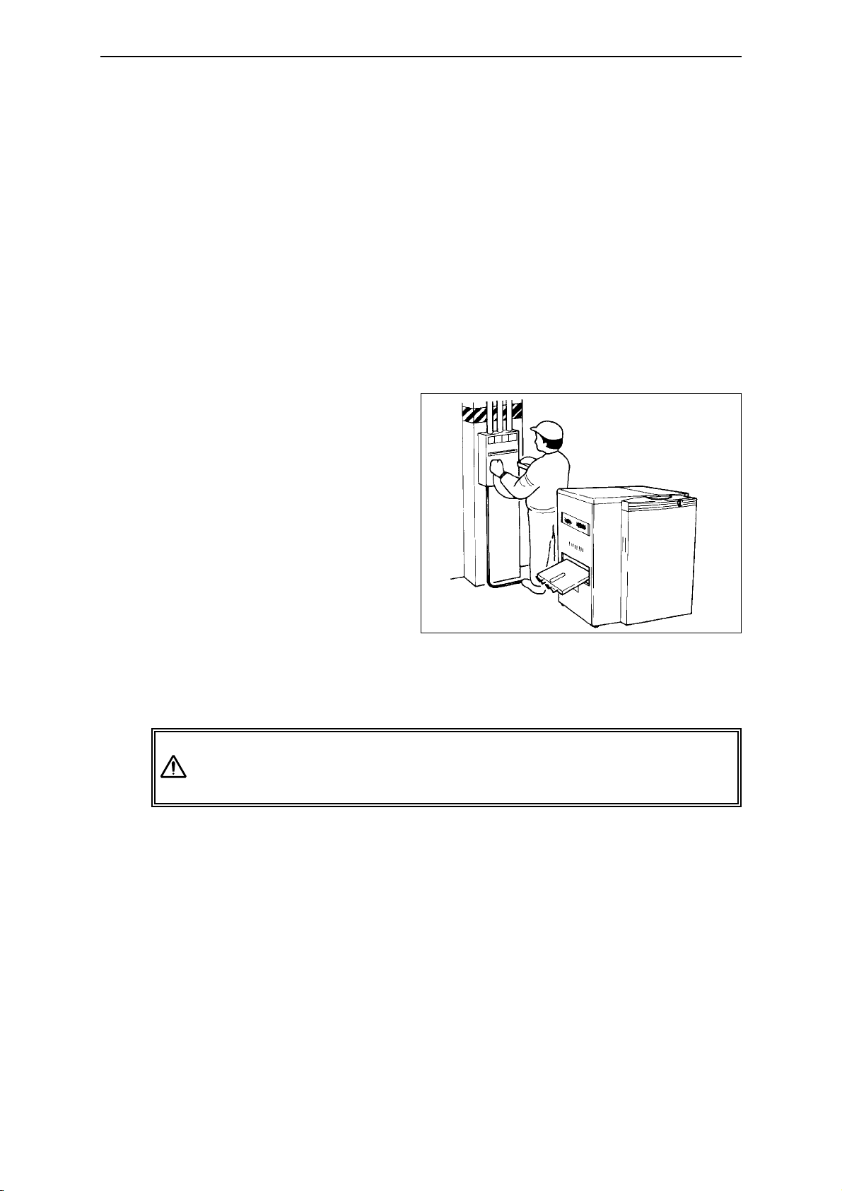
• Grounding connection
- In order to prevent
electric shock at the AC
power supply unit, be
sure to connect the
ground in accordance
with operation site
regulations (resistance:
less than 100 ohms)
using the SDP-Eco 1630
III exclusive wire.
- Even when the user's
present facility outlet can
be with the SDP-Eco 1630 III power plug with ground, make sure that
the ground pole on the outlet is connected with ground in accordance
with operation site regulations (resistance: less than 100 ohms)
Following all relevant local wiring regulations, prepare a grounded
(less than 100 ohms) power supply outlet that can accept this
machine's power plug.
• Power supply
- Prepare a power supply that satisfies all the requirements stipulated in
the specification sheet.
- Always provide circuit breakers for unit or devices that use water or
chemicals.
- Please entrust all wiring, connections and other electrical work to an
authorized electrician.
•
Maintenance and safe passage during emergencies
A minimum of 60 cm clearance is required around the machine at all
times to afford adequate space for maintenance and safe passage during
emergencies. Never allow this space to become blocked with any
objects, wires, or other obstacles.
Warning
Page 10
SDP-Eco1630 III USERS MANUAL
- 2 -
Chapter 1 On Safety
• This machine incorporates a power supply unit.
Do not use a bubble type extinguisher when a fire occurs. It may cause
electric shocks. Place a powder type extinguisher near the machine.
• The SDP-Eco 1630 III is equipped with a leakage circuit breaker.
If a short circuit occurs in the machine, the breaker is automatically
activated and shuts off the circuit.
Occasionally the main unit will not activate when you turn ON the
Power Switch because the leakage breaker inside the main unit
has turned itself OFF.
In such a case, contact your local dealer where you purchased the
machine and ask a service person to check out the condition.
• This machine incorporates high current electrical circuits.
Touching the electrical circuits of this machine with any part of your
body can cause serious injury or death. Please contact the dealer where
you purchased this machine when maintenance or inspections are
required.
•
Safety switches
To ensure operator safety, this machine is provided with safety switches.
If a front door is opened while the machine is running, a safety switch is
activated and operation is immediately stopped.
(Refer to "Chapter 2 Names of Machine Component and Parts".)
Warning
Page 11
Chapter 1 On Safety
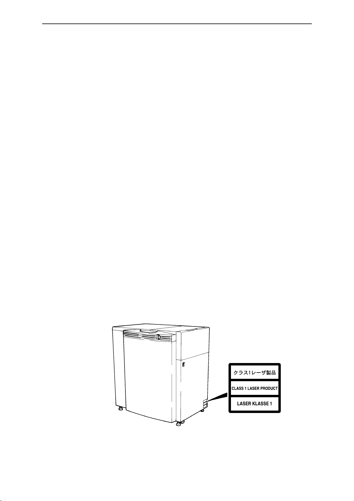
• LASER SAFETY.
The SDP-Eco1630 III is certified as a Class 1 laser product under the U.S.
Department of Health and Human Services (DHHS) Radiation
Performance Standard according to the Radiation Control for Health and
Safety Act of 1968. This means that the recorder does not produce
hazardous laser radiation.
Since radiation emitted inside the SDP-Eco1630 III is completely
confined within protective housings and external covers, the laser beam
can not escape from the machine during any phase of user operation.
• CDRH REGULATIONS.
The Center for Devices and Radiological Health (CDRH) of the U.S.
Food and Drug Administration implemented regulations for laser products
on August 2, 1976. Compliance is mandatory for products marketed in
the United States. The level shown in the figure indicates compliance
with the CDRH regulations and must be attached to laser products
marketed in the United States.
•
For European model
The SDP-Eco1630 III is classified as a CLASS 1 LASER PRODUCT in
accordance with IEC Pub 1.1 825 1984.
Ordinary operation will not release laser radiation into the work
environment. Do not remove any of the safety covers for this product or
release any of its interlock switches. Laser radiation may cause injuries to
your body (e.g. weakened eyesight, skin cancer).
- 3 -
Page 12
1.2 Warning labels and attachment positions
Warning labels are attached to dangerous parts or areas of the machine. All
operators and maintenance personnel must follow the instructions written on
these labels.
- Do not remove or deface any of these warning labels.
- Labels must always be clearly visible without any obstacles shielding or
obscuring them.
- If a label is removed or defaced, replace it with a new warning label as
soon as possible. Please contact the dealer where you purchased this
machine for new labels.
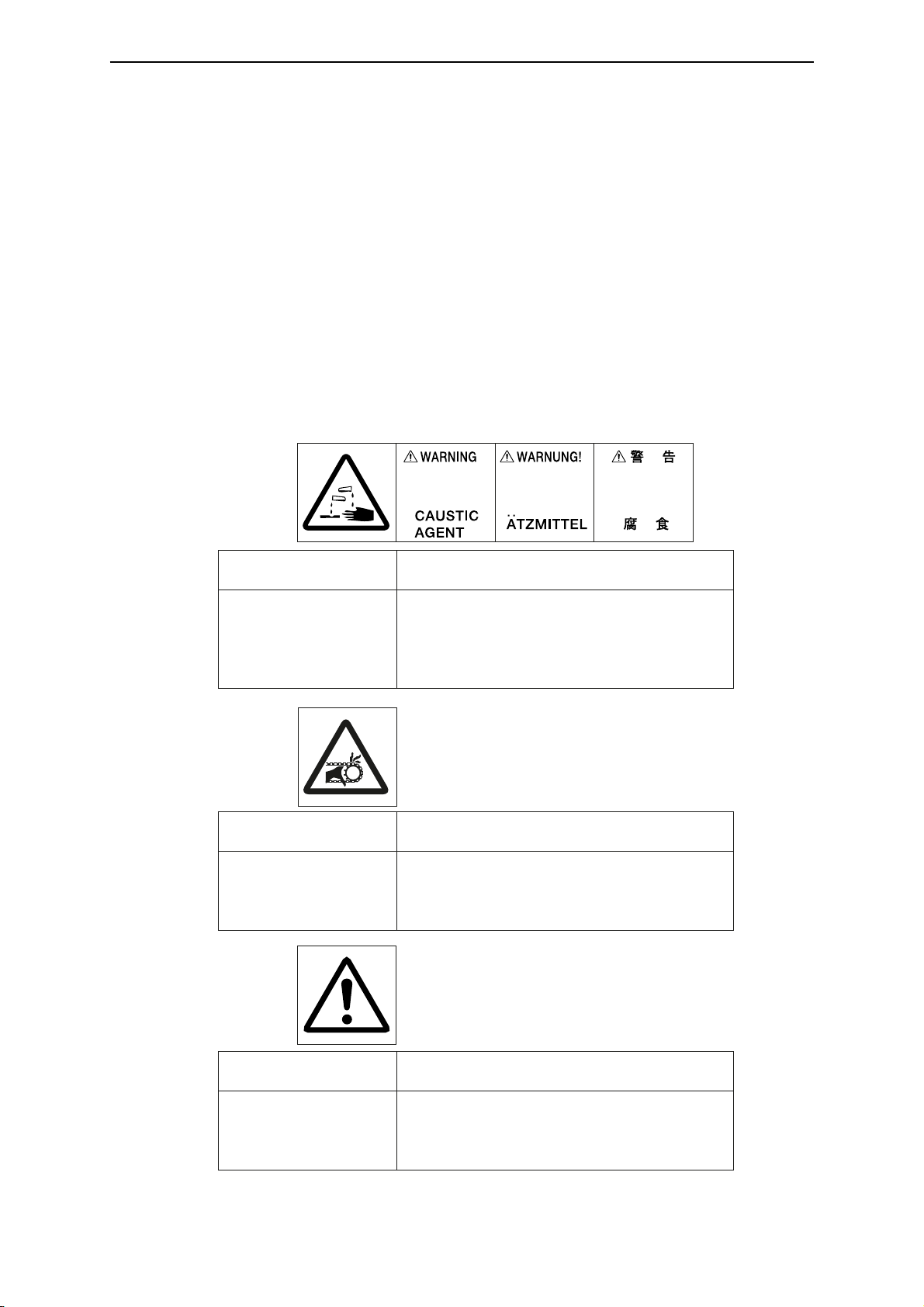
•
Types of warning labels
Hazard
Safe handling method
Contains processing
chemicals. Direct contact
with these chemicals due
to splashing or overflow
may result in skin.
irritation, blindness, or
burns.
Always wear protective gear such as safety glasses,
rubber gloves, masks, and rubber aprons.
Read all instructions and warnings for processing
chemicals.
Hazard
Hands or fingers may get
caught.
Keep hands, fingers and the rest of the body away
during operation. Always turn OFF the main power
supply and the power switch on the machine before
approaching.
Sections marked with this
label contain functions or
components which could
cause personal injury.
Keep hands, fingers and the rest of the body away
from the machine while it is running. If you must
physically touch the machine, always turn the
power supply OFF beforehand.
Safe handling method
Safe handling methodHazard
SDP-Eco1630 III USERS MANUAL
- 4 -
Chapter 1 On Safety
(1) Caustic
agent
(2) Hazardous
Moving
Section
(3) Caution
Page 13
Chapter 1 On Safety
- 5 -
Chapter 1 On Safety
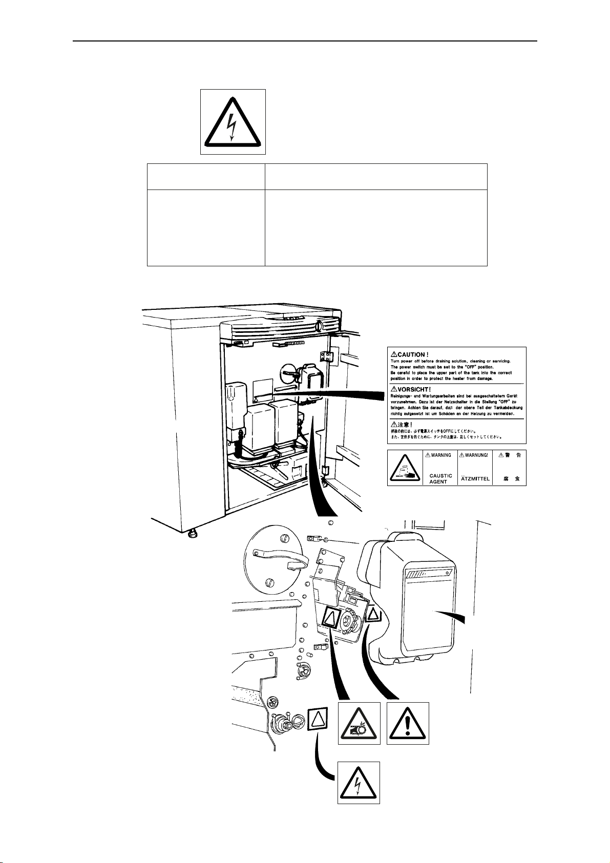
• The locations of the machine's warning labels are shown below.
(1)
(4) Electric
shock
(2) (3)
(4)
Cutter blade
replacement
procedure
Safe handling methodHazard
There are sections where
the voltages are
dangerously high. Direct
contact with these sections
(marked with this label) can
cause severe shock and
potentially fatal injuries.
The parts or sections marked with this label should
be avoided. Be careful not to touch them with your
bare bands or any part of your body.
Page 14
SDP-Eco1630 III USERS MANUAL
- 6 -
Chapter 1 On Safety
1.3 Handling processing chemicals
The SDP-Eco 1630 III uses processing chemicals to activate and
stabilize exposed plates. The processing chemicals used in this
machine are not generally dangerous to humans, but failure to use
them in the correct manner is dangerous. Be sure to handle all
processing chemicals with care.
Cautions for use of processing chemicals
Inflammation may occur if processing chemicals come in contact
with the eyes or skin, so be sure to wear protective gear (safety
goggles and rubber gloves) when handling the chemicals.
Keep out of reach of children.
What to do in case of emergency
If chemicals come in contact with the eyes, immediately rinse with
clean running water for at least 15 minutes. If the inflammation
persists, consult an eye specialist.
If chemicals come in contact with the skin, immediately rinse under
clean running water.
If chemicals are swallowed, immediately consult a physician.
Report the ingredients of the chemical or solution to the physician.
Cautions for handling waste chemicals
These chemicals have high COD and pH levels (especially the
activator) and cannot be disposed of by simply pouring them down
the drain. Please have processing chemicals removed by a
certified waste management specialist.
Warning
Caution
Caution
Caution
Page 15
Chapter 1 On Safety
- 7 -
Chapter 1 On Safety
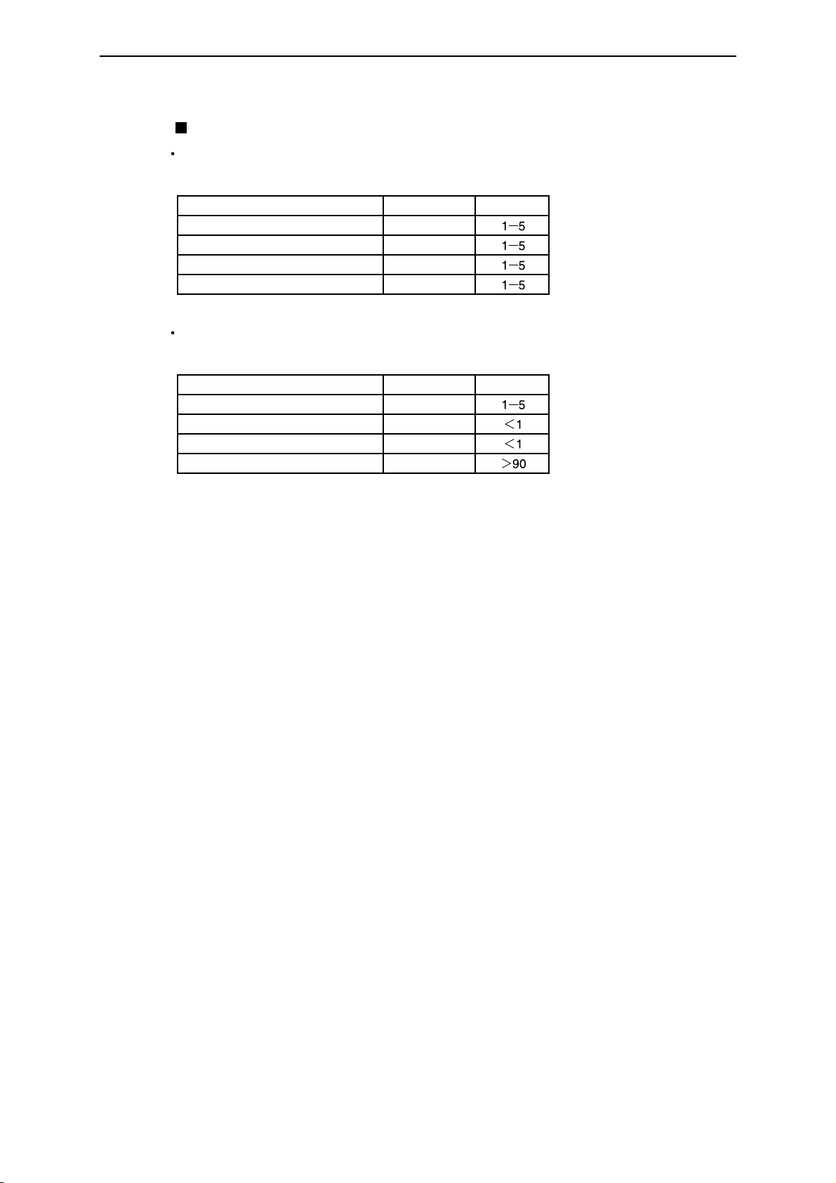
Processing chemical components
Activator (SLM-EAC)
Mixture: (aqueous chemical)
pH: approx. 13.4
Composition CAS No. Percentage
Potassium hydroxide
Potassium sulfite
Sodium sulfite
N-amino ethyl ethanolamine
Stabilizer (SLM-EST)
Mixture: (aqueous chemical)
pH: approx. 6.0
Composition CAS No. Percentage
Phosphate
Tri-ethanol amine
Heavy sodium sulfite
Water
1310-58-3
7646-93-7
7757-82-6
111-41-1
7778-77-0
102-71-6
7631-90-5
7732-18-5
Page 16
SDP-Eco1630 III USERS MANUAL
- 8 -
Chapter 1 On Safety
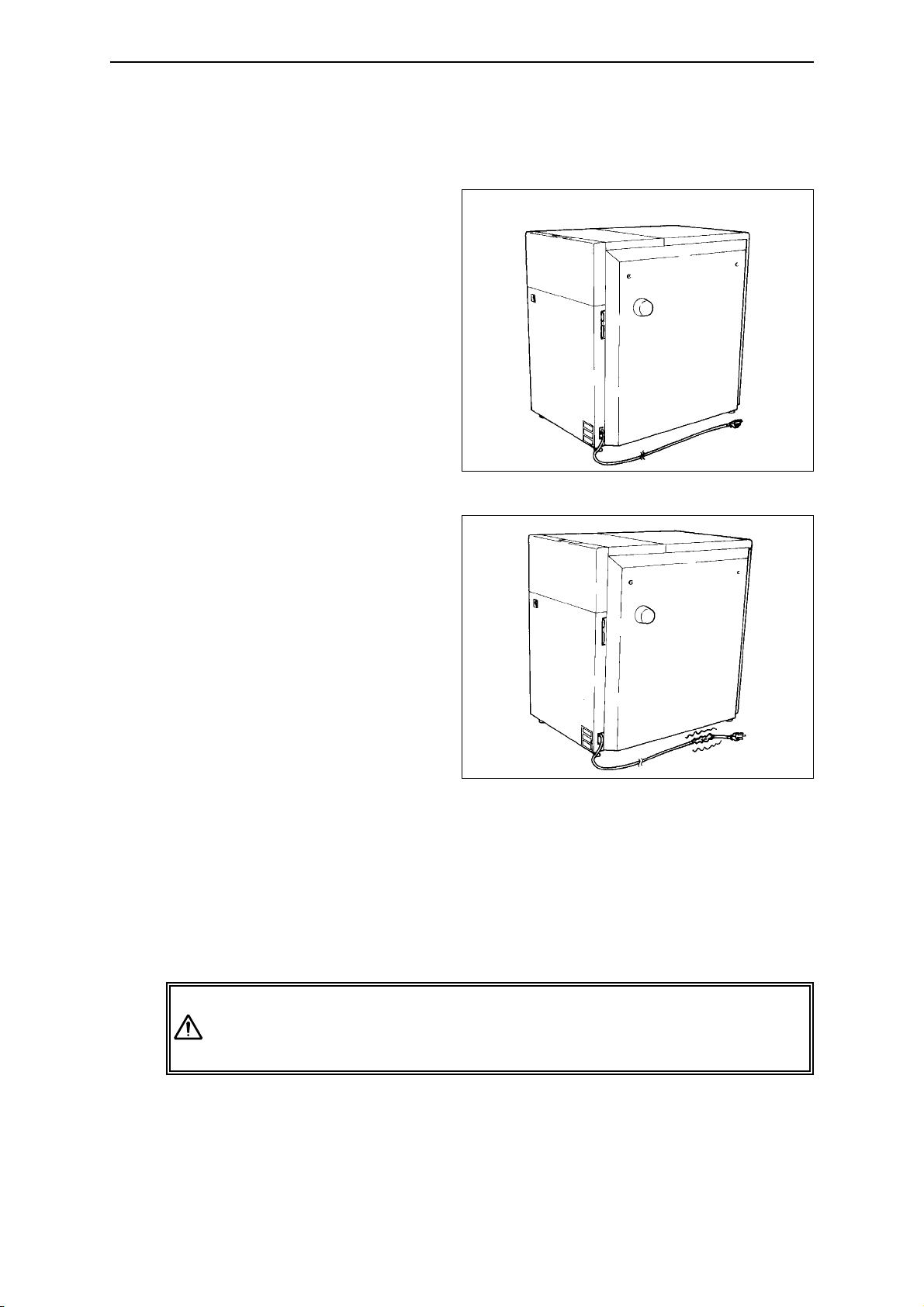
1.4 Before connecting the power cable
• Power supply
- Check that the power
switch on the SDP-Eco
1630 III is turned OFF
before connecting the
power plug to the user's
power outlet. (Refer to
"Chapter 2: Names of
Machine Component and
Parts".)
•
Power cables
- Always use grounded
power cables when
connecting to this
machine.
- If you find anything that
might indicate power
cable damage such as
unusual deformations or
surface flaws, immediately turn OFF the power
supply, pull the power
plug from its outlet and
contact the dealer where you purchased this machine.
- Do not place heavy objects or articles with sharp blades anywhere on the
power cable or forcefully pull at it.
- Never connect the power cable to a shared or overloaded outlet or
distribution socket.
- Please contact our nearest dealer before attempting to extend the power
cable.
If you notice any problems with the power cable such as scratches
or deformities, immediately turn OFF the main power supply switch
and contact the dealer where you purchased this machine.
Power plug with earth wire
Warning
Page 17
Chapter 1 On Safety
- 9 -
Chapter 1 On Safety
1.5 Operation precautions
• Do not turn the machine's power supply ON or start operation until this
manual has been thoroughly read and fully understood.
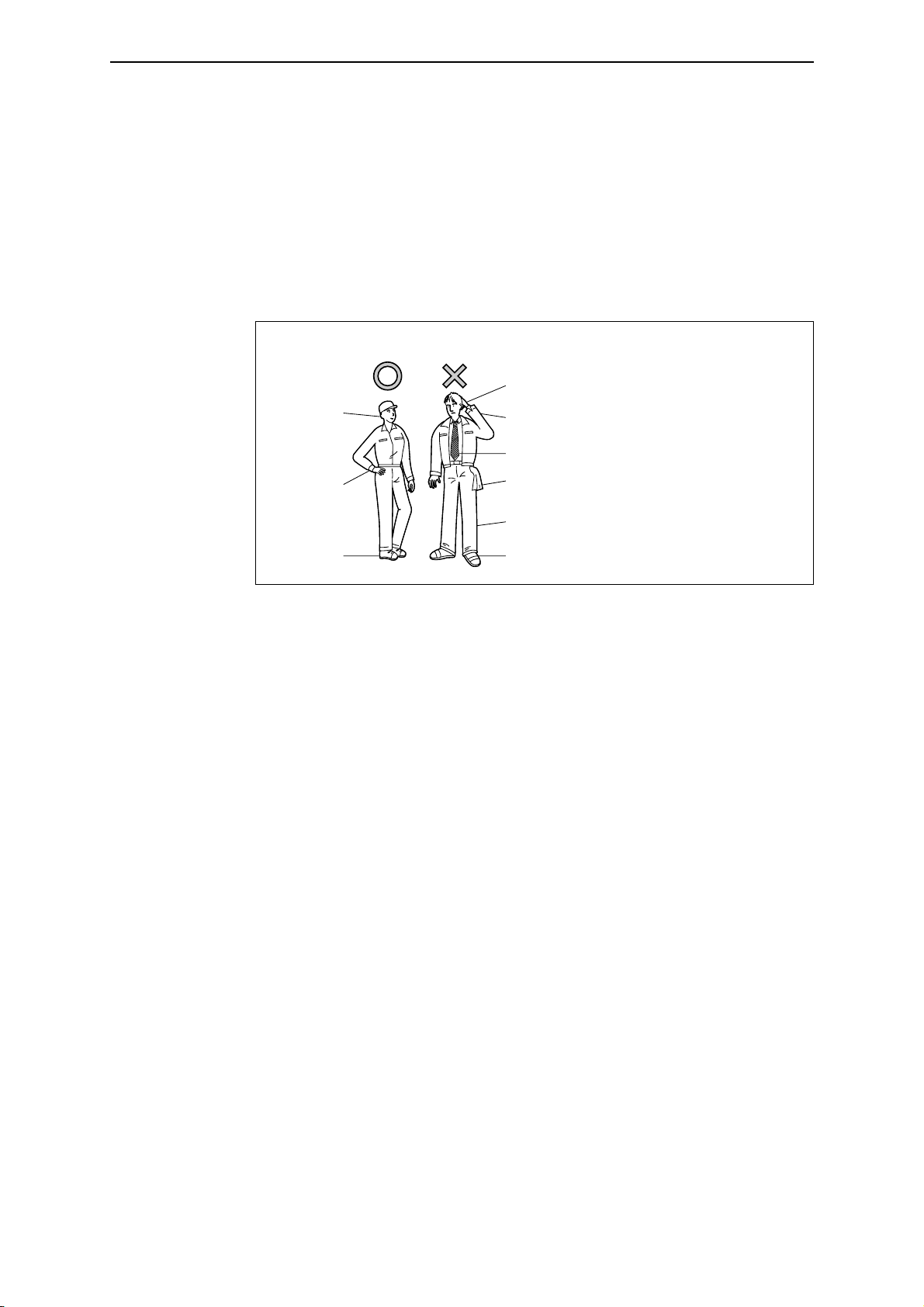
• All operators must wear appropriate work clothing and should never wear
necklaces, scarves, or other accessories which could be caught by moving
parts and cause accidents.
• Do not operate the machine if you feel in anyway sick, nauseous or
unsteady.
• If you notice that the machine is in any way abnormal, immediately report
the situation to your supervisor for appropriate action.
• The SDP-Eco 1630 III can perform continuous automatic operation, but it
must not be operated continuously without an operator in attendance.
An operator trained to take appropriate initial corrective actions should
always be in attendance to deal immediately with any emergencies that
may arise.
• When your SDP-Eco 1630 III will not be operated for an extended period
of time, be sure to unplug the power cord. Check for any dust or
contamination in the outlet, power plug, and/or the AC power socket on
your SDP-Eco 1630 III at least once a year.
• During operation, do not open any of the unit's doors or covers. Opening
these doors or covers may be hazardous to the safety of operators and
other persons working in the vicinity, and may also damage the machine.
• Power failure
If a power failure occurs due to an external reason, immediately turn OFF
the power switch and the SDP-Eco 1630 III.
When power is recovered, supply power again, referring to "4.2 Turning
ON the power switch".
Appropriate Unacceptable
Cap
Gloves
(or wet hands)
Open cuffs
Loose or dangling necktie
Always avoid clothing, gear, or
accessories that could in any way
be caught up in the machine.
Buttoned
Safety shoes
(preferable)
Items hanging from clothes
Over-long trousers
Slippers or sandals
Page 18
SDP-Eco1630 III USERS MANUAL
- 10 -
Chapter 1 On Safety
1.6 Precautions during transport and installation
• The weight of the SDP-Eco 1630 III is described in "Chapter 9:
Specifications"Make sure the floor is fully capable of handling 2500 N/m
2
(approx. 55 lbs/ft2) or heavier loading before installing the SDP-Eco 1630 III .
•
Transport and installation
This machine's transport and installation must always be handled by
engineers and contractors assigned by Mitsubishi Paper Mills Limited.
We shall bear no responsibility whatever for any unit breakage, damage,
or malfunctions caused by or during transport or installation performed by
anyone other than the above specified personnel. Whenever your
machine must moved, transferred, or reinstalled, please entrust all
procedures to our nearest branch office or dealer.
1.7 SDP-Eco 1630 III Installation
• Installation environment
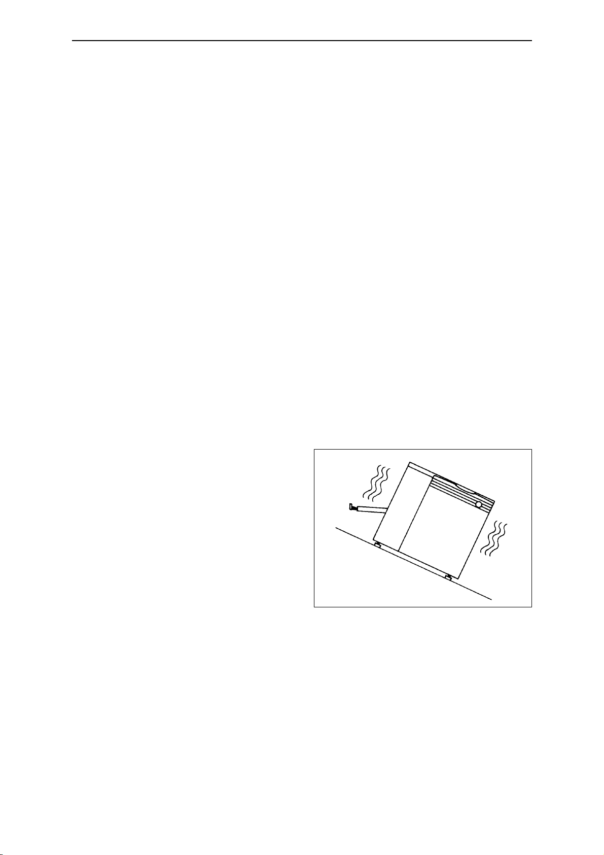
Installing the machine in the following locations may cause machine damage
or malfunctions. Do not install the machine anywhere that is exposed or
subject to:
* Locations with strong and/or
persistent vibration
* Locations with an uneven
floor
Page 19
Chapter 1 On Safety
- 11 -
Chapter 1 On Safety
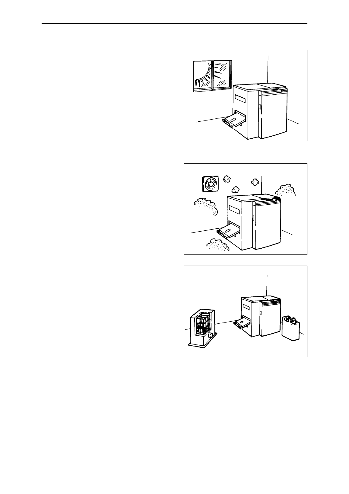
* Locations in direct sunlight
* Locations with high
temperature and/or humidity
(outside the normal range of
Temp.: 18 to 28˚C,
Rel.humidity: 50 to 70%)
* Locations where dew
condensation is a factor
* Locations with sudden,
drastic temperature changes
* Locations where excessive dirt,
grime or dust are factors
* Locations in the vicinity of
flammable gases or liquids
* Locations having corrosive
chemical vapors, mists, or
gases
* Locations with a nearby heat
source (such as a radiator or
heater)
* Locations with electrical
interference such as voltage
fluctuations or line noise.
* Locations with devices which
emit sparks or electromagnetic
radiation
•
Ventilation
Please ensure sufficient ventilation during the operation of the equipment to
avoid odor in high density.
Page 20
SDP-Eco1630 III USERS MANUAL
- 12 -
Chapter 1 On Safety
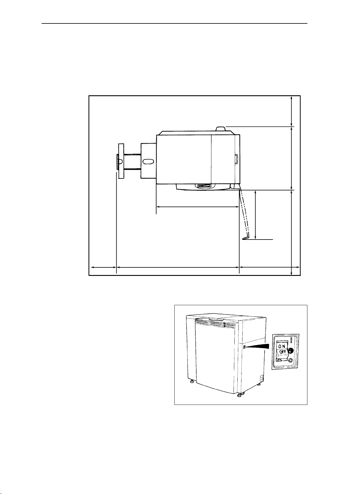
• Installation space
As shown in figure below, clearance is required around the machine at all
times to assure adequate space for maintenance and safe passage during
emergencies.
1.8 Maintenance
• Maintenance that requires tools may only be performed by persons who
have been specially
trained with our authorized
curriculum.
• During machine mainte-
nance, the operator must
make it clear that the
machine should not be
turned ON and prevent
any person other than our
authorized technician(s)
from touching the
machine.
• Be sure to turn OFF the power switch and remove the power plug from
the outlet before you start maintenance, cleaning or repairs.
Power switch
(Unit: cm)
40 or
longer
79.5
40 or
longer
70 or longer
146.5
66.9
100
100 or
longer
Page 21

Chapter 1 On Safety
- 13 -
Chapter 1 On Safety
1.9 Machine disposal
• To protect the environment, always commission a special authorized
contractor to dispose of your old machine(s).
• Commission an ordinary contractor to dispose of parts discarded or
replaced during the repair processing.
Page 22

SDP-Eco1630 III USERS MANUAL
- 14 -
Page 23
Chapter 2 Names of Machine Components and Parts
Chapter 2 Names of Machine Components and Parts
The SDP-Eco 1630 III consists of the following parts.
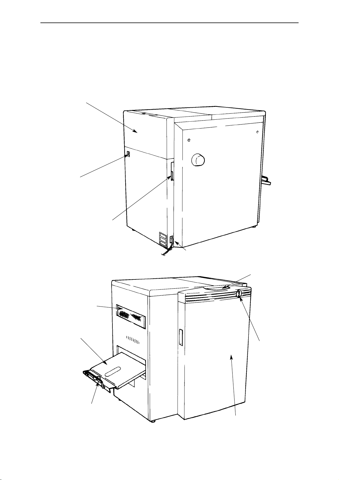
2.1 Main unit
- 15 -
Power switch
Plate setting cover
Wide SCSI connector
Operation panel
Front door
Nip roller
clearance handle
Filter
Plate receiving
tray
AC power socket
Arm
Page 24
SDP-Eco1630 III USERS MANUAL
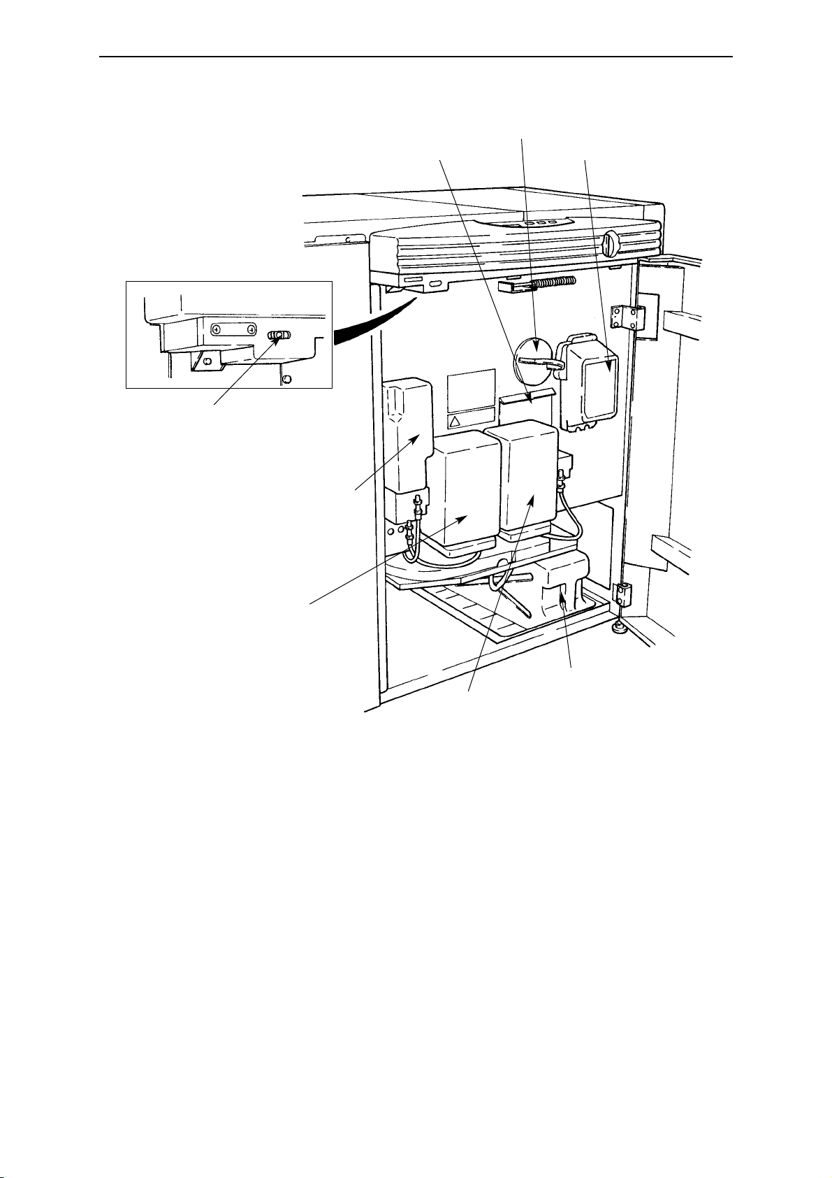
- 16 -
Safety switch
Rinse water
replenisher bottle
EST replenisher
bottle (stabilizer)
EAC replenisher
bottle (activator)
Waste chemical tank
Plate take up unit
Cutter unit
Cylindrical lens
Page 25

Chapter 2 Names of Machine Components and Parts
- 17 -
2.2 Operation panel
(1) Display panel
The operation mode, error messages, and setting values for various
parameters are displayed on this panel.
(2) Power ON/OFF key
The power ON/OFF key is used to turn OFF the power after a processor
cleaning operation. This key is used for the usual ON/OFF operation.
(3) ON LINE lamp
The ON LINE lamp is lit during transmission or standby status between
the SDP-Eco 1630 III and host computer.
(4) LOADED lamp
The LOADED lamp lights when a film is loaded and at its exposure
position.
(5) Stop key (Reset)
The STOP key is used to interrupt the exposure of a plate. If the exposure
is interrupted, the plate will be cut and discharged. This key is also used
to cancel errors and to turn OFF the error buzzer.
(6) key
The key is used to switch the user's mode between remote and local.
Also it returns the menu to the upper level.
(7) Select key
The SELECT key is used to move the cursor or change parameters.
(8) key
The key is used to enter parameters or to execute various
commands.
ENT.
ENT.
MENU
MENU
(2)
(1)
(3)
(4)
(5)
(6)
(7)
(8)
Page 26

SDP-Eco1630 III USERS MANUAL
2.3 Safety switch
This machine is equipped with a safety interlock switch which detects the
front door's open/closed status.(See page 16) If this switch detects that the
front door is open, this machine cannot perform any operations.
If the front door is opened during data transmission from the host
computer, image exposure or plate transfer, all machine operations
stop. This will cause problems with data transfer and in the image data.
Use of controls or adjustment or performance of procedures other
than those specified herein may result in hazardous radiation
exposure. Operations or adjustments other than those specified
herein may result in damage to your body(e.g.weakened eyesight,
skin cancer).
- 18 -
Caution
Warning
Page 27

Chapter 3 Handling Plates
Chapter 3 Handling plates
3.1 Plate setting
1) Open the plate setting cover and,
holding the lever with your thumb,
take the spool shaft out.
2) Refer to your plate width, and
align the edge of the spool plate
boss to the groove in the spool
shaft. The spool shaft grooves are
numbered from outer side in the
following order: 414, 404, 400,
370, 340, 335, 324, 310, 305, 279,
254, and 229.
Red tape is affixed to the
reference side of the
spool shaft.
3) To prevent the reference side of
the spool plate from shifting from
its designated position, insert a
screw driver into the set screw
hole and firmly fix the set screw to
the spool shaft.
Always fix the set screw on the
flat side of the spool shaft.
- 19 -
Lever
Plate setting cover
229 (9)
254 (10)
279 (11)
305 (12)
310 (12 1/5)
Marker
Spool plate
Set screw
Red tape
Spool shaft
Edge of boss
400 (15 3/4)
324 (12 3/4)
335 (13 3/16)
340 (13 3/8)
370 (14 9/16)
404 (15 7/8)
414 (16 3/10)
Caution
Page 28

SDP-Eco1630 III USERS MANUAL
4) Lower a roll of plate (wound in
the same direction as in the figure
on the left) down over the spool
shaft. (The shaft should be
standing vertically with the
reference side of the spool plate as
its base.).
Firmly press the edge of the plate
roll against the spool plate
(reference side) until they touch
equally all around the periphery of
the roll.
5) Firmly snap the contact side of the
spool plate down over the spool
shaft and continue pressing the
plate (contact side) downward to
the edge of the plate roll until
there are no intervening gaps.
Position the contact side of the
spool plate so that its set screw is
positioned 180
o
opposite the one
on the reference side.
The two set screws are
fixed 180
o
opposite each
other to prevent rotational
imbalance due to the
weight of the screws.
- 20 -
Plate
Make sure that the lateral edges
of the plate are still even after
the roll is set on the spool shaft.
Spool plate
(contact side)
Plate
No gaps here.
Spool plate (reference side)
Set screw
(contact side)
Must be located
exactly (180o)
opposite the one
on the reference
side.
Set screw
(reference
side)
Note
Page 29

Chapter 3 Handling Plates
Confirm that there is no gap
between the plate roll and the
spool plate and that the set screw
is placed in the correct position
and then tighten the set screw.
6) Turn ON the power switch to the
main unit. After completion of the
initialization process, grab the
handle on the right side, open the
magazine cover, and load a plate
roll which has been mounted on a
spool shaft.
Refer to "4.1 Cable
connection check", "4.2
Turning ON the power
switch" and "4.3
Initialization" in Chapter 4
"Operation" when turning
ON the main power
switch.
7) Put the spool shaft holder on the
spool set guide and set the guide
into the SDP-Eco 1630 III.
Position the shaft with its red mark
toward the back of the machine
(on the right side).
8) Turn the nip roller clearance
handle (located at the panel
bottom) until it is horizontal. This
cancels the main roller nipping.
Gently insert the plate into the
clearance in the guide roller.
- 21 -
Gently insert the plate.
Turn the nip roller
clearance handle until
it is horizontal.
Note
Page 30

SDP-Eco1630 III USERS MANUAL
A buzzer sounds when you start
inserting the plate. Insert the plate
further until a second buzzer
sounds. At the position where the
buzzer sounds, turn the nip roller
clearance handle back to its
vertical position to close the nip.
Insert the plate edge until
the second buzzer sounds.
If you insert it too far (30
mm or more), the plate
may jam.
Finally, gently holding the right
and left ends of the spool plate
rewind the plate to take up any
slack. Close the plate setting
cover. The plate setting is now
completed.
Skewing or meandering
may occur during feeding
depending on how carelessly the plate was
inserted.
Always insert the plate
evenly, holding its left and
right edges with both
hands.
Follow the procedures "4.4 Data
input for the set plate" and
"4.5 Execution of Pre. Feed
command" to input data for the set
plate. To prepare for the exposure:
Remove any section of the plate
that has been fogged by friction
during preliminary feeding.
- 22 -
Hold the spool plate to rewind the plate.
Tighten the slack on the
plate roll using both hands.
Close the plate setting
cover.
Insert the plate edge until the second buzzer
sounds and secure it there.
Turn the nip roller
clearance handle back
until it is vertical.
Caution
Caution
Page 31

Chapter 3 Handling Plates
3.2 Plate end processing
When plate end is displayed, remove the plate and re-set a new one following
the procedure below.
1) When is displayed on the panel:
The plate ended during exposure, so it is discharged from the processor.
Stop the buzzer by pressing the (reset) key.
After the plate is discharged, press the key to shift to the local mode,
and mount a new plate following the procedure mentioned in "3.1 Plate
setting".
Whether or not data will be
exposed depends on the
amount of exposure data
remaining when the plate end
is detected.
2) When is displayed
on the panel:
Plate ended at the beginning of an
exposure, so the remainder is
shorter than the processor's
minimum transfer length. Please
remove the plate.
1. Open the front door and remove
the plate through the plate removal
port.
2. Close the door and press the
key to return to the local mode.
3. Re-set the plate following the
procedure mentioned in "3.1 Plate
setting".
- 23 -
Cover for the plate
removal port
Plate removal port
<Plate End>
MENU
Note
Pick up plate
Page 32

SDP-Eco1630 III USERS MANUAL
- 24 -
Page 33

Chapter 4 Operation
The SDP-Eco 1630 III is a SCSI device. Turn ON the power switch for this
machine first, and complete its initialization routine. Then turn ON the
power switch to the host computer (RIP computer).
Be sure to turn OFF the power switch to the host computer (RIP computer)
when turning OFF the power switch for this machine.
Never open the front door or plate setting cover unnecessarily. Do
not open the plate setting cover except when replacing the plate roll.
Otherwise, the plate being processed may be adversely exposed. If
the front door is opened while the plate is being fed, it will adversely
affect the plate's image quality and feed state.
4.1 Cable connection check
After checking that the entire system including the host computer (RIP
computer) is shut down, check that all cables are connected correctly. The
figure below shows cable connections and locations. The cables used here
should be SCSI connection dedicated cables.
Do not use cables other than
the provided SCSI cables.
If the cable must be extended,
please purchase the optional
differential unit. This ma-
chine is incorporated with an
active terminator, so that this
differential unit can be
mounted internally.
Chapter 4 Operation
- 25 -
Wide SCSI
connector
Do not open the cover
during operation
Do not open the door
during operation
Caution
Page 34

SDP-Eco1630 III USERS MANUAL
4.2 Turning ON the power switch
Before you turn ON the power switch of the main unit, check the following
points.
1) Processing chemical has been properly supplied to the processor.
2) The front door and plate setting cover are securely closed and the covers
are properly mounted.
In a SCSI, the power switch must be turned ON from the peripheral unit.
First, check that the power switch for the host computer (RIP computer) is
shut down. Then, turn ON the machine power switch.
If any error is detected during initialization after turning ON the power switch, it is
immediately displayed.
4.3 Initialization
When the power switch to the SDP-Eco 1630 III is turned ON, the machine
performs an initialization sequence which includes a number of routines to
confirm that it is ready for normal operation. Checked items include:
- Internal setting check
- Plate mounting check
- Polygon mirror function check
- Waste chemical tank level check
- Activator (EAC) level check
- Stabilizer (EST) level check
- Home position check for each moving part
•
Panel display flow after machine startup
- You can cancel the operations after "Cleaning", during the sequence of this
process, by using the key.
- The "Heating" window informs you if a heater has not yet reached the specified
temperature. ("P" signifies the process heater, and "R", the roller heater.)
- 26 -
Caution
Note
Initializing....
Note
Cleaning
Levels Dryer H/L?
Heating
Cleaning
Start OK
Page 35

4.4 Data input for the set plate (This procedure is necessary when
loading the plate.)
(1) Press the key to display the .
(2) Press the key to display , which is a lower
level of the menu.
(3) Use the key to select the data registration number, plate type, plate
width, or length of plate roll, then press the key to flash the cursor
(indicating mode change).
(4) Press the key after changing the data using the or key.
• Input the plate data and press the key. Press the key once to call
up the display and press the key once more to call up
the display and switch to the on-line mode.
(Example)
1) Selection of Data Memory Channel (From M0 to M3)
Press the key in order to start the
cursor key flashing and select M0 to
M9 using the key or the
key. Press the key to register the
data channel.
2) Selection of plate type (From F100 to F175)
Press the key or the key to
move the cursor to the F100 display
(plate type). Press the key to
start the cursor flashing. Select the
plate type (F175, R175) using the
key or the key and press
the key to register the plate type.
3) Selection of the plate width (From 404 to 414)
Press the key or the key to
move the cursor to the 404 display
(plate width). Press the key to
start the cursor flashing. Select the
plate width using the key or the
key and press the key to
register the plate width.
ENT.
ENT.
ENT.
ENT.
ENT.
ENT.
Start OK
< Plate Data >
MENU
ENT.
Chapter 4 Operation
- 27 -
M0 F175 414 61m
M3 F100 404 37m
If setting
M3
Cursor
M3 F100 404 37m
M3 F175 404 61m
M3 F175 404 61m
M3 F175 414 61m
MENU
ENT.
< Plate Data >
< Plate Data >
M0 R 1 7 5 414 00m
ENT.
Note
ENT.
Page 36

SDP-Eco1630 III USERS MANUAL
- 28 -
4) Inputting the value for the remaining amount of plate (61m to 46m)
Press the key or the key to
move the cursor to the remaining
amount display. Press the key or
the key to start the cursor
flashing. Change the remaining
amount using the key or the
key and register the value with
the key.
*Press the key to return to the original menu when you finish changing settings.
4.5 Execution of Pre. Feed command (This procedure is necessary
when loading the plate.)
Close the plate setting cover after the plate roll is set.
(1) Return the menu to the upper level menu using the key.
(2) Select Pre. Feed (preliminary feeding mode) using the key.
Press the key to move to the lower level menu
for the preliminary feeding mode.
(3) Use the key to set the plate feeding number to either "1" or "3" -- for
"Feed Count 1".
(4) Start preliminary feeding with the key.
- Press the key after the preliminary feeding. Press the key once to
call up the display. Press the key once more to call up the
display and switch to the on-line mode.
- Normally, a preliminary feeding must be performed to remove the fogged area
after loading a new plate.
Start OK
MENU
< Plate Data >
MENU
ENT.
M3 F175 414 61m
M3 F175 414 41m
ENT.
MENU
< Plate Data >
ENT.
MENU
Note
ENT.
Page 37

Chapter 4 Operation
- 29 -
4.6 Exposure
The machine has two exposure modes: remote exposure which performs
exposure using data provided from the host computer, and local exposure
which performs laser test exposure and re-exposure.
•
Remote exposure
After entering remote mode (ON LINE lamp is lit), give the exposure
command through the host computer (RIP computer). While exposure is in
progress, "Exposing ***%" is displayed on the panel display. "***%"
indicates the percentage currently exposed.
[Display during remote exposure]
The panel display changes as shown below during the exposure.
•
Local exposure
[Laser Test Expo.]
(1) Confirmation and input of the plate type, resolution and light intensity
1) Use the key to call up display.
2) Select using the key and press the key.
3) Press the key while is displayed.
4) Plate type, resolution and light intensity are displayed.
(Example) (F175 1200 dpi Light intensity 200)
5) Press the key to change the resolution. Select the desired
resolution from among 12 (1200 dpi), 15 (1500 dpi), 18 (1800 dpi)
and 24(2400dpi) using the key. Register the resolution using
the key.
6) Press the key to move the cursor to the light intensity value
display and then press the key.
7) Change the light intensity value using the key or the key.
Press the key to register the light intensity value.
Press the key to return to the previous menu if no change is necessary or
setting is discontinued.
MENU
Data transmission start
Data transmission end
Image data exposure start
Image data exposure end
Plate is being discharged
Completion
MENU
<Laser>
ENT.
< Plate Data >
Laser Test Expo.
Data Transferring
Exposing 0%
Exposing 100%
Discharging
Complete
ENT.
F175 (1 2) 200
ENT.
Note
ENT.
ENT.
ENT.
Page 38

SDP-Eco1630 III USERS MANUAL
- 30 -
(2) Exposure
1) Press the key to call up display. Move the
cursor to the Laser Test Expo. display and press the key.
2) After Laser Test Expo. display appears, Y N is displayed. Choose
'Y' with the cursor key and press the key. The laser test
exposure will start. (Refer to '6-2 Laser menu')
- When the cursor key is at 'N', press the key to call up the
display.
- After completion of the test exposure, press the key once to call up the
display and press the key oncemore to return to .
- When re-adjustment of the light intensity is necessary, change the light
intensity value following step (1)-6 in the procedure above.
[Exposure Clear]
The image data which remains in the hard disk drive will be re-exposed if
exposure is interrupted during remote exposure (e.g., because of a plate end
signal). It is possible for the hard disk to keep up to 2 separations of image
data. Image data that has been exposed can be re-exposed.
1. Press the key to call up the display.
2. Select the key and press the key to move to the display
for re-exposure.
3. Select in the display. Pressing the key
shows the display for selecting unexposed or exposed data.
4. Pressing the key in the display brings up the
display.
Unexposure EXEC............Image data on the hard disk drive, which has not
yet been exposed.
Exposed EXEC.................Image data which has already been exposed.
Select EXEC and press the key to start
exposure.
5. Select and press the key to erase image data on the
hard disk drive.
- When is displayed, use the key (the red reset key)
to return to the previous window. Then press the key to return to the
window.
- Though the hard disk drive can keep image data for up to 2 separations, you
cannot select the separation data to be output.
< Plate Data >
MENU
Non Exposure Data
MENU
Laser Test Expo.
ENT.
ENT.
Note
ENT.
Laser Test Expo.
<Laser>
MENU
MENU
Start OK
MENU
< Image Data >
< Plate Data >
ENT.
Exposure
Exposure Clear
ENT.
<Exposed EXEC
Unexposure EXEC>
ENT.
Exposure Clear
ENT.
Note
Page 39

Chapter 4 Operation
4.7 Processor section
The processing chemicals are applied to the plate while it is being transferred
in the SDP-Eco 1630 III's built-in processor section. The processor section
also includes a final rinsing process which cleans the developed plates and
thus reduces paper media waste (from processing chemical stains) at the start
of printing.
You must thoroughly read "1.3 Handling processing chemicals".
• Preparing and pouring processing chemical
1) Fasten a replenishment cap on the replenisher bottle which contains the
processing chemical and set it in the tank.
Be sure to set the bottle in the appropriate tank since the SLM-EAC
and SLM-EST cause different (opposing) effects.
• Processing chemical replenishment
As the processing chemical decreases, the liquid level in the tank goes down
and finally the "Empty EST" or "Empty EAC" message appears on the display
(accompanied by a buzzer sound). Replenish the processing chemical
following the procedure below.
Replenish the processing chemical and replace the processing bottle
following the procedure below.
1) Press the key to turn off the buzzer.
2) Open the front door.
3) Add processing chemical from the container (10 liters) to the replenisher
bottle.
4) Put the cap back on the replenisher bottle and set it in the tank.
- 31 -
Rinse water
replenisher
bottle
Washing tank
Waste
water hose
SLM-EST
drainage
hose
SLM-EST
replenisher
bottle
Processor rack
SLM-EST
processing
chemical tank
SLM-EAC
replenisher
bottle
SLM-EAC
processing
chemical tank
SLM-EAC
drainage
hose
Cap
Waste chemical vat
Waste chemical tank
Caution
Caution
Page 40

SDP-Eco1630 III USERS MANUAL
• Processing chemical replacement
Replace the processing chemical every three months regardless of the number
of plates processed.
•
Preparing rinse water
1) Pour approximately 1 liter of water into the rinse water replenisher bottle
and set it in the washing tank.
2) Always make sure that the bottle is filled with water before turning ON
the power switch.
3) After turning ON the power, reset the counter in the <Rinse> menu with
the following operation.
[Procedure]
(1) Push the key to display .
(2) Select using the key, and then push the key.
(3) Using the key, align the cursor to "CLR" in the
menu.
(4) Push the key to reset the counter.
If the washing tank becomes empty of water, this will adversely affect the
plate's image quality. Replenish the rinse water everyday before starting
operation.
Replace the water in the washing tank every month. Replacement
frequency may vary depending on the quality of the water and the
season.
• Confirming the remaining amount of rinse water and replenishment
When the rinse water is running out and needs to be replenished, the "Rinse
Tank Check" message appears in the display, causing the buzzer to sound.
Confirm the remaining amount of rinse water and replenish it as necessary.
1) Press the key to turn the buzzer OFF.
2) Open the front door.
3) Remove the rinse water replenishing bottle and replenish it with rinse
water.
4) Return the rinse water replenishing bottle to its original position, and then
close the front door.
- Pressing the key to delete the above message in the display does not
reset the software counter, causing the message to appear in the display and
the buzzer to sound a while after the key has been pressed. To reset the
counter, open the front door, and then confirm the remaining amount of rinse
water, or display the window in the users menu, and then perform a
counter clearance operation. (For detailed operation, refer to the section
"Preparing Rinse Water.")
<Rinse>
- 32 -
<Rinse>
MENU
< Plate Data >
ENT.
Count 150 CLR
Caution
ENT.
Note
Page 41

Chapter 4 Operation
- If the output data is sent from the host computer to the recorder while
the above warning is being issued, the warning disappears, executing
output operation. After output operation has been completed, the
warning message appears and the buzzer sounds again.
• Handling waste liquid
Scale lines indicating capacity are marked on the waste chemical tank.
Observe the scale line carefully and dispose of the processing chemical before
it reaches the 10-liter line.
When the waste chemical tank is full, the "Waste tank check" message appears
and a buzzer sounds. (Images cannot be read at this time.)
Dispose of the processing chemical following the procedure below.
1) Press the key to turn off the buzzer.
2) Remove the cap from the waste chemical tank and dispose of the waste
chemical in the tank.
3) Put the cap back on the now empty tank and put it back in the waste
chemical vat.
- The waste chemical tank weighs approximately 11 kilograms when it
is full, so please be very careful when handling it. (Refer to "1.3
Handling processing chemicals".)
- Be careful when handling the hose attached to the waste chemical
cap. Using a crimped or twisted hose can cause chemical leakage.
• If the machine is not used for a long period
Before deactivating the machine for a long time (7 days or more),
always drain the water in the rinse water replenisher bottle.
If the machine has not been used for a long time, the processor rack roller may
stick and not rotate smoothly.
Follow the procedure below so that the processor rack roller will rotate
smoothly.
1) Open the front door.
2) Remove the replenisher bottle
from the tank.
3) Hold the handle in the processor
rack section and slightly pull out
the processor rack.
- 33 -
Handle
Processor rack
Caution
Caution
Page 42

SDP-Eco1630 III USERS MANUAL
- 34 -
4.8 Collecting exposed plates
Exposed plates are discharged into the plate receiving tray. The SDP-Eco
1630 II discharges plates image-side down. Adjust the length of the discharge
retainer arm to accommodate the maximum length of the plates used.
It is possible to continuously collect plates (up to 50 consecutive sheets).
However, we cannot guarantee trouble-free collection of such large
numbers of plates if the machine is indiscriminately discharging plates of
different lengths or if the plate type is frequently being changed.
4.9 Turning OFF the power supply and inspection at shutdown
Always, before shutting down the machine, press the power ON/OFF key to
perform the final inspection. When is displayed in the on-line mode,
press the key to return to the local mode and then press the power
ON/OFF key.
The required final inspection includes checking the chemical level in the
waste chemical tank and releasing the plate nip by turning the nip roller
clearance handle to its vertical position. Roller cleaning is also performed
during the final inspection. If this procedure is not followed, transfer errors
may occur or masters exposed on the following day may be stained or marred.
If this procedure is not followed, transfer errors may occur or plates exposed
on the following day may be stained or marred.
It is not necessary to turn ON/OFF the main power for a weekday shut-down.
For weekend inspections: at shut-down, first turn OFF the machine,
completely clean the roller, and finally turn OFF the main power supply (at
the breaker).
MENU
Start OK
4) To rotate the roller, turn the handle
in the direction indicated by the
arrow in the figure.
Rotate the roller with the handle.
Caution
Page 43

Chapter 4 Operation
When shutting down the machine by pressing the power ON/OFF key, the
dehumidifying heater will automatically run unless the main power is also shut
down. The dehumidifying heater attached below the plate setting section inhibits
condensation in the machine by heating plates when humidity is high and
temperature is low. The low temperature keeps the machine away from fire
danger.
During the final inspection, do not open the front door until the display
panel is turned off; otherwise the final inspection will stop in the middle
of the operation.
- 35 -
Note
Caution
Page 44

SDP-Eco1630 III USERS MANUAL
- 36 -
Page 45

Chapter 5 Menus and panel displays
Chapter 5 Menus and panel displays
The display panel shows the performance status of the SDP-Eco 1630 III, its
error messages, etc.
5.1 User menu
- 37 -
Page 46

SDP-Eco1630 III USERS MANUAL
• Operation status
[Remote and local]
In the remote mode, it is possible to expose data transferred from the host
computer (RIP computer). In the local mode, exposure data from the host
computer (RIP computer) cannot be accepted.
The local mode includes a "User menu" (including user maintenance
functions) and a "Maintenance menu".
[User menu]
The "User menu" provides the basic commands necessary to operate the
machine.
[Maintenance menu]
If a command or a dialog for a command that is not included in the User
menu list appears, immediately press the key several times to return
to the User menu. (Do NOT press the key.)
This menu is used to adjust the SDP-Eco 1630 III.
[Standby mode]
In remote mode, if no command is sent to the machine for 10 minutes, it
enters the standby mode.
The standby mode will be canceled whenever a command is given or
when any key on the panel except the key is pressed.
Recovery time will differ depending on whether the machine has been in standby
mode for more than 10 minutes. If the machine was left idle for more than 10
minutes, recovery will take longer because a cleaning routine is performed for
the processor roller.
[Auto power OFF]
When this machine is left in the local mode for two hours, a cleaning
routine is performed for the processor roller and the power is turned OFF
automatically.
- 38 -
MENU
ENT.
Note
Page 47

5.2 Panel operation
• Power ON/OFF key
Press this key to turn OFF the power supply to the machine and shut it
down (after cleaning the processor roller). To re-start the machine, press
the Power ON/OFF key again.
This key only works in the first local status display and does not work at
all in the remote status.
[Final inspection display]
Final inspection
Always press the Power ON/OFF key when the operation ends.
• Remote mode display
The following display appears on the panel while the remote mode is selected.
START OK
The ON LINE lamp is lit while this is displayed.
Pressing the key shows the current state of the plate.
Pressing the key shows the number of images in data remaining on the
hard disk drive.
•
Menu/command selection
Use the key, keys, and key to select menus or
commands. The key brings up the menu level in the remote and local
modes. The keys switch the menu level between remote and local.
The keys are used to shift between commands. Selectable
commands appear with one of their letters underlined. You can select
commands on the right by pressing the right key and commands on the left
with the left key.
Pressing the key when a ">" mark is shown at the right edge of the menu
display shows the next (hidden) menu to the right. (Simply reverse this step
to move to hidden menus on the left.) When you find the desired menu, press
the key. Proceed to the next menu.
ENT.
MENU
ENT.
MENU
Chapter 5 Menus and panel displays
- 39 -
Waste Tank? Nip Free Cleaning Power OFF
HDD 1/2
Amount of image data which has not yet been exposed.
Amount of image data in the hard disk drive.
Caution
Page 48

SDP-Eco1630 III USERS MANUAL
• Switch the mode between remote and local
Remote Mode Local Mode
Start OK <Plate Data>
• Shift between commands (Example)
1st hierarchy <Maintenance>
2nd hierarchy Cutter Processor> <Ver SCSI-ID>
• Command execution
There are two types of commands: one which activates machine functions
such as preliminary feeding and cutter-processor commands, and one which is
used, for example, to set numerical values.
For commands in which numerical values can be changed (Example:
Referring to P27 "4.4 Data input for the set plate")
Use the to move the cursor to the numerical value display. Press the
key to start the display flashing and change the displayed value. (In
some modes the numerical value display starts flashing from the time it is first
displayed.)
The or key increases/decreases a numerical value.
Press the key when the desired number appears.
If you wish to reset a value or interrupt the setting procedure, press the
key to return to the upper menu level without changing the currently set value
and re-start the setting procedure from the beginning by selecting the same
command.
For commands in which numerical values can not be changed (Example:
Referring to P28 "4.5 Execution of Pre. Feed command")
Use the to select the desired command. Then press the key to
execute it.
Repeatedly press the key until Start OK is displayed to return to the on-
line mode.
MENU
ENT.
MENU
ENT.
ENT.
ENT.
MENU
MENU
- 40 -
Page 49

Chapter 6 User menu
It is possible to set values affecting the machine's operation state from the user
menu. Note that some settings from the host computer are given priority and
they will be automatically changed if the host computer resets them.
Refer to '5.2 Panel operation' for details on key operation.
6.1 Plate data
The command is used to enter information on the plate to be
loaded.
• Data channel
The data channel stores the plate information. 10 different sets of plate
parameter data can be stored (from M0 to M9). The plate information consists
of plate type, plate width, remaining amount, and the set laser (depends on the
resolution for the respective plate type).
•
Plate type
You can only use the following three types of plates.
• Plate width
Each plate can be set to the following widths (displayed in mm).
< Plate Data >
Chapter 6 User menu
- 41 -
Plate type
Data
channel
Plate width
Remaining
amount
Sample panel display
M1 F175 404 60m
Note
Panel display
F175
F100
R175
Plate model
SDP-FRm175
SDP-FR100
SDP-RR175
Remarks
Polyester base
t 0.175 mm
Polyester base
t 0.100 mm
Paper base
t 0.175 mm
Page 50

SDP-Eco1630 III USERS MANUAL
• Remaining amount of plate
The remaining amount of plate should be set in meter units when you use a
new plate.
The initial setting value is 0 meter.
The remaining amount of plate is shown in 1 meter increments (0 to 75
meters) in the remote mode display
The remaining amount value is calculated by subtracting the exposed plate
length from the plate length set by the operator. The plate length for
preliminary feeding is also subtracted.
However, the accuracy of the remaining length measurement is not
guaranteed. Please regard this value simply as a reference guide.
6.2 Laser menu
The laser menu contains a command to set the laser for exposing the current
plate.
• Resolution setting
(12) ......1200dpi
(15) ......1500dpi
(18) ......1800dpi
(24) ......2400dpi
• Laser setting
From the panel, you can set the exposure laser for each resolution to be used
with the current plate.
1) Set the resolution and laser value.
2) If necessary, expose a trial sheet to adjust the laser.
- 42 -
Sample panel display
Plate type
F175 (12) 200
Resolution
Laser value
Page 51

Chapter 6 User menu
• Laser test exposure
The plate is exposed using a specific pattern to determine the most suitable
laser for each resolution. (The selected resolution is displayed on the panel
display.) The table on the previous page shows the exposure resolution
pattern. Resolution code lines are shown at the bottom of the exposed pattern.
- 43 -
100%
50%
95%
5%
Light intensity
value
10
8
Resolution code lines
1200 dpi ..... 2 lines
1500 dpi ..... 3 lines
1800 dpi ..... 4 lines
2400 dpi ..... 5 lines
0
+8
+10
(Example1200dpi)
Page 52

SDP-Eco1630 III USERS MANUAL
6.3 Pre. Feed menu
Whenever you set a new plate, a "Pre. Feed" operation is performed to
eliminate any fogged sections at the leading edge.
From the display panel, you can select whether to feed 1 or 3 sheets for this
operation. The length of each sheet is 500 mm, so if you perform a 3-sheet
preliminary feed, 1500 mm of plate will be cut, fed and disposed of.
If there are still darkened or fogged areas on the plate, perform another
preliminary feed.
6.4 Image Data menu
The SDP-Eco 1630 III incorporates a hard disk drive buffer to avoid idle time
due to differences in calculation speed between itself and the host, and to
enable quick re-exposure after an exposure was interrupted (e.g., if you use
the stop key or the plate ends).
Data written in the hard disk drive can be exposed or erased in the local mode.
Select the "Exposure" command to expose the data and the "Clear" command
to erase it.
6.5 Mode menu
In this menu, you can operate the punch (option), select a dryer level, and set
the buzzer response for different key operations.
Set the punch to ON to punch plates before image exposure or set it to OFF if
punching is not necessary.
If the machine does not contain a punch unit, the "Un-mounted" message
appears.
• Punch specifications
Two types of punch unit options can be set: the DS punch (for alternately
positionable punch) and the BELL punch.
The distance between punch holes is fixed, so it is impossible to change the
distance depending on the plate width.
[DS punch] [BELL punch]
- 44 -
220
Leading side
Leading side
386.5
Cut line
Dedicated for 335mm width plates
12 x 16
10 x 16
5 x 8
φ
5
Note
Page 53

Chapter 6 User menu
• Dryer level selection
When setting the dryer temperature, you can select either automatic or manual
(Hi or Low). Select the temperature setting which suits your plate type and
the environmental conditions.
If you select automatic setting, the dryer temperature will be set to "Hi" for
FR100 and FRm175 plates, and "Low" for RR175.
• Stand-by mode ON/OFF
Either activate (ON) or deactivate (OFF) the stand-by mode as follows.
ON: The Stand-by mode is active.
OFF: The Stand-by mode is inactive.
6.6 Maintenance menu
This menu is used when a plate is jammed, the processor is operating, etc.
• Cutter
If a plate is jammed in the machine, the cutter can often be used to help free
and discharge the plate. The cutter returns to its original position after cutting
a plate.
• Processor
The processor can be activated independently of the exposure unit.
• VER
This command displays the version numbers of the software in the machine
(MCON software which controls SDP-Eco 1630 III operations and SRAM
software which controls the SCSI interface).
• SCSI-ID
This command allows you to set/reset SCSI-IDs. Note that after changing a
SCSI-ID setting, you must turn OFF the power and reboot the entire system
including the SDP-Eco 1630 III itself.
6.7 Rinse
The machine is provided with the software counter that functions to warn
operators when the rinse water lowers than the designated level. The warning
is issued in a message and does not prevent output operations.
• When the recorder has received the exposure data from the host computer
(RIP computer) while the "Rinse Tank Check" message is displayed, this
message disappears, and then the exposure is performed. After the exposure
has been finished, the "Rinse Tank Check" message is displayed again.
- 45 -
Note
Page 54

SDP-Eco1630 III USERS MANUAL
• The alarm function in this machine has been set to OFF before shipment at
the factory.
(Settings 000 = OFF)
• The consumption rate of rinse water may be different depending on the
settings in the machine. Set the consumption rate with the following
procedure.
[Procedure] (In cases where the current values are changed to "150".)
(1) Push the key to display the window.
(2) Select with the key, and then push the key.
(3) When is displayed, make sure that the cursor is placed
under the setting, and then push the key.
(4) Push either the key (Increase) or the key (Decrease) to set the
settings to "150".
(5) After changing the setting, push the key to confirm the setting.
(6) Push the key two times to display the window.
Use "120 to 160" as a reference value. Adjust the rate of rinse water reduction
depending on the installation conditions of the machine.
(Adjustable range: 50 to 300. Note that using "000" deactivates this function.)
[Notes for adjustment]
(1) When the "Rinse Tank Check" message is displayed.
If the replenishing bottle is empty, decrease the setting.
If there is a lot of rinse water left in the bottle, increase the setting.
(2) To deactivate the software counter function, use "000" as a setting value.
Be sure to reset the counter by "CLR" after you have adjusted the setting.
- 46 -
MENU
< Plate Data >
< Rinse >
Count 150 CLR
Note
MENU
ENT.
ENT.
ENT.
< Plate Data >
Page 55

Chapter 7 Maintenance
Chapter 7 Maintenance
7.1 Cutter blade replacement
If the edge of the cutter becomes notched, chipped or curved after cutting a
plate, the blade must be replaced.
The cutter blade should be replaced regularly both to prevent transfer jams
and problems due to cutting errors, and to maximize the machine's overall
performance.
Always replace the blade after cutting two plate rolls and/or every 30 days
regardless of the number of plates cut.
Replacement procedure
1) Turn OFF the power switch.
2) Open the front door.
3) Remove the cutter unit cover.
4) Insert the cutter blade between
the cutter blade guides (upper
and lower) in the direction
indicated by the arrow in the
figure and secure it in the
designated position.
-Use the accompanying
cutter blade or NT cutter
blades (85 mm), which
are commercially available.
-Align the back side of the
cutter with the cutter
carriage guide and
tighten the set screw with
a coin.
5) Return the cutter unit, cover, and
front door to their original
positions. Turn ON the power
switch and check the cutter's
performance in the maintenance
mode.
Always be careful when handling the cutter blade. Wear safety gloves
to protect your hands from being cut.
- 47 -
Remove the
cutter unit
cover.
Cutter carriage
Set screw
Back side of cutter blade
Cutter blade guide (upper)
Cutter blade guide (lower)
Cutter guide
Caution
Cutter blade replacement
procedure label
Caution
Page 56

SDP-Eco1630 III USERS MANUAL
7.2 Cylindrical lens cleaning
The SDP-Eco 1630 III incorporates a
highly accurate optical system in
which the lens is positioned
extremely close to the exposed
surface.
Therefore, if the lens is soiled with
dirt or dust due to environmental
conditions, for example, it may show
up as a vertical line (white or black).
1)If a vertical line appears, open the
front door, loosen the two screws on
the cylindrical lens unit, and remove
the entire unit by gently pulling it out
toward the operator.
2)Inspect the lens under a bright
fluorescent light to check its
cleanliness and, if there is any dirt or
dust, clean it off with a blower.
Do not use compressed
air when cleaning the
lens.
3)Never touch the lens with your hand
or any kind of tool. These lens can
be easily scratched and may require
replacement.
The plate will be fogged
after you replace the
lens. Before the next
operation, feed one
sheet through the
machine.
4)Re-assemble the cylindrical lens unit,
reversing the previous procedure. Be
sure to firmly re-insert the unit as far
back as it will go into the machine
chassis.
- 48 -
Cylindrical lens
Clean it off with a blower
Remove the
entire unit
by gently
pulling it out
toward the
operator.
Cylindrical lens
unit
Screw
Caution
Caution
Page 57

Chapter 7 Maintenance
7.3 Filter cleaning
Since a clogged filter mesh will seriously affect exposure results, clean the
filter at least every three months.
1) Turn OFF the power supply.
2) Remove the filter frame from the
machine.
3) Remove the filter and cleanse it
with the cleaner (with the frame
attached).
4) Remount the filter frame back in
its original position.
If the filter is not mounted, the cylindrical lens
will immediately be
soiled with dust and dirt.
Also, the plate surface
will become scratched.
- 49 -
Remove the
filter frame
using both
hands.
Clean the filter
using a
cleaner.
Filter
Caution
Page 58

SDP-Eco1630 III USERS MANUAL
- 50 -
7.4 Punch dust removal
When the punch unit (option) is mounted, it is necessary to periodically
remove the accumulated punch dust. Too much punch dust may cause
trouble. Be sure to remove the punch dust following the steps below.
If the "Punch Dust Check" warning message is displayed on the
operation panel, be sure to remove the punch dust (punching has been
performed more than 1000 times).
1) Open the plate setting cover and
turn the upper nip roller handle
until it is horizontal to rewind the
plate. Remove the plate.
2) Remove the punch box cover at
the bottom of the entrance roller
where the plate is inserted. The
cover is only attached with a
magnet, so it can be easily
removed by manually pulling on
it.
3) The punch dust is collected in the
punch box. Carefully remove the
box and discard the dust.
4) Re-assemble the punch unit by
reversing the above procedure.
Remove the plate
Punch box cover
Remove the box
Caution
Page 59

7.5 Cleaning the processor section
After repeated prepress operations, silver residue from plates, paper dust,
chemicals, etc. may stick to the tank and/or processor rack, and stain
subsequent separations.
- Always clean the sections shown below when you replace the processing
chemical every three months.
- Always follow the procedures in "4.9 Turning OFF the power supply and
inspection at shutdown" on page 34 before shutting down the machine.
You must thoroughly read "1.3 Handling processing chemicals".
• Cleaning the processor rack
1) Turn OFF the main power switch.
2) Lay out the maintenance mat.
3) Open the front door and remove
the replenisher bottle.
4) Discard the SLM-EAC and
SLM-EST into the waste chemi-
cal tank.
5) Hold the handle for the processor
rack section and pull out the
processor rack until it touches the
stopper.
• Resetting the punch counter
1) Pressing the key bring up the window on the display
panel.
2) Press the key to select the and then Press the key.
3) Press the key when is displayed.
4) When is displayed, press the key to bring up the
display and then select CLR.
5) Press the key resets the punch counter.
ENT.
< COUNT••••CLR
<MODE>
PUNCH DRYER >
ENT.
ENT.
<MODE>
< Plate Data >
MENU
Chapter 7 Maintenance
- 51 -
Maintenance
mat
Waste chemical tank
Replenisher
bottle
SLM-EST
waste
chemical
hose
SLM-EAC
waste
chemical
hose
Caution
Note
Page 60

6) Grip the left and right stay rails
on the processor rack to remove
the rack, and carry it to the place
you have prepared for the
cleaning operation.
The processor rack weighs approximately 6.5 kg(14.3 lbs), so please be
very careful when handling it.
7) Remove the overflow tray.
8) Remove the supply guides for
SLM-EAC and SLM-EST from
the processor rack.
The processing chemical supply guide must face upward toward its
diffusion sheet. If it faces downward, the sheet may become curved or
bent, and cause an activation error.
SDP-Eco1630 III USERS MANUAL
- 52 -
Overflow tray
Processor rack
Processing
chemical supply
guide (SLM-EST)
Processing
chemical supply
guide (SLM-EAC)
Processor rack
Stay
Stay
Caution
Caution
Page 61

Chapter 7 Maintenance
- 53 -
If the diffusion sheet is
curved or bent, loosen the
sheet retainer on the
processing chemical supply
guide and replace the
sheet with a stand-ard
diffusion sheet.
9) Wash the processing chemical supply guide diffusion sheets (SLM-EAC
x 2, SLM-EST x 1) with water and wipe them dry with a clean cloth.
10) Wash the processor rack and overflow tray with water.
The synthetic rubber used for the processor rack roller is susceptible to high
temperatures, so don't wash it with water that is warmer than 40˚C. Never use
detergent or other cleaning solutions.
11) Re-attach the supply guides to the processor rack.
• Cleaning the processing chemical
tank and filter
Always clean the
processing chemical tank
and filter when you replace
the processing chemical
every three months or after
processing 1000m
2
of
plates.
1) Lift the upper cover for the
processing tank and pull out the
tank.
- The upper cover for SLM-EAC is attached to a panel heater, so it
may be very hot. Be very careful when performing this operation.
- Sensor cords are connected to the upper cover. Do not forcibly pull
at these cords.
Diffusion sheet
Diffusion sheet
SLM-EST
SLM-EAC
Upper cover
Processing tank
Brush bar
Note
Note
Caution
Note
Page 62

2) Remove the filter installed in the
processing chemical tank.
3) Wash the filter and processing
chemical tank with water.
4) Re-install the filter in the
processing chemical tank.
Pull the cylindrical filter down
over the filter attachment
section in the processing
chemical tank.
The filter must always be installed. If you attempt to operate this
machine without a filter, the processing chemical supply pipe will
become clogged and seriously affect subsequent results.
5) Return the processing chemical tank to its original position and replace
its upper cover.
Since the heater is attached to the tank's upper cover, be sure the
cover is properly seated into the top of the tank to prevent the heater
from overheating.
• Cleaning the processing chemical
supply pipe
Always clean the processing
chemical supply pipe when
you replace the processing
chemical every three months.
1) Remove the processing chemical
supply pipes (for SLM-EAC,
rinse water, and SLM-EST).
2) Remove the supply hose from the
processing chemical supply pipe.
3) Clean the processing chemical
supply pipe.
SDP-Eco1630 III USERS MANUAL
- 54 -
Supply hose
Supply hose
Processing
chemical supply
pipe (SLM-EST)
Processing
chemical supply
pipe (SLM-EAC)
Processing
chemical supply
pipe (rinse water)
Supply hose
Processing chemical
supply pipe
Caution
Caution
Filter
Note
Note
Page 63

4) Attach the supply pipe to the
processing chemical supply hose.
5) Install the processing chemical
supply pipe.
When the processing
chemical supply pipe is
clogged, clean the pipe
regardless of the time
elapsed.
• Cleaning the nip roller and exit roller
(upper)
Always clean the rinse water
nip roller and upper exit roller
after processing 1000 plates
or every month.
1) Loosen the set screw (with a
coin) to remove the left processor
rail.
2) Pull out the left processor rail
toward the operator side.
3) Lift up and remove the rinse
water nip roller.
The rinse water nip roller weighs approximately 2 kilograms, so please
be very careful when handling it.
Chapter 7 Maintenance
- 55 -
Screw section
Hole
Hole
Processor rail (left)
Set screw
Rinse water nip roller
Exit roller (upper)
Caution
Caution
Note
Page 64

Slit
Processor rail (left)
Caution
SDP-Eco1630 III USERS MANUAL
4) Lift up and remove the upper exit roller.
5) Clean the rinse water nip roller and upper exit roller.
6) Wipe the rinse water nip roller until dry. Wring water lightly from the
upper exit roller. Re-attach both in their original positions.
Always attach the upper exit roller on the left.
If it is mistakenly attached on the right, the plate might dry unevenly or
a drying error might occur.
7) Re-attach the overflow tray in its
original position.
8) Insert the back side of the left
processor rail in the slit in the
side panel.
9) Secure the left processor rail
using the set screw.
Securely fix the set screw using a coin.
10) Re-attach the processor rack back in its original position.
• Cleaning the exit roller (lower)
Always clean the rinse water
after processing 1000 plates
or every month.
1) Follow the previous steps from
"1)" through "4)" to clean the
upper exit roller as well as the
rinse nip roller. Leave the
machine with the upper exit
roller removed.
2) Drain the water in the washing
tank into the waste chemical
container.
- 56 -
Caution
Rinse water
drain hose
Container for
waste
chemical
Note
nip roller and lower exit roller
Page 65

Chapter 7 Maintenance
- 57 -
3) Remove the two set screws, and
then the roller fixing bracket
4) Remove the overflow tray.
5) Loosen the set screw to remove
the left tray rail.
6) Pull out the left tray rail toward
the operator side.
7) Slightly loosen the two set
screws for the washing tank
retainer using a coin.
8) Move the washing tank retainer
to a lower position.
Set screw
Roller fixing
bracket
Left tray rail
Set screw
Washing
tank
retainer
Set screw
Page 66

9) Pull out the washing tank 30 to
40 mm toward the operator side
and remove it (toward the right).
10) Pull the lower exit roller toward
you. Now you can remove the
bearing for a roller.
11) Remove the lower exit roller by
lifting the thumb ring installed to
the roller.
12) Clean the lower exit roller.
13) Wipe the roller until they are dry,
and re-attach them back in their
original positions.
SDP-Eco1630 III USERS MANUAL
- 58 -
Exit roller (lower)
Bearing for a
roller
Exit roller (lower)
Thumb ring
Washing
tank
Page 67

Chapter 7 Maintenance
- 59 -
14) Attach the bearing for a roller to
the lower exit roller.
15) Install the lower exit roller by
slightly rotating it in such a
manner that the pin in the
coupling properly engages the
groove in the lower exit roller.
If the groove in the lower exit
roller properly engages the
pin in the coupling, the lower
exit roller rotates only
counterclockwise.
16) Install the other necessary parts
reversing the order of steps you
followed when you removed
them.
7.6 Cleaning the washing tank
Clean the washing tank every one month to prevent contamination with
slime or mold.
You must thoroughly read "1.3 Handling processing chemicals".
1) Turn OFF the main power switch.
2) Lay out the maintenance mat.
3) Open the front door and remove
the replenisher bottle.
4) Insert the SLM-EST drain port in
the processing chemical collec-
tion hole (located in the upper
cover of the tank).
Pin
Bearing for a
roller
Exit roller (lower)
Groove
Processing
chemical
collection hole
Drain port for SLM-EST
Caution
Note
Page 68

SDP-Eco1630 III USERS MANUAL
- 60 -
Left tray rail
Set screw
5) Remove the rinse water repleni-
sher bottle and drain the water in
the washing tank into the waste
chemical container.
6) Hold the handle on the processor rack section and pull out the processor
rack until it touches the stopper.
7) Grip the left and right stay rails along the sides of the processor rack to
remove it, and carry it to a convenient work place.
The rinse water nip roller weighs approximately 6.5 kg(14.3 lbs), so
please be very careful when handling it.
8) Remove the overflow tray.
9) Loosen the set screw to remove
the left tray rail.
Rinse water replenisher bottle
Rinse water
drain hose
Container for
waste
chemical
Caution
Page 69

Chapter 7 Maintenance
- 61 -
10) Pull out the left tray rail toward
the operator side.
11) Remove the hose in the lower
side of the washing tank from the
tube connector section.
The hose usually still contains water, so be careful not to spatter it
around when you remove the hose.
12) Slightly loosen the two set
screws for the washing tank
retainer using a coin.
13) Move the washing tank retainer
to a lower position.
Tube connector
Hose
Washing
tank
Caution
Washing
tank
retainer
Set screw
Page 70

SDP-Eco1630 III USERS MANUAL
- 62 -
Washing tank
Washing tank
Washing
tank
retainer
Set screw
Washing tank
Attachment section
Guide plate
14) Pull out the washing tank 30 to
40 mm toward the operator side
and remove it (toward the right).
15) Clean the washing tank with
water.
16) Insert the operator side of the
washing tank into the rectangular
slot in the processor. (See
illustration on the left.)
Slide the washing tank in
horizontally.
17) Set the back of the washing tank
on the guide plate and insert the
washing tank pressing it against
the left side of the guide.
18) Secure the operator side of the
tank with the washing tank
retainer.
Washing
tank
Note
Page 71

Chapter 7 Maintenance
- 63 -
- Before securing the washing tank, lift the near end of the tank and
its retainer as high up as possible
- Securely tighten the set screws using a coin.
19) Plug the removed hose back into
the tube connector.
20) Insert the back of the left tray rail
into the slit in the guide plate.
21) Secure the left tray rail with set
screws.
7.7 Replacing the diffusion sheet (SLM-EAC, SLM-EST)
1) Remove the processing chemical
supply guides from the processor
rack.
2) Loosen the two set screws for
each processing chemical supply
guide to remove the diffusion
sheet.
Slit
Left tray rail
Caution
Processor rack
Processing
chemical supply
guide (SLM-EST)
Processing
chemical supply
guide (SLM-EAC)
Page 72

SDP-Eco1630 III USERS MANUAL
- 64 -
Tip of the
brush
3) Put the accompanying diffusion
sheet between the processing
chemical supply guide and
retaining bracket, then re-secure
the guides with set screws again.
Re-attach the brush bar in its
original position.
If the diffusion sheet (ELM-
EAC) is curved, mount it as
shown in figure on the left.
When a processing
chemical supply guide
(SLM-EAC) is attached,
make sure the tip of the
brush bar touches the
roller.
Set screw
Set screw
Set screw
Set screw
Retaining
bracket
Diffusion
sheet
Brush bar
Processing
chemical diffusion
guide (SLM-EAC)
Diffusion
sheet
Retaining
bracket
Processing
chemical supply
guide (SLM-EST)
Diffusion
sheet
Retaining
bracket
Set screw
Set screw
Diffusion
sheet
Note
Caution
Page 73

7.8 List of expendable parts
- After 25000 prepress processes, a "Pump Check" message appears on the
display panel when the power switch is turned ON.
This indicates that it is time to replace the pump, so please contact the
serviceman and request a pump replacement.
Always replace the pump units for EAC and EST at the same time.
Clear this panel display by pressing the RESET key and continue the initial
inspection.
- Average lifetime varies depending on the usage condition (input voltage,
ambient environment, temperature, humidity, and daily maintenance).
- When expendable parts noted in the list must be replaced, customers will be
charged for labor and parts costs even if the equipment is still within its
warrantee period.
7.9 How to order parts
The SDP-Eco 1630 III has many parts, some of which users can replace on
their own and some which require service personnel to replace. If you wish
to order any parts, please do the following:
(1) Indicate whether you just need the parts, or whether you need to have
them replaced by service personnel.
(2) Information from your warranty or machine name plate
i) Model: SDP-Eco 1630 III
ii) Serial number
(3) Names and numbers of necessary parts, quantities, date required
-
Please be aware that new models may be developed and specifications
may change without notice, so parts may differ from those listed in this
operation manual.
- Mitsubishi Paper Mills Ltd. takes no responsibility for improvements
users may undertake on their own or in collaboration with another
company.
Chapter 7 Maintenance
- 65 -
Parts name Parts code Unit When to replace
NT cutter blade 200400107
Pump unit (EAC)
Pump unit (EST)
Note
U1105011
U1105012
1 set (contains 10 blades)
1 set
1 set
After cutting
two plate rolls.
After completing 25000
prepress processes.
After completing 25000
prepress processes.
Caution
Page 74

SDP-Eco1630 III USERS MANUAL
- 66 -
Supervisor
1 2 3 4 5 6 7 8 9 10 11 12 13 14 15 16 17 18 19 20 21 22 23 24 25 26 27 28 29 30 31
Day
Date
Every three
Period
As necessary
months.
As necessary
Every three
months.
SDP-Eco 1630 III Maintenance and Inspection Chart
Procedure
Discard the punch dust. (An alert
message appears after every 1000
punches.
Blow the dust and dirt off the lens with a
blower. (Be careful not to scratch the
Replace the blade following the noted
replacement procedure.
lens.)
Remove the filter and clean it.
Thoroughly read the instruction manual.
of plates
2
Every one
month
Every three
months or after
Thoroughly read the instruction manual.
Thoroughly read the instruction manual.
Every three
processing
1000m
Thoroughly read the instruction manual.
months
Every month or
after processing
Thoroughly read the instruction manual.
Every day
1000 plates
Thoroughly read the instruction manual.
Month Year
Item
NT cutter blade
Cylindrical lens
Filter cleaning
Optional punch
unit
Processing chemical
Processor section
cleaning
Washing tank
cleaning
tank cleaning and
chemical replacement
Processing chemical
supply pipe cleaning
Upper and lower exit
roller and rinse water
nip roller cleaning
Rinse water
1. Please read the instruction manual carefully. 2. Mark the date when the inspection is performed. 3. Copy this sheet and use this same form every month.
Page 75

Chapter 8 Message
Chapter 8 Message
8.1 Message
The SDP-Eco 1630 III displays three kinds of messages: status messages,
warning messages and error messages.
[Status message]
Status messages indicate the machine's current operation status.
[Warning message]
Warning messages indicate a problem which has no effect currently but may
have adverse effects in the near future. These messages are displayed when
the power is turned ON.
Pressing the key allows you to continue processing.
[Error message]
Error messages indicate a problem or error which is now occurring during
operation. If an error message is displayed, a buzzer sounds and the machine
will not operate. Pressing the key while an error message is displayed
stops the buzzer sound.
The following pages contain a listing of common error codes, their meanings,
and corrective measures.
8.2 Displaying and clearing errors
When a problem or error occurs during operation, an error message is
displayed on the display panel and all moving parts, such as the motor, stop.
The machine will not operate while an error message is displayed.
[Error clearance]
Message Contents
ME1 First, stop the buzzer sound by pressing the key
and open the front door. After all required processes are
completed, close the front door and press the key.
This clears the error message.
*Do not turn OFF the main power when JAM1, JAM2,
JAM3 errors occur.
ME3 Turn the nip roller clearance handle until it is vertical
(locked) and then press the key to reset the error.
Others Eliminate the error with the key.
- 67 -
ME2
JAM1
JAM2
JAM3
Page 76

8.3 Status display
Status displays indicate the machine's current operation status.
Message Operation status
Initializing Machine is being initialized.
Start OK Remote operation is ready.
Cleaning Processor is being cleaned.
Heating Processor is being heated.
Exposing Machine is exposing an image.
Recovery Machine is in recovery.
Discharging Plate is being discharged.
8.4 Warning display
Message Warning contents
Pump Check This indicates that it is time to replace the pump, so
please contact the dealer where you purchased this
machine and request a pump replacement.
Press the key to clear this display and continue
processing.
Punch Dust Check This indicates that the punch box is full of dust.
Open the plate setting cover and take out the punch box
to dispose of the dust.
Pressing the key resets the punch counter to "0".
Rinse Tank Check Check the remaining amount of rinse water in the rinse
water replenishing bottle. Push the key to delete the
message. Be sure to reset the software counter in the
machine. Open the front door, and then close it to reset
the counter. For detailed information, refer to section "6.7
Rinse".
SDP-Eco1630 III USERS MANUAL
- 68 -
Page 77

8.5 List of error messages
The following is a list of error messages, and steps that can be taken.
Message Error contents
Serial error An internal communication error occurred. Re-boot the
machine.
If this error occurs frequently, please contact the dealer
where you purchased this machine.
JAM1 The plate is jammed. Remove the plate following the
jam removal procedure.
JAM2 The plate is jammed. Remove the plate following the
jam removal procedure.
JAM3 The plate is jammed. Remove the plate following the
jam removal procedure.
I/F error1 A SCSI communication error occurred. Re-boot the
machine. If this error occurs frequently, please contact
the dealer where you purchased this machine.
ME1 The cutter does not return to its initial position. Turn ON
the power switch again.
ME2 The cutter is not located at its initial position. Turn ON
the power switch again.
ME3 Nip free The nip roller is open. Close the nip roller clearance
handle.
ME4 An internal communication error occurred in the
machine. If this error occurs frequently, please contact
the dealer where you purchased this machine.
ME5 An internal communication error occurred. Re-boot the
machine.
If this error occurs frequently, please contact the dealer
where you purchased this machine.
ME6 The laser does not light. It may be caused by low laser,
but if it occurs even after you boost the laser, please
contact the dealer where you purchased this machine.
ME7 A problem occurred in the polygon mirror. Please
contact the dealer where you purchased this machine.
ME8 A problem occurred in the processor heater. Please
contact the dealer where you purchased this machine.
Chapter 8 Message
- 69 -
Page 78

Message Error contents
ME9 A problem occurred in the heat roller. Please contact the
dealer where you purchased this machine.
ME10 A problem occurred when the punch unit was activated.
Please contact the dealer where you purchased this
machine.
ME11 A problem occurred in the laser adjustment unit. Please
contact the dealer where you purchased this machine.
Punch Un-mounted The punch is not mounted.
Close front door The front door is open. Shut the door.
Width not enough The width of the plate is insufficient for the exposure
width. Replace the plate with one as wide as the
exposure.
Image Error An internal data transmission error occurred in the SDP-
Eco 1630 III. Re-boot the machine.
If this error occurs frequently, please contact the dealer
where you purchased this machine.
Plate Set error The plate has not been set correctly. Re-set the plate.
Plate End The plate ran out. Load a new plate.
Pick up plate Open the front door and remove a strip type plate
through the plate removal port.
Waste Tank Check The waste chemical tank is full.
Empty EAC The EAC chemical ran out. Replenish it.
Empty EST The EST chemical ran out. Replenish it.
Tray check The overflow tray has not been set. Set the tray.
I/F error4 An error has occurred in the SCSI communication. If the
error frequently occurs even after the system has been
rebooted, contact your local dealer where you purchased
this machine.
Please set plate A plate has not been set. Set the plate.
SRAM BOARD ERR #1 A problem occurred in the I/F board. Please contact the
dealer where you purchased this machine.
SRAM BOARD ERR #2 A problem occurred in the I/F board. Please contact the
dealer where you purchased this machine.
SRAM BOARD ERR #3 A problem occurred in the I/F board. Please contact the
dealer where you purchased this machine.
NO SUPPORT DIMM A problem occurred in the memory module for buffer.
Please contact the dealer where you purchased this
machine.
MEM VERIFIY ERR A problem occurred in the memory module for buffer.
Please contact the dealer where you purchased this
machine.
3.3V REG. ERR NN A problem occurred in the I/F board. Please contact the
dealer where you purchased this machine.
SDP-Eco1630 III USERS MANUAL
- 70 -
Page 79

Chapter 8 Message
8.6 Jam removal procedure
• Removing Plate jam 1 and 2
- Plate jam1 is displayed when the cutter stops a plate cutting operation
midway.
- Plate jam2 is displayed when the plate can not be cut and is continuously
discharged.
1) Press the key. This stops the
buzzer sound and returns the
cutter to its home position.
2) Open the front door and remove
the cutter cover.
3) Confirm that the cutter blade is not
worn or bent. If it is, replace it
with a new blade.
4) Re-attach the cutter cover and
close the front door.
5) Press the key again and run
the cutter from the maintenance
screen to cut the plate.
6) When the cutting operation is
completed, run the processor to
discharge the plate.
- 71 -
Remove the
cutter unit
cover.
Page 80

SDP-Eco1630 III USERS MANUAL
• Removing Plate jam 3
- Plate jam3 is displayed when the plate is not discharged.
1) Press the key. This stops the
buzzer and returns the cutter to its
home position.
2) Open the front door and remove
the cutter cover.
3) Remove the plate in the transfer
section.
4) If the plate is not in the transfer
section, remove the processor
rack.
5) If the processor rack cannot be
removed, cut the visible plate
using a cutting bar.
Do not use the cutting bar
except to cut and remove
jammed plates. After
using the cutting bar,
store it in the designated
location with its cap on.
6) Remove the processor rack and
then the plate.
7) With the processor rack removed,
close the front door and run the
processor. Remove the plate
discharged from the roller after the
processor stops running.
8) Re-set the processor rack.
- 72 -
Cutting bar
Cover for the plate
removal port
Plate removal port
Caution
Page 81

Chapter 9 Specifications
Chapter 9 Specifications
9.1 Basic specifications
- Recording system ... Flatbed scanning system
- Light source ... 635 nm laser diode
- Resolution ... 1200 dpi, 1500 dpi, 1800 dpi, 2400 dpi
- Exposure speed ... 1236 mm/min (1200 dpi)
791 mm/min (1500 dpi)
549 mm/min (1800 dpi)
309 mm/min (2400 dpi)
- Plates ... SDP-FR100 (Winding length: 75 meters)
SDP-FRm175 (Winding length: 61 meters)
SDP-RR175 (Winding length: 75 meters)
- Plate width [cm (inches)] ... 22.9 (9), 25.4 (10), 27.9 (11), 30.5 (12),
31.0 (12 1/5),32.4 (12 3/4), 33.5 (13 3/16),
34.0 (13 3/8),37.0 (14 9/16), 40.0 (15 3/4),
40.4 (15 7/8),41.4 (16 3/10)
- Effective exposure width ... 404 mm
- Maximum exposure width ... 424 mm
- Plate cut length ... 220 to 580 mm
- Cutter ... Slide cutter
- Plate joint detector ... Panel display, automatic over cut
- Dehumidifier ... Panel heater
- Activation method ... Coating (Ecology adapted model)
- Tank capacity ... SLM-EAC 0.55 liters, SLM-EST 0.6 liters
- Processing chemicals ... SLM-EAC, SLM-EST (2 liters per bottle)
- Rinse water tank ... 0.26 liters
- Rinse water ... Rinse water replenisher bottle 1.0 liters
- Processor speed ... 15 mm/sec.
- Original speed ... 114 sec. (1200 dpi 450 mm long)
... 189 sec. (2400 dpi 450 mm long)
- Cycle time ... 44 sec. (1200 dpi 450 mm long)
... 124 sec. (2400 dpi 450 mm long)
- Solution temperature control ... 140W (AC 115V) panel heater 30 to 34 ˚C
- Plate preheater ... 140W (AC 115V) heat roller
- Dryer ... 600W (AC 115V) fin heater
Thermo controller switch system (H or L)
- Interface ... FAST WIDE SCSI (16 bit)
- Power supply capacitance ... Single phase 100 to 120V, 10A, 1.2 kW, 50/60 Hz
Single phase 200V 6A/ 220V 5.5A/ 230V 5.5A
240V 5A/ 1.2 kW 50/60 Hz
- Machine size (mm) ... W 1000 x D 795 x H 1070
- Weigh ... 100 to 120V type: 185 kg
200/220/230/240V type: 207 kg
- Installation environment ... Temperature 18 to 28˚C, Humidity 50 to 70%
- Noise ... 60 dB (A) or lower
- Option ... Memory module for extension
Differential unit (Cable 20 meters)
DS punch unit (Alternately positionable)
BELL punch unit
- 73 -
Page 82

SDP-Eco1630 III USERS MANUAL
9.2 Overview diagram
- 74 -
(Unit: mm)
1770
465
305
900 50
795
545
136
1325
1072
56
1000
Page 83

SILVER DIGIPLATER
SDP-Eco1630 III
USERS MANUAL
 Loading...