

Page 1
ER’
S
MAN
U
A
L
ENTRAL
CO
NTROL (CENTER
CONSO
LE)
SC-S
L4-AE,
SC-S
L4-BE
ER’S MANUA
L
ENTRAL CONTROL SC-SL4-AE, SC-SL4-B
E
ENGLISH
ANUEL DE L’UTILISATE
UR
NSOLE CENTRALE SC-SL4-AE, SC-SL4-B
E
ANWENDERHANDB
UCH
auptsteuerpult SC-SL4-AE, SC-SL4-B
E
DEUTSCH
ISTRUZIONI PER L’US
O
NSOLE CENTRALE SC-SL4-AE, SC-SL4-B
E
ITALIANO
ANUAL DEL PROPIETARI
O
NSOLA CENTRAL SC-SL4-AE, SC-SL4-B
E
ESPAÑOL
EBRUIKERSHANDLEIDIN
G
ENTRALE CONSOLE SC-SL4-AE, SC-SL4-B
E
NEDERLANDS
KILAVUZU
ERKEZİ KOMSOL SC-SL4-AE, SC-SL4-B
E
ANUAL DO UTILIZAD
OR
ENTER CONSOLE SC-SL4-AE, SC-SL4-B
E
PORTUGUÊS
РУССКИЙ
ΕΛΛΗΝΙΚΑ
TÜRKÇE
FRANÇAIS
РУКОВОДСТВО ПО ЭКСПЛУАТАЦИ
И
ЕНТРАЛЬНЫЙ КОНТРОЛЛЕР SC-SL4-AE, SC-SL4-B
E
ΔΗΓΙΕΣ ΧΡΗΣΗ
Σ
ΚΕΝΤΡΙΚΗ ΚΟΝΣΟΛΑ SC-SL4-AE, SC-SL4-B
E
PJZ012A
099
This center console complies with EMC Directive 89/336/EEC,
91/263/EEC, 92/31/EEC, 93/68/EEC, 2004/108/EC, LV Directive
E
C.
ette console centrale est conforme à la Directive EMC:
89/336/
EEC, 91/263/EEC, 92/31/EEC, 93/68/EEC, 2004/108/EC, LV
irective 2
006/95/EC
.
Esta consola central cumple con la directiva EMC: 89/336
/
EEC, 91/263/EEC, 92/31/EEC, 93/68/EEC, 2004/108/EC, LV
irectiva 2
006/95/EC
.
eze centrale console voldoet aan EMC Directive 89/336/EEC,
91/263/EEC, 92/31/EEC, 93/68/EEC, 2004/108/EC, LV Directiv
e
2
006/95/EC.
ieses Hauptsteuerpult erfüllt die EMC Direktiven 89/336
/
EEC, 91/263/EEC, 92/31/EEC, 93/68/EEC, 2004/108/EC, LV
irektiven 2
006/95/EC.
uesta console centrale è conforme alla Direttiva EMC: 89/336
/
EEC, 91/263/EEC, 92/31/EEC, 93/68/EEC, 2004/108/EC, LV
irettiva 2
006/95/EC
.
Esta consola central está em conformidade com a Directiva EMC 89/336/EEC 91/263/EEC
,
92/31/EEC, 93/68/EEC,
004/108/EC, e a Directiva LV 2006/95/EC
.
Αυτή
η κεντρική κονσόλα πληροί τις προδιαγραφές τη
ς
δηγίας EMC 89/336/EEC, 91/263/EEC, 92/31/EEC, 93/68/
EEC, 2004/108/EC και τη
ς Ο
δηγίας LV 2006/95/ της EC.
SC-SL4-AE
SC-SL4-BE
with Calculating Function /
avec fonction de calcul / mit Berechnungsfunktion /
on funzione di calcolo / Con función de cálculo /
et calculatiefunctie / com função de cálculo /
με λειτουργία υπολογισμού / с функцией вычисления /
esaplama Fonksiyonlu
)
Page 2
– 1 –
Thank you very much for employing the Central Control of Mitsubishi Heavy
Industries, Ltd.
Before using, read throughly this user’s manual for proper operation. After
reading, carefully store it for future reference. If any trouble should occur during
operation, it will be helpful. Also, read throughly the user’s manual which is
attached to the air conditioner.
Table of contents
Safety Precautions ■ ................................................................................................................................2
Introduction ■ ........................................................................................................................................... 4
Overview ...............................................................................................................................................4
Names and Functions of Parts ............................................................................................................. 4
Blocks, Groups ..................................................................................................................................... 4
Startup Screen ..................................................................................................................................... 5
Quick Reference Chart for Operations ................................................................................................. 6
Menu ..................................................................................................................................................... 7
OPERATOR MENU Screen .................................................................................................................. 8
All Blocks Display ................................................................................................................................. 9
Changeover Confi rmation Screen ........................................................................................................ 9
Icons ................................................................................................................................................... 10
Operation ■ ............................................................................................................................................ 11
Group Operation Settings (Monitor Group Status) ............................................................................. 11
Multiple Groups Operation Settings .................................................................................................... 14
Group Batch Operation ....................................................................................................................... 15
Schedule Settings ............................................................................................................................... 16
Viewing Detailed Unit Information.......................................................................................................21
Calculating Settings (SC-SL4-BE only) .............................................................................................. 22
Group Defi nition ..................................................................................................................................23
Block Defi nition ................................................................................................................................... 25
Time & Date Setting ...........................................................................................................................26
Convenient Functions ■ ......................................................................................................................... 27
Entering Numbers and Characters ..................................................................................................... 27
DISPLAY SETTING ............................................................................................................................28
Corrections for Power Outages ...........................................................................................................29
Using USB Memory ............................................................................................................................ 29
Operation Time History ....................................................................................................................... 30
LAN Settings ....................................................................................................................................... 31
Operator Settings ...............................................................................................................................32
Viewing Alarm History ........................................................................................................................33
System Information ............................................................................................................................. 33
Help .................................................................................................................................................... 33
Maintenance ■ ....................................................................................................................................... 34
Shut Down ■ .......................................................................................................................................... 35
Using MAINTENANCE MENU ■ ............................................................................................................ 36
SL Mode ............................................................................................................................................. 37
UNIT DEFINITION Settings (SC-SL4-BE only) .................................................................................. 38
Function Settings ................................................................................................................................ 39
Import/Export Confi guration File ......................................................................................................... 40
FACTORY CLEAR ..............................................................................................................................41
Language Setting ...............................................................................................................................42
Viewing Alarm History ........................................................................................................................42
Demand and Emergency Stop Settings .............................................................................................43
External Input Status .......................................................................................................................... 44
Maintenance User Setting .................................................................................................................. 44
Troubleshooting ■ .................................................................................................................................. 45
Installation ■ .......................................................................................................................................... 47
After Sales Service ■ ............................................................................................................................. 47
ENGLISH
Page 3
– 2 –
Safety Precautions
Before starting to use the central control, read these “Safety precautions” carefully to ensure proper operation of the central •
control.
The safety precautions are classifi ed as “• DANGER ” and “ CAUTION ”. Precautions as shown in the column “ DANGER ”
indicate that improper handling could have serious consequences like death, serious injury, etc.
“•
CAUTION ” might pose a serious problem, depending on the circumstances. Please observe these precautions with great
care, since they are essential to your safety.
Symbols which appear frequently in the text have the following meaning:•
Strictly prohibited.
Observe instructions with
great care.
Provide positive earthing.
When you have read the user’s manual, please keep it near at hand for consultation. If someone else takes over as operator, •
make sure that the manual is also passed on to the new operator.
INSTALLATION PRECAUTIONS ❚
DANGER
The central control must be installed by your dealer or a qualifi ed professional.
It is not advisable to install the central control yourself, as faulty handling may cause electric shock or fi re.
CAUTION
Make sure to perform grounding work. Depending on the place of installation, a leakage breaker
may be necessary.
Do not connect the ground wire to any gas pipes,
water pipes, lightning conductors or a ground wire
connected to telephones. Incomplete grounding may
cause electric shock.
If a leakage breaker is not installed, electric shock may
happen.
Consult your dealer.
OPERATION PRECAUTIONS ❚
DANGER
If the central control is damaged with water due to a
natural disaster such as a fl ood or a typhoon, consult
your dealer.
If the central control is under abnormal conditions, stop
the operation, turn the power supply switch off and consult
your dealer.
Operating the central control under such conditions
may lead to failure, electric shock and/or fi re.
Continuing operating the central control under abnormal
conditions may lead to failure, electric shock and/or fi re.
CAUTION
Do not handle with wet hands. Do not pull the connecting wire. Do not wash the central control with
water.
This may cause an electric shock
or failure.
If the core wire is disconnected,
it could cause a short-circuit.
It may cause electric shock or
failure.
A static electric discharge to the unit could cause a break-down.
Before performing operations, touch a grounded metal object and discharge any static electricity.
Page 4
– 3 –
PRECAUTIONS FOR RELOCATION OR REPAIR ❚
DANGER
Never modify or disassemble the central control. If it
requires service, consult your dealer.
If it is required to relocate the central control, consult
your dealer.
If servicing is inadequate, electric shock and/or
fi re may occur.
Improper installation of the central control may cause
electric shock and/or fi re.
The energy consumption calculated by this unit does not conform to OIML, and there are no guarantees
concerning the results of the calculations.
This unit calculates only energy consumption distribution (gas, electric power). You need to calculate
the air- conditioning rates.
Warning
This is a class A product. In a domestic environment, this product may cause radio interference in which case the user may be
required to take adequate measures. This unit is not for domestic use.
Page 5
– 4 –
Introduction
Overview
Central controls are made to collectively control air conditioning indoor units. All the controls such as unit monitoring,
operation, settings and scheduling can be done on the touch panel.
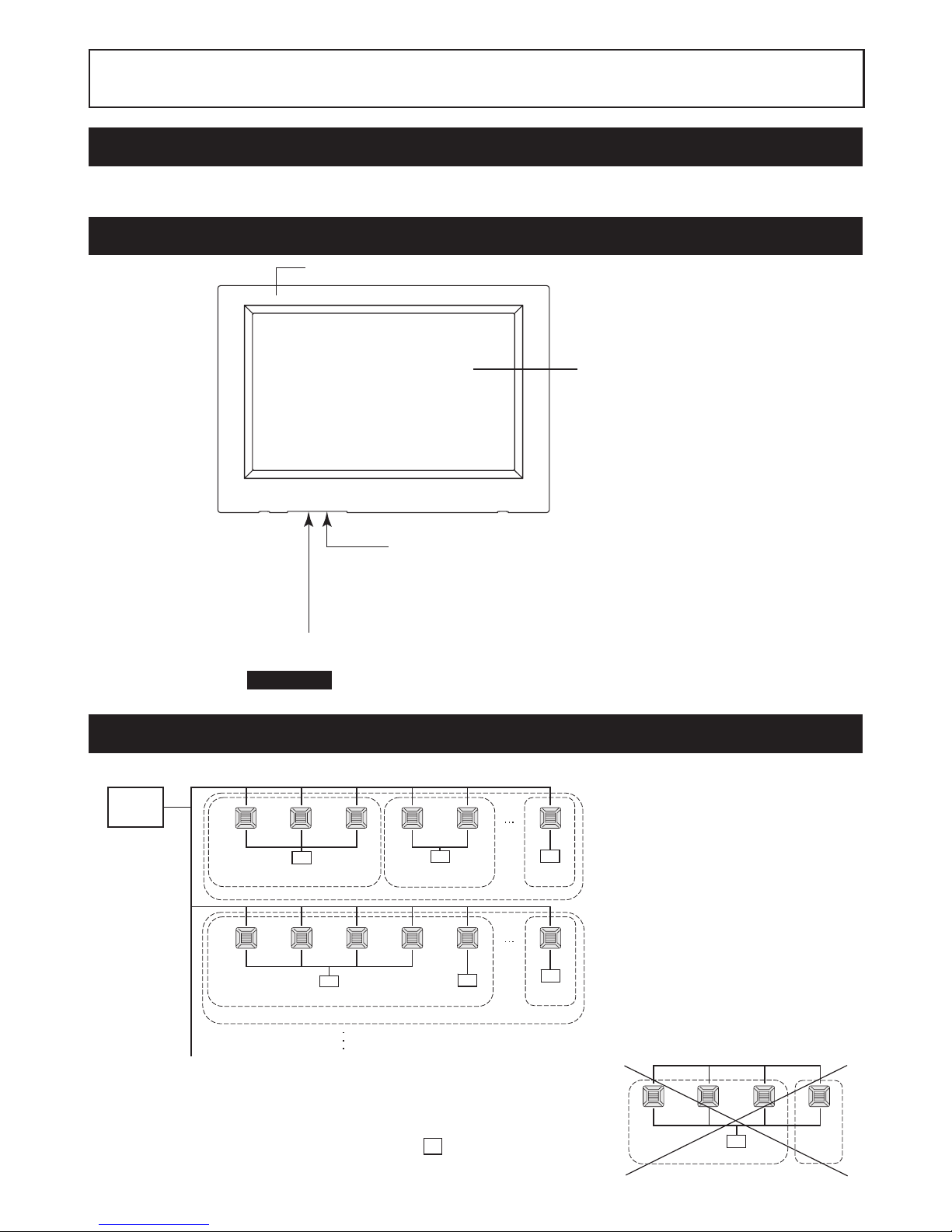
Names and Functions of Parts
Color LCD Display
The screens are displayed here. Operations
are performed by touching it with a fi nger.
USB Memory Slot
Insert the USB memory from the bottom.
Warning
Do not insert any USB device other than the bundled USB memory.
Front Cover
Reset switch
Press the switch that is placed innermost of small hole at the lower side of this
cover, using a straight clip or similar tool.
The screen may be locked depending on the static charge or external noise,
etc, but there is no trouble. In this case, the screen can be returned to normal
display by pressing the reset switch.
Blocks, Groups
[Example of Connections]
Air conditioner
1
Central
control
R
R
R
R
R
R
Air conditioner
16
Air conditioner
2
Air conditioner
17
Air conditioner
4
Air conditioner
19
Group 1
Group Q +1
Group 2
Block 2
Group Q
Group T
Air conditioner
3
Air conditioner
18
Air conditioner
5
Air conditioner
20
Block 1
Air conditioner
P
Air conditioner
R
A maximum of 16 air conditioner can be set up in one group.•
Do not use one remote controller for different groups of air conditioner.•
A maximum of 9 groups can be set up in one block.•
A maximum of 16 blocks can be set up.•
Air conditioner
1
R
Air conditioner
2
Air conditioner
4
Group 1 Group 2
Air conditioner
3
R : Remote controller
Page 6
– 5 –
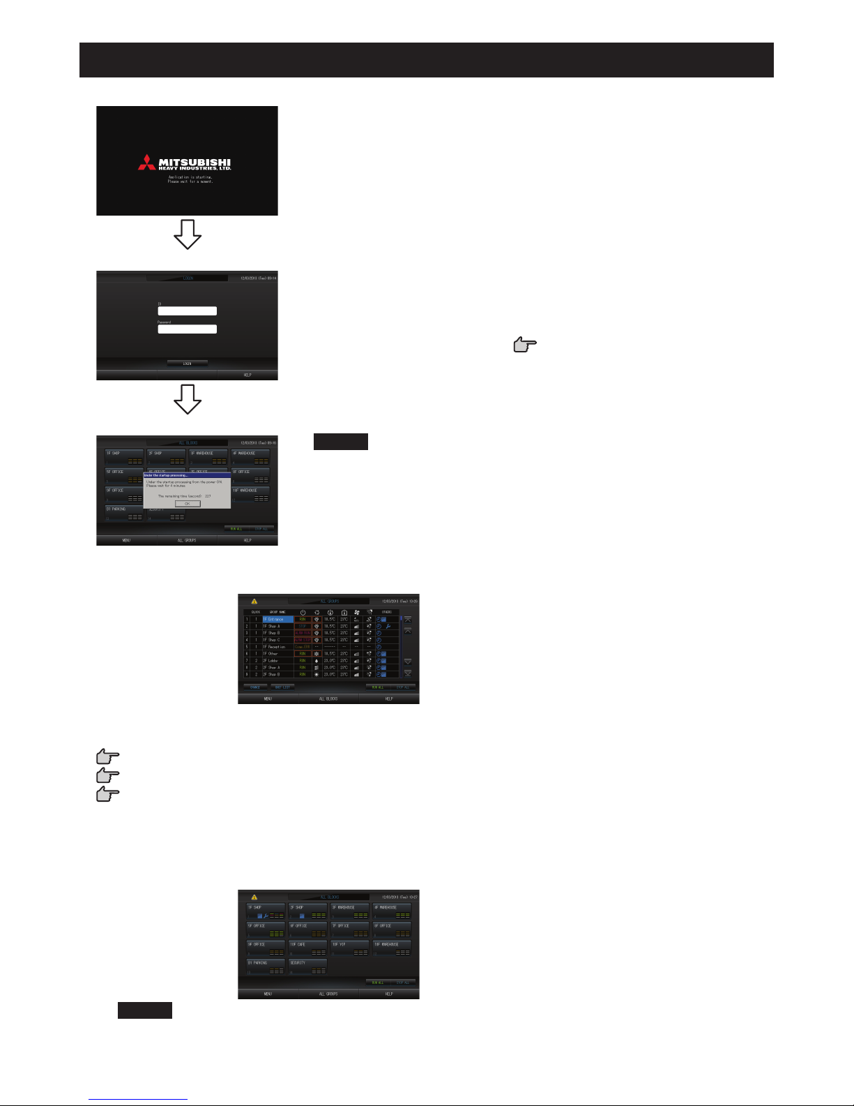
Startup Screen
[Startup Screen]
This screen is displayed at startup.
[Login screen]
The default ID and password are as follows:
Default ID:
Default password:
OPERATOR
123456
After logging in, change the default ID and password to your own.
Changing the ID and password
page 32
[Information Screen]
Note
It is not possible to do any setting when information screen is displayed.
ALL GROUPS Display•
This display appears the fi rst time the unit starts up or when block have not been registered. Make the initial settings
in the following order.
Time & Date Setting page 26
Group Defi nition page 23
Block Defi nition page 25
Once blocks are registered, it is very convenient because the status of all groups can be viewed on a single *
screen.
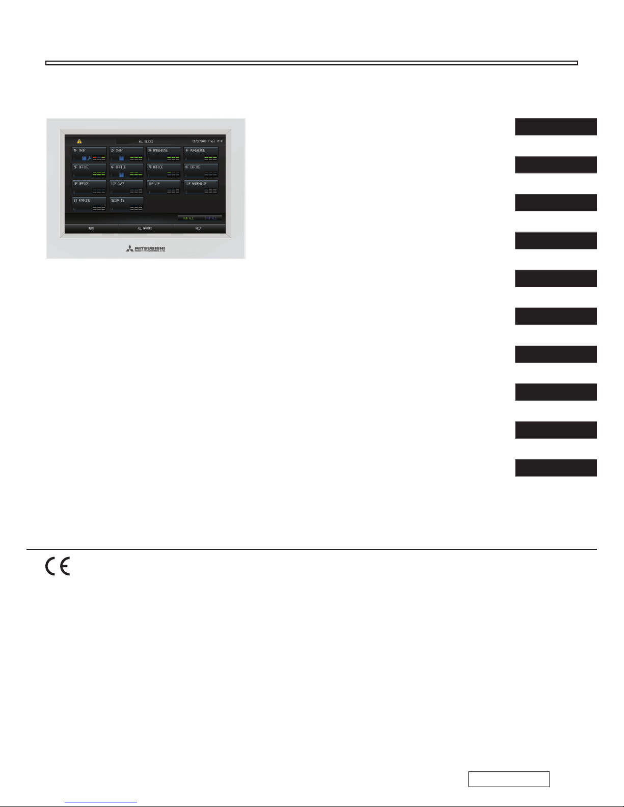
ALL BLOCKS Display•
When blocks have been registered, this display appears.
Note
It may take time for the settings to be read into the unit. Do not perform any operations until all the groups
that have been set are displayed. (This should take only a few minutes.)
Page 7
– 6 –
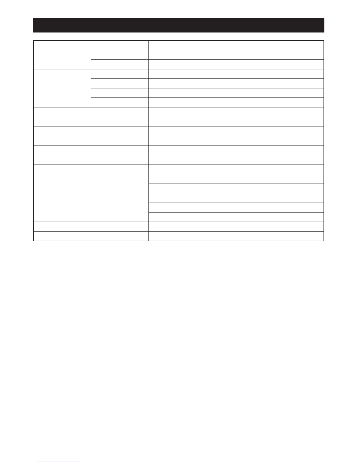
Quick Reference Chart for Operations
Initial settings Date & time Page 26 (Time & Date Setting)
Groups Page 23 (Group Defi nition)
Blocks Page 25 (Block Defi nition)
Viewing status All blocks Page 9 (All Blocks Display)
All groups Page 13 (ALL GROUPS screen)
Each group
Pages 11 & 13 (Group Operation Settings : GROUP(PANEL) & GROUP(LIST) screen)
Each unit Page 21 (Viewing Detailed Unit Information)
Group operation Page 11 (Group Operation Settings)
Multiple groups operation Page 14 (Multiple Groups Operation Settings)
Batch operation Page 15 (Group Batch Operation)
Setting and checking schedules Page 16 (Schedule Settings)
Making calculating settings (SC-SL4-BE only)
Page 22 (Calculating Settings)
Entering numbers and characters Page 27 (Entering Numbers and Characters)
Using convenient functions Page 28 (Display Setting)
Page 29 (Corrections for Power Outages)
Page 29 (Using USB Memory)
Page 33 (System Information)
Page 30 (Operation Time History)
Page 32 (Operator Settings)
Alarm history Page 33 and 42 (Viewing Alarm History)
Further Information Page 33 (Help)
Page 8
– 7 –
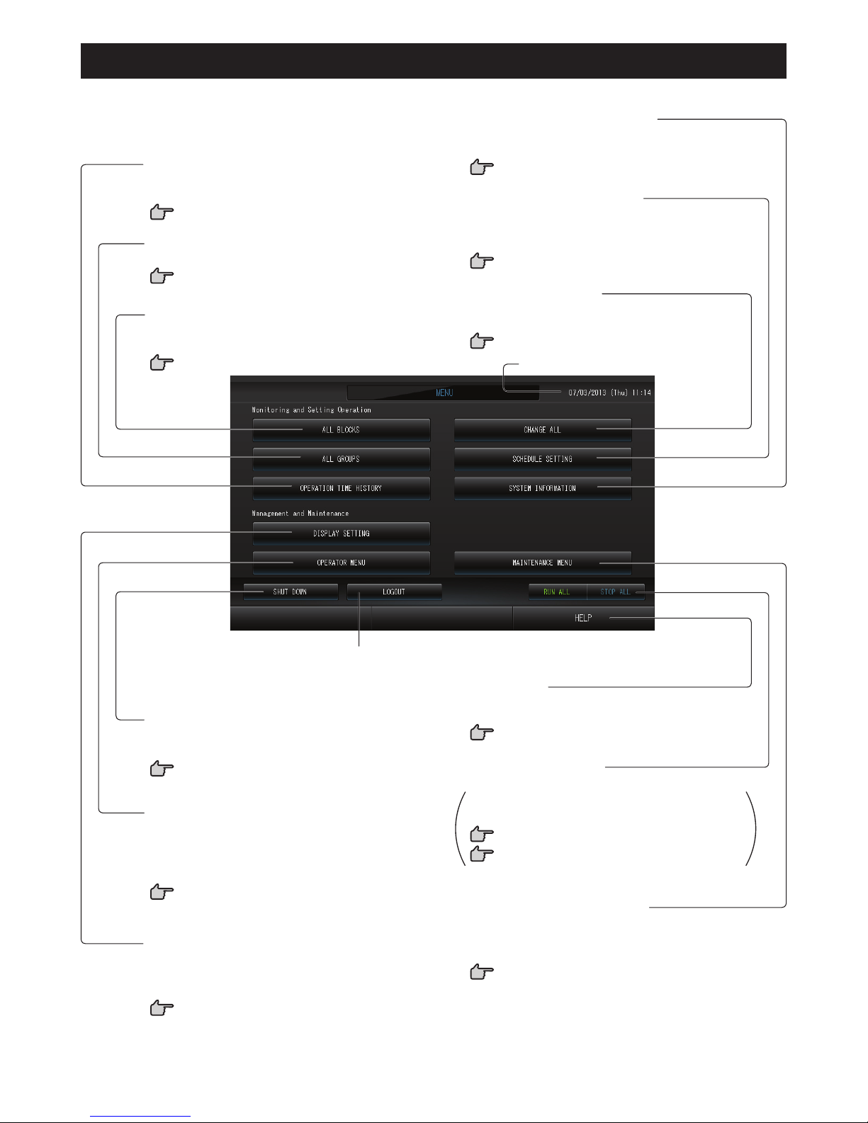
Menu
When the MENU button is pressed, the screen switches to the one shown below.
RUN/STOP ALL button
Stops running for groups set up for batch operation.
Settings can also be made for groups not set up
for batch operation.
page 23 1
page 24 56
CHANGE ALL button
Switches the screen for changing group batch
operation settings.
page 15
MAINTENANCE MENU button
Displays the MAINTENANCE MENU.
This button is displayed only when you have logged in using
the maintenance user ID.
page 36
OPERATION TIME HISTORY button
Displays operation time in graph format for each
group.
page 30
ALL GROUPS button
Displays all group names and status in a list.
page 13
ALL BLOCKS button
Displays a list of the names and status of all blocks
in a panel.
page 9
SHUT DOWN button
When it is known that there will be a power outage,
this button saves the settings.
page 35
SCHEDULE SETTING button
Switches the screen for setting air conditioning
operation schedules.
(If you have not set a group, this button is invalid.)
page 16
OPERATOR MENU button
Switches the screen for making group and block
settings, date and time settings and accounting
settings (SC-SL4-BE only) as well as viewing the
alarm history.
page 8
DISPLAY SETTING button
Sets the brightness of the display and the light-up
period of the backlight, or switches to screen cleaning
mode.
page 28
LOG OUT button.
Return to login screen.
Date and Time display
HELP button
Opens the screen for viewing detailed information
on the display content and operations.
page 33
SYSTEM INFORMATION button
Displays the central control version number and number
of units registered.
page 33
Page 9
– 8 –
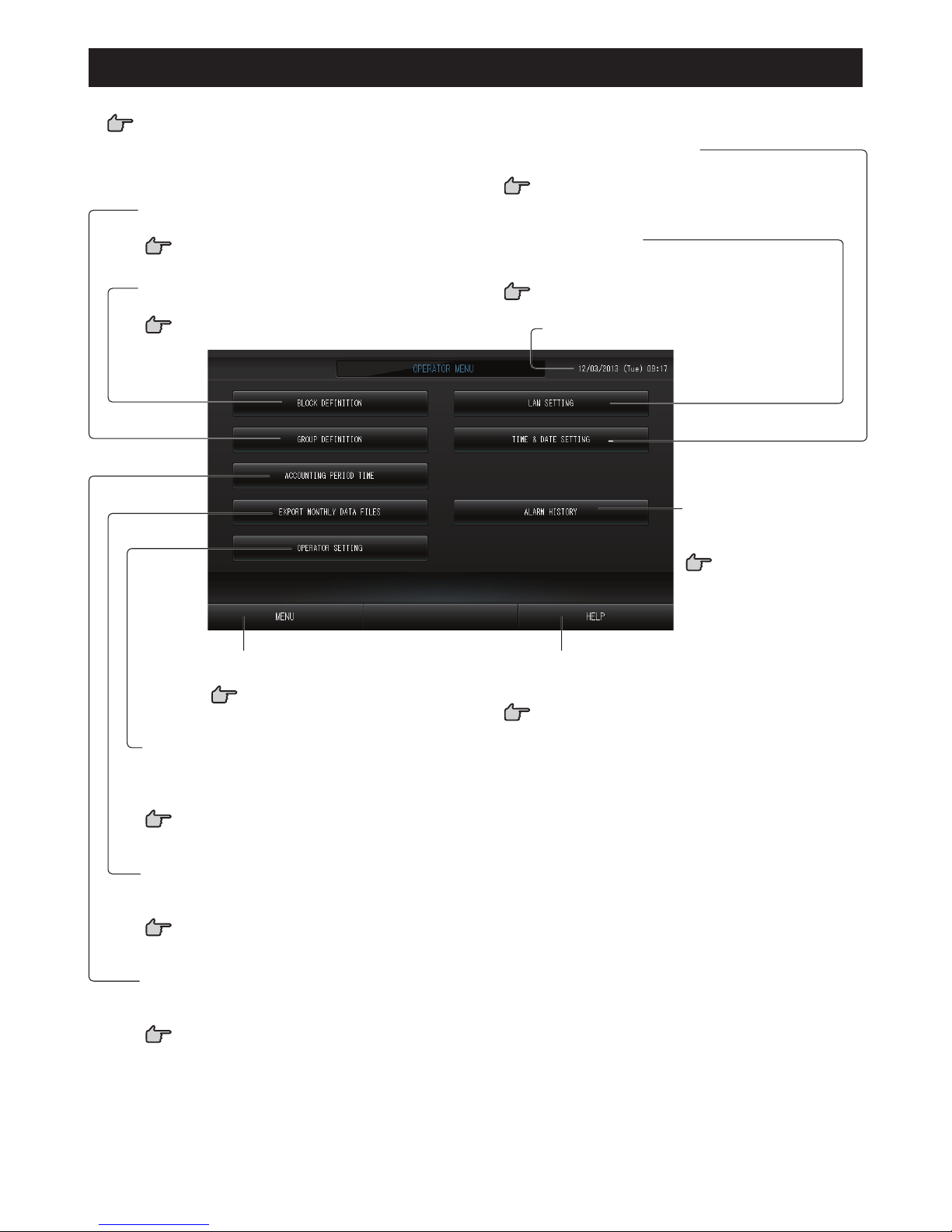
OPERATOR MENU Screen
This is displayed when the OPERATOR MENU button is pressed on the MENU screen.
page 7
TIME & DATE SETTING button
Switches the TIME & DATE SETTING screen.
page 26
EXPORT MONTHLY DATA FILES button
Switches to the screen used to export the accounting
period data and save it on a USB memory device.
page 29
OPERATOR SETTING button
Switches to the screen used to set the operator ID
and password, operator information, and security
lock.
page 32
Date and Time display
HELP button
Opens the screen for viewing detailed information on
the display content and operations.
page 33
MENU button
Returns to the MENU screen.
page 7
ALARM HISTORY button
Displays the Alarm History of
the units.
page 33
GROUP DEFINITION button
Switches the GROUP DEFINITION screen.
page 23
BLOCK DEFINITION button
Switches the BLOCK DEFINITION screen.
page 25
LAN SETTING button
Switches to the screen used to set the IP address,
subnet mask, and gateway address.
page 31
ACCOUNTING PERIOD TIME button
Switches to the screen used to set the start and end
time of the accounting period.
page 22
Page 10
– 9 –
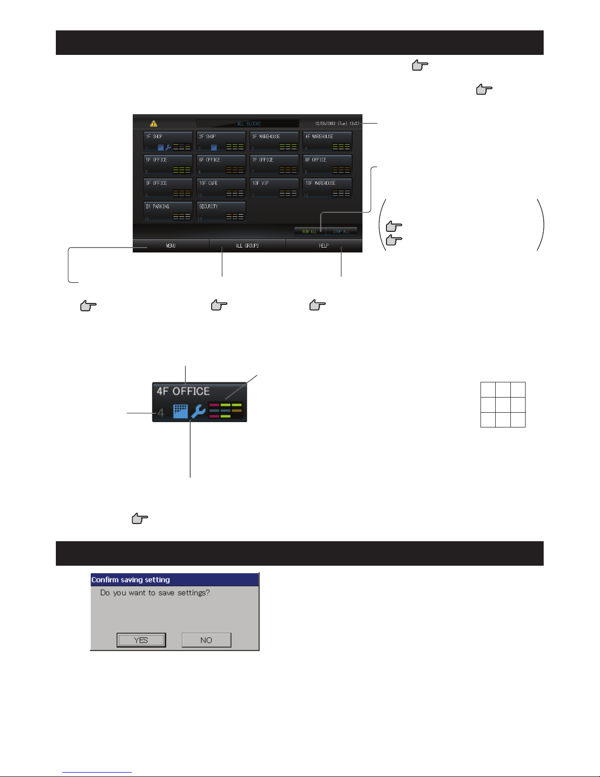
All Blocks Display
This is displayed when the ALL BLOCKS button is pressed on the MENU screen. page 7
The names and the status of all blocks are displayed in the panels. Unestablished blocks or blocks without any
groups are not displayed. If a block button is pressed, the GROUP (PANEL) screen is displayed.
page 11
RUN/STOP ALL button
Stops running for groups set up for batch
operation.
Settings can also be made for groups
not set up for batch operation.
page 23 1
page 24 56
Date and Time display
MENU button
Returns to the MENU screen.
page 7
HELP button
Opens the Help.
page 33
ALL GROUPS button
Displays all groups.
page 13
Individual Block Displays•
Each group status display
The colors 1 – 9 show the status of the groups. As shown
in the right fi gure, it is arranged from small group number.
The colors have the following signifi cance.
(Green) Running
(Blue) Stopped
(Red) Malfunction
(Yellow) Communication error
(Gray) No groups
Block name
Block number
Filter Sign and Maintenance Indicator
Displayed when at least one group needs the cleaning of the
fi lters or maintenance.
page 10
1 2 3
4 5 6
7 8 9
Changeover Confi rmation Screen
This is a screen for confi rming the changes to various
settings. The text displayed varies according to the screen
called up, but the operation is as follows.
Press the Yes button to save the settings and to exit. Press
the No button to exit without saving your settings.
Page 11
– 10 –
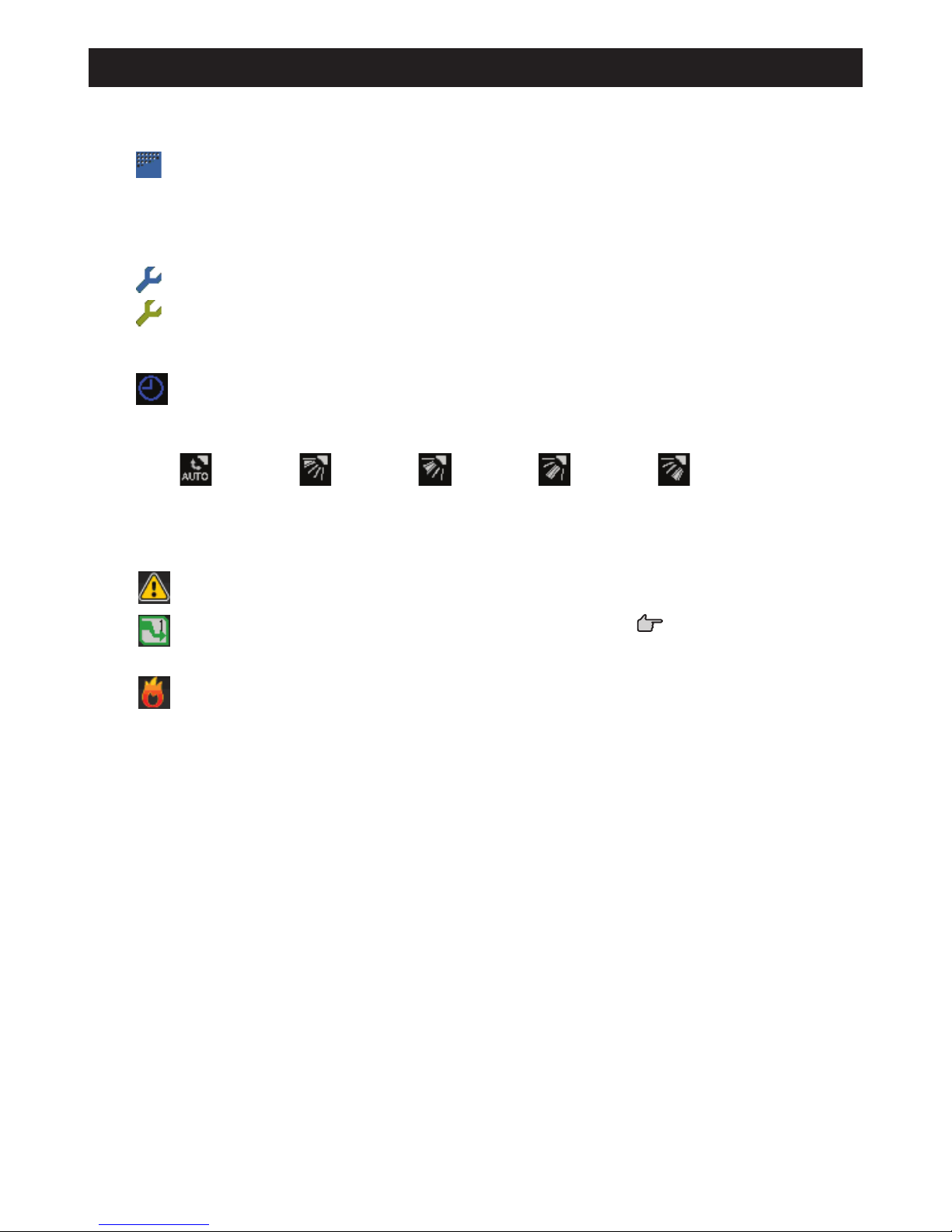
Icons
Filter sign(1)
If at least one air conditioner in a block or group needs fi lter maintenance, this indicator lights up. When this
happens, clean the fi lters.
Maintenance Indicator(2)
When the maintenance indicator is lit for at least one air conditioner in a block or group, the maintenance
indicator is displayed. If the maintenance indicators are off on all units, the maintenance indicator turns off.
Contact your dealer if this indicator is on.
(Gray) Inspection, Inspection 1, Inspection 2
(Yellow) Backup operation (Inspection 3)
Scheduling(3)
This shows the groups that are the targets of the current day’s schedule.
Air direction(4)
This shows the status of louver operation.
Swinging
(AUTO)
Position 1
(STOP 1)
Position 2
(STOP 2)
Position 3
(STOP 3)
Position 4
(STOP 4)
Unit states(5)
The unit status is shown by fi gures.
Error stop (One or more units have been stopped because of malfunction.)
Please contact your dealer.
Demand (The external signal is inputted to the demand terminal.
page 24)
The target unit will switch to fan mode and remote controller operations are prohibited. When the external
signal is cancelled, the setting will return.
Emergency stop (The external signal is inputted to the emergency stop terminal.)
All units stop and operations are prohibited. When the emergency stop signal is cancelled, the remote
controller lock/unlock setting will return but the units remain stopped.
Page 12
– 11 –
Operation
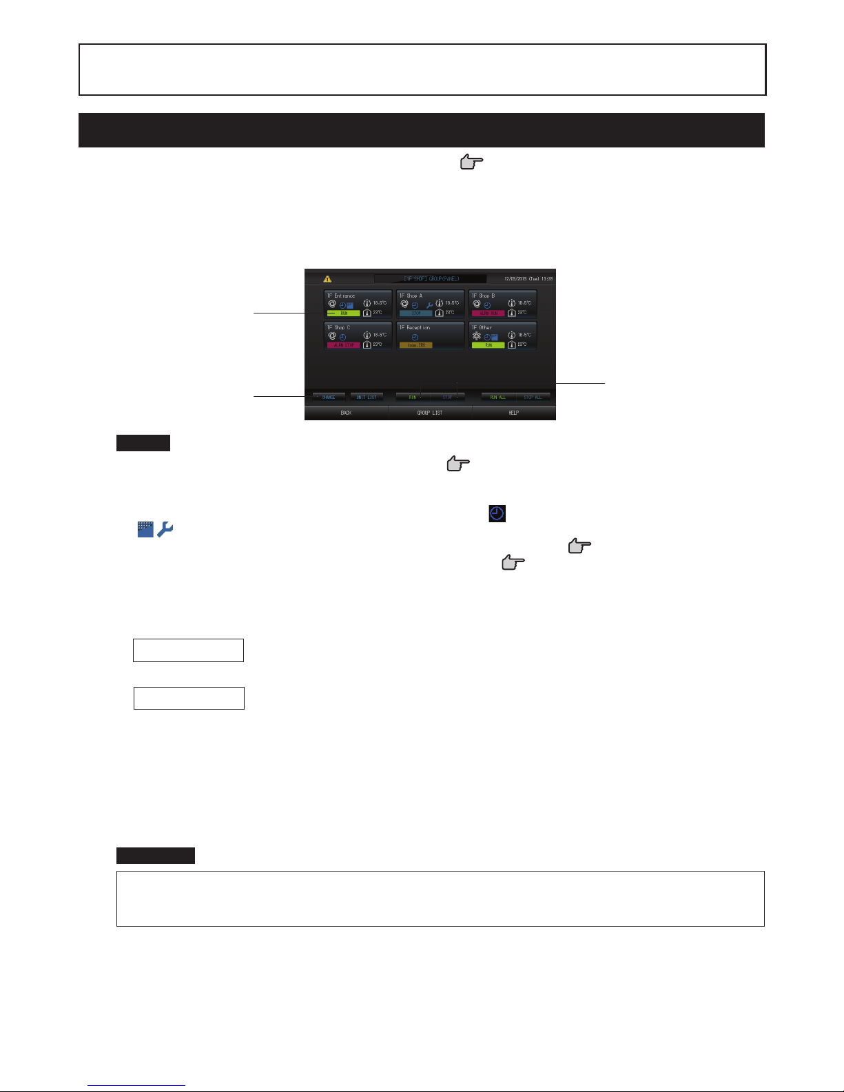
Group Operation Settings (Monitor Group Status)
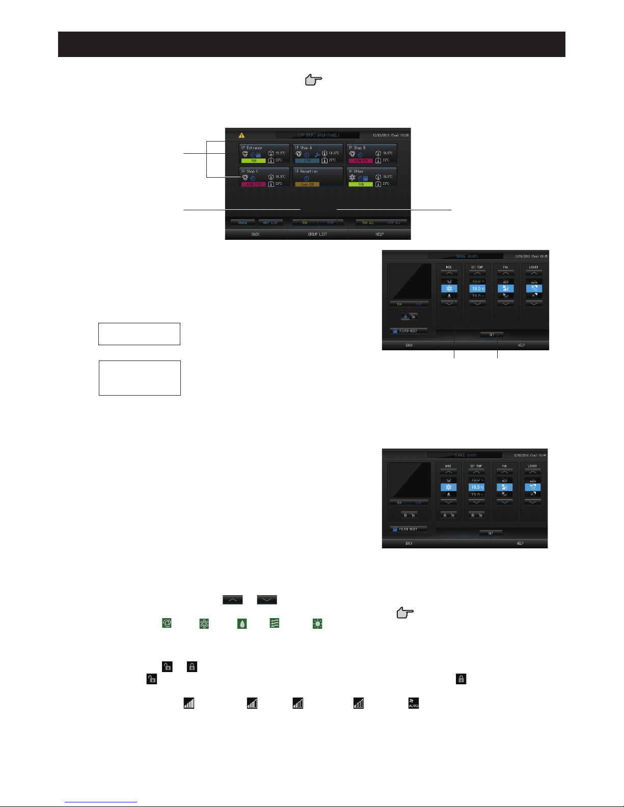
Press the ALL BLOCKS button on the MENU screen.1. page 7
Press the block you wish to set or monitor. 2.
The GROUP (PANEL) screen is displayed.
The group name, status, fi lter sign, maintenance, scheduling, temperature settings and room temperature can
be observed.
[GROUP (PANEL) screen]
3
4
4
Note
See Icons for the signifi cance of the icon displays. •
page 10
The running status, operating mode, temperature settings and room temperature are shown for the •
representative unit. When all units are stopped, stopped status is shown.
Groups that have the current day’s schedule settings show •
.
• being displayed means that these are lit for one or more units.
If the GROUP LIST button is pressed, the GROUP (LIST) is displayed. •
page 13
To display the units in a group, press the UNIT LIST button. •
page 21
<When running and stopping each group>
Press the panel of the group for which settings are to be made. 3.
The panel frame turns blue.
4. To run units Press the RUN button, and press the Yes button on the confi rmation screen.
The selected group starts running.
To stop units Press the STOP button, and press the Yes button on the confi rmation screen.
The selected group stops running.
When you do not want to set, press the No button.
<When making settings and changes on each group>
Press the panel of the group for which settings or changes are to be made. 3.
The panel frame turns blue.
Press the CHANGE button.4.
The screen for CHANGE screen is displayed. When the screen changes, no items are selected (the temperature
setting is blank). Set only the items that are to be set or changed.
Attention
A static electric discharge to the unit could cause a break-down.
Before performing operations, touch a grounded metal object and discharge any static electricity.
Page 13
– 12 –
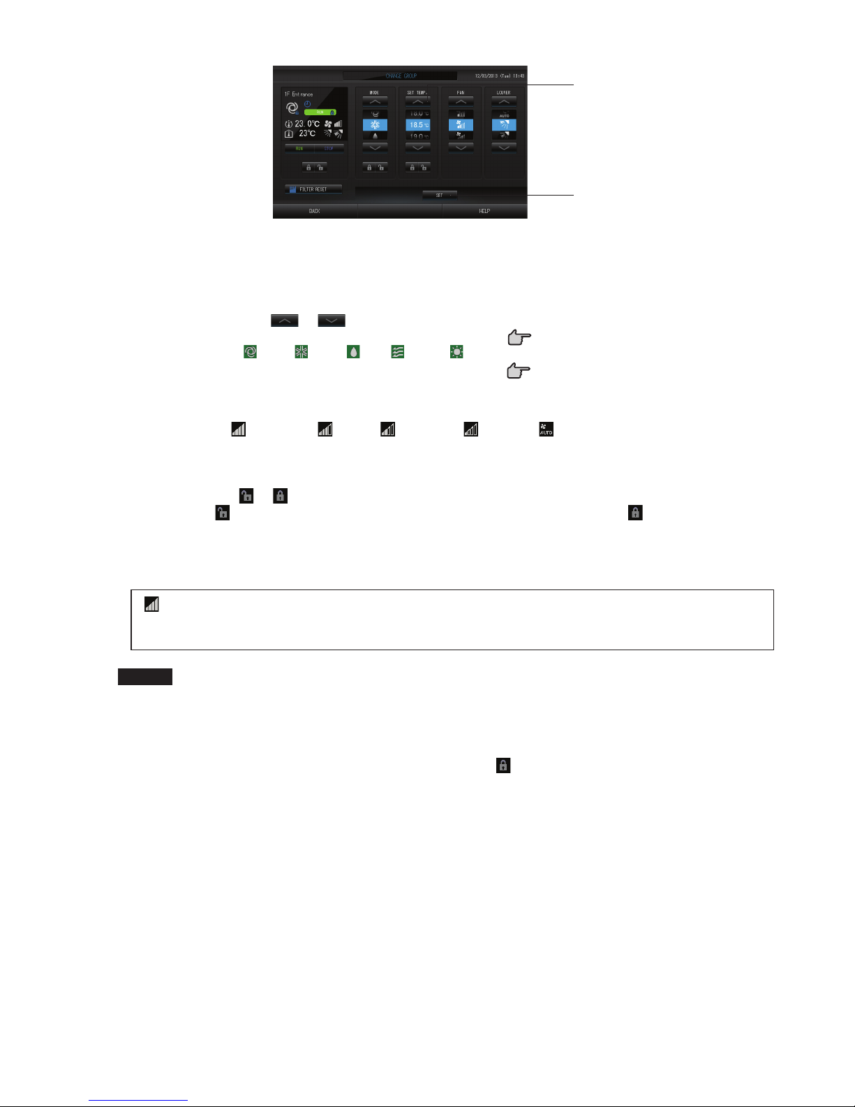
[CHANGE screen]
6
5
Press the button for the item to set or change. 5.
Run/Stop: Press the RUN or STOP button. ·
When the RUN button is selected, the operation starts, and when the STOP button is selected,
the operation stops.
SET TEMP.: Press •
or .
Set a temperature between 18°C and 30°C.
page 39
MODE: select ·
Auto, Cool, Dry, Fan or Heat by pressing the button.
Auto Mode can be valid in the MAINTENANCE MENU. *
page 39
This function can be applied to the indoor units, which are the cooling/heating free multi KXR, single ·
split PAC.
FAN: Select ·
(Powerful), (High), (Medium), (Low), or (AUTO), and press the button.
When using powerful mode, valid Powerful Fan on the MAINTENANCE MENU.*
When using automatic mode, valid the AUTO Fan on the MAINTENANCE MENU.*
Air direction: Select Auto, stop 1, stop 2, stop 3 or stop 4 and press the button. ·
LOCK: Press ·
or .
If
is pressed, remote controller operations are permitted, and if is pressed, they are
prohibited.
FILTER RESET: If the reset button is pressed, the fi lter sign turns off. ·
Press the SET button. Press the Yes button on the confi rmation screen. 6.
When you do not want to set or change, press the No button.
(Powerful mode)
Operates with the maximum fan speed.
It is suitable for heating or cooling the entire room thoroughly.
Note
If the BACK button is pressed, it returns to the previous screen. •
If individual lock/unlock is valid in the MAINTENANCE MENU, it is possible to set the remote controller •
operations to permit or prohibit each item such as run/stop, mode and temperature setting.
When individual lock/unlock are valid in the MAINTENANCE MENU, remote controller operations are •
prohibited if run/stop, mode and temperature setting are all
. (Some functions, such as reset of the fi lter
sign have been permitted.)
Page 14

– 13 –
The following method can also be used to set and ■
change operations on each group.
When making settings or changes in the GROUP ►
(LIST) screen
Press the GROUP LIST button in the GROUP (PANEL) 1.
screen.
page 11
The GROUP (LIST) screen is displayed.
[GROUP (LIST) screen]
2
3
Press the name of the group for which settings or changes are to be made. 2.
The group name is reverse highlighted, press the
or button.
Press the CHANGE button. 3.
The screen for CHANGE screen is displayed. Make the settings or changes.
page 12
Note
If the BACK button is pressed, it returns to the previous screen. •
Run is indicated when at least one unit is running. Malfunctions are indicated when at least one unit is not •
in good condition. Stop is indicated when all the units have stopped.
icon is displayed when at least one unit needs cleaning fi lter.
icon is displayed when at least one unit needs maintanance.
Operating mode, temperature setting, room temperature, fan speed and air direction show the state of the
representative unit.
The ones which are surrounded by red frames are the items which operations from the remote controller •
are prohibited in the group settings.
If the GROUP PANEL button is pressed, the GROUP (PANEL) screen is displayed.
•
page 11
When making settings or changes in the ALL GROUPS screen ►
Press the ALL GROUPS button on the MENU.1.
page 7
Press the name for the group to set or change. 2.
[ALL GROUPS screen]
2
3
The group name is reverse highlighted.
When the screen switches, the previously selected group name is selected. To change the page, press the
or button.
Press the CHANGE button.3.
The screen for CHANGE screen is displayed. Make the settings or changes.
page 12
Note
To display the units in a group, press the UNIT LIST button. •
page 21
To show all blocks, press the ALL BLOCKS button. •
page 9
The ones which are surrounded by red frames are the items which operations from the remote controller •
are prohibited in the group settings.
If the MENU button is pressed, the MENU screen is displayed. •
page 7
Page 15
– 14 –
Multiple Groups Operation Settings
This section shows how to operate multiple groups in the same block.
Press the ALL BLOCKS button on the MENU.1.
page 7
Press the block you wish to set. 2.
The GROUP (PANEL) screen is displayed.
[GROUP (PANEL) screen]
3
44
<When running and stopping multiple groups>
Press the panels of the groups for which settings are to be 3.
made (multiple groups can be selected).
The panel frame turns blue.
When you want to cancel, please press the panel of the group
again.
4.
To run units
Press the RUN button, and press the Yes
button on the confi rmation screen.
The selected group starts running.
To stop units
Press the STOP button, and press
the Yes button on the confirmation
screen.
The selected group stops running.
When you do not want to set, press the No button.
56
<When making settings and changes on multiple groups>
Press the panels of the groups for which settings or changes 3.
are to be made (multiple groups can be selected).
The panel frame turns blue.
When you want to cancel, please press the panel of the group
again.
Press the CHANGE button.4.
The screen to change groups is displayed. When the screen
changes, no items are selected (the temperature setting is blank).
Set only the items that are to be set or changed
Press the button for the item to set or change. 5.
Run/Stop: Press the RUN or STOP button. ·
With the RUN button, running starts, and with the
STOP button, running stops.
[Individual lock/unlock settings valid in Function
Setting]
This function can be applied to the indoor units,
which are the model KXE4 or later, and to the
remote controller, which is the model RC-E1
or later.
Temperature setting: Press • or .
Set a temperature between 18°C and 30°C.
page 39
Mode: Select ·
Auto, Cool, Dry, Fan or Heat by pressing the button.
When using Auto Mode, valid AUTO on the MAINTENANCE MENU.*
The Auto Mode can be valid for the cooling/heating free multi KXR, single split PAC.
LOCK: Press ·
or .
If
is pressed, remote controller operations are permitted, and if is pressed, they are
prohibited.
Fan speed: Select ·
(Powerful), (High), (Medium), (Low), or (AUTO), and press the button.
When using powerful mode, valid the Powerful Fan on the MAINTENANCE MENU.*
When using automatic mode, valid the AUTO Fan on the MAINTENANCE MENU.*
Air direction: select Auto, stop 1, stop 2, stop 3 or stop 4 and press the button. ·
FILTER RESET: If the reset button is pressed, the fi lter sign turns off. ·
Page 16

– 15 –
Press the SET button. Press the Yes button on the confi rmation screen. 6.
When you do not want to set, press the No button.
Note
If the BACK button is pressed, it returns to the previous screen. •
If individual lock/unlock is valid in the MAINTENANCE MENU, it is possible to set the remote controller •
operations to permit or prohibit each item such as run/stop, mode and temperature setting.
When individual lock/unlock are valid in the MAINTENANCE MENU, remote controller operations are •
prohibited if run/stop, mode and temperature setting are all
. (Some functions, such as reset of the fi lter
sign have been permitted.)
Group Batch Operation
This section shows how to set or change the detailed setting of Batch Operation.
Set the groups for batch operation in advance.
page 231, 2456
Press the CHANGE ALL button on the MENU screen.1.
page 7
The CHANGE ALL screen is displayed.
2
3
[Individual lock/unlock settings valid in
MAINTENANCE MENU]
This function can be applied to the indoor units,
which are the model KXE4 or later, and to the
remote controller, which is the model RC-E1
or later.
Note
When the screen changes, no items are selected (the temperature setting is blank). Set only the items that
are to be set or changed.
Press the button for item to set or change. 2.
Run/Stop: Press the RUN or STOP button. ·
When the RUN button, running starts, and when the STOP button, running stops.
Temperature setting: Press •
or .
Set a temperature between 18°C and 30°C.
page 39
Mode: Select ·
Auto, Cool, Dry, Fan or Heat by pressing the button.
When using Auto Mode, valid AUTO on the MAINTENANCE MENU. *
page 36
The Auto Mode can be valid for the cooling/heating free multi KXR, GHP-R series or later and single split
PAC.
LOCK: Press ·
or .
If
is pressed, remote controller operations are permitted, and if is pressed, they are
prohibited.
Fan speed: Select ·
(Powerful), (High), (Medium), (Low), or (AUTO), and press the button.
When using powerful mode, valid the Powerful Fan on the MAINTENANCE MENU.*
When using automatic mode, valid the AUTO Fan on the MAINTENANCE MENU.*
Air direction: select Auto, stop 1, stop 2, stop 3 or stop 4 and press the button. ·
FILTER RESET: If the reset button is pressed, the fi lter sign turns off. ·
Press the SET button. Press the Yes button on the confi rmation screen. 3.
When you do not want to set, press the No button.
Note
If the BACK button is pressed, it returns to the previous screen.•
If individual lock/unlock is valid in the MAINTENANCE MENU, it is possible to set the remote controller •
operations to permit or prohibit each item such as run/stop, mode and temperature setting.
When individual lock/unlock are valid in the MAINTENANCE MENU, remote controller operations are •
prohibited if run/stop, mode and temperature setting are all
. (Some functions such as reset of the fi lter
sign have been permitted.)
Page 17

– 16 –
Schedule Settings
Operating schedules can be set in group units. Sixteen schedules per day can be registered for operating time (in
minutes), run/stop, mode, prohibiting remote controller operations and temperature setting.
Set the detailed daily schedule (weekday, holiday, special 1, special 2) in advance.
page 17
Press the SCHEDULE SETTING button on the MENU screen. 1.
page 7
The SCHEDULE SETTING screen is displayed.
2
Setting the current day’s schedule ■
The operating schedule for the current day is set on each group.
Press the TODAY’S SCHEDULE button on the SCHEDULE SETTING screen. 2.
3
5
4
6
Press the group name.3.
Select the group on the Select Group screen.
page 19
<When setting a schedule for the current day>
Press the item to be changed on the list.4.
When “Time”, “Lock” or “SET TEMP.” cell are pressed, a detailed setting screen for each item is indicated.
page 19, 20
Change the “RUN/STOP” or “MODE” settings by pressing the appropriate item.
To change the page, press the
or button.
<When rewriting the schedule displayed for the current day to detailed daily schedule>
Select the detailed daily schedule such as WEEKDAY (green), HOLIDAY (red), SPECIAL1 (blue) or 5.
SPECIAL2 (yellow) button and press it.
Note
Set the operating schedule for the detailed daily schedule in advance. page 17
Press the SET button. Press the Yes button on the confi rmation screen. 6.
When the CLEAR button is pressed, the selections are cleared.
Note
Press the COPY button when copying the schedule between groups. • page 20
Page 18

– 17 –
Setting a detailed daily schedule ■
The detailed daily schedule is set for each group.
The schedule indicates WEEKDAY, HOLIDAY, SPECIAL1, SPECIAL2, and the operation can be set for
each group.
Press the DETAILED DAILY SCHEDULE button on the 2. SCHEDULE SETTING screen.
3
4
5
6
Press the group name.3.
Select the group on the Group Select screen.
page 19
Select the detailed daily schedule such as WEEKDAY (green), HOLIDAY (red), SPECIAL1 (blue) or 4.
SPECIAL2 (yellow) button and press it.
Press the item to be changed on the list.5.
When “Time”, “Lock” or “Temperature setting” buttons are pressed, a detailed setting screen for each item is
indicated.
page 19, 20
Change the “Run/Stop” or “MODE” setting by pressing the appropriate item.
To change the page, press the
or button.
Press the SET button. Press the Yes button on the confi rmation screen. 6.
When the CLEAR button is pressed, the selections are cleared.
Note
Press the COPY button when copying the schedule between groups. • page 20
Setting a yearly schedule ■
A yearly operating schedule is set on each group.
Press the YEARLY SCHEDULE button on the SCHEDULE SETTING screen. 2.
3
4
5
6
Press the group name.3.
Select the group on the Select Group screen.
page 19
Select the detailed daily schedule such as WEEKDAY (green), HOLIDAY (red), SPECIAL1 (blue) or 4.
SPECIAL2 (yellow) button and press it.
Note
Set the detailed daily schedule in advance. Noted above (Setting a detailed daily schedule)
Press the date (multiple dates can be selected).5.
The detailed daily schedule which you choose is applied to that day. However, the current day and the dates
which have elapsed can not be selected. Press the
or button to change the month.
Note
If the DEFAULT button is pressed, Saturday and Sunday are set as holidays and the others are set as
weekdays.
Page 19

– 18 –
Press the SET button. Press the Yes button on the confi rmation screen.6.
When you do not want to set, press the No button.
Pressing the COPY button brings up the Copy Schedule screen when copying between groups.•
page 20
Season Settings ■
Confi gure the mode setting when you have selected “SEASON” mode in the schedule settings.
Selecting “SEASON” mode valid you to subsequently change the operating mode and temperature setting
collectively at the turn of each season.
Press the SEASON SETTING button on the SCHEDULE SETTING screen.1.
3
2
4
Press the group name.2.
Select the group on the Group Select screen.
Select mode3.
COOL button:
When COOL is selected, set the operating mode of the group, for which “SEASON” is selected in the schedule,
to cooling, and you can set the temperature.
page 39
DRY button:
When DRY is selected, set the operating mode of the group, for which “SEASON” is selected in the schedule,
to drying, and you can set the temperature.
page 39
HEAT button:
When HEAT is selected, set the operating mode of the group, for which “SEASON” is selected in the schedule,
to heating, and you can set the temperature.
page 39
Press the SET button. Press the Yes button on the confi rmation screen.4.
If you do not want to make the setting, press the No button.
Note
Copy button:
Pressing the Copy button copies the season settings of the other group.
Page 20

– 19 –
Various screens ■
[Select Group screen]
1
2
Press the group name to be selected. 1.
The selected group name is reverse highlighted.
To change the page, press the PREV or NEXT button.
Press the OK button.2.
The selected group can be set.
When you do not want to set, press the CANCEL button. It returns to the previous screen.
[Schedule Time Setting screen]
1
2
Pressing 1. ▲▼ changes the hour and minutes (24 hour clock display).
Press the OK button.2.
The time is changed and the screen closes. Press the CANCEL button to cancel the change.
Pressing the CLEAR button clears the currently entered values and makes the entry empty.
[Remote Controller Lock/Unlock screen]
This is used to allow or prohibit remote controller
operations.
[Individual lock/unlock settings valid in MAINTENANCE
MENU]
1
2
21
Press the button of the items which are to be prohibited from the remote controller operation (multiple 1.
items can be selected).
Press the OK button.2.
The prohibited item changes and the screen closes.
Press the CANCEL button to cancel the change.
If the CLEAR button is pressed, the selected item is deselected.
Page 21

– 20 –
[Schedule Temperature Setting screen]
1
2
Pressing 1. ▲▼ changes the temperature. page 39
Press the OK button.2.
The temperature changes and the screen closes.
Press the CANCEL button to cancel the change.
Pressing the CLEAR button clears the currently entered values and makes the entry empty.
[Copy Schedule screen]
Select the groups that apply the chosen schedule.
1
2
Press the group name to be selected (multiple groups can be selected).1.
To change the page, press the PREV or NEXT button.
To select all groups, press the ALL GROUPS button. If you will cancel selecting all groups, press the ALL
GROUPS button again.
Press the COPY button. Press the Yes button on the confi rmation screen. 2.
The schedule of the group chosen on the screen is pasted to the groups checked in the list. When you do not
want to make the setting, press the No button.
Note
This is cancelled if the selected group is pressed once more. •
If the CANCEL button is pressed, it returns to the previous screen. •
Page 22

– 21 –
Viewing Detailed Unit Information
The unit numbers and status of each group can be observed.
Press the UNIT LIST button in the ALL GROUPS screen (1.
page 13) or if the UNIT LIST button is
pressed in the GROUP (PANEL) or GROUP (LIST) screen (
page 11, 13).
The units in the group are displayed.
To change the page, press the
or button.
Note
If the BACK button is pressed, it returns to the previous screen. •
UNIT No. display may differ from the fi guration. (Same as every other screen)•
Display is changed according to the SL communication system (
page 37).
Previous SL) [3-04] New SL) [005]
SuperLink No.
unit address unit address
Page 23

– 22 –
Calculating Settings (SC-SL4-BE only)
UNIT DEFINITION1
Set the unit defi nition on the MAINTENANCE MENU.
page 36
If you want to change the initial settings confi gured at the time of installation, contact your dealer.
Setting the period for calculation2
You can divide a day into two periods for calculation.
If it is not necessary to divide the period into two parts, you can set the period time for 0:00 - 24:00.
Press the ACCOUNTING PERIOD TIME button on the OPERATOR MENU screen. 1.
page 8
2
3
Press the hour or minute buttons for the start time or the end time.2.
Input the time.
Press the SET button. Press the Yes button on the confi rmation screen.3.
When you do not want to set, press the No button.
If the BACK button is pressed, it returns to the OPERATOR MENU screen.
Caution
The energy consumption calculated by this unit does not conform to OIML, and there are no
guarantees concerning the results of the calculations.
This unit calculates only energy consumption distribution (gas, electric power). You need to calculate
the air-conditioning rates.
The calculating data for twelve months are saved.
See page 29 (Using USB Memory) for the method for extracting calculating data.
Page 24

– 23 –
Group Defi nition
Selecting the groups to register and display the registered units1
[Initial GROUP DEFINITION screen]
Press the OPERATOR MENU button on the MENU.1.
page 7
Press the GROUP DEFINITION button on the OPERATOR 2.
MENU screen. page 8
The GROUP DEFINITION screen is displayed.
3
4
Initial GROUP DEFINITION screen may vary
according to the SL communication system.
(Example for previous SL setting)
1- 00
SuperLink No. Unit address
(Example for new SL setting)
005
Unit address
One indoor unit is registered with one group in
advance on the initial screen.
When registering the indoor unit to other groups,
register it with other group after deleting it
from the group, and moving it in the list of ALL
UNITS.
Press a group name.3.
When adding a group, press an empty group name area. When changing the settings for a registered group,
press that group name. The selected group is reverse highlighted. To change the page, press the
or
button.
Press the DETAIL button. 4.
The GROUP DEFINITION DETAILS screen is displayed.
5
11
12
9
14
6
13
8 10
7
Registering and changing the Group Name being set2
Press the Group Name.5.
Enter the name for the group.
page 27
Adding and deleting units making up the group3
<When adding units>
6. or directly press a unit name to select the unit from the list of All Units.
To change the page, press the
button or the button.
Press the ADD button. 7.
The selected unit is added to the list of Unit Entry and deleted from the list of All Unit.
<When deleting units>
Directly press a unit name to select the unit from the list of Unit Entry.8.
Press the DEL button. 9.
The selected unit is deleted from the list of Unit Entry and moved to the list of All Units.
Page 25

– 24 –
Setting the representative unit and demand4
Directly press a unit name to select the unit from the list of Unit Entry.10.
Press the Rep. cell. 11.
That unit is set as the representative unit, and an asterisk is placed to the left of its name in the display.
Representative unit: unit for which the status is shown when the group is displayed ·
Press the Demand cell.12.
That unit is set as for the demand operation, and a mark such as D1, D2, or D3 is placed to the right of its
name.
Demand: · A unit that shifts its set temperature by 2 deg C or switches to fan mode when there is an
external demand input, and then cannot be operated from the remote controller.
Note
By the demand input, it is possible to save on power costs by reducing the power consumption.
Operation of the unit when demand input is released, is conformed to nearest schedule before release time
of the day.
page 43
In case schedule of the day is not set, the unit is for the operation mode and remote controller permission/
prohibition setting which is just before the demand input.
Up to three demand levels can be set. In level 1, the set temperature of the air conditioner set to D1 shifts by
2 deg C (+2 deg C in cooling or dry mode or -2 deg C in heating mode). In level 2, the units set to D1 or D2
switch to fan mode. In level 3, the units set to D1, D2, or D3 switch to fan mode.
To use the demand control, a demand signal must be inputted. For more information, contact your installation *
contractor or dealer.
Setting and unsetting batch operation for the group5
Press the VALID or INVALID button.13.
VALID: group set up for batch operation ·
INVALID: group not set up for batch operation ·
Saving the settings6
Press the SET button. Press the Yes button on the confi rmation screen. 14.
The group settings are saved. When you do not want to save the settings, press the No button.
Note
1 to 16 units can be registered in a group. •
When you will delete all group defi nition, press the DELETE ALL SETTING button and enter your password •
Press the Yes button on the confi rmation screen.
Caution
All schedule settings are deleted too.
Attention
If an unconnected air conditioner is registered in a group, a “Communication error” may occur, affecting
communication of the whole system and causing an unintended operation to be performed. Do not register
unconnected units in a group.
Also note that, at the initial setting, one air conditioner is registered in one group in advance. If the unit is
an unconnected unit, it must be deleted individually. It is recommended that, when registering new groups,
you press the “DELETE ALL GROUPS” button to delete all groups once, and then register groups for
connected units. That certainly is an easier way to confi gure the settings as well as a sure method to prevent
communication errors.
Page 26

– 25 –
Block Defi nition
Attention
Register the group beforehand.
page 23
Selecting the blocks to defi ne and displaying the registered groups1
Press the OPERATOR MENU button on the MENU screen.1.
page 7
Press the BLOCK DEFINITION button on the OPERATOR MENU screen.2.
page 8
The BLOCK DEFINITION screen is displayed.
3
4
[Initial BLOCK DEFINITION screen]
When defi ning a new block, the block names and
registered groups are empty.
Select a block name.3.
When adding a block, select an empty BLOCK NAME cell. When changing the settings for a registered block,
press that BLOCK NAME. The selected block is reverse highlighted. To change the page, press the
or
button.
Press the DETAIL button.4.
The BLOCK DEFINITION DETAILS screen is displayed.
7
9
6
8
10
5
[
Initial BLOCK DEFINITION DETAILS screen
]
When defi ning a new block, the block names and
group entry area are empty.
Registering and changing the Block Name being set2
Press the BLOCK NAME button.5.
Enter the name for the block.
page 27
Page 27

– 26 –
Adding and deleting groups registered in a block3
<When adding groups>
6. or directly press the group name to select the group from the list of All Groups.
When changing the page, press the
or button.
Press the ADD button. 7.
The selected group is added to the group entry list and deleted from the list of All Groups.
<When deleting groups>
Directly8. press the group name to select the group from the list of Group Entry.
Press the DEL button. 9.
The selected group is deleted from the list of Group Entry and moved to the list of All Groups.
Saving the registrations and changes4
Press the SET button. Press the Yes button on the confi rmation screen. 10.
The block settings are saved. When you do not want to save the settings, press the No button.
Note
1 to 9 groups can be registered in a block. In addition, the maximum number of blocks is 16.•
Time & Date Setting
Press the MENU button and then press the OPERATOR MENU button.1. page 7
Press the TIME&DATE SETTING button on the SYSTEM CONFIGURATION screen.2.
page 8
[TIME & DATE SETTING screen]
3
4
Press the Day, Month, Year and Time buttons.3.
Input the current time and date.
page 27
Press the SET button, and press the Yes button on the confi rmation screen.4.
The specifi ed date and time are set at the 00 seconds. When you do not want to make the setting, press the
No button.
Note
It is not necessary to reset the time and date after recovering from a power outage.•
Page 28

– 27 –
Convenient Functions
Entering Numbers and Characters
Entering numbers ■
1
2
Press the button of the numerical value to input.1.
BS button : backspaces. (Deletes one number.)
CLEAR button : clears the input. (Deletes all numbers.)
Press the OK button.2.
The number is changed and the screen closes. Press the Cancel button to cancel the change.
Entering characters ■
1
2
3
Select Alphabet or Numeric and press the button.1.
Input the group name.2.
ABC button
: Inputs an uppercase alphabet
character.
BS button
:
Backspaces. (Deletes one character.)
abc button
: Inputs a lowercase alphabet
character.
SPC button
: Inputs a space.
123 button
: Inputs a number or symbol.
←→↑↓ buttons
: Moves the cursor.
Press the OK button.3.
The name is changed and the screen closes. Press the Cancel button to cancel the change.
The block or the group names can be inputted up to 16 characters.*
Page 29

– 28 –
DISPLAY SETTING
The brightness and backlight timeout settings can be confi gured, and the mode can be switched to screen
cleaning.
When changing the settings, take the following steps.
Press the DISPLAY SETTING button on the MENU screen.1.
page 7
[DISPLAY SETTING screen]
Cleaning Mode
The mode is switched to
screen cleaning.
3
2
Select the Brightness using the 2. buttons. (Factory default : 7)
Brightness for the monitor backlight can be selected.
Select the Backlight Timeout time using the 3.
buttons. (Factory default : 10)
Time from the last operation on the touch panel until the monitor backlight turns off can be selected.
Press the SET button.4.
Pressing the SET button applies the setting.
Page 30

– 29 –
Corrections for Power Outages
Data retained during a power outage ►
System settings defi ned in page 8 ·
Schedule settings confi gured in page 16 ·
Function settings confi gured in page 39 ·
Accounting data before a power outage ·
Data lost at a power outage ►
Operating and setup status of each indoor unit before
a power outage
(including operating mode, temperature setting, and
remote controller permit/prohibit setting)
When the power returns, the operation of each group will follow the closest schedule setting made before the power
returned. In case there are no settings of run/stop, operating mode, prohibiting remote controller operation and
temperature setting in the closest schedule setting, it will follow the second closest schedule setting made.
In case there are no schedule settings on that day, this central control will not send any operation signal to each
group.
You do not need to reset the clock after a power outage.
Using USB Memory
Attention
Be sure to use the bundled USB memory.•
Be sure to perform these operations after inserting the USB memory into the unit. •
page 4
The calculating data for twelve months are saved. Please save it to a PC through the USB memory •
within twelve months.
Do not operate while the display light of the USB memory is blinking fast. •
You may perform your operations or remove the USB memory only when the display light is blinking
slowly.
If the USB memory you use does not have a blinking light, please wait for a moment after each operation.
Remove the USB memory only after all operations have been completed.
Important!!
Be sure to use the bundled USB memory device. (The central control does not recognize commercially
available USB memory devices and cannot transfer data to them.)
<Transferring Monthly Data>
It is convenient if folders are created in the USB memory in advance.
Press the EXPORT MONTHLY DATA FILES button on the OPERATOR MENU.1.
[Import/Export screen]
2
Press the “EXPORT MONTHLY DATA FILES to USB” button.2.
Select the folder on the Folder Selection screen.
[Folder Selection screen]
4
3
Press the folder to be selected. 3.
To change the page, press the PREV or NEXT button.
Page 31

– 30 –
Press the OK button.4.
A confi rmation screen (Calculating data fi le export confi rmation screen) is displayed. Press the “OK” button on
the screen.
Note
If the CANCEL button is pressed, it returns to the previous screen.•
The “IMPORT CONFIGURATION FILES from USB” button is not needed.•
See the bundled CD-ROM for calculating on a PC.•
Important!!
Calculating Data
Follow the above procedure to transfer the calculating data to USB memory. (1)
Remove the USB memory from the central control and connect it to a PC.(2)
Insert the CD-ROM that was bundled with this unit into the PC and start the software. (3)
Operate the software according to the CD-ROM menu. (4)
There is no need to have the USB memory connected to this unit at all times. *
After installing the calculating data software, steps (3) and (4) are unnecessary. Operate the software *
with reference to the manual on the CD-ROM.
Operation Time History
The OPERATION TIME HISTORY screen displays a graph showing the accumulated daily operation time for 31
days by the group.
Press the OPERATION TIME HISTORY button on the MENU screen.1.
2
3
4
Selecting and viewing a group2.
Select a group for which you want to view the accumulated operation time.
Press a group to select. The selected group is displayed.
Selecting a date3.
Select a date for which you want to view the accumulated time.
Select a date using
button.
Press the EXPORT CSV FILE button4.
Save a CSV format data fi le of the accumulated operation time to the USB memory device.
Page 32

– 31 –
LAN Settings
You can set the IP address, subnet mask and gateway address of the central control.
Press the LAN SETTING button on the OPERATOR MENU screen.1.
2
3
4
5
Setting and viewing the IP Address (Factory default: 192.168.0.120)2.
Specify the IP address of the central control.
Press an IP address to set. The IP address is displayed.
Setting and viewing the Subnet Mask (Factory default: 255.255.255.0)3.
Specify the subnet mask of the central control.
Press a subnet mask to set. The subnet mask is displayed.
Setting and viewing the Default Gateway Address (Factory default: Blank)4.
Specify the Default Gateway address of the central control.
Press a Default Gateway address to set. The Default Gateway address is displayed.
Press the SET button.5.
Press the Cancel button to cancel the change.
Pressing the OPERATOR MENU button returns to the OPERATOR MENU.•
Page 33

– 32 –
Operator Settings
Specify the ID, password of the operator.
You can also valid or invalid the security lock.
Press the OPERATOR SETTING button on the OPERATOR MENU screen.1.
2
5
3
4
6
Setting and viewing the ID2.
Specify the operator’s ID.
Press ID to input an ID. The input ID is displayed.
Setting and viewing the Password3.
Specify the password of the central control.
Press Password to input a password. The input password is displayed.
Setting the operator information4.
You can specify the operator information.
Setting the Security Lock5.
You can valid or invalid the Security Lock *.
When the security lock is valid, the ID and password are required to return from the off status of the backlight. *
page 28
This enhances the security function.
Press the SET button.6.
Press the Cancel button to cancel the change.
Page 34

– 33 –
Viewing Alarm History
<Viewing the Alarm History>
Press the ALARM HISTORY button on the OPERATOR MENU screen.1.
page 8
Check the content on the ALARM HISTORY screen.
2
Press the OPERATOR MENU button.2.
This returns to the OPERATOR MENU screen.
System Information
The version of the Air-Conditioners Management System being used can be confi rmed.
Press the SYSTEM INFORMATION button on the MENU screen1.
page 7
2
After checking the content, press the MENU button.2.
System Information display closes.
Help
Press the HELP button. 1.
Details about the screen being displayed are shown.
Press the BACK button.2.
It returns to the previous screen.
Page 35

– 34 –
Maintenance
Wipe with a soft, dry cloth to clean. When it is very dirty, excluding the touch panel, use a neutral cleanser dissolved
in warm water to wipe it off and afterwards wipe that off with clean water.
Caution
Do not use paint thinner, organic solvents or strong acids.
The color may change and the paint may be removed.
Screen Cleaning Mode
Screen cleaning mode is provided to prevent the touch panel from responding when you touch the screen to
clean it.
Press the Cleaning Mode button on the DISPLAY SETTING screen.1.
page 28
Canceling the Screen cleaning mode2.
Return to previous screen by pressing the button in the order of 1.2.3.4.
Page 36

– 35 –
Shut Down
The confi rmation screen is displayed after the SHUT DOWN button is
pressed on the MENU screen and enter your password.
page 6.
When you press the Yes button, the screen switches to the one shown below (a).
Please wait until you get the message that shows “Please switch off the power supply.”
When you do not turn the power off, press the No button.
When the screen switches to the one shown below (b), you can turn the power off.
(a) (b)
Page 37

– 36 –
Using MAINTENANCE MENU
The MAINTENANCE MENU is provided for dealers and qualifi ed professionals responsible for maintaining the *
central control units.
When logging in with a normal operator’s ID, you are not permitted to operate the MAINTENANCE MENU.
MAINTENANCE MENU screen
This screen is displayed when the MAINTENANCE MENU button is pressed on the MENU screen.
page 7
(2)
(3)
(10)
(11)
(1)
(4)
(6)
(9)
(5)
(7)(8)
SL MODE(1).
New or previous Super Link communication system can be selected.
page 37
UNIT DEFINITION (SC-SL4-BE only)(2).
The type and capability values of the connected indoor units can be specifi ed.
page 38
FUNCTION SETTING(3).
You can confi gure the Fahrenheit or Celsius setting for the display temperature, valid or invalid “AUTO” operating
mode, valid or invalid “AUTO” fan speed, valid or invalid “Powerful Mode” fan speed, valid or invalid the remote
controller permit/prohibit setting, valid or invalid the individual permit/prohibit setting, permit or prohibit the
remote control timer operation, open or close the malfunction output, confi gure the upper and lower limit settings
of set temperature in cooling mode, and confi gure the lower limit setting of set temperature in heating mode.
page 39
IMPORT/EXPORT CONFIGURATION FILES(4).
Defi nition data can be saved to or read from the USB memory device.
page 40
FACTORY CLEAR(5).
You can reset settings to factory default, and initialize defi nition data, schedule data and operator’s ID and
password.
page 41
LANGUAGE SETTING(6).
The display language can be specifi ed.
You can also read or save language data from/to the USB memory device.
page 42
ALARM HISTORY(7).
Alarm history can be deleted or saved on the USB memory device.
page 42
DEMAND & EMERGENCY STOP SETTING(8).
You can invalid or valid schedule adjustment at the release of emergency stop or demand operation, and valid
or invalid running of the schedule during the demand operation.
page 43
EXTERNAL INPUT STATUS(9).
You can check the statuses of demand settings 1 and 2, the status of the emergency stop contact, and the
accumulated number of pulse inputs (eight points) of the current day.
page 44
VIRTUAL MODE SETTING(10).
The display can be checked by demonstration or using a character list.
You can also generate simulated states of air conditioner.
MAINTENANCE USER SETTING(11).
The maintenance user ID and password can be changed.
You can also register the maintenance user information.
page 44
Page 38

– 37 –
SL Mode
Confi gure the Super Link communication system setting. (Factory default: New)
Incorrect setting of SL mode cannot establish communication with some or all air conditioner.
Press the SL MODE button on the MAINTENANCE MENU screen.1.
2 3
4
New SL2.
Select this for new SL communication system. (Factory default setting)
Previous SL3.
Select this for previous SL communication system.
Press the SET button.4.
Pressing the SET button applies the setting.
Press the “YES button” on the confi rmation screen.
The setting applies after reboot.
Page 39

– 38 –
UNIT DEFINITION Settings (SC-SL4-BE only)
Unit Defi nition1
Press the UNIT DEFINITION button on the MAINTENANCE MENU screen.1.
page 8
The UNIT DEFINITION screen is displayed.
3
2
Press the item to be set or changed on the list.2.
Each time the “TYPE” item is pressed, the unit type changes.
MULTI1 : calculating according to the amount of refrigerant fl ow. Used for KX Series.
MULTI2 : thermo ON/OFF calculation. Used for KX Series.
ON/OFF : calculating according to the unit operating time. Used for KX series, PAC.
SINGLE : calculating only when compressor is turned ON. Applied to single split PAC air conditioner
that perform communication via super link adapter.
If the “CAPACITY” item is pressed, it can be changed. (0 – 200 [kW])
page 27
To change the page, press the
or button.
Note
Please select same item for same system of watt-hour meter or gas meter.•
When you select MULTI1 or MULTI2, fan mode units are out of calculation. To calculate the fan mode •
units, please select ON/OFF.
Standby energy used during night etc. is not included in the calculation, and does not equal the value •
of watt-hour meter or gas meter. Please correct the calculation by spreadsheet.
Press the SET button. Press the Yes button on the confi rmation screen. 3.
When you do not want to make the setting, press the No button.
Page 40

– 39 –
Function Settings
You can confi gure the valid/invalid setting of Auto Mode, Auto Fan and Remocon Lock/Unlock, as well as the settings
of the upper and lower limits of cooling temperature and the lower limit of heating temperature.
Press FUNCTION SETTING button on the MAINTENANCE MENU screen.1.
(5)
(9)
(10)
(11)
(3)
(7)(13)
(12)
(2)
(4)
(6)
(8)
Temp. Indication (Factory default: °C)(2).
This selects Fahrenheit or Celsius for the temperature display.
Valid/invalid setting of Auto Mode (Factory default: Invalid)(3).
This valid or invalid the Auto Mode button on the CHANGE screen and CHANGE ALL screen.
This function can be applied to the outdoor units, which are the cooling / heating free multi KXR, single split
PAC.
Do not use Auto Mode when other outdoor units other than those mentioned above are connected.
Please contact your dealer for more information.
Valid/invalid setting of Auto Fan Speed (Factory default: Invalid)(4).
Pressing the SET button applies the setting.
Valid/invalid setting of Fan Powerful Mode (Factory default: Invalid)(5).
This valid or invalid the Powerful Mode button on the CHANGE screen and CHANGE ALL screen.
Please contact your dealer for more information.
Valid/invalid setting of Remocon Lock/Unlock (Factory default: Valid)(6).
This valid or invalid the remote controller operation.
When connecting to multiple SL4 air conditioners, only one of them must be valid.
When an external input such as emergency stop is wired to this central control,
this function must be set to “valid”.
Valid/invalid setting of Individual Lock/Unlock (Factory default: Invalid)(7).
This valid or invalid permitting/prohibiting the individual operation such as run/stop, mode and temperature
settings of the remote controller.
This function can be applied to air conditioners EHP model KXE4 or later, and to remote controllers model
RC-E1 or later.
LOCK/UNLOCK setting of Remote Controller’s Timer (Factory default: UNLOCK)(8).
This permits or prohibits the remote controller’s timer operation of all the indoor units registered in the group.
OPEN/CLOSE setting of Malfunction Output (Normal) (Factory default: CLOSE)(9).
This sets the contact status in normal operation.
Upper Limit of Cool mode temp. (Factory default: 30°C)(10).
This sets the upper limit of temperature setting in cooling mode. (Include Auto,Dry,Fan)
Lower Limit of Cool mode temp. (Factory default:18°C)(11).
This sets the lower limit of temperature setting in cooling mode. (Include Auto,Dry,Fan)
Lower Limit of Heat mode temp. (Factory default:18°C)(12).
This sets the lower limit of temperature setting in heating mode.
Press the SET button.13.
Pressing the SET button applies the setting.
Page 41

– 40 –
Import/Export Confi guration File
Press IMPORT/EXPORT CONFIGURATION button on the MAINTENANCE MENU screen.1.
Attention
Be sure to perform these operations after inserting the USB memory into the unit. • page 4
Please do not operate while the display light of the USB memory is blinking fast. •
You may perform your operations or remove the USB memory only when the display light is blinking
slowly.
If the USB memory you use does not have a red blinking light, please wait for a moment after each
•
operation.
Remove the USB memory only after all operations have been completed.
Important!!
Be sure to use the bundled USB memory device. (The central control does not recognize commercially
available USB memory devices and cannot transfer data to them.)
<Transferring Confi guration Files>
It is convenient if folders are created in the USB memory in advance.
[Import/Export screen]
2
Press the EXPORT CONFIGURATION FILES to USB button.2.
Select the folder on the Folder Selection screen.
[Folder Selection screen]
4
3
Press the folder to be selected. 3.
To change the page, press the PREV or NEXT button.
Page 42

– 41 –
Press the OK button.4.
A confi rmation screen (Defi nition fi le backup confi rmation screen) is displayed. Press the “OK” button on either
of the screens.
Note
If the CANCEL button is pressed, it returns to the previous screen.•
<Transferring Confi guration fi le>
[Import/Export screen]
2
Press the Import Confi guration Files to USB button.2.
Select the folder on the Folder Selection screen.
page 29
By backing up the Confi guration fi le, the following data can be easily backed up;
Block and group defi nitions ·
Schedule settings ·
FACTORY CLEAR
Press the FACTORY CLEAR button on the MAINTENANCE MENU screen.1.
(2)
(3)
(4)
(5)
INITIALIZE TO FACTORY SETTING(2).
This resets the settings to factory default.
INITIALIZE CONFIGURATION FILES(3).
This initializes defi nition data.
INITIALIZE SCHEDULE SETTINGS(4).
This initializes schedule data.
INITIALIZE OPERATOR’S ID and PASSWORD(5).
This initializes the operator’s ID and password.
Press the “YES button” on the confi rmation screen.•
The setting applies after reboot.
Page 43

– 42 –
Language Setting
Press the LANGUAGE SETTING button on the MAINTENANCE MENU.1.
2
5
4
3
6
Press the “English” button. (Default setting)2.
The display language is set to English.
Other [***]3.
The display language is set to language data [***] that has been imported.
Press the SET button.4.
Pressing the SET button applies the setting.
IMPORT LANGUAGE FILES from USB (Central Control and Web Monitoring)5.
This reads language data from the USB memory device.
EXPORT LANGUAGE FILES to USB (Central Control and Web Monitoring)6.
This saves language data to the USB memory device.
Press the “YES button” on the confi rmation screen.•
The setting applies after reboot.
Viewing Alarm History
<Displaying Alarm History>
Press the ALARM HISTORY button on the MENTENANCE MENU screen.1.
page 8
Check the content on the ALARM HISTORY screen.
2
43 5
Press the date to be deleted.2.
The date is highlighted. Press
and change the content.
Press the DELETE button.3.
The selected alarm history item is deleted.
<Deleting all alarm history items>
Press the DELETE ALL button.4.
All alarm history items are deleted.
<Saving to the USB memory>
Press the EXPORT CSV FILE button.5.
The alarm history is saved on the USB memory device.
Page 44

– 43 –
Demand and Emergency Stop Settings
Press the DEMAND & EMERGENCY STOP SETTING button on the MAINTENANCE MENU screen.1.
(3)
(4)
(5)
(2)
Press the SET button.(2).
Pressing the SET button applies the setting.
RUN SCHEDULE after releasing the Emergency Stop. (Factory default: INVALID)(3).
You can valid or invalid running the schedule of the day after emergency stop is released.
RUN SCHEDULE after releasing the Demand control. (Factory default: INVALID)(4).
You can valid or invalid running the schedule of the day after the demand operation is released.
RUN SCHEDULE in Demand control. (Factory default: VALID)(5).
You can valid or invalid running the schedule during the demand operation.
Page 45

– 44 –
External Input Status
Press the EXTERNAL INPUT STATUS button on the MAINTENANCE MENU screen.1.
2
3
Demand/Emergency Stop2.
The statuses of demand 1, demand 2, and emergency stop contact can be checked.
Pulse Counter3.
The accumulated number of pulse inputs (eight points) of the current day can be checked.
Maintenance User Setting
Set the ID, password, of the maintenance user.
Press the MAINTENANCE USER SETTING button on the MAINTENANCE MENU screen.1.
3
5
4
2
Press the SET button.2.
Press the Cancel button to cancel the change.
Setting and viewing the ID3.
Specify the maintenance user’s ID.
Press ID to input an ID. The input ID is displayed.
Setting and viewing the Password4.
Specify the maintenance user’s password.
Press Password to input a password. The input password is displayed.
Setting the maintenance user information5.
You can specify the maintenance user’s information.
Page 46

– 45 –
Troubleshooting
“Each group status display” is
displayed in red
A malfunction has occurred with the unit. The malfunctioning unit is stopped.
Contact your dealer. The shop will need the following information: “Each group status display”, “malfunction
situation”, “model name of the malfunctioning unit”, “Error No. (E00)” etc.
“Each group status display” is
displayed in yellow
A communication problem has occurred.
Contact your dealer. The shop will need the following information: “Each group status display”, “malfunction
situation”, “model name of the malfunctioning unit” etc.
The fi lter sign is lit.
Clean the air fi lter.
(See the manual attached to the air conditioner for the cleaning method.)
Press the fi lter reset button after cleaning.
Maintenance display is lit.
Regular inspection is necessary.
Contact your dealer. The shop will need the following information: “maintenance display color”, “unit model
name” etc.
The screen does not change
when touched.
It is possible that there is malfunction due to electrostatic discharge. Turn the power off, then turn it on again
(power supply reset).
When it does not operate normally with the procedure above, it can be assumed that the unit was
damaged, so contact your dealer with your “malfunction situation”.
No screen is displayed (dark).
The backlight (illumination) is turned OFF after a fi xed period of time to preserve the screen. Touch the •
screen. (It may take a little time for the display to reappear.)
It is possible that there is malfunction due to electrostatic discharge. Turn the power off, then turn it on •
again (power supply reset).
When it does not operate normally with the procedure above, it can be assumed that the unit is damaged,
so contact your dealer with the “malfunction situation”.
The remote controller’s display
and central control screen
display do not match
When multiple units are registered in a group, the settings for the representative unit for the group are
displayed. Check the status display for each of the units.
page 21
Run/Stop displays “Run” if one or more units in the group are running, and it displays “Stop” if all units are
stopped.
Air conditioner operates on its
own.
Check the schedule settings. The group settings that have been scheduled can be changed.
page 16
The central control feels warm
to the touch.
The central control may get warm, but this is not a problem.
When the room is hot, it gets warm more readily. Use in an environment where the temperature around it is
40°C or lower.
The calculating results are not
accurate.
(SC-SL4-BE only)
If the total operating time in a day is less than 30 minutes, there has been no operation for calculating
purposes. Therefore the calculating results may be a little low.
(In such cases, other units are a little high.)
“Importing a confi guration fi le
from USB memory has failed.
Check the confi guration fi le
in the USB memory.” message
appears.
It is possible that either the defi nition fi le has not been saved to the USB memory or there is an error in
specifying the folder to be read. Check again and then perform the operation again.
If this message appears again, contact your dealer.
“Exporting a confi guration fi le
to USB memory has failed.” or
“Exporting monthly data fi les
to USB memory has failed”
message appears.
There is a possibility that the USB memory has been damaged or the fi les in the USB memory have been
damaged. Delete all the fi les in the USB memory and create them again.
If this message appears again, contact your dealer.
“USB memory was not found.”
message appears.
The USB memory may not have been fully inserted. Remove the USB memory, and reinsert it. If this
message appears again, it is possible that the USB memory is damaged or the USB memory is not the
attachment. Replace it with the bundled USB memory and try the operation again. If this message appears
again, contact your dealer.
“SL-0X-self address duplication
error was detected.”“ SL-0Xself transmission data read
error was detected.”“ SL-0Xdata transmission error was
detected.” message appears.
Contact your dealer. (Re-check the communications line connections of the units.)
Error messages other than the
above are displayed.
Perform operations according to the messages on the screen or turn the power off and then on (power
supply reset).
If the message appears again, contact your dealer.
The room temperature display
does not change from “--”.
When the room temperature is 0°C or less, “--” is displayed.
When it differs from the display of remote controller, contact your dealer.
Page 47

– 46 –
When you select “Valid” for
the Individual Lock/Unlock on
the Function Setting screen,
the function of permitting
and prohibiting the individual
operation of the remote
controller do not work.
This function can be applied to the indoor units, which are the model KXE4 or later, and to the remote
controller, which is the model RC-E1 or later.
Make sure to select “Invalid” for the Individual Lock/Unlock on the FUNCTION SETTING screen.
In case that operating
condition of a part or all of air
conditioners which are set to a
group, does not display.
There may be inadequacy for communication line or the setting of this center console.
Contact your dealer.
The screen of this central
control is not returned to
normal display even if you
press the reset switch.
It is possible that the central control or power system has malfunction.
Contact your dealer.
Caution that performing of the monthly calculation (SC-SL4-BE only)
We will consult about the compensation when the monthly calculation was not possible by the trouble of this •
central control within the limits of this central control purchased amount. Please understand that we do not
compensate for the expense more than the purchased amount.
Because the monthly calculation by this data does not conform to OIML, we cannot apply to public business.•
Please prepare the PC, spreadsheet such as EXCEL, printer, watt-hour meter, and gas meter that are required •
for calculation.
Page 48

– 47 –
Installation
Do not install the central control
in any area where noise easily
generates.
Do not install the central control
in any area where it is very
humid or the vibration is large.
Avoid any place which is
exposed to direct sunlight or is
near a heat source.
If it is installed near the computer,
automatic door, elevator or equipment
which generates noise, it will cause
to improper operation.
If it is installed in an area exposed
to humidity, splashing water or high
vibration, it will cause malfunctions.
If it is installed under direct sunlight
or near a heat source, it will cause
malfunctions.
After Sales Service
Have the following information available when ●
requesting repairs.
Repairs after the free service warranty period. ●
Consult your dealer.
Warranty period is one year from installation. It will
be charged when repair is required after the period.
Please consult your dealer.
Questions ●
For after sales service, consult your dealer.
Model name ●
Installation date ●
Problem status, as detailed as possible ●
Address, name, telephone number ●
Relocation ●
Since expert techniques are required, always contact
your dealer.
In such cases, there will be a fee for relocation.
Page 49

AIR-CONDITIONING & REFRIGERATION SYSTEMS
3-1, Asahi, Nishibiwajima-cho, Kiyosu, Aichi, 452-8561, Japan
http ://www.mhi.co.jp
MITSUBISHI HEAVY INDUSTRIES AIR-CONDITIONING EUROPE, LTD.
7 Roundwood Avenue, Stockley Park, Uxbridge, Middlesex, UB11 1AX, United Kingdom
Tel : +44-20-7025-2750
Fax : +44-20-7025-2751
http://www.mhiae.com
MITSUBISHI HEAVY INDUSTRIES AIR - CONDITIONERS AUSTRALIA, PTY. LTD.
9C Commercial Road Kingsgrove NSW 2208 PO BOX 318 Kingsgrove NSW 1480
Tel : +61-2-8571-7977
Fax : +61-2-8571-7992
http ://www.mhiaa.com.au
MITSUBISHI HEAVY INDUSTRIES - MAHAJAK AIR CONDITIONERS CO., LTD.
220 Lad Krabang Industrial Estate Free Zone 3, Soi Chalongkrung 31,
Kwang Lamplatiew, Khet Lad Krabang, Bangkok 10520, Thailand
Tel : +66-2-326-0401
Fax : +66-2-326-0419
http ://www.maco.co.th/
 Loading...